

Page 1
MITSUBISHI
Industrial
Sewing
INSTRUCTION
Single-Needle
Eiectronic
MANUAL
Model
•
Lockstitch
Bar
Machine
PLK-109
Tack
Machine
n
WT90020X01
A
MITSUBISHI
ELECTRIC
Page 2
Contents
1.
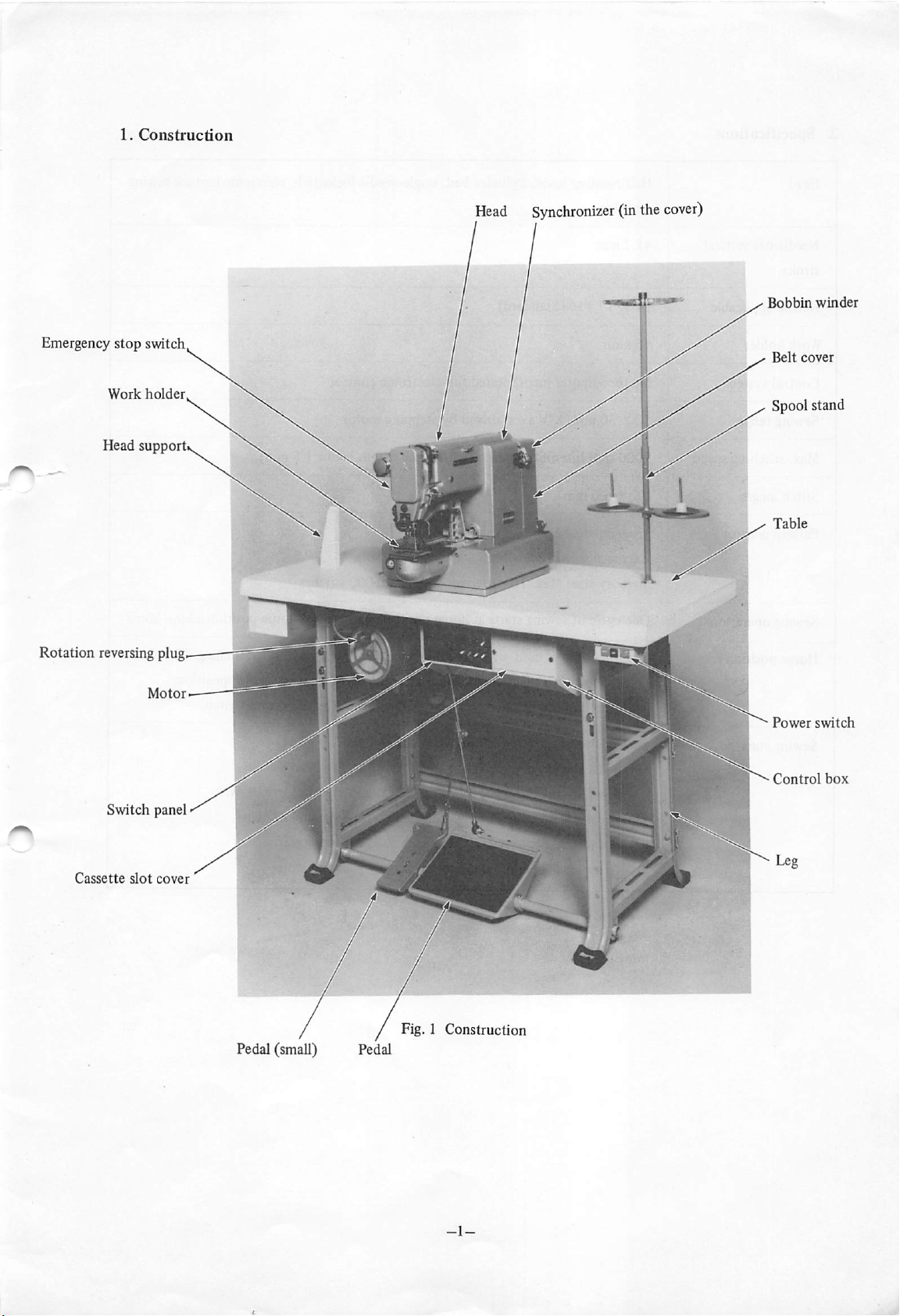
Construction
2. Specifications 2
1
3. Assembling
3.1 Assembling the machine
3.2
3.3 Lamp leads 7
3.4 Electrical power connection 7
3.5 Changing
4. Handling
and
Installation 4
head
Connectionoflead
of
of
Machine Head 8
wires 5
motor
running direction 7
4.1 Installation of needle g
4.2 Threadingofneedle thread 8
4.3 Threadingof bobbin thread 9
4.4
Removal
of inner hook 9
4.5 Adjustment of work holder pressure 10
4
4.6 Replacement of work clamp 10
4.7 Installation of presser-foot ' 11
4.8 Installation of pedal-presser-foot 11
4.9 Winding up of bobbin thread 12
4.10 Thread tension 12
4.11 Lubrication 14
5. Switch Panel 15
5.1 SCALE 15
5.2 SPEED 16
5.3 PATTERN 16
5.4
JOG
5.5 RESET/HOME 17
5.6 TEST/AUTO 17
16
Page 3
5.7
5.8
WIND
ERROR
indication
18
18
6. Operation 19
6.1 Setting the PROM cassette 19
6.2 Setting the switches on switch panel 19
6.3 Checking 19
6.4
Sewing 19
6.5 Emergencystop 20
6.6 Operation procedure 21
7. Cautions on Operation 24
8. Maintenance
and
Checking 25
8.1 Ajustment of synchronizer 25
8.2 Replacementof
PROM
8.3 Cleaningoffan filter 27
26
Page 4
Page 5
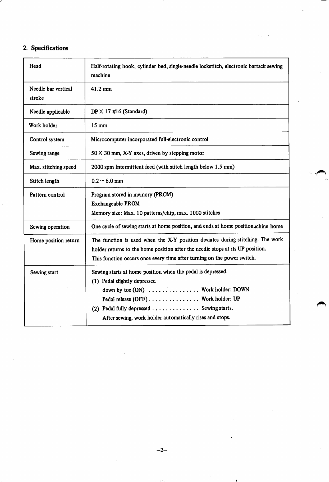
2. Specifications
Head
Needle
bar
vertical
stroke
Needle applicable
Work
holder
Control system
Sewing range 50 X30mm, X-Y axes, drivenbystepping
Half-rotating hook, cylinder bed, single-needle lockstitch, electronic bartack sewing
machine
41.2
mm
DPX 17 #16 (Standard)
15
mm
Microcomputer incorporated full-electronic control
motor
Max. stitching speed 2000 spm Intermittent feed(with stitch length below1.5 mm)
Stitch length
Pattem
control
0.2~6.0
Programstored in memory (PROM)
mm
Exchangeable PROM
Memory size: Max. 10 patterns/chip, max. 1000 stitches
Sewing operation
One cycle of sewingstarts at home position, and ends at home position.ichine home
Home
Sewing
position
start
return
The function is used when the
X-Y
position deviates duringstitching. The work
holder returns to the home position after the needle stops at its UP position.
Thisfunction occurs once every time after turning on the power switch.
Sewing
starts at home positionwhen the pedal isdepressed.
(1) Pedal slightly depressed
down by toe (ON) - Workholder:
Pedal
release
(OFF) Workholder: UP
(2) Pedalfully depressed
Sewing
DOWN
starts.
After sewing,work holder automatically risesand stops.
-2-
Page 6
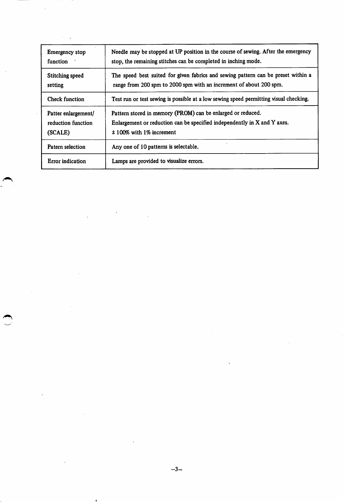
Emergency stop
function
'
Needlemay be stopped at UPposition in the course of
sewing.
stop, the remainingstitches can be completed in inchingmode.
After the emergency
Stitching speed
setting
Check
function
Patter enlargement/
reduction
function
(SCALE)
Patern
selection
Error
indication
The speed best suited for
given
fabrics
and
sewing
pattern can be preset within a
range from 200 spm to 2000 spm with an incrementofabout 200 spm.
Test run or test sewing is possible at a low sewingspeed permitting visualchecking.
Pattern stored in memory (PROM)can be enlargedor reduced.
Enlargementor reduction can be specifiedindependently in X and Y axes.
±
100%
with1%increment
Any oneof10 patterns is selectable.
Lamps are provided to visualize errors.
-3-
Page 7
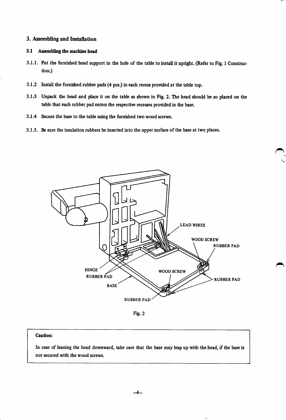
3. Assembling
and
Installation
3.1 Assembling the machine head
3.1.1. Put the furnished head support in the hole of the tableto installit upright.(Referto Fig.1Construc
tion.)
3.1.2 Install the furnished rubber pads(4 pcs.) in each recessprovidedat the table top.
3.L3 Unpack the head and
table
that
each rubber pad enters the respectiverecessesprovided in the base.
place
it on the table as shownin Fig. 2. The head should be so placedon the
3.1.4 Secure the base to the table suing the furnished two woodscrews.
3.1.5. Besure the insulation rubbers be inserted into the upper surface
of
the base at two places.
LEAD
WIRES
WOOD
SCREW
RUBBER
PAD
HINGE
RUBBER
PAD
BASE
RUBBER
PAD
WOOD
SCREW
RUBBER
PAD
Fig. 2
Caution:
In case of leaning the head downward, take care that the base may leap up with the head, if the baseis
not
secured
with
the
wood
screws.
-4-
Page 8
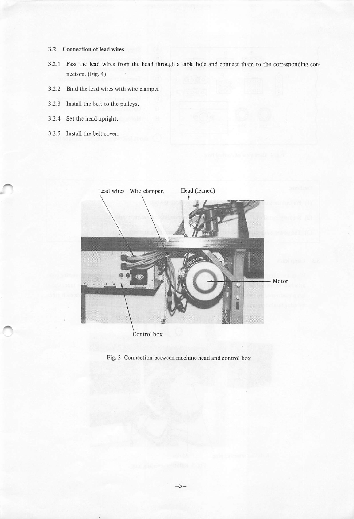
3.2
Connection
of
lead
wires
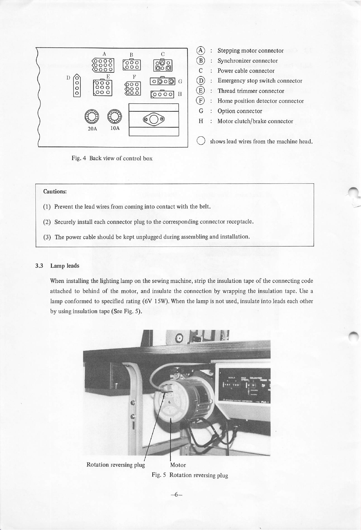
3.2.1 Pass the lead wires from the head through a table hole and connect them to the corresponding con
nectors. (Fig. 4)
3.2.2 Bind the lead wires
with
wire clamper
3.2.3 Install the belt to the pulleys.
3.2.4 Set the head upright.
3.2.5
Install
the
belt
cover.
Lead
wires
Wire
clamper. Head(leaned)
Fig. 3
Control
Connection
box
between machine
head
and
control
box
Page 9
(OOOO
coooo
<poo
20A
o
IDA
O®
O
O^O^l
rocTooi
G
H
(3
Stepping
Synchronizer
Power
Emergency stop switch connector
Thread
Home
Option connector
Motor clutch/brake connector
shows
cable
position
lead
motor
trimmer
wires
connector
connector
connector
connector
detector
from
connector
the
machine
head.
Fig. 4 Back viewofcontrol
Cautions:
(1) Prevent the lead wires from coming
box
into
contact with the belt.
(2) Securelyinstall each connector plug to the correspondingconnector receptacle.
(3) The power cableshould be kept unpluggedduring assembling and installation.
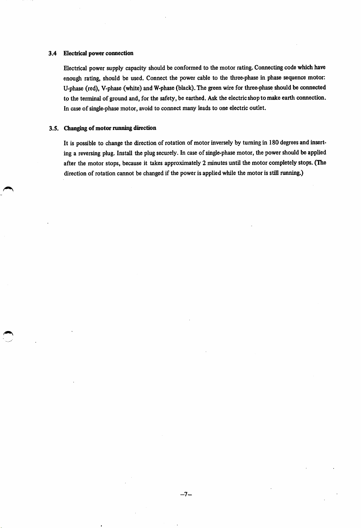
When installing the lighting lamp on the sewing machine, strip the insulation tapeofthe connecting code
attached to behind
lamp conformed to specified rating (6V 15W).When the lamp is not used, insulate into leads each other
by using insulation tape (See Fig. 5).
of
the motor, and insulate the connection by wrapping the insulation tape. Use a
Rotation reversing plug
Motor
Fig.5 Rotation
reversing
plug
Page 10
3.4
Electrical power coimection
Electrical
enough
U-phase
to the terminalof groundand,for the safety,be earthed.Askthe electricshoptomakeearth connection.
In
3.5. Changingofmotorrunning direction
It is
inga
after the motor stops,
directionof rotation cannot be
power
supply
rating,
shouldbeused.
(red),
V-phase
caseofsingle-phase
possibletochange
reversing
plug.
capacity
Connect
(white)
motor,
Install
becauseittakes
the
and
avoid
direction
theplug
changed
shouldbeconformed
the
power
W-phase
to connect manyleadsto one electricoutlet.
(black).
ofrotation ofmotor
securely.Incaseofsingle-phase
approximately2minutes
if the powerisappliedwhilethe motor is stillnmning.)
to themotor
cable
to the
The
green
wire
inverselybyturning
rating.
Connecting
three-phaseinphase
for
three-phase
in 180
motor,thepower
untilthe motor
code
sequence
shouldbeconnected
degrees
shouldbeapplied
completely
which
motor:
and
stops.
have
insert
(TTie
-7-
Page 11

4. HandlingofMachine Head
4.1
Installationofneedle
4.1.1 Beforeinstalling or removingthe needle, be sure to turn
4.1.2
Fully
bar
insert the
hole.
needle
shankinto the
needle
bar hole until it butts
off
the sewingmachine.
against
the bottom of the
4.1.3 Turn front the prime groove of the needleand secure by tighteningthe set screw.
Fully insert needle shank
needle
against bottom
hole,
and tighten set screw.
tum
I !
I I
I I
bar
hole
front
until
it
of
needle bar
prime groove
into
butts
Needle shank is
ed.
not
fully insert
Needle is installedin wrong direc
tion.
A
I I
n ! > n
N=M
d
needle
o
Fig. 6
4.2 Threadingofneedle thread
Thread the needle thread as shown in Fig. 7.
The needle thread passed through the needle eye should extend about 4 cm from the needle eye.
X
-8-
Page 12

4.3 Threading of bobbin du^ad
Pass
case
The
4.4
Removalofinner
Turn
the bobbinthread
into
the
inner
endofthe
the
bobbin
hook clamp in the direction shown by arrow in Fig. 15. Whenthe
throu^
hook.
thread
book
horizontal position, the inner
thehole of the bobbin
should
extend
hook
can be removed.
about
case
horn, asshownin
2.5cmfrom
the
holeofthe
C B
Fig.
13,and set the bobbin
bobbin
hook
case
clamp is
hom.
tumed
to the
4
Fig. 7
-9-
Page 13

4.5 Adjustment of work holder pressure
4.5.1 To increase pressure
work holder shaft by the spanner.
(Length of the work holder shaft and bracket
of
the work holder, loosen the nut shown in Fig. 8 and turn coimter-clockwisethe
"A"
becomeslargewhen the nut is turned counter-clock-
wise.)
4.5.2 By turning the
4.5.3
When
the work holder is adjusted to the standard pressure,it cannot satisfactorilyhold a fabricthicker
than 6 mm. In such a case, decrease the work holder pressure.
nut
clockwise, pressureofthe work holder can be decreased.
4.5.4 With increase of work holder pressure, thickness of fabric that can be held by the work holder de
creases.
4.6 Replacementofwork
To
replace
clamp.
the work clamp,
damp
remove
the work clampset screw
shown
in Fig.8 and
remove
the work
Work clamp set screw
Work clamp
Length
"A
Bracket
Fig. 8
Work
holder
shaft
-10-
Page 14

4.7 Installationofpiesser-foot (Fig. 9)
4.7.1 Install the presser-foot so
that
its lower
end
is in slight contact with the fabric when the fabric is
pressed down.
4.7.2 The presser-foot adjusted too high may causeskip stitch or uneven stitch.
4.7.3 The presser-foot adjusted too low may cause slippage
of
the fabric.
4.7.4 To adjust the presser-foot in height and direction, remove the rubber plug from the face plate and
loosen the presser bar
4.7.5 In
caseofchanging
set
screw shown in Fig. 9.
the thickness of the fabric, confirmthat the presser-foot doesnot touch the work
damp.
Presser
bar
set
screw
Face plate
Presser
bar
Presser-foot-
Fig. 9
4.8 Installation of pedal-presser-foot (Fig. 10)
To install the pedal-presser-foot,remove the motor cover,
and install the chain and the pedal as shown in Fig. 10.
In this
into
case,
contact
take
caretoprevent
with
the
lead
wires.
the
chain
from
Motor
cover
Chain
coming
Pedal
-11-
Fig.
10
Page 15

4.9 Windingupofbobbin thread
4.9.1 Lead the thread from the spool stand, as
shown in Fig. 11,
end
several
turns
and
twine the thread
around
the
bobbin.
4.9.2 Set upward the WIND switch on the
switch panel and then depressthe pedal.
(Refer to 5.7.)
4.9.3 After winding
switch
downward.
4.9.4.Ifthe thread is
up,
set the winding up
not
wound
cylindrically,
Bobbin
move the thread guide toward the
smaller
diameter.
Adjusting
4.9.5 Polyesterthread and nylon thread should bewound at faint tension.
4.10 Thread tension (Fig. 12)
Thread guide
nut
Fig. 11
Balance
Balanced
the
needle
tension
thread
tension
with
the
Unbalanced
Needle
or
bobbin
bobbin
thread
X
tension
thread
thread
Fig. 12
-12-
tight
tension.
loose.
X
Unbalanced
Needle
or bobbin thread tight.
tension
thread
loose
Page 16

4.10.1 Bobbin thread tension (Fig. 13)
The standard bobbin thread tension for
when thread end is held by fingers and the bobbin caseis released.
To adjust bobbin thread tension,turn the thread tensionadjusting screwshownin Fig. 13.
4.10.2 Needle thread tension (Fig. 14)
The needle thread tension should be adjusted with reference to the bobbin thread tension.
To adjust needlethread tension, turn the needlethread tensionadjustingnut shown in Fig. 14.
Bobbin
adjusting screw
flight
Loose
thread
cotton
tension
thread
#60isthat
the
bobbin case gradually goes down
Needle
adjusting
Loose
thread
Tight
tension
nut
Fig. 13
Fig. 14
-13-
Page 17

4.11
Oilgauge
Lubrication
Lubrication port
Hook clamp
OiltopositionsA,B,CandDshowninFig.7before
each oiling position.
For
oilingtotheodinletatthe
Note that too much oil might cause overflow if the head is leaned.
bed
top
(Fig.
15),
Fig. 15
fill
starting
the
oil
gaugeupto
sewing
work.
the
Use
red
marking
several
dropsofoil
with
oil.
for
rN
-14-
Page 18

5.
Switch
Panel
SCALE
SPEED1PATTERN
ERRl
O O
X Y I I
JOG
0
9
_200
RPM
0 "
2000
RPM
RESET
HOME
5.1 SCALE(Pattern Enlargemenl/Reduction)
Thepatterns
programmed
andstoredin the
of 0 to 1.99timesindependently in
ERR2
WIND
TEST
X-axis
SEW
TEST
AUTO
Fig. 16 Switch panel
memory
and
(PROM)
Y-axis
Cover
canbe
enlarged
or reducedwithina
direction. (Stitch lengthis
PROM
enlarged
cassette
range
or reduced.)
Ex.:
Hi
Use
the
switch
within010to
150%(1.5 times)
Fig. 17 Enlargement/Reduction switch
Cautions:
(1)
When
a pattern is enlarged, test should be made to make sure the
able rangerestricted by the work holder frame. (Refer 5.6.1)
(2) Whena pattern is enlarged,stitching speed may decrease. (Refer 7.4)
199%
enlarged
range.
pattern iswithin a
sew-
-15-
Page 19

5.2 SPEED(Stttchmg Speed Control)
The maximum stitching speed can be preset by this switch.
5.3 PATTERN (Pattern Selection)
The desired pattern can be selected by this switch.
5.4
JOG
The work holder can be exactly positioned by operating this switch after depressing the EMERGENCY
STOPswitch (provided on the machine head
5.4.1
When
the
JOG
switch
is set at ®
directionatan inching speed.
....
position,
Fig. 1) to stop the machine.
only
work
holder
advances
in the pattern
1
® 0 i
„
1 ^
—J
Thread
breakage
position
forwarding
5.4.2
5.4.3
When
the
tion at an
When
the
JOG
switch
indiing
JOG
speed.
switchiskept
Fig. 19 JOG switch
Stop
position
Fig. 18 Workholder movingdirection injog operation
isset at 0
©
NEUTRAL
position,
at0 or0
only
position,
work
work
holder
holder
moves
inthe
goesonforwardorbackward.
©
pattern
backwarding
direc
-16-
Page 20

5.5 RESET/HOME
5.5.1 RESET When the switch is set upward, the brake works causingimmediate
stopofthe sewing machine and the machine status is reset.
5.5.2 HOME When the switch is
home
position.
(If
the needle is not at UP position, the needle automatically goesup
set
downward,
the
work holder is
to UP position and the work holder is returned to the home posi
tion.)
In usual operation, the switch is kept downward
5.6 TEST/AUTO
Thisswitchallowsselectionbetweentest sewingand automatic sewing(regularsewing).
5.6.1
TEST
(1) Test run (Only work holder is moved The TEST/AUTO switch to be set downward.)
The work holder moves at a constant speed as far as the pedal is fully depressed by toe, and stops
when the pedal is retumed to NEUTRAL position. When the pedal is depressed by toe again, the
work holder resumes moving to complete remaining pattern motion.
The work holder does not rise when the pedal is returned to NEUTRAL position during the test
run, but rise when the pedal is retumed to NEUTRAL position after the completion of the test
run.
retumedtothe
(HOME
position)
(2) Sewing test (Work holder moves and sewing machine works The TEST/AUTO switch to be
set upward.)
The sewingmachine actually stitches the given fabric at the minimum speed as far as the pedal is
fully depressed, and stops with the needle at UP position after trimming the thread when the pedal
is returnedtoNEUTRAL position.
Whenthe pedal is fully depressedagain, the remaining pattern is sewn up.
The
work
holder
motionissameasthatintest
mn.
NEUTRAL
Slightly depressed
Fully depressed
Fig. 20 Pedal operation
-17-
Page 21

5.6.2
5.7
AUTO
(Actual
With
the
TEST/AUTO
one
cyde
(pattern)iscompleted
ing.
The
work
WIND
When
the
WIND
down
andthe
orYdirection.
When
the
pedalisreturnedtoNEUTRAL
tion.
sewing)
switchasAUTO
holder
goesupautomatically
switchis set upward and the pedal is fully
sewing
machine
starts
position,
even
when
the
afterthe
runningatmedium
position,
sewing
pedalisreturnedtoNEUTRAL
thread
the
startedbydepressing
trimming
speed,
sewing
machine
andthe
depressed
butthe
work
stops
the
pedal
continues
position
wiping
by toe, the work holder
holder
with
after
motions
does
not
the
needleatUP
the
are
move
until
start
over.
goes
inX
posi
Note:
Setting
machine
shouldbedepressed
5.8
ERROR
The
process does not advance.
5.8.1
5.8.2
indication
lamp
lightsinthe
ERR
1
"Green" The lamp
"Red" The lamp
ERR
2
"Green" The lamp
the
WIND
switchtoupward
operationatall.Tostart the
again
afterit is
following
cases
and
entered.
^ Usea conectly programmed
length becomeslarger than 6.0 mm.
50X30
position
winding
once
the
sewing
lights
lights
lights
mm.
while
motion
returnedto
machine
when
when pattern is
when
the
sewing
after
NEUTRAL
stops
with
no input data
PROM
the work
machineisrunning
sewing
operation
position.
the
needleatUP
exists
cassette.
excessively
holder
moves
or incorrect data is
enlarged
over
does
not
ends,
position,
and stitch
the
the
range
affect
pedal
thus
of
Reduce the pattern enlargement factor.
"Red" The lamp lights when temperature in the control box becomes too
high.
Consult
with
-18-
our
service
agency.
Page 22

6.
Operation
6.1 Setting the PROMcassette
Remove the coverofthe switch panel and insert the cassette into the slot.
The
cassette
After the setting, be sure to install the coveragain.
Aspecial
For handlingofthe cassette, refer to 8.2.
6.2
Setting the switches on switch panel
shouldbesetinthe
PROM
writer (PT-100,option) is necessary to eraseand rewrite programin the
correct
direction.
PROM.
In order to check the function, set the switches on the switch panel as shown in Fig. 16.(The
switch should be setto"100"
switch may be set to a suitable numeral within a range from
stored in the PROMapplied.)
6.3 Checking
When
the
above-mentioned
checkasfollows:
(1)
Home
position
(2)
Work
holder
(3)
Work
holder
the
pedalisfully
turnedto
In the
above
the
SEW
switch should be set upward.
Perform
retum:
DOWN:
motion:
depressed
NEUTRAL
checking,
TESTswitchis set
this
switching
for
both
X and Y axes, and the SPEED switch to
"0"
to '*9", depending on the program
preparatory operation has been completed, turn on the powersource and
When
the
power
switch
home
position.
When
the
pedalisslightly
down
(andgoup
The
work
holder
by toe, andstop
positon,
only
the
motion
the
work
downward
operationtocheck
isset to
when
the
should
moveinaccordance
when
stops
withthe
holder
moves
as shownin Fig. 16. To let work the
the
work
ON,
the
work
holder
depressed
by toe, the
work
pedalisreturnedtoNEUTRAL
with
the
the
patternissewn
work
andthe
holder
forits
holder
sewing
positions,
up.
lowered.)
machine
(When
remains
dimensions
"4".
The PATTERN
should
holder
position).
sewing
the
stopped
sewing
SCALE
return
should
pattern
pedal
machine,
and
location.
to the
go
when
is re
when
the
6.4
Sewing
(1) Setthe
(2) Set other
(3)
Setupa
starts
running,itwillgoon
pedalisreturnedtoNEUTRAL
TEST/AUTO
switches
fabric
and
mnning
when
switch
onthe
switch
asinstructedinsection 5.
slightly
depress
the
pedalisfully
until
the
the
sewing
position
pedal,
depressedbytoe.
cycleiscompleted
during
-19-
paneltoAUTO
the
work
the
sewing.
position.
holder
When
and
willgodown.
the
threadistrimmed
sewing
The
sewing
machine
even
machine
once
when
starts
the
Page 23

6.5 Emergency stop
The
sewing
machine
holder remains at
To start again, adjust the restarting position by the JOG switch and depress the pedal. The machine
resumesthe remaining pattem. (Refer to 5.4)
can be
DOWN
immediately
position when the sewingmaching is stopped.
stoppedbydepressing
the
emergency
stop
switch.
Thework
-20-
Page 24

6.6 Operationprocedure
Proceedinaccordance
Checking
before
starting
operation
(1) Is the power cable securely connected?
(2) Are other wiring or cables securely con
nected?
(3) Is the
(4) Are fuses (2 fuses)not blown out?
with
the
following
PROM
cassetteproperly set?
Preparation
start
Pedal
NEUTRAL
Power
switch
Does
Main
motor
run?
flowcharttooperate
ON
^
Power cable wiring
check
Power
switch
OFF
the
sewing
machine.
Section or paragraph
tobereferred
Operation
\
Preparatory
to
operation
Does No
work
holder
to home posi
tion?
WIND
switch
Slightly depress
pedal.
return
ON
HOME
switch to ON,
switchtoON-
and
Set
RESET
Adjustment of
work
holder
Does
work
holder
go
down?
Fully
depress
pedal
Power
switch
o
c
o
0
•o
u
5
Reverse
lationofrota
tion
plug.
ON
instal
reversing
sewing
Does
machine
run?
Pedal
NEUTRAL
Power
switch
OFF
mechanism
4.5
Checking
3.2,
of
3.4
1
o
X
u
-21-
Page 25

Power
Pedal
sw
NI
itch
OFF
lUTRAL
direction
rotation
rect?
Adjustment
synchronizer
Power
switch
OFF
Is
of
cor
Yes.
of
(
Testing
Adjustment
synchronizer
Check
RESET
HOME
PROM
swtich
switch
cassette
ON
ON
No.
>
Pedal
NEUTRAL
Does
needle
stop at
position?
WIND
<
^
(
(^TEST
switch
Pattern
selection
SCALE
swtich
Fully
pedal.
Does
work
move?
UP^
Yes.
OFF
^
setting
^
ON
\
depress
"
holder
>
Power
OFF
switch
Check
the
mechanism
cotnrol
box
driving
and
the
Pedal
NEUTRAL
relation^ip
between
work
Preparation
completed
Is
pattern
holder
conect?
holder
and
-22-
Adjustment
the
work
of
holder
Page 26

CJD
^
Sewing
^
Speed
AUTO
<
Fabric
up
<
start
setting
switch
ON
setting
^
^
)
Automatic
opeiation
(Actual
sewing)
Slightly depress
pedal
Is
fabric
secure
ly held?
Fully
depress
pedal
Does ^ No.
sewing machine
run
Pedal
NEUTRAL
Is Yes.
thread
broken
in
the
course
sewing?
Yes.
Pedal
NEUTRAL
PROM
data
error
Power
switch
OFF
Emergency
switch
of
fabric
properly?
ON
Is \
located
stop
No
Adjustbyop
erating
JOG
switch
thread
at
work
thread
work
the
ewing?
Does
wiper
torily?
Does
torily?^
stitching
even
Is \ No
trimmed
end
of
Ves
satisfac
Yes.
\
trimmer
satisfac
Is ^ No
No
Yes.
-23-
Fully depress
pedal
Power
switch
OFF
Adjustment
sewing
machine
of
Page 27

7.
CautionsonOperation
7.1 Before replacing
also noted that the power switch is set to OFF before insertion and removalofthe PROMcassette.
7.2
If
any ERR lamp lights, check for cause, referring to 5.8, and remedy.
PROM
in the
PROM
cassette, be sure to carefullyread 8.2 in this manual.Itshould be
7.3 When a new pattern is sewn, or pattern is enlarged, do not fail to check the relationshipbetween the
work holder and the pattern by conducting test operation.
7.4 The maximum stitching speed depends on stitch length, and is automatically restricted in connection
with stitch length as listed in Table 1.
Table
Stitch length
Below6mm
Below5mm
Below4mm
Below3mm
Below2mm
Below
1.5
mm
Max. speed
600
spm
850
spm
1100 spm
1400
spm
1600 spm
2000 spm
1
Sewing machine max. speed in con
nection with stitch length.
7.5 The
7.6 The foot
cover
of the control
malfunctionordefectofthe
device
shouldbereleased
phase
motor,
avoid
to operate the
shouldbe
machine.
from
the
pedal
closed,
pedal
before
because
during
settingthe
combination of the motor
"ON" (approx. 10 seconds).
7.7 The powershouldbe "OFF", priorto adjustmentof the
device for adjusting.
7.8
Avoid
a check of the interior control circuit
energizedby voltageof the tester and
damage
using
of these parts may be caused.
entranceof dustinto control
power
"ON" or "OFF". In
warming-up
sewing
machineoropening
a tester,
because
the parts of semiconductor are
device
caseofsingle-
afterthe
the
cover
maycause
power
of control
-24-
Page 28

8. Maintenance and Checking
8.1 Adjustment of synchronizer
Belt
cover
8.1.1
Remove
the
belt
cover.
To remove the belt cover, loosen the set screw, pull
up the belt cover and draw in the directionofanow
shown in Fig. 21.
Set
screw
Fig. 21
s
8.1.2 Adjustment
Ring
magnet
Machine
Gap
0.5-1.0
of
synchronizer gaps.
Adjust the gaps as illustrated in Fig. 22.
Directionofrotation
shaft
mm
\ /
V ' ^
. 1
\ ^
-"
Magnet
Magnet "B'
"A'
Gap
0.3—1.0
mm
8.1.3 Adjustmentofstop position
Arm
lO
\
Reference
Take-up lever
Fig. 23
Bracket
Fig.22 Synchronizer gapadjustment
Adjust the machine stop position so
lever
mark
thread
arm during
-25-
hole
the
the
DOWN
reference
;ip
meets
upward strokeofthe
that
the take-up
mark
on
take-up lever.
the
Page 29

8.2 ReplacementofPROM
Cover
PROM is installed on the
To
replace
(1)
(2) Take
(3)
(4)
PROM,
Lever
up the cassette casecover
out
the PC board from the cassette case.
Carefully
remove
Insertanew
shown in figure. PROM might be damaged,ifinstalled in wrong direction.
socketofPC
proceedasfollows
the
PROM
PROM
into the IC
from
board
in the cassette.
(see
Fig.
24 and 25):
usingascrewdriver.
theICsocket
socket
usingascrewdriver
in such way that the
PROMisinstalled
(5) Install the PC board in the cassette case and cover the cassette case.
D]
,
Printed
circuit
board
Lamp
PROM
oranyother
PROM
o
IC
socket
suitable
in the direction as
IC
pin
1
NotchofIC
means.
No.
I
Printed
board
circuit
socket
P]
Fig. 24 Cassette case
Notch
board
of
the
pin side.
IC
should
Fig. 25 PC board
come
to
the
PC
-26-
Page 30

8.3
Deaningoffan
8.3.1
Remove
the
external
filter
filter.
To remove, lever the external filter using a screwdriver.
8.3.2
8.3.3
Remove
Put
the
dust
from
extemal
the
filter
external
into
the
filter
keyway
and
to install it again.
Keyway Internal filter Extemal filter
internal
filter.
Fig. 26 Filter
Page 31

(8309)
A
ROD
MITSUBISHI
HEAD OFFtC&MITSUBtSHI DENKI BLDG.MARUNOUCKI TOKYO
ELECTRIC
CORPORATION
100
TELEX:
J24S32
CABLE MELCO TOKYO
 Loading...