

Page 1
MITSUBISHI
Industrial
Sewing
INSTRUCTION
Single-Needle
Electronic
Model
Bar
Machine
MANUAL
PLK-0604
Lockstitch
Tack
Machine
A
MITSUBISHI
ELECTRIC
Page 2
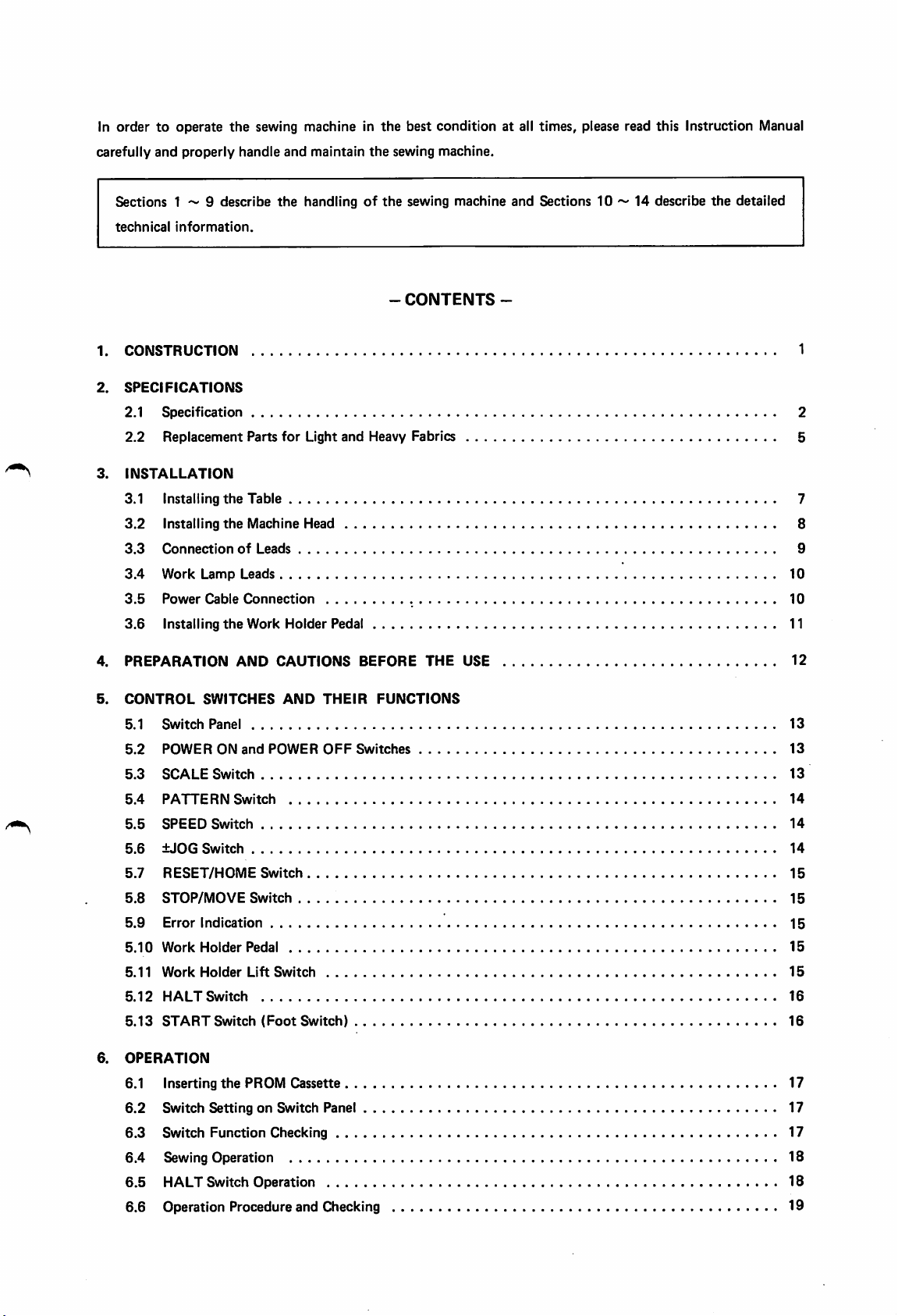
In
ordertooperate
carefully
and
properly
the
sewing machine in
handle
and
maintain
the
the
sewing
best
condition
machine.
at all times, please read this Instruction Manual
Sections 1 9 describe
technical
1.
CONSTRUCTION
2.
SPECIFICATIONS
2.1
2.2
3.
INSTALLATION
information.
Specification
Replacement
3.1 Installing
3.2
Installing
3.3
Connection
3.4
Work
Lamp
3.5
Power
Cable
3.6
Installing
Parts
the
Table
the
Machine
of
Leads
Connection
the
Work
Leads
the
handlingofthe
for
Light
and
sewing
-
CONTENTS
machine
-
and
Sections
10
14 describe
the
detailed
Heavy Fabrics 5
Head 8
Holder
Pedal 11
1
2
7
9
10
10
4.
PREPARATION
5.
CONTROL
5.1
5.2
5.3
5.4
5.5
5.6
5.7
5.8
5.9
5.10
5.11
5.12
5.13
6.
OPERATION
6.1 Inserting
6.2
6.3
Switch
POWER
SCALE
PATTERN
SPEED
±JOG
RESET/HOME
STOP/MOVE
Error
Work
Work
HALT
START
Switch
Switch
AND
CAUTIONS
SWITCHES
Panel
ON
Switch
Switch
Switch
Switch
Indication
Holder
Holder
Switch
Switch
the
Setting
Function
AND
and
POWER
Switch
Switch
Pedal
Lift
Switch
(Foot
Switch)
PROM Cassette 17
on Switch Panel 17
Checking 17
THEIR
OFF
BEFORE
FUNCTIONS
Switches
THE
USE
6.4 Sewing Operation 18
6.5
HALT Switch Operation 18
6.6 Operation Procedure and Checking 19
12
13
13
13
14
14
14
15
15
15
15
15
16
16
Page 3
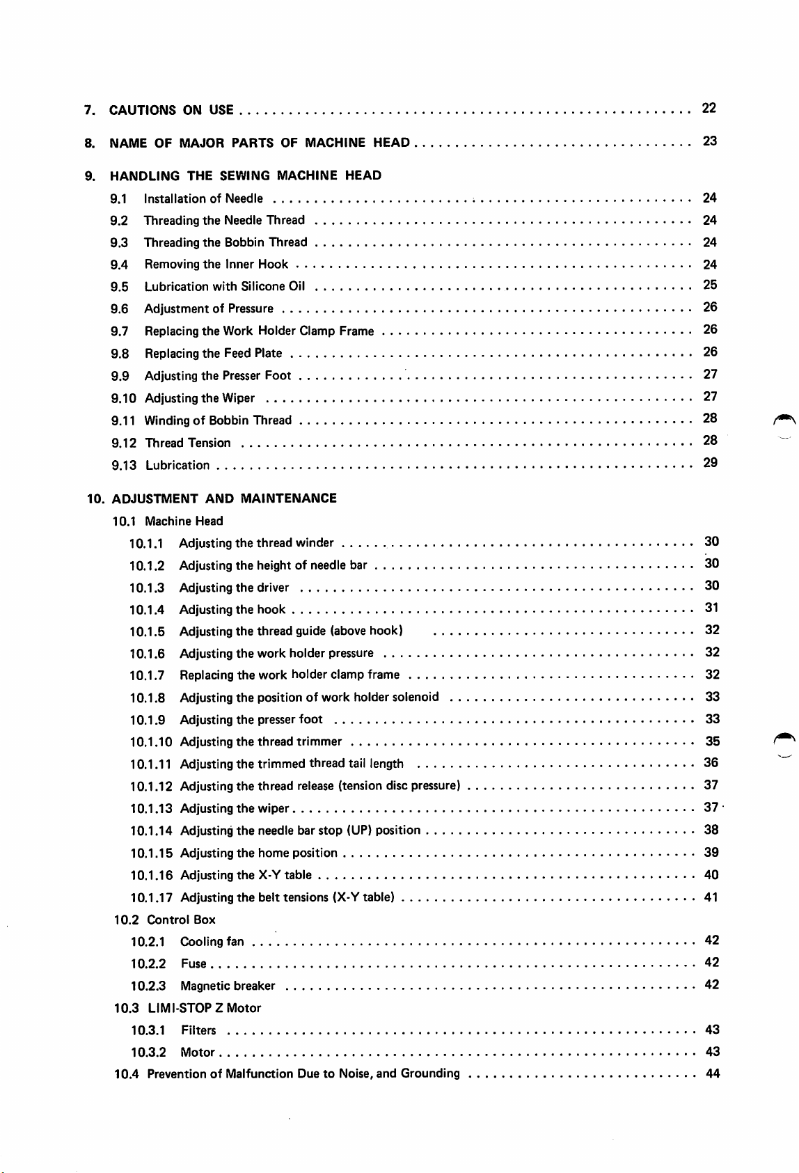
7. CAUTIONS ON USE 22
8. NAME
9.
HANDLING
9.1
9.2
9.3
9.4
9.5
OF
MAJOR
THE
InstallationofNeedle
Threading
Threading
Removing
Lubrication
the
the
the
with
PARTS
SEWING
Needle
Bobbin
Inner
Silicone
OF MACHINE HEAD 23
MACHINE
HEAD
Thread
Thread
Hook
Oil
9.6 Adjustment of Pressure 26
9.7 Replacingthe Work Holder Clamp Frame 26
9.8 Replacing the Feed Plate 26
9.9 Adjusting the Presser Foot 27
9.10 Adjusting the Wiper 27
9.11
WindingofBobbin
Thread 28
9.12 Thread Tension 28
9.13 Lubrication 29
10.
ADJUSTMENT
10.1
Machine
AND
Head
MAINTENANCE
10.1.1 Adjusting the thread winder 30
10.1.2 Adjusting the height of
needle
bar 30
10.1.3 Adjusting the driver 30
10.1.4 Adjustingthe hook 31
10.1.5 Adjusting the thread guide (above hook) 32
10.1.6 Adjusting the work holder pressure 32
10.1.7 Replacing
10.1.8 Adjusting
10.1.9
10.1.10
Adjusting
Adjusting
the
work holder clamp frame 32
the
position of work holder solenoid 33
the
presser
foot
the
thread
trimmer
10.1.11 Adjusting the trimmed thread tail length 36
10.1.12 Adjusting the thread release (tension disc pressure) 37
10.1.13 Adjusting
10.1.14 Adjusting
10.1.15
10.1.16
Adjusting
Adjusting
10.1.17 Adjusting
10.2
Control
Box
the
wiper 37
the
needle bar
the
home
the
X-Y
the
belt tensions (X-Y table) 41
position
table
stop
(UP) position
10.2.1 Cooling fan 42
10.2.2
Fuse
10.2.3 Magneticbreaker 42
10.3
LIMI-STOPZ
10.3.1
10.3.2
10.4
Filters
Motor
PreventionofMalfunction
Motor
DuetoNoise,
and
Grounding
24
24
24
24
25
33
35
38
39
40
42
43
43
44
Page 4
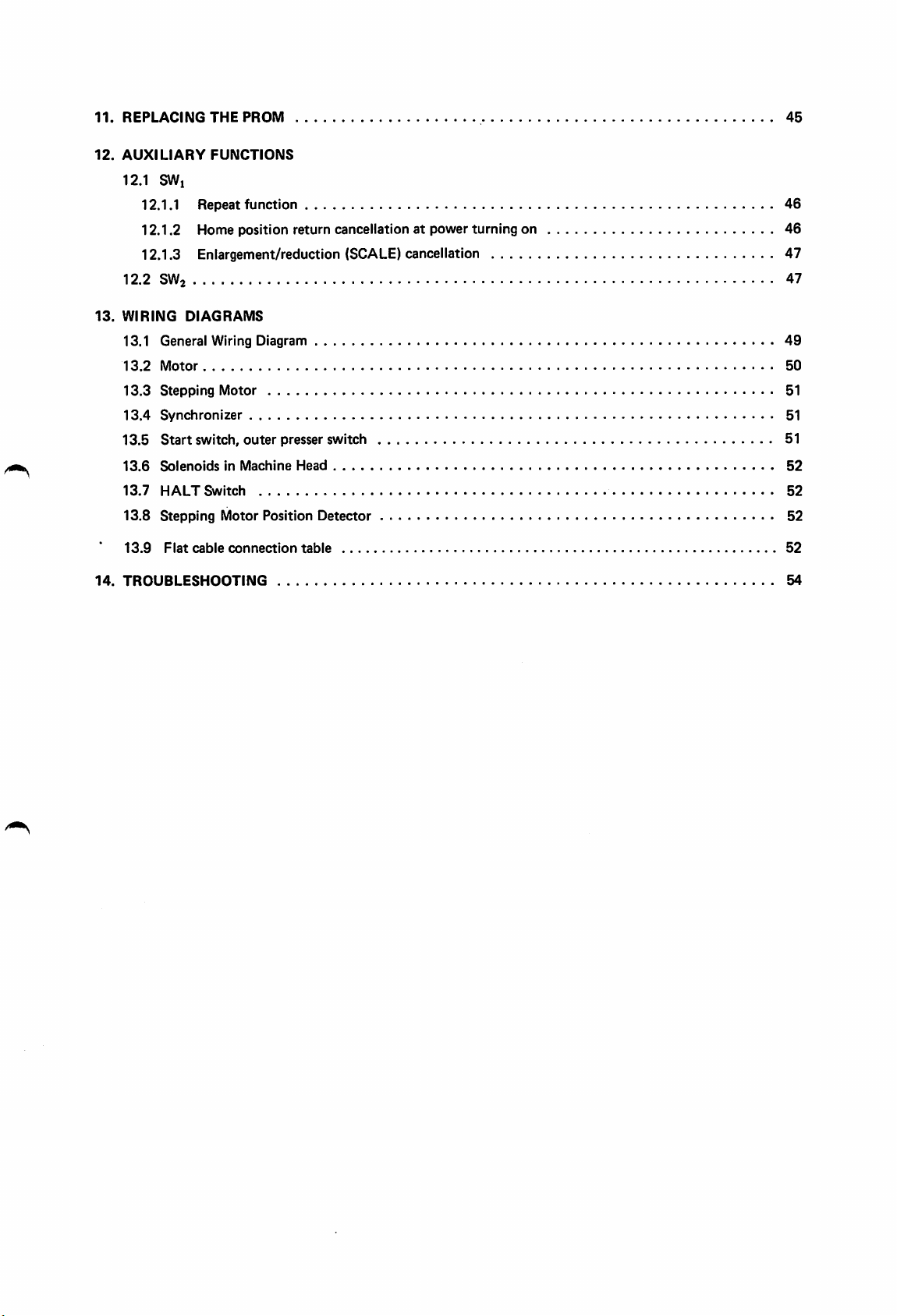
11.
12.
REPLACING
AUXILIARY
THE
PROM
FUNCTIONS
12.1 SWi
12.1.1 Repeat
function
12.1.2 Home position return cancellation at power turning on
12.1.3 Enlargement/reduction (SCALE) cancellation 47
12.2 SW2 47
13.
WIRING
DIAGRAMS
13.1 General Wiring Diagram
13.2
Motor
13.3
Stepping
13.4
Synchronizer
13.5
Start
13.6
SolenoidsinMachine
13.7
HALT
13.8
Stepping
13.9
Flat
Motor
switch,
Switch
cable
outer
Motor
connection
presser switch 51
Head
Position
Detector
table
45
46
46
49
50
51
51
52
52
52
52
14.
TROUBLESHOOTING
54
Page 5

Page 6
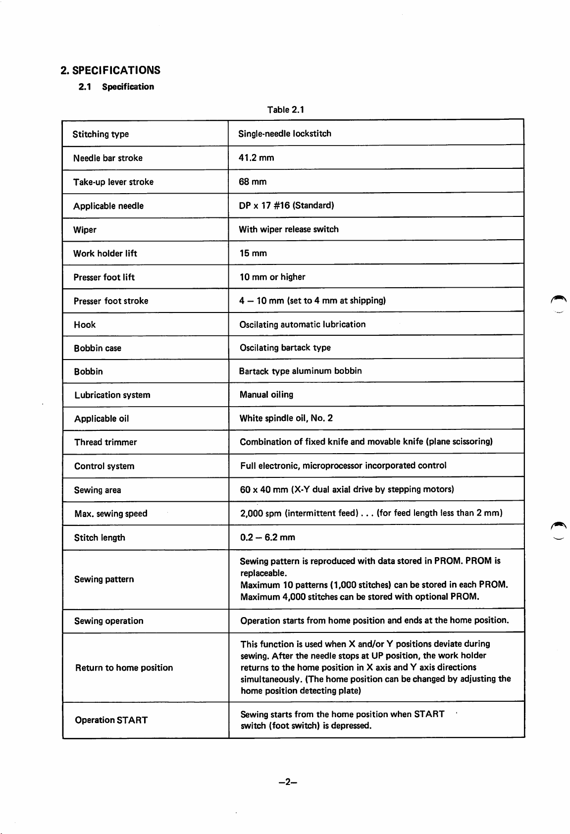
2.
SPECIFICATIONS
2.1
Specification
Table
2.1
Stitching
Needle
bar
Take-up
Applicable
Wiper
Work
holder
Presser
foot
Presser
foot
Hook
Bobbin
Bobbin
Applicable
case
Lubrication
type
stroke
lever
needle
oil
stroke
lift
lift
stroke
system
Single-needle lockstitch
41.2
mm
68
mm
DP X 17
With
15
10
4 —10mm
Oscilating
Oscilating
Bartack
Manual
White
#16
(Standard)
wiper
release
mm
mmorhigher
(setto4
automatic
bartack
type
aluminum
oiling
spindle
oil.
switch
mmatshipping)
lubrication
type
No.
bobbin
2
Thread
Control
Sewing
Stitch
Sewing
Sewing
trimmer
system
area
Max. sewing
Returntohome
Operation
speed
length
pattern
operation
START
position
Combinationoffixed
Full
electronic,
60X40
2,000
spm (intermittent
0.2—6.2
Sewing
replaceable.
pattern
mm
(X-Y
mm
microprocessor
dual
is reproduced
Maximum10patterns
Maximum
Operation
This
sewing.
returnstothe
simultaneously.
home
Sewing
switch
4,000
starts
function
After
position
starts
(foot
stitches
from
is used
the
needle
home
(The
detecting
from
the
switch)isdepressed.
knife
and
movable
incorporated
axial drive by
feed)...
with
(1,000
stitches)
canbestored
home
position
knife
control
stepping
(for feed length less
data
stored
canbestored
with
optional PROM.
and
endsatthe
whenXand/orYpositions
stopsatUP position,
position
home
plate)
home
in X axis
position
position
and
Y axis
canbechanged
when
START
(plane
scissoring)
motors)
than
2 mm)
in PROM. PROM is
in each PROM.
home
position.
deviate
the
work
during
holder
directions
by adjusting
the
-2-
Page 7
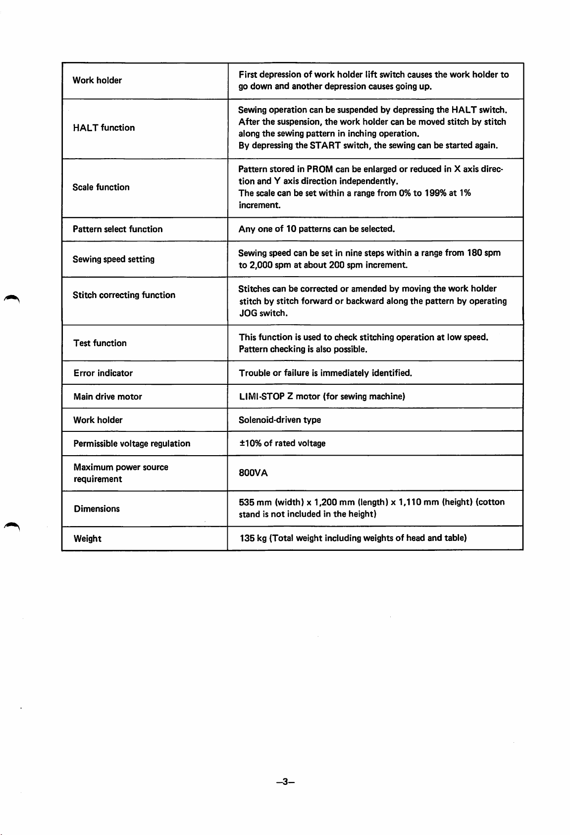
Work
holder
First
depressionofwork
go
down
and
another
holder
lift
switch
causes
depression causes going up.
the
work
holder
to
HALT
Scale
Pattern
Sewing
Stitch
Test
Error
Main
function
function
select
speed
correcting
function
indicator
drive
setting
motor
function
function
Sewing
After
along
By depressing
Pattern
tion
The
increment.
Any
Sewing
to
Stitches
stitchbystitch
JOG
This
Pattern
operation
the
suspension,
the
sewing
storedinPROM
and
Y axis
scale
canbeset
oneof10
speed
2,000
spmatabout
canbesuspendedbydepressing
pattern
the
START
direction
patterns
canbeset
canbecorrectedoramendedbymoving
forwardorbackward
switch.
function
is usedtocheck
checking
is also possible.
Troubleorfailure is
LIMl-STOP Z
motor
the
work
holder
canbemoved
in inching
switch,
canbeenlargedorreduced
operation.
the
sewing
independently.
within
a range
from0%to
canbeselected.
in nine
200
immediately
(for
steps
within
spm
increment.
along
stitching
operationatlow
identified.
sewing machine)
the
HALT
stitchbystitch
canbestarted
in X
axis
199%at1%
a range
the
from
the
work
patternbyoperating
speed.
switch.
again.
180
holder
direc
spm
Work
holder
Permissible
Maximum
requirement
Dimensions
Weight
voltage
power
regulation
source
Solenoid-driven
±10%ofrated
800VA
535
mm (width) x
standisnot
135
kg (Total weight including weights of head
type
voltage
1,200
includedinthe
mm (length) x
height)
1,110
mm (height)
and
table)
(cotton
-3-
Page 8
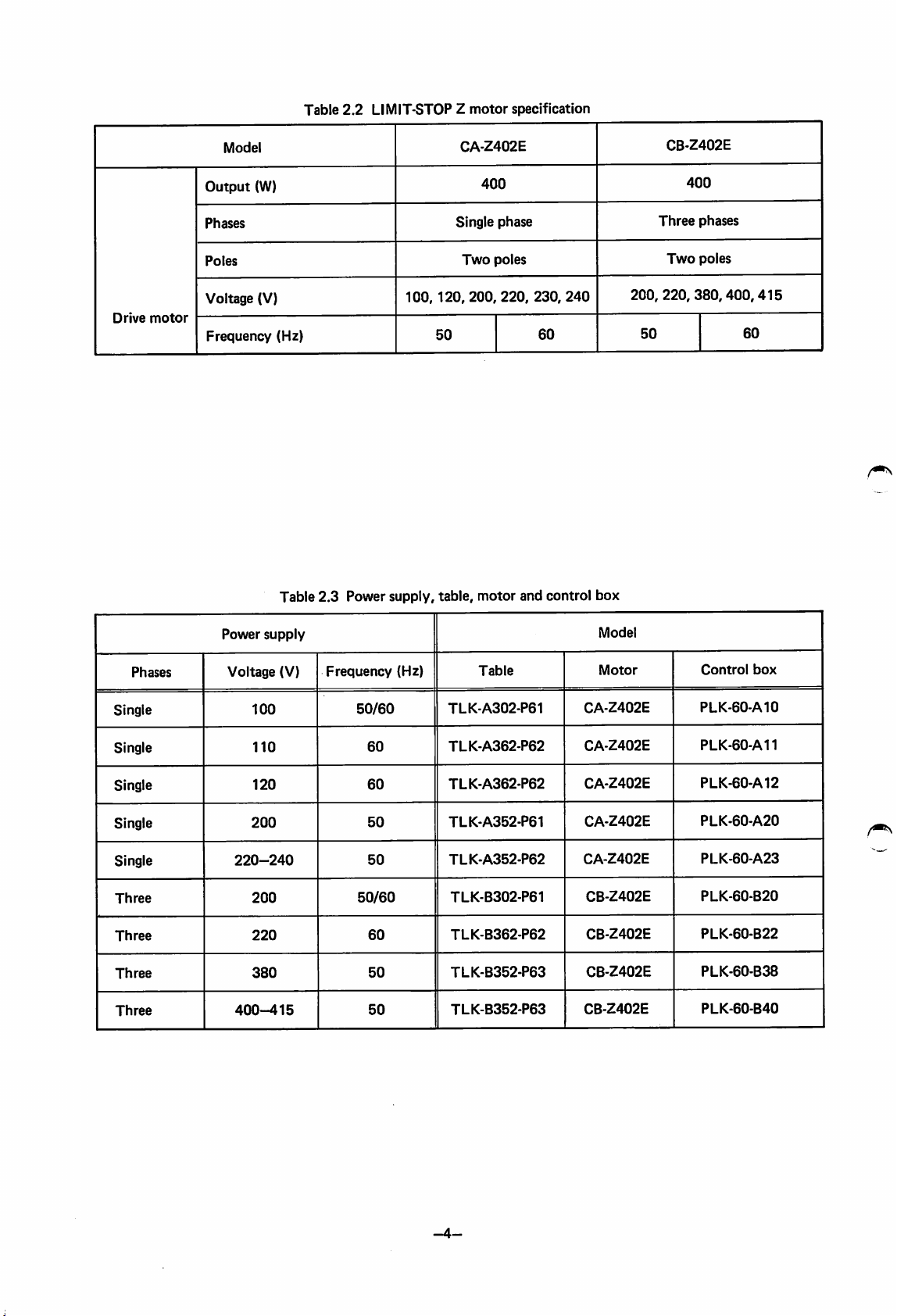
Table
2.2
LIMIT-STOP Z
motor
specification
Drive
motor
Model
Output
Phases
Poles
Voltage
Frequency
(W)
(V)
(Hz)
Table
2.3
Power
100,
supply,
Single
120,
50
table,
CA-Z402E
400
phase
Two
poles
200,
220,
motor
and
230,
60
control
240
box
CB-Z402E
Three
Two
200, 220,
50
400
phases
poles
380,400,415
60
Phases
Single
Single
Single
Single
Single
Three
Three
Three
Three
Power
Voltage
220-240
400-415
supply
100
110
120
200
200
220
380
(V)
Frequency
50/60
60
60
50
50
50/60
60
50
50
(Hz)
Table
TLK-A302-P61
TLK-A362-P62
TLK-A362-P62
TLK-A352-P61
TLK-A352-P62
TLK-B302-P61
TLK-B362-P62
TLK-B352-P63
TLK-B352-P63
Model
Motor
CA-Z402E
CA-Z402E
CA-Z402E
CA-Z402E
CA-Z402E
CB-Z402E
CB-Z402E
CB-Z402E
CB-Z402E
Control
PLK-60-A10
PLK-60-A11
PLK-60-A12
PLK-60-A20
PLK.60-A23
PLK-60-B20
PLK-60-B22
PLK-60-B38
PLK-60-B40
box
Page 9
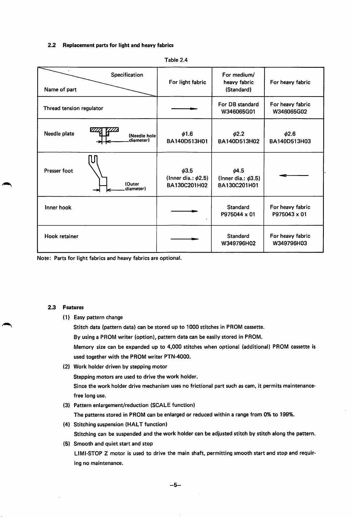
2.2
Replacement
parts
for
light
and
heavy
fabrics
Table
2.4
Nameofpart
Thread
Needle
Presser
Inner
Hook
tension
plate
foot
hook
retainer
regulator
E^-pza
Specification
(Needle
.diameter)
(Outer
^
diameter)
hole
For
light
fabric
01.6
BA140D513H01
03.5
(Inner
dia.;
BA130C201H02
02.5)
For
medium/
heavy
fabric
(Standard)
For
DB
standard
W346065G01
02.2
BA140D513H02
04.5
(Inner dia.:
BA130C201H01
Standard
P975044X01
Standard
W349796H02
03.5)
For
heavy
fabric
For
heavy
fabric
W346065G02
02.6
BA140D513H03
For
heavy
fabric
P975043X01
For
heavy
fabric
W349796H03
Note:
2.3
Parts
for
light
fabrics
and
heavy
fabrics
are
optional.
Features
(1) Easy
(2)
(3)
(4)
pattern
Stitch
By using a PROM
Memory size
together
used
Work
change
data
(pattern
canbeexpandedupto
with
holder
drivenbystepping
data)
writer
the
canbestoredupto
(option),
PROM
writer
Stepping motors are used to drive
Since
the
work
holder
drive
mechanism
free
long
use.
Pattern
The
Stitching
enlargement/reduction
patterns
stored
suspension
in PROM can be enlarged or reduced
(HALT
function)
pattern
PTN-4000.
motor
the
(SCALE
1000
data
can be easily
4,000
stitches
work
holder.
usesnofrictional
function)
stitches
when
in PROM
stored
optional
part
within
cassette.
in PROM.
(additional) PROM
suchascam,itpermits
a range from 0%to199%.
maintenance-
Stitching can be suspended and the work holder can be adjusted stitch by stitch along the pattern.
(5)
Smooth
LIMI-STOP Z
ingnomaintenance.
and
quiet
motor
start
and
stop
is usedtodrive
the
main
shaft,
permitting
smooth
start
and
stop
cassette
and
requir
is
-5-
Page 10
(6) Test function for checking
the
pattern
The work holder movement and stitching motion can be tested at low speed.This function is very
helpful
(7) Various
oPROM
whenanew
safety
functions
cassette
oData
input
o Excessive
oWork
oMotorormachine
oV-belt
trouble.
Error
holder
outofpulleyorbreakage
indication
loading
error
enlargement
overrun
pattern
detection
alarm
standstill
lamps
is stored.
confirmation
alarm
alarm
are
usedtogive
(duetooverload)
alarm
alarms,
permitting
immediate
identification of
(8) Microprocessor incorporated full-electronic control system
8-bit
(9)
microprocessor is used in
Automatic
home
position
return
the
control
function
system.
Since the work holder automatically returnsto the home positionwhen one pattern iscompleted,
error
dose
not
accumulate.
cause
of
-6-
Page 11
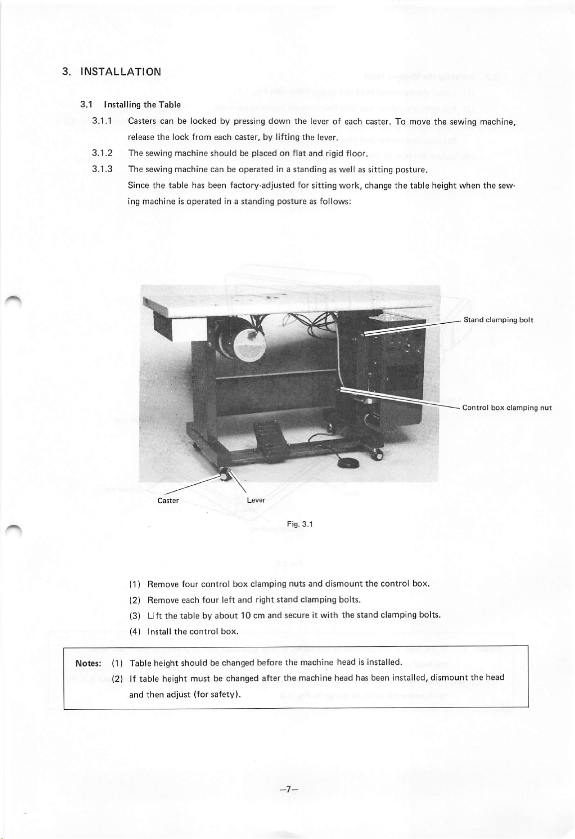
3.
INSTALLATION
3.1
3.1.1 Casters can be locked by pressing down the lever of each caster. To move
3.1.2
3.1.3
Installing
the
release
Table
the
lock
from
each
caster, by lifting
the
The sewing machine should be placed on flat and rigid floor.
The
sewing
machine
Since
the
table has been factory-adjusted for sitting
ing
machineisoperated
canbeoperated
in a
standing
in a
standing
postureasfollows:
lever.
as well as
work,
sitting
change
the
posture.
the
table height when
sewing machine,
the
sew
Stand
clamping
bolt
Fig. 3.1
(1) Remove
(2) Remove each
(3) Lift the table by
(4)
Install
the
four
control
control
four
about
box.
box clamping nuts and
left
and
right
stand
dismount
clamping
bolts.
the
control
10 cm and secure it with the stand clamping bolts.
Notes: (1) Table height should be changed before the machine head is installed.
(2) If table height must be changed after the machine head has been installed, dismount the head
and
then
adjust
(for
safety).
box.
Control
box
clamping
nut
Page 12
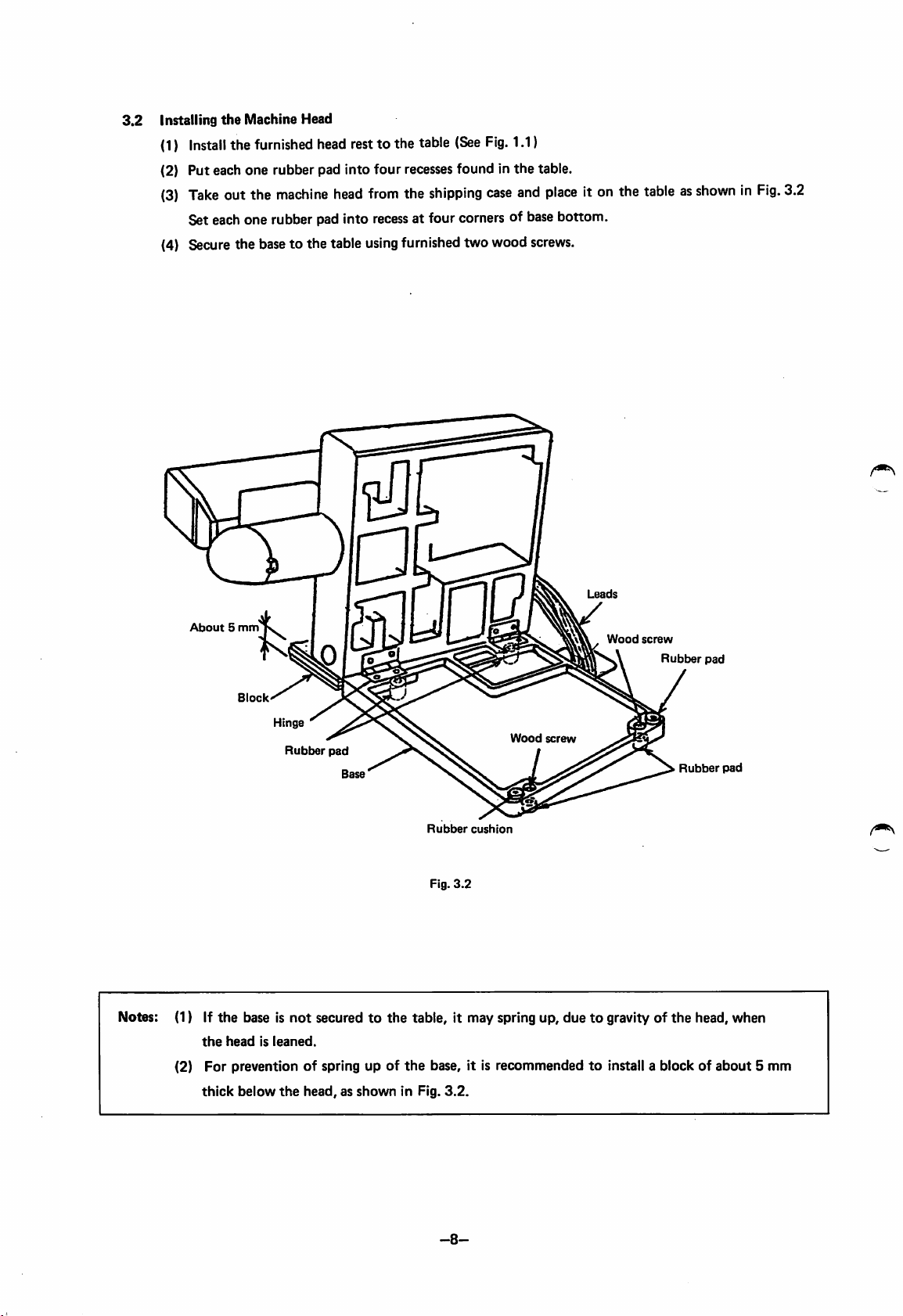
3.2
Installing
(1)
(2) Put each one rubber pad into four recesses found in
(3)
the
Machine Head
Install
the
Take
furnished
outthe
headrestto the table
machine
head
Set each one rubber pad into
from
the
shipping
recess
at four corners of base bottom.
(4) Secure the baseto the table usingfurnished two wood
El
(See
Fig.
case
1.1)
the
and
table.
place
screws.
it on the
tableasshowninFig.
3.2
About5mm
Notes: (1) If
(2)
Block
Hinge
Rubber
the
base is
not
securedtothe
the
headisleaned.
For
prevention of spring up of
thick
below
the
head,asshown
pad
P
Leads
.
Wood
M
wood
screw
Rubber
cushion
Fig.
3.2
table, it may spring up, duetogravity of
the
base, it is recommendedtoinstall a block of
in Fig.
3.2.
screw
Rubber
Rubber
the
pad
pad
head, when
about
5 mm
-8-
Page 13
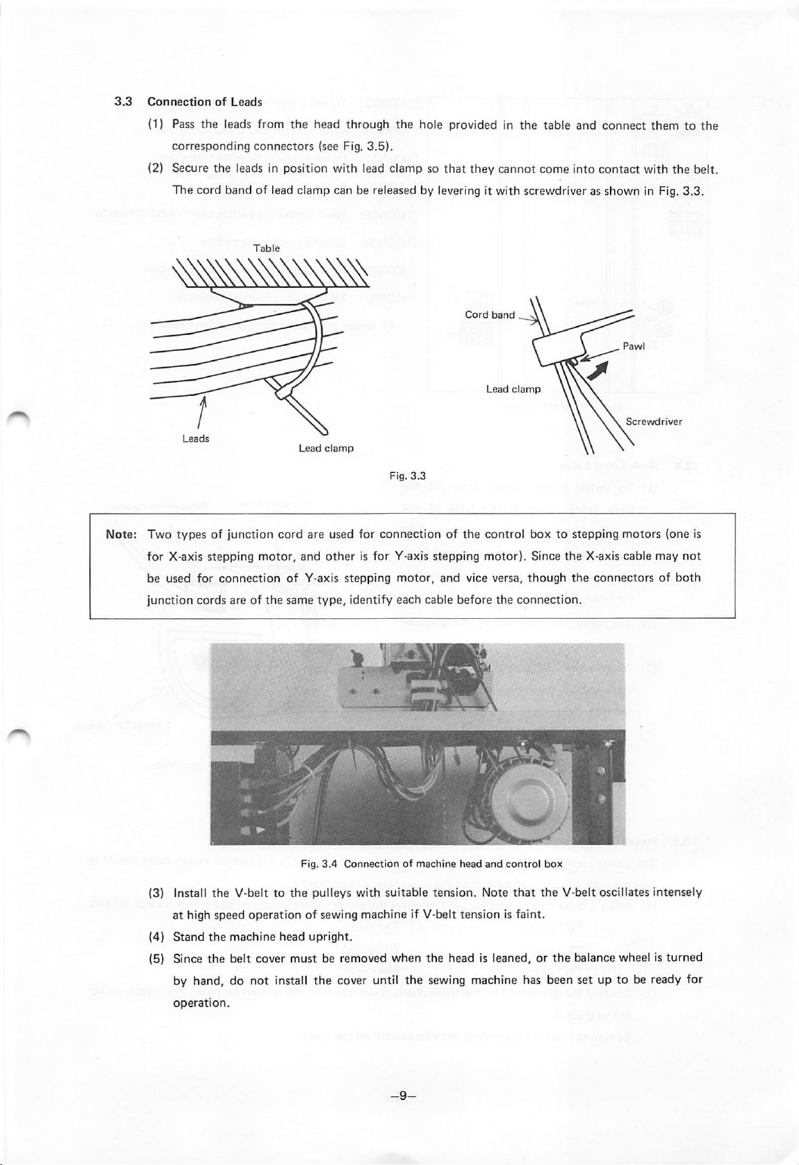
3.3
Connection
of
Leads
(1} Pass the leads from the head through the hole provided in the table and connect them to the
corresponding
(2) Secure the leads in position with lead clamp so
connectors
(see Fig.
3.5).
that
they
cannot come into contact with
The cord band of lead clamp can be released by levering it with screwdriver as shown in Fig.
Cord
band
Lead
clamp
Screwdriver
Lead
clamp
Fig.
3.3
the
belt.
3.3,
Note: Two
for
be
junction
(3) Install
(4)
(5) Since
typesofjunction
X-axis
stepping
used
for
connection
cords are of
the
V-belttothe
at
high
speed
Stand
the
machine
the
belt cover must be removed
cord
are used for
motor,
the
and
of
same
Fig.
otherisfor
Y-axis
stepping
type,
3.4
Connectionofmachine
pulleys
operationofsewing
head
upright.
connectionofthe
Y-axis
stepping
motor,
and
control
motor).
vice versa,
identify each cable before the
head
and
with
suitable
machine
when
tension.
if V-belt
tensionisfaint.
the
head is leaned, or
Note
box to stepping
Since
though
connection.
control
box
that
the
the
motors
the
X-axis
cable
the
connectorsofboth
V-belt oscillates
balance wheel is
(one is
may
intensely
turned
by hand, do not install the cover until the sewing machine has been set up to be ready for
operation.
not
Page 14
ooo
ooo
ooo
ooo
OOP
Iddbdl
00
oooo
O
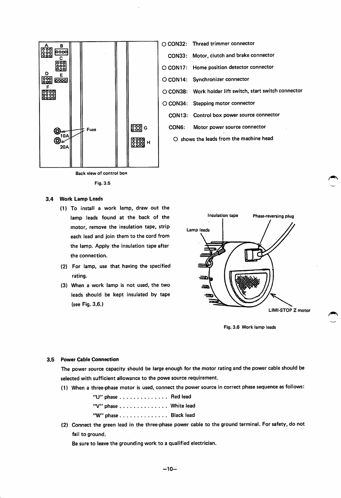
CON32:
CON33;
lOOOl
ooo
ooo
O CON 17:
OCON14:
oo
O CON38: Work holder lift switch, start switch connector
O
CON34:
CON
Thread
Motor,
Home
Synchronizer
Stepping
13:
Control
trimmer
clutch
position
motor
box
connector
and
brake
detector
connector
connector
power
source
connector
connector
connector
3.4
Work
(1) To install a
lamp leads found at
motor,
each
the
the
(2) For lamp, use
(3) When a
Fuse
Back
viewofcontrol
Lamp
lead
lamp. Apply
connection.
rating.
leads
should
(see Fig.
Fig.
Leads
remove
and
work
3.6.)
po^
I
odoo
oooo
box
3.5
work
lamp,
the
the
insulation tape, strip
join
themtothe
the
insulation
that
having
lampisnot
be
kept
insulated
oo
draw
back of
cord
the
used,
out
from
tape
after
specified
the
by
the
the
two
tape
C0N6:
O shows
Lamp
Motor
power
source
connector
the
leads
from
the
machine
Insulation tape Phase-reversing plug
leads
head
LIMI-STOPZmotor
Fig.
3.6
Work
3.5
Power
Cable
Connection
The power source capacity should be
selected
(1)
with
sufficient
When
a three-phase motor is used,connect the powersource in correct phasesequence asfollows:
"U"
"V"
"W"
allowancetothe
phase Red lead
phase
phase Black lead
large
enoughfor the motor ratingand the powercableshould be
powe
source
requirement.
White lead
(2) Connect the green lead in the three-phase power cable to the ground terminal. For safety, do not
failtoground.
Be
suretoleave
the
grounding
worktoa qualified electrician.
-10-
lamp
leads
Page 15
(3)
Whenasingle-phase
wall
outlet.
motor is
used,
do not
plug
the
power
cord to a
branch
socket,but
plug
to a
Notes: (1) All leads should be bundled and secured in position so
with
the
V-belt.
(2) Securely
(3) Before
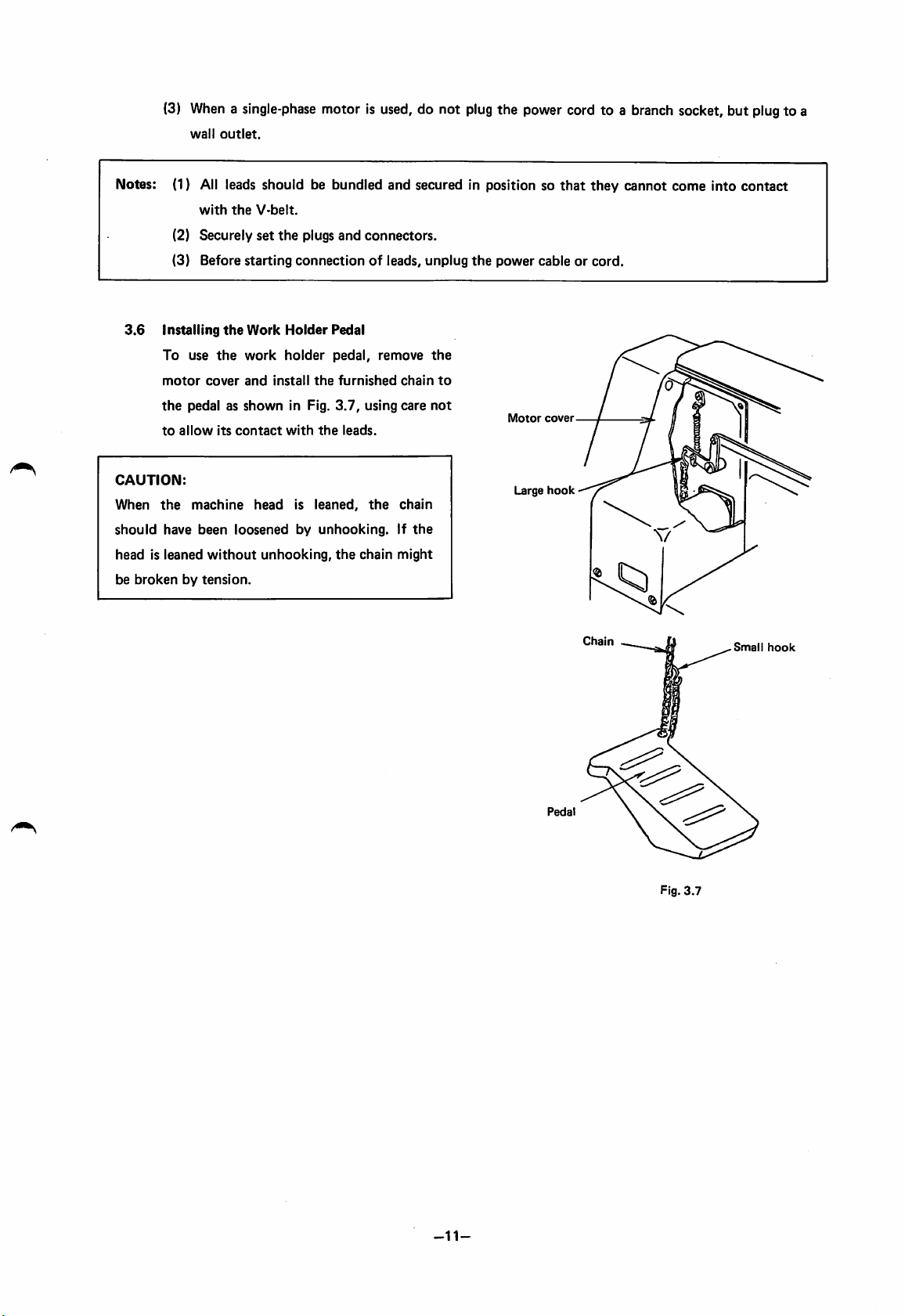
3.6
installing
To
use
motor
the
pedalasshown
to
allow
CAUTION:
When
the
machine
should
have
headisleaned
be
brokenbytension.
cover
been
without
set
the
the
its
the
contact
starting
Work
work
and
install
head
plugs and
connectionofleads,
Holder
holder
the
in Fig.
with
the
is
leaned,
Pedal
pedal,
furnished
3.7,
leads.
connectors.
remove
using
the
loosenedbyunhooking.Ifthe
unhooking,
the
chain
chain
care
chain
might
unplug
the
to
not
the
power
Motor
Large
cable or
that
they cannot come into contact
cord.
cover
hook
Pedal
Chain
Fig.
3.7
Small
hook
-11-
Page 16
4. PREPARATION AND CAUTIONS
(1)
Make
(2)
(3)
(4)
(5)
surethe source
Make
sure the
cassette
Move
and
work
holder.
Make
surethe
Check
the
To
check,
slot.
locate
LIMI-STOPZmotor
turn on the
PROM
the
presser
voltage
work
meetsthat specified for the
cassette in
holderbyhand
foot isset up so that the
power,
which
for
directionofrotation.
depress
lower the work holder and set the
refertosection
While
holding
The
pulley
correct
Direction
When changing
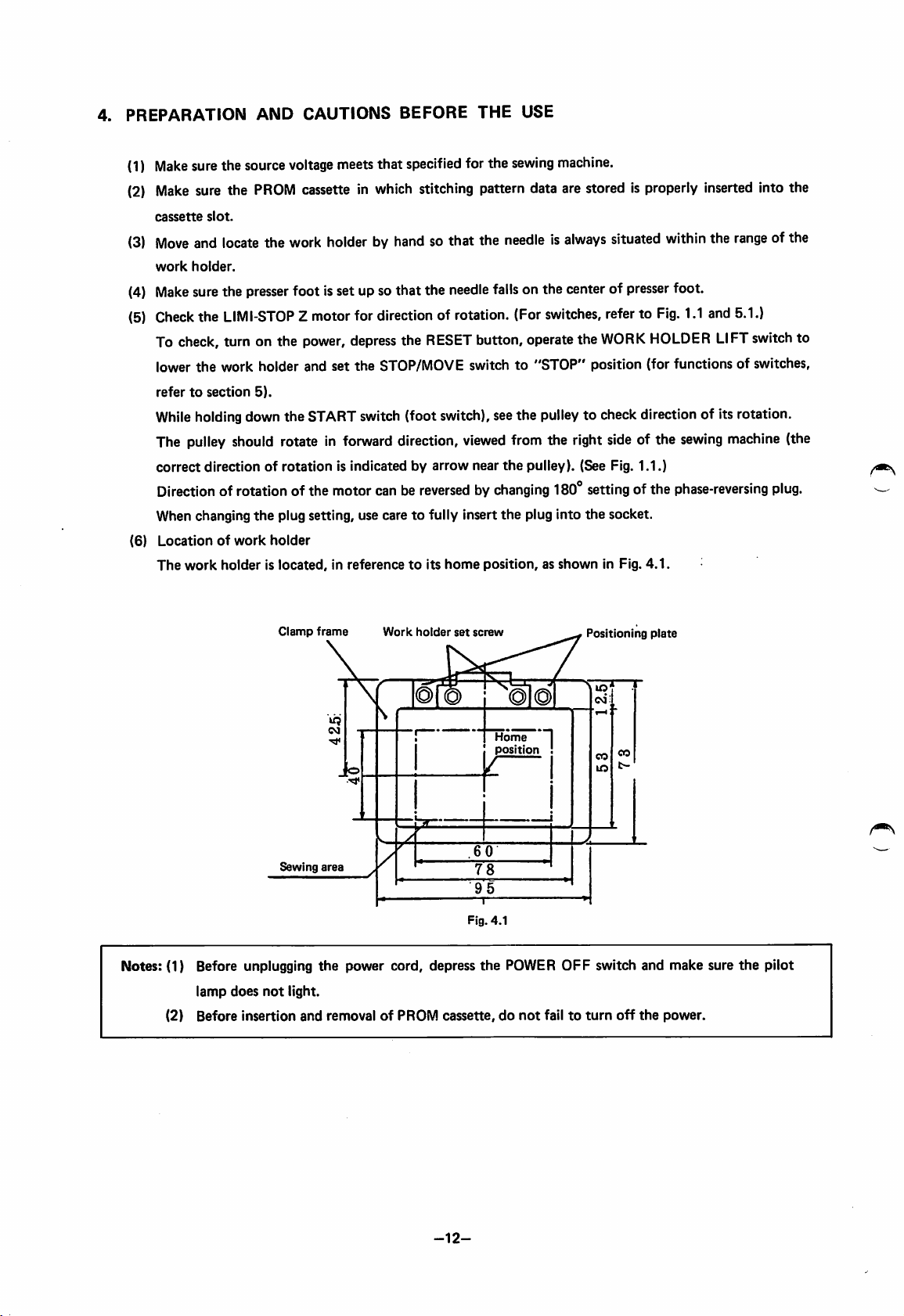
(6)
Locationofwork
The
work
directionofrotationisindicatedbyarrow
5).
down the STARTswitch(foot switch),seethe pulleyto check directionof its rotation.
should
rotate in
forward
of rotationof the motor canbe
the
plug setting, use care to fully insert the plug into the socket.
holder
holderislocated,inreferencetoits
BEFORE
THE
USE
sewing
machine.
stitching pattern data are stored is properly inserted into the
sothat the
needle
the
RESET
STOP/MOVE
direction,
reversedbychanging
home
needleisalways
fallson the center of
(For
switches,
button,operate the
situated
presser
refertoFig.
WORK
HOLDER
within
foot.
1.1
the
and
LIFT
switch to "STOP" position (for functions of switches,
viewed
from the right sideof the
near
the
pulley). (See Fig.
180®
position,asshown
settingofthe
in Fig.
sewing
1.1.)
phase-reversing
4.1.
range
5.1.)
switch
machine
ofthe
to
(the
plug.
Clamp
Sewing
Notes: (1) Before unplugging
lamp
does
not
light.
(2)
Before
Insertion
frame
area
the
power cord, depress
and
removalofPROM
Work
holder
set
Fig.4.1
cassette,donot
screw
Home
position !
the
POWER
failtoturn
Positioning
I
OFF
switch and make sure
off
the
plate
power.
the
pilot
-12-
Page 17
5.
CONTROL
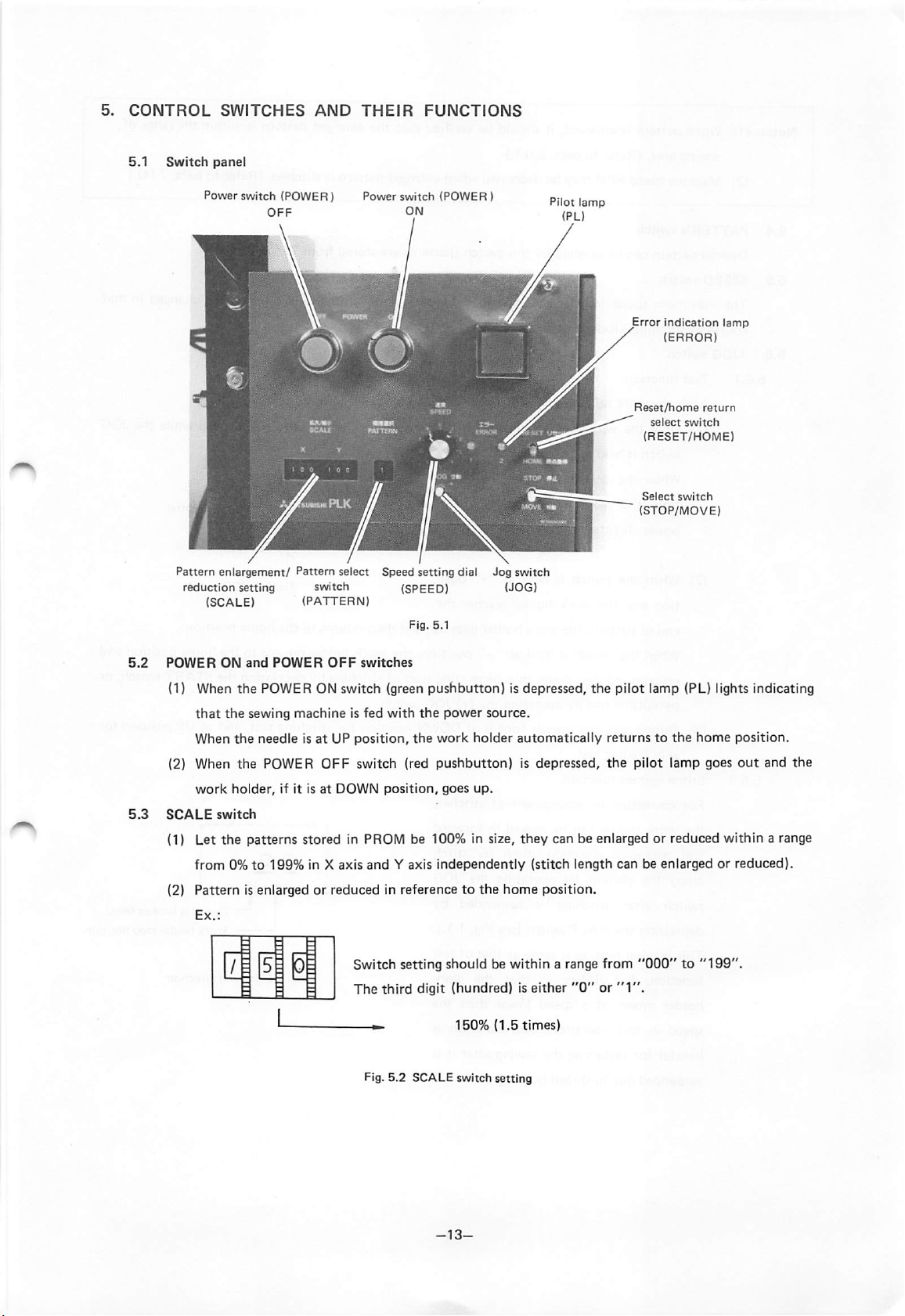
5.1
Switch
SWITCHES
panel
AND
THEIR
FUNCTIONS
Power switch (POWER]
OFF
Pattern
enlargement/
reduction setting switch (SPEED) (JOG)
(SCALE)
Pattern
(PATTERN)
select
Power
switch
Speed
ON
setting
Fig. 5.1
(POWER)
dial
Jog
switch
Pilot
(PL)
lamp
Error
Indication
(ERROR)
Reset/home
select
switch
(RESET/HOME)
Select
switch
(STOP/MOVE)
lamp
return
5.2
5.3
POWER
(1) When
(2) When
SCALE
that
When
work
switch
ON
and
POWER
the
POWER ON switch (green
the
sewing
the
needleisatUPposition,
the
POWER
holder,
if it isatDOWN
OFF
machineisfed
OFF
switches
with
the
switch (red
position,
pushbutton)
the
power
work
holder
pushbutton)
goes
up.
is depressed,
source.
automatically
is depressed,
the
pilot lamp (PL) lights indicating
returnstothe
the
pilot lamp goes
home
(1) Let the patterns stored in PROM be 100% in size, they can be enlarged or reduced within a range
from
0%to
199%
in X axis
(2)
Patternisenlargedorreducedinreferencetothe
/i^
and
Y axis
independently
Switch setting should be
The
third
digit (hundred) is
—
Fig.
5.2
150%
SCALE switch setting
home
(1.5
(stitch
within
either
times)
length
position.
a range
"0"or"1".
canbeenlargedorreduced).
from
"000"to"199".
position.
out
and
the
-13-
Page 18
Notes:
5.4
5.5
5.6.
5.6.1
(1)
When
patternisenlarged,itshouldbeverified
sewingarea. (Refer to para. 5.6.1.)
(2)
Machine
PATTERN
Desired
SPEED
The
maximum
course of stitching. (Refertopara. 7 (4).)
±JOG
speed
switch
pattern
switch
canbeselectedbythis
speed
switch
Test
function
After
the
work
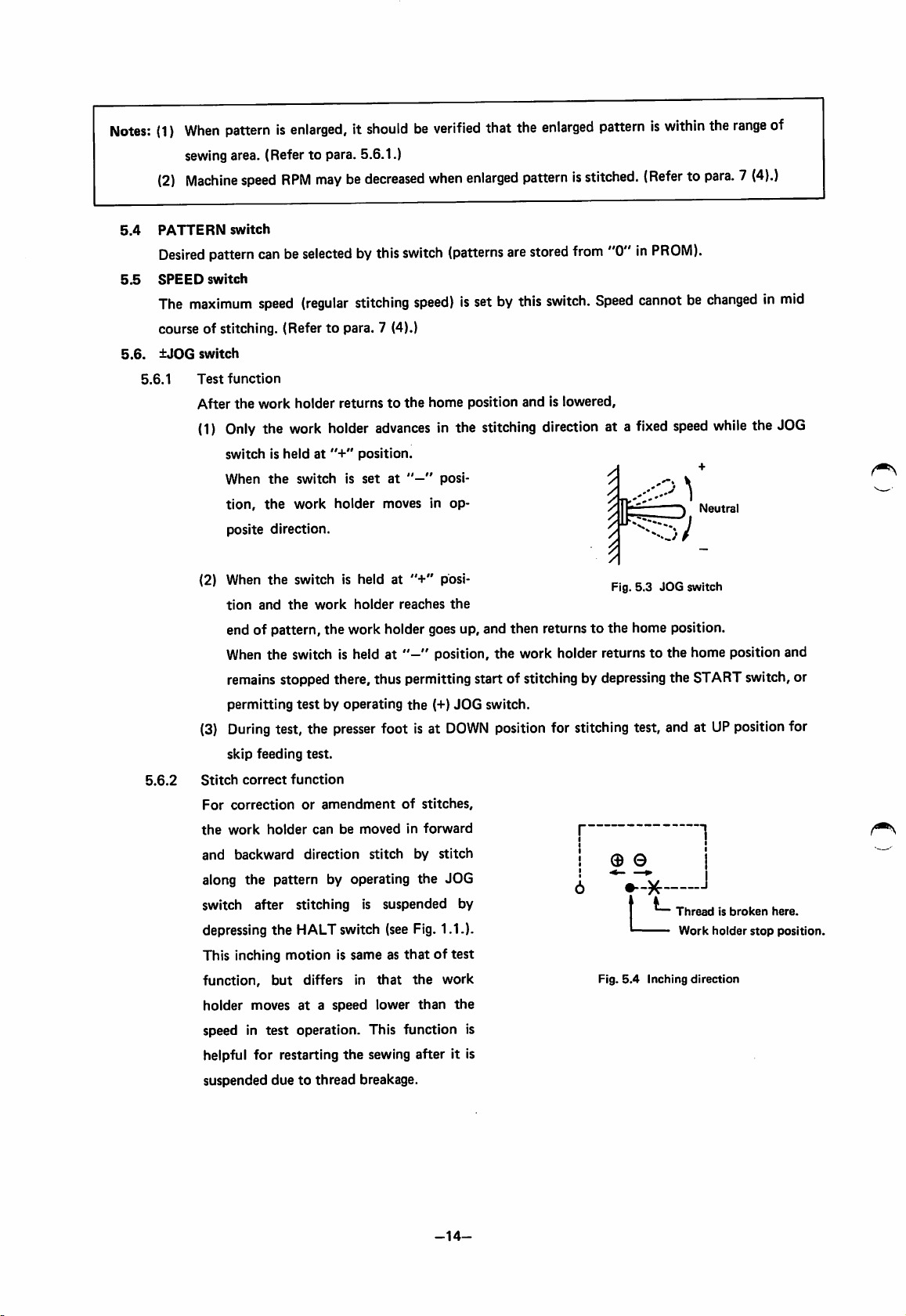
(1)
Only
the work holder
switchisheldat*'+"
When
the
tion,
the
posite
direction.
RPM
maybedecreased
(regular
holder
returnstothe
switchisset
work
holder
stitching
advances
position.
at
moves in
that
the
enlarged
when
switch
speed)
home
enlarged
(patterns
isset by
position
patternisstitched.
are
stored
this
switch.
andislowered,
in the stitching direction at a
posi
op
patterniswithin
from
"0"inPROM).
Speed
cannotbechangedinmid
fixed
the
range
(Refertopara.7(4).)
speed
while
the JOG
Neutral
of
5.6.2
(2) When
tion
the
switch is held at
and
the
work
holder
"+"
reaches
posi
the
Fig.
5.3
JOG
switch
end of pattern, the work holder goes up, and then returnstothe home position.
to
When the switch is held at " position, the work holder returns
the home position and
remains stopped there, thus permitting start of stitching by depressingthe START switch, or
permitting
(3)
During
skip
Stitch
correct
For
correction
the
work
and
backward
along the pattern by operating the JOG
switch after stitching is suspended by
depressing
This inching motion is same as
function,
holder
speed in
helpful
suspended
testbyoperating
test, the
feeding
holder
the
but
movesata
test
for
restarting
duetothread
presser
test.
function
or
amendment
can be moved in
direction
HALT switch (see Fig. 1.1.).
differs in
speed
operation.
This
the
sewing after it is
breakage.
foot is at
of
stitch
thatoftest
that
lower
function
the
stitches,
forward
by
the
than
(+)
JOG
DOWN
stitch
work
the
switch.
position for stitching test, and atUPpositionfor
| |
© ©
-K-
Threadisbroken
Work
holder
Fig.
5.4
Inching
direction
is
stop
here.
position.
-14-
Page 19
5.7
RESET/HOME
(1)
"RESET"
(2)
"HOME"
5.8
STOP/MOVE
The switch is
(1)
Bobbin
When
position
(2) Loweringofpresser
When
This switch setting is very helpful when
In usual operation,
5.9
Error
indication
The following
(1)
ERROR
Green
switch
switch
setat"STOP"
winding
the
START
the
sewing machine runsatabout
this
switchissetat"STOP"
"error"
1
No
position mostly for bobbin winding, and for lowering of
switch is depressed
foot
the
switch is setat"MOVE"
lamps light and operation stops when the following troubles occur.
pattern
dataisstoredorstored
When
the
switchisset
movementisreset.
When
the
switchissettothis
machine
movement
When
holder
(When
and
In usual
stops
with
is
reset.
the
switchisset
automatically
the
needleisataposition
the
work
holder
operation,
after
lowering
600
position,
the
the
presser
upward
position
the
needle
stoppedatUP
downward
returnstothe
returnstothe
the
switchissetat"HOME"
the
work
holder
spm,
but
the
work holder does
presser
foot
goes
foot
hinders threading.
position.
data
are
improper.
("RESET"
during
("HOME"
home
other
home
position),
stitching
position
position),
position.
thanUPposition,itgoes
position.)
position.
the
with
this
switch set at
not
down.
and
move at all.
Red Pattern is enlarged excessively and stitch length exceeds 6.2 mm.
(2)
ERROR
Green
(3)
ERROR1,ERROR
2
The
work
holder
runs
over
its movable range
2
-*•
Scale
down
the
pattern.
Two red lamps (ERROR 1 and ERROR 2) lighting on
The
needle is
Set
UP position, and
notatUP
the
RESET/HOME
position
switchto"RESET"
the
work holder
when
the
retumstothe
poweristurned
and
then
home
on.
"HOME"
position.
position.
The
needle goesupto
Two red lamps (ERROR 1 and ERROR 2) flickering
out
of pulley
5.10
The LIMI-STOP Z motor or sewing machine itself is locked or the belt is
-»•
Turn off the power, eliminate the cause of trouble and turn on the power again.
Work
holder
pedal
The work holder can be lifted or lowered by depressing this pedal (the height of work holder depends
on degreeofthe
The
5.11
Work
work
holder
pedaling).
holder pedal is very helpful when usedtoposition a given fabric.
lift
switch
The work holder goes down when this switch (pushbutton) isdepressed, and goes up when it isdepres
sed again. (See Fig.
1.1.)
all
machine
operation,
all
machine
the
work
presser foot.
"STOP"
the
up
-15-
Page 20

5.12
HALT
switch
Thisswitch isusedto suspendstitchingoperation
5.13
START
When
switch
(Foot
switch)
this switchis depressed,
sewing
(when
thread isbroken, for example),
starts from the home position.
(See
Fig.
1.1.)
(See
Fig.
1.1.)
-16-
Page 21

6.
OPERATION
6.1
6.2
6.3
inserting
Open
the
PROM
Cassette
the
switch panel front cover and Insert a PROM cassette In which necessary pattern data have
been stored Into the cassette slot, using care not to Insert It In wrong direction. After the Insertion,
Install
the
front
cover
again.
For
pattern
PTN-4000) Is necessary.
Switch
In
ordertocheck
To
check,
position
As
for
Switch
When
each
function
(1)
Home
Set
returnstothe
(2)
Work
The
the
(3)
Work
The
tion.
returntothe
to
When
occur.
By
performing
To
check
6.4.
writing
SettingonSwitch
each
set
the
SCALE switches (for X axis
ranging
the
Function
the
the
from
RESET/HOME
Checking
above-Instructed
as
follows:
return:
RESET/HOME
home
holder
lowering
work
holder
switchIsdepressed
holder
movement:
work
holder
When
the
work
home
"NEUTRAL"
the
above-mentioned
the
test,
stitching
condition,
and
erasuretoand from PROM, optional PROM writer (PT-100, PT-100A or
For
handlingofPROM cassettes, refertosection
Panel
function,
"0"to"9",
position
set
each
switchonthe
and
the
switch
and
the
STOP/MOVE
preparatory
switchto"RESET",
operation
(Refertopara.
SPEED
switch
and
Y axis)to"100",
switchto"4".
switch,
has
been
and
thento"HOME"tomake
5.7.)
panelasfollows:
set
completed,
them
11.
the
PATTERN
downward.
turnonthe
sure
power
the
switchtoany
work
motion:
shouldgodown
when
the
work
holder
lift
switch
Is depressed (It will lift
again.)
should
move
holder
position
reaches
(the
position while
testIsmade,
check
the
dimensions
set
stitching
tracting
work
the
the
given
the
endofthe
holder
work
holder Is tracing
only
the
and
locationofthe
speedto"low
pattern
pattern.Itshould
stops
andItdoes
work
holder
switch"
when
moves
work
the
JOG
switchIssetat"+"
lifttotheUPposition,
no go up
the
holder.
and
pattern).
and
when
the
(Refertopara. 5.6.)
stitching
proceedasInstructedInpara.
motion
switch Is
and
holder
does
check
when
posi
and
set
not
Note: In
on
order
to make yourself familiar with each switch function, It Is recommendedtooperate
the
switch
panel
without
needle
thread.
-17-
switches
Page 22

6.4
Sewing
Operation
{1) Referring to Fig. 5.1, properly set switches on the switch panel.
(2) Set up a
fabric
and
depress
the workholder lift
switch
to let downthe workholder.
the START switch, the sewing machine will start stitching. Once stitching starts, it continues even
when the START switch is released, and stops with the work holder at UP position after thread
trimming.
6.5
HALT
To
suspend
DOWN
Switch
stitching,
position
Operation
after
thread
depress
the
HALT
trimming.
switch
(Fig.
1.1). Stitching stops with the work holder at
To start stitching again, adjust the stitching start position by operating the JOG switch and depress the
START switch again. The sewing machine starts again and sews
the
remaining pattern.
Then
depress
-18-
Page 23

6.6
Operation
The
Checking
starting
sewing
before
operation
Procedure
machine
(1) Is
(2) Are all
(3) Is
(4)
and
Checking
shouldbeoperated
the
power
cable
source
outlet
and
other
cables properly plugged?
PROM
cassette
Are
fuses
not
blown
and
checkedinaccordance
properly
connector?
loadedonthe
plugged in
machine?
out?
power
with
the
CD
o
following
flow
chart:
Sectionorpara
graphtobe
to
Operation
Preparation
Judgement
referred
c
Set
neutral
Depress
switch.
work
Set
STOP/MOVE
"STOP"
Depress
lift
Preparation
the
pedal
position.
POWER
Does
LIMI-STOP
motor
Does
holder
its
home
position.
work
switch
start
to
ON
Z
start?
the
return
position?
switch
holder
><
No
No
to
to
Check
connection
Depress
switch
Set
"HOME"
Set
"RESET"
power
cable
POWER
RESET/HOME
position.
RESET/HOME
position.
I
OFF
>
switch
switch
to
to
Does
Check
of
direction
rotation.
Depress
switch.
Change
POWER
phase
ON
reversing
holder
down?
Does
start?
the
START
machine
work
Depress
switchto"ON
sewing
go
the
Depress
lift
switch
Depress
switch.
work
again.
POWER
holder
OFF
plug setting (180").
To
the
next
page
-19-
Adjust
holder
Check
motor
the
work
mechanism.
LIMI-STOP
cable
connection.
Z
Page 24

Adjust
setting
Depress
OFFsv*
Depress
switch
t
synchronizer
POWER
/itch
START
o
"OFF".
From
previous
speed
is
of
Depress
switchto"ON
the
atUPposition?
Set
STOP/MOVE
to
"MOVE"
the
Is
the
proper?
direction
rotation
correct?
START
Does
needle
page
stop
switch
position.
Depress
switch.
POWER
OFF
Adjust
the
synchronizer setting.
Test
operation
Depress
ON
switch
/
Check
\
cassette.
Depress
OFF
Set
RESET/HOME
to
"HOME"
Set
RESET/HOME
to
"RESET"
Set
JOG
"NEUTRAL"
POWER
PROM
POWER
switch
position.
switch
position.
to
position.
\
)
switch
switch
Set
PATTERN
(
Set
SCALE
(
No
switch
/ Set JOG switch to \
\ "+"
position.
Does
the
work
holder
move?
Ves
Is
work
properly
referencetothe
positioned
pattern?
Does
work
holder
go
up?
Preparation
completed
holder
)
>
/
Check
drive
Depress
POWER
switch
in
OFF
and
Adjust
mechanism.
control
mechanism
circuit.
work
holder
To
the
next
page
-20-
Page 25

Automatic
sewing
operation
Sewing
c
Set
stitching
<
^
Setupa
Depress
lift
switch.
start
fabric
work
)
speed^
(s)^
holder
Depress
lift
switch.
work
holder
^^-^abric
in p
Depress
Does
sewing
start
Depress
switchtoOFF.
Is
broken
stitching?
Are
trimmedatthe
of
he^v.
s<
scurely\.,_^
osition?x^
START
the
machine
running?
START
thread
during
threads
stitching?
Yes
end
No
PROM
data
input
error
Depress
POWER
OFF
switch.
Depress
HALT
Is
the
fabric properly
positioned?
Depress
START
switchto"ON".
switch
Adjust
by
operating
work
5.9
holder
JOG
position
switch
Does
wiper
work
properly?
Is
the
thread
trimmer
operation
satisfactorily?
Is
thread
tension
well
balanced?
-21-
Set
switch.
POWER
OFF
Adjust
machine.
the
sewing
Page 26

7.
CAUTIONS
(1)
Before
(2) If
any
ON
USE
replacementofPROMinPROM
alarm
(ERROR)
lamp lights,
cassette,
trace
its cause referringtothe
carefully
read
section
description
11.
in para.
5.9.
(3) When a new pattern is stitched for the first time, or pattern is enlarged, be sure to perform test to
check
(4) Sewing
The
maximum
However, it
relationship
maximum
between
speed
speed
the
dependsonstitch
automatically
shouldbeproperly
Table
7.1
work
holder
changes
set
for
individual fabric.
Relationship
and
stitch
movement
and
length.
dependingonstitch
between
length
sewing
the
pattern.
length,asshowninTable
(Refertopara.
maximum
7.1.
5.5.)
speed
Stitch
(5) Dust
(6) When
enteredinthe
cover
shouldbekept
the
control
close.
poweristurned
on,
(7) When adjustment is made on
to
the
mechanisms
(8) Do
not
apply a multimetertothe
in
the
circuit
(9) When single-phase
10 sec. until
or
control
mightbedamaged
motor
is used, do
the
motor
running is stabilized,
00
length
CO
I
5.4~6.2
CO
4.8-5.2
4.0~4.6
2.8-3.2
2.2~2.6
Less
unit
foot
the
box
mm
than
2.0
might cause malfunctionortrouble.
should
not
be placed on
sewing machine, be suretoturn
interior.
control circuit for checking or adjustment. Otherwise semiconductors
duetovoltage
not
from
the
immediately depress
after
switching on
Max.
speed
600
spm
850
1100
1300
1550
1800
2000
the
START
multimeter.
the
the
During
operation,
switch.
off
the
power before gaining access
START switch,
power.
but
the
control
wait for
box
about
-22-
Page 27

8.
NAME
OF
MAJOR
PARTS
OF
MACHINE
HEAD
Switch
Work
Cylinder
Face
HALT
holder
Eye
Presser
Presses
plate
cover
switch
guard
Wiper
foot
cover
lift
foot
switch
adjusting
Slide
r
plate
screw
Clamp
frame
Clamp
foot
Pretensioner
Work
spring
Thread
holder
tension
Qm
Slide
Top
plate
cover
Feed
plate
set
screw(4screws)
X
cover,
right
set
screw(2screws)
X-Y
cover,
Bobbin
Belt
right
winder
cover
Base
' Work
set
screw(2screws)
holder
Work
Positioning
(2
holder
plates)
plate
Fig.
8.1
-23-
Page 28

9.
HANDLING
9.1
THE
SEWING
Installation
of
Needle
(1) Before installing and removing
(2) Insert
(3) With
needle.
the
needle
the
needle prime groove
into
MACHINE
the
needle
HEAD
the
needle,
socket
unititstopsatthe
turnedtothe
turn
off
front,
the
power for safety.
bottomofneedle
tighten
socket.
the
needle set screw to secure
the
(4) For better stitching, though it depends on pattern, it is recommended to set the needle turned
about
10°inthe
Fully
turn
the
the
front
the
set
insert
prime
and
screw.
the
tighten
arrow
needle,
groove
direction.
to
Needle
inserted.
not
fully
Prime
direction
groove
facinginwrong
X
Fig.
9.1
9.2
Threading
The
from
9.3
Threading
The bobbin thread should be passed through the horn of bobbin case, as shown in Fig. 9.11, and
inserted
9.4
Removing
The
position,asshown
needle
the
into
inner
the
thread
needle.
the
the
hook
Needle
Thread
shouldbethreaded,asshown
Bobbin
the
Inner
Thread
hook
with
the
thread
Hook*
can
be removed by moving
in Fig.
9.13.
end
extended
the
in Fig.
2.5cmfrom
hook
clampinthe
9.2,
with
the
thread
end
extended
the
horn
hole.
directionofarrowtohorizontal
about
4 cm
-24-
Page 29

D6Dt
C B A
9.5
Lubrication
To
apply
felt
with
with
Silicone
silicone oiltothe
silicone
oil.
Face
Oil
plate
needle
thread,
Fig.
install
9.2
the
Thread
furnished
Needle
guide
thread
thread
with
guide having
felt
felt
and
dampen
the
Fig.
9.3
-25-
Page 30

Work
holder
Clamp
set
screw
frame
ly-|'
Length
|
A
Spring
Fig.9.4
bracket
Work
holder
shaft
Nut
9.6
AdjustmentofPressure
(1) To increase pressure, loosen
the
nut
(Fig. 9.4) and
turn
the
work holder shaft counter-clockwise
using a spanner (thereby length A becomes larger).
(2) To decrease pressure,
9.7
(3) With
Replacing
case,
the
decrease
the
(1) To replace
other
clamp
standard
Work
the
frame.
adjustment,
the
pressure.
Holder
clamp
turn
the
work holder shaft clockwise.
fabric(s)
Clamp
Frame
frame, remove
the
thicker
set
screws (Fig.
than
about
6 mm
8.1),
may
remove
the
not
be held
clamp
frame
(2) When replacing the clamp frame, do not loosen the positioning plate. Clamp frame can be ac
9.8
curately
Replacing
(1)
To
desired
(2)
The
installedbyreferringtothe
the
Feed
Plate
replace
feed
the
feed
plate,
feed
plate.
plate
shouldbeinstalledinreferencetothe
loosen
positioning
the
feed
plate
plate.
set
screws,
work
remove
holder.
the
feed
plate
down.Inthis
and
install
and
install
the
-26-
Page 31

9.9
Adjusting
{1)
{2)
the
Presser
Foot
Make sure the needle comes at the center of
the
presser
foot
hole.
Loosen the presser bar set screw (Fig. 10.10)
and adjust height of the presser foot so that
the
lower
mm
at
the
above
lowest
endofthe
the
position.
fabric
presser
when
the
(3) The vertical stroke of presser foot is factory-
adjusted to 4 mm. To increase the stroke,
remove
shown in Fig. 9.6
The
10
(4) To adjust pressure of
the
the
increases
wise,
clockwise. Fig.
adjustment. In usual operation, readjustment
of the auxiary adjusting screw Is
vertical
mm.
thumb
presser
and
the
switch cover, loosen
and
stroke
canbeincreased
the
nut
shown
foot
adjusting screw. The pressure
when
the
screwisturned
decreases
when
9.6
move it upward.
presser foot, loosen
in Fig.
turned
shows
foot
the
not
is 0 ~
presser
9.6
and
required.
0.5
bar
the
bolt
up
to
turn
clock
counter
standard
Presser
foot
set
screw
Presser
foot
is
0-0.5
mm
Fig.
9.5
Presser
foot
About
25
adjusting
mm
(Tumb
nut®
Thumb
screw
About
20
mm
Note:
Heightofthe
presser
depending on thickness of fabric.
9.10
Adjusting
(1)
(2)
the
Wiper
When
the wiper is not used, the wiper
position.
Height
of the
about 1.0 mm above the presser foot when the
at its highest position) by turning off the power.
Fig.
foot
shouldbechanged
wiper
shouldbeadjustedafter
9.7
Wiper
release
switch
release
switch
loosening
sewing
Fig.9.6
showninFig.
the
wiper
9.7 should be set at
set
screw
sothat the wiper
machineisstopped (with the take-up
Fig.
9.8
Wiper
set
screw
About1mm
T~a
forward
moves
lever
Note: When height or vertical stroke of presser foot is changed, height of wiper should be adjusted.
Page 32

9.11
WindingofBobbin
(1)
Pass
stand
thread
(2)
Set
position
(Refertopara.
(3)
When
MOVE
(4) If
the
wound
(5) It is
nylon
the
thread
as
shown
end
several
the
STOP/MOVE
and
the
threadiswound
switchto"MOVE"
the
threadiswound
thread
guide
thread
layers.
recommended
threadiswound
Thread
drawn
in Fig.
turnsonthe
depress
5.8.)
toward
that
out
from
the
9.9
and
wind
bobbin.
switch
the
START
up,
set
to
"STOP"
the
switch.
STOP/
position.
up conically, move
smaller
polyester
with
low
diameter
thread
tension.
cotton
the
of
or
/
Bobbin
Note:
9.12
When
should
Thread
Needle
the
threadiswound,
be
removed
Tension
thread
tension
the
from
the
needle.
shouldbebalanced
needle
thread
with
the
X
bobbin
Tension
adjusting
threadasshown
nut
below.
Fig.9.9
X
Thread
guide
Balanced
thread
and
thread
tension
bobbin
tension
needle
Fig.
-28-
Tight
thread
or
loose
thread
9.10
needle
tension,
bobbin
tension
Loose
needle
thread tension,
or
tight
bobbin
thread
tension
Page 33

(1)
Bobbin
The
cotton
thread
standard
thread
tension
bobbin
#60isthat
thread
the
tension
bobbin
gradually goes down when the thread end is
held by fingers and the bobbin case is
released.
To adjust tension, turn
adjust
screw
shown
(2)
Needle
thread
The
needle
thread
tension
in Fig.
tension
the
thread tension
9.11.
should
justed in referencetobobbin thread tension.
To adjust,
nut
shown
turn
in Fig.
the
tension regulator
9.12.
for
case
be
ad
thumb
Tension
Decrease
Fig.
adjusting
9.11
Tension
regulator
Decrease
Increase
thumb
screw
nut
Increase
9.13
Lubrication
(1)
Apply
(2) Pour lubricating oil
reaches
Oil filler hole ^ . Cover, left
Oil
gauge
several
dropsoflubricating oilto"A",
through
the
red
markonthe
the
oil filler hole in
oil gauge.
Hook
Note
clamp
that
Fig.
"B",
9.13
too
"C"
the
and
bed,
much
"D"
shown
oil
may
shown
in Fig.
spill
in Fig.
when
9.13,
the
9.2
until
Fig.
9.12
everyday.
the
oil level
headisleaned.
(3) Ifoil in the hook is excessive,remove the left cover, and one of two oil braid from the oil reservoir.
(4) Remove
oiltothe
the
X covers (left
retainer
shown
and
in Fig.
right)
and
feed plate, shown in Fig. 8.1,
10.27atleast
-29-
and
monthly.
apply several
drops
of
Page 34

10.
ADJUSTMENT
10.1
10.1.1
10.1.2
Machine
AND
head
Adjusting
Contact
can be
adjusted
loosening
Adjusting
(1)
Remove
shown
set
(2)
The
needle
upper
with
shown
MAINTENANCE
the
bobbin
pressure of
by removing
the
bobbin
the
heightofneedle
the
rubber
in Fig.
10.2,
screwtoadjust
standard
needle
barisat
timing
markonthe
the
lower
in Fig.
10.3.
winder
the
rubber
roller to
the
winder
set
screw.
bar
plug
from
and
loosen
heightofneedle
bar
heightisthat
the
lowest
needle
endofneedle
belt
cover,
the
face
the
position
bar is aligned
bar
the
plate,
needle
bar.
when
bushing,
pulley
and by
bar
the
the
Rubber
roller
as
as
Belt
cover.
Fig.
10.1
10.1.3
Needebar
set
Adjusting
screw
the
(1) After setting
inner
and
adjust
(2) To adjust, move
between
leftward
that
the
the
needle
Fig.
hook
hook
10.2
driver
and
the
the
and
bar
the
hook
the
driver.
the
driver
rightward
point
{Fig.
Fig.
10.3
clamptohorizontal position, as shown in Fig. 10.4, to remove
hook
retainer,
loosen
the
driver
set
screw
using a
hexagon
driver in forward or backward direction and position it so
and
needle
should
10.3)
becomes
direction.
cometothe
meets
the
zero.Atthe
The
standard
centerofthe
lower
positioninleftward/rightward
endofthe
same
time,itshouldbealso
needle
needle
when
bar
the
bushing.
lower
key
timing
Needle
bushing
wrench
that
adjusted
direction
mark
bar
the
gap
in
is
on
Page 35

(3)
The
same result can be
from
the
left
as
shown
in Fig.
side
surfaceofneedle
10.5.
A
obtained
when
when
the
hook
the
point
is positioned
hook
pointislocatedatthe
About
3.2
mm
about
3.2 mm
left
extremity,
apart
Page 36

10.1.5
Adjusting
the
thread
guide
(above
hook)
(Fig.
(1) Adjust the thread guide above the hook so
the
needle
side
surface.
If
this
(2)
Adjust
smoothly
Note
unbalanced
the
(3)
Since
largely
surface
adjustmentisimproper,
the
thread
guide so
pass
throughismade.
that
too
large gap may cause
thread
tension,
hook.
the
conditionofthe
affects
the
stitch
conditionissmooth
Thread
guide
set
thread
trimming
that
a gap
(standard
thread
uneven lengthoftrimmed
thread
quality
enough.
screw
and
guide
thread
10.7)
that
its left and right shoulders are aligned with
may
notbedone
gap:
0.8
trimming failure and
needle
surfaces
Shoulder
trimmer
with
performance,
mm)
which
Thread
properly.
that
thread
thread
guide
permits
too
carefully
needle
small gap may cause
and
jammingofthread
comes
into
check
set
screw
thread
contact
that
to
in
the
10.1.6
10.1.7
^.^nn
Adjusting
(1)
(2) Note
(3) Large
Replacing
(1)
the
work
holder
For
adjustment
that
faint
may
make
heavy
work
holder
the
work
For
replacementofclamp
procedure,
holder
(2) It is recommended
frame.
However,
when
the
the
positioning plate
work
holder
d
X
Thread
guide
pressure
refertopara.
work
holder pressure may cause slippageoffabric,
work
holder
movement,
pressure
that
may
require
clamp
frame
frame,
refertopara.
the
positioning plate is
must
bracket
position
Needle
Fig.
10.7
9.6.
causing
lower
misalignmentofpattern.
speed
than
9.7.
kept
tightened for easy replacement of clamp
be readjusted when
is changed.
Hook
retainer
specified in
the
home
but
too
large pressure
Table
7.1.
position is changed, or
-32-
Page 37

10.1.8
Adjusting
the
position of
work
holder solenoid
(1) Loosen the solenoid set screw shown in Fig. 10.8 and adjust solenoid position so
upper link is in contact with the stopeer when the solenoid is pulled (the plunger is in con
tact
with
the
solenoid
(2) Note that work holder pressure becomes extremely
the
linkislocated
Work
solenoid
bore
leftward.
holder
set
screw
bottom).
(See
Fig.
(See Fig.
10.9.)
Upper
10.9.)
link
small
and the work holder may go up if
Work
Stopper
solenoid
hoider
set
Plunger
screw
that
Work
solenoid
the
hoider
10.1.9
10.1.9.1
10.1.9.2
10.1.9.3
Fig.
10.8
Adjusting
Adjusting
(1) Timing of
shown
the
presser
the
in Fig.
foot
presser
presser
10.9.
Eccentric
foot
timing
foot vertical movement is
ring
governed
Eccentric
ring
set
screw
Fig.
10.9
by position of the eccentric ring
To adjust the timing, loosen the eccentric ring set screwand set the eccentric ring so that
the presser foot assumes the lowest position when the needle bar is at its lowest position.
(2) When the presser foot is at the lowest position the direction of the eccentric ring should
be perpendiculartothe
Adjusting
the
presser
illustrationofFig. 10.9, and face backward.
foot
vertical
stroke
(1) For adjustment procedure, refer to para. 9.9.
(2) Since the larger the vertical stroke, the larger is the noise and vibration, it is recom
mended to adjust
Adjusting
(1) Presser
the
a.
Turn
takeup lever at
crank
10.10) is parallel with the presser bar and then fix. (For this adjustment,
ring should have been properly adjusted.)
b.
Place
to the lowest position. Under this condition, adjust
foot
presser
foot
the
(right)
a fabric in position and turn the balancewheel by hand to locate the
(lower surface) is 0 —
the
stroke
as small as possible.
foot
height
height
during
stitching
balance wheel by hand with
the
highest position. Under this condition, adjust the upper feed lifting
the
sewing machine
shown in Fig. 10.8 so that the lengthwise center of
the
0.5
mm above the fabric and then tighten the presser bar
turned
bell
presser bar so
off
crank
that
to locate
the
eccentric
presser
the
(see
presser
the
Fig.
foot
Page 38

set
screw
(standard
To
prevent
be
made
smaller.
somewhat
becomes
downbythe
Since
affects
tightness
the
presser
is
recommendedtolower
smallaspossible.
When
presser
barathigher
the
presser
longer
prolonged
needle
and
the
fabricisnot
foot
presser
foottothe
larger
foot
adjustment).
stitch
skipping,
However,
and
when
presser
foot.
fabric
thread
the
fabric
causing
during
stitching,
position
footatthe
presser
fabric
the
holding
pattern
pressed
and
(2) Adjusting the lift of presser
this
gap
noise
becomes
holding
fabricispressed
time
adversely
tension
maybecaught
the
connecting
deviation,
presser
downbythe
set
adjust
bar.
foot
and
the
height
part
at stitching
should
time
seam
by
foot
presser
as
of
of
Bell
crank
pi
fl
it
Fig.
10.10
a.
Make
sure
the
adjustmentsoftiming,
Stroke and
stitching
b.
Lean
screw
With
set
the
the
shaft,asshown
rotary solenoid
While pulling
rotary
the
rod
4 — 7 mm below
height
are
standard.
the
machine
of presser
the
lifting
drive
of presser
head
foot
crank
cranksothat
in Fig.
(large)
the
drive
solenoidtomake
end
(right)
the
and
lifting
crank
(1)
setinthe
it is
10.11,
is not energized. B
crank,
sure
stopatthe
crossing line of
rotary solenoid axis center and the center of
the
rod
end
(left).
foot
loosen
fully
the
vertical
during
the
(2).
parallel
when
turn
center
position
set
shaft,
the
the
the
Presser
Presser
lifting
liftingcrank (1)
to
of
Rotary
^
foot
crank
(1)
solenoid
^
^ o ^ \
Set screw Presser foot ,
Set
screw
Presser
'lifting
Hlftlng
foot
crank
crank (2)
Fig.
10.11
Fig.
10.11
(large)
^
(2)
Stepped
c. With the presser foot at its lowest position lightly press down the lifting crank (2)
(pull
forwardinthe
Locate the lifting crank (2) so
the
stop
position
The lift of presser
clearance(2mm),
The
lift of presser
when
the
rotary
case
shown
and
secure
the
foot
at stitching
and
decreasedbymaking
foot
at stitching
solenoid is fully
in Fig.
10.11)byhand
that
the stepped bolt is positioned
lifting
crank
(2).
stop
can be increased by making smaller
it larger.
stopisthe
turned
with
the
untilitstops.
vertical stroke of
drive
crank
about
2 mm above
the
presser
fully pulled by hand.
this
foot
mpm
bolt
Page 39

10.1.10
Adjusting
the
thread
trimmer
(1) Adjust the cam follower so that the roller is found on the cam shoulder about 1 mm distant
from
the
thread
trimmer
<2)
Depress the cam follower crank in the direction of arrow shown in Fig. 10.12 by hand to
make
sure
the
roller can be engaged
(3) The roller engaging and disengaging area should be within
is
concentric
If
the
roller
with
cannot
shoulder, loosen the
(4)
contact
and
To
stop
plate
with
the
then
tighten
remove
the
the
knife
ring (circlip) shown in Fig.
shown
in Fig. 8.1 and
cam,asshown
the
arm
shaft.
be engaged and disengaged
nut
shown in Fig. 10.12, tighten the stopper screw until it comes into
cam follower crank
nut.
assembly,
four
and
loosen
10.13,
slide
in Fig.
disengaged
stopper,
E-type
feed
palte
set
10.12.
with
smoothly,
loosen
the
the
Stopper
cam
the
check
stopper
s(
groove
smoothly.
range where
that
the
screw by
I I —
the
cam groove
roller is on
about
1/3
Cam
the
turn
follower
Nu
crank
Cam
Cam
trimmer
Stop
groove
Abou'
groove
hole,
cam
thread
The
movable
canberemovedatthe
(5) To adjust
and
fixed
same
the
movable knife, loosen
knives
time.
knife position adjusting screw on
bed and adjust the knife drive crank so
movable knife
the
hook
retainer
point
when
stops
0.5
the
stitchingisstopped,
as shown in Fig. 10.13. (See Fig. 10.14.)
If
the
movable
knife is
located
and
mm
too
slide
the
the
apart
far
plate
movable
back
of
that
the
from
from
the
needle
satisfactorily,or the E-typestop ring strikes the thread guideset screwshown in
However,
tail might be
the
E-type
movable
caught
stop
knife located too
between
ring
the
Hook
fixed knife
retainer
close
and
to the
needle
the
movable knife.
hole, trimmed
Fig.
10.12
may
notbetrimmed
needle
Fig.
Shoulder
10.7.
thread
Arm
shaft
Movable
knife
Fig.
10.13
•Needle
Fixed
knife
hole
Fig.
10.14
Movable
adjusting
knife
screw
position
Page 40

10.1.11 Adjusting
(1)
Length
does not extend longer than about 22 mm from the bobbin case horn
may skip. In this case, the following checking and adjustment should be performed.
(2) Since trimmed thread contracts when bobbin thread tension is
thread is used, decrease bobbin thread tension and needle thread tension as well. For the
same reason, it is recommended to wind thread with smaller tension.
{3) When the clearance of Fig. 10.15 is more than 0.2 mm, thin thread may be cut before the
movable
To
distant
the
clearance
fixed
Fig.
Care
installed again
direction.
The
(4) Trimmed needle
shown
Thread tail length becomes
(5) For details, refertopara.
thread
stop
the
trimmed
thread
tail
length
of thread tail left on the bobbin after trimming isnot adjustable. If trimmed thread
{see
Fig.
9,11), stitch
too
large, or when elastic
knifeisactuated.
prevent
from
this, install
the
spacer below
of
0.2
knife
and
10.15.
shouldbetaken
that
notchonthe
in Fig.
10.16.
trimmer"
position...
the
fixed
needle
mm
the
reverse of
thread
plate
holeorremove
the
needle platetoprovide
or
smaller
needle
plate,asshown
when
the
it is
not
Installed in
needle
tail length can be adjusted by turning
short
10.1.5
10.1.12
"Adjusting
knife being
between
needle
plate
when
the
"Adjusting
the
the
plate
wrong
should
thumb
thread
In
Is
Notch
(on
of
be on
the
nutisturned
the
thread
release"
the
reverse Needle
needle
plate)
Fixed
knife
same
side as
the
clockwise.
guide..,
and
10.1.14
plate
Max.
0.2
Fig.
10.15
the
fixed
pretensioner
10.1.10
"Adjusting
"Adjusting
mm
knife.
thumb
the
nut
the
needle
Pretentloner
Fig.
10.16
»
Thumb
nut
Page 41

10.1.12
Adjusting
(1) If
(2) If the tension discs do
(3)
(4)
(5) Adjusting the tension disc release (opening degree of tension disc when the presser foot is
(6) Adjusting the tension disc release (opening degree
the
thread
release (tension disc pressure)
thread
stitch
becomes
When
from
discs
The
work
ON,orFEED
release is
may
skip or
faint
and
the
thread
releaseisproperly
0.8
mmto1.0
open,asshowninFig.
tension
discs
holderisat
without
trimmed.
lifted)
Lean
the
head
and
Fully
turn
the rotary solenoid (large) drive crank shown in Fig. 10.11tolift the presser
and adjust
arrow
in Fig.
the
position of
10.17,sothat
not
needle
thread
properly
thread
not
tensions
adjusted,
may
leave
close when the presser foot is lowered, needle thread tension
are
unbalanced.
adjusted,
mmisdeveloped
when
10.17.
open
when
the
presser
the
home
position
stitching),orwhen
loosen
the
needle
the
the
while
thread
tension regulator casing (B) in
tension
discs
trimmed
the
needle at
gop
ranging
the
tensionjp|jt:
foot
rises
(the
the
power
threads
tension
open
regulator
0.8
thread
tail length
startofsewing.
|=nn
J L
becomes
j t |
I| |
J
' ^ ^ j ' B
is
are
mm—1.0
set
✓•"n
screw.
the
direction indicated by
mm.
Fig.
Fig.
||
10.17
10.17
short
"[ijl
^
and
foot
10.1.13
Fully turn the rotary solenoid (small) crank in
the
direction
and
adjust
the
crank
tension
movable range of
clamping
Adjusting
• The wiper drive crank should be fixedtothe rotary solenoid shaft so
the left and
• Make sure
is turned by hand with the drive crank depressed backward in the direction perpendicular to the
illustrationofFig.
• Locate and fix the driven crank so
10.20
• For adjustment of height of the wiper, refer to para. 9.10 (2).
the
when
indicated
the
positionofthe
set
screw, so
disc
opening
the
screw
and
wiper
the
right, as shown in Fig. 10.19.
the
drive
crank
10.19.
the
wiperisreturnedtothe
by
arrow
tiiat
not
adjustable
drive crank, loosen
adjust
the
can
rotate
in Fig.
crank
after
the
position
through its
that
10.18
releasing
tension
start
discs
within
the
the
wire
Set
ofthe
wire.
entire
movable range
the wiper point is found at position shown in Fig.
position.
Set
screw
screw
that
it can swing evenly
when
Rotary
|
Rotary
Fig.10.I8
the
rotary solenoid
solenoid
solenoid
J
(small)
to
Page 42

Driven
crank
Fig.
10.19
10.1.14 Adjusting the needle bar stop (UP) position (Fig. 10.21)
the
(1) When stitching is completed,
arm being aligned with
(2) If
the
timing
screw
and
turn
marks
the
the
are misaligned over 3
couplingtoadjust
Stopping timing delays when
counter-clockwise.
(3) If
the
needle
bar
stopistoo
stitching.
If
the
needle
stop
delays,
by the needle,orthe
tirmmer
cannot
enter
the
movable knife does
the
cam
sewing machine should stop, the timing mark (A) on the
timing mark (B) on
the
mm,
the
needle
bar
the
coupling is
early,
needle
groove.
the
stopsata lower
needle
not
turned
thread
move since
Fig.
pulley.
loosen
the
synchronizer
stop
(UP)
position.
clockwise, and advances
may
leave
the
position
and
the
the
cam follower roller of thread
10.20
shaft
needle
wiper
coupling
when
set
turned
eyeatstart
mightbecaught
of
Synchronizer
Timing mark (A)
Fig.
10.21
Notes:
Although
Is
recommendedtomake
(1) Draw
die
out
needle
the
synchronizer cover
stop
(DOWN)
the
following
positionisnot
checking:
toward
the
requiredtobe
adjusted
cable (see Fig. 10.21).
Set
screw
cover
for usual
operation,
it
Page 43

(2) There are three position detecting discs in
tionofneedle
third
(3)
Turn
to
rotate).
one
the
DOWN
(blue)Isnot
first
disc (red)toalign
position,
in use.
the
second
the
matching
the
synchronizer: the first one (red) is for detec
one
(black) Is
holes, (hold
for
detection
the
circumferenceofthe
of UP
position,
and
the
first disc
10.1.15
Adjusting
(1) Install
that it
X-Y
the
home
the
does
detector.
home
not
Position
detecting
position
position
come
disc
into contact with the
irsp
detecting
^.
>•'-
Fig.
K
disc so
(2) The home position is established where
stepped
meets
(3)
The
the limitsof
When notches shown in Fig.
machine stops and
portion
the
centerofX-Y
X-Y
detector
of home position
(large)
movable
range.
"ERROR"
detector
detector
(small).
for detection
10.25
is provided in the home position detecting disc, the sewing
lamp lights when the notch is sensed.
10.22
the
^ome
position
detecting
X-Y
disc
^
detector
Fig.
Stepping
10.23
motor
Stepped
home
part
position
detector
of
(small)
Fig.
X-Y
10.24
detector
(large)
X-Y
detector
(small)
Fig.
Home
10.25
position
X-Y
detecting
Stepped
detector
disc
part
(large)
Page 44

(4) Although
electrically
20
mm
(5) When
the
sewing area is
12.1
(O.)
the
sewing area measures60mm by40mm in
controllable
eachinforward
sewing
and
area
backward
measures30mm
direction
from
terms
eachinleft
the
home
of mechanical restriction,
and
right
direction,
position.
home position is changed, as shown by bold arrow in Fig. 10.26 for example, the
restrictedtothe
Electrically
shaded
restricted
area. (Refertopara. 12.1 (C).)
30 I 30
< >{<
area
10
i'»
the
and
10.1.16
Mechanically
restricted
area
Fig.
10.26
(6) When the second home position is stored in PROM by using a PROMwriter PTN-4000, the
work
holder returnstothe
original
home
position when
home
return
operation
is done, and
the first stitching starts from the original home position, stopping at the second home posi
tion.
Thereafter, stitching starts
position.
Adjusting
(1) Adjusting
the
X-Y
table
the
positionofX-Y
a. Turn off the power and remove the needle, presser foot,
and
X covers (left
retainer
leftward and rightward. (See Fig.
end
strike
and
the
from
the
second
table
right). Then adjust
stopper
almostatthe
10.27
and
home
the
same
10.28.)
position, and
table so
time
when
that
endsatthe
X-Y
covers (left and right)
the
movable race
the
movable
second
race is
home
end
moved
and
b. If the retainer strikes the stopper earlier than the movablerace, let hit the retainer against
the
c.
stopper
Adjust
several
timestoadjust.
the
tableintheYdirectioninthe
same
mannerasinstructed
above.
d. When the movable race is moved, the travel of the retainer is equal to the half that of
the
e.
movable
When
area
fora
the
race.
stitching
long
time,
areaisexpanded
the
movable
race
after
may
stitching
not
move
has
been
smoothly.
doneIna
Inthis
case,
relatively
wipe
the
small
race
with a rag dampened with oil and move the movable race by hand to make the move
ment
smooth.
-40-
Page 45

(2)
Adjusting
pressure
a. To
adjust
the
X-Y
Y
covers
shown
X
covers
race
to
such
fixed
the
table,
in Fig.
set
screws
an
race (X)
X-Y
table
contact
pressure of
remove
(left
and
10.28
and
loosen
(X)(2screws)
extent
maybemoved.
contact
the
right)
and
fixed
that
Stopper
X-
the
the
Fig. 10.27 Whenmovable race islocated at the right extremity
Contact
X-Y
cover
(left)
pressure
adjusting screw (Y)
•35M
X
cover
(left)
Slide
plate
set
screw
10.1.17
b. X-axis
creases
are
c. Y-axis
Contact
d.
Adjusting
pressure adjusting screws (X)
contact
tightened.
contact
pressure
the
belt
pressure
when
two
contact
pressure
canbeadjustedinthe
should
be as light as possible, and
tensions (X-Y table)
in
Contact
pressure
screw
screw
adjusting
(x)(2screws)
(x)(2screws)(2screws)
same
Fixed
race
set
screw
(2
screws)
mannerasfor
not
cause
any
(X)
the
play.
Fixed
race
Fig.10.28
X-axis.
(X)
Fixed
race
(1) To adjust tension of the X-axis belt, remove the right X-Y cover (see Fig. 10.28), loosen the
nut shown in Fig. 10.29, loosen the four bracket set screws to such a degree that the bracket
can be moved and then tighten the belt tension adjusting screw (X).
(2) To adjust tension of the Y-axis belt, remove the belt cover and motor cover, loosen the
bracket set screw shown in Fig. 10.30 and tighten the belt tension adjusting screw (Y).
(3) The recommended belt tension is
finger.
that
no slack occurs when belt is lightly depressed by
(Y)
Page 46

Belt
adjusting
10.2
10.2.1
10.2.2
10.2.3
tension
screw
(X)
Ik
Fig.
10.29
Control
box
Cooling
fan
A cooling fan is installed on
If
the
fan
comes
(1) If
the
filter is clogged
tion
cannot
box
clean
the
(2)
To
clean,
screwdriver
(3)
After
the
slotsatfour
(4)
Since
the
contact
elementispressed
installed,
install.
Fuse
For
fuse,
each
See Fig.
Magnetic
Table
10.1
3.5.
breaker
shows
Bracket
set
intoastandstill,
be
assured
lever
up
and
remove.
cleaning,
corners.
fan
may
with
the
carefully
one
glass-tube fuse of
(Size of
the
fuse:
thermal
screw
the
with
and
Therefore,
the
fit
the
come
intoastandstill
filter
element
with
a large
press
06.4x30)
settingofthe
bottomofthe
electronic
dust,
good
temperature
outer
filter
outer
filter
if
force
the
filter
10A
control
box
componentsinthe
ventila-
in
the
using
a
into
key
due
to
the
filter
when
it is
frame
to
rating
and
20A
magnetic
breaker
for
control
rating is
(setatthe
cooling
used.
Fig.
10.30
the
control
box
For
box
mightbedamaged.
Fig.
10.31
locationofeach
factory).
interior.
'
'
m
fuse,
Page 47

10.3
LIMIT-STOPZmotor
10.3.1
Filters
Periodically clean the air filters at the end cover and on pulley side. (Note that cloggedair filter
may cause
10.3.2
Motor
The
the
Table
10.1
Power
Fig.
10.32
overheattothe
motor
is usually
motor.)
not
requiredtobe
Phase
Single-phase
Single-phase
Single-phase
Single-phase
Single-phase
Three-phase
Three-phase
Three-phase
Three-phase
overhauled.
Voltage
100
110
120
200
200-240
200
220
380
400-415
supply
(V)
Frequency
50/60
60
60
50/60
50
50/60
60
50
50
(Hz)
Thermal
setting
7.8
6.5
6.5
3.7
3.4
2.6
2.6
2.1
(A)
2.1
If stop position becomes inaccurate, rotation becomes unstable, or metallic sound occurs when
motor
is braked,
(1) Turn off the power to stop the motor. (About 2 min. is required until
check
the
motorinthe
following
order:
the
motor stops
completely.)
(2)
Remove
(3) Remove the cable plug (for brake) connectedtothe
(4)
Remove
the
three
belt
bracket
and
motor
mounting
pulley.
control box from the bracket.
screws.
(5) Remove the bracket. The brake assembly will be removed together with the bracket.
(6) Check the brake lining and brake disc for condition. If the brake lining is found worn out,
replace
(7)
Holding
ing can be removed together with
it.
the clutch shaft by hand, carefully pull it. The driven member (cup)and brake lin
If they cannot be
removed,
the
clutch shaft.
prepare two bolts
(M5
x 0.8 thread
length
of min.45
mm)
and
screw them into the tapped holes in the cup and boss (made of aluminum) to remove the
clutch
shaft.
(8) To
and
replace
bearing.
brake
When
lining,
the
remove
brake
the
liningisinstalled,
bearing
on the
align
pulley
sideand
the tapped hole
install
mentioned
a newbrake
at step (7)
lining
with holes in the brake lining. (Wheneverbearing is removed, install a new bearing.)
(9)
Assemble
each part in
reverse
steps to the disassembling. In assembling, if the clutch shaft
cannot be set in place,lightlytap the clutch shaft end with mallet. (Do not tap it strongly).
(10)
When
the brake lining is replaced, turn the clutch shaft by hand after
sure it can
smoothly
rotate
and
try
operation
for matching.
To match the brake lining, start the motor and depress the pedal at least
assembling
ICQ
times.
to make
Page 48

*Cautions
oDuring disassembling and assembling, carefully handle the brake cup avoiding its deformation
or
damage.
oSince bearing of special specification is used, addresstous when it is replaced.
10.4
Preventionofmalfunction
duetonoise,
and
grounding
(1) Malfunction caused by noise may be eliminated to a certain
synchronizer
(When
Leave
and
sewing
the
source voltage is larger
the
grounding
worktoqualified electrician.)
machine
head.
than
AC150V, grounding is indispensable
extent
by grounding
for
safety.
the
control box,
(2) Do not locate
frequency
welders.
the
sewing machine near equipment
that
generates intense noise, such as high-
Page 49

11.
REPLACING
THE
PROM
PROM is Installed in
the
socketonthe
printed circuit board
(RGB)
encased in
the
ReferringtoFig, 11.1 and 11.2, replace it as follows:
(1) Lever
(2)
{3) Remove
(4)
Take
Install
wise
out
out
the
the
cassette cover using a screwdriver.
the
P.O.
board
from
the
the
a new
PROM
PROM from
PROM
might
the
socket using a screwdriver.
in the socket.
be damaged.
cassette.
When
installing,becareful
not to
place
(5) Put the printed circuit board into the cassette and install the cassette cover.
(6) Use care not to directly touch the P.O. board terminals (pins).
(7)
When
removing
the
PROM
with screwdriver, care should be taken not to
It is recommended to use a ICremover (Type P-63, TAKARA TOOL S/S, for example).
(8)
Do
not
place
the
P.O.
board
and
PROM
on statically
sheet.
7='
charged
cloth or plastic, but
PROM
PROM cassette.
it in
wrong
direction, other
damage
the circuit pattern.
place
MarkingofIC
on a
metallic
pin
No.
1
Cover
D]
•
P.O.
board
:
PROM
P]
Fig.
11.1
Cassette
(9)
Optionally
expansion should be installed as shown in Fig.
11.3.
available PROM
cassette
for
memory
Lamp
No.
NotchofIC
on
1
P.C.
IC
board
O
socket
(PROM)
Fig.
terminal
11.2
should
side.
P.C.
Notch
board
come
^P.C.
terminals
board
No.
2
Fig.
11.3
-45-
Notch
Page 50

12.
AUXILIARY
FUNCTIONS
The DIPswitches SWi and SWj on the
CPU
card in the control box have
the
following functions:
(The switches are protected with transparent cover. After the setting, be sure to install the cover again.)
Transparent
cover
DetailsofSWI
^^joj
and
SW2
DOWN
(Switch
setat"OFF")
12.1
SWi
12.1.1
12.1.2
Fig.
12.1
Repeat
function
When
(§)
switch
isset at "OFF", only one pattern is stitched and the
UP
position
With
holder
However,itremains
the
START
lowered.
The
function
frameisused.
Home
(even
when
switch
setat"ON",
lift
switchisdepressedto"ON"
lowered
switch is
is very useful
position
return
Withd)switchofSWi
tion
when
the
POWERONswitchisdepressed
If
the
needleisnotatUP
sewing
machine
does
not
the
start
switchiskept
the
work
holder
and
when
the
stitchingiscompleted,
depressed
again.
Therefore,
whenapatternissewn
cancellationatpower
set at "OFF", the work
position,
start
when
however,
the
START
depressed).
goesupwhen
the
RESET/HOME
stitching
repeatedly,orwhen
turning
on
holder
and
the
needleisatUPposition.
the
ERROR
switchisdepressed.
work
the
poweristurned
switchissetto"REST"
and
stitching
canberepeated
automatically
lamps
"1"
returns
and
holder
stopsat the
on,
canberesumed
with
work
the
embroidery
to the home
"2"
(red)
light
the
owrk
position.
when
holder
clamp
posi
and
the
Page 51

In this case, let return the work holder by operating the RESET/HOME switch (refer to para.
5.7). The ERROR lamps will go
the
needle
goes
up.
With(Dswitch
needle is located, when
position
The
operated.
This function is usedtoavoid home position return at
otherwise
12.1.3 Enlargement/reduction (SCALE) cancellation
When
and
work
(§)
set at "ON", the
the
the
machine
holder can be returnedtothe
the
work holder may collide with
does
switchisat "OFF", the
out
and
the
ERROR
power is turned on. The work holder does
not
start.
enlargement/reduction
5.3) and sewing area measuring each 30 mm in left and right directions, and each 20 mm in
forward
By
trical restriction is imposed on the sewing area (refertopara. 10.1.15).
and
setting
backward directions is available. (Fig. 10.26)
@
switchto"ON",
the
enlargement/reduction
In this case, the pattern stored in the PROMis stitched in the real size (100%).
(§)
switchisprovisional,
and
has
nofunction.
work holder will return to
lamps
home
other
"1" and "2"
position when
the
part
of machine).
(red)
time
of pattern is
function
the
home position after
light,nomatter
not
returntothe
the
RESET/HOME switch is
the
power is turned on (when,
possible
canbereset,
(refertopara.
andnoelec
where
the
home
12.2
SW2
These DIP switches are usedtoset
Table 12.1 shows
(B)
switch is set at "ON" when the
timing
at each switch setting.
the arm shaft rotates by 4
synchronizer detects
When
(B) and (C) switches are set to "ON", for example, number of pulses becomesequalto 6 pulses
and therefore
Fabric feed timing can be checked as follows:
(1) With
(2) Depress the work holder lift switch to lower the work holder.
the
the
needle
feeding
needleatUP position,
start timing
Switch/Setting
(A)
"ON"
(B)
"ON"
(C)
"ON"
(D)"ON"
fabric feed timing.
sewing
machine is shipped, thereby
pulses
(one pulse corresponds to
DOWN
position.
delays
by 2
Table
12.1
Timing
8
pulses
4
pulses
2
pulses
1
pulse
turnonthe
pulses
(equivalentto11.2®
power.
feeding
5.6®
of arm shaft rotating
(3) Start the sewingmachine and depressthe HALTswitch while actual stitching is done.
(4)
While
the operation issuspended, lean the machine head and removethe V-belt.
(5)
Without
(6) Depress
the
V-belt, return
the
START
the
head.
switchto"ON".
of fabric starts when
angle)
of armshaft rotating
after the
angle).
-47-
Page 52

(7) By turning
(8) Since the work holder movement corresponds to fabric feed timing, visually check the timing in
referencetoheightofthe
(9) In several seconds after the START switch is set to "ON", the ERROR (alarm) lamp lights
(indicating that the V-belt is out of position) and the
engaged. However, it is OKto keep checking by turning the balance wheel by hand.
the
balance wheel by hand,
needle.
the
work holder Is driven by the stepping motor.
LIMIT-STOP
Z motor clutch will be dis
-48-
Page 53

Wiper
SOL
Work
holder
SOL
CON
14
CON
Switch
panel
CON
32
CON
11
CON
16
LZI
10
CON
•
3
CON4
PLK-ID-CPU
PCB
CON
CON7
83
CONl[]
CONS
PLK-1
-CS
PROM
cassette
PCB
J.
(O
POWERONswitch
POWER
Phase
reversing
LI
MI-STOP
Z
motor
CON
401
OFF
switch
PL. I
plug ' I
CON
, I 36
—U.
!-•—'
13
CON
CON
CON
Tramsformer
9
3 9
Transformer
TR2^.
CON31n
CON15Drn
C0N2[]
CON
PLK-50
-PMD
24 I I
CON
20
CONS
HALT
CON
CON
CON
CON
CON
8
switch
Synchronizer
n
-Thread
release
kPresser
foot
switch
Thread
trimming
tension
SOL
SOL
SOL
Work
holder
switch
Sewing
machine
CON
22
34
Q
17
23
26
25
CON
CON
4 1
21
START
w ^
^ 5
» z
§ o
(D
3 Q
I.
=.
S
S; >
M 2
3
W
>
O
JJ
Magnetic
breaker
CON
CON
CON
CON
19
18
5
6
Power
cord
plug
Fig.
13.1
Page 54

Details of
13.2
Motor
(1)
connectors
(All
connectors
For
three-phase
(200,
220,
are shown below.
viewed
from
connection
400/415V)
(For
location of each
lead
wire
side)
connector,
see Fig.
3.5
and
(380V)
Fig. 13.1)
CON
5
(1991-06P)
6 P
Connector
CON
(1991-06P)
White
Black
5
mm
Green
Black
(2)
White
For
single-phase
(100,110V)
White
Black
winding
mmr—o
Mam
winding
n 1
Green
Phase
(1991
connection
Red
reversing
-12P-2)
White
Back
Green
Blue
plug
Fig.
CONS
(1991-06P)
Black
6 P
13.2
CON
(1991-06P)
m
Connector
5
Green
White
i Green
(220,230,240V)
winding
mrrrr—o
Main
winding
Green
Phase
reversing
(1991-12P-2I
White
Green
Black
plug
6 P
Connector
(3)
For
clutch
and
CON33
(1991-04P-1)
(D
(D
(i>
Phase
brake
reversing
(1991-12P-2)
connection
plug
Fig.
Fig.
13.3
13.4
6 P
CON
18
m
3P
connuctor
(3191-03R1)
CON
19
I
2P
connector
(3191-02R1)
Connector
CL
+30V
BK
+30V
Clutch
Brake
rmr
coil
coil
Phase
(1991
reversing
-12P-2)
plug
-50-
Page 55

13.3
Stepping
Motor
CON34
(1360P)
sz:
©®©
©©^
®®
®
Connector
C0N2]
r
"(Green/whiteiXB
(White)
BCOM
(Green) XB
i(Black)
'2_-(Red/white)XA(Qreen/white)
I
I
i
I I
Connector
CON22
Fig.
13.5
(Red)
(White)
(Green)
Red
Black
Red/White
ACOM
XA
—-
BCOM
XB
XA
ACOM
Stepping
_
7"
(<
XA
motor
(X)
^ Steppingmotor
(Y)
13.4
13.5
Synchronizer
Start
switch,
C0N14
(1991-06P)
outer
CON
38
(1490P1)
(i>
Q>
Q>
presser
switch
(White)
(Black)
(White)
(Black)
UP
position
41
1.8K
AAA.
DOWN
position
Fig.
13.6
CON
(3191-02P1) (3191-02R1)
<D
1
•©
1
(D-
Outer
Synchronizer
presser
Start
switch
switch
Fig.
13.7
-51-
Page 56

13.6
SolenoidsinMachine
Head
13.7
HALT
CON
3 2
(1991-09P-1)
(D<^^
(D®®|
Switch
CON
41
(1545P-1)
Case
grounding
Fig.
+80V
+
+30V
13.8
30V
Machine
Machine
"3)
ft
o
1
8
a
Tor
resistanceofeach
head
head
Thread
Thread
tension
Work
Presser
Wiper
I
trimming
release
holder
foot
solenoid
solenoid,
solenoid
solenoid
solenoid
solenoid
refertopara.
10.9.
13.8
Stepping
CON
(Z)@®
rl€)©(I>
Motor
17
(1292P-1)
IZI
Position
Shielding
Detector
Home
position
detection
HALT
switch
(ZAP-2R:0MR0N)
fj
Fig.
13.9
Stepping
motor
position detect P.O.board (X) position detect
+E
(X)
GND
A—>
GND
©
Stepping
+E
Home
position
detection
I
I(Y)
motor
P.O.
board (Y)
I
Tobeconnected
(1545R-1)
to
Fig.
13.10
-52-
HALT
switch
Page 57

13.9
Flat
cable
connection
PLK-ID-CPU-h-PLK-1-CST
Connector
PS-50SEO-D4P1-1C
table
Table
13.1
CPU
10A
11A
12A
13A
14A
ISA
16A
17A
18A
19A
20A
21A
22A
23A
24A
25A
1A
2A
3A
4A
5A
6A
7A
8A
9A
Signal
name
GND
D4
03
05
02
06
01
07
00
A1
A2
AID
A3
GST-CHECK
A4
AS
A9
A6
A8
A7
CS1
CS2
+VCC
CST
IDA
11A
12A
13A
14A
ISA
ISA
17A
18A
19A
20A
21A
22A
23A
24A
2SA
CPU
1A
2A
3A
4A
SA
6A
7A
8A
9A
IB
28
38
48
SB
68
78
88
98 98
108
118
128 128
138
148
1S8
168
178
Signal
name
GNO
CSO
CS3
CS4
CSS
CSS
CS7
WR
AO
All
188
198
208
218
228
238
248
2S8
+VCC
CST
18
28
38
48
SB
68
78
88
108
118
138
148
1S8
168
178
188
198
208
218
228
238
248
2S8
PLK-1D-CPU
Connector
CPU
1A
2A
3A
4A
SA
6A
7A
8A
9A
10A
11A
12A
13A
14A
ISA
ISA
17A
18A
19A
20A
PLK-11
-PAL
PS-40SEO-D4P1-1C
Signal
GNO
ERR4
ERR2
JOG
XSCLS
YSCLS
YSCALE
YSCALE
YSCALE
YSCALE
YSCALE
YSCALE
YSCALE
YSCALE
XSCALE
XSCALE
XSCALE
XSCALE
name
(-)
Table
13.2
PAL
1A
2A
3A
4A
SA
6A
7A
8A
8
4
2
1
10
20
40
80
8
4
2
1
9A
10A
11A
12A
13A
14A
ISA
ISA
17A
18A
19A
20A
CPU
108
118
128
138
148
1S8
168
178
188
198
208
Signal
name
18
28
38
48
SB
68
78
88
98
GNO
ERRS
ERR1
JOG
(+)
RESET/HOME
STOP/MOVE
PSE
1
PSE
2
PSE
4
PSE
8
SPMAX
SPMAX
SPMAX
SPMAX
XSCALE
XSCALE
XSCALE
XSCALE
1
2
4
8
80
40
20
10
PAL
18
28
38
48
SB
68
78
88
98
108
118
128
138
148
1S8
168
178
188
198
208
-53-
Page 58

14.
TROUBLESHOOTING
If any
trouble
rate
troubleshooting.
(1) Is
the
power
Are
all
(2)
Are
?he
(3) Is
the
PROM
(See
the
(4) Does
(5) If
14.1
any
(If
any
any
fuse
(Two
fuses are used in
The
work
occurs
with
sourceatthe
connectors,
phase
connectorsinthe
cassette
pilot
lamponthe
ERROR
lampisfound
not
holder
properly
(alarm)
lighting,
blown
does
the
sewing machine,
specified
reversing
control
box
loadedinposition?
cassettetocheck.)
lamponthe
trace
out?
the
sewing
machine.)
not
returntothe
voltage?
plug
and
properly
panel
the
cause
the
following checking should be performed priortoelabo
switches
properly
set?
installed?
light
on?
and
remedy.)
home
position
when
the
poweristurned
on
14.2
Does
LIMI-STOPZmotoT
runingood
condition?
Is
needle
UP
position?
Does
work
ERROR
sound
motor?
holder
occurinstepping
The
Cause
(1)
The
power
cableisnot
(2)
LIMI-STOPZmotorisnot
(1)
V-beltisnot
(2)
at
Synchronizerisdefective.
(1)
Fuseisblown
(2)
Stepping
(1)
PROM
(2)
RESET/HOME
isat"RESET"
does
not
move
when
the
START
(1)
Safety
installed.
out.
motorisnot
cassetteisnot
position.
switchisoperated
meansistripped.
connected
connected.
connected.
loaded.
switchonswitch
..
panel
Refer
3.5
3.3
(3)
10.1.14
3.3
5.9
5.7
5.9
to:
(1)
Leads
are
not
(2)
(3)
SCALE
START
-54-
properly
switches
switchisdefective.
are
setto"0".
connected.
3.3
5.3
Page 59

14.3
14.4
Sewing
holder
Stitched
machine
Does
work
move
pattern
does
properly?
deviates
not
run
(1)
(2)
(1)
START
Machine
PROM
(Feed
switchisdefective.
mechanismislocked.
programming
without
error.
stitching is instructed.)
Refertothe
instruction
manual
DATA
DEVICE
of
INPUT
14.5
holder
Thread
Does
trimmer
Does
move
cannot
thread
solenoid
work?
(1)
work
properly?
Stitching
PROM
(2)
(3) X-Y
improper.
for
(1)
Synchronizer
speedistoo
Programming
feed
mechanism
(Check
smooth
motion)
needle
high.
error.
adjustment
the
mechanismbyhand
stop
position
is
adjustmentisimproper.
(2)
Fabricispartlyincontact
body
(particularly,inthe
with
machine
caseofhard
fabric).
be trimmed satisfactorily (the same is applied to the wiper and work holder) .
(1)
Any
lead
from
the
connected,ornot
(2)
Control
box
machine
connected.
trouble.
head
is dis
Refertothe
instruction
manual
DATA
DEVICE
10.1.4
3.3
of
INPUT
(1)
14.6
HALT (stitching suspension)
operation
Thread
is impossible
HALT
(1)
Any
(2)
or
Control
(3)
-55-
trimmer
switch
leadofHALT
not
connected.
box
mechanism
trouble
switchisdisconnected.
trouble.
trouble.
10.1.10
3.3
Page 60

14.7
14.8
14.9
Stitching
Stitching
Checking
Measure
The
resistances
speedisunusually
speedisunusually
the
Machine
resistances
Head
across
shouldbeas
low.
high
...
Connectors
pinsofeach
listed
below.
(1)
Torque
too
(2)
Synchronizer
(1)
Synchronizer
disconnected.
(2)
Synchronizer
adjustment.
connector.
requiredtodrive
large
duetodistorted
trouble.
pulse
troubleorimproper
the
mechanism.
generator
stitching
is
is
10.1.14
10.1.14
Wiper
Thread
andThread
release
Work
Presser
Note:
Solenoid
trimmer
tension
holder
foot
The
resistances listed
Table
Resistance
12
5
12
9.5
above
14.1
are
CON32
(Machine
Across5and
Across1and
Across7and
Across4and
those
measuredat20®C.
9-pin
pins
connector)
6
2
8
7
-56-
Page 61

(8309)
ROD
PrintedinJapan
A
MITSUBISHI
KCAO
OmCE
MfTSUeSM
ELECTRIC
OENKI BLOG MAftUNOUCKI TOKYO ICQ TELEX
CORPORATION
J34S32
CABLE MCLCO TOKYO
 Loading...