

Page 1
MITSUBISHI
^
Industrial
Sewing
INSTRUCTION
Single-Needle
Electronic
Model
Bar
Machine
MANUAL
PL
Lockstitch
K-0303
Tack
Machine
A
MITSUBISHI
ELECTRIC
Page 2
In
order
to operate
carefully
1.
2.
3.
and
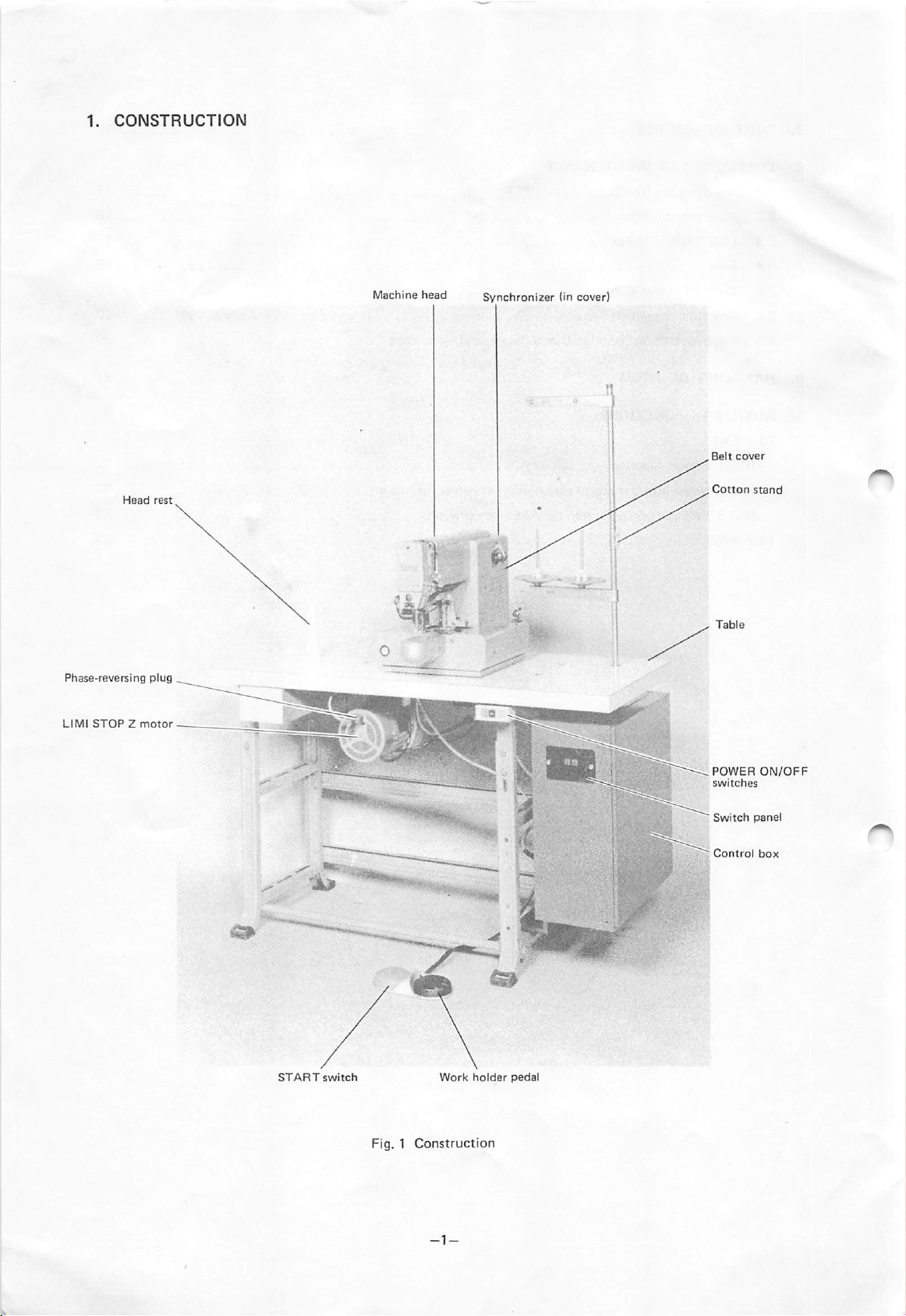
CONSTRUCTION
SPECIFICATIONS
INSTALLATION
3.1
3.2
3.3
3.4
3.5
4.
HANDLING
4.1
4.2
4.3
4.4
4.5
4.6
4.7
4.8
4.9
properly
installing
Connection
Work
Lamp
Power
Cable
Changing
Installation
Threading
Threading
Removing
Adjusting
Replacing
Winding
Thread
Lubrication
the
sewing machine in
handle
and
the
Machine
of
Leads
maintain
Head
the
best condition at all times, please read this Insturction Manual
the
sewing
machine.
-
CONTENTS
-
Leads
Connector
the
Power
Phase
Sequence
THE
SEWING
of
Needle
the
Needle
the
Bobbin
the
Inner
the
Pressure 8
the
Work
the
Bobbin
Tension
MACHINE
Thread
Thread
Hook
Holder
Thread
Clamp
HEAD
Frame
1
2
3
4
5
5
5
6
6
6
6
8
9
9
10
5.
6.
CONTROL
5.1
Switch
5.2
SCALE
5.3
PATTERN
5.4
SPEED
5.5
±JOG
5.6
STOP/MOVE
5.7
RESET/HOME
5.8
PR0M1/PR0M2
5.9
Error
5.10
Work
5.11
START
OPERATION
6.1
Switch
6.2
Switch
6.3
Sewing
SWITCHES
Panel
switch
Switch
Switch
Switch
Indication
Holder
Switch
Switch
Switch
Lift
(Foot
AND
Select
Switch
SettingonSwitch
Function
Checking
Operation
THEIR
Switch
Switch)
Panel
FUNCTIONS
11
11
12
12
12
12
13
13
13
14
14
15
15
15
Page 3
7.
CAUTIONS
8.
CHECKING
8.1 Adjusting
8.2
8.3
8.4
8.5
8.6
8.7
9.
HANDLING
10.
AUXILIARY
10.1
10.1.1
10.1.2
10.1.3
10.2
ON
USE
AND
MAINTENANCE
the
Needle Bar
Adjusting
LIMI-STOPZMotor
Fuse
CleaningofFan
Adjusting
the
the
Home
Filter
V-Belt
Position
Tension
PreventionofMalfunction
OF
PROM
FUNCTIONS
SW1
Repeat
function
Home
position
return
Enlargement/reduction
SW2
Stop
(UP) Position 17
DuetoNoise,
cancellationatpower
(SCALE)
and
Grounding
cancellation
turning
on
16
18
19
19
20
20
20
21
22
23
23
23
Page 4
,
Belt
,
Cotton
cover
stand
POWER
switches
Switch
ON/OFF
panel
Page 5
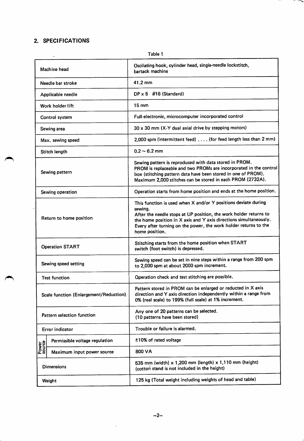
2.
SPECIFICATIONS
Table
1
Machine
Needle
Applicable
Work
Control
Sewing
Max.
Stitch
Sewing
Sewing
Returntohome
head
bar
holder
system
area
sewing
length
pattern
operation
stroke
needle
lift
speed
position
Oscilating
bartack
41.2
DP X 5
15
Full-electronic,
mm
mm
hook,
machine
#16
cylinder head, single-needle lockstitch,
(Standard)
microcomputer
incorporated
control
30 X30mm (X-Y dual axial drive by stepping motors)
2,000 spm (intermittent feed)
0.2~6.2
mm
....
(for feed length lessthan 2 mm)
Sewing pattern is reproduced with data stored in PROM.
the
PROM is replaceable and two PROMs are incorporated in
control
box (stitching pattern data have been stored in one of PROM).
PROM
Maximum 2,000 stitches can be stored in each
(2732A).
Operation starts from home position and ends at the home position.
This
function
sewing.
After
the
the
home position in X axis and Y axis directions simultaneously.
is used
whenXand/orYpositions
needle stops at UP position,
deviate
the
work holder returns
during
to
Every after turning on the power, the work holder returns to the
home
position.
Operation
Sewing
Test
Scale
Pattern
Error
k.
09
® o
|i
Q_
v>
mensions
D
Weight
START
speed
setting
function
function
selection
indicator
Permissible
Maximum
(Enlargement/Reduction)
function
voltage
input
regulation
power
source
Stitching starts from
switch
(foot
switch)isdepressed.
the
home position when START
Sewingspeed can be set in nine steps within a rangefrom 200 spm
to
2,000
spmatabout
2000
spm
increment.
Operation check and test stitching are possible.
Pattern stored in PROM can be enlarged or reducted in X axis
direction and Y axis direction independently within a range from
0% (real scale)to199%
Any
one
of 20
patterns
(10
patterns
Troubleorfailureisalarmed.
±10%ofrated
800
VA
535
mm (width) x
have
voltage
(full scale) at 1%
can be selected.
been
stored)
1,200
mm (length) x
increment.
1,110
mm (height)
(cotton stand is not included in the height)
125 kg (Total weight includingweights of head and table)
-2-
Page 6
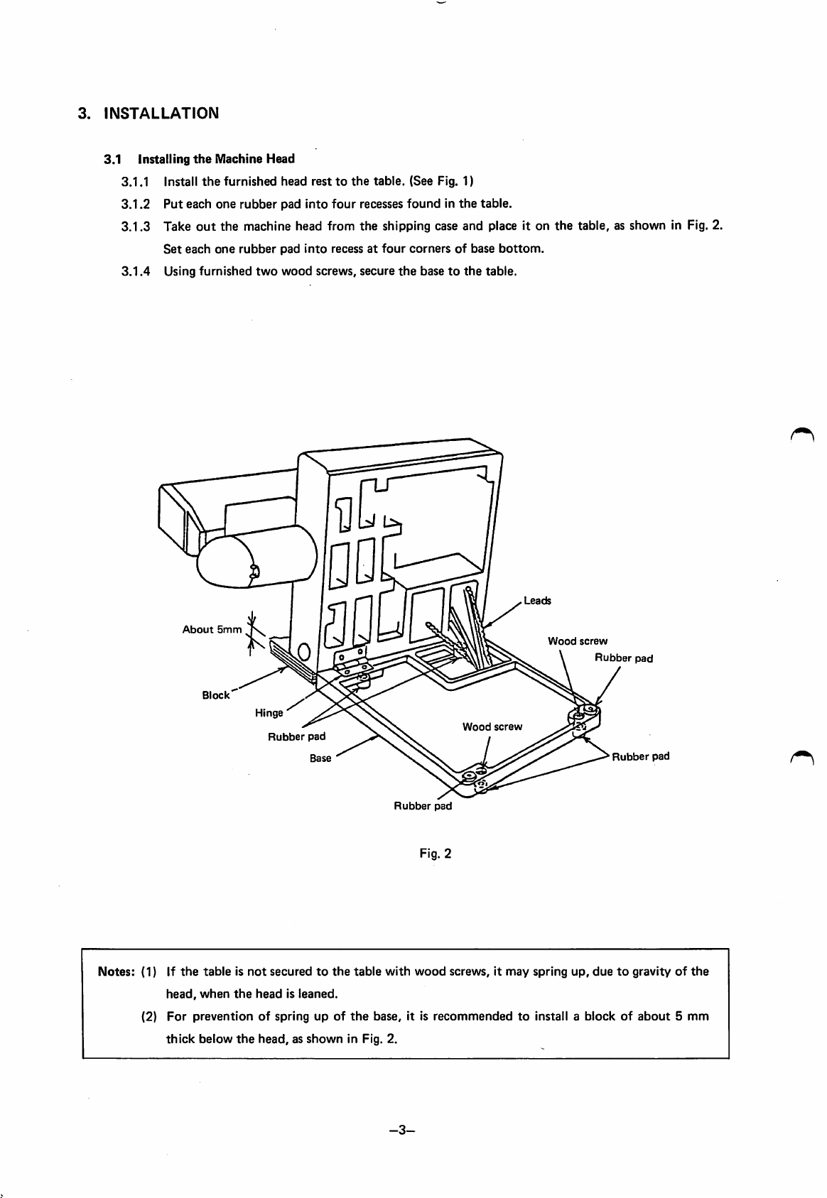
3.
INSTALLATION
3.1 Installing
3.1.1 Install
3.1.2
3.1.3
3.1.4
Put
Take
Set
Using
the
Machine Head
the
furnished head resttothe
each one
out
each
the
one
furnished
rubber
machine head from
rubber
two
pad Into
pad
into
wood
four
recesses
the
recessatfour
screws,
secure
table.
(See Fig. 1)
foundinthe
table.
shipping case and place it on
cornersofbase
the
basetothe
bottom.
table.
the
table, as shown in Fig. 2.
Notes:
(1) If
(2)
About
5mm
Block
Hinge
Rubber
the
tableisnot
head,
when
For
preventionofspringupof
thick
below
securedtothe
the
headisleaned.
the
head,asshown
QD
a
pad
Base
in Fig. 2.
table
the
with
base,
Wood
Rubber
pad
Fig. 2
wood
screws,itmay
it is
recommendedtoinstall a
screw
Wood
spring
screw
Rubber
pad
Rubber
pad
up,
duetogravityofthe
blockofabout5mm
-3-
Page 7
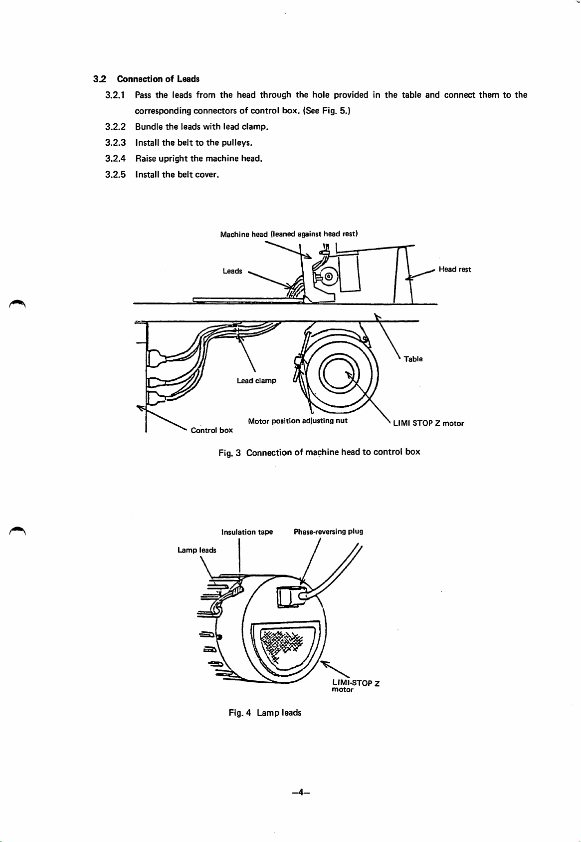
3.2
Connection
3.2.1
3.2.2
3.2.3
3.2.4
3.2.5
of
Leads
Pass
the
leads
corresponding
Bundle
the
leads
Install
the
belttothe
Raise
upright
Install
the
belt
from
the
head
through
connectorsofcontrol
with
lead
clamp.
pulleys.
the
machine
cover.
head.
the
box.
hole
providedinthe
(See Fig. 5.)
table
and
connect
themtothe
Machine head (leaned against
Leads
Lead
Control
Motor
box
clamp
position
adjusting
head
rest)
nut
Fig.3 Connectionof machinehead to control box
Head
Table
LIMlSTOPZmotor
rest
Lamp
leads
Insulation
Fig. 4
tape
Lamp
Phase-reversing
leads
-4-
plug
LIMI-STGP Z
motor
Page 8
OOOl
oeooj
iggglaaza
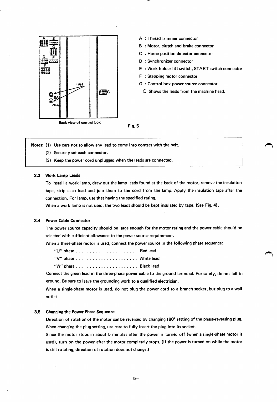
Back
viewofcontrol
box
Fig. 5
A :
Thread
B :
Motor,
C :
Home
D :
Synchronizer
E :
Work
F ;
Stepping
G :
Control
O
Shows
trimmer
clutch
position
holder
motor
box
the
connector
and
detector
connector
lift
switch,
connector
power
leads
brake
from
source
the
connector
connector
START
connector
machine
switch
head.
connector
Notes:
(1) Use
(2)
(3) Keep
3.3
Work
To install a
tape, strip each lead
connection.
When a
3.4
Power
The
selected
When a
Connect
ground.Besuretoleave
When a single-phase
outlet.
care
Securely
the
Lamp
work
Cable
power
with
three-phase
"U"
phase
"V"
phase
"W"
phase
the
nottoallow
set
each
power
cord
Leads
work
lamp,
For
lamp,
lamp is
Connector
source
capacity
sufficient
motor
green lead in
any
leadtocome
connector.
unplugged
draw
out
and
join
themtothe
use
that
having
not
used,
the
should
allowancetothe
is used,
the
three-phase
the
grounding
motor
is used, do
when
the
lamp leads
the
two
be large
connect
into
the
leads are
cord
specified
leads
shouldbekept
enough
power
the
power
worktoa
not
plug
contact
foundatthe
from
rating.
for
source
requirement.
power
sourceinthe
Red
lead
White
Black
cabletothe
qualified
the
power
with
the
connected.
backofthe
the
lamp. Apply
insulated by
the
motor
lead
lead
ground
electrician.
cordtoa
belt.
rating
following
terminal.
branch
motor,
the
tape.
and
remove
insulation
(See Fig.
the
power
phase
For
safety,donot
socket,
the
tape
4).
cable
sequence:
but
plugtoa wall
insulation
after
the
should
be
fail
to
3.5
Changing
Direction of rotation of the motor can be reversed by changing
When
Since
used),
is still
the
Power
changing
the
motor
turnonthe
rotating,
Phase
Sequence
the
plug
setting,
use
caretofully
stopsinabout5minutes
power
after
the
motor
directionofrotation
does
insert
after
the
completely
not
change.)
-5-
180®
the
plug
into
poweristurned
stops.
(If
the
setting of the phase-reversing plug.
its
socket.
off
(when a single-phase
poweristurned
on while
motor
the
is
motor
Page 9
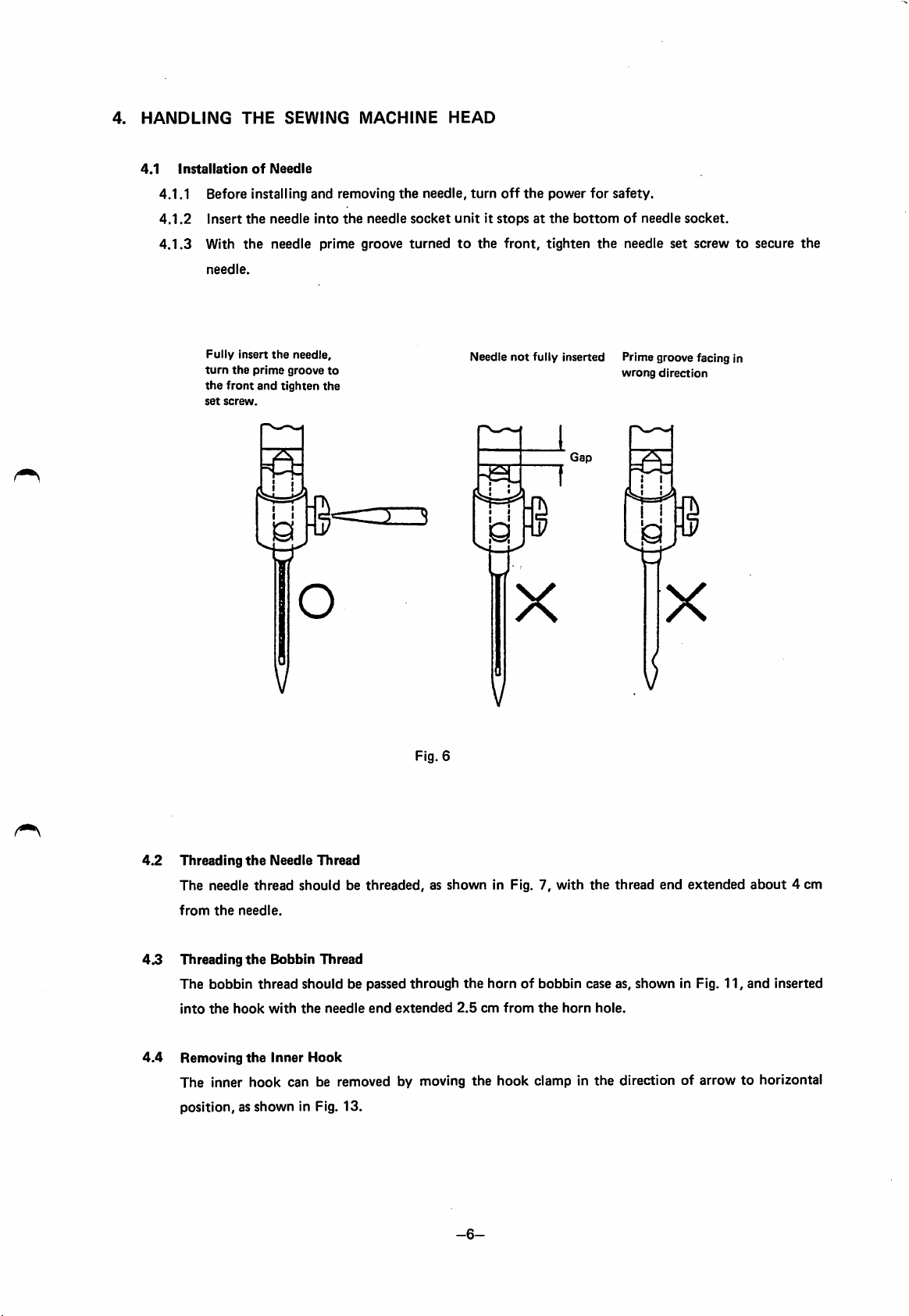
4.
HANDLING
4.1
THE
SEWING
Installation
4.1.1 Before installing and removing
4.1.2
4.1.3
Insert
With
needle.
Fully
turn
the
front
set
screw.
Insert
the
of
the
the
prime
and
Needle
needle
needle
the
needle,
groove
tighten
into
prime
to
the
MACHINE
the
needle
groove
2_3
d
HEAD
the
needle,
socket
unititstopsatthe
turnedtothe
turn
off
front,
Needle
N=H
I I
the
power
for
safety.
bottomofneedle
tighten
not
fully inserted Prime groove facing in
1
Gap
the
needle
wrong
socket.
set
direction
screwtosecure
the
4.2
4.3
Threading
The
needle
from
the
Threading
The
bobbin
into
the
the
needle.
the
hook
o
V
Needle
Thread
thread
shouldbethreaded,asshown
Bobbin
thread
with
Thread
should
the
needle
be passed
end
Fig. 6
through
extended
V
X
V
in Fig. 7,
the
hornofbobbin
2.5cmfrom
the
with
horn
the
thread
case as,
hole.
end
shown
X
in Fig.
extended
11,
about
and
4 cm
inserted
4.4
Removing
The inner
the
Inner
Hook
hook
can be removed by moving
the
hook
clamp in
the
direction of arrow to horizontal
position, as shown in Fig. 13.
-6-
Page 10

I
a
Fig. 7
-7-
Page 11

Work
holder
set
Clamp
screw
frame
Pressure
Fig. 8
spring
socket
Work
holder
shaft
4.5
4.6
Adjusting
4.5.1
the
Work
Holder
To increase pressure,
Pressure
loosen
clockwise using a spanner (thereby length
4.5.2
To
4.5.3
4.5.4
Replacing
To
a
decrease
With
work
replace
desired
pressure,
the
standard
holder.Inthis
the
Work
Holder
the
clamp
clamp
frame.
turn
adjustment,
case,
Clamp
frame,
the
the
decrease
remove
nut
work
fabric(s)
the
Frame
the
shown
holder
pressure.
set
screws
in Fig. 8
"A"
becomes larger).
clockwise.
thicker
than
shown
and
turn
the
about
6 mm
may
in Fig.8,remove
work
holder
notbeheld
the
clamp
shaft
downbythe
frame
and
counter
install
-8-
Page 12

4.7
Winding
4.7.1
4.7.2
4.7.3
4.7.4
4.7.5
the
Bobbin
Pass
the
thread
stand,asshown
Set
the
STOP/MOVE
position
and
(Refertopara.
When
the
threadiswound
MOVE
switchto"MOVE"
If
the
threadiswound
the
thread
guide
wound
thread
It is
recommended
nylon
threadiswound
Thread
drawn
in Fig. 9.
depress
5.6.)
toward
layers.
that
out
switch
the
up,
position.
up
smaller
polyester
with
from
the
to
START
set
the
conically,
diameter
low
tension.
cotton
"STOP"
switch.
STOP/
move
thread
of
or
Bobbin
Thread
guide
4.8
Thread
Needle
Balanced
tension
tension
Tension (Fig.
thread
tension
o
needle
and
thread
bobbin
10)
shouldbebalanced
tread
Tight
or
tension
loose
with
needle
bobbin
Fig.
the
thread
10
bobbin
tension
thread
Tension
adjusting
threadasshown
nut
Fig. 9
below.
X
Loose
needle
tensionortight
thread
tension
n
thread
bobbin
-9-
Page 13

4.8.1
4.8.2
Bobbin
The
cotton
gradually goes down
held
released.
To
adjust
Needle
The
thread
standard
thread
by fingers
adjust
screw
thread
needle
tension
bobbin
#60isthat
tension,
shown
tension
thread
and
turn
in Fig.
tension
(Fig. 11)
thread
when
the
the
(Fig. 12)
justed in referencetobobbin
To adjust,
nut
shown
turn
in Fig.
the
tension regulator
12.
the
the
bobbin
11.
thread
tension
bobbin
thread
thread
should
for
case
end
case is
tension
be
ad
tension.
thumb
is
Tension
adjusting
Increase
Decrease
screw
Fig. 11
4.9
Lubrication
Apply several drops of lubricating oil to
Pour lubricating oil through
the
red
Note
markonthe
that
too
Oil
filler
much
hole
oil
oil
gauge.
may
the
oil filler hole in
spill
when
"A",
"B",
the
headisleaned.
Cover,
"C"
and
"D"
shown in Fig. 7 everyday.
the
bed, shown in Fig. 13, until
left
Tension
thumb
Fig.
12
the
oil level reaches
regulator
nut
Increase
Oil
gauge
Hook
clamp
Fig.
13
-10-
Page 14

5.
CONTROL
5.1
Switch
SWITCHES
Panel
Pattern
AND
enlarge/reduction
THEIR
FUNCTIONS
setting
(SCALE)
Error
lamp
indica^n
Terror)
Jog
switch
6.2
(±JOG)
Speed
Pattern
SCALE
setting
select
Switch
dial
(SPPED)
swich
X-SCALE
(PATTERN)
%
PATTERN
Fig.
14
Y-SCALE
PROM
MOVE
HOME
PROM
%
select
switch
ERROR
(PR0M1/PR0M2)
/(STOP/MOVE)
RESET
PROM
2
Reset/home
Select
switch
select
(RESET/HOME)
return
switch
(1) Let the patterns stored in PROM be 100% in size, they can be enlarged or reduced within a range
from 0% to 199% in X axis and Yaxis independently (stitch length isenlarged or reduced).
(2)
Pattern
Ex.
is enlargedorreduced in referencetothe
Switch
• •
X-SCALE
%
L
range
The
third
"00"or"1
home
position.
setting
shouldbewithin
from
"000"to"199".
digit (hundred) is
150%
(1.5
a
either
times)
Fig, 15 SCALE switch setting
-11-
Page 15

Notes: (1) When pattern is enlarged, it should be verified
that
the
enlarged pattern is within
sewing area. (Refer to para. 5.5.1.)
(2) Machine speed RPM may be decreased when enlarged pattern isstitched. (Refer to Table 2.)
5.3
PATTERN
Desired pattern can be selected by this switch (patterns are stored from
5.4
SPEED
The
courseofstitching.
5.5
±JOG
5.5.1
Switch
Switch
maximum
Switch
Test
function
After
the
(1)
Only
stitching
the
When
the
direction.
(2)
When
and
pattern,
then
When
the
position
thus
pressing
ting
speed (regular stitching speed) is
work
holder
the
work
holder
directionata fixed
JOG
switchisheldat"+"
the
switchisset
work
holder
the
switchisheldat"+"
the
work
holder
the
work
returns
the
work
permitting
to
switchisheld
holder
and
remains
startofstitching
the
START
testbyoperating
returnstothe
advances in
at
moves
reaches
holder
the
home
at"
returns
switch,orpermit
the
speed
in
the
goes
to
stopped
(+)
JOG
home
position.
position,
opposite
position
up,
position.
position,
the
the
while
end
and
home
there,
by de
switch.
set
by this switch. Speed
position
of
andislowered,
Stitching
"0"
in PROM).
cannot
I
®^ j
start
position
Fig.16Directionofinching
the
range of
be changed in mid
1
operation
5.6
STOP/MOVE
The
switch is
(1)
Bobbin
When
position,
usual
Switch
setat"STOP"
winding
the
START
the
sewing machine runs at
operation,
position
mostly
switch is depressed
the
switchissetat"MOVE"
for
after
about
-12-
bobbin
lowering
600
spm,
position.
winding.
the
work
but
the
holder
work
with
holder does
this
switch
not
setat"STOP"
moveatall. In
Page 16

5.7
RESET/HOME
(1)
(2)
5.8
PR0M1/PR0M2
Switch
"RESET"
"HOME'
(1)
(2)
(3) If
PROMs
Fig.
10
PR0M1.
the
in
(When
17.
patterns
further
PR0M2
it.
are
patterns
the
patternisstoredinthe
(4)
This
switchisusedtoselect
(5)
PR0M1
pattern
Before
"9.
and
storedinthe
PROMisloadedorunloaded,
HANDLING
Select
found
have
and
sewing
PR0M2.
Switch
at
the
places
been
stored
by us in
mustbestored,
store
the
desired
machineisshipped,
PR0M2.)
PROM
Stitchingismade
OF
selected
PROM",
PROM.
without
When
the
machine
When
tion,
and
When
holder
(When
movementisreset.
the
the
machine
all
machine
the
automatically
the
goes up and
In usual
shown
between
operation,
in
the
remove
patterns
no
with
read
fail.
switch is
switchissettothis
switchisset
needleisataposition
the
set
rightward
stops
with
the
movement
is
reset.
leftward
returnstothe
work holder returnstothe
the
switch is
PROMl
("RESET"
position
during
needle
stoppedatUP
("HOME"
home
other
position.
than
setat"HOME"
\ /
•••
T/
v
Notch
P.C
board
position),
stitching
position),
UP
the
position,
home position.)
position.
PROM
2
1 1
1 1
o
all
opera
position
work
it
O
O
o
o
o
5.9
Error
Indication
The following
(1)
ERROR
"error"
1
lamps light and operation stops when
Green No
Red
(2)
(3)
ERROR
Green
ERR0R1,
Two
and
2
red lamps
ERROR
ERROR
(ERROR
2) lights on
2
1
pattern
Pattern
6.2
mm.
The
work
->•
Scale
The
needle is
Set
"HOME"
holder
-13-
the
following troubles occur.
dataisstoredorstored
is enlarged excessively
holder
runs
over
its
down
the
pattern.
not
at UP position
the
RESET/HOME switchto"RESET"
position.
returnstothe
The
home
goesupto
data
and
movable
when
position.
UP
Fig. 17
are
improper.
stitch
range
the
power is
position,
length exceeds
turned
on.
and
then
and
the
work
Page 17

Two
5.10
Work
red lamp (ERROR 1
and
ERROR
Holder
2) flickering
Lift
Switch
The
LIMI-STOP Z
the
beltisoutofpulley
cause of
trouble
motor
and
turnonthe
or sewing machine itself is locked or
-*•
Turn
off
the
power,
power
again.
The work holder goesdown when this switch (pushbutton) isdepressed,and goesup whenit isdepressed
again. (See Fig. 1)
5.11
START
When this switch is depressed, sewing
Switch
(Foot
Switch)
starts
from
the
home
position. (See Fig. 1)
eliminate
the
-14-
Page 18

6.
OPERATION
6.1
6.2
Switch
SettingonSwitch
In
ordertocheck
Set
the
SCALE
ranging
As
at
Switch
When
each
for
the
from
the
left
Function
the
function
each
switches
"0"to"9",
RESET/HOME
position (settingatshipping).
Checking
above-instructed
as
follows:
Panel
function,
(both
and
switch,
preparatory
set
for
SPEED
the
each
switchonthe
X axis
and
switchto"4".
STOP/MOVE
operation
switch
Y axis)to"100",
switch
and
has
been
completed,
panelasfollows;
the
the
(1) Home return: Set the RESET/HOME switch to
to
make
sure
the
work
holder
to
para.
5.7.)
(2) Work holder lowering
(3) Work holder movement:
When
the
above-mentioned
occur.
By
performing
the
test,
To check stitching condition, set stitching speedto"low
para.
6.3.
motion:
check
test is
the
dimensions
The
work
holder
is
depressed
The
work
JOG
the
endofthe
to
the
when
holderistracing
made,
(it will
holder
switchissetat"+"
home
position
the
switchissetto"NEUTRAL"
only the work holder
and
should go down when
lift
when
the
should move tracing
position.
pattern,itshould
(the
work
the
pattern).
(Refertopara.
moves
locationofthe
work
switch" and proceed as instructed in
PATTERN
PR0M1/PR0M2
turnonthe
"RESET",
returnstothe
switchisdepressed
When
lifttotheUPposition,
holder
switchtoany
switch,
power
and then to "HOME"
home
position.
the
work
holder lift switch
again).
the
given
pattern
the
work
holder
stops
anditdoes
position
while
5.5)
and stitching motion does not
holder.
position
set
and
when
reaches
and
not
the
them
check
(Refer
the
return
go up
work
Note: In
6.3
order
to make yourself familiar with each switch function, it is recommendedtooperate switches
on
the
Sewing
switch panel
Operation
without
needle
thread
before starting sewing work.
(1) ReferringtoFig. 14, properly set switches on
the
switch panel,
(2) Set up a fabric and depress the work holder lift switch to let down the work holder. Then depress
the
START switch,
Once stitching starts, it continues even when
work
holderatUP position
the
sewing machine will
after
thread trimming.
-15-
start
stitching.
the
START switch is released, and stops with
the
Page 19

7.
CAUTIONS
(1)
(2) If
(3) When a
(4) Sewing
ON
USE
Before
replacementofPROMinPROM
any
alarm
(ERROR)
new
patternisstitched
relationship
The
maximum
However, it
between
maximum
speed
speed
shouldbeproperly
the
automatically
Table 2 Relationship between maximum sewing speed and stitch length
lamp
lights,
trace
for
the
work
holder
dependsonstitch
changes
set
for
CO
Stitch
CO
length
cassette,
first
movement
carefully
its
cause
referringtothe
time,orpattern
and
length.
dependingonstitch
individual fabric.
read
section8."HANDLING
descriptioninpara.
is enlarged, be suretoperform
the
pattern.
length.
(Refertopara.
Max.
speed
5.4.)
OF
5.9.
PROM".
testtocheck
5.4~6.2
CO
4.8~5.2
4.0~4.6
2.8~3.2
2.2~2.6
Less
than
(5)
Dust
enteredinthe
cover
shouldbekept
(6) When
the
power is
(7) When adjustment is made on
the
mechanisms
(8) Do
not
apply a
in
the
circuit
control
close.
turned
on,
or
control
multimetertothe
might
be damaged
unit
might
foot
the
sewing machine, be suretoturn
box
interior.
duetovoltage
(9) When single-phase motor is used, do
sec. until
the
motor
running
is stabilized
mm
2.0
cause
should
not
control
circuit
not
immediately depress
after
600
spm
850
1100
1300
1550
1800
2000
malfunctionortrouble.
be placed on
the
START
off
During
operation,
the
control
switch.
the
power before gaining access to
for checking or adjustment. Otherwise semiconductors
from
the
multimeter.
the
switching on
the
START switch,
power.
but
wait for
about
box
10
-16-
Page 20

8.
CHECKING
AND
MAINTENANCE
8.1 Adjusting the Needle Bar
(1)
Adjust
needle
on
the
arm
when
(2) If the adjustment is
barstop
the
Stop
(UP) Position (Fig. 18)
(UP)
position sothat the thread holeof takeup
sewing
machineisstopped.
out
of alignment over 1 mm, loosen the synchronizer shaft coupling set screw
and turn the coupling to adjust the needle bar stop (UP) position.
Stopping timing delays when the coupling isturned clockwise,and advances when turned counter
clockwise.
(3) If the needle bar stops too early, the needle threed may
stitching.
If
the
needle stop timing delays, the needle stops at a lower position and the wiper might be
caught by the
trimmer
cannot
needle,
enter
or the
the
cam
movable
groove.
knife
does not
move
since
leverIsaligned
leave
the needle eye at start of
the
cam
follower
roller
withthemark
of thread
Notes: Although
recommendedtomake
1.
2. There are
3.
the
needle
Draw
out
the
three
of
needle
DOWN
one
(blueisnotinuse.
Turn
the
first
rotate
the
disc).
stop
(DOWN) position is
the
following
synchronizer
position detecting discs in
position,
disc (red)toalign
cover
the
checking:
toward
second
the
not
the
the
one
(black) is
matching
requiredtobe adjusted for usual
cable
(See Fig.
synchronizer:
holes
18).
the
for
detectionofUP
(hold
the
first one (red) is for
first disc on its
position,
operation,
detection
and
the
circumference
it is
third
to
Page 21

8.2
Adjusting
(1) Install
thatitdoes
X-Y
Position
the
Home
Position
the
home position detecting disc so
not
come
detector.
detecting
into
contact
(2) The home position should be established so
that
the
disc
stepped
meets
the
portion
center
of
of
(small).
(3) The X-Y detector (large) is for detection
at
the
limits
range.
When
notch
in
the
home
ing machine stops and
lights when
shownes
position
the
notch
of
work
detecting
holder
in Fig. 22 is
"ERROR"
is sensed.
the
X-Y
disc,
discj
Fig.
with
detecting
detector
movable
provided
the
19
the
sew
lamp
Position
detecting
Detector
disc
element
Fig.
20
Stepped
detecting
Detector element
portion
disc
of
,
(smalD^B
Detector element (large)
X-Y
detector
(small)
Home
position
detercting
X-Y
disc
detector
(large)
Page 22

8.3
LIMIT-STOPZMotor
8.3.1
Filters
Periodically clean
may
8.3.2
Motor
The
If
motor
(1)
(2)
(3) Remove
(4)
(5) Remove
(6)
(7)
(8)
(9)
(10) When
the
air filters at the end cover and on pulley side. (Note
cause
overheattothe
motorisusually
stop
position becomes inaccurate,
is braked, check
Turn
off
not
the
powertostop
the
pletely).
Remove
Remove
Check
replace
Holding
The
If
screw
clutch
To
and
When
brake
Assemble
cannot
the
belt
and
the
cable plug (for brake) connectedtothe
three
bracket
the
bracket.
the
brake
lining
it.
the
clutch
shaftbyhand,
driven
member
they
cannotberemoved,
them
into
the
shaft.
replace
bearing.
the
brake
lining, remove
brake
lining is installed, align
lining. (Whenever bearing is
each
part
be
set
in place, lightly
strongly.)
the
brake
lining is replaced,
it can
To
smoothly
match
the
rotate
brake
motor).
requiredtobe
motorinthe
the
motor
pulley.
mounting
The
brake
and
brake
(cup)
and
prepare
tapp>ed
in reverse
lining,
and
holesinthe
try
operation
start
overhauled.
rotation
becomes unstable,ormetallic sound occurs when
following
motor.
screws.
assembly
brake
the
(About
will be
disc
for
carefully
lining
two
bearingonthe
the
removed,
stepstothe
tap
the
turn
the
for
the
motor
that
order:
2 min. is
removed
condition.Ifthe
pull it.
canberemoved
bolts
(M5 x
cup
and
tapped
install a
disassembling.Inassembling,ifthe
required
control box from
together
0.8
thread
boss
(madeofaluminum)toremove
pulley
side
hole
mentionedatstep
new
bearing.)
until
the
the
with
the
brake
lining is
together
and
with
lengthofmin.45mm)
install a
bracket.
(7)
clutch shaft end with mallet. (Do
clutch
shaftbyhand
after
assemblingtomake
matching.
and
depress
the
pedalatleast
100
clogged air filter
motor
stops
com
bracket.
found
worn
the
clutch
shaft.
new
brake
lining
with
holes in
clutch
shaft
not
tap
times.
the
out,
and
the
the
it
sure
Cautions:
8.4
• During disassembling
or
damage.
•
Since
bearingofspecial
Fuse
For
fuse, each
to
Fig. 5. (Sizeoffuses:
one
and
assembling,
specificationisused,
glass-tube fuseof10A
06.4x30)
carefully
rating
-19-
handle
addresstous
and
20A
rating is used.
the
brake
when
cup
it is
avoiding its
replaced.
For
deformation
locationoffuses,
refer
Page 23

8.5
CleaningofFan
The
cooling
withascrewdriver
8.6
Adjusting
If
tensionofthe
ing
machineisoperatedathigh
In
this
case,
8.7
PreventionofMalfunction
Filter
fan
filterislocatedonthe
and
the
V-Belt
LIMI-STOP Z
tighten
the
(1) Malfunction caused by noise
box,
synchronizer
150V,
electrician.)
(2) Do
prequency
not
grounding
locate
welders.
clean
the
filter
Tension
speed.
V-belt by moving
DuetoNoise,
and
sewing
is indispensable
the
sewing
bottomofcontrol
from
timetotime.
motor
V-belt is
and
the
motor
Grounding
too
position
maybeeliminatedtoa
machine
machine
for
near
head.
safety. Leave
equipment
small,
(When
box.
the
belt
adjusting
certain
the
that
generates
Remove
may
nut
the
largely
shown
filter
flatter
extentbygrounding
source
the
voltage is larger
grounding
intense
by levering it
when
in Fig. 3.
work
noise,
such
the
to
out
the
sew
control
than
AC
qualified
as high-
-20-
Page 24

9.
HANDLING
The
PROMs
They should be handled with
(1) Before loading and unloading PROM, be sure to turn off the power.
(2)
When
bend
OF
PROM
are
installedasshown
in Fig.
the
following cautions:
a screwdrive is used to remove
pinsofPROM.
17.
PROM,
take care not to
It is recommended to use an ICremover (ex.: TAKARATOOL S/S, Type P-63) for removalof
(3) Do not directlytouch the
might
occur.
(4)
Do
not
place
the
P.O.
sheetoraluminum
(5)
PROMs
is installed in wrong
should be installed in the control box,so that notch is
foil.
(6) For entering new patterns into
writer
PT-100or100A
(7) For erasure of patterns stored in
PROM
pinsand
board
and
PROM
direction,itmightbedamaged.
PROM,
can be used
when
PROM,
PROM
on statically
an optional
MB8516
PROM
eraser (incorporatedin
sockets on the
PROM
or MB8516H (Fujitsu) is used
charged
damage
cloth or
the P. C. board pattern, nor to
P.O.
board.
Otherwise
plastic,
but
place
downwardasshowninFig.
writer
(PTN-4000)
PROM
must be
for
PROM.
writer) must be used.
PROM.
contact trouble
on a
metallic
17. If
PROM
used
(PROM
(
-21-
Page 25

10.
AUXILIARY
The
(The
DIP
switches
switches
FUNCTIONS
SW1
and
are
protected
SW2 on
with
the
CPU
transparent
cardinthe
cover.
control
After
the
box
setting,
Switch
Switch
Switch
Switch
have
the
following
be suretoinstall
functions;
the
cover again.
Oj
DOWN
!SW2 H
10.1
10.1.1
SW1
Repeat
function
When
(a)
switchisat
holderstopsat the UPposition
With
(a)
switch
work holder lift switch is depressed to
However,
of stitching by depressing the START switch again.
Therefore, stitching can be
function is
the work holder
very
"OFF"
setat"ON",
helpful
when
(settingatshipping),
(even
when the STARTswitch is kept depressed.
the
work
"ON",
remains
lowered
repeated
pattern is
with the work holder
Fig. 23
holder
Transparent
only
goesupwhen
cover
DetailsofSW1
one
pattern
the
and
SW2
canbestitched
and
poweristurnedonor
or RESET/HOME switch isset to "RESET" position.
when
the stitching iscompleted, permitting resumption
sewn
repeatedly, or
maintainedatlowered
when
the embroidery
position. The
clamp
Switch
(setat"OFF")
the
work
when
the
frame
is
Page 26

10.1.2 Home position return cancellation at power turning on
With
(i)
switchofSW1
tion
when
the
POWER ON switch is depressed with
If the needle is not at UP position, however, the ERROR lamps
sewing machine does not start when the START switch is depressed.
In this case,let return the work holderby operatingthe
The ERROR lamps will go out and the work holder will return to the home position after the
needle
goes
up.
With switch set at
needle is located, when the power is turned on. The work holder does not return to the home
position
The work holder can be returnedtothe
This function is used to avoid home position return at
otherwise
10.1.3
Enlargement/reduction (SCALE) cancellation
When switch is at
5.2) and sewing area measuring each 25 mm in left and right directions, and each 15 mm in for
ward
By setting switch to
restrictionisimpossedonthe
In this case,
and
and
backward
switch
the
the
machine
work
the
pattern stored in the PROM is stitched in
is provisional,
setat"OFF",
"ON",
the ERROR lamps
does
not
start.
home position when
holder may collide with
"OFF",
directionsisavailable.
"ON",
the
enlargement/reduction of parttern is possible (refertopara.
the enlargement/reduction function can be reset, and no electrical
sewing
area.
and
has no
funciton.
the
work
other
holder
the
part
automatically
needle is at UP position.
"1"
and
RESET/HOME
"1"
and
"2"
(red) light, no matter where
the
RESET/HOMEswitch isoperated.
the
time
the
of machine).
the
real size (100%).
returnstothe
"2"
(red) light and the
switch (referto para.5.7).
power is turned on (when,
home
posi
the
10.2
SW2
These
DIP
switches
Table3shows
(a),@
fabric
rotating angle) after the synchronizer detects the needle
and
starts
When
pulses
and
therefore
angle).
are
usedtoset
timingateach
(D)switches
when
and
are
the
arm
(^switches
feeding
fabric
switch
setting.
setat"OFF"
shaft
rotatesby11
are
setto"OFF",
start
timing
Switch/Setting
(a)
"OFF"
®
"OFF"
©
"OFF"
@
"OFF"
feed
timing.
when
delays
Table
the
pulses
for
by2
3
sewing
example,
pulses
Timing
8
4
2
1
machineisshipped,
(one
pulse
correspondsto5.6"ofarm
DOWN
position.
numberofpulses
(equivalentto11.2"ofarm
pulses
pulses
pulses
pulse
thereby
becomes
shaft
feeding
of
shaft
equalto13
rotating
-23-
Page 27

Fabric
feed
timing
canbechecked
(1)
With
the
needleatUP
(2) Depress
(3)
Operate
(4) While
(5)
Without
(6) Depress
(7) By turning
(8) Sicne
referencetoheightofthe
the
work
the
JOG
the
operationissuspended,
the
V-belt,
the
START
the
balance wheel by
the
work
(9) Inseveral seconds
ing
that
the
V-belt is
position,
holder
switch
return
switchto"ON".
holder
after
as follows;
turnonthe
lift
switchtolower
and
depress
the
head.
hand,
movement
needle.
the
START
out
of position) and
power.
the
work
holder.
the
HALT
switchtosuspend
lean
the
the
machine
work
head
holder
and
remove
is driven by
corresponds to fabric feed timing, visually check
switch is
setto"ON",
the
LIMIT-STOP Z
the
ERROR
However, checking can be continued by turning the balance wheel by hand.
the
machine
the
the
V-belt.
stepping
operation.
motor.
(alarm) lamp lights (indicat
motor
clutch will be disengaged.
the
timing in
-24-
Page 28

MITSUBISHI
HEAD OFFICE MITSUBISHI DENKI SLOG MARUNOUCHI TOKVO 100 TELEX
(8502) ROD Printed in Japan
ELECTRIC
CORPORATION
J24532
CABLE MELCO TOKYO
 Loading...