

Page 1
SPLIT-TYPE, HEAT PUMP AIR CONDITIONERS
SERVICE TECHNICAL GUIDE
No. OCT03
REVISED EDITION-C
R407C
<Indoor unit>
[Model names]
PLH–P·KAH
PLA–P·KA
PCH–P·GAH
PCA–P·GA
PKH–P·GALH
PKA–P·GAL
PKH–P·FALH
PKH–P·FAL
PSH–P·GAH
PSA–P·GA
PMH–P·BA
PLH–P·AAH
PLA–P·AA
PLH–P·KAH
PLA–P·KA
PEHD–P·EAH
PEAD–P·EA
<Outdoor unit>
[Model names]
PUH–P·GA
PU–P·GA
PUH–P·GAA
PU–P·GAA
[Service Ref]
PLH–P·KAH
PLA–P·KA PLA–P·KA
1
PCH–P·GAH PCH–P·GAH1
PCA–P·GA PCA–P·GA1
PKH–P·GALH PKH–P·GALH1
PKA–P·GAL PKA–P·GAL1
PKH–P·FALH PKH–P·FALH1 PKH–P·FALH2
PKA–P·FAL PKA–P·FAL1 PKA–P·FAL2
PSH–P·GAH PSH–P·GAH1
PSA–P·GA PSA–P·GA1
PMH–P·BA PMH–P·BA1 PMH–P·BA2
PLH–P·AAH.UK PLH–P·AAH1.UK
PLA–P·AA(.UK) PLA–P·AA
PLH–P·KAH.UK PLH–P·KAH
PLA–P·KA.UK PLA–P·KA
1.UK
1.UK
1.UK
PEHD–P·EAH.UK
PEAD–P·EA.UK
[Service Ref]
PUH-P·GA PUH-P·GA1
PU-P·GA PU-P·GA1
PUH-P·GAA(.UK) PUH-P·GAA1.UK
PU-P·GAA(.UK) PU-P·GAA
1.UK
Revision:
●PLA-P·KA1, PCH-P·GAH1, PCA-P·GA1,
PKH-P·GALH
PKH-P·FALH2, PKA-P·FAL1, PKA-P·FAL2,
PSH-P·GAH1, PSA-P·GA1,
PMH-P·BA, PMH-P·BA1, PMH-P·BA2,
PLH-P·AAH.UK, PLH-P·AAH1.UK,
PLA-P·AA(.UK), PLA-P·AA1.UK,
PLH-P·KAH.UK, PLH-P·KAH1.UK,
PLA-P·KA.UK, PLA-P·KA1.UK,
PEHD-P·EAH.UK, PEAD-P·EA.UK,
PUH-P·GA, PUH-P·GA1, PU-P·GA, PU-P·GA1,
PUH-P·GAA(.UK), PUH-P·GAA1.UK,
PU-P·GAA(.UK) and PU-P·GAA1.UK
are added in REVISED EDITION-C.
●Please void OCT03 Revised Edition-B.
1, PKA-P·GAL1, PKH-P·FALH1,
CONTENTS
1. PAIRING TABLE OF THE INDOOR AND OUTDOOR UNIT·····2
2. SPECIFICATIONS FOR ELECTRICAL WORK ·························4
3. WIRING DIAGRAM·····································································6
4. REFRIGERANT SYSTEM DIAGRAM ······································27
5. HOW TO CHECK THE PARTS ················································32
6. MICROPROCESSOR CONTROL·············································45
7. INDOOR UNIT CONTROL························································52
8. OUTDOOR UNIT CONTROL····················································59
9. DIP SWITCH FUNCTION ·························································65
10. FUNCTION SETTING ·······························································76
11. TEST RUN & EMERGENCY OPERATION·······························89
12. SELF-DIAGNOSIS····································································95
13. TEST POINT DIAGRAM·························································115
14. TROUBLESHOOTING····························································121
15. SYSTEM CONTROL·······························································124
Page 2
1
PLH–P·KAH
PLA–P·KA
PCH–P·GAH
PCA–P·GA
PKH–P·GALH
PKA–P·GAL
PKH–P·FALH
1
PKA–P·FAL1
PSH–P·GAH
PSA–P·GA
PMH–P·BA
PLH–P·AAH.UK
PLA–P·AA.UK
PLH–P·KAH.UK
PLA–P·KA.UK
OC181
REVISED EDITION-A
OC182
REVISED EDITION-B
OC176
REVISED EDITION-B
OC175
REVISED EDITION-B
OC212
REVISED EDITION-A
OC238
REVISED EDITION-B
OC236
REVISED EDITION-A
OC241
REVISED EDITION-A
OC235
REVISED EDITION-A
OC240
REVISED EDITION-A
P1.6GA
—
—
—
—
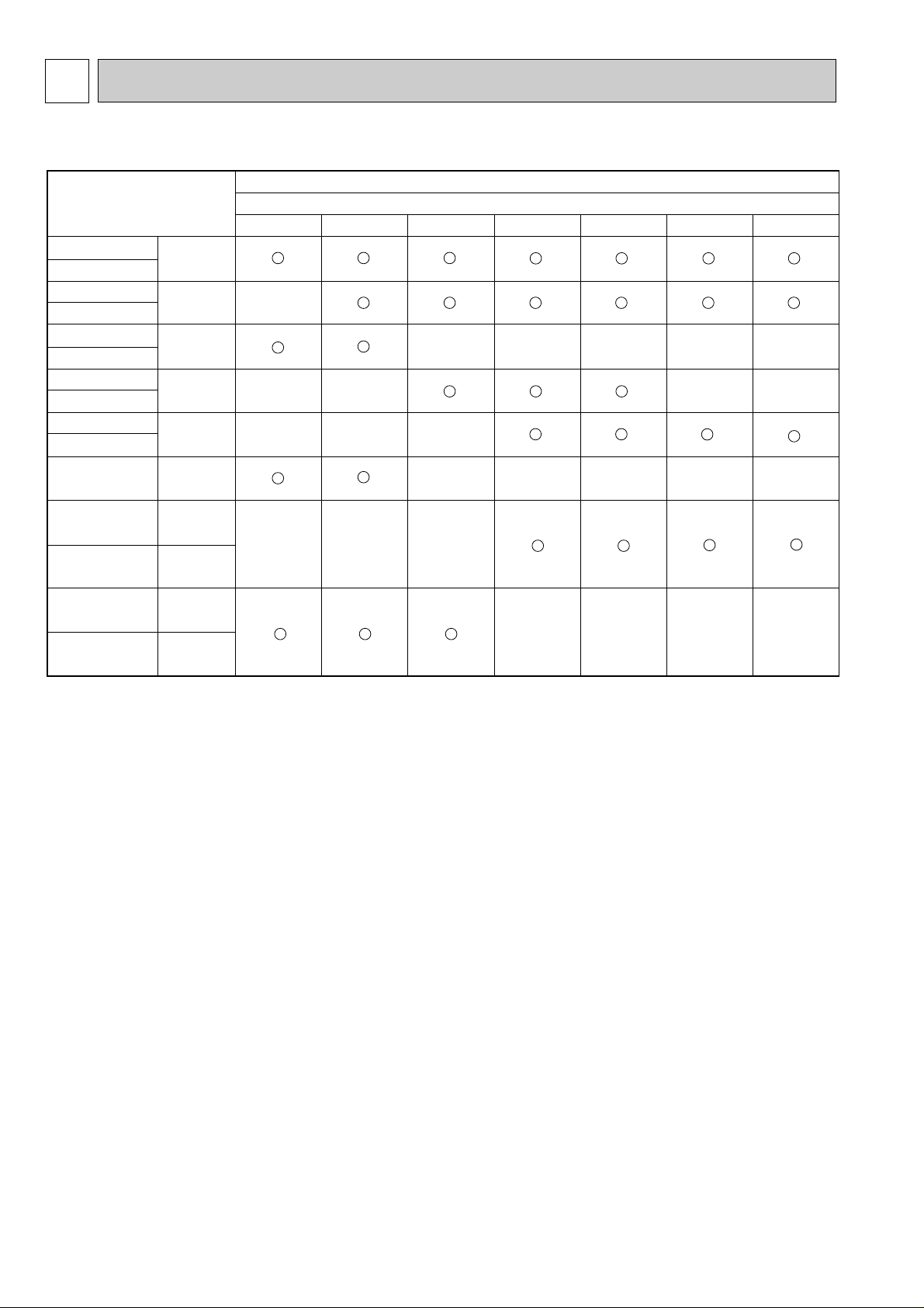
Indoor unit
Outdoor unit [PUH/PU]
OC180 Rev-A
P2GA
—
—
—
P2.5GA
—
—
—
—
P3GA
—
—
—
P4GA
—
—
—
P5GA
—
—
—
—
P6GA
—
—
—
—
PAIRING TABLE OF THE INDOOR AND OUTDOOR UNITS
2
Page 3
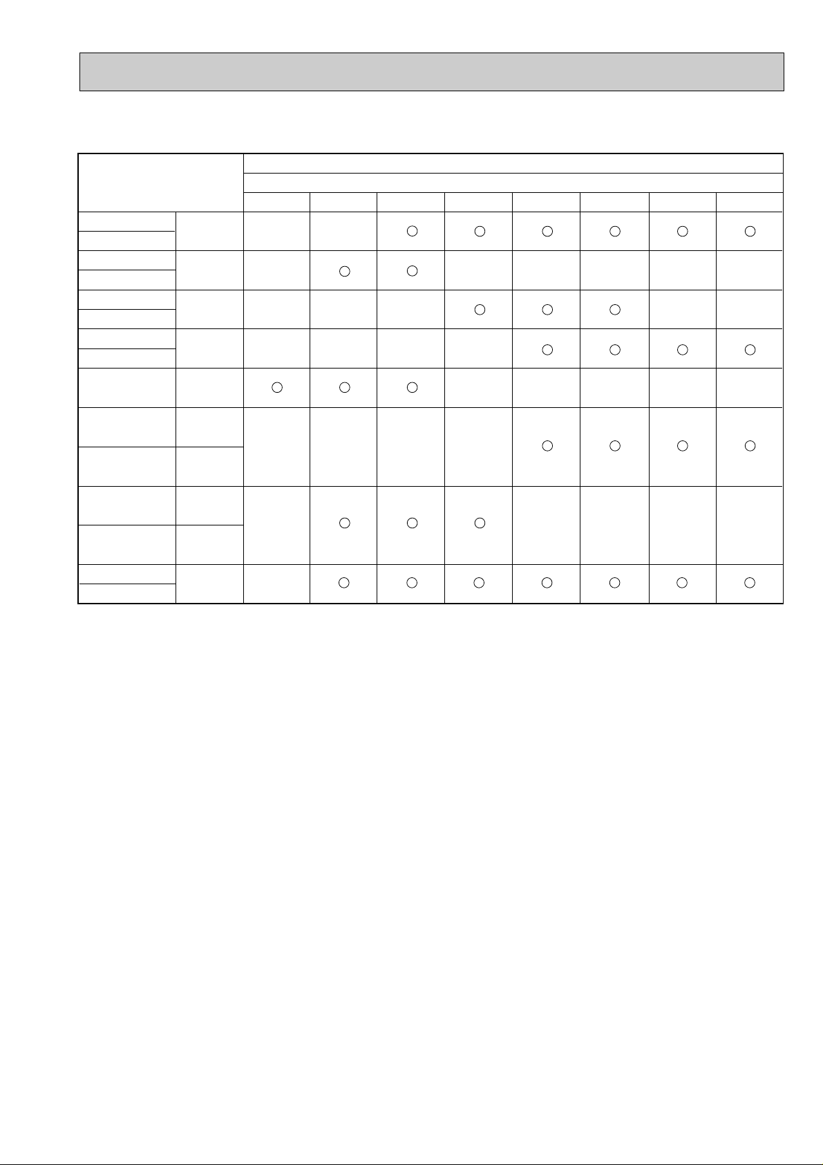
Indoor unit
Service ref.
PCH–P·GAH1
PCA–P·GA1
PKH–P·GALH1
PKA–P·GAL1
PKH–P·FALH2
PKA–P·FAL2
PSH–P·GAH1
PSA–P·GA1
PMH–P·BA1
PLH–P·AAH1.UK
PLA–P·AA1.UK
PLH–P·KAH1.UK
PLA–P·KA1.UK
PEHD–P
PEAD–P
·EAH.UK
·EA.UK
P1GAA.UK
OC182
REVISED EDITION-B
OC176
REVISED EDITION-B
OC175
REVISED EDITION-B
OC212
REVISED EDITION-A
OC238
REVISED EDITION-B
OC236
REVISED EDITION-A
OC241
REVISED EDITION-A
OC235
REVISED EDITION-A
OC240
REVISED EDITION-A
MEE01K
048
—
—
—
—
—
—
—
P1.6GAA.UK
—
—
—
—
P2GAA.UK
—
—
—
Outdoor unit [PUH/PU]
OC261
P2.5GAA.UK
—
—
—
—
P3GAA.UK
—
—
—
P4GAA.UK
—
—
—
P5GAA.UK
—
—
—
—
P6GAA.UK
—
—
—
—
3
Page 4
2
A
J J
D
E
G
L L
C
K K
B
F
I I
H
F
I
E
A
J J
D
E
G
L L
C
K K
B
F
I I
H
F
I
E
J
L
K
F
I
E
A
J J
D
E
G
L L
C
K K
B
F
I I
H
F
I
E
J
L
K
F
I
E
J
L
K
F
I
E
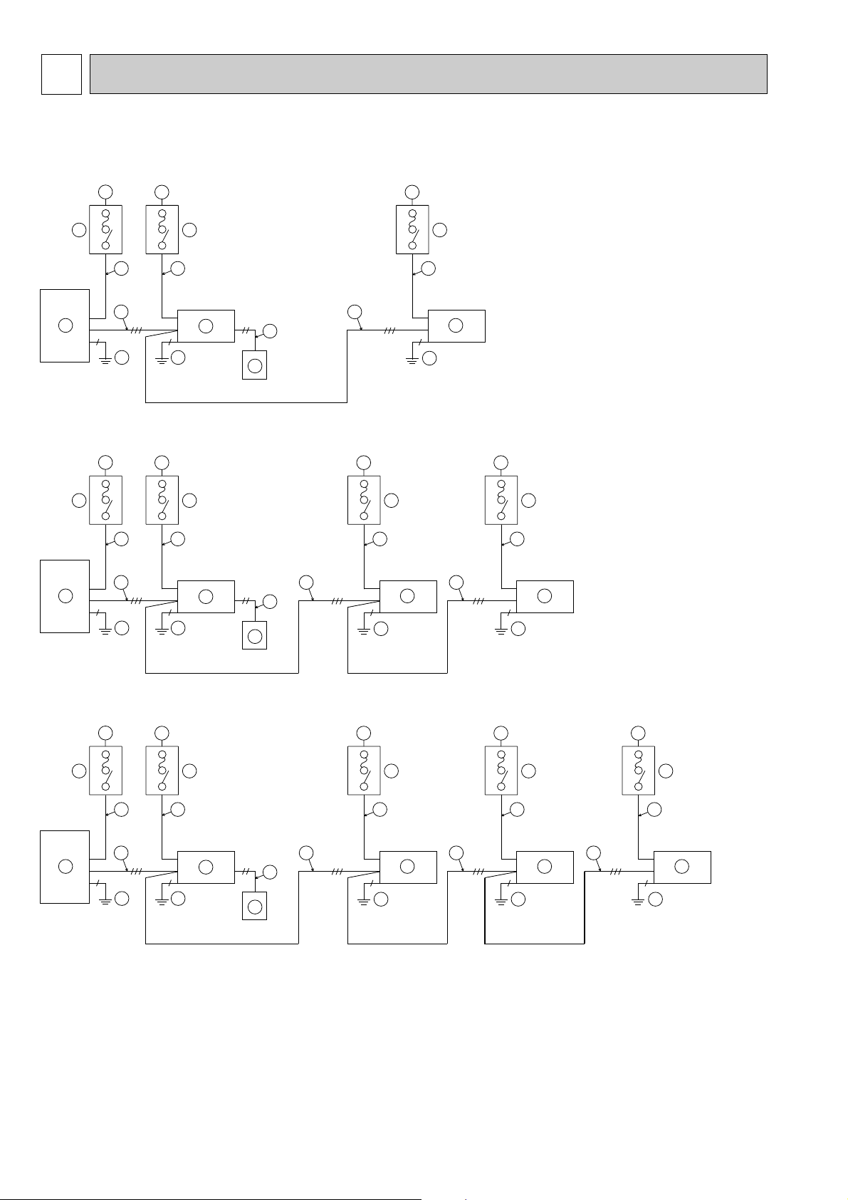
SPECIFICATIONS FOR ELECTRICAL WORK
2-1. Electrical check
1) Simultaneous twin system
2) Simultaneous triple system
A Power supply for outdoor unit
B Main switch/fuse(purchased locally)for
outdoor unit
C Power supply wiring for outdoor unit
D Outdoor unit
E Indoor unit
F Connection wiring for indoor/outdoor
units(polarity)
G Remote controller
H Connection wiring for indoor/remote
controller(no polarity)
I Grounding
J,K,L:with electric heater model only
J Power supply for electric heater
K Main switch/fuse for electric heater
L Power supply wiring for electric heater
..
Caution:
Both the indoor unit and the outdoor unit
must be grounded.
3) Simultaneous quadruple system
4
Page 5
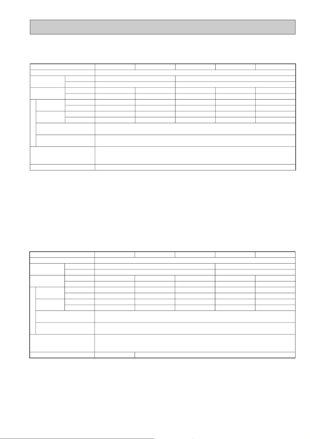
2-2. Field electrical wiring(power wiring specifications)
Heater
Power supply
Outdoor unit
Power supply
Phase
Frequency & Voltage
Indoor unit (A)
Outdoor unit (A)
Wire No.
Size (e)
Wire No.
Size (e)
16/16
32/32
3
1.5
3
4
16/16
63/63
3
1.5
3
10
16/16
25/16
3
1.5
5
2.5
16/16
32/25
3
1.5
5
2.5
16/16
32/32
3
1.5
5
4
Models (Outdoor unit)
~ / N (Single)
50Hz, 220-230-240V
Outdoor unit
Power supply
Input capacity
Main switch/Fuse
Indoor unit/Outdoor unit connecting
Wire No. o size (e)
Remote controller-indoor unit connecting
Wire No. o size (e)
indoor unit power supply
~ / N (Single), 50Hz, 220-230-240V
Control circuit rating
Heater power supply
Wiring
3N ~ (3ph)
50Hz, 380/220-400/230-415/240V
3 o 2.5 flat cable (Polar)
Cable 2C o 0.69
This wire is accessory of remote controller (Wire length: 10m,Non-polar)
Indoor unit-Outdoor unit: S1-S2 AC220V-230V-240V
S2-S3 DC24V
Remote controller-Indoor unit: DC14V
~ / N (Single phase), 50Hz, 220-230-240V
P1.6, 2, 2.5V P1.6, 2, 2.5Y P3, 4Y P5, 6YP3V
Heater
Power supply
Outdoor unit
Power supply
Phase
Frequency & Voltage
Indoor unit(A)
Outdoor unit(A)
Wire No.
Size(e)
Wire No.
Size(e)
—
25/25
—
—
3
2.5
16/16
32/32
3
1.5
3
4
16/16
63/63
3
1.5
3
10
16/16
25/25
3
1.5
5
2.5
16/16
32/32
3
1.5
5
4
Models (Outdoor unit)
~ / N (Single)
50Hz, 220-230-240V
Outdoor unit
Power supply
Input capacity
Main switch/Fuse
Indoor unit/Outdoor unit connecting
Wire No. o size (e)
Remote controller-indoor unit connecting
Wire No. o size (e)
Indoor unit power supply
~ / N (Single), 50Hz, 220-230-240V
Control circuit rating
Heater power supply
Wiring
3N ~ (3ph)
50Hz, 380/220-400/230-415/240V
3 o 2.5 cable (Polar)
Cable 2C o 0.69
This wire is accessory of remote controller (Wire length: 10m, Non-polar)
Indoor unit-Outdoor unit: S1-S2 AC220V-230V-240V
S2-S3 DC24V
Remote controller-Indoor unit: DC14V
P1V
—
~ / N (Single phase), 50Hz, 220-230-240V
P3, 4V P1.6, 2, 2.5, 3, 4Y P5, 6YP1.6, 2, 2.5V
PU(H)-P•GA, PU(H)-P•GA1
Check items
1. Grounding protection with a no-fuse breaker (earth leakage breaker[ELB]) is usually installed for B and K.
2. The power cable thickness of C and B have been selected for a voltage drop up to 20m.If the cable length exceeds
20m,select a cable thickness appropriate to that estimated voltage drop.
3. The connection wiring F between the outdoor and indoor units can be extended up to a maximum of 50 meters,and the
total extension including the crossover wiring between rooms is a maximum of 80m.
Use flat cable (three core wires) for indoor and outdoor connection wiring,and connect the core wires in their line-up order
to S1,S2,and S3 of the outdoor unit’s terminal board.(The core wire connected to terminal S2 should be in the center.)
4. Be careful about choosing the installation location for the earth leakage breaker and how it is installed as the initial electric
current may cause it to malfunction.
PU(H)-P•GAA.UK, PU(H)-P•GAA1.UK
Check items
1. The power cable thickness have been selected for a voltage drop up to 20 m. If the cable length exceeds 20 m, select a
cable thickess appropriate to tthat estimated voltage drop.
2. Be careful about choosing the installation location for the earth leakage breaker and how it is installed as the initial electric
current may cause it to maifunction.
3. Power supply cords and indoor unit / Outdoor unit connecting cords shall not be llghter than polychloroprene sheathed flexible cord. (design 254 IEC 57)
..
Caution:
Do not push the contactor button (52C) on the outdoor unit ,otherwise the compressor may be damaged.
5
Page 6
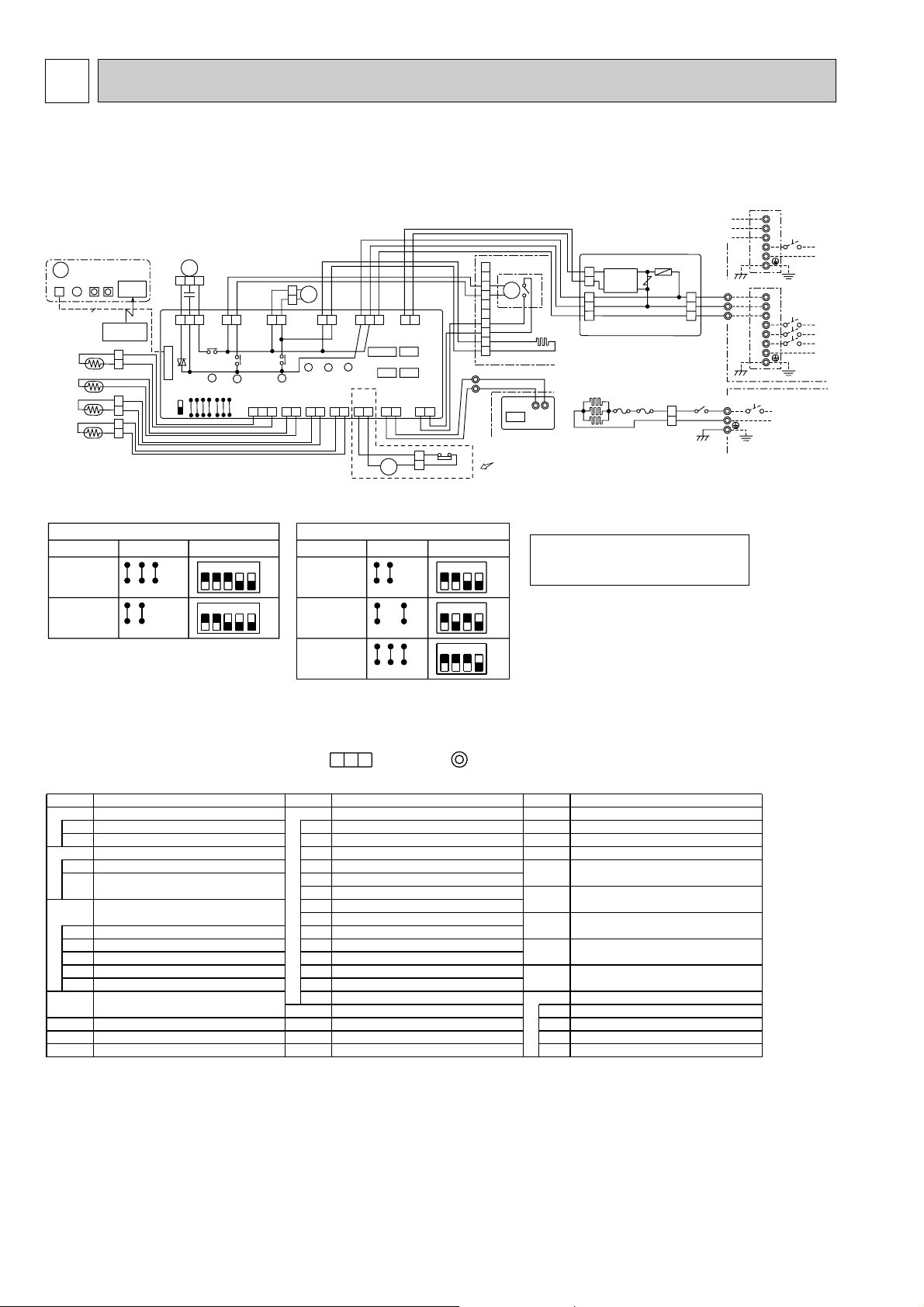
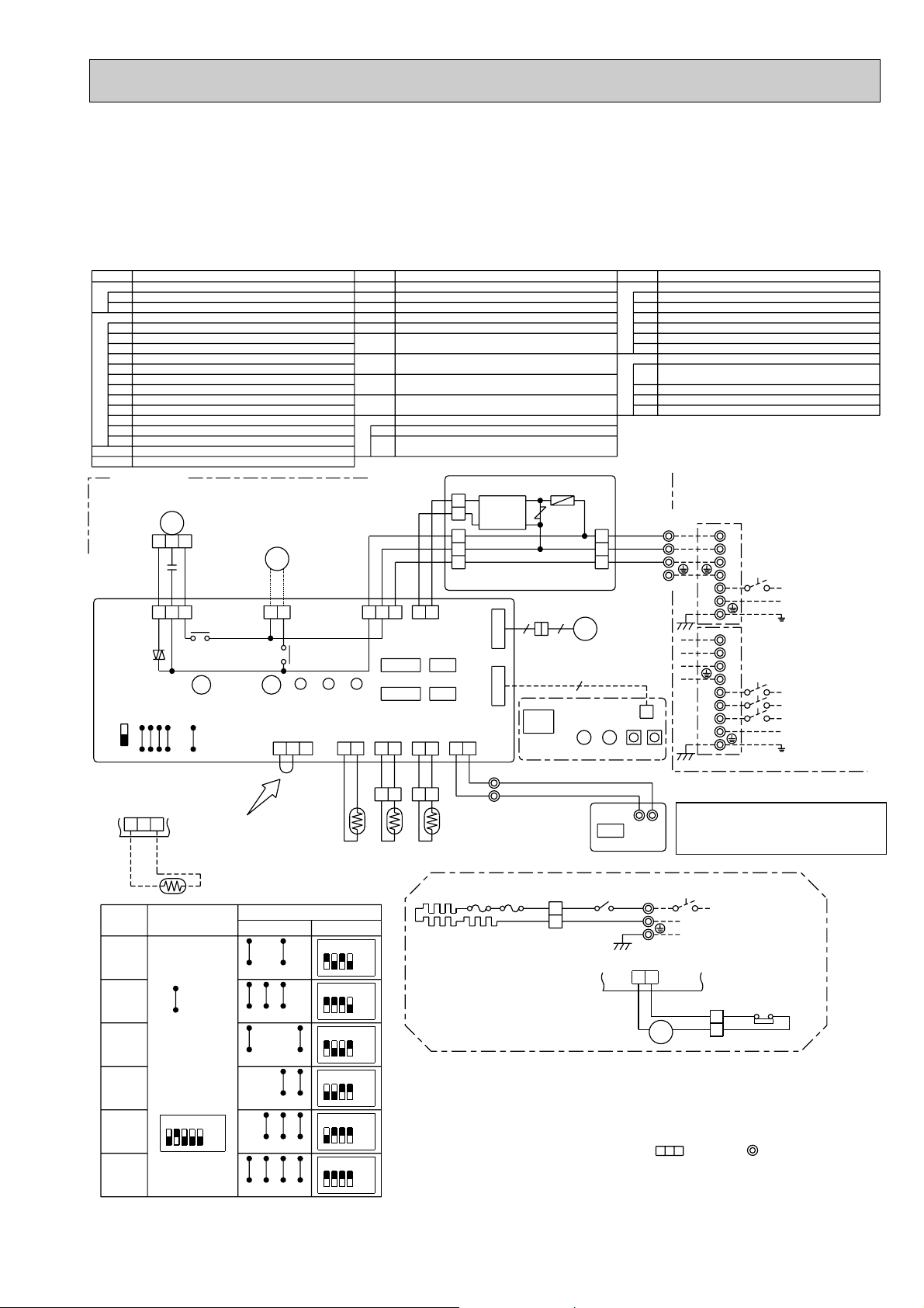
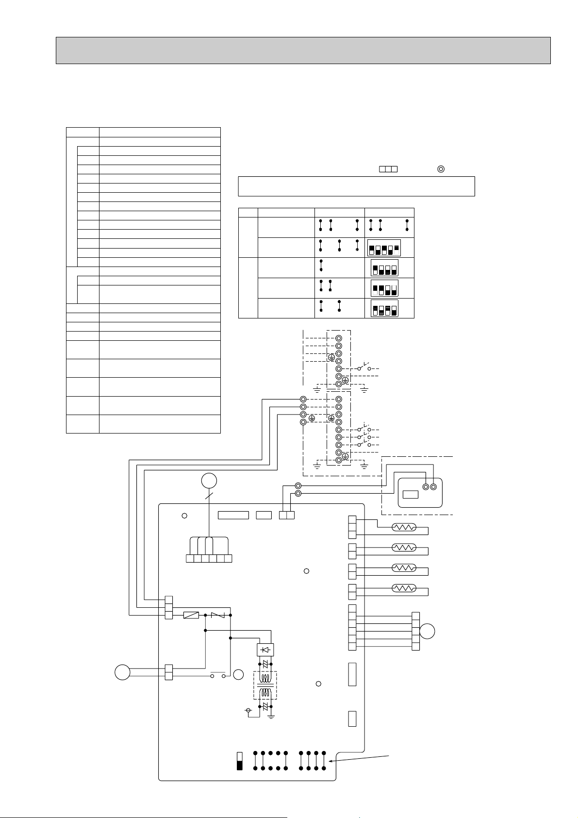
3 WIRING DIAGRAM
9
W.B
GRY
5
6
88H
26H
1
6
2
HEATER
CN24
(YLW)
1
WHT
WHT
YLW
YLW
1
2
REMOTE
CONTROLLER
CN22 (BLU)
2
1
VANE
POSITION
CN23 (GRN)
FS2
FS1
5
TB2
88H
N
L
POWER SUPPLY
~(1PHASE)
220V-240V 50Hz
BLU
RED
3
WHT
RED
RED
1
2
H1
GRN/YLW
1
2
3
CONTROLLER BOARD
CN02 (WHT)
R.B
OUTDOOR UNIT
CN01 (BLU)
3
1
2
D.U.M
CNP
(BLU)
D.SENSOR
CN31
(WHT)
X4
X3
X1
X4
REMOTE
CONTROLLER
RU
FAN
(WHT)
CN90
(WHT)
WIRELESS
W.R
CNB
SW1
SW2
LED1
BZ
J15
BLK
BLK
BLK
BLK
BLK
BLK
BRN
YLW
ORN
WHT
BLK
BRN
ORN
YLW
BLU
BLU
GRY
GRY
YLW
YLW
BLK
WHT
RED
PIPE
CN29
(BLK)
2
1
1
2
TH5
GRILLE
4
8
9
6
1
10
5
3
7
2
S1
S3
S2
TB1
L3
L1
L2
N
S1
S3
S2
TB1
L
N
X1
C
MF
3
1
2
5
3
OUTDOOR UNIT
S1
S2
S3
TB4
P.B
ZNR
2
1
F1
2
CN2
1
TB6
LS
H2
MV
DC14V
1
2
TB5
2
1
CN2S(WHT)
CN32
CN2L
1
2
POWER
CN2D (WHT)
LIQUID
CN21
(WHT)
2
1
INTAKE
CN20
(RED)
2
1
1
2
3
SW2
J22
J23
J24
VANE
CNV
(GRN)
X3
SW1
J11
J12
J13
3
1
3
1
J14
3
1
LED1
LED2
1
D.HEATER
CNC
(RED)
LED3
CN41
3
5
POWER
CN03
(RED)
DP
1
FC
I.B
SWE
ON
OFF
J21
TH2
2
DS
3
1
1
TH1
CN25
TRANSMISSION WIRES DC14V
PLH-P1.6~2.5KAH
only
PLH-P1.6~2.5KAH only
<PUH-P1.6~2.5YGA>
POWER SUPPLY
3N~(3PHASE 4WIRES)
380-415V 50Hz
<PU(H)-P1.6~2.5VGA>
POWER SUPPLY
~(1PHASE)
220-240V 50Hz
BLU
BLU
BLU
BLU
SW1
SW2
Manufacture
service board
MODELS
OFF
ON
432
J14J13J12J11
Service board
Manufacture
MODELS
15
OFF
ON
43215
J15
J14J13J12J11 J15
J23J24
1234
ON
OFF
1234
ON
OFF
J23J24
J22J21
J21J22
PLH-1.6~2.5KAH
PLH-1.6KAH
PLA-1.6KA
PLH-2KAH
PLA-2KA
PLH-2.5KAH
PLA-2.5KA
PLA-1.6~2.5KA
1234
ON
OFF
J23J24J21J22
Please set the voltage using the
remote controller. For the setting
method,please refer to the indoor
unit Installation Manual.
1.Since the outdoor side electric wiring may change be sure to check the outdoor unit electric wiring for servicing.
3.Make sure that the main power supply of the booster heater is independent.
4.Symbols used in wiring diagram above are,
2.Indoor and outdoor connecting wires are made with polarities,make wiring matching terminal numbers(S1,S2,S3).
:Connector, :Terminal block.
NOTES:
NAME
NAME
SYMBOL
INDOOR CONTROLLER BOARD
NAME
SYMBOL
INDOOR POWER BOARD
VARISTOR
FUSE (4A)
[LEGEND]
F1
REMOTE CONTROLLER BOARD
CONNECTOR (SCHEDULE TIMER)
R.B
CN2
ZNR
P.B
CONNECTOR (REMOTE SWITCH)
CONNECTOR (LOSSNAY)
CN2L
CN32
CN41
CONNECTOR (HA TERMINAL-A)
LED1
LED2
POWER SUPPLY (R.B)
LED3
TRANSMISSION (INDOOR-OUTDOOR)
JUMPER WIRE (MODEL SELECTION)
SW1
JUMPER WIRE (CAPACITY CODE)
SW2
SWITCH (EMERGENCY OPERATION)
SWE
I.B
POWER SUPPLY (I.B)
CONNECTOR (HUMIDIFIER)
CN25
FC
FAN PHASE CONTROL
X1
RELAY (DRAIN PUMP/D.HEATER)
X3
RELAY (VANE MOTOR)
X4
RELAY (FAN MOTOR)
TERMINAL BLOCK
TB6
(REMOTE CONTROLLER TRAMSMISSION LINE)
W.B
BZ
RU
BOARD (OPTION)
RECEIVING UNIT
BUZZER
SW1
LED1
SWITCH (HEATING ON/OFF)
LED (RUN INDICATOR)
SW2
SWITCH (COOLING ON/OFF)
WIRELESS REMOTE CONTROLLER
W.R
WIRELESS REMOTE CONTROLLER
(OPTION)
SYMBOL
DRAIN-UP MACHINE
DRAIN SENSOR
DEW PREVENTION HEATER
CAPACITOR (FAN MOTOR)
DP
H2
C
DS
ROOM TEMPERATURE THERMISTOR
TERMINAL BLOCK
FAN MOTOR
TERMINAL BLOCK
(REMOTE CONTROLLER TRANSMISSION LINE)
LIMIT SWITCH
VANE MOTOR
(0;/15K', 25;/5.4K' DETECT)
TERMINAL BLOCK (HEATER)
(INDOOR/OUTDOOR CONNECTING LINE)
LS
MF
TB2
MV
TB5
TB4
TH1
HEATER CONTACTOR
HEATER THERMAL SWITCH
HEATER
THERMAL FUSE (98;, 10A),(77;,10A)
CONDENSER/EVAPORATOR TEMPERATURE
THERMISTOR (0;/15K', 25;/5.4K' DETECT)
PIPE TEMPERATURE THERMISTOR/LIQUID
(0;/15K', 25;/5.4K' DETECT)
88H
26H
H1
FS1,2
HEATER
TH2
TH5
PLH-P1.6KAH, PLH-P2KAH, PLH-P2.5KAH
PLA-P1.6KA, PLA-P2KA, PLA-P2.5KA
PLA-P1.6KA1, PLA-P2KA1, PLA-P2.5KA1
6
Page 7
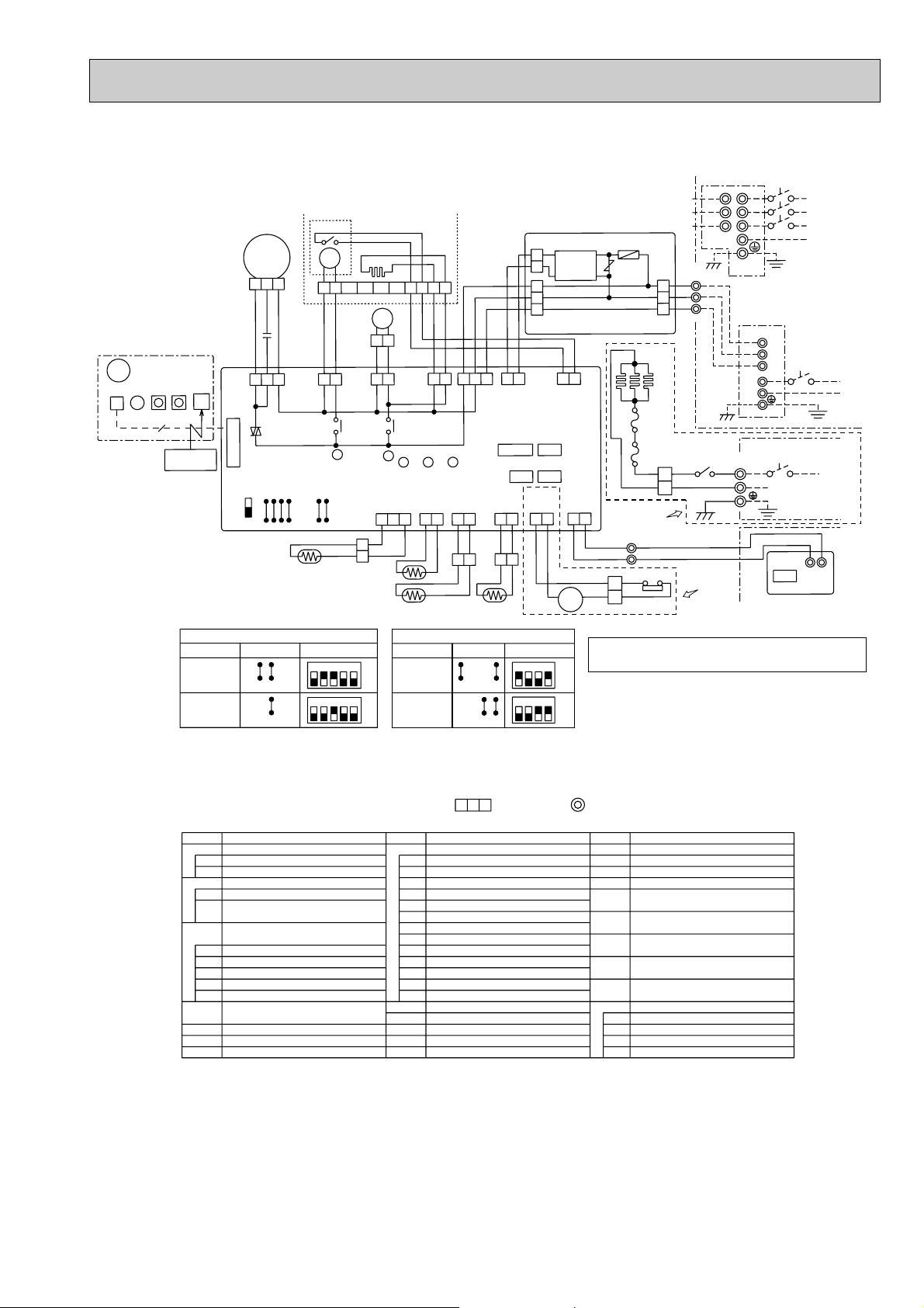
PLH-P3KAH, PLH-P4KAH
PLA-P3KA, PLA-P4KA
MF
3
12
C
BLK
WHT
W.B
CNB
BZ
RU
SW2
SW1
LED1
9
REMOTE
W.R
CONTROLLER
I.B
FAN
(WHT)
CN90
(WHT)
FC
WIRELESS
SWE
ON
OFF
1
RED
J21
35
SW2
J22
J23
J24
VANE
CNV
(GRN)
J11
J12
SW1
J13
MV
1
DS
TB1
OUTDOOR UNIT
S1
S2
YLW
1
ORN
2
BRN
3
RED
1
2
PLH-P3, 4KAH
TB4
88H
5
GRN/YLW
S3
S1
S2
S3
only
GRILLE
LS
H2
16
10
DP
2
1
GRY
GRY
3
1
D.HEATER
CNC (RED)
X1
X1
LED3
D.SENSOR
CN31
(WHT)
2
1
BLK
TH1
TH2
3
5
INTAKE
BLK
LED2
CN20
(RED)
12
1
BLU
BLU
3
LED1
LIQUID
CN21
(WHT)
BRN
ORN
YLW
513
POWER
CN03
(RED)
2
1
BLK
BLK
2
1
TH5
72
YLW
YLW
D.U.M
3
CNP
(BLU)
X3
X3
J14
J15
1
3
CONTROLLER BOARD
CN02 (WHT)
WHT
BLK
2
1
POWER
CN2D
(WHT)
CN41
CN25
HEATER
PIPE
CN24
CN29
(YLW)
(BLK)
2
1
BLK
BLK
12
CN2S(WHT)
2
DC14V
1
3
2
1
1
VANE
POSITION
CN23 (GRN)
CN2L
CN32
CONTROLLER
CN22 (BLU)
21
YLW
YLW
1
88H
WHT
BLK
2
REMOTE
2
1
BRN
BRN
6
OUTDOOR UNIT
PLH-P3, 4KAH
6
GRY
5
P.B
F1
ZNR
CN01 (BLU)
H1
FS2
FS1
RED
WHT
only
TB5
TRANSMISSION WIRES
2
DC14V
1
26H
WHT
WHT
L1
L2
L3
N
<PU(H)-P3,4YGA>
POWER SUPPLY
3N~
(3PHASE 4WIRES)
380-415V 50Hz
TB1
<PU(H)-P3VGA>
POWER SUPPLY
S1
~(1PHASE)
S2
220-240V 50Hz
S3
L
N
TB2
3
RED
L
BLU
N
POWER SUPPLY
~(1PHASE)
220V-240V 50Hz
1
TB6
R.B
2
CN2
MODELS
PLH-3, 4KAH
PLA-3, 4KA
SW1
Manufacture
J14J13J12J11
J15
J14J13J12J11 J15
Service board
432
15
ON
OFF
43215
ON
OFF
MODELS
PLH-3KAH
PLA-3KA
PLH-4KAH
PLA-4KA
SW2
Manufacture
J23J24
J22J21
J23J24
J21J22
service board
1234
ON
OFF
1234
ON
OFF
Please set the voltage using the remote controller.
For the setting method,please refer to the indoor
unit Installation Manual.
NOTES:
1.Since the outdoor side electric wiring may change be sure to check the outdoor unit electric wiring for servicing.
2.Indoor and outdoor connecting wires are made with polarities,make wiring matching terminal numbers(S1,S2,S3).
3.Make sure that the main power supply of the booster heater is independent.
4.Symbols used in wiring diagram above are,
[LEGEND]
SYMBOL
P.B
INDOOR POWER BOARD
F1
FUSE (4A)
ZNR
VARISTOR
R.B
REMOTE CONTROLLER BOARD
CN2
CONNECTOR (SCHEDULE TIMER)
TB6
TERMINAL BLOCK
(REMOTE CONTROLLER TRAMSMISSION LINE)
W.B
WIRELESS REMOTE CONTROLLER
BOARD (OPTION)
RU
RECEIVING UNIT
BZ
BUZZER
LED1
LED (RUN INDICATOR)
SW1
SWITCH (HEATING ON/OFF)
SW2
SWITCH (COOLING ON/OFF)
W.R
WIRELESS REMOTE CONTROLLER
(OPTION)
NAME
SYMBOL
INDOOR CONTROLLER BOARD
I.B
CONNECTOR (LOSSNAY)
CN2L
CONNECTOR (HUMIDIFIER)
CN25
CONNECTOR (REMOTE SWITCH)
CN32
CONNECTOR (HA TERMINAL-A)
CN41
FAN PHASE CONTROL
FC
POWER SUPPLY (I.B)
LED1
POWER SUPPLY (R.B)
LED2
TRANSMISSION (INDOOR-OUTDOOR)
LED3
JUMPER WIRE (MODEL SELECTION)
SW1
JUMPER WIRE (CAPACITY CODE)
SW2
SWITCH (EMERGENCY OPERATION)
SWE
RELAY (DRAIN PUMP/D.HEATER)
X1
RELAY (VANE MOTOR)
X3
CAPACITOR (FAN MOTOR)
C
DRAIN-UP MACHINE
DP
DRAIN SENSOR
DS
DEW PREVENTION HEATER
H2
:Connector, :Terminal (block).
NAME
SYMBOL
LIMIT SWITCH
LS
FAN MOTOR
MF
VANE MOTOR
MV
TERMINAL BLOCK (HEATER)
TB2
TERMINAL BLOCK
TB4
(INDOOR/OUTDOOR CONNECTING LINE)
TERMINAL BLOCK
TB5
(REMOTE CONTROLLER TRANSMISSION LINE)
ROOM TEMPERATURE THERMISTOR
TH1
(0;/15K', 25;/5.4K' DETECT)
PIPE TEMPERATURE THERMISTOR/LIQUID
TH2
(0;/15K', 25;/5.4K' DETECT)
TH5
CONDENSER/EVAPORATOR TEMPERATURE
THERMISTOR (0;/15K', 25;/5.4K' DETECT)
HEATER
THERMAL FUSE (77;,15A)
FS1,2
HEATER
H1
HEATER THERMAL SWITCH
26H
HEATER CONTACTOR
88H
NAME
7
Page 8
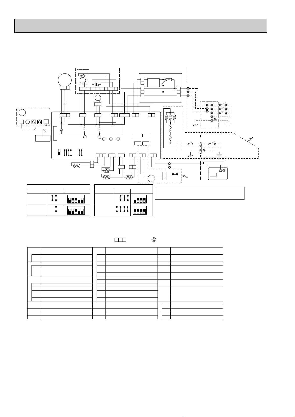
PLH-P5KAH, PLH-P6KAH
PLA-P5KA, PLA-P6KA
W.B
BZ
CNB
SW2
SW1LED1
9
REMOTE
W.R
CONTROLLER
MODELS
PLH-5, 6KAH
PLA-5, 6KA
I.B
FAN
(WHT)
RU
CN90
(WHT)
WIRELESS
SWE
ON
OFF
SW1
Manufacture
1
FC
J14J13J12J11
J15
J14J13J12J11 J15
MF
C
RED
J21
21
SW2
J22
WHT
3
J23
Service board
LS
MV
YLW
YLW
BLK
VANE
CNV
(GRN)
J24
15
31
X3
SW1
J11
J15
J12
J13
J14
DS
432
43215
OFF
OFF
D.U.M
CNP
(BLU)
X3
ON
ON
GRILLE
H2
10
527
DP
21
GRY
GRY
3531
D.HEATER
CNC (RED)
X1
X1
D.SENSOR
CN31
(WHT)
3
BLK
BLK
1
3
TH1
TH2
MODELS
PLH-5KAH
PLA-5KA
PLH-6KAH
PLA-6KA
6
1
BLU
313151
LED1LED2LED3
INTAKE
CN20
(RED)
Manufacture
J21J22
BLU
LIQUID
CN21
(WHT)
12
BLK
12
SW2
J22J21
YLW
BLK
TH5
J23J24
J23J24
BRN
ORN
POWER
CN03
(RED)
CN2S(WHT)
2
1
3
2
1
CONTROLLER BOARD
CN02 (WHT)
WHT
BLK
2
POWER
CN2D
(WHT)
CN2LCN41
CN32
CN25
PIPE
HEATER
CN29
CN24
(BLK)
(YLW)
12
2121
BLK
BLK
YLW
21
service board
1234
1234
DC14V
WHT
BLK
2
1
VANE
POSITION
CN23 (GRN)
REMOTE
CONTROLLER
CN22 (BLU)
1212
YLW
BRN
BRN
61
88H
Please set the voltage using the remote controller.
For the setting method,please refer to the indoor
unit Installation Manual.
ON
OFF
ON
OFF
F1
ZNR
OUTDOOR UNIT
CN01 (BLU)
FS2
FS1
RED
WHT
TB5
2
TRANSMISSION WIRES
1
26H
WHT
6
WHTGRY
5
P.B
YLW
1
ORN
2
BRN
3
H1
RED
1
2
PLH-P5, 6KAH
TB4
88H
5
only
S1
S2
S3
3
RED
GRN/YLW
DC14V
BLU
TB2
TB1
L1
S1
S2
L2
S3
L3
N
L
N
CN2
NOTES:
1.Since the outdoor side electric wiring may change be sure to check the outdoor unit electric wiring for servicing.
2.Indoor and outdoor connecting wires are made with polarities,make wiring matching terminal numbers(S1,S2,S3).
3.Make sure that the main power supply of the booster heater is independent.
4.Symbols used in wiring diagram above are,
[LEGEND]
SYMBOL
P.B
INDOOR POWER BOARD
F1
FUSE (4A)
ZNR
VARISTOR
R.B
REMOTE CONTROLLER BOARD
CN2
CONNECTOR (SCHEDULE TIMER)
TB6
TERMINAL BLOCK
(REMOTE CONTROLLER TRAMSMISSION LINE)
W.B
WIRELESS REMOTE CONTROLLER
BOARD (OPTION)
RU
RECEIVING UNIT
BZ
BUZZER
LED1
LED (RUN INDICATOR)
SW1
SWITCH (HEATING ON/OFF)
SW2
SWITCH (COOLING ON/OFF)
W.R
WIRELESS REMOTE CONTROLLER
(OPTION)
NAME
SYMBOL
INDOOR CONTROLLER BOARD
I.B
CONNECTOR (LOSSNAY)
CN2L
CONNECTOR (HUMIDIFIER)
CN25
CONNECTOR (REMOTE SWITCH)
CN32
CONNECTOR (HA TERMINAL-A)
CN41
FAN PHASE CONTROL
FC
POWER SUPPLY (I.B)
LED1
POWER SUPPLY (R.B)
LED2
TRANSMISSION (INDOOR-OUTDOOR)
LED3
JUMPER WIRE (MODEL SELECTION)
SW1
JUMPER WIRE (CAPACITY CODE)
SW2
SWITCH (EMERGENCY OPERATION)
SWE
RELAY (DRAIN PUMP/D.HEATER)
X1
RELAY (VANE MOTOR)
X3
CAPACITOR (FAN MOTOR)
C
DRAIN-UP MACHINE
DP
DRAIN SENSOR
DS
DEW PREVENTION HEATER
H2
:Connector, :Terminal (block).
NAME
SYMBOL
LIMIT SWITCH
LS
FAN MOTOR
MF
VANE MOTOR
MV
TERMINAL BLOCK (HEATER)
TB2
TERMINAL BLOCK
TB4
(INDOOR/OUTDOOR CONNECTING LINE)
TERMINAL BLOCK
TB5
(REMOTE CONTROLLER TRANSMISSION LINE)
ROOM TEMPERATURE THERMISTOR
TH1
(0;/15K', 25;/5.4K' DETECT)
PIPE TEMPERATURE THERMISTOR/LIQUID
TH2
(0;/15K', 25;/5.4K' DETECT)
TH5
CONDENSER/EVAPORATOR TEMPERATURE
THERMISTOR (0;/15K', 25;/5.4K' DETECT)
HEATER
THERMAL FUSE (77;,15A)
FS1,2
HEATER
H1
HEATER THERMAL SWITCH
26H
HEATER CONTACTOR
88H
NAME
OUTDOOR UNIT
<PU(H)-P5, 6YGA>
POWER SUPPLY
3N~
(3PHASE 4WIRES)
380-415V 50Hz
POWER SUPPLY
~(1PHASE)
220V-240V 50Hz
R.B
12
TB6
PLH-P5, 6KAH
only
8
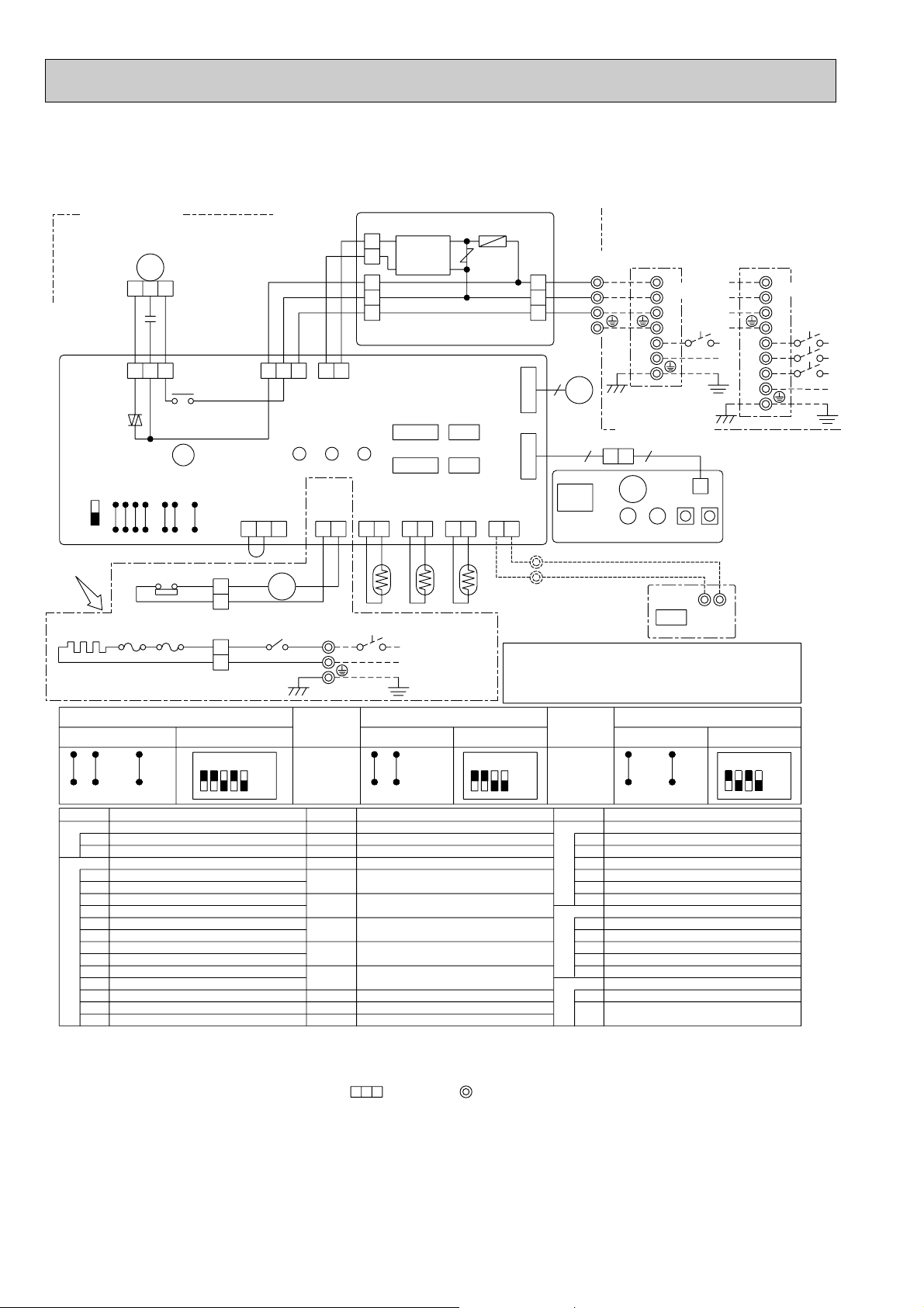
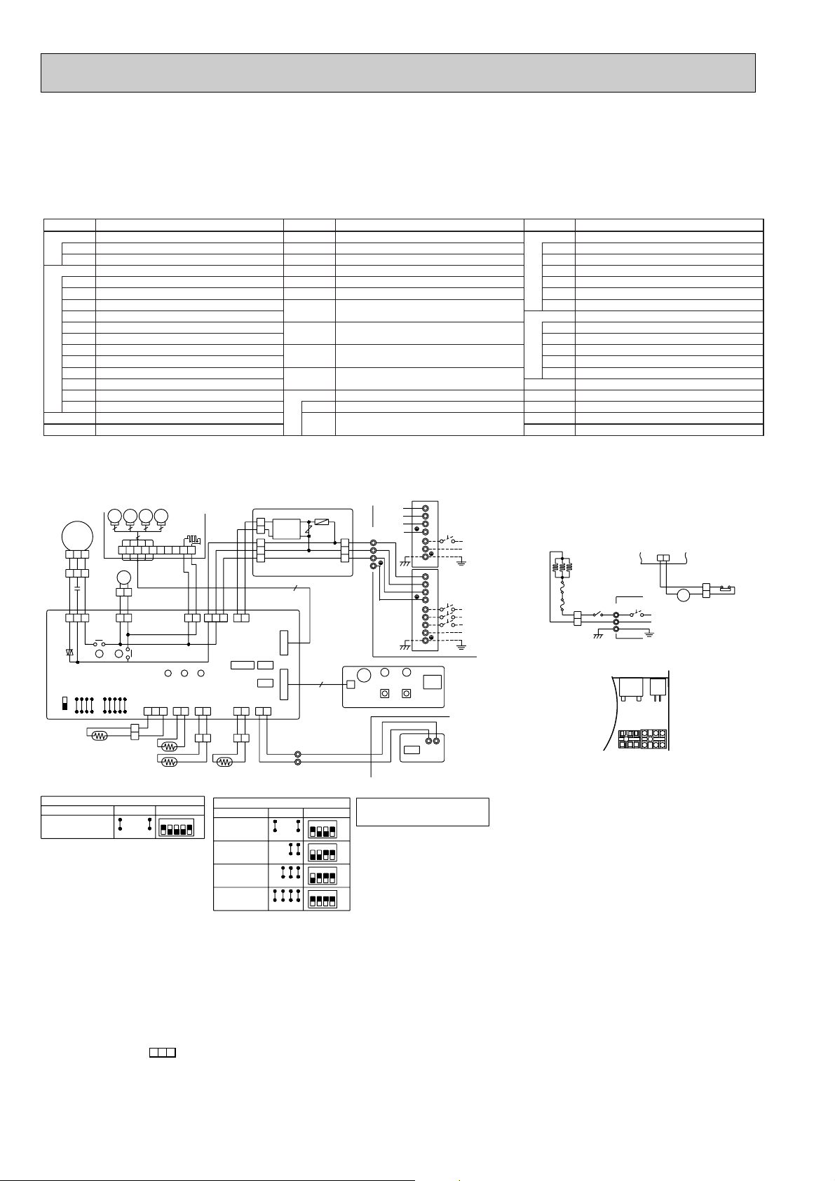
Page 9
PCH-P2GAH, PCH-P2.5GAH, PCH-P3GAH, PCH-P4GAH, PCH-P5GAH, PCH-P6GAH
PCH-P2GAH1, PCH-P2.5GAH1, PCH-P3GAH1, PCH-P4GAH1,PCH-P5GAH1, PCH-P6GAH1
PCA-P2GA, PCA-P2.5GA, PCA-P3GA, PCA-P4GA, PCA-P5GA, PCA-P6GA
PCA-P2GA
1, PCA-P2.5GA1, PCA-P3GA1, PCA-P4GA1, PCA-P5GA1, PCA-P6GA1
INDOOR POWER BOARD
P.B
FUSE(4A)
F1
VARISTOR
ZNR
INDOOR CONTROLLER BOARD
I.B
CONNECTOR(LOSSNAY)
CN2L
CONNECTOR(REMOTE SWITCH)
CN32
CONNECTOR(HA TERMINAL-A)
CN41
JUMPER WIRE(MODEL SELECTION)
SW1
JUMPER WIRE(CAPACITY CODE)
SW2
SWITCH(EMERGENCY OPERATION)
SWE
RELAY(DRAIN PUMP)
X1
RELAY(FAN MOTOR)
X4
FAN PHASE CONTROL
FC
POWER SUPPLY(I.B)
LED1
POWER SUPPLY(R.B)
LED2
TRANSMISSION(INDOOR-OUTDOOR)LED3
CAPACITOR(FAN MOTOR)C
FAN MOTORMF
INDOOR UNIT
MF
123
C
I.B
FAN
(WHT)
RED
1
FC
SWE SW1SW2
ON
J21
J22
J23
OFF
When installing drain-up
machine(Optional part).
J24
CN31 DRAIN SENSOR
(WHT)
312
DS
MODELS
P2
<For manufacture>
P2.5
P3
P4
<For service board>
P5
P6
(OPTION)
DP
WHT
BLK
D.U.M
35
CNP
(BLU)
X4
X4
J14
J13
J12
J11
J15
wWhen installing optional
drain-up machine,disconnect
the CN31 jumper connector
and replace it with the
drain sensor(DS).
SW1
J15J14J13J12J11
54321
ON
OFF
1
X1
X1
D.SENSOR
CN31
(WHT)
Manufacture
J22J23
J21
J22
J23
J21
J22
J23
J21
J22
J23
J21
J22
J23
J21
J21
J22
J23
3
LED3 LED2 LED1
J24
J24
J24
J24
J24
J24
POWER
321
SW2
Service board
1
1
1
1
1
VANE MOTORMV
DRAIN-UP MACHINE(OPTION)
DP
DRAIN SENSOR(OPTION)DS
TB2
TERMINAL BLOCK(HEATER)
TERMINAL BLOCK(INDOOR/OUTDOOR CONNECTING LINE)
TB4
TERMINAL BLOCK(REMOTE CONTROLLERTB5
TRANSMISSION LINE)
TH1 ROOM TEMPERATURE THERMISTOR
(0;/15k' ,25;/5.4k' DETECT)
PIPE TEMPERATURE THERMISTOR/LIQUID
TH2
(0;/15k', 25;/5.4k' DETECT)
TH5
CONDENSER/ EVAPORA T OR TEMPERATURE THERMISTOR
(0;/15k', 25;/5.4k' DETECT)
R.B
REMOTE CONTROLLER BOARD
CONNECTOR(PROGRAM TIMER)
CN2
TERMINAL BLOCK(REMOTE CONTROLLER
TB6
TRANSMISSION LINE)
CN2S(WHT)
2
1
3
2
1
CONT.BOARD
YLW
13 21
CN03
(RED)
INTAKE
CN20
(RED)
12 12
TH1
BRN
ORN
BLK
5
POWER
CN2D(WHT)
CN41 CN2L
CN25 CN32
LIQUID
PIPE
CN21
CN29
(WHT)
(BLK)
BLK
BLK
BLK
12
TH2 TH5
WHT
REMOCON
CN22
(BLU)
21
BLK
21
CN02(WHT)
VANE
CN6V
(WHT)
WIRELESS
CN90
(WHT)
21
BLU
BLU
H1
234
ON
OFF
234
234
234
234
ON
OFF
ON
OFF
ON
OFF
ON
OFF
4321
ON
OFF
PCH-P2~P6GAH only
NOTES:
1.Since the outdoor side electric wiring may change be sure to check the outdoor unit
electric wiring for servicing.
2.Indoor and outdoor connecting wires are made with polarities,make wiring matching
terminal numbers(S1,S2,S3).
3.Make sure that the main power supply of the booster heater is independent.
4.Symbols used in wiring diagram above are, :Connector, :Terminal block.
NAME SYMBOLNAME SYMBOLSYMBOL
F1
DC14V
ZNR
1
2
3
6
MV
9
6
OUTDOOR
CN01(BLU)
BZ
RU
RECEIVER
LED2
LED1 SW1SW2
2
1
TRANSMISSION WIRES DC14V
RED
WHT
1
2
R.B
RED
CN2
88H
53
TB5
FS2FS1
GRN/YLW
I.B
W.B
WIRELESS REMOTE CONTROLLER BOARD(OPTION)
RU
RECEIVING UNIT
BZ
BUZZER
LED1
LED(RUN INDICATOR)
LED2
LED(HOT ADJUST)
SW1
SWITCH(HEATING ON/OFF)
SWITCH(COOLING ON/OFF)SW2
HEATER
FS1,2
THERMAL FUSE<98;10A:2GAH / 117;16A:4GAH
110;16A:2.5,3GAH,5,6GAH>
H1
HEATER
HEATER THERMAL SWITCH
26H
HEATER CONTACTOR
88H
NAME
P.B
OUTDOOR UNIT
TB4
YLW
ORN
BRN
S1
S2
S1
S2
S3S3
<PU(H)-P2~3VGA(A)>
TB1
L
N
S1
S2
<PU(H)-P2~6YGA(A)>
TB1
S3
L1
CNB
L2
L3
N
W.B
Please set the voltage using the remote
controller.
21
For the setting method, please refer to
TB6
the indoor unit installation manual.
TB2
L
RED
BLU
N
POWER SUPPLY
~(1PHASE)
220-240V 50HZ
HEATER
CN24
(YLW)
21
YLW
YLW
16
GRY
88H
26H
RED
6
RED
5
POWER SUPPLY
~(1PHASE)
220-240V 50Hz
POWER SUPPLY
3N~(3PHASE 4WIRES)
380-415V 50Hz
9
Page 10
PKH-P1.6GALH, PKH-P2GALH, PKH-P1.6GALH1, PKH-P2GALH1
9
Please set the voltage using the
remote controller.
For the setting method,please refer to
the indoor unit Installation Manual.
9
ZNR
VANE
CN6V
(WHT)
R.B
F1
OUTDOOR
CN01(BLU)
P.B
3
2
1
CONT.BOARD
CN02(WHT)
CN2S(WHT)
DC14V
CN2
TB6
21
1
TB5
2
MV
FAN
(WHT)
LED3 LED2 LED1
INDOOR UNIT
12 12
J14
J13
J12
J11
OFF
ON
SWE SW1SW2
21
D.SENSOR
CN31
(WHT)
INTAKE
CN20
(RED)
LIQUID
CN21
(WHT)
REMOCON
CN22
(BLU)
POWER
CN2D(WHT)
POWER
CN03
(RED)
123
1
2
3
2
1
1
I.B
TH1
5
MF
C
35
FC
13 21
321
CN41 CN2L
X4
J15
X4
TH2 TH5
PIPE
CN29
(BLK)
21
WIRELESS
CN90
(WHT)
RED
YLW
CN25 CN32
BRN
ORN
BRN
ORN
YLW
WHT
BLK
WHT
BLK
6
TRANSMISSION WIRES DC14V
S1
S2
S3
OUTDOOR UNIT
TB1
L
N
PE
TB4
S1
S2
S3
RECEIVER
RU
CNB
LED2
BZ
LED1 SW1SW2
W.B
J21
J22
J23
J24
<PU(H)-P1.6, 2VGA(A)>
POWER SUPPLY
~(1PHASE)
220-240V 50Hz
S1
S2
S3
TB1
L3
L2
L1
N
PE
<PU(H)-P1.6, 2YGA(A)>
POWER SUPPLY
3N~(3PHASE 4WIRES)
380-415V 50Hz
FS2FS1
WHT
RED
3
1
RED
53
88H
TB2
BLU
RED
GRN/YLW
L
N
PE
POWER SUPPLY
~(1PHASE)
220-240V 50Hz
H1
21
HEATER
CN24
(YLW)
BRN
YLW
16
88H
GRY
6
5
26H
PKH-P1.6, 2GALH
only
WHT
WHT
TERMINAL BLOCK(INDOOR/OUTDOOR
SW2
Manufacture Service board
J24J23J22J21
OFF
1ON432
MODEL
P2
SW2
J24J23J22J21
Manufacture
OFF
1ON432
Service board
MODEL
P1.6
SW1
Manufacture Service board
J15J14J13J12J11
OFF
ON
54321
BUZZER
BZ
RU
RECEIVING UNIT
WIRELESS REMOTE CONTROLLER BOARD
W.B
REMOTE CONTROLLER BOARD(OPTION)
R.B
CN2
TB6
CONNECTOR(PROGRAM TIMER)
TRANSMISSION LINE)
TERMINAL BLOCK(REMOTE CONTROLLER
THERMAL FUSE<84;10A>
FS2
TRANSMISSION(INDOOR-OUTDOOR)
LED3
VANE MOTOR
MV
POWER SUPPLY(R.B)
POWER SUPPLY(I.B)
LED2
LED1
SWITCH(COOLING ON/OFF)
SW2
SW1
LED2
LED1
LED(RUN INDICATOR)
SWITCH(HEATING ON/OFF)
LED(HOT ADJUST)
THERMAL FUSE<104;10A>
HEATER CONTACTOR
HEATER THERMAL SWITCH
HEATER
88H
26H
FS1
CONDENSER /EVAPORATOR TEMPERATURE
THERMISTOR (0;/15k',25;/5.4k' DETECT)
NAME
HEATER
TRANSMISSION LINE)(OPTION)
TERMINAL BLOCK(REMOTE CONTROLLER
TB5
F1
ZNR
P.B
PIPE TEMPERATURE THERMISTOR/LIQUID
TH5
TH2
TH1
ROOM TEMPERATURE THERMISTOR
(0;/15k',25;/5.4k' DETECT)
(0;/15k',25;/5.4k' DETECT)
TERMINAL BLOCK(HEATER)
CONNECTING LINE)
TB4
TB2
FAN MOTOR
MF
CAPACITOR(FAN MOTOR)
C
FAN PHASE CONTROL
RELAY(FAN MOTOR)
SWITCH(EMERGENCY OPERATION)
JUMPER WIRE(CAPACITY CODE)
JUMPER WIRE(MODEL SELECTION)
CONNECTOR(HA TERMINAL-A)
CONNECTOR(REMOTE SWITCH)
CONNECTOR(LOSSNAY)
FC
X4
SWE
SW2
SW1
CN41
CN32
CN2L
INDOOR CONTROLLER BOARD
VARISTOR
FUSE(4A)
INDOOR POWER BOARD
I.B
NAME SYMBOLNAME SYMBOLSYMBOL
H1
NOTES:
:Connector, :Terminal (block).
2.Indoor and outdoor connecting wires are made with polarities,make wiring matching terminal numbers(S1,S2,S3).
4.Symbols used in wiring diagram above are,
3.Make sure that the main power supply of the booster heater is independent.
1.Since the outdoor side electric wiring may change be sure to check the outdoor unit electric wiring for servicing.
PKA-P1.6GAL, PKA-P2GAL, PKA-P1.6GAL1, PKA-P2GAL1
10
Page 11
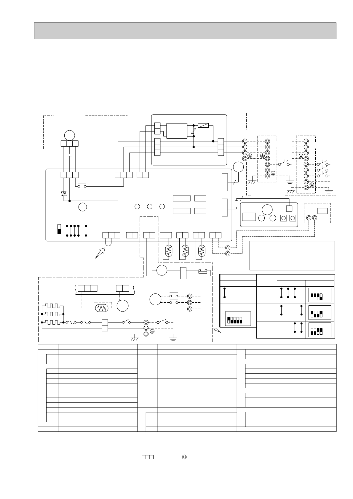
PKH-P2.5FALH, PKH-P3FALH, PKH-P4FALH
PKH-P2.5FALH1, PKH-P3FALH1, PKH-P4FALH1
PKH-P2.5FALH2, PKH-P3FALH2, PKH-P4FALH2
PKA-P2.5FAL, PKA-P3FAL, PKA-P4FAL
PKA-P2.5FAL1, PKA-P3FAL1, PKA-P4FAL1
PKA-P2.5FAL2, PKA-P3FAL2, PKA-P4FAL2
<PU(H)-P2.5,3VGA(A)>
INDOOR UNIT
CN2S(WHT)
2
DC14V
WHT
BLK
1231
HEATER
CN24
(YLW)
12
YLW
BRN
(OPTION)
TB2
L
N
PE
MV
TB2
TB4
TB5
TH1
TH2
TH5
W.B
RU
BZ
LED1
LED2
1
3
2
1
CONT.BOARD
CN02(WHT)
CN2LCN41
CN32CN25
LED1LED2LED3
PIPE
LIQUID
INTAKE
CN20
(RED)
CN21
(WHT)
2121
CN29
(BLK)
12
TH1
61
GRY
WHT
88H
5
6
WHT
TB4
S1
DP
XP
S2
S3
POWER SUPPLY
~(1PHASE)
220-240V 50Hz
VANE MOTOR
TERMINAL BLOCK(HEATER)
TERMINAL BLOCK(INDOOR/OUTDOOR
CONNECTING LINE)
TERMINAL BLOCK(REMOTE CONTROLLER
TRANSMISSION LINE)(OPTION)
ROOM TEMPERATURE THERMISTOR
(0;/15k',25;/5.4k' DETECT)
PIPE TEMPERATURE THERMISTOR/LIQUID
(0;/15k',25;/5.4k' DETECT)
CONDENSER / EVAPORATOR TEMPERATURE THERMISTOR
(0;/15k',25;/5.4k' DETECT)
WIRELESS REMOTE CONTROLLER BOARD
RECEIVING UNIT
BUZZER
LED(RUN INDICATOR)
LED(HOT ADJUST)
MF
123
C
I.B
FAN
(WHT)
FC
RED
1
WHT
BLK
53
X4
POWER
CN03
(RED)
YLW
BRN
ORN
5
POWER
CN2D(WHT)
X4
PUMP
CN27
(RED)
21
ON
OFF
J21
J12
J13
J14
D.SENSOR
CN31
(WHT)
J15
123
SW2 SW1SWE
J24
J23
J22
J11
wWhen installing optional
drain-up machine,
disconnect the CN31
jumper connector and
replace it with the
drain sensor(DS).
CN31 DRAIN SENSOR
(WHT)
When installing
drain-up machine
(Optional part).
CN27 PUMP
(RED)
213
21
H1
FS1 FS2
DS
RED
WHT
XP
88H
RED
1
2
35
RED
BLU
GRN/YLW
SYMBOL SYMBOLNAME SYMBOLNAME
P.B
I.B
C
MF
INDOOR POWER BOARD
FUSE(4A)
F1
VARISTOR
ZNR
INDOOR CONTROLLER BOARD
CN2L
CONNECTOR(LOSSNAY)
CN32
CONNECTOR(REMOTE SWITCH)
CN41
CONNECTOR(HA TERMINAL-A)
SW1
JUMPER WIRE(MODEL SELECTION)
SW2
JUMPER WIRE(CAPACITY CODE)
SWE
SWITCH(EMERGENCY OPERATION)
X4
RELAY(FAN MOTOR)
FC
FAN PHASE CONTROL
LED1
POWER SUPPLY(I.B)
LED2
POWER SUPPLY(R.B)
LED3
TRANSMISSION(INDOOR-OUTDOOR)
CAPACITOR(FAN MOTOR)
FAN MOTOR
F1
ZNR
OUTDOOR
CN01(BLU)
VANE
CN6V
(WHT)
WIRELESS
CN90
(WHT)
REMOCON
CN22
(BLU)
12
TH5TH2
26H
P.B
YLW
1
ORN
2
BRN
3
2
1
TB5
Manufacture
J11J12J13J14J15
Service board
12345
PKH-P2.5~4FALH
PKH-P2.5~4FALH
only
<PU(H)-P2.5,3,4VGAA.UK>
POWER SUPPLY
~(1PHASE)
220-240V 50Hz
TB4
MV
6
9
SW1
HEATER
R.B
DRAIN-UP MACHINE(OPTION)
S1
S1
S2
S2
S3
TB1
S3
L
N
PE
OUTDOOR UNIT
RECEI
-VER
RU
TRANSMISSION WIRES DC14V
Please set the voltage
using the remote controller.
For the setting method,
please refer to the indoor
unit Installation Manual.
MODELS
P2.5
P3
ON
OFF
P4
1
SWITCH(HEATING ON/OFF)
SW1
SW2
SWITCH(COOLING ON/OFF)
FS1,2
THERMAL FUSE<117; 10A : 2.5
FS1,2
THERMAL FUSE<117; 16A : 4FALH>
H1
HEATER
26H
HEATER THERMAL SWITCH
88H
HEATER CONTACTOR
REMOTE CONTROLLER BOARD(OPTION)
CONNECTOR(PROGRAM TIMER)
CN2
TERMINAL BLOCK(REMOTE CONTROLLER
TB6
TRANSMISSION LINE)
DRAIN PUMP
DP
DS
DRAIN SENSOR
XP
RELAY(DRAIN PUMP)
NOTES:
1.Since the outdoor side electric wiring may change, be sure to check the outdoor unit electric wiring for servicing.
2.Indoor and outdoor connecting wires are made with polarities,make wiring matching terminal numbers(S1,S2,S3).
3.Make sure that the main power supply of the booster heater is independent.
4.Symbols used in wiring diagram above are,
:Connector, :Terminal (block).
<PUH-P2.5YGA(A)>
<PU(H)-P3,4YGA(A)>
<PUH-P2.5,3,4YGAA.UK>
POWER SUPPLY
3N~(3PHASE 4WIRES)
380-415V 50Hz
W.B
CNB
SW2 SW1LED1BZLED2
Manufacture
J21J22J23J24
J21J22J23J24
J21J22J23J24
NAME
S1
S2
S3
L1
L2
L3
N
PE
TB6
21
SW2
Service board
1
1
1
TB1
234
234
234
•
3FALH>
CN2
R.B
ON
OFF
ON
OFF
ON
OFF
11
Page 12
NAME
SYMBOL
NAME
SYMBOL SYMBOL
NAME
CN2
R.B
HEATER
HEATER THERMAL SWITCH
THERMAL FUSE (110°C 16A)
HEATER
26H
FS1,2
HEATER CONTACTOR88H
H
CONNECTOR(PROGRAM TIMER)
REMOTE CONTROLLER BOARD
TRANSMISSON LINE)
TERMINAL BLOCK(REMOTE CONTROLLER
TB6
RELAY(FAN MOTOR)X6
X5
X4
X2
SWE
SW2
SW1
JUMPER WIRE(MODEL SELECTION)
JUMPER WIRE(CAPACITY CORD)
SWITCH(EMERGENCY OPERATION)
RELAY(LOUVER)
RELAY(FAN MOTOR)
RELAY(FAN MOTOR)
LED3
LED2
POWER SUPPLY(R.B)
TRANSMISSOION(INDOOR • OUTDOOR)
I.B
CN2L
CN41
CN32
LED1
INDOOR CONTROLLER BOARD
CONNECTOR(LOSSNAY)
CONNECTOR(HA TERMINAL-A)
CONNECTOR(REMOTE SWITCH)
POWER SUPPLY(I.B)
FUSE(4A)
INDOOR POWER BOARD
VARISTOR
P.B
F1
ZNR
CAPACITOR(FAN MOTOR)
FAN MOTOR
LOUVER MOTOR
TERMINAL BLOCK(HEATER)
TB2
ML
MF
TB4
(INDOOR/OUTDOOR CONNECTING LINE)
TERMINAL BLOCK
ROOM TEMPERATURE THERMISTOR
(0°C/15k",25°C/5.4k" DETECT)
COND./EVA. TEMPERATURE THERMISTOR
PIPE TEMPERATURE THERMISTOR/LIQUID
(0°C/15k",25°C/5.4k" DETECT)
(0°C/15k",25°C/5.4k" DETECT)
TH1
TH2
TH5
C
NOTES:
1.Since the outdoor side electric wiring may change be sure to check the
outdoor unit electric wiring for servicing.
2.Indoor and outdoor connecting wires are made with polarities,make wiring
matching terminal numbers(S1,S2,S3).
3.Make sure that the main power supply of the booster heater is independent.
4.Symbols used in wiring diagram above are, :Connector, :Terminal (block).
J21 J22 J23 J24
J21 J22 J23 J24
J21 J22 J23 J24
J24J23J22
OFF
ON
4321
Manufacture
<For manufacture>
SW1
SW2
MODELS
J14J13J12J11 J15
Service board
OFF
ON
4321
OFF
ON
4321
J21
OFF
ON
4321
3GA(H)
4GA(H)
5GA(H)
6GA(H)
123 5
ON
OFF
4
<For service board>
Abnormality of the signal transmission between remote controller
and indoor unit.
( “EE” indicates abnormality of combination).
Abnormality of the signal transmission between indoor unit outdoor unit
E6 EF
E0 E5
Abnormality of pipe temperture thermistor/liquid(TH2).
Abnormality of room temperture thermistor(TH1).
Symptom
Abnormality of pipe temperature thermistor/Cond./Eva.(TH5).
Abnormality of pipe temperature.
Freezing/overheating protection is working.
P2
P1
Check code
P6
P8
P9
Abnormality in outdoor unit.Refer to outdoor unit wiring diagram.
U0 UL
F F F F
No corresponding unit.
No trouble generated in the past.
Abnormality in outdoor unit.Refer to outdoor unit wiring diagram.
- - - -
F1 F9
Please set the voltage using the
remote controller.
For the setting method,please refer to
the indoor unit installation Manual.
PE
PE
TB1
TB1
CN24
1
BLU
2
3
2
1
CN31
2
1
2
1
1
2
1
2
J24
J23
J22
P.B
ZNR
X4X5
LOUVER
CNL
(YLW)
13
X6X5
X6
1357
RED
C
ORN
MF
FAN
(WHT)
LED3 LED2 LED1
R.B
INDOOR UNIT
TRANSMISSION WIRE
DC14V
J21
OFF
ON
SWE
SW2
WIRELESS
INTAKE
CN20
(RED)
LIQUID
CN21
(WHT)
REMOCON
CN22
(BLU)
CN90
(WHT)
POWER
CN2D
(WHT)
POWER
CN03
(RED)
S3
S2
S1
N
L
F1
OUTDOOR
CN01(BLU)
3
2
1
<PU(H)-P3/P4VGAA.UK>
<PU(H)-P3VGA>
POWER SUPPLY
(1PHASE)
220-240V 50Hz
OUTDOOR UNIT
S1
S3
S2
CONT.BOARD
CN02(WHT)
CN2S(WHT)
DC14V
1
2
3
2
1
TH1
CN2
TB6
I.B
TH2
ML
513
CN41
CN2L
CN32
X4
X2
X2
BLK
BLU
YLW
WHT
YLW
YLW
YLW
ORN
BRN
WHT
BLK
YLW
ORN
BRN
SW1
J11
J12
J13
J14
J15
L3
L2
L1
S1
S3
S2
TB4
N
<PU(H)-P3YGA 6YGA>
<PU(H)-P3YGA~6YGAA.UK>
POWER SUPPLY
3N-(3PHASE 4WIRES)
380-415V 50Hz
TH5
1
2
PIPE
CN29
(BLK)
BLU
PE
<Only models PSH-P · GAH>
WHT
RED RED
YLW
RED
RED
88H
2
1
I.B
26H
6
5
6
1
HEATER
CN24
(YLW)
FS1FS2
BLU
BRN
5
2
1
3
88H
H
TB2
N
L
YLW
YLW
POWER SUPPLY
(1PHASE)
220-240V 50Hz
PSH-P3GAH, PSH-P4GAH, PSH-P5GAH, PSH-P6GAH
PSH-P3GAH1, PSH-P4GAH1, PSH-P5GAH1, PSH-P6GAH1
PSA-P3GA, PSA-P4GA, PSA-P5GA, PSA-P6GA
PSA-P3GA1, PSA-P4GA1, PSA-P5GA1, PSA-P6GA1
12
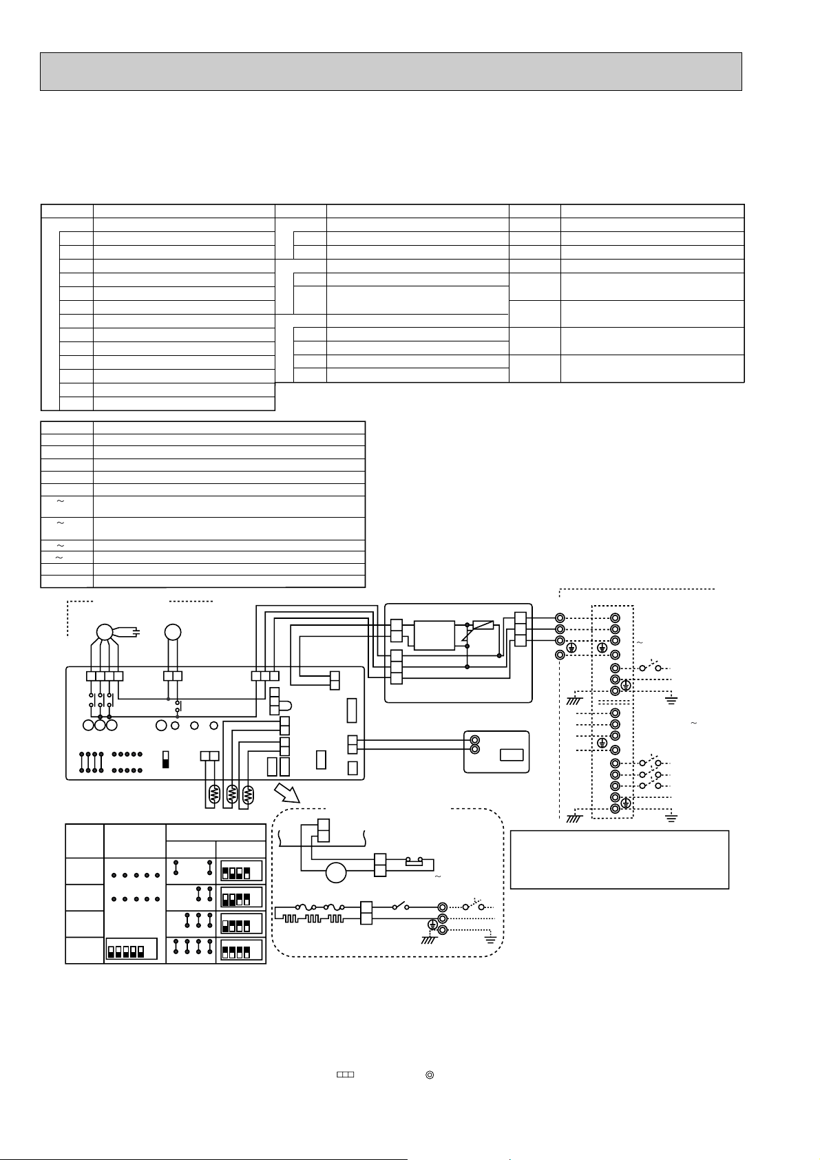
Page 13
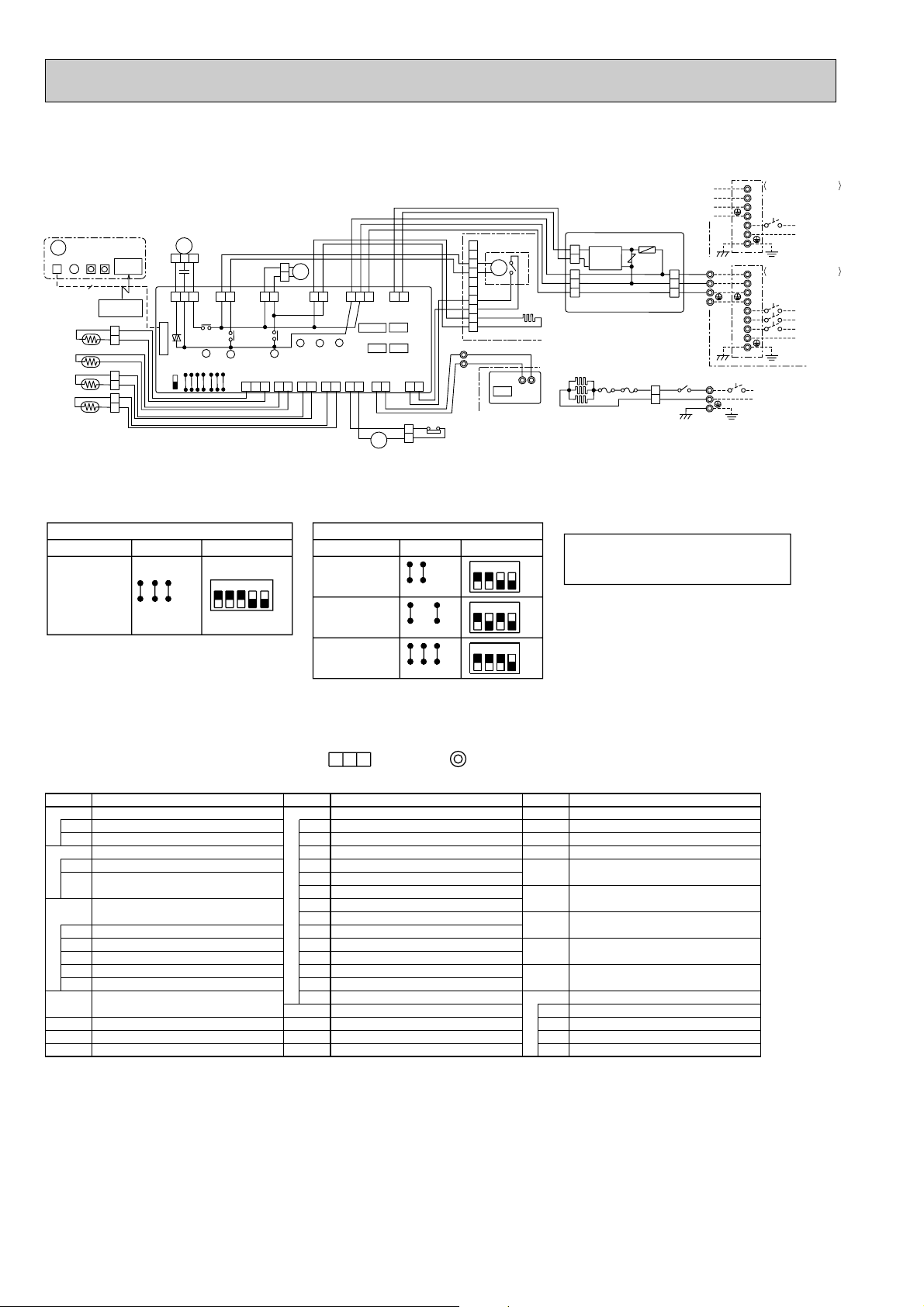
PMH-P1BA, PMH-P1.6BA, PMH-P2BA
(BLU)
REMOTECN90 CN32
12
CN22
CONTROLLER
12346
FAN
(WHT)
LED1
ZNR
T
FUSE
POWER
(RED)
CN03
5
3
1
CN2L
5
LED3
J11
J12
J13
J14
J15
J21
J22
J23
J24
SW2SW1SWE
OFF
ON
1
2
3
4
5
6
PIPE
CN29
(BLK)
1
2
(WHT)
(WHT)
(RED)
(WHT)
CN6V
CN21
CN20
CN31
VANE
INTAKE
LIQUID
D.SENSOR
1
2
1
2
3
2
1
LED2
TH1
TH5
5
4
2
1
MV
3
TH2
CN41
TB6
21
CN2
1
2
TB5
DS
YLW
ORN
RED
GRN
BLU
BLU
ORN
YLW
BRN
BRN
BLK
BLK
BLK
BLK
BLK
BLK
BLK
BLK
R.B
I.B
5
MF
TRANSMISSION WIRES DC14V
TB1
S2
S3
S1
L
N
TB1
S1
S3
S2
N
L3
L2
L1
S3
TB4
S2
S1
OUTDOOR UNIT
<PUH-P1.6, 2VGA>
<PUH-P1, 1.6, 2VGAA.UK>
POWER SUPPLY
~(1PHASE)
220 - 230 - 240V 50Hz
<PUH-P1.6, 2YGA>
<PUH-P1.6, 2YGAA.UK>
POWER SUPPLY
3N~(3PHASE 4WIRES)
380 - 400 - 415V 50Hz
See fig : w1
TRANSFORMER
T
[LEGEND]
NAME
SYMBOL
VARISTOR
POWER SUPPLY (R.B)
TRANSMISSION (INDOOR-OUTDOOR)
JUMPER WIRE (MODEL SELECTION)
JUMPER WIRE (CAPACITY CODE)
SWITCH (EMERGENCY OPERATION)
POWER SUPPLY (I.B)
RELAY (DRAIN PUMP)
FUSE (6.3A, 250V)
CONNECTOR (REMOTE SWITCH)
CONNECTOR (LOSSNAY)
CONNECTOR (HA TERMINAL-A)
INDOOR CONTROLLER BOARD
ZNR
LED1
LED2
LED3
SW1
SW2
SWE
X1
FUSE
CN2L
CN32
CN41
I.B
REMOTE CONTROLLER BOARD
CONNECTOR (PROGRAM TIMER)
TERMINAL BLOCK
(REMOTE CONTROLLER TRAMSMISSION LINE)
R.B
CN2
TB6
DP
DS
MF
MV
VANE MOTOR
DRAIN SENSOR
FAN MOTOR
DRAIN-UP MACHINE
(INDOOR/OUTDOOR CONNECTING LINE)
TERMINAL BLOCK
TERMINAL BLOCK
(REMOTE CONTROL TRANSMISSION LINE)
ROOM TEMPERATURE THERMISTOR
(0°C/15K", 25°C/5.4K" DETECT)
PIPE TEMPERATURE THERMISTOR/LIQUID
CONDENSER/EVAPORATOR TEMPERATURE
THERMISTOR (0°C/15K", 25°C/5.4K" DETECT)
(0°C/15K", 25°C/5.4K" DETECT)
TH5
TH2
TH1
TB5
TB4
BLU
BLU
DP
3
1
D.U.M
CNP
(YLW)
X1
X1
Please set the voltage using the remote controller.
For the setting method, please refer to the indoor unit Installation Manual.
NOTES:
1.Since the outdoor side electric wiring may change be sure to check
the outdoor unit electric wiring for servicing.
2.Indoor and outdoor connecting wires are made with polarities, make
wiring matching terminal numbers(S1, S2, S3).
3.Symbols used in wiring diagram above are, :Connector, :Terminal (block).
<w1>
SW2
ON
OFF
4231
ON
OFF
45231
J21 J22 J23 J24
ON
OFF
4231
ON
OFF
4231
J21 J22 J23 J24
J21 J22 J23 J24
PMH-P1BA
PMH-P1BA
1
PMH-P1BA2
PMH-P1.6BA
PMH-P1.6BA
1
PMH-P1.6BA2
PMH-P2BA
PMH-P2BA
1
PMH-P2BA2
J11 J12 J13 J14 J15 J11 J12 J13 J14 J15
PMH-P1/1.6/2BA
PMH-P1/1.6/2BA
1
SW1
J11 J12 J13 J14 J15
PMH-P1/1.6/2BA2
MODELS
Manufacture
Service board
PMH-P1BA
1, PMH-P1.6BA1, PMH-P2BA1
PMH-P1BA2, PMH-P1.6BA2, PMH-P2BA2
13
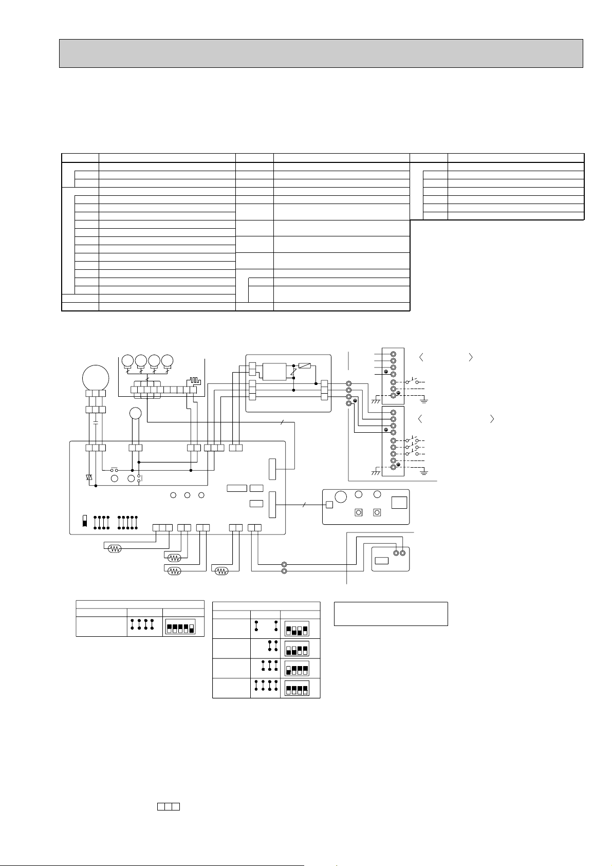
Page 14
PLH-P3AAH.UK, PLH-P4AAH.UK, PLH-P5AAH.UK, PLH-P6AAH.UK
PLH-P3AAH1.UK, PLH-P4AAH1.UK, PLH-P5AAH1.UK, PLH-P6AAH1.UK
SYMBOL
P.B
F1
ZNR
I.B
CN2L
CN32
CN41
SW1
SW2
SWE
X1
X4
FC
LED1
LED2
LED3
C
MF
123
I.B
RED
FAN
(WHT)
FC
SWE
ON
OFF
INDOOR POWER BOARD
NAME
FUSE(4A)
VARISTOR
INDOOR CONTROLLER BOARD
CONNECTOR(LOSSNAY)
CONNECTOR(REMOTE SWITCH)
CONNECTOR(HA TERMINAL-A)
JUMPER WIRE(MODEL SELECTION)
JUMPER WIRE(CAPACITY CORD)
SWITCH(EMERGENCY OPERATION)
RELAY(DRAIN PUMP)
RELAY(FAN MOTOR)
FAN PHASE CONTROL
POWER SUPPLY(I.B)
POWER SUPPLY(R.B)
TRANSMISSION(INDOOR-OUTDOOR)
CAPACITOR(FAN MOTOR)
FAN MOTOR
GRILLE
MVMV MV MV
5
5
5
5
489510
7
D.HEATER
CNC (RED)
LED3 LED2 LED1
INTAKE
CN20
(RED)
321
12 12
BLK
BLK
H2
YLW
13
MF
321
C
WHT
BLK
D.U.M
CNP
(BLU)
X4
X4
SW2
J24
J23
J22
J21
5
1236
DP
12
YLW
YLW
1135
3
X1
X1
SW1
D.SENSOR
CN31
J14
J13
J12
J11
J15
(WHT)
DS
TH1
TH2
YLW
LIQUID
CN21
(WHT)
BLK
12
BLK
YLW
BRN
ORN
513 21
POWER
CN03
(RED)
TH5
CN2S(WHT)
2
1
3
2
1
CONTROLLER BOARD
CN02 (WHT)
WHT
BLK
POWER
CN2D
(WHT)
CN41 CN2L
CN32
PIPE
REMOCON
CN29
CN22
(BLK)
(BLU)
21
BLU
BLK
BLK
21
SYMBOL
MV
DP
DS
H2
TB2
TB4
TB5
TH1
TH2
TH5
R.B
DC14V
5
VANE
CN6V
(WHT)
WIRELESS
CN90
21
(WHT)
BLU
TB5
2
1
TRANSMISSION WIRES DC14V
VANE MOTOR
NAME
DRAIN-UP MACHINE
DRAIN SENSOR
DEW PREVENTION HEATER
TERMINAL BLOCK(HEATER)
TERMINAL BLOCK(INDOOR/OUTDOOR CONNECTING LINE)
TERMINAL BLOCK(REMOTE
CONTROLLER TRANSMISSION LINE)
ROOM TEMP.THERMISTOR
(0:/15k",25:/5.4k" DETECT)
PIPE TEMP .THERMIST OR/LIQUID
(0:/15k",25:/5.4k" DETECT)
COND./EVA.TEMP.THERMISTOR
(0:/15k",25:/5.4k" DETECT)
REMOTE CONTROLLER BOARD
CN2
CONNECTOR(PROGRAM TIMER)
TB6
TERMINAL BLOCK(REMOTE
CONTROLLER TRANSMISSION LINE)
F1
ZNR
OUTDOOR UNIT
CN01 (BLU)
9
1
2
3
W.B
CNB
YLW
ORN
BRN
P.B
BZ
OUTDOOR UNIT
TB4
S1
S2
S3
LED2
LED1
SW2SW1
S1
S2
S3
S1
S2
S3
CN2
TB1
L
N
PE
TB1
L1
L2
L3
N
PE
RU
R.B
21
TB6
PUH-P3VGA
<
PUH-P3, 4VGAA.UK
Y
POWER SUPPL
~ / N (1PHASE)
220-240V 50Hz
PUH-P3YGA~6YGA
<
PUH-P3YGAA.UK~6YGAA.UK
POWER SUPPLY
3N~(3PHASE 4WIRES)
380-415V 50Hz
>
SYMBOL
W.B
RU
BZ
LED1
LED2
SW1
SW2
HEATER
FS1
FS2
H1
26H
88H
>
Position of 88H.
(For Control box)
WIRELESS REMOTE CONTROLLER BOARD
NAME
RECEIVING UNIT
BUZZER
LED(RUN INDICATOR)
LED(HOT ADJUST)
SWITCH(HEATING ON/OFF)
SWITCH(COOLING ON/OFF)
THERMAL FUSE(72:,16A)
THERMAL FUSE(104:,16A)
HEATER
HEATER THERMAL SWITCH
HEATER CONTACTOR
HEATER
CN24
(YLW)
12
H1
FS2
FS1
88H
RED
5
RED
1
WHT
2
I.B
YLW
YLW
TB2
RED
L
3
BLU
POWER SUPPLY
N
~ / N (1PHASE)
PE
220V-240V 50Hz
88H
C
TB2
TB4
WHT
6
Y
GR
WHT
61
5
88H
26H
PLH-P3,4,5,6AAH.UK
PLH-P3,4,5,6AAH1.UK
SW1
Service boardManufactureMODELS
J15J14J13J12J11
54321
ON
OFF
MODELS
PLH-P3AAH.UK
PLH-P3AAH1.UK
PLH-P4AAH.UK
PLH-P4AAH1.UK
PLH-P5AAH.UK
PLH-P5AAH
PLH-P6AAH.UK
PLH-P6AAH
1
.UK
1
.UK
SW2
Manufacture
J23 J24J21J22
J23 J24J21J22
J24J23J22J21
J24J23J22J21
Service board
1234
1324
1234
1324
Please set the voltage using the
remote controller .
For the setting method,please refer to
the indoor unit Installation Manual.
ON
OFF
ON
OFF
ON
OFF
ON
OFF
NOTE:
1. Since the outdoor side electric wiring may change be sure to check the
outdoor unit electric wiring for servicing.
2. Indoor and outdoor connecting wires are made with polarities,make wiring
matching terminal numbers (S1,S2,S3).
3. Make sure that the main power supply of the booster heater is independent.
4. Symbols used in wiring diagram above are,
/ : Terminal , : Connector.
14
Page 15
PLA-P3AA.UK, PLA-P4AA.UK, PLA-P5AA.UK, PLA-P6AA.UK
NAME
INDOOR POWER BOARD
FUSE(4A)
VARISTOR
INDOOR CONTROLLER BOARD
CONNECTOR(LOSSNAY)
CONNECTOR(REMOTE SWITCH)
CONNECTOR(HA TERMINAL-A)
JUMPER WIRE(MODEL SELECTION)
JUMPER WIRE(CAPACITY CODE)
SWITCH(EMERGENCY OPERATION)
RELAY(DRAIN PUMP)
RELAY(FAN MOTOR)
FAN PHASE CONTROL
POWER SUPPLY(I.B)
POWER SUPPLY(I.B)
TRANSMISSION(INDOOR-OUTDOOR)
CAPACITOR(FAN MOTOR)
FAN MOTOR
SYMBOL
P.B
F1
ZNR
I.B
CN2L
CN32
CN41
SW1
SW2
SWE
X1
X4
FC
LED1
LED2
LED3
C
MF
NAME
VANE MOTOR
DRAIN-UP MACHINE
DRAIN SENSOR
DEW PREVENTION HEATER
TERMINAL BLOCK(INDOOR/OUTDOOR CONNECTING LINE)
TERMINAL BLOCK(REMOTE
CONTROLLER TRANSMISSION LINE)
ROOM TEMP.THERMISTOR
(0:/15k",25:/5.4k" DETECT)
PIPE TEMP .THERMIST OR/LIQUID
(0:/15k",25:/5.4k" DETECT)
COND./EVA.TEMP.THERMISTOR
(0:/15k",25:/5.4k" DETECT)
REMOTE CONTROLLER BOARD
CONNECTOR(PROGRAM TIMER)
TERMINAL BLOCK(REMOTE
CONTROLLER TRANSMISSION LINE)
SYMBOL
MV
DP
DS
H2
TB4
TB5
TH1
TH2
TH5
R.B
CN2
TB6
NAME
WIRELESS REMOTE CONTROLLER BOARD
RECEIVING UNIT
BUZZER
LED(RUN INDICATOR)
LED(HOT ADJUST)
SWITCH(HEATING ON/OFF)
SWITCH(COOLING ON/OFF)
SYMBOL
W.B
RU
BZ
LED1
LED2
SW1
SW2
Please set the voltage using the
remote controller .
For the setting method,please refer to
the indoor unit Installation Manual.
PE
PE
OFF
ON
543
J152J14J13J12J11
1
PLA-P3,4,5,6AA
S3
S2
S1
TB4
F1
P.B
123
I.B
MF
C
J24
J23
J22
J21
OFF
ON
2
1
1135
FC
3
DP
ZNR
LED3 LED2 LED1
12 12
J14
J13
J12
J11
21
3
2
1
DC14V
1
2
3
DS
TH2
CN2
TB6
21
1
TB5
2
TH1
513 21
321
CN41 CN2L
CN32
13
5
X1
X1
9
R.B
PLA-P3AA
1324
J24J23J22J21
1234
ON
OFF
J23 J24J21J22
OFF
ON
J15
X4
X4
SW2SW1
RU
BZ
LED2
LED1
W.B
CNB
WHT
RED
BLK
YLW
YLW
YLW
YLW
BRN
ORN
YLW
WHT
BLK
CN2S(WHT)
OUTDOOR UNIT
CN01 (BLU)
CONTROLLER BOARD
CN02 (WHT)
YLW
ORN
BRN
FAN
(WHT)
D.U.M
CNP
(BLU)
D.HEATER
CNC (RED)
D.SENSOR
CN31
(WHT)
INTAKE
CN20
(RED)
LIQUID
CN21
(WHT)
POWER
CN2D
(WHT)
POWER
CN03
(RED)
VANE
CN6V
(WHT)
SWE
SW2
SW1
WIRELESS
CN90
(WHT)
REMOCON
CN22
(BLU)
PIPE
CN29
(BLK)
21
TH5
BLU
BLU
BLK
BLK
BLK
BLK
BLK
BLK
SW1
Service boardManufactureMODELS
TRANSMISSION WIRES DC14V
S1
S2
S3
L1
L2
L3
N
S1
S2
S3
L
N
OUTDOOR UNIT
PU(H)-P3VGA
PU(H)-P3,4VGAA.UK
POWER SUPPL
~ / N (1PHASE)
220-240V 50Hz
POWER SUPPLY
3N~(3PHASE 4WIRES)
380-415V 50Hz
TB1
TB1
Service board
Manufacture
MODELS
SW2
PLA-P4AA
PLA-P5AA
PLA-P6AA
J23 J24J21J22
J24J23J22J21
1234
ON
OFF
1324
OFF
ON
5
5
5
5
MVMV MV MV
GRILLE
5
H2
321
1236
7
489510
NOTE:
1. Since the outdoor side electric wiring may change be sure to check the
outdoor unit electric wiring for servicing.
2. Indoor and outdoor connecting wires are made with polarities,make wiring
matching terminal numbers (S1,S2,S3).
3. Symbols used in wiring diagram above are,
/ : Terminal , : Connector.
Y
PU(H)-P3YGA~6YGA
PU(H)-P3YGAA.UK~6YGAA.UK
PLA-P3AA1.UK, PLA-P4AA1.UK, PLA-P5AA1.UK, PLA-P6AA1.UK
PLA-P3AA, PLA-P4AA, PLA-P5AA, PLA-P6AA
15
Page 16
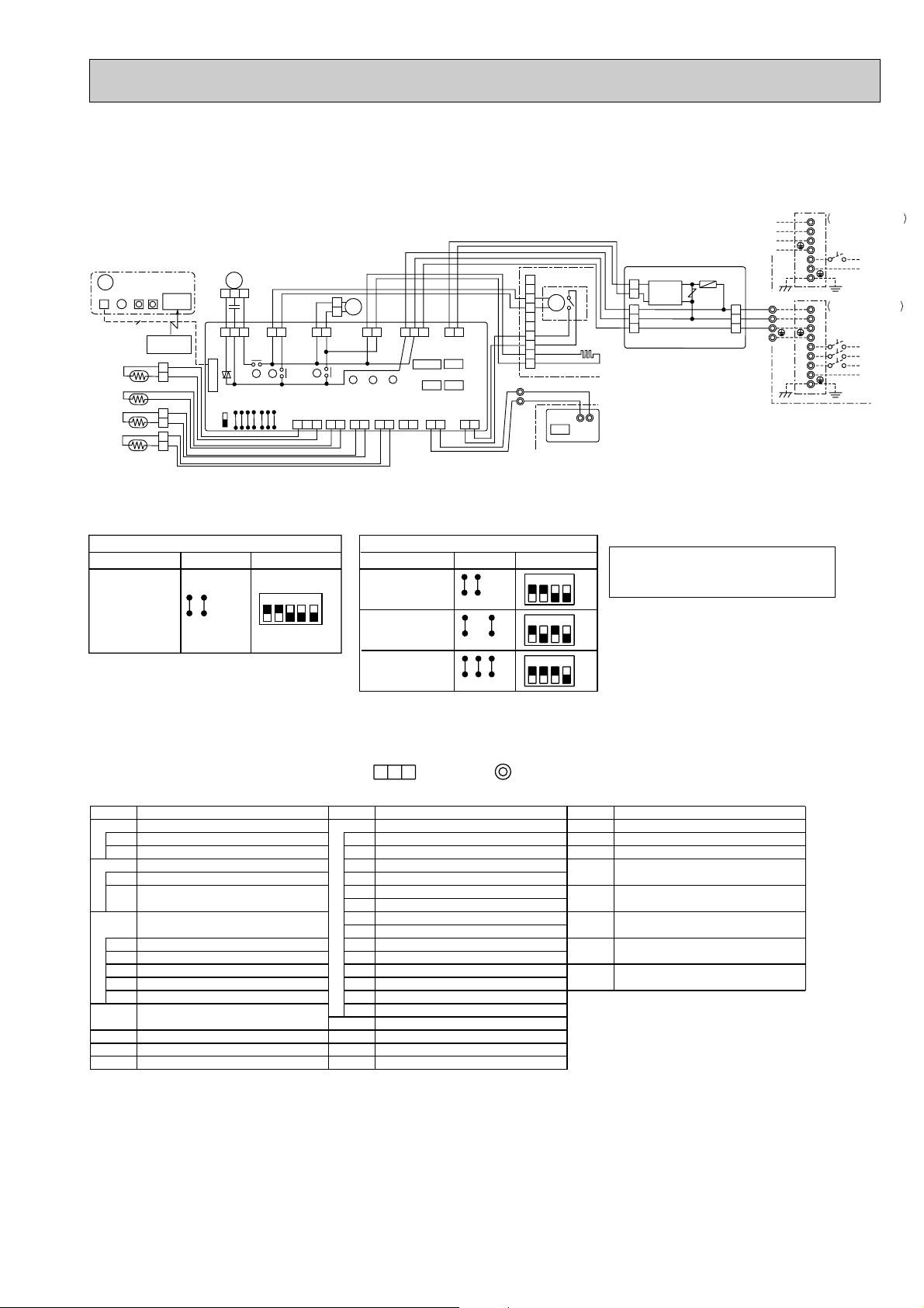
PLH-P1.6KAH.UK, PLH-P2KAH.UK, PLH-P2.5KAH.UK
PLH-P1.6KAH1.UK, PLH-P2KAH1.UK, PLH-P2.5KAH1.UK
W.B
BZ
CNB
LED1
DS
TH1
TH2
TH5
SW1
9
W.R
SW2
REMOTE
CONTROLLER
BLK
1
BLK
3
BLK
1
BLK
2
BLK
1
BLK
2
RU
I.B
FAN
(WHT)
CN90
(WHT)
WIRELESS
ON
OFF
FC
SWE
MF
3
2
1
C
YLW
YLW
WHT
BLK
RED
VANE
5
3
1
J21
3
1
CNV
(GRN)
X4
X3
X4
X3
SW1
SW2
J11
J12
J13
J14
J15
J23
J24
J22
D.U.M
CNP
(BLU)
D.SENSOR
CN31
(WHT)
2
1
1
DP
2
BLU
RED
3
X1
INTAKE
CN20
(RED)
1
D.HEATER
CNC
(RED)
LED3
2
LIQUID
CN21
(WHT)
1
BLU
3
1
POWER
CN03
(RED)
LED1
LED2
PIPE
HEATER
CN29
CN24
(BLK)
(YLW)
2
1
2
RED
1
X1
3
YLW
1
1
YLW
BRN
ORN
5
3
CN41
CN25
REMOTE
CONTROLLER
CN22 (BLU)
2
YLW
1
1
BLU
88H
BLK
WHT
1
POWER
CN2D (WHT)
CN2L
CN32
POSITION
CN23 (GRN)
2
BLU
6
GRY
2
VANE
1
BRN
6
5
WHT
WHT
2
BRN
8
9
2
7
3
4
5
10
1
6
2
TRANSMISSION WIRES DC12V
1
TB5
26H
GRILLE
MV
CN2
LS
H2
1
TB6
2
R.B
CN2S(WHT)
2
DC14V
1
3
2
1
CONTROLLER BOARD
CN02 (WHT)
H1
FS2
ZNR
OUTDOOR UNIT
FS1
RED
WHT
F1
CN01 (BLU)
RED
1
2
P.B
1
2
3
5
YLW
ORN
BRN
88H
3
GRN/YLW
RED
BLU
TB4
S1
S2
S3
TB2
L
N
PE
OUTDOOR UNIT
S1
S2
S3
TB1
S1
S2
S3
TB1
PU(H)-P1.6, 2, 2.5VGA
PU(H)-P1.6, 2, 2.5VGAA.UK
POWER SUPPLY
~/N(1PHASE)
220-240V 50Hz
L
N
PE
PUH-P1.6, 2, 2.5YGA
PU(H)-P1.6, 2, 2.5YGAA.UK
POWER SUPPLY
3N~(3PHASE 4WIRES)
380-415V 50Hz
L1
L2
L3
N
PE
POWER SUPPLY
~/N(1PHASE)
220V-240V 50Hz
(1)
(1)
MODELS
Manufacture
PLH-P1.6KAH.UK
PLH-P1.6KAH1.UK
PLH-P2KAH.UK
PLH-P2KAH1.UK
PLH-P2.5KAH.UK
PLH-P2.5KAH1.UK
SW1
J14J13J12J11
Service board
15
J15
432
ON
OFF
PLH-P1.6KAH1.UK
PLH-P2KAH.UK
PLH-P2KAH1.UK
PLH-P2.5KAH.UK
PLH-P2.5KAH1.UK
PLH-P1.6KAH.UK
SW2
Manufacture
J23J24
J22J21
J23J24
J21J22
J23J24J21J22
service boardMODELS
1234
1234
1234
Please set the voltage using the
remote controller. For the setting
method, please refer to the indoor
ON
unit Installation Manual.
OFF
ON
OFF
ON
OFF
NOTES:
1. Since the outdoor side electric wiring may change be sure to check the outdoor unit electric wiring for servicing.
2. Indoor and outdoor connecting wires are made with polarities, make wiring matching terminal numbers(S1,S2,S3).
3. Make sure that the main power supply of the booster heater is independent.
4. Symbols used in wiring diagram above are,
[LEGEND]
SYMBOL
P.B
F1
ZNR
R.B
CN2
TB6
W.B
RU
BZ
LED1
SW1
SW2
W.R
INDOOR POWER BOARD
NAME
FUSE (4A)
VARISTOR
REMOTE CONTROLLER BOARD
CONNECTOR (PROGRAM TIMER)
TERMINAL BLOCK
(REMOTE CONTROLLER TRAMSMISSION LINE)
WIRELESS REMOTE CONTROLLER
BOARD (OPTION)
RECEIVING UNIT
BUZZER
LED (RUN INDICATOR)
SWITCH (HEATING ON/OFF)
SWITCH (COOLING ON/OFF)
WIRELESS REMOTE CONTROLLER
(OPTION)
SYMBOL
I.B
CN2L
CN25
CN32
CN41
FC
LED1
LED2
LED3
SW1
SW2
SWE
X1
X3
X4
C
DP
DS
H2
:Connector, :Terminal block.
INDOOR CONTROLLER BOARD
CONNECTOR (LOSSNAY)
CONNECTOR (HUMIDIFIER)
CONNECTOR (REMOTE SWITCH)
CONNECTOR (HA TERMINAL-A)
FAN PHASE CONTROL
POWER SUPPLY (I.B)
POWER SUPPLY (R.B)
TRANSMISSION (INDOOR-OUTDOOR)
JUMPER WIRE (MODEL SELECTION)
JUMPER WIRE (CAPACITY CODE)
SWITCH (EMERGENCY OPERATION)
RELAY (DRAIN PUMP/D.HEATER)
RELAY (VANE MOTOR)
RELAY (FAN MOTOR)
CAPACITOR (FAN MOTOR)
DRAIN-UP MACHINE
DRAIN SENSOR
DEW PREVENTION HEATER
NAME
SYMBOL
LIMIT SWITCH
LS
FAN MOTOR
MF
VANE MOTOR
MV
TERMINAL BLOCK (HEATER)
TB2
TERMINAL BLOCK
TB4
NAME
(INDOOR/OUTDOOR CONNECTING LINE)
TERMINAL BLOCK
TB5
(REMOTE CONTROLLER TRANSMISSION LINE)
ROOM TEMPERATURE THERMISTOR
TH1
(0;/15K', 25;/5.4K' DETECT)
PIPE TEMPERATURE THERMISTOR/LIQUID
TH2
(0;/15K', 25;/5.4K' DETECT)
CONDENSER/EVAPORATOR TEMPERATURE
TH5
THERMISTOR (0;/15K', 25;/5.4K' DETECT)
HEATER
THERMAL FUSE (98;,10A), (77;,10A)
FS1,2
HEATER
H1
HEATER THERMAL SWITCH
26H
HEATER CONTACTOR
88H
16
Page 17
PLA-P1.6KA.UK, PLA-P2KA.UK, PLA-P2.5KA.UK
9
W.B
2
HEATER
CN24
(YLW)
1
1
2
REMOTE
CONTROLLER
CN22 (BLU)
2
1
VANE
POSITION
CN23 (GRN)
1
2
3
CONTROLLER BOARD
CN02 (WHT)
R.B
OUTDOOR UNIT
CN01 (BLU)
3
1
2
D.U.M
CNP
(BLU)
D.SENSOR
CN31
(WHT)
X4
X3
X1
X4
REMOTE
CONTROLLER
RU
FAN
(WHT)
CN90
(WHT)
WIRELESS
W.R
CNB
SW1
SW2
LED1
BZ
J15
BLK
BLK
BLK
BLK
BLK
BLK
BRN
YLW
ORN
WHT
BLK
BRN
ORN
YLW
BLU
BLU
RED
RED
YLW
YLW
BLK
WHT
RED
PIPE
CN29
(BLK)
2
1
1
2
TH5
GRILLE
4
8
9
6
1
10
5
3
7
2
S1
S3
S2
TB1
L3
PE
L1
L2
N
S1
PE
S3
S2
TB1
L
N
X1
C
MF
3
1
2
5
3
OUTDOOR UNIT
S1
S2
S3
TB4
P.B
ZNR
2
1
F1
2
CN2
1
TB6
LS
H2
MV
DC14V
1
2
TB5
2
1
CN2S(WHT)
CN32
CN2L
1
2
POWER
CN2D (WHT)
LIQUID
CN21
(WHT)
2
1
INTAKE
CN20
(RED)
2
1
1
2
3
SW2
J22
J23
J24
VANE
CNV
(GRN)
X3
SW1
J11
J12
J13
3
1
3
1
J14
3
1
LED1
LED2
1
D.HEATER
CNC
(RED)
LED3
CN41
3
5
POWER
CN03
(RED)
DP
1
FC
I.B
SWE
ON
OFF
J21
TH2
2
DS
3
1
1
TH1
CN25
TRANSMISSION WIRES DC12V
PUH-P1.6, 2, 2.5YGA
(1)
PUH-P1.6, 2, 2.5YGAA.UK
POWER SUPPLY
3N~(3PHASE 4WIRES)
380-415V 50Hz
PU(H)-P1.6, 2, 2.5VGA
(1)
PU(H)-P1.6, 2, 2.5VGAA.UK
POWER SUPPLY
~/N(1PHASE)
220-240V 50Hz
BLU
BLU
BRN
BRN
SW2
Manufacture
service boardMODELS
J23J24
1234
ON
OFF
1234
ON
OFF
J23J24
J22J21
J21J22
PLA-P1.6KA.UK
PLA-P1.6KA
1
.UK
PLA-P2KA.UK
PLA-P2KA
1
.UK
PLA-P2.5KA.UK
PLA-P2.5KA
1
.UK
1234
ON
OFF
J23J24J21J22
Please set the voltage using the
remote controller. For the setting
method, please refer to the indoor
unit Installation Manual.
1. Since the outdoor side electric wiring may change be sure to check the outdoor unit electric wiring for servicing.
3. Make sure that the main power supply of the booster heater is independent.
4. Symbols used in wiring diagram above are,
2. Indoor and outdoor connecting wires are made with polarities, make wiring matching terminal numbers(S1,S2,S3).
:Connector, :Terminal block.
NOTES:
NAME
NAME
SYMBOL
INDOOR CONTROLLER BOARD
NAME
SYMBOL
INDOOR POWER BOARD
VARISTOR
FUSE (4A)
[LEGEND]
F1
REMOTE CONTROLLER BOARD
CONNECTOR (PROGRAM TIMER)
R.B
CN2
ZNR
P.B
CONNECTOR (REMOTE SWITCH)
CONNECTOR (LOSSNAY)
CN2L
CN32
CN41
CONNECTOR (HA TERMINAL-A)
LED1
LED2
POWER SUPPLY (R.B)
LED3
TRANSMISSION (INDOOR-OUTDOOR)
JUMPER WIRE (MODEL SELECTION)
SW1
JUMPER WIRE (CAPACITY CODE)
SW2
SWITCH (EMERGENCY OPERATION)
SWE
I.B
POWER SUPPLY (I.B)
CONNECTOR (HUMIDIFIER)
CN25
FC
FAN PHASE CONTROL
X1
RELAY (DRAIN PUMP/D.HEATER)
X3
RELAY (VANE MOTOR)
X4
RELAY (FAN MOTOR)
TERMINAL BLOCK
TB6
(REMOTE CONTROLLER TRAMSMISSION LINE)
W.B
BZ
RU
BOARD (OPTION)
RECEIVING UNIT
BUZZER
SW1
LED1
SWITCH (HEATING ON/OFF)
LED (RUN INDICATOR)
SW2
SWITCH (COOLING ON/OFF)
WIRELESS REMOTE CONTROLLER
W.R
WIRELESS REMOTE CONTROLLER
(OPTION)
SYMBOL
DRAIN-UP MACHINE
DRAIN SENSOR
DEW PREVENTION HEATER
CAPACITOR (FAN MOTOR)
DP
H2
C
DS
ROOM TEMPERATURE THERMISTOR
TERMINAL BLOCK
FAN MOTOR
TERMINAL BLOCK
(REMOTE CONTROLLER TRANSMISSION LINE)
LIMIT SWITCH
VANE MOTOR
(0;/15K', 25;/5.4K' DETECT)
(INDOOR/OUTDOOR CONNECTING LINE)
LS
MF
MV
TB5
TB4
TH1
CONDENSER/EVAPORATOR TEMPERATURE
THERMISTOR (0;/15K', 25;/5.4K' DETECT)
PIPE TEMPERATURE THERMISTOR/LIQUID
(0;/15K', 25;/5.4K' DETECT)
TH2
TH5
SW1
Service board
Manufacture
MODELS
OFF
ON
43215
J14J13J12J11 J15
PLA-P1.6KA.UK
PLA-P2KA.UK
PLA-P2.5KA.UK
PLA-P1.6KA
1
.UK
PLA-P2KA
1
.UK
PLA-P2.5KA
1
.UK
PLA-P1.6KA1.UK, PLA-P2KA1.UK, PLA-P2.5KA1.UK
17
Page 18
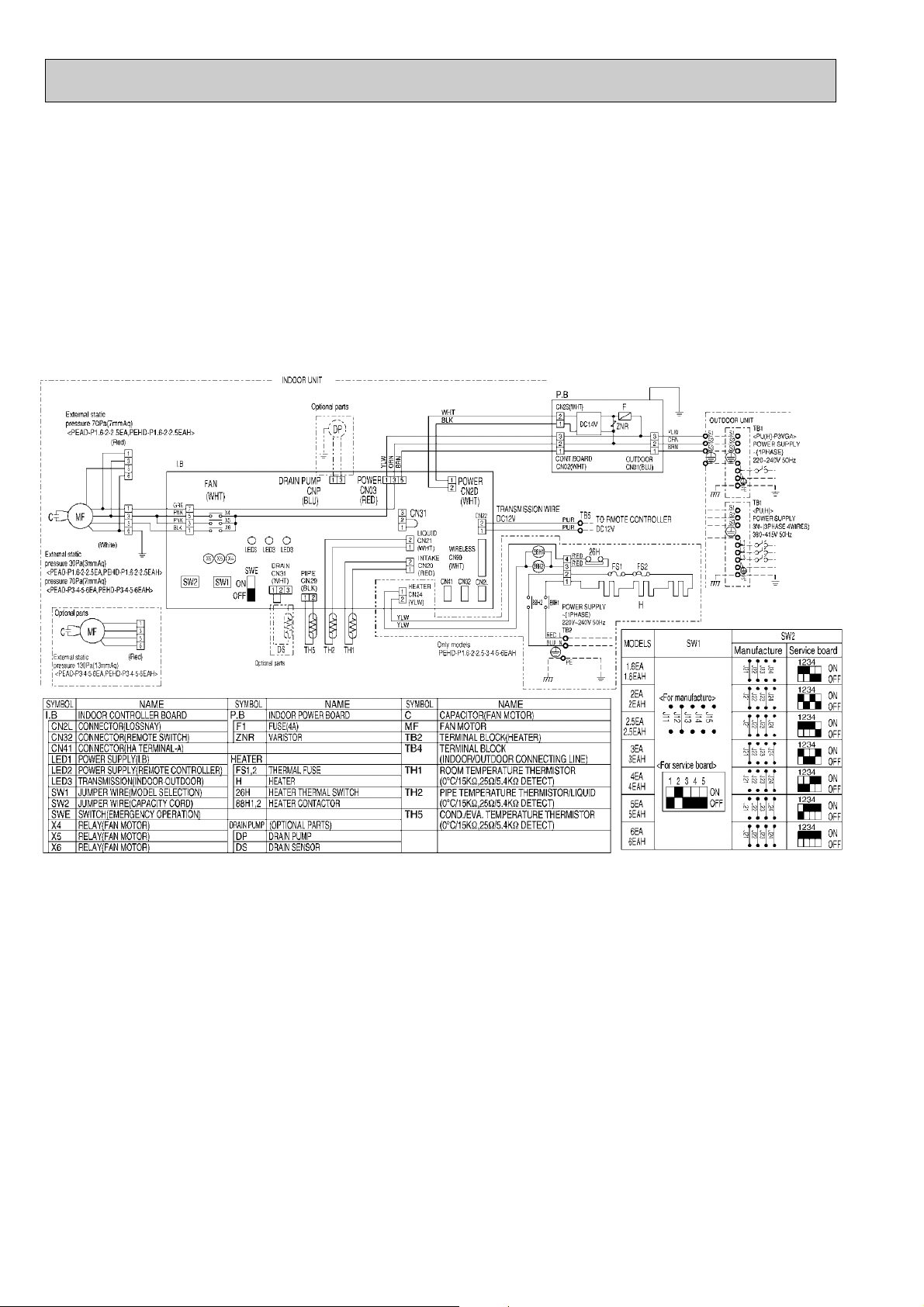
PEHD-P1.6EAH.UK,PEHD-P2EAH.UK,PEHD-P2.5EAH.UK,PEHD-P3EAH.UK
PEHD-P1.6EAH1.UK,PEHD-P2EAH1.UK,PEHD-P2.5EAH1.UK,PEHD-P3EAH1.UK
PEHD-P4EAH.UK,PEHD-P5EAH.UK,PEHD-P6EAH.UK
PEHD-P4EAH1.UK,PEHD-P5EAH1.UK,PEHD-P6EAH1.UK
PEAD-P1.6EA.UK,PEAD-P2EA.UK,PEAD-P2.5EA.UK,PEAD-P3EA.UK
PEAD-P1.6EA1.UK,PEAD-P2EA1.UK,PEAD-P2.5EA1.UK,PEAD-P3EA1.UK
PEAD-P4EA.UK,PEAD-P5EA.UK,PEAD-P6EA.UK
PEAD-P4EA1.UK,PEAD-P5EA1.UK,PEAD-P6EA1.UK
18
Page 19
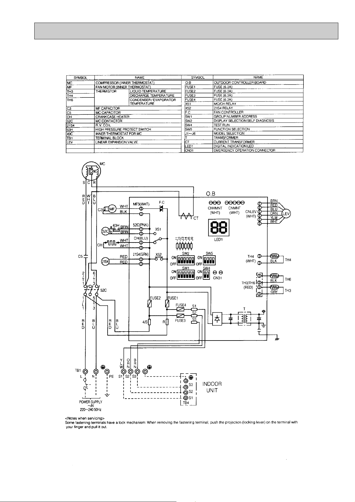
PUH-P1.6 / 2 / 2.5 / 3VGA
PUH-P2.5VGA1
19
Page 20
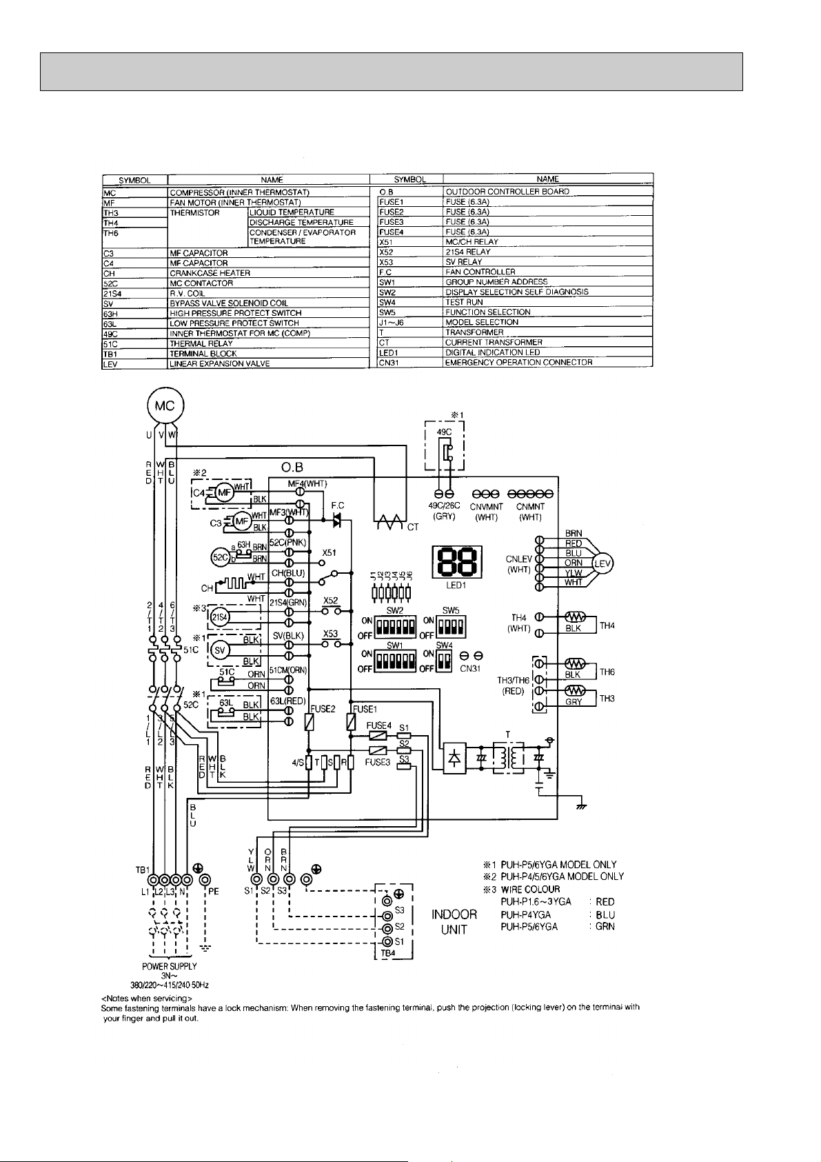
PUH-P1.6 / 2 / 2.5 / 3 / 4 / 5 / 6YGA
PUH-P2.5YGA1
20
Page 21
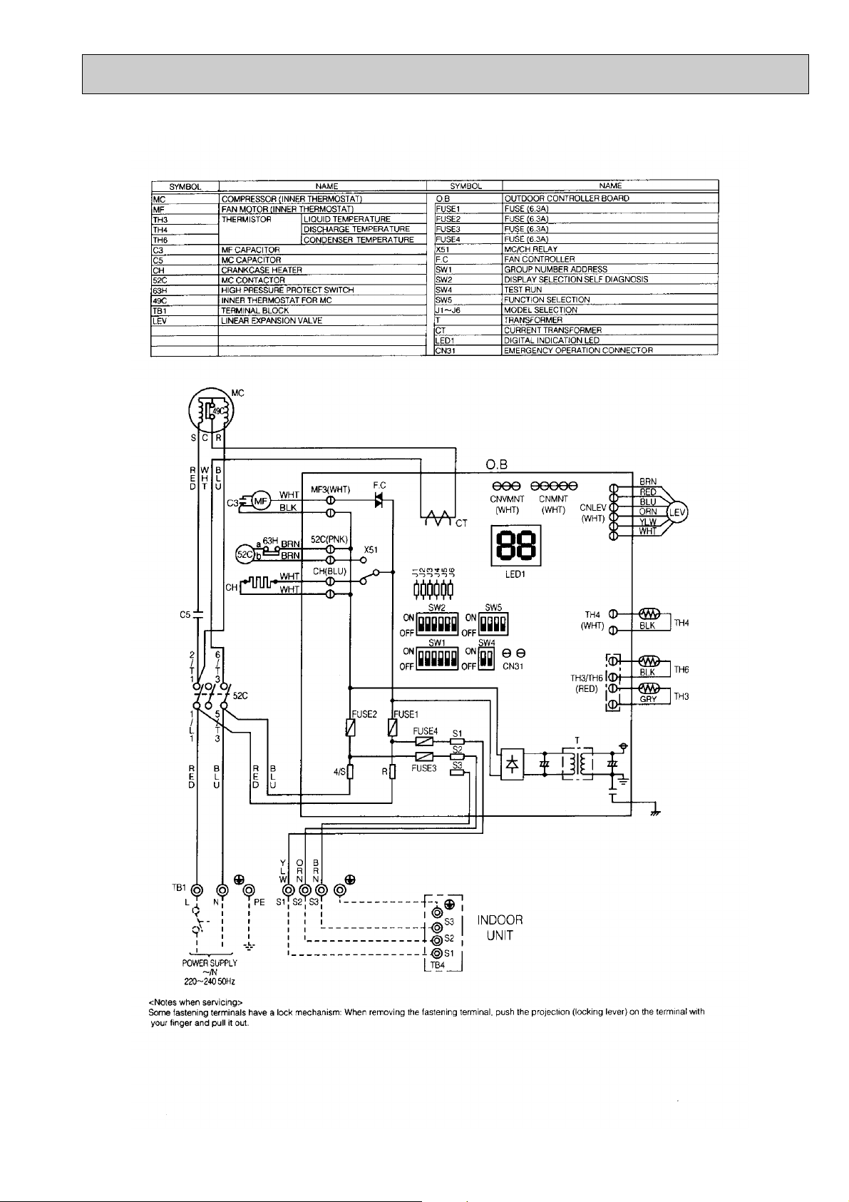
PU-P1.6 / 2 / 2.5 / 3VGA
PU-P2.5VGA1
21
Page 22
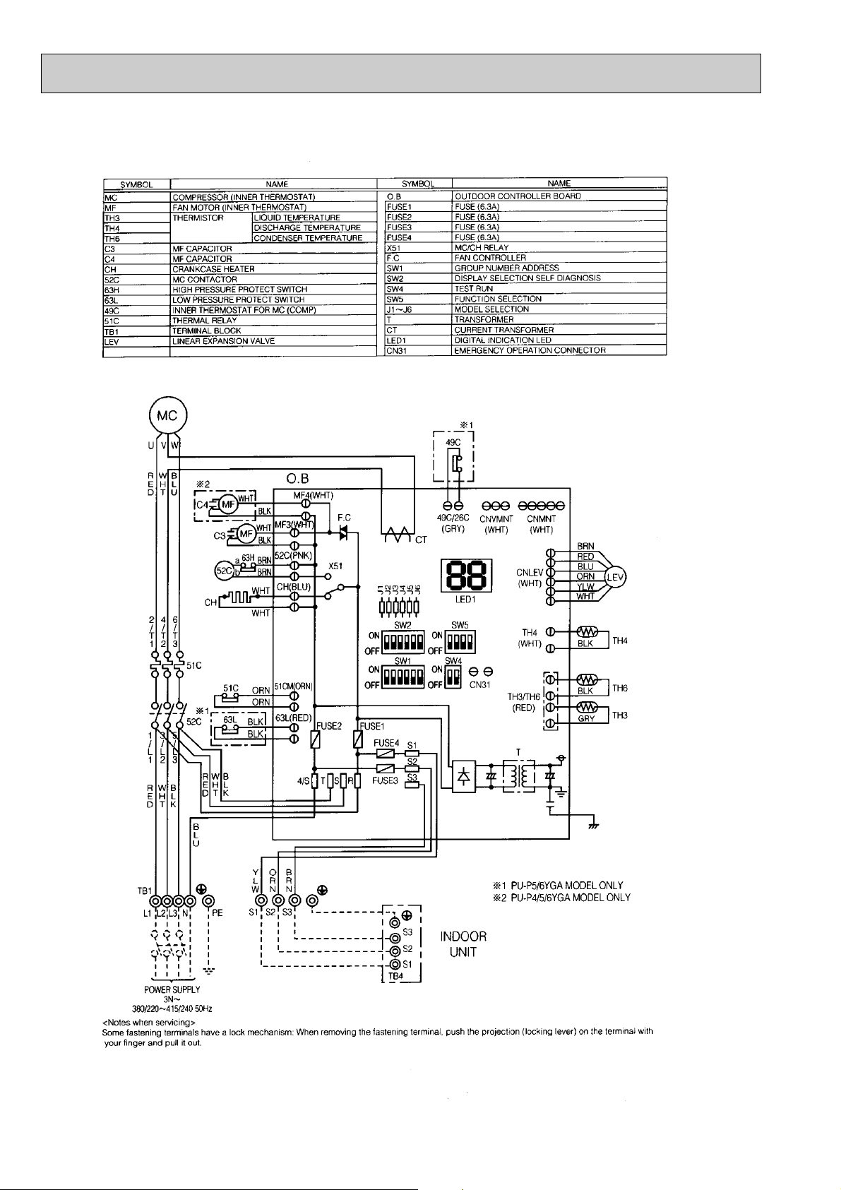
PU-P3 / 4 / 5 / 6YGA
22
Page 23
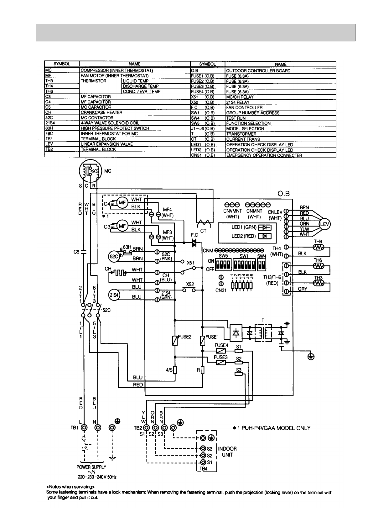
PUH-P1, 1.6, 2, 2.5, 3, 4VGAA.UK
23
Page 24
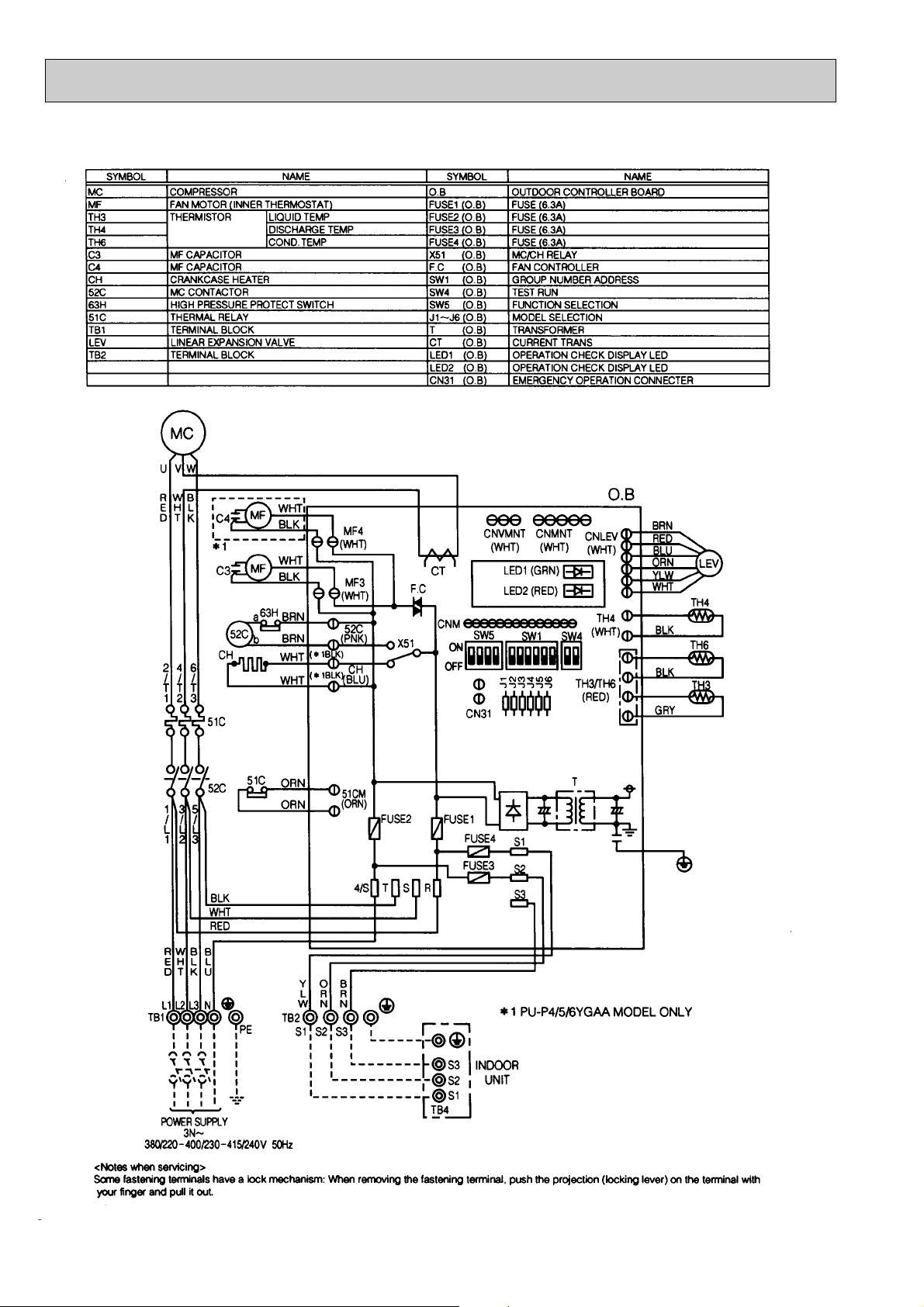
PUH-P1.6, 2, 2.5, 3, 4, 5, 6YGAA.UK
24
Page 25
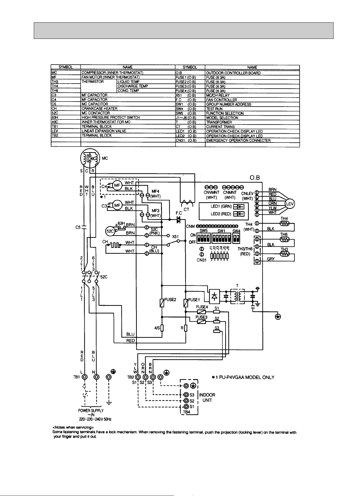
PU-P1.6, 2, 2.5, 3, 4VGAA.UK
25
Page 26
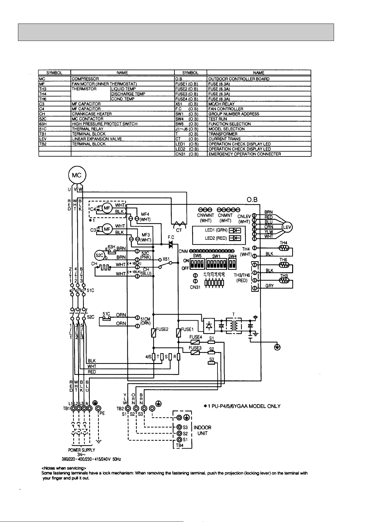
PU-P 1.6, 2, 2.5, 3, 4, 5, 6YGAA.UK
26
Page 27
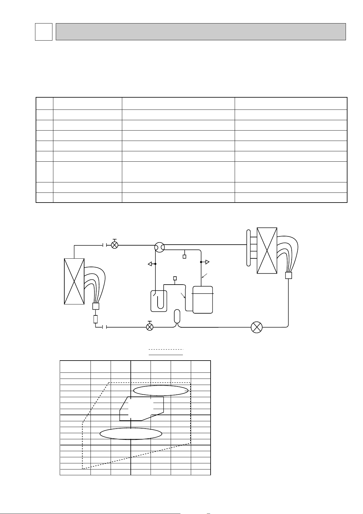
4
Measurement item
COOL: 1.8 ~ 2.4 HEAT: 1.8 ~ 2.6
0.33 ~ 0.55
72 ~ 105
-2 ~ 14
COOL: 27: HEAT: 20:
COOL: 8 ~ 12
HEAT: 40 ~ 50
COOL: 35 HEAT: 7
COOL: 40 ~ 50 HEAT: 0 ~ 16
Measurement method, remarks
Connect the pressure gauge to the high-pressure check valve.
Connect the pressure gauge to the low-pressure check valve.
Measure with piping surface thermometer.
Measure with piping surface thermometer.
Can be displayed on remote controller.
Measure with piping surface thermometer.
Measure with piping surface thermometer.
High pressure (MPa)
Low pressure (MPa)
Discharge pipe temperature (:)
Suction pipe temperature (:)
Indoor intake temperature (:)
Indoor outlet temperature (:)
Outdoor intake temperature (:)
Outdoor outlet temperature (:)
Pressure/temperature near JIS
standard operating conditions
A
B
C
D
E
F
G
H
When outdoor units (P1 to P6) and indoor units (P1 to P6) are combined in a proportion of 1:1 ("Hi" notch on indoor unit)
Gas pipe
Ball valve
4-way valve
Outdoor heat exchanger
63H
(High pressure switch)
63L(Low pressure switch)
Indoor heat exchanger
Accumulator
Liquid pipe
Stop valve
LEV
Drier
Compressor
A
B
C
D
Overload operation
Low-pressure operation
Standard
operation
range
Permissible operation range
Normal operation range
0.2 0.4 0.6 0.8
Intake pressure (MPa)
1.0
Discharge pressure (MPa)
2.0
3.0
3.3
Operation pressure ranges
REFRIGERANT SYSTEM DIAGRAM
•Checking operation statuses
Measurement points and items
•The table and diagrams below show the measurement item for each measurement point, and the pressure and temperature
near the JIS standard operating conditions.
•Measure the temperature and pressure of each part by following the descriptions in the table.
•Measurement time: Be sure to wait until the refrigerant circuit has stabilized (30 minutes to 1 hour) before taking
measurements.
27
Note 1: When draining the outdoor
unit's refrigerant, you must
attach a new drier amid the
extension piping. Be sure you
have the drier specified for
your model before beginning
the operation. The drier
model used with R22 can't be
used.
Page 28
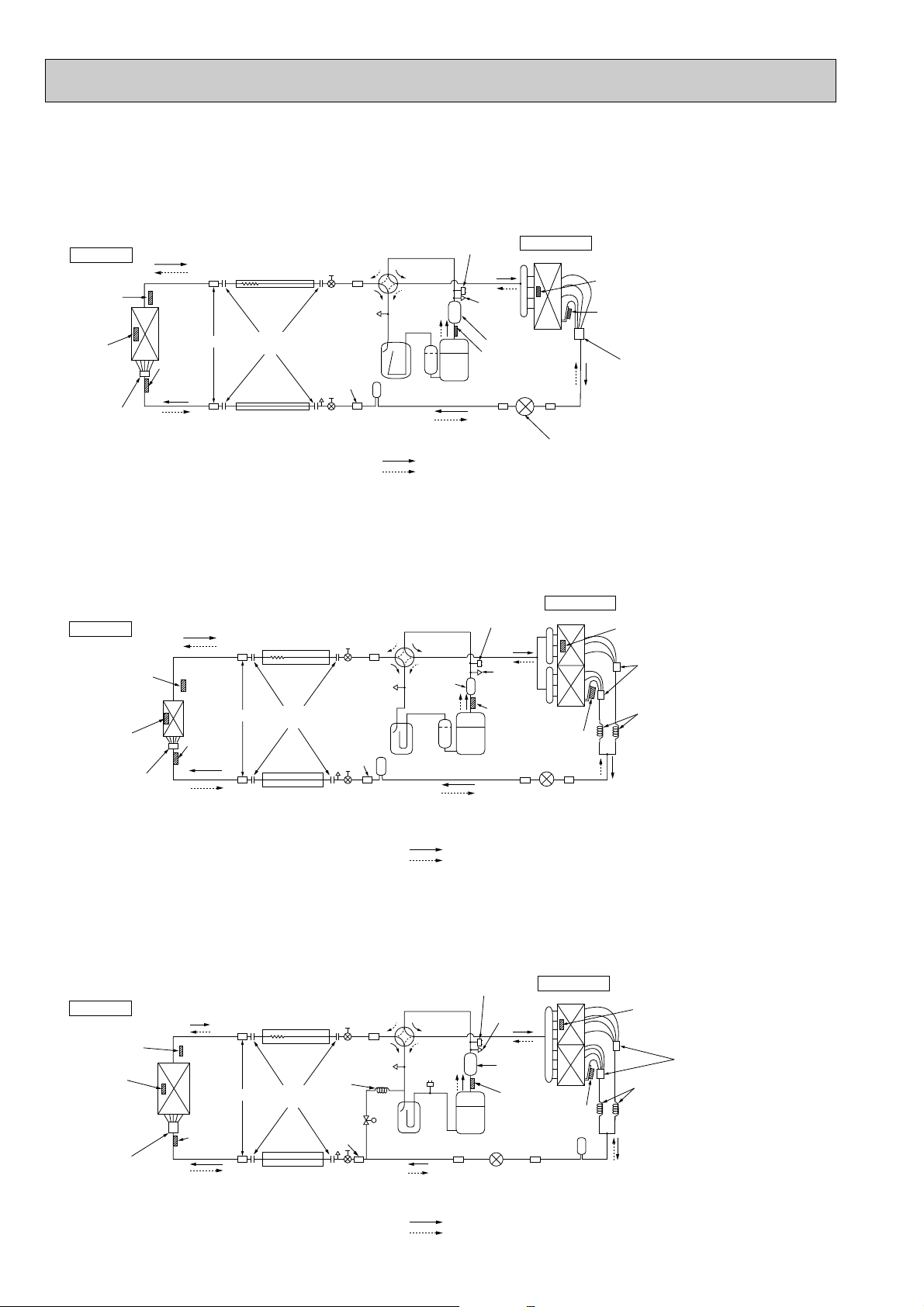
Indoor unit
Outdoor unit
Thermistor
(TH2)
Strainer
Flexible tube
Service
port
Accumulator
Ball valve
Strainer
Compressor
Refrigerant pipe
19.05A({3/4")
(with heat insulator)
Refrigerant pipe
9.52A({3/8")
(with heat insulator)
Ball valve
(with service port)
Strainer
4-way valve
Service
port
High pressure
protect switch
Thermistor
(TH3)
Capillary tube
(O.D.4.0✕I.D.3.0-R200)✕2pcs
Distributor
with
strainer
Flared
connection
Drier
Strainer
Linear expansion valve
Bypass
valve
Thermistor
(TH5)
Thermistor
(TH1)
Low
pressure
protect
switch
Muffler
Thermistor
(TH4)
Thermistor
(TH6)
Distributor
with
strainer
Strainer
Capillary
tube w1
Refrigerant flow in cooling
Refrigerant flow in heating
w1 : O.D.4.0✕I.D.2.0-R250(PUH-P6YGA)
O.D.4.0✕I.D.2.0-R400(PUH-P5YGA)
Indoor unit
Outdoor unit
Thermistor
(TH5)
Strainer
Flexible tube
Service
port
Accumulator
Ball valve
Strainer
Compressor
Refrigerant pipe
19.05A({3/4")
(with heat insulator)
Refrigerant pipe
9.52A({3/8")
(with heat insulator)
Ball valve
(with service port)
Strainer
4-way valve
Service
port
High pressure
protect switch
Thermistor
(TH3)
Capillary tube
(O.D.4.0✕I.D.3.0-R350)✕2pcs
Distributor
with
strainer
Flared
connection
Refrigerant flow in cooling
Refrigerant flow in heating
Strainer
Linear expansion valve
Drier
Thermistor
(TH1)
Indoor coil
thermistor
(TH2)
Thermistor
(TH4)
Muffler
Thermistor
(TH6)
Distributor
with
strainer
Strainer
Indoor unit
Outdoor unit
Thermistor
(TH1)
Strainer
Flared
connection
Flexible tube
Service
port
Accumulator
Ball valve
Strainer
Compressor
Refrigerant pipe
15.88A({5/8")
(with heat insulator)
Refrigerant pipe
9.52A({3/8")
(with heat insulator)
Ball valve
(with service port)
Strainer
4-way valve
Service
port
High pressure
protect switch
Outdoor heat exchanger
Thermistor
(TH3)
Distributor
with
strainer
Thermistor
(TH6)
Distributor
with
strainer
Strainer
Drier
Indoor coil
thermistor
(TH2)
Thermistor
(TH5)
Muffler
Thermistor(TH4)
Linear expansion valve
Strainer
Refrigerant flow in cooling
Refrigerant flow in heating
•Refrigerant Piping System Diagram
PUH-P1.6VGA / PUH-P2VGA / PUH-P2.5VGA / PUH-P2.5VGA1 / PUH-P3VGA
PUH-P1.6YGA / PUH-P2YGA / PUH-P2.5YGA / PUH-P2.5YGA
1 / PUH-P3YGA
<4-way valve solenoid coil>
Heating : ON
Cooling : OFF
PUH-P4YGA
PUH-P5YGA / PUH-P6YGA
28
Page 29
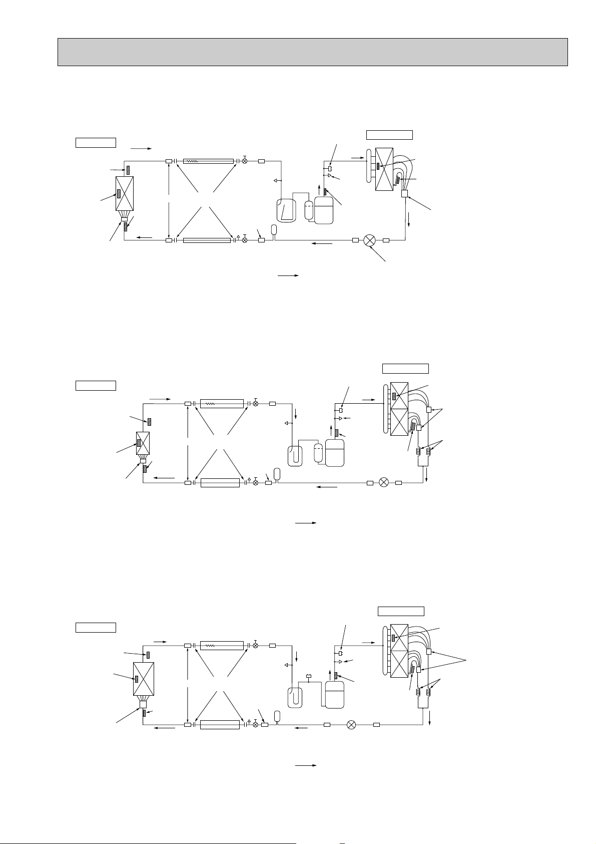
Indoor unit
Outdoor unit
Thermistor
(TH2)
Strainer
Flexible tube
Service
port
Accumulator
Ball valve
Strainer
Compressor
Refrigerant pipe
19.05A({3/4")
(with heat insulator)
Refrigerant pipe
9.52A({3/8")
(with heat insulator)
Ball valve
(with service port)
Strainer
Service
port
High pressure
protect switch
Thermistor
(TH3)
Capillary tube
(O.D.4.0✕I.D.3.0- 200)✕2pcs
Distributor
with
strainer
Flared
connection
Drier
Strainer
Linear expansion valve
Thermistor
(TH5)
Thermistor
(TH1)
Low
pressure
protect
switch
Thermistor
(TH4)
Thermistor
(TH6)
Distributor
with
strainer
Strainer
Refrigerant flow in cooling
Indoor unit
Outdoor unit
Thermistor
(TH5)
Strainer
Flexible tube
Service
port
Accumulator
Ball valve
Strainer
Compressor
Refrigerant pipe
19.05A({3/4")
(with heat insulator)
Refrigerant pipe
9.52A({3/8")
(with heat insulator)
Ball valve
(with service port)
Strainer
4-way valve
Service
port
High pressure
protect switch
Thermistor
(TH3)
Capillary tube
(O.D.4.0✕I.D.3.0-R350)✕2pcs
Distributor
with
strainer
Flared
connection
Refrigerant flow in cooling
Strainer
Linear expansion valve
Drier
Thermistor
(TH1)
Indoor coil
thermistor
(TH2)
Thermistor
(TH4)
Thermistor
(TH6)
Distributor
with
strainer
Strainer
PU-P1.6VGA / PU-P2VGA / PU-P2.5VGA / PU-P2.5VGA1 / PU-P3VGA / PU-P3YGA
Indoor unit
Outdoor unit
Thermistor
(TH1)
Strainer
Flared
connection
Flexible tube
Service
port
Accumulator
Ball valve
Strainer
Compressor
Refrigerant pipe
15.88A({5/8")
(with heat insulator)
Refrigerant pipe
9.52A({3/8")
(with heat insulator)
Ball valve
(with service port)
Strainer
Service
port
High pressure
protect switch
Outdoor heat exchanger
Thermistor
(TH3)
Distributor
with
strainer
Thermistor
(TH6)
Distributor
with
strainer
Strainer
Drier
Indoor coil
thermistor
(TH2)
Thermistor
(TH5)
Thermistor(TH4)
Linear expansion valve
Strainer
Refrigerant flow in cooling
PU-P4YGA
PU-P5YGA / PU-P6YGA
29
Page 30
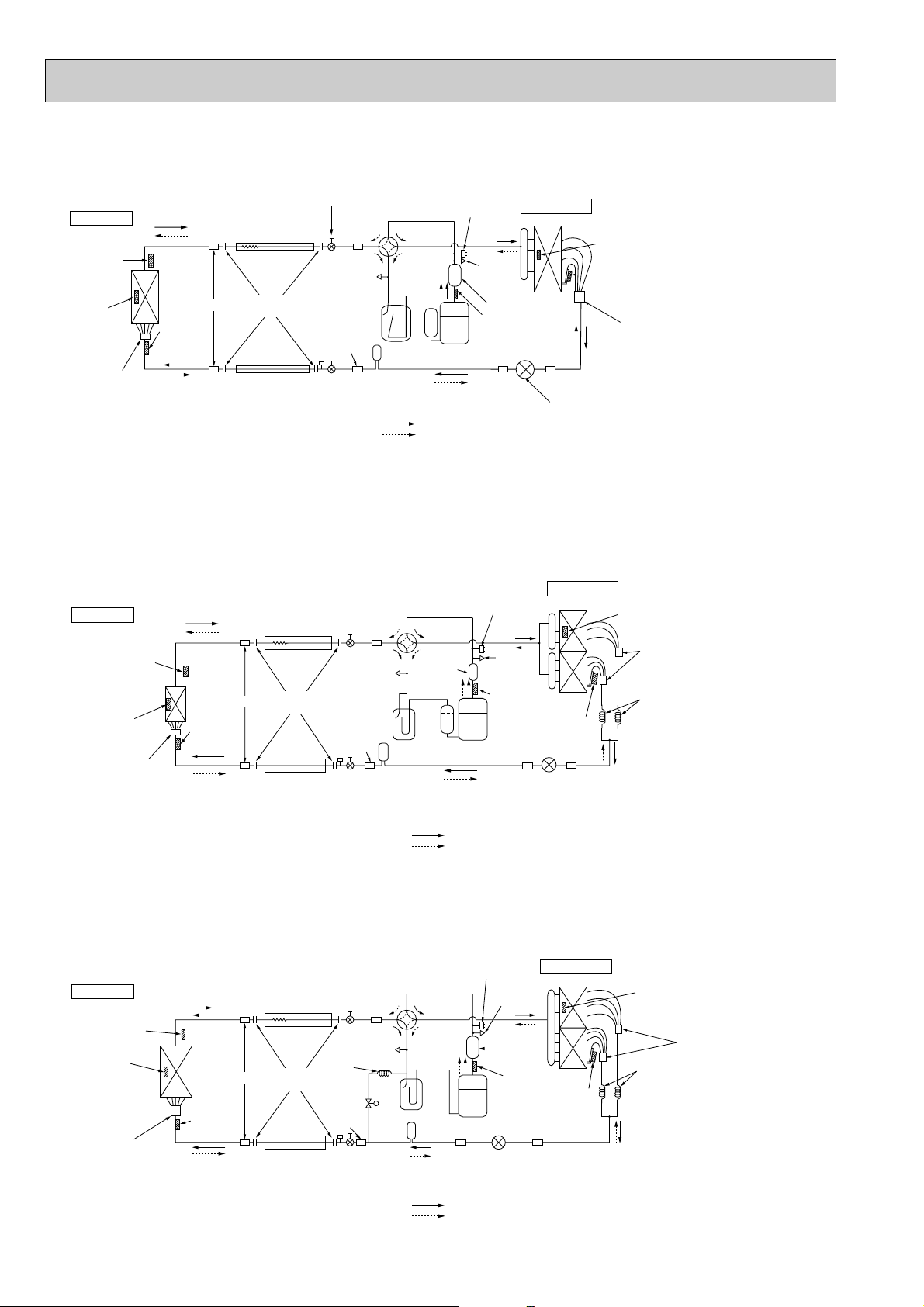
Indoor unit
Outdoor unit
Thermistor
(TH2)
Strainer
Flexible tube
Service
port
Accumulator
Ball valve
Strainer
Compressor
Refrigerant pipe
19.05A({3/4")
(with heat insulator)
Refrigerant pipe
9.52A({3/8")
(with heat insulator)
Stop valve
(with service port)
Strainer
4-way valve
Service
port
High pressure
protect switch
Thermistor
(TH3)
Capillary tube
(O.D.4.0✕I.D.3.0-R200)✕2pcs
Distributor
with
strainer
Flared
connection
Drier
Strainer
Linear expansion valve
Bypass
valve
Thermistor
(TH5)
Thermistor
(TH1)
Muffler
Thermistor
(TH4)
Thermistor
(TH6)
Distributor
with
strainer
Strainer
Capillary
tube w1
Refrigerant flow in cooling
Refrigerant flow in heating
w1 : O.D.4.0✕I.D.2.0-R400(PUH-P5YGAA.UK)
O.D.4.0✕I.D.3.0-R450(PUH-P6YGAA.UK)
Indoor unit
Outdoor unit
Thermistor
(TH5)
Strainer
Flexible tube
Service
port
Accumulator
Ball valve
Strainer
Compressor
Refrigerant pipe
19.05A({3/4")
(with heat insulator)
Refrigerant pipe
9.52A({3/8")
(with heat insulator)
Stop valve
(with service port)
Strainer
4-way valve
Service
port
High pressure
protect switch
Thermistor
(TH3)
Capillary tube
(O.D.4.0✕I.D.3.0-R350)✕2pcs
Distributor
with
strainer
Flared
connection
Refrigerant flow in cooling
Refrigerant flow in heating
Strainer
Linear expansion valve
Drier
Thermistor
(TH1)
Indoor coil
thermistor
(TH2)
Thermistor
(TH4)
Muffler
Thermistor
(TH6)
Distributor
with
strainer
Strainer
PUH-P 1, 1.6, 2, 2.5, 3VGAA.UK
Indoor unit
Outdoor unit
Thermistor
(TH1)
Strainer
Flared
connection
Flexible tube
Service
port
Accumulator
Ball valve
Strainer
Compressor
Refrigerant pipe
P1···12.7A({1/2")
P1.6~P3···15.88A({5/8")
(with heat insulator)
Refrigerant pipe
P1···6.35A({1/4")
P1.6~P3···9.52A({3/8")
(with heat insulator)
Stop valve
(with service port)
Strainer
4-way valve
Service
port
High pressure
protect switch
Outdoor heat exchanger
Thermistor
(TH3)
Distributor
with
strainer
Thermistor
(TH6)
Distributor
with
strainer
Strainer
Drier
Indoor coil
thermistor
(TH2)
Thermistor
(TH5)
Muffler
Thermistor(TH4)
Linear expansion valve
Strainer
Refrigerant flow in cooling
Refrigerant flow in heating
PUH-P1.6, 2, 2.5, 2.5, 3YGAA.UK
PUH-P4VGAA.UK, PUH-P4YGAA.UK
<4-way valve solenoid coil>
Heating : ON
Cooling : OFF
PUH-P5YGAA.UK, PUH-P6YGAA.UK
30
Page 31

Indoor unit
Outdoor unit
Thermistor
(TH2)
Strainer
Flexible tube
Service
port
Accumulator
Ball valve
Strainer
Compressor
Refrigerant pipe
19.05A({3/4")
(with heat insulator)
Refrigerant pipe
9.52A({3/8")
(with heat insulator)
Stop valve
(with service port)
Strainer
Service
port
High pressure
protect switch
Thermistor
(TH3)
Capillary tube
(O.D.4.0✕I.D.3.0- 200)✕2pcs
Distributor
with
strainer
Flared
connection
Drier
Strainer
Linear expansion valve
Thermistor
(TH5)
Thermistor
(TH1)
Thermistor
(TH4)
Thermistor
(TH6)
Distributor
with
strainer
Strainer
Refrigerant flow in cooling
Indoor unit
Outdoor unit
Thermistor
(TH5)
Strainer
Flexible tube
Service
port
Accumulator
Ball valve
Strainer
Compressor
Refrigerant pipe
19.05A({3/4")
(with heat insulator)
Refrigerant pipe
9.52A({3/8")
(with heat insulator)
Stop valve
(with service port)
Strainer
Service
port
High pressure
protect switch
Thermistor
(TH3)
Capillary tube
(O.D.4.0✕I.D.3.0-R350)✕2pcs
Distributor
with
strainer
Flared
connection
Refrigerant flow in cooling
Strainer
Linear expansion valve
Drier
Thermistor
(TH1)
Indoor coil
thermistor
(TH2)
Thermistor
(TH4)
Thermistor
(TH6)
Distributor
with
strainer
Strainer
PU-P1.6, 2, 2.5, 3VGAA.UK
Indoor unit
Outdoor unit
Thermistor
(TH1)
Strainer
Flared
connection
Flexible tube
Service
port
Accumulator
Ball valve
Strainer
Compressor
Refrigerant pipe
15.88A({5/8")
(with heat insulator)
Refrigerant pipe
9.52A({3/8")
(with heat insulator)
Stop valve
(with service port)
Strainer
Service
port
High pressure
protect switch
Outdoor heat exchanger
Thermistor
(TH3)
Distributor
with
strainer
Thermistor
(TH6)
Distributor
with
strainer
Strainer
Drier
Indoor coil
thermistor
(TH2)
Thermistor
(TH5)
Thermistor(TH4)
Linear expansion valve
Strainer
Refrigerant flow in cooling
PU-P1.6, 2, 2.5, 3YGAA.UK
PU-P4VGAA.UK, PU-P4YGAA.UK
PU-P5YGAA.UK, PU-P6YGAA.UK
31
Page 32

5
Parts name Check points
Disconnect the connector then measure the resistance using a tester.
(Surrounding temperature 10:~30:)
Measure the resistance between the terminals using a tester.
(Surrounding temperature 20:~30:)
Drain sensor
(Refer to below for a detail.)
(Refer to below for a detail.)
Room temperature
thermistor (TH1)
Pipe temperature
thermistor (TH2)
Condenser/evaporator
temperature thermistor
(TH5)
1
2
3
Normal
4.3k"~9.6k"
Abnormal
Open or short
Abnormal
Open or short
Normal
0.6k"~6.0k"
-20 0 20406080
< Thermistor for drain sensor >
Temperature (:)
0
1
2
3
4
5
6
7
8
9
10
Resistance (K")
HOW TO CHECK THE PARTS
5-1. Indoor unit
11
Common parts
<Thermistor Characteristic graph>
Thermistor for
lower temperature
Room temperature thermistor(TH1)
Pipe temperature thermistor(TH2)
Condenser/evaporator temperature
thermistor(TH5)
Thermistor R0=15kΩ ±3%
Fixed number of B=3480kΩ ±2%
Rt=15exp { 3480( ) }
1
273+t
0: 15kΩ
10: 9.6kΩ
20: 6.3kΩ
25: 5.2kΩ
30: 4.3kΩ
40: 3.0kΩ
Drain sensor
1
273
< Thermistor for lower temperature >
50
40
30
20
Resistance (K")
10
0
-20 -10 0 10 20 30 40 50
Temperature (:)
Thermistor R0=6.0kΩ ±5%
Fixed number of B=3390kΩ ±2%
Rt=6exp { 3390( ) }
0: 6.0kΩ
10: 3.9kΩ
20: 2.6kΩ
25: 2.2kΩ
30: 1.8kΩ
40: 1.3kΩ
1
273+t
1
273
32
Page 33

22
1
1
2
2
3
3
Red
White
Black
Relay connector
1
2
Red
Red
Parts name Check points
Measure the resistance between the terminals using a tester.
(Winding temperature 20:)
Measure the resistance between the terminals using a tester.
(Winding temperature 20:~30:)
Drain-up
mechanism
Fan motor
Abnormal
Open or short
Normal
327k"
107"
Measure the resistance between the terminals using a tester.
Contactor
(for heater)
(Only P·KAH type)
Abnormal
Open or short
10 11
88H
Normal
P1.6~P6
Abnormal
Open or short
Red–Black
White–Black
Motor terminal
or
Relay connector
Normal
87.2"
104.1"
Measure the resistance between the terminals using a tester.
(Surrounding temperature 20:~30:)
Vane motor
Measure the resistance of each heater element by using a tester.
Heater
(Only P·KAH type)
Normal Abnormal
15k" Open or short
Normal
Abnormal
P1.6, P2
123.3k"
0.467kW 240V
P2.5, P3, P4
82.3k"
0.7kW 240V
P5, P6
57.6k"
1.0kW 240V
Open or short
Protector
OFF:130i5:
ON :80i20:
PLH-P1.6, P2, P2.5, P3, P4, P5, P6KAH
PLA-P1.6, P2, P2.5, P3, P4, P5, P6KA
PLH-P1.6, P2, P2.5KAH.UK
PLA-P1.6, P2, P2.5KA.UK
33
Page 34

33
1
1
2
2
3
3
Red
White
Black
Relay connector
1
2
Gray
Gray
4
5
2
361
Orange
Red
Pink
Yellow Brown Blue
M
4
2
5
31
Pink
Orange
Red
Yellow Blue
M
Parts name Check points
Measure the resistance between the terminals using a tester.
(Winding temperature 20:)
Measure the resistance between the terminals using a tester.
(Winding temperature 20:)
Drain-up
mechanism (Option)
Fan motor
Abnormal
Open or short
Normal
195"
107"
Measure the resistance between the terminals using a tester.
Contactor
(Only P2~P6GAH)
Abnormal
Open or short
10 11
88H
Normal
P2~P6
Abnormal
Open or short
Red–Black
White–Black
Motor terminal
or
Relay connector
P2
70.6"
69.6"
P2.5, P3
45.0"
44.8"
P4
43.7"
55.3"
P5, P6
20.4"
20.7"
Normal
Open or short
Abnormal
Brown–Yellow
Brown–Blue
Red–Orange
Red–Pink
Connector
P2
186~214"
P2.5, P3
140~160"
Normal
Open or short
Abnormal
Brown–Yellow
Brown–Blue
Red–Orange
Red–Pink
Connector
P4, P5, P6
140~160"
Normal
Vane motor
Measure the resistance of each heater element by using a tester.
(Surrounding temperature 20:)
Heater
(Only P2~P6GAH)
Normal
Abnormal
P2
13.7"
0.467kW 80V
P2.5, P3
9.1"
0.7kW 80V
P4
7.1"
0.9kW 80V
P5, P6
6.4"
1.0kW 80V
Open or short
Protector
OFF:130i5:
ON :80i20:
PCH-P2, P2.5, P3, P4, P5, P6GAH
PCA-P2, P2.5, P3, P4, P5, P6GA
34
Page 35

44
1
3
2
2
3
1
Red
White
Black
Relay connector
4
5
2
361
Orange
Red
Pink
Yellow Brown Blue
M
Parts name Check points
Measure the resistance between the terminals using a tester.
(Winding temperature 20:)
Fan motor
160"
Measure the resistance between the terminals using a tester.
Contactor
(for heater)
(Only P1.6, P2GALH)
Abnormal
Open or short
78
88H
Normal
Abnormal
Open or short
Red–Black
White–Black
Motor terminal
or
Relay connector
P1.6, P2
120.5"
111.3"
Normal
Open or short
Abnormal
Brown–Yellow
Brown–Blue
Red–Orange
Red–Pink
Connector
Normal
186~214"
Measure the resistance between the terminals using a tester.
(Surrounding temperature 20:~30:)
Vane motor
Measure the resistance of each heater element by using a tester.
Heater
(Only P1.6, P2GALH)
Normal
Abnormal
72"
800W 240V
Open or short
Protector
OFF:125i5:
ON :79i15:
PKH-P1.6, P2GALH
PKA-P1.6, P2GAL
35
Page 36

55
1
1
2
2
3
3
Red
White
Black
Relay connector
4
5
2
361
Orange
Red
Pink
Yellow Brown Blue
M
Parts name Check points
Measure the resistance between the terminals using a tester.
(Winding temperature 20:)
Fan motor
107"
Measure the resistance between the terminals using a tester.
Contactor
(for heater)
(Only P2.5~P4FALH)
Abnormal
Open or short
10 11
88H
Normal
P2.5, P3, P4
Abnormal
Open or short
Red–Black
White–Black
Motor terminal
or
Relay connector
P2.5, P3
99.5"
103.9"
P4
62.6"
74.0"
Normal
Open or short
Abnormal
Brown–Yellow
Brown–Blue
Red–Orange
Red–Pink
Connector
Normal
P2.5, P3, P4
186~214"
Measure the resistance between the terminals using a tester.
(Surrounding temperature 20:~30:)
Vane motor
Measure the resistance of each heater element by using a tester.
Heater
(Only P2.5~P4FALH)
Normal
Abnormal
P2.5, P3
18.9"
700W 240V
P4
16.5"
800W 240V
Open or short
Protector
OFF:130i5:
ON :80i20:
PKH-P2.5, P3, P4FALH
PKA-P2.5, P3, P4FAL
36
Page 37

66
White
Orage
Red
Black
Blue
Yellow
White
Orage
Red
Blue
Black
Brown
Yellow
Parts name Check points
Measure the resistance between the terminals using a tester.
(Winding temperature 20:)
Measure the resistance between the terminals using a tester.
(Surrounding temperature 25:)
Fan motor
P3, P4
P5, P6
Abnormal
Open or short
White–Black
Black–Blue
Blue–Yellow
Black–Red
Motor terminal
or
Relay connector
P3
112.1"
22.1"
41.0"
178.5"
P4
91.5"
18.0"
29.6"
174.9"
Normal
Abnormal
Open or short
White–Brown
Brown–Black
Black–Blue
Blue–Yellow
Yellow–Red
Motor terminal
or
Relay connector
P5
28.0"
6.9"
13.3"
8.4"
53.6"
P6
21.7"
7.8"
14.3"
7.7"
54.4"
Normal
Timing motor
Normal
11000~13000"
Abnormal
Open or short
Measure the resistance of each heater element by using a tester.
Heater
(Only P3~P6GAH)
Normal
Abnormal
P3
18.9"
0.7kW 80V
P4
14.7"
0.9kW 80V
P5, P6
13.2"
1kW 80V
Open or short
Protector
Protector
Protector
OFF:135i5:
ON :86i15:
Parts name Check points
Measure the resistance between the terminals using a tester.
(Surrounding temperature 20:~30:)
Measure the resistance between the terminals using a tester.
(Surrounding temperature 20:)
Vane motor
Drain-up
mechanism
1
3
Blue
Blue
NormalConnector Abnormal
380" i7% Open or short
Normal Abnormal
400"~480" Open or short
M
Orange
Red
Brown
Brown — Yellow
Brown — Red
Brown — Orange
Brown — Green
Green
Yellow
31
5
4
2
PSH-P3, P4, P5, P6GAH
PSA-P3, P4, P5, P6GA
77
PMH-P1, P1.6, P2BA
37
Page 38

88
Parts name Check points
Measure the resistance between the terminals using a tester.
(Surrounding temperature 20:)
Measure the resistance between the terminals using a tester.
(Surrounding temperature 20:)
Vane motor
Drain pump
1
2
Red
Red
Normal Abnormal
15k" Open or short
Normal Abnormal
290" Open or short
Measure the resistance between the terminals using a tester.
(Surrounding temperature 20:)
Fan motor
1
1
2
2
3
3
Red
White
Black
Relay connector
Abnormal
Open or short
Red–Black
White–Black
Motor terminal
or
Relay connector
Normal
PLH-P
3, 4, 5, 6AAH
87.2"
104.1"
Measure the resistance of each heater element by using a tester.
Heater
(Only P3~P6AAH)
Normal
Abnormal
P3
18.9"
0.7kW 240V
P4
15.3"
0.867kW 240V
P5, P6
13.2"
1.0kW 240V
Open or short
107"
Measure the resistance between the terminals using a tester.
Contactor
(for heater)
(Only P3~P6AAH)
Abnormal
Open or short
10 11
88H
Normal
P3~P6
Protector
OFF:130:
ON :80i20:
PLH-P3, P4, P5, P6AAH
PLA-P3, P4, P5, P6AA
38
Page 39

5-2 Outdoor unit
M
4
6
2
3
5
1
Blue
Brown
Yellow
Orange
Red
White
Linear expansion valve
(LEV)
Parts name
Check points
Disconnect the connector then measure the resistance using a tester. (Surrounding temperature 10:~30:)
Disconnect the connector then measure the resistance using a tester. (Surrounding temperature 20:)
(Refer to the P.42 for a detail.)
Liquid temperature
thermistor (TH3)
Discharge temperature
thermistor (TH4)
Condenser/evaporator
temperature thermistor
(TH6)
Normal
4.3k"~9.6k"
160k"~410k"
4.3k"~9.6k"
TH3
TH4
TH6
Abnormal
Open or short
Measure the resistance between the terminals using a tester.
(Surrounding temperature 20C°)
4-WAY VALVE
SOLENOID COIL
(21S4)
Normal
1430"
Normal
(1) - (5)
White - Red
(2) - (6)
Yellow - Brown
(3) - (5)
Orange - Red
(4) - (6)
Blue - Brown
Abnormal
Abnormal
150" ±10%
Open or short
Open or short
Measure the resistance between the terminals using a tester.
(Surrounding temperature 20°)
BYPASS VALVE
SOLENOID COIL
(21R)
Normal
P5, P6
1970"
P1, P1.6
1920" ±7%
P2~P6
1516" ±7%
Abnormal
Open or short
Measure the resistance between the terminals using a tester.
CRANKCASE
HEATER (HC)
Normal Abnormal
Open or short
Measure the resistance between the terminals using a tester.
(Surrounding temperature 20C°)
FAN MOTOR(MF)
Normal
57.4" ±10%
99.7" ±10%
Motor lead wire
Abnormal
Open or short
White — Black
White — Red
Red
Black
White
Orange
Protector
<PUH> OFF:135i5:
<PU> OFF:120i5:
PUH-P1.6, P2, P2.5, P3VGA PUH-P1.6, P2, P2.5, P3, P4, P5, P6YGA
PU-P1.6, P2, P2.5, P3VGA PU-P2, P2.5, P3, P4, P5, P6YGA
39
Page 40

PU(H)-P1, P1.6, P2, P2.5, P3VGAA(.UK)
M
4
6
2
3
5
1
Blue
Brown
Yellow
Orange
Red
White
Linear expansion valve
(LEV)
Parts name
Check points
Disconnect the connector then measure the resistance using a tester. (Surrounding temperature 10:~30:)
Disconnect the connector then measure the resistance using a tester. (Surrounding temperature 20:)
(Refer to the P.42 for a detail.)
Liquid temperature
thermistor (TH3)
Discharge temperature
thermistor (TH4)
Condenser/evaporator
temperature thermistor
(TH6)
Normal
4.3k"~9.6k"
160k"~410k"
4.3k"~9.6k"
TH3
TH4
TH6
Abnormal
Open or short
Measure the resistance between the terminals using a tester.
(Surrounding temperature 20C°)
4-WAY VALVE
SOLENOID COIL
(21S4)
Normal
1430"
Normal
(1) - (5)
White - Red
(2) - (6)
Yellow - Brown
(3) - (5)
Orange - Red
(4) - (6)
Blue - Brown
Abnormal
Abnormal
150" ±10%
Open or short
Open or short
Measure the resistance between the terminals using a tester.
(Surrounding temperature 20°)
BYPASS VALVE
SOLENOID COIL
(21R)
(Only
PUH-P5,P6YGAA.UK)
Normal
P5, P6
1970"
P1, P1.6
1920" ±7%
P2~P6
1516" ±7%
Abnormal
Open or short
Measure the resistance between the terminals using a tester.
CRANKCASE
HEATER (HC)
Normal Abnormal
Open or short
Measure the resistance between the terminals using a tester.
(Surrounding temperature 20C°)
FAN MOTOR(MF)
Normal
57.4" ±10%
99.7" ±10%
Motor lead wire
Abnormal
Open or short
White — Black
White — Red
Red
Black
White
Orange
Protector
<PUH> OFF:135i5:
<PU> OFF:120i5:
PU(H)-P1.6, P2, P2.5, P3, P4, P5, P6YGAA(.UK)
40
Page 41

COMPRESSOR TECHNICAL DATA
Compressor model
Winding
Resistance
( " )
OPEN
CLOSE
160 ± 5:
90 ± 10:
160 ± 5:
90 ± 10:
160 ± 5:
90 ± 10:
Protection
device
U-V
(R-C)
U-W
(S-C)
W-V
U-V
(R-C)
U-W
(S-C)
W-V
RE277VHSM RE277YFKM
Unit
PUH-P1.6VGA
PU-P1.6VGA
PUH-P1.6YGA
PUH-P2VGA
PU-P2VGA
PUH-P2.5VGA
(1)
PU-P2.5VGA(1)
NE38VMJM NE41VMJM
1.80
3.00
—
10.8
10.8
10.8
5.21
5.21
5.21
NE38YEJM
PUH-P2YGA
5.00
5.00
5.00
NE41YEJM
PUH-P2.5YGA
(1)
0.85
2.15
—
0.79
2.19
—
Unit
Compressor model
Winding
Resistance
( " )
PUH-P5YGA
PU-P5YGA
PUH-P6YGA
PU-P6YGA
HE86YAA HE101YAA
2.40
2.40
2.40
PUH-P4YGA
PU-P4YGA
NE56YDJM
3.20
3.20
3.20
PUH-P3VGA
PU-P3VGA
NE52VNJM
0.64
1.67
—
PUH-P3YGA
PU-P3YGA
NE52YDJM
3.70
3.70
3.70
2.20
2.20
2.20
(at 20°C)
(at 20°C)
—
—
—
—
—
—
OPEN
CLOSE
155 ± 5:
90 ± 10:
130 ± 5:
108 ± 11:
130 ± 5:
108 ± 11:
Protection
device
<Inner thermostat (49C)> <Inner thermostat (49C)>
—
—
—
—
Compressor model
Winding
Resistance
( " )
U-V
(R-C)
U-W
(S-C)
W-V
U-V
(R-C)
U-W
(S-C)
W-V
RE277VHSMT RE277YFKM
Unit
PUH-P1.6VGAA.UK
PU-P1.6VGA.UK
PUH-P2VGAA.UK
PU-P2VGAA.UK
NE36VMJMT
1.80
3.00
—
10.8
10.8
10.8
5.01
5.01
5.01
NE36YEKMT
0.89
2.03
—
Unit
Compressor model
Winding
Resistance
( " )
PUH-P5YGAA.UK
PU-P5YGAA.UIK
PUH-P6YGAA.UK
PU-P6YGAA.UK
ZR61KCE-TFD
(at 25°C) (at 25°C)
(at 20°C)
[Except P5, P6]
ZR72KCE-TFD
0.628 ~ 0.722
0.628 ~ 0.722
0.628 ~ 0.722
0.517
0.517
0.517
PUH-P4YGAA.UK
PU-P4YGAA.UK
NE56YDKMT
3.32
3.32
3.32
PUH-P3VGAA.UK
PU-P3VGAA.UK
NE52VNJMT
0.64
1.67
—
3.59
3.59
3.59
PUH-P3YGAA.UK
PU-P3YGAA.UK
PUH-P1VGAA.UK
PUH-P1.6YGAA.UK
PU-P1.6YGA.UK
PUH-P2YGAA.UK
PU-P2YGAA.UK
U-V
(R-C)
U-W
(S-C)
W-V
Unit
Compressor model
Winding
Resistance
( " )
PUH-P2.5VGAA.UK
PU-P2.5VGAA.UK
NE41VMJMT
PUH-P2.5YGAA.UK
PU-P2.5YGAA.UK
NE41NEKMT
5.00
5.00
5.00
PUH-P4VGAA.UK
PU-P4VGAA.UK
NE56VNJMT
0.62
1.59
—
RE189VHSMT
2.79
3.36
—
0.87
2.22
—
NE52YDKMT
OPEN
CLOSE
155 ± 5:
90 ± 10:
160 ± 5:
90 ± 10:
160 ± 5:
90 ± 10:
Protection
device
—
—
—
—
OPEN
CLOSE
160 ± 5:
90 ± 10:
155 ± 5:
90 ± 10:
Protection
device
—
—
—
—
OPEN
CLOSE
160 ± 5:
90 ± 10:
Protection
device
—
—
—
—
—
—
U
Y type V type
V
W
C
INNER PROTECTION
R
S
41
Page 42

<Thermistor characteristic graph>
Thermistor for
lower temperature
Liquid temperature thermistor(TH3)
Condenser/evaporator temperature
thermistor(TH6)
Thermistor R0=15k' ±3%
Fixed number of B=3480k' ±2%
Rt=15exp { 3480( ) }
1
273+t
1
273
0: 15k'
10: 9.6k'
20: 6.3k'
25: 5.2k'
30: 4.3k'
40: 3.0k'
Thermistor for
Discharge temperature thermistor(TH4)
higher temperature
< Thermistor for lower temperature >
50
40
30
20
Resistance (K")
10
0
-20 -10 0 10 20 30 40 50
< Thermistor for higher temperature >
25
Temperature (:)
Thermistor R120=7.465k' ±2%
Fixed number of B=4057k' ±2%
Rt=7.465exp { 4057( ) }
1
273+t
1
393
20: 250k'
30: 160k'
40: 104k'
50: 70k'
60: 48k'
70: 34k'
80: 24k'
90: 17.5k'
100: 13.0k'
110: 9.8k'
20
15
10
Resistance (K")
5
0
90 100 110 120
Temperature (:)
42
Page 43

D
A
E
B
C
Open
Extra tightning (80~100pulse)
Pulse number
2000 pulse
Opening a valve
all the way
Close
Valve position (capacity)
4
[4
3
6
5
[3
2
[2
1
[1
[4
[3
[2
[1
Controller board
Drive circuit
Connector(CNLEV)
DC12V
Brown
Red
Blue
Orange
Yellow
White
M
4
6
2
3
5
1
Blue
Brown
Yellow
Orange
Red
White
Linear expansion valve
Linear expansion valve
① Operation summary of the linear expansion valve.
• Linear expansion valve open/close through stepping motor after receiving the pulse signal from the indoor controller board.
• Valve position can be changed in proportion to the number of pulse signal.
<Connection between the indoor controller board and the linear expansion valve>
<Output pulse signal and the valve operation>
Output
(Phase)
{1
{2
{3
{4
Linear expansion valve operation
➁
1
ON
ON
OFF
OFF
2
OFF
ON
ON
OFF
Output
3
OFF
OFF
ON
ON
4
ON
OFF
OFF
ON
Closing a valve : 1 → 2 → 3 → 4 → 1
Opening a valve : 4 → 3 → 2 → 1 → 4
The output pulse shifts in above order.
❈ 1. When linear expansion valve operation stops, all output phase
become OFF.
2. At phase interruption or when phase does not shift in order,
motor does not rotate smoothly and motor will locks and vibrates.
❈ When the switch is turned on, 2200 pulse closing valve signal
will be send till it goes to
tion.
When the valve move smoothly, there is no noise or vibration
occurring from the linear expansion valve : however, when the
pulse number moves from E to A or when the valve is locked,
more noise can be heard than normal situation.
❈ Noise can be detected by placing the ear against the screw dri-
ver handle while putting the screw driver to the linear expansion
valve.
A point in order to define the valve posi-
43
Page 44

Trouble shooting
Problem Check point Corrective measure
Remove the connector from the controller board and connect diagnostic
LEDs.
Pulse signal will be sent out for 10 seconds as soon as the main switch is
turn on. If there is LED with lights on or lights off, it means the operation
circuit is abnormal.
Motor will idle and make ticking noise when motor is operated while the linear
expansion valve is locked.
This ticking sound is the sign of the abnormality.
Measure the resistance between the each coil (red-white, red-orange,
brown-yellow, brown-blue) using a tester. It is normal if the resistance
is in the range of 150'±10%.
1 Check improperly connected connector terminals and the wire colors.
2 Remove the connector on the controller board side and check electrical
conductance
Operation circuit
failure of the micro
processor.
Exchange the linear
expansion valve.
Exchange the indoor
controller board at drive
circuit failure.
Exchange the linear
expansion vale.
Disconnect the connector
at the controller board,
then check the continuity.
Wrong connection of
the connector or
contact failure.
Short or breakage of
the motor coil of the
linear expansion valve.
Linear expansion
valve mechanism is
locked.
6
5
4
3
2
1
1k" LED
➂
44
Page 45

MICROPROCESSOR CONTROL6
OUTDOOR UNIT SIDE
INDOOR UNIT SIDE
AC220, 230, 240V
AC380, 440, 415V
Power supply
terminal bed
Current
detection
Compressor
Fuse
Fuse
Connecting terminal
bed between the
indoor and outdoor unit
Connecting terminal
bed between the
indoor and outdoor unit
Remote controller
terminal bed
Remote controller
terminal bed
Communication
link
Communication
link
Communication
link
•Drain pump
•Louver
•Dew prevention heater
Relay
Relay
Relay
Relay
Driver
Driver
Fan control
Fan control
Driver
Microprocessor
Indoor fan
Vane
Vane
Outdoor fan
Crankcase
heater
LEV
DC/DC
converter
Fuse
DC5V
12V
5V
4A
DC14V
DC24V
AC220~240V
AC220~240V/DC24V
PL(H)(A)-P1.6~2.5KA(H)
only
Indoor powerboard
Indoor controller
LED1
Power supply
for Microprocessor
LED2
Power supply
for Remote controller
Notes : As for PMH-P•BA, Indoor powerboard and Indoor controller on the whole.
LED3
Communication
between the indoor
and outdoor unit
DC/DC
converter
Current
detection
Key entry
Liquid crystal display
Transmission /
Receiving signal
DC5V for
Microprocessor
4-way valve,
Solenoid valve
Electromagnetic
contactor
6-1. FUNCTIONAL BLOCK CHART
45
Page 46

6-2. System construction
Standard 1:1 Synchronized twin. Triple
1Unit (indoor/outdoor) power supply L1/L2/L3/N
2Connecting line between the indoor and
outdoor; S1/S2/S3, Polarized 3-wire
3Remote controller transmission line; Non
polarezed 2-wire
4Auxiliary heater exclusive power supply; L/N
1Unit (indoor/outdoor) power supply L1/L2/L3/N
2Connecting line between the indoor and outdoor; S1/S2/S3, Polarized 3-wire
3Remote controller transmission line; Non polarezed 2-wire
4Auxiliary heater exclusive power supply; L/N
1Unit (indoor/outdoor) power supply L1/L2/L3
2Connecting line between the indoor and
outdoor; S1/S2/S3, Polarized 3-wire
3Remote controller transmission line; Non
polarezed 2-wire
4Auxiliary heater exclusive power supply; L/N
Remote control main/sub setting necessity
(In case of 2 remote controllers)
No setting (initial setting)
Refrigerant address setting; SW1; 3~6
Various setting
Remote controller
Main Sub
Indoor unit
Outdoor unit
Remarks
Group control
1
4
2
3
Main
(00)
Outdoor unit; (00)...Refrigerant address
(SW1; 3~6)
Indoor unit; (00)–w
Indoor unit number
(auto setting)
Refrigerant address
(receiving from the
outdoor unit)
Outdoor unit; (00)...Refrigerant address
(SW1; 3~6)
Indoor unit; (00)–w
Indoor unit number
(auto setting)
Refrigerant address
(receiving from the
outdoor unit)
(00)-1 (00)-2 (00)-3
Sub
1
44
222
4
3
Main
(00)
(00)-1 (00)-2 (01)-1
1
(01)
1
(02)
1
44
222
4
(02)-1 (02)-2
4
2
2
4
3
333
(1) Indoor unit number is set automatically
(2) When the refrigerant address of the unit is "00", Remote controller is supplied.
Remote control main/sub setting necessity
(In case of 2 remote controllers)
No setting
No setting
Remote control main/sub setting necessity
(In case of 2 remote controllers)
No setting (initial setting)
No setting (initial setting)
Various setting
Remote controller
System construction
System construction
Indoor unit
Outdoor unit
Remarks (1) Indoor unit number is set automatically
(1) System construction
A-control model which just wires the connecting line between the indoor and outdoor unit and supply the power is applicable to
any models of standard (1:1), twin and triple. (Refer to 2 Start-up system.)
46
Page 47

(2) The transmitting specification for “A” control
Cross section
of cable
Round
2.5
2.5
1.5
2.5
3
3
4
4
(50)
✽2
(45)
✽3
60
✽4
Not
applicable
✽5
Flat
✽1 : Power supply cords of appliances shall not be lighter than design 245 IEC or 227 IEC.
✽2 : In case that cable with stripe of yellow and green is available.
✽3 : In case of regular polarity connection (S1-S2-S3), wire size is 1.5mm
2
.
✽4 : In case of regular polarity connection (S1-S2-S3).
✽5 : In the flat cables are connected as this picture, they can be used up to 80m.
✽6 : Mentioned cable length is just a reference value.
It may be different depending on the condition of installation, Humidity or materials, etc.
Flat
Round
Wire size
(mm
2
)
Number
of wires
Clockwise : S1-S2-S3
w Pay attention to stripe of yellow and green
Clockwise : S1-S2-S3-Open
w Connect S1 and S3 to the opposite angle
Not applicable
(Because center wire has no cover finish)
From left to right : S1-Open-S2-S3
Polarity
L(m)
✽6
(3C Flat cable ✕ 2)
S1 S2 S3
1Wiring regulations
Section Communications from remote controllers
The maximum length of
total wiring
500m 80m (50m for the wirings between indoor and
Communications between indoor and outdoor units
outdoor units; 30m for the wirings among indoor
units)
The maximum numbers
for connection
One remote controller can connect and operate
up to 16 indoor units by grouping them.
One group can connect up to two remote controllers.
2
❋
1
❋
One outdoor unit can connect up to four indoor
units.
❋1 Remote controller considers multiplex units as
a single group.
❋2 PSA-JGA should be excluded.
The cables applicable 0.3mm
2
to 1.25mm
2
Use either VVF flat-type cable (3 cores:
{1.6mm or more) or wires in the table below.
❋3 The diameter of the cables depends on
each unit.
Others The wirings as follows are not allowed:
• The wiring that the indoor units of the same
The core wire connected to terminal S2 shall be
placed at the center of VVF flat-type cable.
refrigerant system are connected through TB5.
• The wiring which directly connects the terminals
for remote controllers.
2Transmitting specification
Section Communications from remote controllers
Communications between indoor and outdoor units
Transmitting speed 83.3 bit/sec. (1 bit = 12ms) 83.3 bit/sec. (1 bit = 12ms)
Normal transmission The terminal for remote controller transmits sig-
nals every 7.5 seconds; the indoor unit whose
Outdoor unit transmits signals every 3 seconds;
all the connected indoor units respond them.
refrigerant address is “0” responds them.
Modulation The waveform modulates at 50kHz. There is no modulation.
Detection of abnormal
communication
When transmitting error is detected for three con-
secutive minutes.
When transmitting error is detected for three
consecutive minute.
WIRING SPECIFICATIONS FOR 220~240V 50Hz
(INDOOR-OUTDOOR CONNECTING CABLE)
PU(H)-P1.6VGA~P6YGA
PU(H)-P1VGAA.UK~P6YGAA.UK
(Except PUH-8YE,PUH-10YE)
47
Page 48

(3) The waveforms of from remote controller communications
The following graphs are the examples for measuring waveforms on the wirings of remote controlled transmission at the
terminal block for remote controller.
a) Ameasuring example in the sequence of startup b) Ameasuring example during normal stop
Transmission
from
remote
controller
Transmission
from
indoor unit
7.5
seconds
Transmission
from
remote
controller
Transmission
from
indoor unit
7.5
seconds
5V/div, 1sec/div: 5V/div, 1sec/div:
c) Expanded waveform 1 (signal 111000....) d) Expanded waveform 2 (50Hz carrier)
5V/div, 10msec/div: 5V/div, 2µsec/div:
• During normal operation, the remote controller interactively exchanges signals with the indoor unit of refrigerant address “0”.
When the remote controller cannot receive signals from the indoor unit of refrigerant address “0” for 3 minutes, it is considered
as abnormal. E0 is displayed on the remote controller as an error.
48
Page 49

(4) The waveforms of communications between indoor and outdoor units
The following graphs are the examples for measuring waveforms on the wirings of connecting indoor and outdoor units at
between S2 and S3 of the outdoor terminal block TB1.
a) Ameasuring example the sequence of startup: 1 b) A measuring example in the sequence of startup: 2
Transmission
from
indoor unit
Transmission
from
outdoor unit
10V/div, 500msec/div: 10V/div, 500msec/div:
c) Ameasuring example during normal stop
(When one outdoor unit connects one indoor unit)
Transmission
from
indoor unit
Transmission
from
outdoor unit
Transmission
from
indoor unit
Transmission
from
outdoor unit
d) Ameasuring example during normal stop
(When one outdoor unit connects two indoor units)
Transmission
from
indoor unit
Transmission
from
one indoor unit
Transmission
from
another
indoor unit
10V/div, 500msec/div: 10V/div, 500msec/div:
c) Expanded waveform
10V/div, 50msec/div:
• During normal operation, outdoor unit interactively exchanges signals with all the connected indoor units.
• When outdoor unit cannot receive signals for three minutes from an indoor unit due to any trouble like cable disconnection, it
is considered as abnormal and the outdoor unit stops. E8 is displayed on the remote controller. This is to avoid independent
operation of indoor units.
49
Page 50

(5) Start-up system
Power ON
YES
NO
1 Refrigerant address
transmitting
Power supply control
to remote controller
3 Set number of the
connected unit
4 Set number of the
indoor unit
6 Collecting the unit
information
7 Collecting the
operation data
Set up finish
2 Refrigerant
address "0"?
YES
NO
5 Duplication
detection
Example
2 blinking 2 blinkingNot lighted
3 seconds
A control unit is applicable to any models of standard (1:1), twin and triple without switch setting according to carrying out the
below process automatically when the power is supplied.
When the power is supplied, following processes of 1 Refrigerant address transmitting, 2 Power supply control to remote
controller, 3 Set number of the connected unit, 4 Set number of the indoor unit, 5 Duplication detection, 6 Collecting the unit
information and 7 Collecting the operation data are carried out as shown on the figure.
Also when detecting the duplicated setting in the step 5, back to the first step and reset it.
; Transmitting the switch setting
contents on the outdoor unit
remote controller
(SW1-3~6)
; Feeding control to remote
controller
Feeding the indoor unit of the
refrigerant address “0”
EA error if 4 minutes have
passed since the power is
supplied.
; If there are 2 or more speci-
fied indoor unit, back to the
first step.
; Collecting the vane, louver
information and transmittance
<<Feature>>
A. Start-up time from the second time will be shorter since setting of the number of connected units is memorized once set.
Start-up time can be estimated as following;
•When installing ... 1~2 minutes (Depending the number of connecting units)
•Since the second time .... 20 seconds ~ 1 minute (Depending the number of connecting units)
w When the above processing does not finish, even if 4 minutes have passed, consider the processing an error and
Ea, Eb or Ec will be displayed.
However if power is not supplied to the indoor unit due to miss-wiring or looseness of the connecting lines
between the indoor and outdoor unit, there will be no display on the remote controller. Also when the data can not
be received from the outdoor unit, E6 is displayed on the remote controller after 6 minutes.
B. When replacing the p.c.board, only the unit number which has had it`s p.c.board replaced is reset.
Even if the power supply is reset, the unit number which has not had it`s replaced does not change.
C. Automatic set unit is possible to confirm by blinking the frequency of LED3 in the indoor controller board.
At intervals of approx. 3 seconds, the number of the unit-number blinks.(Example:The unit(unit number:2) blinks twice at
3-second intervals.
to the remote controller.
; Collecting the preceding oper-
ation setting information and
transmittance to the remote
controller.
EB error if 4 minutes have
passed since the power is
supplied.
EC error if 4 minutes have
passed since the power is
supplied.
50
Page 51

Function/control specifications
Item
Fan
Up/down
auto vane
Left/right
Function / specification
swing louver
Drain pump
Number of fan speed
Drive method
Provided
Swing function
Shutter mechanism
Moter type
Provided
Moter type
4-way ceiling cassette
PLH-P•KAH(.UK)
PLA-P•KA(.UK)
Pulsation
(AC motor)
—
Timing
(220-240V AC)
—
—
4
PLH-P•AAH.UK
PLA-P•AA(.UK)
4
Pulsation
(AC motor)
Stepping
(12V DC)
—
—
1-way ceiling
cassette
PMH-P•BA
4
Sine wave drive
(DC motor)
Stepping
(12V DC)
—
—
suspended
PCH-P•GAH
PCA-P•GA
Phase control
(AC motor)
Stepping
(12V DC)
Note: The parts marked are optional.
Ceiling
4
—
—
Wall mounted
PKH-P•GALH
PKA-P•GAL
4
Phase control
(AC motor)
Stepping
(12V DC)
—
—
—
PKH-P•FALH
PKA-P•FAL
2
Phase control
(AC motor)
Stepping
(12V DC)
—
—
Floor
standing
PSH-P•GAH
PSA-P•GA
2
Tap-changing
(AC motor)
—
—
—
—
Timing
(220-240V AC)
—
concealed
PEHD-P•EAH.UK
PEAD-P•EA.UK
Tap-changing
(AC motor)
Ceiling
2
—
—
—
—
—
—
51
Page 52

7
Control modes
Control details
1-1. Thermoregulating function (Function to prevent restarting for 3 minutes)
• Room temp. ] desired temp. +1:(w2)···Compressor ON
• Room temp. [ desired temp. ···Compressor OFF
Crankcase heater: OFF when compressor operates
ON when compressor stopped
(including when thermo is OFF)
Crankcase heater switches ON when 200V AC current is applied between
connectors CH 1 and 2 on the outdoor control p.c. board.
1-2. Anti-freezing control
Detected condition : When the liquid pipe temp. (TH2 ) or Condenser/
Evaporator temp. (TH5 ) (w3) is 2: or less (w4) in 16
minutes from compressors start up, anti-freezing control
starts and the compressor will be suspended.
Released condition : The timer which prevents reactivating is set for 3 minutes,
and anti- freezing control is cancelled when any one of the
following conditions is satisfied.
1Liquid pipe temp. (TH2) and Condenser / Evaporator
temp (TH5) turn 10: or above.
2The condition of the compressor stop has become
complete by thermoregulating, etc.
3The operation modes became mode other than COOL.
4 The operation stopped.
1-3. Frozen protection
Detected condition : When the indoor pipe temp. (TH2 ) or Condenser/
Evaporator temp.
(TH5 ) continues -15: for 3 minutes since 3 minutes has
passed after the compressor start, the compressor stops
and then the mode changes to prevent restarting for 6
minutes.
After restarting of 6 minutes, when the indoor pipe temp.
(TH2) or Condenser / Evaporator temp. (TH5) continues -15
or less for three minutes again by the time 16 minutes have
passed, the frozen protection operates. (P6)
Released condition : When the operation stops by the remote controller operation.
By the remote controller setting (switch of 4 speeds or 2 speeds)
When determining the abnormality of the pipe temp. low speed fan is fixed.
2. Fan
1. Compressor
Remarks
Type
Fan speed notch
[Low] [Mid2] [Mid1] [High]
[Low] [High]
4 speeds type
2 speeds type
Refer to w3.
Refer to w4.
w1 The thermoregulating
function is provided in the
outdoor unit.
The indoor unit transmits
the indoor room temp. and
set temp. data to outdoor
unit, then the outdoor unit
controls thermoregulation.
w2 Can be set to 1,5 or
10: using function
selection mode 19.
INDOOR UNIT CONTROL
7-1. COOL operation
w3 Compare liquid pipe temperature to Condenser/ Evaporator temperature, and the lower one is applied to anti-freezing control.
• Liquid pipe temperature [ Condenser/ Evaporator temperature····· Liquid pipe
• Liquid pipe temperature > Condenser/ Evaporator temperature····· Condenser/ Evaporator pipe
w4 The function of remote controller can change the temperature to start anti-freezing control.
52
Page 53

Control modes
3. Drain pump
Control details
3-1. Drain pump control
•Always drain pump ON during the COOL and DRY mode operation.
(Regardless of the compressor ON/ OFF)
•When the operation mode has changed from the COOL or DRY to the others
(including Stop), OFF the control after the drain pump ON for 3 minutes.
Drain sensor function
• Energize drain sensor at a fixed voltage for a fixed duration. After energizing,
compare the drain sensor’s temperature to the one before energizing, and judge
whether the sensor is in the air or in the water.
Remarks
✻1 Drain sensor
Indoor control
p.c. board
CN31
1
→
2
3
4. Vane
(up/ down vane change)
5. Louver
(Left / right change)
Basic control system
• While drain pump is turned on, repeat the following control system and judge
whether the sensor is in the air or in the water.
Timing of
energizing
drain sensor
ON
OFF
Stand by for
a minute
30 sec.
·······Repeat
30 sec.Stand by for
a minute
Detect the
temperature
before
energizing
(T0)
Detect the
temperature
after
energizing
Judge whether
the sensor is in
the air or in the
water.
(T1)
•Drain sensor temperature rise (∆t)
•Temperature of drain sensor before current is applied (T0)
•Temperature of drain sensor after current is applied (T
1)
[ ∆t = T1 – T0 ]
(1)Initial setting : Start at COOL mode and horizontal vane.
(2)Vane position : Horizontal →Downward A →Downward B →Downward C→Swing
→
(3)Detecting position (AC 200-240V timing motor)
Positioning the each vane as a basic position (horizontal or shutter) the starting
OFF → ON of the limited switch. When the basic position is not able to detect for
10 minutes, the vane will be stopped at that time. (vane swing motion for 10
minutes)
(4)Restriction of the downward vane setting
When setting the downward vane A, B and C in [Mid2] or [Low] of the fan speed
notch, the vane changes to horizontal position after 1 hour have passed.
By the remote controller setting
✻2 If the unit is
without the
drain sensor,
install the
jumper
connector.
Indoor control
p.c. board
CN31
1
→
2
3
When installing
the jumper
connector,
determine to
detect
compulsorily in
the air.
✻1 Whether the
unit has a swing
function is listed
in the function/
control specifications.
✻2 See the
function/control
specifications for
the vane motor
type.
"SET FOR 1 HOUR"
✻3
appears on the
wired remote
controller.
wModel which is
installed louver
function.
53
Page 54

7-2. DRY operation
Control modes
Control details
1-1. Thermoregulating function (Function to prevent restarting for 3 minutes)
Setting the compressor operation time by the thermoregulating signal and the
room temperature (TH1).
Thermoregulating signal ON Room temp. ] desired temp. +1:
Thermoregulating signal OFF Room temp. [ desired temp.
1-2. Frozen prevention control
No control function
Indoor fan operation controlled depends on the compressor conditions.
3. Drain pump
1. Compressor
Remarks
✻1 The thermoregulating
function is provided in the
outdoor unit.
The indoor unit transmits the
indoor room temp. and set
temp. data to outdoor unit,
then the outdoor unit controls
thermoregulation.
Room temp.
3 min. passed since starting operation
Thermoregulating signal
Room temp. (T1)
Operating
time (min)
OFF time
(min)
Less than 18:
Over 18:
ON
OFF
T1 ] 28:
28: > T1 ] 26:
26: > T1 ] 24:
24: > T1
Unconditional
93
7
3
5
3
33
10
3
Compressor operation stop
1-3. Frozen protection
Same control as COOL operation
2. Fan
Note: Remote controller setting is not acceptable.
Compressor
2 speed
4 speed
ON
OFF
[Low]
[Low]
Stop(
✻2)
Stop(✻2)
✻1 Fan speed change Refer
to the table of the unit
function.
✻2 Note that even when the
compressor is OFF, 2-speed
models are set to [Low] and
4-speed models are set to
[Quiet] if the start condition
below is met.
Start condition: The piping
temperature (fluid piping or
2-phase piping) has fallen to
1
: or less.
Release condition: The
piping temperature (fluid
piping or 2-phase piping)
has returned to at least
10
:.
4. Vane
(up/ down vane change)
Same control as COOL operation
Same control as COOL operation
5. Louver
(Left/ right change)
Remote controller setting
✻1 Model which
is installed
louver function.
Control modes
Control details
None (always stopped)
Set by remote controller.
3. Drain pump
1. Compressor
Remarks
2. Fan
Number of fan speeds
Fan speed notches
4
2
[Quiet], [Low], [Mid], [High]
[Low]
[High]
4. Vane
(up/ down vane change)
3.1 Drain pump control
The drain pump turns ON for the specified amount of time when any of the following
conditions is met:
1 ON for 3 minutes after the operation mode is switched from COOL or DRY to
another operation mode (FAN).
2 ON for 6 minutes after the drain sensor is determined to be submerged using the
liquid level detection method given below.
3 ON for 6 minutes after indoor piping (liquid piping) temperature - indoor intake
temperature [ -10:, AND the drain sensor input is at the short or open level.
(If condition 2 or 3 is still being met after the drain pump has been turned ON for 6
minutes, the drain pump is kept ON for a further 6 minutes.)
3.2 Liquid level detection method
The liquid level is detected by determining whether or not the drain sensor is
submerged, based on the amount the temperature rises after self-heating the
sensor. This process is performed if any of the following conditions is met:
1 Drain pump is ON.
2 Indoor piping (liquid piping) temperature - indoor intake temperature [ -10:
3 Indoor piping (liquid piping) temperature or indoor intake temperature is at the
short or open level temperature.
4 Every hour after the drain pump has been switched from ON to OFF.
Same as the control performed during the COOL operation, but with no restriction
on the vane's downward blow setting.
7-3. FAN operation
54
Page 55

7-4. HEAT operation
Control modes
Control details
1-1. Thermoregulating function (Function to prevent restarting for
3 minutes)
•Room temp. [ desired temp.-1: ···Compressor ON
•Room temp. ] desired temp. ···Compressor OFF
1-2. Over- rise protection control
Detected control : When Condenser/ Evaporator temp.
turns 74: or more, less than 90: after starting
compressor, stop the compressor, then the mode changes to
restarting compressor, stop the compressor, then the mode
changes to restarting protection mode after 6 minutes.
After restarting after 6 minutes when the Condenser/
Evaporator temp. became 74: or more, less than 90: by
the time 10 minutes pass, the mode changes to over-rise
protection control.
Release control : When the operation stops by the remote
controller.
1. Compressor
Remarks
✻1
The thermoregulating function is
provided in the outdoor unit.
The indoor unit transmits the indoor
room temp. and set temp. data to
outdoor unit, then the outdoor unit
controls thermoregulation.
2-1. Thermoregulating function
When the mode is not Hot adjust or Defrosting mode during
HEAT compressor operation, the controller changes to
auxiliary heater ON.
Thermoregulating function follows the below table with
according to desired temp. and room temp.
2.
Auxiliary heater
Temp. difference
Keeping condition
Auxiliary heater
z < 0
0 [ z < 3
OFF
3 [ z
ON
✻2 During the over-rise prevention
control, "Airflow increasing" in the
indoor fan is controlled.
( Only the model of fan 4-speed)
✻1 Models without auxiliary heater also
control the units in the same way as
shown in the left.
Temp. difference Z=Desired temp. - Room temp.
2-2. Over-rise prevention control
During the HEAT compressor operation, when the Condenser/
Evaporator temp. became 60: or more, over-rise prevention
control operates and the auxiliary heater prohibits for ON
operation. When the indoor Cond./Eva. temp. is 55: or less
during over-rise prevention, over-rise prevention control will
be released and auxiliary heater ON will be allowed.
55
Page 56

Control modes
3. Fan
Control details
Controlled by the remote controller (4-speed or 2-speed)
Give priority to under-mentioned controlled mode
3-1. Hot adjuster mode
3-2. Preheating exclusion mode
3-3. Thermo OFF mode (When the compressor off by the
thermoregulating)
3-4. Cool air prevention mode (Defrosting mode)
3-5. Capacity increasing mode
3-1. Hot adjuster mode
The fan controller becomes the hot adjuster mode for the
following conditions.
1 When starting the HEAT operation
2 When starting the compressor by the thermoregulating
3 When release the HEAT defrosting operation
Hot adjuster mode ✻1
Set fan speed by the remote controller
[Low]✻2
[Extra Low]
Remarks
✻1
Fan speed change notch
Refer to the model function table
✻1 "STAND BY" will be displayed
during the hot adjuster mode.
✻2 Unit, which has two levels of fan
speed, operates at "Low."
A
CB
A: HOT adjuster mode start
B: 5 min have passed since the condition A or the indoor
Condenser/ Evaporator temp. turned 35: or more
C: 2 min have passed since the condition A
(Terminating the hot adjuster mode)
3-2. Preheating exclusion mode
When the condition changes the auxiliary heater ON to OFF
(thermoregulating or operation stop, etc), the indoor fan
operates in [Low] mode for 1 minute.
3-3. Thermo OFF mode
When the compressor stops by the thermoregulating, etc., the
indoor fan operates in [Extra low].
3-4. Cool air prevention mode (Heat defrosting mode)
After "not adjustment" mode is finished, the indoor fan will
stop if 1 or 2 mentioned below is detected.
When receiving "DEFROST" from the outdoor unit, the mode
changes to defrosting mode.
Pipe temp. (Condenser/ Evaporator) - Room temp. [ -5deg
-5deg < pipe temp. (Condenser/ Evaporator) - Room temp. [ 5deg
5deg < pipe temp. (Condenser/ Evaporator) - Room temp.
3-5. Fan speed up mode
•When the control changes to over-rise prevention.
The condition of over-rise prevention (Prohibit for auxiliary
heater ON) continues for 3 minutes or more and the set fan
speed is [Low] or [Mid2], the fan speed changes to [Mid1].
•When the control changes to over-rise prevention during the
heater OFF, the mode changes to capacity increasing mode
immediately.
The capacity increasing mode is canceled by canceling the
over-rise prevention mode.
✻1 This control is same for the model
without auxiliary heater.
✻2 Unit, which has two levels of fan
speed, operates at "Low."
✻1 Fan's airflow volume, when thermostat
is OFF, can be changed by selecting the
function of remote controller.
✻1 "DEFROST "will be displayed on the
remote controller during the defrost
operation.
···
1
···
2
···
3
✻1 This control is applied for only 4-
speed model.
56
Page 57

Control modes
4. Drain pump
5. Vane control
(Up/ down vane
change)
6. Louver
(Left/ right vane)
Control details
No drain pump operation
However, when the control changes from COOL or DRY
operation, the drain pump operates for 3 minutes.
(1) Initial setting : OFF → HEAT···[last setting]
When changing the mode from exception of HEAT
to HEAT operation. ···[Downward C]
(2) Air flow direction
[Horizontal]→[Downward A]→Downward B]→Downward C]→[Swing]
(3) Determining position (When the timing motor of AC 200-240V)
Control each air outlet angle considering the starting OFF →
ON of limit switch to be a standard position (Horizontal or
shutter).
When the standard position can not be determined for 10
minutes, the vane stops at the arbitrary position.
(Vane swing motion for 10 minutes)
(4) Restriction of vane position
1 The vane is horizontally fixed for the following modes.
(The control by the remote controller is temporally invalidated
and control by the unit.)
•Compressor OFF mode (Thermoregulating, etc.)
•Hot adjuster [Extra low] mode
•Cool prevention mode (Determining except for Heat area)
•Heat defrost mode
•Piping (Condenser/ Evaporator) temperature is 37: or less.
2 Short cycle protection (Only model PLH-P1.6, 2, 2.5KAH
PLA-P1.6, 2, 2.5KA PLH-P•KAH.UK PLA-P•KA.UK
supports this control mode.)
If the short cycle status was detected by the vane setting
(downward blow C), the vane angle (downward blow B) is
restricted for short cycle protection. This control mode only
changes the vane angle. No subsequent control is
performed. The remote controller display doesn't change.
Setting by the remote controller
Remarks
✻1 Whether the unit has a swing
function is listed in the
function/control specifications.
✻ See the function/control
specifications for the vane motor
type.
✻
Unit is under “heating,” “hot adjustment,”
and “Compressor ON” mode, and is
set to “Low,” the intake temperature
has risen by over 7:.
✻1 Model which is installed louver
function.
Refer to the table of the unit function.
7-5. AUTO operation
Control modes
1. Initial value of
operation mode
2. Mode change
3. COOL mode
4. HEAT mode
HEAT mode for room temp. < Desired temp.
COOL mode for room temp. ] Desired temp.
(1) HEAT mode → COOL mode
Room temp. ] Desired temp. + 2deg. or 15 min. has passed
(2) COOL mode → HEAT mode
Room temp. [ Desired temp. - 2deg. or 15 min. has passed
Same control as cool operation
Same control as heat operation
Control details
7-6. When unit is stopped Control mode
Control modes
1. Drain pump
1.1 Drain pump control
The drain pump turns ON for the specified amount of time when
any of the following conditions is met (regardless of whether the
compressor is ON or OFF)
1 ON for 3 minutes after the operation mode is switched from COOL
or DRY to another operation mode (HEAT mode).
2 ON for 6 minutes after the drain sensor is determined to be
submerged using the liquid level detection method given below.
3 ON for 6 minutes after indoor piping (liquid piping) temperature
- indoor intake temperature [ -10deg, AND the drain sensor input is
at the short or open level.
(If condition 2 or 3 is still being met after the drain pump has
been turned ON for 6 minutes, the drain pump is kept ON for a
further 6 minutes.)
1.2 Liquid level detection method
The liquid level is detected by determining whether or not the drain
sensor is submerged, based on the amount the temperature rises
after self-heating the sensor. This process is performed if any of the
following conditions is met:
1 Drain pump is ON.
Indoor piping (liquid piping) temperature - indoor intake temperature [ -10deg
2
(except during defrosting)
3 Indoor piping (liquid piping) temperature or indoor intake temperature
is at the short or open level temperature.
4 Every hour after the drain pump has been switched from ON to OFF.
Control details
Remarks
This mode is provide in the outdoor unit.
✻
The indoor unit follows the instruction
from the outdoor unit.
This mode is provide in the outdoor unit.
✻
The indoor unit follows the instruction
from the outdoor unit.
Remarks
57
Page 58

7-8. TIMER operation
C3 12
A
B cD
PAR-20MAA
ON/OFF
CENTRALLY CONTROLLED
ERROR CODE
CLOCK
ON OFF
˚C
CHECK
CHECK MODE
FILTER
TEST RUN
FUNCTION
˚C
1Hr.
NOT AVAILABLE
STAND BY
DEFROST
FILTER
CHECK TEST
TEMP.
TIMER SET
C
D
3
21
ABc
Available Timer-Interlocked Operation Modes
1. AUTO START/STOP:Allows both start and shutdown to be interlocked
with the timer.
2. AUTO START: Allows automatic start in response to the timer setting
and shutdown to be proceeded by manually pressing the ON/OFF button.
3. AUTO STOP: Allows the start of the operation to be manually invoked
by pressing the ON/OFF button and automatic shutdown based on the
timer setting.
Timer-interlocked operation is available only once for both start
and shutdown in 24 hours.
While D w is displayed, setting and changing of time for timer-
interlocked operation is disabled.
In this case, press 3 button once to turn off the D w display on
the remote controller. This is referred to as TIMER OFF operation.
1) Set the current time
1-1) Press the 1 button and “CLOCK” A will be displayed.
1-2) Press the 2 button once to advance the current time by one.
Press the 2 button once to set back the current time by one.
• Press and hold down either button to fast-forward (-reverse) the time
setting.
• The display will disappear from about 10 seconds after the setting
has been entered.
2) Set the time to start the unit as follows
2-1) Press the 1 button and B will be displayed.
ON
2-2) Press the 2 button to set the current time.
2-3) The --:-- field C will be displayed.
The --:-- field C will display a range of time between 23:50 and 00:00.
2-4) Press the 3 button and D will be displayed.
3) Set time to stop the unit as follows
3-1) Press the 1 button and C will be displayed.
OFF
3-2) Press the 2 button to set the current time.
3-3) Set the automatic shutdown timer in the --:-- B display.
3-4) Press the 3 button and D will be displayed.
4) Changing the set times
• Enter a start time/shutdown time.
• Press the 3 button and D will be displayed.
5) Cancelling the set times
• Press the 3 button to clear the remote controller`s display.
Note:
When the air conditioner is operated or is turned off after the timer
setting has finished, the unit will automatically run without interruption the next time it is operated.
58
Page 59

OUTDOOR UNIT CONTROL8
3 minutes
or more
Indoor unit
Frost prevention
Normal
ON
OFF
Compressor
Temperature adjustment decides
as to whether compressor stops.
Fan’s
output
step
TH6 [˚C]
TH6<0
0[TH6<8
8[TH6
9
11
14
Opening at upper and lower limit
P1
P1.6
P2
P2.5
500
600
700
800
330
360
240
300
P3
P4
P5
P6
800
1500
1200
1500
330
440
540
550
Model Upper limit Lower limit Upper limit Lower limitModel
8-1. COOL operation
Control mode
mode Function
Compressor
Thermostat
Indoor frost prevention
Thermostat starts or stops by the signal of the set temperature and room
temperature from the indoor unit.
(Detecting method depends on indoor unit.)
[Operating condition]
When there is at least 1 indoor unit which has changed to frost prevention
mode, the compressor will stop. After stop the compressor when the frost
prevention mode is released, the compressor will restart.
[Time chart]
RemarksControl
The condition
that prevents
indoor unit from
freezing up is
subject to the
operational condition of indoor
unit.
Outdoor
fan control
LEV control
Desired
condensing
temperature
Normal
Others
Normal control
By means of outdoor Condenser/ Evaporator temperature thermistor
(TH6), adjust the condensing temperature at 30-40:. When anti-freezing
control is reactivated, however, adjust the condensing temperature at 4045:.
Outdoor fan rotation frequency depends on the outdoor condenser temperature (TH6)
• Rotation frequency control : Pulsation control
• Rotation frequency : Output step N=0, 6~15 (Output voltage=0~230V)
• Condenser temperature range: 20˚C ~ 50˚C
• Compressor starting :When the compressor restarting, the outdoor fan is
locked for 2 minutes of initial step.
1Outdoor fan stops (Output step=0) during the compressor OFF.
2When compressor started operating, fix the initial step for two minutes.
3When the SW5-1 in the outdoor controller p.c.board set to ON, the outdoor
fan output is always locked to 16. (100% output)
LEV opening should be controlled to become the SC level of the target at
regular intervals, according to the detection temperature of thermistors
installed in the heat exchanger of the condenser.
W The target, SC level is different according to the capacity, the type of
the indoor unit, and the operating state. (Normal: 4~10˚C)
W The SC level are calculated as follows;
COOL : TH6–TH3
Target control
Temperature
30°C~40°C
Unit is controlled at one-minute intervals.
Desired subcooling degree: 4-10˚C (It depends on each model and the
operating condition.)
Pulse width: ±30 pulse at the maximum
59
Page 60

Control mode
4-way valve
HEAT COOL
ON
OFF
ON
OFF
Compressor
Opening in the startup (Normal operation)
P1
P1.6
P2
P2.5
500
600
500
600
500
600
500
600
P3
P4
P5
P6
800
800
1000
1200
600
600
1000
1200
Model
1 min. from startup
1-3 min.
1 min. from startup
1-3 min.Model
mode Function
LEV control
Fixed control
RemarksControl
Under one of the following conditions, the LEV opening is fixed during the
fixed time.
1 When the compressor stops.
The LEV opening is determined with the unit operating state before the
compressor stops and the capacity.
2 When the compressor starts.
The LEV opening is determined by the operating state, the ambient
temperature, and the capacity.
3 When detecting temperature-rise over.
When detecting over rise of the condensing temperature and the discharging temperature because of an increase in the load etc. during
operation.
The LEV opening is different according to the operating state and the
capacity.
W Detecting the condensing temperature COOL : TH6
W Detecting the discharging temperature COOL/HEAT : TH4
The opening is fixed for three minutes from the startup.
4-way valve
Normal operating
Operation mode
change
Bypass valve
(For PUHP5,6YGA)
8-2. DRY operation
Control mode
Mode Function
Compressor
Thermostat
Indoor frost
prevention
Always OFF during normal operation
When the mode changes HEAT➔ COOL
Always OFF during cooling
RemarksControl
The outdoor unit receives the setting temperature and the suction
temperature from the indoor unit by communication and judges by the
temperature difference between the setting temperature and the suction
temperature .
(The judgement method depends on the operation of the indoor unit .)
Not available
w Other actuator control is same as the control in the cooling mode.
60
Page 61

8-3. HEAT operation
3 minutes
or more
Indoor unit
Frost prevention
Normal
ON
OFF
Compressor
Fan’s
output
step
TH3 [˚C]
TH3<10
10[TH3<8
18[TH3
14
9
Lower limit
Opening at upper and lower limit
P1
P1.6
P2
P2.5
500
600
1000
800
300
330
300
280
P3
P4
P5
P6
800
1500
1200
1500
320
420
450
490
Model Upper limit Lower limit Upper limit Lower limitModel
StepModel
P1
P1.6
P2
P2.5
P3
P4
P5
P6
3
3
3
3
3
3
1
1
Control mode
Mode Function
Compressor
Thermostat
Indoor frost prevention
RemarksControl
Thermostat starts or stops by the signal of the set temperature and room
temperature from the indoor unit.
(Detecting method depends on indoor unit.)
[Operating condition]
When there is at least 1 indoor unit which has changed to frost prevention
mode, the compressor will stop. After stop the compressor when the frost
prevention mode is released, the compressor will restart.
[Time chart]
Outdoor
fan control
Normal
Others
Outdoor fan rotation frequency depends on the evaporating temperature
(TH3).
• Rotation frequency control : Pulsation control
• Rotation frequency : Output step N=1~15 (Output voltage=0~230V)
• Evaporating temperature range: –5 ~ 15˚C
• Compressor starting :When the compressor starting, the outdoor fan is
locked for 2 minutes of initial step.
1Outdoor fan stops (output step = 0) during the suspension of compressor
or defrosting.
2When the SW5-1 in the outdoor controller p.c.board set to ON, the outdoor
fan output is always locked to 16 (100% output).
Target control
Temperature
5~10°C
Refer to page 63
for defrosting.
Note1: Refer to
the table below
for lower limit of
output step.
LEV control
Normal control
LEV opening should be controlled to become the SC level of the target at
regular intervals, according to the detection temperature of thermistors
installed in the heat exchanger of the condenser.
W The target, SC level is different according to the capacity, the type of
the indoor unit, and the operating state. (Normal: 4~10˚C)
W The SC level are calculated as follows;
HEAT : TH5–TH2
Unit is controlled at one-minute intervals.
Desired subcooling degree: 4-10˚C (It depends on each model and the
operating condition.)
Pulse width: ±30 pulse at the maximum
61
Page 62

Control mode
model
PUH–P5YGA
–P6YGA
CTa [˚C]
55
55
Tda [˚C]
95
95
CTa : Condensing temperature
Tda : Discharge temperature
4-way valve
HEAT COOL
ON
OFF
ON
OFF
Compressor
4-way valve
10 minutes
ON
OFF
Heat
OFF
Operation mode
Opening in the startup (Normal operation)
P1
P1.6
P2
P2.5
500
600
500
600
500
600
500
600
P3
P4
P5
P6
800
800
1000
1500
600
600
1000
1500
Model
1 min. from startup
1-3 min.
1 min. from startup
1-3 min.Model
Mode Function
LEV control
Fixed control
RemarksControl
When becoming to be the following, the LEV opening is fixed during the fixed time.
1 When the compressor stops.
The LEV opening is determined with the unit operating state before the compressor stops
and the capacity.
2 When the compressor starts.
The LEV opening is determined by the operating state, the temperature of the ambient air,
and the capacity.
3 When detecting temperature-rise over.
When detecting over rise of the condensing temperature and the discharging temperature
because of an increase in the load etc. during operation.
The LEV opening is different according to the operating state and the capacity.
W Detecting the condensing temperature HEAT : TH5
W Detecting the discharging temperature COOL/HEAT : TH4
4 Defrosting
When defrosting, the LEV opening is fixed. Also the opening is different according to the
capacity.
W Detecting the defrosting : TH3
The opening is fixed for three minutes from the startup.
Bypass
valve control
Only PUH–
P5,6YGA
4-way valve
control
ON/OFF
condition
Normal operating
Operation mode
change
ON condition
• Start up at outdoor piping temperature (TH3)
]12˚C, after resetting or since 30 minutes has
passed after the compressor OFF.
• Start up at room temperature (TH1) ] 22˚C.
• When the following abnormalities are detected
during the heat compressor operation.
1Abnormal discharging temperature (U2)
2Abnormal high pressure (U1)
3Breaking of the compressor over current
(lock)(UF)
4Breaking of the compressor over current (U6)
• When either below 1 or 2 is satisfied during the
heat compressor operation.
1Indoor Cond./Eva. temperature (TH5)]CTa+2˚C
2Discharge temperature (TH4)]Tda+15˚C
•When restarting within 30 minutes since the heat
compressor stops, the solenoid valve (SV) is
ON at the compressor OFF.
OFF ordinary during normal operation
• When the mode changes HEAT➔ COOL.
• When the mode changes HEAT➔ OFF.
OFF condition
When “Indoor condenser temperature
(TH5) [ 54˚C” or “Outdoor discharging
temperature (TH4) [ 105˚C” since 15
minutes has passed after the solenoid
valve ON.
Defrosting
OFF ordinary during defrosting.
62
Page 63

4-way valve
4-way valve
1 min.
ON
OFF
ON
OFF
Compressor
Outdoor unit
Pipe temperature
(TH3)
Power supply is turned on
-5; or less -5; or less
1 min.
30 min.
or more
control
8-4. Defrosting operation
Start
Stop
Actuator Compressor
Control mode
Mode Function
Start-up when
outside temperature is low
Control
Condition Control name
Fan
4-way valve
Bypass solenoid
valve
Operation time
chart
It takes compressor one minute to restart its operation under one of the following circumstances: 1The power supply has been turned on (reset).
2Over 30 minutes have passed since compressor stops, and the pipe
temperature of outdoor unit (TH3) is -5; or below.
Defrosting starts when either of below item is satisfied.
1.When the compressor integrating operation time fulfils defrosting time
and when the present outdoor fan step is rated step (15) and the outdoor piping temperature (TH3) is –5˚C or below after 12 minutes have
passed since the compressor start.
2.When the compressor integrating operation time fulfils defrosting time
and when the present outdoor fan step is rated step (15) and the outdoor piping temperature (TH3) is –5˚C or below after 2 minutes have
passed since the compressor start and after reading thermostat OFF/ON
3 times more by the indoor unit room or set temperature.
3.When the compressor integrating operation time is 30 minutes more and
when the outdoor piping temperature (TH3) fulfils below formula, the
present outdoor fan step is rated step (15) and the outdoor piping temperature (TH3) is –5˚C or below after 12 minutes have passed since the
compressor start.
[Formula]
Te=Te10–Te]7°C
Te10 : Coil thermistor temp. (TH3) when 10 minutes have passed
since the compressor start.
Te : Current coil thermistor temp. (TH3)
Defrosting stops when either of below item is satisfied.
1.When the outdoor piping temperature (TH3) is 22˚C or more within 75
seconds since the defrosting operation starts.
2.When the outdoor piping temperature (TH3) is 13˚C or more after 75
seconds have passed since the defrosting operation starts.
3.When 15 minutes have passed since the defrosting operation starts.
4.When the outdoor unit functions and stops abnormally during defrosting.
Operating except for the following
1.When the outdoor unit reads abnormality.
Stop ordinarily
OFF ordinarily
OFF ordinarily except for the following.
1.U6 (When reading the [Breaking of the compressor over current])
2.UF (When reading the [Breaking of the compressor over current] (lock)
3.U2 (Abnormal discharge temperature)
4.U1 (Abnormal high pressure)
Fan
ON
OFF
ON
OFF
ON
OFF
ON
OFF
defrosting
start
defrosting
terminate
defrosting
start
defrosting
terminate
4-way valve
Solenoid
valve
Compressor
63
RemarksControl
RemarksOperation
The indoor unit
starts defrosting
operation when
the defrosting
signal is transmitted with
simultaneous
defrosting operation from the
outdoor unit.
Page 64

8-4. Defrosting operation
Control
Condition Control name
Prohibit
defrosting
Forced
defrosting
Start condition
End condition
Interval to next defrosting are determined depending the defrosting time.
1.When defrosting control mode [STANDARD]
Defrosting operation time Interval to the next defrosting
3 minutes or below 120 minutes
3 to 7 minutes 80 minutes
7 to 10 minutes 60 minutes
10 to 15 minutes 40 minutes
15 minutes (Maximum) 30 minutes
2.When defrosting control mode [High humidity region]
Defrosting operation time Interval to the next defrosting
7 minutes or below 60 minutes
7 to 15 minutes 30 minutes
Forced defrosting starts if all of conditions 1 through 3 below are met
when the unit detects that switch SW1-1 has been turned from OFF to ON
during operation in HEAT mode.
Conditions:
1 Compressor is operating.
2 Setting of self-diagnosis display switch (SW2) is "OUTDOOR LIQUID
PIPING TEMPERATURE".
3 Temperature detected by outdoor piping sensor (TH3) is less than 8;.
(Same as end condition above.)
RemarksOperation
(Note 1)
Defrosting mode
is changeable by
the remote controller.
(Note 2)
When not setting
the remote controller, the mode
is set to STANDARD.
8-5. AUTO operation
Control
Condition
Initial operation mode
Operation
mode change
COOL mode
HEAT mode
Control name
RemarksOperation
Given in description of indoor unit operation.
Given in description of indoor unit operation.
Same as for COOL operation.
Same as for HEAT operation and DEFROST operation.
64
Page 65

9
PKH–P·GALH / PKA-P·GAL
PKH–P·FALH / PKA-P·FAL
PCH–P·GAH / PCA-P·GA
PLH–P·KAH / PLA-P·KA
PLH–P·AAH / PLA-P·AA
PMH–P·BA
PSH–P·GAH / PSA-P·GA
J11~J15 (SW1) ; Unit setting
J21~J24 (SW2) ; Capacity setting
Applicable units
;Changeable function
;Not changeable function
INDOOR CONTROLLER BOARD
type Btype A
J11~J15
(SW1)
PKH–P2.5, 3, 4FALH / PKA–P2.5, 3, 4FAL
PCH–P2, 2.5, 3, 4, 5, 6GAH / PCA–P2, 2.5, 3, 4, 5, 6GA
PLA–P1.6, 2, 2.5KA
PLA–P3, 4, 5, 6KA
PLH–P3, 4, 5, 6KAH
PLH–P1.6, 2, 2.5KAH
PKH–P1.6, 2GALH / PKA–P1.6, 2GAL
PLA–P3, 4, 5, 6AA
PLH–P3, 4, 5, 6AAH
PMH–P1, 1.6, 2BA, BA1
PMH–P1, 1.6, 2BA2
Models
J11~J15 (SW1)
type AFunction
Model
settings
Capacity
settings
Pair number
setting with
wireless remote
controller
J11 J12 J13 J14 J15
PSH–P·GAH / PSA–P·GA
Models
J11~J15 (SW1)
type B
J11 J12 J13 J14 J15
J21~J24
(SW2)
J41
J42
P1
P1.6
P2
P2.5
P3
P4
P5
P6
Models
J21~J24 (SW2)
In above table Jumper connector: Short, Open
Note 1: If the settings of SW1 (model settings) or SW2 (capacity settings) on the service PCB are made incorrectly:
•If the SW1 settings are made incorrectly, the unit will not operate, or won't be able to operate normally.
•The SW1 (model) and SW2 (capacity) settings are used to send the indoor unit's model and capacity
information to the outdoor unit. The outdoor unit uses this information to perform control, so the expected
performance may not be achieved if the information is incorrect.
•In models with indoor fan phase control, pulsation control or DC fan control, the SW2 (capacity) settings are
used to control the fan air volume. If the settings are made incorrectly, the air volume may be higher or lower
than expected, performance may drop, or the noise level may increase.
J21 J22 J23 J24
0
1
2
3 ~ 9
Wireless remote
controller setting
Control PCB setting
J41 J42
P1
P1.6
P2
P2.5
P3
P4
P5
P6
Models
SW2
1
ON
ON
ON
ON
ON
OFF
OFF
ON
2
OFF
ON
OFF
ON
OFF
OFF
ON
ON
3
OFF
OFF
ON
ON
OFF
ON
ON
ON
4
OFF
OFF
OFF
OFF
ON
ON
ON
ON
Service PCB
<Settings at time of factory shipment>
Wireless remote controller: 0
Control PCB: (for both J41 and J42)
Four pair number settings are supported.
The pair number settings of the wireless remote controller
and indoor control PCB (J41/J42) are given in the table on
the left. (' ' in the table indicates the jumper line is disconnected.)
DIP SWITCH FUNCTION
9-1. Indoor unit
DIP switch and jumper connector functions.
Each function is controlled by the jumper connector in the control p.c.board. Below table shows that the function setting by the
jumper connector is available or not in the control p.c.board of applicable units. Also J11~15 (SW1) and J21~24 (SW2) has Dip
switch with their jumper connector.
Functions and signification of the jumper connector (Dip switch)
65
Page 66

Switch
Signal
SW1
SW2
1
2
No.
Function Effective timing
Action by the switch operation
Compulsory defrosting w1 Start Normal Heat compressor operating
~
3
6
~
1
6
Abnormal history clear
Refrigerant address setting When power supply ON
Self diagnosis off or operating
Clear Normal off or operating
SW4 1
2
Trial run ON/OFF ON OFF
OFF
Trial run mode setting Heat Cool
SW5 1
2
Fan 100% fix 100% fix Normal
Outdoor LEV opening fix w2 Fix Normal
3
4
No function No function No function
No function No function No function
off or operating
off or operating
–
–
ON OFF
123
0123
456ON123456ON123456ON123456
ON
123
4567
456ON123456ON123456ON123456
ON
123
891011
456ON123456ON123456ON123456
ON
123
12 13 14 15
456ON123456ON123456ON123456
ON
Refer to 6-2-3
Refer to 6-2-3
9-2. Outdoor unit
9-2-1. Standard control board & Service control board
PUH-P1.6, P2, P2.5, P3VGA PUH-P1.6, P2, P2.5, P3, P4, P5, P6YGA
PU-P1.6, P2, P2.5, P3VGA PU-P3, P4, P5, P6YGA
● Outdoor switch for a new freon function table
w1 Compulsory defrosting should be done as follows.
1Change to ON (coil thermistor indication) the DIP SW2-1 in the outdoor p.c.board.
2Change the DIP SW1-1 in the outdoor p.c.board OFF➔ ON (compulsory defrosting start).
According to the 1 and 2 operation,
• Heat mode setting • Compressor operating • The defrosting starts when the piping temperature is 8˚C and below.
• When the stated condition is satisfied, the defrosting operation will be completed.
w2 Ignore the change of LEV opening by change of subcooling, the opening is fixed on the position of DIP SW 5-2.
When air conditioner is overloaded for some reasons, LEV opening varies in accordance with overload condition.
(Normal LEV control system changes the opening regularly so that the degree of subcooling will remain constant.
Fixed opening is different between cooling operation and heating operation. Refer to page 59-62 for further details.)
66
Page 67

● Jumper connector function table
Switch
Signal
J1
J2
J3
J4
J5
J6
CN31
No.
Function Effective timing
Action by the switch operation
Switch of single phase and
3 phase power supply
Switch of cooling
only/cooling and heat pump
When power supply ON
When power supply ON
Single phase3 phase
When power supply ON
Cooling and heat pumpCooling only
Capacity switch
Emergency operation Emergency operation Normal When power supply ON
ON OFF
Model
Setting
J3 J4 J5 J6
:Short :Open
P1
P1.6
P2
P2.5
P3
P4
P5
P6
Dip
Switch
1
2
3
4
0
1
2
3
4
5
6
7
8
9
No.
Function Effective timing
Action by the switch operation
Switching the display of
M-NET/Communications
among boards
AlwaysM-NET communication
Communication among boards
(serial communication)
No function
No function
No function
M-NET address No.
SW11(Unit's place)
SW12(Ten's place)
Under suspension
ON OFF
<Example of arrangement>
M-NET address No.
12
~
Arrangement
of switches
1
2
3
4
5
6
7
8
9
0
1
2
3
4
5
6
7
8
9
0
1
2
3
4
5
6
7
8
9
0
1
2
3
4
5
6
7
8
9
0
1
2
3
4
5
6
7
8
9
0
1
2
3
4
5
6
7
8
9
0
50
SW11
(Unit's place)
SW12
(Ten's place)
Switch
SW1
SW11
SW12
Rotary
Switch
Type of
Switch
—
—
—
—
—
—
—
—
—
● Function of switches on M-NET board
67
Page 68

Switch
Signal
SW1 1
2
No.
Function Effective timing
Action by the switch operation
Compulsory defrosting w1 Start Normal Heat compressor operating
~
3
6
Abnormal history clear
Refrigerant address setting When power supply ON
Clear Normal off or operating
SW4 1
2
Trial run ON/OFF ON OFF
OFF
Trial run mode setting Heat Cool
SW5 1
2
Fan 100% fix 100% fix Normal
Outdoor LEV opening fix w2 Fix Normal
3
4
No function No function No function
No function No function No function
off or operating
off or operating
–
–
ON OFF
123
0123
456ON123456ON123456ON123456
ON
123
4567
456ON123456ON123456ON123456
ON
123
891011
456ON123456ON123456ON123456
ON
123
12 13 14 15
456ON123456ON123456ON123456
ON
9-2-2. Standard control board & Service control board
PUH-P1, P1.6, P2, P2.5, P3V, P4VGAA.UK PUH-P1.6, P2, P2.5, P3, P4, P5, P6YGAA.UK
PU-P1.6, P2, P2.5, P3V, P4VGAA.UK PU-P1.6, P2, P2.5, P3, P4, P5, P6YGAA.UK
● Outdoor switch for a new freon function table
w1 Compulsory defrosting should be done as follows.
1Change the DIP SW1-1 in the outdoor p.c.board OFF➔ ON (compulsory defrosting start).
According to the 1 operation,
• Heat mode setting • Compressor operating • The defrosting starts when the piping temperature is 8˚C and below.
• When the stated condition is satisfied, the defrosting operation will be completed.
w2 Ignore the change of LEV opening, which is subject to change of subcooling, and fix DIP SW 5-2 in the on position. Then
LEV opening is fixed. When air conditioner is overloaded for some reasons, ignore the change of subcooling and adjust the
LEV opening in accordance with overload condition.
(Normal LEV control system changes the opening regularly so that the degree of subcooling will remain constant.
Fixed opening is different between cooling operation and heating operation. Refer to page 59-62 for further details.)
68
Page 69

Switch
Signal
SW2
No.
Function Effective timing
Action by the switch operation
~
1
5
Self diagnosis off or operating
SW3
6
1
--Under suspension
Fixing the selected mode
(Not applicable)
Fixing the mode Normal
ON OFF
Refer to 6-2-3
Refer to 6-2-3
-
● Jumper connector function table
Switch
Signal
J1
J2
J3
J4
J5
J6
CN31
No.
Function Effective timing
Action by the switch operation
Switch of single phase and
3 phase power supply
Switch of cooling
only/cooling and heat pump
When power supply ON
When power supply ON
Single phase3 phase
When power supply ON
Cooling and heat pumpCooling only
Capacity switch
Emergency operation Emergency operation Normal When power supply ON
ON OFF
Model
Setting
J3 J4 J5 J6
:Short :Open
P1
P1.6
P2
P2.5
P3
P4
P5
P6
9-2-3. Optional parts
A-control Service Tool [ PAC-SK52ST ]
● Function of switches
Note : Do not use CN33.
69
Page 70

● Outdoor unit operation monitor function
1ON23456
1ON23456
1 second
interval
Display Operation mode
The tens digit : Operation mode The units digit : Relay output
O
C
H
d
Display
0
1
2
3
4
5
6
7
Compressor 4-way valve
Bypass solenoid valve
—
—
—
—
ON
ON
ON
ON
—
—
ON
ON
—
—
ON
ON
—
ON
—
ON
—
ON
—
ON
OFF
COOL
HEAT
DEFROSTING
Display
Inspection unit
0
1
2
3
4
Outdoor unit
Indoor unit 1
Indoor unit 2
Indoor unit 3
Indoor unit 4
1 second
interval
<Abnormal unit number> <Abnormal code>
Operation indicator SW2 : Indicator change of self diagnosis
SW2 setting
<Digital indicator LED1 working details>
· Lighting (Normal operation) : Indicating the operation mode.
(Be sure the 1 to 6 in the SW2 are set to OFF)
(1) Display when the power supply ON.
When the power supply ON, blinking displays by turns.
Wait for 4 minutes at the longest.
(2) When the display lights. (Normal operation)
1Operation mode display.
Display detail
(Lighting)
LED1
Explanation for display Unit
Code
indication
SW2
(Initial setting)
2Error postponing display
(Compressor stop by the protection device
working) : Display the postponement code.
Postponement code is display during the error
postponing.
(3) When the display blinks (Operation stop by the protection device working) : Display the inspection code.
An error unit number and code are displayed by turns.
· Refer to the “9-3 (1) Error code list” for the code details.
(4) When 7SEG display lights up (Protective device stops compressor operating.):
The screen displays the corresponding code when abnormality is being recorded.
70
Page 71

SW2 setting
1ON23456
1ON23456
1ON23456
1ON23456
1ON23456
1ON23456
1ON23456
1ON23456
1ON23456
1ON23456
Display detail
Piping temperature. (TH3)
– 40~90
Explanation for display Unit
– 40~90
(When the coil thermistor is 0:or below, “–” and
temperature displays by turns.)
(Example) When -10:
One second interval
– 10
:
Discharge temperature. (TH4)
0~216
FAN output step.
0~16
The number of ON / OFF times.
0~9999
Compressor integrating operation times.
0~9999
0~216
(When the discharge thermistor is 100 or more, the
hundreds digit and tens, units digit are displayed by
turns.)
(Example) When 150:
One second interval
1 50
0~16
0~9999
(When the number of times is 100 or more, the
hundreds digit and tens, units digit are displayed by
turns.)
(Example) When 42500 times
One second interval
4 25
0~9999
(When the time is 100 or more, the hundreds digit
and tens, units digit are displayed by turns.)
(Example) When 2450 hours
One second interval
2 45
:
Step
100 times
10 hours
Compressor operating current.
0~40
0~40
LEV opening.
0~440
Output pulse is displayed by one fifth of actual value.
(Example) When the display shows 300
300 ✕ 5 = 1500 pulse
1500 pulse is the actual output pulse
New error postponement code.
No postponement code is “00”.
New outdoor unit error postponement
display.
Operation mode on error occurring. Operation mode on error stop.
SW2 setting is displayed at below code.
(SW2)
A
Pulse
Code
display
Code
display
71
Page 72

SW2 setting
1ON23456
1ON23456
1ON23456
1ON23456
1ON23456
1ON23456
1ON23456
Display detail
Piping temperature (TH3) on error
occurring
– 40~90
Explanation for display Unit
– 40~90
(When the coil thermistor is 0:and less, “–” and
temperature are displayed by turns)
(Example) When –15:
One second interval
– 15
:
Compressor temperature (TH4) or
discharge temperature (TH4) on error
occurring.
0~216
Compressor operating current on error
occurring.
0~40
Error code history (1) (latest)
Alternate display of abnormal unit
number and code.
Error code history (2)
Alternate display of error unit number
and code.
0~216
(When the temperature is 100 or more, the hundreds
digit and tens, units digit are displayed by turns.)
(Example) When 130:
One second interval
1 30
0~40
When no error history,
“ 0 ” and “– –” and displayed by turns.
When no error history,
“ 0 ” and “– –” and displayed by turns.
:
A
Code
display
Code
display
Thermistor ON time .
0~999
Trial run elapsed time.
0~120
The number of connected indoor unit.
0~4
0~999
(When the time is 100 or more, the hundreds digit
and tens, units digit are displayed by turns.)
(Example) When 245 minutes
One second interval
2 45
0~120
(When the time is 100 or more, the hundreds digit
and tens, units digit are displayed by turns.)
(Example) When 105 minutes
One second interval
1 05
0~4
Minute
Minute
Unit
72
Page 73

SW2 setting
1ON23456
1ON23456
1ON23456
1ON23456
1ON23456
Capacity
P1
P1.6
P2
P2.5
P3
P4
P5
P6
Code
6
9
10
11
14
20
25
28
Setting details
●
The tens digit (Total display for applied setting)
● The units digit
H·P /
Cooling only
Single phase / Three phase
Display details
0 : H·P 1 : Cooling only
0 :
Single phase
2 :
Three phase
Setting details
Defrosting switch
Display details
0 :
Normal
1 :
High humidity region
1ON23456
1ON23456
Display detail
Capacity setting display
Outdoor unit setting advice
Indoor unit piping temperature / LIQUID
(TH2)
Indoor 1
– 39~88
Explanation for display
Display as an outdoor
capacity code
(Example) When switching cooing and heat pump,
three phase, defrosting (normal)
“20”
– 39~88
(When the temperature is 0: or less, “–” and
temperature are displayed by turns.)
Unit
Code
display
Code
display
:
Indoor unit piping temperature / LIQUID
(TH2)
Indoor 2
– 39~88
Indoor unit piping temperature / LIQUID
(TH2)
Indoor 3
– 39~88
Indoor unit piping temperature / LIQUID
(TH2)
Indoor 4
– 39~88
Indoor room temperature (TH1)
8~39
– 39~88
(When the temperature is 0: or less, “–” and
temperature are displayed by turns.)
:
When no indoor unit, “00” is displayed.
– 39~88
(When the temperature is 0: or less, “–” and
temperature are displayed by turns.)
:
When no indoor unit, “00” is displayed.
– 39~88
(When the temperature is 0: or less, “–” and
temperature are displayed by turns)
:
When no indoor unit, “00” is displayed.
8~39
:
73
Page 74

SW2 setting
1ON23456
1ON23456
1ON23456
1ON23456
1ON23456
1ON23456
1ON23456
1ON23456
1ON23456
1ON23456
1ON23456
Display detail
Indoor setting temperature
17~30
Explanation for display Unit
17~30
:
Outdoor piping temperature/Cond./Eva.
(TH6)
– 39~88
Discharge super heat. SHd
0~255
Cool = TH4-TH6
Heat = TH4-TH5
Sub cool. SC
0~130
Cool = TH6-TH3
Heat = TH5-TH2
Communication demanded capacity.
0~255
When air conditioners are
connected to M-NET and
under central control.
When no communication demanded
setting, “100” is displayed.
Error thermistor display
Fan step on error occurring.
0~16
– 39~88
(When the temperature is 0: or less, “–” and
temperature are displayed by turns)
0~255
(When the temperature is 100 or more, the hundreds
digit and tens, units digit are displayed by turns.)
(Example) 115 :
One second interval.
1 15
0~130
(When the temperature is 100 or more, the hundreds
digit and tens, units digit are displayed by turns.)
0~255
(When the capacity is 100 or more, the hundreds
digit and tens, units digit are displayed by turns)
(Example) When 100
One second interval.
1 00
3: Outdoor liquid piping thermistor (TH3)
6: Outdoor condenser thermistor (TH6)
When no error thermistor, “–” is
displayed.
0~16
:
:
:
%
Code
Step
LEV opening on error occurring
0~440
Display by scaled 1/5 to actual opening
Outdoor piping temperature/Cond./Eva.
on error occurring. (TH6)
– 39~88
Discharge super heat on error occurring.
SHd
0~255
Cool = TH4-TH6
Heat = TH4-TH5
Sub cool on error occurring. SC
0~130
Cool = TH6-TH3
Heat = TH5-TH2
0~440
(When the pulse is 100 or more, the hundreds digit
and tens, units digit are displayed by turns)
(Example) When the display shows 300.
300 ✕ 5 = 1500 pulse
– 39~88
(When the thermistor is 0:and less, “–” and
temperature are displayed by turns.)
(Example) When –15:
One second interval
– 15
0~255
(When the temperature is 100 or more, the hundreds
digit and tens, units digit are displayed by turns.)
(Example) When 150:
One second interval
1 50
0~130
(When the temperature is 100 or more, the hundreds
digit and tens, units digit are displayed by turns.)
(Example) When 115:
One second interval
1 15
Pulse
:
:
:
74
Page 75

SW2 setting
1ON23456
1ON23456
1ON23456
1ON23456
1ON23456
Display detail
Thermo-on time to error stop.
0~999
Indoor unit piping temperature / cond. /
Eva. (TH5) indoor 1
–39~88
Explanation for display Unit
0~999
(When the time is 100 or more, the hundreds
digit and tens, units digit are displayed by turns.)
(Example) When 415 minutes
One second interval
4 15
–39~88
(When the temperature is 0°C or less, “–” and
temperature are displayed by turns.)
Minute
°C
Indoor unit piping temperature / cond. /
Eva. (TH5) indoor 2
–39~88
–39~88
(When the temperature is 0°C or less, “–” and
temperature are displayed by turns.)
°C
When no indoor unit, “00” is displayed.
Indoor unit piping temperature / cond. /
Eva. (TH5) indoor 3
–39~88
–39~88
(When the temperature is 0°C or less, “–” and
temperature are displayed by turns.)
°C
When no indoor unit, “00” is displayed.
Indoor unit piping temperature / cond. /
Eva. (TH5) indoor 4
–39~88
–39~88
(When the temperature is 0°C or less, “–” and
temperature are displayed by turns.)
°C
When no indoor unit, “00” is displayed.
● For A-control Service Tool [ PAC-SK52ST ]
[Operation for A-control Service Tool]
1. By operating the dip switch SW2 on A-control Service Tool, the digital display of light-emitting diode (LED1) indicates the
operation mode and types of inspection with a tow-digit number and symbol.
2. After the inspection, A-control Service Tool shall be removed out of outdoor unit control board.
75
Page 76

10 FUNCTION SETTING
FUNCTION
FUNCTION
1
2
3
FUNCTION
FUNCTION
3
4
Selecting functions using the wired remote controller
1 Check the function selection setting.
2 Switch to function setting mode. w
(Press A and B at the same time
with the remote controller stopped.)
w For modes 15 and higher,
press J and B at the same
time.
3 Specify refrigerant address 00 (outdoor unit)
4 Specify unit No. 00. (indoor unit)
(Use C and D.)
5 Enter the setting.
(Press E.)
(Specified indoor unit:
BLOW operation)
Change refrigerant
address unit No.
6
Select mode No 02
(room temperature detection position).
7
Select setting No. 03 (remote controller fixed).
(Use
F
and G.)
9
8 Enter the setting.
(Press E.)
Finished
10
Function selection end screen
(Press A and B at the same time.)
YES
YES
NO
NO
Example:
Selecting room temperature
detection position
D
E
G
F
F
E
G
STAND BY
DEFROST
PAR-20MAA
1
234
123
CENTRALLY CONTROLLED
CHECK
TEMP.
˚C
TIMER SET
ON OFF
CLOCK
ERROR CODE
CJ
4
1Hr.
NOT AVAILABLE
˚C
FILTER
CHECK MODE
TEST RUN
FUNCTION
ON/OFF
CHECK TEST
Wired type
1 Mode number
2 Setting number
3 Refrigerant address
4 Unit number
Changing the power voltage setting
• Be sure to change the power voltage setting depending on the voltage
used.
A
H
B
FILTER
A
B
CD
[Operating instructions] (entering settings with a wired remote controller)
1 Go to the function setting mode.
Switch OFF the remote controller.
Press the A FILTER and B TEST RUN buttons simultaneously and hold
them for at least 2 seconds. FUNCTION will start to flash. The refrigerant
address display will start to flash momentarily (see diagram 1).
2 Setting the refrigerant address
Use the C (TIMER SET) button to set the refrigerant address
(3) to 00 (see diagram 2). Press to increase the value or to
decrease it.
*
00 is the typical setting. When operating in a group configuration, use
the correlating refrigerant address (see the technical manual for details
on setting the refrigerant address for a group). The refrigerant addresses must be set in order when performing the following operation.
If the unit stops two seconds after the FUNCTION display starts to flash
or [88] starts to flash in the room temperature display, a transmission
problem may have occurred. Check to see if there is some source of
transmission interference (noise) nearby.
If you make a mistake during any point of this procedure, you can quit
the function setting mode by pressing 8 once and then return to step
1.
3 Setting the unit number
Press D (CLOCK ON OFF) and [--] will start to flash in the unit number
(4) display (see diagram 3).
Use the C (TIMER SET) button to set the unit number to 00
(see diagram 3). Press to increase the value or to decrease it.
Unit number 00 = the function setting selection for the entire refrigerant
system.
76
Page 77

4
1
3 00 refrigerant address
(a)
(c)
(b)
(g)
(h)
FUNCTION
(d) (e)
(f)
4 Setting the refrigerant address/unit number
Press the E MODE button to designate the refrigerant address/unit number. [--] will flash in the mode number (1) display momentarily (see diagram 4).
*
If [88] appears in the room temperature section, the selected refrigerant
address does not exist in the system. Also, if [F] appears in the unit
number display section, the selected unit number does not exist. Enter
the correct refrigerant address and unit number at steps 2 and 3.
Fan draft operation will start when settings are confirmed using the E
MODE button. You can also use this operation to find out what functions are assigned to which unit numbers and the locations of those
indoor units. Note that the fan draft operation will start for all of the
indoor units that have been assigned refrigerant addresses when 00 or
AL is the assigned unit number.
If an indoor unit other than those designated with refrigerant addresses
*
emits a fan draft when a different refrigerant grouping is being used,
the set refrigerant address have probably overlapped. Reassign the
refrigerant addresses at the DIP switch of the outdoor unit.
Example) When the refrigerant address is set to 00 and the unit number is
02.
(a) Outdoor unit
(b) Indoor unit
(c) Unit number 01
(d) Unit number 02
(e) Unit number 03
(f) Fan draft
(g) Designate operation
(h) Remote controller
5
5 Selecting the mode number
Press the F (TEMP) buttons to set the mode number (1) to
1
FUNCTION
6
04 (see diagram 5). Press to increase the value or to decrease
it.
Mode number 04 =power voltage switching mode
6 Selecting the setting number
1 will start to flash as the currently specified setting number (2) when the
button G is pressed (see diagram 6). Use the (TEMP) but-
FUNCTION
2
tons to specify 2 as the setting number (see diagram 6). Press to
increase the value or to decrease it.
(2) Setting number 1 = 240V
(2) Setting number 2 = 220V/230V
7 Designating the mode and setting numbers
The mode and setting numbers (1) (2) will start to flash when the MODE
FUNCTION
2
7
button E is pressed and the designation operation will begin (see diagram
7). The numbers are set when the flashing settings stay lit (see diagram
7).
*
If [---] appears in the room temperature display as the mode/setting
number, or if a flashing [88] display appears, a transmission problem
may have occurred. Check to see if there is some source of transmission interference (noise) nearby.
FUNCTION
21
8 Complete function selection
Press the FILTER A and TEST RUN B buttons simultaneously for at least
two seconds. The function selection screen will disappear momentarily and
air conditioner OFF display will appear. (See diagram 8)
*
Do not use the remote controller for 30 seconds after completing the
FUNCTION
function selection.
8
FUNCTION
77
Page 78

Wireless remote controller type
Flow of function selection procedure
The flow of the function selection procedure is shown below. This example shows how to turn
off the function that raises the set temperature by 4 degrees during HEAT operation. The
procedure is given after the flow chart.
1 Check the function selection setting.
2 Switch to function selection mode.
(Press the TIMER OFF button in
troubleshooting mode.)
Troubleshooting mode is the mode entered when you
set the adjustment switch on the back of the wireless
remote controller operation area to "ADJUST".
3 Specify unit No. "01" (since the function applies to unit 01).
(Set address "01" while still in troubleshooting mode, then press the HOUR button.)
Note: You can't specify the refrigerant address.
4
Select mode No. "24" (function that raises set temperature by 4 degrees during HEAT operation).
(Set address "24" while still in troubleshooting mode, then press the HOUR button.)
6
Finished
7 End function selection mode.
(End troubleshooting mode.)
YES
NO
Note: When you switch to function selection mode
on the wireless remote controller, the unit
ends function selection mode automatically if
nothing is input for 10 minutes or longer.
5 Select setting No. "02" (OFF).
(Set address "02" while still in troubleshooting mode, then press the HOUR button.)
ON/OFF
CHECK
ADDRESS
UNIT No.
FUNCTION No.
SELECTION No.
AM
PM
RESET
AM
PM
TEST RUN
FUNCTION
˚C
MODE FA N
VANE
TEMP.
START
STOP
HR.
MIN.
c
E
D
F
A
B
[Operating instructions] (entering settings with a wireless remote controller)
FUNCTION
TEST RUN
CHECK
STOP
Unit number setting
00
FUNCTION
HR
START
START
0 1
Mode selection
Nrm Set
Diagram 1
Changing the power voltage setting
Be sure to change the power voltage setting depending on the voltage used.
1 Go to the set mode
Set the Nrm/Set switch of the remote controller to Set. (see diagram 1)
, and will start to flash.
2 Go to the function select mode
Direct the wireless remote controller toward the sensor of the indoor unit and
press the button A.
Diagram 2
➜ will become lit and “00” will start to flash in the unit number dis-
play (see diagram 2). When the signal from the remote controller is
Diagram 3
received by the sensor, a single “beep” can be heard and the sensoroperation indicator will flash.
* If the signal was not received by the sensor or an error occurred during
transmission, you will not hear a beep or a “double beep” may be heard.
Press the button E and repeat the procedure.
3 Setting the unit number
Make sure that “00” is flashing in the unit number display. Direct the wireless
remote controller toward the sensor of the indoor unit and press the
button B. (The display changes at each press: 00
AL)
➜ “01” will flash in the mode display (see diagram 3).
When the signal from the remote controller is received by the sensor, a
single “beep” can be heard, the sensor-operation indicator will flash and
the draft operation will start.
* If a unit number that cannot be recognized by the unit is entered, three
beeps (3 deeps of 0.4 seconds duration) will be heard. Press the
button F and reenter the unit number setting.
* If the signal was not received by the sensor or an error occurred during
transmission, you will not hear a beep or a “double beep” may be heard.
Press the button F and reenter the unit number setting.
•When controlling each unit (unit 01 to 04) individually ➜
Select "01" to "04."
•When controlling all the units (unit 01 to 04) at once ➜
Select "AL" (all).
78
➜ 01 ➜ 02 ➜ 03 ➜ 04 ➜
Page 79

FUNCTION
TEST RUN
CHECK
HR
START
START
00
02
Setting number
Diagram 4
HR
START
START
Diagram 5
0 4
0 1
Setting number
4 Selecting a mode
Enter 04 to change the power voltage setting using the ▲ C and ▼ D but-
tons (see diagram 4). Direct the wireless remote controller toward the sensor of the indoor unit and press the button B.
➜ “01” will flash in the setting number display (see diagram 5).
The sensor-operation indicator will flash and beeps will sound to indicate
the current setting number relative to the selected mode number.
Current setting number :1 = 1 beep (one second)
2 = 2 beeps (one second each)
3 = 3 beeps (one second each)
* If a mode number that cannot be recognized by the unit is entered, three
beeps (3 deeps of 0.4 seconds duration) will be heard. Press the
button F and reenter the mode number setting.
* If the signal was not received by the sensor or an error occurred during
transmission, you will not hear a beep or a “double beep” may be heard.
Press the button F and start over from the procedure for entering
the unit number.
Diagram 6
Diagram 7
5 Selecting the setting number
Refer to (2) and change the setting of power supply and voltage with ▼ C
button and ▲ D button .
(see diagram 6). Direct the wireless remote controller toward the sensor of
the indoor unit and press the button B.
(2) setting number “01” = 240V
(2) setting number “02” = 220V/230V
➜ “00” will flash in the setting number display (see diagram 7).
The sensor-operation indicator will flash and beeps will sound to indicate
the setting number that you entered.
Setting number : 1 = 2 beeps (0.4-seconds each)
2 = 2 beeps (0.4-seconds each, repeated twice)
(When the setting number is 02.)
3 = 2 beeps (0.4-seconds each, repeated three times)
* If a setting number that cannot be recognized by the unit is entered, three
beeps (3 beeps of 0.4 seconds duration) will be heard (unit will beep
only). Press the button F and start over from the procedure for
entering the unit number.
* If the signal was not received by the sensor or an error occurred during
transmission, you will not hear a beep or a “double beep” may be heard.
Press the button F and start over from the procedure for entering
the unit number.
6 To select multiple functions continuously
Repeat steps 3, 4 and 5 to change multiple function settings continuously.
7 Complete function selection
Direct the wireless remote controller toward the sensor of the indoor unit and
press the button E.
➜ , and will start to flash.
Set the Nrm/Set switch of the remote controller to Nrm.
* Do not use the wireless remote controller for 30 seconds after complet-
ing the function selection (the unit will not operate).
Note:
Whenever changes are made to the function settings after construction
or maintenance, be sure to record the added functions with an “ ”, i n
the “Check” column provided on the chart.
79
Page 80

ON/OFF
TEMP
FAN
VANE
MODE
CHECK
LOUVER
TEST RUN
AUTO STOP
AUTO START
h
min
CHECK
RESET
SET
CLOCK
E
C,D
F
A
B
CHECK
h
CHECK
min
h
h
CHECK
00
1
CHECK
00
2
CHECK
04
3
CHECK
01
4
Flow of function selection procedure
The flow of the function selection procedure is shown below. This example shows how to turn
off the function that raises the set temperature by 4 degrees during HEAT operation .
The procedure is given after the flow chart.
1 Check the function selection setting.
2 Switch to function selection mode.
(Enter address "50" in troubleshooting
mode, then press the HOUR button.)
Troubleshooting mode is the mode entered when
you press the INSPECT button twice to display
"INSPECT".
3 Specify unit No. "01" (since the function applies to unit 01).
(Set address "01" while still in troubleshooting mode, then press the MINUTE button.)
Note: You can't specify the refrigerant address.
4
Select mode No. "24" (function that raises set temperature by 4 degrees during HEAT operation).
(Set address "24" while still in troubleshooting mode, then press the HOUR button.)
6
Finished
8 End function selection mode.
(End troubleshooting mode.)
YES
NO
Note: When you switch to function selection mode
on the wireless remote controller's operation
area, the unit ends function selection mode
automatically if nothing is input for 10 minutes
or longer.
5 Select setting No. "02" (OFF).
(Set address "02" while still in troubleshooting mode, then press the HOUR button.)
Change
unit No.
YES
NO
7
Wireless remote controller type
[Operating instructions] (entering settings with a wireless remote controller)
Changing the power voltage setting
Be sure change the power voltage setting depending on the voltage used.
1 Go to the function select mode
Press the button F twice continuously.
(Start this operation from the status of remote controller display turned off.)
is lighted and “00” blinks.
Press The temp button C once to set “50”. Direct the wireless remote
controller toward the receiver of the indoor unit and press the button A.
2 Setting the unit number
Press the temp button C and D to set the unit number “00”. Direct the
wireless remote controller toward the receiver of the indoor unit and press the
•When controlling each unit (unit 01 to 04) individually ➜
Select "01" to "04."
•When controlling all the units (unit 01 to 04) at once ➜
Select "07."
3 Selecting a mode
Enter 04 to change the power voltage setting using the C and D but-
tons.
Direct the wireless remote controller toward the receiver of the indoor unit and
press the button A.
Current setting number: 1 = 1 beep (one second)
4 Selecting the setting number
Use the C and D buttons to change the power voltage setting to 01
(240V).
Direct the wireless remote controller toward the sensor of the indoor unit and
press the button A.
button B. (The display changes at each press: 01 to 50)
2 = 2 beeps (one second each)
3 = 3 beeps (one second each)
80
Page 81

Function
Mode
No.
01
02
03
04
15
16
17
19
07
08
09
10
11
12
13
23
24
25
27
28
Settings
PLH-P·KAH
PLA-P·KA
PCH-P·GAH
PCA-P·GA
PKH-P·GALH
PKA-P·GAL
Power failure
automatic recovery
Indoor temperature
detecting
LOSSNAY
connectivity
Power voltage
Frost prevention
temperature
Humidifier control
Change of
defrosting control
Thermo differential
setting
Filter sign
Fan speed
No. of air outlets
Installed options (highperformance filter)
Up/down vane
setting
Energy saving air flow
(Heating mode)
Humidifier
(Direct Add-on type)
Swing
Set temperature in heating
mode 4deg-up
Fan speed when the
heating thermostat is
OFF.
Fan speed when the
cooling thermostat is OFF.
Detection of abnormality
Not available
Available
Indoor unit operating average
Set by indoor unit's remote controller
Remote controller's internal sensor
Not supported
Supported (indoor unit in not equipped with outdoor-air intake)
Supported (indoor unit in equipped with outdoor-air intake)
240V
220V, 230V
2:
3:
When the compressor operates, the humidifier also operates.
When the fan operates, the humidifier also operates.
Standard
High humidity region
Normal
5:
10:
100Hr
2500Hr
No filter sign indicator
Quiet
Standard
High ceiling
4 directions
3 directions
2 directions
Not supported
Supported
No vanes
Equipped with vanes (No.1 set)
Equipped with vanes (No.2 set)
Disabled
Enabled
Not supported
supported
Not available
Available
Available
Not available
Extra low
Low
Setting fan speed
Setting fan speed
Stop
Available
Not available
PMH-P·BA
PLH-P·KAH.UK
PLA-P·KA.UK
PEHD-P·EAH
PEAD-P·EA
PLH-P·AAH
PLA-P·AA
PKH-P·FAH
PKA-P·FAL
PSH-P·GAH
PSA-P·GA
standard
High ceiling 1
High ceiling 2
PLH-P·AAH/PLA-P·AA type
5 To select multiple functions continuously
Repeat steps 3 and 4 to change multiple function settings continuously.
6 Complete function selection
Direct the wireless remote controller toward the sensor of the indoor unit and
press the button E.
Note:
Whenever changes are made to the function settings after construction or
maintenance, be sure to record the added functions with an “ ”, in the
“Check” column provided on the chart.
Things to remember when entering function selections:
The basic procedure for entering function selections is the same as described for switching between power voltages. However, there are some
differences at step 33for selecting the unit number, step 55for selecting the mode number and step 66for selecting the unit number. The fol-
lowing Tables 2 and 3 list the various function settings, mode numbers and setting numbers. Table 2 details the functions of the entire refrigerant system while Table 3 shows the functions that can be set for the indoor unit.
In case of setting the mode number from 15 to 28 with the wired remote controller, shift to the function selecting mode by pressing JJ(Air
direction) button and BB(TEST RUN) button at the same time for 2 seconds or more.
(The function selecting mode will be released in the same way as the one of setting it.)
Other function selections
Now that you know how to change the power voltage setting, there are several other settings that can be changed as well. The following Table
lists the various settings that can be changed through the remote controller and the default settings of the various units.
Table 1
81
Page 82

Function
Settings
Mode No.
Setting No.
Check Remarks
Filter sign
Fan speed
No. of air outlets
Installed options (highperformance filter)
Horizontal vane
setting
Energy saving air
flow (Heating mode)
Humidifier
(Direct Add-on type)
Swing
Set temperature in
heating mode 4deg-up
Fan speed when the
heating thermostat is OFF
Fan speed when the
cooling thermostat is OFF
Detection of abnormality
(P8) of the pipe temperature
100Hr
2500Hr
No filter sign indicator
Quiet
Standard
High ceiling
4 directions
3 directions
2 directions
Not supported
Supported
No vanes
Equipped with vane (No.1 set)
Equipped with vane (No.2 set)
Disabled
Enabled
Not supported
supported
Not available
Available
Available
Not available
Extra low
Low
Setting fan speed
Setting fan speed
Stop
Available
Not available
1
2
3
1
2
3
1
2
3
1
2
1
2
3
1
2
1
2
1
2
1
2
1
2
3
1
2
1
2
07
08
09
10
11
12
13
23
24
25
27
28
standard
High ceiling 1
High ceiling 2
PL(H)(A)-P·AA type
Refer to w1.
Refer to w2.
Function
Settings
Mode No.
Setting No.
Check Remarks
Power failure
automatic recovery
Indoor temperature
detecting
LOSSNAY
connectivity
Power voltage
Frost prevention
temperature
Humidifier control
Change of
defrosting control
Thermo differential
setting
Not available
Available
Indoor unit operating average
Set by indoor unit's remote controller
Remote controller's internal sensor
Not supported
Supported (indoor unit in not equipped with outdoor-air intake)
Supported (indoor unit in equipped with outdoor-air intake)
240V
220V, 230V
2:
3:
When the compressor operates, the humidifier also operates.
When the fan operates, the humidifier also operates.
Standard
High humidity region
Normal
5:
10:
1
2
1
2
3
1
2
3
1
2
1
2
1
2
1
2
1
2
3
01
02
03
04
15
16
17
19
Approx. 4-minute wait-period
after power is restored.
Only for PU(H)-P•GAA
Table 2. Itemised functions of the entire refrigerant system (select unit number 00)
Table 3. Itemised functions of the indoor unit (select unit numbers 01 to 03 or AL [Wired remote controller] / 07 Wireless remote controller])
3 Setting the unit numbers
Set “00” as the unit number when setting functions from Table 2.
When setting functions from Table 3:
- When setting functions for an indoor unit in an independent system, set the unit number to 01.
- When setting functions for a simultaneous-Twin Triple indoor unit system, assign unit numbers from 01 to 03 each indoor unit.
- When setting the same functions for an entire simultaneous Twin Triple-indoor unit system, assign “AL” as the unit number.
5 Selecting the mode number
Selecting from Table 2 and Table 3.
6 Selecting the setting number
Selecting from Table 2 and Table 3.
w1 Horizontal vane First setting: The angle of the vane is set to standard.
w2 Horizontal vane Second setting: The angle of the vane is finely changed as a measure against smudging.
82
Page 83

Supplementary information
Setting Status change diagram Example
Normal thermo
(mode: 01)
5 degree
thermo
(mode: 02)
10 degree
thermo
(mode: 03)
19
Mode
Intake temperature
Thermo ON
Thermo OFF
Temperature
set on remote
controller
Setting
Setting + 1 degree
(Indoor intake temperature)
Thermo ON
Thermo OFF
21:
20:
w When remote controller setting = 20:
Intake temperature
Thermo ON
Thermo OFF
Temperature
set on remote
controller
Setting
Setting + 5 degree
(Indoor intake temperature)
Thermo ON
Thermo OFF
25:
20:
w When remote controller setting = 20:
Intake temperature
Thermo ON
Thermo OFF
Temperature
set on remote
controller
Setting
Setting + 10 degree
(Indoor intake temperature)
Thermo ON
Thermo OFF
30:
20:
w When remote controller setting = 20:
1) Energy-saving warm airflow control
Start timing: Starts when thermo is switched from ON to OFF after HEAT mode and the hot adjust process
have finished.
End timing: Ends when any of the following conditions is met:
(1) The unit is switched to any mode other than HEAT.
(2) The unit enters DEFROST operation.
(3) Intake temperature ! Set temperature
(4) More than 5 minutes after the start of energy-saving warm airflow fan control
(5) The unit is switched to hot adjust.
•Energy-saving warm airflow control keeps the vane in the downward position and maintains the fan speed
when thermo is turned OFF.
2) Thermo differential setting
Overview: Enables the thermo differential feature to be switched by remote controller function selection during
COOL operation. Settings are normal (1 degree), 5 degrees or 10 degrees.
Purpose: When the unit is installed to air-condition equipment items or for similar applications where the COOL
operation is used year-round, the compressor is frequently switched ON and OFF in winter when the
air conditioning load is low. This frequent switching can shorten the compressor service life.
The thermo differential feature is used to reduce the number of times the compressor is switched ON
and OFF, to prevent its service life from being shortened.
Changes: "COOL thermo differential switching" has been added to function selection (mode: 19).
Applicable mode: COOL THERMO only. HEAT THERMO settings can't be changed.
Other: Setting at time of factory shipment is "NORMAL THERMO" (mode: 01).
83
Page 84

Setting model No.
PLH–P·KAH / PLA-P·KA
PLH–P·AAH / PLA-P·AA
PCH–P·GAH / PCA-P·GA
PKH–P·GALH / PKA-P·GAL
PKH–P·FALH / PKA-P·FAL
PLA-P·KA
PLA-P·AA
PCA-P·GA
PKA-P·GAL
PKA-P·FAL
001
003
033
035
Heat pump
Cooling only
Type Model No. Model
•By setting the wireless remote controller model No., you can change the functions that the remote controller
provides. Change the model No. as needed.
Procedure
1. Press the SET button using a pointed implement.
"MODEL SELECT" flashes and the currently set
model No. appears (steadily-lit).
SET button
MODEL SELECT
ON/OFF
MODE
CHECK
TEST RUN
SET
FAN
VANE
LOUVER
RESET
CLOCK
TEMP
AUTO STOP
AUTO START
h
min
Model No.
Temperature
button
2. Press the temperature buttons to select the
model No. to set.
3. Press the SET button using a pointed implement.
"MODEL SELECT" and the set model No. appear
(steadily-lit) for 3 seconds, then disappear.
•When setting a model No., make sure it is the correct
model No. for the unit's functions. If an incorrect model
No. is set, the unit's operation will not correspond with
the remote controller's display.
84
Page 85

001 002003 004 005 006 007008 009 010 011 012 013 014015 016 017018 019 020021 022 023 024 025 026 027 028029 030 031 032 033 034035 036037 038 039 040041 042043
Model No.
1 Speed 4
2 Speed 3
3 Speed 2
Vane [Equipped]/ Swing function [Equipped]
Vane [Equipped]/ Swing function [None]
4 Speed 1
1 Louver [None]
2
2 Louver [Equipped]
1
No definition (Vane [None])
Cool/ Dry/ Automatic/ Fan/ Heat
Cool/ Dry/ Automatic/ Heat
Cool/ Dry/ Automatic/ Fan/ Burner-used heat/ Heat
3 Vane [None]
4
1
2 Cool/ Dry/ Fan
3
4
044 045046 047 048 049 050051 052 053 054 055 056057 058 059060 061 062063 064 065066 067 068069 070 071 072 073074 075 076 077 078 079080 081 082083 084 085 086
Cool/ Automatic/ Fan/ Heat
5 Cool/ Fan
6
7 Cool/ Fan/ Heat
8 Cool/ Dry/ Fan/ Heat
1 Speed 4
2 Speed 3
3 Speed 2
Vane [Equipped]/ Swing function [Equipped]
Vane [Equipped]/ Swing function [None]
4 Speed 1
1 Louver [None]
2 Louver [Equipped]
1
2
No definition (Vane [None])
Cool/ Dry/ Automatic/ Fan/ Heat
Cool/ Dry/ Automatic/ Heat
Cool/ Dry/ Automatic/ Fan/ Burner-used heat/ Heat
3 Vane [None]
4
1
2 Cool/ Dry/ Fan
3
4
Cool/ Automatic/ Fan/ Heat
5 Cool/ Fan
6
7 Cool/ Fan/ Heat
8 Cool/ Dry/ Fan/ Heat
List of function for all the models [Wireless remote controller]
1.Fan
speed
2.Vertical
vane
3.Horizon
tal vane
4.Operati
on mode
85
1.Fan
speed
2.Vertical
vane
3.Horizon
tal vane
4.Operati
on mode
Page 86

087 088089 090 091 092 093094 095 096 097 098 099100 101 102103 104 105106 107 108109 110 111 112 113 114 115 116 117 118 119 120121 122 123 124125 126127 128 129
Model No.
Vane [Equipped]/ Swing function [Equipped]
Vane [Equipped]/ Swing function [None]
No definition (Vane [None])
1 Speed 4
2 Speed 3
3 Speed 2
4 Speed 1
1 Louver [None]
2 Louver [Equipped]
1
2
3 Vane [None]
4
List of function for all the models
1.Fan
speed
2.Vertical
vane
3.Horizon
tal vane
Cool/ Dry/ Automatic/ Fan/ Heat
Cool/ Dry/ Automatic/ Heat
Cool/ Dry/ Automatic/ Fan/ Burner-used heat/ Heat
Cool/ Automatic/ Fan/ Heat
1
2 Cool/ Dry/ Fan
3
4
5 Cool/ Fan
6
7 Cool/ Fan/ Heat
8 Cool/ Dry/ Fan/ Heat
4.Operati
on mode
86
130 131132 133 134 135 136137 138 139 140 141 142143 144 145146 147 148149 150 151152 153 154 155 156157 158 159160 161 162163 164 165166 167 168 169 170171 172
1 Speed 4
1.Fan
2 Speed 3
3 Speed 2
4 Speed 1
speed
Vane [Equipped]/ Swing function [Equipped]
Vane [Equipped]/ Swing function [None]
No definition (Vane [None])
Cool/ Dry/ Automatic/ Fan/ Heat
Cool/ Dry/ Automatic/ Heat
Cool/ Dry/ Automatic/ Fan/ Burner-used heat/ Heat
Cool/ Automatic/ Fan/ Heat
1 Louver [None]
2 Louver [Equipped]
1
2
3 Vane [None]
4
1
2 Cool/ Dry/ Fan
3
4
5 Cool/ Fan
6
7 Cool/ Fan/ Heat
8 Cool/ Dry/ Fan/ Heat
2.Vertical
vane
3.Horizon
tal vane
4.Operati
on mode
Page 87

173 174175 176 177 178 179180 181 182 183 184 185186 187 188189 190 191192 193 194195 196 197198 199 200 201 202203 204 205 206 207 208209 210 211 212 213 214 215
Model No.
1 Speed 4
2 Speed 3
3 Speed 2
Vane [Equipped]/ Swing function [Equipped]
Vane [Equipped]/ Swing function [None]
4 Speed 1
1 Louver [None]
2
2 Louver [Equipped]
1
No definition (Vane [None])
Cool/ Dry/ Automatic/ Fan/ Heat
Cool/ Dry/ Automatic/ Heat
Cool/ Dry/ Automatic/ Fan/ Burner-used heat/ Heat
3 Vane [None]
4
1
2 Cool/ Dry/ Fan
3
4
216 217218 219 220 221 222223 224 225 226 227 228229 230 231232 233 234235 236 237238 239 240241 242 243 244 245246 247 248 249 250 251252 253 254255 256
Cool/ Automatic/ Fan/ Heat
5 Cool/ Fan
6
7 Cool/ Fan/ Heat
8 Cool/ Dry/ Fan/ Heat
1 Speed 4
2 Speed 3
3 Speed 2
Vane [Equipped]/ Swing function [Equipped]
Vane [Equipped]/ Swing function [None]
4 Speed 1
1 Louver [None]
2 Louver [Equipped]
1
2
No definition (Vane [None])
Cool/ Dry/ Automatic/ Fan/ Heat
Cool/ Dry/ Automatic/ Heat
Cool/ Dry/ Automatic/ Fan/ Burner-used heat/ Heat
3 Vane [None]
4
1
2 Cool/ Dry/ Fan
3
4
Cool/ Automatic/ Fan/ Heat
5 Cool/ Fan
6
7 Cool/ Fan/ Heat
8 Cool/ Dry/ Fan/ Heat
List of function for all the models
1.Fan
speed
2.Vertical
vane
3.Horizon
tal vane
4.Operati
on mode
87
1.Fan
speed
2.Vertical
vane
3.Horizon
tal vane
4.Operati
on mode
Page 88

Wireless remote controller pair number:
Setting operation
1. Press the SET button (using a pointed implement).
Check that the remote controller's display has stopped
before continuing.
MODEL SELECT flashes, and the model No. (3 digits)
appears (steadily-lit).
2. Press the MINUTE button twice.
The pair number appears flashing.
3. Press the temperature buttons to select the pair
number to set.
4. Press the SET button (using a pointed implement).
The set pair number is displayed (steadily-lit) for 3
seconds, then disappears.
SET button
MODEL SELECT
ON/OFF
MODE
CHECK
TEST RUN
SET
FAN
VANE
LOUVER
RESET
CLOCK
TEMP
AUTO STOP
AUTO START
h
min
Pair No.
Model No.
Temperature
button
Minute
button
88
Page 89

11
TEST RUN & EMERGENCY OPERATION
11-1. Before test run
After installation of indoor and outdoor units, and piping
and electric wiring work, re-check that the unit is free
from leaks of refrigerant, loosened connections, and
incorrect polarity.
Measure and impedance between the power supply terminal block on the outdoor unit and the ground with a
500V Merger and check that it is equal to or greater than
1.0MΩ.
For the heater integrated units, make the similar measurement on the heater power supply terminal block (L,
N, ).
(*) Never apply any voltage to the both terminal blocks
for the indoor and outdoor unit connection (S1, S2,
S3) and the remote controller (1,2).
For specific models requiring changing of settings for
higher ceilings or selection of power supply ON/OFF
capability, make proper changes referring to the description for Selection of Functions through Remote
Controller.
6
A
3
2
4
11-2 Test run procedures
(1) Indoor unit
Wired type
Operating procedures
1 Turn on the main power supply.
While the room temperature display on the remote controller
reads “H0”, the remote controller is disabled. Turn off the
“Ho” display before using the remote controller.
2 Press “TEST RUN” button twice.
A the ‘TEST RUN’ indicator should light up.
3 Press button.
Cool in/drying mode: Cool air should start to blow.
Heating mode: Warm air should start to blow (after a while).
4 Press button.
Check for correct motion of auto-vanes.
5 Check the outdoor unit fan for correct running.
The outdoor unit features automatic capacity control to provide optimum fan speeds. The fan keeps running at a low
speed to meet the current outside air condition unless it
exceeds its available maximum power. Then, in actuality,
the fan may stop or run in the reverse direction depending
on the outside air, which does not mean malfunction.
6 Press the “ON/OFF” button to reset the test run in
progress.
• The test run will be automatically shut down after two
hours in response to the AUTO STOP setting of two hours
on the timer.
• During the test run, the room temperature display shows
the indoor unit tubing temperatures.
3
STAND BY
DEFROST
PAR-20MAA
CENTRALLY CONTROLLED
CHECK
˚C
TEMP.
TIMER SET
ON OFF
CLOCK
ERROR CODE
1Hr.
NOT AVAILABLE
˚C
FILTER
CHECK MODE
TEST RUN
FUNCTION
ON/OFF
FILTER
CHECK TEST
A
6
2
4
• In the case of the test run, the OFF timer will activate, and the test run will automatically stop after two hours.
• The room temperature display section shows the pipe temperature for indoor units during the test run.
• Check that all the indoor units are running properly for simultaneous twin and triple operation.
Malfunctions may not be displayed even if the wiring is incorrect.
(*1)
After turning ON the power supply, the system will go into start up mode and “ H0” will be blinked on the operation lamp of the
remote controller (green) and the display section of the room temperature .
As to INDOOR BOARD LED , LED1 and LED2 will be lit up (In case the address is 0.) or turned off (In case the address is not
0.) and LED3 will be blinked.
As to OUTDOOR BOARD LED , LED1(green) and LED2(red) will be lit up.(After the startup mode of the system will be
finished ,LED2(red) will be turned off.)
In case OUTDOOR BOARD LED is the digital display, — and — will be displayed alternately every second.
• If one of the above operations does not function correctly, the following causes should be considered, and if applicable, dealt
with. (The following symptoms have been determined under test run mode. Note that “start up” in the chart means the *1 display above.)
89
Page 90

Symptoms
LCD
Nonconformity Content
P1
P2
P4
P5
P6
P8
P9
Abnormality of room temperature thermistor (TH1).
Abnormality of pipe temperature thermistor/Liquid (TH2)
Abnormality of drain sensor (DS)
Malfunction of drain-up machine
Freezing/overheating protection is working
Abnormality of pipe temperature
Abnormality of pipe temperatuer thermistor/Cond./Eva. (TH5)
LCD
Nonconformity Content
E0~E5
E6~EF
U0~UL
F1~F9
----
FFFF
Abnormality of the signal transmission between remote
controller and indoor unit.
Abnormality of the signal transmission between indoor unit and
outdoor unit.
Abnormality in outdoor unit.
Abnormality in outdoor unit.
No trouble generated in the past.
No corresponding unit.
LED 1 (microcomputer power supply)
LED 2 (remote controller feed)
LED 3 (indoor and outdoor signals)
Displays the ON/OFF of power for control. Check that this is lit during normal use.
Displays the ON/OFF of feed to wired remote controller. Is only lit for indoor unit linked to outdoor
unit with address "00".
Displays signal between indoor and outdoor units. Check that this is flashing during normal use.
Nrm Set
92
ON/OFF
CHECK
ADDRESS
UNIT No.
FUNCTION No.
SELECTION No.
AM
PM
RESET
AM
PM
TEST RUN
FUNCTION
˚C
MODE FA N
VANE
TEMP.
START
STOP
HR.
MIN.
A
B
8
4
5
6
7
3
FUNCTION
TEST RUN
CHECK
MIN.
TEST RUN
MODE
COOL
MODE
FAN
VANE
HEAT
Remote Controller Display
Remote controller is displaying "H0", and
operation is not possible.
After power is turned ON, "H0" is displayed
for 3 mins., then error code is displayed.
Power is turned ON, and "EE" or "EF" are
displayed after "H0" is displayed.
OUTDOOR BOARD LED Display Cause
In case of digital display, < > is displayed.
After "startup" is displayed,
only green is lit up. < 00 >
After "startup" is displayed, the
green(once) and red(once) are
blinked alternately. <F1,F2>
After "startup" is displayed, the
green(once) and red(twice) are
• After power is turned ON, system startup lasts for about 2
mins., and "H0" is displayed (correct operation).
• Outdoor unit`s safeguard installation connector is open.
• Negative phase and open phase of outdoor unit`s power
terminal board (Single phase: L,N /triple phase: L1,L2,L3 )
• Incorrect connection of outdoor terminal board (Single phase:
L,N /triple phase: L1,L2,L3 grounding and S1,S2,S3)
blinked alternately. <F3,F5,F9>
After "startup" is displayed,
only green is lit up. < 00,EE>
• The refrigerant system of outdoor unit is different from that of
indoor unit.
Display messages do not appear even
when remote controller operation switch is
turned ON (operation lamp does not light
up).
After "startup" is displayed, the
green(twice) and red(once) are
blinked althernately. <EA,Eb>
After "startup" is displayed,
only green is lit up. < 00 >
• Wiring for the indoor and outdoor unit is not connected
correctly. (Polarity is wrong for S1,S2,S3)
• Remote controller transmission wire short
•There is no outdoor unit for address 0 (address is something
other than 0).
• Remote controller transmission wire burnout
Operation display appears but soon
disappears even when remote controller
After "startup" is displayed,
only green is lit up. < 00 >
• After cancellation of function selection, operation is not
possible for about 30 secs. (correct operation).
operations are executed.
* Press the remote controller`s “CHECK” button twice consecutively to be able to run a self diagnosis. See the chart below for content of
error code displays.
See the chart below for details of the LED displays (LED 1,2,3) on the indoor substrate.
Wireless remote controller type
Operating procedures
1 Turn on the main power to the unit.
2 Set the Nrm/Set selector switch (on the back of the con-
troller) to “Set”.
A The , and begin to blink.
3 Press the button.
B and current operation mode are displayed.
4 Press the ( ) button to activate mode,
then check whether cool air is blown out from the unit.
5 Press the ( ) button to activate mode,
then check whether warm air is blown out from the unit.
6 Press the button and check whether strong air is
blown out from the unit.
7 Press the button and check whether the auto
vane operates properly.
8 Press the ON/OFF button to stop the trial run.
9 After trial run is complete, set the Nrm/Set selector
switch to “Nrm”.
Note:
• Point the remote controller toward the inside unit’s
receiver while following steps 3 though 8.
• It is not possible to run the unit in BLOW, DRY or AUTO
mode.
90
Page 91

ON/OFF
TEMP
FAN
VANE
MODE
CHECK
LOUVER
TEST RUN
AUTO STOP
AUTO START
h
min
TEST RUN
RESET
SET
CLOCK
7
5
6
2
3,4
Test run [for wireless remote controller]
MODE
MODE
COOL
HEAT
TEST RUN
FAN
VANE
TEST RUN
Measure an impedance between the power supply terminal block on
the outdoor unit and ground with a 500V Megger and check that it is
equal to or greater than 1.0M".
1 Turn on the main power to the unit.
2 Press the button twice continuously.
(Start this operation from the status of remote controller display
turned off.)
A and current operation mode are displayed.
3 Press the ( ) button to activate mode, then
check whether cool air is blown out from the unit.
4 Press the ( ) button to activate mode, then
check whether warm air is blown out from the unit.
5 Press the button and check whether strong air is blown out
from the unit.
6 Press the button and check whether the auto vane operates
properly.
7 Press the ON/OFF button to stop the test run.
Note:
• Point the remote controller towards the indoor unit receiver
while following steps 22to 77.
• It is not possible to run the in FAN, DRY or AUTO mode.
91
Page 92

(2) Outdoor Unit
OFF
12
ON
<SW4>
AB
CD
A Stop C operation
B Cooling D Heating
1) Check Items
• After installation of indoor and outdoor units, and tubing and electric wiring work, check that the unit is free from leaks of refrigerant, loosened
connections, and incorrect polarity.
• Check that there is no negative phase and open phase. (The F1 message for negative phase and the F2 message for open phase will flash
at digital indicator LED 1 on the outdoor substrate. If this happens, rewire correctly.)
• Measure the impedance between power terminals (Single phase: L,N,;;/ triple phase: L1,L2,L3,;;) and the ground with a 500V Merger and
check that it is 1.0MΩ or more. Do not operate the equipment if measurement is less than 1.0mΩ. *Never conduct this operation on the outdoor connection wiring terminals (S1,S2,S3) as this causes damage.
• When there is no error at the outdoor unit.
(If there is an error at the outdoor unit, it can be evaluated at LED 1 [digital display] of the outdoor substrate.)
• The stop valves are open both the liquid and gas sides.
After checking the above, execute the test run in accordance with the following.
2) Test run start and finish
• Operation from the indoor unit
Execute the test run using the installation manual for the indoor unit.
• Operation from the outdoor unit.
Execute settings for test run start, finish and operation mode (cooling, heating) using the DIP switch SW 4 on the outdoor substrate.
1 Set the operation mode (cooling, heating) using SW4-2.
2 Turn ON SW 4-1, The operation mode for SW 4-2 will be adhered to, and the test run will commence.
3 Turn OFF SW 4-1 to finish the test run.
• There may be a faint knocking noise emitted from the proximity of the fan during the test run. This is torque
fluctuation occurring due to control of fan revolutions. There is no problem with the product.
Note:
The SW 4-2 operation mode cannot be changed during the test run. (To change run mode, stop the equipment with SW 4-1, change
the operation mode, then restart test run with SW 4-1.)
11-3. Emergency Operation
(1) Indoor unit
1. When the wired remote controller or indoor unit micro computer troubles if there is not any other wrong, emergency opera-
tion starts as the indoor control board switch (SWE) is set to ON.
During the emergency operation the indoor unit is as follows;
(1) Indoor fan high speed operation (2) Drain pump. (only provided model)
w When the remote controller cannot be used for the wireless remote controller, emergency operation is available by
operating the emergency operation switch (SW1/SW2 in the wireless remote controller receiving p.c/board) in the
indoor unit.
2. When emergency operating for COOL or HEAT, setting of the switch (SWE) in the indoor control p.c.board and outdoor unit
emergency operation are necessary.
3. Check items and notices as the emergency operation
(1) Emergency operation cannot be used as follows;
• When the outdoor unit is something wrong.
• When the indoor fan is something wrong.
• When drain over flow protected operation is detected during self-diagnosis. (optional drain up mach.)
(2) Emergency operation will be serial operation by the power supply ON/OFF.
ON/OFF or temperature, etc. adjustment is not operated by the remote controller.
(3) Do not operate for a long time as cold air is blown when the outdoor unit starts defrosting operation during heat emer-
gency operation.
(4) Cool emergency operation must be within 10 hours at most. It may cause heat exchanger frosting in the indoor unit.
(5) After completing the emergency operation, return the switch setting, etc. in former state.
(6) As for PL-P·AAType or PC, PK Type series, since vane does not work at emergency operation position the vane manu-
ally and slowly.
92
Page 93

(2) Outdoor unit
Display
U4
E8
E9
E0~E7
Inspections details
Piping thermistor (TH3) or condenser thermistor (TH6) open/short
Transmission between indoor and outdoor unit Receiving trouble (outdoor unit)
Transmission between indoor and outdoor unit Transmission trouble (outdoor unit)
Transmission trouble except for outdoor unit
1. When the outdoor unit becomes under mentioned inspection display. Also when the wired remote controller or micro computer in the indoor unit is broken. If there is not any wrong section, short-circuited connector (CN31) in the outdoor controller board is possible to emergency operation.
Trouble to which emergency operation can be set
2. Check items and notices as the emergency operation
(1) Be sure that there is no trouble in the outdoor unit any more besides above mentioned.
(When there is trouble besides above mentioned, emergency operation is not available.)
(2) When the emergency operation, their switch (SWE) setting in the indoor control p.c.board is necessary.
(3) Emergency operation will be serial operation by the power supply ON/OFF.
ON/OFF or temperature, etc. adjustment is not operated by the remote controller.
(4) Do not operate for a long time as cold air is blown from the indoor unit, when the outdoor unit starts defrosting operation
during heating emergency operation.
(5) Cool emergency operation must be within 10 hours at most. It may cause heat exchanger frosting in the indoor unit.
(6) After completing the emergency operation, return the switch setting, etc. in former state.
3. How to operate the emergency operation
(1) Turn off the main power supply.
(2) Turn on the emergency switch (SWE) in the indoor control p.c.board.
(3) Short-circuit the CN31 (emergency operation connector) in the outdoor controller board.
(4) Set the operation mode (COOL or HEAT) with the SW4-2 in the outdoor controller board.
(SW4-1 cannot be used.)
(5) Turn on the main power supply.
(6) The emergency operation starts and be sure of blinking the operation mode display.
4. Emergency operation details
(1) Operate with the operation mode which has set (COOL or HEAT) by the SW4-2.
(2) In the fan operation conditions, the fan is always operated by 100 percent.
(3) The operation mode display blinks at intervals of 1 second.
5. How to release the emergency operation
(1) Turn off the main power supply.
(2) Turn off the emergency switch (SWE) in the indoor control p.c.board.
(3) Open the CN31 (emergency operation connector) in the outdoor controller board.
(4) Set the SW4-2 in the outdoor controller board as follows;
93
Page 94

(3)Operation data during emergency operation
Operation data
Intake temperature (TH1)
Indoor fluid pipe temperature (TH2)
Indoor 2-phase pipe temperature (TH5)
Set temperature
Outdoor fluid pipe temperature (TH3)
Outdoor discharge pipe temperature (TH4)
Outdoor 2-phase pipe temperature (TH6)
Outdoor air temperature (TH7)
Temperature difference code (intake temperature - set temperature) (∆Tj)
Discharge super heat (SHd)
Sub-cool (SC)
Operation mode
COOL
27:
5:
5:
25:
45:
80:
50:
35:
5
30deg
5deg
HEAT
20.5:
45:
50:
22:
5:
80:
5:
7:
5
30deg
5deg
(w1)
(w1)
(w1)
(w1)
(w2)
(w2)
Remarks
w1: If the thermistor temperature data is normal (not open/short), that data is loaded into the control as valid data.
If the unit enters emergency operation because TH values have become mismatched, setting the thermistors
to open/short corrects the settings.
w2: If one thermistor is set to open/short, the values for each will be different.
[Example] When liquid temperature thermistor (TH3) has an open or short circuit.
COOL
45:
Ta
Tc
5:
5:
HEAT
5:
Tb
Td
50:
45:
Thermistor
TH3
TH6
TH4
TH5
TH2
Regard normal firure as effective data.
Regard normal firure as effective data.
Discharge superheat (SHd)
Cooling = TH4 - TH6 = Tc - Ta
Heating = TH4 - TH5 = Td - 50
Degree of subcooling (SC)
Cooling = TH6- TH3 = Ta -45
Heating = TH5- TH2 = 50 - 45 = 5 deg.
During emergency operation, no communication is performed with the indoor unit, so the data items needed for operation
are set to the following values:
94
Page 95

12
Mode number
Setting number
Refrigerant address
Unit number
PAR-20MAA
ON/OFF
CENTRALLY CONTROLLED
ERROR CODE
CLOCK
ON OFF
˚C
CHECK
CHECK MODE
FILTER
TEST RUN
FUNCTION
˚C
1Hr.
NOT AVAILABLE
STAND BY
DEFROST
FILTER
CHECK TEST
TEMP.
TIMER SET
E
G
CD H
F
I
A
B
J
1
2
a)
3(1)
c)
b)
d)
e)
SELF-DIAGNOSIS
12-1. Malfunction-diagnosis method by remote controller
12-1-1. Error history of unit
(1) Wired remote controller
<In case of trouble during operation>
If there is a trouble on air conditioner, both indoor unit and outdoor unit will stop and digital display shows what was wrong.
1 “CHECK” and refrigerant address are displayed at set tem-
perature display, check code and unit number are displayed
at clock display alternately.
(If outdoor unit is malfunctioning, unit number is 00.)
2 The refrigerant address of unit that first made trouble (that
received check code) and check code are displayed, if
group control system of plural refrigerant is set by one
remote controller.
3 Press the “ON/OFF” button to cancel check code.
[Remote controller can not cancel check code at the case of
distant operation of distant-handy combined operation and
the case of central control by controller of MELANS.
Cancel distant operation or central control to cancel check
code.]
<Malfunction-diagnosis method at maintenance ser-
vice>
Digital control has memory function that menorizes latest
check code even if it is cancelled by remote controller or
power is shut off.
Indoor unit fan stops during malfunction-diagnosis process on
maintenance service.
Search error histories of each unit by remote controller.
1 Turn to self-diagnosis mode.
Press the H “CHECK” button twice within three seconds,
and following display appears.
a) Error code
2 Set refrigerant address number that you want to diagnose.
Press the F (temp.) button to set refrigerant address
to be diagnosed.
Refrigerant address has number from 00 to 15.
Three seconds after setting, lighted self-diagnosed refrigerant address begins blinking and self-diagnosis process
begins.
3 Self-diagnosis result display
See the above chart for details of error code contents.
(1) When there is an error history.
b) Alternating display
c) Error code
d) Attribute of error search
e) Unit number
(2) When there is no error history.
(3) When the address does not exist.
95
Page 96

4 To cancel self-diagnosis
(2)
(3)
5 (1)
b)
(2)
(3)
ON/OFF
CHECK
ADDRESS
UNIT No.
FUNCTION No.
SELECTION No.
AM
PM
RESET
AM
PM
TEST RUN
FUNCTION
˚C
MODE FA N
VANE
TEMP.
START
STOP
HR.
MIN.
4
6
AB
4
35
Nrm Set
72
Inspected unit
Check code
P1
P2
P4
P5
P6
P8
P9
E4, E5
Beep output
beep O 1 time
beep O 2 time
beep O 4 time
beep O 5 time
beep O 6 time
beep O 8 time
beep O 2 time
Other than above
Operation LED
1 sec. O 1 time
1 sec.O 2 time
1 sec.O 4 time
1 sec.O 5 time
1 sec.O 6 time
1 sec.O 8 time
1 sec.O 2 time
Other than above
Indoor unit
Inspected unit
Check code
F1–F9
U0–UP
E6–EE
No check code
(normal)
Beep output
beep beep O 1 time
Other than above
No output
beep beep beep
Operation LED
(0.4sec+0.4sec)
O 1 time
Other than above
Lights off
Lights off
Outdoor
unit
No check code
(mistake of matching with refrigerant
address)
There are following two methods to cancel self-diagnosis:
Press the H “CHECK” button twice within three seconds.
➜Self-diagnosis is cancelled and the display screen will
return to the status before self-diagnosis.
Press the I “ON/OFF” button.
➜Self-diagnosis is cancelled and indoor unit will stop.
(This operation is ineffectual when operation is prohibited.)
5 Tor delete check code
When something is wrong with air conditioner, check code
(P1 etc.) is memorized, but check code can be deleted after
termination of service.
<To delete error record with remote controller>
(1)Display the error record at the self-diagnosis result dis-
play screen.
b) Alternating display
(2)The address for self-diagnosis will blink when the D
q <w> button is pressed twice within three seconds.
(3) The diagram below will be displayed when the error
record has been reset. Note that the error content will be
redisplayed if error record resetting is unsuccessful.
<To delete error record with switch of outdoor unit>
Refer to 9-2. Outdoor unit on page 66.
(2) Digital wireless remote controller
<In case of trouble during operation>
When a malfunction occurs to air conditioner, both indoor unit and outdoor unit will stop and operation lamp blinks to inform
unusual stop.
<Self-diagnosis method at maintenance service>
Direct transmitting section to receiving section at the operation of * mark.
(Make sure that beep sounds.)
1 Turn on the main power of air conditioner.
2 On the other side of wireless remote controller, change adjust switch to
“SET”.
A “FUNCTION”, “TEST RUN”, “CHECK” will blink alternately.
3 Press “HR” button.
B “CHECK” blinks.
Refrigerant address display “00” blinks.
4 Press the “ ”,“ ” button to set refrigerant address of air conditioner to self-
diagnose.
*5 Press the “HR” button, directing transmitting section to receiving section.
• The buzzer informs the latest error history of the unit to be checked
*6 Press the “ON/OFF” button to cancel check.
7 Be sure to turn adjust switch to “Nrm” after termination of check.
✽ Wireless remote controller can malfunction-diagnose refrigerant that is con-
nected to wireless unit.
• In case that air conditioner has malfunction, continuous beep and blinking of
operation lamp inform check code at the operation of 5.
(It takes 3 seconds, the maximum, for check code to appear.)
96
Page 97

[Procedure]
ON/OFF
TEMP
FAN
VANE
MODE
CHECK
LOUVER
TEST RUN
AUTO STOP
AUTO START
h
min
RESET
SET
CLOCK
CHECK
CHECK
display
Temperature
button
CHECK
button
Refrigerant
address
display
HOUR
button
ON/OFF
button
1. Press the CHECK button twice.
•"CHECK" lights, and refrigerant
address "00" flashes.
•Check that the remote controller's
display has stopped before continuing.
2. Press the temperature
buttons.
3. Point the remote controller at the
sensor on the indoor unit and
press the HOUR button.
4. Point the remote controller at the
sensor on the indoor unit and
press the ON/OFF button.
•Select the refrigerant address of the
indoor unit for the self-diagnosis.
Note: The refrigerant address is set using
the outdoor unit's dip switch (SW1).
(For more information, see the
outdoor unit installation manual.)
•If an air conditioner error occurs, the
indoor unit's sensor emits an intermittent
buzzer sound, the operation light
flashes, and the inspection code is
output.
•The check mode is released.
97
Page 98

12-1-2. Remote controller Diagnosis
If operation can not be carried out from remote controller, try
remote controller diagnosis with following process.
1
a)
1 First, check the electricity current marker.
When correct voltage (DC12V) is not supplied to remote
controller, the electricity current marker is put out.
If the electricity current marker is not lighted, check the
remote controller wiring and the indoor units.
a) Electric current marker
2
3(1)
(2)
(3)
(4)
b)
2 Transfer to remote controller diagnosis mode
Hold down the H “CHECK” button for five seconds or more,
and following display appears.
Press the A “FILTER” button, and remote controller diagnosis will begin.
3 Remote controller diagnosis result
(1) When the remote controller is functioning correctly
Check other possible causes, as there is no problem
with remote controller.
Consider the unit is normal when remote controller transmits the result of diagnosis to indoor or outdoor unit, and
receives the same data back.
(2) When remote controller has malfunction
The remote controller must be replaced.
If the transmitting-receiving circuit is deffective, [‘NG’]
blinks.
"NG" will be displayed when remote controller transmits
the result of diagnosis to indoor or outdoor unit, and
receives no response.
When there might be other problems than diagnosed remote
controller,
(3) There might be ‘noise’ on transmission path or damage
of other remote controllers or indoor units. Check the
transmission path and other controllers.
If the transmission is not possible, [E3] blinks.
"E3" will be displayed when remote controller transmits
the result of diagnosis to indoor or outdoor unit and
receives different data back.
(4) The number of data errors is the number of margin
between the number of generated data from the remote
controller and the actual number of bits that were trans-
mitted along the transmission path. If the data error is
displayed, noise and the like are interfering with the
transmission data. Check the transmission path.
If the data error has occurred, [ERC] and number of data
errors are displayed.
b) Number of generated data errors (maximum 66 errors)
When the number of data errors is 02.
Transmission data from remote controller
Transmission data on transmission path
4 Cancel the remote controller diagnosis
Hold down the H “CHECK” button for five seconds or more
to cancel remote controller diagnosis, then [H0] operation
lamp will blink and the display screen will return to the status before remote controller diagnosis in about 30 seconds.
98
Page 99

12-2. Trouble shooting by inferior phenomena
Phenomena Factor Countermeasure
(1)Remote controller display does not
work.
(Electric current marker “ ” is not
displayed on the remote controller.)
Indoor control p.c.board LED
LED1
off off off
1
Lighting off
2
Lighting
3
(2)Remaining “H0” display on the
remote controller.
(3)When pressing the remote controller
operation switch the OPERATION
display is appeared but it will be
turned off soon.
(4)Even controlling by the wireless
remote controller no beep and not
working. (Display is available on the
wireless remote controller)
(5)When operating by the wireless
remote controller, beep sound is
heard without working.
(6)Upward/downward vane perfor-
mance fault.
LED2 LED3
(or blinking)
Blinking
(or lighting)
off
–
1Main power is not turned on. (Power supply inferior)
2Mis-wiring, breaking or contact failure of the connect-
1Refrigerant address excepts “0”.
2Mis-wiring, breaking or contact failure of the connect-
1Short circuit, miswiring and breaking
1At longest 2 minutes after the power supply “H0” is
1Communication fault between the remote controller
2Communication fault between the indoor and outdoor.
3Outdoor unit protection device is opened.
1After cancelling to select function from the remote
1The pair number settings of the wireless remote
2Disconnecting of wireless receiving board and contact
3Factor of the above (1).
1No operation for max. 2 minutes after the power sup-
2Remote operation is prohibited.
3Factor of the above (2).
1When the unit is as follows in the HEAT mode, the
2When setting the downward vane in the cool/dry
3Vane motor does mot rotate.
4Standard position reading fault (Vane motor does not
Reference (Meaning of the indoor control board LED)
LED1 : Micro computer power supply
....Display of DC14V is supply or not from indoor power.
LED2 : Power output supplied to remote controller
....Display the power condition supplied to wired remote controller. When the
refrigerant address is “0” supplied power output ON.
LED3 : Indoor outdoor communication monitor
....Blinking, when receiving the signal normally from the outdoor unit.
ing line.
ing line.
displayed to start up.
and indoor.
(Abnormal code will be displayed after 2~6 minutes.)
controller, the remote controller operation switch will
be not accepted for approx 30 seconds.
controller and indoor control PCB are mismatched.
failure.
ply ON.
•Remote controlling adaptor is connected to the
indoor control board (CN32).
•Remote operation is prohibited by centralised controller etc. since it is connected to MELANS.
vane is not downward.
(Working of COOL protection function)
•During HEAT preparation.
•During defrosting.
•During compressor stop.
mode, the vane changes to Horizontal position after 1
hour.
A) Vane motor fault.
B) Disconnecting, breaking and contact fault of the
connector.
C) Setting to no vane unit.
stop).
A) Limited switch fault.
B) Disconnecting breaking and contact fault of the
connector.
w Only AC timing motor adopting mode. (No limited
switch for stepping motor adopting model.)
1
Check the power wiring to the outdoor unit and the breaker.
2
Check for incorrect wiring, wiring breaks and poor
connections between the indoor and outdoor units.
1
Set the refrigerant address to "0" (only 1 refrigerant can be
"0" for group control).
2
Check for incorrect wiring, wiring breaks and poor
connections between the indoor and outdoor units.
Check for shorts, incorrect wiring and wiring breaks in the
1
remote controller wires.
2
Replace the remote controller if the voltage to the remote
controller terminal block (TB6) is between 10 and 14V DC.
Normal operation
Turn the power supply OFF/ON, and check the following:
1
If an error is displayed on the remote controller or outdoor
unit's LED within 6 minutes:
Refer to the self-diagnosis table on p. 101 to take
appropriate action.
2
If "H0" display remains for 6 minutes:
Failure in indoor control PCB or remote controller
Normal operation
1Check the pair number settings.
2Check the indoor control board connector
(CN90).
Check the wireless receiving board connector (CNB)
3Check the details of above (1).
1Normal operation
2Normal operation
3Check the details of above (2).
1Normal operation
2Normal operation
3 A) Vane motor resistance value check.
B) Disconnecting, breaking, and contact
fault of the connector.
Stepping motor adopting model
.... CN6V check
AC timing motor adopting model
.... CNV check
C) Check the setting details by selecting
the remote controller function.
Setting check of the indoor control
board J11~J15 (SW1).
4 A) Limiteds witch (LS) conductance
check.
B) Check the removing of indoor control
board (CN23), breaking line and contact fault.
99
Page 100

Phenomena Factor Countermeasure
(7)Left/right louver performance fault.
1Louver motor fault.
2Disconnecting, breaking and contact fault of the con-
nector.
1Louver motor resistance value check
2Check the removing of indoor control
p.c.board (CNL) breaking line and contact
fault.
(8)Though the remote controller dis-
play is normal in cool mode, the
capacity is not enough.
(9)Though the remote controller dis-
play is normal in Heat mode, the
capacity is not enough.
1Filter clogging (dirt)
2Heat exchanger clogging (dirt)
3Air duct short cycle.
4Refrigerant shortage.
5Operation failure in electronic expansion valve
6Thermistor connection failure
7Incorrect piping size
8Piping is too long.
1Filter clogging (dirt)
2Heat exchanger clogging (dirt)
3Air duct short cycle.
4Refrigerant shortage.
5Outdoor unit bypass circuit failure
6Indoor reverse check valve failure
Reverse check valve failure may cause refrigerant
leakage and restrictor failure.
7Heat insulator of refrigerant pipes is defective.
8Malfunction of LEV.
9Loose connection in thermistor.
1Open the grille to check the filter.
Clean the filter and remove dust or dirt
away.
2Clean the heat exchanger.
Lowering the indoor piping temperature
and intake pressure means clogging in the
heat exchanger.
3Remove screen in the air duct (air outlet/
intake).
4Check if gas leaks or not in the piping
joint.
5,6Check the refrigerant circuit operation
status.
7Check the piping size.
8Check the capacity loss characteristic for
the piping length.
1Open the grille to check the filter.
Clean the filter and remove dust or dirt
away.
2Clean the heat exchanger.
Rising the indoor piping temperature and
outlet pressure means clogging in the heat
exchanger.
3Remove screen in the air duct (air outlet/
intake).
4Check if gas leaks or not in the piping
joint.
5Operating condition check in the refriger-
ant cycle.
6Since outlet temperature and indoor heat
exchanger temperature does not rise,
measure the outlet pressure and determine the countermeasure.
7Check the heat insulator.
8,9Check the function of refrigerant circuit.
100
 Loading...