

Mitsubishi PLH-3AK.UK, PLH-3AKH.UK, PLH-4AKS.UK, PLH-4AKHS.UK, PLH-5AKS.UK Service Manual
...Page 1
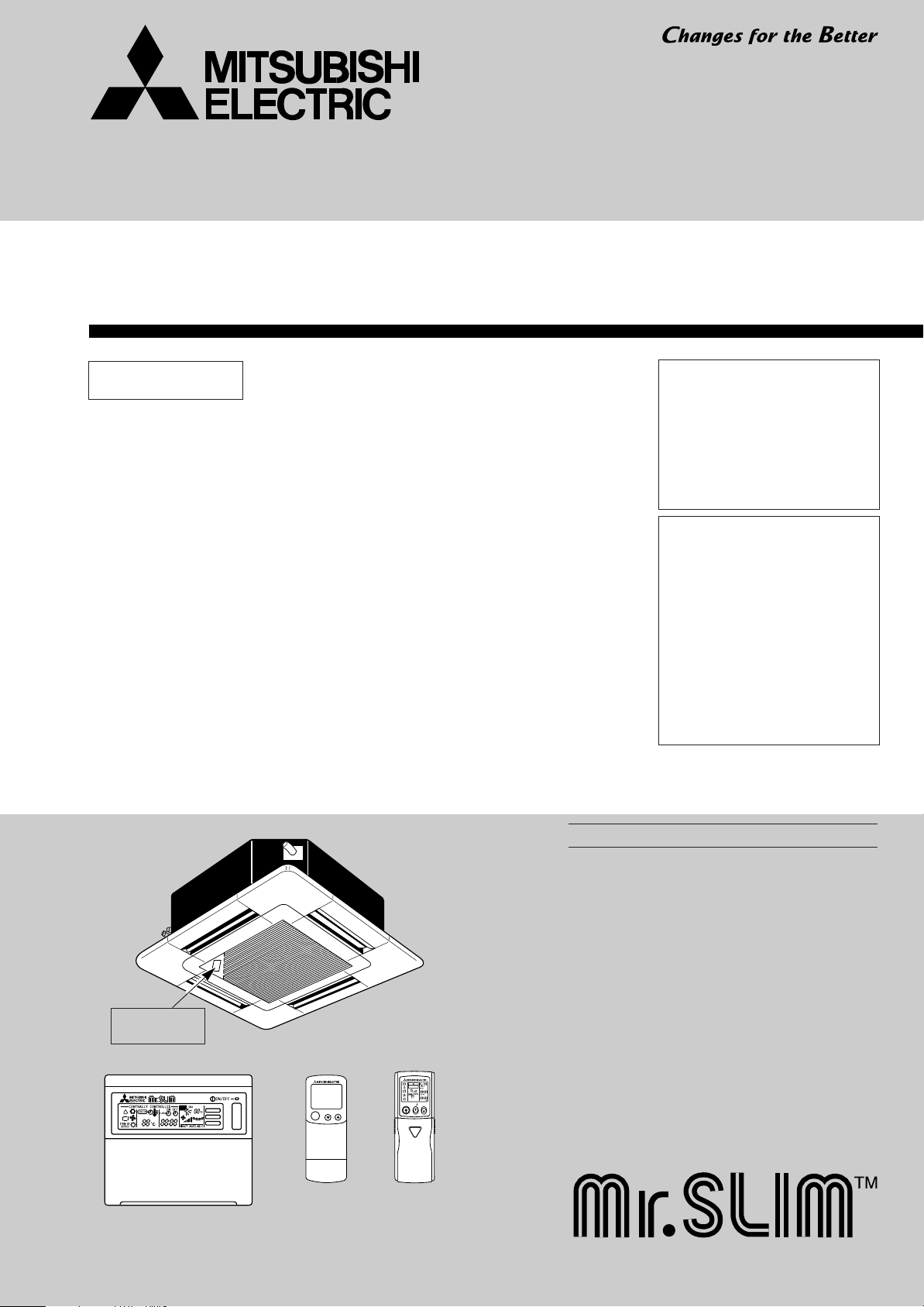
TECHNICAL & SERVICE MANUAL
FILTER
CHECK MODE
TEST RUN
SPLIT-TYPE, HEAT PUM PAIR CONDITIONERS
ON/OFF
ON/OFF TEMP
MODEL SELECT
NOT AVAILABLE
CHECK
TEST RUN
˚C
AMPM
AMPM
Revision:
Series PLH
Ceiling Cassettes
Indoor unit
[Model names] [Service Ref.]
PLH-3AK PLH-3AK.UK
PLH-3AK
PLH-3AKH PLH-3AKH.UK
PLH-3AKH
PLH-4AKS PLH-4AKS.UK
PLH-4AKS
PLH-4AKHS PLH-4AKHS.UK
PLH-4AKHS
PLH-5AKS PLH-5AKS.UK
PLH-5AKS
PLH-5AKHS PLH-5AKHS.UK
PLH-5AKHS
PLH-6AKS PLH-6AKS.UK
PLH-6AKS
PLH-6AKHS PLH-6AKHS.UK
PLH-6AKHS
1.UK
1.UK
1.UK
1.UK
1.UK
1.UK
1.UK
1.UK
• PLH-3AK
PLH-4AKS1.UK, PLH-4AKHS1.UK,
PLH-5AKS1.UK, PLH-5AKHS1.UK,
PLH-6AKS1.UK and
PLH-6AKHS1.UK are added in
REVISED EDITION-A.
• “14. PARTS LIST” has been
modified.
Note:
• This manual does not cover the
following outdoor units. When servicing them, please refer to the
following service manual and this
manual in a set.
[Service Ref.]
(OC150 REVISED EDITION-A)
PUH-3VKA2.UK PUH-3YKA2.UK
PUH-4YKSA2.UK
PUH-5YKSA2.UK
PUH-6YKSA2.UK
(OC184)
PUH-4VKSA.UK
• Please void OC211.
No. OC211
REVISED EDITION-A
1.UK, PLH-3AKH1.UK,
Model name
indication
WIRED REMOTE
CONTROLLER
INDOOR UNIT
PLH- •AK.UK PLH- •AK1.UK
PLH- •AKH.UK PLH- •AKH1.UK
PLH- •AKS.UK PLH- •AKS1.UK
PLH- •AKHS.UK PLH- •AKHS1.UK
WIRELESS REMOTE
CONTROLLER
CONTENTS
1. TECHNICAL CHANGES·······················2
2. PART NAMES AND FUNCTIONS········3
3. SPECIFICATIONS·································7
4. DATA ···················································11
5. OUTLINES AND DIMENSIONS··········24
6. WIRING DIAGRAM ·····························26
7.
REFRIGERANT SYSTEM DIAGRAM
8. OPERATION FLOW-CHART··············28
9. MICROPROCESSOR CONTROL·······32
10. TROUBLESHOOTING························54
11. 4-WAY AIR FLOW SYSTEM···············66
12. SYSTEM CONTROL···························72
13. DISASSEMBLY PROCEDURE···········77
14. PARTS LIST········································80
15. OPTIONAL PARTS·····························85
······27
Page 2
Revision:
Service Ref.
Page
IncorrectRevise point Correct
84
FUNCTIONAL PARTS
No.16
ROOM
TEMPERATURE
THERMISTOR
S70 E00 202S70 17J 202
PLH-5AKS.UK
PLH-5AKHS.UK
PLH-6AKS.UK
PLH-6AKHS.UK
PLH-3AK.UK
PLH-3AKH.UK
PLH-4AKS.UK
PLH-4AKHS.UK
PLH-5AKS.UK
PLH-5AKHS.UK
PLH-6AKS.UK
PLH-6AKHS.UK
Service Ref.
Page
Old
parts code
Revise point
New
part code
Old
part code
New
part code
83
84
FUNCTIONAL PARTS
No.4 CONTROLLER
BOARD
FUNCTIONAL PARTS
No.4 CONTROLLER
BOARD
S70 E01 310*
S70 E01 310
S70 E02 310
S70 E03 310
S70 E04 310
S70 E05 310
S70 E06 310
S70 E07 310
S70 E08 310
PLH-3AK.UK
PLH-3AKH.UK
PLH-4AKS.UK
PLH-4AKHS.UK
PLH-5AKS.UK
PLH-5AKHS.UK
PLH-6AKS.UK
PLH-6AKHS.UK
Service Ref.
Page
Revise point
83
84
FUNCTIONAL PARTS
No.7 DRAIN PUMP
FUNCTIONAL PARTS
No.7 DRAIN PUMP
S70 E02 355S70 E01 355
ON/OFF
CHECK
ADDRESS
UNIT No.
FUNCTION No.
SELECTION No.
AM
PM
AM
PM
TEST RUN
FUNCTION
˚C
TEMP.
1. “ 14. PARTS LIST ” has been modified on page 83 and 84.
Spare CONTROLLER BOARD are unified.
DRAIN PUMP has been changed.
2. The description “The part name of symbol “I.B” is “SPCB” ” is added on both pages of wiring diagram and part list.
1
TECHNICAL CHANGES
PLH-3AK.UK ➔ PLH-3AK1.UK
PLH-3AKH.UK ➔ PLH-3AKH1.UK
PLH-4AKS.UK ➔ PLH-4AKS1.UK
PLH-4AKHS.UK ➔ PLH-4AKHS
1.UK
PLH-5AKS.UK ➔ PLH-5AKS1.UK
PLH-5AKHS.UK ➔ PLH-5AKHS1.UK
PLH-6AKS.UK ➔ PLH-6AKS
PLH-6AKHS.UK ➔ PLH-6AKHS1.UK
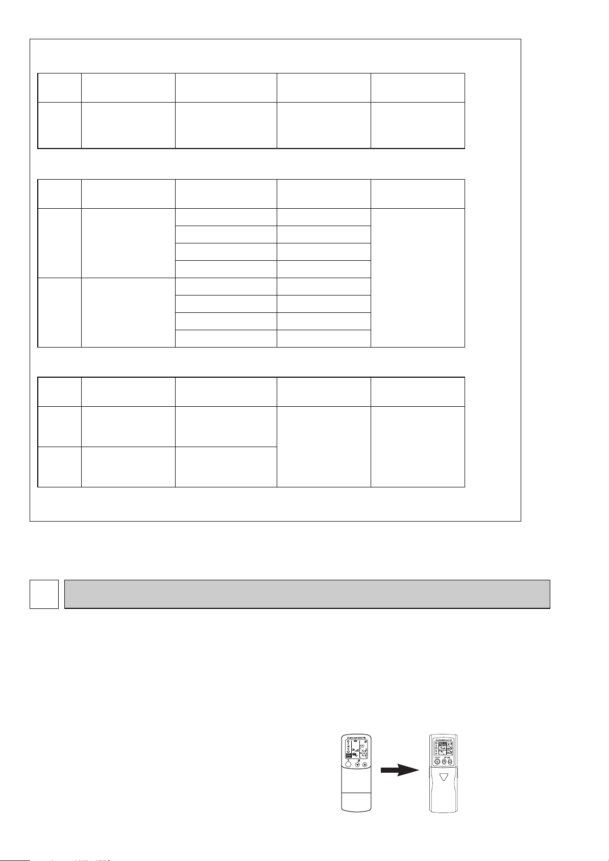
● WIRELESS REMOTE CONTROLLER has been changed.
(PAR-SL95K-E ➔ PAR-SL97A-E)
1.UK
2
Page 3
2
FILTER
CHECK MODE
TEST RUN
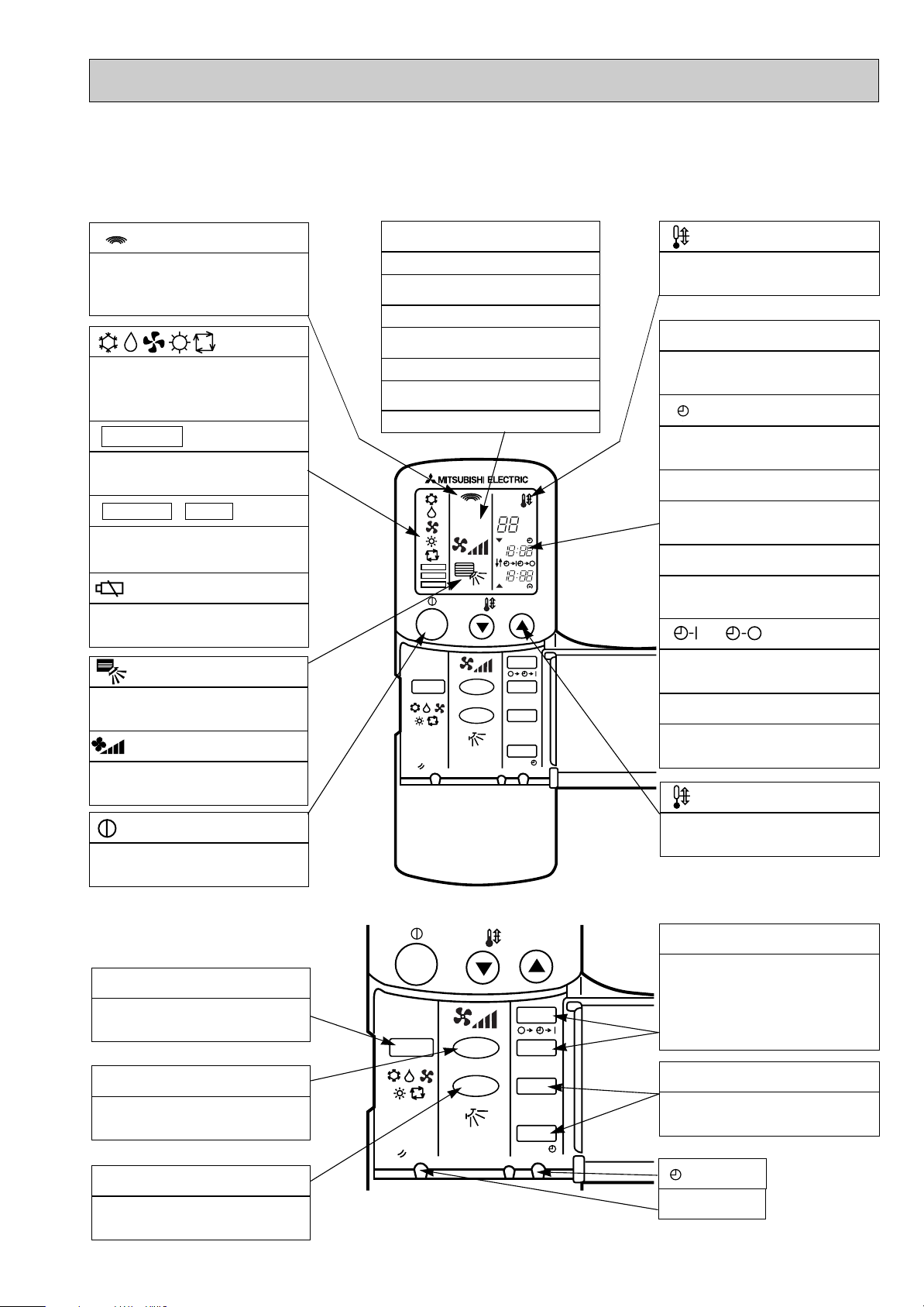
PART NAMES AND FUNCTIONS
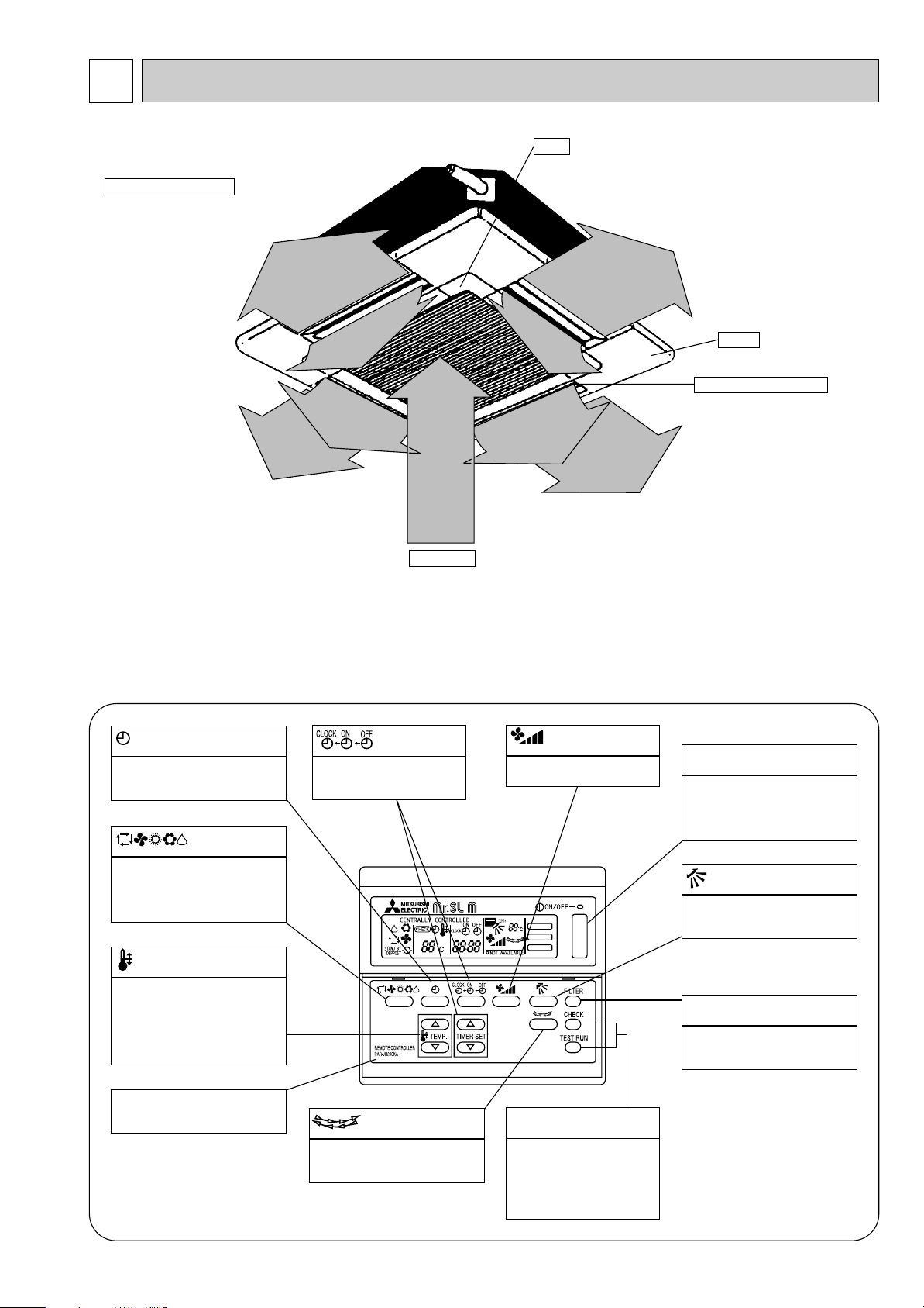
● Indoor Unit
Filter
Removes dust and pollutants
Horizontal Air Outlet
from intake air
Sets airflow of horizontal automatically
during cooling or dehumidifying.
Auto Air Swing Vane
Disperses airflow up and
down and adjusts the angle
of airflow direction.
Air Intake
Intakes air from room.
● Remote controller
On the controls are set, the same operation mode can be repeated by simply pressing the ON/OFF button.
Grille
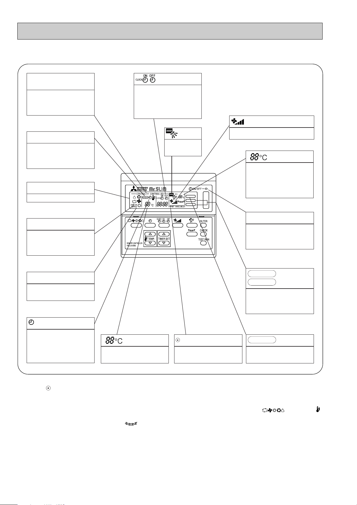
● Operation buttons
button
This switches between continuous
operation and the timer operation.
button
Press this button to switch the cooling,
electronic dry (dehumidify), automatic
and heating modes.
TEMP. button
This sets the room temperature, The
temperature setting can be performed
in 1°C units
Setting range
Cooling 19°C to 30°C
Heating 17°C to 28°C
This model name of the remote controller is indicated.
button
This sets the current time. start
time and stop time.
button
This switches the horizontal fan
motion ON and OFF.
(This button does not operate on this
model)
button
This sets the ventilation fan
speed.
CHECK-TEST RUN button
Only press this button to per-
form an inspection check or test
operation, Do not use it for normal operation.
ON/OFF button
This switches between the operation
and stop modes each time it is
pressed. The lamp on this button
lights during operation.
button
This adjusts the vertical angle of the
ventilation.
FILTER button
This resets the filter cleaning indica-
tion display.
3
Page 4
FILTER
CHECK MODE
TEST RUN
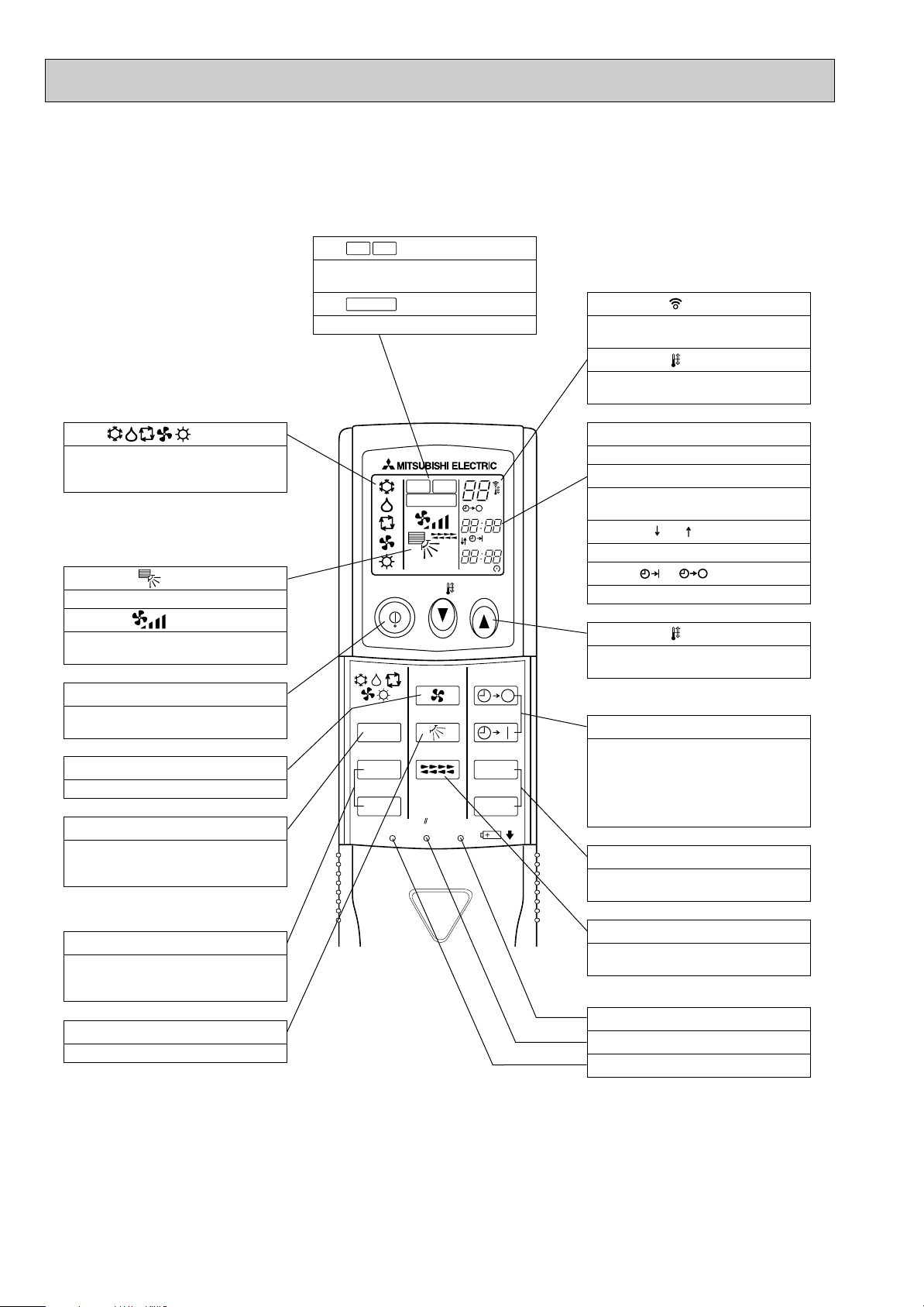
● Display
CENTRALLY
CONTROLLED display
This indicates when the unit is con-
trolled by optional features such as
central control type remote controller.
CHECK display
This indicates when a malfunction
has occurred in the unit which should
be checked.
OPERATION MODE display
This indicates the operation mode.
STANDBY display
The [STANDBY] symbol is only dis-
played from the time the heating
operation starts until the heated air
begins to blow.
display
The current time , start time and stop
time can be displayed in ten second
intervals by pressing the time setting
button. The start time or stop time is
always displayed during the timer
operation.
display
This displays the air
direction.
In this display example on the bottom left, a condition where all display lamps light is shown for explanation purposes although this differs
from actual operation.
display
The selected fan speed is displayed.
display
The temperature of the suction air is
displayed during operation. The display range is 10° to 35°C. The display flashes 10°C when the actual
temperature is less than 10° and
flashes 35°C when the actual temperature is greater than 35°C.
Operation lamp
This lamp lights during operation,
goes off when the unit stops and
flashes when a malfunction occurs.
DEFROST display
This indicates when the defrost oper-
ation is performed.
CHECK MODE
TEST RUN
This display lights in the check mode
or when a test operation is performed.
display
display
This indicates when the continuous
operation and time operation modes
are set.
It also display the time for the timer
operation at the same time as when
it is set.
display
This displays the selected setting
temperature.
display
This lamp lights when electricity is
supplied to the unit.
Caution
● Only the display lights when the unit is stopped and power supplied to the unit.
● When power is turned ON for the first time the (CENTRAL CTRL) display appears to go off momentarily but this is not a
malfunction.
● When the central control remote control unit, which is sold separately, is used the ON-OFF button, button and
TEMP. button do not operate.
● “NOT AVAILABLE” is displayed when the button are pressed.This indicates that this room unit is not equipped with
the fan direction adjustment function and the louver function.
FILTER
This lamp lights when the filter need
to be cleaned.
display
4
Page 5
PLH-3AK.UK PLH-4AKS.UK PLH-5AKS.UK PLH-6AKS.UK
PLH-3AKH.UK PLH-4AKHS.UK PLH-5AKHS.UK PLH-6AKHS.UK
● Wireless remote controller
● When cover is open.
display
Lights up while transmission to the indoor unit
is mode using switches.
display
OPERATION MODE display
Operation mode display indicates which operation mode is in effect.
• FUNCTION
Lights up when function are set.
display
• TEST RUN • CHECK display
CHECK&TEST RUN display indicates that the
unit is being checked or test-run.
display
Displays when batteries are dead.
display
The vertical direction of airflow is indicated.
display
FAN SPEED display indicates which fan
speed has been selected.
ADDRESS display
Displays the refrigerant address.
UNIT NO. display
Displays the number of unit..
FUNCTION NO. display
Displays the mode.
SELECTION NO. display
Displays the selection number..
ADDRESS
UNIT No.
FUNCTION No.
SELECTION No.
FUNCTION
TEST RUN
CHECK
ON/OFF
MODE FAN
RESET
VANE
AM
PM
AM
PM
TEMP.
˚C
START
STOP
HR.
MIN.
display
SET TEMP. display indicates desired temperature set.
CLOCK display
DIsplays the current time.
“ ”display
Flashes when the current time is displayed.
TIMER display
Displays when in timer operation or when setting timer.
➡
“ ” “ ” display
➡
Displays the order of timer operation.
“ ” “ ” display
Displays whether timer is on or off.
▼
“ ” “ ” display
Displays when the current time and the timer
time can be changed.
▼
TEMP. button
display
The unit is turned ON and OFF alternately
each time the button is pressed.
● When cover is open.
MODE SELECT button
Used to switch the operation mode between
cooling , drying , blowing , heating and auto
mode.
FAN SPEED SELECT button
Used to change the fan speed.
VANE CONTROL button
Used to change the airflow direction.
ON/OFF
MODE FAN
RESET
5
VANE
TEMP.
START
STOP
HR.
MIN.
SET TEMPERATURE button sets any desired
room temperature.
TIMER CONTROL buttons
STOP (OFF timer): when this switch is set,
the air conditioner will be automatically
stopped at the preset time.
START(ON timer): when this switch is set, the
air conditioner will be automatically started at
the preset time.
HR. and MIN.buttons
Buttons used to set the “hour and minute” of
the current time and timer settings.
button
RESET button
Page 6
PLH-3AK1.UK PLH-4AKS1.UK PLH-5AKS1.UK PLH-6AKS1.UK
ON/OFF TEMP
FAN
VANE
TEST RUN
AUTO STOP
AUTO START
h
min
LOUVER
MODE
CHECK
RESETSET CLOCK
MODEL SELECT
NOT AVAILABLE
CHECK
TEST RUN
˚C
AMPM
AMPM
VANE CONTROL button
Used to change the air flow direction.
CLOCK button
RESET button
SET button
ON/OFF button
The unit is turned ON and OFF alternately
each time the button is pressed.
LOUVER button
This switch the horizontal fan motion ON
and OFF.
(Not available for this model.)
MODE SELECT button
Used to switch the operation mode between
cooling, drying, heating and auto mode.
CHECK-TEST RUN button
Only press this button to perform an inspection check or test operation.
Do not use it for normal operation.
FAN SPEED SELECT button
Used to change the fan speed.
TIMER display
Displays when in timer operation or when
setting timer.
button
SET TEMPERATURE button sets any desired
room temperature.
CLOCK display
Displays the current time.
“ ” “ ” display
Displays the order of timer operation.
“ ” “ ” display
Displays whether timer is on or off.
Buttons used to set the “hour and minute” of
the current time and timer settings.
h and min buttons
display
SET TEMP. display indicates desired temperature set.
display
FAN SPEED display indicates which fan
speed has been selected.
display
The vertical direction of air flow is indicated.
display
Blinks when model is selected.
display
Lights up while transmission to the indoor
unit is mode using switches.
display
CHECK&TEST RUN display indicates that
the unit is being checked or test-run.
display
OPERATION MODE display
Operation mode display indicates which operation mode is in effect.
TIMER CONTROL buttons
AUTO STOP (OFF timer): when this switch
is set, the air conditioner will be automatically stopped at the preset time.
AUTO START (ON timer): when this switch
is set, the air conditioner will be automatically started at the preset time.
MODEL SELECT
CHECK
TEST RUN
PLH-3AKH1.UK PLH-4AKHS1.UK PLH-5AKHS1.UK PLH-6AKHS1.UK
●Wireless remote controller
● When cover is open.
6
Page 7
3
Cooling
26,300
7,700
3.32
0.17
0.81
1.00
UNIT : 840(33-1/6)
UNIT : 840(33-1/6)
UNIT : 258(10-1/8)
UNIT : 24(53) [26(57)]
3.15
13.82/5.16
58/37
Heating
28,700[35,800]
8,400[10,500]
3.11[5.21]
0.17[2.27]
0.81[9.47]
1.00[9.7]
PANEL : 950(37-3/8)
PANEL : 950(37-3/8)
PANEL : 30(1-3/16)
PANEL : 5(11)
2.94
12.89/4.81
58/37
Single, 50Hz, 220-240V
Grille : Munsell 0.70Y 8.59/0.97
Plate fin coil
Turbo fan (direct) x 1
0.07
15-20(530-705)
0(direct blow)
[2.1]
Remote controller & built-in
28-34
32(1-1/4)
PUH-3VKA
2.UK / PUH-3YKA2.UK
Single, 50Hz, 220-240V/3, 50Hz, 380-415V(4wires)
Munsell 5Y 7/1
Capillary tube
Hermetic
NH52VNDT / NH52YDAT
2.2/2.4
Line start
w1
Plate fin coil
Propeller (direct) x1
0.085
50(1764)
Reverse cycle
52
870(34-1/4)
295+24 (11-5/8 add 1)
850(33-1/4)
75(165)
R-22
3.2(7.1)
1.6<MS-32>
9.52 (3/8)
15.88(5/8)
Flared
Flared
Max. 50m
Max. 50m
Service Ref.
Power supply(phase, cycle, voltage)
External finish
Heat exchanger
Fan
Booster heater
Operation control & Thermostat
Noise level(Low-High)
Unit drain pipe O.D.
Dimensions
Weight
Service Ref.
Power supply (phase, cycle, voltage)
External finish
Refrigerant control
Compressor
Heat exchanger
Fan
Defrost method
Noise level
Dimensions
Weight
Refrigerant
Pipe size O.D.
Connection method
Between the indoor & outdoor units
Input
Running current
Starting current
Fan(drive) x No.
Fan motor output
Airflow(Low-High)
External static pressure
Input
Running current
Starting current
Model
Motor output
Starter type
Protection devices
Fan(drive) x No.
Fan motor output
Airflow
Charge
Oil<Model>
W
D
H
W
D
H
Liquid
Gas
Indoor side
Outdoor side
Height difference
Piping length
Function
Capacity
Total input
INDOOR UNITOUTDOOR UNIT
REFRIGERANT
PIPING
Item
Service Ref.
Btu/h
W
kW
kW
A
A
kW
K/ min (CFM)
Pa
kW
dB
mm(in.)
mm(in.)
mm(in.)
mm(in.)
kg(lbs)
kW
A
A
kW
kW
K/ min (CFM)
dB
mm(in.)
mm(in.)
mm(in.)
kg(lbs)
kg(lbs)
L
mm(in.)
mm(in.)
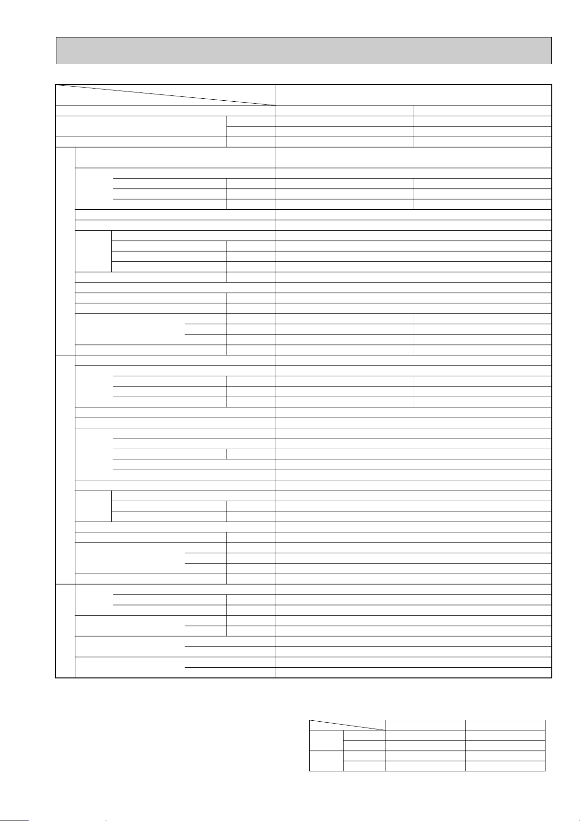
PLH-3AK.UK PLH-3AK
1.UK
PLH-3AKH.UK PLH-3AKH1.UK
PLH-3AK.UK PLH-3AK
1.UK
PLH-3AKH.UK PLH-3AKH1.UK
Guaranteed operating range
Upper limit
Lower limit
Upper limit
Lower limit
Indoor
Outdoor
Cooling
Heating
D.B. 35˚C, W.B. 22.5˚C
D.B. 21˚C, W.B. 15.5˚C
D.B. 27°C
D.B. 20°C
D.B. 46˚C
D.B. -5˚C
D.B. 21˚C, W.B. 15.5˚C
D.B. -8.5˚C, W.B. -9.5˚C
SPECIFICATIONS
w1 V …Internal Thermostat, HP switch
Y…Anti-phase protector, thermal relay, thermal switch, HP switch
Notes: Rating condition (ISO T1<JIS B8616>)
Cooling: Indoor : D.B. 27°C, W.B. 19°C
Heating: Indoor : D.B. 20°C
Refrigerant piping length(one way):5m(16ft)
Outdoor : D.B. 35°C, W.B. 24°C
Outdoor : D.B. 7°C, W.B. 6°C
7
Page 8
Cooling
33,100
9,700
3.46
0.26
1.25
2.0
UNIT : 840(33-1/6)
UNIT : 840(33-1/6)
UNIT : 298(11-3/4)
UNIT : 30(66)[32(71)]
3.52 / 3.20
16.30 / 5.24
79 / 40
Heating
35,500[44,400]
10,400[13,000]
3.45[6.05]
0.26[2.86]
1.25[11.93]
2.0[12.7]
PANEL : 950(37-3/8)
PANEL : 950(37-3/8)
PANEL : 30(1-3/16)
PANEL : 5(11)
3.52 / 3.19
16.30 / 5.22
79 / 40
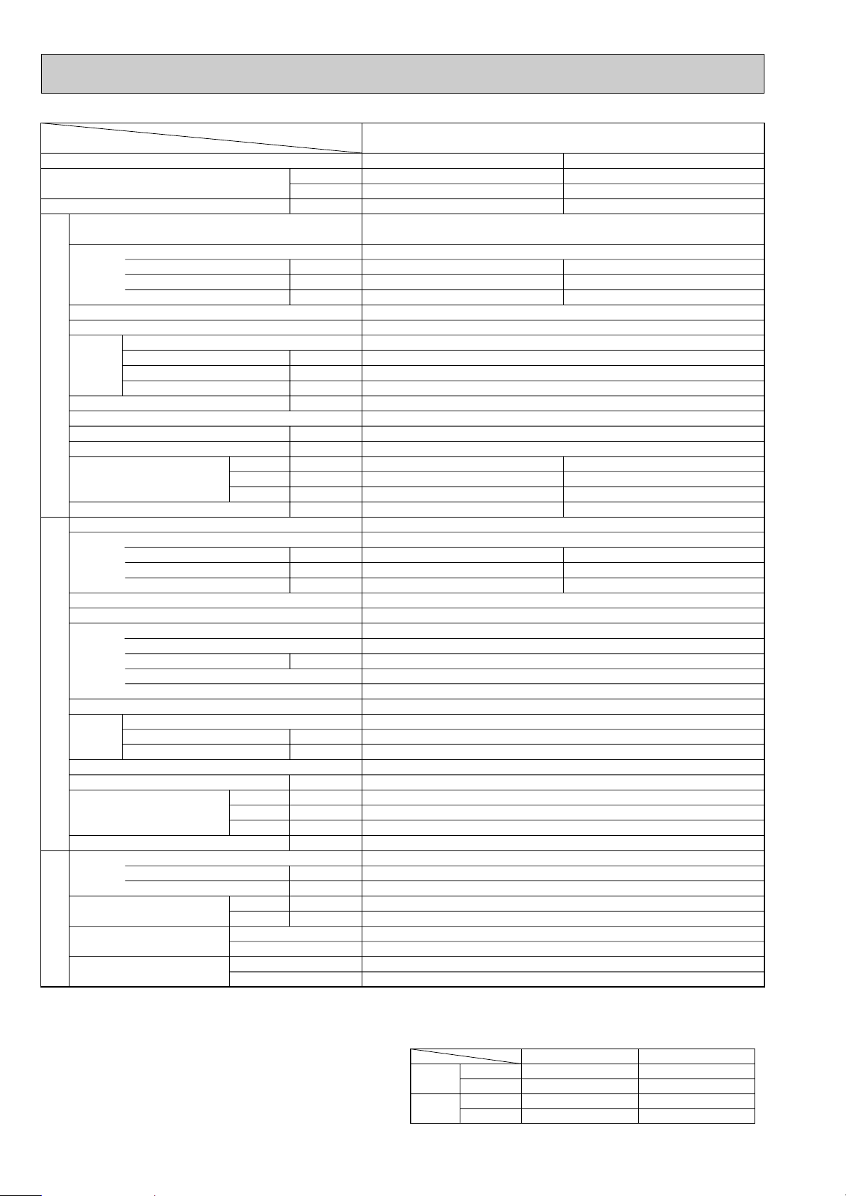
Service Ref.
Power supply(phase, cycle,voltage)
External finish
Heat exchanger
Fan
Booster heater
Operation control & Thermostat
Noise level(Low-High)
Unit drain pipe O.D.
Dimensions
Weight
Service Ref.
Power supply (phase, cycle, voltage)
External finish
Refrigerant control
Compressor
Heat exchanger
Fan
Defrost method
Noise level
Dimensions
Weight
Refrigerant
Pipe size O.D.
Connection method
Between the indoor & outdoor units
Input
Running current
Starting current
Fan(drive) x No.
Fan motor output
Airflow(Low-High)
External static pressure
Input
Running current
Starting current
Model
Motor output
Starter type
Protection devices
Fan(drive) x No.
Fan motor output
Airflow
Charge
Oil<Model>
W
D
H
W
D
H
Liquid
Gas
Indoor side
Outdoor side
Height difference
Piping length
Function
Capacity
Total input
INDOOR UNITOUTDOOR UNIT
REFRIGERANT
PIPING
Item
Service Ref.
Single, 50Hz, 220-240V
Grille : Munsell 0.70Y 8.59/0.97
Plate fin coil
Turbo fan (direct) x 1
0.120
20-28(705-990)
0(direct blow)
[2.6]
Remote controller & built-in
33-41
32(1-1/4)
PUH-4VKSA.UK / PUH-4YKSA
2.UK
Single 50Hz 220V-240V / 3, 50Hz, 380V-415V(4wire)
Munsell 5Y 7/1
Capillary tube
Hermetic
NH56VNDT / NH56YDAT
2.7
Line start
Internal thermostat, HP switch / Anti-phase protector, Thermal relay, Thermal switch, HP switch
Plate fin coil
Propeller (direct) x2
0.065+0.065
95(3550)
Reverse cycle
54
870(34-1/4)
295+24(11-5/8 add 1)
1258(49-1/2)
94(207)
R-22
4.2(9.2)
1.6<MS-32>
9.52(3/8)
19.05(3/4)
Flared
Flared
Max. 50m
Max. 50m
Btu/h
W
kW
kW
A
A
kW
K/ min (CFM)
Pa
kW
dB
mm(in.)
mm(in.)
mm(in.)
mm(in.)
kg(lbs)
kW
A
A
kW
kW
K/ min (CFM)
dB
mm(in.)
mm(in.)
mm(in.)
kg(lbs)
kg(lbs)
L
mm(in.)
mm(in.)
PLH-4AKS.UK PLH-4AKS
1.UK
PLH-4AKHS.UK PLH-4AKHS1.UK
PLH-4AKS.UK PLH-4AKS
1.UK
PLH-4AKHS.UK PLH-4AKHS1.UK
Guaranteed operating range
Upper limit
Lower limit
Upper limit
Lower limit
Indoor
Outdoor
Cooling
Heating
D.B. 35˚C, W.B. 22.5˚C
D.B. 21˚C, W.B. 15.5˚C
D.B. 27°C
D.B. 20°C
D.B. 46˚C
D.B. -5˚C
D.B. 21˚C, W.B. 15.5˚C
D.B. -8.5˚C, W.B. -9.5˚C
Notes: Rating condition (ISO T1<JIS B8616>)
Cooling: Indoor : D.B. 27°C, W.B. 19°C
Outdoor : D.B. 35°C, W.B. 24°C
Heating: Indoor : D.B. 20°C
Outdoor : D.B. 7°C, W.B. 6°C
Refrigerant piping length(one way):5m(16ft)
8
Page 9
Item
Guaranteed operating range
Upper limit
Lower limit
Upper limit
Lower limit
Indoor
Outdoor
Cooling
Heating
D.B. 35˚C, W.B. 22.5˚C
D.B. 21˚C, W.B. 15.5˚C
D.B. 27°C
D.B. 20°C
D.B. 46˚C
D.B. -5˚C
D.B. 21˚C, W.B. 15.5˚C
D.B. -8.5˚C, W.B. -9.5˚C
Service Ref.
Function
Capacity
Total input
Service Ref.
Power supply(phase, cycle,voltage)
Input
Running current
Starting current
External finish
Heat exchanger
Fan
Fan(drive) x No.
Fan motor output
Airflow(Low-High)
K/ min (CFM)
External static pressure
INDOOR UNITOUTDOOR UNIT
Booster heater
Operation control & Thermostat
Noise level(Low-High)
Unit drain pipe O.D.
W
Dimensions
D
H
Weight
Service Ref.
Power supply (phase, cycle, voltage)
Input
Running current
Starting current
External finish
Refrigerant control
Compressor
Model
Motor output
Starter type
Protection devices
Heat exchanger
Fan
Fan(drive) x No.
Fan motor output
Airflow
K/ min (CFM)
Defrost method
Noise level
W
Dimensions
D
H
Weight
Refrigerant
Charge
Oil<Model>
Pipe size O.D.
PIPING
Connection method
REFRIGERANT
Between the indoor & outdoor units
Liquid
Gas
Indoor side
Outdoor side
Height difference
Piping length
Notes: Rating condition (ISO T1<JIS B8616>)
Cooling: Indoor : D.B. 27°C, W.B. 19°C
Outdoor : D.B. 35°C, W.B. 24°C
Heating: Indoor : D.B. 20°C
Outdoor : D.B. 7°C, W.B. 6°C
Refrigerant piping length(one way):5m(16ft)
Btu/h
W
kW
kW
A
A
kW
Pa
kW
dB
mm(in.)
mm(in.)
mm(in.)
mm(in.)
kg(lbs)
kW
A
A
kW
kW
dB
mm(in.)
mm(in.)
mm(in.)
kg(lbs)
kg(lbs)
L
mm(in.)
mm(in.)
PLH-5AKS.UK PLH-5AKS
1.UK
PLH-5AKHS.UK PLH-5AKHS1.UK
Cooling
42,300
12,400
4.51
PLH-5AKS.UK PLH-5AKS
Heating
47,800[58,000]
14,000[17,000]
4.46[7.46]
1.UK
PLH-5AKHS.UK PLH-5AKHS1.UK
Single, 50Hz, 220-240V
0.30
1.43
2.0
0.30[3.30]
1.43[13.77]
2.0[14.3]
Grille : Munsell 0.70Y 8.59/0.97
Plate fin coil
Turbo fan (direct) x 1
0.120
22-30(775-1,060)
0(direct blow)
[3.0]
Remote controller & built-in
35-43
32(1-1/4)
UNIT : 840(33-1/16)
UNIT : 840(33-1/16)
UNIT : 298(11-3/4)
UNIT : 30(66) [32(71)]
PUH-5YKSA
PANEL : 950(37-3/8)
PANEL : 950(37-3/8)
PANEL : 30(1-3/16)
PANEL : 5(11)
2.UK
3, 50Hz, 380-415V(4wire)
4.21
6.89
65
4.16
6.81
65
Munsell 5Y 7/1
Capillary tube
Hermetic
ZR61KC-TFD
3.5
Line start
Internal thermostat, Anti-phase protector, Thermal switch, HP switch
Plate fin coil
Propeller (direct) x2
0.085+0.085
95(3550)
Reverse cycle
55
970(38-3/16)
345+24(13-9/16 add 1)
1258(49-1/2)
114(251)
R-22
5.4(11.9)
2.13<SONTEX-200LT>
9.52(3/8)
19.05(3/4)
Flared
Flared
Max. 50m
Max. 50m
9
Page 10
Cooling
47,800
14,000
5.07
0.34
1.64
2.0
UNIT : 840(33-1/16)
UNIT : 840(33-1/16)
UNIT : 298(11-3/4)
UNIT : 32(71)[34(75)]
4.73
7.74
74
Heating
54,900[65,200]
16,100[19,100]
4.92[7.92]
0.34[3.34]
1.64[13.94]
2.0[14.3]
PANEL : 950(37-3/8)
PANEL : 950(37-3/8)
PANEL : 30(1-3/16)
PANEL : 5(11)
4.58
7.50
74
Service Ref.
Power supply(phase, cycle, voltage)
External finish
Heat exchanger
Fan
Booster heater
Operation control & Thermostat
Noise level(Low-High)
Unit drain pipe O.D.
Dimensions
Weight
Service Ref.
Power supply (phase, cycle, voltage)
External finish
Refrigerant control
Compressor
Heat exchanger
Fan
Defrost method
Noise level
Dimensions
Weight
Refrigerant
Pipe size O.D.
Connection method
Between the indoor &
outdoor units
Input
Running current
Starting current
Fan(drive) x No.
Fan motor output
Airflow(Low-High)
External static pressure
Input
Running current
Starting current
Model
Motor output
Starter type
Protection devices
Fan(drive) x No.
Fan motor output
Airflow
Charge
Oil<Model>
W
D
H
W
D
H
Liquid
Gas
Indoor side
Outdoor side
Height difference
Piping length
Function
Capacity
Total input
INDOOR UNITOUTDOOR UNIT
REFRIGERANT
PIPING
Item
Service Ref.
Single, 50Hz, 220-240V
Grille : Munsell 0.70Y 8.59/0.97
Plate fin coil
Turbo fan (direct) x 1
0.120
22-30(775-1,060)
0(direct blow)
[3.0]
Remote controller & built-in
37-45
32(1-1/4)
PUH-6YKSA
2.UK
3, 50Hz, 380-415V(4wire)
Munsell 5Y 7/1
Capillary tube
Hermetic
ZR68KC-TFD
4.0
Line start
Internal thermostat, Anti-phase protector, Thermal switch, HP switch
Plate fin coil
Propeller (direct) x2
0.10+0.10
100(3530)
Reverse cycle
56
970(38-3/16)
345+24(13-9/16 add 1)
1258(49-1/2)
117(258)
R-22
5.0(11.0)
1.774<SONTEX-200LT>
9.52(3/8)
19.05(3/4)
Flared
Flared
Max. 50m
Max. 50m
Btu/h
W
kW
kW
A
A
kW
K/ min (CFM)
Pa
kW
dB
mm(in.)
mm(in.)
mm(in.)
mm(in.)
kg(lbs)
kW
A
A
kW
kW
K/ min (CFM)
dB
mm(in.)
mm(in.)
mm(in.)
kg(lbs)
kg(lbs)
L
mm(in.)
mm(in.)
PLH-6AKS.UK PLH-6AKS
1.UK
PLH-6AKHS.UK PLH-6AKHS1.UK
PLH-6AKS.UK PLH-6AKS
1.UK
PLH-6AKHS.UK PLH-6AKHS1.UK
Guaranteed operating range
Upper limit
Lower limit
Upper limit
Lower limit
Indoor
Outdoor
Cooling
Heating
D.B. 35˚C, W.B. 22.5˚C
D.B. 21˚C, W.B. 15.5˚C
D.B. 27°C
D.B. 20°C
D.B. 46˚C
D.B. -5˚C
D.B. 21˚C, W.B. 15.5˚C
D.B. -8.5˚C, W.B. -9.5˚C
Notes: Rating condition (ISO T1<JIS B8616>)
Cooling: Indoor : D.B. 27°C, W.B. 19°C
Outdoor : D.B. 35°C, W.B. 24°C
Heating: Indoor : D.B. 20°C
Refrigerant piping length(one way):5m(16ft)
Outdoor : D.B. 7°C, W.B. 6°C
10
Page 11

4
Outdoor intake air D.B.(°C)
20 25 30
Indoor
Intake air
D.B.(°C)
Indoor
Intake air
W.B.(°C)
20
20
22
22
22
24
24
24
24
26
26
26
26
27
27
27
27
28
28
28
28
30
30
30
30
32
32
32
32
16
18
16
18
20
16
18
20
22
16
18
20
22
16
18
20
22
16
18
20
22
16
18
20
22
16
18
20
22
7768
8271
7768
8271
8779
7768
8271
8779
9293
7768
8271
8779
9293
7768
8271
8779
9293
7768
8271
8779
9293
7768
8271
8779
9293
7768
8271
8779
9293
CA SHC SHF P.C. CA SHC SHF P.C. CA SHC SHF P.C.
4972
4301
5593
4963
4214
6214
5624
4916
4089
6836
6286
5619
4832
7147
6617
5970
5204
7457
6948
6321
5576
7768
7609
7023
6319
7768
8271
7726
7063
0.64
0.52
0.72
0.60
0.48
0.80
0.68
0.56
0.44
0.88
0.76
0.64
0.52
0.92
0.80
0.68
0.56
0.96
0.84
0.72
0.60
1.00
0.92
0.80
0.68
1.00
1.00
0.88
0.76
0.64
0.52
0.72
0.60
0.48
0.80
0.68
0.56
0.44
0.88
0.76
0.64
0.52
0.92
0.80
0.68
0.56
0.96
0.84
0.72
0.60
1.00
0.92
0.80
0.68
1.00
1.00
0.88
0.76
0.64
0.52
0.72
0.60
0.48
0.80
0.68
0.56
0.44
0.88
0.76
0.64
0.52
0.92
0.80
0.64
0.52
0.96
0.84
0.72
0.60
1.00
0.92
0.80
0.68
1.00
1.00
0.88
0.76
2.66
2.71
2.66
2.71
2.77
2.66
2.71
2.77
2.82
2.66
2.71
2.77
2.82
2.66
2.71
2.77
2.82
2.66
2.71
2.77
2.82
2.66
2.71
2.77
2.82
2.66
2.71
2.77
2.82
7555
8053
7555
8053
8573
7555
8053
8573
9115
7555
8053
8573
9115
7555
8053
8573
9115
7555
8053
8573
9115
7555
8053
8573
9115
7555
8053
8573
9115
4835
4188
5440
4832
4115
6044
5476
4801
4011
6649
6120
5487
4740
6951
6443
5830
5104
7253
6765
6173
5469
7555
7409
6858
6198
7555
8053
7544
6927
2.77
2.83
2.77
2.83
2.89
2.77
2.83
2.89
2.94
2.77
2.83
2.89
2.94
2.77
2.83
2.89
2.94
2.77
2.83
2.89
2.94
2.77
2.83
2.89
2.94
2.77
2.83
2.89
2.94
7278
7760
7278
7760
8267
7278
7760
8267
8799
7278
7760
8267
8799
7278
7760
8267
8799
7278
7760
8267
8799
7278
7760
8267
8799
7278
7760
8267
8799
4658
4035
5240
4656
3968
5822
5277
4630
3872
6404
5898
5291
4576
6696
6208
5622
4928
6987
6518
5952
5279
7278
7139
6614
5983
7278
7760
7275
6687
2.99
3.06
2.99
3.06
3.12
2.99
3.06
3.12
3.19
2.99
3.06
3.12
3.19
2.99
3.06
3.12
3.19
2.99
3.06
3.12
3.19
2.99
3.06
3.12
3.19
2.99
3.06
3.12
3.19
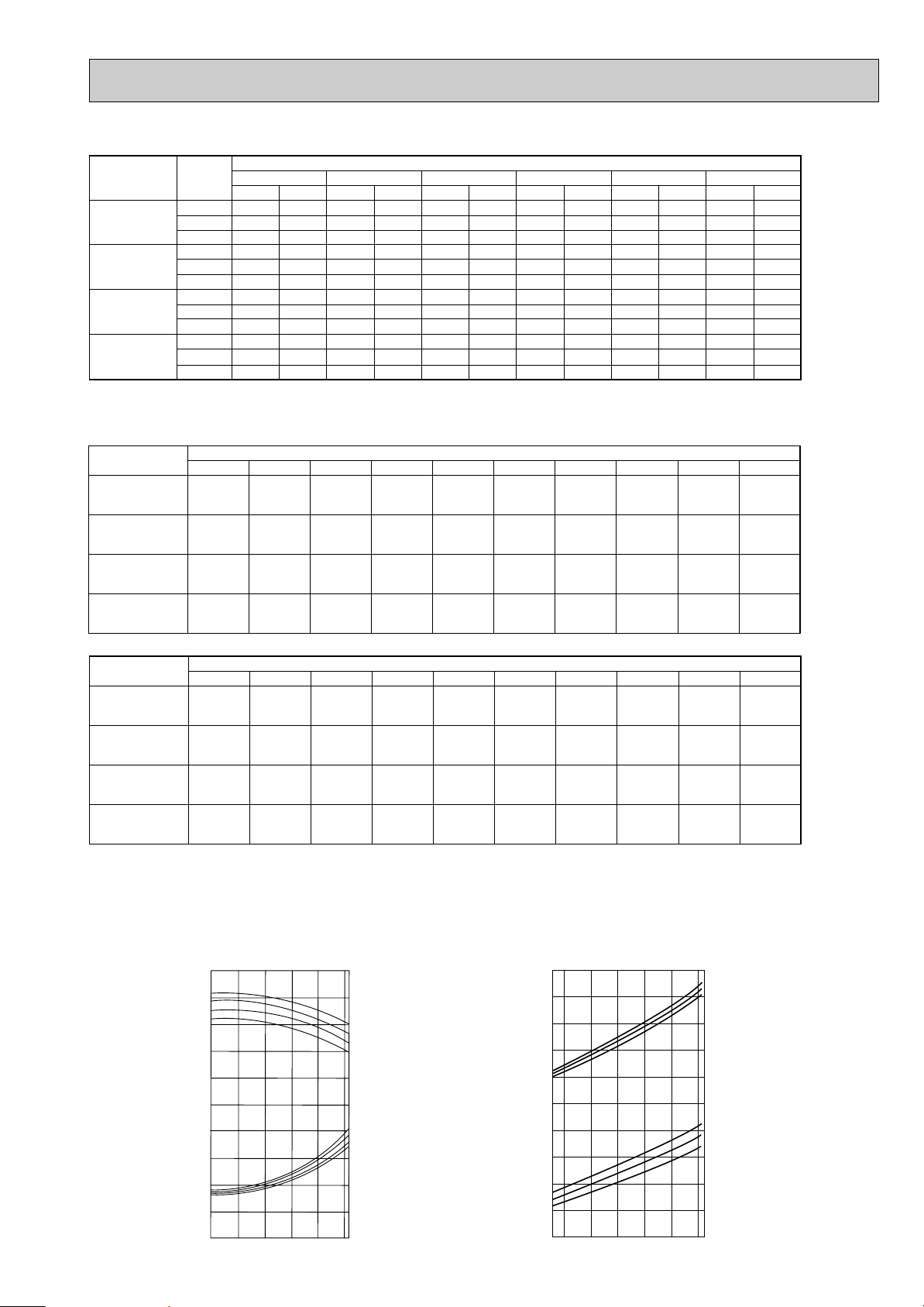
DATA
1. PERFORMANCE DATA [50Hz]
1) COOLING CAPACITY(1)
PLH-3AK.UK PLH-3AK1.UK
PLH-3AKH.UK PLH-3AKH1.UK
CA : Capacity (W) SHC : Sensible heat capacity (W)
P.C. : Power consumption (kW) SHF : Sensible heat factor
11
Page 12

COOLING CAPACITY(2)
Outdoor intake air D.B.(°C)
35 40 45
Indoor
Intake air
D.B.(°C)
Indoor
Intake air
W.B.(°C)
20
20
22
22
22
24
24
24
24
26
26
26
26
27
27
27
27
28
28
28
28
30
30
30
30
32
32
32
32
16
18
16
18
20
16
18
20
22
16
18
20
22
16
18
20
22
16
18
20
22
16
18
20
22
16
18
20
22
6983
7452
6983
7452
7948
6983
7452
7948
8470
6983
7452
7948
8470
6983
7452
7948
8470
6983
7452
7948
8470
6983
7452
7948
8470
6983
7452
7948
8470
CA SHC SHF P.C. CA SHC SHF P.C. CA SHC SHF P.C.
4469
3875
5028
4471
3815
5586
5067
4451
3727
6145
5664
5087
4405
6424
5962
5405
4743
6704
6260
5722
5082
6983
6856
6358
5760
6983
7452
6994
6437
0.64
0.52
0.72
0.60
0.48
0.80
0.68
0.56
0.44
0.88
0.76
0.64
0.52
0.92
0.80
0.68
0.56
0.96
0.84
0.72
0.60
1.00
0.92
0.80
0.68
1.00
1.00
0.88
0.76
0.64
0.52
0.72
0.60
0.48
0.80
0.68
0.56
0.44
0.88
0.76
0.64
0.52
0.92
0.80
0.68
0.56
0.96
0.84
0.72
0.60
1.00
0.92
0.80
0.68
1.00
1.00
0.88
0.76
0.64
0.52
0.72
0.60
0.48
0.80
0.68
0.56
0.44
0.88
0.76
0.64
0.52
0.92
0.80
0.64
0.52
0.96
0.84
0.72
0.60
1.00
0.92
0.80
0.68
1.00
1.00
0.88
0.76
3.20
3.28
3.20
3.28
3.36
3.20
3.28
3.36
3.44
3.20
3.28
3.36
3.44
3.20
3.28
3.36
3.44
3.20
3.28
3.36
3.44
3.20
3.28
3.36
3.44
3.20
3.28
3.36
3.44
6671
7130
6671
7130
7616
6671
7130
7616
8128
6671
7130
7616
8128
6671
7130
7616
8128
6671
7130
7616
8128
6671
7130
7616
8128
6671
7130
7616
8128
4269
3708
4803
4278
3656
5337
4848
4265
3576
5870
5419
4874
4227
6137
5704
5179
4552
6404
5989
5483
4877
6671
6559
6093
5527
6671
7130
6702
6178
3.42
3.51
3.42
3.51
3.60
3.42
3.51
3.60
3.70
3.42
3.51
3.60
3.70
3.42
3.51
3.60
3.70
3.42
3.51
3.60
3.70
3.42
3.51
3.60
3.70
3.42
3.51
3.60
3.70
6342
6793
6342
6793
7270
6342
6793
7270
7773
6342
6793
7270
7773
6342
6793
7270
7773
6342
6793
7270
7773
6342
6793
7270
7773
6342
6793
7270
7773
4059
3532
4566
4076
3490
5073
4619
4071
3420
5581
5163
4653
4042
5834
5434
4944
4353
6088
5706
5235
4664
6342
6250
5816
5286
6342
6793
6398
5908
3.64
3.73
3.64
3.73
3.84
3.64
3.73
3.84
3.97
3.64
3.73
3.84
3.97
3.64
3.73
3.84
3.97
3.64
3.73
3.84
3.97
3.64
3.73
3.84
3.97
3.64
3.73
3.84
3.97
PLH-3AK.UK PLH-3AK1.UK
PLH-3AKH.UK PLH-3AKH1.UK
CA : Capacity (W) SHC : Sensible heat capacity (W)
P.C. : Power consumption (kW) SHF : Sensible heat factor
12
Page 13

COOLING CAPACITY(3)
Outdoor intake air D.B.(°C)
20 25 30
Indoor
Intake air
D.B.(°C)
Indoor
Intake air
W.B.(°C)
20
20
22
22
22
24
24
24
24
26
26
26
26
27
27
27
27
28
28
28
28
30
30
30
30
32
32
32
32
16
18
16
18
20
16
18
20
22
16
18
20
22
16
18
20
22
16
18
20
22
16
18
20
22
16
18
20
22
9786
10419
9786
10419
11060
9786
10419
11060
11707
9786
10419
11060
11707
9786
10419
11060
11707
9786
10419
11060
11707
9786
10419
11060
11707
9786
10419
11060
11707
CA SHC SHF P.C. CA SHC SHF P.C. CA SHC SHF P.C.
6752
5939
7535
6773
5862
8318
7606
6746
5736
9101
8440
7631
6673
9492
8856
8073
7141
9786
9273
8516
7609
9786
10107
9401
8546
9786
10419
10285
9483
0.69
0.57
0.77
0.65
0.53
0.85
0.73
0.61
0.49
0.93
0.81
0.69
0.57
0.97
0.85
0.73
0.61
1.00
0.89
0.77
0.65
1.00
0.97
0.85
0.73
1.00
1.00
0.93
0.81
0.69
0.57
0.77
0.65
0.53
0.85
0.73
0.61
0.49
0.93
0.81
0.69
0.57
0.97
0.85
0.73
0.61
1.00
0.89
0.77
0.65
1.00
0.97
0.85
0.73
1.00
1.00
0.93
0.81
0.69
0.57
0.77
0.65
0.53
0.85
0.73
0.61
0.49
0.93
0.81
0.69
0.57
0.97
0.85
0.73
0.61
1.00
0.89
0.77
0.65
1.00
0.97
0.85
0.73
1.00
1.00
0.93
0.81
2.77
2.83
2.77
2.83
2.88
2.77
2.83
2.88
2.94
2.77
2.83
2.88
2.94
2.77
2.83
2.88
2.94
2.77
2.83
2.88
2.94
2.77
2.83
2.88
2.94
2.77
2.83
2.88
2.94
9518
10145
9518
10145
10800
9518
10145
10800
11482
9518
10145
10800
11482
9518
10145
10800
11482
9518
10145
10800
11482
9518
10145
10800
11482
9518
10145
10800
11482
6567
5783
7329
6594
5724
8090
7406
6588
5626
8852
8217
7452
6545
9232
8623
7884
7004
9518
9029
8316
7464
9518
9841
9180
8382
9518
10145
10044
9301
2.89
2.95
2.89
2.95
3.01
2.89
2.95
3.01
3.07
2.89
2.95
3.01
3.07
2.89
2.95
3.01
3.07
2.89
2.95
3.01
3.07
2.89
2.95
3.01
3.07
2.89
2.95
3.01
3.07
9168
9775
9168
9775
10414
9168
9775
10414
11085
9168
9775
10414
11085
9168
9775
10414
11085
9168
9775
10414
11085
9168
9775
10414
11085
9168
9775
10414
11085
6326
5572
7059
6354
5520
7793
7136
6353
5431
8526
7918
7186
6318
8893
8309
7602
6762
9168
8700
8019
7205
.9168
9482
8852
8092
9168
9775
9685
8979
3.11
3.18
3.11
3.18
3.25
3.11
3.18
3.25
3.32
3.11
3.18
3.25
3.32
3.11
3.18
3.25
3.32
3.11
3.18
3.25
3.32
3.11
3.18
3.25
3.32
3.11
3.18
3.25
3.32
PLH-4AKS.UK PLH-4AKS1.UK
PLH-4AKHS.UK PLH-4AKHS1.UK
CA : Capacity (W) SHC : Sensible heat capacity (W)
P.C. : Power consumption (kW) SHF : Sensible heat factor
13
Page 14

COOLING CAPACITY(4)
Outdoor intake air D.B.(°C)
35 40 45
Indoor
Intake air
D.B.(°C)
Indoor
Intake air
W.B.(°C)
20
20
22
22
22
24
24
24
24
26
26
26
26
27
27
27
27
28
28
28
28
30
30
30
30
32
32
32
32
16
18
16
18
20
16
18
20
22
16
18
20
22
16
18
20
22
16
18
20
22
16
18
20
22
16
18
20
22
CA SHC SHF P.C. CA SHC SHF P.C. CA SHC SHF P.C.
6070
5351
6773
6102
5307
7477
6853
6107
5228
8181
7604
6908
6082
8533
7980
7309
6509
8797
8355
7709
6936
8797
9106
8510
7789
8797
9388
9311
8643
0.69
0.57
0.77
0.65
0.53
0.85
0.73
0.61
0.49
0.93
0.81
0.69
0.57
0.97
0.85
0.73
0.61
1.00
0.89
0.77
0.65
1.00
0.97
0.85
0.73
1.00
1.00
0.93
0.81
0.69
0.57
0.77
0.65
0.53
0.85
0.73
0.61
0.49
0.93
0.81
0.69
0.57
0.97
0.85
0.73
0.61
1.00
0.89
0.77
0.65
1.00
0.97
0.85
0.73
1.00
1.00
0.93
0.81
0.69
0.57
0.77
0.65
0.53
0.85
0.73
0.61
0.49
0.93
0.81
0.69
0.57
0.97
0.85
0.73
0.61
1.00
0.89
0.77
0.65
1.00
0.97
0.85
0.73
1.00
1.00
0.93
0.81
3.34
3.42
3.34
3.42
3.50
3.34
3.42
3.50
3.59
3.34
3.42
3.50
3.59
3.34
3.42
3.50
3.59
3.34
3.42
3.50
3.59
3.34
3.42
3.50
3.59
3.34
3.42
3.50
3.59
8404
8982
8404
8982
9594
8404
8982
9594
10240
8404
8982
9594
10240
8404
8982
9594
10240
8404
8982
9594
10240
8404
8982
9594
10240
8404
8982
9594
10240
8797
9388
8797
9388
10012
8797
9388
10012
10670
8797
9388
10012
10670
8797
9388
10012
10670
8797
9388
10012
10670
8797
9388
10012
10670
8797
9388
10012
10670
5798
5120
6471
5838
5085
7143
6557
5852
5017
7815
7275
6620
5837
8151
7634
7003
6246
8404
7994
7387
6656
8404
8712
8155
7475
8404
8982
8922
8294
3.56
3.65
3.56
3.65
3.75
3.56
3.65
3.75
3.86
3.56
3.65
3.75
3.86
3.56
3.65
3.75
3.86
3.56
3.65
3.75
3.86
3.56
3.65
3.75
3.86
3.56
3.65
3.75
3.86
7989
8558
7989
8558
9159
7989
8558
9159
9792
7989
8558
9159
9792
7989
8558
9159
9792
7989
8558
9159
9792
7989
8558
9159
9792
7989
8558
9159
9792
5512
4878
6151
5562
4854
6790
6247
5587
4798
7430
6932
6320
5582
7749
7274
6686
5973
7989
7616
7052
6365
7989
8301
7785
7148
7989
8558
8518
7932
3.79
3.89
3.79
3.89
4.00
3.79
3.89
4.00
4.14
3.79
3.89
4.00
4.14
3.79
3.89
4.00
4.14
3.79
3.89
4.00
4.14
3.79
3.89
4.00
4.14
3.79
3.89
4.00
4.14
PLH-4AKS.UK PLH-4AKS1.UK
PLH-4AKHS.UK PLH-4AKHS1.UK
CA : Capacity (W) SHC : Sensible heat capacity (W)
P.C. : Power consumption (kW) SHF : Sensible heat factor
14
Page 15

COOLING CAPACITY(5)
Outdoor intake air D.B.(°C)
20 25 30
Indoor
Intake air
D.B.(°C)
Indoor
Intake air
W.B.(°C)
20
20
22
22
22
24
24
24
24
26
26
26
26
27
27
27
27
28
28
28
28
30
30
30
30
32
32
32
32
16
18
16
18
20
16
18
20
22
16
18
20
22
16
18
20
22
16
18
20
22
16
18
20
22
16
18
20
22
12510
13319
12510
13319
14138
12510
13319
14138
14965
12510
13319
14138
14965
12510
13319
14138
14965
12510
13319
14138
14965
12510
13319
14138
14965
12510
13319
14138
14965
CA SHC SHF P.C. CA SHC SHF P.C. CA SHC SHF P.C.
7881
6793
8882
7858
6645
9883
8924
7776
6435
10883
9990
8907
7632
11384
10522
9472
8231
11884
11055
10038
8830
12510
12121
11169
10027
12510
13186
12300
11224
0.63
0.51
0.71
0.59
0.47
0.79
0.67
0.55
0.43
0.87
0.75
0.63
0.51
0.91
0.79
0.67
0.55
0.95
0.83
0.71
0.59
1.00
0.91
0.79
0.67
1.00
0.99
0.87
0.75
0.63
0.51
0.71
0.59
0.47
0.79
0.67
0.55
0.43
0.87
0.75
0.63
0.51
0.91
0.79
0.67
0.55
0.95
0.83
0.71
0.59
1.00
0.91
0.79
0.67
1.00
0.99
0.87
0.75
0.63
0.51
0.71
0.59
0.47
0.79
0.67
0.55
0.43
0.87
0.75
0.63
0.51
0.91
0.79
0.67
0.55
0.95
0.83
0.71
0.59
1.00
0.91
0.79
0.67
1.00
0.99
0.87
0.75
3.61
3.69
3.61
3.69
3.76
3.61
3.69
3.76
3.83
3.61
3.69
3.76
3.83
3.61
3.69
3.76
3.83
3.61
3.69
3.76
3.83
3.61
3.69
3.76
3.83
3.61
3.69
3.76
3.83
12167
12969
12167
12969
13806
12167
12969
13806
14679
12167
12969
13806
14679
12167
12969
13806
14679
12167
12969
13806
14679
12167
12969
13806
14679
12167
12969
13806
14679
7665
6614
8639
7652
6489
9612
8689
7593
6312
10585
9727
8698
7486
11072
10245
9250
8073
11559
10764
9802
8660
12167
11802
10907
9835
12167
12839
12011
11009
3.77
3.85
3.77
3.85
3.92
3.77
3.85
3.92
4.00
3.77
3.85
3.92
4.00
3.77
3.85
3.92
4.00
3.77
3.85
3.92
4.00
3.77
3.85
3.92
4.00
3.77
3.85
3.92
4.00
11720
12496
11720
12496
13313
11720
12496
13313
14170
11720
12496
13313
14170
11720
12496
13313
14170
11720
12496
13313
14170
11720
12496
13313
14170
11720
12496
13313
14170
7384
6373
8321
7373
6257
9259
8373
7322
6093
10196
9372
8387
7227
10665
9872
8920
7794
11134
10372
9452
8360
11720
11372
10517
9494
11720
12371
11582
10628
4.06
4.15
4.06
4.15
4.24
4.06
4.15
4.24
4.33
4.06
4.15
4.24
4.33
4.06
4.15
4.24
4.33
4.06
4.15
4.24
4.33
4.06
4.15
4.24
4.33
4.06
4.15
4.24
4.33
PLH-5AKS.UK PLH-5AKS1.UK
PLH-5AKHS.UK PLH-5AKHS1.UK
CA : Capacity (W) SHC : Sensible heat capacity (W)
P.C. : Power consumption (kW) SHF : Sensible heat factor
15
Page 16

COOLING CAPACITY(6)
Outdoor intake air D.B.(°C)
35 40 45
Indoor
Intake air
D.B.(°C)
Indoor
Intake air
W.B.(°C)
20
20
22
22
22
24
24
24
24
26
26
26
26
27
27
27
27
28
28
28
28
30
30
30
30
32
32
32
32
16
18
16
18
20
16
18
20
22
16
18
20
22
16
18
20
22
16
18
20
22
16
18
20
22
16
18
20
22
11245
12001
11245
12001
12799
11245
12001
12799
13640
11245
12001
12799
13640
11245
12001
12799
13640
11245
12001
12799
13640
11245
12001
12799
13640
11245
12001
12799
13640
CA SHC SHF P.C. CA SHC SHF P.C. CA SHC SHF P.C.
7085
6120
7984
7080
6016
8884
8041
7040
5865
9783
9001
8064
6957
10233
9481
8575
7502
10683
9961
9087
8048
11245
10921
10111
9139
11245
11881
11135
10230
0.63
0.51
0.71
0.59
0.47
0.79
0.67
0.55
0.43
0.87
0.75
0.63
0.51
0.91
0.79
0.67
0.55
0.95
0.83
0.71
0.59
1.00
0.91
0.79
0.67
1.00
0.99
0.87
0.75
0.63
0.51
0.71
0.59
0.47
0.79
0.67
0.55
0.43
0.87
0.75
0.63
0.51
0.91
0.79
0.67
0.55
0.95
0.83
0.71
0.59
1.00
0.91
0.79
0.67
1.00
0.99
0.87
0.75
0.63
0.51
0.71
0.59
0.47
0.79
0.67
0.55
0.43
0.87
0.75
0.63
0.51
0.91
0.79
0.67
0.55
0.95
0.83
0.71
0.59
1.00
0.91
0.79
0.67
1.00
0.99
0.87
0.75
4.35
4.46
4.35
4.46
4.56
4.35
4.46
4.56
4.67
4.35
4.46
4.56
4.67
4.35
4.46
4.56
4.67
4.35
4.46
4.56
4.67
4.35
4.46
4.56
4.67
4.35
4.46
4.56
4.67
10743
11482
10743
11482
12264
10743
11482
12264
13090
10743
11482
12264
13090
10743
11482
12264
13090
10743
11482
12264
13090
10743
11482
12264
13090
10743
11482
12264
13090
6768
5856
7627
6774
5764
8487
7693
6745
5629
9346
8611
7726
6676
9776
9071
8217
7199
10206
9530
8708
7723
10743
10448
9689
8770
10743
11367
10670
9817
4.64
4.76
4.64
4.76
4.89
4.64
4.76
4.89
5.03
4.64
4.76
4.89
5.03
4.64
4.76
4.89
5.03
4.64
4.76
4.89
5.03
4.64
4.76
4.89
5.03
4.64
4.76
4.89
5.03
10212
10939
10212
10939
11708
10212
10939
11708
12518
10212
10939
11708
12518
10212
10939
11708
12518
10212
10939
11708
12518
10212
10939
11708
12518
10212
10939
11708
12518
6434
5579
7251
6454
5503
8068
7329
6439
5383
8885
8205
7376
6384
9293
8642
7844
6885
9702
9080
8313
7386
10212
9955
9249
8387
10212
10830
10186
9389
4.94
5.07
4.94
5.07
5.22
4.94
5.07
5.22
5.39
4.94
5.07
5.22
5.39
4.94
5.07
5.22
5.39
4.94
5.07
5.22
5.39
4.94
5.07
5.22
5.39
4.94
5.07
5.22
5.39
PLH-5AKS.UK PLH-5AKS1.UK
PLH-5AKHS.UK PLH-5AKHS1.UK
CA : Capacity (W) SHC : Sensible heat capacity (W)
P.C. : Power consumption (kW) SHF : Sensible heat factor
16
Page 17

COOLING CAPACITY(7)
Outdoor intake air D.B.(°C)
20 25 30
Indoor
Intake air
D.B.(°C)
Indoor
Intake air
W.B.(°C)
20
20
22
22
22
24
24
24
24
26
26
26
26
27
27
27
27
28
28
28
28
30
30
30
30
32
32
32
32
16
18
16
18
20
16
18
20
22
16
18
20
22
16
18
20
22
16
18
20
22
16
18
20
22
16
18
20
22
14124
15038
14124
15038
15962
14124
15038
15962
16896
14124
15038
15962
16896
14124
15038
15962
16896
14124
15038
15962
16896
14124
15038
15962
16896
14124
15038
15962
16896
CA SHC SHF P.C. CA SHC SHF P.C. CA SHC SHF P.C.
8616
7369
9745
8572
7183
10875
9775
8460
6928
12005
10978
9737
8279
12570
11579
10375
8955
13135
12181
11014
9631
14124
13384
12291
10983
14124
14587
13568
12334
0.61
0.49
0.69
0.57
0.45
0.77
0.65
0.53
0.41
0.85
0.73
0.61
0.49
0.89
0.77
0.65
0.53
0.93
0.81
0.69
0.57
1.00
0.89
0.77
0.65
1.00
0.97
0.85
0.73
0.61
0.49
0.69
0.57
0.45
0.77
0.65
0.53
0.41
0.85
0.73
0.61
0.49
0.89
0.77
0.65
0.53
0.93
0.81
0.69
0.57
1.00
0.89
0.77
0.65
1.00
0.97
0.85
0.73
0.61
0.49
0.69
0.57
0.45
0.77
0.65
0.53
0.41
0.85
0.73
0.61
0.49
0.89
0.77
0.65
0.53
0.93
0.81
0.69
0.57
1.00
0.89
0.77
0.65
1.00
0.97
0.85
0.73
4.06
4.15
4.06
4.15
4.22
4.06
4.15
4.22
4.30
4.06
4.15
4.22
4.30
4.06
4.15
4.22
4.30
4.06
4.15
4.22
4.30
4.06
4.15
4.22
4.30
4.06
4.15
4.22
4.30
13737
14642
13737
14642
15587
13737
14642
15587
16573
13737
14642
15587
16573
13737
14642
15587
16573
13737
14642
15587
16573
13737
14642
15587
16573
13737
14642
15587
16573
8380
7175
9479
8346
7014
10578
9517
8261
6795
11677
10689
9508
8121
12226
11274
10132
8783
12776
11860
10755
9446
13737
13031
12002
10772
13737
14203
13249
12098
4.24
4.32
4.24
4.32
4.41
4.24
4.32
4.41
4.50
4.24
4.32
4.41
4.50
4.24
4.32
4.41
4.50
4.24
4.32
4.41
4.50
4.24
4.32
4.41
4.50
4.24
4.32
4.41
4.50
13232
14109
13232
14109
15031
13232
14109
15031
15998
13232
14109
15031
15998
13232
14109
15031
15998
13232
14109
15031
15998
13232
14109
15031
15998
13232
14109
15031
15998
8072
6913
9130
8042
6764
10189
9171
7966
6559
11247
10299
9169
7839
11777
10864
9770
8479
12306
11428
10371
9119
13232
12557
11574
10399
13232
13686
12776
11679
4.56
4.67
4.56
4.67
4.77
4.56
4.67
4.77
4.87
4.56
4.67
4.77
4.87
4.56
4.67
4.77
4.87
4.56
4.67
4.77
4.87
4.56
4.67
4.77
4.87
4.56
4.67
4.77
4.87
PLH-6AKS.UK PLH-6AKS1.UK
PLH-6AKHS.UK PLH-6AKHS1.UK
CA : Capacity (W) SHC : Sensible heat capacity (W)
P.C. : Power consumption (kW) SHF : Sensible heat factor
17
Page 18

COOLING CAPACITY(8)
Outdoor intake air D.B.(°C)
35 40 45
Indoor
Intake air
D.B.(°C)
Indoor
Intake air
W.B.(°C)
20
20
22
22
22
24
24
24
24
26
26
26
26
27
27
27
27
28
28
28
28
30
30
30
30
32
32
32
32
16
18
16
18
20
16
18
20
22
16
18
20
22
16
18
20
22
16
18
20
22
16
18
20
22
16
18
20
22
12696
13549
12696
13549
14451
12696
13549
14451
15401
12696
13549
14451
15401
12696
13549
14451
15401
12696
13549
14451
15401
12696
13549
14451
15401
12696
13549
14451
15401
CA SHC SHF P.C. CA SHC SHF P.C. CA SHC SHF P.C.
7745
6639
8760
7723
6503
9776
8807
7659
6314
10792
9891
8815
7546
11300
10433
9393
8162
11808
10975
9971
8778
12696
12059
11127
10010
12696
13143
12283
11242
0.61
0.49
0.69
0.57
0.45
0.77
0.65
0.53
0.41
0.85
0.73
0.61
0.49
0.89
0.77
0.65
0.53
0.93
0.81
0.69
0.57
1.00
0.89
0.77
0.65
1.00
0.97
0.85
0.73
0.61
0.49
0.69
0.57
0.45
0.77
0.65
0.53
0.41
0.85
0.73
0.61
0.49
0.89
0.77
0.65
0.53
0.93
0.81
0.69
0.57
1.00
0.89
0.77
0.65
1.00
0.97
0.85
0.73
0.61
0.49
0.69
0.57
0.45
0.77
0.65
0.53
0.41
0.85
0.73
0.61
0.49
0.89
0.77
0.65
0.53
0.93
0.81
0.69
0.57
1.00
0.89
0.77
0.65
1.00
0.97
0.85
0.73
4.89
5.01
4.89
5.01
5.13
4.89
5.01
5.13
5.25
4.89
5.01
5.13
5.25
4.89
5.01
5.13
5.25
4.89
5.01
5.13
5.25
4.89
5.01
5.13
5.25
4.89
5.01
5.13
5.25
12129
12963
12129
12963
13847
12129
12963
13847
14779
12129
12963
13847
14779
12129
12963
13847
14779
12129
12963
13847
14779
12129
12963
13847
14779
12129
12963
13847
14779
7399
6352
8369
7389
6231
9339
8426
7339
6059
10310
9463
8446
7242
10795
9982
9000
7833
11280
10500
9554
8424
12129
11537
10662
9606
12129
12574
11770
10789
5.22
5.35
5.22
5.35
5.50
5.22
5.35
5.50
5.65
5.22
5.35
5.50
5.65
5.22
5.35
5.50
5.65
5.22
5.35
5.50
5.65
5.22
5.35
5.50
5.65
5.22
5.35
5.50
5.65
11530
12351
11530
12351
13219
11530
12351
13219
14133
11530
12351
13219
14133
11530
12351
13219
14133
11530
12351
13219
14133
11530
12351
13219
14133
11530
12351
13219
14133
7033
6052
7956
7040
5948
8878
8028
7006
5795
9801
9016
8063
6925
10262
9510
8592
7491
10723
10004
9121
8056
11530
10992
10178
9187
11530
11981
11236
10317
5.55
5.70
5.55
5.70
5.87
5.55
5.70
5.87
6.06
5.55
5.70
5.87
6.06
5.55
5.70
5.87
6.06
5.55
5.70
5.87
6.06
5.55
5.70
5.87
6.06
5.55
5.70
5.87
6.06
PLH-6AKS.UK PLH-6AKS1.UK
PLH-6AKHS.UK PLH-6AKHS1.UK
CA : Capacity (W) SHC : Sensible heat capacity (W)
P.C. : Power consumption (kW) SHF : Sensible heat factor
18
Page 19
Refrigerant piping length(one way)
5m 10m 15m 20m 25m 30m 35m 40m 45m 50m
Service Ref.
1.00
1.00
1.00
1.00
0.981
0.989
0.981
0.975
0.968
0.980
0.968
0.955
0.952
0.970
0.952
0.935
0.940
0.960
0.940
0.918
0.925
0.950
0.925
0.900
0.913
0.940
0.913
0.884
0.900
0.930
0.900
0.869
0.886
0.920
0.886
0.855
0.874
0.910
0.874
0.840
PLH-3AK.UK
PLH-3AK
1.UK
PLH-3AKH.UK
PLH-3AKH
1.UK
PLH-4AKS.UK
PLH-4AKS
1.UK
PLH-4AKHS.UK
PLH-4AKHS
1.UK
PLH-5AKS.UK
PLH-5AKS
1.UK
PLH-5AKHS.UK
PLH-5AKHS
1.UK
PLH-6AKS.UK
PLH-6AKS
1.UK
PLH-6AKHS.UK
PLH-6AKHS
1.UK
2) HEATING CAPACITY
3.38
3.64
3.90
3.75
4.04
4.33
3.75
4.04
4.33
5.35
5.76
6.18
10752
10340
10044
13312
12802
12435
13312
12802
12435
20608
19818
19250
3.10
3.34
3.58
3.44
3.70
3.97
3.44
3.70
3.97
4.90
5.28
5.66
9595
9235
8928
11880
11434
11054
11880
11434
11054
18391
17700
17112
2.83
3.05
3.27
3.14
3.39
3.63
3.14
3.39
3.63
4.48
4.83
5.17
8516
8198
7895
10543
10150
9774
10543
10150
9774
16322
15713
15131
2.58
2.78
2.97
2.86
3.09
3.30
2.86
3.09
3.30
4.09
4.40
4.71
7514
7231
6944
9303
8953
8597
9303
8953
8597
14402
13859
13309
2.34
2.53
2.69
2.60
2.80
2.99
2.60
2.80
2.99
3.71
4.00
4.26
6593
6334
6077
8163
7842
7524
10988
10557
10128
12636
12140
11647
2.12
2.29
2.43
2.35
2.54
2.69
2.35
2.54
2.69
3.36
3.62
3.84
5752
5508
5293
7122
6820
6554
9587
9180
8822
11026
10557
10146
Outdoor intake air W.B.(°C)
-5 0
5
10 15
Indoor
intake air
D.B.(°C)
15
20
25
15
20
25
15
20
25
15
20
25
Service Ref.
-10
CA P.C. CA P.C. CA P.C. CA P.C. CA P.C. CA P.C.
PLH-3AK.UK
PLH-3AK1.UK
PLH-3AKH.UK
PLH-3AKH1.UK
PLH-4AKS.UK
PLH-4AKS
1.UK
PLH-4AKHS.UK
PLH-4AKHS1.UK
PLH-5AKS.UK
PLH-5AKS
1.UK
PLH-5AKHS.UK
PLH-5AKHS1.UK
PLH-6AKS.UK
PLH-6AKS
1.UK
PLH-6AKHS.UK
PLH-6AKHS1.UK
1.00
1.00
1.00
1.00
1.00
1.00
1.00
1.00
1.00
1.00
1.00
1.00
1.00
1.00
1.00
1.00
1.00
1.00
1.00
1.00
1.00
1.00
1.00
1.00
0.998
0.998
0.998
0.998
0.995
0.995
0.995
0.995
0.993
0.993
0.993
0.993
0.990
0.990
0.990
0.990
Refrigerant piping length(one way)
5m 10m 15m 20m 25m 30m 35m 40m 45m 50m
Service Ref.
PLH-3AK.UK
PLH-3AK
1.UK
PLH-3AKH.UK
PLH-3AKH
1.UK
PLH-4AKS.UK
PLH-4AKS
1.UK
PLH-4AKHS.UK
PLH-4AKHS
1.UK
PLH-5AKS.UK
PLH-5AKS
1.UK
PLH-5AKHS.UK
PLH-5AKHS
1.UK
PLH-6AKS.UK
PLH-6AKS
1.UK
PLH-6AKHS.UK
PLH-6AKHS
1.UK
1.4
1.2
1.0
0.8
0.6
1.4
1.2
1.0
0.8
0.6
0.4
-12-10 -5 0 5 10 15
OUTDOOR W.B.(°C)
INDOOR D.B. (°C)
INDOOR D.B. (°C)
15
20
25
25
20
15
TOTAL INPUT (RATIO) CAPACITY (RATIO)
1.4
1.2
1.0
0.8
0.6
1.4
1.2
1.0
0.8
0.6
0.4
-5 5 15 253546
OUTDOOR D.B.(°C)
TOTAL INPUT (RATIO) CAPACITY (RATIO)
INDOOR W.B.(°C)
INDOOR W.B.(°C)
22
20
18
16
22
20
18
16
Note C A:Capacity (W)
P.C.:Power consumption (kW)
Cooling capacity correction factors
Heating capacity correction factors
2. PERFORMANCE CURVE
PLH-3AK.UK PLH-4AKS.UK PLH-5AKS.UK PLH-6AKS.UK
PLH-3AK1.UK PLH-4AKS1.UK PLH-5AKS1.UK PLH-6AKS1.UK
PLH-3AKH.UK PLH-4AKHS.UK PLH-5AKHS.UK PLH-6AKHS.UK
PLH-3AKH1.UK PLH-4AKHS1.UK PLH-5AKHS1.UK PLH-6AKHS1.UK
Cooling
19
Heating
Page 20
Input (kW)
Current (A)
Starting current (A)
Input (kW)
Current (A)
Starting current (A)
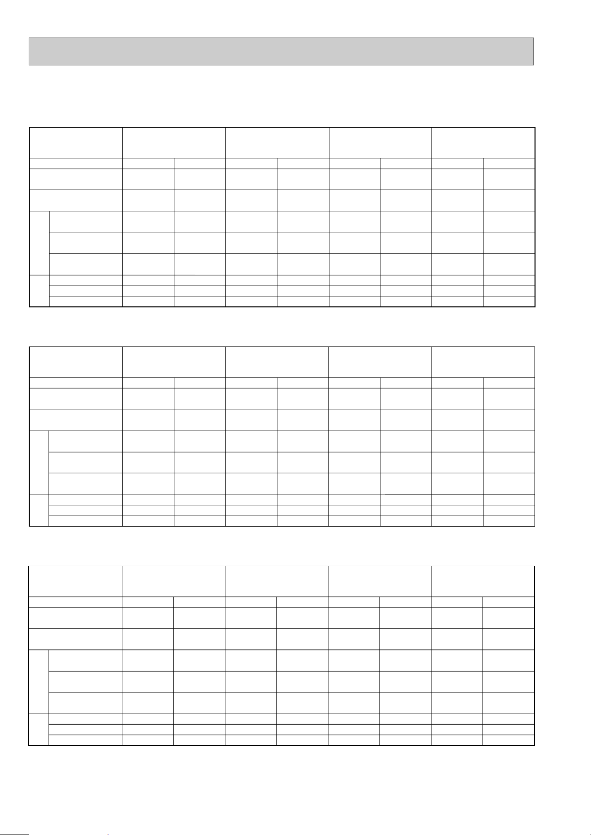
Mode
Capacity (W)
Total Input (kW)
Indoor
Outdoor
Service Ref.
Cool
7,500
3.28
0.15
0.78
1.0
3.13
14.67 / 5.23
54/34
Heat
8,200
[9,950]
3.07
[4.83]
0.15
[1.91]
0.78
[8.69]
1.0
[8.9]
2.92
13.68 / 4.88
54/34
Cool
9,500
3.41
0.24
1.25
2.0
3.35 / 3.17
16.90 / 5.29
79 / 37
Heat
10,200
[12,400]
3.40
[5.58]
0.24
[2.42]
1.25
[11.02]
2.0
[11.8]
3.35 / 3.16
16.90 / 5.28
79 / 37
Cool
12,200
4.47
0.28
1.43
2.0
4.19
7.32
60
Heat
13,600
[16,120]
4.41
[6.93]
0.28
[2.80]
1.43
[12.74]
2.0
[13.3]
4.13
7.21
60
Cool
13,800
4.96
0.32
1.64
2.0
4.64
8.10
68
Heat
15,700
[18,220]
4.88
[7.40]
0.32
[2.84]
1.64
[12.93]
2.0
[13.3]
4.56
7.96
68
PLH-3AK.UK
PLH-3AK1.UK
PLH-3AKH.UK
PLH-3AKH1.UK
PLH-4AKS.UK
PLH-4AKS1.UK
PLH-4AKHS.UK
PLH-4AKHS1.UK
PLH-5AKS.UK
PLH-5AKS1.UK
PLH-5AKHS.UK
PLH-5AKHS1.UK
PLH-6AKS.UK
PLH-6AKS1.UK
PLH-6AKHS.UK
PLH-6AKHS1.UK
3. ELECTRICAL DATA
Input (kW)
Current (A)
Starting current (A)
Input (kW)
Current (A)
Starting current (A)
Mode
Capacity (W)
Total Input (kW)
Indoor
Outdoor
Cool
7,600
3.30
0.16
0.79
1.0
3.14
14.22 / 5.21
56 / 36
Heat
8,300
[10,200]
3.09
[5.02]
0.16
[2.09]
0.79
[9.09]
1.0
[9.3]
2.93
13.27 / 4.86
56 /36
Cool
9,600
3.44
0.25
1.25
2.0
3.44 / 3.19
16.60 / 5.23
79 / 39
Heat
10,300
[12,700]
3.43
[5.82]
0.25
[2.64]
1.25
[11.49]
2.0
[12.2]
3.44 / 3.18
16.60 / 5.22
79 / 39
Cool
12,300
4.49
0.29
1.43
2.0
4.20
7.05
63
Heat
13,800
[16,560]
4.44
[7.20]
0.29
[3.05]
1.43
[13.28]
2.0
[13.9]
4.15
6.97
63
Cool
13,900
5.02
0.33
1.64
2.0
4.69
7.87
71
Heat
15,900
[18,660]
4.90
[7.66]
0.33
[3.09]
1.64
[13.46]
2.0
[13.8]
4.57
7.67
71
Service Ref.
PLH-3AK.UK
PLH-3AK1.UK
PLH-3AKH.UK
PLH-3AKH1.UK
PLH-4AKS.UK
PLH-4AKS1.UK
PLH-4AKHS.UK
PLH-4AKHS1.UK
PLH-5AKS.UK
PLH-5AKS1.UK
PLH-5AKHS.UK
PLH-5AKHS1.UK
PLH-6AKS.UK
PLH-6AKS1.UK
PLH-6AKHS.UK
PLH-6AKHS1.UK
Input (kW)
Current (A)
Starting current (A)
Input (kW)
Current (A)
Starting current (A)
Mode
Capacity (W)
Total Input (kW)
Indoor
Outdoor
Cool
7,700
3.32
0.17
0.81
1.0
3.15
13.82 / 5.16
58 / 37
Heat
8,400
[10,500]
3.11
[5.21]
0.17
[2.27]
0.81
[9.47]
1.0
[9.7]
2.94
12.89 / 4.81
58 / 37
Cool
9,700
3.46
0.26
1.25
2.0
3.52 / 3.20
16.30 / 5.24
79 / 40
Heat
10,400
[13,000]
3.45
[6.05]
0.26
[2.86]
1.25
[11.93]
2.0
[12.7]
3.52 / 3.19
16.30 / 5.22
79 / 40
Cool
12,400
4.51
0.30
1.43
2.0
4.21
6.89
65
Heat
14,000
[17,000]
4.46
[7.46]
0.30
[3.30]
1.43
[13.77]
2.0
[14.3]
4.16
6.81
65
Cool
14,000
5.07
0.34
1.64
2.0
4.73
7.74
74
Heat
16,100
[19,100]
4.92
[7.92]
0.34
[3.34]
1.64
[13.94]
2.0
[14.3]
4.58
7.50
74
Service Ref.
PLH-3AK.UK
PLH-3AK1.UK
PLH-3AKH.UK
PLH-3AKH1.UK
PLH-4AKS.UK
PLH-4AKS1.UK
PLH-4AKHS.UK
PLH-4AKHS1.UK
PLH-5AKS.UK
PLH-5AKS1.UK
PLH-5AKHS.UK
PLH-5AKHS1.UK
PLH-6AKS.UK
PLH-6AKS1.UK
PLH-6AKHS.UK
PLH-6AKHS1.UK
Indoor unit …220V 50Hz 1phase
Outdoor unit…220V 50Hz 1phase / 380V 50Hz 3phase
Indoor unit …230V 50Hz 1phase
Outdoor unit…230V 50Hz 1phase / 400V 50Hz 3phase
Indoor unit …240V 50Hz 1phase
Outdoor unit…240V 50Hz 1phase / 415V 50Hz 3phase
20
Page 21
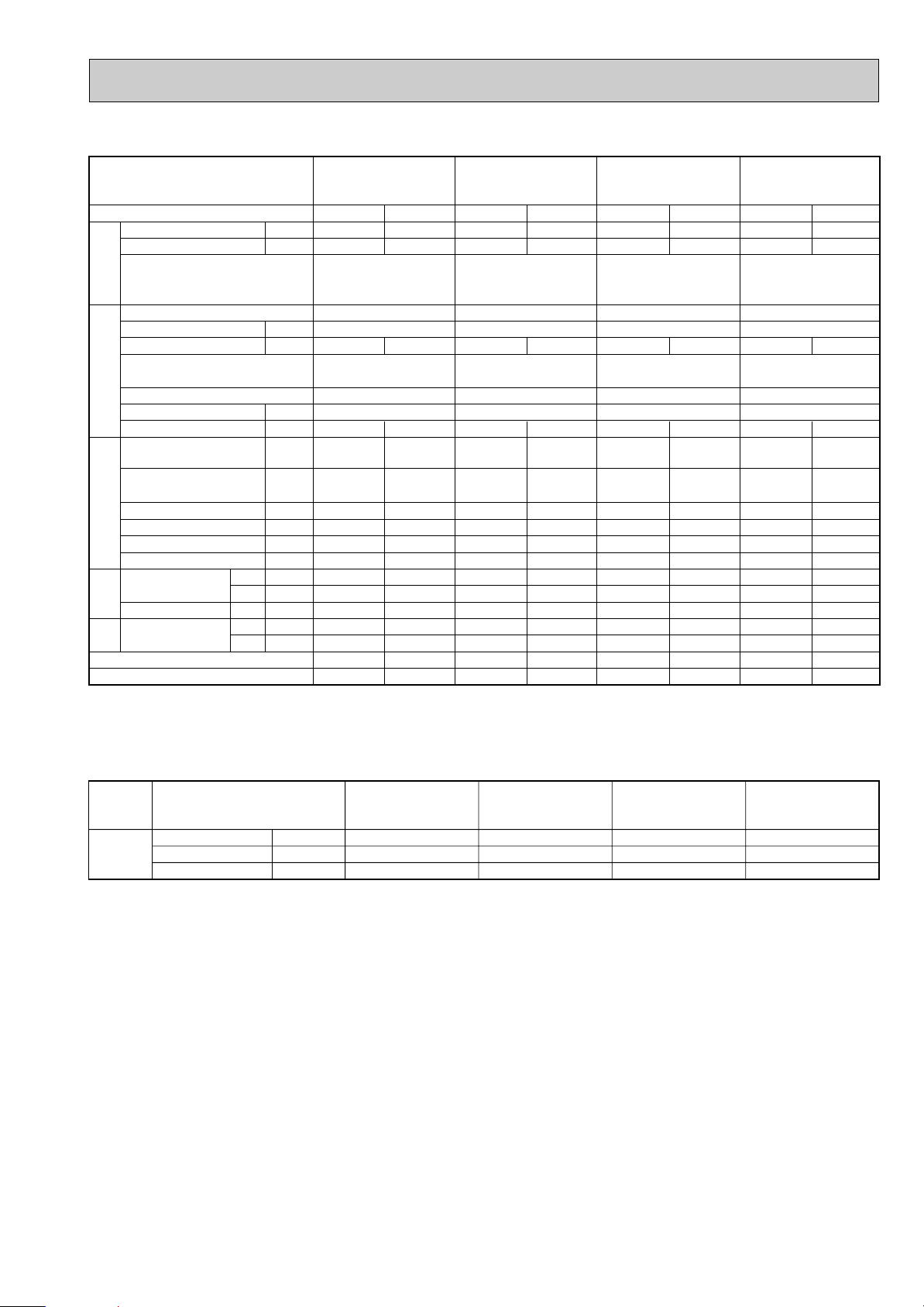
4. STANDARD OPERATION DATA
PLH-3AK.UK
Service Ref.
Mode
Capacity
Input
Total
Indoor unit Service Ref.
Phase, Hz
Volts
Amperes
Outdoor unit Service Ref.
Phase,Hz
Volts
Electrical circuitRefrigerant circuit
Amperes
Discharge pressure
Suction pressure
Discharge temperature
Condensing temperature
Suction temperature
Ref. pipe length
Intake air
temperature
side
Indoor
Discharge air temperature
Intake air
side
temperature
Outdoor
SHF
BF
D.B.
W.B.
D.B.
D.B.
W.B.
W
kW
V
A
V
A
MPa
(kgf/F)
MPa
(kgf/F)
°C
°C
°C
m
°C
°C
°C
°C
°C
PLH-3AK1.UK
PLH-3AKH.UK
PLH-3AKH1.UK
Cooling
7,700
3.32
PLH-3AK.UK
PLH-3AK
PLH-3AKH.UK
PLH-3AKH1.UK
1, 50
240
0.81 0.81
PUH-3VKA
PUH-3YKA
1/3,50
240/415
13.82/5.16
2.01
(20.5)
0.51
(5.2)
84
41
3.9
5
27
19
13.2
35
24
0.74
0.12
Heating
8,400
3.11
1.UK
2.UK
2.UK
12.89/4.81
1.89
(19.3)
0.42
(4.3)
77
—
-2.0
5
20
15
42.8
7
6
—
—
The unit of pressure has been changed to Mpa based on the international SI system.
The conversion factor is : 1(Mpa)=10.2(kgf/
FF
)
PLH-4AKS.UK
PLH-4AKS1.UK
PLH-4AKHS.UK
PLH-4AKHS1.UK
Cooling
9,700
3.46
PLH-4AKS.UK
PLH-4AKS1.UK
PLH-4AKHS.UK
PLH-4AKHS1.UK
1, 50
240
1.25 1.25
PUH-4VKSA.UK
PUH-4YKSA
3,50
415
16.30/5.24
1.81
(18.5)
0.49
(5.0)
16.30/5.22
80
41
10.5
5
27
19
13.7
35
24
0.79
0.08
Heating
10,400
3.45
2.UK
1.73
(17.6)
0.36
(3.7)
75
—
1.0
5
20
15
39.9
7
6
—
—
PLH-5AKS.UK
PLH-5AKS1.UK
PLH-5AKHS.UK
PLH-5AKHS1.UK
Cooling
12,400
4.51
PLH-5AKS.UK
PLH-5AKS1.UK
PLH-5AKHS.UK
PLH-5AKHS1.UK
1.43 1.43
PUH-5YKSA
6.89
1.85
(18.9)
0.44
(4.5)
76
46
4.0
5
27
19
12.5
35
24
0.73
0.10
1,50
240
3,50
415
Heating
14,000
4.46
2.UK
6.81
1.94
(19.8)
0.36
(3.7)
81
—
1.1
5
20
15
45.5
7
6
—
—
PLH-6AKS.UK
PLH-6AKS1.UK
PLH-6AKHS.UK
PLH-6AKHS1.UK
Cooling
14,000
Heating
16,100
5.07
PLH-6AKS.UK
PLH-6AKS1.UK
PLH-6AKHS.UK
PLH-6AKHS1.UK
1,50
240
1.64 1.64
PUH-6YKSA
3,50
415
7.74
1.90
(19.4)
0.42
(4.3)
(20.5)
74
39
4.6
5
27
19
11.2
35
24
0.71
0.06
4.92
2.UK
7.50
2.01
0.37
(3.8)
76
—
0.3
5
20
15
49.8
7
6
—
—
5. OUTLET AIR SPEED AND COVERAGE RANGE
PLH-3AK.UK
PLH-3AK1.UK
PLH-3AKH.UK
PLH-3AKH1.UK
Standard
Air flow
Air speed
Coverage range
K/min(CFM)
m/W
m
20(705)
4.0
5.7
wThe air coverage range is the value up to the position where the air speed is 0.25m/sec.
When air is blown out horizontally from the unit at the Hi notch position.
The coverage range should be used only as a general guideline since it varies according to the size of the room and the
furniture inside the room.
PLH-4AKS.UK
PLH-4AKS1.UK
PLH-4AKHS.UK
PLH-4AKHS1.UK
28(990)
4.9
7.4
PLH-5AKS.UK
PLH-5AKS1.UK
PLH-5AKHS.UK
PLH-5AKHS1.UK
30(1,060)
5.2
7.9
PLH-6AKS.UK
PLH-6AKS1.UK
PLH-6AKHS.UK
PLH-6AKHS1.UK
30(1,060)
6.6
8.9
21
Page 22
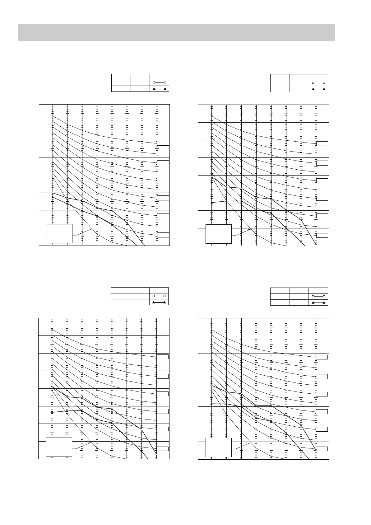
90
80
70
60
50
40
30
20
10
63 125 250 500 1000 2000 4000 8000
APPROXIMATE
THRESHOLD OF
HEARING FOR
CONTINUOUS
NOISE
NC-60
NC-50
NC-40
NC-30
NC-20
NC-70
BAND CENTER FREQUENCIES, Hz
OCTAVE BAND SOUND PRESSURE LEVEL, dB
(0 dB = 0.0002 µbar)
Hi
NOTCH
Lo
41
SPL(dB)
33
LINE
PLH-4AKS.UK
PLH-4AKS
1.UK
PLH-4AKHS.UK
PLH-4AKHS
1.UK
90
80
70
60
50
40
30
20
10
63 125 250 500 1000 2000 4000 8000
APPROXIMATE
THRESHOLD OF
HEARING FOR
CONTINUOUS
NOISE
NC-60
NC-50
NC-40
NC-30
NC-20
NC-70
OCTAVE BAND SOUND PRESSURE LEVEL, dB
(0 dB = 0.0002 µbar)
BAND CENTER FREQUENCIES, Hz
PLH-3AK.UK
PLH-3AK
1.UK
PLH-3AKH.UK
PLH-3AKH
1.UK
Hi
Lo
34
SPL(dB)28LINE
NOTCH
6. NOISE CRITERION CURVES
90
80
70
60
50
40
30
20
10
63 125 250 500 1000 2000 4000 8000
APPROXIMATE
THRESHOLD OF
HEARING FOR
CONTINUOUS
NOISE
NC-60
NC-50
NC-40
NC-30
NC-20
NC-70
BAND CENTER FREQUENCIES, Hz
OCTAVE BAND SOUND PRESSURE LEVEL, dB
(0 dB = 0.0002 µbar)
Hi
NOTCH
Lo
45
SPL(dB)
37
LINE
PLH-6AKS.UK
PLH-6AKS
1.UK
PLH-6AKHS.UK
PLH-6AKHS
1.UK
90
80
70
60
50
40
30
20
10
63 125 250 500 1000 2000 4000 8000
APPROXIMATE
THRESHOLD OF
HEARING FOR
CONTINUOUS
NOISE
NC-60
NC-50
NC-40
NC-30
NC-20
NC-70
BAND CENTER FREQUENCIES, Hz
OCTAVE BAND SOUND PRESSURE LEVEL, dB
(0 dB = 0.0002 µbar)
Hi
NOTCH
Lo
43
SPL(dB)
35
LINE
PLH-5AKS.UK
PLH-5AKS
1.UK
PLH-5AKHS.UK
PLH-5AKHS
1.UK
22
Page 23
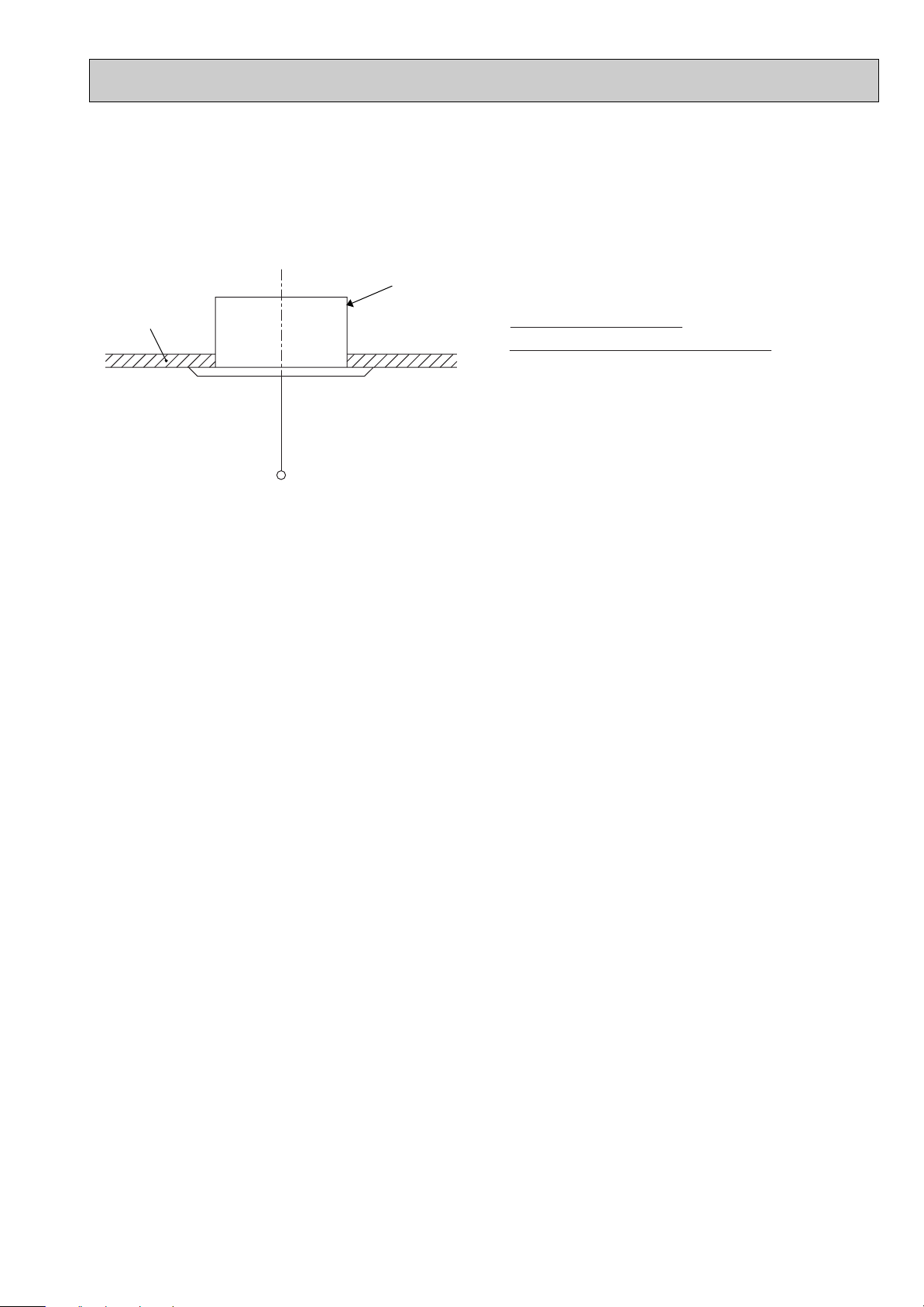
UNIT
CEILING
Ambient temperature 27:
Test conditions are based on JIS Z8731
1.5m
MICROPHONE
23
Page 24
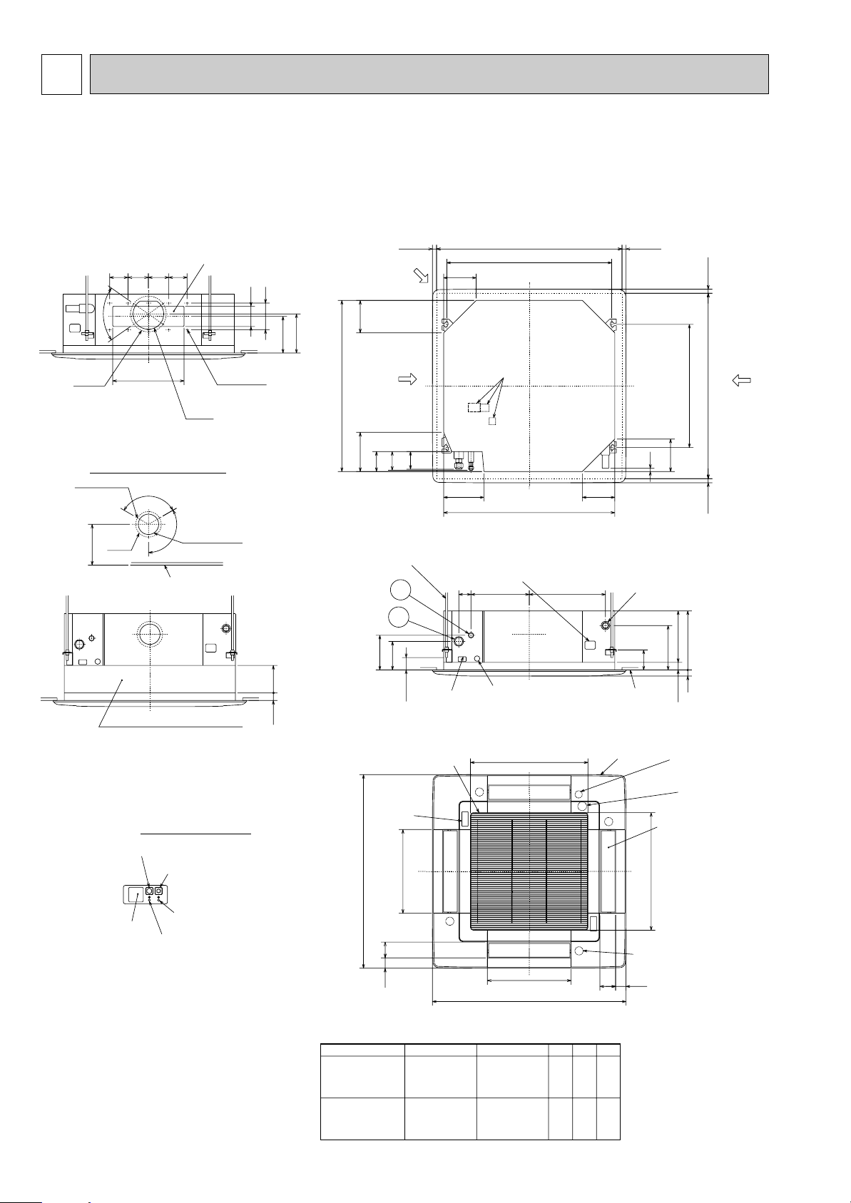
5
Air outlet hole
Vane motor
Auto vane
Emergency drain hole
(Combined with hole
fed chemicals)
Drain hole
(Combined with drain
pump cleaning hole )
Grille
Drain pipe
VP-25connection
(O.D.{32)
Branch duct hole
(Cut out hole)
Ceiling surface
Suspension bolt pitch
Ceiling hole
Branch
duct hole
Suspension bolt pitch
Ceiling hole
Air outlet hole
Air intake hole
411
Air intake hole
Air intake grille
Receiver
Operation lamp
DEFROST/STAND BY lamp
Emergency operation switch (cooling)
High efficiency filter
& Fresh air intake casement (option)
A (WIRELESS PANEL)
Emergency operation switch (heating)
Power line entry
Suspension bolt lower edge
Suspension bolt M10
or W3/8
Control wire entry
Feeding hole
(Drain pump)
577
374286
840
197 159
60
17
+5
0
17
+5
0
135
30
190
159
605
159192
170
140
50~70
98
89
C
840
860~910
20~45 20~45
20~4520~45
Fresh air intake
Branch duct hole
860~910
810
159
16
105
A
B
77 51
M
M
M
A
1
2
M
950
51 77
950
577
411
Terminal block
Deteil drawing of fresh air intake
{175
{150
14 - {2.8
Burring hole
3 - {2.8
Burring hole
{100
(Cut out hole)
{125
Ceiling surface
PLH-3AK
PLH-3AKH
Models 12
PLH-4, 5, 6AKS
PLH-4, 5, 6AKHS
Refrigerant pipe
(9.52mm dia.)
flared connection
3/8F
Refrigerant pipe
(9.52mm dia.)
flared connection
3/8F
Refrigerant pipe
(15.88mm dia.)
flared connection
5/8F
241
281
A
258
298
B
80
84
C
Refrigerant pipe
(19.05mm dia.)
flared connection
3/4F
350
120_
120_
158
90
70_
100 100 90
100
130
155
167
OUTLINES AND DIMENSIONS
1. INDOOR UNIT
PLH-3AK.UK PLH-4AKS.UK PLH-5AKS.UK PLH-6AKS.UK
PLH-3AK1.UK PLH-4AKS1.UK PLH-5AKS1.UK PLH-6AKS1.UK
PLH-3AKH.UK PLH-4AKHS.UK PLH-5AKHS.UK PLH-6AKHS.UK
PLH-3AKH1.UK PLH-4AKHS1.UK PLH-5AKHS1.UK PLH-6AKHS1.UK
Unit : mm
24
Page 25
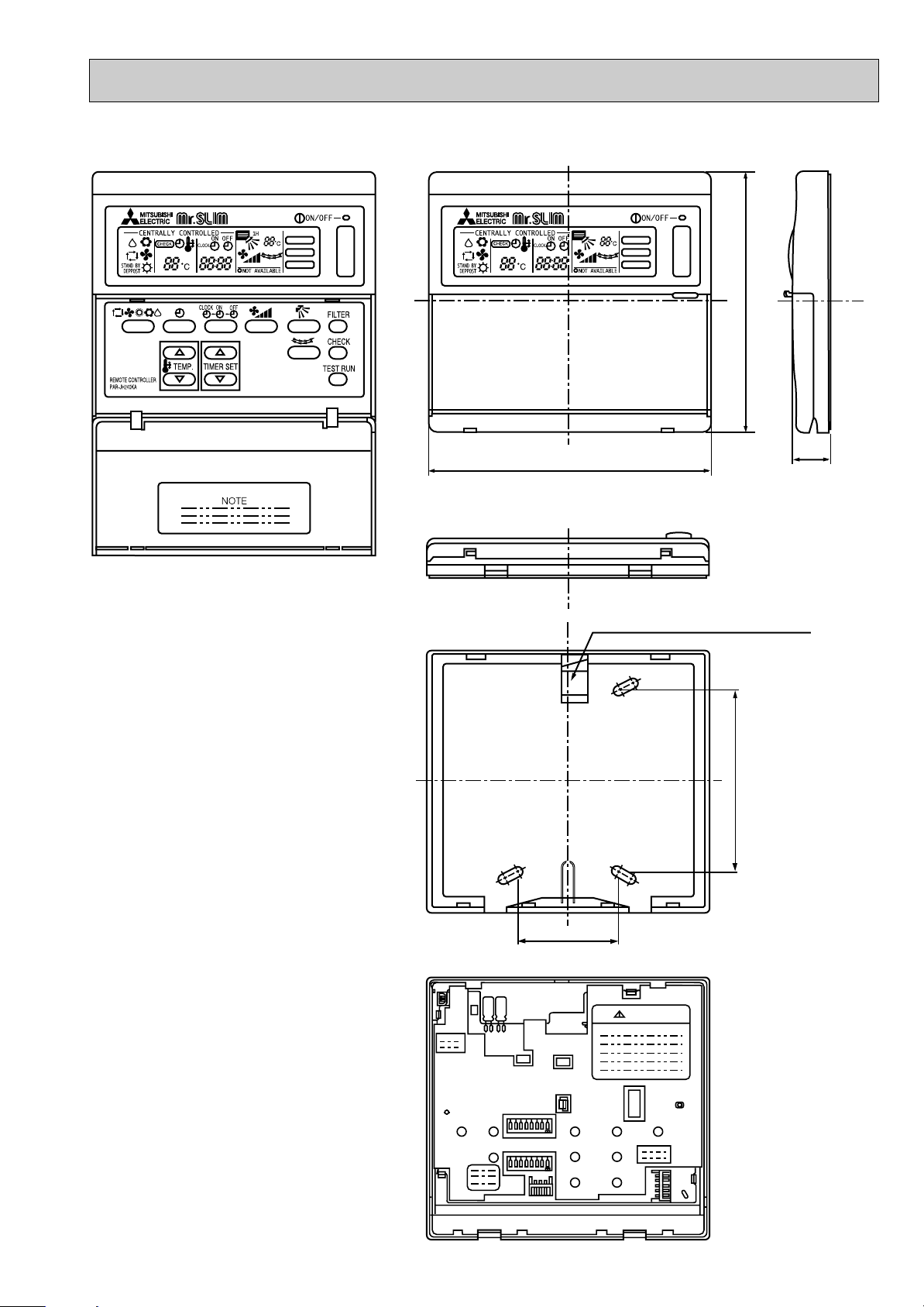
2. REMOTE CONTROLLER
18
130
Rear side wiring arrangement opening.
120
FILTER
CHECK MODE
TEST RUN
FILTER
CHECK MODE
TEST RUN
46
83.5
SW18
SW17
CAUTION
r
r
Unit : mm
25
Page 26
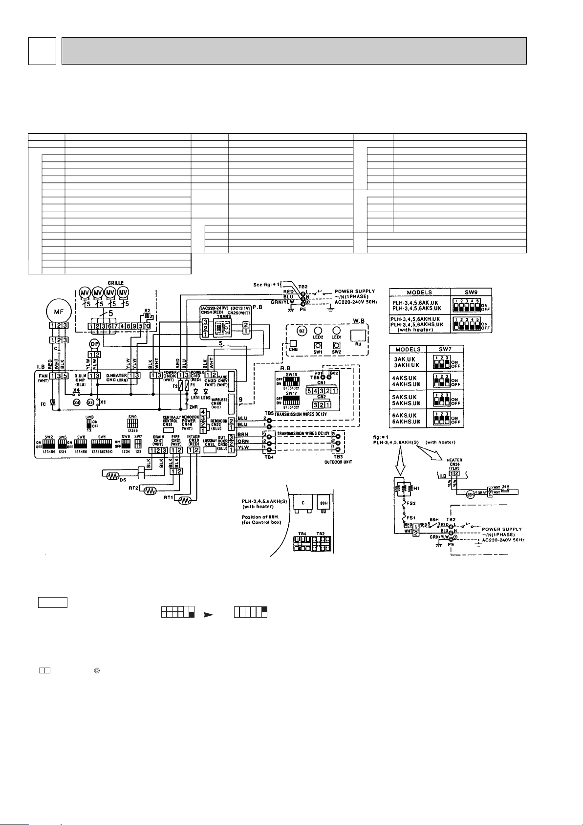
6
SYMBOL
P.B
I.B
CN1
CN2
SW17
SW18
RU
BZ
LED1
LED2
SW1
SW2
FS1
FS2
H1
26H
88H
C
MF
MV
DP
DS
H2
TB2~TB6
RT1
RT2
R.B
W.B
HEATER
CN2L
CN51
FC
SW1
SW2
SW3
SW5
SW6
SW7
SW8
SW9
X1
X4
F1, F2
ZNR
LED1
LED2
INDOOR POWER BOARD
INDOOR CONTROLLER BOARD
CONNECTOR (LOSSNAY)
CONNECTOR (CENTRALLY CONTROL)
FAN PHASE CONTROL
SWITCH (FUNCTION SELECTOR)
SWITCH (ADDRESS SELECTOR)
SWITCH (EMERGENCY OPERATION)
SWITCH (MODEL SELECTOR)
SWITCH (TWIN / TRIPLE SELECTOR)
SWITCH (MODEL SELECTOR)
SWITCH (OPTION)
SWITCH (MODEL SELECTOR)
RELAY (DRAIN PUMP)
RELAY (FAN MOTOR)
FUSE (6.3V / 250V)
VARISTOR
LED (DC 12V POWER)
LED (DC 5V POWER)
CAPACITOR (FAN MOTOR)
FAN MOTOR
VANE MOTOR
DRAIN-UP MACHINE
DRAIN SENSOR
DEW PREVENTION HEATER
TERMINAL BLOCK
ROOM TEMPERATURE THERMISTOR
(0: / 15k" , 25: / 5.4k" / DETECT)
PIPE TEMPERATURE THERMISTOR / LIQUID
(0: / 15k" , 25: / 5.4k" / DETECT)
REMOTE CONTROLLER BOARD
CONNECTOR (PROGRAM TIMER)
CONNECTOR (REMOTE SWITCH)
SWITCH (ADDRESS SELECTOR)
SWITCH (FUNCTION SELECTOR)
WIRELESS REMOTE CONTROLLER BOARD
RECEIVING UNIT
BUZZER
LED (RUN INDICATOR)
LED (HOT ADJUST)
SWITCH (HEATING ON / OFF)
SWITCH (COOLING ON / OFF)
THERMAL FUSE (72°C 16A)
THERMAL FUSE (104°C 16A)
HEATER
HEATER THERMAL SWITCH
HEATER CONTACTOR
NAME SYMBOL SYMBOLNAME NAME
WIRING DIAGRAM
PLH-3AK.UK PLH-4AKS.UK PLH-5AKS.UK PLH-6AKS.UK
PLH-3AK
1.UK PLH-4AKS1.UK PLH-5AKS1.UK PLH-6AKS1.UK
PLH-3AKH.UK PLH-4AKHS.UK PLH-5AKHS.UK PLH-6AKHS.UK
PLH-3AKH
w
1.UK PLH-4AKHS1.UK PLH-5AKHS1.UK PLH-6AKHS1.UK
w The part name of
symbol “I.B” is “SPCB”.
NOTES :
1. Since the indoor fan motor (MF) is connected with 230, 240V power. If 220V
power is used, change the dip switch (SW8) on the indoor controller board
as shown in fig : w2.
fig w2
Indoor fan motor (MF)for 220V.
ON
OFF
1
SW8
2 34
56
ON
OFF
2. Since the outdoor side electric wiring may change be sure to check the outdoor unit electric wiring for servicing.
3. Indoor and outdoor connecting wires are mode with polarities, make wiring
matching terminal numbers.
4. Symbols used in wiring diagram above are,
: Connector, : Terminal block.
5. Emergency operation
If remote controller or microcomputer fails but there is no other trouble ,
emergency operation is possible by setting dip switch (SW3<I.B>) on the
indoor controller board.
[Check items]
(1)Make sure that no other trouble exist the outdoor unit. Trouble with the out-
door unit prevents emergency operation.
(If any trouble exists the outdoor unit error code “P8”will be displayed on the
SW8
2
3 4
56
1
remote controller and the trouble position will be shown on the outdoor controller board LED. See electric wiring diagram of the outdoor unit for details.)
(2)Make sure that there is no trouble with the indoor fan.
Emergency operation will be continuous run with the power ON/OFF
(ON/OFF with the remote controller is not possible).
[Emergency operation procedure]
(1)Set the dip switch (SW3<I.B>) on the indoor controller board to
1 on and 2
off for cooling and 1 - 2 on for heating.
(2)Turn on are outdoor unit side circuit breaker, then indoor unit side circuit
breaker.
(3)During emergency operation indoor fan runs at High speed but auto-vane
does not work.
(4)Thermostat will not function. Cold air blows out for defrosting during heating
thus do not operate defrosting for a long time.
(5)Emergency cooling should be limited to 10 hours maximum.
(The indoor unit heat exchanger may freeze).
(6)After every emergency operation, set all dip switches (SW3<I.B>) to OFF.
(7)Movement of the vanes does not work in emergency operation, therefore you
have to slowly set them manually to the appropriate position.
NOTE: If the drain water lift up mechanism is identified to be defective with the
microcomputer doctor during cooling, do not use emergency operation
(it causes drain overflow)
26
Page 27
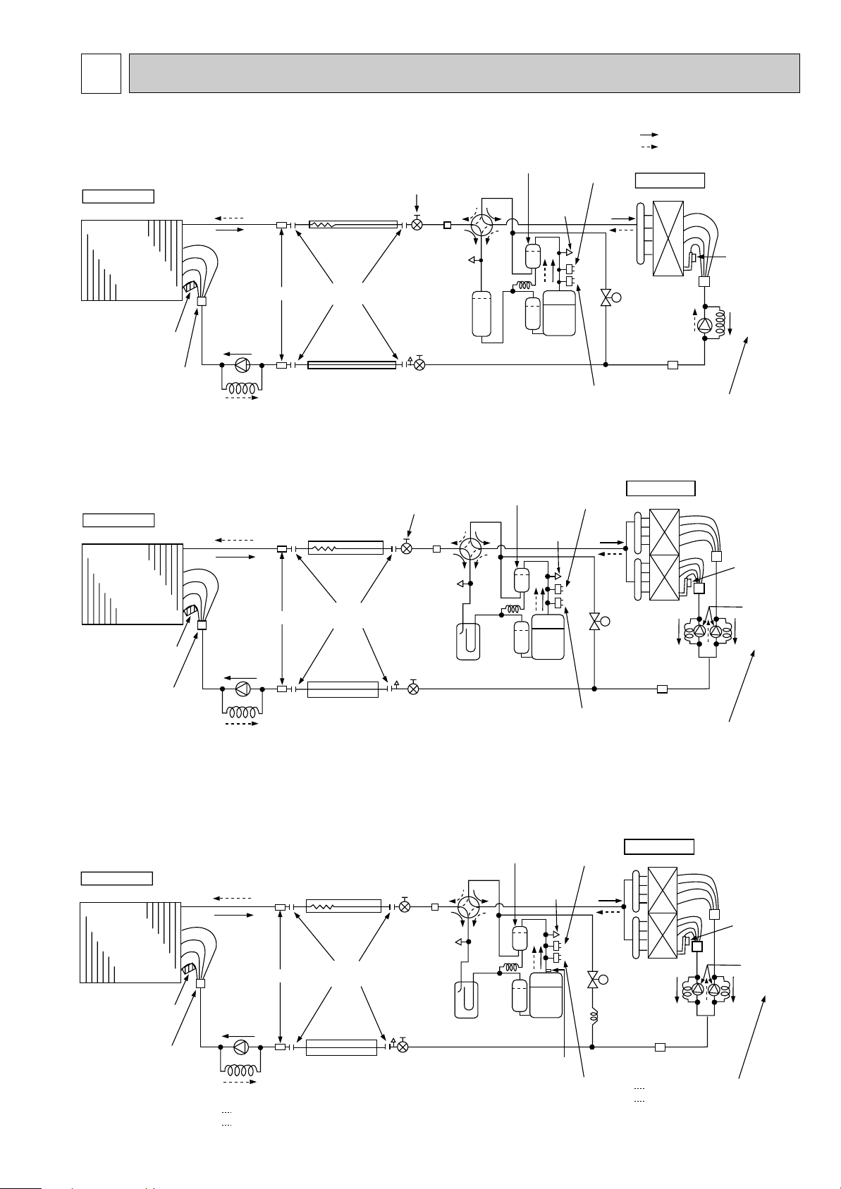
REFRIGERANT SYSTEM DIAGRAM7
Indoor unit
Indoor
heat
exchanger
Refrigerant pipe
(option)
15.88mm({5/8")
(with heat insulator)
Flexible tube
Ball valve
Strainer
4-way valve
Oil separator
Service
port
Service
port
High pressure
control switch
Protective
high pressure
switch
Outdoor unit
Outdoor heat exchanger
Thermistor
TH
Capillary
tube
Restrictor
valve
PUH-3KA --- O.D.4.0 o I.D.2.4 -L1070
Strainer
Bypass
valve
Compressor
Accumulator
Ball valve
(with service port)
Refrigerant pipe
(option)
9.52
mm({3/8")
(with heat insulator)
Capillary
tube
Restrictor
valve
Distributor
with
strainer
Thermistor
RT2
Strainer
Flared
connection
Refrigerant flow in cooling
Refrigerant flow in heating
<R.V.coil>
Heating ON
Cooling OFF
Unit : mm
O.D.4.0 o I.D.2.0 - L200
Indoor unit
Indoor
heat
exchanger
Refrigerant pipe
(option)
19.05
mm([ 3/4")
(with heat insulator)
Flexible tube
Ball valve
Strainer
4-way valve
Oil
separator
Service
port
Service
port
Outdoor unit
Outdoor heat exchanger
Thermistor
TH
Capillary
tube
Restrictor
valve
Strainer
Bypass
valve
Compressor
Accumulator
Ball valve
(with service port)
Refrigerant pipe
(option)
9.52
mm([ 3/8")
(with heat insulator)
Capillary
tube
Restrictor valve
Distributor
with
strainer
Thermistor
RT2
Strainer
Flared
connection
O.D. 4.0 o I.D. 2.0 - L 250
(O.D. 3.2 o I.D. 2.0 - L 820) o2
High pressure
switch
Protective
high pressure
switch
Indoor unit
Indoor
heat
exchanger
Refrigerant pipe
(option)
19.05
mm([3/4")
(with heat insulator)
Flexible tube
Ball valve
Strainer
4-way valve
Oil
separator
Service
port
Service
port
Outdoor unit
Outdoor heat exchanger
Thermistor
TH
Capillary tube
Restrictor
valve
Strainer
Bypass
valve
Compressor
Accumulator
Ball valve
(with service port)
Thermal Switch
Refrigerant pipe
(option)
9.52
mm([3/8")
(with heat insulator)
Capillary
tube
Restrictor valve
Distributor
with
strainer
Thermistor
RT2
Strainer
Flared
connection
PLH-5 O.D. 4.0 o I.D. 3.0 - L 550
Capillary tube
PUH-5 (O.D. 4.0 o I.D. 2.4 - L 840) o2
PUH-6 (O.D. 4.0 o I.D. 2.4 - L1200) o2
PLH-6 O.D. 4.0 o I.D. 3.0 - L 380
High pressure
control switch
Protective
high pressure
switch
PLH-3AK.UK PLH-3AK1.UK / PUH-3VKA2.UK PUH-3YKA2.UK
PLH-3AKH.UK PLH-3AKH1.UK / PUH-3VKA2.UK PUH-3YKA2.UK
PLH-4AKS.UK PLH-4AKS
PLH-4AKHS.UK PLH-4AKHS
1.UK / PUH-4VKSA.UK PUH-4YKSA2.UK
1.UK / PUH-4VKSA.UK PUH-4YKSA2.UK
PLH-5AKS.UK PLH-5AKS1.UK / PUH-5YKSA2.UK
PLH-6AKS.UK PLH-6AKS
PLH-5AKHS.UK PLH-5AKHS
PLH-6AKHS.UK PLH-6AKHS
1.UK / PUH-6YKSA2.UK
1.UK / PUH-5YKSA2.UK
1.UK / PUH-6YKSA2.UK
27
Page 28

8 OPERATION FLOW-CHART
START
Power circuit
breaker
Check SW
ON twice
Operation SW
ON
“OFF” timer
“ON” timer
STOP
Set time
complete
Set time
complete
1
NO
NO
NO
NO
NO
NO
NO
NO
NO
NO
NO
NO
YES
YES
YES
YES
YES
YES
YES
YES
YES
YES
YES
YES
w 1
w 2
w 3
w 4
w 5
w 7
w 6
PROTECTION DEVICE
SELF HOLD RELEASE
Remote controller
indicator lamp OFF
Trouble STOP
Remote controller
operation display
Operating mode
(COOL)
Operating mode
(DRY)
Operating mode
(HEAT)
Operating mode
(FAN)
Auto COOL/HEAT
operation
COOL operation
DRY operation
HEAT operation
FAN operation
Trouble
PROTECTION DEVICE
SELF HOLD
Remote controller
trouble display
Indoor side
Outdoor side
Fan STOP
Auxiliary heater OFF
Compressor OFF
Fan STOP
Four-way valve OFF
MAIN OPERATION
w1 In addition, the centralized control and remote control can be operated.
w2 The modes which indicate the sources of trouble are listed below.
● EO-Signal transmitting/receiving error
● P1-Room temperature thermistor malfunction
● P2-Pipe temperature thermistor malfunction
● P4-Drain sensor malfunction
● P5-Drain overflow
● P6-Coil frost/overheat protection
● P7-System error
● P8-Outdoor unit trouble
w3 The CHECK switch will show if an error has occurred in the past.
w4 Fan runs on low speed for 1 minute in order to remove overheat air.
w5 The 3-minute time-delay functions after compressor stops.
w6 FAN or AUTO mode is selected by the indoor dip switch setting.
w7 In FAN mode, fan speed and vane operation depend on the remote controller setting. (Compressor is OFF.)
28
Page 29

COOLING OPERATION
COOL operation
Four-way valve/OFF
NO
NO
NO
Vane setting notch
Initial
COOLING
Vane initial
setting
Vane
Fan speed
LOW
Downward
discharge
1 hour
airflow
Compressor
thermostat
ON
Allowance
cancel
NO
YES
YES
YES
YES
NO
YES
YES
NO
w 11
w 8
55 deg downward angle
70 deg downward angle
NO
Vane horizontal
w 9
YES
3-minute
time delay
6-minute
time delay
3-minute
compressor
operation
w 10
Coil frost
protection
Cooling area
NO
NO
YES
NO
YES
NO
Allowance
period
NO
6 minute
time delay
Allowance set
YES
Coil frost protection
YES
10-minute
NO
Allowance cancel
NO
temperature is
1°C or lower
Compressor ON
compressor
operation
YES
Coil frost
prevention
NO
16-minute
compressor
operation
YES
pipe
NO
1
YES
YES
Coil frost
prevention
Compressor OFF
Pipe
temperature is
10°C or higher
Defrosting protection
detection temperature
-1°C or lower
6-minute
time delay
Coil frost
prevention release
NO
YES
NO
YES
3-minute
time delay
NO
1 min continue
FAN speed
FAN speed
LOW 5 min
LOW
elapse
YES
NO
YES
Outdoor unit
trouble
w8 When operation stops or changes to cooling or dry mode, the auto vane turns to a horizontal angle. If operation changes
during auto vane SWING, the auto vane will continue to swing.
w9 When operating TEST RUN, the thermostat will be continuously ON.
w10 After 3 minute compressor operation, if the pipe temperature thermistor reads -15°C or below for 3 minutes, the compres-
sor will stop for 6 minutes.
w11 Heating area : Pipe temperature is more than 5 degrees above the room temperature.
Cooling area : Pipe temperature is more than 5 degrees below the room temperature.
FAN area : Pipe temperature is within 5 degrees either way of the room temperature.
29
Page 30

DRY OPERATION
DRY
operation
Four-way valve / OFF
Vane
setting notch
NO
YES
NO
Initial dry
operation
YES
Vane initial setting
w12
Room temperature is
18°C or lower
NO
During
compressor ON
YES
3-minute
compressor
operation
YES
Compressor &
thermostat ON
YES
w8
w9
NO
NO
YES
3-minute
time delay
NO
Compressor &
thermostat
ON
NO
YES
w9
Compressor ON
time completes
YES
10-minute compressor
OFF timer start
Compressor OFF
Fan STOP
1
w8—9 Refer to page 27.
w12 When room temperature is 18°C or below, the compressor cannot operate.
When room temperature rises over 18°C, the compressor starts after a 3-minute time delay.
w13 Compressor ON time is decided by room temperature. Refer to page 36 to 37.
w14 In dry operation, compressor ON makes the fan speed LOW. Also, when the compressor OFF and the pipe temperature
is 26°C or less, the fan stops, or when the compressor OFF and the pipe temperature is below 6°C, the fan speed
changes to LOW mode.
It is not possible to set the fan speed with the remote controller
NO
w14
10-minute
compressor
OFF
YES
Compressor ON
time set
Compressor ON
Fan speed LOW
NO
w13
w14
30
Page 31

Heat operation
initial
HEATING
Vane setting notch
Vane initial setting
defrosting
Heating area
Defrost release
Defrost
30 min. elapse
Outdoor unit trouble
Four-way valve ON
Hot adjust
in process
Compressor ON
Compressor
thermostat ON
Allowance cancel
Indoor piping
-15°C or lower
Outdoor unit
trouble
FAN SPEED
Extra low airflow
Compressor OFF
1
3 min. restart
prevention
6 min. restart
prevention
2
A
B
B
A
1
2
1
Hot adjust start
FAN SPEED very low
Compressor ON
10-minute
compressor
operation
Allowance cancel
Heating
area
FAN STOP
Fan area
20 min. elaspe
Fan area
Heating area
Outdoor unit
trouble
Fan area
Cooling area
Defrost operation
START
Four-way valve
OFF
Indoor piping
55°C or lower
Auxiliary heater
ON
Indoor piping
60°C or higher
Auxiliary heater OFF
Overheat remote
START
Indoor piping
70°C or higher
Allowance
period
Overload protect
Auxiliary heater
thermostat ON
Auxiliary heater ON
6-minute restart
prevention
Allowance set
Compressor OFF
Indoor piping
35°C or higher
HOT adjust
5 min. elapse
FAN SPEED
Low
FAN SPEED
Low 2 min.
elapse
FAN SPEED
setting notch
Hot adjust
release
PLH-AKH
Type
3-minute
Auxiliary heater
OFF
Pipe
temperature
thermistor is 60°C
or higher
FAN speed
Low notch
Airflow 10% up
FAN setting notch
Auto COOL/HEAT
operation
Initial mode
T1 ] T0
COOL mode
HEAT mode
COOL mode
T1 [ (To - 2)
After 15min.
T1 [ (To-2)
COOL operation HEAT operation
1
1
T1 ] (To + 2)
After 15min.
T1 ] (To + 2)
HEAT operation
Cool mode
set
NO
NO
NO
NO
NO
w 17
w 16
NO
NO
YES
YES
YES
YES
YES
YES
YES
NO
NO
NO
NO
NO
NO
NO
NO
NO
NO
NO
NO
NO
NO
NO
NO
NO
YES
YES
YES
NO
NO
NO
NO
NO
NO
NO
NO
NO
NO
NO
NO
w 11
w 11
w 11
w 9
w 15
w 11
w 10
YES
YES
YES
YES
YES
YES
YES
YES
YES
YES
YES
YES
YES
YES
YES
YES
YES
YES
YES
YES
YES
YES
YES
YES
YES
HEATING OPERATION
AUTOMATIC COOLING/HEATING OPERATION
w15 ( i )Until Low airflow is set while in hot adjustment
w16 When AUTO operation is started, COOLor HEAT mode is selected automatically.
w17 T1 : Room temperature.
(ii )While defrosting (FAN STOP)
(iii)When thermostat is OFF
In the case of( i ), (ii) and (iii) above, airflow is horizontal regardless the VANE setting.
To : Set temperature
31
Page 32

9
FILTER
CHECK MODE
TEST RUN
ON/OFF
CHECK
ADDRESS
UNIT No.
FUNCTION No.
SELECTION No.
AM
PM
AM
PM
TEST RUN
FUNCTION
˚C
TEMP.
MICROPROCESSOR CONTROL
1. OUTLINE OF MICROPROCESSOR CONTROL
INPUT to remote controller
● OFF-ON switching.
● COOL/DRY-AUTO-HEAT selector switching.
● Thermostat setting.
● TIMER mode selector-switching and Timer
setting.
● HIGH-LOW fan speed switching.
● AUTO Vane selector (AIR DISCHARGE)
switching.
● TEST RUN switching.
● CHECK mode switching.
(Self diagnostic trouble shooting)
Indoor
unit
Remote controller board
● Processes and transmits
orders.
Non-polar, two-wire
cable maximum
length 500 meters
(WIRED only)
Signal
12VDC
OUTPUT to remote controller
Remote controller
● LCD indicator
WIRED REMOTE
CONTROLLER
INPUT from indoor unit
● Room temperature thermistor (RT1)
● Pipe temperature thermistor (RT2)
● Drain sensor
OUTPUT to indoor unit
● Auto vane’s angle setting.
● Booster heater ON-OFF Control.
● Drain pump : ON-OFF.
● Emergency stop.
Independent Control of
Outdoor Unit
● Compressor protection
device working
● Defrosting
START-STOP
● Fan speed control.
● Crankcase heater control
ON-OFF.
● Self diagnostic function
Indoor controller board
● Receives orders from remote controller and
temperature data from indoor unit.
● Processes orders and data.
● Controls indoor and outdoor operation.
● Self diagnostic function.
w System control operation.
w Emergency operation.
w Set by dip switch on indoor controller board.
● Transmits the power to remote controller.
123
Polar three-wire cable
Outdoor unit
12VDC
1
2
3
WIRELESS
REMOTE
CONTROLLER
● Compressor and
outdoor fan : ONOFF.
● Operation mode
OUTPUT to outdoor unit
change :COOLHEAT.
32
Page 33

2. INDOOR UNIT CONTROL
Minimum 3 minutes w1
ON
Thermostat
Indoor fan
Auto vane
Drain pump
Booster heater
Compressor
ON
ON
LOW or HIGH LOW or HIGH
ON
ON
OFF
OFF
ON
OFF
3 minutes
OFF
OFF
OFF
OFF
Operation starts by
POWER button
ON.
Operation stops by
POWER button
OFF.
Room temperature
becomes equal to
set temperature.
Room temperature
rises above set
temperature.
FILTER
CHECK MODE
TEST RUN
ON/OFF
CHECK
ADDRESS
UNIT No.
FUNCTION No.
SELECTION No.
AM
PM
AM
PM
TEST RUN
FUNCTION
˚C
TEMP.
2-1 COOL operation
<How to operate>
1 Press POWER ON/OFF button.
2 Press the button to display
3 Press the TEMP. button to set the desired temperature.
NOTE: Set temperature changes 1°C when the or
button is pressed one time.
Cooling 19 to 30°C
WIRED REMOTE
CONTROLLER
PLH-3AK.UK
PLH-3AKH.UK
PLH-4, 5, 6AKS.UK
PLH-4, 5, 6AKHS.UK
WIRELESS REMOTE
<COOL operation time chart>
PLH-3AK1.UK
PLH-3AKH1.UK
PLH-4, 5, 6AKS1.UK
PLH-4, 5, 6AKHS1.UK
CONTROLLER
w1 Even if the room temperature rise above the set temperature during this period, the compressor will not start
until this period has ended.
(1) Compressor control
1 3-minute time delay
To prevent overload, the compressor will not start within 3 minutes after stop.
2 The compressor runs when room temperature is higher than set temperature.
The compressor stops when room temperature is equal to or lower than the set temperature.
The compressor maintains the previous state when the discharge temperature minus the set temperature is 0°C or more, or
lower than 1°C.
3 The compressor stops in check mode or during protective functions.
4 Coil frost prevention
To prevent indoor coil frost, the compressor will stop when the pipe thermistor (RT2) reads 1°C or below after the compressor has been continuously operated for at least 16 minutes or more. When the pipe temperature rises to 10°C or above, the
compressor will start in a 3-minute(w2) time delay.
w2 When the pipe temperature is -1°C or less, the compressor starts in 6 minutes.
NOTE : By turning OFF the dip switch SW1-3 on indoor controller board, the start temperature of coil frost prevention changes
from 1°C to -3°C.
33
Page 34

5 Coil frost protection
30 55 70
30
45
55
70
AUTO RETURN
When the pipe temperature becomes -15°C or below,coil frost protection will proceed as follows.
<Start condition>
After the compressor has been continuously operated for 3 minutes or more,and the pipe temperature has been -15°C
or below for 3 minutes,the coil frost protection will start.
<Coil frost protection>
Compressor stops for 6 minutes, and then restarts.
lf the start condition is satisfied again during the first 10 minutes of compressor operation, both the indoor and outdoor
units stop, displaying a check code of “P6” on the remote controller.
<Termination conditions>
Coil frost protection is released when the start condition is not satisfied again during the allowance, or when the COOL
mode stops or changes to another mode.
(2) Indoor fan control
Indoor fan speed LOW/HIGH depends on the remote controller setting.
However, if an outdoor unit abnormality is detected, the indoor fan speed will be LOW, regardless of the remote controller
setting.
(i ) Fan speed LOW/HIGH depends on the remote controller setting regardless of the thermostat ON/OFF.
(ii) Fan speed will remain on LOW if an abnormality in outdoor unit is detected. (5 minutes)
NOTE : Fan stops immediately if the unit stops or the check mode is started.
(3) Auto vane control
Auto vane position is set to 30 degrees airflow at the start-up of COOL operation.
(a) Vane position set mode & swing mode.
( i ) Every time button is pressed, setting will be changed .
(ii) Airflow direction can be changed with button.
1 Fan speed : LOW
30°
55°
70°
SWING
2 Fan speed : HIGH
30°
45°
55°
70°
SWING
<VANE POSITION>
1 Fan speed : LOW
2 Fan speed : HIGH
When 55 degrees or 70 degrees airflow is selected with the LOW fan speed in COOL operation, “1Hr” will appear right side
of the air direction display. One hour later, the airflow direction returns to 30 degrees automatically and “1Hr” will disappear. If the airflow direction is set to 30 degrees during “1Hr” indication, the time counting for AUTO RETURN is cancelled.
34
Page 35

(4) Detecting abnormalities in the outdoor unit
After the compressor has been continuously operated for 3 minutes, if the difference between the pipe temperature and
room temperature is out of RANGE C for 1 minute, the indoor fan speed will turn to LOW. Five minutes later, if the difference is still out of RANGE C,the outdoor unit is functioning abnormally. Thus, the compressor stops and check code “P8”
appears on remote controller.
RANGE A: Pipe temperature is more than 5 degrees above the room temperature.
RANGE B : Pipe temperature is within 5 degrees either way of the room temperature.
RANGE C : Pipe temperature is more than 5 degrees below the room temperature.
Pipe temperature
minus room temperature
(degree)
+5
0
-5
(5) Drain pump control
The drain pump works in COOL or DRY operation. When operation stops or changes to HEAT mode, the drain pump continues to operate for 3 more minutes. The drain pump does not work in check mode.
<Drain sensor>
When both the drain pump and unit are operating, the drain sensor detects the temperature. This temperature tells
whether the drain water level is above or under the drain sensor. If the drain water level rises above the drain sensor due
to a drain pump malfunction, the unit will stop operating in order to prevent drain from overflowing. The check code “P5” on
the remote controller will display this occurrence.
(6) Dew prevention heater
To prevent dew from accumulating on the grille, the dew prevention heater is continuously ON during COOL operation.
It is independent of the thermostat ON/OFF.
RANGE A
RANGE B
RANGE C
35
Page 36

Minimum 3 minutes w1
ON
Thermostat
Indoor fan
Auto vane
Drain pump
Booster heater
Compressor
ON
ON
DRY MODE
DRY MODE
ON
ON
OFF
OFF
ON
OFF
3 minutes
OFF
OFF
OFF
OFF
Operation starts by
POWER button
ON.
Operation stops by
POWER button
OFF.
Room temperature
becomes equal to
set temperature.
Room temperature
rises above set
temperature.
2-2 DRY operation
FILTER
CHECK MODE
TEST RUN
ON/OFF
CHECK
ADDRESS
UNIT No.
FUNCTION No.
SELECTION No.
AM
PM
AM
PM
TEST RUN
FUNCTION
˚C
TEMP.
<How to operate>
1 Press POWER ON/OFF button.
2 Press the button to display “ ”
3 Press the TEMP. button to set the desired temperature.
NOTE: The set temperature changes 1°C when the or
button is pressed one time.
Dry 19 to 30°C
WIRED REMOTE
CONTROLLER
<DRY operation time chart>
PLH-3AK.UK
PLH-3AKH.UK
PLH-4, 5, 6AKS.UK
PLH-4, 5, 6AKHS.UK
PLH-3AK1.UK
PLH-3AKH1.UK
PLH-4, 5, 6AKS1.UK
PLH-4, 5, 6AKHS1.UK
WIRELESS REMOTE
CONTROLLER
w1 Even if the room temperature rises above the set temperature during this period, the compressor will not start until
this period has ended.
(1) Compressor control
13-minute time delay
To prevent overload, the compressor will not start within 3 minutes after stop.
2The compressor stops in check mode or during protective functions.
36
Page 37

3The compressor will not start when the room temperature is below 18°C.
Compressor OFF
6°C or more
Below 6°C
STOP
Pipe temp. Fan
LOW
All LOW
Compressor ON
The compressor starts intermittent operation when the power is turned ON with room temperature above 18°C. The compressor ON/OFF time depends on the thermostat ON/OFF and the following room temperatures.After 3-minute compressor operation,
● If the room temperature thermistor reads above 28°C with thermostat ON, the compressor will operate for 6 more minutes and then stop for 3 minutes.
● If the room temperature thermistor reads 26°C~28°C with thermostat ON, the compressor will operate for 4 more minutes and then stop for 3 minutes.
● If the room temperature thermistor reads 24°C~26°C with thermostat ON, the compressor will operate for 2 more minutes and then stop for 3 minutes.
● If the room temperature thermistor reads below 24°C with thermostat ON, the compressor will stop for 3 minutes.
● If the thermostat is OFF regardless of room temperature, the compressor will stop for 10 minutes.
4Coil frost protection
Coil frost protection in DRY operation is the same as in COOL operation.
5Coil frost prevention
Coil frost prevention does not operate in DRY operation.
(2) Indoor fan control
The indoor fan runs on LOW speed during compressor operation. The fan speed cannot be changed with the remote controller. Also, the fan runs on LOW speed when the pipe temperature is 6°C or more, or the compressor is OFF and the pipe
temperature is below 6°C.
(a)During compressor OFF
● When the pipe temperature is 6°C or above, the indoor fan will stop.
● When the pipe temperature is below 6°C, the indoor fan will run on LOW speed.
(b)During compressor ON
● The indoor fan runs on LOW speed.
<Dry mode>
The fan notch is controlled by the pipe temperature every 30 seconds.
Fan control in DRY operation.
(3) Auto vane & drain pump controls
Same as in COOL operation
(4) Detecting abnormalities in the outdoor unit
An abnormality in the outdoor unit can not be detected in DRY operation.
37
Page 38

2-3 HEAT operation
Minimum 3 minutes w2
ON
Thermostat
Indoor fan
Auto vane
Drain pump
Booster heater
Compressor
Power ON lamp
STAND BY lamp
ON
ON
LOW or HIGHLOW or HIGH
ON
ON
OFF
OFF
OFF
OFF
Horizontal Horizontal
OFF
OFF
ON
OFF
ON
OFF
ON
OFF
Extra LOW
w
1Extra LOW 1
Hot adjustment
From POWER ON until
warm begins to blow
Hot adjustment
Depends on remote
controller setting
Depends on remote
controller setting
w
1 Changeable by indoor
dipswitch SW1-5
and SW1-6 .
OFF during thermostat OFF
hot adjustment
defrosting
LOW
Operation starts by
POWER button
ON.
Operation stops by
POWER button
OFF.
Room temperature
becomes equal to
set temperature.
Room temperature
falls below set temperature.
FILTER
CHECK MODE
TEST RUN
ON/OFF
CHECK
ADDRESS
UNIT No.
FUNCTION No.
SELECTION No.
AM
PM
AM
PM
TEST RUN
FUNCTION
˚C
TEMP.
WIRED REMOTE
CONTROLLER
<HEAT operation time chart>
PLH-3AK.UK
PLH-3AKH.UK
PLH-4, 5, 6AKS.UK
PLH-4, 5, 6AKHS.UK
PLH-3AK1.UK
PLH-3AKH1.UK
PLH-4, 5, 6AKS1.UK
PLH-4, 5, 6AKHS1.UK
WIRELESS REMOTE
CONTROLLER
<How to operate>
1 Press POWER ON/OFF button.
2 Press the button to display “ ”
3 Press the TEMP. button to set the desired temperature.
NOTE: The set temperature changes 1°C when the or
button is pressed one time.
Heating 17 to 28°C
<Display in HEAT operation>
[DEFROST]
The [DEFROST] symbol is only displayed during the defrost operation.
[STANDBY]
The [STANDBY] symbol is only displayed from the time the heating
operation starts until the heated air begins to blow.
w2 Even if the room temperature falls below the set temperature during this period, the compressor will not start until this period
has ended.
38
Page 39

(1) Compressor control
13-minute time delay
To prevent overload, the compressor will not start within 3 minutes after stop.
2The compressor runs when the room temperature is lower than the set temperature.
The compressor stops when the room temperature is equal to or higher than the set temperature.
3The compressor stops in check mode or during protective functions.
4Overheat protection
<Start condition>
When the pipe temperature thermistor reads 70°C or above, the overheat protection will start.
<Overheat protection>
The compressor stops for 6 minutes, and then restarts.
If the start condition is satisfied again within 10 minutes of compressor operation, both the indoor and outdoor units stop,
displaying a check code of “P6” on the remote controller.
<Termination conditions>
Overheat protection is terminated when the start condition is not satisfied again during the allowance (10-minute compressor operation), when operation mode changes to other mode, or when thermostat turns OFF.
(2) Indoor fan control
(a) Normal control
( i )The indoor fan runs on EXTRA-LOW speed during the thermostat OFF.
EXTRA-LOW speed can be changed to LOW or HIGH speed by setting the dip switch SW1-5 and SW1-6.
If the pipe temperature becomes more than 5 degrees below the room temperature during the thermostat OFF, the
indoor fan will stop. After, when the pipe temperature becomes within 5 degrees of room temperature, the indoor fan
will run on EXTRA-LOW speed.
(ii)Hot adjustment
Hot adjustment is a warm-up for HEAT operation
<Start conditions>
The hot adjustment works under any of the following conditions.
● HEAT operation starts.
● Defrosting ends.
● Thermostat turns ON.
[Hot adjustment]
Initially, the indoor fan runs on EXTRA-LOW speed. When 5 minutes have passed or the pipe temperature exceeds
35°C, the fan speed changes to LOW. 2 minutes later, the hot adjustment ends. Then, the fan speed depends on
the remote controller setting.
(iii)The indoor fan stops when the pipe temperature is within 5 degrees either way of room temperature.
(iv)To eliminate the remaining heat, the indoor fan runs for the first 1 minute after the booster heater is turned OFF.
(3) Auto vane control
Auto vane position is set to 70 degrees airflow at the start-up of HEAT operation.
(a) Vane position set mode & swing mode.
( i ) Every time button is pressed, setting will be changed .
(ii) Airflow direction can be changed with button.
30°
NOTE : In the following cases, the discharge direction is 30° regardless of the remote controller setting.
1 During the hot adjustment with fan speed at EXTRA-LOW
2 During defrosting with indoor fan OFF
3 During thermostat OFF
(4) Booster heater control (PLH-3AKH.UK, PLH-4AKHS.UK, PLH-5AKHS.UK, PLH-6AKHS.UK)
When the room temperature is 3 degrees below the set temperature, the booster heater will turn ON.
When the room temperature is equal to the set temperature, booster heater will turn OFF.
During the hot adjustment, the booster heater will not work.
<Overheat prevention>
When the pipe temperature thermistor rises to 60°C or above, the booster heater cannot work.
When the pipe temperature thermistor falls to 55°C or below, the booster heater can work.
45° 55°
70° SWING
39
Page 40

(5) Detecting abnormalities in the outdoor unit
When the outdoor unit is determined to be abnormal by the following causes, the compressor will stop and the check code
“ P8 ” will appear on the remote controller display.
( i ) During compressor ON while hot adjustment is set.
1 If the difference between the pipe temperature and room temperature is in the RANGE B, the indoor fan will stop.
2 Within 20 minutes after entering RANGE B (except for the first 10 seconds),
a) If the temperature difference enters RANGE A, the hot adjustment starts,
b) If the temperature difference is still in RANGE B, the outdoor unit is deemed abnormal.
c) If the temperature difference enters RANGE C, defrosting starts.
3 Within 20 minutes after entering RANGE C, if the temperature difference does not return to RANGE B, the outdoor
unit is deemed abnormal.
4 If the temperature difference returns to RANGE B, the next 20 minutes is an allowance period. If the difference enter
RANGE Aduring the allowance, defrosting ends and the hot adjustment starts. If the difference does not enter
RANGE Aduring the allowance, the outdoor unit is deemed abnormal.
( ii ) During compressor ON in defrosting
After 30 minutes of defrosting in hot adjustment, if the temperature difference is still in RANGE C, the outdoor unit is
determined to be abnormal.
When RANGE B does not change to RANGE Aafter 20 minutes have passed since RANGE C had outdoor unit is
determined to be abnormal.
( iii ) During compressor OFF
Not detecting abnormalities.
(6) Pipe temperature abnormality detection
An abnormality can be detected during compressor ON, except for the following.
●For the first 30 minutes after the temperature difference between the pipe temperature and room temperature enters the
RANGE C.
●When the temperature difference enters the RANGE C until it moves to the RANGE B.
w1
(7) Defrosting operation
After the outdoor unit starts the defrosting operation, when the temperature difference between the pipe temperature and
room temperature gets out of RANGE Aand into RANGE B, the indoor unit starts the defrosting mode. After the outdoor
unit stops the defrosting operation, when the temperature difference returns to the RANGE A, the indoor unit stops the
defrosting mode. While the indoor unit is in the defrosting mode, the indoor fan and the booster heater stop.
w1 RANGE A: Pipe temperature is more than 5 degrees above the room temperature.
RANGE B : Pipe temperature is within 5 degrees either way of the room temperature.
RANGE C : Pipe temperature is more than 5 degrees below the room temperature
Pipe temperature
minus room temperature
(degree)
+5
0
-5
RANGE A
RANGE B
RANGE C
40
Page 41

2-4 AUTO operation (Automatic COOL/HEAT change over operation)
Mode change (HEAT COOL)
When room temperature becomes2degrees above the set temperature,the operation mode can not be changed
for 15 minutes.
(degree)
To+2
To:Set temperature (19 28 )
To+1
To
To- 1
To- 2
Compressor
Start
HEAT mode HEAT mode
Mode change
15 minutes
15 minutes
Minimum 3 minutes
COOL mode
(COOL HEAT)
ON
OFF
-9 0 1020304046
-8.5
Cooling range
(Outside air temperature)
Heating range
-5
FILTER
CHECK MODE
TEST RUN
ON/OFF
CHECK
ADDRESS
UNIT No.
FUNCTION No.
SELECTION No.
AM
PM
AM
PM
TEST RUN
FUNCTION
˚C
TEMP.
<How to operate>
1 Press POWER ON/OFF button.
2 Press the button to display “ ”
3 Press the TEMP. button to set the desired temperature.
NOTE: The set temperature changes 1°C when the or
Automatic 19 to 28°C
●“AUTOMATIC” works to change by itself the operation
mode either to cooling or heating according to the room
WIRED REMOTE
CONTROLLER
PLH-3AK.UK
PLH-3AKH.UK
PLH-4, 5, 6AKS.UK
PLH-4, 5, 6AKHS.UK
1.UK
PLH-3AK
PLH-3AKH1.UK
PLH-4, 5, 6AKS1.UK
PLH-4, 5, 6AKHS1.UK
temperature.
WIRELESS REMOTE
CONTROLLER
(1) Initial mode
1 When AUTO operation starts after unit OFF.
● If the room temperature is higher than the set temperature, operation starts in COOL mode.
● If the room temperature is equal to or lower than the set temperature, operation starts HEAT mode.
2 When AUTO operation starts after COOL or HEAT operation, the previous mode continues.
(2 ) Mode change
1 HEAT mode changes to COOL mode when 15 minutes have passed since the room temperature became 2 degrees
above the set temperature.
2 COOL mode changes to HEAT mode when 15 minutes have passed since the room temperature became 2 degrees
below the set temperature.
button is pressed one time.
(3) Temperature range
AUTO operation is available under the outside air temperatures as follows.
41
Page 42

30°
1
45° downward
2
55° downward
3
70° downward
4
swing
5
2-5 Auto vane control
FILTER
CHECK MODE
TEST RUN
ON/OFF
CHECK
ADDRESS
UNIT No.
FUNCTION No.
SELECTION No.
AM
PM
AM
PM
TEST RUN
FUNCTION
˚C
TEMP.
<How to operate>
To change the air flow direction, press button.
WIRED REMOTE
CONTROLLER
PLH-3AK.UK
PLH-3AKH.UK
PLH-4, 5, 6AKS.UK
PLH-4, 5, 6AKHS.UK
PLH-3AK1.UK
PLH-3AKH1.UK
PLH-4, 5, 6AKS1.UK
PLH-4, 5, 6AKHS1.UK
WIRELESS REMOTE
CONTROLLER
1
30°
2
45°
3
55°
4
70°
Available in COOL operation with fan speed on HIGH or
in HEAT operation.
Unavailable in DRY operation.
If fan speed changes from HIGH to LOW during 45°
downward airflow in COOL mode, the direction automatically changes to 30°.
Changes by press-
ing the button.
(1) COOL/DRY operation
At the start-up of COOL or DRY operation, the airflow direction in automatically set to 30°. After, it can be changed to
another direction with button on the remote controller.
<Auto return>
When 55° or 70° airflow is set with fan speed in LOW, “1Hr” appears right side of the air direction. One hour later the
direction changes to 30 degrees, automatically and “1Hr” disappears.
(2) HEAT operation
At the start-up of HEAT operation, airflow direction depends on the setting of the last operation.
After, it can be changed to another direction with button. The airflow direction shifts to 30° regardless of the remote
controller settings under any of the following conditions.
● Thermostat OFF
● Defrosting
● Indoor fan speed EXTRA-LOW in hot adjustment
42
Page 43

TIMER SET
TIMER SET
2-6 TIMER operation
OFF
ON/OFF
CHECK
ADDRESS
UNIT No.
FUNCTION No.
SELECTION No.
AM
PM
RESET
AM
PM
TEST RUN
FUNCTION
˚C
MODE FAN
VANE
TEMP.
START
STOP
HR.
MIN.
ON/OFF TEMP
FAN
VANE
TEST RUN
AUTO STOP
AUTO START
h
min
LOUVER
MODE
CHECK
RESETSET CLOCK
MODEL SELECT
NOT AVAILABLE
CHECK
TEST RUN
˚C
AMPM
AMPM
h
min
AUTO STOP
AUTO START
(1) WIRED REMOTE CONTROLLER
FILTER
CHECK MODE
TEST RUN
<Timer setting example>
This setting will stop the air conditioner in 8 hours.
With the lapse of time, time display changes in 1 hour units, showing remaining time.
(2) WIRELESS REMOTE CONTROLLER
PLH-3AK.UK PLH-4, 5, 6AKS.UK
PLH-3AKH.UK PLH-4, 5, 6AKHS.UK
B
A
1
24
<Timer function>
AUTO STOP ·········The air conditioner stops after the set time lapses.
AUTO START ········The air conditioner starts after the set time lapses.
AUTO OFF ············Timer is not active.
<How to operate>
1. Press “ ” ON/OFF button.
2. Press “ ” button to select AUTO STOP or AUTO START.
3. Press “ ” button to set desired time.
Time setting is in 1 hour units for up to 24 hours.
Each time “ ” button is pressed, set time increases by 1 hour.
When “ ” button is pressed and held, the set time increases
by 1 hour every 0.5 seconds.
4. To cancel the timer operation, press “ ” ON/OFF button.
<How to operate>
1 Press the ON/OFF button to turn it ON.
2 Press the STOP or START button (TIMER SET).
·Time can be set while the following symbol is displayed.
OFF timer : A “ ” , B “ ” is displayed.
ON timer : A “ ” , B “ ” is displayed.
3 Use the HR. and MIN. buttons to set the desired time.
4 Cancelling the timer.
To cancel the OFF timer, press the STOP button.
To cancel the ON timer, press the START button.
▼
▼
PLH-3AK
1.UK PLH-4, 5, 6AKS1.UK
PLH-3AKH1.UK PLH-4, 5, 6AKHS1.UK
1
3
·It is possible to combine both OFF and ON timers.
·Pressing the “ ” ON/OFF button of the remote controller during
timer mode to stop the unit will cancel the timers.
<How to operate>
1 Push POWER ON/OFF button.
2 Check if or not the current time is correct.
3 Push the or button and select the desired
time.
4 Set the timer time using and buttons.
3
4
43
Page 44

ON/OFF
CHECK
ADDRESS
UNIT No.
FUNCTION No.
SELECTION No.
AM
PM
RESET
AM
PM
TEST RUN
FUNCTION
˚C
MODE FAN
VANE
TEMP.
START
STOP
HR.
MIN.
2-7 Test run
(1) WIRED REMOTE CONTROLLER
<Before test run>
● After installing, wiring, and piping the indoor and outdoor units, check for refrigerant leakage, looseness in power supply or
control wiring, and mistaken polarity.
● Use a 500-volt megohmmeter to check the resistance between the power supply terminal block and ground to make sure
that it is at least 1.0MΩ.
Attention:
Do not use the air conditioner if resistance is less than 1.0MΩ.
Remote controller
TEST RUN button
TEST RUN
Indoor coil temperature code
TEST RUN
Display
Display
Turn on main switch.12 hours before proceeding to step 2 to allow
1
for crankcase heater operation.
Push the TEST RUN button twice and indication of TEST RUN will
2
be shown on the liquid crystal display.
Press the button to display , COOL/DRY(or HEAT)to
confirm that cool (or warm) air is blown out.
3
(At heating operation, there may be a short delay before warm air
begins to blow out.)
Push button LOW/HIGH to check that the fan speed changes
4
properly.
Check the operation of outdoor unit fans.This unit controls the rota-
tion speed and performance capacity of fans. ln some cases, it may
rotate at low speed as the condition of outside air requires and the
speed will be kept unless the performance has become deficient.
5
Therefore, when the condition of outside air demands, there may be
such cases as the fan stops or rotates reversely.
Please note that these symptoms are not malfunction.
After the check is finished leave the test run mode, push the power
ON/OFF button.
*The above figure shows the state of TEST
RUN at cooling operation.
6
It can also be stopped by pushing the timer MODE button.
●When a TEST RUN is started,the timer shall be set to 2 hours. The unit will automatically turn off after 2 hours.
(2) WIRELESS REMOTE CONTROLLER
PLH-3AK.UK PLH-4, 5, 6AKS.UK
PLH-3AKH.UK PLH-4, 5, 6AKHS.UK
<Before test run>
82
Measure an impedance between the power supply terminal block
on the outdoor unit and the ground with a 500 V Megger and
check that it is equal or greater than 1.0M
""
.
1 Turn on the main power to the unit..
2 Set the Nrm/Set selector switch (on the back of the controller)to <Set>.
AThe FUNCTION , TEST RUN and CHECK begin to blink.
3 Press the MIN. button.
B TEST RUN and current operation mode are displayed.
4 Press the MODE button to activate COOL mode, then check
BA
7
5
4
6
3
whether cool air in blown out from the unit.
5 Press the
FAN button and check whether strong air is blown
out from the unit.
6 Press the
VANE button and check whether the auto vane
operates properly.
7 Press the ON/OFF button to stop the test run.
8
After trial run is complete, set the Nrm/Set selector switch to <Nrm.>
Note :
·Point the remote controller toward the inside unit’s receiver
while steps 33through 77.
·It is not possible to run the unit in FAN or DRY mode.
44
Page 45

MODE
COOL
TEST RUN
FAN
VANE
TEST RUN
PLH-3AK1.UK PLH-4, 5, 6AKS1.UK
PLH-3AKH1.UK PLH-4, 5, 6AKHS1.UK
TEST RUN
ON/OFF
TEMP
6
AUTO STOP
FAN
VANE
LOUVER
AUTO START
h
min
3
MODE
CHECK
TEST RUN
2
RESET
SET
CLOCK
A
4
5
<Before test run>
Measure an impedance between the power supply terminal
block on the outdoor unit and the ground with a 500 V Megger
and check that it is equal or greater than 1.0M"".
1 Turn on the main power to the unit.
2 Press the button twice continuously.
(Start this operation from the status of remote controller display
turned off.)
A and current operation mode are displayed.
3 Press the ( ) button to activate mode, then
check whether cool air is blown out from the unit.
4 Press the button and check whether strong air is blown out
from the unit.
5 Press the button and check whether the auto vane operates
properly.
6 Press the ON/OFF button to stop the test run.
Note:
• Point the remote controller towards the indoor unit receiver
while following steps 22to 66.
• It is not possible to run the in DRY, AUTO mode.
45
Page 46

(1) Pipe temperature code
1 ON
1
2
1.2 ON
1
2
1.2 OFF
SW3
1
2
During the test run, the pipe temperature code from 1 to 15 is displayed on the remote controller instead of room temperature. The code should fall with the lapse of time in normal COOL operation, and should rise in normal HEAT operation.
Code
Pipe temperature
Code
Pipe temperature
1
-40~2(1)°C
9
~45°C
2
3(2)~10°C
10
~50°C
3
~15°C
11
~55°C
4
~20°C
12
~60°C
5
~25°C
13
~70°C
6
~30°C
14
~90°C
7
~35°C
15
Thermistor abnormality
(2) Trouble during test run
● If the unit malfunctions during the test run, refer to section 10 in this manual entitled “TROUBLESHOOTING.”
● When the optional program timer is connected to the conditioner, refer to its operating instructions.
2-8 Emergency operation
When the remote controller or microprocessor malfunctions but all other parts are normal, emergency operation is started
by setting the dip switch SW3 on the indoor controller board.
<Before emergency operation>
1. Make sure the compressor and the indoor fan are operating normally.
2. Locate the defect with the self-diagnostic function. When the self-diagnostic function indicates “protective function is
working”, release the protective function before starting the emergency operation.
CAUTION: When the self-diagnostic function indicates a check code of “P5” (drain pump malfunction), DO NOT start
the emergency operation because the drain may overflow.
<How to operate>
1. For emergency cooling, set the dip switch SW3-1 to ON and SW3-2 to OFF.
For emergency heating, set the dip switch SW3-1, 2 to ON.
Emergency
cooling
Emergency
heating
Normal
operation
8
~40°C
Microcessor board
2. Turn ON the outdoor unit breaker and then ON the indoor unit breaker.
Emergency operation will now start.
3. During emergency operation, the indoor fan operates on high speed, the auto vanes do not operate.
4. To stop emergency operation, turn OFF the indoor unit breaker.
5. Movements of the vanes do not work in emergency operation, therefore you have to slowly set them manually to the
appropriate position.
NOTE: The remote controller POWER ON/OFF button can not start/stop emergency operations.
CAUTION: Do not use emergency cooling for more than 10 hours, as the indoor coil may freeze.
46
Page 47

2-9 Interlock with ventilation system (LOSSNAY)
Relay box
Relay box (PZ-12RB-E)
LOSSNAY
LOSSNAY
LOSSNAY control switch (PZ-05SLB
2-E) LOSSNAY control switch
(PZ-05SLB
2-E)
Mr. SLIM
Mr. SLIM
Remote
controller
Remote
controller
Remote display
adapter
(PAC-SA88HA-E)
Power
supply
Power supply
Mr. SLIM/LOSSNAY interlock operation is available by using the optional parts listed below.
(1) System organization
(2) LOSSNAY models connectable to Mr. SLIM are: LGH-15RS-E, LGH-50RS-E
(3) Required parts are:
● Relay box (PZ-12RB-E)…Contact capacity 10A
● Remote display adapter (PAC-SA88HA-E)…An optional part for Mr. SLIM
● LOSSNAY control switch (PZ-05SLB
(4) Operation
1LOSSNAY turns ON/OFF according to Mr. SLIM ON/OFF
2While Mr. SLIM is OFF, LOSSNAY individual operation is available by using the LOSSNAY control switch.
When Mr. SLIM turns OFF with the LOSSNAY control switch at ON, LOSSNAY will continue to operate.
(5) Wiring.
Remote
controller
Insulation
is needed
10m
Connecting wire
2
0.13mm or over
Connecting wire
solid wire,
1.6 or 2.0
(field supplied)
Circuit breaker
(field supplied)
L
Power
supply
N
50Hz
220 240V
PL
HIGH
N
N
L
LOW
DAMPER
LOSSNAY control switch
(PZ-05SLB
2-E)
LGH-25RS-E, LGH-80RS-E
LGH-35RS-E, LGH-100RS-E
…
2-E)
For LOSSNAY individual operation
Mr. SLIM
Indoor controller
board
Connector
CN51
GRN
ORN
YLW
RED
BRN
Junction box
(field supplied)
Power supply
for Mr. SLIM
220 240V AC
Relay box
(PZ-12RB-E)
YLW
A
ORN
B
RED
L
WHT
N
RED
HIGH
N
WHT
LOSSNAY
Terminal
block
ORN
LOW
RED
HIGH
WHT
N
RED
DAMPER
ORN
DAMPER
WHT
8
7
4
6
2
5
3
1
47
2When the LOSSNAY control switch is not used:1When the LOSSNAY control switch is used
Relay box
(PZ-12RB-E)
Terminal block
A B L N HIGH N
Mr.SLIM
CN51
12V DC
L
Power supply
220 240V AC
Circuit
breaker
N
Terminal block
LOW
HIGH
N
DAMPER
DAMPER
NOTE: For further information, refer to the
LOSSNAY technical & service manual.
LOSSNAY
ORN
RED
WHT
RED
ORN
WHT
Page 48

2-10 Dip switch functions
Each figure shows the initial factory setting.
1. On remote controller board
(1) SW17(Address selector)
1 2 3 4 5 6 7 8
ON
OFF
SW17-1~6) For address setting
SW17-7) When two remote controllers are used,this switch sets the controller function.
OFF:The remote controller is set as a main controller.
ON :The remote controller is set as a sub controller.
SW17-8) Switch for system back-up.
OFF:Without back-up
ON :With back-up
(2) SW18(Function selector)
1 2 3 4
ON
OFF
SW18-1) Switch for timer
OFF:Single day ON:timer every day
SW18-2) Switch for filter sign
OFF:filter sign absent
ON :filter sign present
SW18-3) Switch for filter sign time setting.
OFF:100Hr ON:2500Hr
SW18-4~8) Not yet used.
2. On indoor controller board
(1) SW1 (Mode selector)
1 2 3 4 5 6 7 8 9
ON
OFF
SW1-1) Switch that changes between FAN mode and AUTO mode
OFF:AUTO mode for models with heat pump
ON :Fan mode for models without heat pump
SW1-2) Switch for drain pump
OFF:The drain pump works in COOL and DRY operation.
ON :The drain pump works in both COOL and DRY and HEAT operation.
SW1-3) Switch to change the temperature to start coil frost prevention
OFF:1°C
ON :-3°C
SW1-4) Switch for set temperature adjustment in HEAT mode
During HEAT operation,warm air collects near the ceiling. When the indoor unit is installed near the ceiling,the
temperature read by room temperature thermistor differs from the actual living-space temperature by about 4
degrees. Therefore,the room temperature read by room temperature thermistor must be lowered by 4 degrees.
OFF:4-degree adjustment
ON :NO adjustment
SW1-5) Switch for fan speed during thermostat OFF in HEAT operation
OFF:EXTRA LOW
ON :LOW
SW1-6) Switch for fan speed during thermostat OFF in HEAT operation
OFF:EXTRA LOW or LOW(set with SW1-5)
ON :LOW or HIGH(set with remote controller)
SW1-7) Switch for detecting abnormalities in the outdoor unit abnormality detection
OFF:When an abnormality occurs,it is detected.
ON :Even if an abnormality occurs,it can not be detected.
SW1-8) Switch for auto restart function
OFF:This function does not work
ON :This function works.
SW1-9, 10) Not yet used.
5678
10
(2) SW2 (Address selector)
1 2 3 4 5 6
ON
OFF
Used in setting the unit-address for group control.
For further information, refer to page 73.
48
Page 49

(3) SW3 (Emergency operation switch)
Normal operation
1 2
ON
OFF
For emergency cooling
1 2
ON
OFF
For emergency heating
ON
OFF
(4) SW5 (Model selector)
1 2 3 4
ON
OFF
SW5-1) Not yet used
SW5-2) OFF:For models with heat pump
ON :For models with cooling only
SW5-3) OFF:Auto vane angle 30˚→45˚→55˚→70˚
ON :Auto vane angle 25˚→40˚→55˚→70˚
SW5-4) Fresh air intake OFF:Fresh air in not taken in
ON: Fresh air is taken in
(5) SW6 (Address selector)
1 2 3 4
ON
OFF
SW6-1 OFF ON(Twin NO.1) ON(Triple NO.1)
SW6-2 OFF ON(Twin NO.2) ON(Triple NO.2)
Single control Twin control Triple control
SW6-3 OFF OFF ON(Triple NO.3)
SW6-4 OFF OFF ON
(6) SW7 (Model selector)
Switch to set the output of phase-controlled indoor fan motor.
Address setting is available at any time.
The initial factory setting by is based on each capacity.
Model names
SW7
PLH-3AK
PLH-3AKH
ON
OFF
1 2 3
PLH-4AKS
PLH-4AKHS
ON
OFF
1 2 3
1 2
PLH-5AKS
PLH-5AKHS
ON
OFF
1 2 3
PLH-6AKS
PLH-6AKHS
ON
OFF
1 2 3
(7) SW8
1 2 3 4
56
ON
OFF
SW8-1~2) High ceiling type switch
SW8-3~4) Discharge outlet number selector
SW8-5) Option selector
OFF:Standard
ON :When mounting the optional high
efficiency filter.
SW8-6) OFF:For 240, 230V power supply
ON :For 220V power supply
2-11 INDOOR FAN CONTROL
(1) Fan motor max. rotational frequency
for PLH-AK(H)(S)
PLH-3AK
PLH-3AKH
SW8-3, 4
PLH-4, 5, 6AKS
PLH-4, 5, 6AKHS
Model names
PLH-3AK
PLH-3AKH
PLH-4AKS
PLH-4AKHS
PLH-5AKS
PLH-5AKHS
PLH-6AKS
PLH-6AKHS
Ceiling height & discharge direction
Standard
SW8-1, 2
SW8-1 OFF
SW8-2 OFF
4 direction 2.7m
3 direction
2 direction
SW8-3 OFF
SW8-4 OFF
SW8-3 ON
SW8-4 OFF
SW8-3 ON
SW8-4 ON
3.0m
3.3m 3.5m
Standard
SW8-3, 4
4 direction 3.2m
3 direction
2 direction
SW8-1, 2
SW8-3 OFF
SW8-4 OFF
SW8-3 ON
SW8-4 OFF
SW8-3 ON
SW8-4 ON
SW8-1 OFF
SW8-2 OFF
3.6m
4.0m 4.2m
Voltage
[V]
220
230 630
240 650
220 750 / 810
230 770
240
High ceiling 1 High ceiling 2
SW8-1 ON
SW8-2 OFF
3.0m
3.3m
SW8-1 ON
SW8-2 ON
3.5m
3.5m
—
High ceiling 1 High ceiling 2
SW8-1 ON
SW8-2 OFF
3.6m
4.0m
SW8-1 ON
SW8-2 ON
4.2m
4.2m
—
100% rotational frequency(rpm)
50Hz / 60Hz
610 / 640
790
49
Page 50

3. OUTDOOR UNIT CONTROL
10 minutes 1
ON
Thermostat
Outdoor fan
4-way valve
(COOL)
4-way valve
(HEAT)
Bypass valve
Compressor
Crankcase heater
(with jumper wire
J3)
Crankcase heater
(without jumper
wire J3)
ON
ON
ON
ON
OFF
OFF
OFF
OFF
OFF
ON
OFF
ON
OFF
ON
OFF
60 minutes 60 minutes 60 minutes 60 minutes
3 minutes
Repeats
60-minute
ON/OFF
Repeats
60-minute
ON/OFF
60 minutes
60 minutes
Operation
starts by
POWER
button ON.
Operation
stops by
POWER
button OFF.
Room temperature
becomes equal to set
temperature.
Room temperature
becomes different from
set temperature.
60 minutes 60 minutes
10 minutes
3 minutes
3-1 Outdoor fan control
The rotational frequency of outdoor fan is phase-controlled according to the outdoor coil temperature. This control allows the
cooling operation even with the low outside-air temperature and the heating operation even with the high outside-air temperature.
3-2 Outdoor unit control
The outdoor unit turns ON/OFF the cooling/heating operation according to orders given from the indoor unit.
3-3 Protective functions
1 If an reversed-phase, an open phase, or an indoor controller abnormality is detected, the outdoor unit will stop operation
and the check mode will start. (For the check mode details, see page 61.)
2 If a protective function works, the compressor will stop running. Three minutes later, the compressor will restart. If the pro-
tective function works again, the compressor will stop running and the check mode will start.
3 The protective function is memorized.
4 The memory is cleared when the POWER ON/OFF button on the remote controller is turned OFF. However, the check
mode display continues until the outdoor unit receives the “operation ON” command from the indoor unit.
3-4 COOL/HEAT operation time chart
w1 If compressor restarts within 10 minutes, 4-way valve remains ON.
50
Page 51

ON
Outdoor fan
Compressor
4-way valve
Bypass valve
Auto vane
Indoor fan
Outdoor unit
Indoor unit
ON
Set direction
ON
OFF
OFF
OFF
ON
OFF
ON
OFF
ON
OFF
Set direction
Defrosting
starts.
Defrosting
stops.
3-5 Defrosting in HEAT mode
<Defrosting time chart>
(1) Start conditions
A. When all of the following conditions are satisfied, defrosting will start. However, when the bypass valve turns OFF,
defrosting starts 10 minutes later.
(a) More than seven minutes have passed since the compressor start-up.
(b) The outdoor coil thermistor reads -5°C or below.
(c) The outdoor fan motor output step is 100%
(d) Total time of compressor operation exceeds 30 minutes, and the outdoor coil temperature has fallen by 8 degrees or
more in comparison with that of 10 minutes after the compressor start-up.
NOTE: The outdoor coil temperature of 10 minutes after the compressor start-up is memorized until the defrosting
B. When all of the following conditions are satisfied, defrosting will start.
operation has ended.
(a) ~ (c) The same as above (a) ~ (c) in item A
(d) Total time of compressor operation exceeds “defrost interval”.
Further information on the defrost interval is described in (3).
C. After the total time of compressor operation exceeds the defrost interval, the thermostat repeats ON/OFF three times.
Two minutes after the fourth “ON” of the thermostat, if the outdoor coil thermistor reads -5°C or below and the fan output output is 100%, defrosting will start.
NOTE: The count of the thermostat ON/OFF is cleared by the compressor-OFF command or defrosting start-up.
(2) During defrosting
● Even if the thermostat turns OFF, defrosting continues.
● The 4-way valve, bypass valve, outdoor fan, and indoor fan are OFF.
51
Page 52

(3) Defrost interval
The defrost interval time is determined as follows.
● Initial defrost interval is 50 minutes.
● The defrost interval after defrosting depends on the preceding defrosting time as shown below.
Defrosting operation time Next defrost interval
3 minutes or below 120 minutes
3 to 7 minutes 80 minutes
7 to 10 minutes 60 minutes
10 to 15 minutes 40 minutes
15 minutes (Maximum) 30 minutes
NOTE1:If the unit stops during defrosting , the next defrost interval will be 50 minutes.
NOTE2:If a protection function works for the first time during defrosting, the compressor will stop.
After a 3-minute time delay, defrosting will restart. In this case, a 3-minute time delay is included with the defrosting
time.
If the protection function works for the second time, the unit stops operation and displays the check code.
The next defrost interval will be 30 minutes.
NOTE3:When the defrosting has ended, the total time of the compressor operation is cleared.
(4) Termination conditions
Defrosting finishes when any of the following conditions are satisfied.
1Defrosting has continued for 15 minutes.
2Outdoor coil thermistor reads 22 : or above for the first 75 seconds after defrosting start-up.
3Outdoor coil thermistor reads 8 : or above after the 75-second defrosting.
4Power ON/OFF button is turned OFF during defrosting.
3-6 Actuators
(1) Bypass valve control
<Cooling mode>
1When the compressor stops(After operating the compressor of 16min. i30sec.) to prevent from frosting the coil, the
bypass valve turns ON. When one hour has passed since the compressor stopped, the bypass valve returns to OFF.
2When the compressor operates with the bypass valve at ON for more than 30 minutes, the bypass valve turns OFF.
3When the compressor stops with the bypass valve at OFF, the bypass valve turns ON and remains ON for three min-
utes.(In the case of PUH-3VKA
w PUH-6YKSA
2.UK bypass valve cannot open or close during cooling mode, therefore, the paragraph 1 ~ 3 cannot be
applied to the PUH-6YKSA
<Heating mode>
1When the unit starts for the first time after the circuit breaker has been turned ON, or when it starts after the compressor
OFF of 30 minutes or more, if the outdoor coil thermistor reads 12°C or more, the bypass valve turns ON.
2When the high pressure switch (63H1) works, the bypass valve turns ON.
3When the bypass has been ON for 30 minutes:
● If the high pressure switch has already returned, the bypass valve turns to OFF.
● If not, the fan output step keeps 70 for three minutes. Meanwhile, if the high pressure switch returns, the bypass valve
turns OFF. Otherwise the normal fan control starts.
4When the operation mode changes or stops, the bypass valve turns ON and remains ON for three minutes.
<Defrosting operation>
1The bypass valve is OFF.
(2) Crankcase heater control
1With jumper wire J3
The crankcase heater is ON from when the power is turned ON until the compressor starts, and then turns ON one hour
after the compressor stops.
2Without jumper wire J3
The crankcase heater is ON from when the power is turned ON until the compressor starts, and repeats 1-hour ON and 1hour OFF, after the compressor stops.
2.UK and PUH-3YKA2.UK.)
2.UK.
52
Page 53

3-7 Service functions
(1) Compulsory defrosting
1When all of the following conditions are satisfied, pressing SW2 starts the compulsory defrosting.
● During HEAT mode
● The compressor is ON.
● The outdoor coil temperature is being displayed by LED. (Outdoor controller board dip switch SW3-1 : OFF, SW3-2 :
ON)
● The outdoor coil thermistor reads 8°C or below.
2The operation state and the termination conditions of the compulsory defrosting are the same as those of the normal
defrosting. As an exception, the defrost interval after the defrosting completion is 50 minutes.
(2) Fixed fan-output
While the compressor is operating (except during defrosting) and the fan output step is indicated by LED, pressing SW2
fixes the fan output. The fixed fan-output can be released when any of the following conditions are satisfied.
1SW2 is pressed again.
2SW3 setting is changed.
3The compressor stops.
4Defrosting operation starts.
(3) Function of switches on the outdoor controller board
SW1: Clears the check code memory (push-button switch)
SW2: Switches the output state indication and the check code display (push-button switch)
SW3-1, 2: Switches the output state indication items (dip switch)
For further information, refer to page 55.
(4) 100% fan output
Fan output is fixed to 100% by shorting the connector CN22. However, the fan stops during compressor OFF or defrosting.
Open-circuit of CN22 restarts the normal fan control.
(5) Time shortening
Short circuit of the connector CN21 shortens the time as follows
1Fan control period: 30 seconds → 3 seconds
2Three-minutes time delay function : 3 minutes → 3 seconds
3Max. time of defrosting : 15 minutes → 15 seconds
4Defrost interval : 30 ~ 120 minutes → 3 ~ 12 seconds
5Compressor ON/OFF time for bypass valve ON/OFF : 30 minutes → 3 seconds
6Compressor ON time to start other functions : x minutes → x seconds
7Crankcase heater operation : 1 hour → 6 seconds
53
Page 54

10
TROUBLESHOOTING
1. TROUBLES IN TEST RUN
Symptom
The display “CENTRALLY
CONTROLLED” on remote
controller dose not disappear.
When remote controller
POWER button is turned
ON, the check code
“EO”appears.
Cause Check points
1) Wrong address setting of remote controller/indoor controller board.
2) Timer adapter is connected to the
remote controller.
3) Signal transmission error between
indoor unit and remote controller.
1) Signal transmission error between
indoor unit and remote controller
1) Check the address setting of remote controller
and indoor controller.
2) Make sure the timer adapter is used correctly.
3) 1 Turn another remote controller’s DIP SW17-
7 ON to make it sub controller.
2 Connect the sub controller to the unit, and
turn circuit breaker ON.
● If the display “centrally controlled” disappears, replace the original remote controller.
● If the display remains the same, replace the
indoor controller board.
1) 1 Connect a sub remote controller.
2 Turn circuit breaker ON.
If the display “centrally controlled” remains,
replace the indoor controller board.
3 If the display disappears, turn the remote
controller POWER button ON and check as
follows.
Remote controller
1
Operating Display
2
Operating Display
3
No Display
4
No Display
Sub remote controller
EO Display
Operating Display
EO Display
Operating Display
Malfunction of
indoor Unit
Malfunction of
Remote controller
Malfunction of
indoor Unit and
Remote Controller
Malfunction of
Remote controller
Malfunction
When remote controller
POWER button is turned
ON, operating display
appears, but disappears
soon.
Despite turning POWER
button ON, the remote
controller display does not
appear.
1) Short circuit of indoor/outdoor connecting wire
2) Short circuit of transmission wire.
3) Wrong operation of remote controller
due to noise wave emitted by other
appliances.
1) Damaged remote controller.
2) Short circuit of transmission wire.
3) Bad contact of indoor CN40.
4) CN40 is attached to a sub unit.
5) Damaged power board.
6) Bad contact of CN2D.
7) Blown fuse.
8) Circuit breaker OFF.
1), 2) Check the wire
3) Turn the circuit breaker OFF, and then turn
ON.
If the remote controller remains abnormal,
despite the above measures, replace the indoor
controller board.
1) Measure the voltage between terminals of
remote controller. If no voltage, remove the
terminals and measure the voltage between
wires. If the voltage is between 6VDC and
12V, replace the remote controller.
2) ~ 8) Check each point.
If it is not defective, replace the indoor
controller board.
54
Page 55

2. SELF DIAGNOSTIC FUNCTION WITH REMOTE CONTROLLER
(WIRED REMOTE CONTROLLER)
2-1 When malfunction occurs during operation
When a malfunction occurs, the indoor and outdoor units stop and the malfunction is displayed on the LCD of the remote
controller.
(1) ON the set temperature display part, “CHECK” appears, and the unit
address and the check code are displayed alternately at one-second
intervals. (Check mode)
Example
CHECK mode
Check
code
(2) When one remote controller controls several units in the group con-
trol, the LCD shows the unit address and check code of the first malfunctioning unit.
(3) To cancel the check mode, press the ON/OFF button. In remote
ON/OFF control, press the remote ON/OFF switch. In centralized
control, turn OFF the ON/OFF button of centralized controller.
NOTE: The latest check code is memorized, even if the check mode is cancelled by the way mentioned above. It takes
60 seconds maximum to display the memorized check code.
Unit
address
Check button
2-2 How to use the self diagnostic function for service
A. For normal control with one unit and one remote controller
(1) Pressing the CHECK button on the remote controller twice starts the self diagnostic function.
(2) During the self diagnostic function, “CHECK MODE” appears at two positions on the remote controller display. Then, at
least 10 seconds later, the unit address and the check code is alternately displayed at one-second intervals.
(3) Check and repair the unit according to the check code. (Refer to page 54.)
B. For group control using one remote controller
(1) Pressing the CHECK button on the remote controller twice starts the self diagnostic function.
(2) Press the TEMP. button or TEMP. button on the remote controller to advance or go back to the unit address.
Each time TEMP. button is pressed, the unit address advances by one. Each time TEMP. button is pressed,
the unit address goes back by one.
The check code and the unit address, appear alternately.
(3) The check code “U8” means no malfunction has occurred since installation.
The check code “EO” means the following conditions:
● The unit address displayed on the remote controller does not apply to any unit.
● power is not supplied to the unit.
● Signal transmitting/receiving circuit is abnormal.
(4) Check and repair the unit according to the check code. (Refer to page 54.)
▲
▲ ▼
▼
55
Page 56

(WIRELESS REMOTE CONTROLLER)
PLH-3AK.UK PLH-4, 5, 6AKS.UK
PLH-3AKH.UK PLH-4, 5, 6AKHS.UK
(1) Turn on the main power of the unit.
(2) Set the adjusting switch on the back of the
wireless remote controller to “Set”, then
FUNCTION , TEST RUN and CHECK will
start lighting.
★(3) Press the HR. button, then CHECK will
start blinking.
★(4) Send the signal from the remote controller
to the unit with pressing HR. button.
If the buzzer sound is heard and the
ON/OFF lamp (Unit display) blinks,
refer to the following table.
Buzzer sound
1 second
(0.5 second interval)
Beep
The number of
ON/OFF lamp(Unit
display)blinking and
buzzer sound
1(P1)
2(P2)
The number of ON/OFF
lamp(Unit display) blinking
This
corresponds to the number of
buzzer sound
Irregular point
Irregular intake sensor
Irregular piping sensor
3(P3) Signal transmission error
4(P4)
5(P5)
Irregular drain sensor
Irregular drain pump
Freezing protection/
6(P6)
overheating protection is
working
7(P7) System error
8(P8)
Irregular outdoor unit
ADDRESS
UNIT No.
FUNCTION No.
SELECTION No.
FUNCTION
TEST RUN
CHECK
ON/OFF
MODE FAN
RESET
VANE
Remove the battery cover on the back side of
the wireless remote controller, display will start
flashing when the “Set” switch is tuned on.
For operations marked “★” , point the transmitter to the wireless receiver, and make sure that
you will hear a short beep from the receiver.
Turn the adjusting switch to “Set”
˚C
AM
PM
AM
PM
TEMP.
START
STOP
HR.
MIN.
Display will start flashing
ADDRESS
UNIT No.
FUNCTION No.
SELECTION No.
AM
FUNCTION
TEST RUN
CHECK
ON/OFF
PM
AM
PM
TEMP.
˚C
(Refer to the next page in detail)
When there is any error, receiving sound beeps.
★(5) Push the POWER ON/OFF button and can-
cel the test run.
(6) After completing a test run, be sure to turn
the adjusting switch back to “Nrm”.
For operations marked “★”, point the transmitter to the wireless
receiver, and make sure that you will hear a short beep from
the receiver.
When the other than main unit is operated by the wireless
remote controller, the receiver beeps an ineffectual beep
3-times.
56
Page 57

ON/OFF
TEMP
FAN
VANE
MODE
CHECK
LOUVER
TEST RUN
AUTO STOP
AUTO START
h
min
RESET
SET
CLOCK
4
3
2
CHECK
h
ON/OFF
Check Code
1
2
3
4
5
6
7
8
9
Suction sensor alarm
Plpe sensor alarm
Transmission alarm
Drain sensor alarm
Drain pump alarm
Anti-freezing on
Anti-overheat on
System error
Outdoor unit alarm
No alarm (no error)
Single beep ✕ 1
Single beep ✕ 2
Single beep ✕ 3
Single beep ✕ 4
Single beep ✕ 5
Single beep ✕ 6
Single beep ✕ 6
Single beep ✕ 7
Single beep ✕ 8
Receiving signal only
(no error alarm)
Alarm Buzzer sound
(WIRELESS REMOTE CONTROLLER)
PLH-3AK1.UK PLH-4, 5, 6AKS1.UK
PLH-3AKH1.UK PLH-4, 5, 6AKHS1.UK
1 Turn on the main power to the unit.
2 Press the button twice continuously.
• begins to light and refrigerant address display “00” begins to bink.
• Start this operation from the status of remote controller display turned off
3 While pointing the remot controller toward the unit’s receiver, press the
button
• If the buzzer sounfd is heard and the ON/OFF lamp (unit display) blinks,
refer to following table.
4 While pointing the remote controller toward the unit’s receiver, press the
ON/OFF button.
• Self-check mode is canceled.
57
Page 58

Check
code
EO Signal transmitting/receiving
Diagnosis of malfunction Cause Check points
error
(Indoor controller does not
respond to remote controller
signal.)
During individual unit control
1) Bad contact of transmission
wire
2) Signal transmitting/receiving circuit is abnormal.
1) Check the transmission wire.
2) Check with another remote controller. If “EO” is
still indicated, replace the indoor controller
board.
If other check code appears. replace the original remote controller.
P1P2Abnormality of room temper-
ature thermistor (RT1)
Abnormality of pipe temperature thermistor (RT2)
P3 Signal transmission error
(Remote controller does not
respond to indoor controller
signal.)
P4 Abnormality of drain sensor 1) Bad contact of transmission
1) Bad contact of thermistor
2) Damaged thermistor
1) Bad contact of transmission
wire
2) Signal transmitting/receiving circuit is abnormal.
3) Wrong operation due to noise
wave emitted by other appliances
wire
2) Damaged thermistor
1) Check the thermistor.
2) Measure the resistance of the thermistor.
Normal resistance should be as follows.
0: ···15kΩ 30:·····4.3kΩ
10:······9.6kΩ 40: ·····3.0kΩ
20:······6.3kΩ
If the resistance is normal, replace the indoor
controller board.
1) Check the transmission wire.
2) Check with another remote controller.
If “P3” is still indicated, replace the indoor
board.
If other check code appears, replace the original remote controller.
3) Short-circuit between 1 and 2 of CN40 and
attach CN40 to the following units.
● Second unit in twin control
● Second and third units in triple control
● Sub units in group control
1) Check the connector.
2) Measure the resistance of the thermistor 1 - 3.
0: ···6kΩ 15: ···3.2kΩ 30: ···1.8kΩ
5: ···4.8kΩ 20: ···2.6kΩ 35: ···1.5kΩ
10: ···3.9kΩ 25: ···2.2kΩ 40: 1.3kΩ
If the resistance is normal, replace the indoor
controller board.
P5 Malfunction of drain pump 1) Malfunction of drain pump
P6 Freezing protection/
overheating protection
is working.
P7 System error 1) Wrong address-setting
P8 Abnormality in outdoor unit 1) Wrong wiring of indoor/outdoor
2) Damaged drain sensor
1) Short cycle of air cycle
2) Dirty air filter
3) Damaged fan
4) Abnormal refrigerant
2) Signal transmitting/receiving circuit of remote controller is
abnormal.
3) Wrong SW6-setting
connecting wire
2) Reversed phase
3) Protection device is working
4) Damaged outdoor coil thermistor
1) Check the drain pump.
2) ● Check the drain sensor.
(Check the drop of water is on.)
If the resistance is normal, replace the indoor
controller board.
1) Clear obstructions from the air cycle.
2) Clean the air filter
3) Check the fan.
4) Check the refrigerant temperature.
1) Check the address-setting.
2) Check with another remote controller. If check
code other than “P7” appears, replace the original remote controller.
3) Check SW6 setting.
1) Check the indoor/outdoor connecting wire.
2) Change the connection of electric wiring.
3) Check the protection device.
4) Measure the resistance of the outdoor coil thermistor. If the resistance is normal, replace the
outdoor controller board.
58
Page 59

3. SERVICE DATA INDICATION BY SWITCHES ON OUTDOOR CONTROLLER BOARD
Setting dip switches SW2 and SW3 on the outdoor controller board enables LED to show the output state and check code.
Output state is shown by LED lighting, and check code by blinking.
SW1 : Turning SW1 ON clears the check code. If SW1 is turned ON while the check code is blinking , the indication
changes to output state indication.
NOTE : SW1 is usually available independent of SW3 setting. As an exception, when the check code shows a
reversed phase or an open phase during the power-on-reset state, SW1 is not available.
SW2 : SW2 is turned ON by pressing, and OFF by releasing.
When SW3-1 and SW3-2 are OFF, pressing SW2 changes indication between output state and check code
alternately.
When SW2 is turned On with SW3-1 OFF and SW3-2 ON, the compulsory defrosting starts.
SW3 : Output state indication items depend on the combination of SW3-1 ON/OFF and SW3-2 ON/OFF.
Changed alternately by pressing SW2.
Outdoor coil
Check code Output state
SW3-1 OFF OFF OFF ON ON
SW3-2 OFF OFF ON OFF ON
LED
LD1
LD2
LD3
LD4
LD5
LD6
LD7
LD8
wRegarding PUH-6YKSA2.UK, even though the LD7 is blinking during the cooler operation, the bypass valve
cannot open.
Blinking
Reversed phase
Open phase
Outdoor coil thermistor is
abnormal
63H2 function
51C function
26C function
Overheat protection
Input circuit on controller
board is abnormal
Compressor ON command
from indoor controller
Heating operation command
from indoor controller
During 63H1 function
Compressor ON
Outdoor fan ON
4-way valve ON
Bypass valve ON w
Crankcase heater ON
temperature
(bit)
Lighting
1
2
4
8
16
32
64
128
Fan Output
step
(bit)
1
2
4
8
16
32
64
128
Total time of
compressor
operation(Hr)
256
512
1024
2048
4096
8192
16384
32768
59
Page 60

3-1 Outdoor coil temperature
50
Fan output step (bit)
Fan rotational frequency (rpm)
100 150 200 250
800
600
400
200
0
50
Fan output step (bit)
Fan rotational frequency (rpm)
100 150 200 250
800
600
400
200
0
To obtain data on the outdoor coil temperature,
add the number of bits of lighting LEDs, and see
the graph below to find the temperature.
Short
Temperature
Open
Number of bits
3-2 Fan output step
To obtain data on the fan output step, add the number of bits of lighting LEDs, and see the graph below to find the fan
rotational frequency.
1PUH-4K type
<50Hz>
2PUH-3.5.6K type
<50Hz>
PUH-4K type
<60Hz>
Fan rotational frequency (rpm)
Fan output step (bit)
PUH-3.5.6K type
<60Hz>
Fan rotational frequency (rpm)
Fan output step (bit)
60
Page 61

3-3 Total time of compressor operation
Compressor operation time is indicated in every accumulated-256-hour. To obtain the compressor operation time, add the
hours of lighting LEDs. During the compressor operation time indication, SW2 is not available.
3-4 Check code indication
● When a protection function works for the first time during operation, the operation stops and restarts after the 3-minutes
time delay mode. When the protection function works again, the operation stops. (Check mode) When both SW3-1 and
SW3-2 are OFF, the check code is indicated.
● If the outdoor controller board receives the compressor ON command from the indoor controller board during check
mode the indication changes to output state indication.
● By pressing SW2 during normal operation, operation will continue.
● The latest check code is indicated.
4. TROUBLESHOOTING ACCORDING TO CHECK CODE
Blinking
LED
LD1
LD2
Diagnosis of malfunction
Reversed phase Phases L
nected improperly.
Open phase ● Phase L
● Contact of protector, such as
thermal switch, opened when
power was turned on.
Cause Check point
1
, L2, and L3are con-
2
is open.
Check the power supply connection.
● Check the power supply.
● Check each protector.
LD3 Outdoor coil thermistor is
abnormal. (Open circuit or short
circuit)
LD4 High pressure switch (63H2)
function
LD5 Thermal relay (51C) function
LD6 Thermal switch (26C) function.
LD7 Over heat protection ● The thermistor is broken.
LD8 Input circuit of outdoor con-
troller board is abnormal.
● Outdoor coil thermistor is
broken.
● Thermistor was connected
incorrectly.
● 62H2 was badly connected.
● 63H2 was working.
● 51C was connected incor-
rectly.
● 51C was working.
● 26C was connected incor-
rectly.
● 26C is working.
● Coil temperature is over
67°C.
● Pulse input is abnormal. ● Replace the outdoor controller board.
5. WHEN OUTDOOR UNIT DOES NOT WORK
Cause
1) Indoor/outdoor connecting wires are poorly connected.
(Refer to next page.)
2) Power supply is poorly connected.
3) Connector or transformer is broken.
4) Fuse (6A) in the outdoor controller board is blown.
● Measure the resistance of the thermistor.
● Check the thermistor. If normal, replace the out-
door controller board.
● Check 63H2 and the outdoor fan motor.
● Check if refrigerant supply is low.
● Check if air cycle is short-cycled.
● Check 51C, the compressor, and power supply.
● Check 26C.
● Check if refrigerant supply is low.
● Check if the capillary tube is clogged.
● Measure the resistance of the thermistor.
● Check the outdoor fan motor.
● Check if air cycle is short-cycled.
Check points
1) Check the connecting wires.
2) Check the power supply.
3) Check connectors and transformers.
4) Check the fuse.
61
Page 62

6. WRONG WIRING ON SITE
OutdoorIndoor
1
2
3
1
2
3
OutdoorIndoor
1
2
3
1
2
3
OutdoorIndoor
1
2
3
1
2
3
OutdoorIndoor
1
2
3
1
2
3
OutdoorIndoor
1
2
3
1
2
3
6-1 Between remote controller and indoor unit
If the wire is disconnected between the remote controller and the indoor unit, nothing is displayed on the remote controller
when the POWER button is pressed. The beep sound will also not be heard.
6-2 Phenomenon due to wrong wiring between indoor and outdoor units
Wrong Wiring
Mode Thermostat Phenomenon
Disconnection between 1 and 1 or 2
and 2.
COOL
HEAT
COOL
HEAT
COOL
HEAT
COOL
HEAT
COOL
HEAT
COOL
HEAT
OFF
ON
OFF
ON
OFF
ON
OFF
ON
OFF
ON
OFF
ON
OFF
ON
OFF
ON
OFF
ON
OFF
ON
OFF
ON
OFF
ON
Operation stops.
4-Way valve turns ON. 9 minutes later, check code “P8” appears
on remote controller display.
Cooling operation. Several minutes later,check code “P8” appears
on remote controller display.
Normal operation.
Outdoor unit stops.
Operation stops. 9 minutes later, check code “P8” appears on
remote controller display.
Operation stops.
Operation stops. 27 minutes later, check code “P8” appears on
remote controller display.
Outdoor unit stops.
Operation stops. 9 minutes later, check code “P8” appears on
remote controller display.
Operation stops.
Operation stops. 27 minutes later, check code “P8” appears on
remote controller display.
Outdoor unit stops.
Operation stops. 9 minutes later, check code “P8” appears on
remote controller display.
Operation stops.
Operation stops. 27 minutes later, check code “P8” appears on
remote controller display.
Outdoor unit stops.
Operation stops. 9 minutes later, check code “P8” appears on
remote controller display.
Operation stops.
Operation stops. 27 minutes later, check “P8” appears on remote
controller display.
Operation stops.
Operation stops. 9 minutes later, check code “P8” appears on
remote controller display.
Operation stops. 4-way valve turns OFF.
27 minutes later, check code “P8” appears on remote controller
display.
Disconnection between 3 and 3.
COOL –
OFF
HEAT
ON
Normal operation.
Operation stops. 4-way valve turns ON.
Operation stops. 27 minutes later check code “P8” appears on
remote controller display.
62
Page 63

7. OTHER TROUBLES AND CAUSES
Vanes do not work.
Unit stops after 5 to
20 seconds operation
Air discharge display
is OFF and button
does not operate.
In this case, remote
controller is normal.
Power ON/OFF button
is not available.
Vane motor does not work.
Connector is poorly connected.
Vane motor is poorly assembled.
Indoor controller board is damaged.
Protection function is working.
Indoor controller board
deems the auto vanes
are not attached to the
unit.
Horizontal angle can
not be detected.
Beep sound is heard,
but display is turned
OFF.
Beep sound is not heard,
and display remains OFF.
“CENTRALLY CONTROLLED” is displayed.
Indoor controller is
damaged.
Dip switch setting is
wrong.
Indoor controller is
damaged.
Vane motor is damaged.
Auto vane is wired after
power is turned to ON.
Indoor/outdoor connecting wire is connected
incorrectly.
Indoor/outdoor connecting wire shorts.
Compressor protector
is damaged.
Outdoor controller
board is defective.
Remote controller is
damaged.
Transmission wire is
poorly connected
Vane motor is damaged.
Vane motor relay is damaged.
Refer to check code on remote controller display.
See page 54.
Vane motor is damaged.
Transmission wire is
damaged.
Connector is poorly
connected.
Indoor terminal block is
poorly connected.
Remote controller terminal block is poorly
connected.
8. MR. SLIM/LOSSNAY INTERLOCK OPERATION
<Symptoms that are not malfunctions>
If any of the following symptoms occur, they are not malfunctions.
Symptom
LOSSNAY control switch can not work during interlock opera-
LOSSNAY control switch does not work.
LOSSNAY air speed can not be controlled in interlock operation.
For LOSSNAY, troubleshooting refer to the LOSSNAY technical & service manual.
tion.
LOSSNAY control switch is effective only while Mr. SLIM is not
operating.
LOSSNAY fan speed is fixed to HIGH during interlock operation.
LOSSNAY fan speed LOW/HIGH can be switched only during
LOSSNAY individual operation with the LOSSNAY control
switch.
63
Cause
Page 64

9. HOW TO CHECK THE PARTS
Parts name Check points
Disconnect the connector then measure the resistance using a tester.
(Surrounding temperature 10:~30:)
Measure the resistance between the terminals using a tester.
(Surrounding temperature 20:)
Measure the resistance between the terminals using a tester.
(Surrounding temperature 20:)
Measure the resistance between the terminals using a tester.
Measure the resistance after 3 minutes have passed since the power supply was intercepted.
(Surrounding temperature 0:~60:)
Vane motor
Drain pump
Drain sensor
(Refer to the thermistor)
(Refer to the thermistor)
Room temperature
thermistor (RT1)
Pipe temperature
thermistor (RT2)
1
2
Yellow
Yellow
1
2
3
Normal
4.3k"~9.6k"
Abnormal
Open or short
Abnormal
Open or short
Normal
0.6k"~6.0k"
NormalConnector Abnormal
300" Open or short
Normal Abnormal
290" Open or short
Orange
Red
White
Red — Yellow
Red — Blue
Red — Orange
Red — White
Blue
Yellow
35
1
2
4
Measure the resistance between the terminals using a tester.
(Surrounding temperature 20:)
Fan motor
1
1
2
2
3
3
Red
White
Black
Relay connector
Protector
3AK(H).UK
87.2"
104.1"
Abnormal
Open or short
4,5,6AK(H)S.UK
28.7"
41.6"
Red-Black
White-Black
Motor terminal
or
Relay connector
Normal
PLH-
M
PLH-3AK.UK PLH-4AKS.UK PLH-5AKS.UK PLH-6AKS.UK
PLH-3AK1.UK PLH-4AKS1.UK PLH-5AKS1.UK PLH-6AKS1.UK
PLH-3AKH.UK PLH-4AKHS.UK PLH-5AKHS.UK PLH-6AKHS.UK
PLH-3AKH1.UK PLH-4AKHS1.UK PLH-5AKHS1.UK PLH-6AKHS1.UK
64
Page 65

<Thermistor Characteristic graph>
-200 20406080
< Thermistor for drain sensor >
Temperature (:)
0
1
2
3
4
5
6
7
8
9
10
Resistance (k")
Thermistor for
lower temperature
Room temperature thermistor(RT1)
Pipe temperature thermistor(RT2)
Thermistor R0=15k' ±3%
Fixed number of B=3480K ± 2%
Rt=15exp { 3480( ) }
1
273+t
1
273
0: 15k'
10: 9.6k'
20: 6.3k'
25: 5.2k'
30: 4.3k'
40: 3.0k'
Thermistor for
drain sensor
Thermistor R0=6.0k' ±5%
Fixed number of B=3390K ±2%
< Thermistor for lower temperature >
50
40
30
20
Resistance (k")
10
0
-20 -10 0 10 20 30 40 50
Temperature (:)
Rt=15exp { 3390( ) }
0: 6.0k'
10: 3.9k'
20: 2.6k'
25: 2.2k'
30: 1.8k'
40: 1.3k'
60: 0.6k'
1
273+t
1
273
65
Page 66

11
Blowout direction
pattern
4-direction<Table 1> 3-direction 2-direction Note1.
For 3 and 2-directional,
please use the air outlet
shutter plate (option).
Pattern 1 Factory setting Pattern 4 One air outlet
fully closed
Pattern 6 Two air outlet
fully closed
Fresh air intake hole
Fresh air intake hole diagram
3 - {2.8
Burring hole
{125
Burring hole pitch
{100
(Cut out hole)
Refrigerant pipe Drain pipe
Ceiling surface
120_
120_
w158
SW8
4-WAY AIR FLOW SYSTEM
1. Placement of the air outlets
For this grille, the blowout direction comes in 11 patterns.
Also, by setting the dip switches (SW8-3, SW8-4) on the indoor board to the appropriate settings, you can adjust the air flow
and speed. Select the settings from Table according to the location in which you want to install the unit.
1) Decide on the pattern of the airflow direction.
2) According to the number of air outlets and height of the ceiling to install the unit, be sure to set the switches
(SW8-3, SW8-4) on the indoor board to the appropriate setting.
Correspondence of ceiling heights to numbers of air outlets.
Ceiling height & discharge direction
(Unit : m)
SW8-1 ON
SW8-2 ON
3.5m
3.5m
—
SW8-1 ON
SW8-2 ON
4.2m
4.2m
—
I.B
PLH-3AK
PLH-3AKH
SW8-3, 4
4 direction 2.7m
3 direction
2 direction
PLH-4, 5, 6AKS
PLH-4, 5, 6AKHS
SW8-3, 4
4 direction 3.2m
3 direction
2 direction
SW8-1, 2
SW8-3 OFF
SW8-4 OFF
SW8-3 ON
SW8-4 OFF
SW8-3 ON
SW8-4 ON
SW8-1, 2
SW8-3 OFF
SW8-4 OFF
SW8-3 ON
SW8-4 OFF
SW8-3 ON
SW8-4 ON
Standard
SW8-1 OFF
SW8-2 OFF
3.0m
3.3m 3.5m
Standard
SW8-1 OFF
SW8-2 OFF
3.6m
4.0m 4.2m
High ceiling 1 High ceiling 2
SW8-1 ON
SW8-2 OFF
3.0m
3.3m
High ceiling 1 High ceiling 2
SW8-1 ON
SW8-2 OFF
3.6m
4.0m
2. Fresh air intake (Location for installation)
At the time of installation, use the duct holes (cut out) located at the positions shown in following diagram, as and when required.
Note :
Be sure to add135mm to the dimensions in the diagram that are marked with a “
(Option)
66
w” if installing a multi function casement
Page 67

3. Fixing of horizontal vane
Standard of
horizontal position
Dimension A (mm)
26 29 33 37
Level 30°
(Min.)
Downward 45° Downward 55°
Downward 70°
(Max.)
w Dimension between 26mm and 37mm can be arbitrarily set.
Caution
Do not set the dimension out of the range.
It could cause dew drips and stains on the ceiling, etc. and the unit may be damaged.
<Set range>
Horizontal vane of each air outlet can be fixed according to the environment, in which it is installed.
Setting procedure
1) Turn off the main power supply (Turn off the breaker).
2) Disconnect the vane motor connector of the direction of the arrow by pressing the unlocking button as shown in the figure
below.)
Electrically insulate the disconnected connector with vinyl tape.
Vane motor
Vane motor
Horizontal vane
3) The vane angle can be fixed by turning the vame by hand.
The vane should remain within the angles shown in the
table below.
Measured standard
position of the grille
Horizontal vane
Connector
Unlocking button
67
Page 68

4. Fresh air intake amount & static pressure characteristics
Q
0
B
A
C
1
Curve in the
left praphs.
Duct characteristics
at site
Q
A
EC
2
Q
Qa
AD
3
(1) PLH-3AK.UK PLH-3AKH.UK
PLH-3AK1.UK PLH-3AKH1.UK
Multifunction casement + Standard filter
Multifunction casement + High efficiency filter
Static pressure [Pa]
50
1 2 3 4 5 6
0
-50
-100
-150
-200
Taking air into the unit
Static pressure [Pa]
50
1 2 3 4 5 6
0
-50
-100
1 intake
Air flow [m
2 intakes
Air flow [m
3
/min]
3
/min]
Static pressure [Pa]
50
0
-50
-100
-150
-200
How to read curves
1 2 3 4 5 6
1 intake
Q…Planned amount of fresh air intake
A…Static pressure loss of fresh air
intake duct system with air flow
amount Q
B…Forced static pressure at air condi-
tioner inlet with air flow amount Q
C…Static pressure of booster fan with
air flow amount Q
Air flow [m
2 intakes
3
D…Static pressure loss increase
-150
-200
amount of fresh air intake dust system for air flow amount Q <Pa>
E…Static pressure of indoor unit with air
flow amount Q
Qa…Estimated amount of fresh air
intake with out D <m3/min>
(1) PLH-4, 5, 6AKS.UK PLH-4, 5, 6AKHS.UK
PLH-4, 5, 6AKS1.UK PLH-4, 5, 6AKHS1.UK
Multifunction casement + Standard filter Multifunction casement + High efficiency filter
/min]
<m
3
/min>
<Pa>
<Pa>
<Pa>
<Pa>
Static pressure [Pa]
50
1 2 3 4 5 6 7 8 9
0
-50
-100
-150
-200
Taking air into the unit
Static pressure [Pa]
50
-50
-100
-150
-200
1 2 3 4 5 6 7 8 9
0
1 intake
2 intakes
Static pressure [Pa]
Air flow
3
[m
/min]
Air flow [m
3
/min]
-50
-100
-150
-200
50
1 2 3 4 5 6 7 8 9
0
1 intake
Air flow
3
/min]
[m
2 intakes
68
Page 69

Fresh air intake hole
Refrigerant pipe Drain pipe
Branch duct hole
(Cut out hole)
Branch duct hole diagram
(view from either side)
Branch
duct hole
{175
Burring hole pitch
{150
Cut out hole
14 - {2.8
Burring hole
350
90
70_
100 100 90
100
130
w155
w167
Branch
duct hole
CN51
Multiple remote
controller adapter
PAC-SA88HA-E
Indoor controller board
Distance between indoor
controller board and relay
must be within 10m.
Be sure to secure insulation
material by tape etc.
5
Green
Yellow
Orange
Connector (5P)
Package side
Multiple remote
controller adapter
PAC-SA88HA-E
Be sure to secure insulation
material by tape etc.
Installation at site
CN51
on
indoor unit
board
Red
Brown
1
MB
~
CN51
5. Interlocking operation method with duct fan (Booster fan)
● Whenever the indoor unit is operating, the duct fun
operates.
(1)Connect the optional multiple remote controller
adapter(PAC-SA88HA-E)to the connector CN51 on
the indoor controller board.
(2)Drive the relay after connecting the 12V DC relay
between the Yellow and Orange connector lines.
MB: Electromagnetic switch power relay for duct fan.
X: Auxiliary relay
(For DC 12V, coil rating : 1.0W or below)
6. BRANCH DUCT(Installation at site)
Discharge by branch duct becomes possible by installing a branch duce at site. Knockout holes on the wall panel of the indoor
unit must be removed.
6-1 Branch Duct Installation Procedure
At the time of installation, use the duct holes (cut out) located at the positions shown in following diagram, as and when
required.
Note :
The figure marked with wwin the drawing represent the dimensions of the main unit excluding those of the optional
multi function casement.
When installing the optional multi function casement, add 135 mm to the dimensions marked on the figure.
When installing the branch ducts, be sure to insulate adequately. Otherwise condensation and dripping may occur.
Fig 1. Branch duct mounting position Fig 2. Branch duct connection details
69
Page 70

7. Air flow & Static pressure characteristics of Branch Duct (with SWA at “Standard”)
Static
pressure
[Pa]
Air flow [m
3
/min]
30
20
10
0
123456
Hi
Lo
Static
pressure
[Pa]
Air flow [m
3
/min]
30
20
10
0
123456
Hi
Lo
Static
pressure
[Pa]
Air flow [m
3
/min]
50
40
30
20
10
0
123
Hi
Lo
45678910
Static
pressure
[Pa]
Air flow [m
3
/min]
50
40
30
20
10
0
123
Hi
Lo
45678910
Static
pressure
[Pa]
Air flow [m
3
/min]
50
40
30
20
10
0
123
Hi
Lo
45678910
Static
pressure
[Pa]
Air flow [m
3
/min]
50
40
30
20
10
0
123
Hi
Lo
45678910
Static
pressure
[Pa]
Air flow [m
3
/min]
30
40
50
60
20
10
0
123456789
Hi
Lo
Static
pressure
[Pa]
Air flow [m
3
/min]
50
60
70
80
90
100
40
30
20
10
0
123
Hi
Lo
4567891011121314
Static
pressure
[Pa]
Air flow [m
3
/min]
50
60
70
80
90
100
40
30
20
10
0
123
Hi
Lo
4567891011121314
Static
pressure
[Pa]
Air flow [m
3
/min]
30
40
50
60
20
10
0
123456789
Hi
Lo
Static
pressure
[Pa]
Air flow [m
3
/min]
50
60
70
80
90
100
40
30
20
10
0
123
Hi
Lo
4567891011121314
Static
pressure
[Pa]
Air flow [m
3
/min]
50
60
70
80
90
100
40
30
20
10
0
123
Hi
Lo
4567891011121314
4 direction airflow (Horizontal vane)
Rectangular duct
PLH-3AK.UK PLH-3AKH.UK
PLH-3AK
1.UK PLH-3AKH1.UK
Round duct
PLH-3AK.UK PLH-3AKH.UK
PLH-3AK
1.UK PLH-3AKH1.UK
PLH-4AKS.UK PLH-4AKHS.UK
PLH-4AKS1.UK PLH-4AKHS1.UK
PLH-5, 6AKS.UK PLH-5, 6AKHS.UK
PLH-5, 6AKS1.UK PLH-5, 6AKHS1.UK
3 direction airflow (Horizontal vane)
Rectangular duct
PLH-3AK.UK PLH-3AKH.UK
PLH-3AK
1.UK PLH-3AKH1.UK
PLH-4AKS.UK PLH-4AKHS.UK
PLH-4AKS
1.UK PLH-4AKHS1.UK
PLH-5, 6AKS.UK PLH-5, 6AKHS.UK
PLH-5, 6AKS
1.UK PLH-5, 6AKHS1.UK
Round duct
PLH-3AK.UK PLH-3AKH.UK
PLH-3AK
1.UK PLH-3AKH1.UK
PLH-4AKS.UK PLH-4AKHS.UK
PLH-4AKS
1.UK PLH-4AKHS1.UK
PLH-5, 6AKS.UK PLH-5, 6AKHS.UK
PLH-5, 6AKS
1.UK PLH-5, 6AKHS1.UK
PLH-4AKS.UK PLH-4AKHS.UK
PLH-4AKS
1.UK PLH-4AKHS1.UK
PLH-5, 6AKS.UK PLH-5, 6AKHS.UK
PLH-5, 6AKS
1.UK PLH-5, 6AKHS1.UK
70
Page 71

Static
pressure
[Pa]
Air flow [m
3
/min]
30
40
50
60
70
80
90
100
20
10
0
1234567891011
Hi
Lo
Static
pressure
[Pa]
Air flow [m
3
/min]
30
40
50
60
70
80
90
100
20
10
0
1234567
Hi
Lo
Static
pressure
[Pa]
Air flow [m
3
/min]
50
60
70
80
90
100
110
120
40
30
20
10
0
123
Hi
Lo
4 5 6 7 8 9 101112131415 16
Static
pressure
[Pa]
Air flow [m
3
/min]
50
60
70
80
90
100
110
120
40
30
20
10
0
123
Hi
Lo
4 5 6 7 8 9 101112131415 16
Static
pressure
[Pa]
Air flow [m
3
/min]
50
60
70
80
90
100
110
120
40
30
20
10
0
123
Hi
Lo
4 5 6 7 8 9 101112131415 16
Static
pressure
[Pa]
Air flow [m
3
/min]
50
60
70
80
90
100
110
120
40
30
20
10
0
123
Hi
Lo
4 5 6 7 8 9 101112131415 16
2 direction airflow (Horizontal vane)
Rectangular duct
PLH-3AK.UK PLH-3AKH.UK
PLH-3AK1.UK PLH-3AKH1.UK
Round duct
PLH-3AK.UK PLH-3AKH.UK
PLH-3AK
1.UK PLH-3AKH1.UK
PLH-4AKS.UK PLH-4AKHS.UK
PLH-4AKS
1.UK PLH-4AKHS1.UK
PLH-5, 6AKS.UK PLH-5, 6AKHS.UK
PLH-5, 6AKS
1.UK PLH-5, 6AKHS1.UK
PLH-4AKS.UK PLH-4AKHS.UK
PLH-4AKS
1.UK PLH-4AKHS1.UK
PLH-5, 6AKS.UK PLH-5, 6AKHS.UK
PLH-5, 6AKS
1.UK PLH-5, 6AKHS1.UK
71
Page 72

12
Unit
Remote
controller
Unit Unit
Unit
Remote
controller
Unit Unit
Optional
adapter
Remote
ON/OFF
switch
Remote
controller
Relay box
Unit
Unit
Remote
controller
Unit Unit
Unit
Remote controll
display board
Remote
controller
Unit Unit
Circuit breaker
Remote
controller
SYSTEM CONTROL
1. VARIETY OF SYSTEM CONTROL FUNCTIONS
1 Group control with
a single remote
controller
(See page 73.)
2 Control using two
remote controllers
(See page 74.)
3 Both remote
ON/OFF and individual controls
(See page 74.)
w Timer adapter
(PAC-SA89TA-E)
is needed.
4 Individual control
by grouping
remote controllers
(See page 75.)
Many units, installed at different locations, can be started
and controlled with a single remote controller. The remote
controller can be mounted in a different location using a
non-polar two-wire cable, which can be extended up to
500m. Amaximum of 50 units can be controlled with a
single remote controller. All units operate in the same
mode.
Two remote controllers can be used to control either one
unit or a group of units. Units can then be controlled from
a distance or at close range. Units operate according to
the latest command from either remote controller.
All units can be turned on or off simultaneously using a
remote ON-OFF switch. Also, each unit can be controlled
individually by each remote controller. Dunning remote
ON-OFF control, a message of “CENTRALLY CONTROLLED” is displayed on the LCD of the remote controller.
This is available for both one unit control and several units
control.
By grouping the remote controllers in one place, several
units installed at different locations can be controlled individually, and operation conditions of all units are visible
without a special control board. The control method is the
same as that of the single unit with a single remote controller.
5 Multiple remote
control display
(See page 76.)
w Multiple display
adapter
(PAC-SA88HA-E)
is needed.
6 Auto restart func-
tion
(See page 76.)
Several units can be controlled with a remote control display board. Operation conditions of all the units are visible with the remote control display board.
Individual control by each remote controller is also possible.
A unit can be started or stopped with the circuit breaker
on or off.
Remote controller is also available.
With this function, when the power is restored after power
failure, the unit will restart automatically. (However, when
the remote controller POWER ON/OFF button is OFF, the
unit will not start.)
72
Page 73

2. GROUP CONTROL WITH A SINGLE REMOTE CONTROLLER
1
2
3
4
5
6
1
2
3
4
5
6
1
2
3
4
5
6
1
2
3
4
5
6
1
2
3
4
5
6
1
2
3
4
5
6
1
2
3
4
5
6
To remote
controller
To next
unit
To next unit
The last unit
dose not have
this wire.
Next unit
electrical box
Master unit
electrical box
123LN
PE
LN
PE
123
Master
unit
No.1 unit No.2 unit Last unit
2-wire cable
SW2
CN40
CN40
SW2
Should be removed
from all units other
than unitNo.0:
(Master Unit).
1
2
3
4
5
6
ON
A maximum of 50 units can be started in order according to the dip switch settings
2-1 How to wire
(1) Connect the remote controller to the double terminal block
on the indoor controller board of the master unit (No.0 unit).
(See Figure 1.)
(2) Connect the double terminal block of the master unit to the
double terminal block of No.1 unit.
(3) Connect the double terminal block of No.1 unit to the dou-
ble terminal block of No.2 unit.
(4) Continue the process until all the units are connected with
two-wire cables. (See Figure 2.)
(5) Remove the connector CN40 from the indoor controller
board of each unit except the master unit. (See Figure 3.)
(6) Set the unit-address of each unit with SW2 on the indoor
controller board following the instructions below.
2-2 How to set unit-address
The unit-address also serves as a successive-start timer which
starts each unit at intervals of 1 second. If two or more units
have the same unit-address in a group control, operation stops
due to system error. Be sure to set SW2 correctly following the
instructions below.
(1) Each lever of SW2 shows the number as follows.
SW2-1 : 1 SW2-4 : 8
SW2-2 : 2 SW2-5 : 16
SW2-3 : 4 SW2-6 : 32
(2) Total number of levers turned to ON shows the address of
the unit.
For example, to set No.3 unit, turn ON SW2-1 and SW2-2.
(3) In this way, set from the master unit to the last unit.
Do not forget to set the master (No. 0) unit.
Figure 1
Figure 2
Figure 3
Indoor controller board ▼
Setting examples
Master (No. 0) unit
ALL OFF
No. 1 unit
1 ON
No. 2 unit
2 ON
No. 4 unit
3 ON
No. 8 unit
4 ON
No. 16 unit
5 ON
SW2
Unit address & start
delay in seconds.
0
1
2
4
8
16
2-3 Unit control
The remote controller can control all units ON/OFF, temperature, air flow, and swing louver. However, the thermostat in
each unit turns ON or OFF individually to adjust to the room temperature.
73
No. 32 unit
6 ON
32
Page 74

3.
Figure 4
Individual
operation
Remote
controller
Remote
controller
Remote
controller
Remote
controller
Multiple operation
SW17
Remote controllerFigure 5
Remote
controller
power supply of
control circuit
Remote
ON/OFF
switch
2-wire
remote
controller
cable
Figure 6
Relay box
Timer adapter cables
Timer adapter
PAC-SA89TA-E
8
7
6
5
4
3
2
OFF
1
Main remote controller Sub remote controller
Turn SW17-7 ON.
8
7
6
5
4
3
2
OFF
1
CONTROL USING TWO REMOTE CONTROLLERS : OPTIONAL REMOTE CONTROLLER
(PAR-JA240KA)
Two remote controllers can be used to control either one unit or a group of units. Units operate according to the latest com-
mand from either of the two remote controllers.
Before operation, be sure to set one remote controller as the “main controller” and the other as the “sub controller”, using dip
switch SW17-7 of the remote controller.
3-1 How to set SW17-7 (See Figure 5.)
(1) For the main remote controller, turn SW17-7 OFF.
(2) For the sub remote controller, turn SW17-7 ON.
3-2 Remote controller LCD indication
(1) The same indications always appear on both the
main and sub remote controllers, except during the
timer operations.
(2) Timer operations can be set with either of the two
remote controllers. However, LCD indication appears
only on the remote controller used for timer-settings.
(3)If both remote controllers are set for timer operation
with different time-settings, the timer operation with
the shorter remaining-time is effective.
(4) Self-diagnostic function is available with either of the
two remote controllers. If one of the remote controllers is used for the self-diagnostic function, the
other remote controller displays the check mode.
If the self-diagnostic function is reset by either of the
two remote controllers, both remote controllers are
reset.
4. REMOTE ON-OFF AND INDIVIDUAL REMOTE CONTROLS
This method is available to control one unit or any number of units.
The following operations are available by connecting a relay, a timer adapter (PAC-SA89TA-E), and a remote ON/OFF switch
to the system. Timer adapter is an optional part. Other parts are available on the market.
(A) To start all units in order by remote ON-OFF switch
(B) To stop all units simultaneously by remote ON-OFF switch
(C) To switch between the remote ON-OFF control and the individual remote control
4-1 System
Figure 6 shows the case of three units. The same is the case with any number of units.
74
Page 75

NOTE1 : Install the relay box where you can be serviced it easily.
Power
supply
Remote
ON/OFF
switch
No.1 unit
relay box
No.2 unit
relay box
Next unit
T
X2 X2
T
Glow switch or pilot lamp can be
combined to easily identify the
on-off mode of SW1 and SW2.
To
No.1
unit
To
No.2
unit
Timer adapter cables
Remote controller
T
X2
SW
1
SW2
T
X2
Remote
controller cable (2-core)
Remote controller
NOTE2 : For control circuit wiring, use a wire of No. 14 AWG or a control cable according to the power supply of control
circuit.
NOTE3 : When the power supply of the control circuit is 220/240V AC,
● Do not connect the control circuit wire to the remote controller cable directly.
● Do not place the control circuit wire and the remote controller cable into the same conduit tube.
4-2 Basic wiring
Caution : Before starting all units simultaneously by the remote ON-OFF switch, be sure to connect a sequence-start timer
into the remote ON-OFF circuit. Otherwise, a rush of starting current may damage the power supply.
4-3 Switch function of remote ON-OFF switch
SW2
(Switches between remote control and individual control)
ON
SW1
(Switches between
remote ON and OFF.)
ON
(Start)
OFF
(Stop)
(Remote ON-OFF control)
All units start at once.
w1
Individual control is not available.
All units stop at once.
w2
Individual control is not available.
Each unit can be controlled by each
remote controller.
Remote ON-OFF switch is not available.
(Individual control)
w1 After all units start at once, if SW2 is turned OFF, each unit can be individually stopped by each remote controller.
w2 After all units stop at once, if SW2 is turned OFF, each unit can be individually started by each remote controller.
5. INDIVIDUAL CONTROL BY GROUPING THE
REMOTE CONTROLLERS
● Grouping the remote controllers allows individual control and cen-
tralized monitoring of units installed in different places without a
special control board.
● Remote control cables are extendible up to 500m. When the cable
length exceeds 12m, use the double-insulated two-care cable such
as Belden 9407. Also, the cable thickness must be No. 22 AWG or
above.
● When gathering the power ON/OFF switches of air conditioners
near the remote controllers, you should also install the power
ON/OFF switch near each unit to prevent electric trouble during
servicing.
OFF
75
Page 76

6. MULTIPLE REMOTE CONTROL DISPLAY
CN51
connector(5P)
GREEN
Power
supply
Electrical insulation is needed.
Wiring at the actual place
Optional multiple display
adapter
The maximum distance between
indoor board and relay is 10m.
YELLOW
ORANGE
RED
BROWN
5
X2
X2
GL
RL
X1
X1
1
<Wiring >
CN51
Indoor controller board
NC51
Power
supply
Remote
controller
cable
Relay box
(Field supply)
Remote
controller
Remote
controller
Remote
controller
3wires
3wires
3wires
2wires
No.1 unit No.2 unit No.3 unit
Muitiple remote control
ON-OFF display
(Field supply)
(Operation check)
<System>
Power
supply
RL-1
GL-1
Multiple Remote Control Display
Multiple remote
controller adapter
connect to
the connector CN51
Relay box
5
X1-1
X2-1
1
<Wiring diagram>
RL-2
GL-2
RL-3
No.1 unit
GL-3
X1-1
X2-1
X1-2
X1-3
X2-3
X2-2
5
1
No.2 unit
5
1
No.3 unit
X1-2
X2-2
X1-3
X2-3
Remote controller
A
B
Brown
Red
Orange
Remote controller
A
B
Brown
Red
Orange
You can control several units with a multiple remote control display, by
wiring an optional multiple display adapter (PAC-SA88HA-E) with relays
and lamps on the market.
6-1 How to wire
(1) Connect the multiple display adapter to the connector CN51 on the
indoor controller board.
(2) Wire three of the five wires from the multiple display adapter as shown
in the figure below.
Indoor controller board
[Notes on Signs]
X1:Relay (for operation lamp)
X2:Relay (for check lamp)
RL:Operation Lamp
GL:Check Lamp
[Field supplied parts]
Relays:12V DC with rated coil power
consumption below 0.9W.
Lamps:Matching to power supply voltage.
7. AUTO RESTART FUNCTION
By setting the dip switch SW1-8 to ON, the air conditioner can be started/stopped by power supply ON/OFF.
If the air conditioner is OFF before the power failure, it will not start operation by power restore.
•This function is mainly to emergency performance when the power supply stops temporarily. Therefore, since the protection function (for example, clank case heater and prevention from restarting in 3 minutes, etc.) of the device is not operated, this function should not be used mostly.
8. TIMER OPERATION OR THE OPERATION BY AN EXTERNAL SIGNAL
<Wiring>
For remote control, connect the optional timer adapter (PAC-SA89TA-E)
76
A : an optional timer adapter
B : a single-throw switch
Page 77

DISASSEMBLY PROCEDURE13
PLH-3AK.UK
PLH-3AK1.UK
OPERATING PROCEDURE PHOTOS & ILLUSTRATIONS
1. Removing the air intake grille
(1) Slide the knob of air intake grille toward the arrow 1 to
open the air intake grille.
(2) Remove drop prevention hook from the panel.
(3) Slide the shaft in the hinge to the direction of the arrow2
and remove the air intake grille.
2. Removing the fan guard
(1) Open the air intake grille.
(2) Remove the 3 screws of fan guard.
Be careful on removing heavy parts.
Figure 1
Air intake grille
Grille
Air intake grille knob
Photo 1
Screws
Fan guard
Air intake grille
3. Removing the room temperature thermistor
(1)Remove the fan guard.(See photo 1)
(2) Remove the screw in the room temperature thermistor
holder to remove the holder and the room temperature
thermistor.
(3) Remove the 1 screw from the bell mouth, and unscrew the
other 2 screws (fix to the oval hole which has a different
diameter) to remove the bell mouth.
(4) Hold the holder claw, and remove the room temperature
thermistor and holder.
(5) Disconnect the connector (red) from the indoor control
board.
4. Removing the electrical box
(1) Remove the fan guard.(See photo 1)
(2) Disconnect the lead wire of the vane motor from the clamp,
and disconnect the white connector (8P).
(3) Remove the room temperature thermistor with the holder.
(4) Remove the bell mouth.(See photo 2)
(5) Disconnect the relay connector in the electrical box.
Red (3P) for ran motor power supply
White (2P) for pipe temperature detecting thermistor
Blue (2P) for drain pump
White (3P) for drain sensor
Green (6P) for auxiliary heater
(6) Remove the 3 screws of the electrical box and loosen the
other 2 screws to remove the box.
<Electrical parts in the electrical box>
Indoor controller board
Power supply board
Terminal block
Capacitor
Heater contactor
Photo 2
Bell mouth
Photo 3
Turbo fan
Electrical
box
Power
supply
board
Connector
Nut
Indoor controller board
Screws
Room
temperature
thermistor
Air intake grille
Capacitor
Heater
contactor
Terminal
block
Connector
77
Page 78

OPERATING PROCEDURE
PHOTOS & ILLUSTRATIONS
5. Remove the fan motor
(1) Remove the fan guard.(See photo 1)
(2) Remove the bell mouth.(See photo 2)
(3) Remove the electrical box.(See photo 3)
(4) Remove the turbo fan nut.
(5) Pull out the turbo fan.
(6) Disconnect the connector of the fan motor lead wire.
(7) Remove the 4 nuts of the fan motor.
6. Removing the pipe temperature thermistor
(1) Remove the fan guard.(See photo 1)
(2) Remove the bell mouth.(See photo 2)
(3) Remove the electrical box.(See photo 3)
(4) Remove the turbo fan.
(5) Remove the screw of the service panel.
(6) Remove the service panel.
(7) Remove the pipe temperature thermistor which is inserted
into the holder installed to the thin copper pipe.
(8) Disconnect the 2-pin white connector.
Photo 4
Photo 5
Fan motor
Nut
Pipe temperature thermistor
Connector
Nut
7. Removing the panel
(1) Remove the air intake grille.(See figure 1)
Corner panel (See figure 2)
(1) Remove the corner screw.
(2) Slide the corner panel to the direction of the arrow3, and
remove the corner panel.
Panel (See photo 6)
(1) Disconnect the connector that connects with the unit.
(2) Remove the 2 screws from the panel and loosen another 2
screws, which fix to the oval holes, have different diameters.
(3) Rotate the panel a little to remove the panel.
8. Removing the drain pan
(1) Remove the panel. (See photo 6)
(2) Remove the drain plug (Larger one), drain the remaining
water in the drain pan.
(3) Remove the corner cover. (2 screws)
(4) Remove the bell mouth (See photo 2)
(5) Remove the electrical box. (See photo 3)
(6) Remove the lead wire holder. (1 screw)
(7) Remove the 4 screws and pull out the drain pan.
w Pull out the left and right of the pan gradually.
Be careful not to crack or damage the pan.
Figure 2
Corner
panel
Photo 6
Connector
Screws
Photo 7
Screw
Drain pan
Screw
Service access
Screw
Corner
panel
Panel
Screws
Panel
Screw
Screw
78
Lead
wire
holder
Drain plug(Larger)
Corner cover
Page 79

OPERATING PROCEDURE PHOTOS & ILLUSTRATIONS
9. Removing the drain pump and drain sensor
(1) Remove the panel. (See photo 6)
(2) Remove the fan guard. (See photo 1)
(3) Remove the bell mouth. (See photo 2)
(4) Remove the electrical box. (See photo 3)
(5) Remove the drain pan. (See photo 7)
(6) Remove the 3 screws of the drain pump.
(7) Cut the drain hose band, pull out the drain hose from the
drain pump.
(8) Pull out the drain pump.
(9) Remove the drain sensor and the holder.
10. Removing the heat exchanger
(1) Remove the panel. (See photo 6)
(2) Remove the fan guard. (See photo 1)
(3) Remove the bell mouth. (See photo 2)
(4) Remove the electrical box. (See photo 3)
(5) Remove the drain pan. (See photo 7)
(6) Remove the turbo fan. (See photo 4)
(7) Remove the 3 screws of the piping cover, and pull out
piping cover.
(8) Remove the 4 screws of the outer wall cover, and pull out
the outer wall cover.
(9) Remove the screw of the coil support.
(10) Remove the 2 screws of the coil.
(11) Pull out the heat exchanger.
Photo 8
Screw
Drain hose
Photo 9
Heat exchanger
Coil
support
Fixing band
Coil support
Drain sensor
Screw
Drain pump
Coil screws
Coil
support
Photo 10
Screw
Outer wall cover
Piping cover
Screws of
piping cover
79
Page 80

14 PARTS LIST
No. Parts No.
Parts Name
Q'ty / set
WIRELESS
WIRED
WIRELESS
WIRED
PLH-3AK.UK
PLH-3AKH.UK
PLH-4, 5, 6AKS.UK
PLH-4, 5, 6AKHS.UK
PLH-3AK1.UK
PLH-3AKH1.UK
PLH-4, 5, 6AKS1.UK
PLH-4, 5, 6AKHS1.UK
Wiring
Diagram
Symbol
Recommended
Q'ty
Unit Amount
Price
1
2
3
4
5
6
7
8
9
10
11
12
13
14
15
16
AIR OUTLET GRILLE
VANE ASSY
CORNER PANEL
CORNER PANEL
L.L FILTER
GRILLE ASSY
RECEIVER
WIRELESS ADAPTER
STEPPING MOTOR
VANE BUSH
GEAR (VANE)
GEAR
REMOTE CONTROLLER BOARD
WIRELESS REMOTE CONTROLLER
WIRELESS REMOTE CONTROLLER
SCREW ASSY
CABLE ASSY
W.B
MV
R.B
S70 E10 003
S70 E00 002
S70 E01 638
S70 E00 638
S70 E00 500
S70 E00 691
S70 24K 658
S70 E00 317
S70 E00 223
S70 E00 063
S70 E00 040
S70 E01 040
S70 E02 713
S70 E04 714
S70 E03 713
S70 E00 673
S70 E01 305
Specification
Remarks
(Drawing
No.)
1
4
1
3
1
1
4
8
4
4
1
1
1
1
4
1
3
1
1
4
8
4
4
1
1
1
1
4
2
2
1
1
1
1
4
8
4
4
1
1
1
4
2
2
1
1
1
1
4
8
4
4
1
1
ON/OFF
ON/OFF TEMP
MODEL SELECT
NOT AVAILABLE
CHECK
TEST RUN
˚C
AMPM
AMPM
PANEL PARTS
PLH-3AK.UK PLH-4AKS.UK PLH-5AKS.UK PLH-6AKS.UK
PLH-3AK
PLH-3AKH.UK PLH-4AKHS.UK PLH-5AKHS.UK PLH-6AKHS.UK
PLH-3AKH
1.UK PLH-4AKS1.UK PLH-5AKS1.UK PLH-6AKS1.UK
1.UK PLH-4AKHS1.UK PLH-5AKHS1.UK PLH-6AKHS1.UK
2
12
11
10
9
1
16
PLH-3AK.UK
PLH-3AKH.UK
13
Part number that is circled is not shown in the figure.
PLH-4,5,6AKS.UK
PLH-4,5,6AKHS.UK
14
PLH-3AK
PLH-3AKH1.UK
PLH-4,5,6AKS1.UK
PLH-4,5,6AKHS1.UK
1.UK
3
4
5
6
80
8
7
Page 81

FUNCTIONAL PARTS
PLH-3AK.UK
PLH-3AK1.UK
PLH-3AKH.UK
PLH-3AKH1.UK
12
16
PLH-4AKS.UK
PLH-4AKS1.UK
13
PLH-4AKHS.UK
PLH-4AKHS1.UK
15
2
4
14
3 1
17
16
18
8
No.
Parts No.
S70 E06 762
1
S70 E07 762
S70 E00 114
2
S70 E01 114
S70 A41 105
3
S70 08K 097
4
S70 17J 202
5
S70 E06 480
6
S70 E07 480
S70 E07 300
7
S70 E06 300
S70 E02 706
8
S70 46K 700
9
S70 20J 303
10
S70 E00 418
11
S70 E03 687
12
S70 005 688
13
S70 007 688
S70 006 688
14
S70 008 688
S70 E00 130
15
S70 E01 130
16
S70 E02 130
17
S70 E00 659
S70 E01 659
18
S70 E02 659
S70 E03 659
7
6
Parts Name
FAN MOTOR
FAN MOTOR
TURBO FAN
TURBO FAN
RUBBER MOUNT
SPLIT WASHER
PIPE TEMPERATURE THERMISTOR
HEAT EXCHANGER
HEAT EXCHANGER
HEATER ELEMENT 700W
HEATER ELEMENT
THERMAL FUSE
THERMOSTAT
INSULATOR
RESTRICTOR VALVE
BASE
DRUM 1 ASSY
DRUM 1 ASSY
DRUM 2 ASSY
DRUM 2 ASSY
LEG
LEG
LEG
INNER COVER ASSY
INNER COVER ASSY
INNER COVER ASSY
INNER COVER ASSY
867W
Specification
D17B6P70MS
D176P120MS
104°C, 16A
50°C OFF
AK
AK
1
1
4
1
1
1
1
1
1
1
1
2
1
1
Q'ty / set
AKH
1
AKH
1
1
4
1
1
1
3
1
1
1
1
1
1
1
1
2
1
1
1
.UK
PLH-4PLH-3
AKS
AKS
1
1
4
1
1
1
1
1
1
1
1
2
1
1
AKHS
1
AKHS
1
1
4
1
1
1
3
1
1
1
1
1
1
1
1
2
1
1
Remarks
(Drawing No.)
1
Wiring
Diagram
Symbol
MF
MF
RT2
H1
H1
FS2
26H
9
10
5
11
Recom-
mended
Q'ty
Price
Unit Amount
81
Page 82

FUNCTIONAL PARTS
No.
Parts No.
Parts Name
Specification
PLH-6PLH-5
.UK
Remarks
(Drawing No.)
Wiring
Diagram
Symbol
Recom-
mended
Q'ty
Unit Amount
Price
1
2
3
4
5
6
7
8
9
10
11
12
13
14
15
16
17
18
FAN MOTOR
TURBO FAN
RUBBER MOUNT
SPLIT WASHER
PIPE TEMPERATURE THERMISTOR
HEAT EXCHANGER
HEAT EXCHANGER
HEATER ELEMENT 1000W
THERMAL FUSE
THERMOSTAT
INSULATOR
RESTRICTOR VALVE
BASE
DRUM 1 ASSY
DRUM 2 ASSY
LEG
LEG
LEG
INNER COVER ASSY
INNER COVER ASSY
1
1
4
1
1
1
1
1
1
1
1
2
1
1
1
1
4
1
1
1
3
1
1
1
1
1
1
1
1
2
1
1
1
1
4
1
1
1
1
1
1
1
1
2
1
1
1
1
4
1
1
1
3
1
1
1
1
1
1
1
1
2
1
1
MF
RT2
H1
FS2
26H
D176P120MS
104°C, 16A
50°C OFF
S70 E07 762
S70 E01 114
S70 A41 105
S70 08K 097
S70 17J 202
S70 E08 480
S70 E09 480
S70 E05 300
S70 E02 706
S70 46K 700
S70 20J 303
S70 E00 418
S70 003 687
S70 007 688
S70 008 688
S70 E00 130
S70 E01 130
S70 E02 130
S70 E02 659
S70 E03 659
Q'ty / set
AKS
AKS
1
AKHS
AKHS
1
AKS
AKS
1
AKHS
AKHS
1
PLH-5AKS.UK
PLH-5AKS1.UK
PLH-5AKHS.UK
PLH-5AKHS1.UK
12
14
3 1
17
PLH-6AKS.UK
PLH-6AKS1.UK
PLH-6AKHS.UK
PLH-6AKHS1.UK
16
13
15
16
18
2
4
8
7
9
10
6
5
82
11
Page 83

No. Parts No. Parts Name
Specification
PLH-3
.UK
PLH-4
Remarks
(Drawing No.)
Wiring
Diagram
Symbol
Recom-
mended
Q'ty
Unit Amount
Price
1
2
3
4
5
6
7
8
9
10
11
12
13
14
15
16
17
18
19
20
TERMINAL BLOCK
TERMINAL BLOCK
TERMINAL BLOCK
CONTROLLER BOARD
POWER BOARD
FUSE 250V 6.3A
DRAIN PUMP
DRAIN SOCKET
DRAIN SENSOR
DRAIN SENSOR HOLDER
DRAIN HOSE
DRAIN PLUG
DRAIN PLUG
DRAIN PAN
DRAIN PAN
CAPACITOR
CAPACITOR
ROOM TEMPERATURE THERMISTOR
FAN GUARD
HEATER CONTACTOR
CORNER COVER ASSY
CONTROL COVER ASSY
1
1
1
1
1
2
1
1
1
1
1
1
1
1
1
1
1
1
1
1
1
1
1
1
2
1
1
1
1
1
1
1
1
1
1
1
1
1
1
1
1
1
1
1
2
1
1
1
1
1
1
1
1
1
1
1
1
1
1
1
1
1
1
2
1
1
1
1
1
1
1
1
1
1
1
1
1
1
TB5
TB4
TB2
I.B
w
P.B
F1, F2
D.P
D.S
C
C
RT1
88H
2P (1, 2)
3P (1, 2, 3)
3P (L, N, ;)
250V 6.3A
3.5+ 440V
7.0+ 440V
PART OF PCB
PART OF DRAIN PAN ASSY
S70 512 716
S70 517 716
S70 521 716
S70 E01 310*
S70 E02 313
S70 520 239
S70 E02 355
S70 A41 523
S70 E00 266
S70 31K 241
S70 W28 527
S70 A48 524
S70 A41 524
S70 E02 529
S70 E00 529
S70 17T 255
S70 E02 255
S70 E00 202
S70 E10 675
S70 71G 215
S70 001 663
S70 003 503
Q'ty / set
AK
AK
1
AKH
AKH
1
AKS
AKS
1
AKHS
AKHS
1
w
The part name of symbol “I.B” is “SPCB”.
FUNCTIONAL PARTS
PLH-3AK.UK
PLH-3AK1.UK
PLH-3AKH.UK
PLH-3AKH1.UK
14
PLH-4AKS.UK
PLH-4AKS1.UK
PLH-4AKHS.UK
PLH-4AKHS1.UK
10
20
8
12
13
7
19
9
15
18
3
5
6
4
2
1
16
17
Part numbers that is circled is not shown in the figure.
83
Page 84

FUNCTIONAL PARTS
PLH-5AKS.UK
PLH-5AKS1.UK
PLH-5AKHS.UK
PLH-5AKHS1.UK
14
PLH-6AKS.UK
PLH-6AKS1.UK
PLH-6AKHS.UK
PLH-6AKHS1.UK
10
20
8
12
13
7
19
9
15
18
3
5
6
4
2
1
16
17
Part numbers that is circled is not shown in the figure.
No. Parts No. Parts Name
S70 512 716
1
S70 517 716
2
S70 521 716
3
S70 E01 310*
4
S70 E02 313
5
S70 520 239
6
S70 E02 355
7
S70 A41 523
8
S70 E00 266
9
S70 31K 241
10
S70 W28 527
11
S70 A48 524
12
S70 W28 524
13
S70 E00 529
14
S70 E01 529
S70 E02 255
15
S70 E00 202
16
S70 E10 675
17
S70 71G 215
18
S70 001 663
19
S70 003 503
20
TERMINAL BLOCK
TERMINAL BLOCK
TERMINAL BLOCK
CONTROLLER BOARD
POWER BOARD
FUSE 250V 6.3A
DRAIN PUMP
DRAIN SOCKET
DRAIN SENSOR
DRAIN SENSOR HOLDER
DRAIN HOSE
DRAIN PLUG
DRAIN PLUG
DRAIN PAN
DRAIN PAN
CAPACITOR
ROOM TEMPERATURE THERMISTOR
FAN GUARD
HEATER CONTACTOR
CORNER COVER ASSY
CONTROL COVER ASSY
Specification
2P (1, 2)
3P (1, 2, 3)
3P (L, N, ;)
250V 6.3A
7.0+ 440V
AKS
AKS
1
1
1
1
1
2
1
1
1
1
1
1
1
1
1
1
1
1
1
Q'ty / set
AKHS
1
AKHS
.UK
1
1
1
1
1
2
1
1
1
1
1
1
1
1
1
1
1
1
1
1
AKS
1
AKS
1
1
1
1
1
2
1
1
1
1
1
1
1
1
1
1
1
1
1
PLH-6PLH-5
AKHS
1
AKHS
Remarks
(Drawing No.)
1
1
1
1
1
1
PART OF PCB
2
1
PART OF DRAIN PAN ASSY
1
1
1
1
1
1
1
1
1
1
1
1
1
The part name of symbol “I.B” is “SPCB”.
w
Wiring
Diagram
Symbol
TB5
TB4
TB2
I.B
w
P.B
F1, F2
D.P
D.S
C
RT1
88H
Recom-
mended
Q'ty
Price
Unit Amount
84
Page 85

15
28˚C
26
˚C
8:00
Normal
operation
23:00
Setback
operation
8:00
Normal
operation
OPTIONAL PARTS
1. REFRIGERANT PIPES
Service Ref. : PLH-3AK.UK PLH-3AK1.UK
PLH-3AKH.UK PLH-3AKH1.UK
Part No. PAC-05FFS-E PAC-07FFS-E PAC-10FFS-E PAC-15FFS-E
Pipe length 5m 7m 10m 15m
Pipe size O.D .
Connection method Indoor unit: Flared Outdoor unit: Flared
Service Ref. : PLH-4AKS.UK, PLH-5AKS.UK, PLH-6AKS.UK PLH-4AKS
PLH-4AKHS.UK, PLH-5AKHS.UK, PLH-6AKHS.UK PLH-4AKHS1.UK, PLH-5AKHS1.UK, PLH-6AKHS1.UK
Part No. PAC-PC51PI-E PAC-SC52PI-E PAC-SC53PI-E PAC-SC54PI-E
Pipe length 5m 7m 10m 15m
Pipe size O.D.
Connection method Indoor unit: Flared Outdoor unit: Flared
Note 1. How to connect refrigerant pipes.
Factory supplied optional refrigerant pipings contain refrigerant at the above atmospheric pressures. As long as the
connection takes no more than 5 minutes, no air will enter, and there will be no need for air purging.
Remove the blind caps and make the connections within 5 minutes. After the connections for the indoor and outdoor
units are made, open the stop valve on the outdoor unit to allow refrigerant gas to flow.
Note 2. The following main parts are contained in the optional refrigerant piping kit.
Heat insulating cover, vinyl tapes, nipples, sleeve and flange (for wall hole).
Liquid:[9.52 Gas:[15.88
1.UK, PLH-5AKS1.UK, PLH-6AKS1.UK
Liquid:[9.52 Gas:[19.05
2. TIMER
When using a program timer, a program timer adapter (PAC-825AD) is also needed.
Part No. PAC-SC32PTA (with set back function)
Model Name Program timer
2-1 Program timer specifications
Parts name Program timer
Parts No. PAC-SC32PTA
Exterior dimensions (inch) 5-4/32x4-23/32x23/32 (130x120x18mm)
Installation Wall mount
Type of clock Quartz
Clock accuracy ±50 second / month at 25°C
Display-Time
-Week
-Timer setting unit
Program cycle 24 hours
Timer setting unit 30 minutes
No. of set points 48 / day
Power rating 5V DC ±5% (Supplied by Remote Controller)
Liquid crystal display
Liquid crystal display
Liquid crystal display
2-2 Feature of program timer
(1) Daily timer function
Daily timer can be set in 30 minutes units for up to 24 hours.
Each unit can be set for unit ON, unit OFF, or setback operation.
(2) Setback operation (PAC-SC32PT)
Set back operation is useful for reducing running costs
e.g. At a hotel with a 24-hour system
8:00~23:00 Cooling operation with set temperature at 26°C
23:00~8:00 Setback operation with 2 degrees of setback
As shown in the chart on the night, the set temperature rises 2 degrees
automatically during the setback operation. When the setback operation
ends, normal operation will begin.
(3) Weekly timer function
Daily timer function can apply to each day of the week.
85
Page 86

SET/MONITOR
SET
SMTWTF S
MONITOR
PROERAN TIMER
PAC-SC32PTA
TODAY
ON
WEEKLY
SETTING
OFF
ON
SET BACK
OFF
CLOCK DAILY TIMER
SET BACK
SET BACK
DAILY
SETTING
12 15 18 21 24
0361215
FILTER
CHECK MODE
TEST RUN
Use 5-wire cable
2-wire cable
Connect to CN1 Connect to CN1
4
Connect to indoor unit
2-3 How to connect program timer
SET/MONITOR
SET
SMTWT FS
MONITOR
PROERAN TIMER
PAC-SC32PTA
TODAY
ON
WEEKLY
SETTING
OFF
ON
SET BACK
OFF
CLOCK DAILY TIMER
SET BACK
SET BACK
DAILY
SETTING
12 15 18 21 24
0361215
(1) Install the program timer next to the remote controller the same way as the remote controller is installed.
(2) Connect the program timer and the remote controller with a 5-wire cable as shown in the figure below
NOTE:While the program timer is connected to the remote controller, the
24hour ON/OFF timer on the remote controller will not operate.
2-4 Names and functions
<PAC-SC32PTA>
WEEKLY TIMER SETTING DISPLAY
CURRENT TIME DISPLAY
SET BACK DISPLAY
DAILY TIMER SETTING DISPLAY
Used for selection of if or not the day operation pattern set by PATTERN SETTING is to
be applied in weekly day unit, setting.
During MONITOR status,current
time is display.
During Daily timer setting, a
time desire for timer setting is
Indicates the setting set
back range.
24 hours is divided into 48 blocks and each
block express 30 minutes.
The block display consists of 3 pattern.
displayed.
Set back can be done in the range of 1,2,4,6
and 8°C.
SET BACK SETTING SW
SET/MONITOR DISPLAY
During SET is display, clock adjustment,
change of weekly day, daily and weekly timer
setting can be performed.
During MONITOR is display, all switches
except SET/MONITOR SW are invalidated.
This is normal status.
Used for set back setting.
ON/SET BACK/OFF SW
Used to specify the time setting pattern.
WEEK DAY SETTING SW
DAILY TIMER SW
Used for week day setting.
MODE SELECTOR SW
Using this switch select “MONITOR” or “SET”
Mode.
“MONITOR” :Indicates the current timer set-
ting. All switch expect MODE
SELECTOR SW are invalidated then.This is the normal status.
“ SET ” :Set to “SET” mode for clock
adjustment, charge of week
day, daily and weekly timer
setting.
CLOCK ADJUSTMENT SW
Used for adjustment of the current time.
Push SW to advance the time. Each time the button is
pushed the time advance by 1 minute, pushing continuously
advances by 1 minute at 0.5 second interval, and when the
lower digit of minute becomes 0 indication advances in 10 minutes unit.
SW is used for reversing the time. Each time the button is
pushed the time reverses by 1 minute, pushing continuously
reverses the time by 1 minute at 0.5 second interval, and when
the lower digit of minute becomes 0 indication reverses in 10
minutes unit.
3. TIMER ADAPTER
This adapter is needed for system control and for operation via external contacts. Adapter connection is described on page 70.
Used for timer setting in 30 minutes unit.
WEEKLY TIMER SW
Used for setting timer in day of week unit.
Pushing SW moves the week day light
display in order of
S → M → T → W
enabling to set the week day.
…
Part No. PAC-SA89TA-E
ORN 1
BRN
RED
2
3
86
Page 87

4. MULTIPLE REMOTE CONTROLLER ADAPTER
This adapter is needed for remote indication (operation/check). Adapter connection is described on page 72.
Part No. PAC-SA88HA-E
1
2
3
4
5
BRN
RED
ORN
YLW
GRN
5. CENTRALIZED REMOTE CONTROLLER
Allows individual or combined control of up to 16 units. When using the PAC-805RC, the program timer adapter (PAC825AD)is also needed.
Part No. PAC-805RC
Unit:mm
5-1 Dimensions
ENGAGED
GROUP
12345678910
ACTIVE BYPASS
DUAL CENTRAL
GROUP
SELECTION
PROGRAM
TIMER
CONTROLLER
OPERATION
117
POWER
ON/OFF
AHEAD
BACK
ACTIVE
BYPASS
DUAL
CENTRAL
MITSUBISHI ELECTRIC
117
5-2 Functions
"ENGAGED" indicator
When this indicator is lit, transmission is in
progress and all switches are inoperative.
113
12
ENGAGED
GROUP
12345678910
GROUP
SELECTION
PROGRAM
ACTIVE BYPASS
TIMER
CONTROLLER
DUAL CENTRAL
OPERATION
23.5
BACK
ACTIVE
BYPASS
DUAL
CENTRAL
10 9 8 7 6 5 4 3 2 1
56.5
POWER
ON/OFF
AHEAD
11
8
113
POWER ON/OFF switch
Operation ON/OFF switch.
▲BACK ▼AHEAD buttons
These buttons are used to designate
DUAL/CENTRAL switch
This change-over switch governing the
operation of the accessory remote controller.
"DUAL"
Instructions from both the accessory
remote controller and the centralized
remote controller are valid. (Priority given
to the last instruction received.)
"CENTRAL"
ON/OFF switching by the accessory
remote controller is invalidated. Control is
by the centralized remote controller only.
Initial setting is "DUAL".
ENGAGED
GROUP
12345678910
ACTIVE BYPASS
DUAL CENTRAL
GROUP
SELECTION
PROGRAM
TIMER
CONTROLLER
OPERATION
POWER
ON/OFF
AHEAD
BACK
ACTIVE
BYPASS
DUAL
CENTRAL
MITSUBISHI ELECTRIC
the attached unit(s). (They designate
the unit to be centrally controlled.)
●When group “00” is designated; collective ON/OFF instruction is sent to all
units.
●When group “01”-“16“ is designated;
ON/OFF instruction is sent to the designated units only.
ACTIVE/BYPASS switch
This is a change-over switch for the
program timer.
(It selects timer operation on the program timer.)
Use “BYPASS” when a program timer
is not connected.
LCD Matrix Display
This display indicates the operational status of all connected units either by steady
lighting or by flashing.
“ACTIVE”
The switch turns ON/OFF operational
instructions from the program timer
automatically.
“BYPASS”
ON/OFF Operation is by the centralized remote controller only.
Initial setting is “BYPASS”.
Independent “DUAL / CENTRAL” and “ACTIVE / BYPASS” setting of all the groups is possible. When the power supply to the
centralized remote controller is cut due to power failure, all settings will return to original “DUAL” and “BYPASS”.
87
Page 88

5-3 Connection method
(1) Connections in the power supply cord.
1. Connect the power supply cord to the power supply terminal-block and fix it in-place with a tie-wrap.
Connect a single phase 200V AC (220, 230, 240V) to .
As is the GND terminal, be sure to ground the earth wire.
E
2. Connect the transmission line to the transmission terminal-block and fix it in-place with a tie-wrap.
Use a Ω1.6 (AWG 14) or above two-wire cable for the transmission line.
CAUTION : Never connect the power supply cord to the transmission terminal-block.
L N
TERMINAL-BLOCK
FOR TRANSMISSION
TERMINAL-BLOCK
OF POWER SUPPLY
Transmission
Tie-wrap
TRANSFORMER
LNE
Fuse(5A)
Tie-wrap
(W) (R) (O)
(BR)
200
220
230
T
(Y)
240
5A
L
N
Wiring has to be changed when
a 200,230 or 240V power is used.
(2) Connection method of centralized remote controller and power supply board.
1. Connect the centralized remote controller and power supply board with a non-polar, two-wire cable.
To adaptor's
terminal-block
Power supply board box
POWER
SUPPLY
GROUP
SELECTION
PROGRAM
TIMER
CONTROLLER
OPERATION
BACK
ACTIVE
BYPASS
DUAL
CENTRAL
10 9 8 7 6 5 4 3 2 1
POWER
ON/OFF
AHEAD
To adaptor's
Non-polar,
two-wire cable
terminal-block
ENGAGED
GROUP
12345678910
ACTIVE BYPASS
DUAL CENTRAL
Centralized remote
controller
2. Wiring diagram 3. Be sure to set the maximum address number with the
dip switch SW17 on the centralized remote controller.
BACK
ACTIVE
BYPASS
DUAL
CENTRAL
10 9 8 7 6 5 4 3 2 1
POWER
ON/OFF
AHEAD
Dip switch
SW17
Centralized
remote controller
Power supply
board
ENGAGED
GROUP
12345678910
ACTIVE BYPASS
DUAL CENTRAL
GROUP
SELECTION
PROGRAM
TIMER
CONTROLLER
OPERATION
88
Page 89

6. PROGRAM TIMER ADAPTER
Length : 2m (6' 7")
Length : 2m (6' 7")
Length : 2m (6' 7")
This adapter is needed when a program timer(PAC-SC32PTA)or a centralized remote controller(PAC-805RC)is used.
Part No. PAC-825AD
6-1 Parts included
1 ADAPTER ·························1P 2 3-core cable···························1P
3 3-core cable···························1P
Length : 2m (6' 7")
4 4-core cable···························1P
5 5-core cable···························1P
6-2 Connection method
Connection and wiring methods differ with the type of the indoor unit used. Confirm the type before carrying out the work.
(1) Connections in the adapter box
1. Connect the power supply cord to the terminal-block and fix it in-place with a tie-wrap.
Connect a single phase 200V AC (220, 230, 240V) to .
As is the GND terminal, be sure to ground the earth wire.
E
L N
2. Connect the transmission line to the transmission terminal-block and fix it in-place with a tie-wrap (when a
centralized remote controller is being used).
CAUTION : Never connect the power supply cord to the transmission terminal-block
Fig.1 Fig.2
TERMINAL-BLOCK
FOR
TRANSMISSION
Tie-wrap
Transmission cord
CN22
Dip switch
TRANS
CN1 CN21 CN51 CN30CN42 CN50 CN40
Fuse(5A)
TRANSFORMER
(AG)
SW1
LNE
POWER SUPPLY CORD
TERMINAL-BLOCK
FOR POWER
SUPPLY
Tie-wrap
Terminal block for
transmission to
program timer or
centralized remote
controller
Wiring has to be changed when 200V power supply is used.
(W)
CN22
TRANS
(B)
200
SW1
T
(Y)
240
220
5A
L
N
;
(2) When the centralized remote controller is used, set the address number with the dip switch SW1 of the
program timer adapter.
POWER
SUPPLY
89
Page 90

(3) Connections from adaptor
Fig.3
To program timer or
centralized remote
controller
Adaptor
CN30 CN50
200~240V AC
6-3 Dimensions
Fig. 4
35
3-core cable 5-core cable
CN51
Remote controller Indoor unit
Max. length of each calbe is 10m.
40 80 40 27 18
220
Fixing screw hole
22
95
12
74
4- 5.5
120
2 2- 2.9
7
8
30
200
86 70
22
27
52
(Unit : mm)
65
15
15
hole
35
230
15
7. MULTI FUNCTION CASEMENT (For HIGH EFFICIENCY FILTER AND FRESH AIR INTAKE)
Part No.
Applicable Service Ref.
PLH-3/4/5/6AK(H)(S).UK PLH-3/4/5/6AK(H)(S)
PAC-SG03TM-E
1.UK
8. HIGH EFFICIENCY FILTER ELEMENT
Part No.
Applicable Service Ref.
PLH-3/4/5/6AK(H)(S).UK PLH-3/4/5/6AK(H)(S)
PAC-SG01KF
1.UK
9. AIR OUTLET SHUTTER PLATE (20sets, 2pcs / 1set)
Part No.
Applicable Service Ref.
HEAD OFFICE : MITSUBISHI DENKI BLDG., 2-2-3, MARUNOUCHI, CHIYODA-KU, TOKYO100-8310, JAPAN
© Copyright 2000 MITSUBISHI ELECTRIC ENGINEERING CO.,LTD.
Distributed in Sep. 2004 No. OC211 REVISED EDITION-A PDF 9
Issued in Aug. 2000 No. OC211 550
Made in Japan
PLH-3/4/5/6AK(H)(S).UK PLH-3/4/5/6AK(H)(S)
PAC-SG06SP-E
1.UK
New publication, effective Sep. 2004.
Specifications subject to change without notice
 Loading...