

Mitsubishi PKH24FK1, PCH24EK1, PKH30FK1, PKH36FK1, PCH30EK1 Technical & Service Manual
...
TECHNICAL & SERVICE MANUAL
SPLIT-TYPE,HEAT PUMP AIR CONDITIONERS
CONTENTS
1. PCH Series ··································OC193-1
2. PLH Series ··································OC195-1
3. PKH Series ··································OC197-1
4. PLH Series ··································OC244-1
Wall Mounted
Series PKH
PKH18FK1
PKH24FK1
PKH30FK1
PKH36FK1
Ceiling Suspended
Series PCH
PCH24EK1
PCH30EK1
PCH36EK1
PCH42EK1
No. OC255
REVISED EDITION-B
L
I
S
T
E
D
R
A
I
R
S
T
A
N
D
A
R
D
2
1
0
•
M
A
N
U
F
A
C
T
U
R
E
R
C
E
R
T
I
F
I
E
D
T
O
A
R
I
A
S
C
O
M
P
L
Y
I
N
G
W
I
T
H
•
C
E
R
T
I
F
I
C
A
T
I
O
N
S
E
C
T
I
O
N
S
O
F
E
Q
U
I
P
M
E
N
T
A
I
R
-
C
O
N
D
I
T
I
O
N
I
N
G
U
N
I
T
A
R
Y
TM
[Models]
[Models]
Ceiling Cassettes
Series PLH
PLH18AK,
PLH24AK,
PLH30AK,
PLH36AK,
PLH42AK,
PLH18FK1
PLH24FK1
PLH30FK1
PLH36FK1
PLH42FK1
[Models]
C
Revision:
•PKH18FK, PKH24FK,PKH30FK,PKH36FK is
deleted.
•PCH24EK, PCH30EK, PCH36EK, PCH42EK is
deleted.
•PKH18FK
1, PKH24FK1, PKH30FK1, PKH36FK1
are added.
•PCH24EK
1, PCH30EK1, PCH36EK1, PCH42EK1
are added.
•PLH18FK
1, PLH24FK1, PLH30FK1, PLH36FK1,
PLH42FK
1 are added.
L
R
D
I
S
E
T


OC193-1
CONTENTS
1. TECHNICAL CHANGE ··················································································OC193- 2
2. FEATURES ····································································································OC193- 3
3. PART NAMES AND FUNCTIONS··································································OC193- 6
4. SPECIFICATIONS ··························································································OC193- 8
5. DATA ··············································································································OC193- 9
6. OUTLINES AND DIMENSIONS ····································································OC193-20
7. REFRIGERANT SYSTEM DIAGRAM ····························································OC193-22
8. WIRING DIAGRAM ························································································OC193-23
9. OPERATION FLOW-CHART··········································································OC193-25
10. MICROPROCESSOR CONTROL ··································································OC193-29
11. TROUBLESHOOTING····················································································OC193-44
12. SYSTEM CONTROL ······················································································OC193-51
13. DISASSEMBLY PROCEDURE ······································································OC193-56
14. PARTS LIST····································································································OC193-61
15. OPTIONAL PARTS ························································································OC193-68
PCH24EK1
PCH30EK1
PCH36EK1
PCH42EK1
OC193-2
1
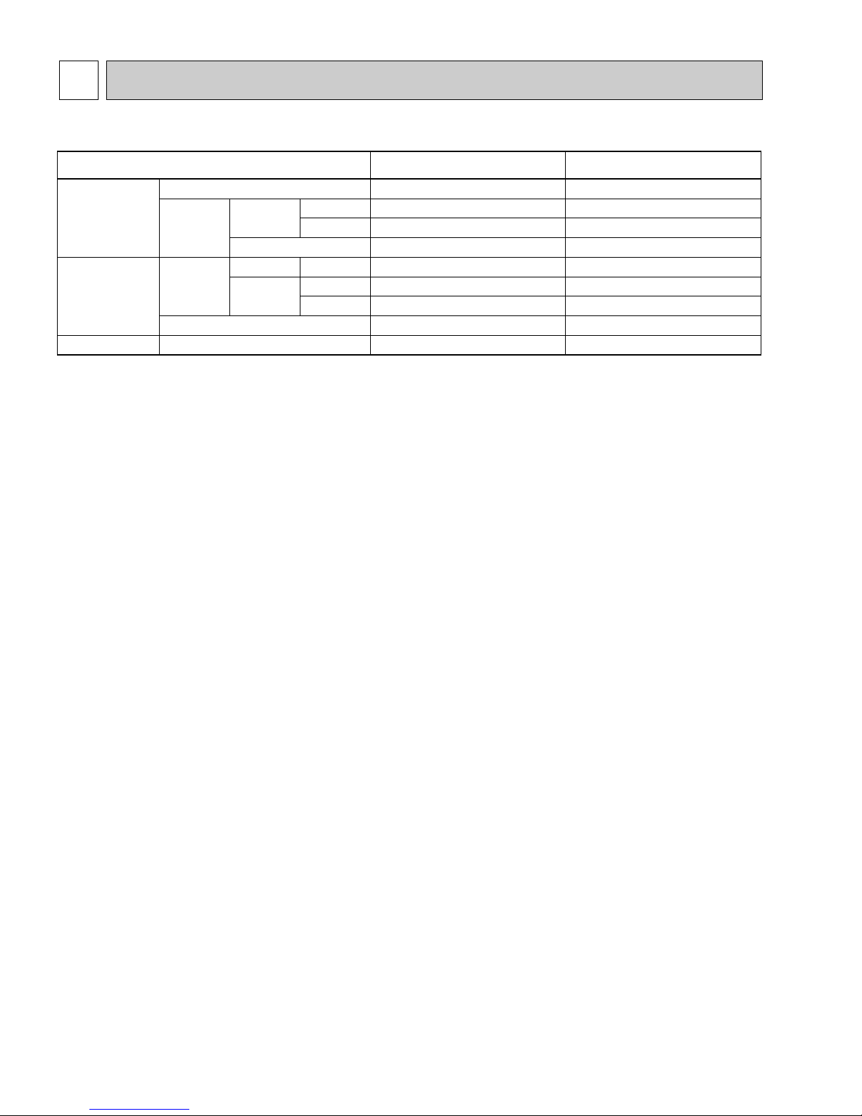
TECHNICAL CHANGE
Change points
Optional parts
EK
Switch for temperature unit
Switch for louvers
—
OFF
—
—
—
PAC–SK65PT
Canceled
Canceled
Addition of "Mode selector"
ON
Addition of "Not yet used"
Addition of "LOSSNAY interlocked or not"
Addition of "CN2L"
PAC–SK32PTA
EK
1
SW17
SW18
SW1
SW5
Connector for LOSSNAY interlocked
Program timer
No.9
No.0
No.10
No.3
No.4
Dip switch
Dip switch
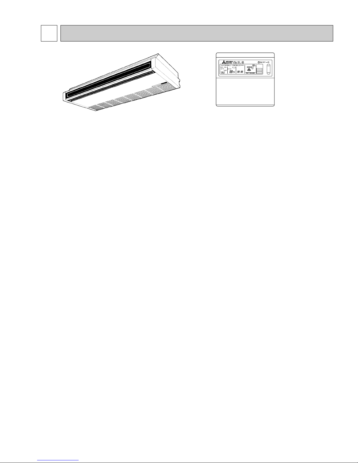
Appearances
Remote
controller
Indoor controller
4-
3
/4 o 2-3/4 o 5/8 5-1/8 o 4-3/4 o 3/4
Differences with OC002 which is a basic service manual.
OC193-3
FEATURES
2
1. ADVANCED MICROPROCESSOR CONTROL
(1) Easy to use Microprocessor (remote controller)
1) Ultra-Thin Remote Controller
The streamlined, square controller is designed to blend with any kind of interior and the adoption of a sophisticated
microprocessor allows you to carry out a wide range of operations easily.
2) Attractive Liquid Crystal Display (LCD)
Units operation mode, set temperature, room temperature, timer setting, fan speed, louver operation, and air flow direction are displayed on the remote controller with the easily understood visual Liquid Crystal Display (LCD).
3) Convenient 24-Hour ON-OFF Timer
The timer allows Mr.SLIM to be switched on and off automatically at the time you set. Once the timer is set, the remaining time is shown on the LCD.
4) Self-Diagnostic Feature Indicates Faults Instantly
In the rare case when a problem occurs, the unit stops operating and the set temperature indicator changes to the selfdiagnostic indicator, indicating the location of the fault.
If the check switch is pressed twice, the unit stops operating and the check mode is initiated. The cause of the most
recent problem stored in the memory is displayed on the LCD. This is extremely useful for maintenance purposes.
5) Useful Memory Feature for Storing Instructions
The previous set value is memorized so that constant temperature control can be obtained. This is convenient when,
for example, a power failure occurs.
(2) Non-polar Two-Wire Remote Controller Cables
The non-polar, two-wire type remote controller cable is slim, installation is simple and trouble-free. Remote controller wire
can be extended up to 550 yards.
(3) Automatic Cooling/Heating Changeover Operation
An automatic cooling and heating changeover operation system is provided to ensure easy control and year-round air conditioning.
Once the desired temperature is set, unit operation is switched automatically between cooling and heating, in accordance
with the room temperature. In addition, the use of outdoor unit fan speed controller enables cooling operation at outdoor
temperature as low as 23-F .
2. INNOVATIVE SYSTEM CONTROL BY MICROPROCESSORS
The most significant feature of the series PCH-EK is the advanced microprocessor system control. Behind the development
of this system is the recent world-wide trend in the air conditioning of larger buildings, away from centralized duct systems in
favor of a large number of individual split type units. There are a number of reasons for this: first, costly, troublesome duct
installation is eliminated; second, the overall air conditioning balance is excellent; and third, operation cost is low since flexible control of each unit is possible. This system control was developed exclusively by Mitsubishi in the light of this demand.
Microprocessor control makes possible individual control, group control, control using two remote controllers, remote on/off
control and individual control without troublesome modifications to the equipment.
(1) Individual Control by Gathering Remote Controllers
A Series PCH-FK unit is installed in each room, and the remote controller are gathered together in separate location, where
each unit is controlled individually.
Each remote controller is connected to its indoor unit by non-polar 2-wire cable to eliminate the possibility of mis-wiring.
Separation can be as much as 550 yards, making this type of control extremely easy to implement. Thermistors in the
indoor unit maintain each room at its own individually set temperature.
Models Cooling capacity / Heating capacity SEER
PCH24EK1 24,000 / 27,000 (33,500) Btu/h 10.3
PCH30EK1 30,000 / 33,000 (41,500) Btu/h 10.0
PCH36EK
1 35,400 / 38,000 (47,600) Btu/h 10.4
PCH42EK
1 42,000 / 45,000 (54,600) Btu/h 10.0
PCH24EK
Indoor Unit
Microprocessor
Remote controller
FILTER
CHECK MODE
TEST RUN
TIMER OFF TIMER
CHECK SET TEMP.
CLOCK AUTO AUTO
START STOP
SWING
FAN
SPEED
AUTO
RETURN
OC193-4
(2) Group Control by a Single Remote Controller
In an application requiring a number of air conditioner units in a large area on a single floor, up to 50 units can be centrally
controlled using a single remote controller. The remote controller controls Power ON-OFF, set temperature, fan speed,
swing louver ON-OFF timer, and auto vane position of all units of the group. Obviously, if all the units started simultaneously, the surge current would be unacceptably high. Therefore the microprocessor board of each indoor unit has a 8-toggle DIP switch that can be programmed to give sequential starting with up to 50 seconds delay. When the switch of the
remote controller is pressed, master unit comes on immediately, followed by the other units in the programmed order.
Thereafter the thermistor in each indoor unit controls compressor operation to keep the room at the set temperature.
The remote controller is connected to the indoor units by non-polar 2-wire cable. Total cable length can be as much as 550
yards. This system can be applied to the air conditioning of large offices or conference rooms, supermarkets, etc.
(3) Control Using Two Remote Controllers
Two remote controllers can be used to control either one unit or several units in group control. This makes it possible to
control units with ease either from a distance or at close range. Units operate according to the latest commands from either
remote controller.
(4) Both Remote ON/OFF Control and Individual Control
All units can be turned on and off simultaneously using the remote ON/OFF switch, and also individual units can be controlled from the remote controllers.
This system is well suited to buildings having a large number of rooms. In offices, for example, all units can be started
together to cool or heat the premises before workers arrive, operated as necessary by individual remote controllers during the day, and stopped together at the end of business.
3. REDI-CHARGED REFRIGERANT SYSTEM
When refrigerant tubing is 100ft or less, it is unnecessary to charge additional refrigerant. This can contribute to enhance
installation quality and reduce installation time.
4. MAXIMUM COMFORT AIR CONDITIONING
(1) Auto-Angle Airflow for Comfortable Air Conditioning
PCH units offer a choice of airflow outlets, a horizontal one and a downward-pointing one, and they incorporate auto-angle
vanes which can be used independently by means of microprocessor control. This has led to the development of a new
auto-angle airflow function and has made it possible to obtain the most comfortable forms of heating and cooling to suit
the requirements of all kinds of rooms.
When operating in the heating mode the vanes automatically set the downward direction of hot air at an angle of 70-.
When cooling, they are set at 0-so that 100% horizontal airflow is achieved. Altogether, four* directions of airflow can be
selected by remote control: 100% downward airflow, 80% downward airflow (plus 20% horizontal airflow), 60% downward
airflow (plus 40% horizontal airflow) and 100% horizontal airflow.
* When the fan speed is on low during cooling, only three types are available: 100% and 80% downward airflow and 100%
horizontal airflow.
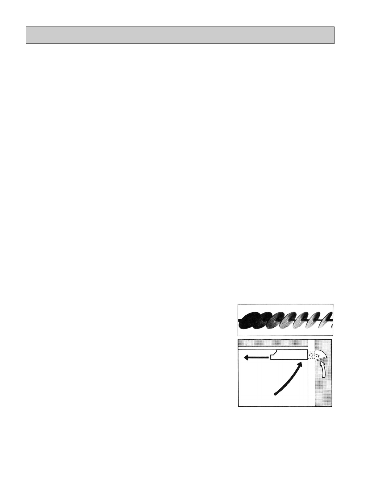
(2) Swing Flow Louvers
The swing Flow Louvers automatically change the air flow direction for desirable air distribution.
(3) Fresh-Air Intake
The PCH-EK series also has fresh air intake, providing more comfortable,
healthful air conditioning through better ventilation. The rear panel has a knockout for the intake of fresh air.
5. STABLE COOLING EVEN AT OUTDOOR TEMPERATURES AS LOW AS 23-F MAKES
YEAR-ROUND AIR-CONDITIONING POSSIBLE
The microprocessor automatically adjusts fan speed in accordance with outdoor temperature to maintain the coolant at an
even condensing temperature. The result is smooth, efficient cooling even when temperatures outdoors drop as low as 23F.
This makes the unit ideal for a wide range of specialized cooling needs, such as rooms with many office machines or com-

OC193-5
6. DRAIN PUMP FOR EASY PIPE CONNECTION (Option)
This mechanism, with its capacity to raise drain water 20” above the ceiling line, is convenient for removing water and avoiding piping contact with beams, etc.
Note : This can not be mounted in the unit.
7. SLIM, COMPACT AND SPACE SAVING
(1) Space Saving Design
Because the PCH-EK series indoor units are designed to be suspended from the ceiling, valuable floor space and wall
surfaces are not used. The unit is only 10-1/8” high and 50-7/16” wide (PCH24/30EK).
The outdoor units are also slim line, with a depth dimension of only 11-5/8” (PUH-24EK).
(2) Flush-To-The-Wall Installation
Since the units in the PCH-EK series are installed flush against the back wall, connection pipes are hidden. This gives the
room a touch of sleek sophistication.
8. EASY INSTALLATION
Installation is simple, thanks to the easy-connection refrigerant lines.
The indoor unit is easy to mount and requires only a minimum of wiring, saving your time, labor, and money.
9. HIGH RELIABILITY AND EASY SERVICING
In addition to the self-diagnostic function, units are also equipped with a 3-minute time delay mechanism, an auto restart function, an emergency operation function, a test run switch, etc., to assure high reliability and easy servicing.
10. ECONOMICAL AND EFFICIENT OPERATION
• Mitsubishi exclusive LCD indicators show the temperature selected and the current room temperature. This system ensures
full protection against excessive cooling.
• The Mitsubishi Electric split-type air-to-air PCH models feature highly precise compressors with large-capacity heat
exchangers for efficient operation.
11. NITROGEN GAS IS CHARGED TO INDOOR UNIT
Indoor unit and refrigerant pipes are charged with nitrogen gas (N
2) instead of (R22) before shipment from the factory.
OC193-6
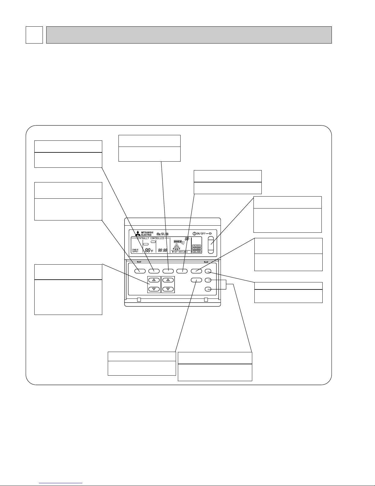
3 PART NAMES AND FUNCTIONS
Remote controller operation buttons
TIMER OFF TIMER
CHECK SET TEMP.
DRY COOL
AUTO
HEAT
CLOCK AUTO AUTO
START STOP
MODE TIMER ON/OFF CLOCK/TIMER FAN SPEED AIR DISCHARGE FILTER
CHECK
TEST RUN
AIR SWEEP
SET TEMP. TIMER SET
F
FAN
SPEED
AUTO
RETURN
REMOTE CONTROLLER
PAR-JH250KUS
FILTER button
This resets the filter service indication display.
TIMER ON/OFF button
This switches between continuous
operation and the timer operation.
SET TEMPERATURE
button
This sets the room temperature.
The temperature setting can be per-
formed in 2-F units.
Setting range :
Cooling 65-F to 87-F
Heating 61-F to 83-F
CHECK-TEST RUN button
Only press this button to perform an
inspection check or test operation.
Do not use it for normal operation.
AIR SWEEP button
This switches the horizontal fan
motion (Swing louver) ON and OFF.
CLOCK/TIMER button
This sets or switches the current
time,start time and stop time.
FAN SPEED button
This sets the ventilation fan speed.
AIR DISCHARGE
button
This adjusts the vertical angle of the
ventilation.
ON/OFF button
This switches between the operation and stop modes each time it is
press. The lamp on this button
lights during operation.
OPERATION MODE
button
Press this button to switch the cool-
ing, electronic dry (Dehumidify),
automatic and heating modes.
Remote controller
Once the controls are set, the same operation mode can be repeated by simply pressing the
ON / OFF button.

OC193-7
Operation lamp
This lamp lights during operation,
goes off when the unit stops and
flashes when a malfunction occurs.
CENTRALLY
CONTROLLED display
This indicates when the unit is con-
trolled by optional features such as
central control type remote controller.
TIMER display
This indicates when the continuous
operation and time operation modes
are set.
It also display the time for the timer
operation at the same time as when
it is set.
OPERATION MODE display
This indicates the operation mode.
STANDBY display
This indicates when the standby
mode is set from the time the heat
operation starts until the heating air
is discharged.
DEFROST display
This indicates when the defrost oper-
ation is performed.
CHECK display
This indicates when a malfunction
has occurred in the unit which should
be checked.
display
This lamp lights when electricity is
supplied to the unit.
display
This displays the selected setting
temperature.
F
CLOCK display
The current time , start time and stop
time can be displayed in ten second
intervals by pressing the time switch
button. The start time or stop time is
always displayed during the timer
operation.
AIR DISCHARGE display
This displays the air direction.
display
The temperature of the return air is
displayed during operation. The display range is 47°F to 97°F. The display flashes 47°F when the actual
temperature is less than 47°F and
flashes 97°F when the actual temperature is greater than 97°F.
F
In this display example on the bottom left, a condition where all display lamps light is shown for
explanation purposes although this differs from
actual operation.
display
This display lights in the check mode
or when a test operation is performed.
CHECK MODE
TEST RUN
display
This lamp lights when the filter needs
to be cleaned.
FAN SPEED display
The selected fan speed is displayed.
Caution
Only the display lights when the unit is stopped and power supplied to the unit.
When power is turned ON for the first time the (CENTRAL CTRL) display appears to go off momentarily but this is not a malfunction.
When the central control remote control unit, which is sold separately, is used the ON-OFF button,OPERATION MODE button and SET
TEMP. button do not operate.
FILTER
Remote controller display
TIMER OFF TIMER
DRY COOL
AUTO
HEAT
MODE TIMER ON/OFF CLOCK/TIMER FAN SPEED AIR DISCHARGE FILTER
REMOTE CONTROLLER
PAR-JH250KUS
CLOCK AUTO AUTO
CHECK SET TEMP.
START STOP
SET TEMP. TIMER SET
AUTO
RETURN
F
AIR SWEEP
CHECK
TEST RUN
FAN
SPEED
OC193-8
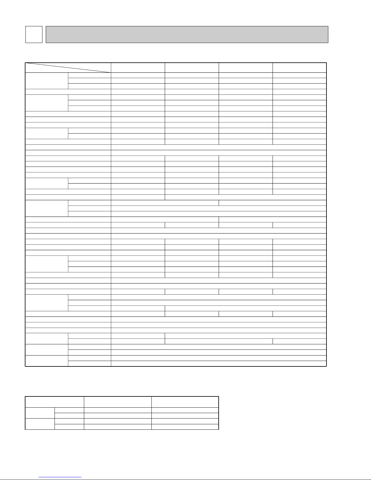
4 SPECIFICATIONS
Capacity
Moisture removal
Power
Consumption
EER
SEER
HSPF
COP
INDOOR UNIT MODELS
External finish
Power supply
Max.fuse size (time delay)
Min.ampacity
Fan motor
Booster heater
Airflow Hi-Lo
Sound level Hi-Lo
Unit drain pipe O.D.
Dimensions
Weight
OUTDOOR UNIT MODELS
External finish
Power supply
Max.fuse size (time delay)
Min.ampacity
Fan motor
Compressor
Crankcase heater
Refrigerant control
Defrost method
Sound level
Dimensions
Weight
REMOTE CONTROLLER
Control voltage (by built-in transformer)
REFRIGERANT PIPING
Pipe size
Connection
method
Between the indoor
& outdoor units
Cooling *1
Heating *1
Heating *2
Cooling *1
Heating *1
Heating *2
*1
*1
*2
Dry
Wet
W
D
H
Model (type)
W
D
H
Liquid
Gas
Indoors
Outdoors
Height difference
Piping length
Btu/h
Btu/h
Btu/h
Pints/h
kW
kW
kW
V,phase,Hz
A
A
F.L.A.
A(kW
)
CFM
CFM
dB
in.
in.
in.
in.
lb
V,phase,Hz
A
A
F.L.A.
R.L.A.
L.R.A.
A(W
)
dB
in.
in.
in.
lb
in.
in.
ft
ft
PCH24EK
1
Model
24,000
27,000[32,500/33,500]
18,400[23,900/24,900]
7.0
2.46
2.42[4.02/4.32]
2.1[3.7/4.0]
9.8
10.3
7.1
3.3
2.6
PCH24EK1
20
12
0.7
7.6/8.4<1.6/1.9>
920-740
830-670
50-43
1
PUH-24EK
20
16
0.65+0.65
NH33NBD
11.5
54
0.16/0.17<33/39>
55
34-1/4
11-5/8
49-9/16
202
3/8
5/8
PCH30EK
1
30,000
33,000[39,800/41,500]
18,000[24,800/26,500]
9.1
3.06
3.13[5.13/5.63]
2.6[4.6/5.1]
9.8
10.0
7.1
3.1
2.4
PCH30EK1
25
15
0.7
9.8/10.8<2.0/2.5>
920-740
830-670
50-43
1
PUH30EK
30
20
0.75+0.75
NH41NAD
14.0
73
0.16/0.17<33/39>
55
245
Munsell 2.5Y 8/0.3 & N2
208/230,1,60
26-13/16
10-1/8
Munsell 5Y 7/1
208/230,1,60
Capillary tube
Reverse cycle
With indoor unit
Indoor unit-remote controller: DC12V. Indoor unit-outdoor unit: DC12V
Not supplied (optional parts)
3/4
Flared
Flared
164
165
PCH36EK
1
35,400
38,000[45,900/47,600]
19,600[27,500/29,200]
10.9
3.53
3.4[5.7/6.2]
2.7[5.0/5.5]
10.0
10.4
7.4
3.3
2.1
PCH36EK1
25
15
1.3
10.8/12.0<2.3/2.8>
1,270-990
1,100-860
51-45
1
PUH36EK
1
30
22
0.75+0.75
NH47NAD
17.5
87
0.16/0.17<33/39>
55
38-3/16
13-9/16
49-9/16
246
1/2
PCH42EK
1
42,000
45,000[52,900/54,600]
24,800[32,700/34,400]
12.3
4.37
4.3[6.6/7.1]
3.2[5.5/6.0]
9.6
10.0
7.3
3.1
2.3
PCH42EK1
25
17
1.3
10.8/12.0<2.3/2.8>
1,270-990
1,100-860
51-45
1
PUH42EK
1
40
27
0.8+0.8
NH569NXA
20.0
105
0.16/0.17<33/39>
56
268
7/8
Item
50-7/16
101
62-1/4
119
NOTES : *1.Rating conditions (cooling)-indoor : 80˚FDB,67˚FWB outdoor : 95˚FDB,75˚FWB.
(heating)-indoor: 70˚FDB,60˚FWB outdoor : 47˚FDB,43˚FWB.
*2.Rating conditions (heating)-indoor: 70˚FDB,60˚FWB outdoor : 17˚FDB,15˚FWB.
*3.Heating capacity and power consumption in [ ] includes booster heater operation at 208/230V.
Operating range
Indoor intake air temperature
95˚FDB,71˚FWB
67˚FDB,57˚FWB
80˚FDB,67˚FWB
70˚FDB,68˚FWB
Outdoor intake air temperature
115˚FDB
0˚FDB *
75˚FDB,65˚FWB
17˚FDB,15˚FWB
Cooling
Heating
Maximum
Minimum
Maximum
Minimum
*
In case of the wind baffle is installed.
(In case of the wind baffle is not installed, the minimum temperature will be 23˚FDB.)
MODELS : PCH24/30/36/42EK1
OC193-9
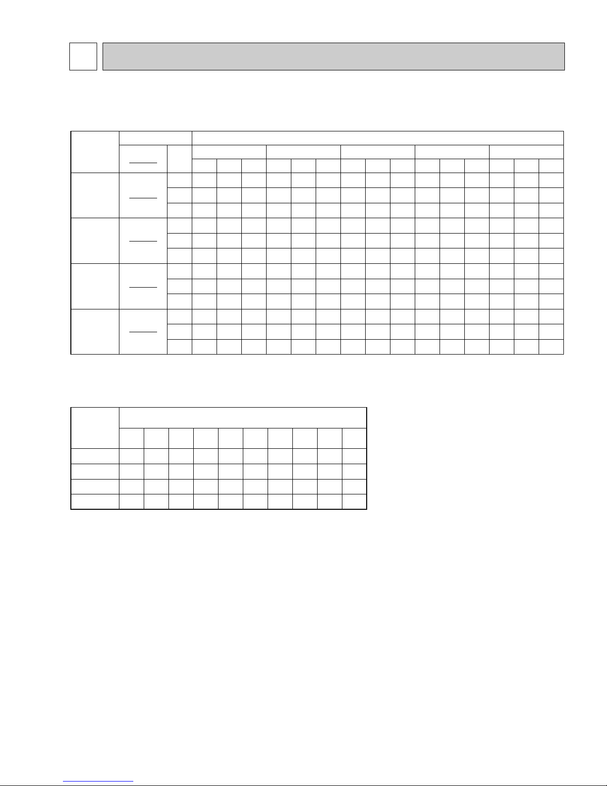
DATA5
Models
Models Outdoor intake air DB temperature(˚F
)
PCH24EK
1
71
67
63
71
67
63
71
67
63
71
67
63
TC
28.4
26.3
24.5
34.7
32.5
30.2
40.9
38.1
35.7
49.6
46.0
42.9
SHC
16.1
18.6
20.5
17.8
21.2
23.6
21.1
24.9
2.80
23.8
28.4
32.1
TPC
2.15
2.10
2.00
2.69
2.62
2.55
3.02
2.95
2.88
3.99
3.86
3.73
TC
27.1
25.1
24.5
33.5
31.4
29.2
39.7
36.7
34.5
47.6
44.2
41.1
SHC
15.8
18.2
20.1
17.5
20.7
23.1
20.8
24.3
27.4
23.1
27.6
31.1
TPC
2.34
2.29
2.18
2.91
2.84
2.76
3.28
3.23
3.15
4.24
4.09
3.94
TC
25.7
24.0
22.2
32.1
30.0
28.0
38.1
35.4
33.1
45.4
42.0
39.3
SHC
15.4
17.8
19.4
17.1
20.2
22.4
20.3
23.8
26.6
22.6
26.7
30.1
TPC
2.53
2.46
2.38
3.17
3.06
3.02
3.60
3.53
3.43
4.54
4.37
4.19
TC
24.3
22.7
21.0
30.8
28.8
26.8
36.3
33.7
31.6
43.1
39.9
37.1
SHC
15.1
17.3
18.8
16.8
19.7
21.8
19.9
23.1
25.8
21.9
25.8
28.9
TPC
2.74
2.67
2.56
3.46
3.36
3.28
3.95
3.85
3.74
4.84
4.64
4.44
TC
22.7
21.0
19.8
29.2
27.4
25.4
34.5
32.1
30.2
40.7
37.7
34.7
SHC
14.8
16.6
18.3
16.3
19.1
21.1
19.4
22.5
25.1
21.3
24.9
27.5
TPC
2.95
2.87
2.76
3.73
3.63
3.54
4.30
4.18
4.05
5.20
4.95
4.74
IWB
(˚F)
75 85 95 105 115
900
0.13
Airflow
(
CFM
)
B.F
PCH30EK1
900
0.10
PCH36EK1
1,100
0.13
PCH42EK1
1,100
0.11
Notes 1. B.F. : Bypass Factor, IWB : Intake air wet-bulb temperature
TC : Total Capacity (x10
3
Btu/h), SHC : Sensible Heat Capacity (x10
3
Btu/h)
TPC : Total Power Consumption (kW)
2. SHC is based on 80˚FDB of indoor intake air temperature.
3. Cooling capacity correction factors and Refrigerant piping length (one way) range.
MODEL
Refrigerant piping length (one way)
PCH24EK
1
PCH30EK1
PCH36EK1
PCH42EK1
1.0
1.0
1.0
1.0
25ft
0.981
0.981
0.981
0.975
40ft
0.968
0.986
0.968
0.955
55ft
0.952
0.952
0.952
0.935
70ft
0.940
0.940
0.940
0.918
85ft
0.925
0.925
0.925
0.900
100ft
0.913
0.913
0.913
0.884
115ft
0.900
0.900
0.900
0.869
130ft
0.886
0.886
0.886
0.855
150ft
0.874
0.874
0.874
0.840
164ft
MODELS : PCH24/30/36/42EK1
1. PERFORMANCE DATA
1) COOLING CAPACITY
OC193-10
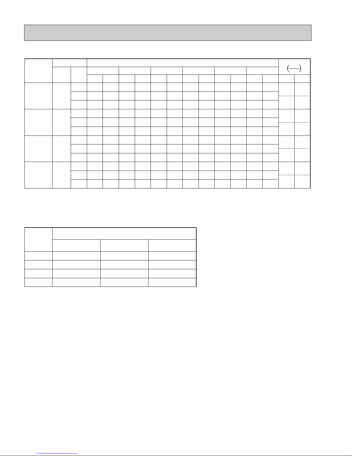
2) HEATING CAPACITY
Models
PCH24EK
PCH30EK
PCH36EK1
PCH42EK1
Notes 1. IDB : Intake air dry-bulb temperature
CA : Capacity (x10
2. When booster heater is "on", total capacity and total power consumption should be added the figures described in
booster heater column.
•Booster heater ON : When the set temperature is higher than the room temperature by more than 5.4 deg.
•Booster heater OFF : When the set temperature is higher than the room temperature by less than 3.6 deg.
3. Heating capacity correction factors.
Models Outdoor intake air WB temperature(˚F
Airflow
(CFM)
1
1
1,100
1,100
IDB
(˚F)
75
900
900
70
65
75
70
65
75
70
65
75
70
65
3
Btu/h), PC : Power Consumption (kW)
15 25 35 45 55 65
CA
PC
CA
PC
CA
PC
CA
18.7
2.19
21.1
2.29
23.9
2.42
27.5
19.1
2.09
21.3
2.19
24.3
2.29
27.9
19.5
1.98
21.6
2.03
24.7
2.16
28.6
22.2
2.54
25.4
2.70
29.0
3.03
32.9
22.6
2.37
26.2
2.59
29.8
2.87
33.7
23.0
2.26
26.6
2.48
30.4
2.76
34.5
25.8
2.75
29.6
3.05
33.7
3.35
38.3
26.2
2.63
30.4
2.90
34.5
3.15
39.1
26.8
2.48
31.0
2.75
35.3
3.05
40.5
26.6
3.41
32.5
3.67
39.1
4.03
45.6
26.8
3.38
32.9
3.62
39.7
3.96
46.4
27.0
3.33
33.3
3.56
40.1
3.88
47.2
PC
2.60
2.45
2.31
3.37
3.20
3.03
3.65
3.45
3.35
4.45
4.38
4.30
CA
31.2
32.1
33.0
37.3
38.1
38.9
43.3
44.0
45.2
53.2
54.0
55.2
)
PC
2.81
2.68
2.54
3.75
3.53
3.37
4.00
3.78
3.63
4.98
4.87
4.80
CA
36.3
36.9
37.6
41.3
42.1
43.5
47.8
48.8
50.6
60.9
61.9
63.5
PC
3.03
2.91
2.79
4.08
3.86
3.69
4.35
4.15
3.93
5.55
5.45
5.34
Auxiliary heater
208V
230V
PC
CA
1.6
5.5
1.9
6.5
2.0
6.8
2.5
8.5
2.3
7.9
2.8
9.6
2.3
7.9
2.8
9.6
Models
PCH24EK
PCH30EK1
PCH36EK1
PCH42EK1
1
Less than 100ft
1.00
1.00
1.00
1.00
Refrigerant piping length (one way)
100~130ft
0.995
0.995
0.995
0.995
130~164ft
0.990
0.990
0.990
0.990
OC193-11
Total power consumption (kW) Total capacity (x10
3
Btu/h)
Outdoor intake air WB temperature ( F)
54
42
30
18
4.0
3.0
2.0
1.0
65
70
75
75
70
65
Not include booster heater (2.5kW)
15 25 35 45 55 65
Indoor intake air DB temperature ( F)
Indoor intake air DB temperature ( F)
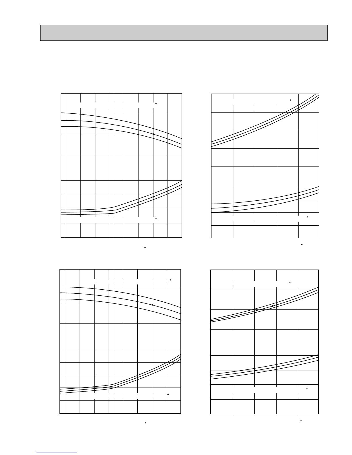
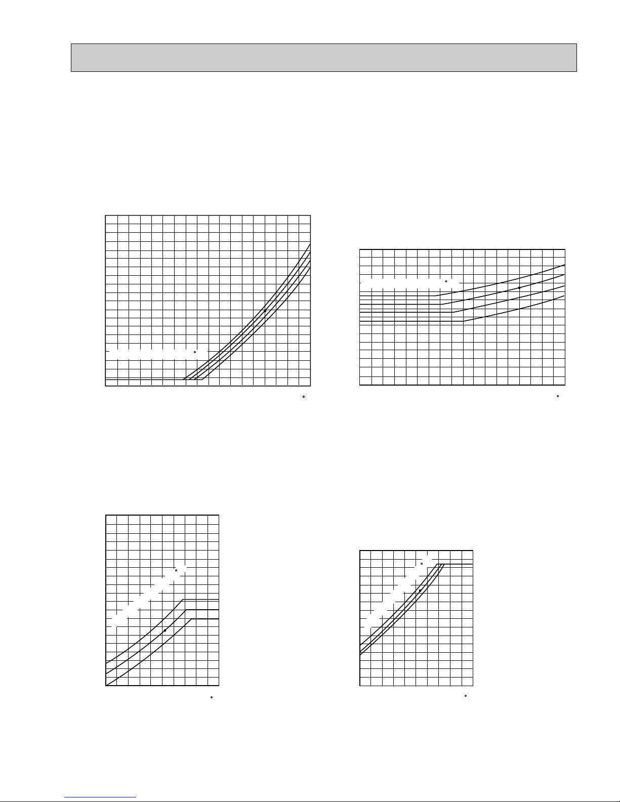
2. PERFORMANCE CURVE
NOTES : A point on the curve shows the reference point.
PCH24EK1 COOLING CAPACITY PCH24EK1 HEATING CAPACITY
PCH30EK
1 COOLING CAPACITY PCH30EK1 HEATING CAPACITY
Total power consumption (kW) Total capacity (x10
3
Btu/h)
Outdoor intake air DB temperature ( F)
36
30
24
18
3.0
2.5
2.0
1.5
63
67
71
63
67
71
SHF=0.73
32 35
45 55
65
(67)
75 85 95 105 115
Indoor intake air WB temperature ( F)
Indoor intake air WB temperature ( F)
Total power consumption (kW) Total capacity (x10
3
Btu/h)
Outdoor intake air WB temperature ( F)
36
30
24
18
12
3.0
2.5
2.0
1.5
65
70
75
75
70
65
Not include booster heater (1.9kW)
15 25 35 45 55 65
Indoor intake air DB temperature ( F)
Indoor intake air DB temperature ( F)
42
Btu/h)
3
36
30
Indoor intake air WB temperature ( F)
24
4.0
3.5
3.0
2.5
Indoor intake air WB temperature ( F)
2.0
Total power consumption (kW) Total capacity (x10
32 35
45 55
Outdoor intake air DB temperature ( F)
65
(67)
SHF=0.68
75 85 95 105 115
71
67
63
71
67
63
OC193-12
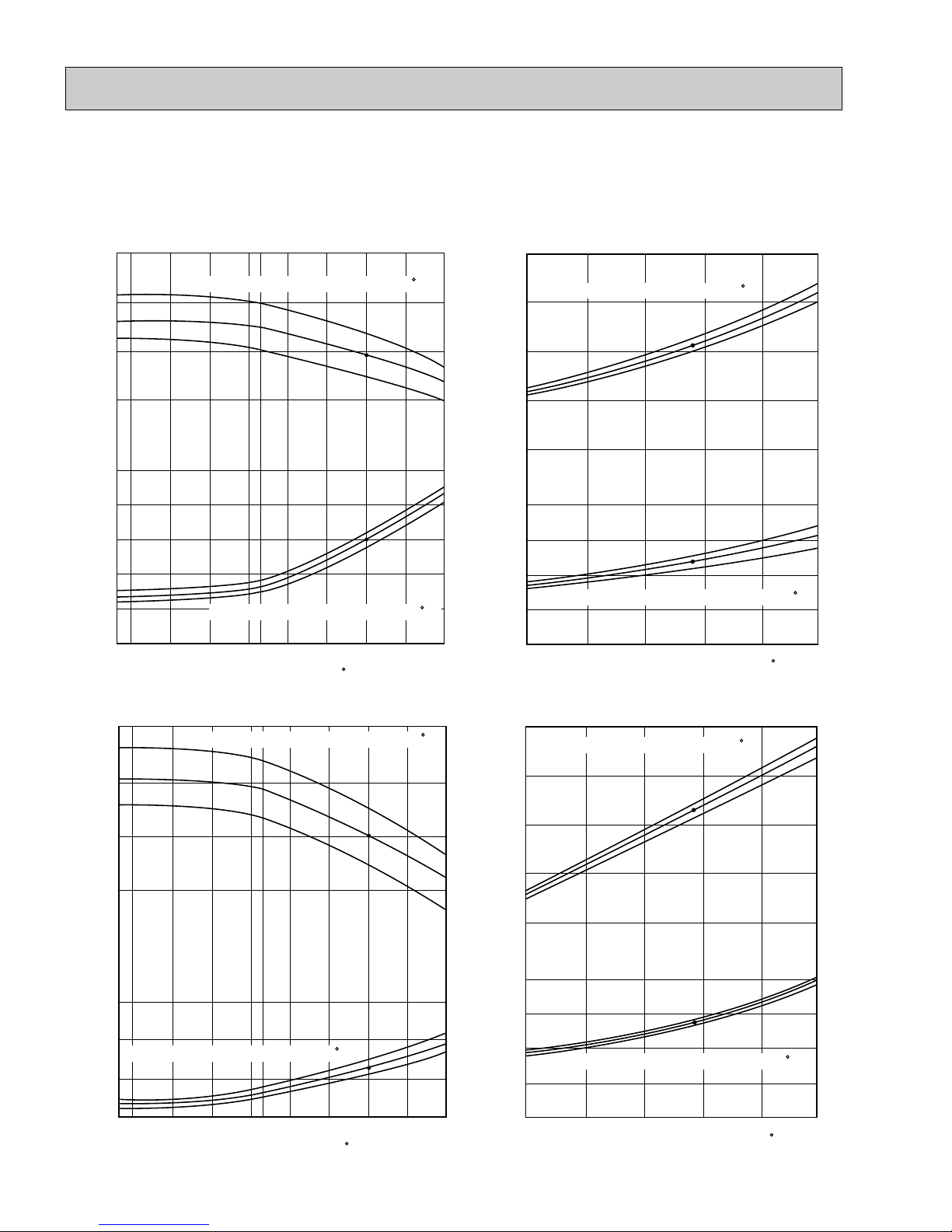
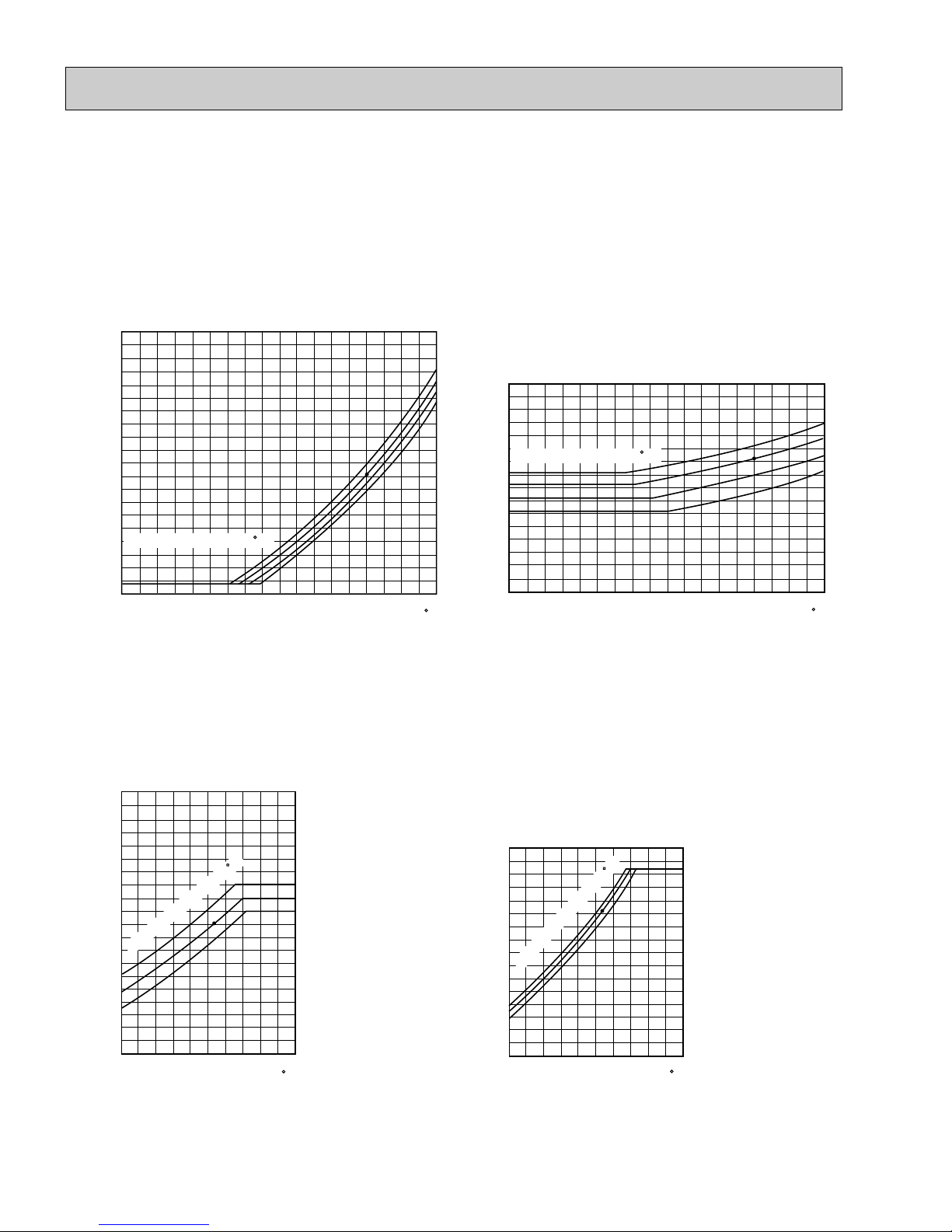
NOTES : A point on the curve shows the reference point.
PCH36EK1 COOLING CAPACITY PCH36EK1 HEATING CAPACITY
Total power consumption (kW) Total capacity (x10
3
Btu/h)
Outdoor intake air DB temperature ( F)
54
42
36
24
4.5
4.0
3.5
2.5
3.0
63
67
71
63
67
71
SHF=0.73
32 35
45 55
65
(67)
75 85 95 105 115
Indoor intake air WB temperature ( F)
Indoor intake air WB temperature ( F)
Total power consumption (kW) Total capacity (x10
3
Btu/h)
Outdoor intake air WB temperature ( F)
48
36
24
12
5.0
4.0
3.0
2.0
65
70
75
75
70
65
Not include booster heater (2.8kW)
15 25 35 45 55 65
Indoor intake air DB temperature ( F)
Indoor intake air DB temperature ( F)
Total power consumption (kW) Total capacity (x10
3
Btu/h)
Outdoor intake air DB temperature ( F)
54
48
42
36
4.0
6.0
5.0
63
67
71
63
67
71
SHF=0.67
32 35
45 55
65
(67)
75 85 95 105 115
Indoor intake air WB temperature ( F)
Indoor intake air WB temperature ( F)
Total power consumption (kW) Total capacity (x10
3
Btu/h)
Outdoor intake air WB temperature ( F)
66
54
42
30
18
5.5
4.5
3.5
2.5
65
70
75
75
70
65
Not include booster heater (2.8kW)
15 25 35 45 55 65
Indoor intake air DB temperature ( F)
Indoor intake air DB temperature ( F)
PCH42EK1
COOLING CAPACITY PCH42EK1HEATING CAPACITY
OC193-13
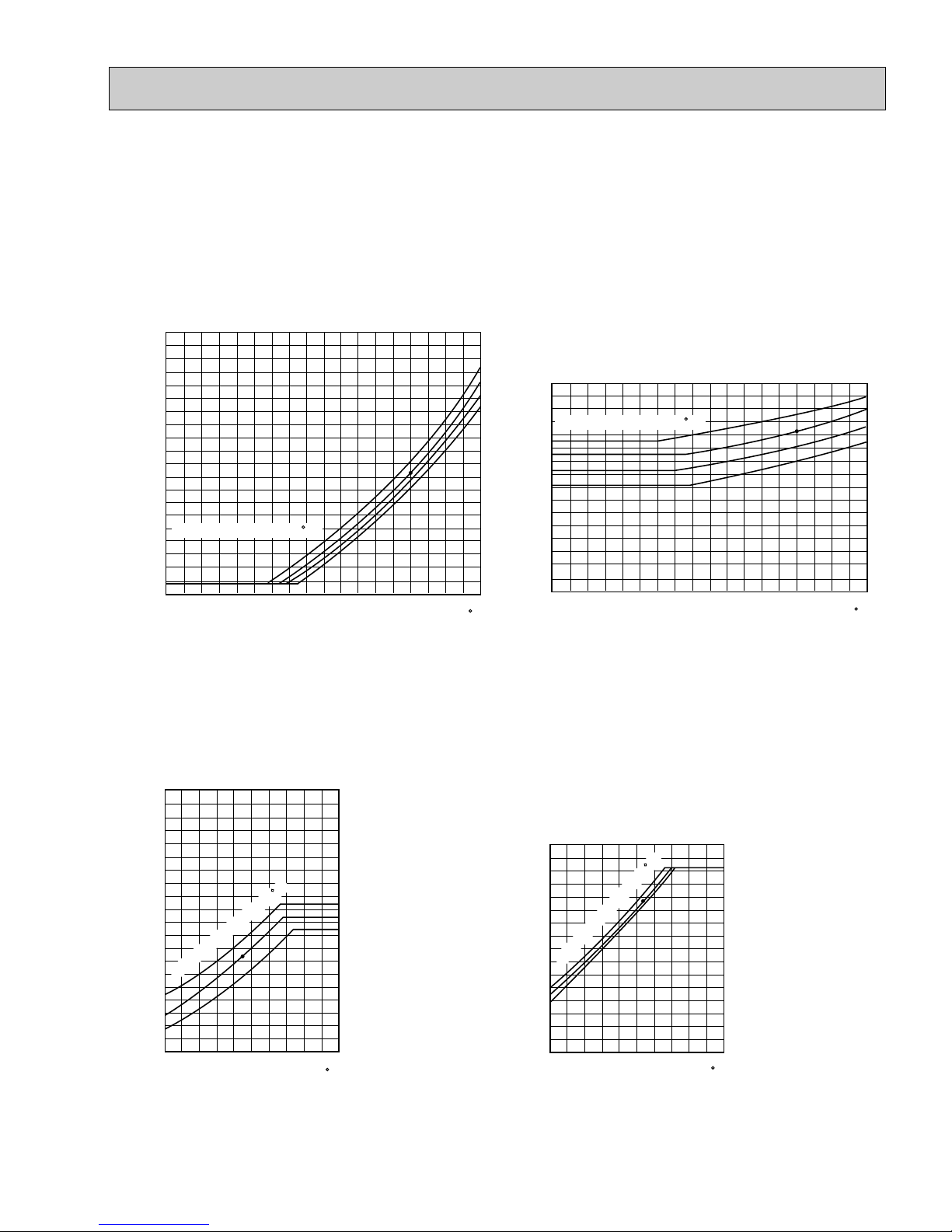
3. CONDENSING PRESSURE AND SUCTION PRESSURE
Data is based on the condition of indoor humidity 50%.
Air flow should be set at HI.
A point on the curve shows the reference point.
< Cooling mode>
Data is based on the condition of outdoor humidity 75%.
A point on the curve shows the reference point.
< Heating mode>
350
340
330
320
310
300
290
280
270
260
250
240
230
220
210
200
190
180
170
160
150
(psi.G)
Condensing pressure
30 40 50 60 70 80 90 100 110
Outdoor ambient temperature
DB( F)
Indoor DB temperature( F)
86
80
75
70
100
90
80
70
60
50
40
30
20
(psi.G)
Suction pressure
30 40 50 60 70 80 90 100 110
Outdoor ambient temperature
DB( F)
Indoor DB temperature( F)
86
80
75
70
350
340
330
320
310
300
290
280
270
260
250
240
230
220
210
200
190
180
170
160
150
(psi.G)
Condensing pressure
30 3520 25 45 55 6540 50 60 70
Outdoor ambient temperature
DB( F)
75
70
65
Indoor DB temperature( F)
80
70
60
50
40
30
20
10
(psi.G)
Suction pressure
30 3520 25 45 55 6540 50 60 70
Outdoor ambient temperature
DB( F)
75
70
65
Indoor DB temperature( F)
PCH24EK1
PCH24EK1
PCH24EK1
PCH24EK1
OC193-14
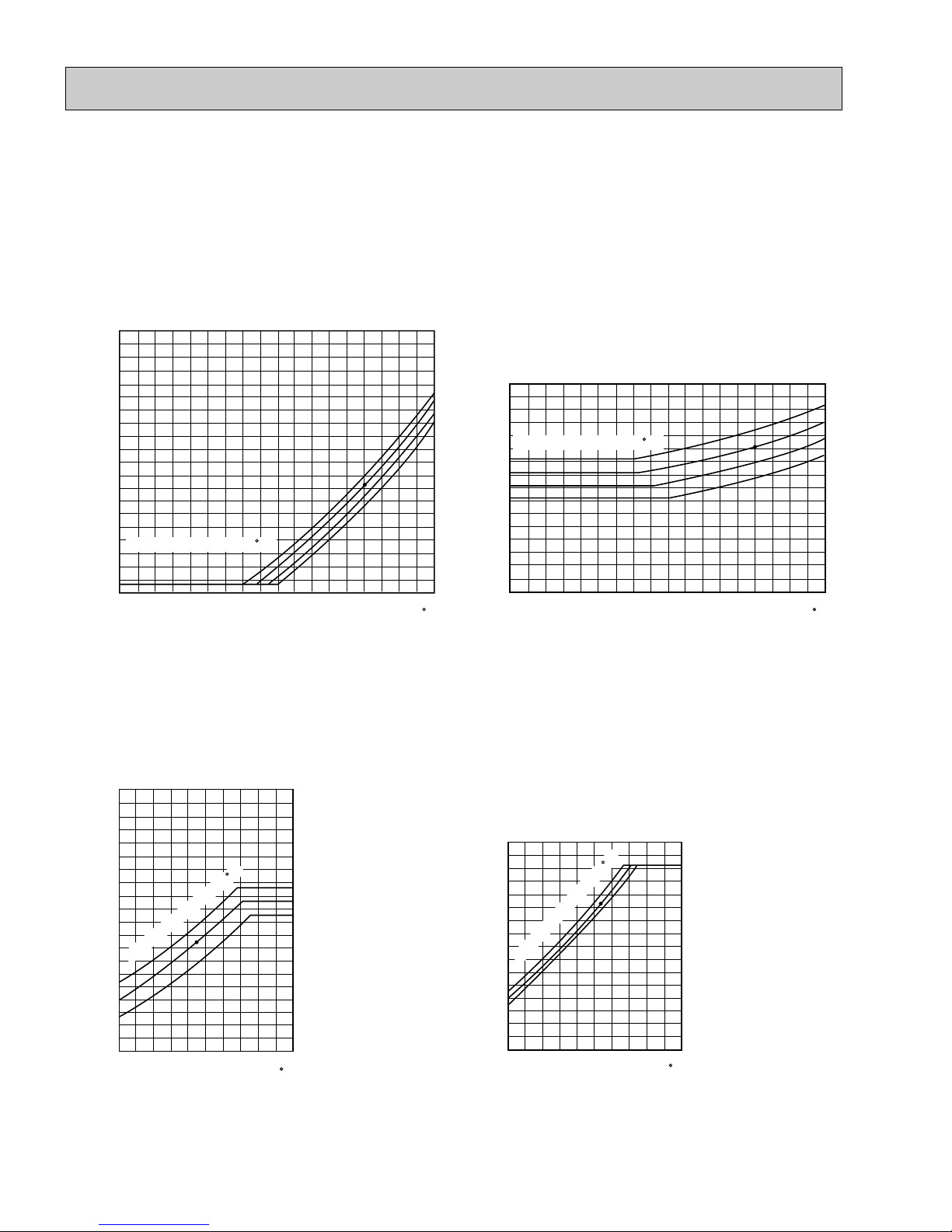
Data is based on the condition of indoor humidity 50%.
Air flow should be set at HI.
A point on the curve shows the reference point.
< Cooling mode>
Data is based on the condition of outdoor humidity 75%.
A point on the curve shows the reference point.
< Heating mode>
350
340
330
320
310
300
290
280
270
260
250
240
230
220
210
200
190
180
170
160
150
(psi.G)
Condensing pressure
30 40 50 60 70 80 90 100 110
Outdoor ambient temperature
DB( F)
Indoor DB temperature( F)
86
80
75
70
100
90
80
70
60
50
40
30
20
(psi.G)
Suction pressure
30 40 50 60 70 80 90 100 110
Outdoor ambient temperature
DB( F)
Indoor DB temperature( F)
86
80
75
70
350
340
330
320
310
300
290
280
270
260
250
240
230
220
210
200
190
180
170
160
150
(psi.G)
Condensing pressure
30 3520 25 45 55 6540 50 60 70
Outdoor ambient temperature
DB( F)
75
70
65
Indoor DB temperature( F)
80
70
60
50
40
30
20
10
(psi.G)
Suction pressure
30 3520 25 45 55 6540 50 60 70
Outdoor ambient temperature
DB( F)
75
70
65
Indoor DB temperature( F)
PCH30EK1
PCH30EK1
PCH30EK1
PCH30EK1
OC193-15
Data is based on the condition of indoor humidity 50%.
Air flow should be set at HI.
A point on the curve shows the reference point.
< Cooling mode>
Data is based on the condition of outdoor humidity 75%.
A point on the curve shows the reference point.
< Heating mode>
350
340
330
320
310
300
290
280
270
260
250
240
230
220
210
200
190
180
170
160
150
(psi.G)
Condensing pressure
30 40 50 60 70 80 90 100 110
Outdoor ambient temperature
DB( F)
Indoor DB temperature( F)
86
80
75
70
100
90
80
70
60
50
40
30
20
(psi.G)
Suction pressure
30 40 50 60 70 80 90 100 110
Outdoor ambient temperature
DB( F)
Indoor DB temperature( F)
86
80
75
70
350
340
330
320
310
300
290
280
270
260
250
240
230
220
210
200
190
180
170
160
150
(psi.G)
Condensing pressure
30 3520 25 45 55 6540 50 60 70
Outdoor ambient temperature
DB( F)
75
70
65
Indoor DB temperature( F)
80
70
60
50
40
30
20
10
(psi.G)
Suction pressure
30 3520 25 45 55 6540 50 60 70
Outdoor ambient temperature
DB( F)
75
70
65
Indoor DB temperature( F)
PCH36EK1
PCH36EK1
PCH36EK1
PCH36EK1
OC193-16
Data is based on the condition of indoor humidity 50%.
Air flow should be set at HI.
A point on the curve shows the reference point.
< Cooling mode>
Data is based on the condition of outdoor humidity 75%.
A point on the curve shows the reference point.
< Heating mode>
350
340
330
320
310
300
290
280
270
260
250
240
230
220
210
200
190
180
170
160
150
(psi.G)
Condensing pressure
30 40 50 60 70 80 90 100 110
Outdoor ambient temperature
DB( F)
Indoor DB temperature( F)
86
80
75
70
100
90
80
70
60
50
40
30
20
(psi.G)
Suction pressure
30 40 50 60 70 80 90 100 110
Outdoor ambient temperature
DB( F)
Indoor DB temperature( F)
86
80
75
70
350
340
330
320
310
300
290
280
270
260
250
240
230
220
210
200
190
180
170
160
150
(psi.G)
Condensing pressure
30 3520 25 45 55 6540 50 60 70
Outdoor ambient temperature
DB( F)
75
70
65
Indoor DB temperature( F)
80
70
60
50
40
30
20
10
(psi.G)
Suction pressure
30 3520 25 45 55 6540 50 60 70
Outdoor ambient temperature
DB( F)
75
70
65
Indoor DB temperature( F)
PCH42EK1
PCH42EK1
PCH42EK1
PCH42EK1
OC193-17
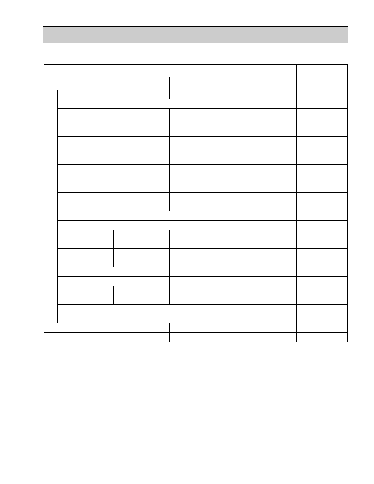
4. STANDARD OPERATION DATA
Models
Item
Electrical circuitRefrigerant circuitIndoor sideOutdoor side
Voltage
Frequency
Total input
Indoor fan current
Booster heater current
Outdoor fan current
Comp. current
Condensing pressure
Suction pressure
Discharge temperature
Condensing temperature
Suction temperature
Comp.shell bottom temperature
Ref. pipe length
Refrigerant charge
Fan speed
Airflow (High)
Fan speed upper/lower
Airflow
Unit
V
Hz
kW
A
A
A
A
psi.G
psi.G
˚F
˚F
˚F
˚F
ft
˚F
˚F
˚F
˚F
r.p.m.
CFM
˚F
˚F
r.p.m.
CFM
Btu/h
208/230
2.46
0.7
0.65+0.65
11.3/10.4
245
81
176
116
58
165
80
67
59
57
1,485
830
95
24,000
0.73
60
Cooling
208/230
2.42
0.7
7.6/8.4
0.65+0.65
10.9/10.2
236
60
168
113
35
153
70
60
98
1,470
920
47
43
27,000
Heating
PCH24EK
1
208/230
3.06
0.7
0.75+0.75
14.0/13.3
232
76
158
112
48
149
80
67
55
54
1,485
830
95
30,000
0.68
60
Cooling
208/230
3.13
0.7
9.8/10.8
0.75+0.75
14.3/13.5
243
58
168
115
35
156
70
60
105
1,470
920
47
43
33,000
Heating
PCH30EK
1
208/230
3.53
1.3
0.75+0.75
16.1/14.3
235
77
164
113
48
154
80
67
58
57
1,505
1,100
95
35,400
0.73
60
Cooling
208/230
3.4
1.3
10.8/12.0
0.75+0.75
14.7/14.0
216
58
160
107
34
149
70
60
100
1,480
1,270
47
43
38,000
Heating
PCH36EK
1
208/230
4.37
1.3
0.8+0.8
21.0/19.1
240
71
181
114
51
171
80
67
55
54
1,505
1,100
95
42,000
0.67
60
25
9 lbs 15 oz
750/750
3,170
760/760
3,350
760/760
3,350
840/840
3,530
25
10 lbs 2 oz
25
10 lbs 9 oz
25
12 lbs 9 oz
Cooling
208/230
4.3
1.3
10.8/12.0
0.8+0.8
19.5/18.7
252
56
175
118
33
160
70
60
106
1,480
1,270
47
43
45,000
Heating
PCH42EK
1
Intake
air temperature
Discharge
air temperature
Intake
air temperature
Capacity
SHF
DB
WB
DB
WB
DB
WB

OC193-18
5. OPERATING RANGE
1) POWER SUPPLY
6. OUTLET AIR SPEED AND COVERAGE RANGE
7. ADDITIONAL REFRIGERANT CHARGE (R22(oz))
1 Phase 60Hz 208/230V
Guaranteed voltage range
2) OPERATION
Min. Max.
198V 208V 230V 253V
The air coverage range is the value up to the position
where the air speed is 0.8ft/sec. when air is blown out
horizontally from the unit at the High notch position.
The coverage range should be used only as a general
guideline since it varies according to the size of the
room and furniture installed inside the room.
Function
Condition
Air intake temperature
DB(˚F
)
Indoor
WB(˚F
Outdoor
)
DB(˚F
)
WB(˚F
)
Cooling
Heating
Standard temperature
Maximum temperature
Minimum temperature
Maximum humidity
Standard temperature
Maximum temperature
Minimum temperature
80
95
67
80
70
80
70
Model
PCH24EK
PCH30EK1
PCH36EK1
PCH42EK1
Airflow
(
)
CFM
1
920
920
1,270
1,270
Air speed
(
ft/sec
15.0
15.0
16.5
16.5
)
Coverage
range(ft
38
38
48
48
)
Refrigerant piping length (one way)
55ft
70ft
85ft
100ft
Model
Outdoor unit
precharged
(
up to 100ft
)
25ft
40ft
67
71
57
75
60
67
60
95
115
23
80
47
75
17
75
—
—
75
43
65
15
115ft
130ft
150ft
164ft
0
PCH24EK
PCH30EK1
PCH36EK1
PCH42EK1
1
9 lbs 15 oz
10 lbs 2 oz
10 lbs 9 oz
12 lbs 9 oz
0
0
0
0
0
0
0
0
0
0
0
2
4
7
9
0
0
0
0
5
10
16
20
0
0
0
0
5
10
16
20
0
0
0
0
5
10
16
20
OC193-19
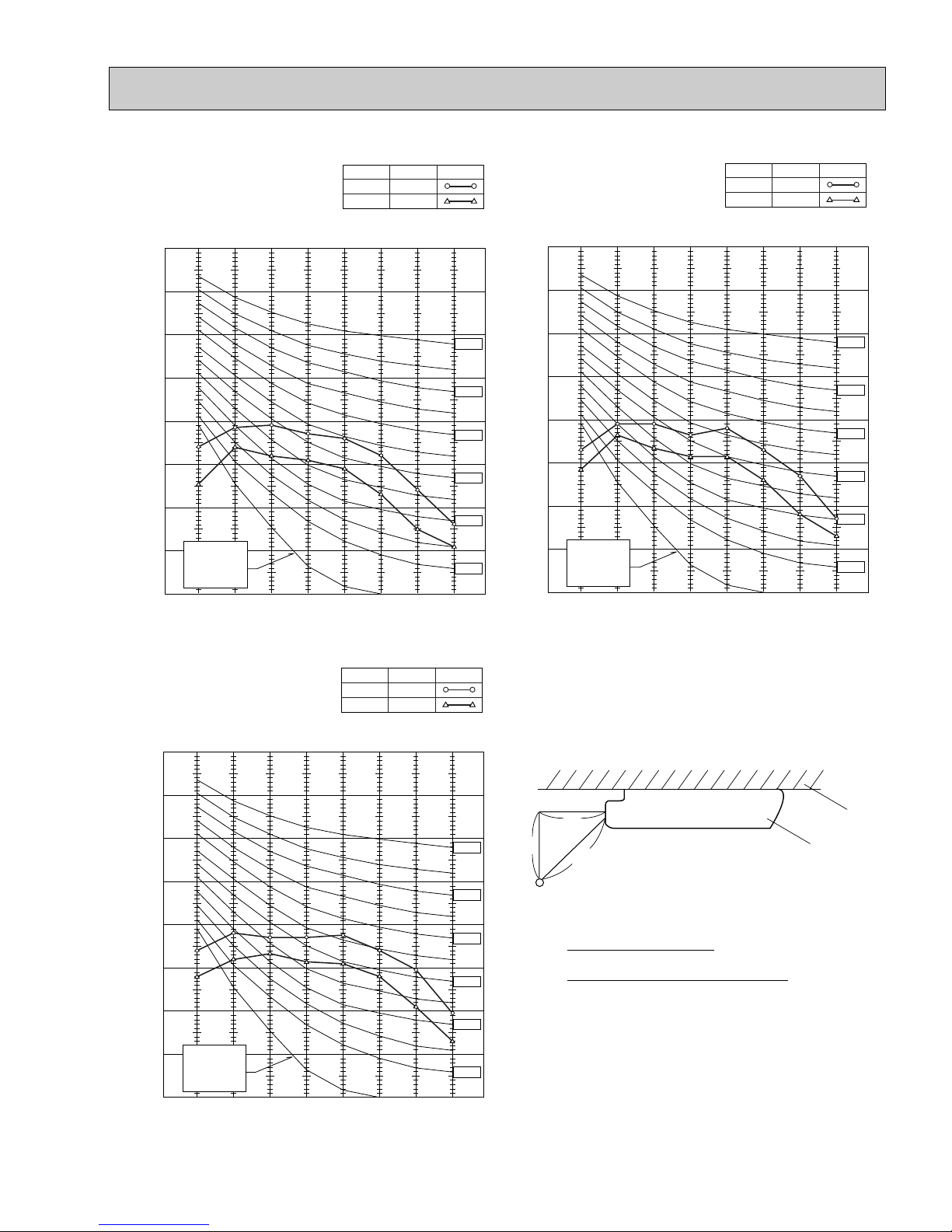
8. NOISE CRITERION CURVES
90
80
70
60
50
40
30
20
10
63 125 250 500 1000 2000 4000 8000
APPROXIMATE
THRESHOLD OF
HEARING FOR
CONTINUOUS
NOISE
NC-60
NC-50
NC-40
NC-30
NC-20
NC-70
OCTAVE BAND SOUND PRESSURE LEVEL, dB re 0.002 MICRO BAR
BAND CENTER FREQUENCIES, Hz
PCH24EK1
PCH30EK1
Hi
Lo
NOTCH
50
43
SPL(dB) LINE
90
80
70
60
50
40
30
20
10
63 125 250 500 1000 2000 4000 8000
APPROXIMATE
THRESHOLD OF
HEARING FOR
CONTINUOUS
NOISE
NC-60
NC-50
NC-40
NC-30
NC-20
NC-70
OCTAVE BAND SOUND PRESSURE LEVEL, dB re 0.002 MICRO BAR
BAND CENTER FREQUENCIES, Hz
PCH36EK1
Hi
Lo
NOTCH
51
45
SPL(dB) LINE
90
80
70
60
50
40
30
20
10
63 125 250 500 1000 2000 4000 8000
APPROXIMATE
THRESHOLD OF
HEARING FOR
CONTINUOUS
NOISE
NC-60
NC-50
NC-40
NC-30
NC-20
NC-70
OCTAVE BAND SOUND PRESSURE LEVEL, dB re 0.002 MICRO BAR
BAND CENTER FREQUENCIES, Hz
PCH42EK1
Hi
Lo
NOTCH
51
45
SPL(dB) LINE
1m
1m
unit
about 1.4m
MICROPHONE
ceiling
Ambient temperature 27˚C
Test conditions are based on JIS Z8731
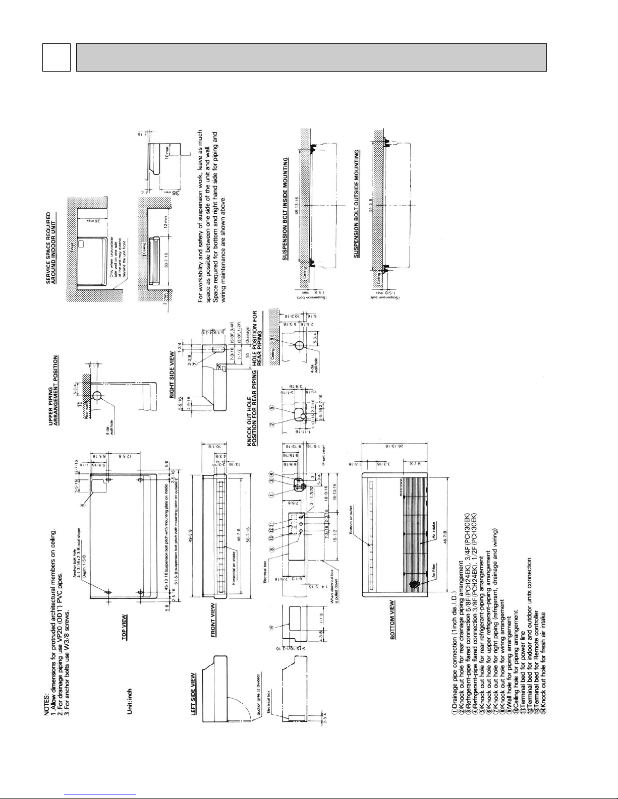
OC193-20
6
OUTLINES AND DIMENSIONS
Indoor unit PCH24/30EK1
Unit:inch
 Loading...