

Page 1
TECHNICAL & SERVICE MANUAL
SPLIT-TYPE,HEAT PUMP AIR CONDITIONERS
CONTENTS
1. SPECIFICATIONS·································3
2. DATA ·····················································4
3.
REFRIGERANT SYSTEM DIAGRAM
········7
4. PARTS LIST··········································8
Indoor unit
PLH-1.6KKB
No. OC169
1998
[
Models
]
PLH-1.6KKB.UK
[
Service Ref.
]
Refer to OC150 for outdoor (PUH-
1.6VKA
3.UK) units, and OC119 for
indoor items other than this manual.
INDOOR UNIT
Ceiling Cassettes
Series PLH
FILTER
CHECK MODE
TEST RUN
CHECK
REMOTE CONTROLLER
The Slim Line.
From Mitsubishi Electric.
Page 2

Page 3
3
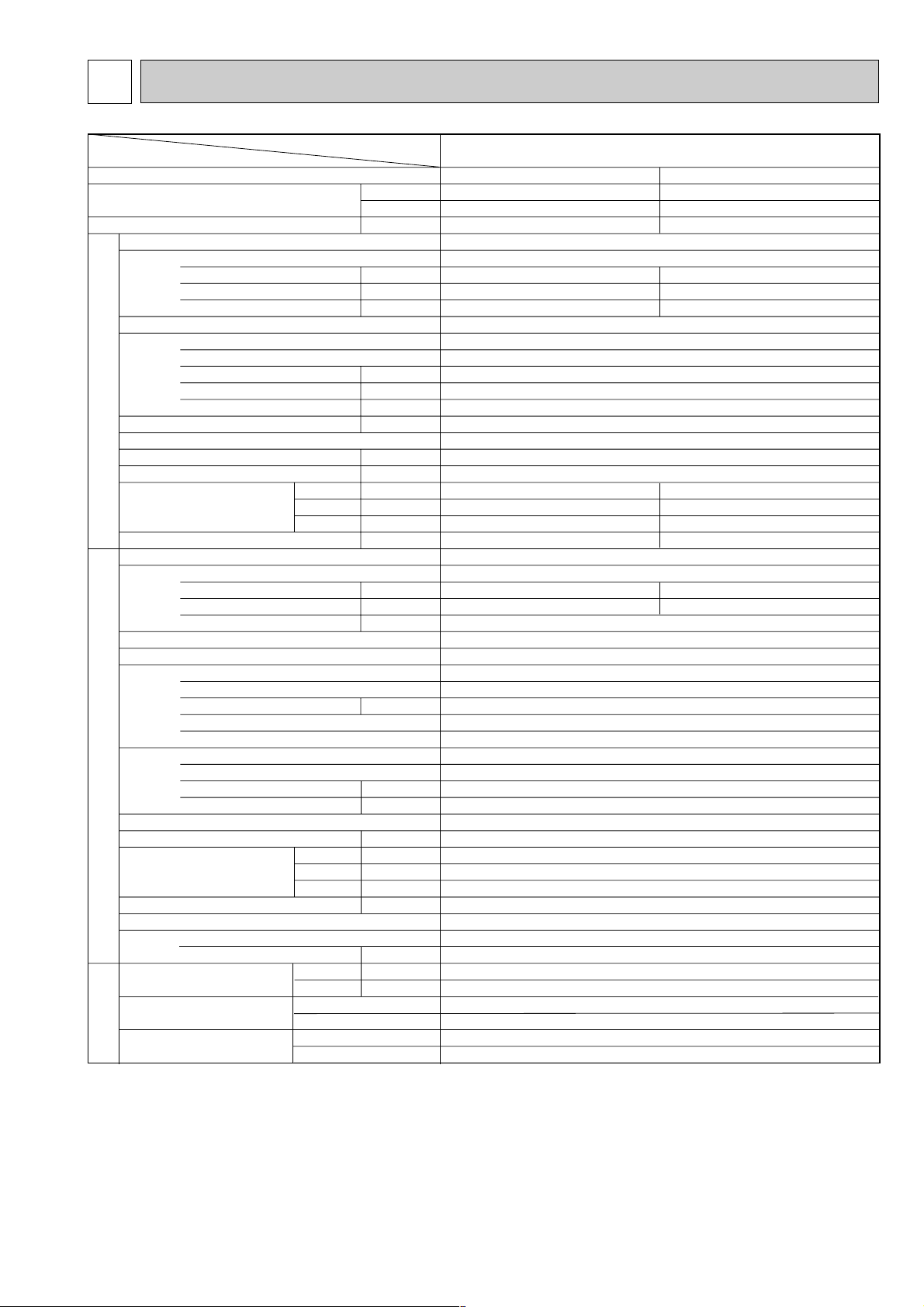
SPECIFICATIONS1
Service Ref.
Power supply(phase, cycle,voltage)
External finish
Heat exchanger
Booster heater
Operation control & Thermostat
Noise level(Low-High)
Cond. drain connection O.D.
Dimensions
Weight
Service Ref.
Power supply (phase, cycle, voltage)
External finish
Refrigerant control
Compressor
Heat exchanger
Defrost method
Noise level
Dimensions
Weight
Refrigerating oil (Model)
Refrigerant
Pipe size O.D.
Connection method
Between the indoor & outdoor unit
Input
Running current
Starting current
Fan(drive) o No.
Fan motor output
Airflow(Low-High)
External static pressure
Input
Running current
Starting current
Model
Motor output
Starter type
Protection devices
Fan(drive) o No.
Fan motor output
Airflow
Charge
W
D
H
W
D
H
Liquid
Gas
Indoor side
Outdoor side
Height difference
Piping length
Function
Capacity
Total input
INDOOR UNITOUTDOOR UNIT
REFRIGERANT
PIPING
Item
Service Ref.
Btu/h
W
kW
kW
A
A
kW
K / min (CFM)
Pa(mmAq)
kW
dB(A)
mm(in)
mm(in)
mm(in)
mm(in)
kg(lbs)
kW
A
A
kW
kW
K / min (CFM)
dB(A)
mm(in)
mm(in)
mm(in)
kg(lbs)
CC
kg(lbs)
mm(in)
mm(in)
PLH-1.6KKB.UK
Cooling
15,000
4,400
1.59
Heating
15,900
4,650
1.51
0.15
0.64
0.70
0.10
0.45
0.50
UNIT : 660(26)
UNIT : 660(26)
UNIT : 253(10)
UNIT : 19(42)
PANEL : 760(30)
PANEL : 760(30)
PANEL : 30(1-1/8)
PANEL : 3.7(8)
1.44
6.74
1.41
6.60
PLH-1.6KKB.UK
Single, 50Hz, 220-240V
33
Galvanized sheets with gray heat insulation
Plate fin coil
Turbo fan (direct) o 1
0.030
13-16(460-565)
0(direct blow)
—
Remote controller & built-in
32-37
32(1-1/4)
PUH-1.6VKA
3.UK
Single, 50Hz, 220-240V
Munsell 5Y 7/1
Capillary tube
Hermetic
RH247VFCT
1.2
Line start
Inner thermostat, High pressure switch
Plate fin coil
Propeller (direct) o1
0.065
45(1,590)
Reverse cycle
49
870(34-1/4)
295+24 (11-5/8 add 1)
650(25-5/8)
53(117)
570(MS-56)
R-22
2.2(4.8)
9.52 (3/8)
15.88(5/8)
Flared
Flared
Max. 40m
Max. 40m
w1. Rating condition (Cooling)…Indoor 27°C D.B., 19.0°C W.B., Outdoor 35°C D.B.
Rating condition (Heating)…Indoor 20°C D.B., Outdoor 7°C D.B., 6°C W.B.
}
(JIS B8616)
Page 4
4
2
DATA
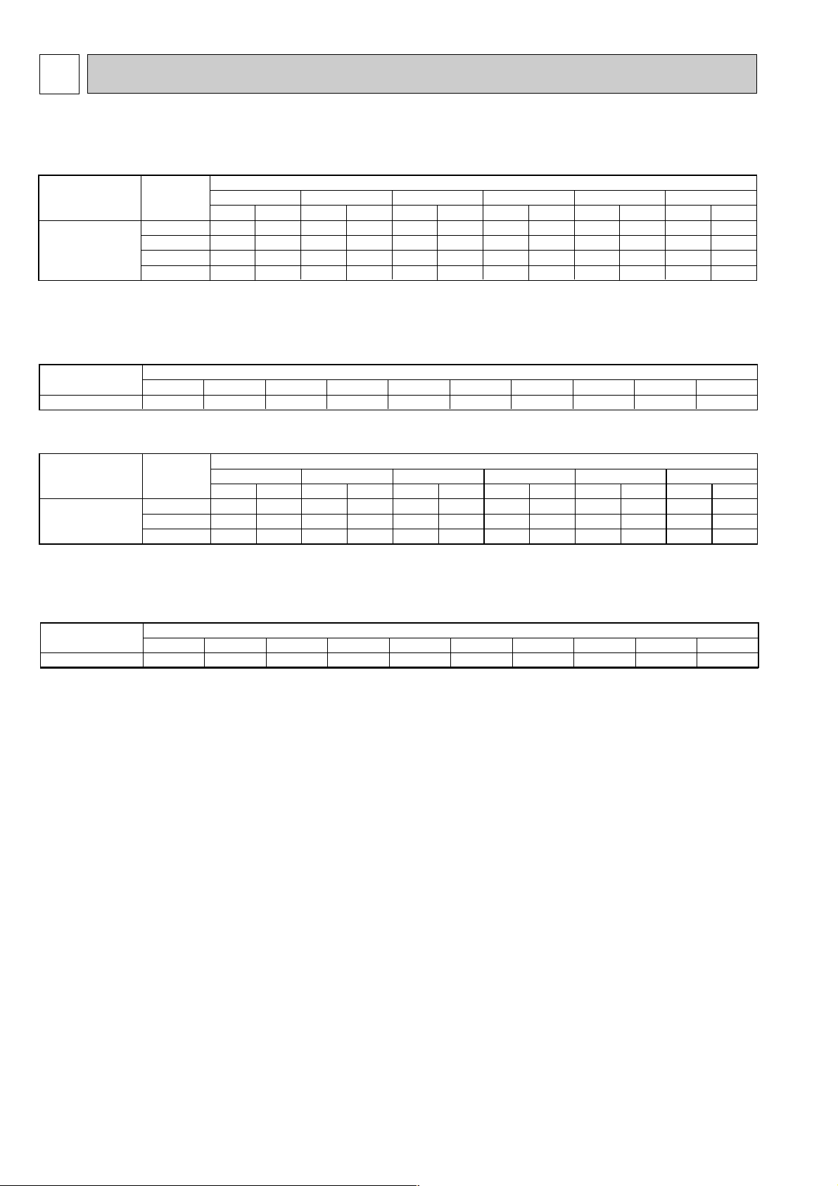
1. PERFORMANCE DATA
1) COOLING CAPACITY
Note CA :Capacity (W)
P.C. :Power consumption (kW)
Cooling capacity correction factors
P.C.
1.74
1.79
1.84
1.90
CA
3,624
3,882
4,154
4,442
P.C.
1.64
1.68
1.72
1.77
CA
3,812
4,074
4,352
4,645
P.C.
1.53
1.57
1.61
1.65
CA
3,990
4,258
4,542
4,840
P.C.
1.43
1.46
1.50
1.53
CA
4,159
4,434
4,724
5,028
P.C.
1.33
1.36
1.38
1.41
CA
4,317
4,602
4,899
5,209
P.C.
1.27
1.30
1.32
1.35
CA
4,439
4,726
5,017
5,310
20 25 30 35 40 45
Outdoor intake air D.B.$C
Indoor
intake air
W.B.$C
16
18
20
22
Service Ref.
PLH-1.6KKB.UK
Refrigerant piping length(one way)
5m
1.00
10m
0.993
15m
0.984
20m
0.978
25m
0.969
30m
0.961
35m
0.956
40m
0.948
45m
–
50m
–
Service Ref.
PLH-1.6KKB.UK
2) HEATING CAPACITY
Note CA :Capacity (W)
P.C. :Power consumption (kW)
Heating capacity correction factors
CA
3,184
3,049
2,930
P.C.
1.03
1.11
1.18
-10
CA
3,650
3,506
3,364
P.C.
1.14
1.23
1.31
-5
CA
4,160
4,003
3,844
P.C.
1.25
1.35
1.44
0
CA
4,714
4,538
4,370
P.C.
1.38
1.48
1.59
5
CA
5,312
5,112
4,942
P.C.
1.51
1.62
1.74
10
CA
5,952
5,724
5,560
P.C.
1.64
1.77
1.90
15
Outdoor intake air D.B.$C
Indoor
intake air
D.B.$C
15
20
25
Service Ref.
PLH-1.6KKB.UK
Refrigerant piping length(one way)
5m
1.00
10m
1.00
15m
1.00
20m
1.00
25m
1.00
30m
1.00
35m
0.998
40m
0.995
45m
–
50m
–
Service Ref.
PLH-1.6KKB.UK
Page 5

5
Heating
1.4
1.2
1.0
0.8
0.6
1.4
1.2
1.0
0.8
0.6
0.4
-12-10 -5 0 5 10 15
OUTDOOR W.B.($C)
INDOOR D.B. ($C)
INDOOR D.B. ($C)
15
20
25
25
20
15
TOTAL INPUT (RATIO) CAPACITY (RATIO)
Cooling
1.4
1.2
1.0
0.8
0.6
1.4
1.2
1.0
0.8
0.6
0.4
-5 5 15 25354552
OUTDOOR D.B.($C)
TOTAL INPUT (RATIO) CAPACITY (RATIO)
INDOOR W.B.($C)
INDOOR W.B.($C)
22
20
18
16
22
20
18
16
2. PERFORMANCE CURVE
PLH-1.6KKB.UK
Input (kW)
Current (A)
Starting current (A)
Input (kW)
Current (A)
Starting current (A)
Mode
Capacity (W)
Total Input (kW)
IndoorOutdoor
Cool
4,300
1.48
0.12
0.60
0.66
1.36
6.79
30
Heat
4,550
1.40
0.08
0.41
0.45
1.32
6.59
30
Indoor unit
Outdoor unit
Indoor unit
Outdoor unit
Service Ref.
Power Supply
PLH-1.6KKB.UK
PUH-1.6VKA
3.UK
220V 50Hz 1phase
220V 50Hz 1phase
Cool
4,350
1.54
0.14
0.62
0.68
1.40
6.76
32
Heat
4,600
1.45
0.09
0.43
0.47
1.36
6.57
32
PLH-1.6KKB.UK
PUH-1.6VKA
3.UK
230V 50Hz 1phase
230V 50Hz 1phase
Cool
4,400
1.59
0.15
0.64
0.70
1.44
6.74
33
Heat
4,650
1.51
0.10
0.45
0.50
1.41
6.60
33
PLH-1.6KKB.UK
PUH-1.6VKA
3.UK
240V 50Hz 1phase
240V 50Hz 1phase
3. ELECTRICAL DATA
Page 6

6
Capacity
Input
Indoor unit Service Ref.
Phase,Hz
Volts
Amperes
Outdoor unit Service Ref.
Phase,Hz
Volts
Amperes
Discharge pressure
Suction pressure
Discharge temperature
Condensing temperature
Suction temperature
Ref. pipe length
Intake air temperature
Discharge air temperature
Intake air temperature
SHF
BF
Mode
Total
W
kW
V
A
V
A
MPa•G
(kgf/F•G)
MPa•G
(kgf/F•G)
$C
$C
$C
m
D.B.$C
W.B.$C
D.B.$C
D.B.$C
W.B.$C
PLH-1.6KKB.UKService Ref.
Cooling
4,400
1.59
Heating
4,650
1.51
6.74
1.80
(18.3)
0.54
(5.51)
78.7
48.5
8.5
5
27
19
16.1
35
24
0.83
0.21
6.60
1.70
(17.3)
0.40
(4.08)
77.2
–
0.7
5
20
15
35.2
7
6
–
–
0.64 0.45
PLH-1.6KKB.UK
1,50
240
PUH-1.6VKA
3.UK
1,50
240
Electrical circuitRefrigerant circuit
Indoor
side
Outdoor
side
Air flow
Air speed
Coverage range
K/min
m/W.
m
PLH-1.6KKB.UK
16.0
5.6
6.0
Air flow
Air speed
Coverage range
Total width of discharge outlets
K/min
m/W.
m
mm
17.0
5.9
6.4
0
Standard
High ceiling
4. STANDARD OPERATION DATA
5. OUTLET AIR SPEED AND COVERAGE RANGE
W The air coverage range is the value up to the position where the air speed is 0.25m/sec.
When air is blown out horizontally from the unit at the Hi notch position.
The coverage range should be used only as a general guideline since it varies according to the size of the room and
the furniture inside the room.
The unit of pressure has been changed to Mpa based on the international SI system.
The corversion factor is : 1 (Mpa·G) = 10.2 (kgf/cm2·G)
Page 7

7
REFRIGERANT SYSTEM DIAGRAM3
W1
O.D.{3.2oI.D.{1.6–R630
O.D.{3.2oI.D.{1.8–R600
High pressure protect switch
PLH-1.6KKB.UK / PUH-1.6VKA3.UK
Unit : mm
Page 8

8
PARTS LIST4
PANEL PARTS
PLH-1.6KKB.UK
1
2
3
4
5
6
7
T7W 560 003
R01 29H 500
R01 29H 691
R01 29H 061
T7W 14K 200
T7W 556 305
Part No. Part Name SpecificationNo.
Wining
Diagram
Symbol
Recommended
Q,ty
Price
Unit
Amount
AIR OUTLET GRILLE
AIR FILTER
INTAKE GRILLE
HINGE
–
GRILLE HANGER
REMOTE CONTROLLER
REMOTE CONTROLLER CABLE
12m
R.B
Remarks
(Drawing No.)
1
1
1
2
1
1
1
Q,ty/set
PLH-1.6
KKB.UK
(BG88H096H01)
7
2
3
1
4
5
6
Page 9

9
PANEL PARTS
PLH-1.6KKB.UK
1
2
3
4
5
6
7
R01 29H 002
R01 29H 085
R01 29H 223
R01 29H 063
R01 29H 056
R01 29H 047
Part No. Part Name SpecificationNo.
Wining
Diagram
Symbol
Recommended
Q,ty
Price
Unit
Amount
AUTO VANE
AIR GUIDE
VANE MOTOR
SPRING JOINT 1
T7W 33K 063
SPRING JOINT
PUSH BUTTON
VANE SUPPORT
8
T7W 560 258
COARD HEATER
9
R01 29H 040
GRILLE GEAR (RIGHT)
10
R01 29H 041
GRILLE GEAR (LEFT)
240V 28.2W
H
MV
Remarks
4
1
1
1
1
1
8
1
1
1
<3/SET>
Q,ty/set
PLH-1.6
KKB.UK
114
4
4
7
10
7
1
3
79
7
7
6
2
1
5
8
Page 10

10
FUNCTIONAL PARTS
PLH-1.6KKB.UK
1
3
6
7
2
5
2
13
14
24
25
26
23
16
9
20
22
18
3
4
30 2927
8
10
34
11
17
31
19
21
28
15
34
Page 11

11
Part No. Part Name SpecificationNo.
Part numbers that are circled not shown in the figure.
1
2
3
4
T7W E00 762
5
R01 29H 105
6
7
R01 41N 114
8
R01 08K 202
9
R01 29H 523
10
T7W 55K 355
11
R01 W28 266
12
R01 W28 527
T7W 580 480
13
S70 A00 529
14
15
16
17
18
19
20
T7W 521 716
21
T7W 517 716
22
T7W 515 716
23
R01 29H 255
24
25
T7W 58K 310
26
T7W 520 239
27
T7W 580 799
R01 J07 202
28
29
30
R01 08K 097
31
R01 A48 524
32
33
R01 005 533
34
S70 A00 675
Unit
Price
Amount
Q,ty/set
PLH-1.6
KKB.UK
–
–
–
–
–
–
–
–
–
–
–
–
BASE
LEG
LEG
FAN MOTOR
MOTOR MOUNT
INNER COVER
TURBO FAN
INDOOR COIL THERMISTOR
DRAIN SOCKET
DRAIN PUMP
DRAIN SENSOR
DRAIN HOSE
HEAT EXCHANGER
DRAIN PAN
CORNER SUPPORT(1)
CORNER SUPPORT(2)
CORNER SUPPORT(2)
CORNER SUPPORT(3)
LEAD WIRE COVER
TERMINAL BLOCK
TERMINAL BLOCK
TERMINAL BLOCK
FAN MOTOR CAPACITOR
CONTROLLER CASE
INDOOR CONTROLLER BOARD
FUSE
TRANSFORMER
ROOM TEMPERATURE THERMISTOR
BELL MOUTH
ELECTRICAL PARTS COVER
SPL WASHER
DRAIN PLUG
SENSOR HOLDER
FAN GUARD
PAI-V30F
3P(L,N,
3P(1,2,3)
2P(1,2)
2.5+F 400V
250V 6.3A
;
)
1
2
2
1
3
1
1
1
1
1
1
1
1
1
1
1
1
1
1
1
1
1
1
1
1
1
1
1
1
1
1
1
1
1
Remarks
(Drawing No.)
(BG00T765G01)
(BG00K209G01)
(BG00K209G02)
(BG00T770G01 )
(BG00K210G01)
(BG00K211G01)
(BG00K212G01)
(RG00T856G01)
(BG00T861G01)
(BG25J542H04)
F1<I.B>
(BG00N936G07)
(RG00C610G01)
Wining
Diagram
Symbol
MF1
RT2
DP
DS
TB2
TB4
TB5
C1
I.B
T
RT1
Recommended
Q,ty
Page 12

HEAD OFFICE MITSUBISHI DENKI BLDG.MARUNOUCHI TOKYO100 TELEX J24532 CABLE MELCO TOKYO
CCopyright 1997 MITSUBISHI ELECTRIC ENGINEERING CO., LTD.
Issued in Aug.1998. No. OC169 301
Printed in Japan.
New publication, effective Aug 1998.
Specifications subject to change without notice.
 Loading...