

Mitsubishi PEA-RP·GA, PLA-RP·BA2, PKA-RP·HAL, PKA-RP·KAL, PCA-RP·KA Technical Data Book
...
TECHNICAL DATA BOOK
CONTENTS
1. REFERENCE SERVICE MANUAL
.............................................
2
2. SPECIFICATIONS
.......................................................................
3
3. OUTLINES AND DIMENSIONS
................................................
15
4. WIRING DIAGRAM
...................................................................
36
5. REFRIGERANT SYSTEM DIAGRAM
......................................
48
6. PERFORMANCE CURVES
......................................................
52
7. CORRECTION FACTORS
........................................................
54
8. APPLICABLE EXTENSION PIPE FOR EACH MODEL
..........
55
9. AIR FLOW DATA
......................................................................
59
10. NOISE CRITERION CURVES
...................................................
73
11. OPTIONAL PARTS
....................................................................
87
<Indoor unit>
[Model names]
R410A
<Outdoor unit>
[Model names]
No. OCS17
SPLIT-TYPE, HEAT PUMP AIR CONDITIONERS
PUHZ-P100/125/140VHA3
PUHZ-P100/125/140YHA
PUHZ-P200/250YHA3
December 2009
INVERTER
kW Model
PLA-RP·BA/BA2/BA3
PEAD-RP·JA(L)
PEA-RP·GA
PKA-RP·HAL
PKA-RP·KAL
PCA-RP·KA
PCA-RP·HA
PSA-RP·GA
2
1
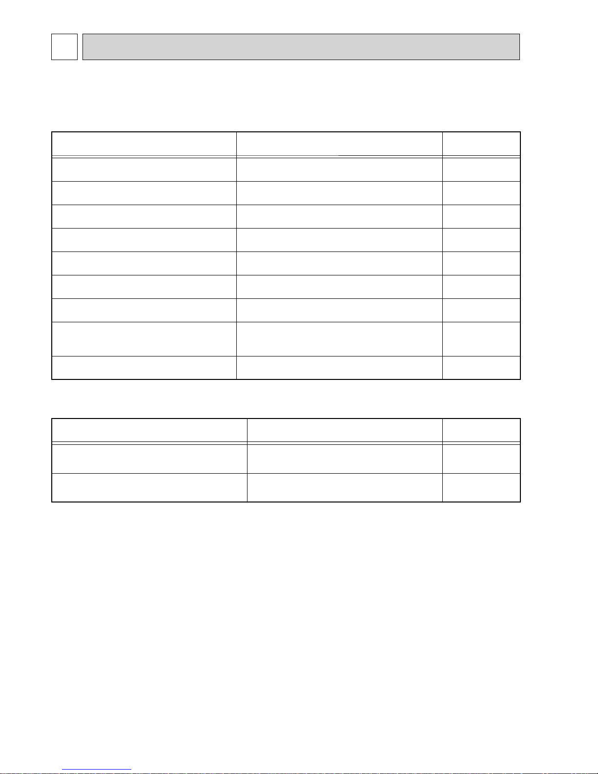
REFERENCE SERVICE MANUAL
For information on service, please refer to the service manual as follows.
1-1. INDOOR UNIT SERVICE MANUAL
Model name Service Ref.
Service
Manual No.
PLA-RP50/60/71/100/125BA
PLA-RP71/125/140BA2
PLA-RP50/60/71/100/125BA#2.UK
PLA-RP71/125/140BA2.UK
OCH412
OCB412
PLA-RP100BA3 PLA-RP100BA3
OCH459
OCB459
PCA-RP50/60/71/100/125/140KA PCA-RP50/60/71/100/125/140KA
OCH454
OCB454
PCA-RP71/125HA PCA-RP71/125HA#1 OC329
PKA-RP50HAL PKA-RP50HAL
OCH453
OCB453
PKA-RP60/71/100KAL PKA-RP60/71/100KAL.TH
OCH452
OCB452
PSA-RP71/100/125/140GA PSA-RP71/100/125/140GA#1 OC332
PEAD-RP50/60/71/100/125/140JA(L) PEAD-RP50/60/71/100/125/140JA(L)(R1).UK
HWE08130
BWE08240
BWE09220
PEA-RP200/250/400/500GA
PEA-RP200/250/400/500GA.TH-AF
PEA-RP200/250GA.TH-AFMF
HWE0708A
1-2. OUTDOOR UNIT
Model name Service Ref.
Service
Manual No.
PUHZ-P100/125/140VHA3
PUHZ-P100/125/140YHA
PUHZ-P100/125/140VHA3R2.UK
PUHZ-P100/125/140YHA.UK
OCH415
OCB415
PUHZ-P200/250YHA3 PUHZ-P200/250YHA3R1
OCH424
OCB424
3
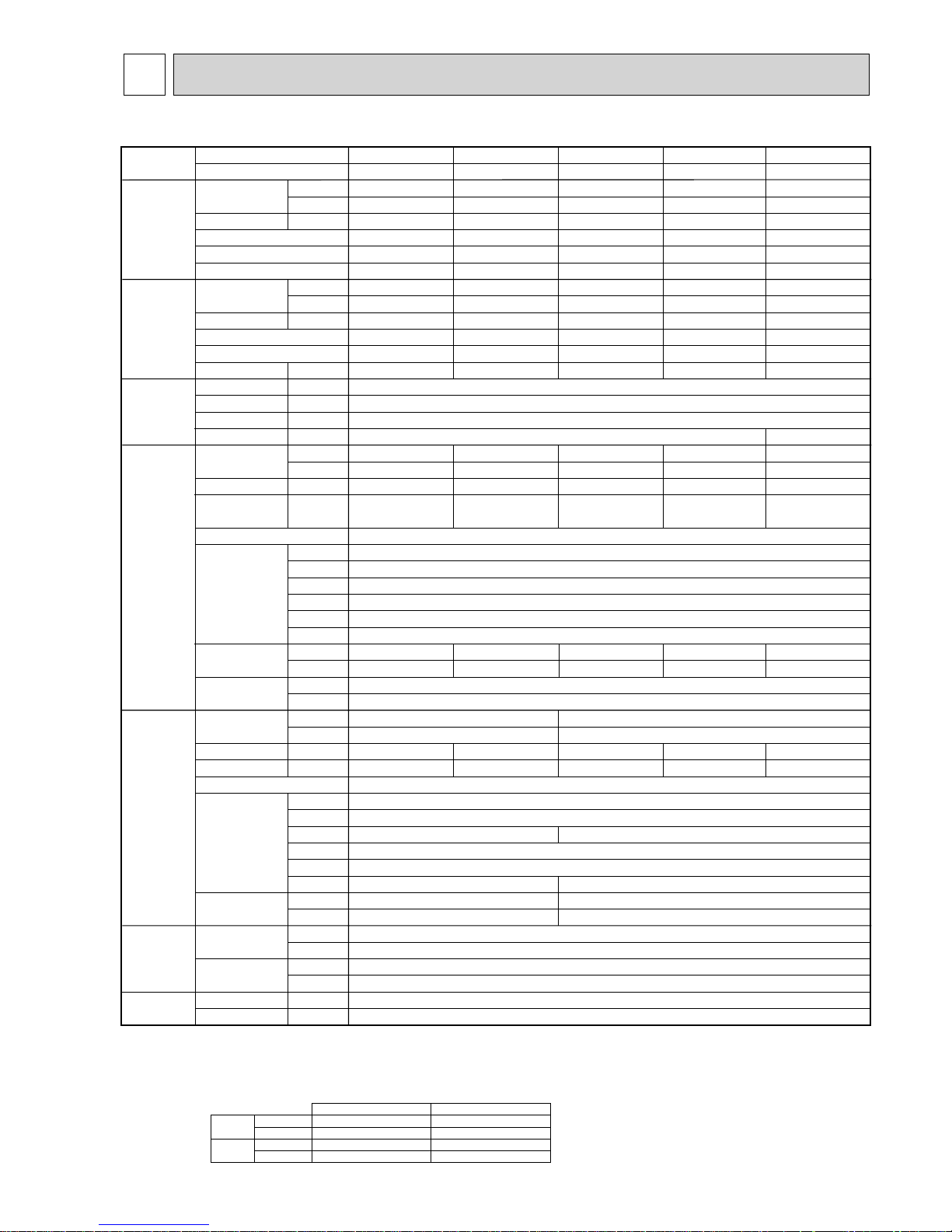
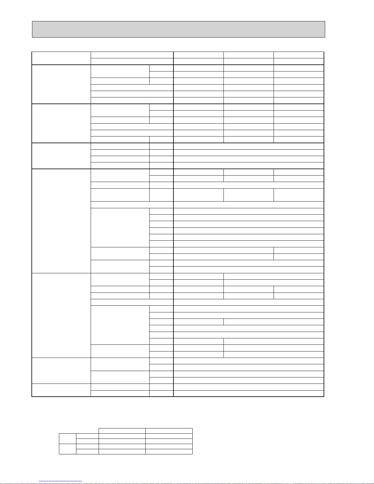
2
SPECIFICATIONS
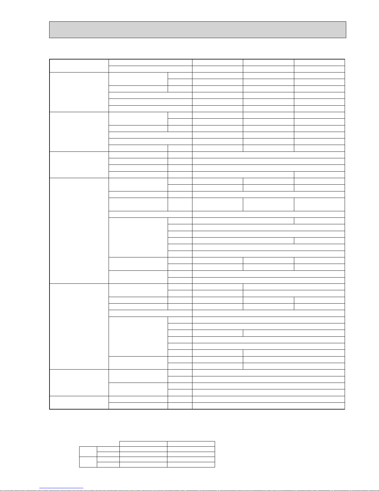
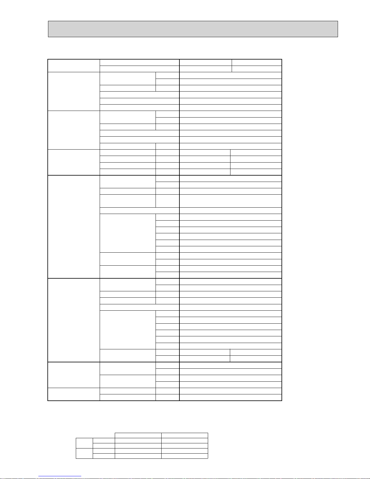
2-1. CEILING CASSETTE TYPE
NOTE: 1. Rating conditions (ISO T1)
Cooling Indoor : D.B. 27 (80°F) W.B. 19 (66°F) Outdoor : D.B. 35 (95°F) W.B. 24 (75°F)
Heating Indoor : D.B. 20 (68°F) Outdoor : D.B. 7 (45°F) W.B. 6 (43°F)
Refrigerant piping length (one way) : 5m (16ft.)
2. Guaranteed operating range
Indoor Outdoor
Cooling
Upper limit
D.B. 35°C, W.B. 22.5°C
D.B. 46
Lower limit
D.B. 19°C, W.B. 15°C D.B. -5 +
Heating
Upper limit
D.B. 28°C
D.B. 21, W.B. 15
Lower limit
D.B. 17°C
D.B. -15, W.B. -15
4. Above data are based on the indicated voltage.
+ If optional air protect guide is installed : D.B.-15
Indoor unit Single phase 230V 50Hz
Single phase 230V 50Hz
Outdoor unit
3. Guaranteed voltage
198~264V, 50Hz
Model name Indoor unit PLA-RP100BA PLA-RP125BA PLA-RP125BA2
Outdoor unit PUHZ-P100VHA3 PUHZ-P125VHA3 PUHZ-P125VHA3
Cooling Capacity Btu/h 32,100 42,000 42,000
kW 9.4(4.9-11.2
)
12.3(5.5-14.0)12.3(5.5-14.0
)
Total input kW 3.12 4.09 4.09
EER 3.01 3.01 3.01
Energy label class
BB-
SHF 0.74 0.71 0.71
Heating Capacity Btu/h 38,200 47,800 47,800
kW 11.2 (4.5-12.5
)
14.0(5.0-16.0)14.0(5.0-16.0
)
Total input kW 3.28 4.11 4.02
COP 3.41 3.41 3.48
Energy label class
BB-
Booster heater kW - - -
Power supply
Phase W 1
Cycle Hz 50
Voltage V 230
Breaker size A 32
Indoor unit Air flow CMM 20-23-26-30 22-25-28-31
(
Low-Medium2-Medium1-High
)
CFM
710-810-920-1060 780-880-990-1090
External pressure
Pa 0 0
Sound level dB(A
)
32-34-37-40 34-36-39-41
22-25-28-31
780-880-990-1090
0
34-36-39-41
(
Low-Medium2-Medium1-High
)
External finish (Panel
)
White Munsell 6.4Y 8.9/0.4
Dimension W : mm 840(950
)
Unit(Panel
)
D : mm 840(950
)
H : mm 298(35
)
W : inch 33-1/16(37-3/8
)
D : inch 33-1/16(37-3/8
)
H : inch 11-3/4 (1-3/8
)
Weight kg
25 (6)
Unit(Panel
)
lbs
55 (13)
27 (6)
60 (13)
Field drain pipe O.D.
mm 32
inch 1-1/4
Outdoor unit Air flow CMM 60 100
CFM 2,120 3,530
Sound level at cooling
dB(A
)
50 51 51
Sound level at heating
dB(A
)
54 55 55
External finish Ivory Munsell 3Y 7.8/1.1
Dimension W : mm 950
D : mm 330+30
H : mm 1350
W : inch 37-3/8
D : inch 13 + 1-3/16
H : inch 53-1/8
Weight kg 99
lbs 218
Refrigerant
pipe size
Gas side O.D. mm 15.88
inch 5/8
Liquid side O.D. mm 9.52
inch 3/8
Refrigerant
pipe length
Height difference
m Max. 30
Length
m Max. 50
PLA-RP100BA3
PUHZ-P100VHA3
32,100
9.4(4.9-11.2
)
3.12
3.01
-
0.74
38,200
11. 2 (4.5-12.5
)
3.22
3.48
-
-
20-23-26-30
710-810-920-1060
0
32-34-37-40
50
54
943
37-1/8
75
165
PLA-RP140BA2
PUHZ-P140VHA3
46,400
13.6(5.5-15.0
)
5.21
2.61
D
0.71
54,600
16.0(5.0-18.0
)
4.98
3.21
C
-
40
24-26-29-32
850-920-1020-1130
0
36-39-42-44
27 (6)
60 (13)
52
56
26 (6) 25 (6)
55 (13)
57 (13)
4
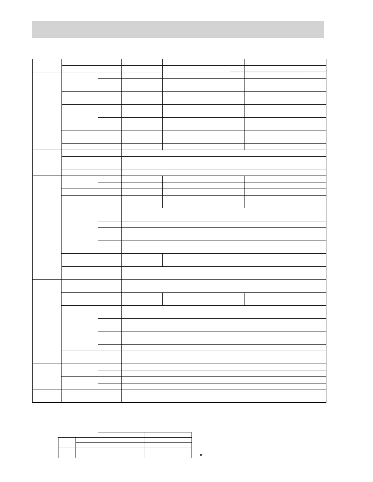
Model name Indoor unit PLA-RP100BA PLA-RP125BA PLA-RP125BA2
Outdoor unit PUHZ-P100YHA PUHZ-P125YHA PUHZ-P125YHA
Cooling Capacity Btu/h 32,100 42,000 42,000
kW 9.4(4.9-11.2
)
12.3(5.5-14.0)12.3(5.5-14.0
)
Total input kW 3.12 4.09 4.09
EER 3.01 3.01 3.01
Energy label class
BB-
SHF 0.74 0.71 0.71
Heating Capacity Btu/h 38,200 47,800 47,800
kW 11.2 (4.5-12.5
)
14.0(5.0-16.0)14.0(5.0-16.0
)
Total input kW 3.28 4.11 4.02
COP 3.41 3.41 3.48
Energy label class
BB-
Booster heater kW - - -
Power supply
Phase W 3
Cycle Hz 50
Voltage V 400
Breaker size A 16
Indoor unit Air flow CMM 20-23-26-30 22-25-28-31
(
Low-Medium2-Medium1-High
)
CFM
710-810-920-1060 780-880-990-1090
External pressure
Pa 0 0
Sound level dB(A
)
32-34-37-40 34-36-39-41
22-25-28-31
780-880-990-1090
0
34-36-39-41
(
Low-Medium2-Medium1-High
)
External finish (Panel
)
White Munsell 6.4Y 8.9/0.4
Dimension W : mm 840(950
)
Unit(Panel
)
D : mm 840(950
)
H : mm 298(35
)
W : inch 33-1/16(37-3/8
)
D : inch 33-1/16(37-3/8
)
H : inch 11-3/4 (1-3/8
)
Weight kg
25 (6)
Unit(Panel
)
lbs 55 (13)
27 (6)
60 (13)
Field drain pipe O.D.
mm 32
inch 1-1/4
Outdoor unit Air flow CMM 60 100
CFM 2,120 3,530
Sound level at cooling
dB(A
)
50 51 51
Sound level at heating
dB(A
)
54 55 55
External finish Ivory Munsell 3Y 7.8/1.1
Dimension W : mm 950
D : mm 330+30
H : mm 1350
W : inch 37-3/8
D : inch 13 + 1-3/16
H : inch 53-1/8
Weight kg 101
lbs 222
Refrigerant
pipe size
Gas side O.D. mm 15.88
inch 5/8
Liquid side O.D. mm 9.52
inch 3/8
Refrigerant
pipe length
Height difference
mMax. 30
Length
mMax. 50
PLA-RP100BA3
PUHZ-P100YHA
32,100
9.4(4.9-11.2
)
3.12
3.01
-
0.74
38,200
11. 2 (4.5-12.5
)
3.22
3.48
-
-
20-23-26-30
710-810-920-1060
0
32-34-37-40
50
54
943
37-1/8
77
169
PLA-RP140BA2
PUHZ-P140YHA
46,400
13.6(5.5-15.0
)
5.21
2.61
D
0.71
54,600
16.0(5.0-18.0
)
4.98
3.21
C
-
24-26-29-32
850-920-1020-1130
0
36-39-42-44
27 (6)
60 (13)
52
56
26 (6) 25 (6)
55 (13)
57 (13)
NOTE: 1. Rating conditions (ISO T1)
Cooling Indoor : D.B. 27 (80°F) W.B. 19 (66°F) Outdoor : D.B. 35 (95°F) W.B. 24 (75°F)
Heating Indoor : D.B. 20 (68°F) Outdoor : D.B. 7 (45°F) W.B. 6 (43°F)
Refrigerant piping length (one way) : 5m (16ft.)
2. Guaranteed operating range
Indoor Outdoor
Cooling
Upper limit
D.B. 35°C, W.B. 22.5°C
D.B. 46°C
Lower limit
D.B. 19°C, W.B. 15°C D.B. -5°C +
Heating
Upper limit
D.B. 28°C
D.B. 21°C, W.B. 15°C
Lower limit
D.B. 17°C
D.B. -15°C, W.B. -15°C
4. Above data are based on the indicated voltage.
Indoor unit Single phase 230V 50Hz
3 phase 400V 50Hz
Outdoor unit
Indoor unit 198~264V, 50Hz
342~457V, 50Hz
Outdoor unit
3. Guaranteed voltage
If optional air protect guide installed. D.B.-15
5
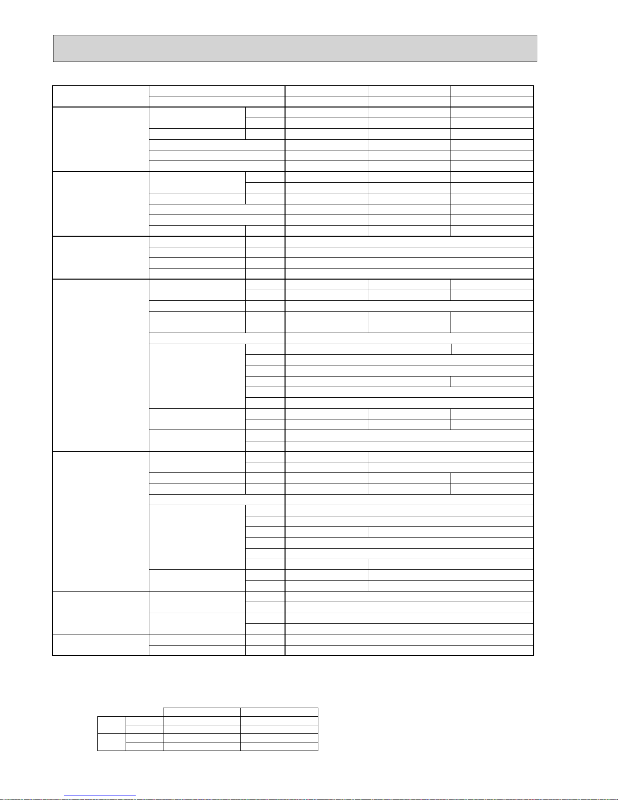
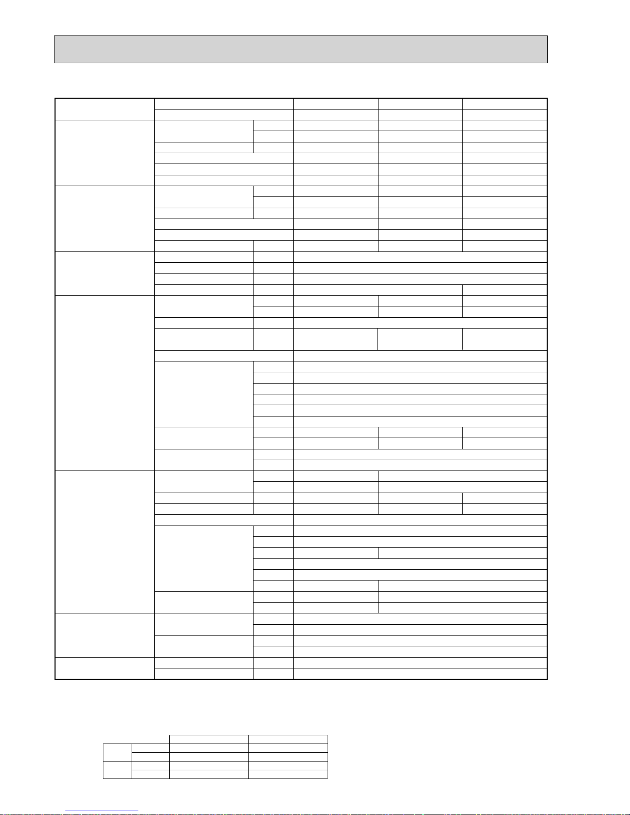
NOTE: 1. Rating conditions (ISO T1)
Cooling Indoor : D.B. 27 (80°F) W.B. 19 (66°F) Outdoor : D.B. 35 (95°F) W.B. 24 (75°F)
Heating Indoor : D.B. 20 (68°F) Outdoor : D.B. 7 (45°F) W.B. 6 (43°F)
Refrigerant piping length (one way) : 5m (16ft.)
2. Guaranteed operating range
Indoor Outdoor
Cooling
Upper limit
D.B. 35°C, W.B. 22.5°C
D.B. 46
Lower limit
D.B. 19°C, W.B. 15°C D.B. -5 +
Heating
Upper limit
D.B. 28°C
D.B. 21, W.B. 15
Lower limit
D.B. 17°C
D.B. -15, W.B. -15
4. Above data are based on the indicated voltage.
+ If optional air protect guide is installed : D.B.-15
Indoor unit Single phase 230V 50Hz
Single phase 230V 50Hz
Outdoor unit
3. Guaranteed voltage
198~264V, 50Hz
Model name Indoor unit PEAD-RP100JA(L) PEAD-RP125JA(L) PEAD-RP140JA(L)
Outdoor unit PUHZ-P100VHA3 PUHZ-P125VHA3 PUHZ-P140VHA3
Cooling Capacity Btu/h 32,100 42,000 46,400
kW 9.4 (4.9-11.2) 12.3 (5.5-14.0) 13.6 (5.5-15.0)
Total input kW 3.04 (3.02) 4.22 (4.20) 4.52 (4.50)
EER 3.09 (3.11) 2.91 (2.93) 3.01 (3.02)
Energy label class B C B
SHF 0.85 0.85 0.84
Heating Capacity Btu/h 38,200 47,800 54,600
kW 11.2 (4.5-12.5) 14.0 (5.0-16.0) 16.0 (5.0-18.0)
Total input kW 3.10 3.87 4.43
COP 3.61 3.62 3.61
Energy label class A A A
Booster heater kW - - -
Power supply Phase W 1
Cycle Hz 50
Voltage V 230
Breaker size A 32 40
Indoor unit Air flow CMM 24 - 29 - 34 29.5 - 35.5 - 42 32 - 39 - 46
(
Low-Mid-High
)
CFM 847-1024-1201 1042-1253-1483 1130-1377-1624
External pressure Pa 35 / 50 / 70 / 100 / 150
Sound level dB(A
)
29 - 34 - 38 33 - 36 - 40 34 - 38 - 43
(
Low-Mid-High
)
External finish Galvanized sheets
Dimension W : mm
250
D : mm
1400
H : mm
732
W : inch 55-1/8 63
D : inch 28-7/8
H : inch 9-7/8
Weight kg 41 (40) 43 (42) 47 (46)
lbs
mm
inch
91 (89) 95 (93) 104 (102)
Field drain pipe O.D. 32
1-1/4
Outdoor unit Air flow CMM 60 100
CFM 2,120 3,530
Sound level at cooling dB(A
)
50 51 52
Sound level at heating dB(A
)
54 55 56
External finish Ivory Munsell 3Y 7.8/1.1
Dimension W : mm 950
D : mm 330(+30)
H : mm 943 1350
W : inch 37-3/8
D : inch 13 + 1-3/16
H : inch 37-1/8 53-1/8
Weight kg 75 99
lbs 165 218
Refrigerant pipe size Gas side O.D. mm 15.88
inch 5/8
Liquid side O.D. mm 9.52
inch 3/8
Refrigerant pipe length Height difference m Max. 30
Length m Max. 50
1600
2-2. CEILING-CONCEALED TYPE
6
Model name Indoor unit PEAD-RP100JA(L) PEAD-RP125JA(L) PEAD-RP140JA(L)
Outdoor unit PUHZ-P100YHA PUHZ-P125YHA PUHZ-P140YHA
Cooling Capacity Btu/h 32,100 42,000 46,400
kW 9.4 (4.9-11.2) 12.3 (5.5-14.0) 13.6 (5.5-15.0)
Total input kW 3.04 (3.02) 4.22 (4.20) 4.52 (4.50)
EER 3.09 (3.11) 2.91 (2.93) 3.01 (3.02)
Energy label class B C B
SHF 0.85 0.85 0.84
Heating Capacity Btu/h 38,200 47,800 54,600
kW 11.2 (4.5-12.5) 14.0 (5.0-16.0) 16.0 (5.0-18.0)
Total input kW 3.10 3.87 4.43
COP 3.61 3.62 3.61
Energy label class A A A
Booster heater kW - - -
Power supply Phase W 3
Cycle Hz 50
Voltage V 400
Breaker size A 16
Indoor unit Air flow CMM
(
Low-Mid-High
)
CFM
External pressure Pa 35 / 50 / 70 / 100 / 150
Sound level dB(A
)
29 - 34 - 38 33 - 36 - 40 34 - 38 - 43
(
Low-Mid-High
)
External finish Galvanized sheets
Dimension W : mm
250
D : mm
1400
H : mm
732
W : inch
D : inch
H : inch
Weight kg
lbs
mm
inch
Field drain pipe O.D. 32
1-1/4
Outdoor unit Air flow CMM 60 100
CFM 2,120 3,530
Sound level at cooling dB(A
)
50 51 52
Sound level at heating dB(A
)
54 55 56
External finish Ivory Munsell 3Y 7.8/1.1
Dimension W : mm 950
D : mm 330(+30)
H : mm 943 1350
W : inch 37-3/8
D : inch 13 + 1-3/16
H : inch 37-1/8 53-1/8
Weight kg 77 101
lbs 169 222
Refrigerant pipe size Gas side O.D. mm 15.88
inch 5/8
Liquid side O.D. mm 9.52
inch 3/8
Refrigerant pipe length Height difference m Max. 30
Length m Max. 50
1600
24 - 29 - 34 29.5 - 35.5 - 42 32 - 39 - 46
847-1024-1201 1042-1253-1483 1130-1377-1624
55-1/8 63
28-7/8
9-7/8
41 (40) 43 (42) 47 (46)
91 (89) 95 (93) 104 (102)
NOTE: 1. Rating conditions (ISO T1)
Cooling Indoor : D.B. 27 (80°F) W.B. 19 (66°F) Outdoor : D.B. 35 (95°F) W.B. 24 (75°F)
Heating Indoor : D.B. 20 (68°F) Outdoor : D.B. 7 (45°F) W.B. 6 (43°F)
Refrigerant piping length (one way) : 5m (16ft.)
2. Guaranteed operating range
Indoor Outdoor
Cooling
Upper limit
D.B. 35°C, W.B. 22.5°C
D.B. 46°C
Lower limit
D.B. 19°C, W.B. 15°C D.B. -5°C +
Heating
Upper limit
D.B. 28°C
D.B. 21°C, W.B. 15°C
Lower limit
D.B. 17°C
D.B. -15°C, W.B. -15°C
4. Above data are based on the indicated voltage.
Indoor unit Single phase 230V 50Hz
3 phase 400V 50Hz
Outdoor unit
Indoor unit 198~264V, 50Hz
342~457V, 50Hz
Outdoor unit
3. Guaranteed voltage
+ If optional air protect guide installed. D.B.-15
7
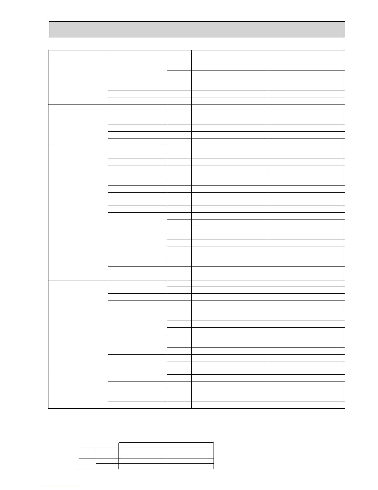
NOTE: 1. Rating conditions (ISO T1)
Cooling Indoor : D.B. 27 (80°F) W.B. 19 (66°F) Outdoor : D.B. 35 (95°F) W.B. 24 (75°F)
Heating Indoor : D.B. 20 (68°F) Outdoor : D.B. 7 (45°F) W.B. 6 (43°F)
Refrigerant piping length (one way) : 5m (16ft.)
2. Guaranteed operating range
Indoor Outdoor
Cooling
Upper limit
D.B. 35°C, W.B. 22.5°C
D.B. 46°C
Lower limit
D.B. 19°C, W.B. 15°C D.B. -5°C +1
Heating
Upper limit
D.B. 28°C
D.B. 21°C, W.B. 15°C
Lower limit
D.B. 17°C
D.B. -11°C, W.B. -12°C
4. Above data are based on the indicated voltage.
+1. If optional air protect guide is installed : D.B.-15
Indoor unit 3 phase 400V 50Hz
3 phase 400V 50Hz
Outdoor unit
3. Guaranteed voltage
342~457V, 50Hz
Model name Indoor unit PEA-RP200GA PEA-RP250GA
Outdoor unit PUHZ-P200YHA3 PUHZ-P250YHA3
Cooling Capacity Btu/h 65,000 75,000
kW 19.0(9.0-22.4) 22.0(11.2-28.0)
Total input kW 7.21 8.44
EER
Energy label class
2.64 2.61
DD
SHF 0.81 0.86
Heating Capacity Btu/h 76,000 92,000
kW 22.4(9.5-25.0) 27.0(12.5-31.5)
Total input kW 7.36 8.47
COP 3.04 3.19
Energy label class D D
Booster heater kW - -
Power supply Phase : 3
Cycle Hz 50
Voltage V 400
Breaker size A Indoor 15 / Outdoor 32
Indoor unit Air flow CMM 52 - 65 64 - 80
(Low-High) CFM 1835 - 2295 2260 - 2825
External pressure Pa 150
Sound level dB(A) 48-51 49 - 52
(Low-High)
External finish Galvanized steel
Dimension W : mm 16001400
D : mm 634
H : mm 400
W : inch 6355-1/8
D : inch 25
H : inch 15-3/4
Weight kg 70 77
lbs 155 170
Unit drain pipe R1
Outdoor unit Air flow CMM 130
CFM 4590
Sound level at cooling dB(A) 59
Sound level at heating dB(A) 59
External finish Ivory Munsell 3Y 7.8/1.1
Dimension W : mm 950
D : mm 330+30
H : mm 1350
W : inch 37-3/8
D : inch 13 + 1-3/16
H : inch 53-1/8
Weight kg 126
lbs 278
133
294
Refrigerant pipe size Gas side O.D. mm 25.4
inch 1
Liquid side O.D. mm 12.7
inch 1/2
9.52
3/8
Refrigerant pipe length Height difference m Max. 30
Length m Max. 70
8
NOTE: 1. Rating conditions (ISO T1)
Cooling Indoor : D.B. 27 (80°F) W.B. 19 (66°F) Outdoor : D.B. 35 (95°F) W.B. 24 (75°F)
Heating Indoor : D.B. 20 (68°F) Outdoor : D.B. 7 (45°F) W.B. 6 (43°F)
Refrigerant piping length (one way) : 5m (16ft.)
2. Guaranteed operating range
Indoor Outdoor
Cooling
Upper limit
D.B. 35°C, W.B. 22.5°C
D.B. 46°C
Lower limit
D.B. 19°C, W.B. 15°C D.B. -5°C +1
Heating
Upper limit
D.B. 28°C
D.B. 21°C, W.B. 15°C
Lower limit
D.B. 17°C
D.B. -11°C, W.B. -12°C
4. Above data are based on the indicated voltage.
+1. If optional air protect guide is installed : D.B.-15
Indoor unit 3 phase 400V 50Hz
3 phase 400V 50Hz
Outdoor unit
3. Guaranteed voltage
342~457V, 50Hz
Model name Indoor unit PEA-RP400GA PEA-RP500GA
Outdoor unit PUHZ-P200YHA3%2 PUHZ-P250YHA3%2
Cooling Capacity Btu/h 130,000 150,000
kW 38.0(18.0-44.8) 44.0(22.4-56.0)
Total input kW 13.97 17.36
EER 2.72 2.53
Energy label class - -
Energy label class - -
SHF 0.75 0.77
Heating Capacity Btu/h 153,000 184,000
kW 44.8(19.0-50.0) 54.0(25.0-63.0)
Total input kW 14.27 17.42
COP 3.14 3.10
Booster heater kW - -
Power supply Phase : 3
Cycle Hz 50
Voltage V 400
Breaker size A Indoor 15 / Outdoor 32 %2
Indoor unit Air flow CMM 120 160
(High) CFM 4240 5650
External pressure Pa 150
Sound level dB(A) 52 53
(High)
External finish Galvanized steel
Dimension W : mm 1947
D : mm 764
H : mm 595
W : inch 79-11/16
D : inch 30-1/8
H : inch 23-7/16
Weight kg 130 133
lbs 286 293
Unit drain pipe R1
Outdoor unit
(Per 1 outdoor unit)
Air flow CMM 130
CFM 4590
Sound level at cooling dB(A) 59
Sound level at heating dB(A) 59
External finish Ivory Munsell 3Y 7.8/1.1
Dimension W : mm 950
D : mm 330+30
H : mm 1350
W : inch 37-3/8
D : inch 13 + 1-3/16
H : inch 53-1/8
Weight kg 126
lbs 278
133
294
Refrigerant pipe size Gas side O.D. mm 25.4 %2
inch 1 %2
Liquid side O.D. mm 12.7 %2
inch 1/2 %2
9.52 %2
3/8 %2
Refrigerant pipe length Height difference m Max. 30
Length m Max. 70 (per 1 outdoor unit)
9
NOTE: 1. Rating conditions (ISO T1)
Cooling Indoor : D.B. 27 (80°F) W.B. 19 (66°F) Outdoor : D.B. 35 (95°F) W.B. 24 (75°F)
Heating Indoor : D.B. 20 (68°F) Outdoor : D.B. 7 (45°F) W.B. 6 (43°F)
Refrigerant piping length (one way) : 5m (16ft.)
2. Guaranteed operating range
Indoor Outdoor
Cooling
Upper limit
D.B. 35°C, W.B. 22.5°C
D.B. 46°C
Lower limit
D.B. 19°C, W.B. 15°C D.B. -5°C +1
Heating
Upper limit
D.B. 28°C
D.B. 21°C, W.B. 15°C
Lower limit
D.B. 17°C
D.B. -15°C, W.B. -15°C
4. Above data are based on the indicated voltage.
+1. If optional air protect guide is installed : D.B.-15
Indoor unit Single phase 230V 50Hz
V : Single phase 230V 50Hz
Y : 3 phase 400V 50Hz
Outdoor unit
3. Guaranteed voltage
198~264V, 50Hz (V) / 342~457V, 50Hz (Y)
Model name Indoor unit PKA-RP100KAL
Outdoor unit PUHZ-P100VHA3
Cooling Capacity Btu/h 32,100
kW 9.4(4.9-11.2
)
Total input kW 3.12
EER 3.01
Energy label class B
SHF 0.75
Heating Capacity Btu/h 38,200
kW 11.2 (4.5-12.5
)
Total input kW 3.49
COP 3.21
Energy label class C
Booster heater kW -
Power supply Phase W 1
Cycle Hz 50
Voltage V 230
Breaker size A 32
Indoor unit Air flow CMM 20 - 23 - 26
(
Low-Mid-High
)
CFM 705 - 810 - 920
External pressure Pa 0
Sound level dB(A
)
41 - 45 - 49
(
Low-Mid-High
)
External finish Munsell 1.0Y 9.2/0.2
Dimension W : mm 1170
D : mm 295
H : mm 365
W : inch 46-1/16
D : inch 11-5/8
H : inch 14-3/8
Weight kg 21
lbs 46
Field drain pipe I.D. mm 16
inch 5/8
Outdoor unit Air flow CMM 60
CFM 2,120
Sound level at cooling dB(A
)
50
Sound level at heating dB(A
)
54
External finish Ivory Munsell 3Y 7.8/1.1
Dimension W : mm 950
D : mm 330+30
H : mm 943
W : inch 37-3/8
D : inch 13 + 1-3/16
H : inch 37-1/8
Weight kg 75
lbs 165
Refrigerant pipe size Gas side O.D. mm 15.88
inch 5/8
Liquid side O.D. mm 9.52
inch 3/8
Refrigerant pipe length Height difference m Max. 30
Length m Max. 50
PKA-RP100KAL
PUHZ-P100YHA
50
400
16
77
169
3
2-3. WALL-MOUNTED TYPE
10
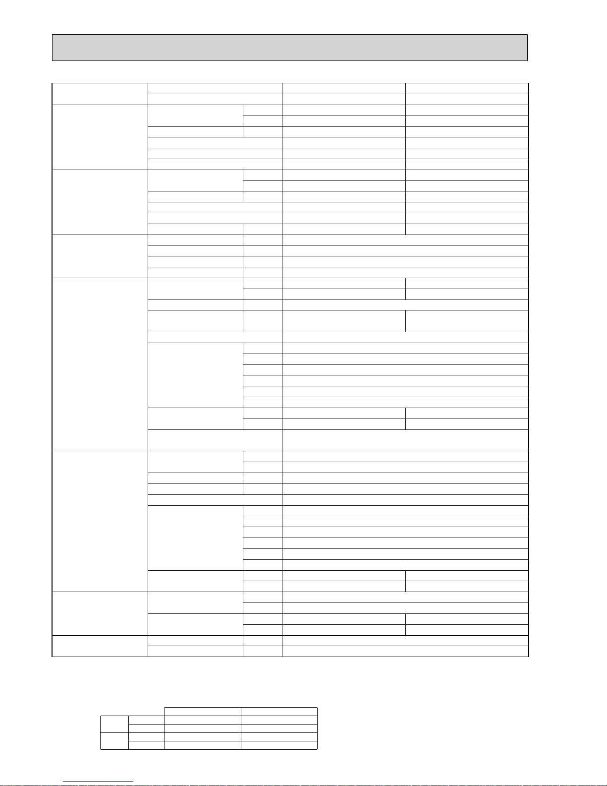
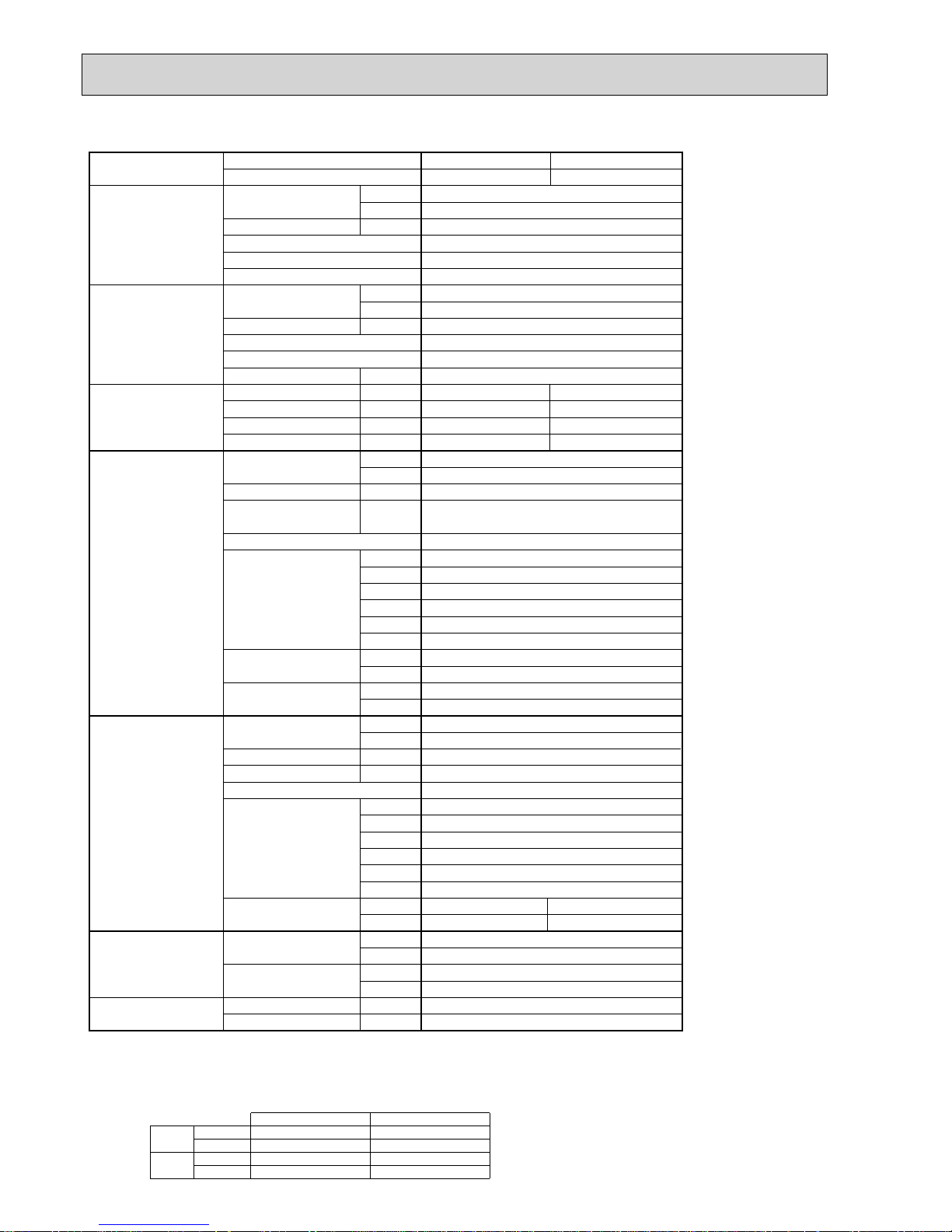
NOTE: 1. Rating conditions (ISO T1)
Cooling Indoor : D.B. 27 (80°F) W.B. 19 (66°F) Outdoor : D.B. 35 (95°F) W.B. 24 (75°F)
Heating Indoor : D.B. 20 (68°F) Outdoor : D.B. 7 (45°F) W.B. 6 (43°F)
Refrigerant piping length (one way) : 5m (16ft.)
2. Guaranteed operating range
Indoor Outdoor
Cooling
Upper limit
D.B. 35°C, W.B. 22.5°C
D.B. 46
Lower limit
D.B. 19°C, W.B. 15°C D.B. -5 +
Heating
Upper limit
D.B. 28°C
D.B. 21, W.B. 15
Lower limit
D.B. 17°C
D.B. -15, W.B. -15
4. Above data are based on the indicated voltage.
+ If optional air protect guide is installed : D.B.-15
Indoor unit Single phase 230V 50Hz
Single phase 230V 50Hz
Outdoor unit
3. Guaranteed voltage
198~264V, 50Hz
Model name Indoor unit PCA-RP100KA PCA-RP125KA PCA-RP140KA
Outdoor unit PUHZ-P100VHA3 PUHZ-P125VHA3 PUHZ-P140VHA3
Cooling Capacity Btu/h 32,100 42,000 46,400
kW 9.4(4.9-11.2
)
12.3(5.5-14.0
)
13.6(5.5-15.0
)
Total input kW 3.13 4.09 4.84
EER 3.00 3.01 2.81
Energy label class C B C
SHF 0.77 0.72 0.71
Heating Capacity Btu/h 38,200 47,800 54,600
kW 11.2(4.5-12.5
)
14.0(5.0-16.0
)
16.0(5.0-18.0
)
Total input kW 3.28 4.12 4.69
COP 3.41 3.40 3.41
Energy label class B C B
Booster heater kW - - -
Power supply Phase W 1
Cycle Hz 50
Voltage V 230
Breaker size A 32 40
Indoor unit Air flow CMM 22 - 24 - 26 - 28 23 - 25 - 27 - 29
(
Low-Medium2-Medium1-High
)
CFM 775-850-920-990 810-885-955-1025
External pressure Pa 0
Sound level dB(A
)
37 - 39 - 41 - 43 39 - 41 - 43 - 45 41 - 43 - 45 - 48
(
Low-Medium2-Medium1-High
)
External finish White Munsell 6.4Y 8.9/0.4
Dimension W : mm 1600
D : mm 680
H : mm 230
W : inch 63
D : inch 26-3/4
H : inch 9-1/16
Weight kg 36 38 39
lbs 79 84 86
Field drain pipe O.D. mm 26
inch 1
Outdoor unit Air flow CMM 60 100
CFM 2,120 3,530
Sound level at cooling dB(A
)
50 51 52
Sound level at heating dB(A
)
54 55 56
External finish Ivory Munsell 3Y 7.8/1.1
Dimension W : mm 950
D : mm 330
H : mm 943 1350
W : inch 37-3/8
D : inch 13 + 1-3/16
H : inch 37-1/8 53-1/8
Weight kg 75 99
lbs 165 218
Refrigerant pipe size Gas side O.D. mm 15.88
inch 5/8
Liquid side O.D. mm 9.52
inch 3/8
Refrigerant pipe length Height difference m Max. 30
Length m Max. 50
24 - 26 - 29 - 32
850-920-1025-1130
2-4. CEILING-SUSPENDED TYPE

11
Model name Indoor unit PCA-RP100KA PCA-RP125KA PCA-RP140KA
Outdoor unit PUHZ-P100YHA PUHZ-P125YHA PUHZ-P140YHA
Cooling Capacity Btu/h 32,100 42,000 46,400
kW 9.4(4.9-11.2
)
12.3(5.5-14.0
)
13.6(5.5-15.0
)
Total input kW 3.13 4.09 4.84
EER 3.00 3.01 2.81
Energy label class C B C
SHF 0.77 0.72 0.71
Heating Capacity Btu/h 38,200 47,800 54,600
kW 11.2(4.5-12.5
)
14.0(5.0-16.0
)
16.0(5.0-18.0
)
Total input kW 3.28 4.12 4.69
COP 3.41 3.40 3.41
Energy label class B C B
Booster heater kW - - -
Power supply Phase W 3
Cycle Hz 50
Voltage V 400
Breaker size A
16
Indoor unit Air flow CMM
(
Low-Medium2-Medium1-High
)
CFM
External pressure Pa 0
Sound level dB(A
)
37 - 39 - 41 - 43 39 - 41 - 43 - 45 41 - 43 - 45 - 48
(
Low-Medium2-Medium1-High
)
External finish
Dimension W : mm 1600
D : mm 680
H : mm 230
W : inch
D : inch 26-3/4
H : inch
Weight kg 36 38 39
lbs 79 84 86
Field drain pipe O.D. mm 26
inch 1
Outdoor unit Air flow CMM 60 100
CFM 2,120 3,530
Sound level at cooling dB(A
)
50 51 52
Sound level at heating dB(A
)
54 55 56
External finish
Dimension W : mm 950
D : mm 330 (+30)
H : mm 943 1350
W : inch 37-3/8
D : inch 13 + 1-3/16
H : inch 37-1/8 53-1/8
Weight kg 77 101
lbs 169 222
Refrigerant pipe size Gas side O.D. mm 15.88
inch 5/8
Liquid side O.D. mm 9.52
inch 3/8
Refrigerant pipe length Height difference m Max. 30
Length m Max. 50
22 - 24 - 26 - 28 23 - 25 - 27 - 29
775-850-920-990 810-885-955-1025
White Munsell 6.4Y 8.9/0.4
63
9-1/16
Ivory Munsell 3Y 7.8/1.1
24 - 26 - 29 - 32
850-920-1025-1130
NOTE: 1. Rating conditions (ISO T1)
Cooling Indoor : D.B. 27 (80°F) W.B. 19 (66°F) Outdoor : D.B. 35 (95°F) W.B. 24 (75°F)
Heating Indoor : D.B. 20 (68°F) Outdoor : D.B. 7 (45°F) W.B. 6 (43°F)
Refrigerant piping length (one way) : 5m (16ft.)
2. Guaranteed operating range
Indoor Outdoor
Cooling
Upper limit
D.B. 35°C, W.B. 22.5°C
D.B. 46°C
Lower limit
D.B. 19°C, W.B. 15°C D.B. -5°C +
Heating
Upper limit
D.B. 28°C
D.B. 21°C, W.B. 15°C
Lower limit
D.B. 17°C
D.B. -15°C, W.B. -15°C
4. Above data are based on the indicated voltage.
Indoor unit Single phase 230V 50Hz
3 phase 400V 50Hz
Outdoor unit
Indoor unit 198~264V, 50Hz
342~457V, 50Hz
Outdoor unit
3. Guaranteed voltage
+ If optional air protect guide installed. D.B.-15
12
Model name Indoor unit PCA-RP125HA
Outdoor unit PUHZ-P125VHA3
Cooling Capacity Btu/h 42,000
kW 12.3(5.5-14.0
)
Total input kW 4.38
EER 2.81
Energy label class C
SHF 0.78
Heating Capacity Btu/h 47,100
kW 13.8(5.0-16.0
)
Total input kW 4.30
COP 3.21
Energy label class C
Booster heater kW -
Power supply Phase W 1
Cycle Hz 50
Voltage V 230
Breaker size A 32
Indoor unit Air flow CMM 30-38
(
Low-High
)
CFM 1060-1350
External pressure Pa 0
Sound level dB(A
)
44-50
(
Low-High
)
External finish Stainless steel
Dimension W : mm 1520
D : mm 650
H : mm 280
W : inch 59-7/8
D : inch 25-5/8
H : inch 11
Weight kg 56
lbs 124
Field drain pipe O.D. mm 26
inch 1
Outdoor unit Air flow CMM 100
CFM 3,530
Sound level at cooling dB(A
)
51
Sound level at heating dB(A
)
55
External finish Ivory Munsell 3Y 7.8/1.1
Dimension W : mm 950
D : mm 330+30
H : mm 1350
W : inch 37-3/8
D : inch 13 + 1-3/16
H : inch 53-1/8
Weight kg 99
lbs 218
Refrigerant pipe size Gas side O.D. mm 15.88
inch 5/8
Liquid side O.D. mm 9.52
inch 3/8
Refrigerant pipe length Height difference m Max. 30
Length m Max. 50
PCA-RP125HA
PUHZ-P125YHA
3
50
400
16
101
222
NOTE: 1. Rating conditions (ISO T1)
Cooling Indoor : D.B. 27 (80°F) W.B. 19 (66°F) Outdoor : D.B. 35 (95°F) W.B. 24 (75°F)
Heating Indoor : D.B. 20 (68°F) Outdoor : D.B. 7 (45°F) W.B. 6 (43°F)
Refrigerant piping length (one way) : 5m (16ft.)
2. Guaranteed operating range
Indoor Outdoor
Cooling
Upper limit
D.B. 35°C, W.B. 22.5°C
D.B. 46°C
Lower limit
D.B. 19°C, W.B. 15°C D.B. -5°C +
Heating
Upper limit
D.B. 28°C
D.B. 21°C, W.B. 15°C
Lower limit
D.B. 17°C
D.B. -15°C, W.B. -15°C
4. Above data are based on the indicated voltage.
+ If optional air protect guide installed. D.B.-15
Indoor unit Single phase 230V 50Hz
V: Single phase 230V 50Hz
,
Y: 3 phase 400V 50Hz
Outdoor unit
3. Guaranteed voltage
198~264V, 50Hz (P125Y : 342~457V, 50Hz)
13
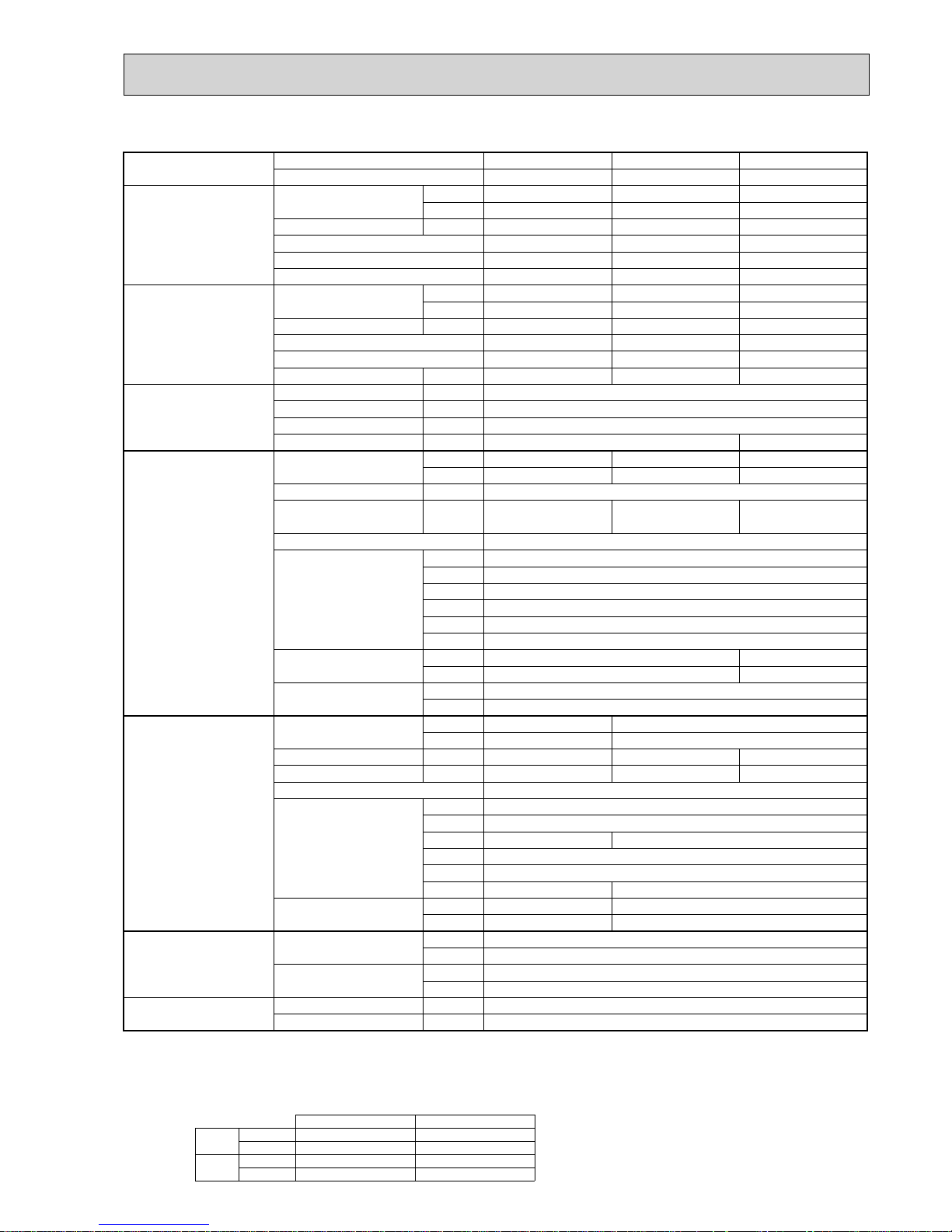
NOTE: 1. Rating conditions (ISO T1)
Cooling Indoor : D.B. 27 (80°F) W.B. 19 (66°F) Outdoor : D.B. 35 (95°F) W.B. 24 (75°F)
Heating Indoor : D.B. 20 (68°F) Outdoor : D.B. 7 (45°F) W.B. 6 (43°F)
Refrigerant piping length (one way) : 5m (16ft.)
2. Guaranteed operating range
Indoor Outdoor
Cooling
Upper limit
D.B. 35°C, W.B. 22.5°C
D.B. 46
Lower limit
D.B. 19°C, W.B. 15°C D.B. -5 +
Heating
Upper limit
D.B. 28°C
D.B. 21, W.B. 15
Lower limit
D.B. 17°C
D.B. -15, W.B. -15
4. Above data are based on the indicated voltage.
+ If optional air protect guide is installed : D.B.-15
Indoor unit Single phase 230V 50Hz
Single phase 230V 50Hz
Outdoor unit
3. Guaranteed voltage
198~264V, 50Hz
Model name Indoor unit PSA-RP100GA PSA-RP125GA PSA-RP140GA
Outdoor unit PUHZ-P100VHA3 PUHZ-P125VHA3 PUHZ-P140VHA3
Cooling Capacity Btu/h 32,100 42,000 46,400
kW 9.4(4.9-11.2
)
12.3(5.5-14.0
)
13.6(5.5-15.0
)
Total input kW 3.12 4.38 5.64
EER 3.01 2.81 2.41
Energy label class B C E
SHF 0.83 0.76 0.75
Heating Capacity Btu/h 38,200 47,800 54,600
kW 11.2(4.5-12.5
)
14.0(5.0-16.0
)
16.0(5.0-18.0
)
Total input kW 3.28 4.98 5.69
COP 3.41 2.81 2.81
Energy label class B D D
Booster heater kW - - -
Power supply Phase W 1
Cycle Hz 50
Voltage V 230
Breaker size A 32 40
Indoor unit Air flow CMM 24-31 26-33 27-35
(
Low-High
)
CFM 850-1060 920-1165 955-1240
External pressure Pa 0
Sound level dB(A
)
44-49 46-51 47-52
(
Low-High
)
External finish White Munsell 0.70Y 8.59/0.97
Dimension W : mm 600
D : mm 350
H : mm 1900
W : inch 23-5/8
D : inch 13-3/4
H : inch 74-13/16
Weight kg 51 53
lbs 112 117
Field drain pipe I.D. mm 20
inch 13/16
Outdoor unit Air flow CMM 60 100
CFM 2,120 3,530
Sound level at cooling dB(A
)
50 51 52
Sound level at heating dB(A
)
54 55 56
External finish Ivory Munsell 3Y 7.8/1.1
Dimension W : mm 950
D : mm 330+30
H : mm 943 1350
W : inch 37-3/8
D : inch 13 + 1-3/16
H : inch 37-1/8 53-1/8
Weight kg 75 99
lbs 165 218
Refrigerant pipe size Gas side O.D. mm 15.88
inch 5/8
Liquid side O.D. mm 9.52
inch 3/8
Refrigerant pipe length Height difference m Max. 30
Length m Max. 50
2-5. FLOOR STANDING TYPE
14
Model name Indoor unit PSA-RP100GA PSA-RP125GA PSA-RP140GA
Outdoor unit PUHZ-P100YHA PUHZ-P125YHA PUHZ-P140YHA
Cooling Capacity Btu/h 32,100 42,000 46,400
kW 9.4(4.9-11.2
)
12.3(5.5-14.0
)
13.6(5.5-15.0
)
Total input kW 3.12 4.38 5.64
EER 3.01 2.81 2.41
Energy label class B C E
SHF 0.83 0.76 0.75
Heating Capacity Btu/h 38,200 47,800 54,600
kW 11.2(4.5-12.5
)
14.0(5.0-16.0
)
16.0(5.0-18.0
)
Total input kW 3.28 4.98 5.69
COP 3.41 2.81 2.81
Energy label class B D D
Booster heater kW - - -
Power supply Phase W 3
Cycle Hz 50
Voltage V 400
Breaker size A 16
Indoor unit Air flow CMM 24-31 26-33 27-35
(
Low-High
)
CFM 850-1060 920-1165 955-1240
External pressure Pa 0
Sound level dB(A
)
44-49 46-51 47-52
(
Low-High
)
External finish White Munsell 0.70Y 8.59/0.97
Dimension W : mm 600
D : mm 350
H : mm 1900
W : inch 23-5/8
D : inch 13-3/4
H : inch 74-13/16
Weight kg 51 53
lbs 112 117
Field drain pipe I.D. mm 20
inch 13/16
Outdoor unit Air flow CMM 60 100
CFM 2,120 3,530
Sound level at cooling dB(A
)
50 51 52
Sound level at heating dB(A
)
54 55 56
External finish Ivory Munsell 3Y 7.8/1.1
Dimension W : mm 950
D : mm 330+30
H : mm 943 1350
W : inch 37-3/8
D : inch 13 + 1-3/16
H : inch 37-1/8 53-1/8
Weight kg 77 101
lbs 169 222
Refrigerant pipe size Gas side O.D. mm 15.88
inch 5/8
Liquid side O.D. mm 9.52
inch 3/8
Refrigerant pipe length Height difference m Max. 30
Length m Max. 50
NOTE: 1. Rating conditions (ISO T1)
Cooling Indoor : D.B. 27 (80°F) W.B. 19 (66°F) Outdoor : D.B. 35 (95°F) W.B. 24 (75°F)
Heating Indoor : D.B. 20 (68°F) Outdoor : D.B. 7 (45°F) W.B. 6 (43°F)
Refrigerant piping length (one way) : 5m (16ft.)
2. Guaranteed operating range
Indoor Outdoor
Cooling
Upper limit
D.B. 35°C, W.B. 22.5°C
D.B. 46°C
Lower limit
D.B. 19°C, W.B. 15°C D.B. -5°C +
Heating
Upper limit
D.B. 28°C
D.B. 21°C, W.B. 15°C
Lower limit
D.B. 17°C
D.B. -15°C, W.B. -15°C
4. Above data are based on the indicated voltage.
Indoor unit Single phase 230V 50Hz
3 phase 400V 50Hz
Outdoor unit
Indoor unit 198~264V, 50Hz
342~457V, 50Hz
Outdoor unit
3. Guaranteed voltage
+ If optional air protect guide installed. D.B.-15
1515
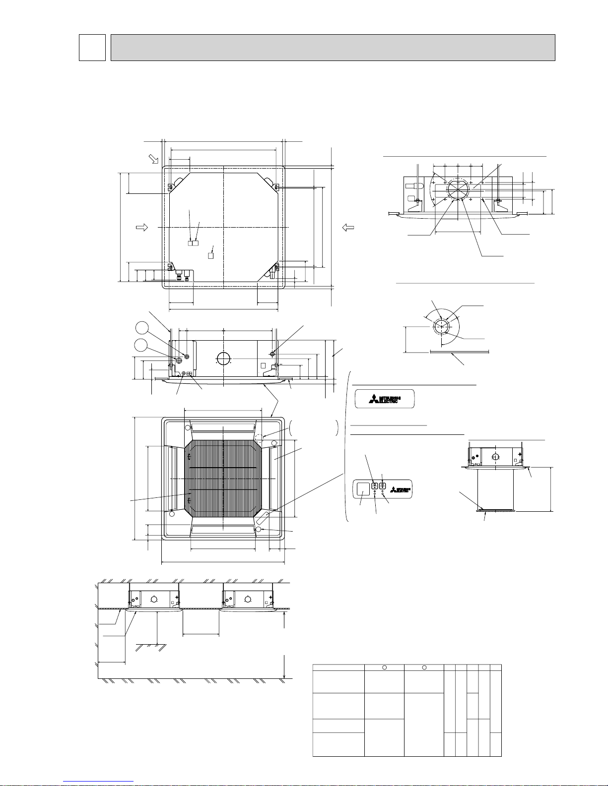
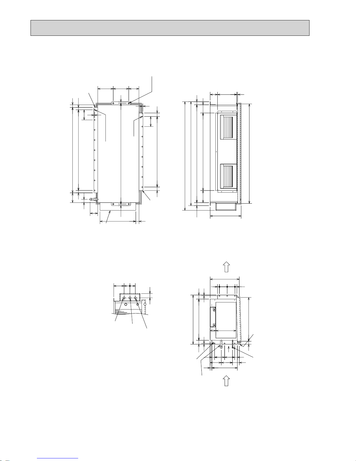
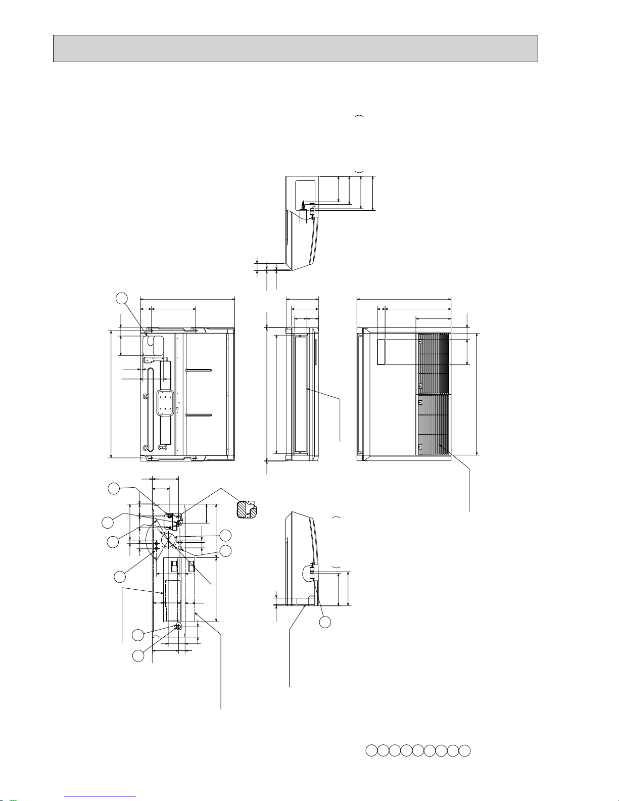
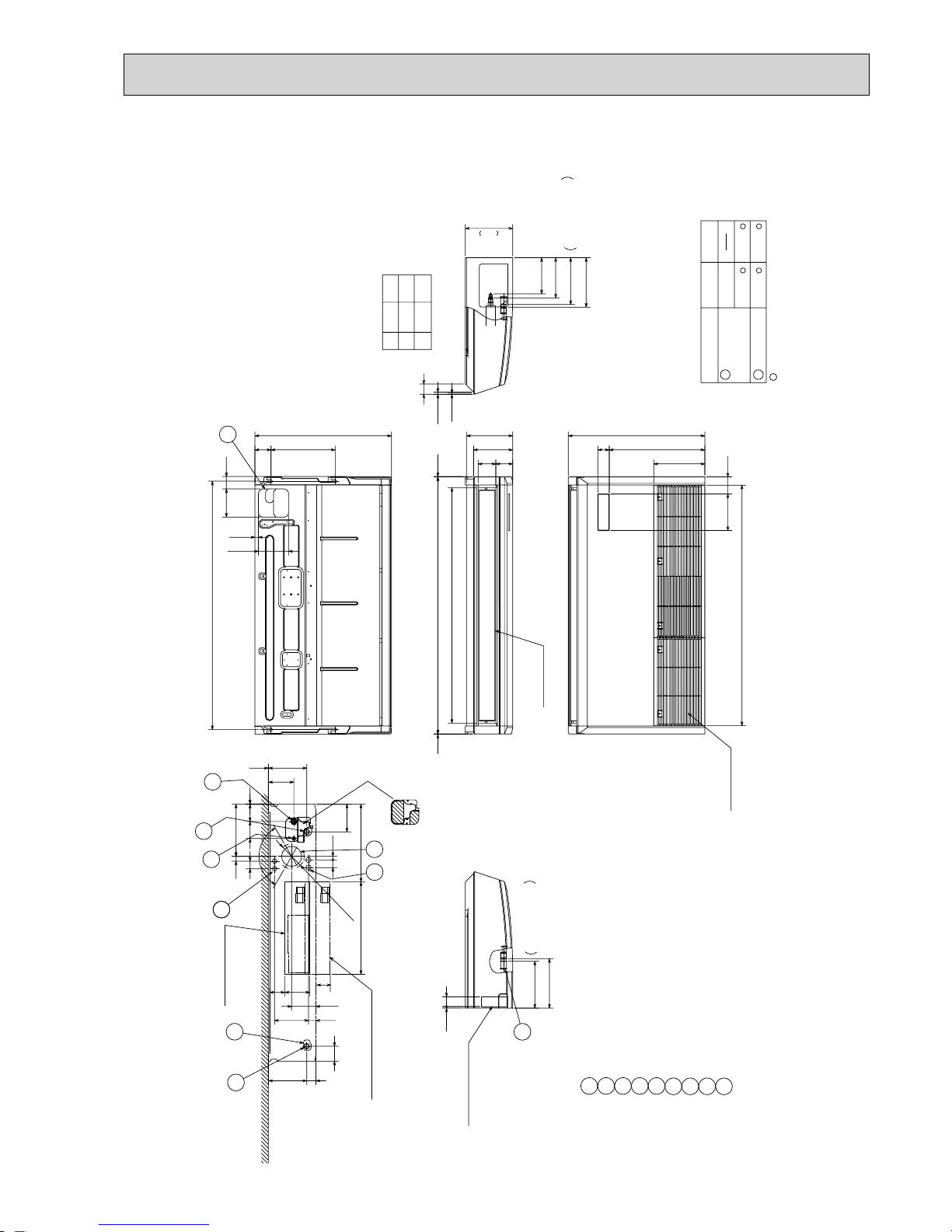
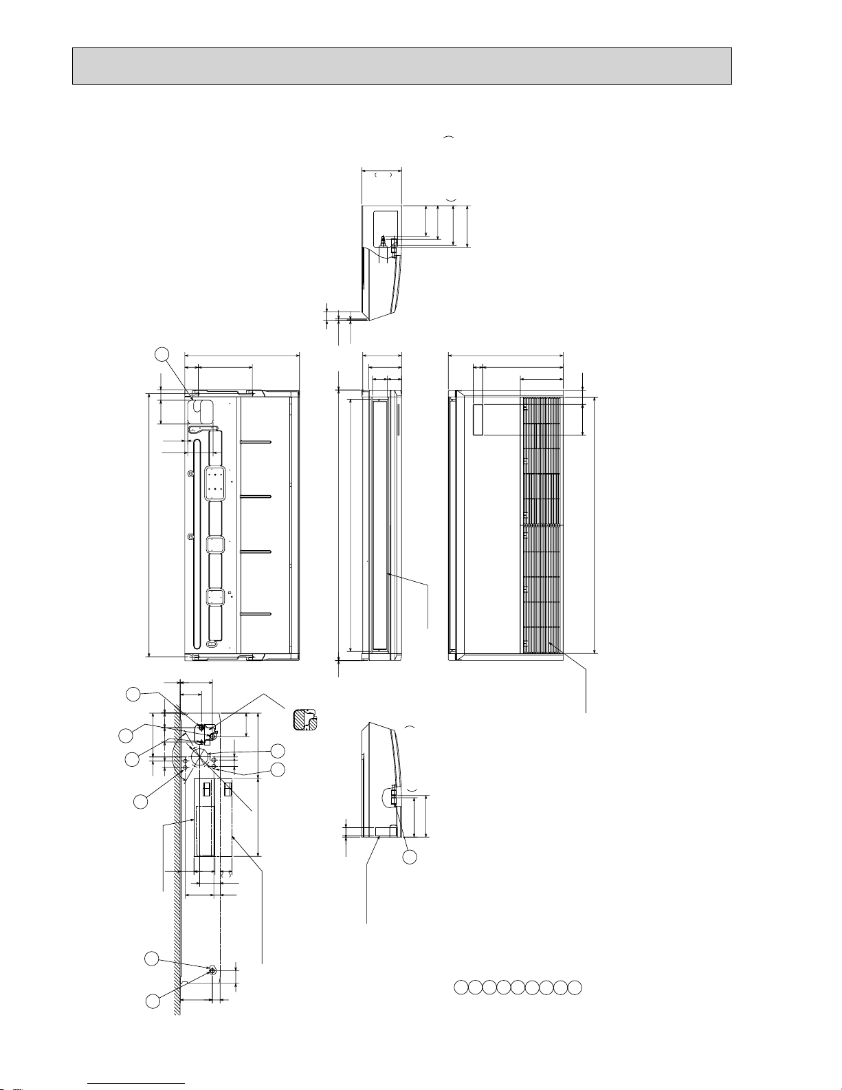
3
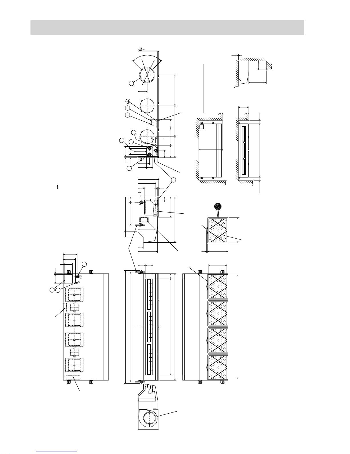
OUTLINES AND DIMENSIONS
Unit : mm
Note 1. Please choose the grille from a standard grille, auto-grille.
2. As for drain pipe, please use VP-25(O.D. :32 PVC TUBE).
Drain pump is included.
Max. lifting height is 850mm from the ceiling.
3. As for suspension bolt, please use M10 or W3/8.
(Procured at local site)
4. Electrical box may be removed for the service purpose.
Make sure to slack the electrical wire little bit for control/ power wires connection.
5. The height of the indoor unit is able to be adjusted with the grille attached.
6. For the installation of the optional high efficiency filter or optional multi-functional casement.
1) Requires E or more space between transom and ceiling for the installation.
2) Add 135 mm to the dimensions + marked on the figure.
3) The optional high efficiency filter must be used jointly with optional multi-functional casement.
7. When installing the branch ducts, be sure to insulate adequately.
Otherwise condensation and dripping may occur.
(It becomes the cause of dew drops/water dew.)
8. As for necessary installation/service space, please refer to the left figure.
Ceiling
Grille
Indoor unit
1500mm
or more
1000mm
or more
3000mm or more
1800mm or more
from floor
For high
attachment
Indoor unit
Obstacle
Floor
Ceiling
Air intake grille
Max. 4.0m
L.L Filter
37728460
()
Ceiling hole
Branch duct hole
Drain pipe
connected to VP-25
Ceiling
Grille
Drain hole
Models
Auto vane
(Air outlet)
Air intake grille
Ceiling
Cut out hole
Cut out hole
Cut out hole
Burring hole pitch
Burring hole pitch
Burring hole
Burring hole
Power supply wire,
Indoor unit/Outdoor unit
connecting wire entry
Indoor unit/Outdoor unit
connecting terminal block
Indoor power supply
terminal block(Option part)
Control wire entry
Air intake hole
Air intake hole
Air outlet hole
Air outlet hole
Connected the
attached socket.
Keep approximately
10 to 15mm space
between unit ceiling
and ceiling slab.
Branch duct hole
Fresh air
intake hole
Ceiling hole
Suspension bolt pitch
Suspension bolt pitch
Remote controller
terminal block
Suspension bolt
M10 or W3/8
(7.5)(7.5)
605
+35
- 5
620
DEFROST/STAND BY lamp
Receiver
Operation lamp
In case of standard grille : PLP-6BA / PLP-6BAMD
In case of wireless remote controller : PLP-6BALM Auto grille
Air intake grille up/down discharge
Emergency operation
switch<Cooling>and
Emergency Up/Down switch<Up>
160
160
500
500
597
83 36
950
8336
950
597
A
17
+5
0
B35
190
156
105
140
50~70
160
840
150
90
C
D
840
187.5
20~45
860~910
20~45
810
20~45
860~910
20~45
24
160
++
+
+
+
+
+
+
+
M
M
M
M
120°
120°
:175
:125
167
158
Vane motor
2
1
Drain pump clean hole
and Drain emergency
drainage hole
130
100
70°
155
350
90 100 100 90
BACDE
241 258
80
87
74
400
298
85 77
440
281
2
1
Refrigerant pipe
···:6.35
Flared connection
···1/4 inch
Refrigerant pipe
···:9.52
Flared connection
···3/8 inch
Refrigerant pipe
···:12.7
Flared connection
···1/2 inch
Refrigerant pipe
···:15.88
Flared connection
···5/8 inch
Refrigerant pipe
:6.35 / :9.52
Flared connection
1/4 inch/3/8 inch
(compatible)
PLA-RP50BA
PLA-RP60BA
PLA-RP71BA
PLA-RP71BA2
PLA-RP100,125BA
PLA-RP100BA3
PLA-RP125,140BA2
Detail drawing of fresh air intake hole
Detail connecting of branch duct(Both aspects)
3-:2.8
14-:2.8
:150
:100
Emergency operation
switch<Heating>and
Emergency Up/Down switch<Down>
In case of auto-grille : PLP-6BAJ
Suspension bolt
lower edge
170
+
INDOOR UNIT
PLA-RP50BA PLA-RP60BA PLA-RP71BA
PLA-RP100BA PLA-RP125BA
PLA-RP71BA2 PLA-RP100BA3 PLA-RP125BA2 PLA-RP140BA2
16
Unit : mm
PEAD-RP50, 60, 71, 100, 125, 140JA
Air Filter
Suspension bolt hole
4-14x30 Slot
Air
outlet
Air
inlet
2xE-
:
2.9
2×2-:2.9
Refrigerant piping
Flare connection (liquid)
2
1
Refrigerant piping
Flare connection (gas)
Drain pump
Control box
Terminal block
(Indoor/Outdoor connecting line)
Terminal block
(Remote controller transmission line)
Drain pipe(O.D.:32)
(Spontaneous draining)
Drain pipe
(O.D.:32)
:15.88
:9.52
:6.35
:12.7
Liquid pipe
Gas pipe
1558
1358
1500
1300
Model A
1200
900 954 860 9
E11D
1060
C
110 0B1154
PEAD-RP140JA
PEAD-RP100,125JA
PEAD-RP60,71JA
PEAD-RP50JA
1400
1600
1454
1654
1500
1700
1360
15601416
1000
1000
F
858800
G
1058
40
21018
G21
250
12233
15
58
57
10
100
100x(E-1)=F
A
B(Suspension bolt pitch)
C
23
643 (Suspension bolt pitch)
30
57
20
D (Duct)
178 (Duct)
40
23
10
238
32 700
732
136
67
356
100
41
217
NOTE 1. Use M10 screw for the Suspension bolt (field supply).
2. Keep the service space for the maintenance at the bottom.
3. This chart indicates for PEAD-RP60
•71•
100•125•140JA
models,which have 2 fans. PEAD-RP50JA models have 1 fan.
4. In case that the inlet duct is used, remove the air filter (supplied with
the unit), then install the filter (field supply) at suction side.
Less than 300mm
175±5mm
Less than 700mm
Drain hose (I.D.:32)
<accessory>
(Actual length)
1520
1320
1020
819
JQS
340
R
54 260 4 780 10 40.5 273 4
440
P10N
990
M4L49K
330
5
5380
5454320
37055
1280
148012124040
330
1700
1500
PEAD-RP50JA
PEAD-RP60,71JA
PEAD-RP100,125JA
PEAD-RP140JA
1200
1000
HModel
N-
:
2.9
K
Kx(L-1)=M
J
112 112
11
Q
Qx(R-1)=SP
J
6
More than 20mm
More than 10mm
Make the access door at the appointed position properly for service maintenance.
Ceiling surface
Access door
50
250~300
450
50
H
777
450
More than 300
Access door
Note2
Required space for service and maintenance
17
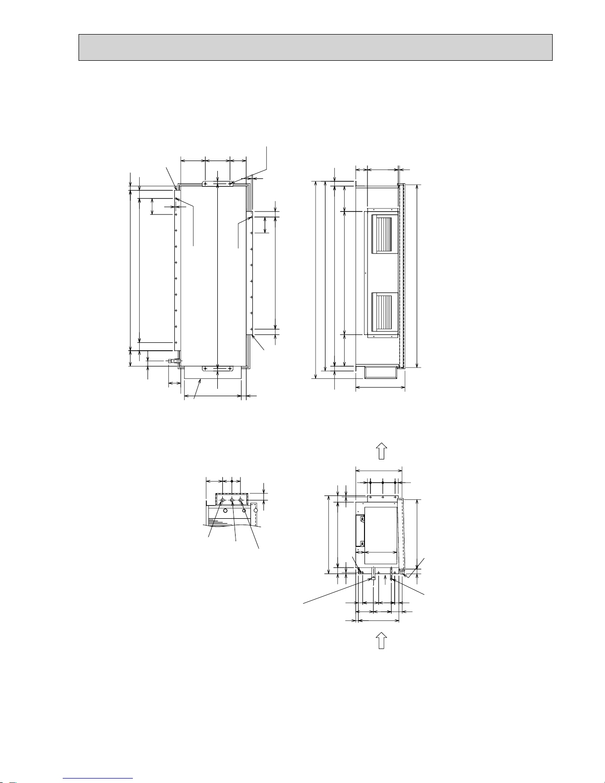
Unit : mm
PEAD-RP50, 60, 71, 100, 125, 140JAL
Air Filter
:15.88
:9.52
:6.35
:12.7
Liquid pipe
Gas pipe
1558
1358
1500
1300
Model A
1200
900 954 860 9
E11D
1060
C
110 0B115 4
PEAD-RP140JAL
PEAD-RP100,125JAL
PEAD-RP60,71JAL
PEAD-RP50JAL
1400
1600
1454
1654
1500
1700
1360
15601416
1000
1000
F
858800
G
1058
40
21018
G
21
15
58
NOTE 1. Use M10 screw for the Suspension bolt (field supply).
2. Keep the service space for the maintenance at the bottom.
3. This chart indicates for PEAD-RP60
•71•
100•125•140JAL
models,which have 2 fans. PEAD-RP50JAL models have 1 fan.
4. In case of the inlet duct is used,remove the air filter
(supplied with the unit), then install the filter
(field supply) at suction side.
1520
1320
1020
819
JQS
340
R
54 260 4 780 10 40.5 273 4
440
P10N
990
M4L49K
330
5
5380
5454320
37055
1280
148012124040
330
1700
1500
PEAD-RP50JAL
PEAD-RP60,71JAL
PEAD-RP100,125JAL
PEAD-RP140JAL
1200
1000
HModel
N-
:
2.9
K
Kx(L-1)=M
J
112 112
11
Q
Qx(R-1)=SP
J
6
More than 20mm
More than 10mm
Make the access door at the appointed position properly for service maintenance.
Ceiling surface
Access door
50
250~300
450
50
H
777
450
More than 300
Access door
Note2
Required space for service and maintenance
Suspension bolt hole
4-14x30 Slot
Air
outlet
Air
inlet
2xE-:2.9
57
10
100
100x(E-1)=F
A
B(Suspension bolt pitch)
C
23
643 (Suspension bolt pitch)
30
57
20
D (Duct)
Drain pipe(O.D.:32)
2×2-
:
2.9
Refrigerant piping
Flare connection (liquid)
2
1
Refrigerant piping
Flare connection (gas)
Control box
Terminal block
(Indoor/Outdoor connecting line)
Terminal block
(Remote controller transmission line)
250
33
122
178 (Duct)
40
23
10
32 700
732
136
67
356
100
217
175±5mm
<accessory>
Drain hose (I.D.
:
32)
(Actual length)
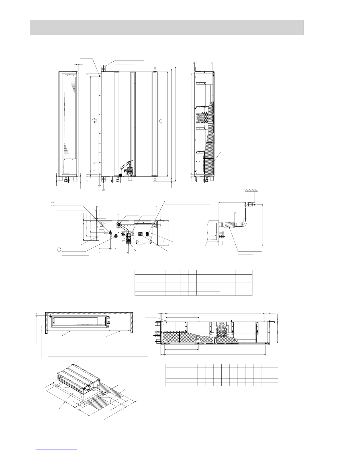
18
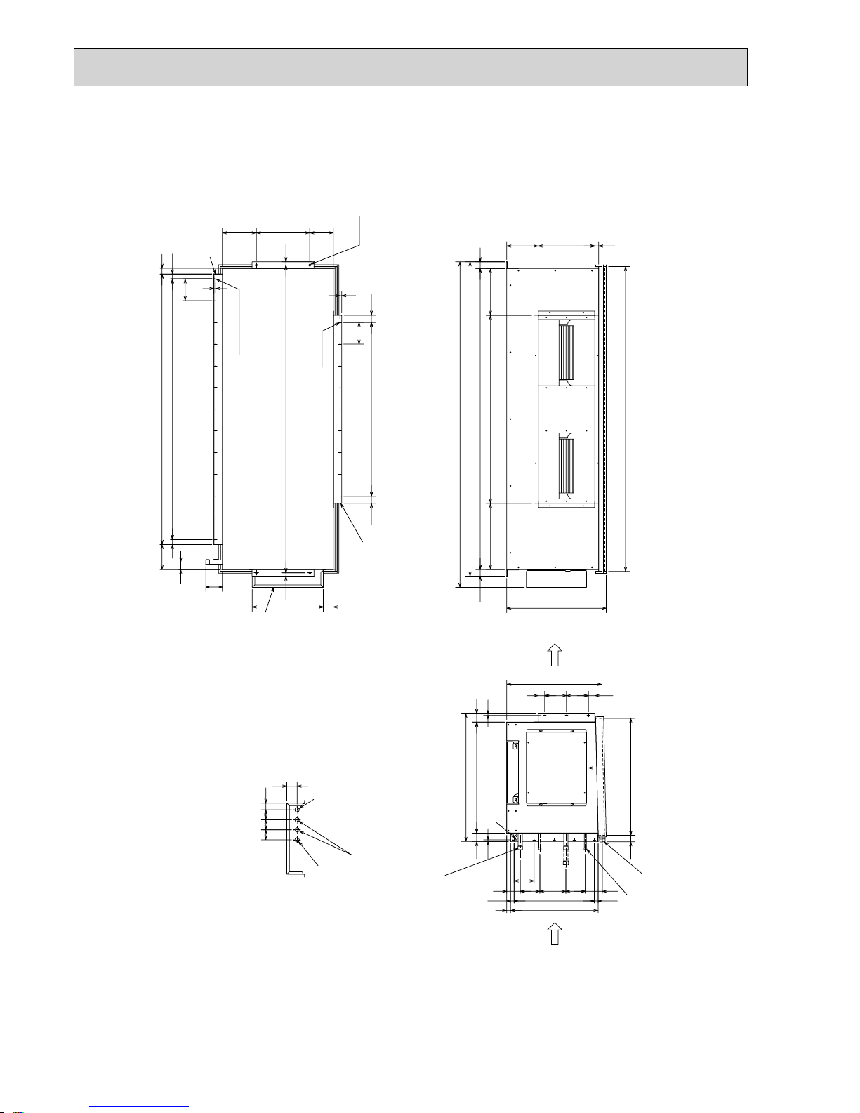
PEA-RP200GA Unit : mm
Return air
sensor
A
Rubber bush <Remote
controller wiring>
Rubber bush
<Outdoor unit
connection wiring>
Rubber bush
<Power supply wiring>
A
4- :12
Drain R1
Top vie w
Control box
Return air
duct flange
Supply air
duct flange
<For hanging bolt M10>
[Field supply]
22-: 3.1
24-: 3 Holes
Refrigerant pipe
:9.52 (3/8 braze)
Refrigerant pipe
:25.4 (1 braze)
<Accessory>
Pipe cover···················2pcs.
(For dew condensation prevention of local piping and unit connection)
Remote controller········1pc.
Return air
Left side view
Supply air
Front view
75
55
12970
42
124 34
131
530
50
9525011
7x130(=910)
10
130
130
45
45
31 31
1102
200
10
8x130(=1040)
1300
20
199
100
40
20
462
144
1284
400
155 1000 105
40 1260 40
1340
1400
56539
22330
145
89
35
130
130
35
634
262 73
10
54
10
376
2510010025
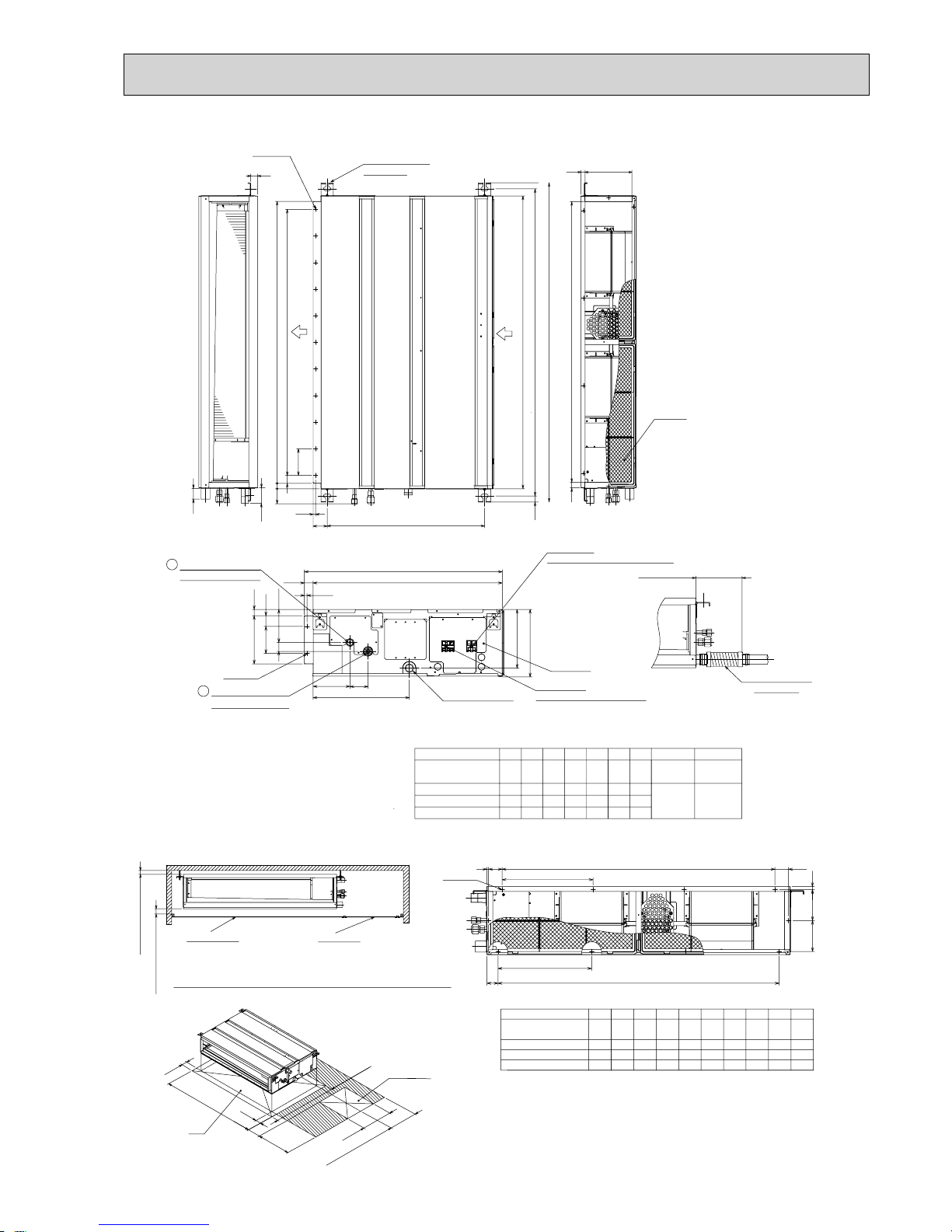
19
PEA-RP250GA Unit : mm
Rubber bush <Remote
controller wiring>
Rubber bush
<Outdoor unit
connection wiring>
Rubber bush
<Power supply
wiring>
A
A
4- :12
Drain R1
Top view
Control box
22- :3.1
<For hanging bolt M10>
[Field supply]
Return air
duct flange
Supply air
duct flange
26- :3 Holes
Left side view
Supply air
Return air
Front view
Return air
sensor
<Accessory>
Pipe cover··················2pcs.
(For dew condensation prevention of local piping and unit connection)
Remote controller·······1pc.
Refrigerant pipe
:12.7 (1/2 braze)
Refrigerant pipe
:25.4 (1 braze)
42
144145
755570 129
124
131
50 530
34
130
9525011
10
66
1302
1484
7x130(=910)
130
45
45
200
20
100
20
199
40
1500
462
66 9X130(=1170)
10
25 100 100 25
10 10
1540
40146040
255 205
376
1000
1600
73262
400
39 565
54
634
35
130
89
330 22
130
35
20
PEA-RP400, 500GA Unit : mm
45
Refrigerant pipe
PEA-RP400GA :
:
9.52 (3/8 braze)
PEA-RP500GA :
:
12.7 (1/2 braze)
[2 places (*2 part)]
*2*1*2
*1
Refrigerant pipe :25.4 (1 braze)
[2 places (*1 part)]
Return air sensor
(2 places)
Drain R1
24-:3.1
36-:3 HOLES
Left side view
Front view
Top view
Return air
Supply air
4-:15
<For hanging bolt M12>
[Field supply]
Return air duct flange
Control box
Supply air duct flange
A
Rubber bush
<Remote controller wiring>
Rubber bush
<Power supply wiring>
Rubber bush
<Outdoor unit connection wiring>
A
<Accessory>
Pipe cover··················4pcs.
(For dew condensation prevention of local piping and unit connection)
Remote controller·······1pc.
81
11715611 7
10
20 1840
10
40
60
60
61
60
4040
1800
1880
50 664
525
22
102
22.5
120
4X120(=480)
22.5
595
1824
50
764
2801125395
340 18822
1947
570
40 130 130 40
10
33
29
130
12X130(=1560)
29
149 1618
100
42.5
130
8X130(=1040)42.5
10
203320141
20
42559
700
39
21
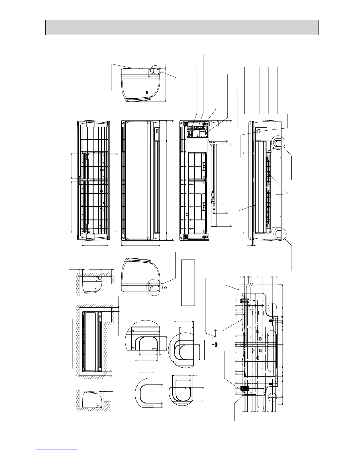
Min.7
Required space (Indoor unit)
Min.50
Min.220
Min.150
550mm or greater with optional
drain pump installation.
Min.250
Min.50
55mm or greater with left
or rear left pipng or drain
pump installation.
197
387
192
599
Top side
Front side
155
688
898
55
295
Front side (Grille open)
169
158
184
457 Gas pipe
539 Liquid pipe
610 Drain hose
Terminal block for outdoor unit
Terminal block for power supply (option)
Terminal block for
MA-remote controller (option)
Emergency operation switch
(cooling/heating)
Under side
Vane (auto)
Operation lamp
612
DEFROST/STAND BY lamp
Receiver
Knockout hole
for lower piping
Louver (manual)
Knockout hole
for lower piping
C
8
B
Size
Refrigerant pipe : :6.35
Flared connection : 1/4F
Refrigerant pipe : :12.7
Flared connection : 1/2F
:16 O.D
Liquid pipe
Gas pipe
Drain hose
Knockout hole
for right piping
Right side
Mount board
21.8020
32.7
53.5
66
128.5
153.5
231.5
273.2
449
281
193.5
180.3
278.3
167
140
115
0
174
213
238
394
449
253.5
232.5
203.5
178.5
166
103.5
91
78.5
116
41
28.5
16
0
372.3
356.3
327.5
291.5
265
225
200
125
70
15
0
15
70
125
200
225
265
238
291.5
327.5
372.3
356.3
Indoor unit outline
Mount board
4-:9 Bolt hole
77-:5.1
Tapping
screw hole
0
58
3.8
Center measurement hole :2.5
A
B
43
6
56
46
60
46
43
59
C
56
12.5
43
D
43
6
56
69
Knockout hole for piping
Knockout hole
for left piping
Left side
Sleeve
(purchased locally)
:65~:80
:65~:80
Through hole
249
A
5
250mm or greater with
optional drain pump
installation.
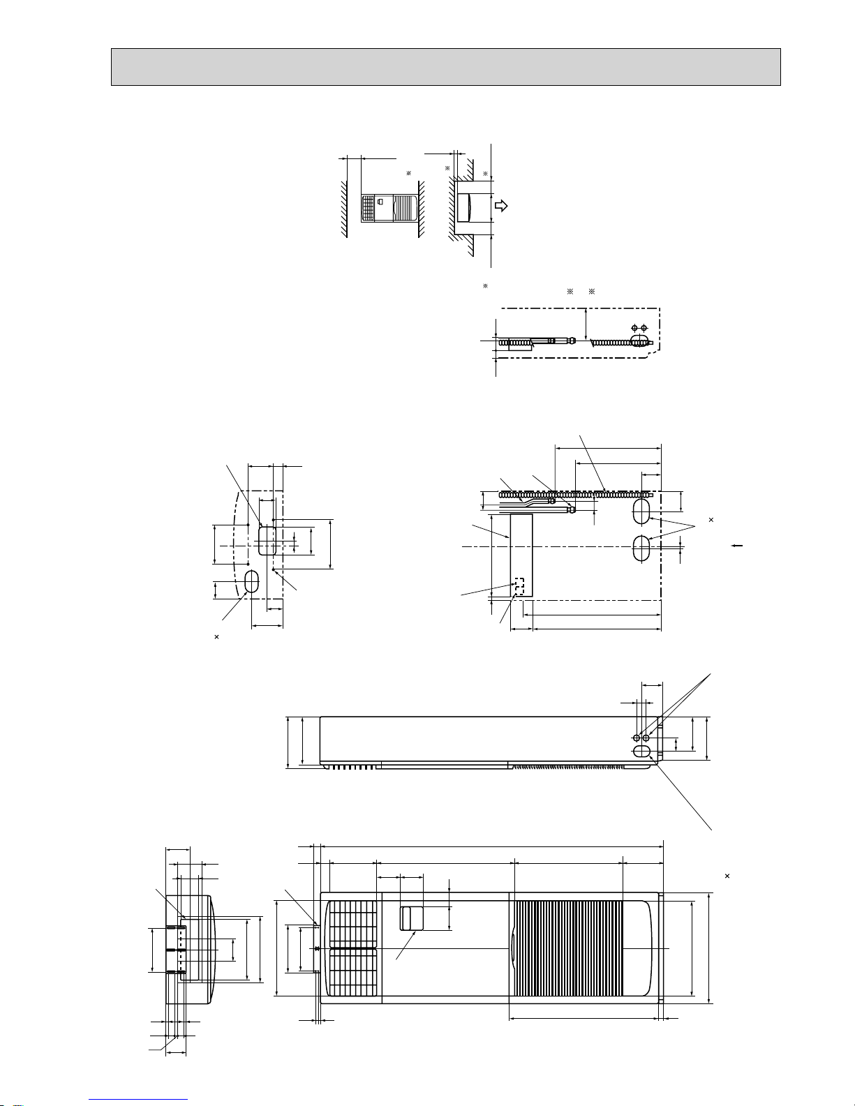
PKA-RP50HAL
Unit : mm
22
Unit : mm
PCA-RP50KA
(Drainage)
When drain socket
is installed
2
246
When drain socket
is installed
233
When electrical box
is pulled down
Electrical box
NOTES.
1.Use M10 or W3/8 screw for anchor bolt.
2.Please be sure when installing the
drain pump (option parts),
refrigerant pipe will be only upward.
Electrical box
233
Air outlet
Air intake
9
678
5
1
234
Knockout hole for upper drain pipe arrangement
Knockout hole for fresh air intake ø100
Knockout hole for wiring arrangement 2-ø22
Knockout hole for wiring arrangement 2-ø26
Drainage pipe connection(26mmI.D.)
Drainage pipe connection(for the left arrangement)
Knockout hole for left drain-piping arrangement
Refrigerant-pipe connection(gas pipe side/flared connection)
Refrigerant-pipe connection(liquid pipe side/flared connection)
1
In case of the rear pipe arrangement, make sure to
remove the shaded portions from the independent piece.
Then put the independent piece back in initial position.
(The heat exchanger might be clogged because of dust)
5
10
51
246
(Drainage)
(gas ø12.7)
(liquid ø6.35)
150
62140
18
917(Suspension bolt pitch)
320
680
80
84 88
195
230
57
254
476
680
182 85
878
8
48
260
24
38
85 86 2
126
169
121
190
18
38
120°
960 22
853
124 76
46
190
75
387461
3
8
Ceiling
5
1
4
7
184
203
ø125
6
9
37
138
2
[FRONT VIEW]
Accessory···Drain socket (I.D. 26)
(71)
23
Unit : mm
(Drainage)
When drain socket
is installed
2
246
When drain socket
is installed
233
Air intake
5
4
123
6
789
Knockout hole for upper drain pipe arrangement
Knockout hole for fresh air intake ø100
Knockout hole for wiring arrangement 2-ø22
Knockout hole for wiring arrangement 2-ø26
Drainage pipe connection(26mmI.D.)
Drainage pipe connection(for the left arrangement)
Knockout hole for left drain-piping arrangement
Refrigerant-pipe connection(gas pipe side/flared connection)
Refrigerant-pipe connection(liquid pipe side/flared connection)
NOTES.
1.Use M10 or W3/8 screw for anchor bolt.
2.Please be sure when installing the
drain pump (option parts),
refrigerant pipe will be only upward.
Air outlet
233
Electrical box
When electrical box
is pulled down
Electrical box
9
7
In case of the rear pipe arrangement, make sure to
remove the shaded portions from the independent piece.
Then put the independent piece back in initial position.
(The heat exchanger might be clogged because of dust)
5
10
51
246
A
B
236
150
62140
18
1237(Suspension bolt pitch)
320
680
80
84 88
195
230
57
254
476
680
182 85
1198
848
26024
38
85 86 2
126
16937
121
138
190 1
18
38
120°
1280 22
1173
124 76
46 190
75
387
461
2
3
8
5
1
4
ø125
6
8
[FRONT VIEW]
Ceiling
(Drainage)
(gas ø15.88)
(liquid )
Accessory···Drain socket (I.D. 26)
Flare nut ø6.35 (RP60 only)
A
B
60
179
203
71
180
200
5 LIQUID SIDE
4 GAS SIDE
:Initial flare nut size
Use the current nuts meeting the pipe size of the outdoor unit.
Available pipe size
RP60
ø6.35
ø9.52
ø15.88
RP71
ø9.52
ø15.88
(71)
PCA-RP60KA
PCA-RP71KA
24
Unit : mm
(Drainage)
When drain socket
is installed
246
When drain socket
is installed
233
Knockout hole for upper drain pipe arrangement
Knockout hole for fresh air intake ø100
Knockout hole for wiring arrangement 2-ø22
Knockout hole for wiring arrangement 2-ø26
9
678
Drainage pipe connection(26mmI.D.)
Drainage pipe connection(for the left arrangement)
Knockout hole for left drain-piping arrangement
Refrigerant-pipe connection(gas pipe side/flared connection)
Refrigerant-pipe connection(liquid pipe side/flared connection)
5
123
4
Ceiling
[FRONT VIEW]
Electrical box
When electrical box
is pulled down
2
NOTES.
1.Use M10 or W3/8 screw for anchor bolt.
2.Please be sure when installing the
drain pump (option parts),
refrigerant pipe will be only upward.
In case of the rear pipe arrangement, make sure to
remove the shaded portions from the independent piece.
Then put the independent piece back in initial position.
(The heat exchanger might be clogged because of dust)
5
10
51
246
180
200
(Drainage)
(gas ø15.88)
(liquid ø9.52)
236
150
62140
18
1557
320
680
80
84
88
195
230
233
57
254
476
680
182 85
1518
8
48
26024
38
85 86 2
126
16937
121
138
190 1
18
38
120°
1600 22
1493
124
76
46
190
75
387
461
71
2
3
5
1
4
7
ø125
6
88
9
Electrical box
Air outlet
Air intake
(Suspension bolt pitch)
Accessory···Drain socket (I.D. 26)
PCA-RP100KA
PCA-RP125KA
PCA-RP140KA
25
Unit : mm
Ceiling
Less than
Less than
or more
Less than
or more
or more
300
<Suspension bolt pitch>
model:PAC-SG38KF-E (12pcs.)
Filter element for the exchange
1.Use M10 or W3/8 screw for anchor bolt.
NOTES.
· Optional parts:duct flange( : 200). model: PAC-SF28OF-E(1 pc.)
Knockout hole for wiring arrangement : 2- : 27
(122)
<Filter contour dimension>
16
handle
100
100113 6
366
480
176
318
650
<Flexible hose(accessory)>
Terminal block box
Terminal block(remote controller)
Terminal block(indoor/outdoor connecting line)
78
Inspection port
(pipe sensor)
The half bottom of FAN CASING
can be separated.
Adjustable part
288
360
<Air outlet>
<Suspension bolt pitch>
<Air outlet>
<Air intake>
<Air intake>
Filter (3-pieces)
Terminal block box
5
2
1
4
3
Knockout hole for upper refrigerant-pipe arrangement
6
9
2
1
Flexible hose(accessory) Drainage pipe connection(26mm I.D.)
Refrigerant-pipe connection(gas pipe side/flared connection : 5/8 inch)
38
105
85
90°
Electrical box
Rear wall
500
250
2 ~ 3
(Gap to ceiling)
Allowing clearances
<gas>
<liquid>
Knockout hole (duct for fresh air intake): 2- : 200
Knockout hole for behind refrigerant-piping arrangement
Refrigerant-pipe connection(liquid pipe side/flared connection : 3/8 inch)
Suspension bolt
130
210
45
165
120
1224
1180
75
113 6
986
1098
70
243
254
175
197
110
21
130 15
258 110 102
320 80
90
14018
75
70~90
650
13
289
75
280
495
43
295
:222
:200
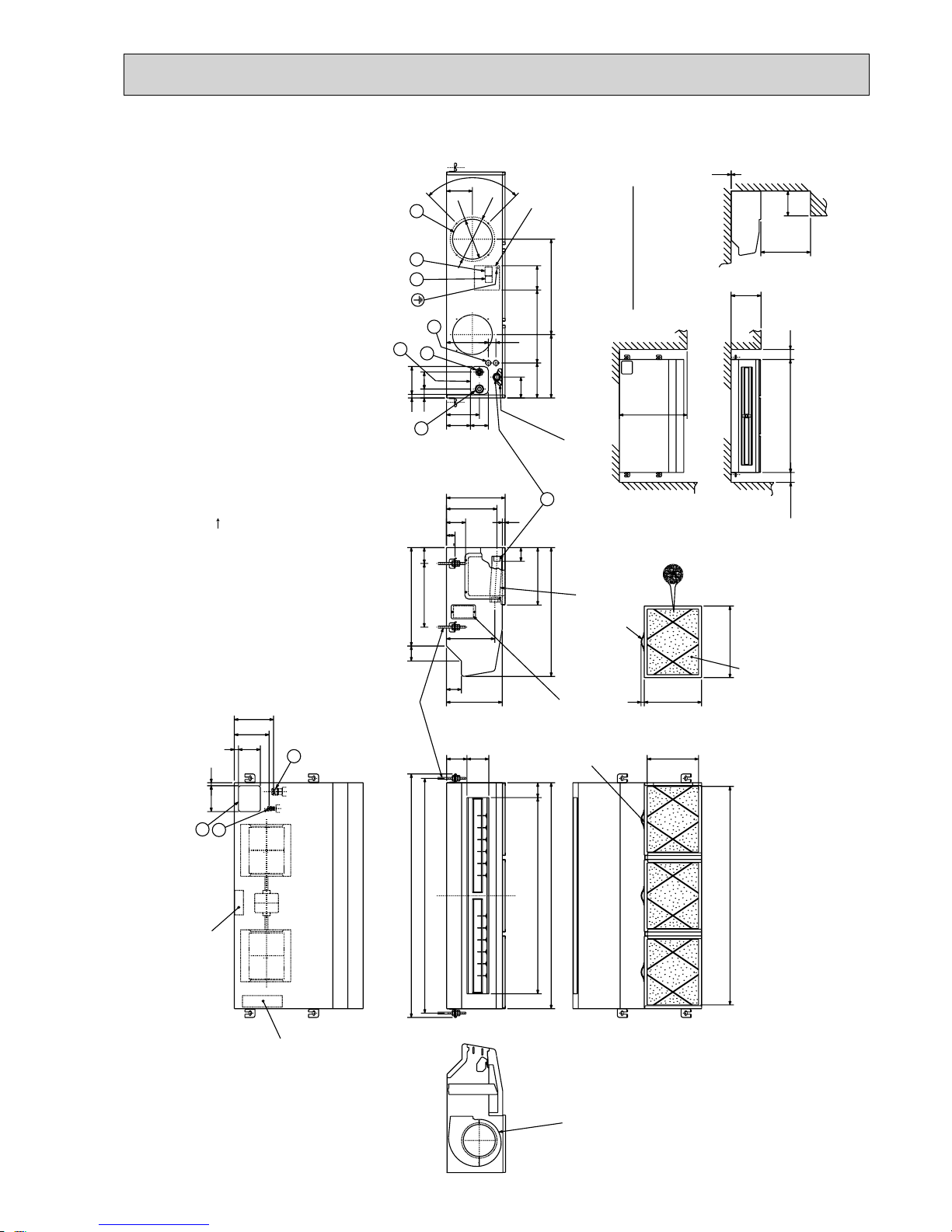
PCA-RP71HA
26
Unit : mmUnit : mm
Ceiling
Less than
Less than
Less than
or more
or more
or more
Refrigerant-pipe connection(gas pipe side/flared connection : 5/8 inch)
Knockout hole (duct for fresh air intake) : 2- : 200
· Optional parts:duct flange( : 200). model: PAC-SF28OF-E(1 pc.)
Flexible hose(accessory) Drainage pipe connection(26mm I.D.)
Terminal block(indoor/outdoor connecting line)
Terminal block(remote controller)
Refrigerant-pipe connection(liquid pipe side/flared connection : 3/8 inch)
Knockout hole for behind refrigerant-piping arrangement
Knockout hole for upper refrigerant-pipe arrangement
Knockout hole for wiring arrangement : 2- : 27
Allowing clearances
Rear wall
(Gap to ceiling)
NOTES.
1.Use M10 or W3/8 screw for anchor bolt.
Use the current nuts meeting the pipe size
of the outdoor unit.
model:PAC-SG38KF-E (12pcs.)
Filter element for the exchange
<Suspension bolt pitch>
(122)246
handle
16
<Flexible hose(accessory)>
Terminal block box
78
<Filter contour dimension>
Inspection port
(pipe sensor)
The half bottom of
FAN CASING
can be separated.
Adjustable part
288
360
<Air outlet>
<Suspension bolt pitch>
<Air outlet>
<Air intake>
<Air intake>
Filter (4-pieces)
Terminal block box
5
2
1
4
3
6
9
2
1
176
38 210
105
8545
165
:222
:200
440440298
130
90°
650
300
1001520100
Electrical box
500
250
2~3
<gas>
<liquid>
Suspension bolt
70
243
254
175
197
110
21
130 15
258
1482
110 102
1370 75
1608
320 801564
1520
90 120
14018
75
70~90
650
13
289
75
280
495
43
295
PCA-RP125HA
27
Unit : mm
125
240
Front side
Metal fixture
against overturning
controller
Rear side
Knockout hole
for branch duct
100
10
3838
50260
130130
766
1900
608
50
115
714 123
767
110
480
590
216
40
82730
2010
111
15
130
132
VIEW "A"
A
340
370
520
260
240
130 71
530
600
270
250
70
180
235
Knockout hole for
wiring :27
(Provided on both sides)
Knockout hole for refrigerant and drainage
90 60 oval (Provided on both sides)
Knockout hole for piping and wiring
(140 80 oval)
20
105
Terminal block for
indoor/outdoor
connection.
Electrical parts box
Liquid pipe :9.52(3/8 inch)
1. Service access allows for
insertion of screw driver.
2. Adjustable
Gas pipe :15.88(5/8 inch)
Drain pipe
Terminal block for
heater power supply
(Only PSH-P·GAH)
95
46122
47
Front side
Rear side
Knockout hole
for bottom fixing
Knockout hole
for under-piping
Knockout hole for
under-piping(120 70 oval)
277
160
20
218
175
90
55 143
100
95
40 66
186
100 or more 100 or more
2
5 or more
1
300 or more
Front 1,000 or more
10
PSA-RP71GA
 Loading...