

Mitsubishi PLA-RP_AA(2), PEAD-RP_EA(2), PEAD-RP_JA, PEAD-RP_GA, PKA-RP_GAL Technical Guide
...Page 1
SPLIT-TYPE, HEAT PUMP AIR CONDITIONERS
SPLIT-TYPE, AIR CONDITIONERS
TECHNICAL DATA BOOK
<Indoor unit>
[Model names]
PLA-RP·BA(2)
PLA-RP·AA
PLA-RP·AA2
PEAD-RP·JA(L)
PEAD-RP·EA(2)
PEAD-RP·GA
PKA-RP·GAL PKA-RP·HAL
PKA-RP·FAL(2) PKA-RP·KAL
PCA-RP·GA(2) PCA-RP·KA
R410A
October 2009
No. OCS07
REVISED EDITION-D
Revision:
• PLA-RP140BA2, PEAD-RP·JA(L),
PCA-RP·KA, PKA-RP·HAL/KAL
are added, and outdoor unit data
has been modified in REVISED
EDITION-D.
• Some descriptions have been
modified.
• Please void OCS07 REVISED
EDITION-C.
<Outdoor unit>
[Model names]
PCA-RP·HA
PSA-RP·GA
PMH-P·BA
PUH-P71/100VHA
PUH-P71/100/125/140YHA
PU-P71/100VHA
PU-P71/100/125/140YHA
CONTENTS
1. REFERENCE SERVICE MANUAL
2. SPECIFICATIONS
3. OUTLINES AND DIMENSIONS
4. WIRING DIAGRAM
5. REFRIGERANT SYSTEM DIAGRAM
6. PERFORMANCE CURVES
7. CORRECTION FACTORS
8. APPLICABLE EXTENSION PIPE FOR EACH MODEL
9. AIR FLOW DATA
10. NOISE CRITERION CURVES
11. OPTIONAL PARTS
.......................................................................
...................................................................
......................................................................
..........................................................................
.............................................
................................................
......................................
......................................................
........................................................
..........
.................................................
2
3
25
52
69
71
73
74
77
104
127
kW Model
Page 2
1
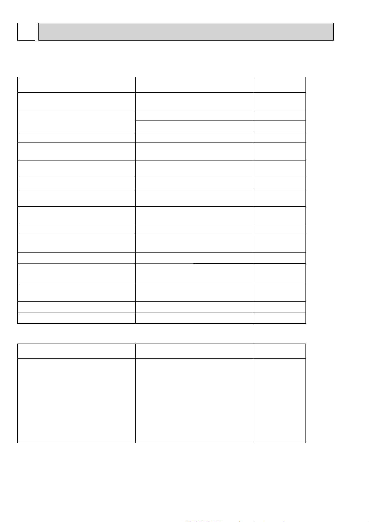
REFERENCE SERVICE MANUAL
For information on service, please refer to the service manual as follows.
1-1. Indoor Unit
Model name Service Ref. Service
PLA-RP35/50/60/71/100/125/140BA
PLA-RP140BA2
PLA-RP35/50/60/71/100/125/140BA#2.UK
PLA-RP140BA2.UK
Manual No.
OCH412
OCB412
PLA-RP35/50/60/71AA
PLA-RP100/125/140AA2 PLA-RP100/125/140AA2.UK OC357
PCA-RP50/60/71/100/125/140KA PCA-RP50/60/71/100/125/140KA
PCA-RP50/60/71/100/125/140GA
PCA-RP50GA2
PCA-RP71/125HA PCA-RP71/125HA#1 OC329
PKA-RP35/50HAL PKA-RP35/50HAL
PKA-RP60/71/100KAL PKA-RP60/71/100KAL.TH
PKA-RP35/50GAL PKA-RP35/50GAL OC330
PKA-RP60/71/100FAL
PKA-RP50FAL2
PSA-RP71/100/125/140GA PSA-RP71/100/125/140GA#1 OC332
PEAD-RP35/50/60/71/100/125/140JA(L) PEAD-RP35/50/60/71/100/125/140JA(L).UK
PEAD-RP50/60/71/125/140EA
PEAD-RP35/100EA2
PLA-RP35/50/60/71AA.UK OC335
PLA-RP35/50/60/71AA OC327
OCH454
OCB454
PCA-RP50/60/71/100/125/140GA
PCA-RP50GA2
PKA-RP60/71/100FAL
PKA-RP50FAL2
PEAD-RP50/60/71/125/140EA.UK
PEAD-RP35/100EA2.UK
OC328
OCH453
OCB453
OCH452
OCB452
OC331
HWE08130
BWE08240
HWE05210
PEAD-RP60/71/100GA PEAD-RP60/71/100GA.UK
PMH-P25/35/50BA PMH-P25/35/50BA OC333
HWE05060
1-2. Outdoor Unit
Model name Service Ref. Service
(1)
.UK
(1)
.UK
(1)
.UK
(1)
.UK
PUH-P71/100VHA
PUH-P71/100/125/140YHA
PU-P71/100VHA
PU-P71/100/125/140YHA
PUH-P71/100VHA
PUH-P71/100VHA#2.UK
PUH-P71/100VHAR3.UK
PUH-P71/100/125/140YHA
PUH-P71/100/125/140YHA#2.UK
PUH-P71/100/125/140YHAR3.UK
PU-P71/100VHA
PU-P71/100VHA#2.UK
PU-P71/100VHAR3.UK
PU-P71/100/125/140YHA
PU-P71/100/125/140YHA#2.UK
PU-P71/100/125/140YHAR3.UK
Manual No.
OC379
2
Page 3
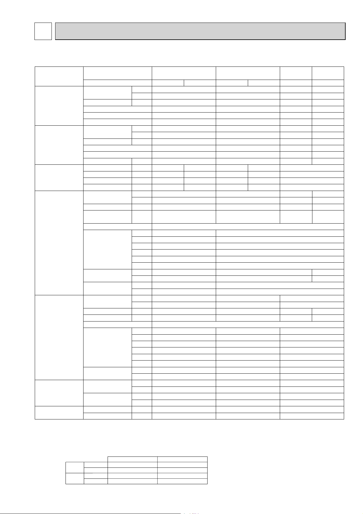
2
SPECIFICATIONS
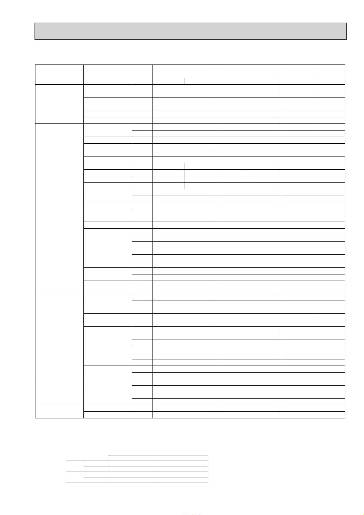
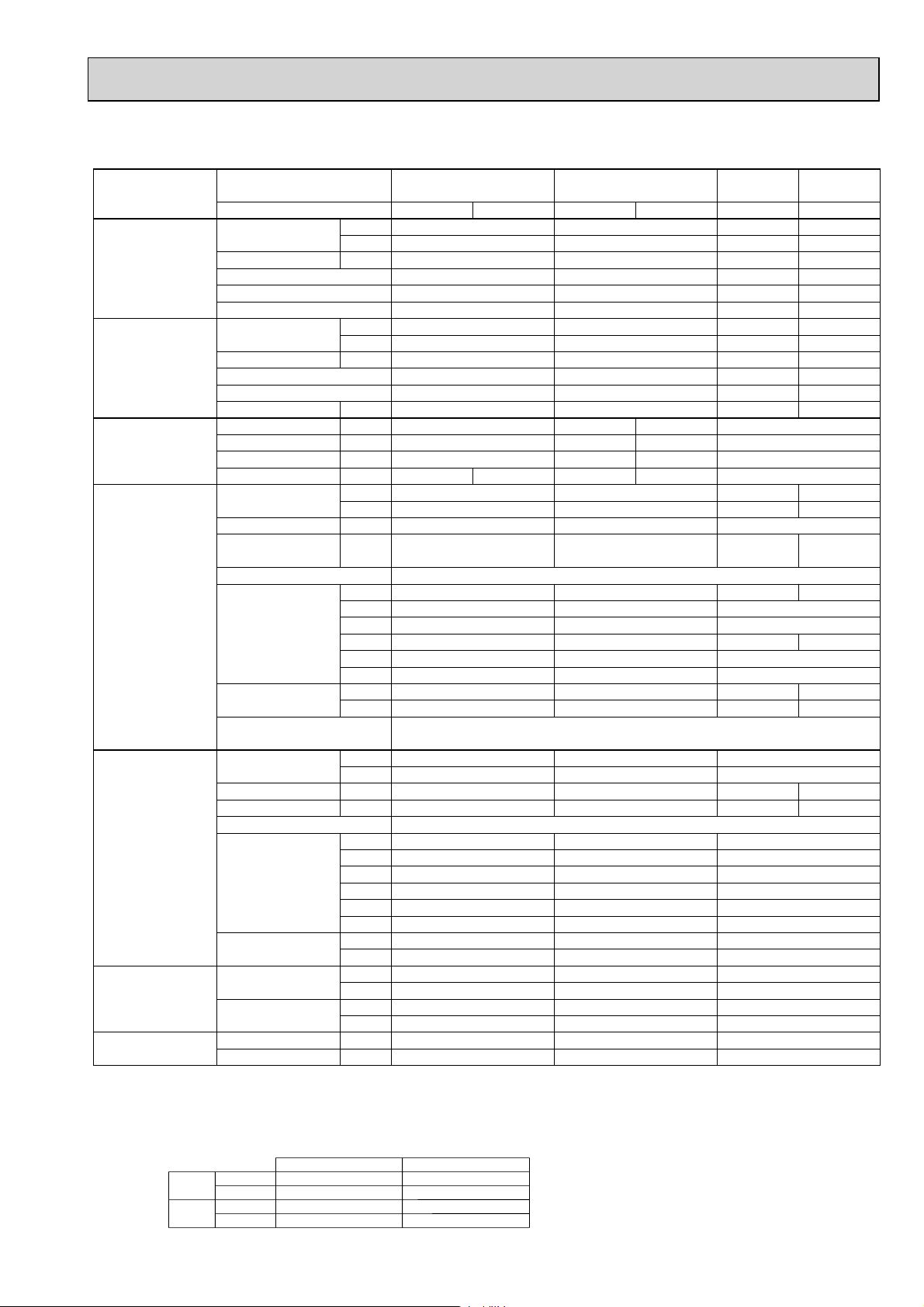
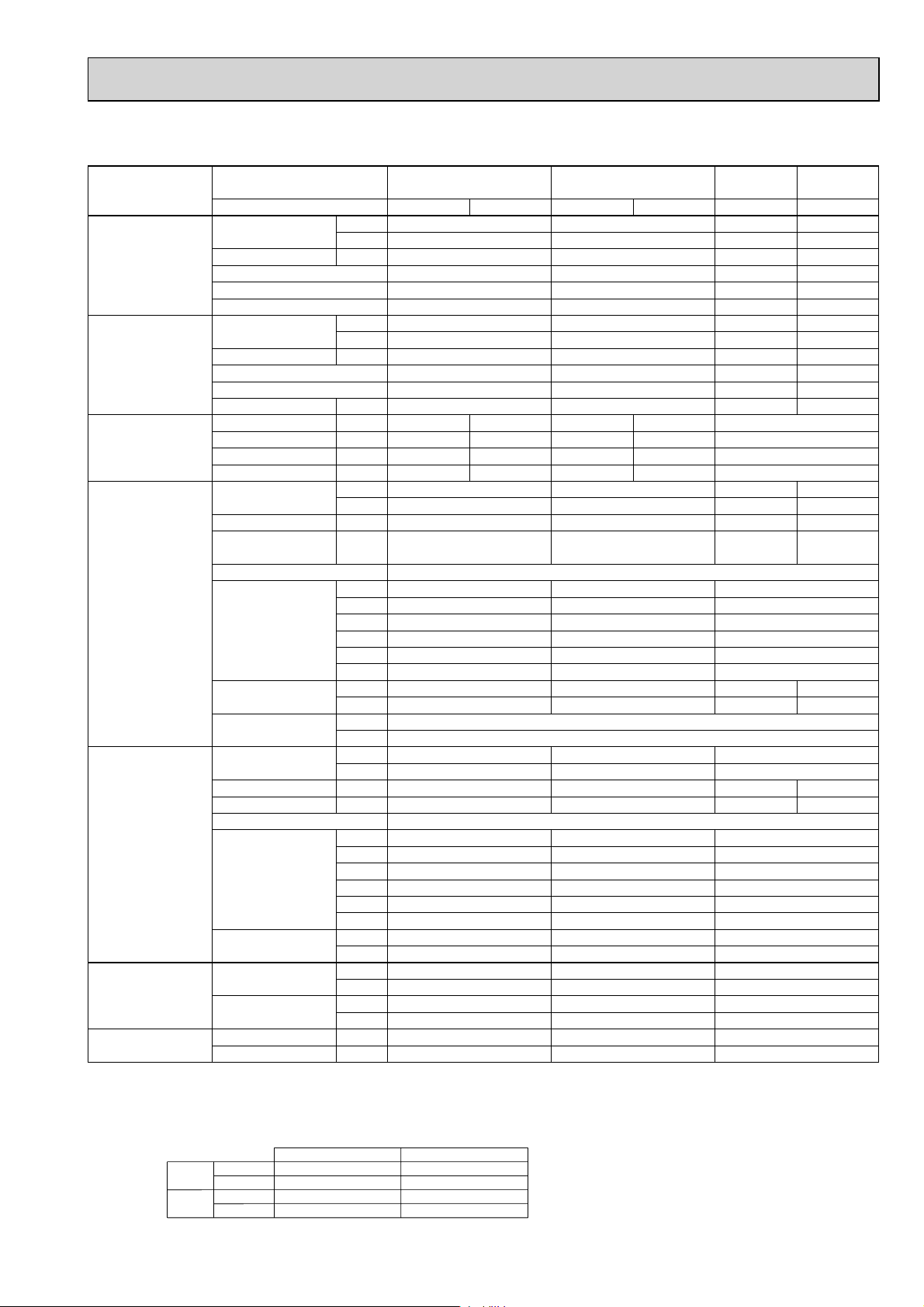
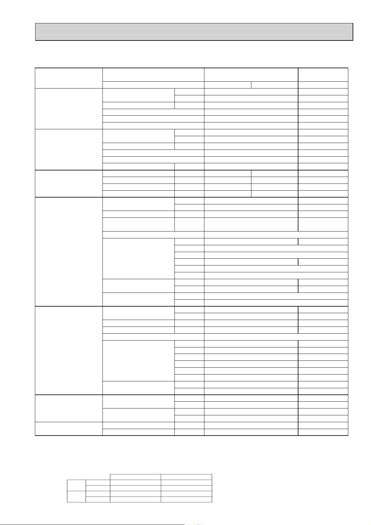
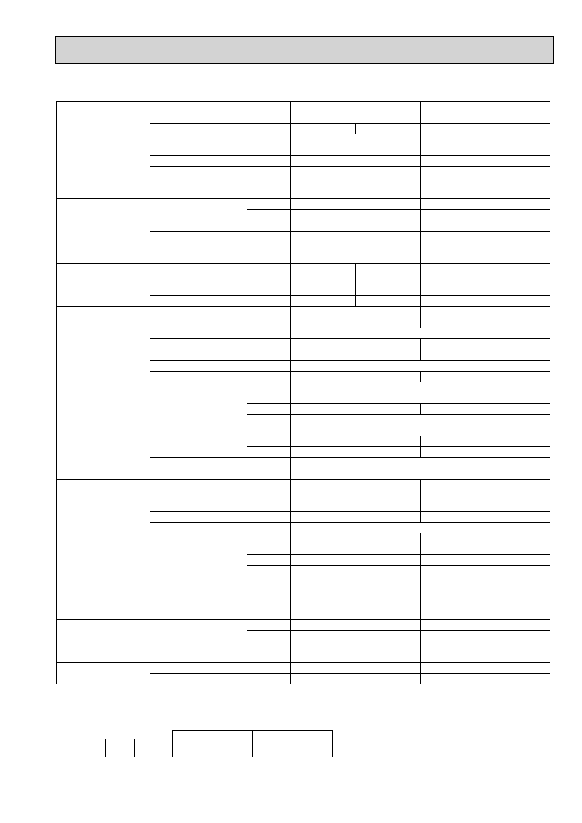
2-1. CEILING CASSETTE TYPE
Model name Indoor unit PLA-RP71BA PLA-RP100BA
Cooling
Heating
Power supply
Indoor unit
Outdoor unit
Refrigerant pipe size
Refrigerant pipe length
Outdoor unit PUH-P71VHA PUH-P71YHA
Capacity Btu/h 27,300 34,100 42,000 48,500
kW 8.0 10.0 12.3 14.2
Total input kW 2.83 3.53 4.36 5.41
EER 2.83 2.83 2.82 2.62
Energy label class
SHF 0.73 0.74 0.71 0.71
Capacity Btu/h 30,700 39,200 48,800 58,000
kW 9.0 11.5 14.3 17.0
Total input kW 2.82 3.40 4.23 5.35
COP 3.19 3.38 3.38 3.18
Energy label class — — — —
Booster heater kW — — — —
Phase : 1313 3
Cycle Hz50505050 50
Voltage V 230 400 230 400 400
Breaker size A 32 16 32 16 25
Air flow CMM 14-16-18-21 20-23-26-30 24-26-29-32
(
Low-Medium2-Medium1-High
External pressure Pa 0 0 0
Sound level dB(A
(
Low-Medium2-Medium1-High
External finish (Panel
Dimension W : mm 840(950
Unit(Panel
Weight kg
Unit(Panel
Field drain pipe O.D. mm 32 32
Air flow CMM 55 65 100
Sound level at cooling
Sound level at heating
External finish Ivory Munsell 3Y 7.8/1.1
Dimension W : mm 950 950 950
Weight kg 93 94 131
Gas side O.D. mm 15.88 15.88 15.88
Liquid side O.D. mm 9.52 9.52 9.52
Height difference
Length
)
CFM 495-565-635-740 710-810-920-1060
)
)
)
)
)
D : mm 840(950
H : mm 258(35
W : inch 33-1/16(37-3/8
D : inch 33-1/16(37-3/8
H : inch 10-3/16(1-3/8
lbs
inch 1-1/4 1-1/4
CFM 1,940 2,290 3,530
)
dB(A
)
dB(A
D : mm 330+30 330+30 330+30
H : mm 943 943 1350
W : inch 37-3/8 37-3/8 37-3/8
D : inch 13 + 1-3/16 13 + 1-3/16 13 + 1-3/16
H : inch 37-1/8 37-1/8 53-1/8
lbs 205 207 289
inch 5/8 5/8 5/8
inch 3/8 3/8 3/8
m Max. 50 Max. 50 Max. 50
m Max. 50 Max. 50 Max. 50
————
28-30-32-34 32-34-37-40 36-39-42-44
)
)
)
)
)
)
23 (6) 27 (6)
51 (13) 60 (13)
49 50 50 51
50 52 52 53
PUH-P100VHA PUH-P100YHA PUH-P125YHA PUH-P140YHA
White Munsell 6.4Y 8.9/0.4
25 (6)
55 (13)
PLA-RP125BA
22-25-28-31
780-880-990-1090
34-36-39-41
)
840(950
)
840(950
)
298(35
33-1/16(37-3/8
33-1/16(37-3/8
11-3/4 (1-3/8
PLA-RP140BA(2)
850-920-1020-1130
0
)
)
)
NOTE: 1. Rating conditions (ISO T1)
Cooling Indoor : D.B. 27 (80°F) W.B. 19 (66°F) Outdoor : D.B. 35 (95°F) W.B. 24 (75°F)
Heating Indoor : D.B. 20 (68°F) Outdoor : D.B. 7 (45°F) W.B. 6 (43°F)
Refrigerant piping length (one way) : 5m (16ft.)
2. Guaranteed operating range
Cooling
Heating
Upper limit
Lower limit
Upper limit
Lower limit
D.B. 35°C, W.B. 22.5°C
D.B. 19°C, W.B. 15°C D.B. -5 +
D.B. 28°C
D.B. 17°C D.B. -11, W.B. -12°C
Indoor Outdoor
D.B. 46
D.B. 21, W.B. 15°C
3
3. Guaranteed voltage
198~264V, 50Hz : Single phase
342~457V, 50Hz : 3 phase
4. Above data are based on the indicated voltage
Indoor unit Single phase 230V 50Hz
Outdoor unit
+ If optional Air protect guide installed. D.B.-15
Single phase 230V 50Hz
/ 3 phase 400V 50Hz
Page 4
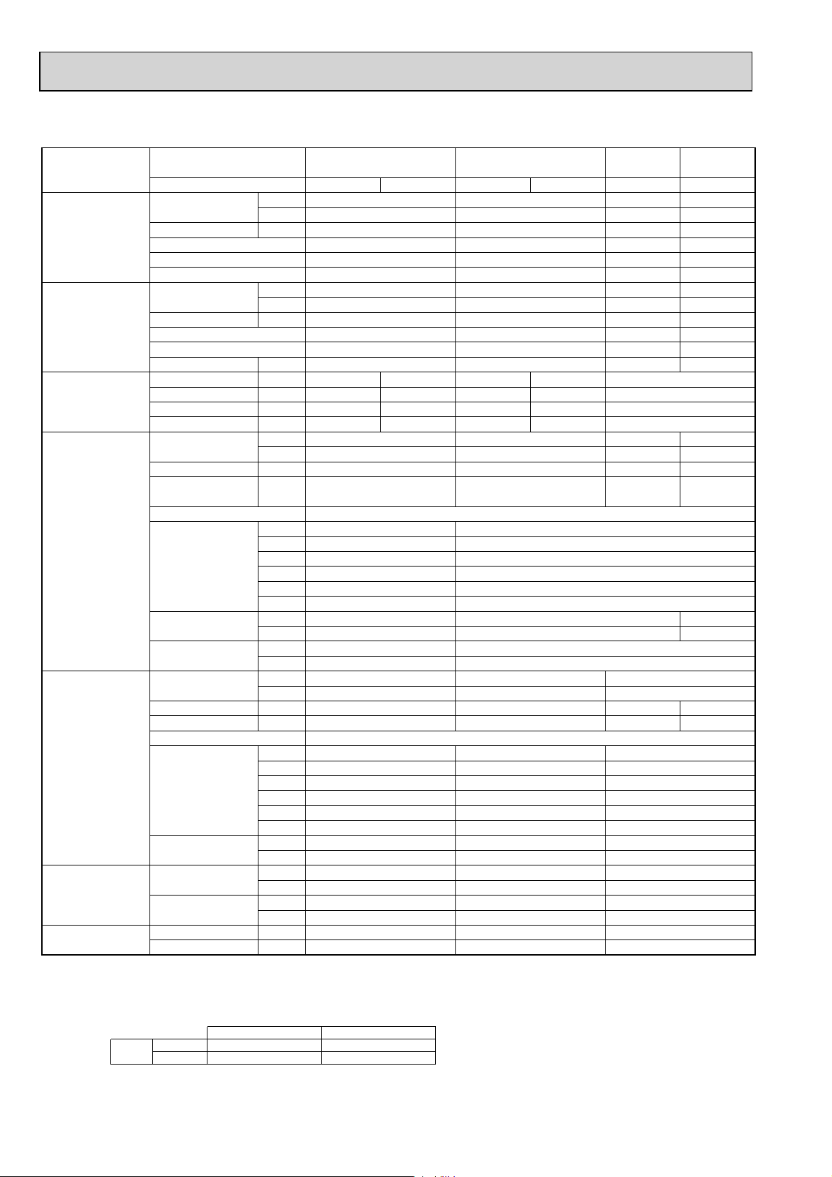
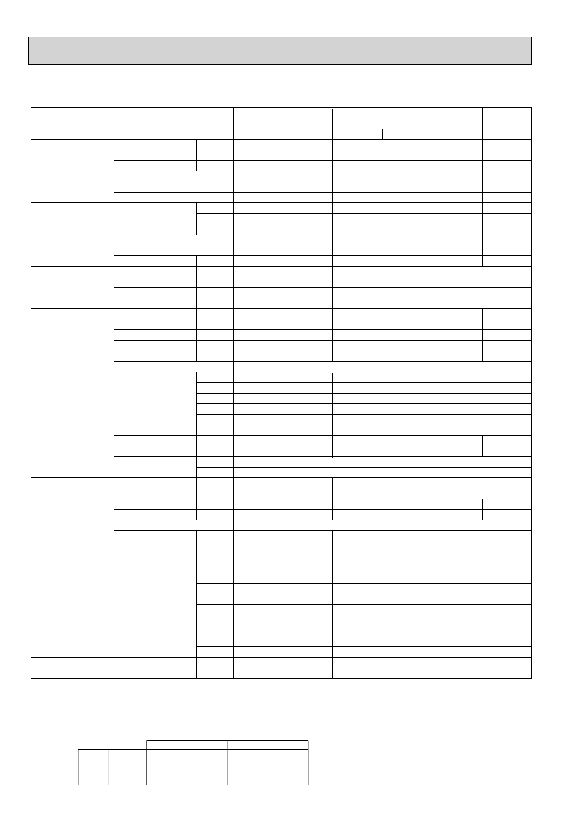
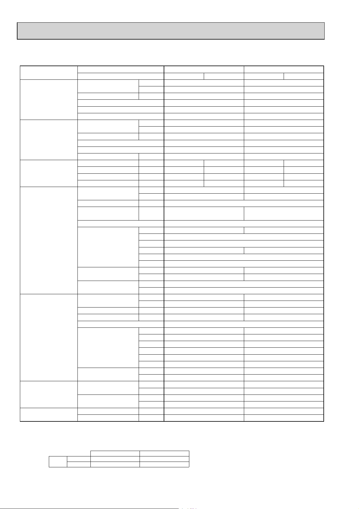
Model name Indoor unit PLA-RP71BA PLA-RP100BA
PLA-RP125BA
PLA-RP140BA(2)
Outdoor unit PU-P71VHA PU-P71YHA PU-P100VHA PU-P100YHA PU-P125YHA PU-P140YHA
Cooling Capacity Btu/h 27,300 34,100 42,000 48,500
kW 8.0 10.0 12.3 14.2
Total input kW 2.83 3.53 4.36 5.41
EER 2.83 2.83 2.82 2.62
Energy label class
————
SHF 0.73 0.74 0.71 0.71
Heating Capacity Btu/h — — — —
kW — — — —
Total input kW — — — —
COP — — — —
Energy label class
————
Booster heater kW — — — —
Power supply Phase : 1313 3
Cycle
Voltage
Hz 50 50 50 50 50
V 230 400 230 400 400
Breaker size A 32 16 32 16 25
Indoor unit Air flow CMM
(
Low-Medium2-Medium1-High
)
CFM
External pressure Pa
Sound level dB(A
(
Low-Medium2-Medium1-High
External finish (Panel
)
)
Dimension W : mm
Unit(Panel
)
D : mm
H : mm
W : inch
D : inch
H : inch
Weight kg
Unit(Panel
)
lbs
Field drain pipe O.D. mm
)
14-16-18-21 20-23-26-30 24-26-29-32
495-565-635-740 710-810-920-1060
00 0
28-30-32-34 32-34-37-40 36-39-42-44
22-25-28-31
780-880-990-1090
850-920-1020-1130
0
34-36-39-41
White Munsell 6.4Y 8.9/0.4
)
840(950
)
840(950
)
258(35
33-1/16(37-3/8
33-1/16(37-3/8
10-3/16(1-3/8
23 (6) 27 (6)
51 (13) 60 (13)
)
)
)
33-1/16(37-3/8
33-1/16(37-3/8
11-3/4 (1-3/8
25 (6)
55 (13)
840(950
840(950
298(35
)
)
)
)
)
)
32 32
inch 1-1/4 1-1/4
Outdoor unit
Air flow CMM 55 65 100
CFM 1,940 2,290 3,530
Sound level at cooling
Sound level at heating
dB(A
dB(A
)
)
49 50 50 51
————
External finish Ivory Munsell 3Y 7.8/1.1
Dimension W : mm 950 950 950
D : mm 330+30 330+30 330+30
H : mm 943 943 1350
W : inch 37-3/8 37-3/8 37-3/8
D : inch 13 + 1-3/16 13 + 1-3/16 13 + 1-3/16
H : inch 37-1/8 37-1/8 53-1/8
Weight kg 93 94 131
lbs 205 207 289
Refrigerant pipe size
Gas side O.D. mm 15.88 15.88 15.88
inch 5/8 5/8 5/8
Liquid side O.D. mm 9.52 9.52 9.52
inch 3/8 3/8 3/8
Refrigerant pipe length
Height difference
Length
m Max. 50 Max. 50 Max. 50
m Max. 50 Max. 50 Max. 50
NOTE: 1. Rating conditions (ISO T1)
Cooling Indoor : D.B. 27 (80°F) W.B. 19 (66°F) Outdoor : D.B. 35 (95°F) W.B. 24 (75°F)
Refrigerant piping length (one way) : 5m (16ft.)
2. Guaranteed operating range
Cooling
Upper limit
Lower limit
D.B. 35°C, W.B. 22.5°C
D.B. 19°C, W.B. 15°C D.B. -5 +
Indoor Outdoor
D.B. 46
3. Guaranteed voltage
198~264V, 50Hz : Single phase
342~457V, 50Hz : 3 phase
4. Above data are based on the indicated voltage
Indoor unit Single phase 230V 50Hz
Outdoor unit
+ If optional Air protect guide installed. D.B.-15
Single phase 230V 50Hz
/ 3 phase 400V 50Hz
44
Page 5
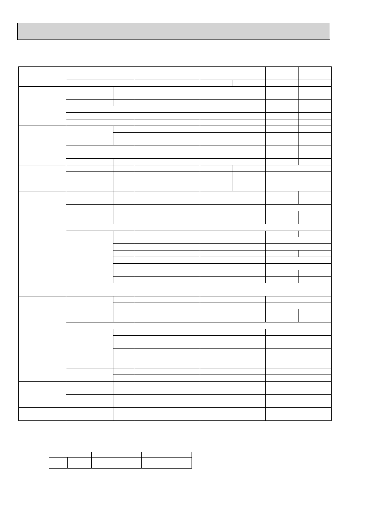
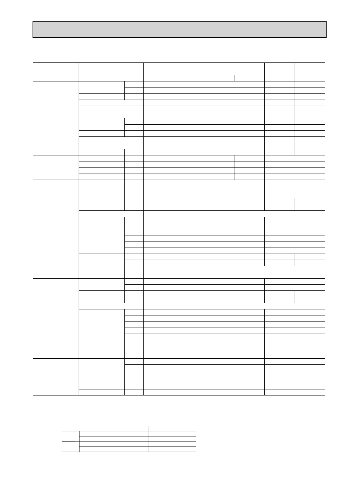
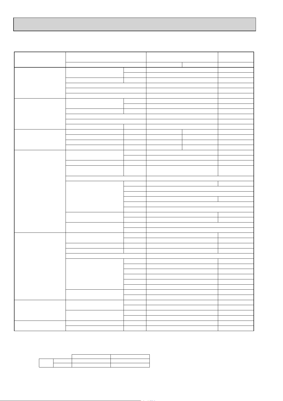
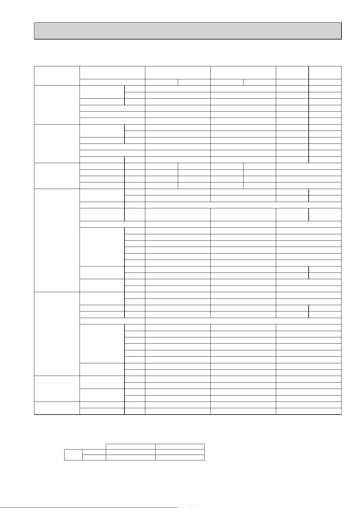
Model name Indoor unit PLA-RP71AA PLA-RP100AA2
PLA-RP125AA2 PLA-RP140AA2
Outdoor unit PUH-P71VHA PUH-P71YHA
PUH-P100VHA PUH-P100YHA PUH-P125YHA PUH-P140YHA
Cooling Capacity Btu/h 27,300 34,100 42,000 48,500
kW 8.0 10.0 12.3 14.2
Total input kW 2.83 3.53 4.36 5.41
EER 2.83 2.83 2.82 2.62
Energy label class C C C D
SHF 0.74 0.78 0.74 0.71
Heating Capacity Btu/h 30,700 [37,300] 39,200 48,800 58,000
kW 9.0 [10.93] 11.5 14.3 17.0
Total input kW 2.82 [4.75] 3.40 4.23 5.35
COP 3.19 3.38 3.38 3.18
Energy label class D C C D
Booster heater kW [2.1] — — —
Power supply Phase : 1313 3
Cycle Hz50505050 50
Voltage V 230 400 230 400 400
Breaker size A 32 16 32 16 25
Indoor unit Air flow CMM 15-16-18-20 19-21-23-27 24-25-27-30
(
Low-Medium2-Medium1-High
)
CFM 530-565-635-705 670-740-810-950 850-880-950-1060
External pressure Pa 0 0 0
Sound level dB(A
(
Low-Medium2-Medium1-High
External finish (Panel
)
Dimension W : mm 840(950
Unit(Panel
)
Weight kg 24 [26] (5
Unit(Panel
)
)
28-30-32-34 33-36-39-41 37-40-43-45
)
D : mm 840(950
H : mm 258(30
W : inch 33-1/16(37-3/8
D : inch 33-1/16(37-3/8
H : inch 10-3/16(1-3/16
lbs 53 [57] (11
)
)
)
)
)
)
33-1/16(37-3/8
33-1/16(37-3/8
11-3/4 (1-3/16
)
)
840(950
840(950
298(30
32(5
71(11
)
)
)
)
)
)
)
)
White Munsell 0.70Y 8.59/0.97
Field drain pipe O.D. mm 32 32
inch 1-1/4 1-1/4
Outdoor unit Air flow CMM 55 65 100
CFM 1,940 2,290 3,530
Sound level at cooling dB(A
Sound level at heating dB(A
)
)
49 50 50 51
50 52 52 53
External finish Ivory Munsell 3Y 7.8/1.1
Dimension W : mm 950 950 950
D : mm 330+30 330+30 330+30
H : mm 943 943 1350
W : inch 37-3/8 37-3/8 37-3/8
D : inch 13 + 1-3/16 13 + 1-3/16 13 + 1-3/16
H : inch 37-1/8 37-1/8 53-1/8
Weight kg 93 94 131
lbs 205 207 289
Refrigerant pipe size Gas side O.D. mm 15.88 15.88 15.88
inch 5/8 5/8 5/8
Liquid side O.D. mm 9.52 9.52 9.52
inch 3/8 3/8 3/8
Refrigerant pipe length Height difference m Max. 50 Max. 50 Max. 50
Length m Max. 50 Max. 50 Max. 50
NOTE: 1. Rating conditions (ISO T1)
Cooling Indoor : D.B. 27 (80°F) W.B. 19 (66°F) Outdoor : D.B. 35 (95°F) W.B. 24 (75°F)
Heating Indoor : D.B. 20 (68°F) Outdoor : D.B. 7 (45°F) W.B. 6 (43°F)
Refrigerant piping length (one way) : 5m (16ft.)
2. Guaranteed operating range
Cooling
Heating
Upper limit
Lower limit
Upper limit
Lower limit
D.B. 35°C, W.B. 22.5°C
D.B. 19°C, W.B. 15°C D.B. -5 +
D.B. 28°C
D.B. 17°C D.B. -11, W.B. -12°C
Indoor Outdoor
D.B. 46
D.B. 21, W.B. 15°C
55
3. Guaranteed voltage
198~264V, 50Hz : Single phase
342~457V, 50Hz : 3 phase
4. Above data are based on the indicated voltage
Indoor unit Single phase 230V 50Hz
Outdoor unit
+ If optional Air protect guide installed. D.B.-15
Single phase 230V 50Hz
/ 3 phase 400V 50Hz
Page 6
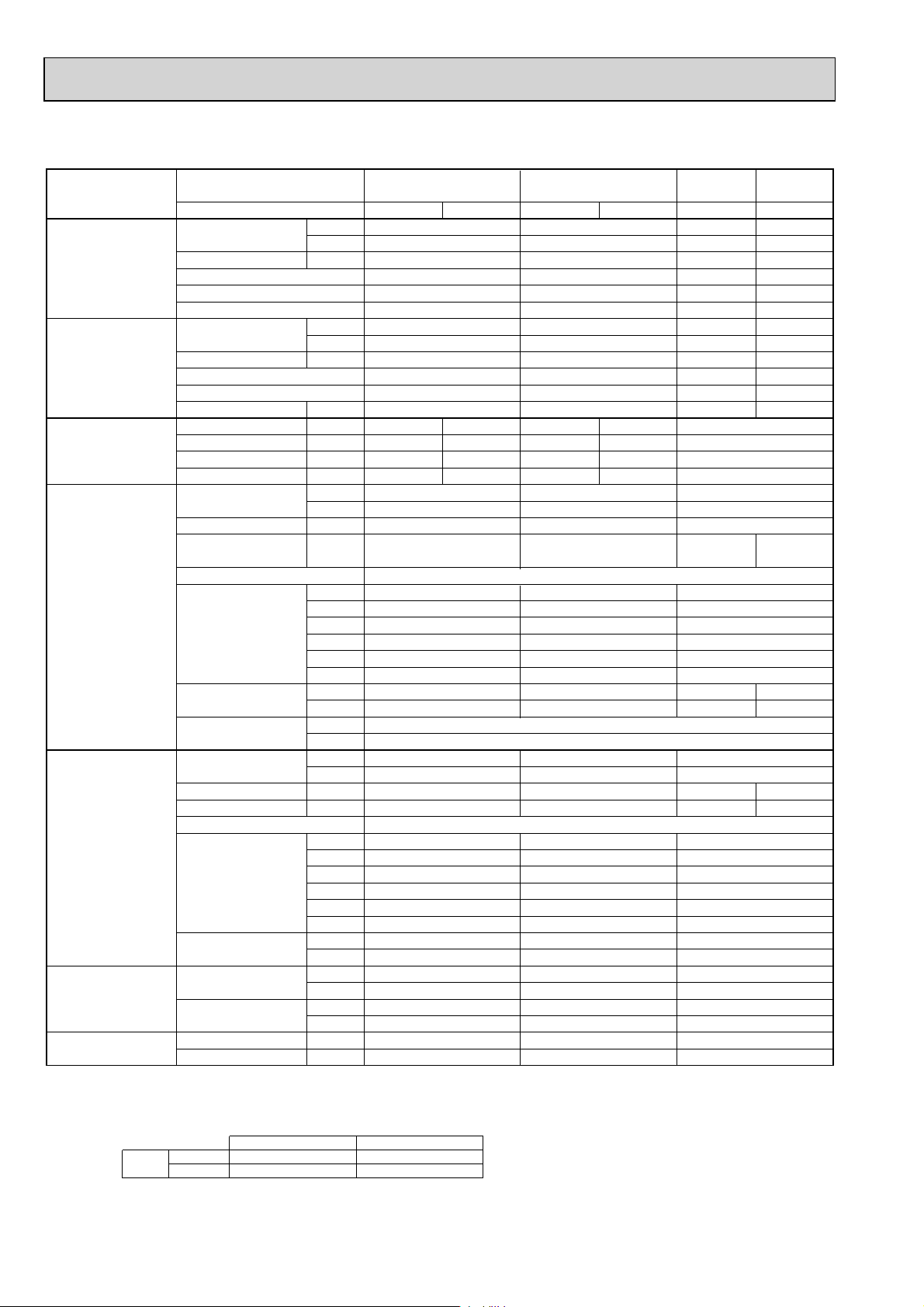
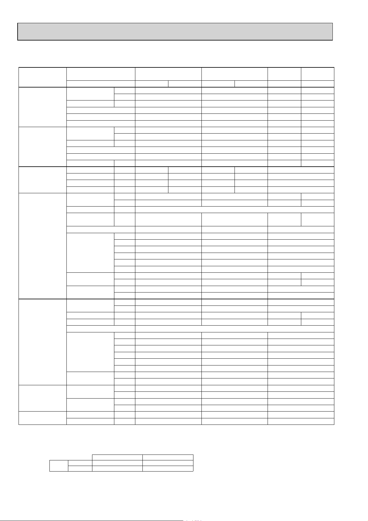
Model name Indoor unit PLA-RP71AA PLA-RP100AA2
PLA-RP125AA2 PLA-RP140AA2
Outdoor unit PU-P71VHA PU-P71YHA PU-P100VHA PU-P100YHA PU-P125YHA PU-P140YHA
Cooling Capacity Btu/h 27,300 34,100 42,000 48,500
kW 8.0 10.0 12.3 14.2
Total input kW 2.83 3.53 4.36 5.41
EER 2.83 2.83 2.82 2.62
Energy label class C C C D
SHF 0.74 0.78 0.74 0.71
Heating Capacity Btu/h — — — —
kW — — — —
Total input kW — — — —
COP — — — —
Energy label class — — — —
Booster heater kW — — — —
Power supply Phase : 1313 3
Cycle Hz50505050 50
Voltage V 230 400 230 400 400
Breaker size A 32 16 32 16 25
Indoor unit Air flow CMM 15-16-18-20 19-21-23-27 24-25-27-30
(
Low-Medium2-Medium1-High
)
CFM 530-565-635-705 670-740-810-950 850-880-950-1060
External pressure Pa 0 0 0
Sound level dB(A
(
Low-Medium2-Medium1-High
External finish (Panel
)
Dimension W : mm 840(950
Unit(Panel
)
Weight kg 24(5
Unit(Panel
)
)
28-30-32-34 33-36-39-41 37-40-43-45
)
D : mm 840(950
H : mm 258(30
W : inch 33-1/16(37-3/8
D : inch 33-1/16(37-3/8
H : inch 10-3/16(1-3/16
lbs 53(11
)
)
)
)
)
)
33-1/16(37-3/8
33-1/16(37-3/8
11-3/4 (1-3/16
)
)
840(950
840(950
298(30
32(5
71(11
)
)
)
)
)
)
)
)
White Munsell 0.70Y 8.59/0.97
Field drain pipe O.D. mm 32 32
inch 1-1/4 1-1/4
Outdoor unit Air flow CMM 55 65 100
CFM 1,940 2,290 3,530
Sound level at cooling dB(A
Sound level at heating dB(A
)
)
49 50 50 51
————
External finish Ivory Munsell 3Y 7.8/1.1
Dimension W : mm 950 950 950
D : mm 330+30 330+30 330+30
H : mm 943 943 1350
W : inch 37-3/8 37-3/8 37-3/8
D : inch 13 + 1-3/16 13 + 1-3/16 13 + 1-3/16
H : inch 37-1/8 37-1/8 53-1/8
Weight kg 93 94 131
lbs 205 207 289
Refrigerant pipe size Gas side O.D. mm 15.88 15.88 15.88
inch 5/8 5/8 5/8
Liquid side O.D. mm 9.52 9.52 9.52
inch 3/8 3/8 3/8
Refrigerant pipe length
Height difference m Max. 50 Max. 50 Max. 50
Length m Max. 50 Max. 50 Max. 50
NOTE: 1. Rating conditions (ISO T1)
Cooling Indoor : D.B. 27 (80°F) W.B. 19 (66°F) Outdoor : D.B. 35 (95°F) W.B. 24 (75°F)
Refrigerant piping length (one way) : 5m (16ft.)
2. Guaranteed operating range
Cooling
Upper limit
Lower limit
D.B. 35°C, W.B. 22.5°C
D.B. 19°C, W.B. 15°C D.B. -5 +
Indoor Outdoor
D.B. 46
3. Guaranteed voltage
198~264V, 50Hz : Single phase
342~457V, 50Hz : 3 phase
4. Above data are based on the indicated voltage
Indoor unit Single phase 230V 50Hz
Outdoor unit
+ If optional Air protect guide installed. D.B.-15
Single phase 230V 50Hz
/ 3 phase 400V 50Hz
6
Page 7
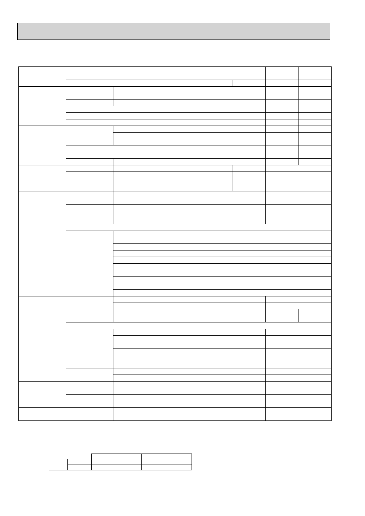
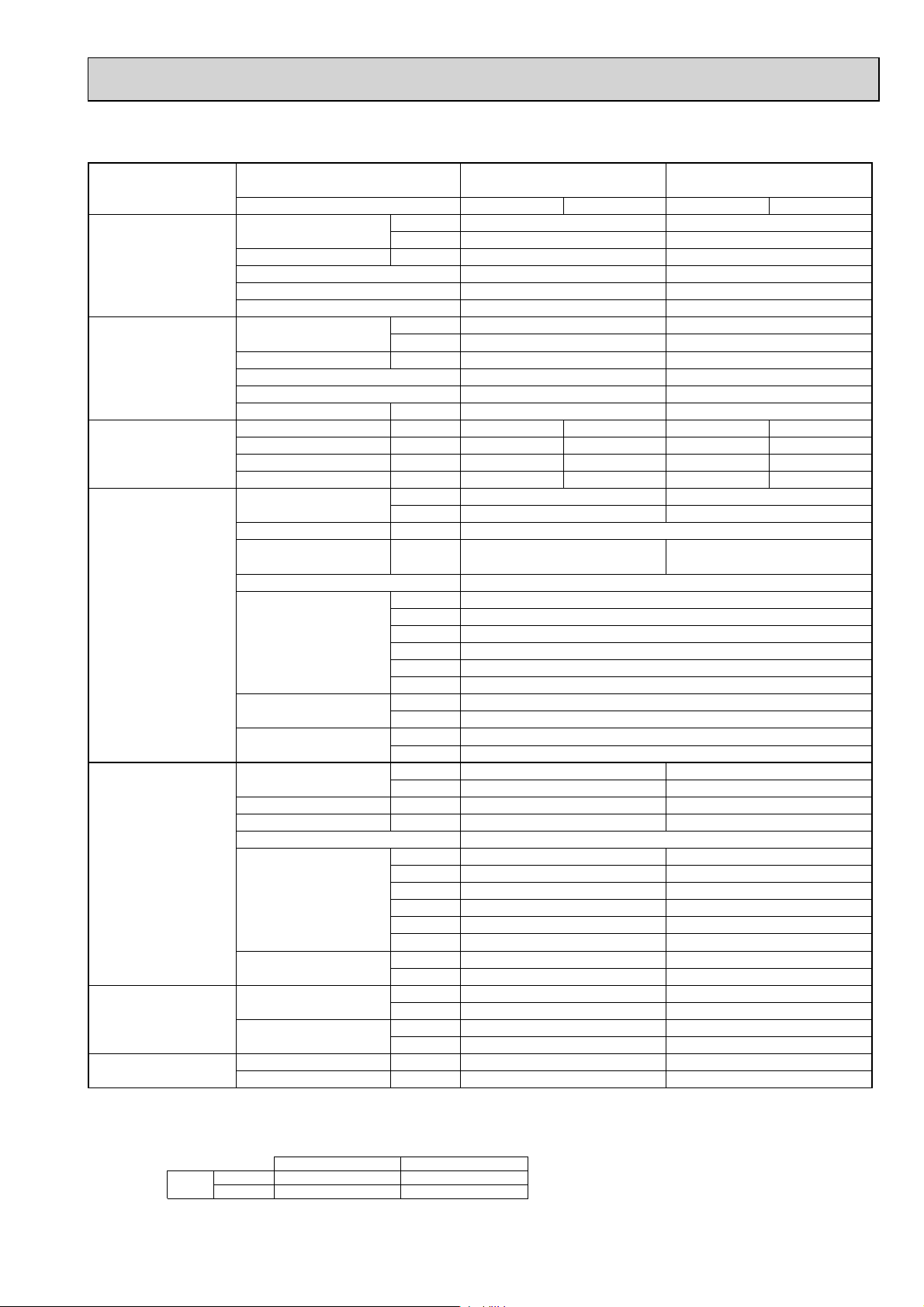
2-2. CEILING-CONCEALED TYPE
Model name Indoor unit PEAD-RP71JA(L) PEAD-RP100JA(L)
Outdoor unit
PUH-P71VHA PUH-P71YHA PUH-P100VHA PUH-P100YHA PUH-P125YHA PUH-P140YHA
PEAD-RP125JA(L) PEAD-RP140JA(L)
Cooling Capacity Btu/h 27,000 34,100 42,000 48,500
kW 7.9 10.0 12.3 14.2
Total input kW 2.97 (2.95) 3.69 (3.67) 4.41 (4.39) 5.63 (5.61)
EER 2.66 (2.68) 2.71 (2.72) 2.79 (2.80) 2.52 (2.53)
Energy label class — — — —
SHF 0.83 0.82 0.84 0.83
Heating Capacity Btu/h 30,700 39,200 48,800 57,000
kW 9.0 11.5 14.3 16.7
Total input kW 3.11 3.42 4.32 5.28
COP 2.89 3.36 3.31 3.16
Energy label class — — — —
Booster heater kW — — — —
Power supply Phase : 1133
Cycle Hz 50 50 50 50
Voltage V 230 230 400 400
Breaker size A 32 16 32 16 25
Indoor unit Air flow CMM 17.5 - 21 - 25 24 - 29 - 34 29.5 - 35.5 - 42 32 - 39 - 46
(
Low-Middle-High
)
CFM 618 - 742 - 883 847 - 1024 - 1201
1042-1253-1483
1130-1377-1624
External pressure Pa 35/50/70/100/150 35/50/70/100/150 35/50/70/100/150
Sound level dB(A
(
Low-Middle-High
)
)
25 - 29 - 33 29 - 34 - 38 33 - 36 - 40 34 - 38 - 43
External finish Galvanized sheets
Dimension W : mm 1100 1400 1400 1600
D : mm 732 732 732
H : mm 250 250 250
W : inch 43 - 5/16 55 - 1/8 55 - 1/8 63
D : inch 28 - 7/8 28 - 7/8 28 - 7/8
H : inch 9 - 7/8 9 - 7/8 9 - 7/8
Weight kg 33 (32) 41 (40) 43 (42) 47 (46)
lbs 73 (71) 91 (89) 95 (93) 104 (102)
Field drain pipe O.D.
mm
inch
32
1 - 1/4
Outdoor unit Air flow CMM 55 65 100
CFM 1,940 2,290 3,530
Sound level at cooling dB(A
Sound level at heating dB(A
)
)
49 50 50 51
50 52 52 53
External finish Ivory Munsell 3Y 7.8/1.1
Dimension W : mm 950 950 950
D : mm 330+30 330+30 330+30
H : mm 943 943 1350
W : inch 37-3/8 37-3/8 37-3/8
D : inch 13 + 1-3/16 13 + 1-3/16 13 + 1-3/16
H : inch 37-1/8 37-1/8 53-1/8
Weight kg 93 94 131
lbs 205 207 289
Refrigerant pipe size Gas side O.D. mm 15.88 15.88 15.88
inch 5/8 5/8 5/8
Liquid side O.D. mm 9.52 9.52 9.52
inch 3/8 3/8 3/8
Refrigerant pipe length Height difference m Max. 50 Max. 50 Max. 50
Length m Max. 50 Max. 50 Max. 50
NOTE: 1. Rating conditions (ISO T1)
Cooling Indoor : D.B. 27 (80°F) W.B. 19 (66°F) Outdoor : D.B. 35 (95°F) W.B. 24 (75°F)
Heating Indoor : D.B. 20 (68°F) Outdoor : D.B. 7 (45°F) W.B. 6 (43°F)
Refrigerant piping length (one way) : 5m (16ft.)
2. Guaranteed operating range
Cooling
Heating
Upper limit
Lower limit
Upper limit
Lower limit
D.B. 35°C, W.B. 22.5°C
D.B. 19°C, W.B. 15°C D.B. -5 +
D.B. 28°C
D.B. 17°C D.B. -11, W.B. -12°C
Indoor Outdoor
D.B. 46
D.B. 21, W.B. 15°C
7
3. Guaranteed voltage
198~264V, 50Hz : Single phase
342~457V, 50Hz : 3 phase
4. Above data are based on the indicated voltage
Indoor unit Single phase 230V 50Hz
Outdoor unit
+ If optional Air protect guide installed. D.B.-15
Single phase 230V 50Hz
/ 3 phase 400V 50Hz
Page 8
Model name Indoor unit PEAD-RP71JA(L) PEAD-RP100JA(L)
PEAD-RP125JA(L) PEAD-RP140JA(L)
Outdoor unit PU-P71VHA PU-P71YHA PU-P100VHA PU-P100YHA PU-P125YHA PU-P140YHA
Cooling Capacity Btu/h 27,000 34,100 42,000 48,500
kW 7.9 10.0 12.3 14.2
Total input kW 2.97 (2.95) 3.69 (3.67) 4.41 (4.39) 5.63 (5.61)
EER 2.66 (2.68) 2.71 (2.72) 2.79 (2.80) 2.52 (2.53)
Energy label class — — — —
SHF 0.83 0.82 0.84 0.83
Heating Capacity Btu/h — — — —
kW — — — —
Total input kW — — — —
COP — — — —
Energy label class — — — —
Booster heater kW — — — —
Power supply Phase : 1133
Cycle Hz 50 50 50 50
Voltage V 230 230 400 400
Breaker size A 32 16 32 16 25
Indoor unit Air flow CMM 17.5 - 21 - 25 24 - 29 - 34 29.5 - 35.5 - 42 32 - 39 - 46
(
Low-Middle-High
)
CFM 618 - 742 - 883 847 - 1024 - 1201
1042-1253-1483 1130-1377-1624
External pressure Pa 35/50/70/100/150 35/50/70/100/150 35/50/70/100/150
Sound level dB(A
(
Low-Middle-High
)
)
26 - 30 - 34 29 - 34 - 38 33 - 36 - 40 34 - 38 - 43
External finish Galvanized sheets
Dimension W : mm 1100 1400 1400 1600
D : mm 732 732 732
H : mm 250 250 250
W : inch 43 - 5/16 55 - 1/8 55 - 1/8 63
D : inch 28 - 7/8 28 - 7/8 28 - 7/8
H : inch 9 - 7/8 9 - 7/8 9 - 7/8
Weight kg 33 (32) 41 (40) 43 (42) 47 (46)
lbs 73 (71) 91 (89) 95 (93) 104 (102)
Field drain pipe O.D. 32
mm
inch
1 - 1/4
Outdoor unit Air flow CMM 55 65 100
CFM 1,940 2,290 3,530
Sound level at cooling dB(A
Sound level at heating dB(A
)
)
49 50 50 51
————
External finish Ivory Munsell 3Y 7.8/1.1
Dimension W : mm 950 950 950
D : mm 330+30 330+30 330+30
H : mm 943 943 1350
W : inch 37-3/8 37-3/8 37-3/8
D : inch 13 + 1-3/16 13 + 1-3/16 13 + 1-3/16
H : inch 37-1/8 37-1/8 53-1/8
Weight kg 93 94 131
lbs 205 207 289
Refrigerant pipe size Gas side O.D. mm 15.88 15.88 15.88
inch 5/8 5/8 5/8
Liquid side O.D. mm 9.52 9.52 9.52
inch 3/8 3/8 3/8
Refrigerant pipe length Height difference m Max. 50 Max. 50 Max. 50
Length m Max. 50 Max. 50 Max. 50
NOTE: 1. Rating conditions (ISO T1)
Cooling Indoor : D.B. 27 (80°F) W.B. 19 (66°F) Outdoor : D.B. 35 (95°F) W.B. 24 (75°F)
Heating Indoor : D.B. 20 (68°F) Outdoor : D.B. 7 (45°F) W.B. 6 (43°F)
Refrigerant piping length (one way) : 5m (16ft.)
2. Guaranteed operating range
Cooling
Heating
Upper limit
Lower limit
Upper limit
Lower limit
D.B. 35°C, W.B. 22.5°C
D.B. 19°C, W.B. 15°C D.B. -5 +
D.B. 28°C
D.B. 17°C D.B. -11, W.B. -12°C
Indoor Outdoor
D.B. 46
D.B. 21, W.B. 15°C
3. Guaranteed voltage
198~264V, 50Hz : Single phase
342~457V, 50Hz : 3 phase
4. Above data are based on the indicated voltage
Indoor unit Single phase 230V 50Hz
Outdoor unit
+ If optional Air protect guide installed. D.B.-15
Single phase 230V 50Hz
/ 3 phase 400V 50Hz
8
Page 9
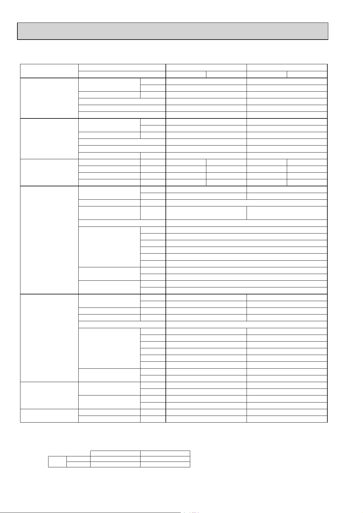
Model name Indoor unit PEAD-RP71EA PEAD-RP100EA2
PEAD-RP125EA PEAD-RP140EA
Outdoor unit
PUH-P71VHA PUH-P71YHA PUH-P100VHA PUH-P100YHA PUH-P125YHA PUH-P140YHA
Cooling Capacity Btu/h 27,000 34,100 42,000 48,500
kW 7.9 10.0 12.3 14.2
Total input kW 2.97 3.69 4.41 5.63
EER 2.66 2.71 2.79 2.52
Energy label class D D D E
SHF 0.83 0.86 0.82 0.83
Heating Capacity Btu/h 30,700 [37,300] 39,200 [46,800] 48,800 [58,200] 57,000 [66,400]
kW 9.0 [10.93] 11.5 [13.71] 14.3 [17.06] 16.7 [19.46]
Total input kW 3.11 [5.04] 3.42 [5.63] 4.32 [7.08] 5.28 [8.04]
COP 2.89 3.36 3.31 3.16
Energy label class D C C D
Booster heater kW [2.1] [2.4] [3.0] [3.0]
Power supply Phase : 1133
Cycle Hz 50 50 50 50
Voltage V 230 230 400 400
Breaker size A 32 16 32 16 25
Indoor unit Air flow CMM 20-25 33.5-42 33.5-42 36.5-46
(
Low-High
External pressure Pa 70(130
Sound level dB(A
(
Low-High
)
)(
CFM 706-883 1183-1483 1183-1483 1288-1624
)
)
37-41 44-50 44-50 46-51
130Pa : 40-45
)(
70(130
130Pa : 46-52
)
)(
130Pa : 46-52)(130Pa : 47-53
70(130
)
)
External finish Galvanized sheets
Dimension W : mm 1175 1415 1415 1715
D : mm 740 740 740
H : mm 325 325 325
W : inch 46-1/8 55-11/16 55-11/16 67-1/2
D : inch 29-1/8 29-1/8 29-1/8
H : inch 12-13/16 12-13/16 12-13/16
Weight kg 44 [46] 65 [68] 65 [68] 70 [73]
lbs 97 [101] 143 [150] 143 [150] 154 [161]
Unit drain pipe R1(External thread
)
Outdoor unit Air flow CMM 55 65 100
CFM 1,940 2,290 3,530
Sound level at cooling dB(A
Sound level at heating dB(A
)
)
49 50 50 51
50 52 52 53
External finish Ivory Munsell 3Y 7.8/1.1
Dimension W : mm 950 950 950
D : mm 330+30 330+30 330+30
H : mm 943 943 1350
W : inch 37-3/8 37-3/8 37-3/8
D : inch 13 + 1-3/16 13 + 1-3/16 13 + 1-3/16
H : inch 37-1/8 37-1/8 53-1/8
Weight kg 93 94 131
lbs 205 207 289
Refrigerant pipe size Gas side O.D. mm 15.88 15.88 15.88
inch 5/8 5/8 5/8
Liquid side O.D. mm 9.52 9.52 9.52
inch 3/8 3/8 3/8
Refrigerant pipe length Height difference m Max. 50 Max. 50 Max. 50
Length m Max. 50 Max. 50 Max. 50
NOTE: 1. Rating conditions (ISO T1)
Cooling Indoor : D.B. 27 (80°F) W.B. 19 (66°F) Outdoor : D.B. 35 (95°F) W.B. 24 (75°F)
Heating Indoor : D.B. 20 (68°F) Outdoor : D.B. 7 (45°F) W.B. 6 (43°F)
Refrigerant piping length (one way) : 5m (16ft.)
2. Guaranteed operating range
Cooling
Heating
Upper limit
Lower limit
Upper limit
Lower limit
D.B. 35°C, W.B. 22.5°C
D.B. 19°C, W.B. 15°C D.B. -5 +
D.B. 28°C
D.B. 17°C D.B. -11, W.B. -12°C
Indoor Outdoor
D.B. 46
D.B. 21, W.B. 15°C
3. Guaranteed voltage
198~264V, 50Hz : Single phase
342~457V, 50Hz : 3 phase
4. Above data are based on the indicated voltage
Indoor unit Single phase 230V 50Hz
Outdoor unit
+ If optional Air protect guide installed. D.B.-15
Single phase 230V 50Hz
/ 3 phase 400V 50Hz
9
Page 10
Model name Indoor unit PEAD-RP71EA PEAD-RP100EA2
PEAD-RP125EA PEAD-RP140EA
Outdoor unit PU-P71VHA PU-P71YHA PU-P100VHA PU-P100YHA PU-P125YHA PU-P140YHA
Cooling Capacity Btu/h 27,000 34,100 42,000 48,500
kW 7.9 10.0 12.3 14.2
Total input kW 2.97 3.69 4.41 5.63
EER 2.66 2.71 2.79 2.52
Energy label class D D D E
SHF 0.83 0.86 0.82 0.83
Heating Capacity Btu/h — — — —
kW — — — —
Total input kW — — — —
COP — — — —
Energy label class — — — —
Booster heater kW — — — —
Power supply Phase : 1133
CycleHz50505050
Voltage V 230 230 400 400
Breaker size A 32 16 32 16 25
Indoor unit Air flow CMM 20-25 33.5-42 33.5-42 36.5-46
(
Low-High
External pressure Pa 70(130
Sound level dB(A
(
Low-High
)
CFM 706-883 1183-1483 1183-1483 1288-1624
)
)
)(
37-41 44-50 44-50 46-51
130Pa : 40-45
)(
130Pa : 46-52
70(130
)
)(
130Pa : 46-52)(130Pa : 47-53
70(130
)
)
External finish Galvanized sheets
Dimension W : mm 1175 1415 1415 1715
D : mm 740 740 740
H : mm 325 325 325
W : inch 46-1/8 55-11/16 55-11/16 67-1/2
D : inch 29-1/8 29-1/8 29-1/8
H : inch 12-13/16 12-13/16 12-13/16
Weight kg 44 65 65 70
lbs 97 143 143 154
Unit drain pipe R1(External thread
)
Outdoor unit Air flow CMM 55 65 100
CFM 1,940 2,290 3,530
Sound level at cooling dB(A
Sound level at heating dB(A
)
)
49 50 50 51
————
External finish Ivory Munsell 3Y 7.8/1.1
Dimension W : mm 950 950 950
D : mm 330+30 330+30 330+30
H : mm 943 943 1350
W : inch 37-3/8 37-3/8 37-3/8
D : inch 13 + 1-3/16 13 + 1-3/16 13 + 1-3/16
H : inch 37-1/8 37-1/8 53-1/8
Weight kg 93 94 131
lbs 205 207 289
Refrigerant pipe size Gas side O.D. mm 15.88 15.88 15.88
inch 5/8 5/8 5/8
Liquid side O.D. mm 9.52 9.52 9.52
inch 3/8 3/8 3/8
Refrigerant pipe length Height difference m Max. 50 Max. 50 Max. 50
Length m Max. 50 Max. 50 Max. 50
NOTE: 1. Rating conditions (ISO T1)
Cooling Indoor : D.B. 27 (80°F) W.B. 19 (66°F) Outdoor : D.B. 35 (95°F) W.B. 24 (75°F)
Refrigerant piping length (one way) : 5m (16ft.)
2. Guaranteed operating range
Cooling
Upper limit
Lower limit
D.B. 35°C, W.B. 22.5°C
D.B. 19°C, W.B. 15°C D.B. -5 +
Indoor Outdoor
D.B. 46
3. Guaranteed voltage
198~264V, 50Hz : Single phase
342~457V, 50Hz : 3 phase
4. Above data are based on the indicated voltage
Indoor unit Single phase 230V 50Hz
Outdoor unit
+ If optional Air protect guide installed. D.B.-15
Single phase 230V 50Hz
/ 3 phase 400V 50Hz
10
Page 11
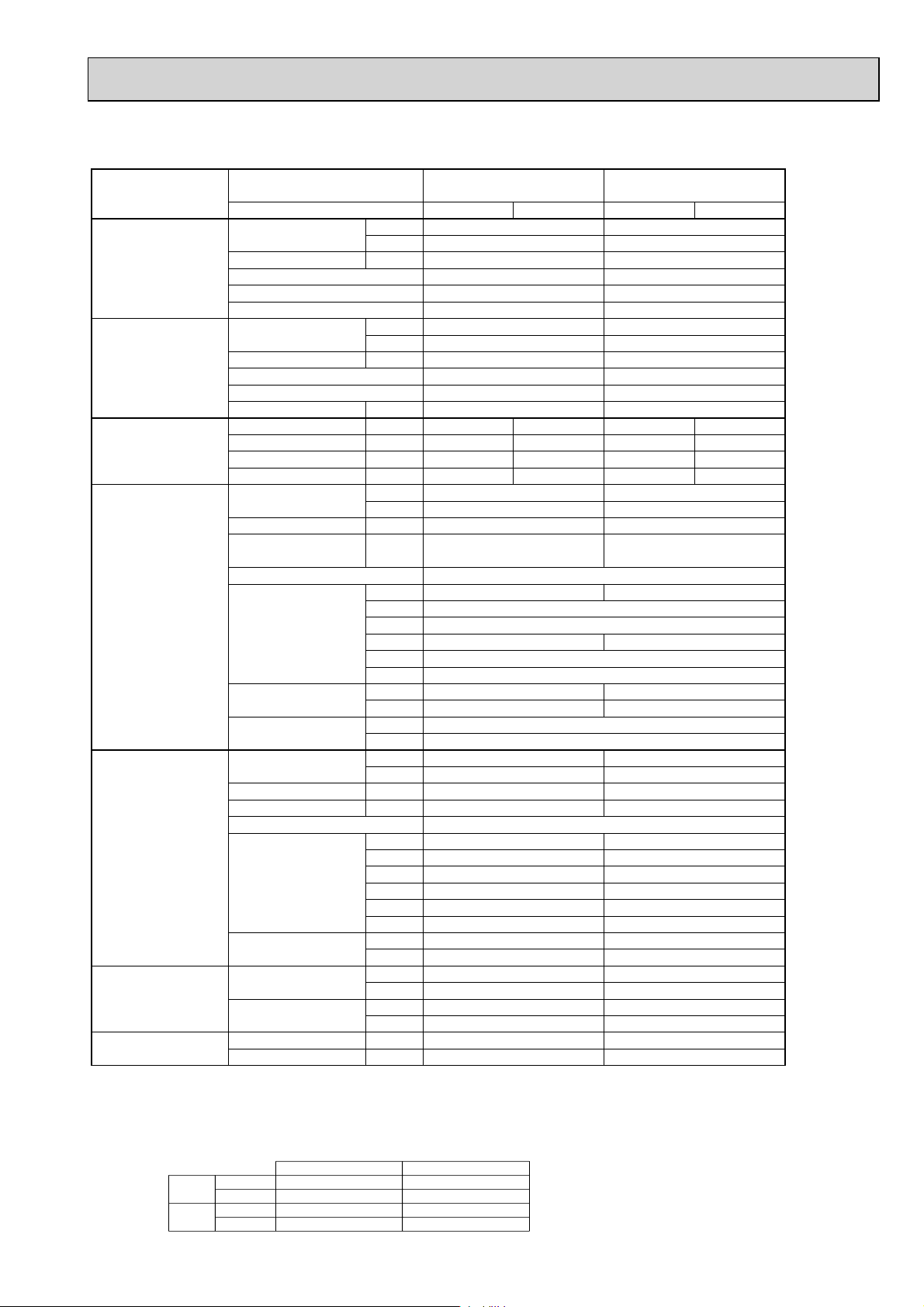
Model name Indoor unit PEAD-RP71GA PEAD-RP100GA
Outdoor unit PUH-P71VHA PUH-P71YHA
PUH-P100VHA PUH-P100YHA
Cooling Capacity Btu/h 27,000 33,100
kW 7.9 9.7
Total input kW 2.97 3.98
EER 2.66 2.44
Energy label class D E
SHF 0.83 0.86
Heating Capacity Btu/h 30,700 39,200
kW 9.0 11.5
Total input kW 3.11 4.09
COP 2.89 2.81
Energy label class D D
Booster heater kW — —
Power supply Phase : 1313
Cycle Hz50505050
Voltage V 230 400 230 400
Breaker size A 32 16 32 16
Indoor unit Air flow CMM 20-25 26.5-33
(
Low-High
)
CFM 706-883 935-1165
External pressure Pa 10/50/70 10/50/70
Sound level dB(A
(
Low-High
)(
)
35-38/37-41/37-43 40-43/42-45/42-46
10/50/70Pa
)(
10/50/70Pa
)
External finish Galvanized sheets
Dimension W : mm 1171 1411
D : mm 740
H : mm 275
W : inch 46-1/8 55-9/16
D : inch 29-1/8
H : inch 10-13/16
Weight kg 42 50
lbs 93 111
Unit drain pipe O.D. mm 32
inch 1-1/4
Outdoor unit Air flow CMM 55 65
CFM 1,940 2,290
Sound level at cooling dB(A
Sound level at heating dB(A
)
)
49 50
50 52
External finish Ivory Munsell 3Y 7.8/1.1
Dimension W : mm 950 950
D : mm 330+30 330+30
H : mm 943 943
W : inch 37-3/8 37-3/8
D : inch 13 + 1-3/16 13 + 1-3/16
H : inch 37-1/8 37-1/8
Weight kg 93 94
lbs 205 207
Refrigerant pipe size Gas side O.D. mm 15.88 15.88
inch 5/8 5/8
Liquid side O.D. mm 9.52 9.52
inch 3/8 3/8
Refrigerant pipe length Height difference m Max. 50 Max. 50
Length m Max. 50 Max. 50
NOTE: 1. Rating conditions (ISO T1)
Cooling Indoor : D.B. 27 (80°F) W.B. 19 (66°F) Outdoor : D.B. 35 (95°F) W.B. 24 (75°F)
Heating Indoor : D.B. 20 (68°F) Outdoor : D.B. 7 (45°F) W.B. 6 (43°F)
Refrigerant piping length (one way) : 5m (16ft.)
2. Guaranteed operating range
Cooling
Heating
Upper limit
Lower limit
Upper limit
Lower limit
D.B. 35°C, W.B. 22.5°C
D.B. 19°C, W.B. 15°C D.B. -5 +
D.B. 28°C
D.B. 17°C D.B. -11, W.B. -12°C
Indoor Outdoor
D.B. 46
D.B. 21, W.B. 15°C
11
3. Guaranteed voltage
198~264V, 50Hz : Single phase
342~457V, 50Hz : 3 phase
4. Above data are based on the indicated voltage
Indoor unit Single phase 230V 50Hz
Outdoor unit
+ If optional Air protect guide installed. D.B.-15
Single phase 230V 50Hz
/ 3 phase 400V 50Hz
Page 12
Model name Indoor unit PEAD-RP71GA PEAD-RP100GA
Outdoor unit PU-P71VHA PU-P71YHA PU-P100VHA PU-P100YHA
Cooling Capacity Btu/h 27,000 33,100
kW 7.9 9.7
Total input kW 2.97 3.98
EER 2.66 2.44
Energy label class D E
SHF 0.83 0.86
Heating Capacity Btu/h — —
kW — —
Total input kW — —
COP — —
Energy label class — —
Booster heater kW — —
Power supply Phase : 1313
Cycle Hz50505050
Voltage V 230 400 230 400
Breaker size A 32 16 32 16
Indoor unit Air flow CMM 20-25 26.5-33
(
Low-High
)
CFM 706-883 935-1165
External pressure Pa 10/50/70 10/50/70
Sound level dB(A
(
Low-High
)(
)
35-38/37-41/37-43 40-43/42-45/42-46
10/50/70Pa
)(
10/50/70Pa
)
External finish Galvanized sheets
Dimension W : mm 1171 1411
D : mm 740
H : mm 275
W : inch 46-1/8 55-9/16
D : inch 29-1/8
H : inch 10-13/16
Weight kg 42 50
lbs 93 111
Unit drain pipe O.D. mm 32
inch 1-1/4
Outdoor unit Air flow CMM 55 65
CFM 1,940 2,290
Sound level at cooling dB(A
Sound level at heating dB(A
)
)
49 50
——
External finish Ivory Munsell 3Y 7.8/1.1
Dimension W : mm 950 950
D : mm 330+30 330+30
H : mm 943 943
W : inch 37-3/8 37-3/8
D : inch 13 + 1-3/16 13 + 1-3/16
H : inch 37-1/8 37-1/8
Weight kg 93 94
lbs 205 207
Refrigerant pipe size Gas side O.D. mm 15.88 15.88
inch 5/8 5/8
Liquid side O.D. mm 9.52 9.52
inch 3/8 3/8
Refrigerant pipe length Height difference m Max. 50 Max. 50
Length m Max. 50 Max. 50
NOTE: 1. Rating conditions (ISO T1)
Cooling Indoor : D.B. 27 (80°F) W.B. 19 (66°F) Outdoor : D.B. 35 (95°F) W.B. 24 (75°F)
Refrigerant piping length (one way) : 5m (16ft.)
2. Guaranteed operating range
Cooling
Upper limit
Lower limit
D.B. 35°C, W.B. 22.5°C
D.B. 19°C, W.B. 15°C D.B. -5 +
Indoor Outdoor
D.B. 46
12
3. Guaranteed voltage
198~264V, 50Hz : Single phase
342~457V, 50Hz : 3 phase
4. Above data are based on the indicated voltage
Indoor unit Single phase 230V 50Hz
Outdoor unit
+ If optional Air protect guide installed. D.B.-15
Single phase 230V 50Hz
/ 3 phase 400V 50Hz
Page 13
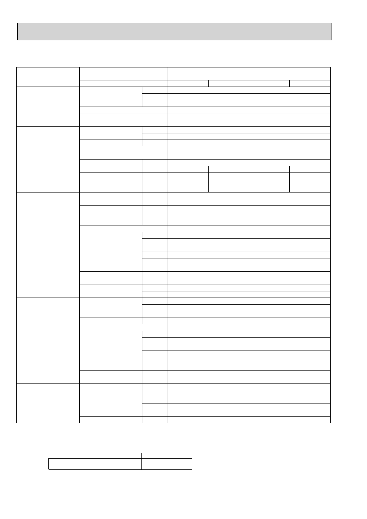
2-3. CEILING-SUSPENDED TYPE
Model name Indoor unit PCA-RP71KA PCA-RP100KA PCA-RP125KA PCA-RP140KA
Outdoor unit
PUH-P71VHA PUH-P71YHA PUH-P100VHA PUH-P100YHA PUH-P125YHA PUH-P140YHA
Cooling Capacity Btu/h 27,300 34,100 42,000 47,800
kW 8.0 10.0 12.3 14.0
Total input kW 2.85 3.56 4.38 5.36
EER 2.81 2.81 2.81 2.61
Energy label class — — — —
SHF 0.76 0.77 0.72 0.75
Heating Capacity Btu/h 30,700 39,200
48,800 58,000
kW 9.0 11.5 14.3 17.0
Total input kW 2.8 3.37 4.45 5.22
COP 3.21 3.41 3.21 3.26
Energy label class — — — —
Booster heater kW — — — —
Power supply Phase : 1313 3
Cycle Hz50505050 50
Voltage V 230 400 230 400 400
Breaker size A 32 16 32 16 25
Indoor unit Air flow CMM 16 - 17 - 18 - 20 22 - 24 - 26 - 28 23-25-27-29
(
Low-Medium2-Medium1-High
)
CFM 565 - 600 - 635 - 705 775 - 850 - 920 - 990
810-885-955-1025
External pressure Pa 0 0 0
Sound level dB(A
(
Low-Medium2-Medium1-High
)
35 - 37 - 39 - 41 37 - 39 - 41 - 43 39-41-43-45 41-43-45-48
)
24-26-29-32
850-920-1025-1130
0
External finish White Munsell 6.4Y 8.9/0.4
Dimension W : mm 1280 1600 1600
D : mm 680 680 680
H : mm 230 230 230
W : inch 50 - 3/8 63 63
D : inch 26 - 3/4 26 - 3/4 26 - 3/4
H : inch 9 - 1/16 9 - 1/16 9 - 1/16
Weight kg 32 36 38 39
lbs 71 79 84 86
Field drain pipe O.D. mm 26
inch 1
Outdoor unit Air flow CMM 55 65 100
CFM 1,940 2,290 3,530
Sound level at cooling dB(A
Sound level at heating dB(A
)
)
49 50 50 51
50 52 52 53
External finish Ivory Munsell 3Y 7.8/1.1
Dimension W : mm 950 950 950
D : mm 330+30 330+30 330+30
H : mm 943 943 1350
W : inch 37-3/8 37-3/8 37-3/8
D : inch 13 + 1-3/16 13 + 1-3/16 13 + 1-3/16
H : inch 37-1/8 37-1/8 53-1/8
Weight kg 93 94 131
lbs 205 207 289
Refrigerant pipe size Gas side O.D. mm 15.88 15.88 15.88
inch 5/8 5/8 5/8
Liquid side O.D. mm 9.52 9.52 9.52
inch 3/8 3/8 3/8
Refrigerant pipe length Height difference m Max. 50 Max. 50 Max. 50
Length m Max. 50 Max. 50 Max. 50
NOTE: 1. Rating conditions (ISO T1)
Cooling Indoor : D.B. 27 (80°F) W.B. 19 (66°F) Outdoor : D.B. 35 (95°F) W.B. 24 (75°F)
Heating Indoor : D.B. 20 (68°F) Outdoor : D.B. 7 (45°F) W.B. 6 (43°F)
Refrigerant piping length (one way) : 5m (16ft.)
2. Guaranteed operating range
Cooling
Heating
Upper limit
Lower limit
Upper limit
Lower limit
D.B. 35°C, W.B. 22.5°C
D.B. 19°C, W.B. 15°C D.B. -5 +
D.B. 28°C
D.B. 17°C D.B. -11, W.B. -12°C
Indoor Outdoor
D.B. 46
D.B. 21, W.B. 15°C
13
3. Guaranteed voltage
198~264V, 50Hz : Single phase
342~457V, 50Hz : 3 phase
4. Above data are based on the indicated voltage
Indoor unit Single phase 230V 50Hz
Outdoor unit
+ If optional Air protect guide installed. D.B.-15
Single phase 230V 50Hz
/ 3 phase 400V 50Hz
Page 14
Model name Indoor unit PCA-RP71KA
PCA-RP100KA
PCA-RP125KA PCA-RP140KA
Outdoor unit
Cooling Capacity Btu/h
Total input kW
EER
Energy label class
SHF
PU-P71VHA PU-P71YHA
kW
PU-P100VHA PU-P100YHA PU-P125YHA PU-P140YHA
27,300 34,100 42,000 47,800
8.0 10.0 12.3 14.0
2.85 3.56 4.38 5.36
2.81 2.81 2.81 2.61
————
0.76 0.77 0.72 0.75
Heating Capacity Btu/h — — — —
kW — — — —
Total input kW — — — —
COP — — — —
Energy label class — — — —
Booster heater kW — — — —
Power supply Phase : 1313 3
Cycle Hz 50 50 50 50 50
Voltage V 230 400 230 400 400
Breaker size A 32 16 32 16 25
Indoor unit Air flow CMM 16 - 17 - 18 - 20 22 - 24 - 26 - 28 23-25-27-29
(
Low-Medium2-Medium1-High
)
CFM 565 - 600 - 635 - 705 775 - 850 - 920 - 990
810-885-955-1025
External pressure Pa 0 0 0
Sound level dB(A
(
Low-Medium2-Medium1-High
)
)
35 - 37 - 39 - 41
37 - 39 - 41 - 43
39-41-43-45 41-43-45-48
24-26-29-32
850-920-1025-1130
0
External finish White Munsell 6.4Y 8.9/0.4
Dimension W : mm 1280 1600 1600
D : mm 680 680 680
H : mm 230 230 230
W : inch 50 - 3/8 63 63
D : inch 26 - 3/4 26 - 3/4 26 - 3/4
H : inch 9 - 1/16 9 - 1/16 9 - 1/16
Weight kg 32 38 38 39
lbs 71 84 84 86
Field drain pipe O.D. mm 26
inch 1
Outdoor unit Air flow CMM 55 65 100
CFM 1,940 2,290 3,530
Sound level at cooling dB(A
Sound level at heating dB(A
)
)
49 50 50 51
————
External finish Ivory Munsell 3Y 7.8/1.1
Dimension W : mm 950 950 950
D : mm 330+30 330+30 330+30
H : mm 943 943 1350
W : inch 37-3/8 37-3/8 37-3/8
D : inch 13 + 1-3/16 13 + 1-3/16 13 + 1-3/16
H : inch 37-1/8 37-1/8 53-1/8
Weight kg 93 94 131
lbs 205 207 289
Refrigerant pipe size Gas side O.D. mm 15.88 15.88 15.88
inch 5/8 5/8 5/8
Liquid side O.D. mm 9.52 9.52 9.52
inch 3/8 3/8 3/8
Refrigerant pipe length Height difference m Max. 50 Max. 50 Max. 50
Length m Max. 50 Max. 50 Max. 50
NOTE: 1. Rating conditions (ISO T1)
Cooling Indoor : D.B. 27 (80°F) W.B. 19 (66°F) Outdoor : D.B. 35 (95°F) W.B. 24 (75°F)
Heating Indoor : D.B. 20 (68°F) Outdoor : D.B. 7 (45°F) W.B. 6 (43°F)
Refrigerant piping length (one way) : 5m (16ft.)
2. Guaranteed operating range
Cooling
Heating
Upper limit
Lower limit
Upper limit
Lower limit
D.B. 35°C, W.B. 22.5°C
D.B. 19°C, W.B. 15°C D.B. -5 +
D.B. 28°C
D.B. 17°C D.B. -11, W.B. -12°C
Indoor Outdoor
D.B. 46
D.B. 21, W.B. 15°C
14
3. Guaranteed voltage
198~264V, 50Hz : Single phase
342~457V, 50Hz : 3 phase
4. Above data are based on the indicated voltage
Indoor unit Single phase 230V 50Hz
Outdoor unit
+ If optional Air protect guide installed. D.B.-15
Single phase 230V 50Hz
/ 3 phase 400V 50Hz
Page 15
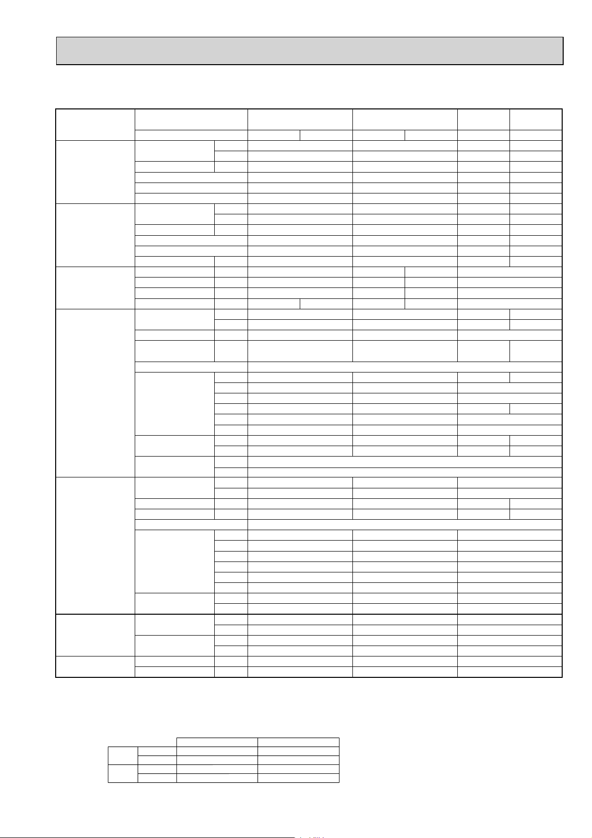
Model name Indoor unit PCA-RP71GA PCA-RP100GA PCA-RP125GA PCA-RP140GA
Outdoor unit
PUH-P71VHA PUH-P71YHA PUH-P100VHA PUH-P100YHA PUH-P125YHA PUH-P140YHA
Cooling Capacity Btu/h 25,900 33,400 42,000 48,500
kW 7.6 9.8 12.3 14.2
Total input kW 2.84 3.55 4.52 5.44
EER 2.68 2.76 2.72 2.61
Energy label class D D D D
SHF 0.74 0.75 0.77 0.75
Heating Capacity Btu/h 30,000 [36,600] 39,200 [47,700]
48,800 [58,200] 58,000 [67,400]
kW 8.8 [10.73] 11.5 [13.98] 14.3 [17.06] 17.0 [19.76]
Total input kW 2.76 [4.69] 3.45 [5.93] 4.72 [7.48] 5.22 [7.98]
COP 3.19 3.33 3.03 3.26
Energy label class D C D C
Booster heater kW [2.1] [2.7] [3.0] [3.0]
Power supply Phase : 1313 3
Cycle Hz50505050 50
Voltage V 230 400 230 400 400
Breaker size A 32 16 32 16 25
Indoor unit Air flow CMM 14-15-16-18 20-21-23-25 27-30-32-34
(
Low-Medium2-Medium1-High
)
CFM 495-530-565-635 705-840-810-885 955-1060-1130-1200
External pressure Pa 0 0 0
Sound level dB(A
(
Low-Medium2-Medium1-High
)
37-39-41-43 40-41-43-45 41-43-45-46 42-44-46-48
)
External finish White Munsell 0.70Y 8.59/0.97
Dimension W : mm 1310 1310 1620
D : mm 680 680 680
H : mm 210 270 270
W : inch 51-9/16 51-9/16 63-3/4
D : inch 26-3/4 26-3/4 26-3/4
H : inch 8-1/4 10-5/8 10-5/8
Weight kg 34 [36] 37 [39.5] 43 [46] 45 [48]
lbs 75 [79] 82 [87] 95 [101] 99 [106]
Field drain pipe O.D. mm 26
inch 1
Outdoor unit Air flow CMM 55 65 100
CFM 1,940 2,290 3,530
Sound level at cooling dB(A
Sound level at heating dB(A
)
)
49 50 50 51
50 52 52 53
External finish Ivory Munsell 3Y 7.8/1.1
Dimension W : mm 950 950 950
D : mm 330+30 330+30 330+30
H : mm 943 943 1350
W : inch 37-3/8 37-3/8 37-3/8
D : inch 13 + 1-3/16 13 + 1-3/16 13 + 1-3/16
H : inch 37-1/8 37-1/8 53-1/8
Weight kg 93 94 131
lbs 205 207 289
Refrigerant pipe size Gas side O.D. mm 15.88 15.88 15.88
inch 5/8 5/8 5/8
Liquid side O.D. mm 9.52 9.52 9.52
inch 3/8 3/8 3/8
Refrigerant pipe length Height difference m Max. 50 Max. 50 Max. 50
Length m Max. 50 Max. 50 Max. 50
NOTE: 1. Rating conditions (ISO T1)
Cooling Indoor : D.B. 27 (80°F) W.B. 19 (66°F) Outdoor : D.B. 35 (95°F) W.B. 24 (75°F)
Heating Indoor : D.B. 20 (68°F) Outdoor : D.B. 7 (45°F) W.B. 6 (43°F)
Refrigerant piping length (one way) : 5m (16ft.)
2. Guaranteed operating range
Cooling
Heating
Upper limit
Lower limit
Upper limit
Lower limit
D.B. 35°C, W.B. 22.5°C
D.B. 19°C, W.B. 15°C D.B. -5 +
D.B. 28°C
D.B. 17°C D.B. -11, W.B. -12°C
Indoor Outdoor
D.B. 46
D.B. 21, W.B. 15°C
3. Guaranteed voltage
198~264V, 50Hz : Single phase
342~457V, 50Hz : 3 phase
4. Above data are based on the indicated voltage
Indoor unit Single phase 230V 50Hz
Outdoor unit
+ If optional Air protect guide installed. D.B.-15
Single phase 230V 50Hz
/ 3 phase 400V 50Hz
15
Page 16
Model name Indoor unit PCA-RP71GA
PCA-RP100GA
PCA-RP125GA PCA-RP140GA
Outdoor unit
PU-P71VHA
PU-P71YHA
PU-P100VHA
PU-P100YHA
PU-P125YHA
PU-P140YHA
Cooling Capacity Btu/h 25,900 33,400 42,000 48,500
kW 7.6 9.8 12.3 14.2
Total input kW 2.84 3.55 4.52 5.44
EER 2.68 2.76 2.72 2.61
Energy label class D D D D
SHF 0.74 0.75 0.77 0.75
Heating Capacity Btu/h — — — —
kW — — — —
Total input kW — — — —
COP — — — —
Energy label class — — — —
Booster heater kW — — — —
Power supply Phase : 1313 3
Cycle Hz50505050 50
Voltage V 230 400 230 400 400
Breaker size A 32 16 32 16 25
Indoor unit Air flow CMM 14-15-16-18 20-21-23-25 27-30-32-34
(
Low-Medium2-Medium1-High
)
CFM 495-530-565-635 705-840-810-885 955-1060-1130-1200
External pressure Pa 0 0 0
Sound level dB(A
(
Low-Medium2-Medium1-High
)
)
37-39-41-43
40-41-43-45
41-43-45-46 42-44-46-48
External finish White Munsell 0.70Y 8.59/0.97
Dimension W : mm 1310 1310 1620
D : mm 680 680 680
H : mm 210 270 270
W : inch 51-9/16 51-9/16 63-3/4
D : inch 26-3/4 26-3/4 26-3/4
H : inch 8-1/4 10-5/8 10-5/8
Weight kg 34 37 43 45
lbs 75 82 95 99
Field drain pipe O.D. mm 26
inch 1
Outdoor unit Air flow CMM 55 65 100
CFM 1,940 2,290 3,530
Sound level at cooling dB(A
Sound level at heating dB(A
)
)
49 50 50 51
————
External finish Ivory Munsell 3Y 7.8/1.1
Dimension W : mm 950 950 950
D : mm 330+30 330+30 330+30
H : mm 943 943 1350
W : inch 37-3/8 37-3/8 37-3/8
D : inch 13 + 1-3/16 13 + 1-3/16 13 + 1-3/16
H : inch 37-1/8 37-1/8 53-1/8
Weight kg 93 94 131
lbs 205 207 289
Refrigerant pipe size Gas side O.D. mm 15.88 15.88 15.88
inch 5/8 5/8 5/8
Liquid side O.D. mm 9.52 9.52 9.52
inch 3/8 3/8 3/8
Refrigerant pipe length Height difference m Max. 50 Max. 50 Max. 50
Length m Max. 50 Max. 50 Max. 50
NOTE: 1. Rating conditions (ISO T1)
Cooling Indoor : D.B. 27 (80°F) W.B. 19 (66°F) Outdoor : D.B. 35 (95°F) W.B. 24 (75°F)
Refrigerant piping length (one way) : 5m (16ft.)
2. Guaranteed operating range
Cooling
Upper limit
Lower limit
D.B. 35°C, W.B. 22.5°C
D.B. 19°C, W.B. 15°C D.B. -5 +
Indoor Outdoor
D.B. 46
16
3. Guaranteed voltage
198~264V, 50Hz : Single phase
342~457V, 50Hz : 3 phase
4. Above data are based on the indicated voltage
Indoor unit Single phase 230V 50Hz
Outdoor unit
+ If optional Air protect guide installed. D.B.-15
Single phase 230V 50Hz
/ 3 phase 400V 50Hz
Page 17
Model name Indoor unit PCA-RP71HA PCA-RP125HA
p
Outdoor unit PUH-P71VHA PUH-P71YHA PUH-P125YHA
Cooling Capacity Btu/h 25,600 42,000
kW 7.5 12.3
Total input kW 2.79 4.55
EER 2.69 2.70
Energy label class
——
SHF 0.74 0.77
Heating Capacity Btu/h 30,400 48,800
kW 8.9 14.3
Total input kW 2.85 5.01
COP 3.12 2.85
Energy label class
Booster heater kW
——
——
Power supply Phase : 13 3
Cycle Hz 50 50 50
Voltage V 230 400 400
Breaker size A 32 16 25
Indoor unit Air flow CMM 17-19 30-38
(
Low-High
)
CFM 600-670 1060-1350
External pressure Pa 0 0
Sound level dB(A
(
Low-High
)
)
34-38 44-50
External finish Stainless steel
Dimension W : mm 1136 1520
D : mm 650
H : mm 280
W : inch 44-3/4 59-7/8
D : inch 25-5/8
H : inch 11
Weight kg 41 56
lbs 90 124
Unit drain pipe O.D. mm 26
inch 1
Outdoor unit Air flow CMM 55 100
CFM 1,940 3,530
Sound level at cooling dB(A
Sound level at heating dB(A
External finish
)
)
49 50
50 52
Ivory Munsell 3Y 7.8/1.1
Dimension W : mm 950 950
D : mm 330+30 330+30
H : mm 943 1350
W : inch 37-3/8 37-3/8
D : inch 13 + 1-3/16 13 + 1-3/16
H : inch 37-1/8 53-1/8
Weight kg 93 131
lbs 205 289
Refrigerant pipe size Gas side O.D. mm 15.88 15.88
inch 5/8 5/8
Liquid side O.D. mm 9.52 9.52
inch 3/8 3/8
Refrigerant pipe length Height difference m Max. 50 Max. 50
Length m Max. 50 Max. 50
NOTE: 1. Rating conditions (ISO T1)
Cooling Indoor : D.B. 27 (80°F) W.B. 19 (66°F) Outdoor : D.B. 35 (95°F) W.B. 24 (75°F)
Heating Indoor : D.B. 20 (68°F) Outdoor : D.B. 7 (45°F) W.B. 6 (43°F)
Refrigerant piping length (one way) : 5m (16ft.)
2. Guaranteed operating range
Cooling
Heating
Upper limit
Lower limit
Upper limit
Lower limit
D.B. 35°C, W.B. 22.5°C
D.B. 19°C, W.B. 15°C D.B. -5 +
D.B. 28°C
D.B. 17°C D.B. -11, W.B. -12°C
Indoor Outdoor
D.B. 46
D.B. 21, W.B. 15°C
17
3. Guaranteed voltage
198~264V, 50Hz : Single phase
342~457V, 50Hz : 3 phase
4. Above data are based on the indicated voltage
Indoor unit Single phase 230V 50Hz
Outdoor unit
Single phase 230V 50Hz
hase 400V 50Hz
/ 3
Page 18
Model name Indoor unit PCA-RP71HA PCA-RP125HA
Outdoor unit PU-P71VHA PU-P71YHA PU-P125YHA
Cooling Capacity Btu/h 25,600 42,000
kW 7.5 12.3
Total input kW 2.79 4.55
EER 2.69 2.70
Energy label class
——
SHF 0.74 0.77
Heating Capacity Btu/h
kW
Total input kW
COP
Energy label class
Booster heater kW
——
——
——
——
——
——
Power supply Phase : 133
Cycle Hz 50 50 50
Voltage V 230 400 400
Breaker size A 32 16 25
Indoor unit Air flow CMM 17-19 30-38
(
Low-High
)
CFM 600-670 1060-1350
External pressure Pa 0 0
Sound level dB(A
(
Low-High
)
)
34-38 44-50
External finish Stainless steel
Dimension W : mm 1136 1520
D : mm 650
H : mm 280
W : inch 44-3/4 59-7/8
D : inch 25-5/8
H : inch 11
Weight kg 41 56
lbs 90 124
Field drain pipe O.D. mm 26
inch 1
Outdoor unit Air flow CMM 55 100
CFM 1,940 3,530
Sound level at cooling dB(A
Sound level at heating dB(A
External finish
)
)
49 50
——
Ivory Munsell 3Y 7.8/1.1
Dimension W : mm 950 950
D : mm 330+30 330+30
H : mm 943 1350
W : inch 37-3/8 37-3/8
D : inch 13 + 1-3/16 13 + 1-3/16
H : inch 37-1/8 53-1/8
Weight kg 93 131
lbs 205 289
Refrigerant pipe size Gas side O.D. mm 15.88 15.88
inch 5/8 5/8
Liquid side O.D. mm 9.52 9.52
inch 3/8 3/8
Refrigerant pipe length Height difference m Max.
50
Max.
50
Length m Max. 50 Max. 50
NOTE: 1. Rating conditions (ISO T1)
Cooling Indoor : D.B. 27 (80°F) W.B. 19 (66°F) Outdoor : D.B. 35 (95°F) W.B. 24 (75°F)
Refrigerant piping length (one way) : 5m (16ft.)
2. Guaranteed operating range
Cooling
Upper limit
Lower limit
D.B. 35°C, W.B. 22.5°C
D.B. 19°C, W.B. 15°C D.B. -5 +
Indoor Outdoor
D.B. 46
18
3. Guaranteed voltage
198~264V, 50Hz : Single phase
342~457V, 50Hz : 3 phase
4. Above data are based on the indicated voltage
Indoor unit Single phase 230V 50Hz
Outdoor unit
+ If optional Air protect guide installed. D.B.-15
Single phase 230V 50Hz
/ 3 phase 400V 50Hz
Page 19
2-4. WALL-MOUNTED TYPE
Model name Indoor unit PKA-RP71KAL PKA-RP100KAL
Outdoor unit PUH-P71VHA PUH-P71YHA PUH-P100VHA PUH-P100YHA
Cooling Capacity Btu/h 27,000 33,400
kW 7.9 9.8
Total input kW 2.84 3.50
EER 2.78 2.80
Energy label class
SHF 0.75 0.73
Heating Capacity Btu/h 30,000 39,200
kW 8.8 11.5
Total input kW 3.08 3.47
COP 2.86 3.31
Energy label class
Booster heater kW
Power supply Phase : 1313
Cycle Hz50505050
Voltage V 230 400 230 400
Breaker size A 32 16 32 16
Indoor unit Air flow CMM 18 - 20 - 22 20 - 23 - 26
(
Low-Middle-High
)
CFM 635 - 705 - 780 705 - 810 - 920
External pressure Pa 0
Sound level dB(A
(
Low-Middle-High
)
)
External finish Munsell 1.0Y 9.2/0.2
Dimension W : mm 1170
D : mm 295
H : mm 365
W : inch 46 - 1/16
D : inch 11 - 5/8
H : inch 14 - 3/8
Weight kg 21
lbs 46
Field drain pipe I.D. mm 16
inch 5/8
Outdoor unit Air flow CMM 55 65
CFM 1,940 2,290
Sound level at cooling dB(A
Sound level at heating dB(A
)
)
External finish
Dimension W : mm 950 950
D : mm 330+30 330+30
H : mm 943 943
W : inch 37-3/8 37-3/8
D : inch 13 + 1-3/16 13 + 1-3/16
H : inch 37-1/8 37-1/8
Weight kg 93 94
lbs 205 207
Refrigerant pipe size Gas side O.D. mm 15.88 15.88
inch 5/8 5/8
Liquid side O.D. mm 9.52 9.52
inch 3/8 3/8
Refrigerant pipe length Height difference m Max. 50 Max. 50
Length m Max. 50 Max. 50
——
——
——
39 - 42 - 45 41 - 45 - 49
49 50
50 52
Ivory Munsell 3Y 7.8/1.1
NOTE: 1. Rating conditions (ISO T1)
Cooling Indoor : D.B. 27 (80°F) W.B. 19 (66°F) Outdoor : D.B. 35 (95°F) W.B. 24 (75°F)
Refrigerant piping length (one way) : 5m (16ft.)
2. Guaranteed operating range
Cooling
Upper limit
Lower limit
D.B. 35°C, W.B. 22.5°C
D.B. 19°C, W.B. 15°C D.B. -5 +
Indoor Outdoor
D.B. 46
19
3. Guaranteed voltage
198~264V, 50Hz : Single phase
342~457V, 50Hz : 3 phase
4. Above data are based on the indicated voltage
Indoor unit Single phase 230V 50Hz
Outdoor unit
+ If optional Air protect guide installed. D.B.-15
Single phase 230V 50Hz
/ 3 phase 400V 50Hz
Page 20
Model name Indoor unit PKA-RP71KAL PKA-RP100KAL
Outdoor unit PU-P71VHA PU-P71YHA PU-P100VHA PU-P100YHA
Cooling Capacity Btu/h 27,000 33,400
kW 7.9 9.8
Total input kW 2.84 3.50
EER 2.78 2.80
Energy label class
——
SHF 0.77 0.77
Heating Capacity Btu/h
kW
Total input kW
COP
Energy label class
Booster heater kW
——
——
——
——
——
——
Power supply Phase : 1313
Cycle Hz50505050
Voltage V 230 400 230 400
Breaker size A 32 16 32 16
Indoor unit Air flow CMM 18 - 20 - 22 20 - 23 - 26
(
Low-Middle-High
)
CFM 635 - 705 - 780 705 - 810 - 920
External pressure Pa 0
Sound level dB(A
(
Low-Middle-High
)
)
39 - 42 - 45 41 - 45 - 49
External finish Munsell 1.0Y 9.2/0.2
Dimension W : mm 1170
D : mm 295
H : mm 365
W : inch 46 - 1/16
D : inch 11 - 5/8
H : inch 14 - 3/8
Weight kg 21
lbs 46
Field drain pipe I.D. mm 16
inch 5/8
Outdoor unit Air flow CMM 55 65
CFM 1,940 2,290
Sound level at cooling dB(A
Sound level at heating dB(A
External finish
)
)
49 50
——
Ivory Munsell 3Y 7.8/1.1
Dimension W : mm 950 950
D : mm 330+30 330+30
H : mm 943 943
W : inch 37-3/8 37-3/8
D : inch 13 + 1-3/16 13 + 1-3/16
H : inch 37-1/8 37-1/8
Weight kg 93 94
lbs 205 207
Refrigerant pipe size Gas side O.D. mm 15.88 15.88
inch 5/8 5/8
Liquid side O.D. mm 9.52 9.52
inch 3/8 3/8
Refrigerant pipe length Height difference m Max. 50 Max. 50
Length m Max. 50 Max. 50
NOTE: 1. Rating conditions (ISO T1)
Cooling Indoor : D.B. 27 (80°F) W.B. 19 (66°F) Outdoor : D.B. 35 (95°F) W.B. 24 (75°F)
Refrigerant piping length (one way) : 5m (16ft.)
2. Guaranteed operating range
Cooling
Upper limit
Lower limit
D.B. 35°C, W.B. 22.5°C
D.B. 19°C, W.B. 15°C D.B. -5 +
Indoor Outdoor
D.B. 46
20
3. Guaranteed voltage
198~264V, 50Hz : Single phase
342~457V, 50Hz : 3 phase
4. Above data are based on the indicated voltage
Indoor unit Single phase 230V 50Hz
Outdoor unit
+ If optional Air protect guide installed. D.B.-15
Single phase 230V 50Hz
/ 3 phase 400V 50Hz
Page 21
Model name Indoor unit PKA-RP71FAL PKA-RP100FAL
Outdoor unit PUH-P71VHA PUH-P71YHA PUH-P100VHA PUH-P100YHA
Cooling Capacity Btu/h 27,000 33,400
kW 7.9 9.8
Total input kW 2.84 3.50
EER 2.78 2.80
Energy label class D D
SHF 0.77 0.77
Heating Capacity Btu/h 30,000 [36,600] 39,200 [46,800]
kW 8.8 [10.73] 11.5 [13.71]
Total input kW 3.08 [5.01] 3.47 [5.68]
COP 2.86 3.31
Energy label class D D
Booster heater kW [2.1] [2.4]
Power supply Phase : 1313
Cycle Hz50505050
Voltage V 230 400 230 400
Breaker size A 32 16 32 16
Indoor unit Air flow CMM 15-20 22-28
(
Low-High
)
CFM 530-705 780-990
External pressure Pa 0
Sound level dB(A
(
Low-High
)
)
39-45 41-46
External finish Munsell 3.4Y 7.7/0.8
Dimension W : mm 1400 1680
D : mm 235
H : mm 340
W : inch 55-1/8 66-1/8
D : inch 9-1/4
H : inch 13-3/8
Weight kg 24 [26] 28 [30]
lbs 53 [57] 62 [66]
Filed drain pipe I.D. mm 20
inch 13/16
Outdoor unit Air flow CMM 55 65
CFM 1,940 2,290
Sound level at cooling dB(A
Sound level at heating dB(A
External finish
)
)
49 50
50 52
Ivory Munsell 3Y 7.8/1.1
Dimension W : mm 950 950
D : mm 330+30 330+30
H : mm 943 943
W : inch 37-3/8 37-3/8
D : inch 13 + 1-3/16 13 + 1-3/16
H : inch 37-1/8 37-1/8
Weight kg 93 94
lbs 205 207
Refrigerant pipe size Gas side O.D. mm 15.88 15.88
inch 5/8 5/8
Liquid side O.D. mm 9.52 9.52
inch 3/8 3/8
Refrigerant pipe length Height difference m Max. 50 Max. 50
Length m Max. 50 Max. 50
NOTE: 1. Rating conditions (ISO T1)
Cooling Indoor : D.B. 27 (80°F) W.B. 19 (66°F) Outdoor : D.B. 35 (95°F) W.B. 24 (75°F)
Refrigerant piping length (one way) : 5m (16ft.)
2. Guaranteed operating range
Cooling
Upper limit
Lower limit
D.B. 35°C, W.B. 22.5°C
D.B. 19°C, W.B. 15°C D.B. -5 +
Indoor Outdoor
D.B. 46
21
3. Guaranteed voltage
198~264V, 50Hz : Single phase
342~457V, 50Hz : 3 phase
4. Above data are based on the indicated voltage
Indoor unit Single phase 230V 50Hz
Outdoor unit
+ If optional Air protect guide installed. D.B.-15
Single phase 230V 50Hz
/ 3 phase 400V 50Hz
Page 22
Model name Indoor unit PKA-RP71FAL PKA-RP100FAL
Outdoor unit PU-P71VHA PU-P71YHA PU-P100VHA PU-P100YHA
Cooling Capacity Btu/h 27,000 33,400
kW 7.9 9.8
Total input kW 2.84 3.50
EER 2.78 2.80
Energy label class D D
SHF 0.77 0.77
Heating Capacity Btu/h
kW
Total input kW
COP
Energy label class
Booster heater kW
——
——
——
——
——
——
Power supply Phase : 1313
Cycle Hz50505050
Voltage V 230 400 230 400
Breaker size A 32 16 32 16
Indoor unit Air flow CMM 15-20 22-28
(
Low-High
)
CFM 530-705 780-990
External pressure Pa 0
Sound level dB(A
(
Low-High
)
)
39-45 41-46
External finish Munsell 3.4Y 7.7/0.8
Dimension W : mm 1400 1680
D : mm 235
H : mm 340
W : inch 55-1/8 66-1/8
D : inch 9-1/4
H : inch 13-3/8
Weight kg 24 28
lbs 53 62
Field drain pipe I.D. mm 20
inch 13/16
Outdoor unit Air flow CMM 55 65
CFM 1,940 2,290
Sound level at cooling dB(A
Sound level at heating dB(A
External finish
)
)
49 50
——
Ivory Munsell 3Y 7.8/1.1
Dimension W : mm 950 950
D : mm 330+30 330+30
H : mm 943 943
W : inch 37-3/8 37-3/8
D : inch 13 + 1-3/16 13 + 1-3/16
H : inch 37-1/8 37-1/8
Weight kg 93 94
lbs 205 207
Refrigerant pipe size Gas side O.D. mm 15.88 15.88
inch 5/8 5/8
Liquid side O.D. mm 9.52 9.52
inch 3/8 3/8
Refrigerant pipe length Height difference m Max. 50 Max. 50
Length m Max. 50 Max. 50
NOTE: 1. Rating conditions (ISO T1)
Cooling Indoor : D.B. 27 (80°F) W.B. 19 (66°F) Outdoor : D.B. 35 (95°F) W.B. 24 (75°F)
Refrigerant piping length (one way) : 5m (16ft.)
2. Guaranteed operating range
Cooling
Upper limit
Lower limit
D.B. 35°C, W.B. 22.5°C
D.B. 19°C, W.B. 15°C D.B. -5 +
Indoor Outdoor
D.B. 46
22
3. Guaranteed voltage
198~264V, 50Hz : Single phase
342~457V, 50Hz : 3 phase
4. Above data are based on the indicated voltage
Indoor unit Single phase 230V 50Hz
Outdoor unit
+ If optional Air protect guide installed. D.B.-15
Single phase 230V 50Hz
/ 3 phase 400V 50Hz
Page 23
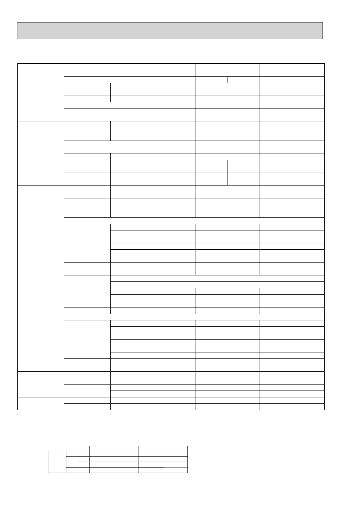
2-5. FLOOR STANDING TYPE
Model name Indoor unit PSA-RP71GA PSA-RP100GA PSA-RP125GA PSA-RP140GA
Outdoor unit
PUH-P71VHA PUH-P71YHA PUH-P100VHA PUH-P100YHA PUH-P125YHA PUH-P140YHA
Cooling Capacity Btu/h 25,900 34,100 42,000 47,800
kW 7.6 10.0 12.3 14.0
Total input kW 2.88 3.66 4.54 5.53
EER 2.64 2.73 2.71 2.53
Energy label class — — — —
SHF 0.73 0.81 0.75 0.74
Heating Capacity Btu/h 30,700 [37,300] 39,200 [47,700]
48,800 [58,200] 58,000 [67,400]
kW 9.0 [10.93] 11.5 [13.98] 14.3 [17.06] 17.0 [19.76]
Total input kW 2.85 [4.78] 3.42 [5.90] 4.41 [7.17] 5.47 [8.23]
COP 3.16 3.36 3.24 3.11
Energy label class — — — —
Booster heater kW [2.1] [2.7] [3.0] [3.0]
Power supply Phase : 1313 3
Cycle Hz 50 50 50 50 50
Voltage V 230 400 230 400 400
Breaker size A 32 16 32 16 25
Indoor unit Air flow CMM 15-18 24-31 26-33 27-35
(
Low-High
)
CFM 530-635 850-1060 920-1165 955-1240
External pressure Pa 0
Sound level dB(A
(
Low-High
)
External finish
)
40-45 44-49 46-51 47-52
White Munsell 0.70Y 8.59/0.97 White Munsell 0.70Y 8.59/0.97 White Munsell 0.70Y 8.59/0.97
Dimension W : mm 600 600 600
D : mm 270 350 350
H : mm 1900 1900 1900
W : inch 23-5/8 23-5/8 23-5/8
D : inch 10-5/8 13-3/4 13-3/4
H : inch 74-13/16 74-13/16 74-13/16
Weight kg 43 [45] 51 [53] 51 [53] 53 [55]
lbs 95 [99] 112 [117] 112 [117] 117 [121]
Field drain pipe I.D. mm 20 20 20
inch 13/16 13/16 13/16
Outdoor unit Air flow CMM 55 65 100
CFM 1,940 2,290 3,530
Sound level at cooling
Sound level at heating
dB(A
dB(A
)
)
49 50 50 51
50 52 52 53
External finish Ivory Munsell 3Y 7.8/1.1
Dimension W : mm 950 950 950
D : mm 330+30 330+30 330+30
H : mm 943 943 1350
W : inch 37-3/8 37-3/8 37-3/8
D : inch 13 + 1-3/16 13 + 1-3/16 13 + 1-3/16
H : inch 37-1/8 37-1/8 53-1/8
Weight kg 93 94 131
lbs 205 207 289
Refrigerant pipe size Gas side O.D. mm 15.88 15.88 15.88
inch 5/8 5/8 5/8
Liquid side O.D. mm 9.52 9.52 9.52
inch 3/8 3/8 3/8
Refrigerant pipe length
Height difference m Max. 50 Max. 50 Max. 50
Length m Max. 50 Max. 50 Max. 50
NOTE: 1. Rating conditions (ISO T1)
Cooling Indoor : D.B. 27 (80°F) W.B. 19 (66°F) Outdoor : D.B. 35 (95°F) W.B. 24 (75°F)
Refrigerant piping length (one way) : 5m (16ft.)
2. Guaranteed operating range
Cooling
Upper limit
Lower limit
D.B. 35°C, W.B. 22.5°C
D.B. 19°C, W.B. 15°C D.B. -5 +
Indoor Outdoor
D.B. 46
23
3. Guaranteed voltage
198~264V, 50Hz : Single phase
342~457V, 50Hz : 3 phase
4. Above data are based on the indicated voltage
Indoor unit Single phase 230V 50Hz
Outdoor unit
+ If optional Air protect guide installed. D.B.-15
Single phase 230V 50Hz
/ 3 phase 400V 50Hz
Page 24
Model name Indoor unit PSA-RP71GA PSA-RP100GA PSA-RP125GA PSA-RP140GA
Outdoor unit PU-P71VHA PU-P71YHA PU-P100VHA PU-P100YHA PU-P125YHA PU-P140YHA
Cooling Capacity Btu/h 25,900 34,100 42,000 47,800
kW 7.6 10.0 12.3 14.0
Total input kW 2.88 3.66 4.54 5.53
EER 2.64 2.73 2.71 2.53
Energy label class — — — —
SHF 0.73 0.81 0.75 0.74
Heating Capacity Btu/h — — — —
kW — — — —
Total input kW — — — —
COP — — — —
Energy label class — — — —
Booster heater kW — — — —
Power supply Phase : 1313 3
Cycle Hz50505050 50
Voltage V 230 400 230 400 400
Breaker size A 32 16 32 16 25
Indoor unit Air flow CMM 15-18 24-31 26-33 27-35
(
Low-High
)
CFM 530-635 850-1060 920-1165 955-1240
External pressure Pa 0
Sound level dB(A
(
Low-High
)
)
40-45 44-49 46-51 47-52
External finish White Munsell 0.70Y 8.59/0.97 White Munsell 0.70Y 8.59/0.97 White Munsell 0.70Y 8.59/0.97
Dimension W : mm 600 600 600
D : mm 270 350 350
H : mm 1900 1900 1900
W : inch 23-5/8 23-5/8 23-5/8
D : inch 10-5/8 13-3/4 13-3/4
H : inch 74-13/16 74-13/16 74-13/16
Weight kg 43 51 51 53
lbs 95 112 112 117
Field drain pipe I.D. mm 20 20 20
inch 13/16 13/16 13/16
Outdoor unit Air flow CMM 55 65 100
CFM 1,940 2,290 3,530
Sound level at cooling dB(A
Sound level at heating dB(A
)
)
49 50 50 51
————
External finish Ivory Munsell 3Y 7.8/1.1
Dimension W : mm 950 950 950
D : mm 330+30 330+30 330+30
H : mm 943 943 1350
W : inch 37-3/8 37-3/8 37-3/8
D : inch 13 + 1-3/16 13 + 1-3/16 13 + 1-3/16
H : inch 37-1/8 37-1/8 53-1/8
Weight kg 93 94 131
lbs 205 207 289
Refrigerant pipe size Gas side O.D. mm 15.88 15.88 15.88
inch 5/8 5/8 5/8
Liquid side O.D. mm 9.52 9.52 9.52
inch 3/8 3/8 3/8
Refrigerant pipe length Height difference m Max. 50 Max. 50 Max. 50
Length m Max. 50 Max. 50 Max. 50
NOTE: 1. Rating conditions (ISO T1)
Cooling Indoor : D.B. 27 (80°F) W.B. 19 (66°F) Outdoor : D.B. 35 (95°F) W.B. 24 (75°F)
Refrigerant piping length (one way) : 5m (16ft.)
2. Guaranteed operating range
Cooling
Upper limit
Lower limit
D.B. 35°C, W.B. 22.5°C
D.B. 19°C, W.B. 15°C D.B. -5 +
Indoor Outdoor
D.B. 46
24
3. Guaranteed voltage
198~264V, 50Hz : Single phase
342~457V, 50Hz : 3 phase
4. Above data are based on the indicated voltage
Indoor unit Single phase 230V 50Hz
Outdoor unit
+ If optional Air protect guide installed. D.B.-15
Single phase 230V 50Hz
/ 3 phase 400V 50Hz
Page 25
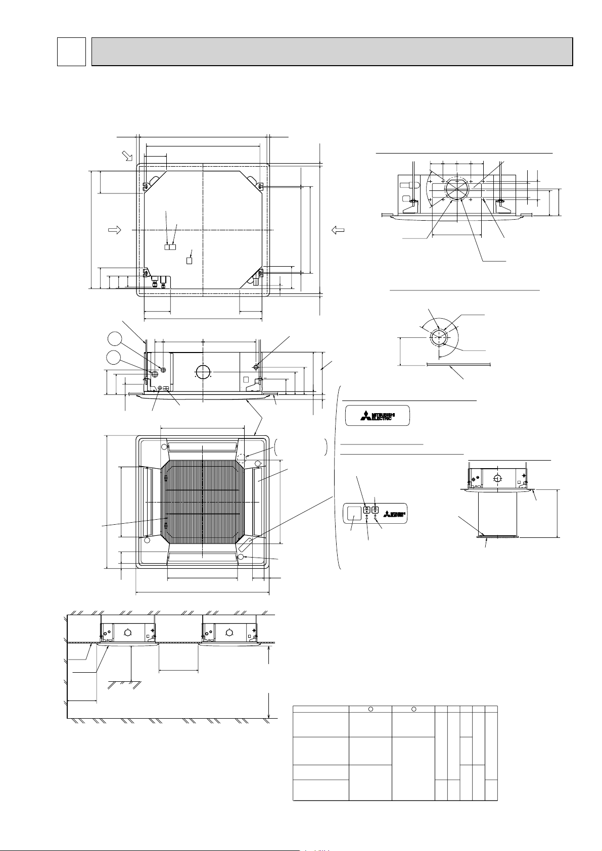
3
OUTLINES AND DIMENSIONS
PLA-RP35BA PLA-RP50BA PLA-RP60BA PLA-RP71BA
PLA-RP100BA PLARP125BA PLA-RP140BA PLA-RP140BA2
Unit : mm
840
Suspension bolt
M10 or W3/8
Suspension bolt
lower edge
Air intake grille
Ceiling
Grille
1500mm
or more
20~45
Fresh air
intake hole
160
Branch duct hole
150
D
C
90
1
2
170
140
+
+
50~70
+
Control wire entry
500
950
Air outlet hole
8336
Indoor unit
1000mm
or more
Obstacle
160
Remote controller
terminal block
Indoor unit/Outdoor unit
connecting terminal block
187.5
M
M
3000mm or more
Floor
Ceiling hole
860~910
810
Suspension bolt pitch
Indoor power supply
terminal block(Option part)
840
37728460
Power supply wire,
Indoor unit/Outdoor unit
connecting wire entry
597
Air intake hole
M
500
Air outlet hole
950
Indoor unit
20~45
24
160
+
Ceiling
Grille
Drain hole
Drain pump clean hole
and Drain emergency
drainage hole
M
597
Vane motor
83
36
1800mm or more
from floor
For high
attachment
20~45
(7.5)(7.5)
+35
620
605
- 5
Suspension bolt pitch
160
Drain pipe
connected to VP-25
A
190
156
105
+
+
0
+5
17
Branch duct hole
860~910
Ceiling hole
Burring hole pitch
Detail drawing of fresh air intake hole
20~45
Connected the attached
drain socket.
()
Keep approximately
10 to 15mm space
between unit ceiling
and ceiling slab.
B35
+
In case of standard grille : PLP-6BA / PLP-6BAMD
158
+
In case of Auto-Grille : PLP-6BAJ
In case of wireless remote controller : PLP-6BALM
Auto vane
(Air outlet)
Air intake hole
Note1. Please choose the Grille from a standard grille, Auto-Grille.
2. As for drain pipe, please use VP-25(O.D. :32 PVC TUBE).
Drain pump inclusion.
Raise is max 850mm from the ceiling.
3. As for suspension bolt, please use M10 or W3/8.
(Procured at local site)
4. Electrical box may be removed for the service purpose.
Make sure to slack the electrical wire little bit for control/ power wires connection.
5. The height of the indoor unit is able to be adjusted with the grille attached.
6. For the installation of the optional high efficiency filter or optional multi-functional casement.
1) Requires E or more space between transom and ceiling for the installation.
2) Add 135 mm to the dimensions + marked on the figure.
3) Optional high efficiency filter must be used jointly with optional multi functional casement.
7. When installing the branch ducts, be sure to insulate adequately.
Otherwise condensation and dripping may occur.
(It becomes the cause of dew drops/Water dew.)
8. As for necessary installation/service space, please refer to the under at figure.
PLA-RP35/50BA
PLA-RP60BA
PLA-RP71BA
PLA-RP100,125,140BA
PLA-RP140BA2
Emergency operation
switch<Cooling>and
Emergency Up/Down switch<Up>
Emergency operation
switch<Heating>and
Emergency Up/Down switch<Down>
Receiver
Models
Refrigerant pipe
···:6.35
Flared connection
···1/4F
Refrigerant pipe
:6.35 / :9.52
Flared connection
1/4F / 3/8F
(compatible)
Refrigerant pipe
···:9.52
Flared connection
···3/8F
DEFROST/STAND BY lamp
Operation lamp
1
Refrigerant pipe
···:12.7
Flared connection
···1/2F
Refrigerant pipe
···:15.88
Flared connection
···5/8F
70
:175
Burring hole
3-:2.8
2
90 100 100 90
350
Burring hole pitch
:125
120
Cut out hole
120
:100
Ceiling
Auto Grille
Air intake grille up/down discharge
L.L Filter
BACDE
80
241 258
87
85 77
298
281
Cut out hole
14-:2.8
Burring hole
:150
Cut out hole
Air intake grille
74
400
440
100
Detail connecting of Branch duct(Both aspects)
130
Ceiling
155
167
++
Max. 4.0m
2525
Page 26
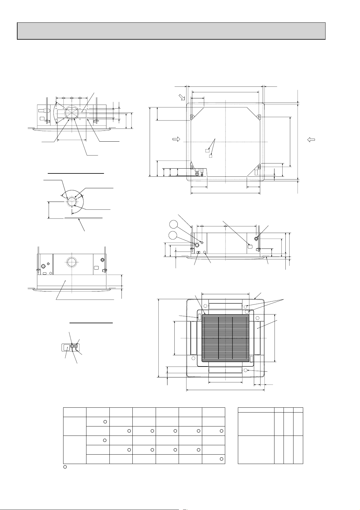
PLA-RP35AA PLA-RP50AA PLA-RP60AA PLA-RP71AA
PLA-RP100AA2 PLA-RP125AA2 PLA-RP140AA2
Unit : mm
90
100 100 90
"
70
W175
3 - W2.8
Burring hole
158
350
Detail drawing of fresh air intake
120"
Branch duct hole
(Cut out hole)
W150
W125
Burring hole pitch
120"
W100
(Cut out hole)
Ceiling surface
100
14 - W2.8
Burring hole
130
167
155
Suspension bolt lower edge
Fresh air intake
159192
Branch duct hole
840
89
98
Suspension bolt M10
or W3/8
1
2
170
140
C
50 - 70
Power line entry
Ceiling hole
860 - 910
810
Suspension bolt pitch
159
Terminal block
197 159
840
Feeding hole
(Drain pump)
Control wire entry
37428660
20 - 4520 - 45
16
Drain pipe
VP-25connection
(O.D.W32)
105
Ceiling surface
605
860 - 91020 - 45 20 - 45
Ceiling hole
Suspension bolt pitch
159
A
B
190
0
+5
30
17
Branch
duct hole
135
0
+5
High efficiency filter
& Fresh air intake casement (option)
17
A (WIRELESS PANEL)
Emergency operation switch (cooling)
Emergency operation switch (heating)
Receiver
Use the current nuts meeting the pipe size of the outdoor unit.
Available pipe size
LIQUID SIDE
GAS SIDE
Factory flare nut attachment to the heat-exchanger.
DEFROST/STAND BY lamp
Operation lamp
RP35, 50
RP60 RP71
:6.35 :6.35 — —
:9.52 :9.52 :9.52 :9.52
:12.7 — — —
:15.88 :15.88 :15.88 :15.88
———:19.05
Air intake grille
A
950
411
Air outlet hole
51 77
RP100, 125, 140
M
M
P35,50,60,71
P100, 125, 140
——
:9.52 :9.52
——
:15.88 —
— :19.05
577
Air intake hole
411
Air outlet hole
950
Grille
M
M
PLA-RP35,50AA
PLA-RP60,71AA
PLA-RP100,125,140AA2
Vane motor
77 51
Models
Drain hole
Auto vane
577
Air intake hole
A
241
258
281
298
B
C
80
84
26
Page 27
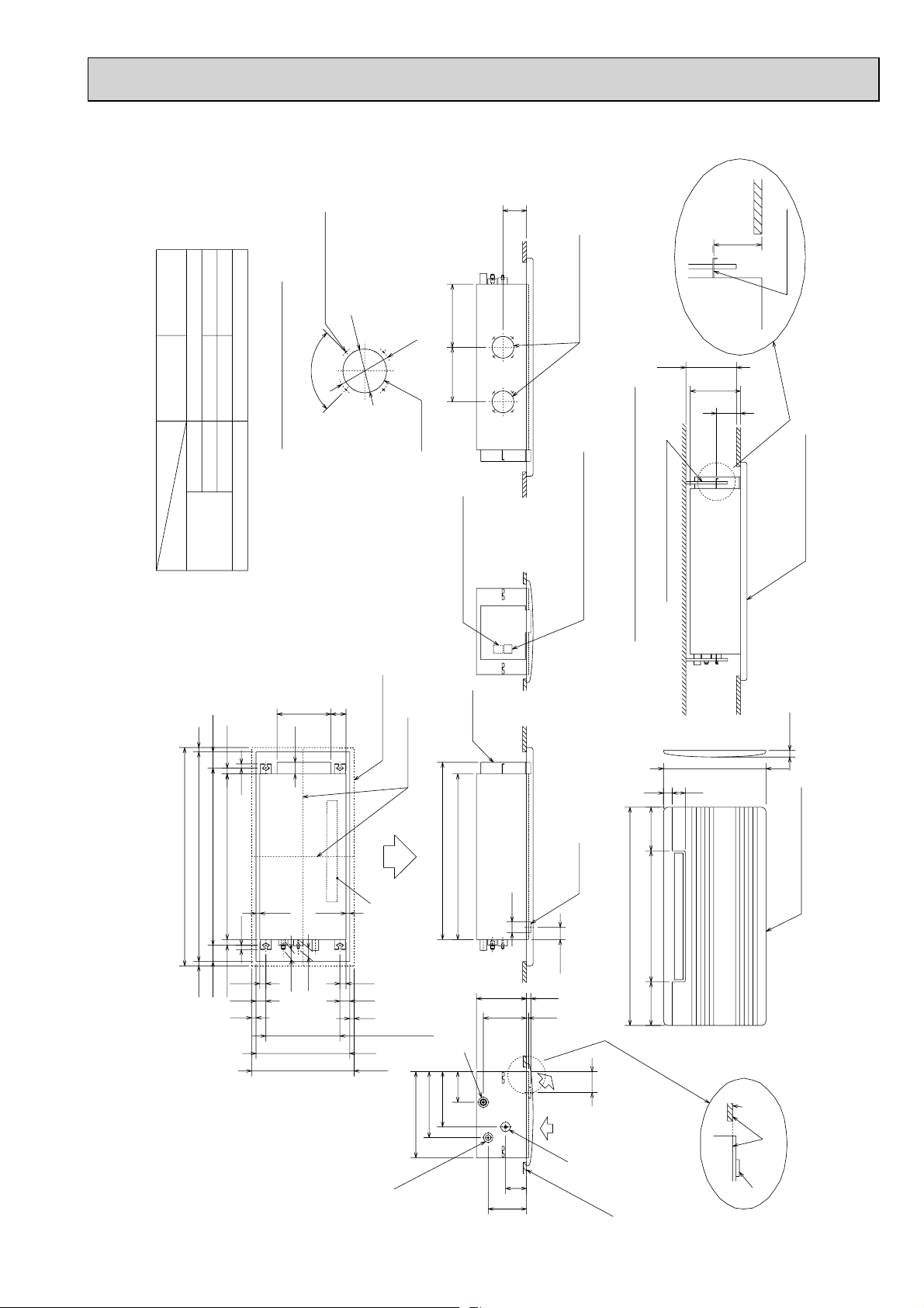
PMH-P25BA PMH-P35BA PMH-P50BA
PMH-P50BA
PMH-P35BA
O.D.W35
PMH-P25BA
O.D.W6.35(1/4") O.D.W9.52(3/8")
PVC pipe:VP-20[O.D.W25(1")]
O.D.W12.7(1/2") O.D.W15.88(5/8")
4-W2.8 Burring hole
100
W
90
W
122
250 288.5
Unit : mm
108
110
mounting plate
Flesh air intake hole
235 or more
230
110
Details of fresh air intake hole
Gas pipe
Liquid pipe
pipe cover
Drainage piping
Refrigerant
piping
74.5
26
20
75926
960 seiling opening20 20
1000 outer side of grille
811 suspension bolt pitch74.5
20
247
69
53
17.517.5
Knock out
outer line of grille
center of unit
812
Air outlet(lower)
Terminal block for
indoor/outdoor connection
elect box
759
W50
Right side
Terminal block for remote controller
suspension bolt(M10 or W3/8)
Installation space required around indoor unit
200600200
drain pan
Panel(grille):PMP-40BM
30
470 outer side of grille
60 40
Panel(grille):PMP-40BM
(56)
Front
43
46
2828
45
20
To p
45
20
340 suspension bolt pitch
430 ceiling opening
470 outer side of grille
302
395
Refrigerant pipe(gas)
Drainage pipe
PVC pipe:VP-20[O.D.W25]
141
254
230
198
(20)
(10)
96
176
(96)
Refrigerant
pipe(liquid)
1000 outer side of grille
Left side
ceiling panel
ceiling
panel
same line
drain pan
Lower view
27
Page 28
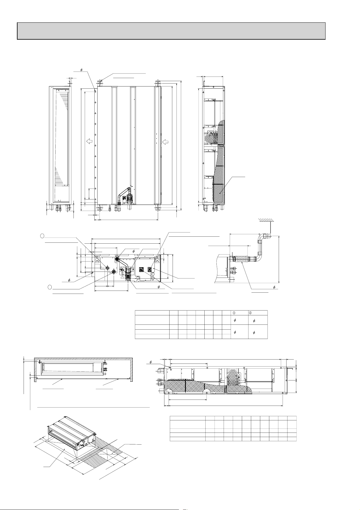
PEAD-RP35, 50, 60, 71, 100, 125, 140JA
2.9
2xE-
15
Suspension bolt hole
4-14x30 Slot
Unit : mm
21018
Air
outlet
D (Duct)
100x(E-1)=F
100
30
20
40
Refrigerant piping
2
Flare connection (liquid)
2×2- 2.9
Refrigerant piping
1
Flare connection (gas)
NOTE 1. Use M10 screw for the Suspension bolt (field supply).
2. Keep the service space for the maintenance at the bottom.
3. This chart indicates for PEAD-RP60
models,which have 2 fans. PEAD-RP35
4. In case that the inlet duct is used, remove the air filter (supplied with
the unit), then install the filter (field supply) at suction side.
57
10
58
23
40
122
100
33
178 (Duct)
•71•
100•125•140JA
•
50JA models have 1 fan.
643 (Suspension bolt pitch)
57
238
10
67
136
356
732
00723
Drain pipe
(O.D.
Air
inlet
Drain pump
32)
Drain pipe(O.D.
(Spontaneous draining)
PEAD-RP35,50JA
PEAD-RP60,71JA
PEAD-RP100,125JA
PEAD-RP140JA
41
32)
Model A
A
B(Suspension bolt pitch)
23
Terminal block
(Remote controller transmission line)
217
250
Control box
Terminal block
(Indoor/Outdoor connecting line)
900 954 860 9
110 0B1154
1400
1454
1600
1654
G21
C
175±5mm
(Actual length)
F
E11D
C
1000
1060
1360
15601416
1000
1300
1500
1200
1500
1700
Air Filter
Less than 300mm
Gas pipe
G
12.7
858800
1058
15.88
1358
1558
Drain hose (I.D. 32)
<accessory>
Liquid pipe
6.35
9.52
Less than 700mm
More than 10mm
Ceiling surface
Make the access door at the appointed position properly for service maintenance.
More than 20mm
50
H
50
Note2
Required space for service and maintenance
250~300
450
Access door
450
than 300
More
777
Access door
J
6
2.9
N-
K
Q
PEAD-RP35,50JA
PEAD-RP60,71JA
PEAD-RP100,125JA
PEAD-RP140JA
Kx(L-1)=M
Qx(R-1)=SP
HModel
54 260 4 780 10 40.5 273 4
1000
1200
1500
1700
330
5454320
37055
M4L49K
990
1280
148012124040
J
11
112 112
SQJ
R
P10N
819
1020
340
440
1320
5
330
1520
5380
28
Page 29
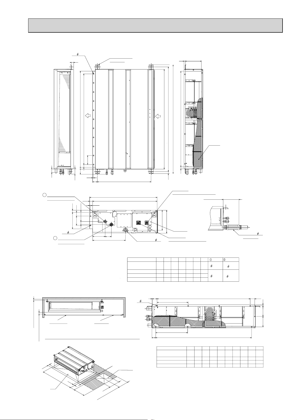
PEAD-RP35, 50, 60, 71, 100, 125, 140JAL
2xE- 2.9
15
Suspension bolt hole
4-14x30 Slot
Unit : mm
21018
Air
outlet
D (Duct)
100x(E-1)=F
100
30
20
2.9
57
58
23
122
40
100
33
178 (Duct)
•71•
100•125•140JAL
•
50JAL models have 1 fan.
10
57
643 (Suspension bolt pitch)
10
136
67
356
40
Refrigerant piping
2
Flare connection (liquid)
2×2-
Refrigerant piping
1
Flare connection (gas)
NOTE 1. Use M10 screw for the Suspension bolt (field supply).
2. Keep the service space for the maintenance at the bottom.
3. This chart indicates for PEAD-RP60
models,which have 2 fans. PEAD-RP35
4. In case of the inlet duct is used,remove the air filter
(supplied with the unit), then install the filter
(field supply) at suction side.
732
00723
Drain pipe(O.D. 32)
PEAD-RP35,50JAL
PEAD-RP60,71JAL
PEAD-RP100,125JAL
PEAD-RP140JAL
Air
inlet
Model A
110 0B115 4
1400
1600
A
217
900 954 860 9
1454
1654
G
C
B(Suspension bolt pitch)
21
23
Terminal block
(Remote controller transmission line)
250
Control box
Terminal block
(Indoor/Outdoor connecting line)
C
1000
1200
1060
1500
1360
1700
15601416
E11D
F
1000
1300
1500
Air Filter
175±5mm
(Actual length)
Gas pipe
G
12.7
858800
1058
15.88
1358
1558
Liquid pipe
6.35
9.52
Drain hose (I.D.
<accessory>
32)
More than 10mm
Ceiling surface
Make the access door at the appointed position properly for service maintenance.
More than 20mm
50
H
50
Note2
Required space for service and maintenance
250~300
450
Access door
450
More than 300
777
Access door
J
6
N-
2.9
K
Q
PEAD-RP35,50JAL
PEAD-RP60,71JAL
PEAD-RP100,125JAL
PEAD-RP140JAL
Kx(L-1)=M
Qx(R-1)=SP
M
330
37055
L49K
990
4
1280
148012124040
HModel
54 260 4 780 10 40.5 273 4
1000
1200
5454320
1500
1700
J
11
112 11 2
SQJ
340
330
R
819
1020
440
1320
5
1520
5380
P10N
29
Page 30
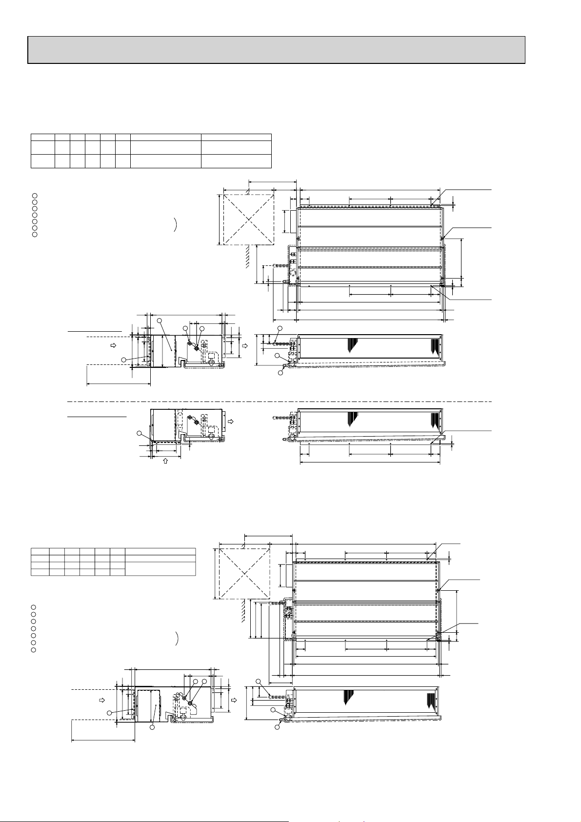
PEAD-RP35EA2
PEAD-RP50EA
PEAD-RP60EA
Unit : mm
21
256
F
:
32)
30
4
10
40
282
176
Model
-
RP35,50
305772
RP60
+ Setting at shipment
Refrigerant piping flare connection (liquid : F copper tube):HP
1
Refrigerant piping flare connection (gas :G copper tube):LP
2
Drain R1(External thread)
3
4
Electrical parts box
5
Drain Pump (Option)
6
Drain Pipe (Option) ... Flexible joint VP-25(I.D.
7
Filter
In case of rear inlet
Keep duct-work length 850mm or more.
Be sure to apply the air filter
near the air inlet grille.
EDCBA
R410A Outdoor unit : 6.35 +
804830
R407C Outdoor unit : 9.52
Outdoor unit (SUZ) : 6.35
104410702902801012
R407C Outdoor unit : 9.52 +
3.5
Air inlet
288
7
3.5
In case of bottom inlet
7
3.5
40
176
15
256
Air inlet
R410A Outdoor unit : 12.7 +
R407C Outdoor unit : 15.88
Set
61 227
1
2
10
450
G
15.88
450
Access door
30640
10
24
35
109
179
Air outlet
Air outlet
Service space:500 or more
50~150
55
197
365~465
159
18
13
75
44
243
6
85
80
45
277
5
3
81BC
10-:3 (RP35,50)
12-:3 (RP60)
10
Lifting bolt hole
(14s22)
56 355
10-:3 (RP35,50)
10
:
3 (RP60)
12-
13E
30
10-:3 (RP35,50)
12-:3 (RP60)
10
29
81
81
A
C
A
D
A
B 81
BC 81
PEAD-RP71EA
PEAD-RP100EA2
PEAD-RP125EA
PEAD-RP140EA
Air inlet
EDCBA
R410A Outdoor unit : 15.88 +
12841310370360
R407C outdoor unit : 19.05158416104704601552RP140
30
30
3.5
40
319
261
181
7
3.5
Model
RP71
RP100,125
+
Setting at shipment
1
Refrigerant piping flare connection (liquid :9.52 copper tube):HP
2
Refrigerant piping flare connection (gas :F copper tube):LP
3
Drain R1 (External thread)
4
Electrical parts box
5
Drain Pump (Option)
6
Drain Pipe (Option) ... Flexible joint VP25(I.D.:32)
7
Filter
2801012
1252
Keep duct-work length 850mm or more.
Be sure to apply the air filter
near the air inlet grille.
282
F
15.8810441070290
Set
680
4
Service space:500 or more
29
365~465
122
45
307
323
50~150
81
55
197
308
81
13
44
75
243
6
113
5
3
A
C B
CB81
A
E 13
450
Access door
450
30
1053 169
2
1
35
20
210
140
Air outlet
81
12-:3
10
Lifting bolt hole
(14x22)
375
80
10
30D
12-:3
30
Page 31

PEAD-RP60GA
PEAD-RP71GA
PEAD-RP100GA
Unit : mm
Model
RP60
RP71
RP100
+ Setting at shipment
ABCDE
1125
1090
1125
1090
1365
1330
1050
1050
1290
1012
1012
1252
FG H J
7
840
840
7
1080
9
Outdoor unit(SUZ) : 6.35
8
Other outdoor unit : 9.52 +
8
10
9.52
9.52
R410A Outdoor unit : 15.88 +
R407C Outdoor unit : 19.05
15.88
15.88
31
Page 32
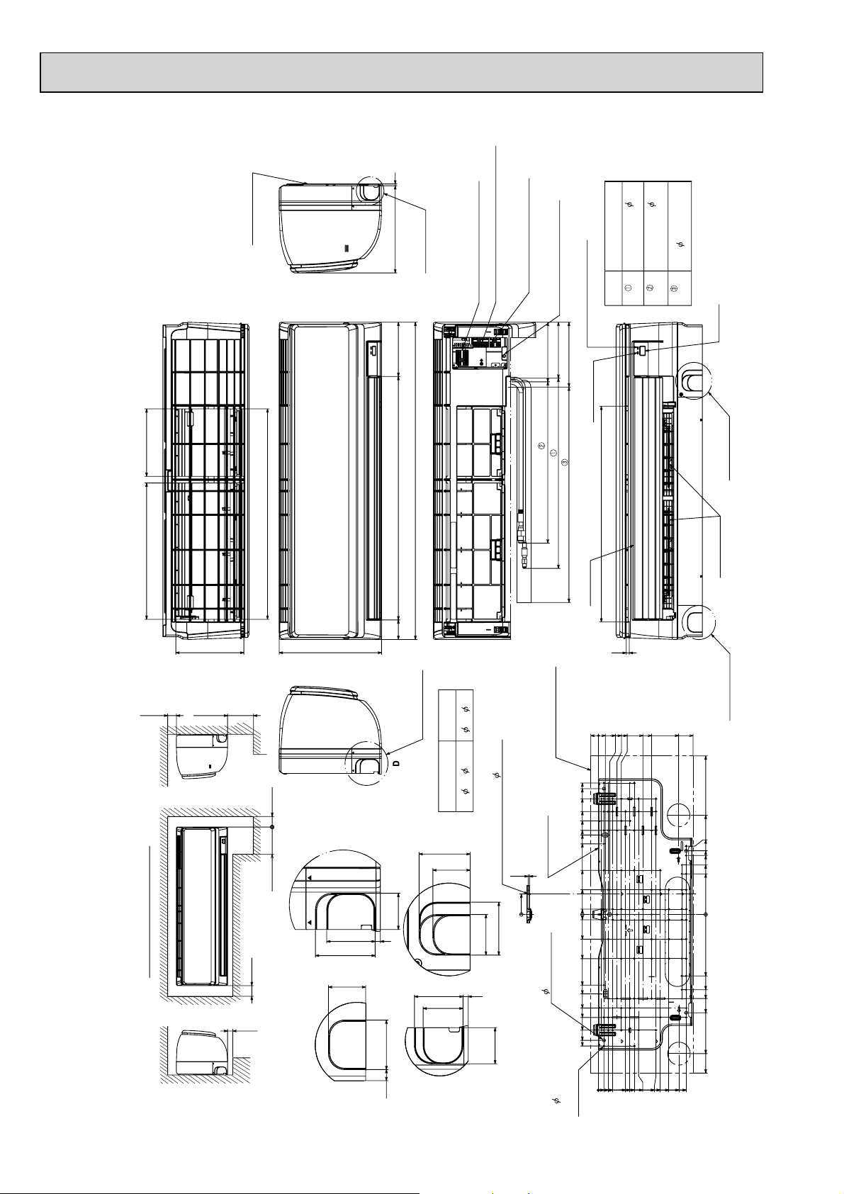
PKA-RP35HAL
PKA-RP50HAL
Unit : mm
A
5
12.7
Top side
192
387
197
Mount board
Right side
Front side
599
295
249
Knockout hole
for right piping
155
898
688
Front side (Grille open)
55
Terminal block for
Terminal block for outdoor unit
MA-remote controller (option)
Terminal block for power supply (option)
(cooling/heating)
Emergency operation switch
DEFROST/STAND BY lamp
158
169
184
Operation lamp
457 Gas pipe
Under side
539 Liquid pipe
612
610 Drain hose
Vane (auto)
Size
Flared connection : 1/4F
Refrigerant pipe :
Flared connection : 1/2F
Refrigerant pipe : 6.35
Gas pipe
Liquid pipe
8
16 O.D
Drain hose
Receiver
B
Knockout hole
for lower piping
Louver (manual)
C
55mm or greater with left
or rear left pipng or drain
pump installation.
Min.50
Required space (Indoor unit)
Min.250
Min.150
Min.220
69
Min.50
550mm or greater with optional
drain pump installation.
drain pump installation.
250mm or greater with optional
Min.7
Knockout hole for piping
80
for left piping
Knockout hole
Left side
D
43
56
6
43
C
56
12.5
65~
Through hole
65~ 80
Sleeve
(purchased locally)
59
43
B
46
56
6
46
A
Indoor unit outline
372.3
356.3
327.5
291.5
265
238
225
200
125
Mount board
3.8
Center measurement hole 2.5
58
0
60
43
70
15
0
15
70
125
200
9 Bolt hole
225
4-
265
291.5
327.5
356.3
372.3
5.1
screw hole
77-
Tapping
21.8020
0
16
28.5
32.7
41
53.5
78.5
66
91
128.5
116
103.5
153.5
166
178.5
203.5
231.5
253.5
232.5
273.2
0
Knockout hole
for lower piping
449
281
193.5
180.3
167
140
115
174
213
238
278.3
394
449
32
Page 33
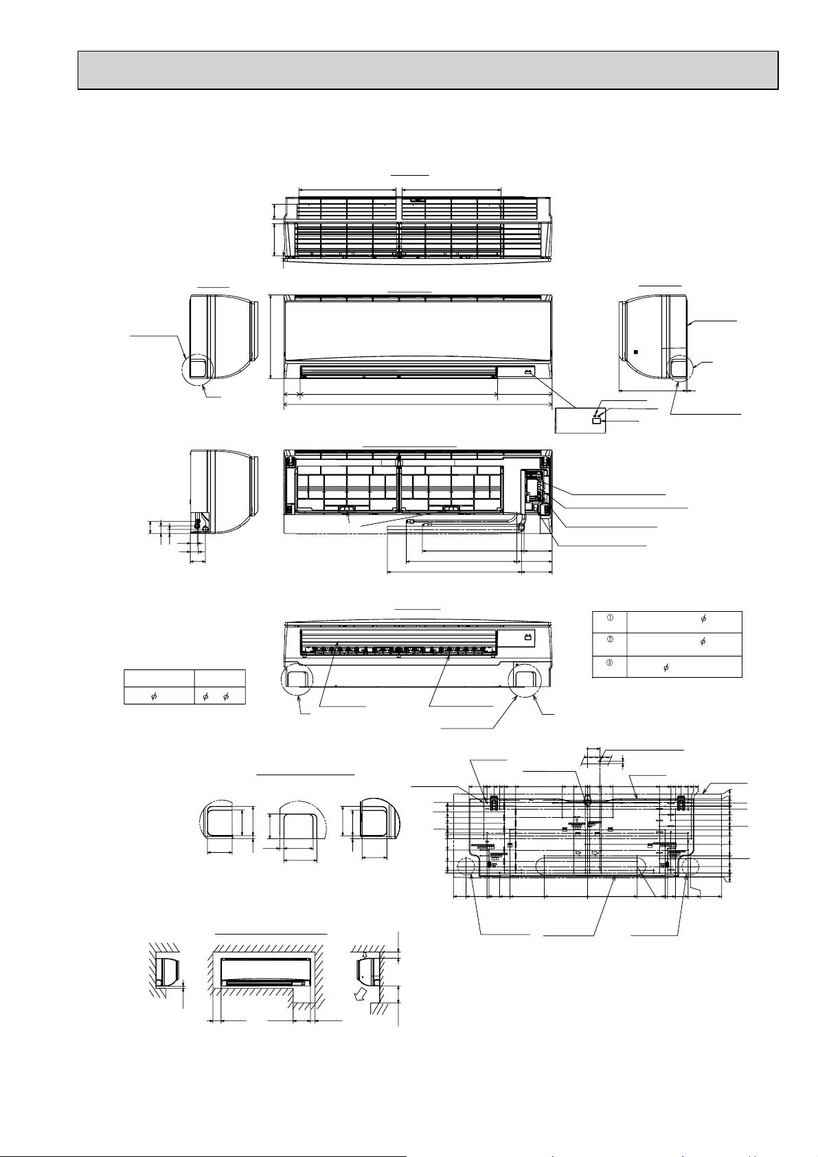
PKA-RP60KAL
PKA-RP71KAL
PKA-RP100KAL
Left side
65.2
140.3
Unit : mm
Top side
423.7
11
Front side
431.7
Right side
Knockout hole
for left piping
53
30
32
18
35
Sleeve
(purchased locally)
75
A
66
Through hole
75~
80
Knockout hole for piping
C
67
77
65
65
10.7
7.8
Required space (Indoor unit)
365
Mount board
C
74
(855)
117 0
241
Operation lamp
295
DEFROST/STAND BY lamp
Receiver
5
Knockout hole for
right piping
Front side (Grille open)
Terminal block for outdoor unit
Terminal block for power supply (option)
Terminal block for
Filter hook
444 (Gas pipe)
482 (Liquid pipe)
585 (Drain hose)
Under side
Vane (auto)
B
AB
77
67
77
87
7.8
Air inlet
65
Min. 48
Louver (manual)
Knockout hole
for lower piping
4-9 Bolt hole
75-5.1
Tapping screw hole
15.5
25
100
279.5
108 mm or greater with left or
rear left piping or drain pump
installation
517.4
0
50
75
117
125
142
192
242
292
585
530.5
408.5
439
454
364
384
439
384
339
430.5
Wall hole for
left rear piping
Temporarily fixing hole
314
MA-remote controller (option)
Emergency operation switch
(cooling/heating)
123
154
134
B
110
189
Knockout hole for
rear piping
(75×480)
Piping connection department
Liquid pipe
Gas pipe
Refrigerant pipe : 9.52
Flared connection : 3/8F
Refrigerant pipe : 15.88
Flared connection : 5/8F
Drain hose
0
54
Center measurement hole 2.5
3
Mount board
10
60
110
60
0
10
R37.5
0
216.5
Wall hole for
right rear piping
16 O.D
364
314
339
384
349.2
384.5
408.5
465.5
439
454
439
449.2
Indoor unit outline
54
32
25
12.5
0
12.5
37.5
62.5
87.5
104.5
129.5
167
217
229.5
264
292
308.5
311
585
Min. 7
550 mm or greater with optional
265 mm or greater with optional
drain pump installation
drain pump installation
Air outlet
Min. 220Min. 72.4
Min. 50.5
Min. 250
33
Page 34
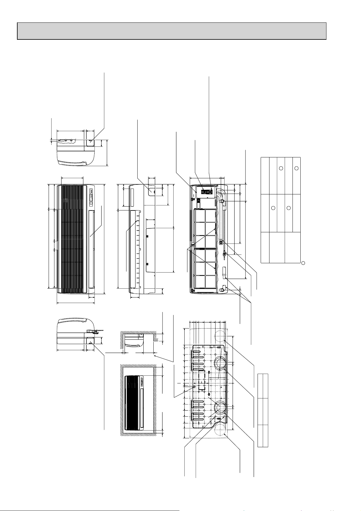
PKA-RP35GAL
BYOFF
ON STAND
HEATCOOL
OFF BY
ON STAND
COOL HEAT
r.SLI
mm
MITSUBISHI ELECTRIC
r.S
L
I
mm
MITSUBISHI ELECTRIC
Knockout hole for right piping
Refrigerant pipe.Drain pipe.
Wiring hole
21
Right side
Less than 15
70
245
60
235
Auto vane
Front view
Air intake
Air intake
Air intake
Air intake
198
53
340
715 225
340 80 280 233
990
21
Left side
Knock out hole for left piping
Refrigerant pipe.Drain pipe.Wiring hole.
60
70
245
(Necessary clearance for
Unit installation)
Right side
Allowing clearances
Front view
Less than 130
50 or more 150 or more
180 or more 30 or more
for bolts
Left-rear
piping hole
left-rear piping
R52.5
R52.5
Installation plate
balance point hole
Details of installation plate
49-:5hole
for tapping screw
Knockout hole for
right-rear piping
Right-rear
piping hole
Unit center
14-:14hole
Knockout hole for
425
420
170
190
210
230
0
322
0355580130
190
230
272
310
0
35
95
150
205
260
320
345
495
20
75
135
190
245
300
360
405
495
32
0
+1 Sleeves are available on the market.
+2 This size shows the lower end of through hole.
:90~:100:90
Through hole
Sleeve +1
35,50
Model
R52.5
R52.5
Gas pipe
Liquid pipe
Terminal block for
Terminal block to
outdoor unit
Filter grip
Service panel
(Power supply access)
(Flexible hose total length800)
(Right side piping
installation)
(Left side piping
installation)
Unit drain pipe O.D.20
Front view(to open the grille)
700
449
86
581 54
31 280
35
Knockout hole for under piping
Refrigerant piping.Drain pipe.
Wiring hole
12-Louvers(manual)
Air outlet
Lower side
80
50
395400
190
60
70 35
79
160 40
235
705
power supply (Heater (PKH-P35/50GALH only))
153
GAS SIDE
LIQUID SIDE
RP35,50
P35,50
:6.35
:9.52
:12.7
:15.88
—
:9.52—:15.88
Use the current nuts meeting the pipe size of the outdoor unit.
Available pipe size
: Factory flare nut attachment to the heat - exchanger.
PKA-RP50GAL
Unit : mm
34
Page 35
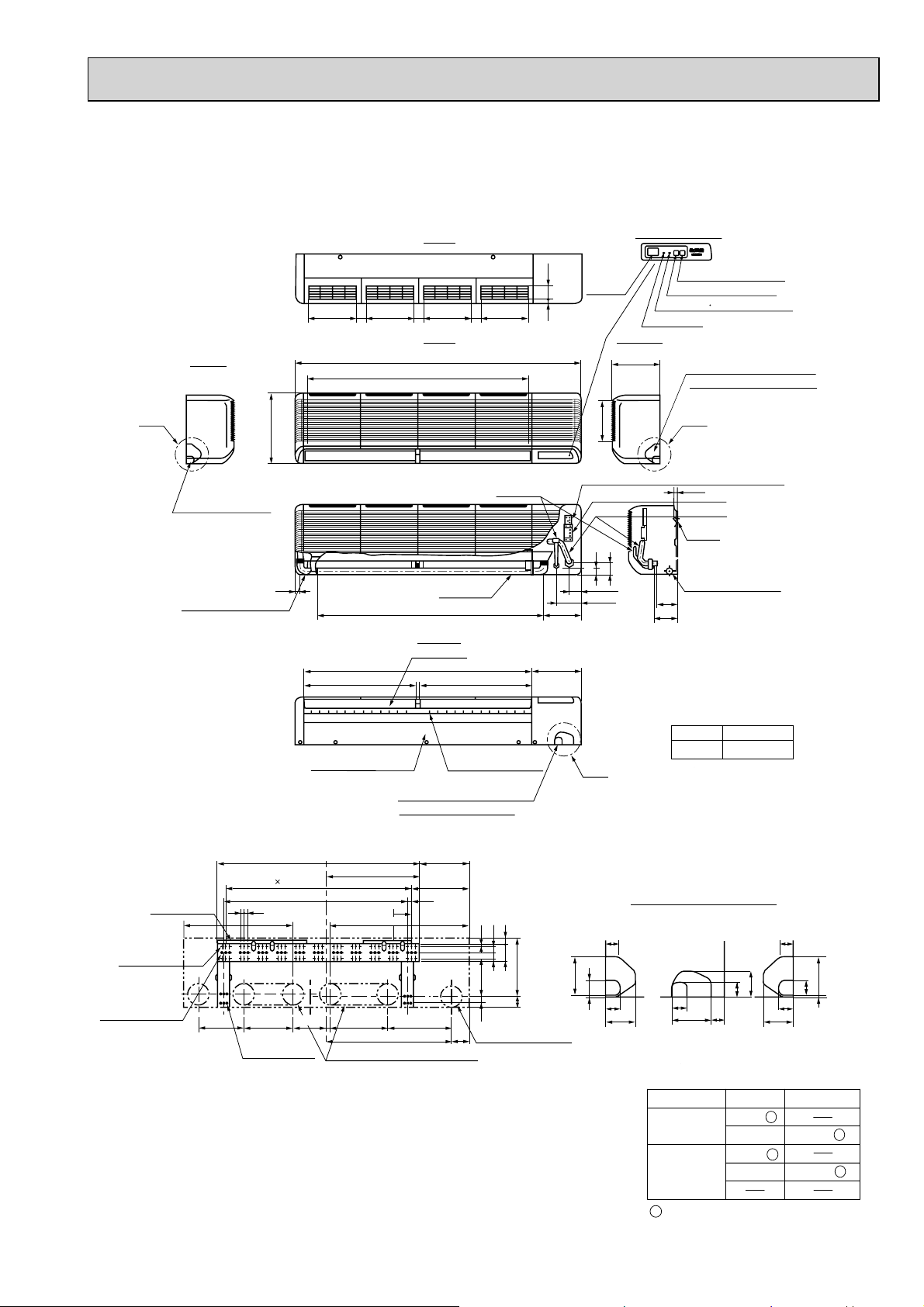
PKA-RP50FAL2
)
PKA-RP60FAL
Unit : mm
A
Left side
Knockout hole for
left piping
Drain hose for
left-hand side piping
340
To p
62.5
Receiving
section
235
235
45
235
45
235
45
13
Front
1400
Air intake
1090
197
Liquid pipe
Terminal block for indoor/outdoor connecting line
42
25
1110
Air outlet
552
Drain hose
Lower side
Auto vanes
112 0
552
Air outlet
183
240
55
120
(Liquid pipe)
Display section
Defrosting Initial heating lamp
Power lamp
Right side
235
58
(Gas pipe)
107
111
Liquid pipe :9.52(3/8F)
Gas pipe :15.88(5/8F)
Emergency switch(Heat)
Emergency switch(Cool)
Knockout hole for right piping
Refrigerant pipe. Drain pipe
C
15
Terminal block for heater (PKH only
Gas pipe
Bolt
Drain hose O.D.20
Wall fixture
66-ø6 hole for
tapping screw
32-ø12 hole for bolt
225
Under panel
Removable at left-hand
side piping
Unit center
990
10 91=(910)
900
18
18
Drainage range
on left-hand side
240 280 314
12-ø6 hole for
tapping screw
Drainage range
on right-hand side
180
Range for left rear piping opening
Knockout hole for under-piping
Refrigerant pipe. Drain pipe
245
455
285
19
91
610
Louvers (manual)
2980
3030
10
18430
90
Rear piping opening
280
60
Sleeve +1
+
B
1 Sleeves are available on the market.
:90
Through hole
:90~ :100
Use the current nuts meeting
the pipe size of the outdoor unit.
Knockout hole for wiring
AB C
30
100
439
37
74
39
98
65
37
32
74
Available pipe size
RP50
LIQUID SIDE
GAS SIDE
:
:
:
:
6.35
9.52
12.7
15.88
30
100
39
37
4
RP60,71 / P60,71
:
9.52
:
15.88
35
:Factory flare nut attachment
to the heat-exchanger.
Page 36
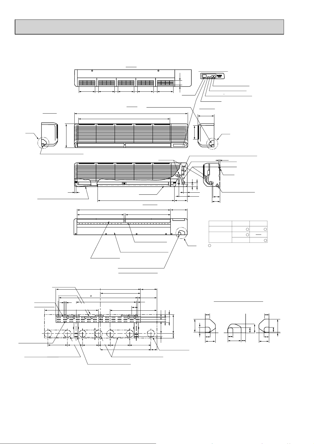
PKA-RP100FAL
)
Unit : mm
Left side
A
340
Knockout hole for left piping
Drain hose for left-hand side piping
To p
Display section
62.5
Emergency switch(Heat)
235
235
45
235
45
235
45
Front
235
45
Knockout hole for right piping
Receiving
13
section
1680
Air intake
1370
197
Liquid pipe
Terminal block for indoor/outdoor connecting line
42
25
1400
Air outlet
694
Under panel
(Removable at left-hand side piping)
Auto vane
1110
Drain hose
Drain hose
Lower side
Air outlet
694
Louvers (manual)
240
183
(Gas pipe)
55
120
(Liquid pipe)
B
Emergency switch(Cool)
Defrosting Initial heating lamp
Power lamp
Right side
235
C
15
Terminal block for heater (PKH only
Gas pipe
Bolt
58
Drain hose O.D.20
102
111
Use the current nuts meeting the pipe size
of the outdoor unit.
Available pipe size
RP100
LIQUID SIDE
GAS SIDE
:9.52
:15.88
:19.05
: Factory flare nut attachment to the
heat-exchanger.
P100
:9.52
:19.05
84-ø6 hole for
tapping screw
41-ø12 hole for bolt
Unit out line
Wall fixture
18
18
Drainage range
on left-hand side
295 225
Knockout hole for under-piping
Refrigerant pipe. Drain pipe
Unit center
1270
13 91=(1183)
240 280 314
595
900
Drainage range
on right-hand side
180
91
750
Range for left rear piping openingRange for left rear piping opening
12-ø6 hole for tapping screw
245
285
19
2980
10
3030
18430
90
Rear piping opening
280
60
100
439
Knockout hole for wiring
AB C
30
37
39
74
37
32
98
30
65
100
39
37
74
4
36
Page 37
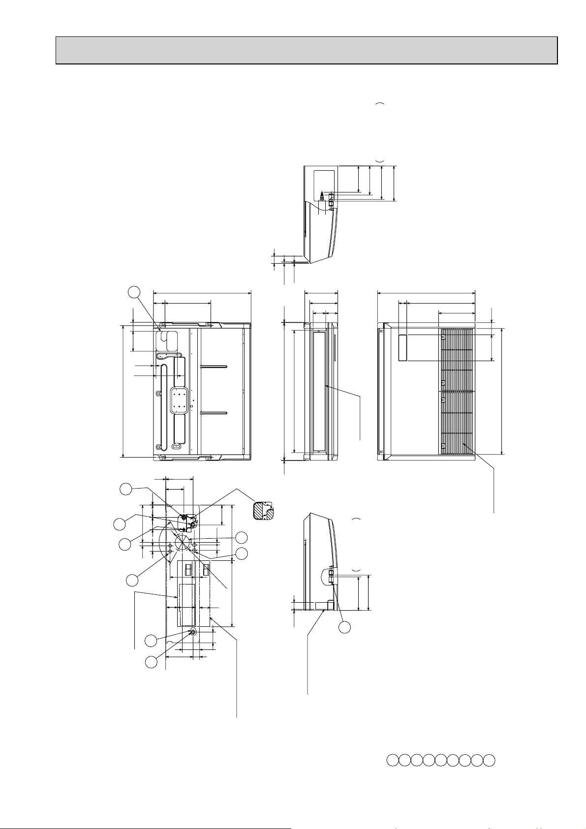
PCA-RP50KA
62140
Unit : mm
When drain socket
is installed
(Drainage)
(gas ø12.7)
(liquid ø6.35)
184
203
233
246
drain pump (option parts),
NOTES.
51
5
10
6
80
18
150
320
680
2
0
6
853
9
230
195
88
84
57
1.Use M10 or W3/8 screw for anchor bolt.
680
476
refrigerant pipe will be only upward.
2.Please be sure when installing the
254
182 85
878
917(Suspension bolt pitch)
1
4
1
85 86 2
26024
120°
5
38
8
[FRONT VIEW]
Electrical box
Ceiling
3
2
126
190
190
169
124 76
Air outlet
2
Air intake
138
18
387
7
38
37
75
121
46
(71)
ø125
9
When drain socket
is installed
(Drainage)
461
48
8
(The heat exchanger might be clogged because of dust)
Then put the independent piece back in initial position.
In case of the rear pipe arrangement, make sure to
remove the shaded portions from the independent piece.
233
246
2
Electrical box
is pulled down
When electrical box
37
Refrigerant-pipe connection(gas pipe side/flared connection)
Drainage pipe connection(for the left arrangement)
Drainage pipe connection(26mmI.D.)
2
1
Refrigerant-pipe connection(liquid pipe side/flared connection)
Knockout hole for left drain-piping arrangement
3
Knockout hole for upper drain pipe arrangement
Knockout hole for fresh air intake ø100
Knockout hole for wiring arrangement 2-ø26
Knockout hole for wiring arrangement 2-ø22
5
4
7
6
Accessory···Drain socket (I.D. 26)
8
9
Page 38
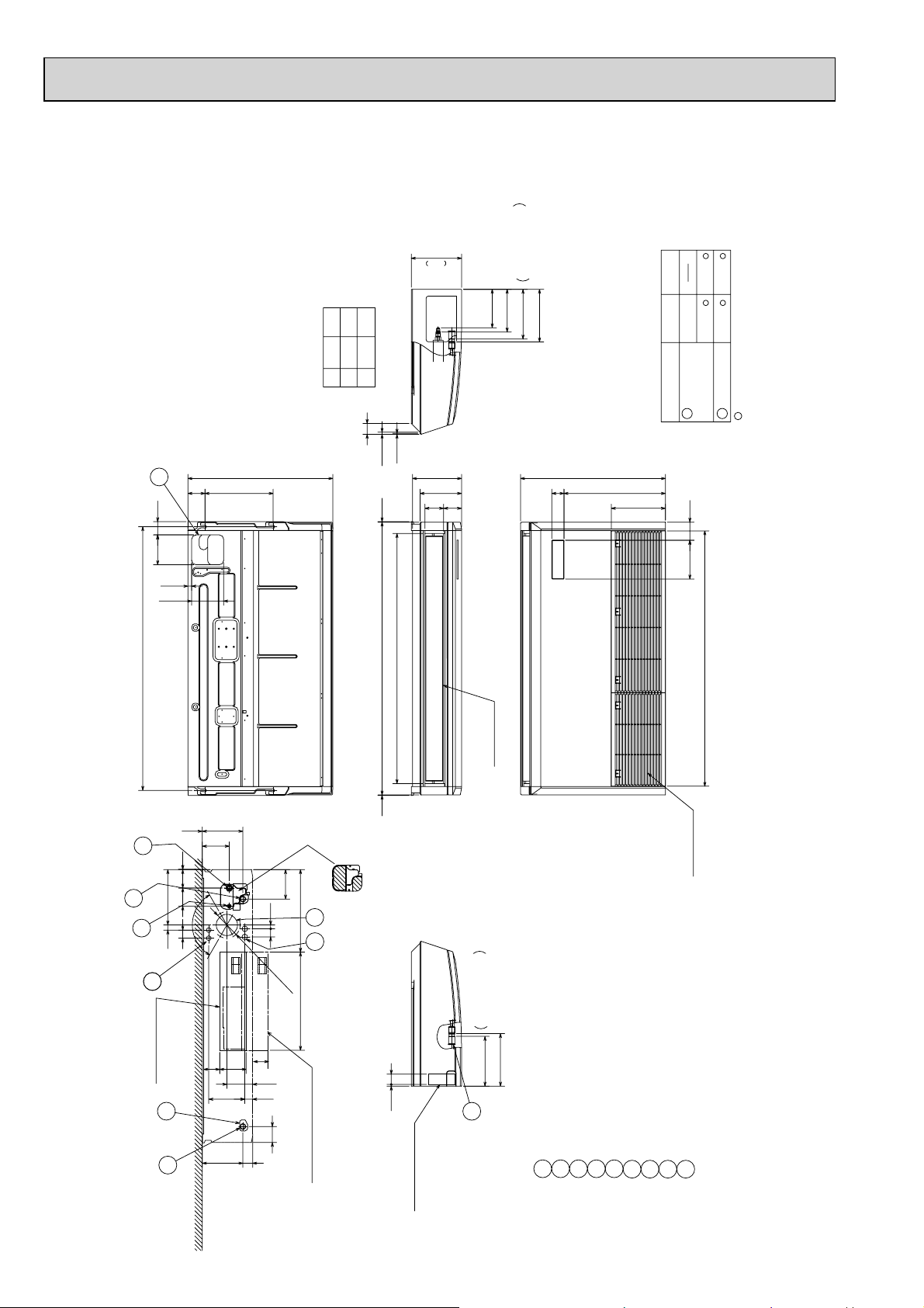
PCA-RP60KA
PCA-RP71KA
Unit : mm
62140
236
71
180
200
60
179
203
A
B
51
5
6
80
18
150
680
320
10
230
208212
1173
195
88
84
When drain socket
(liquid )
(gas ø15.88)
A
B
233
is installed
(Drainage)
246
NOTES.
drain pump (option parts),
1.Use M10 or W3/8 screw for anchor bolt.
2.Please be sure when installing the
680
57
Available pipe size
refrigerant pipe will be only upward.
Use the current nuts meeting the pipe size of the outdoor unit.
476
254
ø9.52
RP71
ø6.35
ø9.52
RP60
5 LIQUID SIDE
182 85
1198
ø15.88
ø15.88
:Initial flare nut size
4 GAS SIDE
1237(Suspension bolt pitch)
4
1
26024
5
8
8
126
85 86 2
120°
38
Ceiling
[FRONT VIEW]
Electrical box
3
2
190 1
124 76
16937
46 190
138
18
387
7
38
(71)
121
75
9
ø125
461
In case of the rear pipe arrangement, make sure to
Then put the independent piece back in initial position.
remove the shaded portions from the independent piece.
When electrical box
is pulled down
Air outlet
When drain socket
is installed
(Drainage)
246
233
48
8
(The heat exchanger might be clogged because of dust)
2
Refrigerant-pipe connection(gas pipe side/flared connection)
Drainage pipe connection(for the left arrangement)
Knockout hole for left drain-piping arrangement
Drainage pipe connection(26mmI.D.)
2
1
Refrigerant-pipe connection(liquid pipe side/flared connection)
Knockout hole for upper drain pipe arrangement
5
3
4
6
Electrical box
Air intake
Knockout hole for wiring arrangement 2-ø26
Knockout hole for fresh air intake ø100
Knockout hole for wiring arrangement 2-ø22
Accessory···Drain socket (I.D. 26)
7
8
Flare nut ø6.35 (RP60 only)
9
38
Page 39

PCA-RP100KA
PCA-RP125KA
PCA-RP140KA
236
When drain socket
(gas ø15.88)
(liquid ø9.52)
180
200
233
is installed
(Drainage)
246
Unit : mm
6
62
140
18
150
(Suspension bolt pitch)
1557
4
1
85 86 2
260
°
120
5
38
24
88
Ceiling
76
Electrical box
[FRONT VIEW]
80
126
320
680
51
5
10
230
20
0
6
1493
1
195
84 88
57
NOTES.
680
476
drain pump (option parts),
1.Use M10 or W3/8 screw for anchor bolt.
254
refrigerant pipe will be only upward.
2.Please be sure when installing the
182 85
1518
Air outlet
190 1
2
Air intake
138
18
387
7
169
124
38
71
121
37
ø125
461
9
When drain socket
is installed
(Drainage)
246
233
48
8
Then put the independent piece back in initial position.
(The heat exchanger might be clogged because of dust)
In case of the rear pipe arrangement, make sure to
remove the shaded portions from the independent piece.
Electrical box
2
3
2
190
When electrical box
is pulled down
75
46
Drainage pipe connection(for the left arrangement)
Drainage pipe connection(26mmI.D.)
1
2
Refrigerant-pipe connection(liquid pipe side/flared connection)
Knockout hole for left drain-piping arrangement
Refrigerant-pipe connection(gas pipe side/flared connection)
3
4
Knockout hole for fresh air intake ø100
Knockout hole for wiring arrangement 2-ø22
Knockout hole for upper drain pipe arrangement
5
6
Knockout hole for wiring arrangement 2-ø26
7
Accessory···Drain socket (I.D. 26)
9
8
39
Page 40
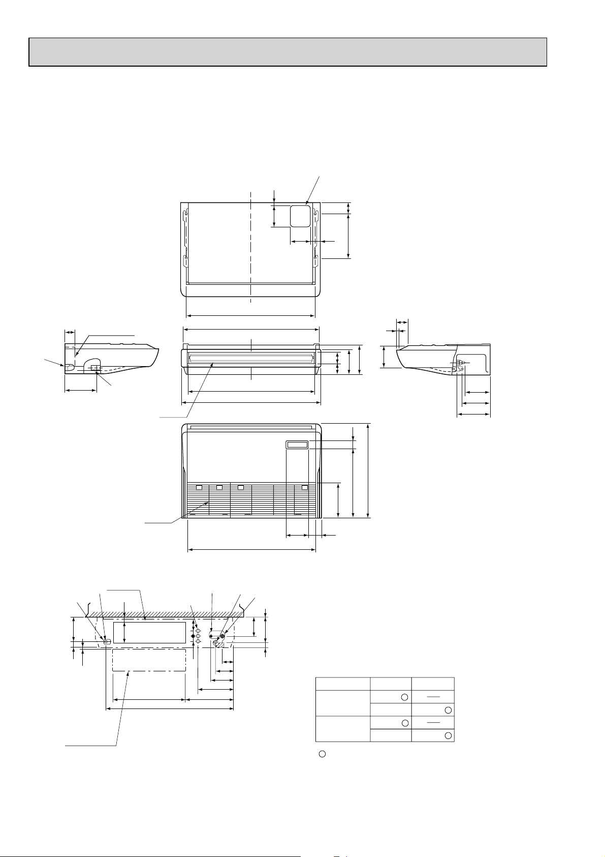
PCA-RP50GA
17
150
NOTES:
1. Use M10 or W3/8 screws for anchor bolt.
2. When optional drain pump is installed, always provide
upward piping for refrigerant piping.
80
140
70
320
Unit : mm
70
Electrical box
226
179
42
6~7
When electrical
box is pulled
down
Electrical box
32
161
Air outlet
Air intake
[Front view]
Ceiling
525
928
933 (suspension bolt pitch)
79
38
38
86
138
171
263
352
1000
983
904
918
131
46 175 1
85
15
76
81
254
161 90
1 Drainage pipe connection (26mm I.D.)
2 Drainage pipe connection (for the left arrangement)
3 Knockout hole for left drain-piping arrangement
4 Refrigerant-pipe connection (gas pipe side/flared connection)
5 Refrigerant-pipe connection (liquid pipe side/flared connection)
6 Knockout hole for upper drain pipe arrangement
7 Knockout hole for left drain pipe arrangement
8 Knockout hole for wiring arrangement
180
157
210
182 liquid
201 gas
241 (Drainage)
680
506 56
Use the current nuts meeting the pipe size of the outdoor unit.
Available pipe size
P50
:9.52
:15.88
LIQUID SIDE
GAS SIDE
RP50
:6.35
:9.52
:12.7
:15.88
: Factory flare nut attachment to the heat-exchanger.
40
Page 41

PCA-RP50GA2
PCA-RP60GA
PCA-RP70GA
NOTES:
1. Use M10 or W3/8 screws for anchor bolt.
2. When optional drain pump is installed, always provide
upward piping for refrigerant piping.
17
150
140
70
320 80
Unit : mm
179
42
70
226
When electrical
box is pulled
down
Electrical box
6~7
Air outlet
Air intake
Electrical box
32
161
[ Front view ]
Ceiling
525
1235
1240 (suspension bolt pitch)
1290
1214
1310
1228
3879
38
138
171
263
416
131
86
175 1
46
85
15
157
210
180
81 76
182
(liquid)
201
(5/8F gas)
241
(Drainage)
680
506 56
254
161 90
1 Drainage pipe connection (26mm I.D.)
2 Drainage pipe connection (for the left arrangement)
3 Knockout hole for left drain-piping arrangement
4 Refrigerant-pipe connection (gas pipe side/flared connection)
5 Refrigerant-pipe connection (liquid pipe side/flared connection)
6 Knockout hole for upper drain pipe arrangement
7 Knockout hole for left drain pipe arrangement
8 Knockout hole for wiring arrangement
Use the current nuts meeting the pipe size of the outdoor unit.
Available pipe size
RP71,P60,P71
:9.52
:15.88
LIQUID SIDE
GAS SIDE
RP50
:6.35
:9.52
:12.7
:15.88
RP60
:6.35
:9.52
:15.88
41
: Factory flare nut attachment to the heat-exchanger.
Page 42

PCA-RP100GA
NOTES:
1. Use M10 or W3/8 screws for anchor bolt.
2. When optional drain pump is installed, always provide
upward piping for refrigerant piping.
18
150
70
140
320 80
Unit : mm
70
42 239
When electrical
box is pulled
down
229
Electrical box
6~7
Air intake
Electrical box
93
160
525
Air outlet
[ Front view ]
1235
Ceiling
1240 (suspension bolt pitch)
1214
1310
1228
687
38 140
38
86
138
171
263
192
87
16
217
270
207
81 96
680
506 56
254
161 90
1 Drainage pipe connection (26mm I.D.)
2 Drainage pipe connection (for the left arrangement)
3 Knockout hole for left drain-piping arrangement
4 Refrigerant-pipe connection (gas pipe side/flared connection)
5 Refrigerant-pipe connection (liquid pipe side/flared connection)
1
236
45
6 Knockout hole for upper drain pipe arrangement
7 Knockout hole for left drain pipe arrangement
8 Knockout hole for wiring arrangement
Use the current nuts meeting the pipe size of the outdoor unit.
Available pipe size
LIQUID SIDE
RP100
:9.52
P100
:9.52
GAS SIDE
:15.88
:19.05
:19.05
:Factory flare nut attachment to the heat-exchanger.
182
198
245
(3/8F liquid)
(5/8F, 3/4F gas)
(Drainage)
42
Page 43

PCA-RP125GA
PCA-RP140GA
NOTES:
1. Use M10 or W3/8 screws for anchor bolt.
2. When optional drain pump is installed, always provide
upward piping for refrigerant piping.
18
150
140
70
320 80
Unit : mm
42 239
70
Electrical box
229
When electrical
box is pulled
down
Air outlet
Air intake
Electrical box
6~7
93
160
525
[ Front view ]
Ceiling
1545
1547(suspension bolt pitch)
1524
1620
1535
38 140
38
687
86
138
171
263
87
16
217
270
207
81 96
680
506 56
254
161 90
1 Drainage pipe connection (26mm I.D.)
2 Drainage pipe connection (for the left arrangement)
3 Knockout hole for left drain-piping arrangement
4 Refrigerant-pipe connection (gas pipe side/flared connection)
5 Refrigerant-pipe connection (liquid pipe side/flared connection)
1
6 Knockout hole for upper drain pipe arrangement
7 Knockout hole for left drain pipe arrangement
192
8 Knockout hole for wiring arrangement
236
45
Use the current nuts meeting the pipe size of the outdoor unit.
Available pipe size
RP125,140
P125,140
LIQUID SIDE
:9.52
:9.52
GAS SIDE
:15.88
:19.05
:19.05
:Factory flare nut attachment to the heat-exchanger.
182
198
245
(3/8F liquid)
(5/8F, 3/4F gas)
(Drainage)
43
Page 44

Ceiling
Less than
Less than
or more
Less than
or more
or more
300
<Suspension bolt pitch>
model:PAC-SG38KF-E (12pcs.)
Filter element for the exchange
1.Use M10 or W3/8 screw for anchor bolt.
NOTES.
Option parts:duct flange( : 200). model: PAC-SF28OF-E(1 pc.)
Knockout hole for wiring arrangement : 2- : 27
(12 2 )
<Filter contour dimension>
16
handle
100
100113 6
366
480
176
318
650
<Flexible hose(accessory)>
Terminal block box
9
Terminal block(remote controller)
8
Terminal block(indoor/outdoor connecting line)
78
Inspection port
(pipe sensor)
The half bottom of FAN CASING
can be separated.
Adjustable part
288
360
<Air outlet>
<Suspension bolt pitch>
<Air outlet>
<Air intake>
<Air intake>
Filter (3-pieces)
Terminal block box
5
2
1
4
3
Knockout hole for upper refrigerant-pipe arrangement
6
9
2
1
Flexible hose(accessory) Drainage pipe connection(26mm I.D.)
2
Refrigerant-pipe connection(gas pipe side/flared connection : 5/8F)
38
105
85
90°
Electrical box
Rear wall
500
250
2 ~ 3
(Gap to ceiling)
Allowing clearances
<gas>
<liquid>
7
Knockout hole (duct for fresh air intake): 2- : 200
6
5
1
3
4
Knockout hole for behind refrigerant-piping arrangement
Refrigerant-pipe connection(liquid pipe side/flared connection : 3/8F)
Suspension bolt
130
210
45
165
120
1224
118 0
75
1136
986
1098
70
243
254
175
197
110
21
130 15
258 110 102
320 80
90
14018
75
70~90
650
13
289
75
280
495
43
295
:222
:200
PCA-RP71HA
Unit : mm
44
Page 45

Ceiling
Less than
Less than
Less than
or more
or more
or more
4
3156728
9
Refrigerant-pipe connection(gas pipe side/flared connection : 5/8F, 3/4F)
Knockout hole (duct for fresh air intake) : 2- : 200
Option parts:duct flange( : 200). model: PAC-SF28OF-E(1 pc.)
Flexible hose(accessory) Drainage pipe connection(26mm I.D.)
Terminal block(indoor/outdoor connecting line)
Terminal block(remote controller)
Refrigerant-pipe connection(liquid pipe side/flared connection : 3/8F)
Knockout hole for behind refrigerant-piping arrangement
Knockout hole for upper refrigerant-pipe arrangement
Knockout hole for wiring arrangement : 2- : 27
Allowing clearances
Rear wall
(Gap to ceiling)
NOTES.
1.Use M10 or W3/8 screw for anchor bolt.
Use the current nuts meeting the pipe size
of the outdoor unit.
model:PAC-SG38KF-E (12pcs.)
Filter element for the exchange
<Suspension bolt pitch>
(122)246
handle
16
<Flexible hose(accessory)>
Terminal block box
78
<Filter contour dimension>
Inspection port
(pipe sensor)
The half bottom of
FAN CASING
can be separated.
Adjustable part
288
360
<Air outlet>
<Suspension bolt pitch>
<Air outlet>
<Air intake>
<Air intake>
Filter (4-pieces)
Terminal block box
5
2
1
4
3
6
9
2
1
176
38 210
105
8545
165
:222
:200
440440298
130
90°
650
300
1001520100
Electrical box
500
250
2~3
<gas>
<liquid>
Suspension bolt
70
243
254
175
197
110
21
130 15
258
1482
110 102
1370 75
1608
320 801564
1520
90 120
14018
75
70~90
650
13
289
75
280
495
43
295
: 9.52
RP125
: 15.88
: 19.05
Available pipe size
LIQUID SIDE
GAS SIDE
: Factory flare nut attachment to the heat-exchanger
PCA-RP125HA
Unit : mm
45
Page 46

PSA-RP71GA
Knockout hole
for under-piping
Unit : mm
5 or more
300 or more
2
1
Front 1,000 or more
1. Service access allows for
insertion of screw driver.
100 or more 100 or more
40 66
55 143
Liquid pipe :9.52(3/8F)
Gas pipe :15.88(5/8F)
2. Adjustable
186
Drain pipe
590
480
110
132
Knockout hole
for branch duct
Front side
218
VIEW "A"
95
Knockout hole for
under-piping(120 70 oval)
130
100
100
Rear side
20
160
90
Knockout hole
for bottom fixing
175
270
250
40
50260
Metal fixture
against overturning
277
130130
95
Electrical parts box
46122
Terminal block for
indoor/outdoor
connection.
Terminal block for
heater power supply
766
(Only PSH-P•GAH)
1900
608
105
47
Knockout hole for piping and wiring
767
714 123
(140 80 oval)
20
115
50
180
235
70
216
A
Knockout hole for
wiring.:27
(Provided on both sides)
Knockout hole for refrigerant and drainage.
90 60 oval (Provided on both sides)
240
Rear side
10
3838
15
111
10
125
340
Front side
370
520
260
240
2010
controller
130 71
46
82730
530
600
Page 47

PSA-RP100GA
PSA-RP125GA
PSA-RP140GA
300 or more
1
5 or more
2
Unit : mm
Front 1,000 or more
Knockout hole
for under-piping
Front side
218
VIEW "A"
95
Knockout hole for
under-piping(120 70 oval)
: 9.52
P100,125,140—: 19.05
: 9.52
RP100,125,140
: 15.88
: 19.05
: Factory flare nut attachment to
LIQUID SIDE
120
GAS SIDE
277
Use the current nuts meeting the pipe size
of the outdoor unit.
Available pipe size
77
201
120
Rear side
20
140
Knockout hole
for bottom fixing
255
the heat-exchanger
Terminal block for
indoor/outdoor
100 or more 100 or more
40 66
Liquid pipe :9.52(3/8F)
95
Electrical parts box
46122
connection.
Terminal block for
heater power supply
(Only PSH-P•GAH)
1. Service access allows for
insertion of screw driver.
2. Adjustable
261
Drain pipe
Gas pipe :15.88(5/8F)
:19.05(3/4F)
47
767
714 123
590
480
110
105
Knockout hole for piping and wiring
(140 80 oval)
20
115
50
Knockout hole for
wiring.:27 (Provided on both sides)
A
132
Knockout hole
for branch duct
240
Rear side
10
3838
15
111
260
350
330
40
130
100
125
340
370
Front side
10
50260
Metal fixture
against overturning
520
260
240
2010
130130
controller
766
130 71
1900
608
82730
216
315
70
Knockout hole for refrigerant and drainage.
90 60 oval (Provided on both sides)
530
600
47
Page 48
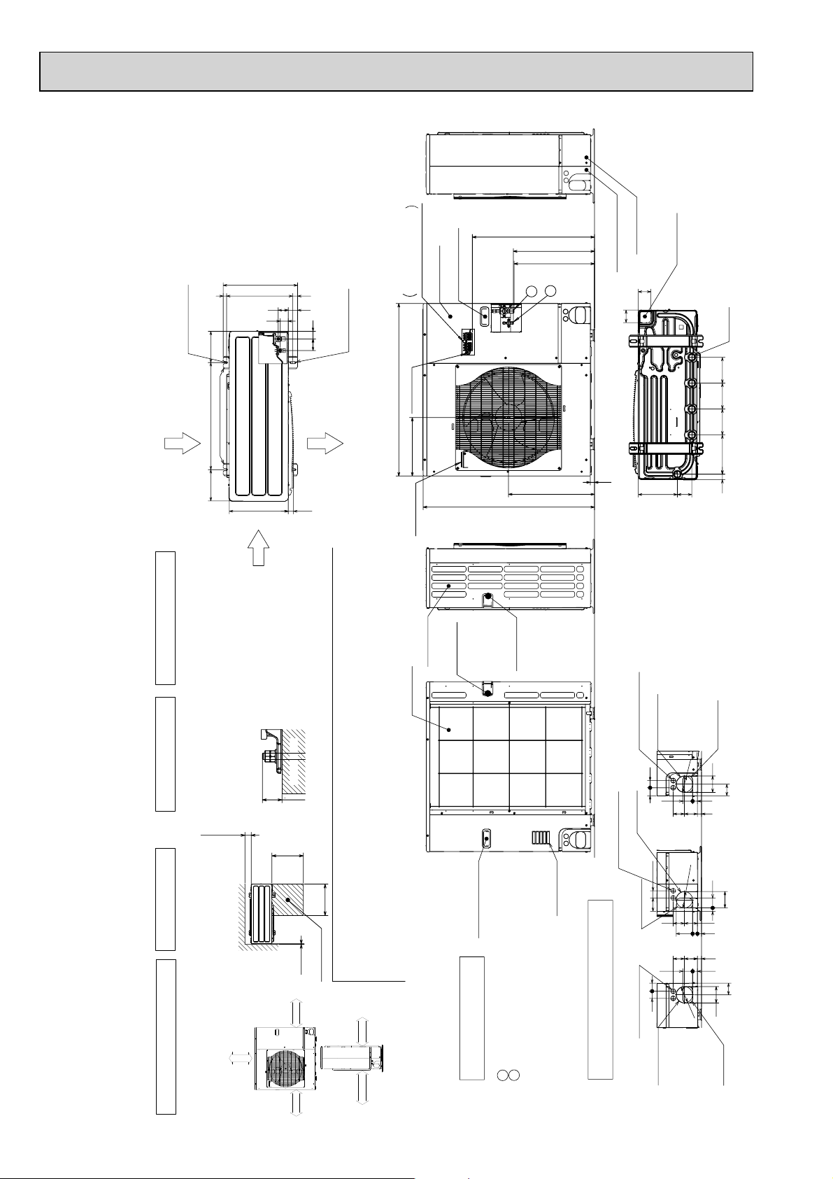
OUTDOOR UNIT
PUH-P71VHA PUH-P71YHA
PUH-P100VHA PUH-P100YHA
PU-P71VHA PU-P71YHA
PU-P100VHA PU-P100YHA
Unit : mm
(19)37028
2-U Shaped notched holes
(Foundation Bolt M10)
175600175
Rear Air Intake
Installation Feet
Side Air Intake
417
330
670
*1 447
*1 443
Left···Power supply wiring
Right···Indoor/Outdoor wiring
Terminal Connections
56
53
45
66 42
2-12%36 oval holes
(Foundation Bolt M10)
950
Earth terminal
Air Discharge
322
30
Handle for moving
Service panel
Handle for moving
943
1
2
473
Rear piping cover
Front piping cover
71
71
23
Bottom piping hole
(Knockout)
81 219
Drain hole
(5-W33)
145
14522030 145
4 PIPING-WIRING DIRECTIONS
Piping and wiring connections
can be made from 4 directions:
front, right, rear and below.
FOUNDATION
3 FOUNDATION BOLTS2 SERVICE SPACE
Please secure the unit firmly
with 4 foundation (M10) bolts.
(Bolts and washers must be
<Foundation bolt height>
purchased locally.)
Over100
30
Less than
500
Over
500
Over
Dimensions of space needed
for service access are
shown in the below diagram.
Over10
Service space
over 10mm
over 100mm
FREE
1 FREE SPACE (Around the unit)
The diagram below shows a
basic example.
Explanation of particular details is
given in the installation manuals etc.
over 10mm
over 500mm
Rear Air Intake
Side Air Intake
Handle for moving
Handle for moving
Handle for moving
Example of Notes
1
2
···Refrigerant GAS pipe connection (FLARE)W15.88(5/8F)
···Refrigerant LIQUID pipe connection (FLARE)W 9.52(3/8F)
+1 ···Indication of STOP VALVE connection location.
Air Intake
Power supply wiring hole
(2-W27Knockout)
Rear trunking hole
(Knockout)
4045
Right trunking hole
(Knockout)
Power supply wiring hole
(2-W27Knockout)
4075
Right piping hole
(Knockout)
45
40
Power supply wiring hole
(2-W27Knockout)
Piping Knockout Hole Details
Front trunking hole
(Knockout)
92
W
92
W
7323 63
92
W
Rear piping hole
(Knockout)
92
65
27 55
23 73 63
92
19 55
73 63
23 27 92
27 55
65
92
Front piping hole
(Knockout)
48
Page 49
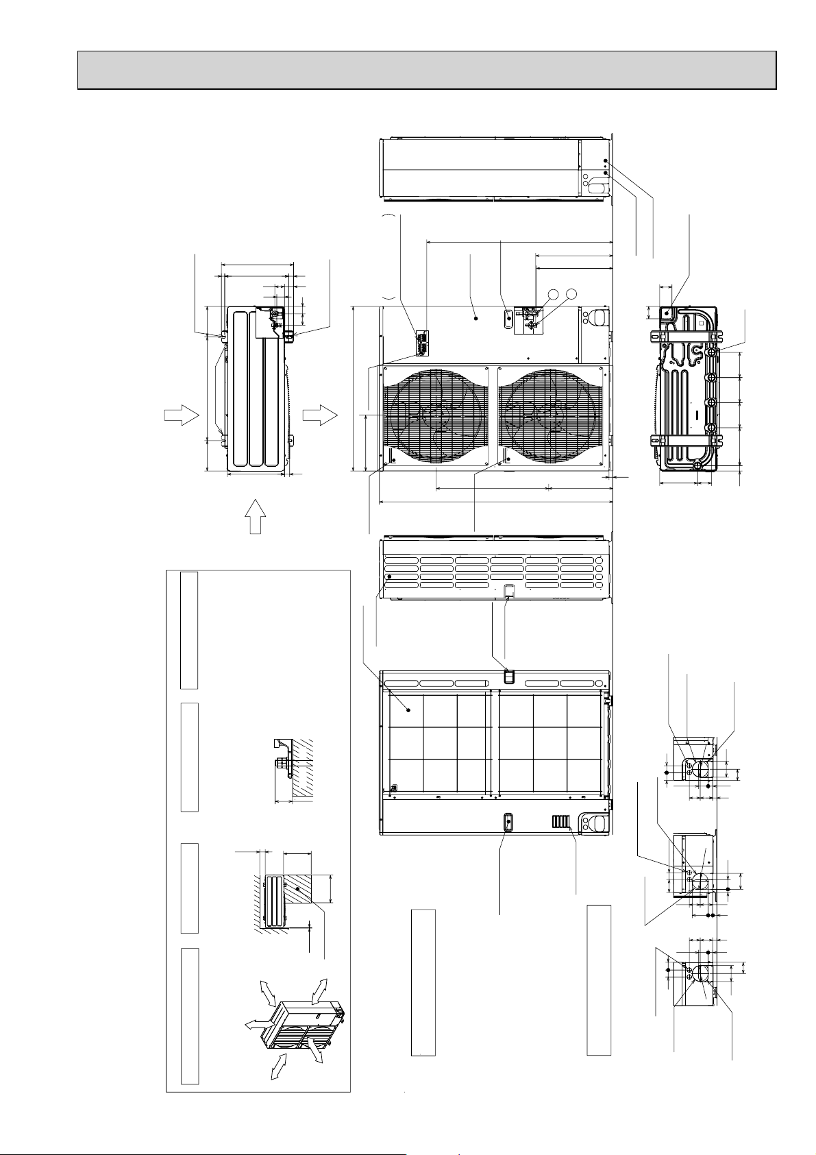
PUH-P125YHA
Less than
Over
Over
Over
Over
Handle for moving
Side Air Intake
Front piping cover
Rear piping cover
Air intake
Rear Air Intake
Handle for moving
Handle for moving
Terminal connection
Left···Power supply wiring
Right···Indoor/Outdoor wiring
Earth terminal
Service panel
Handle for moving
1
2
The diagram below shows a
basic example.
Explanation of particular details is
given in the installation manuals etc.
Dimensions of space needed
for service access are
shown in the below diagram.
<Foundation bolt height>
Please secure the unit firmly
with 4 foundation (M10) bolts.
(Bolts and washers must be
purchased locally.)
Air Discharge
Rear Air Intake
Side Air Intake
···Refrigerant GAS pipe connection (FLARE)W15.88(5/8F)
···Refrigerant LIQUID pipe connection (FLARE)W 9.52(3/8F)
+1 ···Indication of STOP VALVE connection location.
Example of Notes
Piping Knockout Hole Details
1 FREE SPACE (Around the unit)
2 SERVICE SPACE
3 FOUNDATION BOLTS
4 PIPING-WIRING DIRECTIONS
Piping and wiring connections
can be made from 4 directions:
front, right, rear and below.
30
FOUNDATION
150
500
500
10
Service space
600175 175
330
417
42
66
53 56
45
(19)28 370
2-U Shaped notched holes
(Foundation Bolt M10)
2-12 × 36 Oval holes
(Foundation Bolt M10)
Installation Feet
30
45 40
65
92
27 55
23
73 63
Rear piping hole
(Knockout)
Rear trunking hole
(Knockout)
Power supply wiring hole
(2-
W
27Knockout)
W
92
19 55
92
75 40
73 63
23
27 92
Right piping hole
(Knockout)
Right trunking hole
(Knockout)
Power supply wiring hole
(2-
W
27Knockout)
W
92
92
65
4540
27 55
23
73 63
Front piping hole
(Knockout)
Front trunking hole
(Knockout)
Power supply wiring hole
(2-
W
27Knockout)
W
92
14514522030 145
81 219
71
71
Bottom piping hole
(Knockout)
Drain hole
(5-W33)
1350
23
950
1076
+1 447
+1 443
371 635
322
Handle for moving
Over 10mm
Over 10mm
Over 150mm
Ove
r 1000mm
FREE
Handle
for
moving
PUH-P140YHA
PU-P125YHA
PU-P140YHA
Unit : mm
49
Page 50
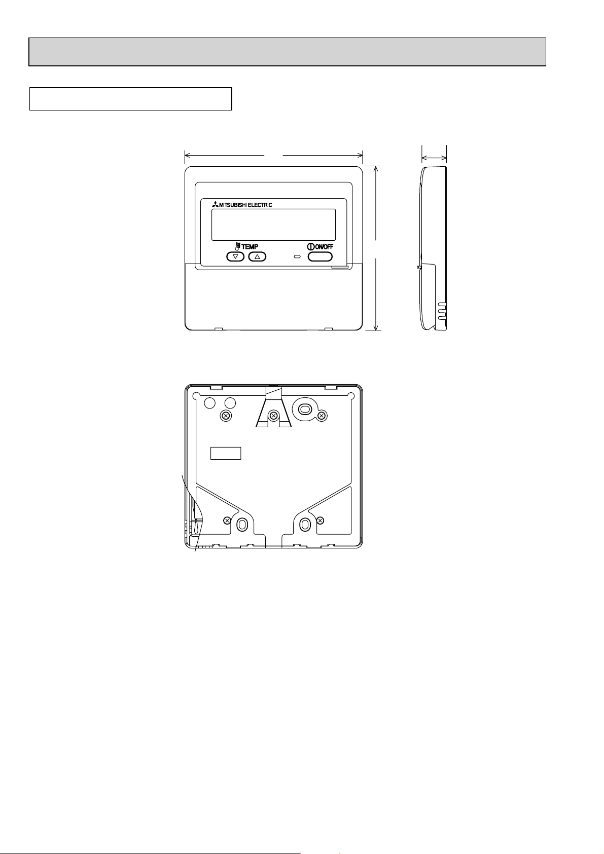
WIRED REMOTE CONTROLLER
Unit : mm
130
19.5
120
50
Page 51
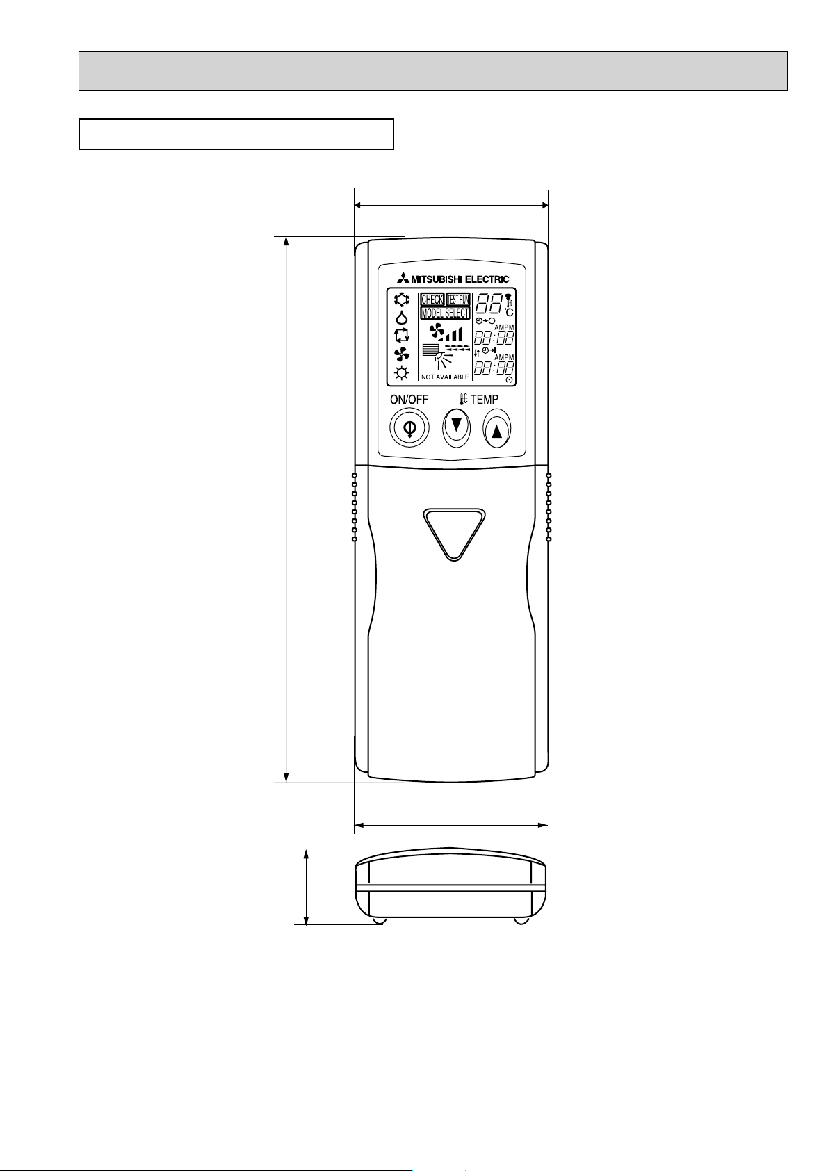
WIRELESS REMOTE CONTROLLER
Unit : mm
58
159.3
55
19
51
Page 52
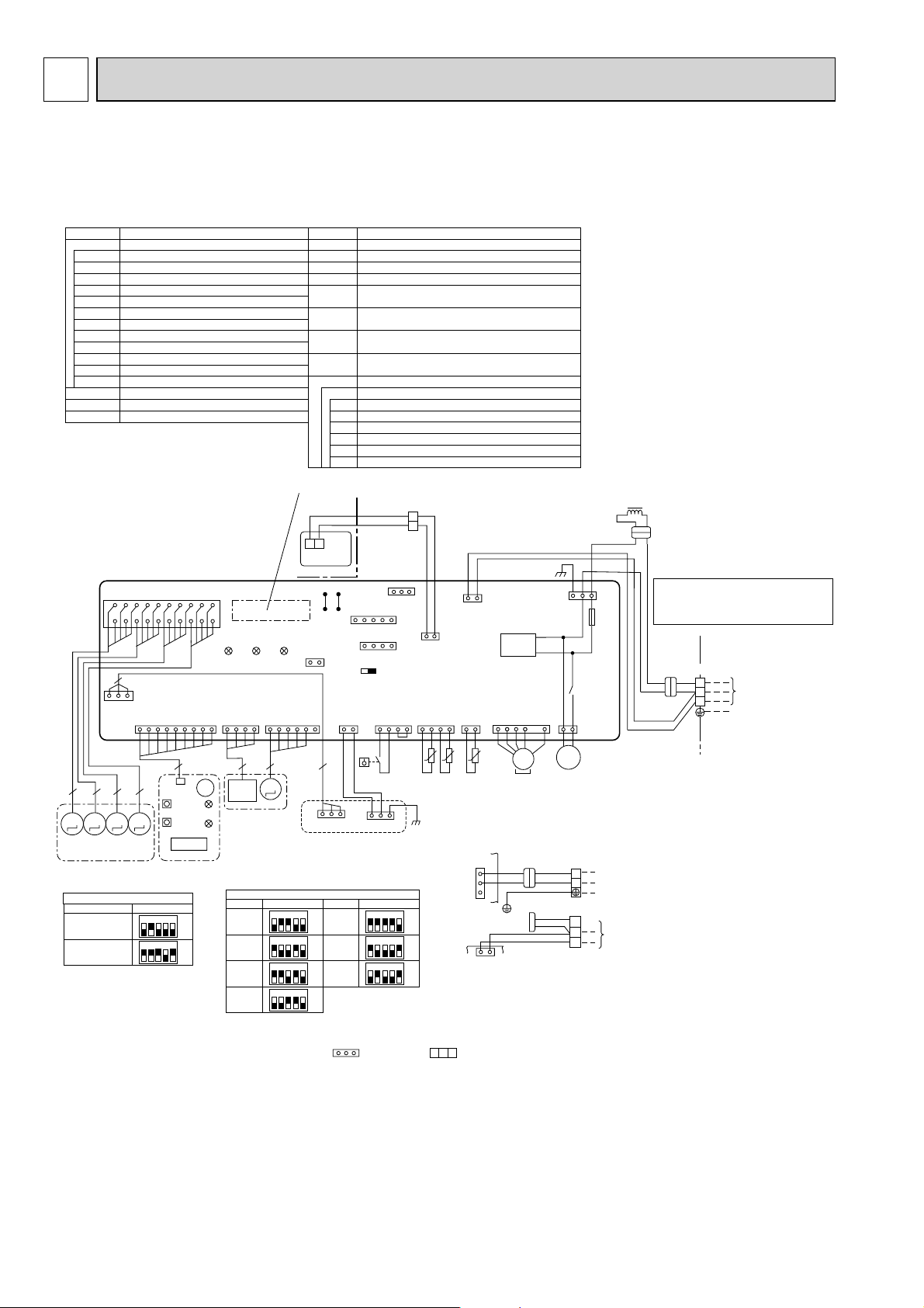
4
WIRING DIAGRAM
4-1. INDOOR UNIT
PLA-RP35BA PLA-RP50BA PLA-RP60BA PLA-RP71BA
PLA-RP100BA PLARP125BA PLA-RP140BA PLA-RP140BA2
[LEGEND]
SYMBOL SYMBOLNAME NAME
I.B
DCL
DP
FS
MMMM
<Table 1> SW1 (MODEL SELECTION)
PLA-RP·BA
PLA-RP140BA2
INDOOR CONTROLLER BOARD
CN2L
CONNECTOR (LOSSNAY)
CN32
CONNECTOR (REMOTE SWITCH)
CONNECTOR (HA TERMINAL-A)
CN41
CN51
CONNECTOR (CENTRALLY CONTROL)
FUSE
FUSE (T6.3AL250V)
LED1
POWER SUPPLY (I.B)
LED2
POWER SUPPLY (R.B)
LED3
TRANSMISSION (INDOOR-OUTDOOR)
SW1
SWITCH (MODEL SELECTION) +See table 1
SW2
SWITCH (CAPACITY CODE) +See table 2
SWE
CONNECTOR (EMERGENCY OPERATION)
X1
RELAY (DRAIN PUMP)
REACTOR
DRAIN PUMP
DRAIN FLOAT SWITCH
MF
MV
TB2
TB4
TB5,TB6
TH1
TH2
TH5
OPTION PART
W.B
BZ
LED1
LED2
RU
SW1
SW2
FAN MOTOR
VANE MOTOR
TERMINAL BLOCK (Indoor unit Power (option))
TERMINAL BLOCK (
TERMINAL BLOCK (REMOTE CONTROLLER
TRANSMISSION LINE)
ROOM TEMP. THERMISTOR
(0 / 15k, 25 / 5. 4k DETECT)
PIPE TEMP. THERMISTOR/LIQUID
(0 / 15k, 25 / 5. 4k DETECT)
COND. / EVA. TEMP. THERMISTOR
(0 / 15k, 25 / 5. 4k DETECT)
PCB FOR WIRELESS REMOTE CONTROLLER
BUZZER
LED (OPERATION INDICATION : GREEN)
LED (PREPARATION FOR HEATING : ORANGE)
RECEIVING UNIT
EMERGENCY OPERATION (HEAT / DOWN)
EMERGENCY OPERATION (COOL / UP)
INDOOR/OUTDOOR CONNECTING LINE
)
Refer to tables 1 and 2
YLW
FUSE
CNP
(BLU)
POWER SUPPLY
~(1PHASE)
230V 50Hz
TO OUTDOOR UNIT
DCL
Please set the voltage using the
remote controller.
For the setting method,please refer to
the indoor unit Installation Manual.
TB4
YLW
YLW
ORN
BRN
ORN
S1
S2
S3
ORN
TB5
2
1
2
1
TB6
I.B
VAN E
CNV(
20
18
19
3
1 3
AUTO GRILLE
CN3G
(BLK)
MVMVMV
GRILLE
MODELS
Notes:
1. SymboIs used in wiring diagram above are, : Connector, : Terminal (block).
2. Indoor and outdoor connecting wires have poIarities, make sure to match terminal numbers (S1, S2, S3) for correct wirings.
3. Since the outdoor side electric wiring may change, be sure to check the outdoor unit electric wiring diagram for servicing.
4. This diagram shows the wiring of indoor and outdoor connecting wires (specification of 230V), adopting superimposed system for
power and signal.
+1: If indoor and outdoor units have separate power supplies, refer to Fig.1.
+2: For power supply system of this unit, refer to the caution label located near this diagram.
WHT)
WIRELESS
CN90
(WHT)
114169
9
CNB
5555
SW1
SW2
MV
SW1
SETTING
12345
12345
ON
OFF
ON
OFF
RU
1234567891011121314151617
LED3 LED2 LED1
I-SEE SENSOR
CN4Y
(WHT)
4 5
I-SEE
BZ
SENSOR
LED2
I-SEE SENSOR
CORNER PANEL
(OPTION PART)
LED1
W.B
<Table 2> SW2 (CAPACITY CODE)
CAPACITY
35
50
60
71
The black square () indicates a switch position.
R.B
SW2SW1
CN2L
21
I-SEE
SENSOR MOTOR
CN6Y
(RED)
3
M
U.B
MT
AUTOMATIC FILTER ELEVATION PANEL
(OPTION PART)
SW2
SETTING
12345
ON
OFF
12345
ON
OFF
12345
ON
OFF
12345
ON
OFF
TRANSMISSION
WIRES
DC12V
J42J41
CN32
(WHT)
CN51(WHT)
Pair No.
51
CN41(WHT)
41
SWE
ON OFF
AUTO GRILLE
POWER
CNAC
(WHT)
31
CN3G
CAPACITY
100
125
140
113
FLOAT SW
CN4F
(WHT)
FS
13135
CN3A
SETTING
12345
12345
12345
21
REMOCON
CN22
(BLU)
LIQUID/PIPE
CN44
(WHT)
4
14
t° t° t°
TH2 TH5 TH1
ON
OFF
ON
OFF
ON
OFF
OUTDOOR
135
CN01
DC280V
FAN
CNMF
(WHT)
MS
3~
MF
(BLK)
31
DP
X1
D.U.M
M
1~
3
1
INDOOR/OUTDOOR
COMMUNICATION
CN3C
(BLU)
RECTIFICATION
INTAKE
CN20
(RED)
741
21
+ Be sure to turn off the source power
and then disconnect fan motor connector.
(Failure to do so will cause trouble in Fan motor)
+1(Fig. 1)
CN01
I.B
I.B
(BLK)
5
3
1
CN3C
(BLU)
31
YLW
ORN
INDOOR/OUTDOOR
COMMUNICATION
GRN/YLW
YLW
ORN
ORN
BRN
RED
BLU
TB2
TB4
S1
S2
S3
L
N
TO OUTDOOR
UNIT
52
Page 53
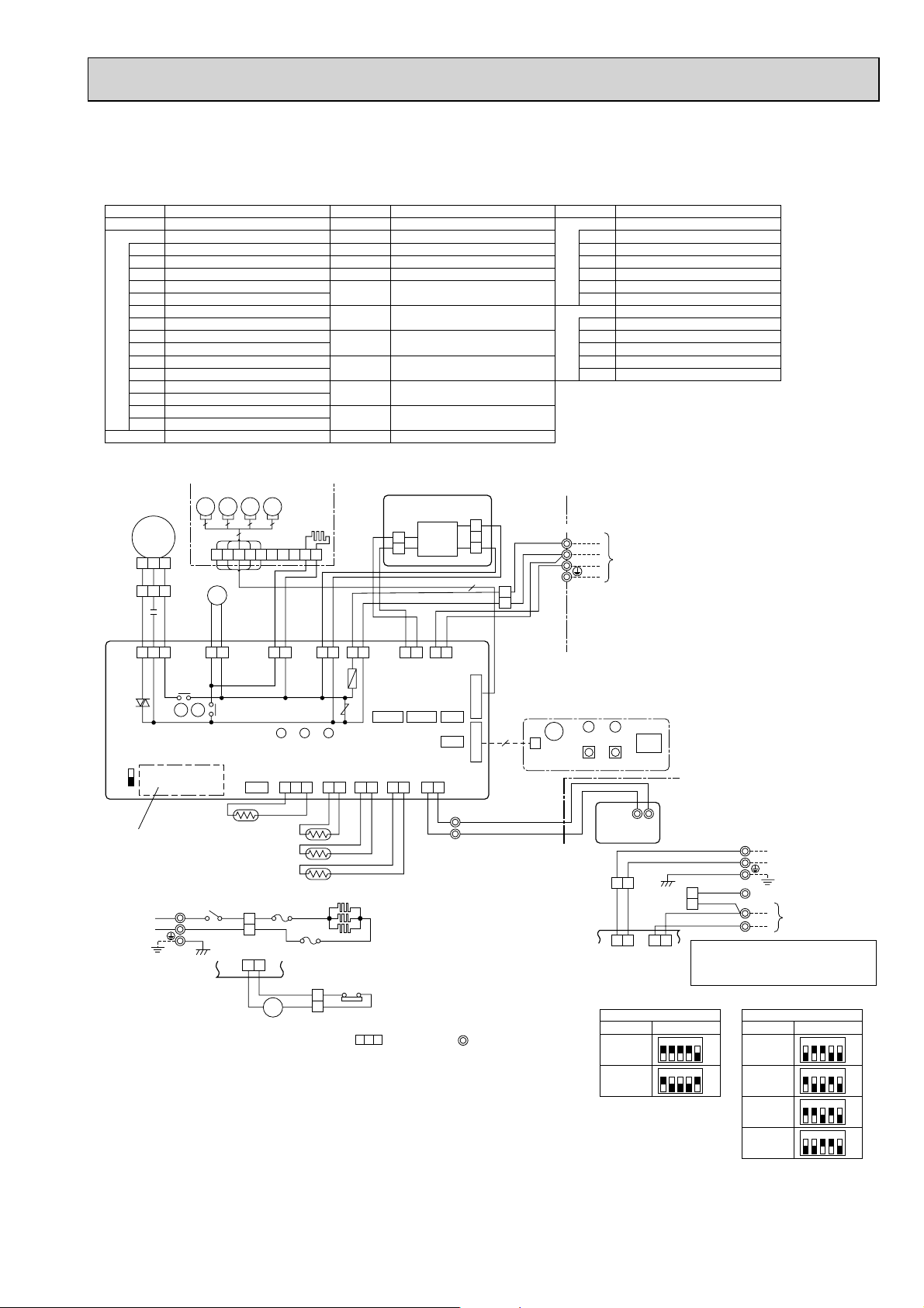
PLA-RP35AA PLA-RP50AA PLA-RP60AA PLA-RP71AA
[LEGEND]
SYMBOL NAME SYMBOL NAME SYMBOL NAME
P. B
C CAPACITOR(FAN MOTOR)
INDOOR POWER BOARD
INDOOR CONTROLLER BOARDI.B
FUSE(T6.3AL250V)FUSE
VAR IST ORZNR
FAN CONTROL ELEMENTBCR
CN2L
CONNECTOR(LOSSNAY)
CONNECTOR(REMOTE SWITCH)
CN32
CN41 CONNECTOR(HA TERMINAL-A)
CN51 CONNECTOR(CENTRALLY CONTROL)
LED1 POWER SUPPLY(I.B)
LED2 POWER SUPPLY(I.B)
LED3 TRANSMISSION(INDOOR-OUTDOOR)
X1 RELAY(DRAIN PUMP)
X4 RELAY(FAN MOTOR)
SW1
SWITCH(MODEL SELECTION)+See table 1
SWITCH(
SW2
SWE
CAPACITY CODE
CONNECTOR(EMERGENCY OPERATION)
)+See table 2
MF FAN MOTOR
MV VANE MOTOR
H2 DEW PREVENTION HEATER
DP DRAIN PUMP
DS DRAIN SENSOR
TB2
TB4 TERMINAL BLOCK (INDOOR/
TB5, TB6 TERMINAL BLOCK(REMOTE
TH1 ROOM TEMP.THERMISTOR
TH2 PIPE TEMP.THERMISTOR/LIQUID
TH5 COND./EVA. TEMP. THERMISTOR
R.B
TERMINAL BLOCK (HEATER)+PLH-P.AAH
models only or option for PLA-RP.AA models.
OUTDOOR CONNECTING LINE)
CONTROLLER TRANSMISSION LINE)
(0/15k,25/5.4k DETECT)
(0/15k,25/5.4k DETECT)
(0/15k,25/5.4k DETECT)
WIRED REMOTE CONTROLLER BOARD
W.B
WIRELESS REMOTE CONTROLLER BOARD
RU RECEIVING UNIT
BZ BUZZER
LED1 LED(RUN INDICATOR)
LED2 LED(HOT ADJUST)
SW1 SWITCH(HEATING ON/OFF)
SW2 SWITCH(COOLING ON/OFF)
HEATER
FS1 THERMAL FUSE(72, 16A)
FS2 THERMAL FUSE(104, 16A)
H1 HEATER
26H HEATER THERMAL SWITCH
88H HEATER CONTACTOR
MF
321
321
C
I.B
RED
WHT
BLK
FAN
(WHT)
531
BCR
SWE
SW2 SW1
ON
OFF
Refer to tables 1
and 2.
D.U.M
CNP
(BLU)
X4
5MV5MV5
DP
YLW
X1X4
YLW
D.HEATER
31
CNC(RED)
X1
GRILLE
MV5MV
5
76321 84
HEATER
CN24
(YLW)
DS
H2
9 5
10
YLW
LED3 LED2 LED1
RED
POWER
CNDK
(RED)
CN31
(WHT)
321 21 21
WHT
INTAKE
CN20
(RED)
FUSE
YLW
31 31 31 31
D.SENSOR
TH1
TH2
YLW
ZNR
LIQUID
ORN
POWER
CND
(ORN)
CN21
(WHT)
CN2S
(WHT)
2
13.1V
1
BLK
WHT
21
POWER
INDOOR/OUTDOOR
CN2D
(WHT)
CN41CN51 CN2L
REMOCON
PIPE
CN22
CN29
(BLU)
(BLK)
21
BLU
DC
ORN
BRN
COMMUNICATION
CN3C
(BLU)
CN32
WIRELESS
21
TB5
BLU
2
1
P. B
CNSK
(RED)
3
2
1
YLW
ORN
ORN
BRN
5
VAN E
CN6V
(GRN)
W.B
9
CNB
CN90
(WHT)
TRANSMISSION WIRES
DC12V
BZ
TB4
S1
S2
S3
1 (Fig.1)
LED2
SW1 SW2
TH3
[PLH-P.AAH models only]
POWER SUPPLY
~(1PHASE)
230V 50Hz
TB2
L
RED RED RED
N
BLU
GRN/YLW
88H
I.B
1
WHT
2
HEATER CN24
(YLW)
1
2
YLW
YLW
88H
FS1
FS2
H1
26H
WHT
6
WHTGRY
5
Notes:
1. SymboIs used in wiring diagram above are, : Connector, : Terminal (block).
2. Indoor and outdoor connecting wires have poIarities, make sure to match terminal
numbers (S1, S2, S3) for correct wirings.
3. Since the outdoor side electric wiring may change, be sure to check the outdoor unit
electric wiring diagram for servicing.
4. This diagram shows the wiring of indoor and outdoor connecting wires (specification
of 230V), adopting superimposed system for power and signal.
+1: If indoor and outdoor units have separate power supplies, refer to Fig.1.
+2: For power supply system of this unit, refer to the caution label located near this diagram.
TO OUTDOOR UNIT
LED1
TB6
YLW
ORN
I.B
POWER
INDOOR/OUTDOOR
CND
(ORN)
Table 1
MODELS
PLA-RP· AA
PLH-P·AAH
RU
R.B
21
GRN/YLW
3131
Please set the voltage using the
COMMUNICATION
CN3C
(BLU)
remote controller.
For the setting method. please refer to
the indoor unit Installation Manual.
SW1
Manufacture/Service
1 2 3 4 5
ON
OFF
1 2 3 4 5
ON
OFF
RED
BLU
YLW
ORN
ORN
BRN
TB2
TB4
Table 2
L
POWER SUPPLY
N
~(1PHASE)
230V 50Hz
S1
S2
TO OUTDOOR UNIT
S3
MODELS
PLA-RP35AA
PLH-P35AAH
PLA-RP50AA
PLH-P50AAH
PLA-RP60AA
PLH-P60AAH
PLA-RP71AA
PLH-P71AAH
SW2
Manufacture/Service
1 2 3 4 5
ON
OFF
1 2 3 4 5
ON
OFF
1 2 3 4 5
ON
OFF
1 2 3 4 5
ON
OFF
5353
Page 54
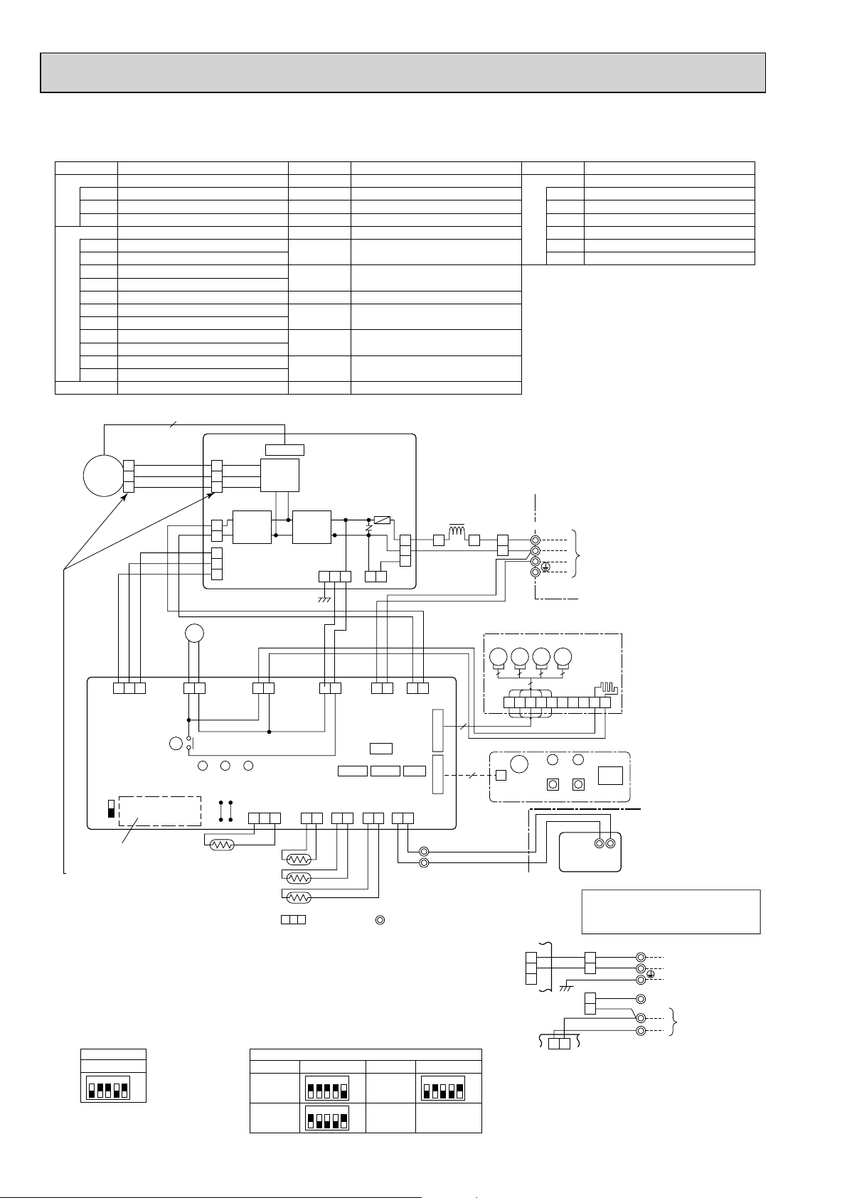
PLA-RP100AA2 PLA-RP125AA2 PLA-RP140AA2
[LEGEND]
SYMBOL NAME SYMBOL NAME SYMBOL NAME
P. B
MF FAN MOTOR
INDOOR POWER BOARD
FUSE(T5AL250V)
FUSE
ZNR VARISTOR
IPM POWER MODULE
INDOOR CONTROLLER BOARDI.B
CN2L CONNECTOR(LOSSNAY)
CN32
CONNECTOR(REMOTE SWITCH)
CN41 CONNECTOR(HA TERMINAL-A)
CN51 CONNECTOR(CENTRALLY CONTROL)
LED1 POWER SUPPLY(I.B)
LED2 POWER SUPPLY(I.B)
LED3 TRANSMISSION(INDOOR-OUTDOOR)
X1 RELAY(DRAIN PUMP)
SW1
SWITCH(MODEL SELECTION)+See table 1
CAPACITY CODE
SWITCH(
SW2
SWE
CONNECTOR(EMERGENCY OPERATION)
5
3
MF
2
1
BLK
WHT
RED
)+See table 2
CN4
(WHT)
5
3
1
CN2S
(WHT)
2
1
3
FAN
2
CN2
(GRN)
1
IPM
TRANS
MV VANE MOTOR
H2 DEW PREVENTION HEATER
DP DRAIN PUMP
DS DRAIN SENSOR
TB2
TERMINAL BLOCK (Indoor unit Power (option))
TB4 TERMINAL BLOCK
(INDOOR/OUTDOOR CONNECTING LINE)
TB5, TB6 TERMINAL BLOCK(REMOTE
CONTROLLER TRANSMISSION LINE)
DCL REACTOR
TH1 ROOM TEMP.THERMISTOR
(0/15k,25/5.4k DETECT)
TH2 PIPE TEMP.THERMISTOR/LIQUID
(0/15k,25/5.4k DETECT)
TH5 COND./EVA. TEMP. THERMISTOR
(0/15k,25/5.4k DETECT)
R.B
POSITION DETECTION
RECTIFIER
WIRED REMOTE CONTROLLER BOARD
11
CN01
(BLK)
5
3
1
CN02
(GRN)
P. B
SENSOR INPUT
CN3
(WHT)
ZNR
CN03
(BLU)
2
53
FUSE
DCL
YLWYLW
ORN
W.B
WIRELESS REMOTE CONTROLLER BOARD
RU RECEIVING UNIT
BZ BUZZER
LED1 LED(RUN INDICATOR)
LED2 LED(HOT ADJUST)
SW1 SWITCH(HEATING ON/OFF)
SW2 SWITCH(COOLING ON/OFF)
TB4
S1
YLW
ORN
S2
ORN
BRN
TO
OUTDOOR
S3
UNIT
DP
I.B
ON
OFF
Refer to tables 1
and 2.
+Be sure to turn off the source power
and then disconnect fan motor connector.
(Failure to do so will cause trouble in Fan motor)
Notes:
1. SymboIs used in wiring diagram above are, : Connector, : Terminal (block).
2. Indoor and outdoor connecting wires have poIarities, make sure to match terminal
numbers (S1, S2, S3) for correct wirings.
3. Since the outdoor side electric wiring may change, be sure to check the outdoor unit
electric wiring diagram for servicing.
4. This diagram shows the wiring of indoor and outdoor connecting wires (specification
of 230V), adopting superimposed system for power and signal.
+1: If indoor and outdoor units have separate power supplies, refer to Fig.1.
+2: For power supply system of this unit, refer to the caution label located near this diagram.
(Table 1) SW1 (MODEL SELECTION)
Manufacture/Service
1 2 3 4 5
FAN
SWE
SW1
BLK
WHT
PNK
CN33
(GRN)
SW2 SW1
ON
OFF
D.U.M
CNP
(BLU)
X1
YLW
3121 3
X1
LED3
YLW
D.HEATER
LED2 LED1
Pair No.
J41
YLW
INTAKE
CN20
(RED)
ORN
POWER
CND
(ORN)
LIQUID
CN21
(WHT)
PIPE
CN29
(BLK)
CNC
(RED)
J42
YLW
YLW
31 331 31
D.SENSOR
CN31
(WHT)
21 21 21
DS
TH1
TH2
TH5
(Table 2) SW2 (CAPACITY CORD)
MODELS
PLA-RP100AA2 PLA-RP140AA2
PLA-RP125AA2
Manufacture/Service
1 2 3 4 5
1 2 3 4 5
ON
OFF
ON
OFF
SW2
INDOOR/OUTDOOR
ORN
BRN
COMMUNICATION
CN3C
(BLU)
CN32
CN41CN51 CN2L
REMOCON
CN22
(BLU)
21
BLU
MODELS
BLK
WHT
VAN E
21
CN6V
POWER
(GRN)
CN2D
(WHT)
21
BLU
2
1
5
9
WIRELESS
CN90
(WHT)
TB5
TRANSMISSION WIRES
DC12V
Manufacture/Service
1 2 3 4 5
ON
OFF
5MV5MV5
W.B
CNB
+1 (Fig.1)
GRILLE
MV5MV
5
76321 84
BZ
LED2
LED1
SW1 SW2
CN01
(BLK)
P. B
YLW
5
ORN
3
1
I.B
31
INDOOR/OUTDOOR
COMMUNICATION
CN3C
(BLU)
H2
9 5
10
GRILLE
RU
R.B
21
TB6
Please set the voltage using the
remote controller.
For the setting method. please refer to
the indoor unit Installation Manual.
TB2
L
RED
BLU
GRN/YLW
YLW
ORN
ORN
BRN
TB4
POWER SUPPLY
N
~(1PHASE)
230V 50Hz
S1
S2
TO OUTDOOR UNIT
S3
54
Page 55
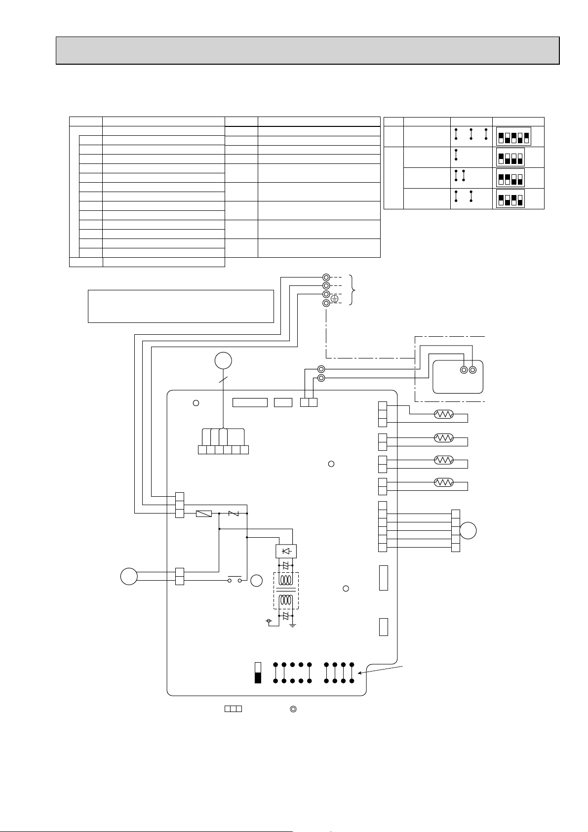
PMH-P25BA PMH-P35BA PMH-P50BA
[LEGEND]
SYMBOL
I.B INDOOR CONTROLLER BOARD
CN2L CONNECTOR(LOSSNAY)
CN32 CONNECTOR(REMOTE SWITCH)
CN41 CONNECTOR(HA TERMINAL-A)
FUSE FUSE(6.3A , 250V)
LED1 POWER SUPPLY(I.B)
LED2 POWER SUPPLY(R.B)
LED3 TRANSMISSION(INDOOR-OUTDOOR)
SW1 JUMPER WIRE(MODEL SELECTION)
SW2 JUMPER WIRE(CAPACITY CODE)
SWE SWITCH(EMERGENCY OPERATION)
T TRANSFORMER
X1 RELAY(DRAIN PUMP)
ZNR VARISTOR
R.B
WIRED REMOTE CONTROLLER BOARD
NAME
Please set the voltage using the remote controller.
For the setting method, please refer to the indoor
unit Installation Manual.
I.B
LED1 CN90 CN32
6 5 4 3 251
BRN
5
ORN
3
YLW
1
FUSE
POWER
CN03
(RED)
SYMBOL
DP DRAIN PUMP
DS DRAIN SENSOR
MF FAN MOTOR
MV
TB4
TB5,TB6 TERMINAL BLOCK
TH1 ROOM TEMP. THERMISTOR
TH2 PIPE TEMP. THERMISTOR / LIQUID
TH5 COND, / EVA. TEMP, THERMISTOR
VANE MOTOR
TERMINAL BLOCK
(INDOOR / OUTDOOR CONNECTING LINE)
(REMOTE CONTROL TRANSMISSION LINE)
(0/15k25/5.4k DETECT)
(0/15k25/5.4k DETECT)
(0/15k25/5.4k DETECT)
MF
NAME
BLU
BLU
TB5
TB4
2
1
2 1
REMOTE
CONTROLLER
CN22
(BLU)
FAN
(WHT)
ZNR
LED2
<Fig.1>
SW1
PMH-P25/35/50BA
PMH-P25BA
SW2
PMH-P35BA
PMH-P50BA
S1
S2
TO OUTDOOR UNIT
S3
TRANSMISSION WIRES DC12V
BLK
CN31
(WHT)
INTAKE
CN20
(RED)
LIQUID
CN21
(WHT)
PIPE
CN29
(BLK)
VAN E
CN6V
(WHT)
3
2
BLK
1
BLK
2
BLK
1
BLK
2
BLK
1
BLK
2
BLK
1
6
BRN
5
RED
4
ORN
3
YLW
2
GRN
1
D.SENSOR
MODELS
Manufacture
J11 J12 J13 J14 J15
J21 J22 J23 J24
J21 J22 J23 J24
J21 J22 J23 J24
R.B
12
TB6
DS
TH1
TH2
TH5
1
2
3
MV
4
5
Service board
12345
1234
ON
OFF
1234
ON
OFF
1234
ON
OFF
ON
OFF
DP
BLU
BLU
1
3
D.U.M
CNP
(YLW)
X1
ON
OFF
T
X1
LED3
J24
J23
J22
J21
J15
J14
J13
J12
J11
SW1SWE
SW2
CN41
CN2L
See Fig. 1
Notes:
1. SymboIs used in wiring diagram above are, : Connector, : Terminal (block).
2. Indoor and outdoor connecting wires have poIarities, make sure to match terminal numbers (S1, S2, S3) for correct wirings.
3. Since the outdoor side electric wiring may change, be sure to check the outdoor unit electric wiring diagram for servicing.
4. This diagram shows the wiring of indoor and outdoor connecting wires (specification of 230V), adopting superimposed system for
power and signal.
55
Page 56
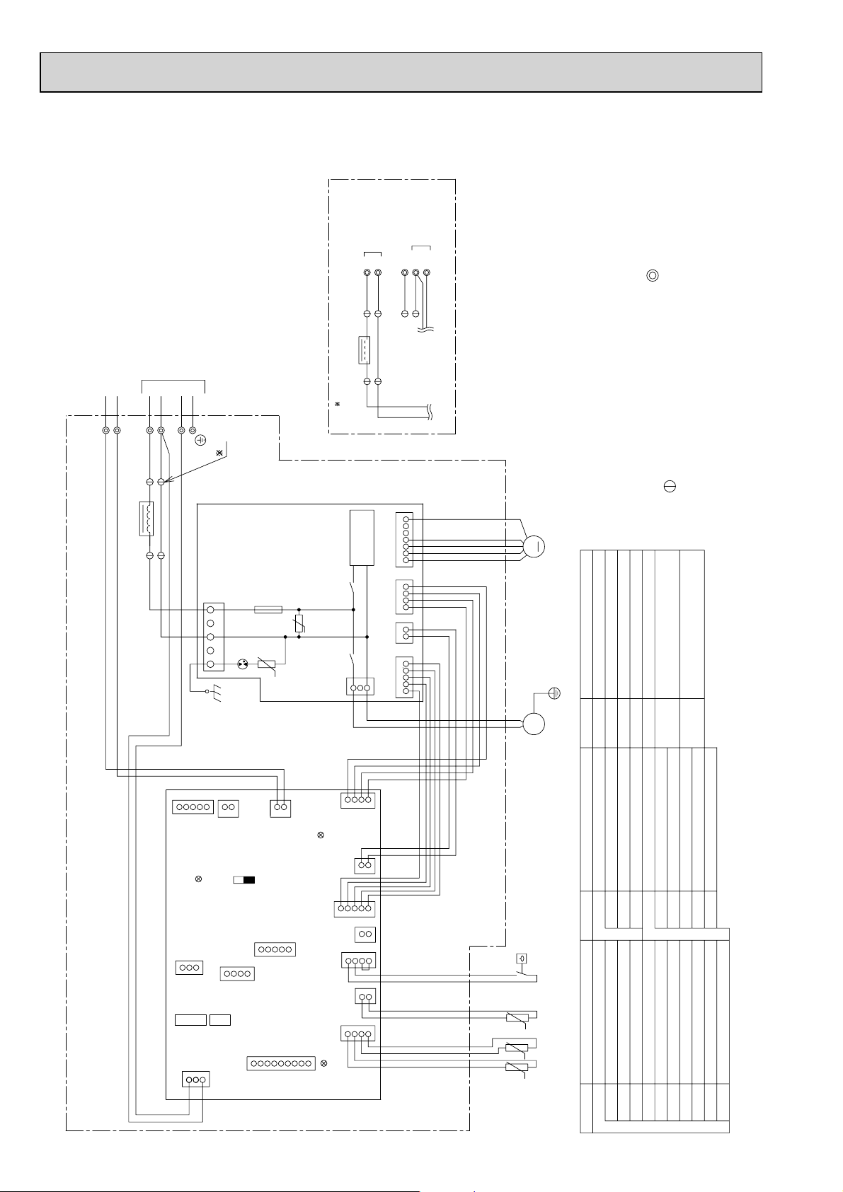
PEAD-RP35JA(L) PEAD-RP50JA(L) PEAD-RP60JA(L) PEAD-RP71JA(L)
PEAD-RP100JA(L) PEAD-RP125JA(L) PEAD-RP140JA(L)
TO OUTDOOR
POWER SUPPLY
~(1PHASE)
N
L
1
2
UNIT
220~240V 50Hz
S1S2S3
1
2
TB15
INSIDE SECTION OF CONTROL BOX
TO MA REMOTE
CONTROLLER
TB4
1
2
ACL
TO OUTDOOR UNIT
S1S2S3
1
2
1
2
ACL
(IN CASE OF CONNECT THE REPLACEMENT WIRING)
1
< A>
2
TO CN3C
TO CND
A
connector.
make wiring matching terminal numbers (S1,S2,S3).
*1. Drain pump and float switch: only for PEAD-JA model
check the outdoor unit electric wiring for servicing.
3. Symbols used in wiring diagram above are, terminal block,
2. Indoor and outdoor connecting wires are made with polarities,
P. B .
CND
(Red)
351
DSA
F01
U
ZNR01
ZNR02
456
CNMF
71
DC280~340V
Rectifier circuit
(Blue)
3
4
CNXA1
21123
CNXC1
5
32
CNXB1
14
X10
U
X01
1
CNP
(Blue)
M
*1
M
1~
NOTE: 1. Since the outdoor side electric wiring may change be sure to
Fan motor
NAME
(Indoor/outdoor connecting line)
AC reactor (Power factor improvement)
Float switch
Terminal block
Terminal block
(Remote controller transmission line)
FS
TB4
ACL
TB15
SYMBOL
Drain pump
Intake air temp. Thermistor
Cond./eva.temp. Thermistor
Pipe temp. Thermistor/liquid
TH5
TH2
TH1
I.B.
(Red)
CN105
LED2
CN32
SW1
(Blue)
CN3C
1
3
SW2
CN2A
(Black)
ON
CN41
SWE
OFF
2
1
CN22
(Blue)
CN51
CN90
(Blue)
CNXA2
LED1
CNXB2
CN4F
CN44
LED3
2
1
(Red)
1
(Red)
1
243
CNXC2
2
1
3
5
4
CN2L
4
2
3
2
1
CN20
213
4
56
NAME
Switch (for mode selection)
Switch (for capacity code)
Connector (emergency operation)
Fuse AC250V 6.3AConnector (Centrally control)
Indoor controller board
SW1
SWE
SW2
SYMBOL
I.B.
Arrester
Varistor
ZNR01, 02
F01
Aux. relay
X01
DSA
Aux. relay
X10
Power supply board
P. B .
*1
FS
TH1
t°
t° t°
TH5
TH2
NAME
Connector (0-10V Analog input)
Connector (Lossnay)
Indoor controller board
CN2L
CN2A
SYMBOL
I.B.
SYMBOL EXPLANATION
Connector (Remote switch)
Connector (Wireless)
Connector (IT terminal)
Connector (HA terminal-A)
CN41
CN32
CN51
CN90
CN105
LED(Power supply)
LED(Transmission indoor-outdoor)
LED(Remote controller supply)
LED3
LED1
LED2
Page 57
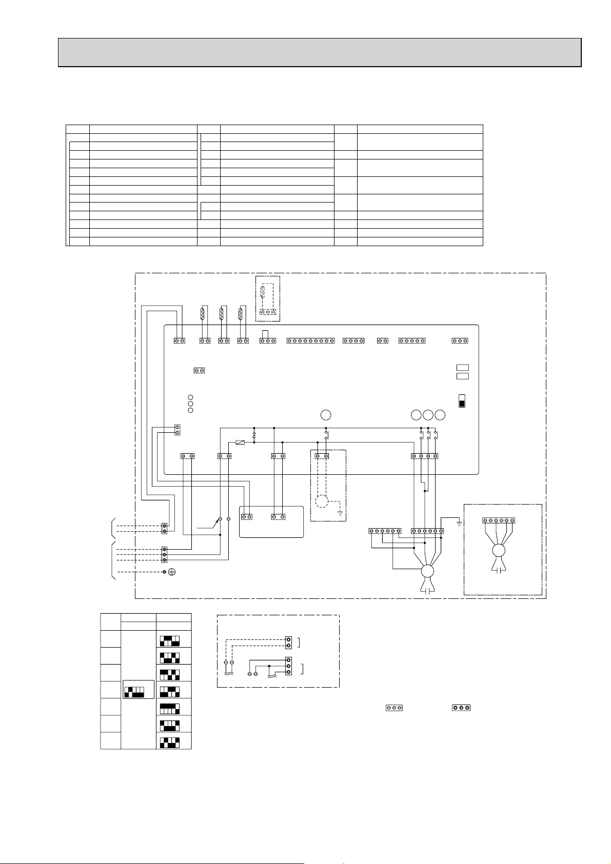
PEAD-RP35EA2 PEAD-RP50EA PEAD-RP60EA PEAD-RP71EA
PEAD-RP100EA2 PEAD-RP125EA PEAD-RP140EA
SYMBOL
I.B.
INDOOR CONTROLLER BOARD
FUSE
FUSE(T6.3AL250V)
ZNR
VAR IST OR
CN2L
CONNECTOR(LOSSNAY)
NAME
CN24 CONNECTOR(HEATER)
CN32
CONNECTOR(REMOTE SWITCH)
CN41
CONNECTOR(HA TERMINAL-A)
CONNECTOR(CENTRALLY CONTROL)
CN51
CONNECTOR(WIRELESS) DP
CN90
POWER SUPPLY(I.B.)
LED1
LED2
POWER SUPPLY(REMOTE CONTROLLER)
LED3
TRANSMISSION(INDOOR•OUTDOOR)
SW1
SWITCH(MODEL SELECTION)
TO MA-REMOTE
CONTROLLER
DC8.7-13V
TO OUTDOOR UNIT
WHT
BLK
SWITCH(CAPACITY CODE)
SW2
SWITCH(EMERGENCY OPERATION)
SWE
RELAY(DRAIN PUMP)
X1
RELAY(FAN MOTOR)
X4
RELAY(FAN MOTOR)
X5
RELAY(FAN MOTOR)
X6
P. B .
INDOOR POWER BOARD
DRAIN PUMP
(OPTIONAL PARTS)
DRAIN PUMP
DRAIN SENSOR
DS
C
CAPACITOR(FAN MOTOR)
MF
FAN MOTOR
SYMBOLSYMBOL
TERMINAL BLOCKTB4
(INDOOR/OUTDOOR CONNECTING LINE)
TB5
TERMINAL BLOCK(REMOTE CONTROLLER)
TH1
INTAKE AIR TEMP. THERMISTOR
(0 /15k,25/5.4k DETECT)
TH2
PIPE TEMP. THERMISTOR/LIQUID
(0 /15k,25/5.4k DETECT)
TH5
COND./EVA. TEMP. THERMISTOR
(0 /15k,25/5.4k DETECT)
NAMENAME
INSIDE SECTION OF CONTROL BOX
DS
TH5TH2TH1
1
B
B
L
L
U
U
1
1
2
2
CN20 CN21 CN29
CN22
(RED)
(BLU)
1
2
CN2L
(RED)
LED1
LED2
LED3
2
CN2D
1
(WHT)
(BLU)
CN3C
(ORN)
CND
31
B
O
R
R
N
N
B
TB5
L
B
U
2
1
TB4
S3
BRN
ORN
S2
S1
YLW
+A
L
U
1
(WHT)
31
O
R
W
N
2
1
2
(BLK)
FUSE
Y
L
W
H
T
1
3
CN31
123456789 432145321
12
2
3
CN31
(WHT)
CN90
(WHT)
CN41
(WHT)
12
CN24
(YLW)
CN51
(WHT)
X1
X5
ZNR
(RED)
CNDK
W
B
H
L
T
K
B
L
K
2
1
CN2S
(WHT)
W
H
T
B
L
K
31
P. B .
CNSK
(RED)
X1
(BLU)
CNP
1331
DP
Optional parts
<PEAD-RP35•50•60EA, 35EA2>
External static
pressure 70Pa
(RED)
X4
W
P
P
H
N
N
T
K
K
643521
I.B.
321
CN32
(WHT)
SW1
SW2
SWE
ON
OFF
X6X5X4
X6
1375
(WHT)
FAN
B
L
K
<PEAD-RP35•50•60EA, 35EA2>
External static
pressure 30Pa
<PEAD-RP71•100•125•140EA, 100EA2>
External static pressure 70Pa
643521
(WHT)
Optional parts
643521
(RED)
MF
MF
C
<PEAD-RP71•100•125•140EA, 100EA2>
External static
pressure 130Pa
C
MODELS
35EA(2)
50EA
60EA
71EA
100EA(2)
125EA
140EA
SW1
Model selection
switch
54321
ON
OFF
SW2
Capacity cord
switch
12345
12345
12345
12345
12345
12345
12345
ON
OFF
ON
OFF
ON
OFF
ON
OFF
ON
OFF
ON
OFF
ON
OFF
<+A>
(IN CASE OF CONNECT
THE REPLACEMENT WIRING)
POWER SUPPLY
L
~(1PHASE)
N
12
TO CND
21
12
TO CN3C
230V 50Hz
S1
S2
TO OUTDOOR
S3
UNIT
Notes:
1. SymboIs used in wiring diagram above are, : Connector, : Terminal (block).
2. Indoor and outdoor connecting wires have poIarities, make sure to match terminal
numbers (S1, S2, S3) for correct wirings.
3. Since the outdoor side electric wiring may change, be sure to check the outdoor unit
electric wiring diagram for servicing.
4. This diagram shows the wiring of indoor and outdoor connecting wires (specification
of 230V), adopting superimposed system for power and signal.
+1: If indoor and outdoor units have separate power supplies, refer to +A.
+2: For power supply system of this unit, refer to the caution label located near this diagram.
57
Page 58

PEAD-RP60GA PEAD-RP71GA PEAD-RP100GA
SYMBOL
I.B.
INDOOR CONTROLLER BOARD
FUSE
FUSE(T6.3AL250V)
ZNR
VAR ISTO R
CONNECTOR(LOSSNAY)
CN2L
CN24 CONNECTOR(HEATER)
CN32
CONNECTOR(REMOTE SWITCH)
CN41
CONNECTOR(HA TERMINAL-A)
CN51
CONNECTOR(CENTRALLY CONTROL)
CONNECTOR(WIRELESS)
CN90
POWER SUPPLY(I.B.)
LED1
LED2
POWER SUPPLY(REMOTE CONTROLLER)
LED3
TRANSMISSION(INDOOR•OUTDOOR)
NAME
WHT
BLK
B
L
U
CN22
(BLU)
LED1
LED2
LED3
2
1
SW1
SW2
SWE
X1
X4
X5
X6
P. B .
C
MF
TB4
TH1
B
L
U
1
1
2
2
CN2D
(WHT)
(BLU)
CN3C
31
O
R
N
B
R
N
1
CN2L
(RED)
2
CN20
CN21 CN29
(RED)
2
(BLK)
(WHT)
FUSE
CND CNDK
31
Y
O
L
R
W
N
SWITCH(MODEL SELECTION)
SWITCH(CAPACITY CODE)
SWITCH(EMERGENCY OPERATION)
RELAY(DRAIN PUMP)
RELAY(FAN MOTOR)
RELAY(FAN MOTOR)
RELAY(FAN MOTOR)
INDOOR POWER BOARD
CAPACITOR(FAN MOTOR)
FAN MOTOR
TERMINAL BLOCK
(INDOOR/OUTDOOR CONNECTING LINE)
INSIDE SECTION OF CONTROL BOX
TH5TH2
121
12
3
ZNR
CN31
(WHT)
W
H
T
123456789
CN90
(WHT)
B
L
K
X1
321
4
CN41
(WHT)
X1
(BLU)(RED)(ORN)
CNP
1331
SYMBOLSYMBOL
1
CN24
(YLW)
TERMINAL BLOCK(REMOTE CONTROLLER)
TB5
TH1
INTAKE AIR TEMP.THERMISTOR
(0 /15k,25/5.4k DETECT)
NAMENAME
TH2
PIPE TEMP. THERMISTOR/LIQUID
(0 /15k,25/5.4k DETECT)
TH5
COND./EVA. TEMP. THERMISTOR
(0 /15k,25/5.4k DETECT)
I.B.
2
CN51
(WHT)
G
R
Y
54321
X5
X4
5
Y
Y
L
L
W
W
21
3
CN32
(WHT)
SW1
SW2
SWE
ON
OFF
X6X5X4
X6
137
(WHT)
FAN
B
L
K
B
W
W
TO MA-REMOTE
CONTROLLER
DC8.7-13V
TO OUTDOOR UNIT
<+A>
12
21
TO CND
B
TB5
L
B
U
2
L
1
U
TB4
S3
BRN
ORN
S2
S1
YLW
(IN CASE OF CONNECT
THE REPLACEMENT WIRING)
12
TO CN3C
POWER SUPPLY
L
~(1PHASE)
N
230V 50Hz
S1
S2
TO OUTDOOR
S3
UNIT
B
L
H
K
T
2
2 1
+A
1
(WHT)
CN2S
L
H
K
T
P. B .
13
CNSK
(RED)
O
B
B
R
L
L
G
K
U
MF
C
54321
ON
OFF
SW2SW1
Capacity cord
switch
12345
12345
12345
ON
OFF
ON
OFF
ON
OFF
MODELS
60GA
71GA
100GA
Model selection
switch
*External static pressure
*
CONNECTOR COLOR
643521
(WHT)
(FACTORY SHIPMENT)
BLU
WHT
RED
5Pa
35Pa
10Pa
50Pa
70Pa50Pa
Notes:
1. SymboIs used in wiring diagram above are, : Connector, : Terminal (block).
2. Indoor and outdoor connecting wires have poIarities, make sure to match terminal numbers (S1, S2, S3) for correct wirings.
3. Since the outdoor side electric wiring may change, be sure to check the outdoor unit electric wiring diagram for servicing.
4. This diagram shows the wiring of indoor and outdoor connecting wires (specification of 230V), adopting superimposed system for
power and signal.
+1: If indoor and outdoor units have separate power supplies, refer to +A.
+2: For power supply system of this unit, refer to the caution label located near this diagram.
240V230V220V
20Pa
60Pa
75Pa
58
Page 59

PKA-RP35HAL PKA-RP50HAL
[Explanation of symbols]
Symbol
I.B Indoor controller board
CN2L Connector (LOSSNAY)
CN32 Connector (Remote switch)
CN41 Connector (HA terminal-A)
CN51 Connector (Centrally control)
CN90 Connector (Remote operation adapter)
FUSE FUSE(T3.15AL250V)
LED1 Power supply (I.B)
LED2 Power supply (R.B)
LED3 Transmission (Indoor-outdoor)
SW1 Switch (Model selection)
SW2
Switch (Capacity code)
Connector (Emergency operation)
SWE
X1 Relay (Drain pump (option))
Drain pump (option) power supply
CNP
(Drain pump (option))
CN4F Drain float switch (Drain pump (option))
R.B
Wired remote controller (option)
TB6
Terminal block (Remote controller transmission line)
I.B
SWE
ON
OFF
Refer to
tables
1and 2
CN151
(WHT)
11
M
Notes:
1. SymboIs used in wiring diagram above are, : Connector, : Terminal (block).
2. Indoor and outdoor connecting wires have poIarities, make sure to match terminal
numbers (S1, S2, S3) for correct wirings.
3. Since the outdoor side electric wiring may change, be sure to check the outdoor unit
electric wiring diagram for servicing.
4. This diagram shows the wiring of indoor and outdoor connecting wires. (specification of
230V), adopting superimposed system for power and signal.
1: If indoor and outdoor units have separate power supplies, refer to Fig. 1.
2: For power supply system of this unit, refer to the caution label located near this diagram.
Name
See table 1
See table 2
T11 DB1
LED1
LED3
LED2
CN90
(WHT)
2
11 1 5
CN2L
CN41
(RED)
(WHT)
CN20
CN44
(RED)
(WHT)
141425
t
tt
TH1 TH2 TH5
1319
4
When attaching
drain pump(option),
remove the jumper
connector CN4F
and fit the drain
float switch (FS).
CN32
(WHT)
CN51
(WHT)
CN4F
(WHT)
MS
3~
CNMF
1
(WHT)
X1
Symbol
M Vane motor
MS Fan motor
S.W
Switch board
SWE2 Emergency operation
TB2 Terminal block(Indoor unit Power (option))
TB4 Terminal block (Indoor/outdoor connecting line)
Terminal block (Remote controller transmission line(option))
TB5
TH1 Room temp. Thermistor
(0
TH2
TH5
W.B PCB for wireless remote controller
LED1 LED (Operation indication : Green)
LED2 LED (Preparation for heating: Orange)
REC1 Receiving unit
DCL REACTOR
DP
DP
FS
6
FUSE
CN01
(BLK)
3
1
CNP(BLU)
3
CN3C
(BLU)
1
LDSWE(A)
(BLU)
CNRU
(WHT)
1
CN22
(BLU)
2
When attaching drain
pump (option)
FLOAT SW
CN4F
(WHT)
/15k, 25 /5.4k Detect)
Pipe temp. Thermistor/liquid
/15k, 25 /5.4k Detect)
(0
Cond./eva. temp. Thermistor
/15k, 25 /5.4k Detect)
(0
DRAIN PUMP (OPTION)
DRAIN FLOAT SWITCH (OPTION)
DCL
1
3
ORN
5
BLK
DP
M
1~
W.B
6
14
FS
YLW YLWYLW
ORN
BRN
LD101(B)
LED1
Name
ORN
2
RU
REC1
LED2
TB4
S1
S2
S3
S.W
LDSWE(B)
1
3
5
TO
OUTDOOR
UNIT
SWE2
CN01
(BLK)
<Table 1>
SW1
(MODEL SELECTION)
SETTING
12345
<Table 2>
SW2 (CAPACITY CODE)
MODELS
RP35
RP50
The black square () indicates a switch position.
BLU
1
BLU
2
TB5
(OPTION PARTS)
1(Fig. 1)
I.B
YLW
ORN
GRN/YLW
I.B
INDOOR/OUTDOOR
3
1
COMMUNICATION
CN3C(BLU)
RED
BLU
YLW
ORN
ORN
BRN
R.B
TB6
TB2
TB4
S1
S2
S3
1
2
L
N
ON
OFF
SETTING
12345
12345
POWER SUPPLY
~(1PHASE)
230V 50Hz
ON
OFF
ON
OFF
TO OUTDOOR
UNIT
59
Page 60

PKA-RP60KAL PKA-RP71KAL PKA-RP100KAL
[LEGEND]
I.B
CN2L
CN32
CN41
CN51
CN90
FUSE
LED1
LED2
LED3
SW1
SW2
SWE
X1
CNP
CN4F
R.B
TB6
Indoor controller board
Connector (LOSSNAY)
Connector (Remote switch)
Connector (HA terminal-A)
Connector (Centrally control)
Connector (Remote operation adapter)
FUSE (T3.15AL250V)
Power supply (I.B)
Power supply (R.B)
Transmission (Indoor-outdoor)
Switch (Model selection)
Switch (Capacity code) See table 2
Connector (Emergency operation)
Relay (Drain pump(option))
Drain pump (option) power supply
(Drain pump(option))
Drain float switch (Drain pump (option))
Wired remote controller (option)
Terminal block (Remote controller transmission line)
See table 1
MF
M
MS
S.W
TB2
TB4
TB5
TH1
TH2
TH5
W.B
DCL
DP
LOBMYSLOBMYS EMANEMAN
Vane motor
Fan motor
Switch board
Emergency operation
SWE2
Terminal block (Indoor unit Power (option))
Terminal block (Indoor/outdoor connecting line)
Terminal block (Remote controller transmission line)
Room temp. Thermistor
/ 15k , 25 / 5. 4k Detect)
(0
Pipe temp. Thermistor/liquid
/ 15k , 25 / 5. 4k Detect)
(0
Cond. / eva. temp. Thermistor
/ 15k , 25 / 5. 4k Detect)
(0
PCB for wireless remote controller
LED1
LED (Operation indication : Green)
LED2
LED (Preparation for heating : Orange)
Receiving unit
REC1
REACTOR
DRAIN PUMP (OPTION)
DRAIN FLOAT SWITCH (OPTION)
FS
1(Fig. 1)
CN01
I.B
(BLK)
1
3
5
I.B
CN3C (BLU)
YLW
ORN
INDOOR/OUTDOOR
31
COMMUNICATION
The black square () indicates a switch position.
Notes:
1. SymboIs used in wiring diagram above are, :Connector, : Terminal (block).
2. Indoor and outdoor connecting wires have poIarities, make sure to match terminal numbers
(S1, S2, S3) for correct wirings.
3. Since the outdoor side electric wiring may change, be sure to check the outdoor unit electric
wiring diagram for servicing.
4. This diagram shows the wiring of indoor and outdoor connecting wires.(specification of 230V),
adopting superimposed system for power and signal.
1 If indoor and outdoor units have separate power supplies, refer to Fig 1.
2 For power supply system of this unit, refer to the caution label located near this diagram.
RED
BLU
GRN/YLW
YLW
ORN
ORN
BRN
TB2
N
TB4
S1
S2
S3
L
POWER SUPPLY
~(1PHASE)
230V 50Hz
TO OUTDOOR
UNIT
60
Page 61

PKA-RP35GAL PKA-RP50GAL
SYMBOL NAME
P. B
I.B
INDOOR POWER BOARD
INDOOR CONTROLLER BOARD
FUSE FUSE (T6.3AL250V)
ZNR VARISTOR
CN2L CONNECTOR <LOSSNAY>
CN32 CONNECTOR <REMOTE SWITCH>
CN41 CONNECTOR <HA TERMINAL-A>
CN51 CONNECTOR <CENTRALLY CONTROL>
SW1 SWITCH <MODEL SELECTION>+See Table 1.
SW2 SWITCH <CAPACITY CODE>+See Table 2.
SWE SWITCH <EMERGENCY OPERATION>
X4 RELAY <FAN MOTOR>
BCR
FAN CONTROL ELEMENT
LED1 POWER SUPPLY <I.B>
POWER SUPPLY <R.B>
LED2
TRANSMISSION <INDOOR-OUTDOOR>LED3
P. B
CNDK
(RED)
1
MF
1
2 3
C
WHT
RED
I.B
1 3 5
FAN
(
)
WHT
BCR
SWE
ON
OFF
Refer to tables 1
and 2 for service PCB.
BLK
POWER
CNDK
(RED)
X4
X4
SW2 SW1
2
3
WHT
RED
POWER
LED3 LED2 LED1
PKH-P35,50GALH models only
HEATER
CN24
1
2
(YLW)
I.B
YLW
YLW
61
88H
26H
RED
6
REDGRY
5
DC13.1V
CND
(ORN)
ZNR
INTAKE
CN20
(
FS1
H1
SYMBOL NAME
C CAPACITOR <FAN MOTOR>
MF
MV
TB2
TB4
TB5,TB6
TH1
TH2
TH5
CN2S
(WHT)
FAN MOTOR
VANE MOTOR
TERMINAL BLOCK (HEATER) +PKH-P.GALH
models only or option for PKA-RP.GAL models.
TERMINAL BLOCK <INDOOR/ OUTDOOR
CONNECTING LINE>
TERMINAL BLOCK <REMOTE CONTROLLER
TRANSMISSION LINE> <OPTION>
ROOM TEMP.THERMISTOR
<0/ 15k, 25/ 5.4k DETECT>
PIPE TEMP.THERMISTOR/ LIQUID
<0/ 15k, 25/ 5.4k DETECT>
COND./ EVA.TEMP.THERMISTOR
<0/ 15k, 25/ 5.4k DETECT>
1
2
YLW
ORN
BLK
WHT
1 31 31 3 1 2
INDOOR/OUTDOOR
COMMUNICATION
CN3C(BLU)
CN41 CN2L
CN51 CN32
PIPE
CN29
)
(
BLK
1 2
TH2
1
WHT
2
GRN/YLW
)
TH5TH1
88H
REMOCON
CN22
(
REDRED 5 3RED
BLU
RED
1 2
)
POWER
CN2D(WHT)
FUSE
LIQUID
CN21
(
WHT
1 2
FS2
TB4
YLW
ORN
ORN
BRN
VANE
CN6V
(
GRN
WIRELESS
CN90
(
WHT
)
BLU
1 2
TB2
L
N
W.B
RU
BZ
LED1
LED2
SW1
SW2
R.B
HEATER
FS1
FS2
H1
26H
88H
S1
TO
S2
OUTDOOR
S3
UNIT
MV
I.B
POWER
CND
(ORN)
6
)
)
2
TRANSMISSION WIRES DC12V
1
TB5
Please set the voltage using the
remote controller.
POWER SUPPLY
~(1PHASE)
230V 50Hz
For the setting method,please refer to
the indoor unit Installation Manual.
WIRELESS REMOTE CONTROLLER BOARD
RECEIVING UNIT
BUZZER
LED <RUN INDICATOR>
LED <HOT ADJUST>
SWITCH (HEATING ON/ OFF>
SWITCH (COOLING ON/ OFF>
WIRED REMOTE CONTROLLER BOARD
THERMAL FUSE <10410A>
THERMAL FUSE <8410A>
HEATER
HEATER THERMAL SWITCH
HEATER CONTACTOR
NAMESYMBOL
+1 (Fig.1)
TB2
RED
BLU
GRN/YLW
TB4
YLW
ORN
ORN
YLW
ORN
BRN
L
N
S1
S2
S3
POWER
SUPPLY
~(1PHASE)
230V 50Hz
TO
OUTDOOR
UNIT
3131
INDOOR/OUTDOOR
COMMUNICATION
CN3C
(BLU)
9
CNB
BZ
RU
RECEIVER
LED1 LED2 SW2 SW1
W.B
R.B
1
TB6
2
SW1
Service board
1 2 3 4 5
Notes:
1. SymboIs used in wiring diagram above are, : Connector, : Terminal (block).
2. Indoor and outdoor connecting wires have poIarities, make sure to match terminal numbers (S1, S2, S3) for correct wirings.
3. Since the outdoor side electric wiring may change, be sure to check the outdoor unit electric wiring diagram for servicing.
4. This diagram shows the wiring of indoor and outdoor connecting wires (specification of 230V), adopting superimposed system for
power and signal.
+1: If indoor and outdoor units have separate power supplies, refer to Fig.1.
+2: For power supply system of this unit, refer to the caution label located near this diagram.
ON
OFF
MODELS
PKA-RP35GAL
PKH-P35GALH
Service board Service board
1 2 3 4 5
SW2
MODELS
PKA-RP50GAL
ON
PKH-P50GALH
OFF
1 2 3 4 5
ON
OFF
61
Page 62

PKA-RP50FAL2 PKA-RP60FAL PKA-RP71FAL PKA-RP100FAL
SYMBOL NAME
P. B
I.B
INDOOR POWER BOARD
INDOOR CONTROLLER BOARD
FUSE FUSE(T6.3AL250V)
ZNR VARISTOR
CN2L CONNECTOR(LOSSNAY)
CN32 CONNECTOR(REMOTE SWITCH)
CN41 CONNECTOR(HA TERMINAL-A)
CN51 CONNECTOR(CENTRALLY CONTROL)
SW1 SWITCH (MODEL SELECTION)
SW2 SWITCH (CAPACITY CODE)
SWE SWITCH(EMERGENCY OPERATION)
X4 RELAY(FAN MOTOR)
BCR
FAN CONTROL ELEMENT
LED1 POWER SUPPLY(I.B)
POWER SUPPLY(R.B)
LED2
TRANSMISSION(INDOOR-OUTDOOR)LED3
+
P. B
MF
1
2 3
C
I.B
FAN
(
WHT
BCR
RED
1 3 5
)
X4
POWER
CNDK
(RED)
RED
BLK
WHT
X4
LED3 LED2 LED1
SW2 SW1
SWE
ON
OFF
Refer to tables 1
and 2 for service PCB.
Table 1
SW1
Service board
1 2 3 4 5
ON
OFF
+
See Table 1.
See Table 2.
CNDK
(RED)
1
DC13.1V
2
3
WHT
POWER
CND
(ORN)
Table 2
MODELS
PKA-RP50FAL2
PKA-RP60FAL
PKH-P60FALH
SYMBOL NAME
C CAPACITOR(FAN MOTOR)
MF
MV
TB2
TB4
TB5
TH1
TH2
TH5
FAN MOTOR
VANE MOTOR
TERMINAL BLOCK (HEATER)
models only or option for PKA-RP·FAL models.
TERMINAL BLOCK(INDOOR/OUTDOOR
CONNECTING LINE)
TERMINAL BLOCK(REMOTE CONTROLLER
TRANSMISSION LINE )(OPTION)
ROOM TEMP.THERMISTOR
(0°C/15k, 25°C/5.4k DETECT)
PIPE TEMP.THERMISTOR/LIQUID
(0°C/15k, 25°C/5.4k DETECT)
COND./EVA.TEMP.THERMISTOR
(0°C/15k, 25°C/5.4k DETECT)
+
PKH-P·FALH
W.B
RU
BZ
LED1
LED2
SW1
SW2
R.B
TB6
HEATER
FS1,2
H1
26H
88H
Please set the voltage
CN2S
(WHT)
1
2
YLW
ORN
BLK
POWER
CN2D(WHT)
FUSE
ZNR
LIQUID
INTAKE
CN21
CN20
(
(
)
WHT
RED
1 2
1 2
Service board Service board Service board
1 2 3 4 5
using the remote controller.
For the setting method,
please refer to the indoor
unit Installation Manual
YLW
ORN
ORN
WHT
CN41 CN2L
CN51 CN32
PIPE
CN29
)
(
BLK
1 2
TH2
ON
OFF
BRN
VAN E
1 31 31 3 1 2
REMOCON
CN22
)
(
BLU
CN6V
(
GRN
WIRELESS
CN90
(
WHT
)
INDOOR/OUTDOOR
COMMUNICATION
CN3C(BLU)
1 2
TH5TH1
MODELS
PKA-RP71FAL
PKH-P71FALH
TB4
S1
TO
S2
OUTDOOR
S3
UNIT
6
)
I.B
MV
)
2
TRANSMISSION WIRES DC12V
1
TB5
SW2
MODELS
1 2 3 4 5
PKA-RP100FAL
ON
PKH-P100FALH
OFF
YLW
POWER
CND
(ORN)
PKH-P60 P100FALH models only
RED
BLU
GRN/YLW
YLW
ORN
ORN
BRN
NAMESYMBOL
TB2
TB4
L
N
S1
S2
S3
POWER
SUPPLY
(1PHASE)
230V 50Hz
TO
OUTDOOR
UNIT
WIRELESS REMOTE CONTROLLER BOARD
RECEIVING UNIT
BUZZER
LED(RUN INDICATOR )
LED(HOT ADJUST)
SWITCH(HEATING ON/OFF)
SWITCH(COOLING ON/OFF)
WIREDREMOTE CONTROLLER BOARD(OPTION)
TERMINAL BLOCK(REMOTE CONTROLLER
TRANSMISSION LINE)
THERMAL FUSE(117°C 10A:60,71FALH/
117°C 16A:100FALH)
HEATER
HEATER THERMAL SWITCH
HEATER CONTACTOR
+
1 (Fig.1)
ORN
3131
INDOOR/OUTDOOR
COMMUNICATION
CN3C
(BLU)
9
CNB
BZ
RU
RECEIVER
1 2 3 4 5
LED1 LED2 SW2 SW1
R.B
ON
OFF
1
2
W.B
TB6
HEATER
CN24
1
2
I.B
Notes:
1. SymboIs used in wiring diagram above are, : Connector, : Terminal (block).
2. Indoor and outdoor connecting wires have poIarities, make sure to match terminal numbers (S1, S2, S3) for correct wirings.
3. Since the outdoor side electric wiring may change, be sure to check the outdoor unit electric wiring diagram for servicing.
4. This diagram shows the wiring of indoor and outdoor connecting wires (specification of 230V), adopting superimposed system for
power and signal.
+1: If indoor and outdoor units have separate power supplies, refer to Fig.1.
+2: For power supply system of this unit, refer to the caution label located near this diagram.
(YLW)
YLW
YLW
61
88H
26H
RED
6
REDGRY
5
H1
FS1
FS2
WHT
REDRED 5 3RED
BLU
TB2
L
N
POWER SUPPLY
(1PHASE)
230V 50Hz
88H
1
2
GRN/YLW
62
Page 63

PCA-RP50KA PCA-RP50KA PCA-RP60KA PCA-RP71KA
PCA-RP100KA PCA-RP125KA PCA-RP140KA
[
LEGEND
I.B
R.B
DCL
MF
MV
TB2
]
INDOOR CONTROLLER BOARD
CN2L
CONNECTOR (LOSSNAY)
CN32
CONNECTOR (REMOTE SWITCH)
CONNECTOR (HA TERMINAL-A)
CN41
CN51
CONNECTOR (CENTRALLY CONTROL)
FUSE
FUSE (T6.3AL250V)
LED1
POWER SUPPLY (I.B)
LED2
POWER SUPPLY (R.B)
LED3
TRANSMISSION (INDOOR-OUTDOOR)
SW1
SWITCH (MODEL SELECTION)
SW2
SWITCH (CAPACITY CODE)
SWE
CONNECTOR (EMERGENCY OPERATION)
X1
RELAY (DRAIN PUMP)
WIRED REMOTE CONTROLLER BOARD
REACTOR
FAN MOTOR
VANE MOTOR
TERMINAL BLOCK (Indoor unit Power (optional parts))
See table 1
See table 2
LOBMYSLOBMYS EMANEMAN
TB4
TERMINAL BLOCK (
TERMINAL BLOCK (REMOTE CONTROLLER
TB5,TB6
TRANSMISSION LINE)
TH1
ROOM TEMP. THERMISTOR
(0°C / 15k, 25°C / 5. 4k DETECT)
TH2
PIPE TEMP. THERMISTOR/LIQUID
(0°C / 15k, 25°C / 5. 4k DETECT)
TH5
COND. / EVA. TEMP. THERMISTOR
(0°C / 15k, 25°C / 5. 4k DETECT)
OPTIONAL PARTS
PCB FOR WIRELESS REMOTE CONTROLLER
W.B
BZ
BUZZER
LED1
LED (OPERATION INDICATION : GREEN)
LED2
LED (PREPARATION FOR HEATING : ORANGE)
RECEIVING UNIT
RU
SW1
EMERGENCY OPERATION (HEAT / DOWN)
SW2
EMERGENCY OPERATION (COOL / UP)
DP
DRAIN PUMP
DRAIN FLOAT SWITCH
FS
INDOOR/OUTDOOR CONNECTING LINE
)
Refer to tables 1 and 2
TB5
2
1
1
J42J41
CN51(WHT
Pair No.
51
CN41(WHT
SWE
ON OFF
When attaching
drain pump
(optional parts)
FLOAT SW
CN4F
(WHT)
TRANSMISSION
WIRES
DC12V
CN32
(
WHT
)
113
)
)
41
REMOCON
CN22
(
BLU
LIQUID/PIPE
(
14
t° t° t°
TH2 TH5 TH1
14
FS
OUTDOOR
135
CN01
BLK
(
FAN
WHT
)
MS
3~
MF
(OPTIONAL PARTS)
)
X1
31
M
1~
DP
1
INDOOR/OUTDOOR
COMMUNICATION
CN3C
(
BLU
21
)
INTAKE
CN20
CN44
(
RED
WHT
)
3
)
DC311~339V
RECTIFICATION
CNMF
(
)
741
21
Be sure to turn off the source power
and then disconnect fan motor connector.
(Failure to do so will cause trouble in Fan motor)
<Table 1> SW1
(MODEL SELECTION)
SW1
Service
12345
ON
OFF
The black square () indicates a switch position.
1. SymboIs used in wiring diagram above are, :Connector,
Notes:
:Terminal (block).
2. Indoor and outdoor connecting wires are made with poIarities,
make wiring matching terminal numbers (S1, S2, S3).
3. Since the outdoor side electric wiring may change, be sure to
check the outdoor unit electric wiring for servicing.
4. This diagram shows the wiring of indoor and outdoor connecting
wires (specification of 230V), adopting superimposed system
for power and signal.
1: If indoor and outdoor units have separate power supplies,
refer to Fig. 1.
2: For power supply system of this unit, refer to the caution
label located near this diagram.
<Table 2> SW2 (CAPACITY CODE)
MODELS
PCA-RP50KA
PCA-RP60KA
PCA-RP71KA
2
TB6
TB2
TB4
L
N
S1
S2
S3
FLOAT SW
(
R.B
SW2SW1
CN2L
21
CN4F
WHT
)
4
POWER SUPPLY
~(
1PHASE)
230V 50Hz
TO OUTDOOR UNIT
I.B
VANE
CNV
(WHT
20
18
19
5
M
MV
5
3
1
I.B
1 (Fig. 1)
CN01
(BLK)
CN3C
(BLU)
W.B
)
1234567891011121314151617
LED3 LED2 LED1
WIRELESS
CN90
(
WHT
)
19
9
CNB
SW1
SW2
RU
(OPTIONAL PARTS)
DCL
I.B
YLW YLW
INDOOR/OUTDOOR
31
COMMUNICATION
BZ
LED2
LED1
ORN
When attaching
drain pump
(optional parts),
remove the jumper
connector CN4F
and fit the drain
float switch (FS).
RED
BLU
GRN/YLW
YLW
ORN
ORN
BRN
DCL
YLW
FUSE
YLW
ORN
D.U.M
CNP
(
BLU
)
Service Service
12345
12345
12345
ORN
BRN
SW2
MODELS
PCA-RP100KA
ON
OFF
PCA-RP125KA
ON
OFF
PCA-RP140KA
ON
OFF
YLW
ORN
TB4
S1
S2
S3
12345
12345
12345
TO OUTDOOR
UNIT
ON
OFF
ON
OFF
ON
OFF
63
Page 64
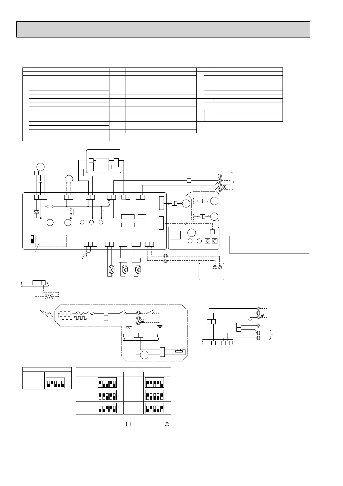
PCA-RP50GA PCA-RP50GA2 PCA-RP60GA PCA-RP71GA
PCA-RP100GA PCA-RP125GA PCA-RP140GA
SYMBOL NAME
P. B
I.B
C CAPACITOR(FAN MOTOR)
I.B
(
PCH-P50~P140GAH
models only
Indoor and Outdoor unit was applied, refer to Fig 1.
refer to the caution label located near this diagram.
Table 1
INDOOR POWER BOARD
INDOOR CONTROLLER BOARD
FUSE FUSE (T6.3AL250V)
ZNR VARISTOR
CN2L CONNECTOR(LOSSNAY)
CN32 CONNECTOR(REMOTE SWITCH)
CN41 CONNECTOR(HA TERMINAL-A)
CN51 CONNECTOR(CENTRALLY CONTROL)
SW1 SWITCH (MODEL SELECTION) See Table 1.
SW2 SWITCH (CAPACITY CODE) See Table 2.
SWE SWITCH(EMERGENCY OPERATION)
X1 RELAY(DRAIN PUMP)
X4 RELAY(FAN MOTOR)
BCR
FAN CONTROL ELEMENT
LED1 POWER SUPPLY(I.B)
POWER SUPPLY(R.B)
LED2
TRANSMISSION(INDOOR-OUTDOOR)LED3
P. B
CNDK
(RED)
1
MF
1 2 3
C
BLK
WHT
RED
1 3 1 3 1 3 1 35
FAN
(
)
WHT
SW2 SW1
1 2 3
DS
X4
X4 X1
When installing drain pump
(Optional part).
BCR
SWE
ON
OFF
Refer to tables 1
and 2 for service PCB.
CN31
DRAIN SENSOR
)
WHT
(OPTION)
DP
D.U.M
CNP
(BLU)
X1
When installing optional
drain pump disconnect
the CN31 jumper connector
and replace it with the
drain sensor (DS).
H1
2
3
RED
POWER
CNDK
(RED)
LED3 LED2 LED1
D.SENSOR
CN31
(
WHT
FS1
FS2
WHT
1. When work to supply power separately to
2. For power supply system of this unit,
Table 2
SW1
MODELS
PCA-RP·GA
PCH-P·GAH
Service board
1 2 3 4 5
ON
OFF
MODELS
PCA-RP50GA
PCH-P50GAH
PCA-RP50GA2
PCA-RP60GA
PCH-P60GAH
PCA-RP71GA
PCH-P71GAH
)
SYMBOL NAME
MF
MV
DP
DS
TB2
TB4
TB5,TB6
TH1
TH2
TH5
R.B
DC13.1V
YLW
POWER
CND
(ORN)
ZNR
INTAKE
CN20
(
RED
1 21 2 3
[Servicing]
Fasten terminal of the terminal board "TB4"equips lock system.
To remove the fastened terminal, pull it while pressing the protruding
portion (locking lever) of the terminal. The fastened terminal protruding
portion should face upward.
1
WHT
2
Service board
1 2 3 4 5
1 2 3 4 5
1 2 3 4 5
FAN MOTOR
VANE MOTOR
DRAIN PUMP (OPTION)
DRAIN SENSOR (OPTION)
TERMINAL BLOCK (HEATER) PCH-P.GAH
models only or option for PCA RP·GA models.
TERMINAL BLOCK(INDOOR/OUTDOOR CONNECTING LINE)
TERMINAL BLOCK(REMOTE CONTROLLER
TRANSMISSION LINE )
ROOM TEMP.THERMISTOR
(0°C/15k, 25°C/5.4k DETECT)
PIPE TEMP.THERMISTOR/LIQUID
(0°C/15k, 25°C/5.4k DETECT)
COND./EVA.TEMP.THERMISTOR
(0°C/15k, 25°C/5.4k DETECT)
WIRED REMOTE CONTROLLER BOARD
CN2S
(WHT)
1
2
ORN
BLK
1 2
POWER
CN2D(WHT)
FUSE
LIQUID
CN21
(
)
WHT
1 2
BLK
1 2
88H
GRN/YLW
SW2
ON
OFF
ON
OFF
ON
OFF
ORN
BRN
WHT
1 3
INDOOR/OUTDOOR
COMMUNICATION
CN3C(BLU)
CN41 CN2L
CN51 CN32
PIPE
CN29
)
(
)
BLK
1 2
BLK
BLK
BLK
1 2
TH2
TH5TH1
TB2
L
REDRED 5 3RED
N
BLU
HEATER
2
1
I.B
YLW
YLW
61
88H
MODELS
PCA-RP100GA
PCH-P100GAH
PCA-RP125GA
PCH-P125GAH
PCA-RP140GA
PCH-P140GAH
VAN E
CN6V
(
)
GRN
WIRELESS
CN90
(
)
WHT
REMOCON
CN22
(
)
BLU
1 2
BLU
BLU
CN24
(YLW)
Service board
1 2 3 4 5
1 2 3 4 5
1 2 3 4 5
6 6
RU
RECEIVER
2
TRANSMISSION WIRES DC12V
1
TB5
POWER SUPPLY
~(1PHASE)
230V 50Hz
26H
RED
6
REDGRY
5
ON
OFF
ON
OFF
ON
OFF
W.B
HEATER
50~71 TYPE
6 6
MV
100~140 TYPE
5 5
9
BZ
LED1 LED2 SW2 SW1
R.B
WIRELESS REMOTE CONTROLLER BOARD(OPTION)
RECEIVING UNIT
RU
BZ
BUZZER
LED1
LED(RUN INDICATOR)
LED2
LED(HOT ADJUST)
SW1
SWITCH(HEATING ON/OFF)
SW2
SWITCH(COOLING ON/OFF)
FS1,2
THERMAL FUSE(98°C10A:50GAH/117°C16A:100GAH
110°C16A:60,71,125,140GAH)
HEATER
H1
HEATER THERMAL SWITCH
26H
HEATER CONTACTOR
88H
TB4
YLW
S1
S2
ORN
S3
ORN
BRN
MV
MV
CNB
W.B
12
TB6
1 (Fig.1)
YLW
ORN
I.B
POWER
INDOOR/OUTDOOR
CND
COMMUNICATION
(ORN)
CN3C
(BLU)
Notes:
1. SymboIs used in wiring diagram above are, : Connector, : Terminal (block).
2. Indoor and outdoor connecting wires have poIarities, make sure to match terminal numbers (S1, S2, S3) for correct wirings.
3. Since the outdoor side electric wiring may change, be sure to check the outdoor unit electric wiring diagram for servicing.
4. This diagram shows the wiring of indoor and outdoor connecting wires (specification of 230V), adopting superimposed system for
power and signal.
+1: If indoor and outdoor units have separate power supplies, refer to Fig.1.
+2: For power supply system of this unit, refer to the caution label located near this diagram.
NAMESYMBOL
TO OUTDOOR UNIT
Please set the voltage using the remote
controller.
For the setting method, please refer to
the indoor unit Installation Manual.
TB2
L
RED
BLU
GRN/YLW
YLW
ORN
ORN
BRN
TB4
POWER SUPPLY
N
~(1PHASE)
230V 50Hz
S1
S2
TO OUTDOOR UNIT
S3
3131
64
Page 65
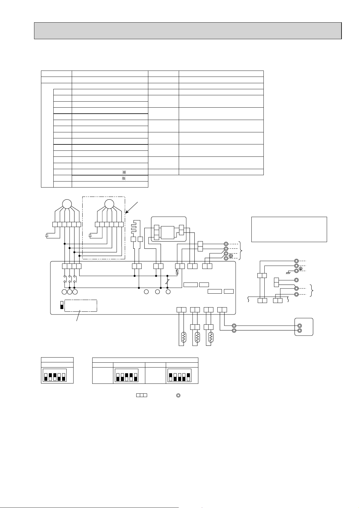
PCA-RP71HA PCA-RP125HA
[ LEGEND ]
SYMBOL
P. B
I. B
INDOOR POWER BOARD
INDOOR CONTROLLER BOARD
FUSE
FUSE (T6.3AL250V)
ZNR
VAR IST OR
CN2L
CONNECTOR (LOSSNAY)
CN32
CONNECTOR (REMOTE SWITCH)
CN41
CONNECTOR (HA TERMINAL-A)
CN51
CONNECTOR (CENTRALLY CONTROLL)
LED1
POWER SUPPLY (I. B)
LED2
POWER SUPPLY (R. B)
LED3
TRANSMISSION(INDOOR-OUTDOOR)
X1
RELAY (DEW PREVENTION HEATER)
X4
RELAY(FAN MOTOR)
X5
RELAY(FAN MOTOR)
X6
RELAY(FAN MOTOR)
SW1
SWITCH (MODEL SELECTION)
SWITCH (CAPACITY CODE) See Table 2.
SW2
SWITCH (EMERGENCY OPERATION)
SWE
NAME SYMBOL NAME
See Table 1.
MF1, MF2
C1, C2
H2
TB2
TB4
TB5,TB6
TH1
TH2
TH5
R. B
FAN MOTOR
CAPACITOR(FAN MOTOR)
DEW PREVENTION HEATER
TERMINAL BLOCK(INDOOR UNIT
POWER (OPTION))
TERMINAL BLOCK(INDOOR/OUTDOOR
CONNECTING LINE)
TERMINAL BLOCK(REMOTE CONTROLLER
TRANSMISSION LINE)
ROOM TEMP.THERMISTOR
(0°C/15k, 25°C/5.4k DETECT)
PIPE TEMP.THERMISTOR/LIQUID
(0°C/15k, 25°C/5.4k DETECT)
COND./ EVA.TEMP.THERMISTOR
(0°C/15k, 25°C/5.4k DETECT)
WIRED REMOTE CONTROLLER BOARD
ORN
654321
ORN
C1
RED
I.B
FAN
(WHT)
ON
OFF
Table 1
SW1
Service board
1 2 3 4 5
MF1
BLU
BLK
YLW
RED
BLK
BLU
WHT
WHT
YLW
C2
1357
X6 X5 X4
X6 X5 X4
SWE
SW2 SW1
Refer to tables 1
and 2 for service PCB.
ON
OFF
ORN
RED
654321
BRN
GRY
Table 2
MODELS
PCA-RP71HA
MF2
BLK
BLK
BLU
BLU
For PCA-RP125HA
CNDK
WHT
YLW
WHT
YLW
D.HEATER
CNC
(RED)
Service board
1 2 3 4 5
P. B
(RED)
H2
11
YLW
13 13 13 12
1
2
3
RED
YLW
ROWER
CNDK
(RED)
LED3 LED2 LED1
SW2
MODELS
ON
PCA-RP125HA
OFF
DC13.1V
WHT
ROWER
CND
(ORN)
ZNR
Service board
1 2 3 4 5
CN2S
(WHT)
1
2
YLW
ORN
BLK
WHT
13
INDOOR/OUTDOOR
ROWER
CN2D(WHT)
FUSE
INTAKE
CN20
(RED)
COMMUNICATION
CN3C(BLU)
CN41 CN2L
LIQUID
CN21
(WHT)
PIPE
CN29
(BLK)
12 12 12
WHT
WHT
BLK
12 13
TH1 TH2 TH5
ON
OFF
YLW
ORN
ORN
BRN
REMOCON
CN22
(BLU)
12
BLK
BLU
TB4
S1
TO
S2
OUTDOOR
S3
UNIT
CN32CN51
I.B
TB5
BLU
2
TRANSMISSION WIRES DC12V
1
Please set the voltage using the
remote controller.
For the setting method, please refer to
the indoor unit Installation Manual.
+1 (Fig.1)
YLW
ORN
POWER
INDOOR/OUTDOOR
CND
COMMUNICATION
(ORN)
CN3C
(BLU)
GRN/YLW
YLW
ORN
ORN
BRN
3131
RED
BLU
R.B
TB2
TB4
L
N
S1
S2
S3
1
TB6
2
POWER
SUPPLY
~(1PHASE)
230V 50Hz
TO
OUTDOOR
UNIT
Notes:
1. SymboIs used in wiring diagram above are, : Connector, : Terminal (block).
2. Indoor and outdoor connecting wires have poIarities, make sure to match terminal numbers (S1, S2, S3) for correct wirings.
3. Since the outdoor side electric wiring may change, be sure to check the outdoor unit electric wiring diagram for servicing.
4. This diagram shows the wiring of indoor and outdoor connecting wires (specification of 230V), adopting superimposed system for
power and signal.
+1: If indoor and outdoor units have separate power supplies, refer to Fig.1.
+2: For power supply system of this unit, refer to the caution label located near this diagram.
65
Page 66
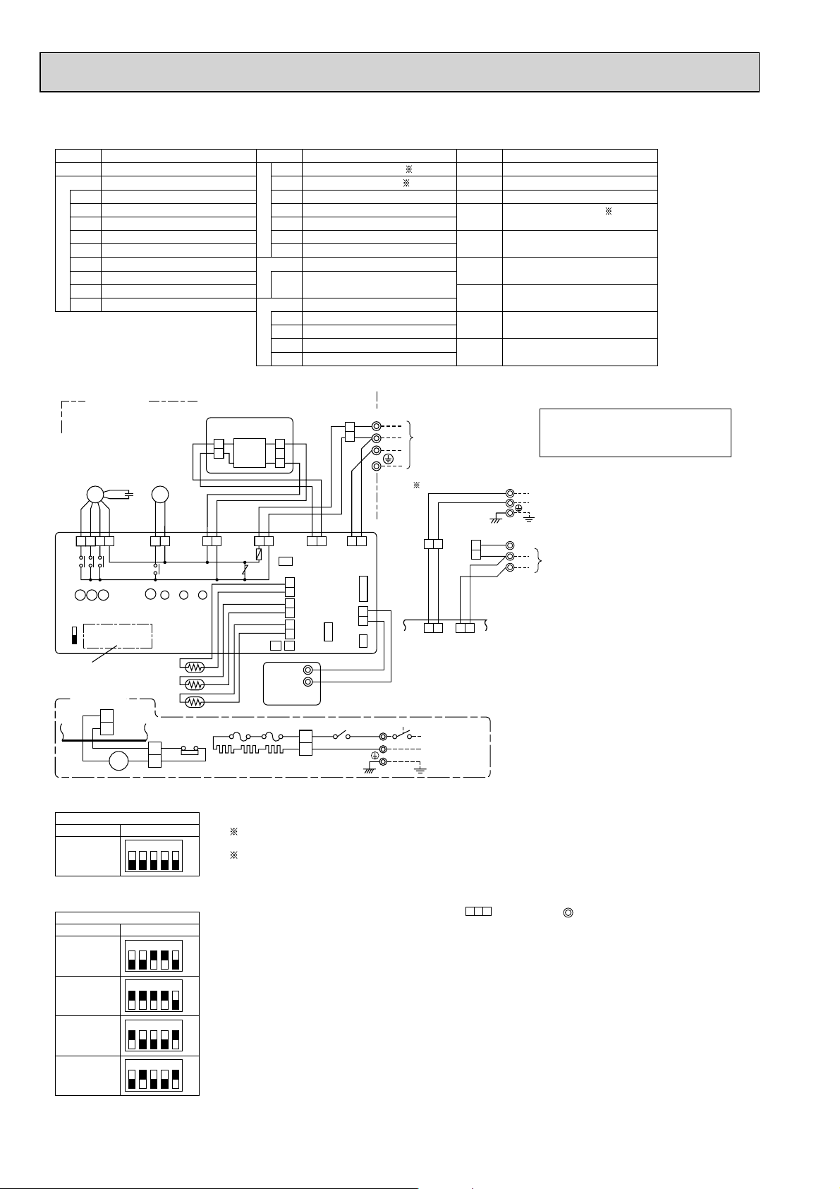
PSA-RP71GA PSA-RP100GA PSA-RP125GA PSA-RP140GA
SYMBOL NAME SYMBOL NAME SYMBOL NAME
P. B
I.B
INDOOR POWER BOARD
INDOOR CONTROLLER BOARD
FUSE FUSE (T6.3AL250V)
ZNR VARISTOR
CN2L CONNECTOR (LOSSNAY)
CN32 CONNECTOR (REMOTE SWITCH)
CN41 CONNECTOR (HA TERMINAL-A)
CN51 CONNECTOR (CENTRALLY CONTROL)
LED1 POWER SUPPLY (I.B)
POWER SUPPLY (R.B)
LED2
TRANSMISSION (INDOOR-OUTDOOR)LED3
INDOOR UNIT
MF
BLK
BLU
I.B
YLW
FAN
1357
(WHT)
X4X5X6
X6
X5 X4
SWE
ON
OFF
Refer to tables 1
and 2 for service PCB.
PSH -P.GAH
models only
2
1
I.B
YLW
16
YLW
ORN
RED
WHT
HEATER
(YLW)
88H
C
ML
YLW
LOUVER
13 13 13 12
CNL
(YLW)
X2
SW1SW2
CN24
6
5
YLW
P.B
YLW
POWER
CNDK
(RED)
X2
LED3 LED2 LED1
TH2
TH1
TH5
26H
RED
RED
RED
CN2S
(WHT)
2
1
WHT
DC13.1V
POWER
CND
(ORN)
ZNR
R.B
H
SWITCH (MODEL SELECTION) See Table 1.
SW1
I.B
SW2
SWITCH (CAPACITY CODE) See Table 2.
SWE SWITCH (EMERGENCY OPERATION)
RELAY (LOUVER)
X2
X4 RELAY (FAN MOTOR)
X5 RELAY (FAN MOTOR)
X6 RELAY (FAN MOTOR)
R.B
WIRED REMOTE CONTROLLER BOARD
TB6
TERMINAL BLOCK (REMOTE CONTROLLER
TRANSMISSION LINE)
HEATER
THERMAL FUSE (110°C16A)
FS1,2
HEATER
H
HEATER THERMAL SWITCH
26H
HEATER CONTACTOR
88H
TB4
WHT
INDOOR/OUTDOOR
COMMUNICATION
CN3C
(BLU)
WIRELESS
CN90
(WHT)
REMOCON
CN22
(BLU)
CN2L
CN32
BLU
BLU
TRANSMISSION
WIRES DC12V
88H
53
REDRED
GRN/YLW
YLW
ORNS1S2
BRN
ORN
13
2
1
RED
BLU
S3
TB2
L
N
CNSK
(RED)
3
2
1
YLW
ORN
FUSE
CN51
LIQUID
2
CN21
1
(WHT)
INTAKE
2
CN20
1
(RED)
PIPE
2
CN29
1
(BLK)
CN24 CN41
1
2
TB6
FS1FS2
1
WHT
2
BLK
POWER
CN2D
(WHT)
TO
OUTDOOR
UNIT
I.B
C CAPACITOR (FAN MOTOR)
MF
ML
TB2
FAN MOTOR
LOUVER MOTOR
TERMINAL BLOCK (HEATER) PSH-P·GAH
models only or option for PSA-RP·GA models.
TB4
TERMINAL BLOCK
(INDOOR/OUTDOOR CONNECTING LINE)
TH1
ROOM TEMP.THERMISTOR
(0°C/15k, 25°C/5.4k DETECT)
TH2
PIPE TEMP.THERMISTOR/LIQUID
(0°C/15k, 25°C/5.4k DETECT)
TH5
COND./EVA.TEMP.THERMISTOR
(0°C/15k, 25°C/5.4k DETECT)
ORN
3131
RED
BLU
GRY/YLW
RED
BLU
TB2
TB4
L
N
S1
S2
S3
1 (Fig.1)
YLW
BRN
ORN
POWER
INDOOR/OUTDOOR
CND
COMMUNICATION
(ORN)
CN3C
(BLU)
POWER SUPPLY
~(1 PHASE)
230V 50Hz
Please set the voltage using the
remote controller.
For the setting method, please refer to
the indoor unit Installation Manual.
POWER SUPPLY
~(1PHASE)
230V 50Hz
TO
OUTDOOR
UNIT
Table 1
MODELS
PSA-RP·GA
PSH-P·GAH
Table 2
MODELS
PSA-RP71GA
PSH-P71GAH
PSA-RP100GA
PSH-P100GAH
PSA-RP125GA
PSH-P125GAH
PSA-RP140GA
PSH-P140GAH
SW2
Service board
1 2 3 4 5
SW2
Service board
1 2 3 4 5
1 2 3 4 5
1 2 3 4 5
1 2 3 4 5
ON
OFF
ON
OFF
ON
OFF
ON
OFF
ON
OFF
1 ; When work to supply power separately to Indoor and Outdoor unit
was applied, refer to Fig1.
2 ; For power supply system of this unit, refer to the caution label
located near this diagram.
Notes:
1. SymboIs used in wiring diagram above are, : Connector, : Terminal (block).
2. Indoor and outdoor connecting wires have poIarities, make sure to match terminal
numbers (S1, S2, S3) for correct wirings.
3. Since the outdoor side electric wiring may change, be sure to check the outdoor unit
electric wiring diagram for servicing.
4. This diagram shows the wiring of indoor and outdoor connecting wires (specification
of 230V), adopting superimposed system for power and signal.
+1: If indoor and outdoor units have separate power supplies, refer to Fig.1.
+2: For power supply system of this unit, refer to the caution label located near this diagram.
66
Page 67
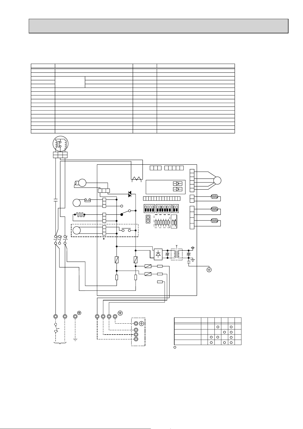
4-2. OUTDOOR UNIT
PUH-P71VHA PU-P71VHA PUH-P100VHA PU-P100VHA
SYMBOL
MC
MF
TH3
TH4
TH6
C3
C5
CH
52C
21S4
63H
49C
TB1
LEV
JA, JB(O.B)
COMPRESSOR (INNER THERMOSTAT)
FAN MOTOR (INNER THERMOSTAT)
THERMISTOR
MF CAPACITOR
MC CAPACITOR
CRANKCASE HEATER
MC CONTACTOR
4-WAY VALVE SOLENOID COIL
HIGH PRESSURE PROTECT SWITCH
INNER THERMOSTAT FOR MC
TERMINAL BLOCK
LINER EXPANSION VALVE
JUMPER WIRE
49C
MC
A1 A2 B1
A1 A2 B1
S
C
R
R
W
B
E
D
C5
2
/
T
1
1
/
L
1
C3
H
L
T
U
CH
6
/
T
21S4
3
52C
5
/
L
3
NAME SYMBOL
LIQUID TEMP
DISCHARGE TEMP
2-PHASE PIPE TEMP
MF
63H
A1
52C
A2
BLU
RED
O.B
FUSE1 (O.B)
FUSE2 (O.B)
FUSE3 (O.B)
FUSE4 (O.B)
X51 (O.B)
X52 (O.B)
F.C (O.B)
SW1 (O.B)
SW4 (O.B)
SW5 (O.B)
J1~J6 (O.B)
T (O.B)
CT (O.B)
LED1 (O.B)
LED2 (O.B)
CN31 (O.B)
OUTDOOR CONTROLLER BOARD
FUSE (6.3A 250V)
FUSE (6.3A 250V)
FUSE (6.3A 250V)
FUSE (6.3A 250V)
MC/CH RELAY
21S4 RELAY
FAN CONTROLLER
GROUP NUMBER ADDRESS
TEST RUN
FUNCTION SELECTION
MODEL SELECTION
TRANSFORMER
CURRENT TRANS
OPERATION CHECK DISPLAY LED
OPERATION CHECK DISPLAY LED
EMERGENCY OPERATION CONNECTOR
NAME
+2
O.B
1 2 3 4 5
3 2 1
CNVMNT
X51
X52
F.C
CT
CNM
ON
OFF
FUSE1
1413121110
SW5
CN31
MF3
(WHT)
3
1
52C
1
(PNK)
33
CH
(BLU)
1
3
21S4
1
(GRN)
1
FUSE2
FUSE4
FUSE3
4/S
R
CNMNT
(WHT)
(WHT)
LED1 (GRN)
LED2 (RED)
9 8 7 6 5 4 3 2 1
SW1
J1J2J3J4J5
+2
S1
S2
S3
J6
SW4
TH3/TH6
JA
JB
CNVEV
(WHT)
TH4
(WHT)
(RED)
6 5 4 3 2 1
TH4
1 2
TH6
TH3
1 2 3 4
LEV
B
R
L
E
U
D
LN
TB1
POWER SUPPLY
~/N
230V 50Hz
<Notes when servicing>
Some fastening terminals have a lock mechanism : When removing the fastening terminal, push the projection (locking lever) on the
terminal with your finger and pull it out.
Y
O
B
L
R
R
W
N
N
S3
S2
S1
S3
INDOOR
UNIT
S2
S1
TB4
+1 PUH-P71/P100VHA MODEL ONLY
+2 MODEL SELECTION
MODEL
PUH-P71VHA
PUH-P100VHA
PU-P71VHA
PU-P100VHA
: with jumper wire : without jumper wire
J1
J2
J4
J3
67
J5 J6
Page 68
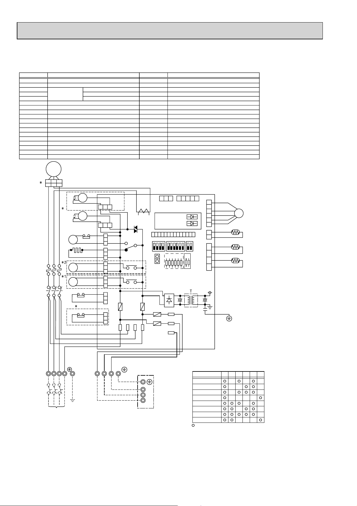
PUH-P71YHA PUH-P100YHA PUH-P125YHA PUH-P140YHA
PU-P71YHA PU-P100YHA PU-P125YHA PU-P140YHA
SYMBOL
MC
MF
TH3
TH4
TH6
C3
C4
CH
52C
21S4
SV
63H
51C
TB1
LEV
TB2
63L
JA, JB(O.B)
COMPRESSOR
FAN MOTOR (INNER THERMOSTAT)
THERMISTOR
MF CAPACITOR
MC CAPACITOR
CRANKCASE HEATER
MC CONTACTOR
4-WAY VALVE SOLENOID COIL
BYPASS VALVE SOLENOID COIL
HIGH PRESSURE PROTECT SWITCH
THERMAL RELAY
TERMINAL BLOCK
LINER EXPANSION VALVE
TERMINAL BLOCK
LOW PRESSURE PROTECT SWITCH
JUMPER WIRE
LIQUID TEMP
DICHARGE TEMP
2-PHASE PIPE TEMP
MC
A1 A2 B1
3
A1 A2 B1
U
V
51C
W
R
W
B
E
H
L
D
T
K
2
4
6
/
/
/
T
T
T
1
2
3
1
3
5
/
/
/
L
L
L
1
2
3
1
CH
52C
BLK
WHT
RED
C4
C3
52C
21S4
SV
MF
MF
63H
A1
A2
51C
95
96
1
63L
NAME
3
1
3
1
131313131313
(PNK)
(BLU)
(GRN)
(BLK)
51CM
(ORN)
(RED)
MF4
(WHT)
(WHT)
MF3
52
X51
CH
21S4
X52
X53
SV
FUSE2 FUSE1
63L
4/S T S R
F.C
SYMBOL
O.B
FUSE1 (O.B)
FUSE2 (O.B)
FUSE3 (O.B)
FUSE4 (O.B)
X51 (O.B)
X52 (O.B)
X53 (O.B)
F.C (O.B)
SW1 (O.B)
SW4 (O.B)
SW5 (O.B)
J1~J6 (O.B)
T (O.B)
CT (O.B)
LED1 (O.B)
LED2 (O.B)
CN31 (O.B)
CT
1413121110
CNM
SW5
ON
OFF
CN31
FUSE4
FUSE3
OUTDOOR CONTROLLER BOARD
FUSE (6.3A 250V)
FUSE (6.3A 250V)
FUSE (6.3A 250V)
FUSE (6.3A 250V)
MC/CH RELAY
21S4 RELAY
SV RELAY
FAN CONTROLLER
GROUP NUMBER ADDRESS
TEST RUN
FUNCTION SELECTION
MODEL SELECTION
TRANSFORMER
CURRENT TRANS
OPERATION CHECK DISPLAY LED
OPERATION CHECK DISPLAY LED
EMERGENCY OPERATION CONNECTOR
NAME
+4
O.B
1 2 3 4 5
3 2 1
CNVMNT
CNMNT
(WHT)
(WHT)
LED1 (GRN)
LED2 (RED)
9 8 7 6 5 4 3 2 1
SW1 SW4
J1J2J3J4J5
+4
S1
S2
S3
J6
CNVEV
TH3/TH6
JA
JB
(RED)
(WHT)
TH4
(WHT)
6 5 4 3 2 1
1 2
1 2 3 4
LEV
TH4
TH6
TH3
R
W
B
B
E
H
L
L
D
T
K
U
L1NL2 L3
TB1
POWER SUPPLY
3N~
400V 50Hz
<Notes when servicing>
Some fastening terminals have a lock mechanism: When removing the fastening terminal, push the projection (locking lever) on
the terminal with your finger and pull it out.
Y
L
W
TB2
S1 S2 S3
O
B
R
R
N
N
S3
INDOOR
UNIT
S2
S1
TB4
+1 PU(H)-P125/140YHA MODEL ONLY
+2 PUH-P71/P100/P125/P140YHA MODEL ONLY
+3 PU(H)-P71/100YHA MODEL ONLY
+4 MODEL SELECTION
MODEL
PUH-P71YHA
PUH-P100YHA
PUH-P125YHA
PUH-P140YHA
J1 J2
J3
PU-P71YHA
PU-P100YHA
PU-P125YHA
PU-P140YHA
: with jumper wire : without jumper wire
68
J4
J5
J6
Page 69
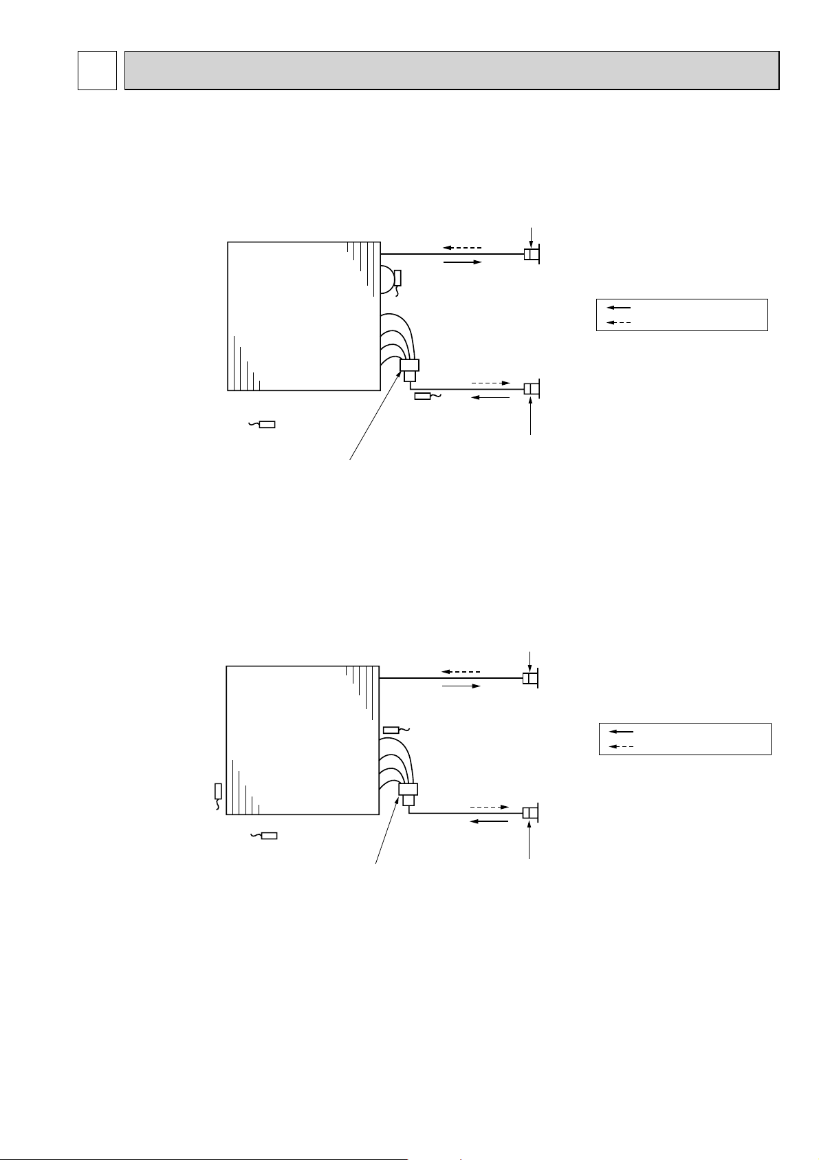
5
REFRIGERANT SYSTEM DIAGRAM
5-1. INDOOR UNIT
PLA-RP·BA(2) PLA-RP·AA(2) PMH-P·BA PEAD-RP·JA(L)
PEAD-RP·EA(2) PEAD-RP·GA PKA-RP·GAL PKA-RP·FAL(2)
PCA-RP·KA PCA-RP·GA(2) PCA-RP·HA PSA-RP·GA
PKA-RP·HAL
PKA-RP·KAL
Heat exchanger
Thermistor TH1
(Room temperature)
Heat exchanger
Distributor
with strainer(#50)
Strainer(#50)
Thermistor TH5
(Cond./Eva. temperature)
Thermistor TH2
Pipe temperature (Liquid)
Strainer(#50)
Refrigerant GAS pipe connection
(Flare)
Refrigerant flow in cooling
Refrigerant flow in heating
Refrigerant LIQUID pipe connection
(Flare)
Strainer (#50)
Refrigerant GAS pipe connection
(Flare)
Thermistor TH5
(Cond./ Eva.temperature)
Thermistor TH1
(Room temperature)
Thermistor TH2
Pipe temperature(Liquid)
Distributor with strainer
(#50/#50: HAL)
(#50/#100: KAL)
Refrigerant flow in cooling
Refrigerant flow in heating
Refrigerant LIQUID pipe connection
(Flare)
Strainer (#50)
6969
Page 70
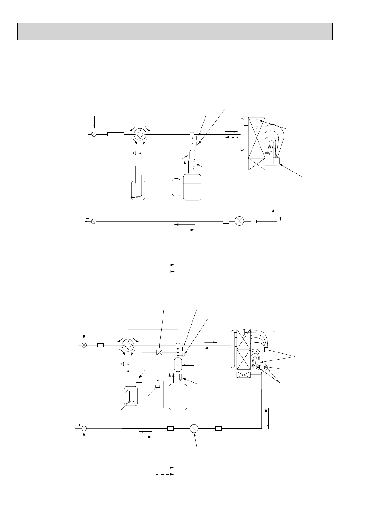
5-2. OUTDOOR UNIT
PUH-P71VHA PUH-P100VHA
PUH-P71YHA PUH-P100YHA
PU-P71VHA PU-P100VHA
PU-P71YHA PU-P100YHA
Ball valve
Refrigerant GAS pipe
15.88 (W5/8")
(#50)
Strainer
4-way valve
High pressure
protect switch
Service port
(check)
Outdoor heat exchanger
Thermistor
(TH6)
Refrigerant LIQUID pipe
9.52 (W3/8")
PUH-P125YHA
PUH-P140YHA
PU-P125YHA
PU-P140YHA
Ball valve
Refrigerant GAS pipe
15.88 (W5/8")
Refrigerant LIQUID pipe
9.52 (W3/8")
Service
port
(check)
Accumulator
Strainer
(#40)
Stop valve
(with service port)
Bypass valve
4-way
valve
(#50)
Strainer
Service
port
(check)
Accumulator
Strainer
(#40)
Strainer
(#100)
Low
pressure
protect
switch
Muffler
Compressor
Refrigerant flow in cooling
Refrigerant flow in heating
Compressor
Strainer
(#100)
Thermistor
(TH4)
(#100)
Strainer
(#100)
Strainer
Linear expansion valve
High pressure protect switch
Service port (check)
Muffler
Thermistor
(TH4)
Strainer
(#100)
Thermistor
(TH3)
Distributor
Thermistor
(TH6)
Distributor
Thermistor (TH3)
Capillary tube
(:4.0%:3.0-L200)%2
Stop valve
(with service port)
Linear expansion valve
Refrigerant flow in cooling
Refrigerant flow in heating
70
Page 71
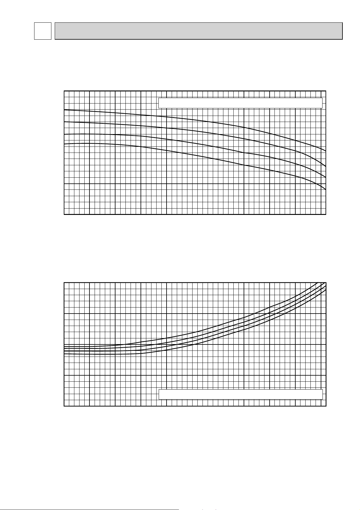
6
PERFORMANCE CURVES
6-1. FOR THE COMBINATION OF OUTDOOR UNIT
Cooling capacity
1.4
Indoor intake air wet-bulb temperature <W.B. :>
1.2
1.0
0.8
Cooling capacity ratio
0.6
-5 0 5 10 15 20 25 30 35 40 46
Outdoor intake air dry-bulb temperature <D.B. >
Cooling input
1.2
1.0
22
22
20
18
16
20
18
16
0.8
0.6
Cooling input ratio
Indoor intake air wet-bulb temperature <W.B. :>
0.4
-5 0 5 10 15 20 25 30 35 40 46
Outdoor intake air dry-bulb temperature <D.B. >
7171
Page 72
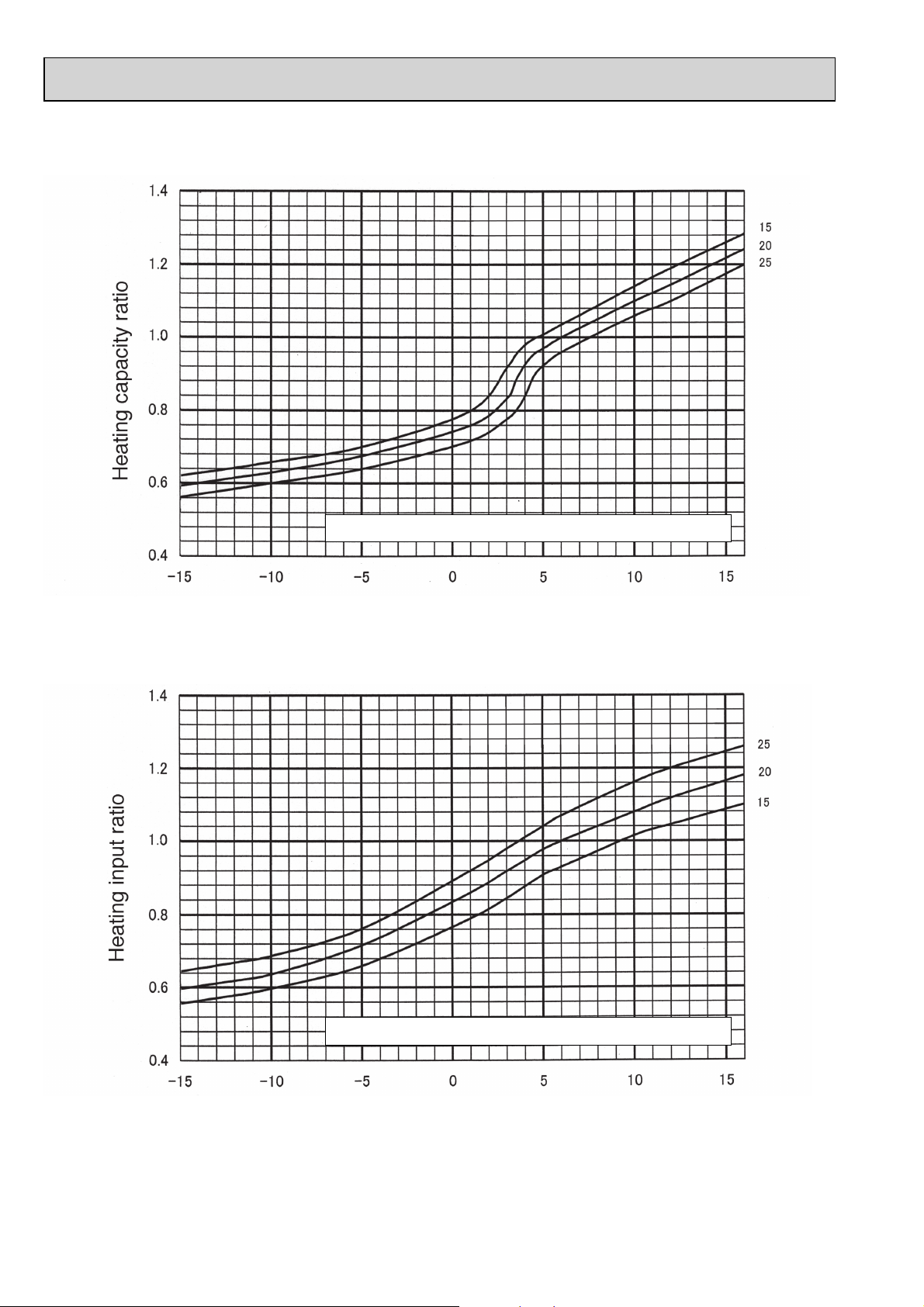
Heating capacity
Indoor intake air dry-bulb temperature <D.B. :>
Outdoor intake air wet-bulb temperature <W.B. :>
Heating input
Indoor intake air dry-bulb temperature <D.B. :>
Outdoor intake air wet-bulb temperature <W.B. :>
72
Page 73
7
CORRECTION FACTORS
7-1. COOLING CAPACITY CORRECTION FACTORS
Outdoor unit
PU(H)-P71VHA
PU(H)-P71YHA
PU(H)-P100VHA
PU(H)-P100YHA
PU(H)-P125YHA
1.00
1.00
1.00
Refrigerant piping length (one way)
0.988
0.985
0.981
0.966
0.957
0.946
0.946
0.931
0.914
0.929
0.908
0.885
0.913
0.886
0.858
55m50m40m30m20m10m5m
0.905
0.876
0.845
PU(H)-P140YHA
1.00
0.976
0.931
0.893
0.858
7-2. HEATING CAPACITY CORRECTION FACTORS
Outdoor unit
PUH-P71VHA
PUH-P71YHA
PUH-P100VHA
PUH-P100YHA
PUH-P125YHA
PUH-P140YHA
1.00
1.00
1.00
1.00
Refrigerant piping length (one way)
0.997
0.997
0.997
0.997
0.991
0.991
0.991
0.991
0.985
0.985
0.985
0.985
0.979
0.979
0.979
0.979
0.827
0.973
0.973
0.973
0.973
0.813
55m50m40m30m20m10m5m
0.970
0.970
0.970
0.970
7373
Page 74

APPLICABLE EXTENSION PIPE FOR EACH MODEL8
8-1. PIPE LENGTH
8-1-1. 1:1 SYSTEM
Pipe length
<Table 1> Maximum pipe length
Liquid
(mm)
(mm)
pipe
Gas
pipe
OD
Thickness
OD
Thickness
:9.52
P71
P100,P125,P140
<Marks in the table>
50m
[30m]
t0.8
The maximum pipe length
Charge-less pipe length
:6.35
t0.8
:12.7
t0.8
10m
[10m]
: It can be used.
: Cooling capacity is lowered.
: Additional refrigerant charge is required when
the pipe length exceeds 20m.
:15.88
t1.0
10m
[10m]
:12.7
t0.8
30m
[30m]
:9.52
t0.8
:15.88
t1.0
Standard size
50m
[30m]
Standard size
50m
[30m]
:19.05
t1.0
:15.88
t1.0
30m
[20m]
40m
[20m]
:12.7
t0.8
:19.05
t1.0
8-1-2. TWIN AND TRIPLE SYSTEM
(1) TWIN SYSTEM (2) TRIPLE SYSTEM
<Table 2> Maximum pipe length
Main pipe
(mm)
Branch
pipe
(mm)
[B, C]
H
Liquid pipe
[A]
Gas pipe
Liquid pipe
Gas pipe
Liquid pipe
Gas pipe
Liquid pipe
Gas pipe
Indoor unit
h
Distribution pipe
:6.35
:12.7
:9.52
:15.88
:12.7
:19.05
:6.35
:12.7
B
:9.52
15.88
:
Standard size
50m
[30m]
50m
[30m]
Indoor unit side
Indoor unit
C
Outdoor unit side
A
P100(RP50%2)P71(RP35%2)
:9.52
15.88
:
Standard size
50m
[30m]
50m
[30m]
Outdoor unit
:9.52
19.05
:
P125(RP60%2) • P140(RP71%2)
:12.7
:9.52
15.88
19.05
:
:
Standard size
50m
[30m]
:9.52
19.05
:
:12.7
19.05
:
h
H
Distribution pipe
<Table 3> Maximum pipe length
Main pipe
(mm)
[A]
Branch
pipe
(mm)
[B, C, D]
Indoor unit
Liquid pipe
Gas pipe
Liquid pipe
Gas pipe
Liquid pipe
Gas pipe
Liquid pipe
Gas pipe
B
:
:15.88
Standard size
ø6.35
ø12.7
[30m]
ø9.52
ø15.88
[30m]
ø12.7
ø19.05
Indoor unit side
Indoor unit
C
D
Indoor unit
Outdoor unit side
A
P140(RP50%3)
9.52
50m
50m
:
9.52
19.05
:
Outdoor unit
:
12.7
:19.05
<TWIN SYSTEM>
Total length A + B + C
P71-140: 50 m
<TRIPLE SYSTEM>
Total length A + B + C + D
P140: 50 m
74
Page 75

(3) Pipe size and refrigerant pipe limits.
Pipe size (mm) Actual piping length <m>
RP35,50
W12.7<1/2>
RP60,71
W15.88<5/8>
Liquid side
W9.52<3/8>
RP35,50
W6.35<1/4>
RP60,71
W9.52<3/8>
Total length
A+B+C+D
50m
Indoor ~
Indoor
|B-C|
8m
|B-C| |C-D| |B-D|
Branch pipe
B, C, D
20m
TWIN
TRIPLE
Outdoor
unit
71-140
140
Gas side
Outdoor unit side Indoor unit side Outdoor unit side Indoor unit side
W15.88<5/8>
Note1. The number of bends in the refrigerant pipe is respectively 8 or less in the range of <A+B> <A+C> <A+D>
2. PU(H)-P71,100,125,140 : 30m chargeless
Height difference <m>
Indoor ~
Outdoor
H50m h 1m 15
Indoor ~
Indoor
(Note 1)
No. of bend
Indoor unit
h
H
Distribution pipe
Indoor unit side
B
Indoor unit
C
Outdoor unit side
A
<TWIN SYSTEM>
Total length A + B + C
P71-140: 50 m
Outdoor unit
Indoor unit
h
H
Distribution pipe
B
<TRIPLE SYSTEM>
Total length A + B + C + D
P140: 50 m
Indoor unit side
Indoor unit
C
D
Indoor unit
Outdoor unit
Outdoor unit side
A
8-2. ADJUSTING THE AMOUNT OF REFRIGERANT
• Check additional refrigerant charging amount referring to table 5, 6 when liquid pipe is one size larger than standard diam-
eter.
<Table 5> Required additional charge when the pipe size is larger than the standard diameter (1:1 SYSTEM)
Max. pipe length
30m
40m
30m
40m
100 g per 1 m longer than 20 m
100 g per 1 m longer than 20 m
50 g per 1 m longer than 20 m
50 g per 1 m longer than 20 m
Refrigerant amount to be added
PUH-P71,P100
PUH-P125,P140
PU-P71,P100
PU-P125,P140
Liquid pipe dia.
Chargeless
:12.7
:12.7
:12.7
:12.7
20m
20m
20m
20m
<Table 6> Required additional charge when the pipe size is larger than the standard diameter (TWIN/TRIPLE SYSTEM)
Capacity
P71,100,125,140
If the calculation produces a negative number ( W 0), additional charging is not necessary.
L1:
:12.7 liquid pipe length (m)
L2:
:9.52 liquid pipe length (m)
:6.35 liquid pipe length (m)
L3:
When the extension pipe length (main piping + branch piping) exceeds 20 m
Additional refrigerant amount W(g) = (100 % L1) + (60 % L2) + (30 % L3) - 2000
<Table 7> Additional refrigerant charging amount for pipe of standard diameter
Additional refrigerant charging amount
for pipe length exceeding 30 m (kg)
31—40m
0.6kg
0.6kg
0.6kg
41—50m
1.2kg
1.2kg
1.2kg
Outdoor unit
PU(H)-P71V/YHA
PU(H)-P100V/YHA
PU(H)-P125,140YHA
Permitted
pipe length
50m or less
50m or less
50m or less
Amount of unit filling refrigerant (kg)
3.6kg
4.4kg
5.0kg
7575
Page 76

8-3. CAPACITY CURVE
100
95
90
85
80
Capacity ratio [%]
75
70
5 101520253035404550
Corrected pipe length [m]
Cooling
Heating
Cooling P71 model
Cooling P100 model
Cooling P125 model
Cooling P140 model
76
Page 77

9
AIR FLOW DATA
9-1. OUTLET AIR SPEED AND COVERAGE RANGE
PLA-RP35BA PLA-RP50BA PLA-RP60BA PLA-RP71BA
Air fl ow m³/min. 15 18 18 21 30 31 32
Air speed m/sec. 2.6 3.2 3.2 3.7 5.3 5.4 5.6
Coverage range m 4.1 4.8 4.8 5.6 8.0 8.2 8.5
PLA-RP100BA
PLA-RP125BA
PLA-RP140BA(2)
PLA-RP35AA
PLH-P35AAH
Air fl ow m³/min. 14 18 18 20 28 30 30
Air speed m/sec. 2.8 3.6 3.6 4.0 4.9 6.6 6.6
Coverage range m 4.0 5.2 5.2 5.7 7.4 8.9 8.9
PMH-P25BA PMH-P35BA PMH-P50BA
Air fl ow m³/min. 8.4 10.0 11.0
Air speed m/sec. 3.7 4.3 4.7
Coverage range m 5.9 7.0 7.7
PCA-RP50KA PCA-RP60KA PCA-RP71KA PCA-RP100KA PCA-RP125KA PCA-RP140KA
Air fl ow m³/min. 15 19 20 28 29 32
Air speed m/sec. 3.3 3.1 3.2 3.6 3.7 4.1
Coverage range m 9.0 9.6 10.1 12.5 12.9 14.2
PCA-RP50GA
PCH-P50GAH
Air fl ow m³/min. 13 18 18 25 34 34
Air speed m/sec. 3.7 3.8 3.8 4.1 4.4 4.4
Coverage range m 8.8 10.4 10.4 12.6 15.2 15.2
PCA-RP71HA PCA-RP125HA
Air fl ow m³/min. 19 38
Air speed m/sec. 2.9 4.2
Coverage range m 7.9 13.2
PLA-RP50AA
PLH-P50AAH
PCA-RP60GA
PCH-P60GAH
PLA-RP60AA
PLH-P60AAH
PCA-RP71GA
PCH-P71GAH
PLA-RP71AA
PLH-P71AAH
PLA-RP100AA2
PLH-P100AAH
PCA-RP100GA
PCH-P100GAH
PLA-RP125AA2
PLH-P125AAH
PCA-RP125GA
PCH-P125GAH
PLA-RP140AA2
PLH-P140AAH
PCA-RP140GA
PCH-P140GAH
PKA-RP35HAL PKA-RP50HAL
Air fl ow m³/min. 12 12
Air speed m/sec. 6.1 6.1
Coverage range m 10.8 10.8
PKA-RP60KAL PKA-RP71KAL PKA-RP100KAL
Air fl ow m³/min. 22 22 26
Air speed m/sec. 6.0 6.0 6.8
Coverage range m 14.3 14.3 16.1
PKA-RP35GAL
PKH-P35GALH
Air fl ow m³/min. 12 12
Air speed m/sec. 5.3 5.3
Coverage range m 10 10
PKA-RP60FAL
PKH-P60FALH
Air fl ow m³/min. 20 20 28
Air speed m/sec. 4.9 4.9 5.4
Coverage range m 12.4 12.4 15.3
PSA-RP71GA
PSH-P71GAH
Air fl ow m³/min. 18 31 33 35
Air speed m/sec. 2.6 4.5 4.8 4.9
Coverage range m 8.3 14.3 15.2 16.1
w
The air coverage range is the distance to which the 0.25m/sec air can reach,when air is blown out horizontally from the unit at the High notch position.
The coverage range should be used only as a general guideline since it varies according to the size of the room and the furniture inside the room.
PKA-RP50GAL
PKH-P50GALH
PKA-RP71FAL
PKH-P71FALH
PSA-RP100GA
PSH-P100GAH
PKA-RP100FAL
PKH-P100FALH
PSA-RP125GA
PSH-P125GAH
PSA-RP140GA
PSH-P140GAH
7777
Page 78

9-2. PLA-RP·BA(2)
9-2-1 FRESH AIR INTAKE AND BRANCH DUCT
1.
Branch duct hole and fresh air intake hole (Fig. 1)
At the time of i nstallation, use the duct holes ( cut out) located at the positions shown in Fig.1, as and when required.
• A fresh air intake hole for the optional multi-functional casement can also be made.
Note:
The figure marked with * in the drawing represent the dimensions of the main unit excluding those of the optional
multi function casement.
When installing the optional multi-functional casement, add 135 mm to the dimensions marked on the figure.
When installing the branch ducts, be sure to insulate adequately.
Otherwise condensation and dripping may occur.
Fresh air intake hole
Refrigerant pipe
Indoor unit
Branch duct hole
Drain pipe
Branch duct
hole diagram
(view from
either side)
:175 burring hole pitch
90
70°
100 100 90
350
:150 cut out hole
Fresh air intake hole diagram
3-:2.8 burring hole
120
*158
100
130
*155
*167
14-:2.8 burring hole
:125 burring
hole pitch
120
:100 cut
out hole
Ceiling
Fig. 1
2. Fresh air intake (Installation at site)
● By mounting the optional multi-functional casement to the indoor unit main body, and mounting the duct and duct flange
(option) onto it further, fresh exterior air intake can be accomplished.
(The mounting of the multi-functional casement increase the height of the ceiling plenum by 135 mm.)
Multi-functional
casement
(Option)
Multi-functional casement
(Option)
78
Page 79

3. Fresh air intake volume & static pressure characteristics
PLA-RP35~71BA
At using multi-functional casement, standard filter
50
0
-50
2 - inlet
-100
Static pressure[Pa]
-150
1 - inlet
-200
01234 56
Air flow rate [m3/min]
Direct intake to unit
50
0
-50
-100
Static pressure[Pa]
-150
-200
01234 56
Air flow rate [m
3
/min]
PLA-RP100~140BA(2)
At using multi-functional casement, standard filter
50
0
-50
2 - inlet
-100
Static pressure[Pa]
-150
1 - inlet
-200
02468
Direct intake to unit
50
Air flow rate [m
3
/min]
At using multi-functional casement, high efficiency filter
50
0
-50
-100
Static pressure[Pa]
-150
-200
01234 56
Air flow rate [m
3
/min]
1 - inlet
2 - inlet
At using multi-functional casement, high efficiency filter
50
0
-50
-100
Static pressure[Pa]
-150
-200
02468
Air flow rate [m
3
/min]
79
0
-50
-100
Static pressure[Pa]
-150
-200
02468
1 - inlet
Air flow rate [m
3
/min]
2 - inlet
Page 80
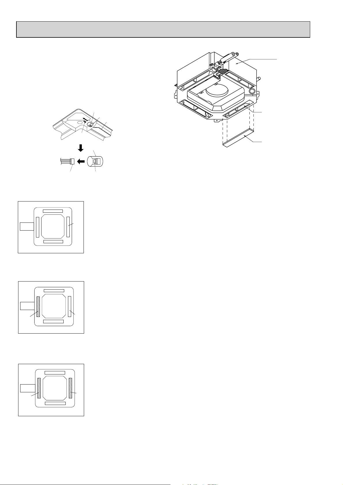
4. Change of outlet numbers
[The optional air outlet is necessary.]
To change the air outlet number to 3-, or 2-way outlet, the
outlet number should be closed with the operational air
outlet shutter.
(When the air outlets are closed, close the vane by
removing the vane connector.)
Indoor unit
Button
Vane motor
Up/down vanes
Connector
Vane motor
Connector
Button
5. Branch duct and change of outlet numbers
<4- way air flow and branch duct>
Branch
duct
Air intake
+ Branch duct should be connected to one of the branch duct holes on the main unit.
Air
outlet
Outlet concave
portion
Air outlet shutter plate
(Option)
<3- way air flow and branch duct>
Branch
duct
Air
outlet
closed
position
<2- way air flow and branch duct>
Branch
duct
Air
Air
outlet
outlet
closed
closed
position
position
Air intake
Air intake
+ Close the outlet on the side or branch duct and air flows in 3 directions.
Air
outlet
+ The outlet on the side or branch duct and one of the other outlets are closed.
Air flow in 2 directions.
Air
outlet
closed
position
80
Page 81
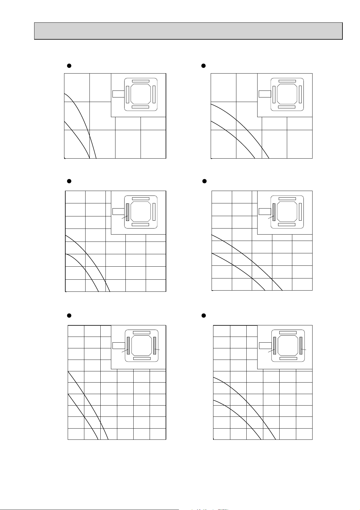
PLA-RP71BA
4-way air flow (horizontal vane) Round duct 4-way air flow (horizontal vane) Rectangular duct
30
20
30
Duct Duct
20
10
Static pressure [Pa]
High
Low
0
02
468
Air flow rate [m
3
/min]
3-way air flow (horizontal vane) Round duct 3-way air flow (horizontal vane) Rectangular duct
80
70
High
Duct
Close
3
/min]
60
50
40
30
Static pressure [Pa]
20
Low
10
0
0246810
Air flow rate [m
10
Static pressure [Pa]
High
Low
0
02468
Air flow rate [m
3
/min]
80
70
60
Duct
Close
50
40
30
Static pressure [Pa]
High
20
Low
10
0
0246810
Air flow rate [m
3
/min]
2-way air flow (horizontal vane) Round duct
100
90
80
Duct
Close
70
60
50
40
Static pressure [Pa]
30
20
High
Low
10
0
024681012
Air flow rate [m3/min]
Close
2-way air flow (horizontal vane) Rectangular duct
100
90
80
70
60
50
40
Static pressure [Pa]
30
20
Low
10
0
0 2 4 6 8 10 12
Duct
Close
High
Air flow rate [m
3
/min]
• Use 1 of the 2 duct holes on the indoor unit.
• Air flow rate of PLA-RP35~60BA can be calculated from the air flow rate based on the characteristic
of the duct for PLA-RP71BA.
• Use the optional air outlet shutter plate (PAC-SH51SP-E) for 3-way and 2-way air flow.
Close
81
Page 82
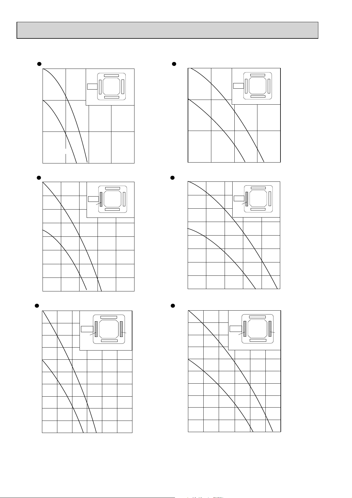
PLA-RP125BA
4-way air flow (horizontal vane) Round duct 4-way air flow (horizontal vane) Rectangular duct
30
30
Low
Duct
High
Duct
High
Duct
20
10
Static pressure [Pa]
Low
0
02468
Air flow rate [m
High
3
/min] Air flow rate [m3/min]
3-way air flow (horizontal vane) Round duct 3-way air flow (horizontal vane) Rectangular duct
80
70
60
50
40
Static pressure [Pa]
30
Duct
Close Close
High
20
10
Static pressure [Pa]
0
02468
80
70
60
50
40
Static pressure [Pa]
30
20
10
0
0246810
Low
Air flow rate [m3/min] Air flow rate [m3/min]
20
10
0
0246 810
Low
2-way air flow (horizontal vane) Round duct 2-way air flow (horizontal vane) Rectangular duct
100
90
80
70
60
50
40
Close
High
Static pressure [Pa]
30
Low
20
10
0
024681012
Air flow rate [m3/min] Air flow rate [m3/min]
Close
100
90
80
70
60
50
40
Static pressure [Pa]
30
20
10
0
024681012
Low
DuctDuct
Close
High
Close
• Use 1 of the 2 duct holes on the indoor unit.
• Air flow rate of PLA-RP100BA, PLA-RP140BA(2) can be calculated from the air flow rate based on the characteristic
of the duct for PLA-RP125BA.
• Use the optional air outlet shutter plate (PAC-SH51SP-E) for 3-way and 2-way air flow.
82
Page 83
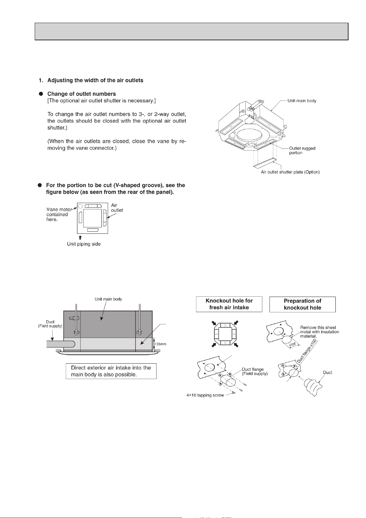
9-3. PLA-RP·AA, PLA-RP·AA2
9-3-1. FRESH AIR INTAKE AMOUNT
2. Fresh air intake (Installation at site)
● By mounting the optional multi-functional casement to the indoor unit main body, and mounting the duct and duct flange (option) onto it fur-
ther, fresh exterior air intake can be accomplished.
(The mounting of the multi-functional casement increase the height of the ceiling plenum by 135 mm.)
Multi-functional
casement
(Option)
Multi-functional casement
(Option)
83
Page 84
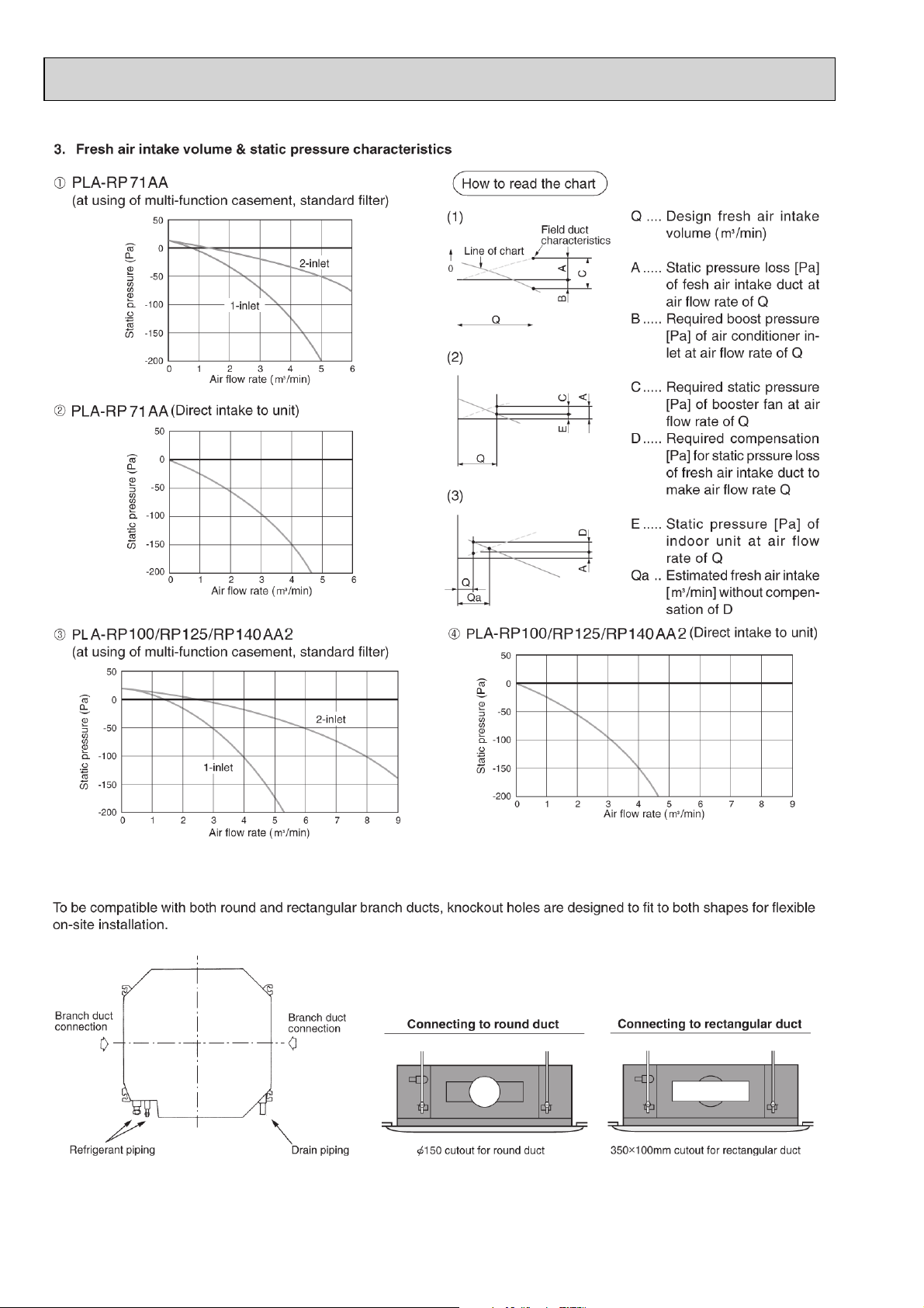
9-3-2. BRANCH DUCT (Installation at site)
84
Page 85
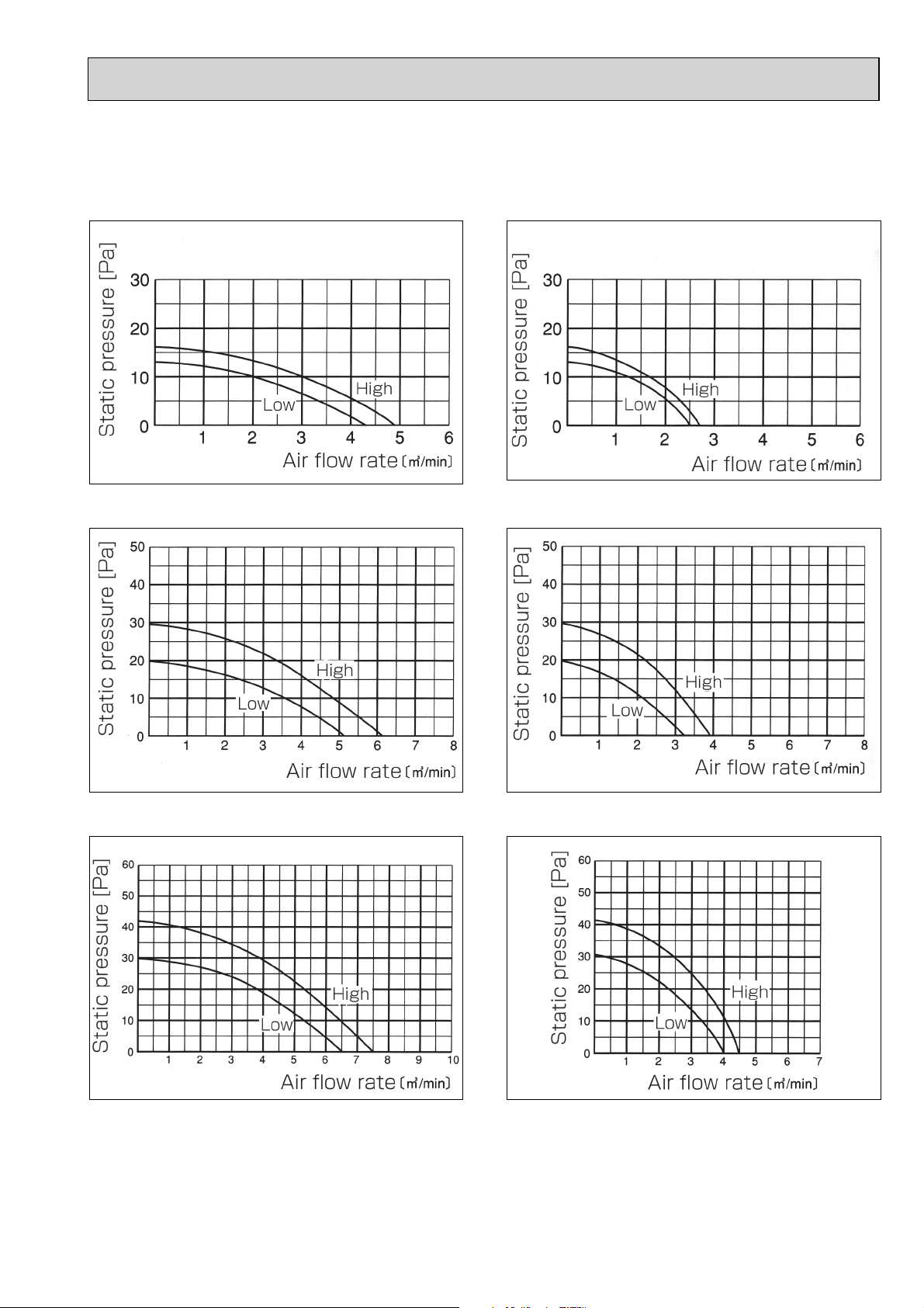
Branch duct air flow rate/static pressure characteristics
PLA-RP35AA
4-way air flow (horizontal vane) Rectangular duct 4-way air flow (horizontal vane) Round duct
3-way air flow (horizontal vane) Rectangular duct 3-way air flow (horizontal vane) Round duct
2-way air flow (horizontal vane) Rectangular duct 2-way air flow (horizontal vane) Round duct
85
Page 86
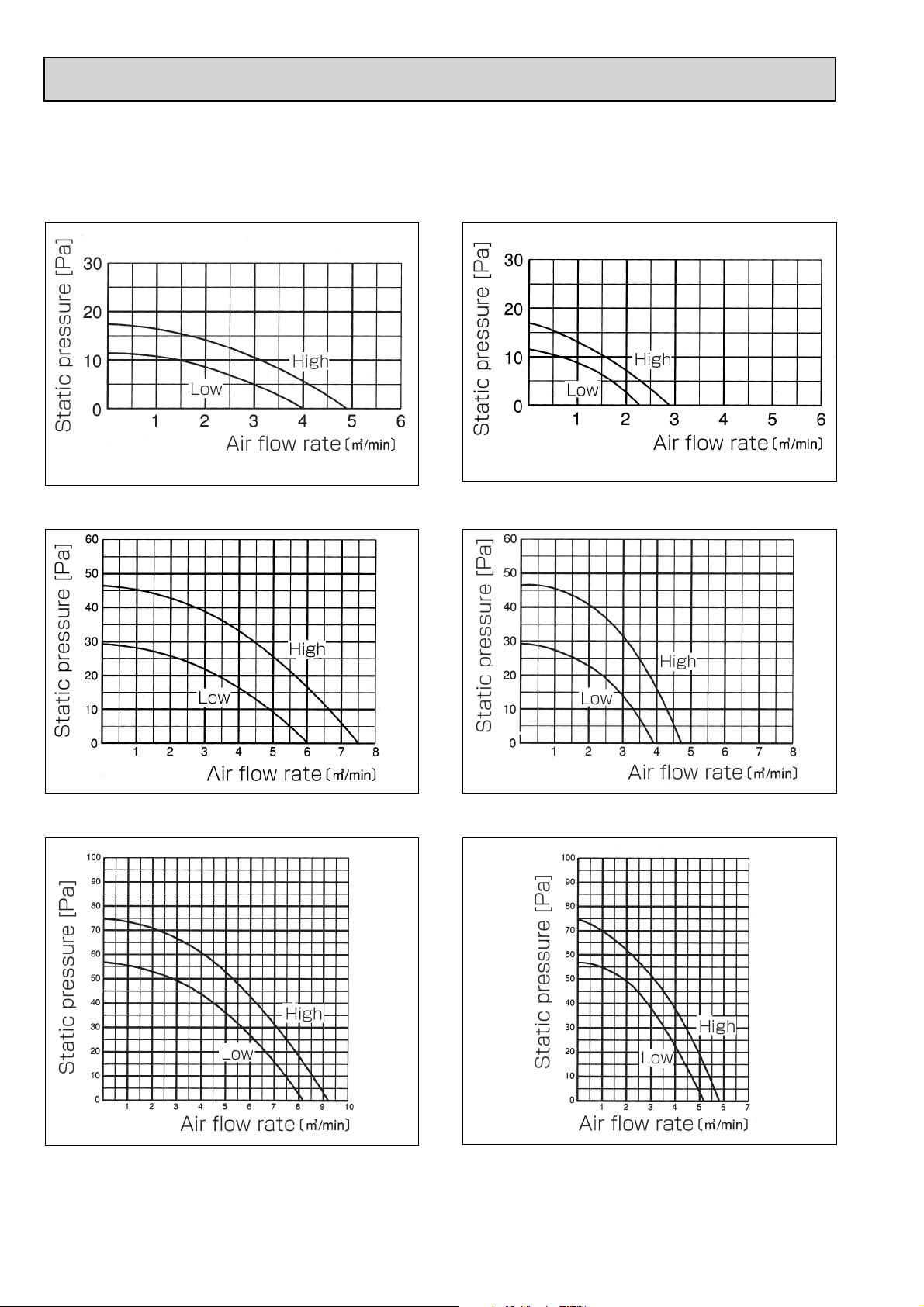
PLA-RP50AA
PLA-RP60AA
4-way air flow (horizontal vane) Rectangular duct 4-way air flow (horizontal vane) Round duct
3-way air flow (horizontal vane) Rectangular duct 3-way air flow (horizontal vane) Round duct
2-way air flow (horizontal vane) Rectangular duct 2-way air flow (horizontal vane) Round duct
86
Page 87
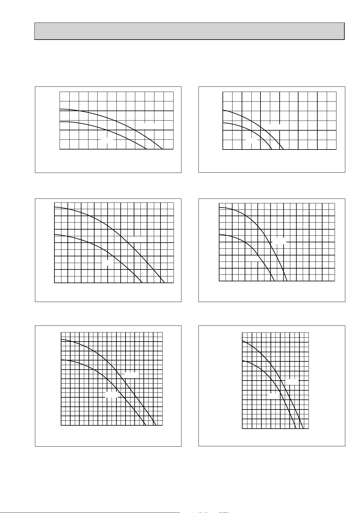
PLA-RP71AA
4-way air flow (horizontal vane) Rectangular duct 4-way air flow (horizontal vane) Round duct
Static pressure [Pa]
30
20
10
High
Low
0
123456
Air flow rate [m
3
/min]
Static pressure [Pa]
30
20
10
High
Low
0
123456
Air flow rate [m
3-way air flow (horizontal vane) Rectangular duct 3-way air flow (horizontal vane) Round duct
Static pressure [Pa]
60
50
40
30
20
High
Low
10
0
1 23 4 56789
Air flow rate [m
3
/min]
60
50
40
30
20
10
Static pressure [Pa]
High
Low
0
123456789
Air flow rate [m
3
/min]
3
/min]
2-way air flow (horizontal vane) Rectangular duct 2-way air flow (horizontal vane) Round duct
100
Static pressure [Pa]
90
80
70
60
50
40
30
20
10
0
1234 567891011
Low
High
Air flow rate [m
3
/min]
100
90
80
70
60
50
40
30
20
Static pressure [Pa]
10
0
1234567
Air flow rate [m
Low
High
3
/min]
87
Page 88
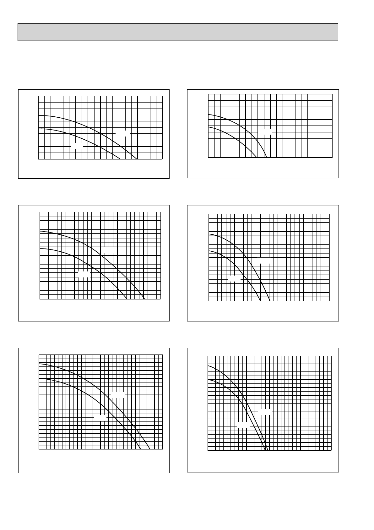
PLA-RP100AA2
4-way air flow (horizontal vane) Rectangular duct 4-way air flow (horizontal vane) Round duct
Static pressure [Pa]
50
40
30
20
10
0
1234 5678910
Low
High
Air flow rate [m
3
/min]
Static pressure [Pa]
50
40
30
20
10
0
Low
1234 5678910
High
Air flow rate [m
3-way air flow (horizontal vane) Rectangular duct 3-way air flow (horizontal vane) Round duct
100
Static pressure [Pa]
90
80
70
60
50
40
30
20
10
0
1234567 891011121314
Low
High
Air flow rate [m
3
/min]
100
90
80
70
60
50
40
Static pressure [Pa]
30
20
10
0
Low
1234567 891011121314
High
Air flow rate [m
3
3
/min]
/min]
2-way air flow (horizontal vane) Rectangular duct 2-way air flow (horizontal vane) Round duct
Static pressure [Pa]
120
110
100
90
80
70
60
50
40
30
20
10
0
2 3 4 5 6 7 8 9 10 11 12 13 14 15 16
1
High
Low
Air flow rate [m
3
/min]
120
110
100
90
80
70
60
50
40
30
Static pressure
20
10
0
1
Low
2 3 4 5 6 7 8 9 10 11 12 13 14 15 16
High
Air flow rate [m
88
3
/min]
Page 89
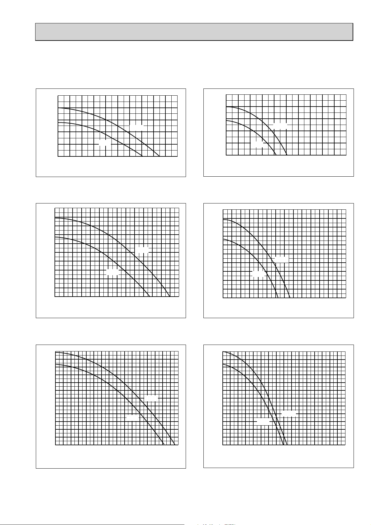
PLA-RP125AA2
PLA-RP140AA2
4-way air flow (horizontal vane) Rectangular duct 4-way air flow (horizontal vane) Round duct
Static pressure [Pa]
50
40
30
20
10
0
Low
12 34 567 8 910
High
Air flow rate [m
Static pressure [Pa]
50
40
30
20
10
0
12345678910
Low
High
Air flow rate [m
3
/min]
3-way air flow (horizontal vane) Rectangular duct 3-way air flow (horizontal vane) Round duct
100
Static pressure [Pa]
90
80
70
60
50
40
30
20
10
0
1234567891011121314
Low
High
Air flow rate [m
3
/min]
100
Static pressure [Pa]
90
80
70
60
50
40
30
20
10
0
1234567891011121314
Low
High
Air flow rate [m
3
/min]
3
/min]
2-way air flow (horizontal vane) Rectangular duct 2-way air flow (horizontal vane) Round duct
120
100
Static pressure [Pa]
110
90
80
70
60
50
40
30
20
10
0
2 3 4 5 6 7 8 9 10 11 12 13 14 15 16
1
Air flow rate [m
Low
High
3
/min]
120
110
100
90
80
70
60
50
40
30
Static pressure[Pa]
20
10
High
Low
0
2 3 4 5 6 7 8 9 10 11 12 13 14 15 16
1
Air flow rate [m
89
3
/min]
Page 90

9-4. PMH-P·BA
Air capacity taken from outside
PMH-P·BA series is possible to take outside air.
When taking air from the outside, the duct fan can be used.
The air capacity should be 20% or less of the air flow SPEC(Hi).
PMH-P25BA
PMH-P35BA
PMH-P50BA
How to read curves
Q
Duct characteristics
at site
Curve in the
graph below.
0
250 288.5
Air flow
(Hi)
8.4m
10.0m
11. 0m
A
C
B
90
4-W2.8
100
W
108
W
122
Flesh air intake hole
(Knockout)
Flesh air intake hole
(Knockout)
Air capacity taken outside
3
/min
3
/min
3
/min
1.6m
2.0m
2.2m
3
/min
3
/min
3
/min
Q…Planned amount of fresh air intake <m³/min>
A…Static pressure loss of fresh air intake duct system with air flow amount Q <Pa>
B…Forced static pressure at air conditioner inlet with air flow amount Q <Pa>
C…Static pressure of booster fan with air flow amount Q <Pa>
A
EC
Q
D…Static pressure loss increase amount of fresh air intake duct system for air flow amount Q <Pa>
E…Static pressure of indoor unit with air flow amount Q <Pa>
Qa…Estimated amount of fresh air intake without D <m³/min>
AD
Q
Qa
50.0
Characteristic diagram of air capacity taken from outside
0.0
2 intakes
1 intake
-50.0
Static pressure (Pa)
-100.0
0.0 0.5 1.0
Air flow (m
1.5 2.0 2.5
3
/min)
90
Page 91
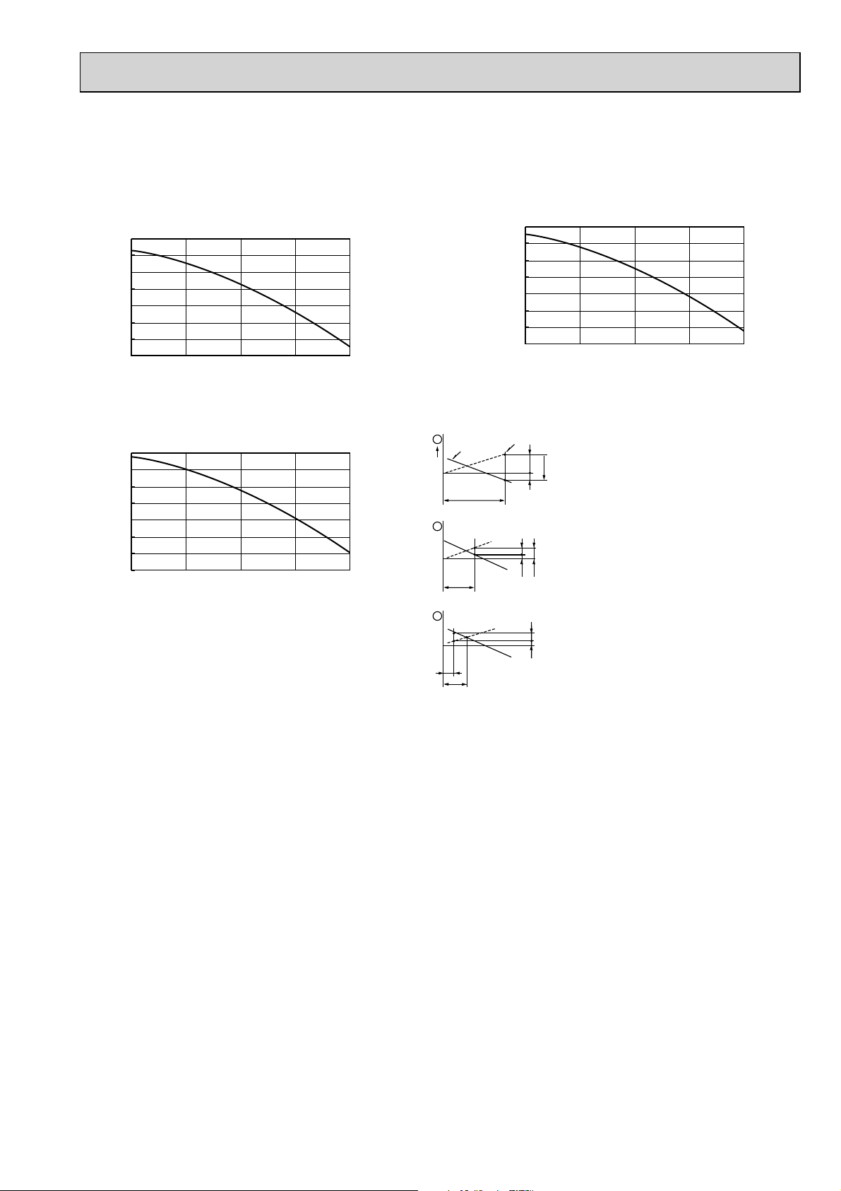
9-5. PCA-RP·KA
Fresh air intake amount & static pressure characteristics
PCA-RP50KA
PCA-RP60, 71KA
50
0
-50
-100
-150
-200
-250
Static pressure[Pa]
-300
0 1 2 3 4
Airflow rate[m³/min]
PCA-RP100, 125, 140KA
50
0
-50
-100
-150
-200
-250
Static pressure[Pa]
-300
0 1 2 3 4
Airflow rate[m³/min]
50
0
-50
-100
-150
-200
-250
Static pressure[Pa]
-300
0 1 2 3 4
How to read curves
Q
Duct characteristics
at site
EC
Curve in the
1
graphs
0
2
3
Q
Airflow rate[m³/min]
Q…Designed amount of fresh air intake
A
C
B
A
A…Static pressure loss of fresh air
intake duct system with airflow
amount Q <Pa>
B…Forced static pressure at air conditioner
inlet with airflow amount Q
C…Static pressure of booster fan with
airflow amount Q <Pa>
D…Static pressure loss increase amount
of fresh air intake duct system for
airflow amount Q <Pa>
E…Static pressure of indoor unit with
airflow amount Q <Pa>
Qa…Estimated amount of fresh air
intake without D <m3/min>
<m3/min>
<Pa>
Q
Qa
AD
91
Page 92

9-6. PEAD-RP·JA(L)
Fan performance
PEAD-RP35JA(L)
(External static pressure 35Pa) 220-240V 50Hz
60
50
Limit
40
Rated point
30
20
External static pressure (Pa)
10
0
7 9 11 13 15 17 19 21
Low
Airflow rate(m3/min)
High
Middle
PEAD-RP35JA(L)
(External static pressure 100Pa) 220-240V 50Hz
120
110
100
Limit
90
80
70
60
50
40
External static pressure (Pa)
30
20
10
0
7 9 11 13 15 17 19 21
Airflow rate(m3/min)
Rated point
High
Middle
Low
PEAD-RP35JA(L)
(External static pressure 50Pa) 220-240V 50Hz
70
60
Limit
50
40
30
20
External static pressure (Pa)
10
0
7 9 11 13 15 17 19 21
Low
Rated point
High
Middle
Airflow rate(m3/min)
PEAD-RP35JA(L)
(External static pressure 70Pa) 220-240V 50Hz
90
80
Limit
70
60
Rated point
High
PEAD-RP35JA(L)
(External static pressure 150Pa) 220-240V 50Hz
170
160
150
140
Limit
130
120
110
100
90
80
70
60
50
External static pressure (Pa)
40
30
20
10
0
7 9 11 13 15 17 19 21
Airflow rate(m3/min)
Rated point
Middle
Low
High
50
40
30
Middle
Low
External static pressure (Pa)
20
10
0
0
7 9 11 13 15 17 19 21
Airflow rate(m3/min)
92
Page 93

PEAD-RP50JA(L)
(External static pressure 35Pa) 220-240V 50Hz
70
External static pressure (Pa)
60
50
40
30
20
10
0
Limit
High
Rated point
Middle
Low
91419
Airflow rate(m3/min)
PEAD-RP50JA(L)
(External static pressure 50Pa) 220-240V 50Hz
80
70
Limit
3
/min)
High
Rated point
91419
External static pressure (Pa)
60
50
40
30
20
10
0
Low
Middle
Airflow rate(m
PEAD-RP50JA(L)
(External static pressure 70Pa) 220-240V 50Hz
100
PEAD-RP50JA(L)
(External static pressure 100Pa) 220-240V 50Hz
130
120
110
100
External static pressure (Pa)
Limit
90
80
70
60
50
40
30
20
10
0
Low
Rated point
High
Middle
91419
Airflow rate(m3/min)
PEAD-RP50JA(L)
(External static pressure 150Pa) 220-240V 50Hz
180
170
160
150
140
130
120
110
100
External static pressure (Pa)
Limit
90
80
70
60
50
40
30
20
10
0
Low
Airflow rate(m3/min)
Rated point
High
Middle
91419
External static pressure (Pa)
90
80
Limit
70
60
50
40
30
20
10
0
Low
Rated point
High
Middle
91419
Airflow rate(m3/min)
93
Page 94

PEAD-RP60JA(L)
(External static pressure 35Pa) 220-240V 50Hz
60
50
Limit
40
30
20
Rated point
High
Middle
External static pressure (Pa)
10
0
10 15 20 25 30
Low
Airflow rate(m3/min)
PEAD-RP60JA(L)
(External static pressure 50Pa) 220-240V 50Hz
70
60
Limit
50
40
30
20
External static pressure (Pa)
10
0
10 15 20 25 30
Low
Rated point
High
Middle
Airflow rate(m3/min)
PEAD-RP60JA(L)
(External static pressure 70Pa) 220-240V 50Hz
90
PEAD-RP60JA(L)
(External static pressure 100Pa) 220-240V 50Hz
120
110
100
90
Limit
80
70
60
50
40
External static pressure (Pa)
30
20
10
0
10 15 20 25 30
Low
Rated point
High
Middle
Airflow rate(m3/min)
PEAD-RP60JA(L)
(External static pressure 150Pa) 220-240V 50Hz
170
160
150
140
130
120
110
100
External static pressure (Pa)
90
80
70
60
50
40
30
20
10
Limit
0
10 15 20 25 30
Airflow rate(m3/min)
Rated point
High
Middle
Low
80
70
Limit
60
50
40
30
External static pressure (Pa)
20
10
0
10 15 20 25 30
Low
Rated point
High
Middle
Airflow rate(m3/min)
94
Page 95

PEAD-RP71JA(L)
(External static pressure 35Pa) 220-240V 50Hz
70
60
External static pressure (Pa)
50
40
30
20
10
Limit
High
Rated point
Middle
Low
0
10 15 20 25 30
Airflow rate(m3/min)
PEAD-RP71JA(L)
(External static pressure 50Pa) 220-240V 50Hz
90
80
70
60
50
40
30
Limit
High
Rated point
Middle
Low
External static pressure (Pa)
20
10
0
10 15 20 25 30
Airflow rate(m3/min)
PEAD-RP71JA(L)
(External static pressure 70Pa) 220-240V 50Hz
100
90
80
70
60
50
Limit
High
Rated point
Middle
PEAD-RP71JA(L)
(External static pressure 100Pa) 220-240V 50Hz
130
120
110
100
External static pressure (Pa)
90
80
70
60
50
40
30
20
10
0
Limit
Low
10 15 20 25 30
High
Rated point
Middle
Airflow rate(m3/min)
PEAD-RP71JA(L)
(External static pressure 150Pa) 220-240V 50Hz
180
170
160
150
140
130
120
110
100
External static pressure (Pa)
Limit
90
80
70
60
50
40
30
20
10
0
10
Low
15 20 25 30
Airflow rate(m3/min)
High
Rated point
Middle
40
30
External static pressure (Pa)
20
10
0
10 15 20 25 30
Low
Airflow rate(m3/min)
95
Page 96
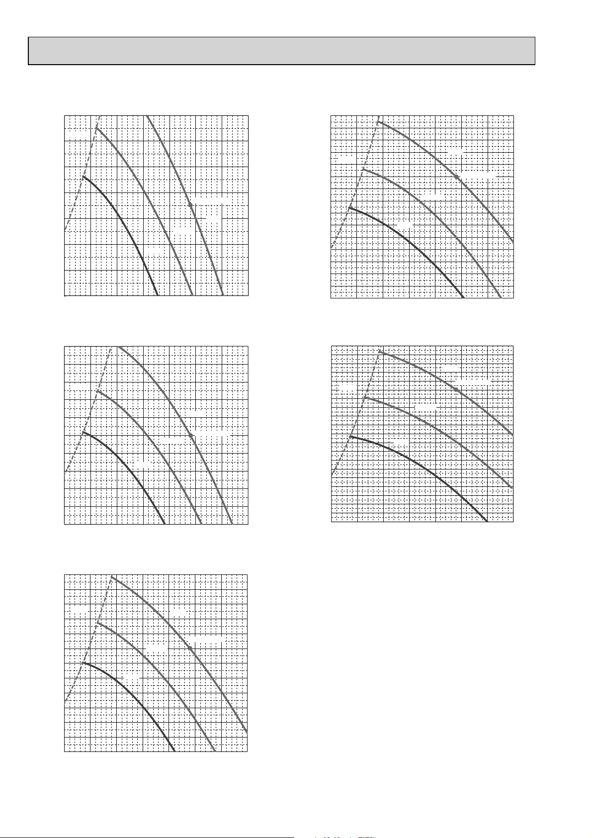
PEAD-RP100JA(L)
(External static pressure 35Pa) 220-240V 50Hz
70
Limit
60
50
40
30
20
External static pressure (Pa)
10
0
10 15 20 25 30 35 40 45
Low
Rated point
High
Middle
Airflow rate(m3/min)
PEAD-RP100JA(L)
(External static pressure 50Pa) 220-240V 50Hz
100
90
80
Limit
70
60
50
40
30
External static pressure (Pa)
20
10
0
10 15 20 25 30 35 40 45
Middle
Low
High
Rated point
Airflow rate(m3/min)
PEAD-RP100JA(L)
(External static pressure 70Pa) 220-240V 50Hz
120
110
100
Limit
90
80
70
60
50
40
External static pressure (Pa)
30
20
10
0
10 15 20 25 30 35 40 45
Low
Airflow rate(m3/min)
High
Rated point
Middle
PEAD-RP100JA(L)
(External static pressure 100Pa) 220-240V 50Hz
150
140
130
120
Limit
110
100
90
80
70
60
50
External static pressure (Pa)
40
30
20
10
0
10 15 20 25 30 35 40 45
Low
High
Rated point
Middle
Airflow rate(m3/min)
PEAD-RP100JA(L)
(External static pressure 150Pa) 220-240V 50Hz
200
190
180
170
160
150
140
130
120
110
100
External static pressure (Pa)
Limit
90
80
70
60
50
40
30
20
10
0
15 20 25 30 35 40 45
10
Low
Airflow rate(m3/min)
High
Rated point
Middle
96
Page 97
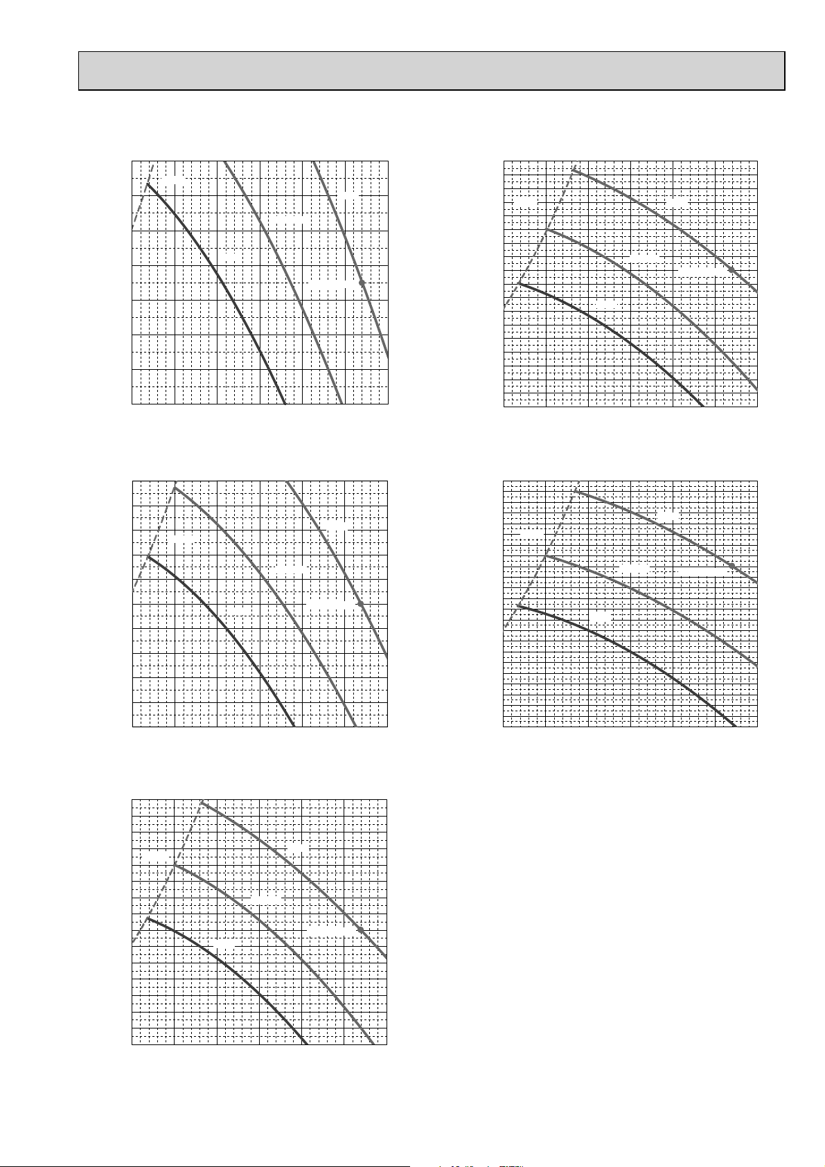
PEAD-RP125JA(L)
(External static pressure 35Pa) 220-240V 50Hz
70
Limit
60
50
40
30
20
External static pressure (Pa)
10
0
15 20 25 30 35 40 45
Low
Middle
High
Rated point
Airflow rate(m3/min)
PEAD-RP125JA(L)
(External static pressure 50Pa) 220-240V 50Hz
100
90
80
70
60
50
40
30
External static pressure (Pa)
20
10
0
15 20 25 30 35 40 45
Limit
Middle
Low
High
Rated point
Airflow rate(m3/min)
PEAD-RP125JA(L)
(External static pressure 70Pa) 220-240V 50Hz
150
140
130
120
Limit
110
100
90
80
70
60
50
40
External static pressure (Pa)
30
20
10
0
15 20 25 30 35 40 45
Low
Airflow rate(m3/min)
High
Middle
Rated point
PEAD-RP125JA(L)
(External static pressure 100Pa) 220-240V 50Hz
180
170
160
Limit
150
140
130
120
110
100
90
80
70
60
50
External static pressure (Pa)
40
30
20
10
0
15 20 25 30 35 40 45
Low
High
Middle
Rated point
Airflow rate(m3/min)
PEAD-RP125JA(L)
(External static pressure 150Pa) 220-240V 50Hz
230
220
210
200
190
180
170
160
150
140
130
120
110
100
External static pressure (Pa)
Limit
90
80
70
60
50
40
30
20
10
0
15
20 25 30 35 40 45
Low
Airflow rate(m3/min)
Middle
High
Rated point
97
Page 98
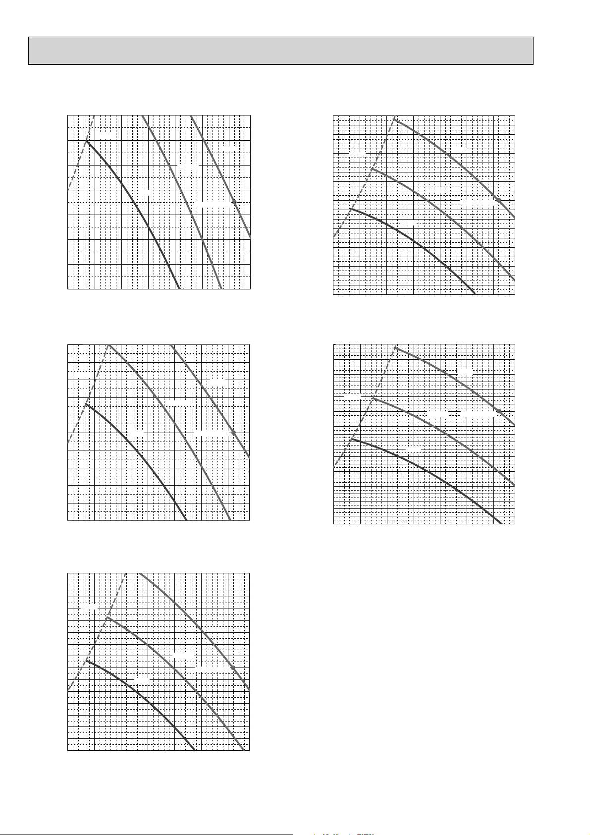
PEAD-RP140JA(L)
(External static pressure 35Pa) 220-240V 50Hz
70
60
50
40
30
20
External static pressure (Pa)
10
0
15 20 25 30 35 40 45
Limit
High
Middle
Low
Rated point
Airflow rate(m3/min)
PEAD-RP140JA(L)
(External static pressure 50Pa) 220-240V 50Hz
100
90
Limit
80
70
60
50
40
30
External static pressure (Pa)
20
10
0
15 20 25 30 35 40 5045
Low
Middle
High
Rated point
Airflow rate(m3/min)
PEAD-RP140JA(L)
(External static pressure 70Pa) 220-240V 50Hz
150
140
130
Limit
120
110
100
90
80
70
60
50
External static pressure (Pa)
40
30
20
10
0
15 20 25 30 35 40 45
Low
Middle
Airflow rate(m3/min)
High
Rated point
PEAD-RP140JA(L)
(External static pressure 100Pa) 220-240V 50Hz
190
180
170
160
150
140
130
120
110
100
External static pressure (Pa)
Limit
90
80
70
60
50
40
30
20
10
0
15 20 25 30 35 40 45
Low
High
Middle
Rated point
Airflow rate(m3/min)
PEAD-RP140JA(L)
(External static pressure 150Pa) 220-240V 50Hz
240
230
220
210
200
190
180
170
160
150
140
130
120
110
100
External static pressure (Pa)
Limit
Middle
90
80
70
60
50
40
30
20
10
0
20 25 30 35 40 45
15
Low
Airflow rate(m3/min)
High
Rated point
98
Page 99
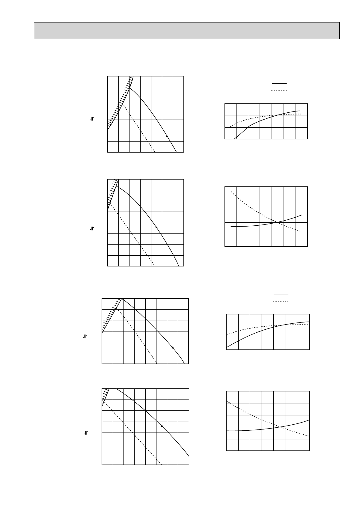
9-7. PEAD-RP·EA,EA2,GA
)
9-7-1. FAN PERFORMANCE AND CORRECTED AIR FLOW
PEAD-RP35EA2
PEAD-RP50EA
140
120
100
(1Pa 0.1mmAq)
External static pressure (Pa)
Fan Performance <30Pa>
80
60
40
20
6 8 10 12 14 16 18 20
Air Flow (CMM)
Corrected Air Flow
Cooling
1.1
1.0
0.9
0.8
Correction factor
810121416182022
Air flow (CMM)
Capacity
input
PEAD-RP60EA
160
140
120
100
(1Pa 0.1mmAq)
External static pressure (Pa)
120
100
80
60
40
(1Pa 0.1mmAq)
20
External static pressure (Pa)
140
120
100
80
60
40
(1Pa 0.1mmAq)
External static pressure (Pa)
20
Fan Performance <70Pa>
80
60
40
20
810121416182022
Air Flow (CMM)
Fan Performance <30Pa>
81012141618202224
Air Flow (CMM)
Fan Performance <70Pa>
10 12 14 16 18 20 22 24 26
Air Flow (CMM
Heating
1.3
1.2
1.1
1.0
Correction factor
0.9
0.8
810121416182022
Air flow (CMM)
Corrected Air Flow
Cooling
1.1
1.0
0.9
0.8
Correction factor
12 14 16 18 20 22 24 26
Air flow (CMM)
Heating
1.3
1.2
1.1
1.0
Correction factor
0.9
0.8
12 14 16 18 20 22 24 26
Air flow (CMM)
Capacity
input
99
Page 100
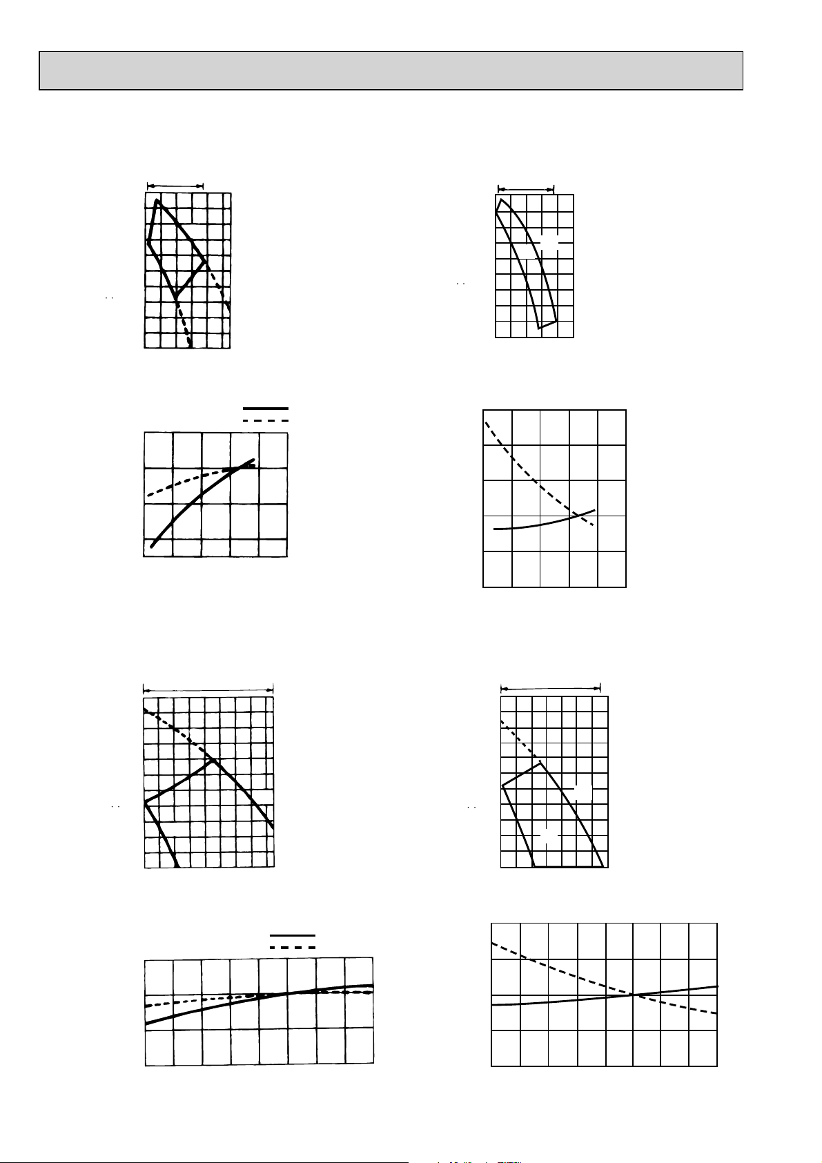
PEAD-RP71EA
Fan performance <130Pa>
Recommended range
200
180
160
140
120
100
80
=
60
40
(1Pa 0.1mmAq)
20
External static pressure (Pa)
12 16 20 24 28 32
Corrected Air Flow
1.1
1.0
0.9
Correction factor
0.8
12 16 20 24 28 32
PEAD-RP100EA2
PEAD-RP125EA
Lo
Air flow
Cooling
Air flow (CMM)
Hi
(CMM)
Capacity
Input
Fan performance <70Pa>
Recommended range
180
160
140
120
100
80
=
60
40
(1Pa 0.1mmAq)
20
External static pressure (Pa)
12 16 20 24 28 32
Air flow
Heating
1.3
1.2
1.1
1.0
Correction factor
0.9
0.8
12 16 20 24 28 32
Lo
Hi
(CMM)
Air flow (CMM)
Fan performance <130Pa>
Recommended range
220
200
180
160
140
120
100
80
=
60
(1Pa 0.1mmAq)
40
20
External static pressure (Pa)
Lo
32 34 36 38 40 42 44 46 48
Air flow
(CMM)
Hi
Corrected Air Flow
Cooling
1.1
1.0
0.9
Correction factor
0.8
32 34 36 38 40 42 44 46 48
Air flow (CMM)
Capacity
Input
Fan performance <70Pa>
Recommended range
220
200
180
160
140
120
100
80
=
60
(1Pa 0.1mmAq)
40
20
External static pressure (Pa)
32 34 36 38 40 42 44 46
Air flow
Heating
1.2
1.1
1.0
0.9
Correction factor
0.8
32 34 36 38 40 42 44 46 48
Hi
Lo
(CMM)
Air flow (CMM)
100
 Loading...