

Mitsubishi Electric PLA-RP60BA, PLA-RP50BA, PLA-RP35BA, PLA-RP71BA, PLA-RP100BA INSTALLATION MANUAL
...
Air-Conditioners
Кондиционеры
PLA-RP·BA Series
PLA-ZRP·BA Series
INSTALLATION MANUAL
For safe and correct use, read this manual and the outdoor unit installation manual thoroughly before installing
the air-conditioner unit.
INSTALLATIONSHANDBUCH
Aus Sicherheitsgründen und zur richtigen Anwendung vor Installation der Klimaanlage die vorliegende Bedienungsanleitung und das Installationshandbuch gründlich durchlesen.
MANUEL D’INSTALLATION
Avant d’installer le climatiseur, lire attentivement ce manuel, ainsi que le manuel d’installation de l’appareil extérieur pour une utilisation sûre et correct.
INSTALLATIEHANDLEIDING
Lees deze handleiding en de installatiehandleiding van het buitenapparaat zorgvuldig door voordat u met het
installeren van de airconditioner begint.
MANUAL DE INSTALACIÓN
Para un uso seguro y correcto, lea detalladamente este manual de instalación antes de montar la unidad de
aire acondicionado.
MANUALE DI INSTALLAZIONE
Per un uso sicuro e corretto, prima di installare il condizionatore d’aria leggere attentamente il presente manuale
ed il manuale d’installazione dell’unità esterna.
ΕΓΧΕΙΡΙΔΙΟ ΟΔΗΓΙΩΝ ΕΓΚΑΤΑΣΤΑΣΗΣ
Για σωστή και ασφαλή χρήση, διαβάστε προσεκτικά αυτό το εγχειρίδιο, καθώς και το εγχειρίδιο εγκατάστασης
της εξωτερικής μονάδας, πριν από την εγκατάσταση της μονάδας κλιματιστικού.
MANUAL DE INSTALAÇÃO
Para uma utilização segura e correcta, leia atentamente este manual e o manual de instalação da unidade exterior antes de instalar o aparelho de ar condicionado.
INSTALLATIONSMANUAL
Læs af sikkerhedshensyn denne manual samt manualen til installation af udendørsenheden grundigt, før du
installerer klimaanlægget.
INSTALLATIONSMANUAL
Läs bruksanvisningen och utomhusenhetens installationshandbok noga innan luftkonditioneringen installeras så
att den används på ett säkert och korrekt sätt.
MONTAJ ELKİTABI
Emniyetli ve doğru kullanım için, klima cihazını monte etmeden önce bu kılavuzu ve dış ünite montaj kılavuzunu
tamamıyla okuyun.
РУКОВОДСТВО ПО УСТАНОВКЕ
Для обеспечения безопасной и надлежащей эксплуатации внимательно прочтите данное руководство и
руководство по установке наружного прибора перед установкой кондиционера.
FOR INSTALLER
FÜR INSTALLATEURE
POUR L’INSTALLATEUR
VOOR DE INSTALLATEUR
PARA EL INSTALADOR
PER L’INSTALLATORE
ΓΙΑ ΑΥΤΟΝ ΠΟΥ ΚΑΝΕΙ ΤΗΝ ΕΓΚΑΤΑΣΤΑΣΗ
PARA O INSTALADOR
TIL INSTALLATØREN
FÖR INSTALLATÖREN
MONTÖR İÇİN
ДЛЯ УСТАНОВИТЕЛЯ
English
Deutsch
Français
Nederlands
Español
Italiano
Ελληνικά
Português
Dansk
Svenska
Türkçe
Русский

Contents
1. Safety precautions .....................................................................................2
2. Installation location .................................................................................... 3
3. Installing the indoor unit ............................................................................3
4. Installing the refrigerant piping .................................................................. 5
5. Drainage piping work .................................................................................6
6. Electrical work ...........................................................................................7
7. Test run .................................................................................................... 13
8. System control ........................................................................................16
9. Installing the grille ....................................................................................17
10. Easy maintenance function .....................................................................19
Note:
The phrase “Wired remote controller” in this installation manual refers only to the PAR-31MAA.
If you need any information for the other remote controller, please refer to either the installation manual or initial setting manual which are
included in these boxes.
1. Safety precautions
Before installing the unit, make sure you read all the “Safety precau-
►
tions”.
Please report to your supply authority or obtain their consent before
►
connecting this equipment to the power supply system.
Warning:
Describes precautions that must be observed to prevent danger of injury or
death to the user.
Caution:
Describes precautions that must be observed to prevent damage to the unit.
Warning:
• Ask a dealer or an authorized technician to install the unit.
•
The user should never attempt to repair the unit or transfer it to another location.
• For installation work, follow the instructions in the Installation Manual and use
tools and pipe components specifi cally made for use with refrigerant specifi ed
in the outdoor unit installation manual.
• The unit must be installed according to the instructions in order to minimize
the risk of damage from earthquakes, typhoons, or strong winds. An incorrectly installed unit may fall down and cause damage or injuries.
•
The unit must be securely installed on a structure that can sustain its weight.
• If the air conditioner is installed in a small room, measures must be taken to
prevent the refrigerant concentration in the room from exceeding the safety
limit in the event of refrigerant leakage. Should the refrigerant leak and cause
the concentration limit to be exceeded, hazards due to lack of oxygen in the
room may result.
• Ventilate the room if refrigerant leaks during operation. If refrigerant comes
into contact with a fl ame, poisonous gases will be released.
• All electric work must be performed by a qualifi ed technician according to lo-
cal regulations and the instructions given in this manual.
• Use only specifi ed cables for wiring. The wiring connections must be made
securely with no tension applied on the terminal connections. Also, never
splice the cables for wiring (unless otherwise indicated in this document).
Failure to observe these instructions may result in overheating or a fi re.
• The appliance shall be installed in accordance with national wiring regula-
tions.
After installation work has been completed, explain the “Safety Precautions,” use,
and maintenance of the unit to the customer according to the information in the
Operation Manual and perform the test run to ensure normal operation. Both the
Installation Manual and Operation Manual must be given to the user for keeping.
These manuals must be passed on to subsequent users.
: Indicates a part which must be grounded.
Warning:
Carefully read the labels affi xed to the main unit.
• This appliance is not intended for use by persons (including children) with
reduced physical, sensory or mental capabilities, or lack of experience and
knowledge, unless they have been given supervision or instruction concerning use of the appliance by a person responsible for their safety.
• Children should be supervised to ensure that they do not play with the appliance.
• The terminal block cover panel of the unit must be fi rmly attached.
• If the supply cord is damaged, it must be replaced by the manufacturer, its
service agent or similarly qualifi ed persons in order to avoid a hazard.
• Use only accessories authorized by Mitsubishi Electric and ask a dealer or an
authorized technician to install them.
• The user should never attempt to repair the unit or transfer it to another location.
• After installation has been completed, check for refrigerant leaks. If refrigerant leaks into the room and comes into contact with the fl ame of a heater or
portable cooking range, poisonous gases will be released.
• When installing or relocating, or servicing the air conditioner, use only the
specifi ed refrigerant (R410A) to charge the refrigerant lines. Do not mix it with
any other refrigerant and do not allow air to remain in the lines.
If air is mixed with the refrigerant, then it can be the cause of abnormal high pressure in the refrigerant line, and may result in an explosion and other hazards.
The use of any refrigerant other than that specifi ed for the system will cause
mechanical failure or system malfunction or unit breakdown. In the worst
case, this could lead to a serious impediment to securing product safety.
1.1. Before installation (Environment)
Caution:
• Do not use the unit in an unusual environment. If the air conditioner is installed in areas exposed to steam, volatile oil (including machine oil), or
sulfuric gas, areas exposed to high salt content such as the seaside, the performance can be signifi cantly reduced and the internal parts can be damaged.
• Do not install the unit where combustible gases may leak, be produced, fl ow,
or accumulate. If combustible gas accumulates around the unit, fi re or explo-
sion may result.
• Do not keep food, plants, caged pets, artwork, or precision instruments in the
direct airfl ow of the indoor unit or too close to the unit, as these items can be
damaged by temperature changes or dripping water.
1.2. Before installation or relocation
Caution:
• Be extremely careful when transporting the units. Two or more persons are
needed to handle the unit, as it weighs 20 kg or more. Do not grasp the packaging bands. Wear protective gloves as you can injure your hands on the fi ns
or other parts.
• Be sure to safely dispose of the packaging materials. Packaging materials,
such as nails and other metal or wooden parts may cause stabs or other injuries.
• Thermal insulation of the refrigerant pipe is necessary to prevent condensation. If the refrigerant pipe is not properly insulated, condensation will be
formed.
1.3. Before electric work
Caution:
• Be sure to install circuit breakers. If not installed, electric shock may result.
• For the power lines, use standard cables of suffi cient capacity. Otherwise, a
short circuit, overheating, or fi re may result.
• When installing the power lines, do not apply tension to the cables.
• Be sure to ground the unit. If the unit is not properly grounded, electric shock
may result.
1.4. Before starting the test run
Caution:
• Turn on the main power switch more than 12 hours before starting operation.
Starting operation just after turning on the power switch can severely damage
the internal parts.
• Before starting operation, check that all panels, guards and other protective
parts are correctly installed. Rotating, hot, or high voltage parts can cause
injuries.
• When the room humidity exceeds 80% or when the drainpipe is clogged, water may drip from the indoor unit. Do not install the indoor unit where such
dripping can cause damage.
• When installing the unit in a hospital or communications offi ce, be prepared
for noise and electronic interference. Inverters, home appliances, high-frequency medical equipment, and radio communications equipment can cause
the air conditioner to malfunction or breakdown. The air conditioner may
also affect medical equipment, disturbing medical care, and communications
equipment, harming the screen display quality.
• Place thermal insulation on the pipes to prevent condensation. If the drainpipe is installed incorrectly, water leakage and damage to the ceiling, fl oor,
furniture, or other possessions may result.
• Do not clean the air conditioner unit with water. Electric shock may result.
• Tighten all fl are nuts to specifi cation using a torque wrench. If tightened too
much, the fl are nut can break after an extended period.
• Use circuit breakers (ground fault interrupter, isolating switch (+B fuse), and
molded case circuit breaker) with the specifi ed capacity. If the circuit breaker
capacity is larger than the specifi ed capacity, breakdown or fi re may result.
• Do not operate the air conditioner without the air fi lter set in place. If the air
fi lter is not installed, dust may accumulate and breakdown may result.
• Do not touch any switch with wet hands. Electric shock may result.
• Do not touch the refrigerant pipes with bare hands during operation.
• After stopping operation, be sure to wait at least fi ve minutes before turning
off the main power switch. Otherwise, water leakage or breakdown may result.
2
2. Installation location
Refer to the outdoor unit installation manual.
3. Installing the indoor unit
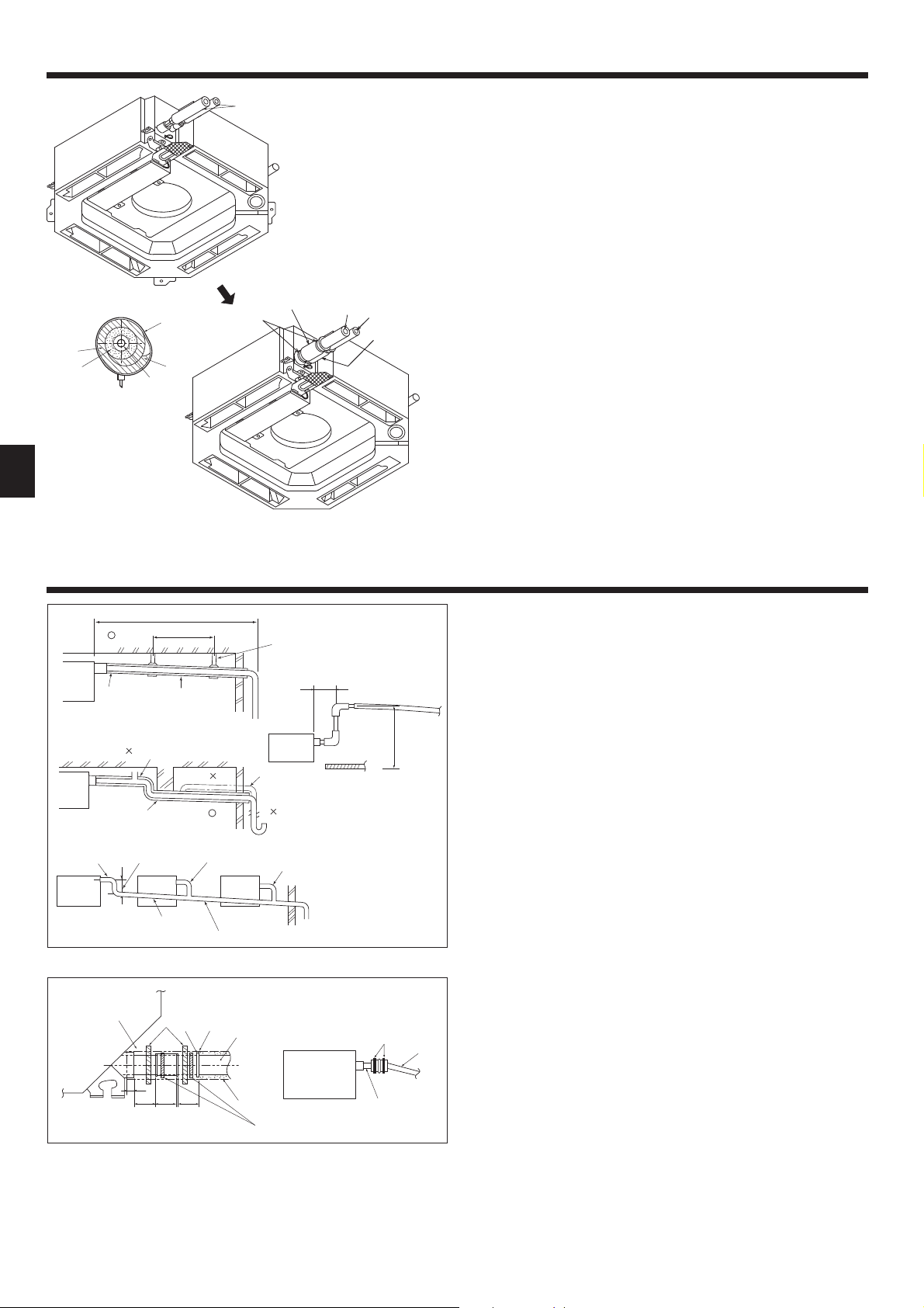
Fig. 3-1
950
20-45 20-45
160
160
840
150
90
187.5
135
+5
0
17
860-910
810
840
Min. 2500
20-45
(7.5)(7.5)
620
950
605
860-910
160
160
70
-
105
50
*
*
Min. 500
20-45
C
D
+5
0
35
17
Fig. 3-2
B
A
90
24
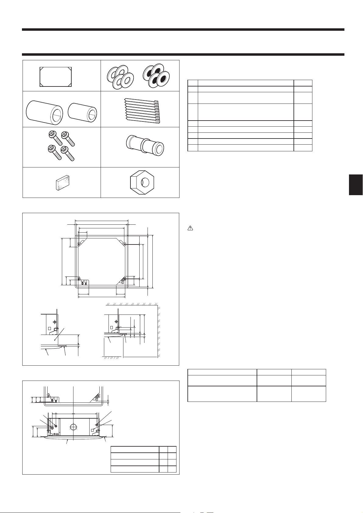
3.1. Check the indoor unit accessories (Fig. 3-1)
The indoor unit should be supplied with the following accessories.
Accessory name Q'ty
Installation template 1
1
Washers (with insulation)
2
Washers (without insulation)
4
4
Pipe cover (for refrigerant piping joint)
Small diameter
3
Large diameter
Band 8
4
Screw with washer (M5 × 25) for mounting grille 4
5
Drain socket 1
6
Insulation 1
7
Flare nut 1/4F(P60) 1
8
1
1
3.2. Ceiling openings and suspension bolt installation
locations (Fig. 3-2)
Caution:
Install the indoor unit at least 2.5m above fl oor or grade level.
For appliances not accessible to the general public.
• Using the installation template (top of the package) and the gauge (supplied as
an accessory with the grille), make an opening in the ceiling so that the main unit
can be installed as shown in the diagram. (The method for using the template
and the gauge is shown.)
* Before using, check the dimensions of template and gauge, because they
change due to fl uctuations of temperature and humidity.
* The dimensions of ceiling opening can be regulated within the range shown
in Fig.3-2; so center the main unit against the opening of ceiling, ensuring
that the respective opposite sides on all sides of the clearance between them
becomes identical.
• Use M10 (3/8") suspension bolts.
* Suspension bolts are to be procured at the fi eld.
• Install securely, ensuring that there is no clearance between the ceiling panel &
grille, and between the main unit & grille.
Outer side of main unit
A
Bolt pitch
B
Ceiling opening
C
Outer side of Grille
D
*Note that the space between ceiling panel of the unit and ceiling slab, etc. must be 10 to 15 mm.
When the optional multi-functional casement is installed, add 135 mm to the
*
dimensions marked on the fi gure.
Models C D
PLA-RP35/50/60/71BA(2)
PLA-ZRP35/50/60BA
PLA-RP100/125/140BA(2)
PLA-RP100BA3
PLA-ZRP71/100/125/140BA
Grille
E
Ceiling
F
Multi function casement (option)
G
Entire periphery
H
241 258
281 298
(mm)
170
60
284 377
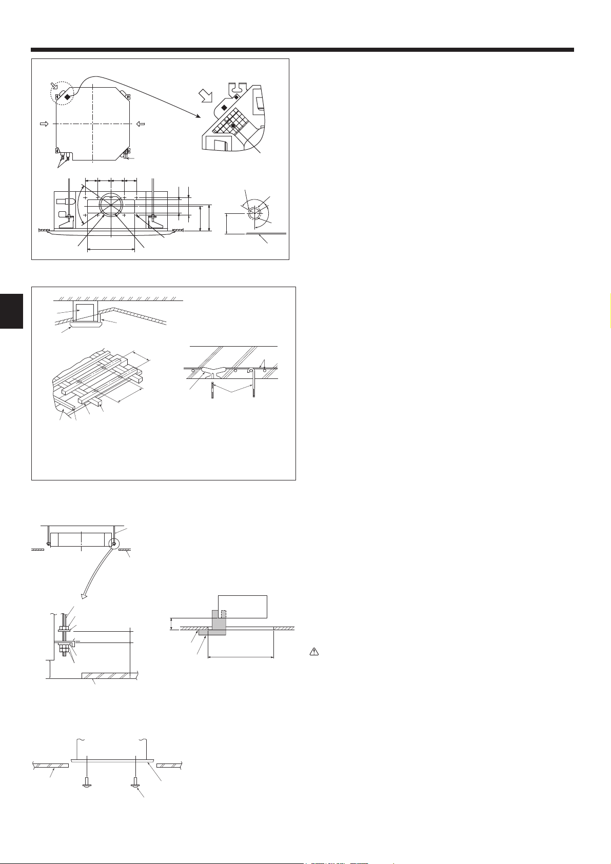
3.3. Refrigerant and drainage piping locations of
indoor unit
The fi gure marked with * in the drawing represent the dimensions of the main unit
140
*
*
190
*
(mm)
Models A B
(Z)RP35, 50 80 74
(Z)RP60 87 74
(Z)RP71, 100, 125, 140 85 77
Fig. 3-3
excluding those of the optional multi function casement. (Fig. 3-3)
Drain pipe
A
Ceiling
B
Grille
C
Refrigerant pipe (liquid)
D
Refrigerant pipe (gas)
E
Water supply inlet
F
Main unit
G
* When the optional multi-functional casement is installed, add 135 mm to the
dimensions marked on the fi gure.
3
3. Installing the indoor unit
100 100 90
90
70°
350
100
Fig. 3-4
Ceiling
D
Rafter
E
Beam
F
Roof beam
G
810
605
Use inserts rated at 100-150 kg each
H
(procure locally)
Suspension bolts M10(3/8”) (procure
I
locally)
Steel reinforcing rod
J
Fig. 3-5
"
A
B
C
*158
Unit
Grille
Pillar
120°
130
*155
*167
3.4. Branch duct hole and fresh air intake hole (Fig. 3-4)
At the time of installation, use the duct holes (cut out) located at the positions
shown in Fig3-4, as and when required.
• A fresh air intake hole for the optional multi function casement can also be made.
Note:
The fi gure marked with * in the drawing represent the dimensions of the main
unit excluding those of the optional multi function casement.
When installing the optional multi function casement, add 135 mm to the dimensions marked on the fi gure.
When installing the branch ducts, be sure to insulate adequately. Otherwise
#
condensation and dripping may occur.
When installing the fresh air intake hole, be sure to remove the insulator
P
that is pasted on the indoor unit.
Branch duct hole
A
Indoor unit
120°
!
B
Fresh air intake hole
C
Drain pipe
D
Refrigerant pipe
E
Branch duct hole diagram
F
(view from either side)
14-ø2.8 burring hole
G
ø150 cut out hole
H
ø175 burring hole pitch
I
Fresh air intake hole diagram
J
3-ø2.8 burring hole
K
ø125 burring hole pitch
L
ø100 cut out hole
M
Ceiling
N
Detailed fi gure of removing the insulator
O
Insulator
P
3.5. Suspension structure (Give site of suspension
strong structure) (Fig. 3-5)
• The ceiling work differs according to the construction of the building. Building
constructors and interior decorators should be consulted for details.
(1) Extent of ceiling removal: The ceiling must be kept completely horizontal and
the ceiling foundation (framework: wooden slats and slat holders) must be reinforced in order to protect the ceiling from vibration.
(2) Cut and remove the ceiling foundation.
(3) Reinforce the ends of the ceiling foundation where it has been cut and add ceil-
ing foundation for securing the ends of the ceiling board.
(4) When installing the indoor unit on a slanted ceiling, attach a pillar between the
ceiling and the grille and set so that the unit is installed horizontally.
Wooden structures
1
• Use tie beams (single storied houses) or second fl oor beams (2 story houses) as
reinforcing members.
• Wooden beams for suspending air conditioners must be sturdy and their sides
must be at least 6 cm long if the beams are separated by not more than 90 cm
and their sides must be at least 9 cm long if the beams are separated by as much
as 180 cm. The size of the suspension bolts should be ø10 (3/8"). (The bolts do
not come with the unit.)
Ferro-concrete structures
2
Secure the suspension bolts using the method shown, or use steel or wooden
hangers, etc. to install the suspension bolts.
Suspension bolt
A
Ceiling
B
Nut
C
Washer (with insulation)
D
Mounting plate
E
Washer (without insulation)
F
Check using the Installation gauge
G
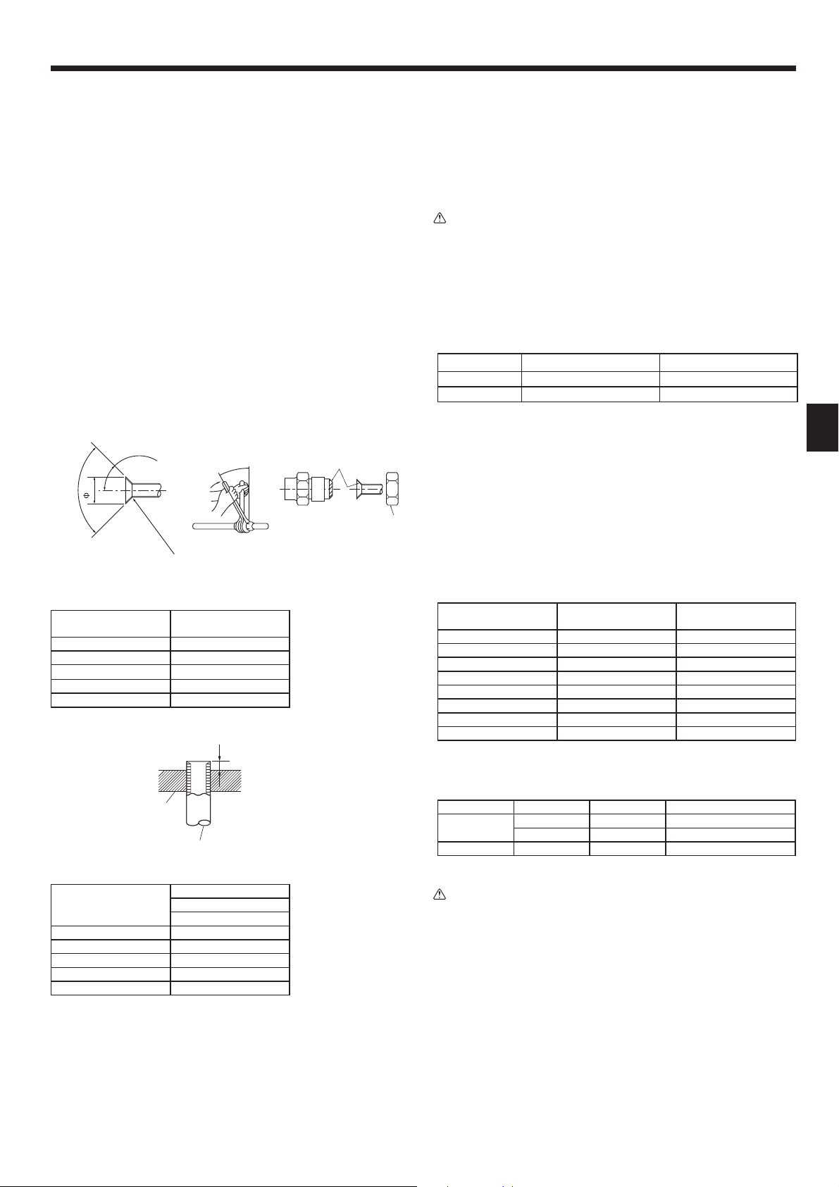
Suspend the main unit as shown in the diagram.
Figures given in parentheses represent the dimensions in case of installing optional
multi function casement.
1. In advance, set the parts onto the suspension bolts in the order of the washers
(with insulation), washers (without insulation) and nuts (double).
• Fit the washer with cushion so that the insulation faces downward.
• In case of using upper washers to suspend the main unit, the lower washers (with
insulation) and nuts (double) are to be set later.
2. Lift the unit to the proper height of the suspension bolts to insert the mounting
plate between washers and then fasten it securely.
3. When the main unit cannot be aligned against the mounting hole on the ceiling,
it is adjustable owing to a slot provided on the mounting plate.
• Make sure that A is performed within 17-22 mm. Damage could result by failing
to adhere to this range. (Fig. 3-7)
Caution:
Use the top half of the box as a protective cover to prevent dust or debris
from getting inside the unit prior to installation of the decorative cover or
when applying ceiling materials.
3.7. Confi rming the position of main unit and
tightening the suspension bolts (Fig. 3-8)
• Using the gauge attached to the grille, ensure that the bottom of the main unit is
+5
0
17
Fig. 3-6
Min. 30
)
240
(
105
+5
A=17
0
Main unit
A
Ceiling
B
Gauge
C
Ceiling opening dimensions
D
Fig. 3-7
properly aligned with the opening of the ceiling. Be sure to confi rm this, otherwise
Main unit
A
Ceiling
B
Installation template
C
(Top of the package)
Screw with washer (accessory)
D
Fig. 3-8
condensation may form and drip due to air leakage, etc.
• Confi rm that the main unit is horizontally levelled, using a level or a vinyl tube
fi lled with water.
• After checking the position of the main unit, tighten the nuts of the suspension
bolts securely to fasten the main unit.
• The installation template (top of the package) can be used as a protective sheet
to prevent dust from entering the main unit when the grilles are left unattached for
a while or when the ceiling materials are to be lined after installation of the unit is
fi nished.
* As for the details of fi tting, refer to the instructions given on the Installation tem-
plate.
4
3.6. Unit suspension procedures (Fig. 3-6)
4. Installing the refrigerant piping
4.1. Precautions
For devices that use R410A refrigerant
• Use ester oil, ether oil or alkylbenzene oil (small amount) as the refrigeration oil applied to the fl ared sections.
• Use C1220 copper phosphorus for copper and copper alloy seamless
pipes, to connect the refrigerant pipes. Use refrigerant pipes with the thicknesses specifi ed in the table below. Make sure the insides of the pipes are
clean and do not contain any harmful contaminants such as sulfuric compounds, oxidants, debris, or dust.
Warning:
When installing or relocating, or servicing the air conditioner, use only the
specifi ed refrigerant (R410A) to charge the refrigerant lines. Do not mix it
with any other refrigerant and do not allow air to remain in the lines.
If air is mixed with the refrigerant, then it can be the cause of abnormal high
pressure in the refrigerant line, and may result in an explosion and other hazards.
The use of any refrigerant other than that specifi ed for the system will cause
mechanical failure or system malfunction or unit breakdown. In the worst
case, this could lead to a serious impediment to securing product safety.
(Z)RP35, 50 (Z)RP60-140
Liquid pipe
Gas pipe
• Do not use pipes thinner than those specifi ed above.
[
6.35 thickness 0.8 mm
[
12.7 thickness 0.8 mm
[
9.52 thickness 0.8 mm
[
15.88 thickness 1.0 mm
45°± 2°
A
90°± 0.5°
R0.4 - R0.8
Fig. 4-1
Flare cutting dimensions
A
Copper pipe O.D.
(mm)
[
6.35 8.7 - 9.1
[
9.52 12.8 - 13.2
[
12.7 16.2 - 16.6
[
15.88 19.3 - 19.7
[
19.05 23.6 - 24.0
Flare dimensions
[
A dimensions (mm)
B
Die
E
Copper pipe
F
Fig. 4-2
4.2. Connecting pipes (Fig. 4-1)
• When commercially available copper pipes are used, wrap liquid and gas pipes
with commercially available insulation materials (heat-resistant to 100 °C or
more, thickness of 12 mm or more).
• The indoor parts of the drain pipe should be wrapped with polyethylene foam in-
sulation materials (specifi c gravity of 0.03, thickness of 9 mm or more).
• Apply thin layer of refrigerant oil to pipe and joint seating surface before tighten-
ing fl are nut.
• Use 2 wrenches to tighten piping connections.
• Use refrigerant piping insulation provided to insulate indoor unit connections. In-
sulate carefully.
Flare nut tightening torque
B
Copper pipe O.D.
(mm)
[
6.35 17 14-18
[
6.35 22 34-42
[
9.52 22 34-42
[
12.7 26 49-61
[
12.7 29 68-82
[
15.88 29 68-82
[
15.88 36 100-120
[
19.05 36 100-120
Apply refrigerating machine oil over the entire fl are seat surface.
C
Use correct fl are nuts meeting the pipe size of the outdoor unit.
D
Available pipe size
(Z)RP35, 50 (Z)RP60 (Z)RP71-140
[
Liquid side
Gas side
Ο : Factory fl are nut attachment to the heat exchanger.
6.35 Ο
[
12.7 Ο
—
Flare nut O.D.
(mm)
[
6.35 —
[
9.52 Ο
[
15.88 Ο
Tightening torque
(N·m)
[
9.52 Ο
[
15.88 Ο
Copper pipe O.D.
(mm)
[
6.35 (1/4”) 0 - 0.5
[
9.52 (3/8”) 0 - 0.5
[
12.7 (1/2”) 0 - 0.5
[
15.88 (5/8”) 0 - 0.5
[
19.05 (3/4”) 0 - 0.5
Flare tool for R410A
B (mm)
Clutch type
Warning:
When installing the unit, securely connect the refrigerant pipes before starting the compressor.
5
4. Installing the refrigerant piping
,
Refrigerant pipe and
A
insulating material
Pipe cover (large)
B
Pipe cover (small)
C
Refrigerant pipe (gas)
D
Refrigerant pipe (liquid)
E
Band
F
Cross-sectional view of
G
connection
Pipe
H
Insulating material
I
Squeeze
J
4.3. Indoor unit (Fig. 4-3)
Heat insulation for refrigerant pipes:
1 Wrap the enclosed large-sized pipe cover around the gas pipe, making sure
that the end of the pipe cover touches the side of the unit.
2 Wrap the enclosed small-sized pipe cover around the liquid pipe, making sure
that the end of the pipe cover touches the side of the unit.
3 Secure both ends of each pipe cover with the enclosed bands. (Attach the
bands 20 mm from the ends of the pipe cover.)
• After connecting the refrigerant piping to the indoor unit, be sure to test the pipe
connections for gas leakage with nitrogen gas. (Check that there is no refrigerant
leakage from the refrigerant piping to the indoor unit.)
4.4. For twin/triple combination
Refer to the outdoor unit installation manual.
Fig. 4-3
5. Drainage piping work
Max. 20 m
1.5 - 2 m
11
25 25 25
Fig. 5-1
(mm)
5.1. Drainage piping work (Fig. 5-1)
• Use VP25 (O.D. ø32 PVC TUBE) for drain piping and provide 1/100 or more
Max. 15 cm
downward slope.
• Be sure to connect the piping joints using a polyvinyl type adhesive.
• Observe the fi gure for piping work.
• Use the included drain hose to change the extraction direction.
Correct piping
1
Wrong piping
2
Insulation (9 mm or more)
A
Downward slope (1/100 or more)
B
Grouped piping
O.D. ø32 PVC TUBE
D
Make it as large as possible
E
Indoor unit
F
Make the piping size large for grouped
G
piping.
1.Connect the drain socket (supplied with the unit) to the drain port. (Fig. 5-2)
(Fix the tube using PVC adhesive then secure it with a band.)
2.Install a locally purchased drain pipe (PVC pipe, O.D. ø32).
(Fix the pipe using PVC adhesive then secure it with a band.)
3.Insulate the tube and pipe. (PVC pipe, O.D. ø32 and socket)
4.Check that drain fl ows smoothly.
5.Insulate the drain port with insulating material, then secure the material with a
band. (Both insulating material and band are supplied with the unit.)
Unit
A
Insulating material
B
Band
C
Drain port (transparent)
D
Insertion margin
E
Matching
F
Drain pipe (O.D. ø32 PVC TUBE)
G
Insulating material (purchased locally)
H
Transparent PVC pipe
I
O.D. ø32 PVC TUBE(Slope 1/100 or more)
J
Drain socket
K
Support metal
C
Air bleeder
K
Raised
L
Odor trap
M
Downward slope (1/100 or more)
H
O.D. ø38 PVC TUBE for grouped piping.
I
(9 mm or more insulation)
Up to 85 cm
J
Fig. 5-2
6
6. Electrical work
S1
S2
L
N
1
2
S1
S2
S3
S3
AB C
D
E
F
G
S1
S2
L
N
1
2
S1
S2
S3
1
2
S1
S2
S3
S3
1
2
S1
S2
S3
1
2
S1
S2
S3
ABC
D
E
F
GGGG
H
H
H
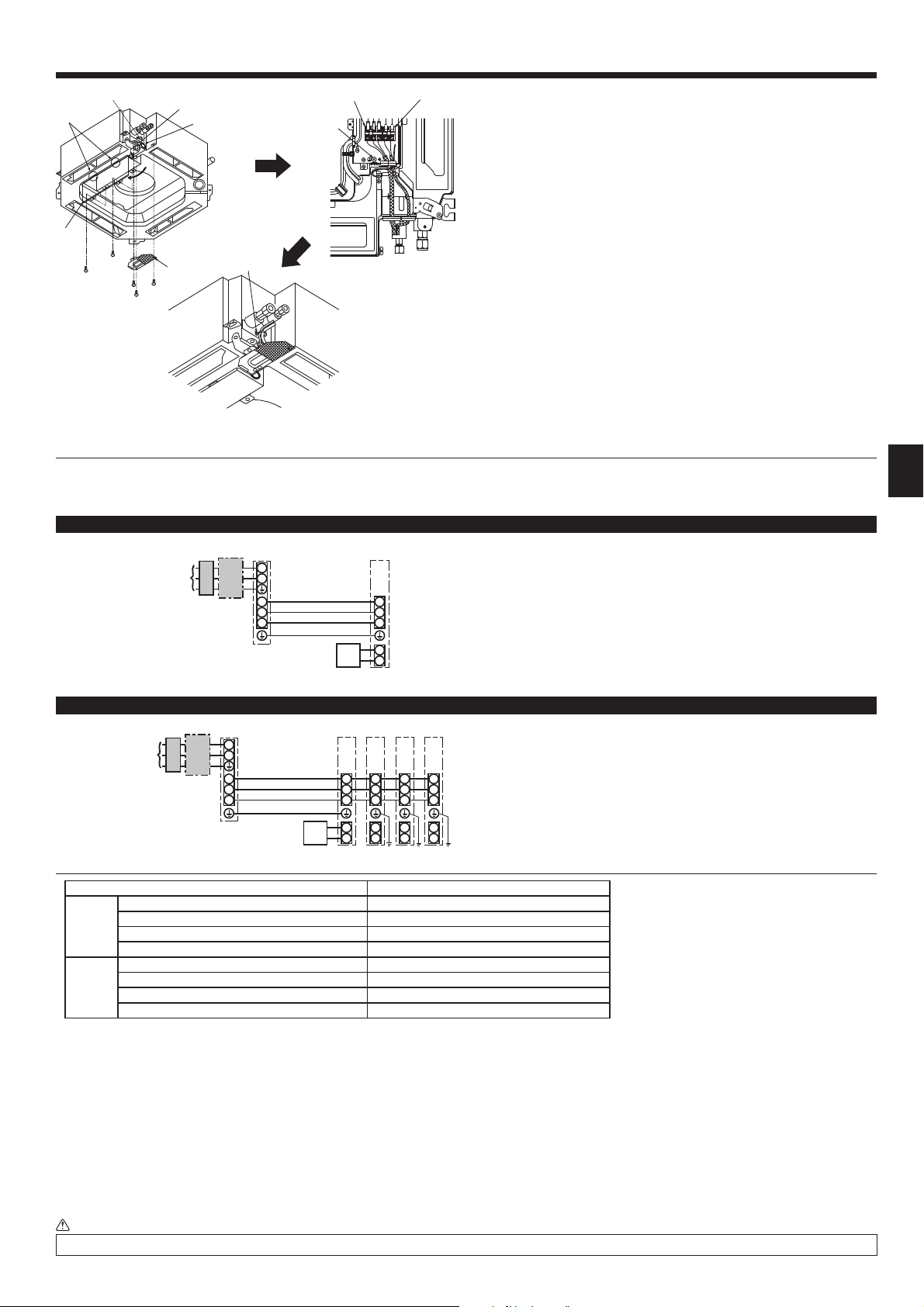
Fig. 6-1
6.1.1. Indoor unit power supplied from outdoor unit
The following connection patterns are available.
The outdoor unit power supply patterns vary on models.
1 System
1:1 System
6.1. Indoor unit (Fig. 6-1)
1. Remove the electrical wiring service panel.
2. Remove the electrical box cover.
3. Wire the power cable and control cable separately through the respective wiring
entries given in the diagram.
• Do not allow slackening of the terminal screws
• Leave excess cable so that the electrical box cover can be suspended below the
unit during servicing. (Approx. 50 to 100 mm)
Entry for control cable
A
Entry for power
B
Clamp
C
Electrical box cover
D
Service panel for electrical wiring
E
Temporary hook for electrical box cover
F
Indoor / Outdoor unit connecting terminals
G
Remote controller connector
H
Secure with the clamp
I
Earth terminal
J
.
* Affi x label A that is included with the manuals near each wiring diagram for the indoor and outdoor units.
* Affi x label A that is included with the manuals near each wiring diagram for the indoor and outdoor units.
*1. <For 35-140 outdoor unit application>
Max. 45 m
If 2.5 mm
If 2.5 mm
<For 200/250 outdoor unit application>
Max. 18 m
If 2.5 mm
If 4 mm
If 6 mm
*2. The 10 m wire is attached in the remote controller accessory. Max. 500 m
*3. The fi gures are NOT always against the ground.
S3 terminal has 24 V DC against S2 terminal. However between S3 and S1, these terminals are not electrically insulated by the transformer or other device.
Notes: 1. Wiring size must comply with the applicable local and national code.
2.
3. Install an earth longer than other cables.
Never splice the power cable or the indoor-outdoor connection cable, otherwise it may result in a smoke, a fi re or communication failure.
A Outdoor unit power supply
B Earth leakage breaker
C Wiring circuit breaker or isolating switch
D Outdoor unit
E Indoor unit/outdoor unit connecting cables
F Remote controller
G Indoor unit
Simultaneous twin/triple/quadruple system
A Outdoor unit power supply
B Earth leakage breaker
C Wiring circuit breaker or isolating switch
D Outdoor unit
E Indoor unit/outdoor unit connecting cables
F Remote controller
G Indoor unit
H Indoor unit earth
Indoor unit model PLA
Warning:
Indoor unit-Outdoor unit *1 3 × 1.5 (polar)
)
Indoor unit-Outdoor unit earth *1 1 × Min. 1.5
e
(
Indoor unit earth 1 × Min. 1.5
Wiring
Remote controller-Indoor unit *2 2 × 0.3 (Non-polar)
Wire No. × size
Indoor unit (Heater) L-N *3 —
Indoor unit-Outdoor unit S1-S2 *3 230 V AC
Indoor unit-Outdoor unit S2-S3 *3 24 V DC
rating
Circuit
Remote controller-Indoor unit *3 12 V DC
2
used, Max. 50 m
2
used and S3 separated, Max. 80 m
2
used, Max. 30 m
2
used and S3 separated, Max. 50 m
2
used and S3 separated, Max. 80 m
Power supply cords and indoor unit/outdoor unit connecting cords shall not be lighter than polychloroprene sheathed fl exible cord. (Design 60245 IEC 57)
7
S1
S2
S3
L
N
BLUE
BLUE
YELLOW
YELLOW
CN01
CN01
BLACK
CN01
BLACK
S1
S2
S3
L
N
YELLOW
BLUE
BLUE
YELLOW
CN01
6. Electrical work
S1
S2
L
N
1
2
L
N
S1
S2
S3
1
2
L
N
S1
S2
S3
1
2
L
N
S1
S2
S3
1
2
L
N
S1
S2
S3
S3
AB C
D
E
JBC
F
H
GGGG
K
K
K
H
H
H
ON
OFF 1 2
(SW8)
3
S1
S2
L
N
1
2
L
N
S1
S2
S3
S3
A
CB
D
JEB
C
F
G
H
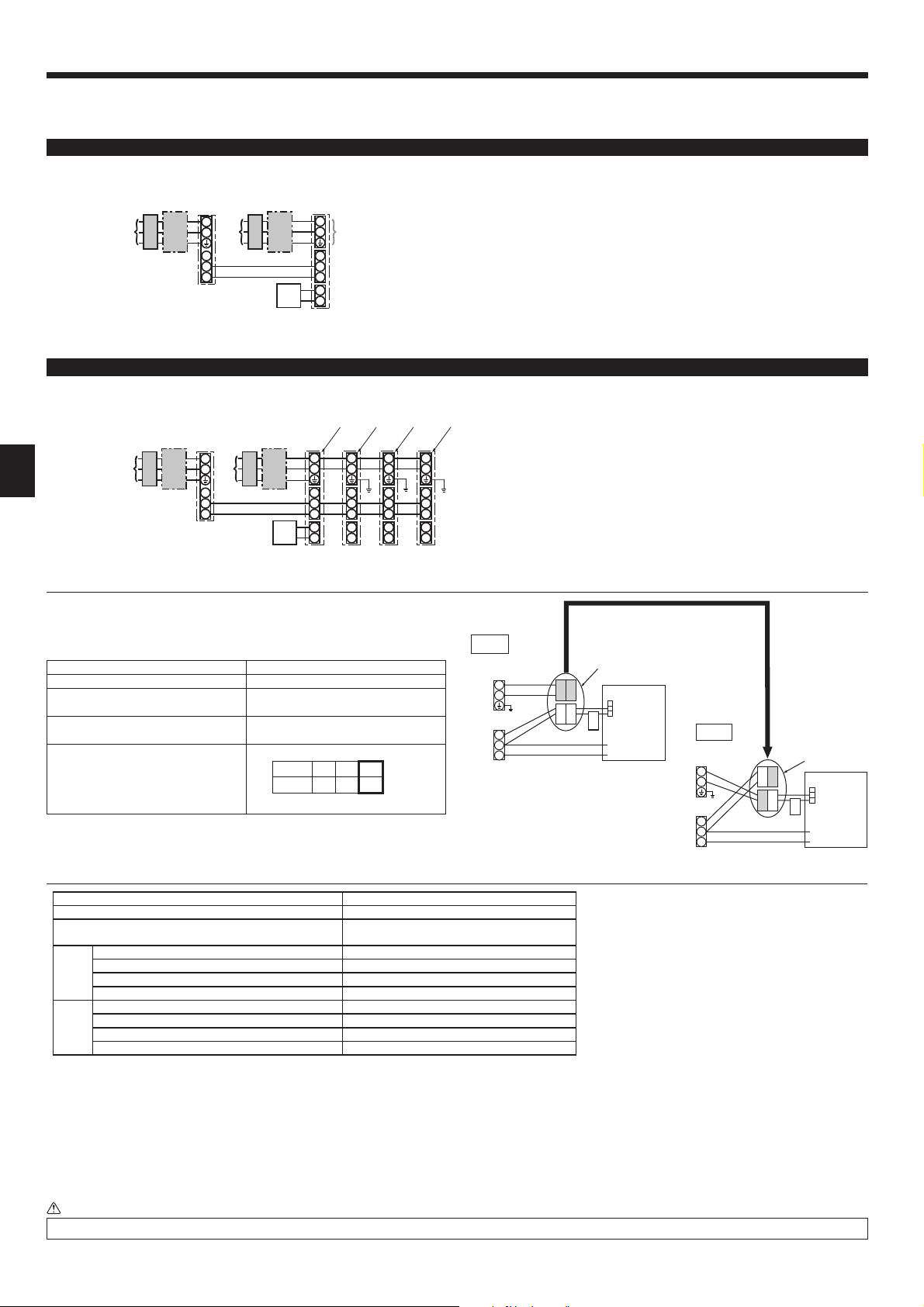
6.1.2. Separate indoor unit/outdoor unit power supplies (For PUHZ application only)
The following connection patterns are available.
The outdoor unit power supply patterns vary on models.
1:1 System
1:1 System
* The indoor power supply terminal kit is required.
A Outdoor unit power supply
B Earth leakage breaker
C Wiring circuit breaker or isolating switch
D Outdoor unit
E Indoor unit/outdoor unit connecting cables
F Remote controller
G Indoor unit
H Option
J Indoor unit power supply
* Affi x label B that is included with the manuals near each wiring diagram for the indoor and outdoor units.
Simultaneous twin/triple/quadruple system
* The indoor power supply terminal kits are required.
* Affi x label B that is included with the manuals near each wiring diagram for the indoor and outdoor units.
If the indoor and outdoor units have separate power supplies, refer to the table
below. If the indoor power supply terminal kit is used, change the indoor unit electrical box wiring refering to the fi gure in the right and the DIP switch settings of the
outdoor unit control board.
Indoor unit specifi cations
Indoor power supply terminal kit (option)
Indoor unit electrical box connector
connection change
Label affi xed near each wiring diagram
for the indoor and outdoor units
Required
Required
Required
Outdoor unit DIP switch settings (when
using separate indoor unit/outdoor unit
power supplies only)
Set the SW8-3 to ON.
* There are 3 types of labels (labels A, B and C). Affi x the appropriate labels to the
units according to the wiring method.
A Outdoor unit power supply
B Earth leakage breaker
C Wiring circuit breaker or isolating switch
D Outdoor unit
E Indoor unit/outdoor unit connecting cables
F Remote controller
G Indoor unit
H Option
J Indoor unit power supply
K Indoor unit earth
Option
Indoor unit power supplied from outdoor unit
(initial setting)
Connectors (connections of initial setting
are for indoor unit power supplied from
outdoor unit)
Indoor unit
control board
Option
Separate indoor unit/outdoor unit power supplies
If the indoor and
outdoor units have
separate power
supplies, change the
connections of the
connectors as shown
in the following
fi gure.
Connectors
Indoor unit
control board
Indoor unit model PLA
Indoor unit power supply ~/N (single), 50 Hz, 230 V
Indoor unit input capacity
Main switch (Breaker)
)
Indoor unit power supply & earth 3 × Min. 1.5
2
Indoor unit-Outdoor unit *2 2 × Min. 0.3
Indoor unit-Outdoor unit earth –
Wiring
size (mm
Wire No. ×
Remote controller-Indoor unit *3 2 × 0.3 (Non-polar)
*1
Indoor unit L-N *4 230 V AC
Indoor unit-Outdoor unit S1-S2 *4 –
Indoor unit-Outdoor unit S2-S3 *4 24 V DC
rating
Circuit
Remote controller-Indoor unit *4 12 V DC
*1. A breaker with at least 3.0 mm contact separation in each pole shall be provided. Use earth leakage breaker (NV).
The breaker shall be provided to ensure disconnection of all active phase conductors of the supply.
*2. Max. 120 m
*3. The 10 m wire is attached in the remote controller accessory. Max. 500 m
*4. The fi gures are NOT always against the ground.
Notes: 1. Wiring size must comply with the applicable local and national code.
2.
3. Install an earth longer than other cables.
Never splice the power cable or the indoor-outdoor connection cable, otherwise it may result in a smoke, a fi re or communication failure.
Power supply cords and indoor unit/outdoor unit connecting cords shall not be lighter than polychloroprene sheathed fl exible cord.
(Design 60245 IEC 57)
Warning:
8
16 A
6. Electrical work
min
MODEL SELECT
ON/OFF TEMP
FAN
VANE
MODE
CHECK
LOUVER
TEST RUN
RESETSET CLOCK
Fig. 6-2
MODEL SELECT
ON/OFF TEMP
FAN
VANE
MODE
CHECK
LOUVER
TEST RUN
RESETSET CLOCK
Fig. 6-3
MODEL SELECT
ON/OFF TEMP
FAN
VANE
MODE
LOUVER
CHECK
TEST RUN
RESETSET CLOCK
AUTO STOP
AUTO START
h
min
AUTO STOP
AUTO START
h
min
AUTO STOP
AUTO START
h
min
6.2. Remote controller
6.2.1. For wired remote controller
1) 2 remote controllers setting
If 2 remote controllers are connected, set one to “Main” and the other to “Sub”. For
setting procedures, refer to “Function selection of remote controller” in the opera-
tion manual for the indoor unit.
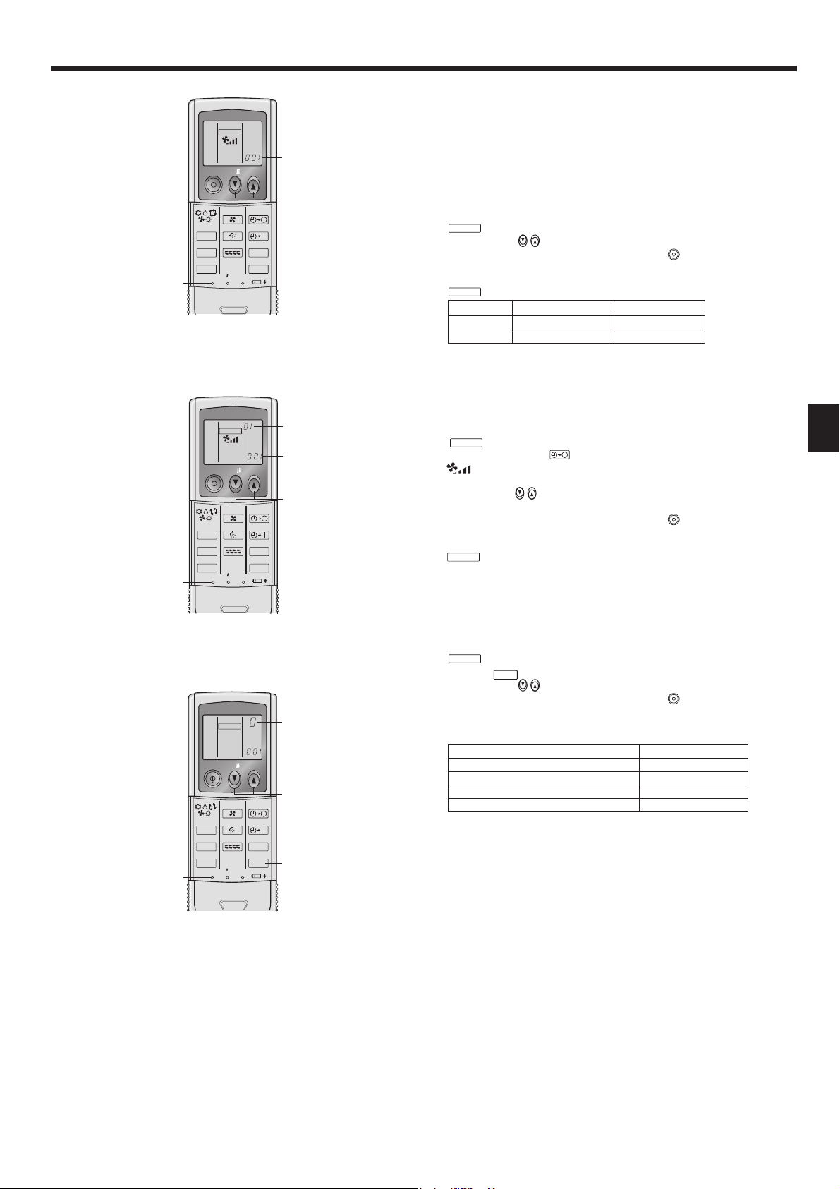
6.2.2. For wireless remote controller
1) Setting (Fig. 6-2)
Insert batteries.
1
Press the SET button with something sharp at the end.
2
MODEL SELECT
3
4
2) Automatic fan speed setting (Fig. 6-3)
1. Press the SET button with something sharp at the end.
2. Press the AUTO STOP
3. Press the temp.
(Setting No.02:with automatic fan speed )
4. Press the SET button with something sharp at the end.
3) Assigning a remote controller to each unit (Fig. 6-4)
Each unit can be operated only by the assigned remote controller.
Make sure each pair of an indoor unit PC board and a remote controller is assigned
to the same pair No.
4) Wireless remote controller pair number setting operation
1
Start this operation from the status of remote controller display turned off.
2
3
4
Set pair number is lighted for 3 seconds then turned off.
blinks and Model No. is lighted.
Press the temp
If you mistook the operation, press the ON/OFF
buttons to set the Model No.
button and operate again
from procedure 2.
Press the SET button with something sharp at the end.
and Model No. are lighted for 3 seconds, then turned off.
MODEL SELECT
Indoor Outdoor
PLA
PUH, PUHZ, SUZ 001
PU 033
Model No.
A
It is necessary to set for wireless remote controller only when automatic fan
speed is not set at initial setting.
It is not necessary to set for wired remote controller with automatic fan speed at
initial setting.
Operate when display of remote controller is off.
MODEL SELECT
blinks and Model No. is lighted A.
button.
blinks and setting No. is lighted B.
(Setting No.01: without automatic fan speed )
buttons to set the setting No.02.
If you mistook the operation, press the ON/OFF
button and operate again
from procedure 2.
MODEL SELECT
and Model No. are lighted for 3 seconds, then turned off.
Press the SET button with something sharp at the end.
MODEL SELECT
blinks and Model No. is lighted.
Press the
Press the temp
If you mistook the operation, press the ON/OFF
button twice continuously. Pair No. “0” blinks.
buttons to set the pair number you want to set.
button and operate again
from procedure 2.
Press the SET button with something sharp at the end.
Pair No. of wireless remote controller Indoor PC board
A
0 Initial setting
1 Cut J41
2 Cut J42
3-9 Cut J41, J42
Fig. 6-4
9
6. Electrical work
Service menu
Test run
Input maintenance info.
Function setting
Check
Self check
Main menu:
Cursor
F1 F2 F3 F4
Fig. 6-5 Fig. 6-6
Function setting
Ref. address
Mode 1
Mode 2
Mode 3
Mode 4
Request:
Cursor Cursor
F1 F2 F3 F4
Grp.
Fig. 6-7 Fig. 6-8
Function setting
Ref. address
Grp.
Function setting
Ref. address
Unit No.
Monitor:
Cursor Address
Grp./1/2/3/4/All
F1 F2 F3 F4
Function setting
Ref. address
Mode 7
Mode 8
Mode 9
Mode 10
Request:
Cursor Cursor
Unit # 1
F1 F2 F3 F4
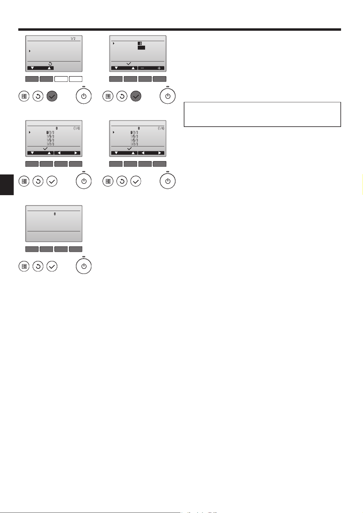
6.3. Function settings
6.3.1. Function setting on the unit (Selecting the unit functions)
1) For wired remote controller
(Fig. 6-5)
1
• Select “Service” from the Main menu, and press the [SELECT] button.
• Select “Function settings” with the [F1] or [F2] button, and press the [SELECT]
button.
(Fig. 6-6)
2
• Set the indoor unit refrigerant addresses and unit numbers with the [F1]
through [F4] buttons, and then press the [SELECT] button to confi rm the cur-
rent setting.
<Checking the Indoor unit No.>
When the [SELECT] button is pressed, the target indoor unit will start fan operation. If the unit is common or when running all units, all indoor units for the selected refrigerant address will start fan operation.
(Fig. 6-7)
3
• When data collection from the indoor units is completed, the current settings
appears highlighted. Non-highlighted items indicate that no function settings
are made. Screen appearance varies depending on the “Unit No.” setting.
(Fig. 6-8)
4
• Use the [F1] or [F2] button to move the cursor to select the mode number, and
change the setting number with the [F3] or [F4] button.
(Fig. 6-9)
5
• When the settings are completed, press the [SELECT] button to send the setting data from the remote controller to the indoor units.
• When the transmission is successfully completed, the screen will return to the
Function setting screen.
Sending data
F1 F2 F3 F4
Fig. 6-9
10
6. Electrical work
CHECK
CHECK
h
min
h
h
CHECK
ON/OFF TEMP
AUTO STOP
AUTO START
h
min
FAN
VANE
MODE
LOUVER
CHECK
TEST RUN
RESETSET CLOCK
CHECK
CHECKCHECK
CHECK
Fig. 6-10
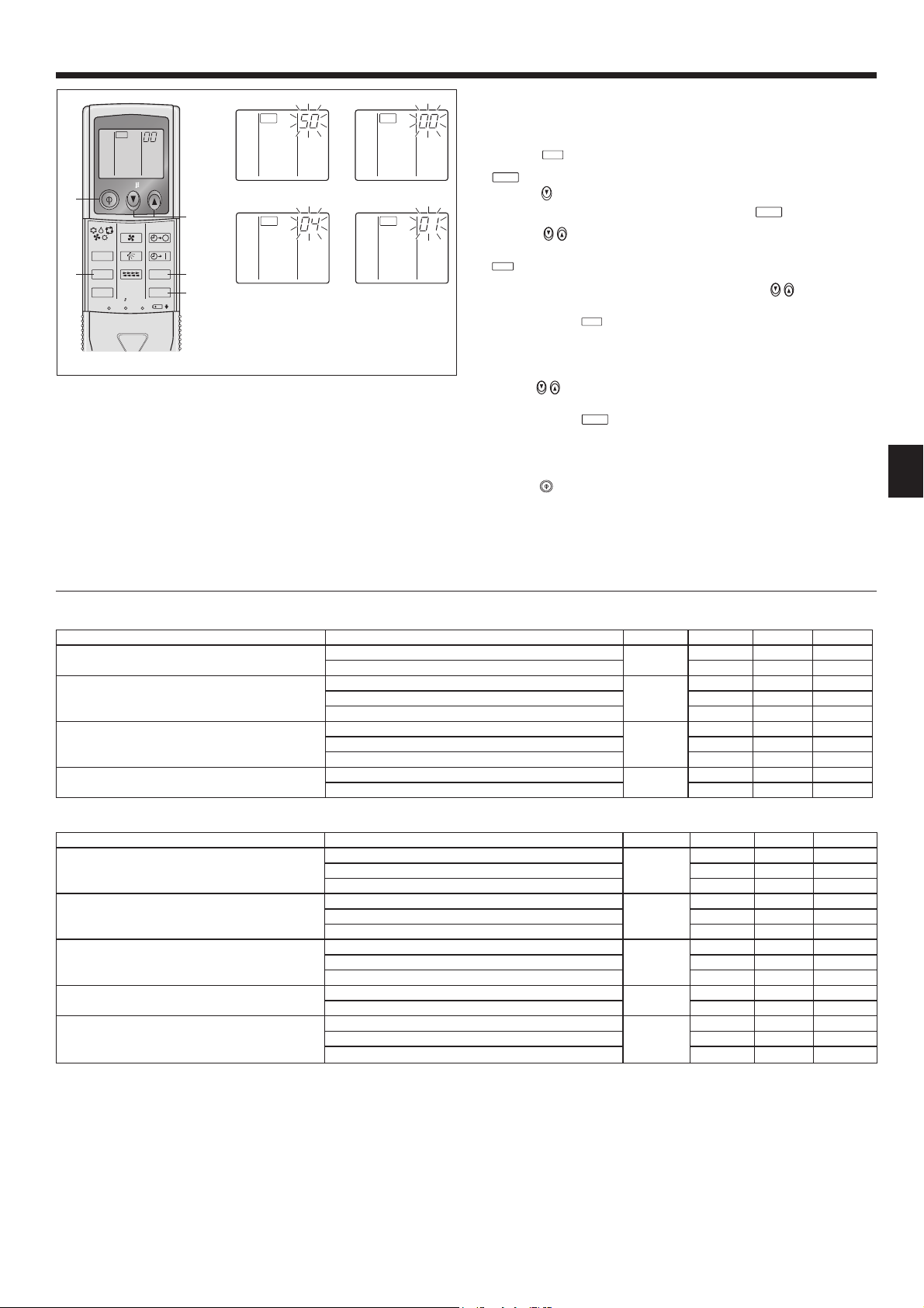
2) For wireless remote controller (Fig. 6-10)
Changing the power voltage setting
• Be sure to change the power voltage setting depending on the voltage used.
Going to the function select mode
1
Press the
(Start this operation from the status of remote controller display turned off.)
Press the
ler toward the receiver of the indoor unit and press the
Setting the unit number
2
Press the
button F twice continuously.
is lighted and “00” blinks.
temp button C once to set “50”. Direct the wireless remote control-
button A.
temp buttons C and D to set the unit number “00”. Direct the
wireless remote controller toward the receiver of the indoor unit and press the
button B.
Selecting a mode
3
Enter 04 to change the power voltage setting using the
temp buttons C
and D. Direct the wireless remote controller toward the receiver of the indoor
unit and press the
Current setting number: 1 = 1 beep (1 second)
button A.
2 = 2 beeps (1 second each)
3 = 3 beeps (1 second each)
Selecting the setting number
4
Use the
temp buttons C and D to change the power voltage setting to 01
(240 V). Direct the wireless remote controller toward the sensor of the indoor
unit and press the
To select multiple functions continuously
5
button A.
Repeat steps 3 and 4 to change multiple function settings continuously.
Complete function selection
6
Direct the wireless remote controller toward the sensor of the indoor unit and
press the
button E.
Note: Whenever changes are made to the function settings after installation
or maintenance, be sure to record the changes with a mark in the “Setting”
column of the Function table.
6.3.2. Function setting on the remote controller
Refer to the indoor unit operation manual.
Function table
Select unit number 00
Mode Settings Mode no. Setting no.
Power failure automatic recovery Not available
Available *1 2 Ο
01
Indoor temperature detecting Indoor unit operating average
Set by indoor unit’s remote controller 2
02
Remote controller’s internal sensor 3
LOSSNAY connectivity Not Supported
Supported (indoor unit is not equipped with outdoor-air intake)
03
Supported (indoor unit is equipped with outdoor-air intake) 3
Power voltage 240 V
220 V, 230 V 2 Ο
04
Select unit numbers 01 to 03 or all units (AL [wired remote controller]/07 [wireless remote controller])
Mode Settings Mode no. Setting no.
Filter sign 100Hr
2500Hr 2 Ο
07
No fi lter sign indicator 3
Fan speed Silent
Standard 2 Ο
08
High ceiling 3
No. of air outlets 4 directions
3 directions 2
09
2 directions 3
Installed options (high-performance fi lter) Not supported
Supported 2
10
Up/down vane setting Equipped with vanes (vanes angle setup 3)
Equipped with vanes (vanes angle setup 1)2
11
Equipped with vanes (vanes angle setup 2)
*1 When the power supply returns, the air conditioner will start 3 minutes later.
*2 Power failure automatic recovery initial setting depends on the connecting outdoor unit.
1
1 Ο
1 Ο
2
1
1
1
1 Ο
1 Ο
1
3 Ο
Initial setting
*2
Initial setting
setting
setting
11
6. Electrical work
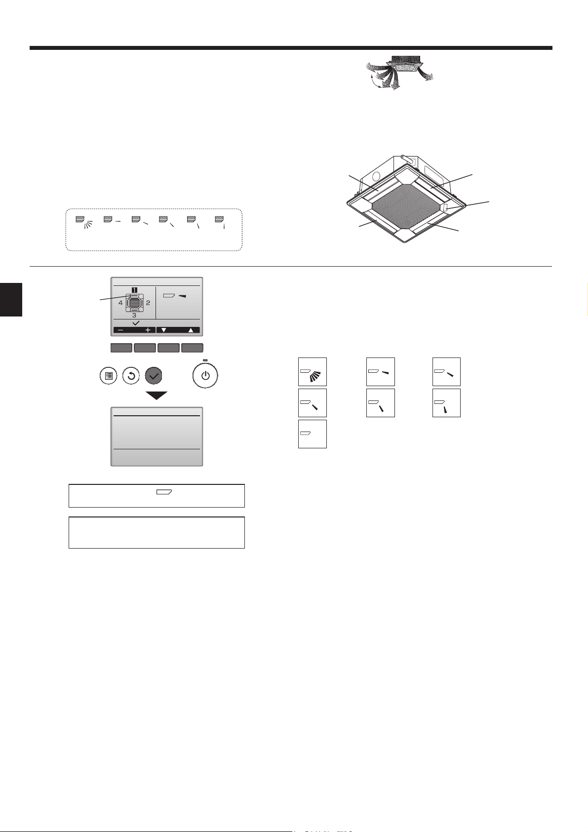
6.3.3 How to set the fi xed up/down air direction
(Only for wired remote controller and PUHZ, PU(H) application)
• Only the particular outlet can be fixed to certain direction with the
procedures below. Once fi xed, only the set outlet is fi xed every time air
conditioner is turned on. (Other outlets follow UP/DOWN air direction
setting of the remote controller.)
Explanation of word
■
• "Refrigerant address No." and "Unit No." are the numbers given to
each air conditioner.
• "Outlet No." is the number given to each outlet of air conditioner.
(Refer to the right.)
• "Up/Down air direction" is the direction (angle) to fi x.
Reset 1
MITSUBISHI
ELECTRIC LABEL
horizontal
2345
Manual vane angle
Select:
Outlet Angle
F1 F2 F3 F4
Horizontal airfl ow
Downward
Remote controller setting
The airfl ow direction of this outlet
is controlled by the airfl ow direc-
tion setting of remote controller.
Outlet No.3
Outlet No.2
Note: “0” indicates all outlets.
The current vane setting will appear.
Select the desired outlets from 1 through 4 with the [F1] or [F2] button.
• Outlet: "1", "2", "3", "4", and "1, 2, 3, 4, (all outlets)"
Press the [F3] or [F4] button to go through the option in the order of "No setting (reset)", "Step 1", "Step 2", "Step 3", "Step 4", and "Step 5".
Select the desired setting.
■ Vane setting
No setting
Fixed setting
The airfl ow direction of this outlet is fi xed
in particular direction.
* When it is cold because of direct
airfl ow, the airfl ow direction can be fi xed
horizontally to avoid direct airfl ow.
Outlet No.4
Outlet No.1
Step 1
Step 2
MITSUBISHI
ELECTRIC
label
Manual vane angle
Setting
If all outlets are selected, will be displayed the
next time the unit goes into operation.
Navigating through the screens
• To go back to the Main menu ..........[MENU] button
• To return to the previous screen .....[RETURN] button
Step 3
All outlets
Press the [SELECT] button to save the settings.
A screen will appear that indicates the setting information is being transmitted.
The setting changes will be made to the selected outlet.
The screen will automatically return to the one shown above (step 4) when the
transmission is completed.
Make the settings for other outlets, following the same procedures.
Step 4
Step 5
12
 Loading...