

Mitsubishi Electric PLA-RP3AA, PLA-RP4AA, PLA-RP5AA, PLA-RP6AA Service Manual
SPLIT-TYPE AIR CONDITIONERS
ON/OFF TEMP
MODEL SELECT
NOT AVAILABLE
CHECK
TEST RUN
˚C
AMPM
AMPM
ON/OFF
CENTRALLY CONTROLLED
ERROR CODE
CLOCK
ON OFF
˚C
CHECK
CHECK MODE
FILTER
TEST RUN
FUNCTION
˚C
1Hr.
NOT AVAILABLE
STAND BY
DEFROST
TEMP.
TECHNICAL & SERVICE MANUAL
No.OC297
Series PLA
Ceiling Cassettes
Indoor unit
[Model names] [Service Ref.]
PLA-RP3AA
PLA-RP4AA
PLA-RP5AA
PLA-RP6AA
INDOOR UNIT
PLA-RP3AA.UK
PLA-RP4AA.UK
PLA-RP5AA.UK
PLA-RP6AA.UK
R410A
• Refer to the OCT04 as for control
relation.This manual does not cover
outdoor units.
When serving them, please refer to
the service manual No.OC294 and
this manual in a set.
CONTENTS
1. SAFETY PRECAUTION·······························2
2. PART NAMES AND FUNCTIONS ···············4
3. SPECIFICATIONS········································7
4. DATA···························································11
5. OUTLINES AND DIMENSIONS·················23
6. WIRING DIAGRAM ····································24
7.
REFRIGERANT SYSTEM DIAGRAM
8. TROUBLESHOOTING ·······························26
9. DISASSEMBLY PROCEDURE··················37
10. PARTS LIST···············································40
11. OPTIONAL PARTS·····································46
···········25
WIRELESS REMOTE
CONTROLLER
WIRED REMOTE
CONTROLLER
Use new refrigerant pipes.
Make sure that the inside and outside of refrigerant piping is clean and it has no contamination
such as sulfur hazardous for use, oxides, dirt,
shaving particles, etc.
In addition, use pipes with specified thickness.
Store the piping to be used during installation
indoors and keep both ends of the piping sealed
until just before brazing. (Leave elbow joints, etc.
in their packaging.)
Use ester oil, ether oil or alkylbenzene oil (small
amount) as the refrigerant oil applied to flares
and flange connections.
In case of using the existing pipes for R22, be careful with
the followings.
· For RP4, 5 and 6, be sure to perform replacement opera tion before test run.
· Change flare nut to the one provided with this product.
Use a newly flared pipe.
· Avoid using thin pipes.
Charge refrigerant from liquid phase of gas
cylinder.
If the refrigerant is charged from gas phase, composition
change may occur in refrigerant and the efficiency will be
lowered.
Do not use refrigerant other than R410A.
If other refrigerant (R22 etc.) is used, chlorine in refrigerant can cause deterioration of refrigerant oil etc.
Use a vacuum pump with a reverse flow check
valve.
Vacuum pump oil may flow back into refrigerant cycle and
that can cause deterioration of refrigerant oil etc.
Use the following tools specifically designed for
use with R410A refrigerant.
The following tools are necessary to use R410A refrigerant.
Keep the tools with care.
If dirt, dust or moisture enter into refrigerant cycle, that can
cause deterioration of refrigerant oil or malfunction of compressor.
Do not use a charging cylinder.
If a charging cylinder is used, the composition of refrigerant will change and the efficiency will be lowered.
Flare tool
Electronic refrigerant
charging scale
Vacuum pump adaptor
Size adjustment gauge
Gauge manifold
Torque wrench
Gas leak detector
Charge hose
Tools (for R410A)
Contamination inside refrigerant piping can cause deterioration of refrigerant oil etc.
If dirt, dust or moisture enter into refrigerant cycle, that can
cause deterioration of refrigerant oil or malfunction of compressor.
If large amount of mineral oil enter, that can cause deterioration of refrigerant oil etc.
Ventilate the room if refrigerant leaks during
operation. If refrigerant comes into contact with
a flame, poisonous gases will be released.
1
SAFETY PRECAUTION
CAUTIONS RELATED TO NEW REFRIGERANT
<Cautions for units utilizing refrigerant R410A>
[1] Cautions for service
(1) Perform service after collecting the refrigerant left in unit completely.
(2) Do not release refrigerant in the air.
(3) After completing service, charge the cycle with specified amount of refrigerant.
(4) When performing service, install a filter drier simultaneously.
Be sure to use a filter drier for new refrigerant.
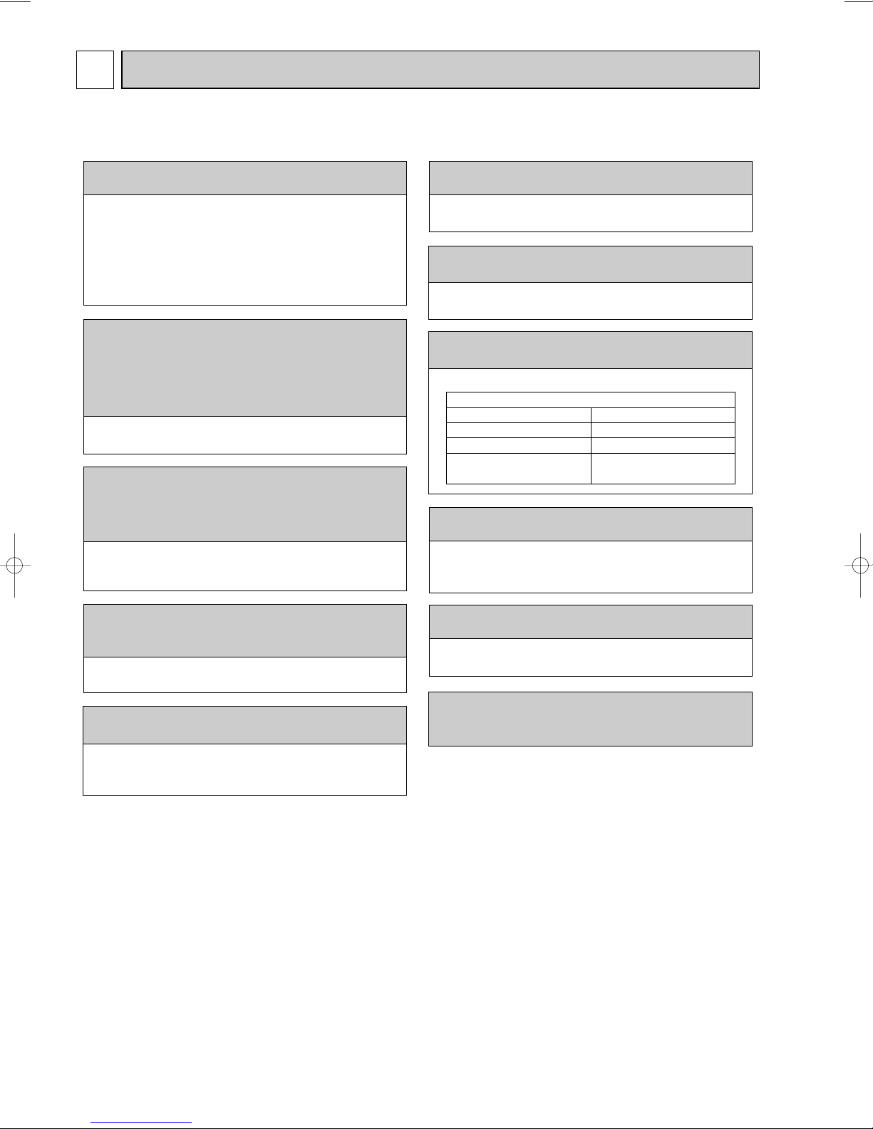
[2] Additional refrigerant charge
When charging directly from cylinder
· Check that cylinder for R410A on the market is syphon type.
· Charging should be performed with the cylinder of syphon stood vertically. (Refrigerant is charged from liquid phase.)
2
Gravimeter
Unit
[3] Service tools
Use the below service tools as exclusive tools for R410A refrigerant.
No. Specifications
1 Gauge manifold ·Only for R410A
·Use the existing fitting
·Use high-tension side pressure of 5.3MPa·G or over.
2 Charge hose ·Only for R410A
·Use pressure performance of 5.09MPa·G or over.
3 Electronic scale
4 Gas leak detector ·Use the detector for R134a, R407C or R410A.
5 Adaptor for reverse flow check ·Attach on vacuum pump.
6 Refrigerant charge base
7 Refrigerant cylinder ·Only for R410A Top of cylinder (Pink)
8 Refrigerant recovery equipment
specifications
Cylinder with syphon
. (UNF1/2)
3
PAR-20MAA
ON/OFF
CENTRALLY CONTROLLED
ERROR CODE
CLOCK
ON OFF
˚C
CHECK
CHECK MODE
FILTER
TEST RUN
FUNCTION
˚C
1Hr.
NOT AVAILABLE
STAND BY
DEFROST
FILTER
CHECK TEST
TEMP.
TIMER SET
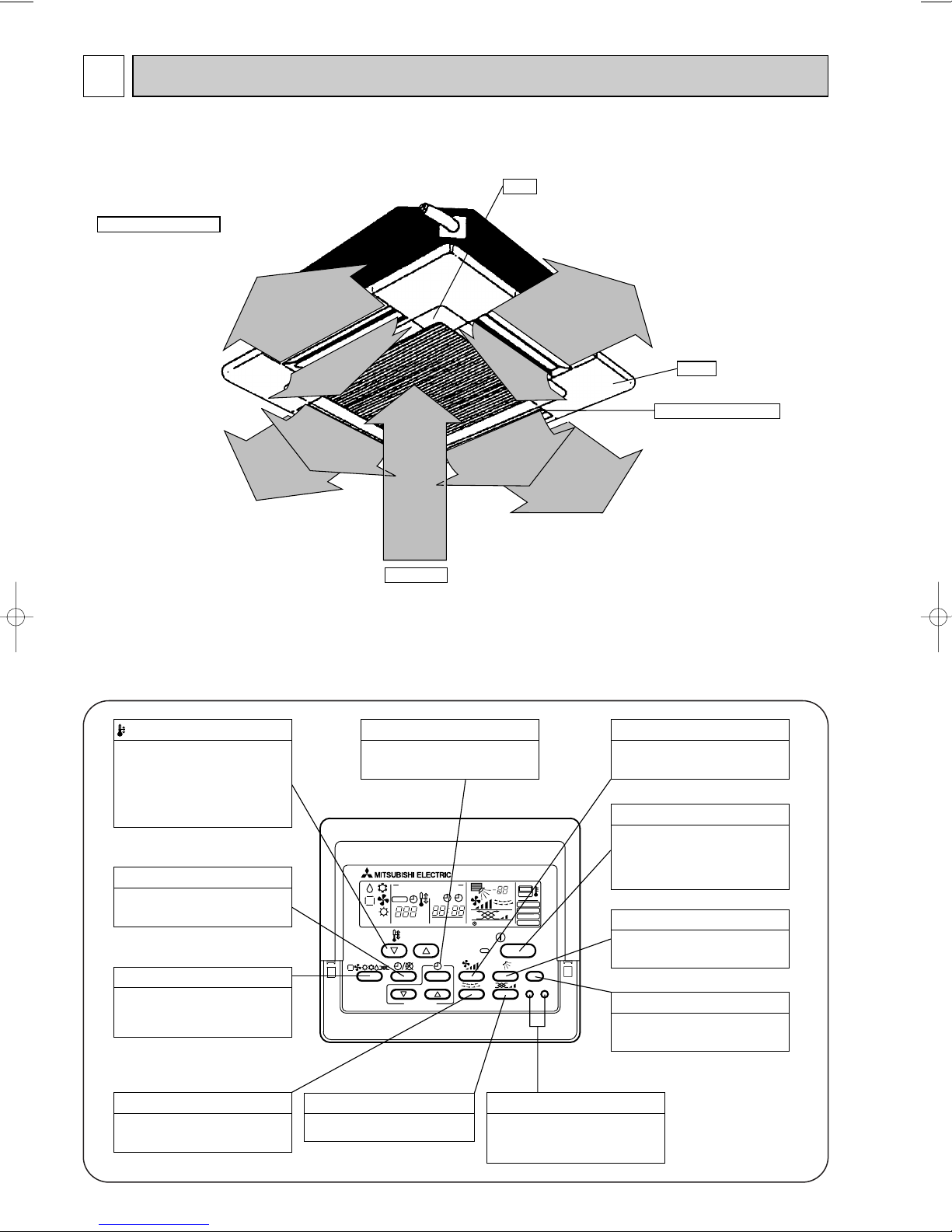
This sets the ventilation fan speed.
VENTILATION button
Press this button to switch the cooling,
electronic dry (dehumidify), automatic
and heating modes.
OPERATION SWITCH button
This sets the room temperature. The
temperature setting can be performed
in 1: units
Setting range
Cooling 19: to 30:
Heating 17: to 28:
TEMP. ADJUSTMENT button
This switches between continuous
operation and the timer operation.
TIMER button
This switches between the operation
and stop modes each time it is pressed.
The lamp on this button lights during
operation.
ON/OFF button
Only press this button to perform an
inspection check or test operation.
Do not use it for normal operation.
CHECK-TEST RUN button
This switch the horizontal fan motion
ON and OFF.
(Not available for this model.)
LOUVER button
This adjusts the vertical angle of the
ventilation.
AIR DIRECTION button
This resets the filter service indication
display
FILTER button
This sets the current time, start time
and stop time.
TIME SETTING button
This sets the ventilation fan speed.
FAN SPEED button
2
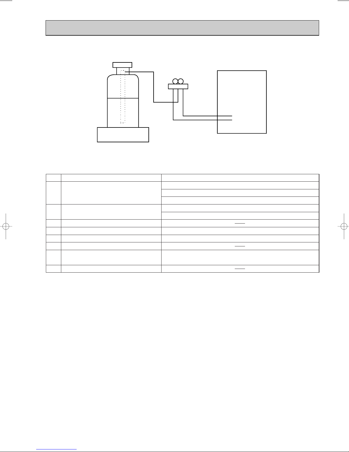
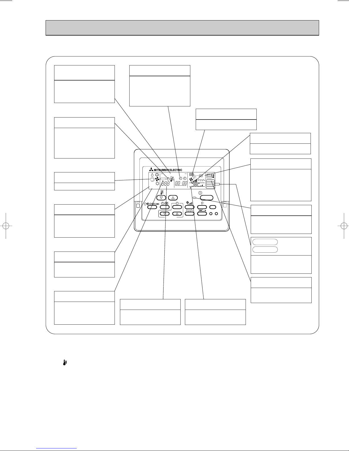
Auto Air Swing Vane
Disperses airflow up and
down and adjusts the angle
of airflow direction.
Grille
Filter
Removes dust and pollutants
from intake air
Horizontal Air Outlet
Sets airflow of horizontal automatically
during cooling or dehumidifying.
Air Intake
Intakes air from room.
PART NAMES AND FUNCTIONS
● Indoor (Main) Unit
PLA-RP3AA.UK, PLA-RP4AA.UK, PLA-RP5AA.UK, PLA-RP6AA.UK
● Wired remote controller
On the controls are set, the same operation mode can be repeated by simply pressing the ON/OFF button.
PLA-RP3AA.UK, PLA-RP4AA.UK, PLA-RP5AA.UK, PLA-RP6AA.UK
● Operation buttons
4
● Display
PAR-20MAA
ON/OFF
CENTRALLY CONTROLLED
ERROR CODE
CLOCK
ON OFF
˚C
CHECK
CHECK MODE
FILTER
TEST RUN
FUNCTION
˚C
1Hr.
NOT AVAILABLE
STAND BY
DEFROST
FILTER
CHECK TEST
TEMP.
TIMER SET
CENTRALLY
CONTROLLED display
This indicates when the unit is con-
trolled by optional features such as
central control type remote controller.
TIMER display
This indicates when the continuous
operation and time operation modes
are set.
It also display the time for the timer
operation at the same time as when
it is set.
OPERATION MODE display
This indicates the operation mode.
STANDBY display
The [STANDBY] symbol is only dis-
played from the time the heating
operation starts unit the heated air
begins to blow.
DEFROST display
This indicates when the defrost oper-
ation is performed.
CLOCK display
The current time , start time and stop
time can be displayed in ten second
intervals by pressing the time switch
button. The start time or stop time is
always displayed during the timer
operation.
In this display example on the bottom left, a condition where all display lamps light is shown for explanation purposes although this differs
from actual operation.
AIR DIRECTION display
This displays the air direction.
AIR SPEED display
The selected fan speed is displayed.
ROOM TEMPERATURE display
The temperature of the suction air
is displayed during operation. The
display range is 8°C to 39°C. The
display flashes 8°C when the actual
temperature is less than 8°C and
flashes 39°C when the actual temperature is greater than 39°C.
Operation lamp
This lamp lights during operation,
goes off when the unit stops and
flashes when a malfunction occurs.
CHECK MODE
TEST RUN
This display lights in the check mode
or when a test operation is performed.
display
CHECK display
This indicates when a malfunction
has occurred in the unit which should
be checked.
Caution
● Only the Power display lights when the unit is stopped and power supplied to the unit.
● When the central control remote control unit, which is sold separately, is used the ON-OFF button, operation switch button
and TEMP. adjustment button do not operate.
● “NOT AVAILABLE” is displayed when the Air speed button are pressed.This indicates that this room unit is not equipped
with the fan direction adjustment function and the louver function.
● When power is turned ON for the first time, it is normal that “H0” is displayed on the room temperature indication (For max.
2minutes). Please wait until this “H0” indication disappear then start the operation.
SET TEMPERATURE display
This displays the selected setting
temperature.
POWER display
This lamp lights when electricity is
supplied to the unit.
5
FILTER display
This lamp lights when the filter need
to be cleaned.
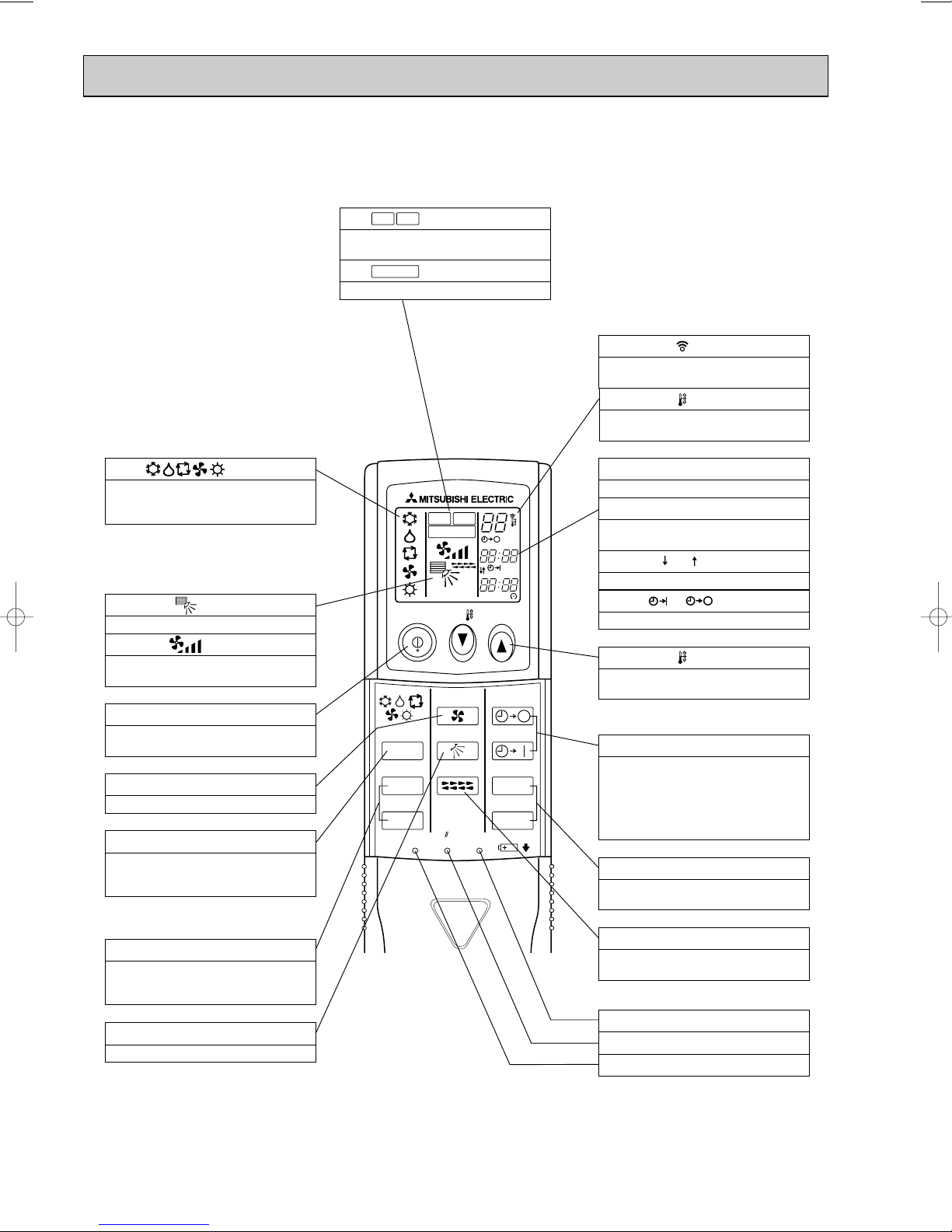
● Wireless remote controller
ON/OFF TEMP
FAN
VANE
TEST RUN
AUTO STOP
AUTO START
h
min
LOUVER
MODE
CHECK
RESETSET CLOCK
MODEL SELECT
NOT AVAILABLE
CHECK
TEST RUN
˚C
AMPM
AMPM
VANE CONTROL button
Used to change the air flow direction.
CLOCK button
RESET button
SET button
ON/OFF button
The unit is turned ON and OFF alternately
each time the button is pressed.
LOUVER button
This switch the horizontal fan motion ON
and OFF.
(Not available for this model.)
MODE SELECT button
Used to switch the operation mode between
cooling, drying, blowing, heating and auto
mode.
CHECK-TEST RUN button
Only press this button to perform an inspection check or test operation.
Do not use it for normal operation.
FAN SPEED SELECT button
Used to change the fan speed.
TIMER display
Displays when in timer operation or when
setting timer.
button
SET TEMPERATURE button sets any desired
room temperature.
CLOCK display
Displays the current time.
“ ” “ ” display
Displays the order of timer operation.
“ ” “ ” display
Displays whether timer is on or off.
w In case the outdoor unit is cool only type,
the heating mode is not available.
Buttons used to set the “hour and minute” of
the current time and timer settings.
h and min buttons
display
SET TEMP. display indicates desired temperature set.
display
FAN SPEED display indicates which fan
speed has been selected.
display
The vertical direction of air flow is indicated.
display
Blinks when model is selected.
display
Lights up while transmission to the indoor
unit is mode using switches.
display
CHECK&TEST RUN display indicates that
the unit is being checked or test-run.
display
OPERATION MODE display
Operation mode display indicates which operation mode is in effect.
TIMER CONTROL buttons
AUTO STOP (OFF timer): when this switch
is set, the air conditioner will be automatically stopped at the preset time.
AUTO START (ON timer): when this switch
is set, the air conditioner will be automatically started at the preset time.
MODEL SELECT
CHECK
TEST RUN
PLA-RP3AA.UK, PLA-RP4AA.UK, PLA-RP5AA.UK, PLA-RP6AA.UK
6
3
Service Ref.
Item
Function
Capacity
Btu/h
W
Total input
Service Ref.
Power supply (phase, cycle,voltage)
Input
Running current A
Starting current A
External finish (Panel)
Heat exchanger
Fan
Fan (drive) o No.
Fan motor output kW
kW
kW
Airflow (Lo-Mi2-Mi1-Hi)
K / min (CFM)
External static pressure Pa (mmAq)
Booster heater kW
Operation control & Thermostat
Sound level (Lo-Mi2-Mi1-Hi) dB
Unit drain pipe I.D. mm (in.)
Dimensions
Indoor unit
W mm (in.)
D mm (in.)
H mm (in.)
Weight
kg (lbs.)
Service Ref.
Power supply (phase, cycle, voltage)
Running current A
External finish
Refrigerant control
Compressor
Model
Motor output kW
Starter type
Protection devices
Heat exchanger
Fan (drive) o No.
Fan Fan motor output kW
Airflow K
/ min (CFM)
Crankcase heater W
Defrost method
Sound level
Dimensions
Cooling dB
Heating dB
W mm (in.)
D mm (in.)
H mm (in.)
Outdoor unitRefrigerant piping
Weight kg (lbs.)
Refrigerant
Charge kg (lbs.)
Oil (Model) L
Pipe size O.D.
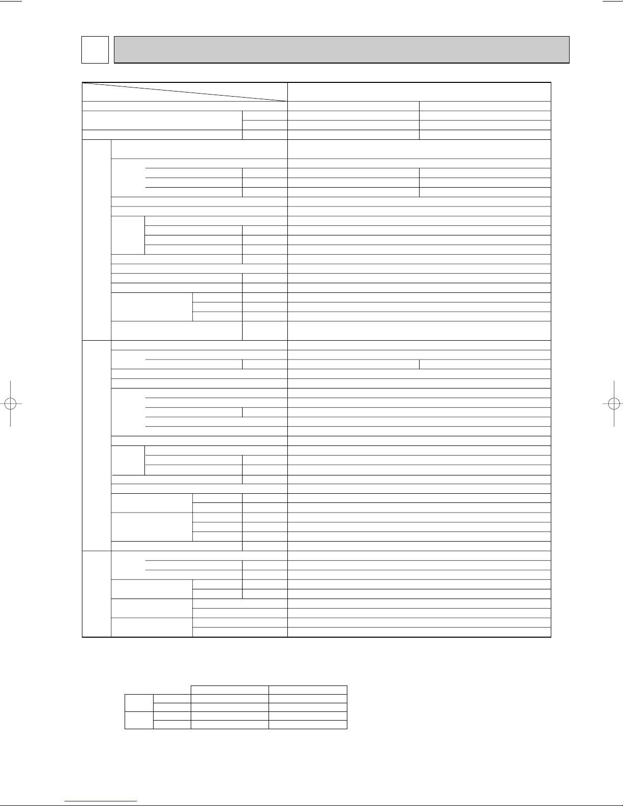
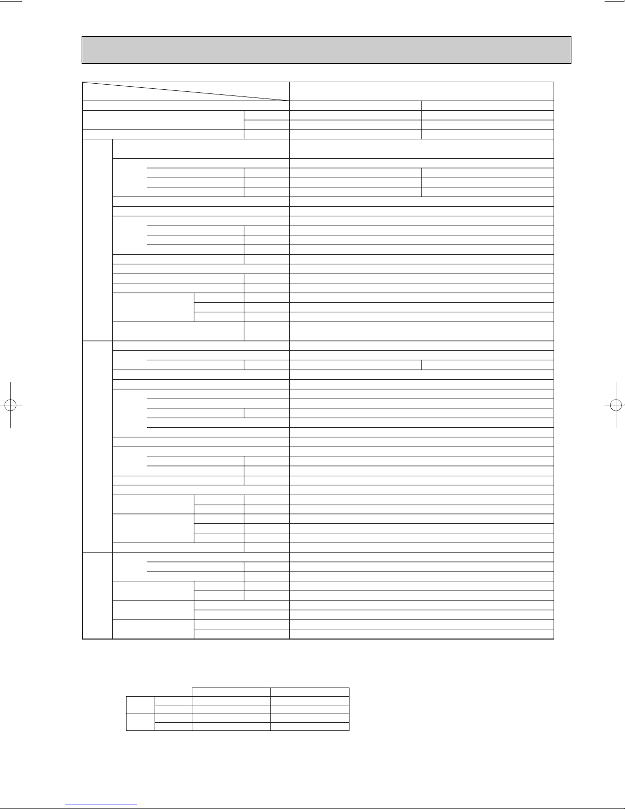
PLA-RP3AA.UK
Cooling Heating
24,200 27,300
7,100 (3,300~8,100) 8,000 (3,500~10,200)
1.97 2.34
PLA-RP3AA.UK
Single phase, 50Hz, 220-230-240V
0.16 0.16
0.79 0.79
1.0 1.0
Munsell 0.70Y 8.59/0.97
Plate fin coil
T
urbo fan (direct) o1
0.070
15-16-18-20 (530-565-635-705)
0 (direct blow)
—
Remote controller & built-in
28-30-32-34
32 (1-1/4)
UNIT : 840 (33-1/16) PANEL : 950 (37-3/8)
UNIT : 840 (33-1/16) PANEL : 950 (37-3/8)
UNIT : 258 (10-1/2) PANEL : 30 (1-3/16)
UNIT : 24 (53)
PUHZ-RP3VHA
Single phase, 50Hz, 220-230-240V
8.04
9.74
Munsell 3Y 7.8/1.1
Linear expansion valve
Hermetic
TNB220FMBH
1.6
Line start
HP switch, Discharge thermo.
Plate fin coil
Propeller (direct) o1
0.060
55 (1,940)
—
Reverse cycle
47
48
950 (37-3/8)
330+30 (13+1-3/16)
943 (37-1/8)
75 (165)
R410A
3.5 (7.7)
0.87 (NEO22)
9.52 (3/8)
15.88 (5/8)
Flared
Flared
Max. 30m
Max. 50m
Liquid mm (in.)
Gas mm (in.)
Connection method
Indoor side
Outdoor side
NOTE: 1. Rating conditions (ISO T1)
Cooling Indoor : D.B. 27: (80˚F) W.B. 19: (66˚F) Outdoor: D.B. 35: (95˚F) W.B. 24: (75˚F)
Heating Indoor: D.B. 20: (68˚F) Outdoor : D.B. 7: (45˚F) W.B. 6: (43˚F)
Refrigerant piping length (one way) : 5m (16ft.)
2. Guaranteed operating range
Indoor Outdoor
Cooling
Upper limit
D.B. 35˚C, W.B. 22.5˚C
D.B. 46˚C
Lower limit
D.B. 19˚C, W.B. 15˚C D.B. -5˚C
Heating
Upper limit
D.B. 28˚C
D.B. 21˚C, W.B. 15˚C
Lower limit
D.B. 17˚C
D.B. -11˚C, W.B. -12˚C
Between the indoor &
outdoor units
Height difference
Piping length
3. Above data based on indicated voltage
Indoor unit Single phase 230V 50Hz
Single phase 230V 50Hz
Outdoor unit
PANEL: 5 (11)
SPECIFICATIONS
7
Indoor Outdoor
Cooling
Upper limit
D.B. 35˚C, W.B. 22.5˚C
D.B. 46˚C
Lower limit
D.B. 19˚C, W.B. 15˚C
D.B. -5˚C
Heating
Upper limit
D.B. 28˚C
D.B. 21˚C, W.B. 15˚C
Lower limit
D.B. 17˚C
D.B. -11˚C, W.B. -12˚C
Service Ref.
Item
Function
Capacity
Btu/h
W
Total input
Service Ref.
Power supply (phase, cycle,voltage)
Input
Running current A
Starting current A
External finish (Panel)
Heat exchanger
Fan
Fan (drive) o No.
Fan motor output kW
kW
kW
Airflow (Lo-Mi2-Mi1-Hi)
K / min (CFM)
External static pressure Pa (mmAq)
Booster heater kW
Operation control & Thermostat
Sound level (Lo-Mi2-Mi1-Hi) dB
Unit drain pipe I.D. mm (in.)
Dimensions
Indoor unit
W mm (in.)
D mm (in.)
H mm (in.)
Weight
kg (lbs.)
Service Ref.
Power supply (phase, cycle, voltage)
Running current A
External finish
Refrigerant control
Compressor
Model
Motor output kW
Starter type
Protection devices
Heat exchanger
Fan (drive) o No.
Fan Fan motor output kW
Airflow
K / min (CFM)
Crankcase heater W
Defrost method
Sound level
Dimensions
Cooling dB
Heating dB
W mm (in.)
D mm (in.)
H mm (in.)
Outdoor unitRefrigerant piping
Weight kg (lbs.)
Refrigerant
Charge kg (lbs.)
Oil (Model) L
Pipe size O.D.
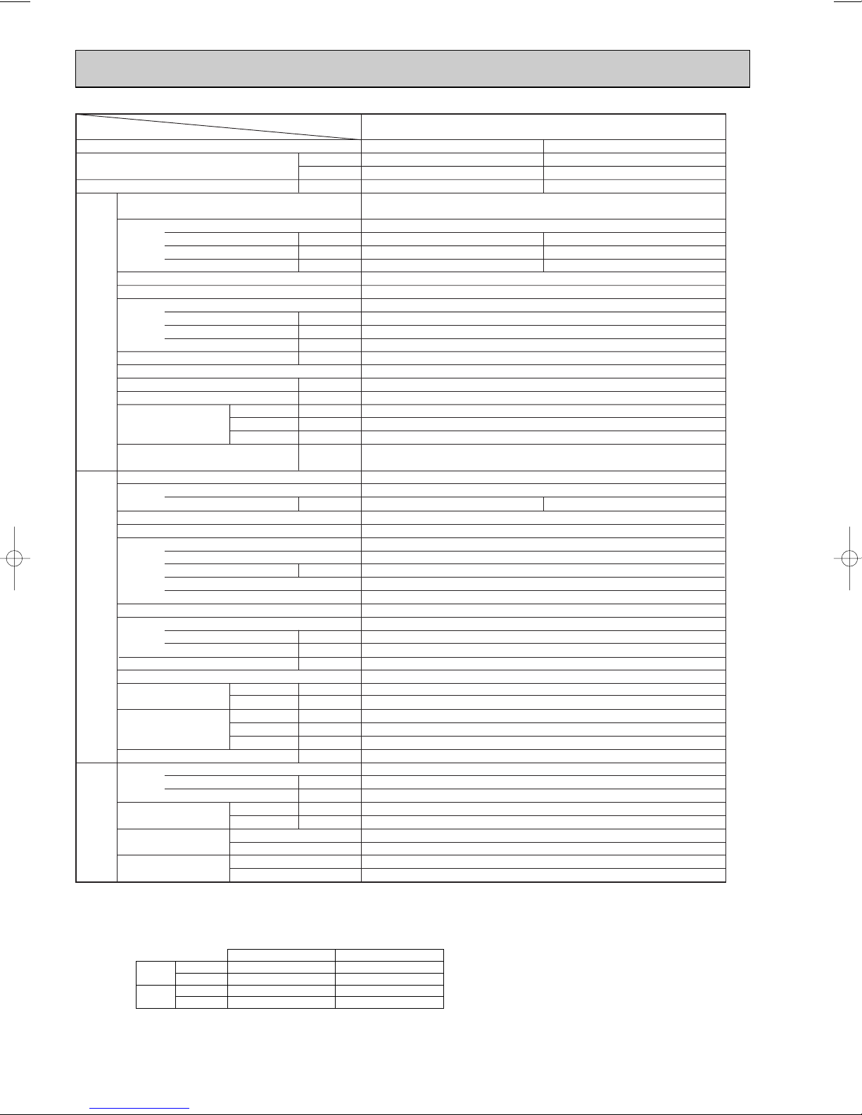
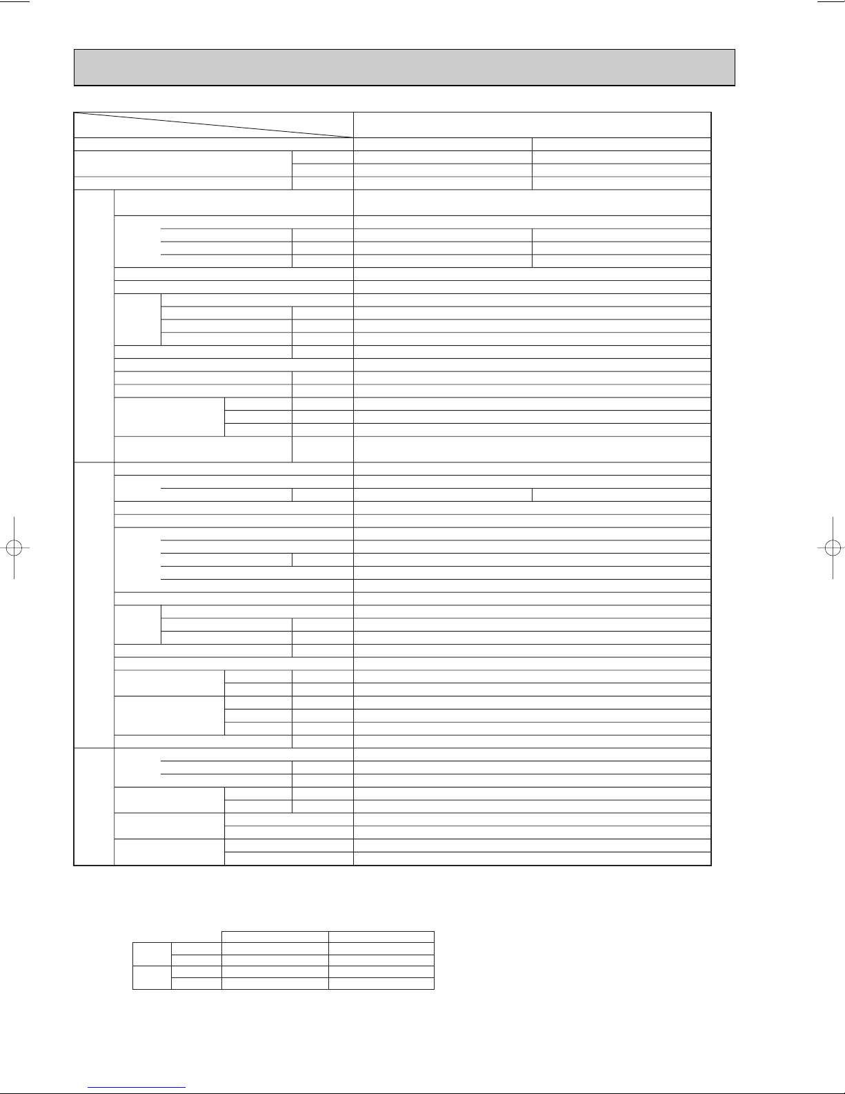
PLA-RP4AA.UK
Cooling Heating
34,100 38,200
10,000 (5,000~11,400) 11,200 (5,600~14,000)
3.03 3.39
PLA-RP4AA.UK
Single phase, 50Hz, 220-230-240V
0.25 0.25
1.25 1.25
2.0 2.0
Munsell 0.70Y 8.59/0.97
Plate fin coil
Turbo fan (direct) o1
0.120
20-23-26-28 (705-810-920-990)
0 (direct blow)
—
Remote controller & built-in
33-36-39-41
32 (1-1/4)
UNIT : 840 (33-1/16) PANEL : 950 (37-3/8)
UNIT : 840 (33-1/16) PANEL : 950 (37-3/8)
UNIT : 298 (11-3/4) PANEL : 30 (1-3/16)
UNIT : 30 (66) PANEL : 5 (11)
PUHZ-RP4VHA
Single phase, 50Hz, 220-230-240V
12.33 13.94
Munsell 3Y 7.8/1.1
Linear expansion valve
Hermetic
ANV33FDAMT
1.9
Line start
HP switch, LP switch, Discharge thermo.
Plate fin coil
Propeller (direct) o2
0.060+0.060
100 (3,530)
—
Reverse cycle
49
51
950 (37-3/8)
330+30 (13+1-3/16)
1,350 (53-1/8)
121 (267)
R410A
5.5 (12.1)
1.4 (MEL56)
9.52 (3/8)
15.88 (5/8)
Flared
Flared
Max. 30m
Max. 75m
Liquid mm (in.)
Gas mm (in.)
Connection method
Indoor side
Outdoor side
Between the indoor &
outdoor units
Height difference
Piping length
NOTE: 1. Rating conditions (ISO T1)
Cooling Indoor : D.B. 27: (80˚F) W.B. 19: (66˚F) Outdoor: D.B. 35: (95˚F) W.B. 24: (75˚F)
Heating Indoor: D.B. 20: (68˚F) Outdoor : D.B. 7: (45˚F) W.B. 6: (43˚F)
Refrigerant piping length (one way) : 5m (16ft.)
2. Guaranteed operating range
3. Above data based on indicated voltage
Indoor unit Single phase 230V 50Hz
Outdoor unit Single phase 230V 50Hz
8
Item
Function
Capacity
Total input
Service Ref.
Power supply (phase, cycle,voltage)
Input
Running current A
Starting current A
External finish (Panel)
Heat exchanger
Fan (drive) o No.
Fan
Indoor unit
Booster heater kW
Fan motor output kW
Airflow (Lo-Mi2-Mi1-Hi)
External static pressure Pa (mmAq)
Operation control & Thermostat
Sound level (Lo-Mi2-Mi1-Hi) dB
Unit drain pipe I.D. mm (in.)
Dimensions
Weight
Service Ref.
Power supply (phase, cycle, voltage)
Running current
External finish
Refrigerant control
Compressor
Model
Motor output kW
Starter type
Protection devices
Heat exchanger
Fan (drive) o No.
Fan Fan motor output kW
Outdoor unitRefrigerant piping
Airflow
Crankcase heater W
Defrost method
Sound level
Dimensions
Weight kg (lbs.)
Refrigerant
Charge kg (lbs.)
Oil (Model) L
Pipe size O.D.
Connection method
Between the indoor &
outdoor units
NOTE: 1. Rating conditions (ISO T1)
Cooling : Indoor: D.B. 27: (80˚F) W.B. 19: (66˚F) Outdoor: D.B. 35: (95˚F) W.B. 24: (75˚F)
Heating : Indoor: D.B. 20: (68˚F) Outdoor: D.B. 7: (45˚F) W.B. 6: (43˚F)
Refrigerant piping length (one way) : 5m (16ft.)
2. Guaranteed operating range
Upper limit D.B. 35:, W.B. 22.5: D.B. 46:
Cooling
Lower limit D.B. 19 :, W.B. 15: D.B. -5:
Upper limit D.B. 28
Heating
Lower limit D.B. 17: D.B. -11:, W.B. -12:
Service Ref.
Btu/h
W
kW
kW
K / min (CFM)
W mm (in.)
D mm (in.)
H mm (in.)
kg (lbs.)
A
K / min (CFM)
Cooling dB
Heating dB
W mm (in.)
D mm (in.)
H mm (in.)
Liquid mm (in.)
Gas mm (in.)
Indoor side
Outdoor side
Height difference
Piping length
Indoor Outdoor
:
12,500 (6,000~14,000)
D.B. 21:, W.B. 15:
PLA-RP5AA.UK
Cooling
42,700
Heating
47,800
14,000 (6,000~16,000)
3.89
4.27
PLA-RP5AA.UK
Single phase, 50Hz, 220-230-240V
0.33 0.33
1.64
1.64
2.0
Munsell 0.70Y 8.59/0.97
Plate fin coil
urbo fan (direct) o1
T
0.120
22-25-28-30 (775-880-990-1,060)
0 (direct blow)
—
Remote controller & built-in
37-40-43-45
32 (1-1/4)
UNIT : 840 (33-1/16) PANEL : 950 (37-3/8)
UNIT : 840 (33-1/16) PANEL : 950 (37-3/8)
: 298 (11-3/4)
UNIT
PANEL
: 30 (1-3/16)
UNIT : 32 (71) PANEL : 5 (11)
PUHZ-RP5VHA
Single phase, 50Hz, 220-230-240V
15.80 17.50
Munsell 3Y 7.8/1.1
Linear expansion valve
Hermetic
ANV33FDAMT
2.4
Line start
HP switch, LP switch, Discharge thermo.
Plate fin coil
Propeller (direct) o2
0.060+0.060
100 (3,530)
—
Reverse cycle
50
52
950 (37-3/8)
330+30 (13+1-3/16)
1,350 (53-1/8)
121 (267)
R410A
5.5 (12.1)
1.4 (MEL56)
9.52 (3/8)
15.88 (5/8)
Flared
Flared
Max. 30m
Max. 75m
3. Above data based on indicated voltage
Indoor unit Single phase 230V 50Hz
Outdoor unit Single phase 230V 50Hz
2.0
9
Service Ref.
Item
Function
Capacity
Btu/h
W
kW
Total input
Service Ref.
Power supply (phase, cycle,voltage)
Input
Running current A
Starting current A
External finish (Panel)
Heat exchanger
Fan
Fan (drive) o No.
Fan motor output kW
kW
Airflow (Lo-Mi2-Mi1-Hi)
K / min (CFM)
External static pressure Pa (mmAq)
Booster heater kW
Operation control & Thermostat
Sound level (Lo-Mi2-Mi1-Hi) dB
Unit drain pipe I.D. mm (in.)
Dimensions
Indoor unit
W mm (in.)
D mm (in.)
H mm (in.)
Weight
kg (lbs.)
Service Ref.
Power supply (phase, cycle, voltage)
Running current
A
External finish
Refrigerant control
Compressor
Model
Motor output kW
Starter type
Protection devices
Heat exchanger
Fan (drive) o No.
Fan Fan motor output kW
Airflow
K / min (CFM)
Crankcase heater W
Defrost method
Sound level
Dimensions
Cooling dB
Heating dB
W mm (in.)
D mm (in.)
H mm (in.)
Outdoor unitRefrigerant piping
Weight kg (lbs.)
Refrigerant
Charge kg (lbs.)
Oil (Model) L
Pipe size O.D.
PLA-RP6AA.UK
Cooling
Heating
47,800 54,600
14,000 (6,200~15,300)
16,000 (6,200~18,000)
4.99 4.91
PLA-RP6AA.UK
Single phase, 50Hz, 220-230-240V
0.33 0.33
1.64 1.64
2.0 2.0
Munsell 0.70Y 8.59/0.97
Plate fin coil
T
urbo fan (direct) o1
0.120
22-25-28-30 (775-880-990-1,060)
0 (direct blow)
Remote controller & built-in
37-40-43-45
32 (1-1/4)
UNIT : 840 (33-1/16) PANEL : 950 (37-3/8)
UNIT : 840 (33-1/16) PANEL : 950 (37-3/8)
UNIT : 298 (11-3/4) PANEL : 30 (1-3/16)
UNIT : 32 (71) PANEL : 5 (11)
PUHZ-RP6VHA
Single phase, 50Hz, 220-230-240V
20.73 20.37
Munsell 3Y 7.8/1.1
Linear expansion valve
Hermetic
ANV33FDAMT
2.9
Line start
HP switch, LP switch, Discharge thermo.
Plate fin coil
Propeller (direct) o2
0.060+0.060
100 (3,530)
—
Reverse cycle
50
52
950 (37-3/8)
330+30 (13+1-3/16)
1,350 (53-1/8)
121 (267)
R410A
5.5 (12.1)
1.4 (MEL56)
9.52 (3/8)
15.88 (5/8)
Flared
Flared
Max. 30m
Max. 75m
Liquid mm (in.)
Gas mm (in.)
Connection method
Indoor side
Outdoor side
Between the indoor &
outdoor units
Height difference
Piping length
NOTE: 1. Rating conditions (ISO T1)
Cooling : Indoor: D.B. 27: (80˚F) W.B. 19: (66˚F) Outdoor: D.B. 35: (95˚F) W.B. 24: (75˚F)
Heating : Indoor: D.B. 20: (68˚F) Outdoor: D.B. 7: (45˚F) W.B. 6: (43˚F)
Refrigerant piping length (one way) : 5m (16ft.)
2. Guaranteed operating range
Indoor Outdoor
Cooling
Upper limit D.B. 35:, W.B. 22.5: D.B. 46:
Lower limit D.B. 19 :, W.B. 15:
D.B. -5 :
Heating
Upper limit D.B. 28
:
D.B. 21 :, W.B. 15:
Lower limit D.B. 17: D.B. -11:, W.B. -12:
3. Above data based on indicated voltage
Indoor unit Single phase 230V 50Hz
Outdoor unit Single phase 230V 50Hz
—
10
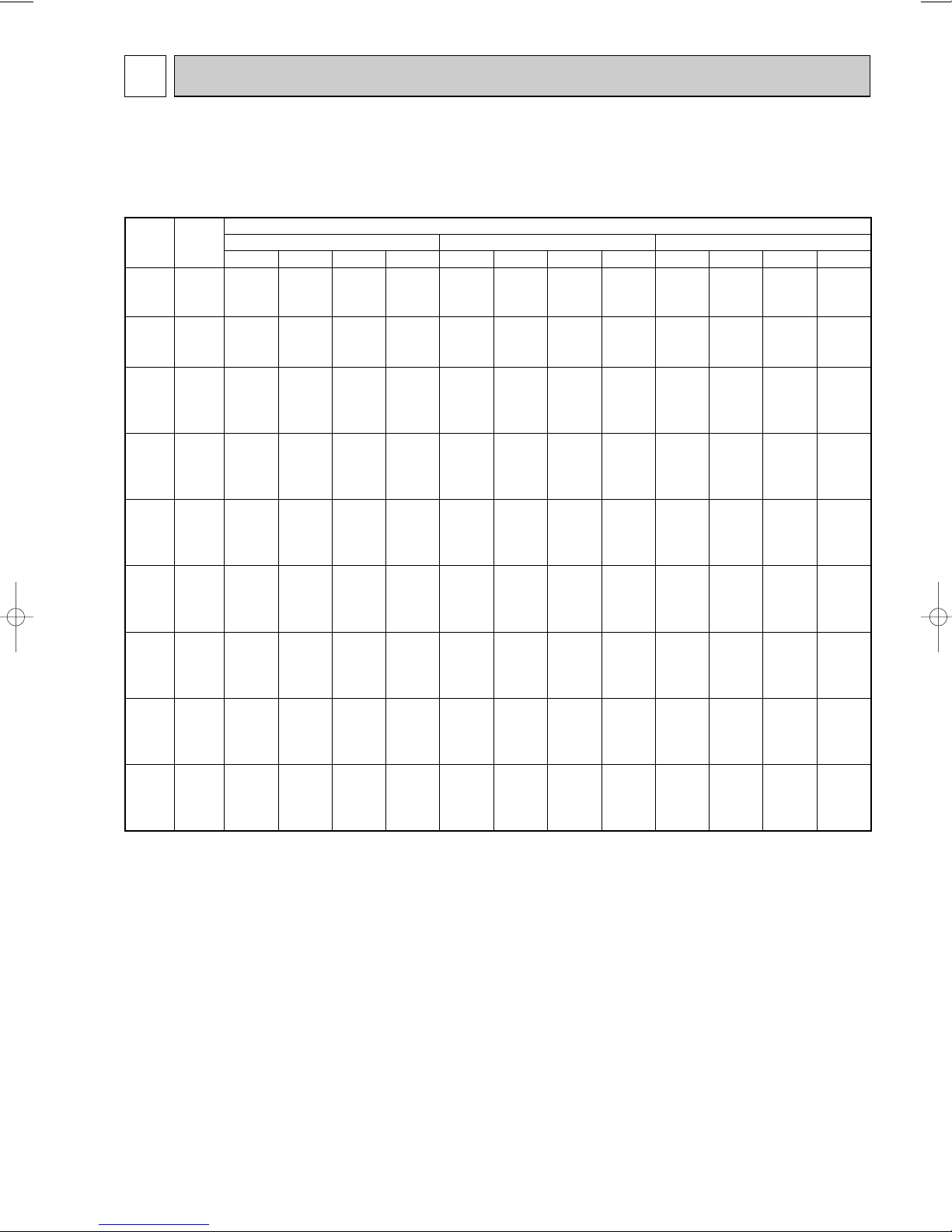
DATA4
4-1-1. COOLING CAPACITY (1)
PLA-RP3AA.UK / PUHZ-RP3VHA
(230V)
NOTE:
CA: Capacity (W) SHC: Sensible heat capacity (W)
P.C.: Power consumption (kW) SHF: Sensible heat factor
20
20
20
22
22
22
24
24
24
24
26
26
26
26
27
27
27
27
28
28
28
28
30
30
30
30
32
32
32
32
34
34
34
34
16
18
20
16
18
20
16
18
20
22
16
18
20
22
16
18
20
22
16
18
20
22
16
18
20
22
16
18
20
22
16
18
20
22
7,029
7,526
8,094
7,029
7,526
8,094
7,029
7,526
8,094
8,627
7,029
7,526
8,094
8,627
7,029
7,526
8,094
8,627
7,029
7,526
8,094
8,627
7,029
7,526
8,094
8,627
7,029
7,526
8,094
8,627
7,029
7,526
8,094
8,627
4,499
3,914
3,238
5,061
4,516
3,885
5,623
5,118
4,533
3,796
6,186
5,720
5,180
4,486
6,467
6,021
5,504
4,831
6,748
6,322
5,828
5,176
7,029
6,924
6,475
5,866
7,029
7,526
7,123
6,556
7,029
7,526
7,770
7,246
0.64
0.52
0.40
0.72
0.60
0.48
0.80
0.68
0.56
0.44
0.88
0.76
0.64
0.52
0.92
0.80
0.68
0.56
0.96
0.84
0.72
0.60
1.00
0.92
0.80
0.68
1.00
1.00
0.88
0.76
1.00
1.00
0.96
0.84
1.58
1.61
1.65
1.58
1.61
1.65
1.58
1.61
1.65
1.69
1.58
1.61
1.65
1.69
1.58
1.61
1.65
1.69
1.58
1.61
1.65
1.69
1.58
1.61
1.65
1.69
1.58
1.61
1.65
1.69
1.58
1.61
1.65
1.69
6,816
7,313
7,917
6,816
7,313
7,917
6,816
7,313
7,917
8,449
6,816
7,313
7,917
8,449
6,816
7,313
7,917
8,449
6,816
7,313
7,917
8,449
6,816
7,313
7,917
8,449
6,816
7,313
7,917
8,449
6,816
7,313
7,917
8,449
4,362
3,803
3,167
4,908
4,388
3,800
5,453
4,973
4,433
3,718
5,998
5,558
5,067
4,393
6,271
5,850
5,383
4,731
6,543
6,143
5,700
5,069
6,816
6,728
6,333
5,745
6,816
7,313
6,967
6,421
6,816
7,313
7,600
7,097
0.64
0.52
0.40
0.72
0.60
0.48
0.80
0.68
0.56
0.44
0.88
0.76
0.64
0.52
0.92
0.80
0.68
0.56
0.96
0.84
0.72
0.60
1.00
0.92
0.80
0.68
1.00
1.00
0.88
0.76
1.00
1.00
0.96
0.84
1.66
1.69
1.73
1.66
1.69
1.73
1.66
1.69
1.73
1.79
1.66
1.69
1.73
1.79
1.66
1.69
1.73
1.79
1.66
1.69
1.73
1.79
1.66
1.69
1.73
1.79
1.66
1.69
1.73
1.79
1.66
1.69
1.73
1.79
6,603
7,065
7,704
6,603
7,065
7,704
6,603
7,065
7,704
8,236
6,603
7,065
7,704
8,236
6,603
7,065
7,704
8,236
6,603
7,065
7,704
8,236
6,603
7,065
7,704
8,236
6,603
7,065
7,704
8,236
6,603
7,065
7,704
8,236
4,226
3,674
3,081
4,754
4,239
3,698
5,282
4,804
4,314
3,624
5,811
5,369
4,930
4,283
6,075
5,652
5,238
4,612
6,339
5,934
5,547
4,942
6,603
6,499
6,163
5,600
6,603
7,065
6,779
6,259
6,603
7,065
7,395
6,918
0.64
0.52
0.40
0.72
0.60
0.48
0.80
0.68
0.56
0.44
0.88
0.76
0.64
0.52
0.92
0.80
0.68
0.56
0.96
0.84
0.72
0.60
1.00
0.92
0.80
0.68
1.00
1.00
0.88
0.76
1.00
1.00
0.96
0.84
1.76
1.81
1.85
1.76
1.81
1.85
1.76
1.81
1.85
1.91
1.76
1.81
1.85
1.91
1.76
1.81
1.85
1.91
1.76
1.81
1.85
1.91
1.76
1.81
1.85
1.91
1.76
1.81
1.85
1.91
1.76
1.81
1.85
1.91
CA
Indoor
intake air
D.B.(˚C)
Indoor
intake air
W.B.(˚C)
20 25 30
Outdoor intale air D.B.(˚C)
SHC SHF P.C. CA SHC SHF P.C. CA SHC SHF P.C.
4-1. PERFORMANCE DATA
11
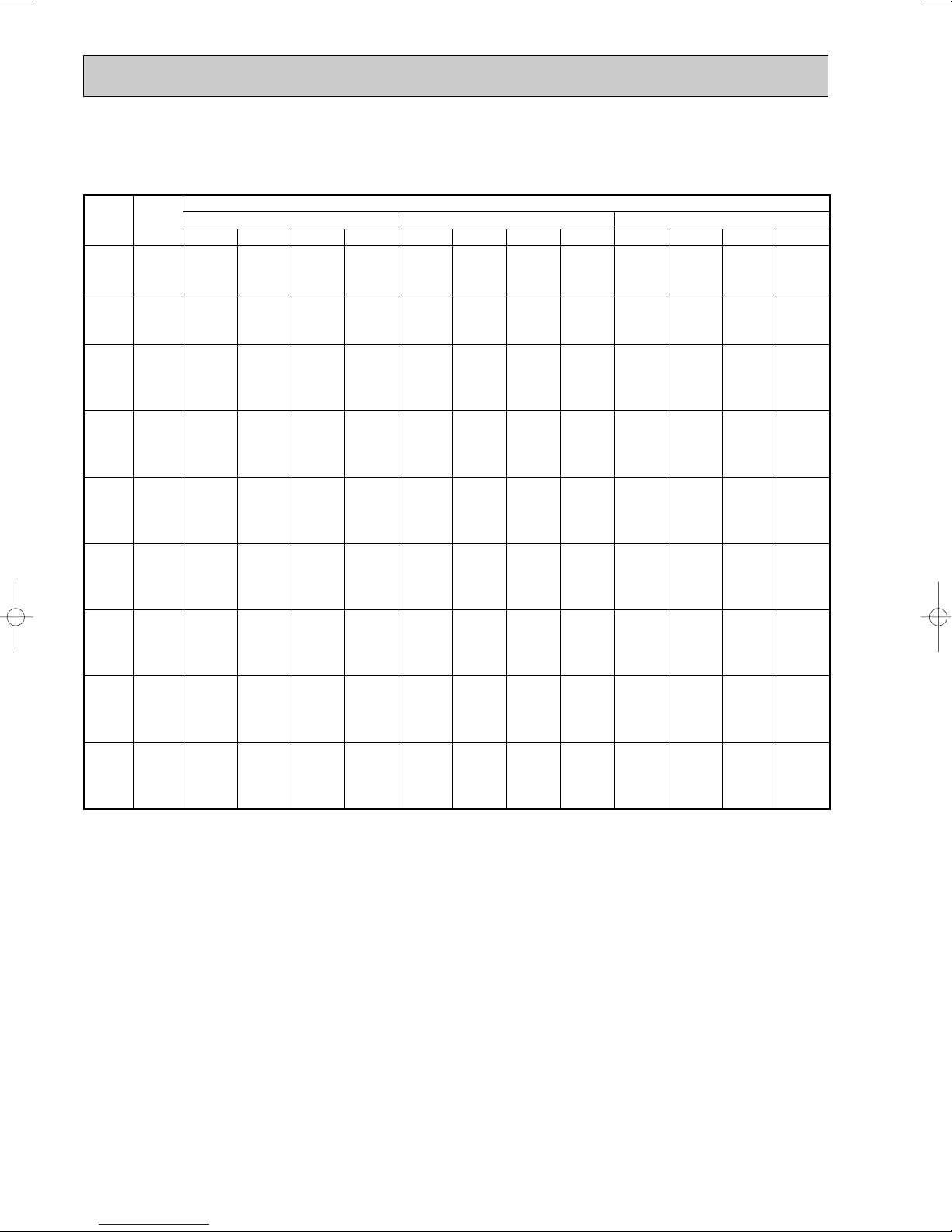
COOLING CAPACITY (2)
PLA-RP3AA.UK / PUHZ-RP3VHA
(230V)
NOTE:
CA: Capacity (W) SHC: Sensible heat capacity (W)
P.C.: Power consumption (kW) SHF: Sensible heat factor
20
20
20
22
22
22
24
24
24
24
26
26
26
26
27
27
27
27
28
28
28
28
30
30
30
30
32
32
32
32
34
34
34
34
16
18
20
16
18
20
16
18
20
22
16
18
20
22
16
18
20
22
16
18
20
22
16
18
20
22
16
18
20
22
16
18
20
22
6,319
6,816
7,384
6,319
6,816
7,384
6,319
6,816
7,384
7,952
6,319
6,816
7,384
7,952
6,319
6,816
7,384
7,952
6,319
6,816
7,384
7,952
6,319
6,816
7,384
7,952
6,319
6,816
7,384
7,952
6,319
6,816
7,384
7,952
4,044
3,544
2,954
4,550
4,090
3,544
5,055
4,635
4,135
3,499
5,561
5,180
4,726
4,135
5,813
5,453
5,021
4,453
6,066
5,725
5,316
4,771
6,319
6,271
5,907
5,407
6,319
6,816
6,498
6,044
6,319
6,816
7,089
6,680
0.64
0.52
0.40
0.72
0.60
0.48
0.80
0.68
0.56
0.44
0.88
0.76
0.64
0.52
0.92
0.80
0.68
0.56
0.96
0.84
0.72
0.60
1.00
0.92
0.80
0.68
1.00
1.00
0.88
0.76
1.00
1.00
0.96
0.84
1.89
1.94
1.99
1.89
1.94
1.99
1.89
1.94
1.99
2.03
1.89
1.94
1.99
2.03
1.89
1.94
1.99
2.03
1.89
1.94
1.99
2.03
1.89
1.94
1.99
2.03
1.89
1.94
1.99
2.03
1.89
1.94
1.99
2.03
6,035
6,603
7,100
6,035
6,603
7,100
6,035
6,603
7,100
7,668
6,035
6,603
7,100
7,668
6,035
6,603
7,100
7,668
6,035
6,603
7,100
7,668
6,035
6,603
7,100
7,668
6,035
6,603
7,100
7,668
6,035
6,603
7,100
7,668
3,862
3,434
2,840
4,345
3,962
3,408
4,828
4,490
3,976
3,374
5,311
5,018
4,544
3,987
5,552
5,282
4,828
4,294
5,794
5,547
5,112
4,601
6,035
6,075
5,680
5,214
6,035
6,603
6,248
5,828
6,035
6,603
6,816
6,441
0.64
0.52
0.40
0.72
0.60
0.48
0.80
0.68
0.56
0.44
0.88
0.76
0.64
0.52
0.92
0.80
0.68
0.56
0.96
0.84
0.72
0.60
1.00
0.92
0.80
0.68
1.00
1.00
0.88
0.76
1.00
1.00
0.96
0.84
2.03
2.09
2.13
2.03
2.09
2.13
2.03
2.09
2.13
2.19
2.03
2.09
2.13
2.19
2.03
2.09
2.13
2.19
2.03
2.09
2.13
2.19
2.03
2.09
2.13
2.19
2.03
2.09
2.13
2.19
2.03
2.09
2.13
2.19
5,751
6,177
6,674
5,751
6,177
6,674
5,751
6,177
6,674
7,242
5,751
6,177
6,674
7,242
5,751
6,177
6,674
7,242
5,751
6,177
6,674
7,242
5,751
6,177
6,674
7,242
5,751
6,177
6,674
7,242
5,751
6,177
6,674
7,242
3,681
3,212
2,670
4,141
3,706
3,204
4,601
4,200
3,737
3,186
5,061
4,695
4,271
3,766
5,291
4,942
4,538
4,056
5,521
5,189
4,805
4,345
5,751
5,683
5,339
4,925
5,751
6,177
5,873
5,504
5,751
6,177
6,407
6,083
0.64
0.52
0.40
0.72
0.60
0.48
0.80
0.68
0.56
0.44
0.88
0.76
0.64
0.52
0.92
0.80
0.68
0.56
0.96
0.84
0.72
0.60
1.00
0.92
0.80
0.68
1.00
1.00
0.88
0.76
1.00
1.00
0.96
0.84
2.20
2.25
2.29
2.20
2.25
2.29
2.20
2.25
2.29
2.32
2.20
2.25
2.29
2.32
2.20
2.25
2.29
2.32
2.20
2.25
2.29
2.32
2.20
2.25
2.29
2.32
2.20
2.25
2.29
2.32
2.20
2.25
2.29
2.32
CA
Indoor
intake air
D.B.(˚C)
Indoor
intake air
W.B.(˚C)
35 40 45
Outdoor intale air D.B.(˚C)
SHC SHF P.C. CA SHC SHF P.C. CA SHC SHF P.C.
12
COOLING CAPACITY (3)
PLA-RP4AA.UK / PUHZ-RP4VHA
Indoor
intake air
D.B.(˚C)
NOTE:
Indoor
intake air
W.B.(˚C)
20
20
20
22
22
22
24
24
24
24
26
26
26
26
27
27
27
27
28
28
28
28
30
30
30
30
32
32
32
32
34
34
34
34
16
18
20
16
18
20
16
18
20
22
16
18
20
22
16
18
20
22
16
18
20
22
16
18
20
22
16
18
20
22
16
18
20
22
CA: Capacity (W) SHC: Sensible heat capacity (W)
P.C.: Power consumption (kW) SHF: Sensible heat factor
CA
9,900
10,600
11,400
9,900
10,600
11,400
9,900
10,600
11,400
12,150
9,900
10,600
11,400
12,150
9,900
10,600
11,400
12,150
9,900
10,600
11,400
12,150
9,900
10,600
11,400
12,150
9,900
10,600
11,400
12,150
9,900
10,600
11,400
12,150
20 25 30
SHC SHF P.C. CA SHC SHF P.C. CA SHC SHF P.C.
6,435
5,618
4,674
7,227
6,466
5,586
8,019
7,314
6,498
5,468
8,811
8,162
7,410
6,440
9,207
8,586
7,866
6,926
9,603
9,010
8,322
7,412
9,900
9,858
9,234
8,384
9,900
10,600
10,146
9,356
9,900
10,600
11,058
10,328
0.65
0.53
0.41
0.73
0.61
0.49
0.81
0.69
0.57
0.45
0.89
0.77
0.65
0.53
0.93
0.81
0.69
0.57
0.97
0.85
0.73
0.61
1.00
0.93
0.81
0.69
1.00
1.00
0.89
0.77
1.00
1.00
0.97
0.85
2.42
2.47
2.55
2.42
2.47
2.55
2.42
2.47
2.55
2.61
2.42
2.47
2.55
2.61
2.42
2.47
2.55
2.61
2.42
2.47
2.55
2.61
2.42
2.47
2.55
2.61
2.42
2.47
2.55
2.61
2.42
2.47
2.55
2.61
Outdoor intale air D.B.(˚C)
9,600
10,300
11,150
9,600
10,300
11,150
9,600
10,300
11,150
11,900
9,600
10,300
11,150
11,900
9,600
10,300
11,150
11,900
9,600
10,300
11,150
11,900
9,600
10,300
11,150
11,900
9,600
10,300
11,150
11,900
9,600
10,300
11,150
11,900
6,240
5,459
4,572
7,008
6,283
5,464
7,776
7,107
6,356
5,355
8,544
7,931
7,248
6,307
8,928
8,343
7,694
6,783
9,312
8,755
8,140
7,259
9,600
9,579
9,032
8,211
9,600
10,300
9,924
9,163
9,600
10,300
10,816
10,115
0.65
0.53
0.41
0.73
0.61
0.49
0.81
0.69
0.57
0.45
0.89
0.77
0.65
0.53
0.93
0.81
0.69
0.57
0.97
0.85
0.73
0.61
1.00
0.93
0.81
0.69
1.00
1.00
0.89
0.77
1.00
1.00
0.97
0.85
2.56
2.61
2.67
2.56
2.61
2.67
2.56
2.61
2.67
2.76
2.56
2.61
2.67
2.76
2.56
2.61
2.67
2.76
2.56
2.61
2.67
2.76
2.56
2.61
2.67
2.76
2.56
2.61
2.67
2.76
2.56
2.61
2.67
2.76
9,300
9,950
10,850
9,300
9,950
10,850
9,300
9,950
10,850
11,600
9,300
9,950
10,850
11,600
9,300
9,950
10,850
11,600
9,300
9,950
10,850
11,600
9,300
9,950
10,850
11,600
9,300
9,950
10,850
11,600
9,300
9,950
10,850
11,600
6,045
5,274
4,449
6,789
6,070
5,317
7,533
6,866
6,185
5,220
8,277
7,662
7,053
6,148
8,649
8,060
7,487
6,612
9,021
8,458
7,921
7,076
9,300
9,254
8,789
8,004
9,300
9,950
9,657
8,932
9,300
9,950
10,525
9,860
0.65
0.53
0.41
0.73
0.61
0.49
0.81
0.69
0.57
0.45
0.89
0.77
0.65
0.53
0.93
0.81
0.69
0.57
0.97
0.85
0.73
0.61
1.00
0.93
0.81
0.69
1.00
1.00
0.89
0.77
1.00
1.00
0.97
0.85
(230V)
2.71
2.79
2.85
2.71
2.79
2.85
2.71
2.79
2.85
2.94
2.71
2.79
2.85
2.94
2.71
2.79
2.85
2.94
2.71
2.79
2.85
2.94
2.71
2.79
2.85
2.94
2.71
2.79
2.85
2.94
2.71
2.79
2.85
2.94
13
COOLING CAPACITY (4)
PLA-RP4AA.UK / PUHZ-RP4VHA
(230V)
NOTE:
CA: Capacity (W) SHC: Sensible heat capacity (W)
P.C.: Power consumption (kW) SHF: Sensible heat factor
20
20
20
22
22
22
24
24
24
24
26
26
26
26
27
27
27
27
28
28
28
28
30
30
30
30
32
32
32
32
34
34
34
34
16
18
20
16
18
20
16
18
20
22
16
18
20
22
16
18
20
22
16
18
20
22
16
18
20
22
16
18
20
22
16
18
20
22
8,900
9,600
10,400
8,900
9,600
10,400
8,900
9,600
10,400
11,200
8,900
9,600
10,400
11,200
8,900
9,600
10,400
11,200
8,900
9,600
10,400
11,200
8,900
9,600
10,400
11,200
8,900
9,600
10,400
11,200
8,900
9,600
10,400
11,200
5,785
5,088
4,264
6,497
5,856
5,096
7,209
6,624
5,928
5,040
7,921
7,392
6,760
5,936
8,277
7,776
7,176
6,384
8,633
8,160
7,592
6,832
8,900
8,928
8,424
7,728
8,900
9,600
9,256
8,624
8,900
9,600
10,088
9,520
0.65
0.53
0.41
0.73
0.61
0.49
0.81
0.69
0.57
0.45
0.89
0.77
0.65
0.53
0.93
0.81
0.69
0.57
0.97
0.85
0.73
0.61
1.00
0.93
0.81
0.69
1.00
1.00
0.89
0.77
1.00
1.00
0.97
0.85
2.91
2.98
3.06
2.91
2.98
3.06
2.91
2.98
3.06
3.12
2.91
2.98
3.06
3.12
2.91
2.98
3.06
3.12
2.91
2.98
3.06
3.12
2.91
2.98
3.06
3.12
2.91
2.98
3.06
3.12
2.91
2.98
3.06
3.12
8,500
9,300
10,000
8,500
9,300
10,000
8,500
9,300
10,000
10,800
8,500
9,300
10,000
10,800
8,500
9,300
10,000
10,800
8,500
9,300
10,000
10,800
8,500
9,300
10,000
10,800
8,500
9,300
10,000
10,800
8,500
9,300
10,000
10,800
5,525
4,929
4,100
6,205
5,673
4,900
6,885
6,417
5,700
4,860
7,565
7,161
6,500
5,724
7,905
7,533
6,900
6,156
8,245
7,905
7,300
6,588
8,500
8,649
8,100
7,452
8,500
9,300
8,900
8,316
8,500
9,300
9,700
9,180
0.65
0.53
0.41
0.73
0.61
0.49
0.81
0.69
0.57
0.45
0.89
0.77
0.65
0.53
0.93
0.81
0.69
0.57
0.97
0.85
0.73
0.61
1.00
0.93
0.81
0.69
1.00
1.00
0.89
0.77
1.00
1.00
0.97
0.85
3.12
3.21
3.27
3.12
3.21
3.27
3.12
3.21
3.27
3.36
3.12
3.21
3.27
3.36
3.12
3.21
3.27
3.36
3.12
3.21
3.27
3.36
3.12
3.21
3.27
3.36
3.12
3.21
3.27
3.36
3.12
3.21
3.27
3.36
8,100
8,700
9,400
8,100
8,700
9,400
8,100
8,700
9,400
10,200
8,100
8,700
9,400
10,200
8,100
8,700
9,400
10,200
8,100
8,700
9,400
10,200
8,100
8,700
9,400
10,200
8,100
8,700
9,400
10,200
8,100
8,700
9,400
10,200
5,265
4,611
3,854
5,913
5,307
4,606
6,561
6,003
5,358
4,590
7,209
6,699
6,110
5,406
7,533
7,047
6,486
5,814
7,857
7,395
6,862
6,222
8,100
8,091
7,614
7,038
8,100
8,700
8,366
7,854
8,100
8,700
9,118
8,670
0.65
0.53
0.41
0.73
0.61
0.49
0.81
0.69
0.57
0.45
0.89
0.77
0.65
0.53
0.93
0.81
0.69
0.57
0.97
0.85
0.73
0.61
1.00
0.93
0.81
0.69
1.00
1.00
0.89
0.77
1.00
1.00
0.97
0.85
3.38
3.45
3.51
3.38
3.45
3.51
3.38
3.45
3.51
3.58
3.38
3.45
3.51
3.58
3.38
3.45
3.51
3.58
3.38
3.45
3.51
3.58
3.38
3.45
3.51
3.58
3.38
3.45
3.51
3.58
3.38
3.45
3.51
3.58
CA
Indoor
intake air
D.B.(˚C)
Indoor
intake air
W.B.(˚C)
35 40 45
Outdoor intale air D.B.(˚C)
SHC SHF P.C. CA SHC SHF P.C. CA SHC SHF P.C.
14
COOLING CAPACITY (5)
PLA-RP5AA.UK / PUHZ-RP5VHA
Indoor
intake air
D.B.(˚C)
NOTE:
Indoor
intake air
W.B.(˚C)
20
20
20
22
22
22
24
24
24
24
26
26
26
26
27
27
27
27
28
28
28
28
30
30
30
30
32
32
32
32
34
34
34
34
16
18
20
16
18
20
16
18
20
22
16
18
20
22
16
18
20
22
16
18
20
22
16
18
20
22
16
18
20
22
16
18
20
22
CA: Capacity (W) SHC: Sensible heat capacity (W)
P.C.: Power consumption (kW) SHF: Sensible heat factor
CA
12,375
13,250
14,250
12,375
13,250
14,250
12,375
13,250
14,250
15,188
12,375
13,250
14,250
15,188
12,375
13,250
14,250
15,188
12,375
13,250
14,250
15,188
12,375
13,250
14,250
15,188
12,375
13,250
14,250
15,188
12,375
13,250
14,250
15,188
20 25 30
SHC SHF P.C. CA SHC SHF P.C. CA SHC SHF P.C.
7,920
6,890
5,700
8,910
7,950
6,840
9,900
9,010
7,980
6,683
10,890
10,070
9,120
7,898
11,385
10,600
9,690
8,505
11,880
11,130
10,260
9,113
12,375
12,190
11,400
10,328
12,375
13,250
12,540
11,543
12,375
13,250
13,680
12,758
0.64
0.52
0.40
0.72
0.60
0.48
0.80
0.68
0.56
0.44
0.88
0.76
0.64
0.52
0.92
0.80
0.68
0.56
0.96
0.84
0.72
0.60
1.00
0.92
0.80
0.68
1.00
1.00
0.88
0.76
1.00
1.00
0.96
0.84
3.11
3.17
3.27
3.11
3.17
3.27
3.11
3.17
3.27
3.35
3.11
3.17
3.27
3.35
3.11
3.17
3.27
3.35
3.11
3.17
3.27
3.35
3.11
3.17
3.27
3.35
3.11
3.17
3.27
3.35
3.11
3.17
3.27
3.35
Outdoor intale air D.B.(˚C)
12,000
12,875
13,938
12,000
12,875
13,938
12,000
12,875
13,938
14,875
12,000
12,875
13,938
14,875
12,000
12,875
13,938
14,875
12,000
12,875
13,938
14,875
12,000
12,875
13,938
14,875
12,000
12,875
13,938
14,875
12,000
12,875
13,938
14,875
7,680
6,695
5,575
8,640
7,725
6,690
9,600
8,755
7,805
6,545
10,560
9,785
8,920
7,735
11,040
10,300
9,478
8,330
11,520
10,815
10,035
8,925
12,000
11,845
11,150
10,115
12,000
12,875
12,265
11,305
12,000
12,875
13,380
12,495
0.64
0.52
0.40
0.72
0.60
0.48
0.80
0.68
0.56
0.44
0.88
0.76
0.64
0.52
0.92
0.80
0.68
0.56
0.96
0.84
0.72
0.60
1.00
0.92
0.80
0.68
1.00
1.00
0.88
0.76
1.00
1.00
0.96
0.84
3.29
3.35
3.42
3.29
3.35
3.42
3.29
3.35
3.42
3.54
3.29
3.35
3.42
3.54
3.29
3.35
3.42
3.54
3.29
3.35
3.42
3.54
3.29
3.35
3.42
3.54
3.29
3.35
3.42
3.54
3.29
3.35
3.42
3.54
11,625
12,438
13,563
11,625
12,438
13,563
11,625
12,438
13,563
14,500
11,625
12,438
13,563
14,500
11,625
12,438
13,563
14,500
11,625
12,438
13,563
14,500
11,625
12,438
13,563
14,500
11,625
12,438
13,563
14,500
11,625
12,438
13,563
14,500
7,440
6,468
5,425
8,370
7,463
6,510
9,300
8,458
7,595
6,380
10,230
9,453
8,680
7,540
10,695
9,950
9,223
8,120
11,160
10,448
9,765
8,700
11,625
11,443
10,850
9,860
11,625
12,438
11,935
11,020
11,625
12,438
13,020
12,180
0.64
0.52
0.40
0.72
0.60
0.48
0.80
0.68
0.56
0.44
0.88
0.76
0.64
0.52
0.92
0.80
0.68
0.56
0.96
0.84
0.72
0.60
1.00
0.92
0.80
0.68
1.00
1.00
0.88
0.76
1.00
1.00
0.96
0.84
(230V)
3.48
3.58
3.66
3.48
3.58
3.66
3.48
3.58
3.66
3.77
3.48
3.58
3.66
3.77
3.48
3.58
3.66
3.77
3.48
3.58
3.66
3.77
3.48
3.58
3.66
3.77
3.48
3.58
3.66
3.77
3.48
3.58
3.66
3.77
15
 Loading...