

Mitsubishi Electric PLA-RP50BA, PLA-RP35BA, PLA-RP60BA, PLA-RP71BA, PLA-RP100BA OPERATION MANUAL
...
Air-Conditioners
Indoor unit
Кондиционеры
ВНУТРЕННИЙ БЛОК
PLA-RP.BA Series
PLA-ZRP.BA Series
OPERATION MANUAL
For safe and correct use, please read this operation manual thoroughly before operating the air-conditioner unit.
BEDIENUNGSHANDBUCH
Zum sicheren und einwandfreien Gebrauch der Klimaanlage dieses Bedienungshandbuch vor Inbetriebnahme
gründlich durchlesen.
MANUEL D’UTILISATION
Pour une utilisation correcte sans risques, veuillez lire le manuel d’utilisation en entier avant de vous servir du
climatiseur.
BEDIENINGSHANDLEIDING
Voor een veilig en juist gebruik moet u deze bedieningshandleiding grondig doorlezen voordat u de airconditioner gebruikt.
MANUAL DE INSTRUCCIONES
Lea este manual de instrucciones hasta el fi nal antes de poner en marcha la unidad de aire acondicionado para
garantizar un uso seguro y correcto.
ISTRUZIONI DI FUNZIONAMENTO
Leggere attentamente questi istruzioni di funzionamento prima di avviare l’unità, per un uso corretto e sicuro
della stessa.
ΕΓΧΕΙΡΙΔΙΟ ΟΔΗΓΙΩΝ ΧΡΗΣΕΩΣ
Για ασφάλεια και σωστή χρήση, παρακαλείστε διαβάσετε προσεχτικά αυτό το εγχειρίδιο χρήσεως πριν θέσετε σε
λειτουργία τη μονάδα κλιματισμού.
MANUAL DE OPERAÇÃO
Para segurança e utilização correctas, leia atentamente o manual de operação antes de pôr a funcionar a unidade de ar condicionado.
FOR USER
FÜR BENUTZER
POUR L’UTILISATEUR
VOOR DE GEBRUIKER
PARA EL USUARIO
PER L’UTENTE
ΓΙΑ ΤΟΝ ΧΡΗΣΤΗ
PARA O UTILIZADOR
English
Deutsch
Français
Nederlands
Español
Italiano
Ελληνικά
Português
DRIFTSMANUAL
Læs venligst denne driftsmanual grundigt før airconditionanlægget betjenes af hensyn til sikker og korrekt brug.
DRIFTSMANUAL
Läs denna driftsmanual noga för säkert och korrekt bruk innan luftkonditioneringen används.
Işletme Elkitabı
Emniyetli ve doğru biçimde nasıl kullanılacağını öğrenmek için lütfen klima cihazını işletmeden önce bu
elkitabını dikkatle okuyunuz.
РУКОВОДСТВО ПО ЭКСПЛУАТАЦИИ
Для обеспечения правильного и безопасного использования следует ознакомиться с инструкциями,
указанными в данном руководстве по эксплуатации, тщательным образом до того, как приступать к
использованию кондиционера.
TIL BRUGER
FÖR ANVÄNDAREN
KULLANICI İÇİN
ДЛЯ ПОЛЬЗОВАТЕЛЯ
Dansk
Svenska
Türkçe
Русский
Contents
1. Safety Precautions . . . . . . . . . . . . . . . . . . . . . . . . . . . . . . . . .2
2. Parts Names . . . . . . . . . . . . . . . . . . . . . . . . . . . . . . . . . . . . . .3
3. Operation . . . . . . . . . . . . . . . . . . . . . . . . . . . . . . . . . . . . . . . .6
5. Care and Cleaning. . . . . . . . . . . . . . . . . . . . . . . . . . . . . . . . .10
6. Trouble Shooting . . . . . . . . . . . . . . . . . . . . . . . . . . . . . . . . . .11
7. Specifi cations . . . . . . . . . . . . . . . . . . . . . . . . . . . . . . . . . . . .12
4. Timer . . . . . . . . . . . . . . . . . . . . . . . . . . . . . . . . . . . . . . . . . . .10
This symbol mark is for EU countries only.
Note
Fig.1
Note:
The phrase “Wired remote controller” in this operation manual refers only to the PAR-31MAA.
If you need any information for the other remote controller, please refer to the instruction book included in this box.
This symbol mark is according to the directive 2012/19/EU Article 14 Information for users and Annex IX, and/or to the directive 2006/66/EC Article 20 Information for end-users and Annex II.
Your MITSUBISHI ELECTRIC product is designed and manufactured with high quality materials and components which can be
recycled and/or reused. This symbol means that electrical and electronic equipment, batteries and accumulators, at their end-oflife, should be disposed of separately from your household waste. If a chemical symbol is printed beneath the symbol (Fig. 1), this
chemical symbol means that the battery or accumulator contains a heavy metal at a certain concentration.
This will be indicated as follows: Hg: mercury (0,0005%), Cd: cadmium (0,002%), Pb: lead (0,004%)
In the European Union there are separate collection systems for used electrical and electronic products, batteries and accumulators.
Please, dispose of this equipment, batteries and accumulators correctly at your local community waste collection/recycling centre.
Please, help us to conserve the environment we live in!
1. Safety Precautions
► Before installing the unit, make sure you read all the “Safety
Precautions”.
► The “Safety Precautions” provide very important points re-
garding safety. Make sure you follow them.
► Please report to or take consent by the supply authority be-
fore connection to the system.
Symbols used in the text
Warning:
Describes precautions that should be observed to prevent danger
of injury or death to the user.
Caution:
Describes precautions that should be observed to prevent damage
to the unit.
Symbols used in the illustrations
: Indicates a part which must be grounded.
Warning:
• There appliances are not accessible to the general public.
• The unit must not be installed by the user. Ask the dealer or an
authorized company to install the unit. If the unit is installed improperly, water leakage, electric shock or fi re may result.
• Do not stand on, or place any items on the unit.
• Do not splash water over the unit and do not touch the unit with
wet hands. An electric shock may result.
• Do not spray combustible gas close to the unit. Fire may result.
• Do not place a gas heater or any other open-flame appliance
where it will be exposed to the air discharged from the unit. Incomplete combustion may result.
• Do not remove the front panel or the fan guard from the outdoor
unit when it is running.
• When you notice exceptionally abnormal noise or vibration, stop
operation, turn off the power switch, and contact your dealer.
• Never insert fi ngers, sticks etc. into the intakes or outlets.
• If you detect odd smells, stop using the unit, turn off the power
switch and consult your dealer. Otherwise, a breakdown, electric
shock or fi re may result.
• This air conditioner is NOT intended for use by children or infi rm
persons without supervision.
• Young children must be supervised to ensure that they do not
play with the air conditioner.
• If the refrigeration gas blows out or leaks, stop the operation of
the air conditioner, thoroughly ventilate the room, and contact
your dealer.
• This appliance is intended to be used by expert or trained users
in shops, in light industry and on farms, or for commercial use by
lay persons.
• This appliance can be used by children aged from 8 years and
above and persons with reduced physical, sensory or mental capabilities or lack of experience and knowledge if they have been
given supervision or instruction concerning use of the appliance
in a safe way and understand the hazards involved. Children shall
not play with the appliance. Cleaning and user maintenance shall
not be made by children without supervision.
• This appliance is not intended for use by persons (including children) with reduced physical, sensory or mental capabilities, or
lack of experience and knowledge, unless they have been given
supervision or instruction concerning use of the appliance by a
person responsible for their safety.
• Children should be supervised to ensure that they do not play
with the appliances.
• When installing or relocating, or servicing the air conditioner, use
only the specified refrigerant (R410A) to charge the refrigerant
lines. Do not mix it with any other refrigerant and do not allow air
to remain in the lines.
If air is mixed with the refrigerant, then it can be the cause of ab-
normal high pressure in the refrigerant line, and may result in an
explosion and other hazards.
The use of any refrigerant other than that specifi ed for the sys-
tem will cause mechanical failure or system malfunction or unit
breakdown. In the worst case, this could lead to a serious impediment to securing product safety.
Caution:
• Do not use any sharp object to push the buttons, as this may
damage the remote controller.
•
Never block or cover the indoor or outdoor unit’s intakes or outlets.
2
Disposing of the unit
When you need to dispose of the unit, consult your dealer.
2. Parts Names
■
Indoor Unit
PLA-(Z)RP.BA
Fan steps 4 steps
Vane Auto with swing
Louver –
Filter Long-life
Filter cleaning indication 2,500 hr
■
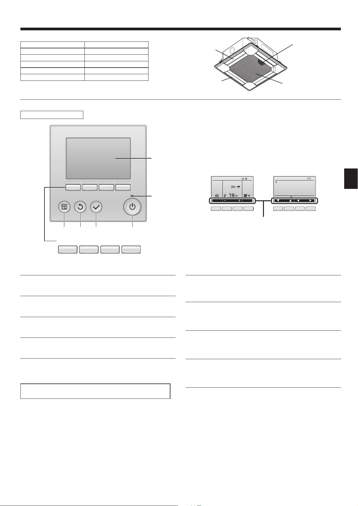
Wired Remote Controller
Controller interface
Air outlet
Vane
Filter
Air intake
The functions of the function buttons change depending on the
screen.
Refer to the button function guide that appears at the bottom of the
LCD for the functions they serve on a given screen.
When the system is centrally controlled, the button function guide
5
that corresponds to the locked button will not appear.
432 1
Function buttons
789 0
▌1 [ON/OFF] button
Press to turn ON/OFF the indoor unit.
▌2 [SELECT] button
Press to save the setting.
▌3 [RETURN] button
Press to return to the previous screen.
▌4 [MENU] button
Press to bring up the Main menu.
Main display Main menu
Room
Set temp.
6
Cool Auto
Mode Temp. Fan
Fri
Main
Main menu
Vane·Louver·Vent. (Lossnay)
High power
Timer
Weekly timer
OU silent mode
Main display:
Cursor Page
789 0 78 90
Function guide
▌6 ON/OFF lamp
This lamp lights up in green while the unit is in operation. It blinks while
the remote controller is starting up or when there is an error.
▌7 Function button [F1]
Main display: Press to change the operation mode.
Main menu: Press to move the cursor down.
▌8 Function button [F2]
Main display: Press to decrease temperature.
Main menu: Press to move the cursor up.
▌5 Backlit LCD
Operation settings will appear.
When the backlight is off, pressing any button turns the backlight on
and it will stay lit for a certain period of time depending on the screen.
When the backlight is off, pressing any button turns the backlight on
and does not perform its function. (except for the [ON/OFF] button)
▌9 Function button [F3]
Main display: Press to increase temperature.
Main menu: Press to go to the previous page.
▌0 Function button [F4]
Main display: Press to change the fan speed.
Main menu: Press to go to the next page.
3
2. Parts Names
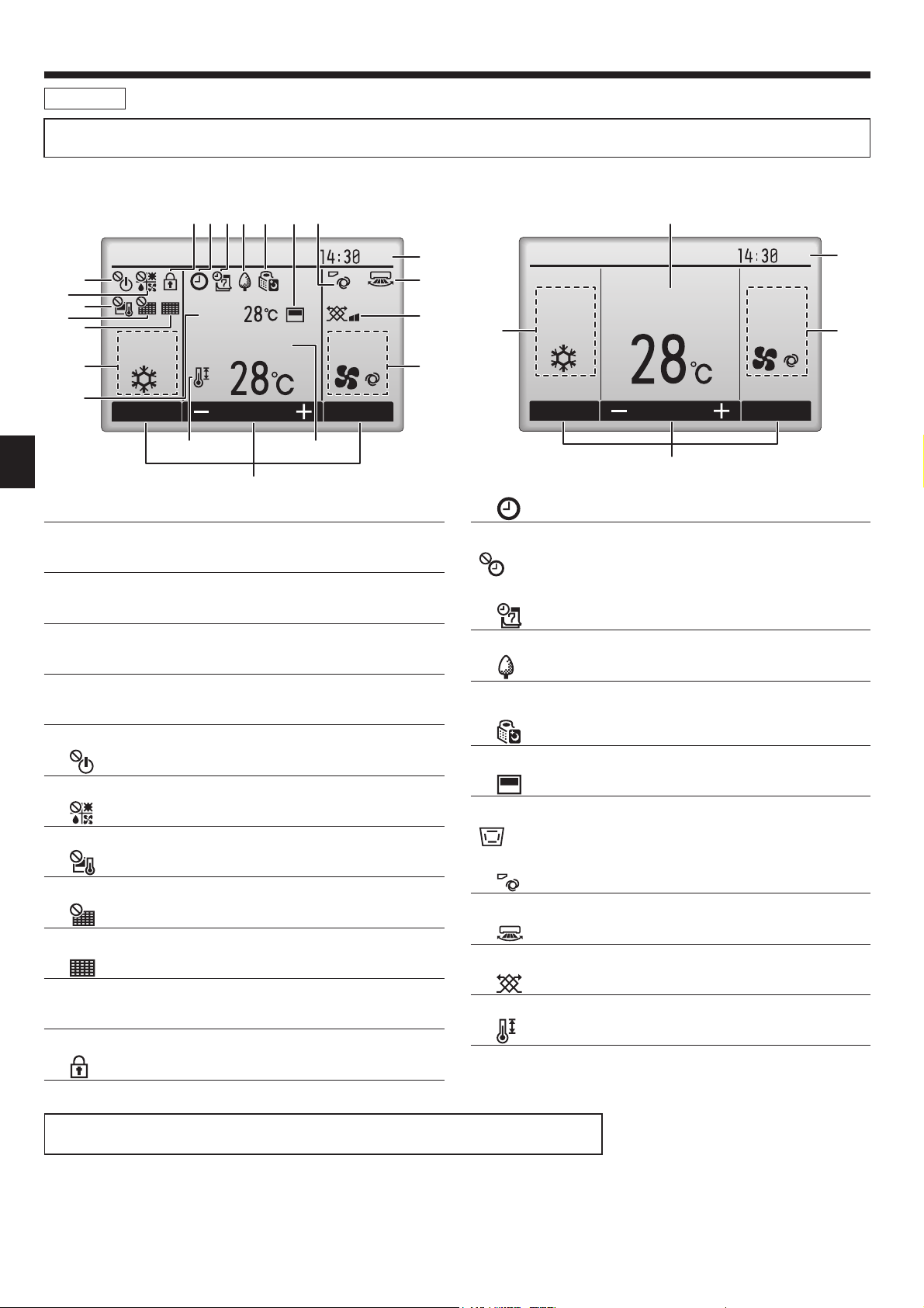
Display
The main display can be displayed in two different modes: “Full” and “Basic”. The factory setting is “Full”. To switch to the “Basic” mode, change the
setting on the Main display setting. (Refer to operation manual included with remote controller.)
<Full mode>
* All icons are displayed for explanation.
2345 6 7 8
6
7
8
9
0
Cool Auto
Room
Set temp.
1
1
Mode Temp. Fan
!
5
▌1 Operation mode
Indoor unit operation mode appears here.
▌2 Preset temperature
Preset temperature appears here.
▌3 Clock (See the Installation Manual.)
Current time appears here.
<Basic mode>
2
Fri
3
Fri
3
9
)
1
Cool
AutoSet temp.
4
4
Mode Temp. Fan
2
5
▌3
Appears when the On/Off timer, Night setback, or Auto-off timer function is enabled.
appears when the timer is disabled by the centralized control
system.
▌4
Appears when the Weekly timer is enabled.
▌4 Fan speed
Fan speed setting appears here.
▌5 Button function guide
Functions of the corresponding buttons appear here.
▌6
Appears when the ON/OFF operation is centrally controlled.
▌7
Appears when the operation mode is centrally controlled.
▌8
Appears when the preset temperature is centrally controlled.
▌9
Appears when the fi lter reset function is centrally controlled.
▌0
Indicates when fi lter needs maintenance.
▌1 Room temperature (See the Installation Manual.)
Current room temperature appears here.
▌2
Appears when the buttons are locked.
▌5
Appears while the units are operated in the energy-save mode. (Will
not appear on some models of indoor units)
▌6
Appears while the outdoor units are operated in the silent mode.
▌7
Appears when the built-in thermistor on the remote controller is activated to monitor the room temperature (1).
appears when the thermistor on the indoor unit is activated to
monitor the room temperature.
▌8
Indicates the vane setting.
▌9
Indicates the louver setting.
▌)
Indicates the ventilation setting.
▌!
Appears when the preset temperature range is restricted.
Most settings (except ON/OFF, mode, fan speed, temperature) can be made from the Menu screen.
(Refer to operation manual included with remote controller.)
4

2. Parts Names
■
Wireless Remote-Controller
Transmission area
Remote controller display
* For explanation purposes, all of the items
that appear in the display are shown.
* All items are displayed when the Reset but-
ton is pressed.
ON/OFF button
Set Temperature buttons
Fan Speed button (Changes fan speed)
Airfl ow button (Changes up/down airfl ow direction)
Mode button (Changes operation mode)
Check button
Test Run button
Transmission indicator
Timer indicator
Operation areas
Timer Off button
Timer On button
Hour button
Minute button
Set Time button (Sets the time)
Louver button (Changes left/right airfl ow direction)
Reset button
Note (Only for wireless remote controller):
■
When using the wireless remote controller, point it towards the receiver on the indoor unit.
■
If the remote controller is operated within approximately 2 minutes after power is supplied to the
indoor unit, the indoor unit may beep twice as the unit is performing the initial automatic check.
■
The indoor unit beeps to confi rm that the signal transmitted from the remote controller has been
received. Signals can be received up to approximately 7 meters in a direct line from the indoor
unit in an area 45° to the left and right of the unit. However, illumination such as fl uorescent
lights and strong light can affect the ability of the indoor unit to receive signals.
■
If the operation lamp near the receiver on the indoor unit is blinking, the unit needs to be in-
spected. Consult your dealer for service.
■
Handle the remote controller carefully! Do not drop the remote controller or subject it to strong
shocks. In addition, do not get the remote controller wet or leave it in a location with high humidity.
■
To avoid misplacing the remote controller, install the holder included with the remote controller
on a wall and be sure to always place the remote controller in the holder after use.
■
Outdoor unit
Power
Ref. Pipes
Indoor-Outdoor
Connection wire
Battery installation/replacement
1. Remove the top cover, insert 2 AAA batteries, and then install the top cover.
1
2
Top cover
2. Press the Reset button.
3
Two AAA batteries
Insert the negative (–)
end of each battery fi rst.
Install the batteries in
the correct directions
(+, –)!
Press the Reset button
with an object that has
a narrow end.
Service Panel
Earth
5
3. Operation
■
About the operation method, refer to the operation manual that comes with each remote controller.
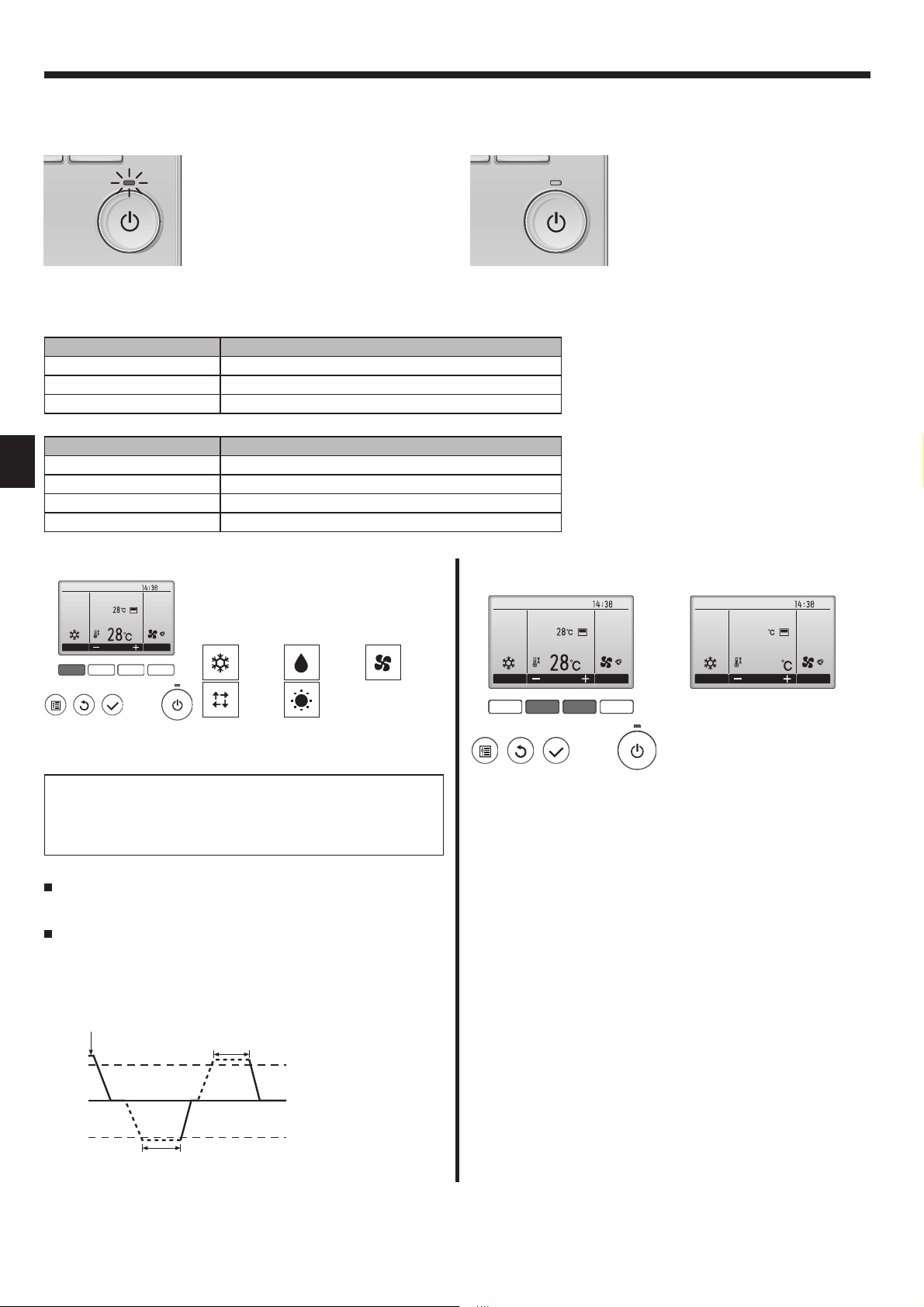
3.1. Turning ON/OFF
[ON] [OFF]
Press the [ON/OFF] button.
The ON/OFF lamp will light up in
green, and the operation will start.
Note:
Even if you press the ON/OFF button immediately after shutting down the operation is progress, the air conditioner will not start for about 3 minutes.
This is to prevent the internal components from being damaged.
■
Operation status memory
Remote controller setting
Operation mode Operation mode before the power was turned off
Preset temperature Preset temperature before the power was turned off
Fan speed Fan speed before the power was turned off
■
Settable preset temperature range
Operation mode Preset temperature range
Cool/Dry 19 ~ 30 ºC
Heat 17 ~ 28 ºC
Auto 19 ~ 28 ºC
Fan/Ventilation Not settable
Press the [ON/OFF] button again.
The ON/OFF lamp will come off, and
the operation will stop.
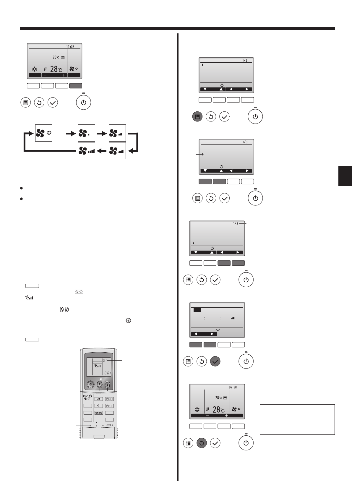
3.2. Mode Selection
Press the [F1] button to go through the op-
Fri
Room
Cool
Mode Temp. Fan
F1 F2 F3 F4
AutoSet temp.
What the blinking mode icon means
The mode icon will blink when other indoor units in the same refrigerant system (connected to the same outdoor unit) are already operated
in a different mode. In this case, the rest of the unit in the same group
can only be operated in the same mode.
Automatic operation
According to a set temperature, cooling operation starts if the room
temperature is too hot and heating operation starts if the room temperature is too cold.
During automatic operation, if the room temperature changes and
remains 2.0 °C or more above the set temperature for 15 minutes, the
air conditioner switches to cool mode. In the same way, if the room
temperature remains 2.0 °C or more below the set temperature for
15 minutes, the air conditioner switches to heat mode.
Cool mode
eration modes in the order of “Cool”, “Dry”,
“Fan”, “Auto”, and “Heat”. Select the desired
operation mode.
Cool Dry Fan
Auto Heat
• Operation modes that are not available
to the connected outdoor unit models will
not appear on the display.
15 minutes (switches
from heating to cooling)
Set temperature +2.0°C
3.3. Temperature setting
<Cool, Dry, Heat, and Auto>
Fri
Room
Cool
Mode Temp. Fan
F1 F2 F3 F4
AutoSet temp.
(Centigrade in 0.5-degree increments)
Room
Cool
Mode Temp. Fan
28.5
28.5
Example display
Press the [F2] button to decrease the preset temperature, and press the
[F3] button to increase.
• Refer to the table on page 6 for the settable temperature range for different operation modes.
• Preset temperature range cannot be set for Fan/Ventilation operation.
• Preset temperature will be displayed either in Centigrade in 0.5- or
1-degree increments, or in Fahrenheit, depending on the indoor unit
model and the display mode setting on the remote controller.
Fri
AutoSet temp.
Set temperature
Set temperature -2.0°C
15 minutes (switches
from cooling to heating)
6
3. Operation
3.4. Fan speed setting
Fri
Room
Cool
Mode Temp. Fan
F1 F2 F3 F4
Press the [F4] button to go through the fan speeds in the following order.
• The available fan speeds depend on the models of connected indoor
units.
Note:
The number of available fan speeds depends on the type of unit
connected. Note also that some units do not provide an “Auto” setting.
In the following cases, the actual fan speed generated by the unit will differ
from the speed shown the remote controller display.
1. While the display is showing “STAND BY” or “DEFROST”.
2. When the temperature of the heat exchanger is low in the heat mode.
(e.g. immediately after heat operation starts)
3. In HEAT mode, when room temperature is higher than the temperature
setting.
4. When the unit is in DRY mode.
■ Automatic fan speed setting (For wireless remote controller)
It is necessary to set for wireless remote controller only when automatic
fan speed is not set at default setting.
It is not necessary to set for wired remote controller with automatic fan
speed at default setting.
1 Press the SET button with something sharp at the end.
Operate when display of remote controller is off.
MODEL SELECT
blinks and Model No. is lighted A.
2 Press the AUTO STOP button.
blinks and setting No. is lighted B.
(Setting No.01: without automatic fan speed)
3 Press the temp. buttons to set the setting No.02.
(Setting No.02: with automatic fan speed)
If you mistook the operation, press the ON/OFF button and operate
again from procedure 2.
4 Press the SET button with something sharp at the end.
MODEL SELECT
and Model No. are lighted for 3 seconds, then turned off.
AutoSet temp.
Auto
3.5. Airfl ow direction setting
3.5.1 Navigating through the Main menu
<Accessing the Main menu>
Main
Main menu
Vane·Louver·Vent. (Lossnay)
High power
Timer
Weekly timer
OU silent mode
Main display:
Cursor Page
F1 F2 F3 F4
<Item selection>
Main
Main menu
Vane·Louver·Vent. (Lossnay)
Cursor
High power
Timer
Weekly timer
OU silent mode
Main display:
Cursor Page
F1 F2 F3 F4
<Navigating through the pages>
Main
Main menu
Vane·Louver·Vent. (Lossnay)
High power
Timer
Weekly timer
OU silent mode
Main display:
Cursor Page
F1 F2 F3 F4
<Saving the settings>
OU silent mode
Mon Tue Wed Thu Fri Sat Sun
Start Stop Silent
-
Setting display:
day
Press the [MENU] button.
The Main menu will appear.
Press [F1] to move the cursor down.
Press [F2] to move the cursor up.
page
Press [F3] to go to the previous
page.
Press [F4] to go to the next page.
Select the desired item, and press
the [SELECT] button.
The screen to set the selected item
will appear.
14
MODEL SELECT
ON/OFF TEMP
FAN
VANE
MODE
CHECK
LOUVER
TEST RUN
RESETSET CLOCK
AUTO STOP
AUTO START
h
min
F1 F2 F3 F4
B
A
3
2
<Exiting the Main menu screen>
Fri
Room
Cool
Mode Temp. Fan
F1 F2 F3 F4
AutoSet temp.
Press the [RETURN] button to exit
the Main menu and return to the
Main display.
If no buttons are touched for 10
minutes, the screen will automatically return to the Main display.
Any settings that have not been
saved will be lost.
7
3. Operation
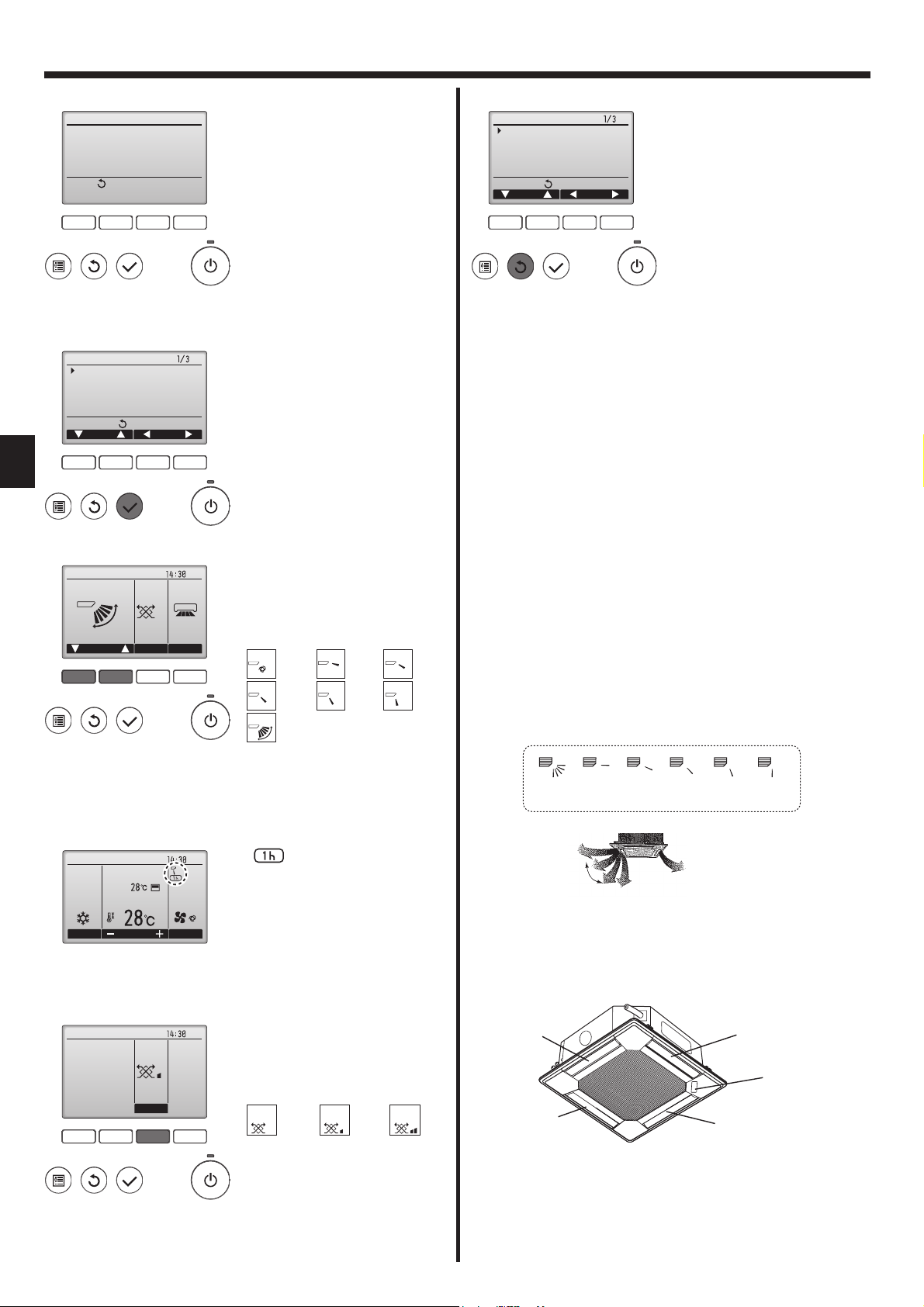
<Display of unsupported functions>
Title
Not available
Unsupported function
Return:
F1 F2 F3 F4
3.5.2 Vane·Vent. (Lossnay)
<Accessing the menu>
Main
Main menu
Vane·Louver·Vent. (Lossnay)
High power
Timer
Weekly timer
OU silent mode
Main display:
Cursor Page
F1 F2 F3 F4
<Vane setting>
Fri
Swing Off Off
LouverVent.Van e
F1 F2 F3 F4
The message at left will appear if
the user selects a function not supported by the corresponding indoor
unit model.
Select "Vane·Louver·Vent. (Lossnay)" from the Main menu (refer to
page 7), and press the [SELECT]
button.
Press the [F1] or [F2] button to go
through the vane setting options:
"Auto", "Step 1", "Step 2", "Step 3",
"Step 4", "Step 5" and "Swing".
Select the desired setting.
Auto
Swing
Auto
Swing
Step 1 Step 2
Step 4Step 3
Step 5
<Returning to the Main menu>
Main
Main menu
Vane·Louver·Vent. (Lossnay)
High power
Timer
Weekly timer
OU silent mode
Main display:
Cursor Page
F1 F2 F3 F4
Press the [RETURN] button to go
back to the Main menu.
Note:
●
During swing operation, the directional indication on the screen
does not change in sync with the directional vanes on the unit.
● Available directions depend on the type of unit connected.
In the following cases, the actual air direction will differ from the
●
direction indicated on the remote controller display.
1. While the display is in “STAND BY” or “DEFROST” states.
2. Immediately after starting heat mode (while the system is wait-
ing for the mode change to take effect).
3. In heat mode, when room temperature is higher than the tem-
perature setting.
< How to set the fi xed up/down air direction (Only for
wired remote controller) >
Note:
● This function cannot be set depending on the outdoor unit to be
connected.
• For PLA-(Z)RP.BA series, only the particular outlet can be fi xed to
certain direction with the procedures below. Once fi xed, only the set
outlet is fi xed every time air conditioner is turned on. (Other outlets
follow UP/DOWN air direction setting of remote controller.)
■
Explanation of word
• “Refrigerant address No.” and “Unit No.” are the numbers given to
each air conditioner.
• “Outlet No.” is the number given to each outlet of air conditioner.
(Refer to the illustration below.)
• “Up/Down air direction” is the direction (angle) to fi x.
Room
Cool
Mode Temp. Fan
<Vent. setting>
F1 F2 F3 F4
Low
Vent.
Select "Swing" to move the vanes
up and down automatically.
When set to "Step 1" through "Step
5", the vane will be fi xed at the se-
Reset 1
horizontal
2345
lected angle.
under the vane setting icon
Fri
•
This icon will appear when the
AutoSet temp.
vane is set to "Step 2" to "Step 5"
and the fan operates at "Mid 1"
to "Low" speed during cooling or
dry operation (depends on the
model).
The icon will go off in an hour, and
Horizontal airfl ow
Remote controller setting
The airfl ow direction of this outlet
is controlled by the airfl ow direc-
tion setting of remote controller.
Downward
Fixed
The airfl ow direction of this outlet is fi xed
in particular direction.
* When it is cold because of direct
airfl ow, the airfl ow direction can be fi xed
horizontally to avoid direct airfl ow.
the vane setting will automatically
change.
Fri
Press the [F3] button to go through
the ventilation setting options in the
Outlet No.3
order of "Off", "Low", and "High".
* Settable only when LOSSNAY
unit is connected.
Off Low High
Off Low High
Outlet No.2
Outlet No.4
MITSUBISHI
ELECTRIC
label
Outlet No.1
• The fan on some models of indoor units may be interlocked
Note: “0” indicates all outlets.
with certain models of ventilation
units.
8
3. Operation
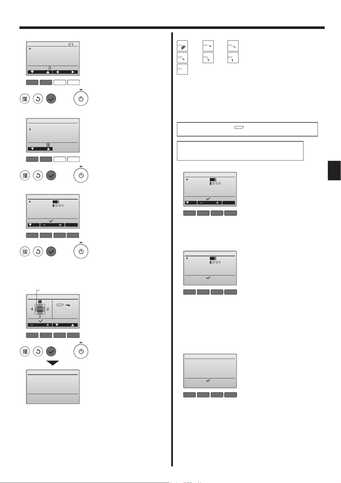
■
Manual vane angle
Main
Main menu
Maintenance
Initial setting
Service
Main display:
Cursor Page
F1 F2 F3 F4
Maintenance menu
Auto descending panel
Manual vane angle
Main menu:
Cursor
F1 F2 F3 F4
Manual vane angle
Ref. address
Unit No.
Identify unit Check button
Input display:
Cur. Address Check
F1 F2 F3 F4
MITSUBISHI ELECTRIC
LABEL
Manual vane angle
Select:
Outlet Angle
F1 F2 F3 F4
Manual vane angle
Setting
Select "Maintenance" from the
1
Main menu (refer to page 7), and
press the [SELECT] button.
Select "Manual vane angle" with
2
the [F1] or [F2] button, and press
the [SELECT] button.
Move the cursor to "Ref. address"
3
or "Unit No." with the [F1] button
to select.
Select the refrigerant address and
the unit number for the units to
whose vanes are to be fixed, with
the [F2] or [F3] button, and press
the [SELECT] button.
• Ref. address: Refrigerant address
• Unit No.: 1, 2, 3, 4
Press the [F4] button to confi rm the
unit.
The vane of only the target indoor
unit is pointing downward.
The current vane setting will ap-
4
pear.
Select the desired outlets from 1
through 4 with the [F1] or [F2] button.
• Outlet: "1", "2", "3", "4" and "1, 2, 3,
4, (all outlets)"
Press the [F3] or [F4] button to go
through the option in the order of
"No setting (reset)," "Step 1", "Step
2", "Step 3", "Step 4" and "Step 5".
Select the desired setting.
■
Vane setting
No setting
All outlets
Step 1 Step 2
Step 4Step 3
Step 5
Press the [SELECT] button to save the settings.
A screen will appear that indicates the setting information is being transmitted.
The setting changes will be made to the selected outlet.
The screen will automatically return to the one shown above (step 4)
when the transmission is completed.
Make the settings for other outlets, following the same procedures.
If all outlets are selected,
will be displayed the next time
the unit goes into operation.
Navigating through the screens
• To go back to the Main menu ................ [MENU] button
• To return to the previous screen .......... [RETURN] button
■ Confi rmation procedure
Manual vane angle
Ref. address
Unit No.
Identify unit Check button
Input display:
Cur. Address Check
F1 F2 F3 F4
Manual vane angle
Ref. address
Unit No.
The air conditioner with the
vane pointing downward is
the target air conditioner.
Input display:
F1 F2 F3 F4
Manual vane angle
There is no response from
the target device.
Confirm the state of the air
conditioner.
Input display:
F1 F2 F3 F4
First, confi rm by setting “Ref. ad-
1
dress” to 0 and “Unit No.” to 1.
• Move the cursor to "Ref. address"
or "Unit No." with the [F1] button
to select.
• Select the refrigerant address and
the unit number for the units to
whose vanes are to be fi xed, with
the [F2] or [F3] button, and press
the [SELECT] button.
• Ref. address: Refrigerant address
• Unit No.: 1, 2, 3, 4
Press the [F4] button to confi rm the
unit.
Change the “Unit No.” in order
2
and check each unit.
• Press the [F1] button to select “Unit
No.”.
Press the [F2] or [F3] button to
change the “Unit No.” to the unit
that you want to check, and then
press the [F4] button.
• After pressing the [F4] button, wait
approximately 15 seconds, and
then check the current state of the
air conditioner.
→ The vane is pointing downward.
→ This air conditioner is displayed
on the remote controller.
→ All outlets are closed. → Press
the [RETURN] button and continue the operation from the beginning.
→ The messages shown to the
left are displayed. → The target
device does not exist at this refrigerant address.
• Press the [RETURN] button to return to the initial screen.
Change the “Ref. address” to the
3
next number.
• Refer to step 1 to change the “Ref.
address” and continue with the
confi rmation.
9
 Loading...