

Mitsubishi PLA-RP50BA, PLA-RP100BA, PLA-RP60BA, PLA-RP71BA, PLA-RP125BA Service Manual
...
SERVICE MANUAL
SPLIT-TYPE, HEAT PUMP AIR CONDITIONERS
SPLIT-TYPE, AIR CONDITIONERS
NOTE:
• This manual describes only
service data of the indoor
units.
• RoHS compliant products
have <G> mark on the spec
name plate.
CONTENTS
1. TECHNICAL CHANGES
..................................
2
2. REFERENCE MANUAL
..................................
3
3. SAFETY PRECAUTION
..................................
4
4. PARTS NAMES AND FUNCTIONS
................
5
5. SPECIFICATIONS
.........................................
13
6. NOISE CRITERION CURVES
.......................
17
7. OUTLINES AND DIMENSIONS
.....................
19
8. WIRING DIAGRAM
........................................
20
9. REFRIGERANT SYSTEM DIAGRAM
...........
22
10. TROUBLESHOOTING
...................................
23
11. SPECIAL FUNCTION
....................................
39
12. DISASSEMBLY PROCEDURE
......................
49
WIRED REMOTE
CONTROLLER
WIRELESS REMOTE
CONTROLLER
ON/OFF TEMP
INDOOR UNIT
Model name
indication
PARTS CATALOG (OCB412)
No. OCH412
REVISED EDITION-G
August 2013
• Please void OCH412
REVISED EDITION-F.
Revision:
• Added connectable outdoor unit
SUZ-KA35/50/60/71VA4.TH
in REVISED EDITION-G.
• Some descriptions have been
modified.
Indoor unit
[Model Name]
PLA-RP35BA
PLA-RP50BA
PLA-RP60BA
PLA-RP71BA
PLA-RP100BA
PLA-RP125BA
PLA-RP140BA
PLA-RP71BA2
PLA-RP100BA2
PLA-RP125BA2
PLA-RP140BA2
[Service Ref.]
Refer to page 2.
ON/OFF
TEMP.
2
1
TECHNICAL CHANGES
PLA-RP35BA1.UK PLA-RP35BA#2.UK
PLA-RP50BA1.UK PLA-RP50BA#2.UK
PLA-RP60BA1.UK PLA-RP60BA#2.UK
PLA-RP71BA1.UK PLA-RP71BA#2.UK
PLA-RP100BA.UK PLA-RP100BA#2.UK
PLA-RP125BA.UK PLA-RP125BA#2.UK
PLA-RP140BA.UK PLA-RP140BA#2.UK
INDOOR CONTROLELR BOARD (I.B.) has been changed. (S/W version up)
PLA-RP35BA.UK PLA-RP35BA1.UK
PLA-RP50BA.UK PLA-RP50BA1.UK
PLA-RP60BA.UK PLA-RP60BA1.UK
PLA-RP71BA.UK PLA-RP71BA1.UK
FAN MOTOR (MF) has been changed.
TURBO FAN, NUT and WASHER have been changed.
PLA-RP140BA#2.UK PLA-RP140BA2.UK
HEAT EXCHANGER has been changed.
INDOOR CONTROLELR BOARD (I.B.) has been changed. (S/W version up)
PLP-6BAJ (Automatic filter elevation panel, option)
The controller board (I.B) has been changed. (only for the panel but not for the service part)
[Service Ref.]
PLA-RP35BA.UK
PLA-RP35BA1.UK
PLA-RP35BA#2.UK
PLA-RP35BAR3.UK
PLA-RP50BA.UK
PLA-RP50BA1.UK
PLA-RP50BA#2.UK
PLA-RP50BAR3.UK
PLA-RP60BA.UK
PLA-RP60BA1.UK
PLA-RP60BA#2.UK
PLA-RP60BAR3.UK
PLA-RP71BA.UK
PLA-RP71BA1.UK
PLA-RP71BA#2.UK
PLA-RP71BAR3.UK
PLA-RP100BA.UK
PLA-RP100BA#2.UK
PLA-RP125BA.UK
PLA-RP125BA#2.UK
PLA-RP140BA.UK
PLA-RP140BA#2.UK
PLA-RP35BA#2.UK PLA-RP35BAR3.UK
PLA-RP50BA#2.UK PLA-RP50BAR3.UK
PLA-RP60BA#2.UK PLA-RP60BAR3.UK
PLA-RP71BA#2.UK PLA-RP71BAR3.UK
INDOOR CONTROLLER BOARD (I.B.) has been changed. (S/W version up)
PLA-RP71BA2.UK
PLA-RP100BA2.UK
PLA-RP125BA2.UK
PLA-RP140BA2.UK
OCH412G
3
2
REFERENCE MANUAL
OUTDOOR UNIT’S SERVICE MANUAL
Service Ref.
SUZ-KA
35/50/60/71VA3.TH
PUHZ-RP200/250YHA
(1)(2)
SUZ-KA·VA(1).TH
SUZ-KA.VAR2.TH
Service Manual No.
OCH530/OCB530
OC338
PUHZ-P200/250YHA(3)
OCH424/OCB424
OC374
OC379
PUHZ-HRP71/100VHA(2)
PUHZ-HRP100/125YHA(2)
OCH425/OCB425
OCH428/OCB428
OCH451/OCB451
OCH415/OCB415
MXZ-8A140VA
2/VA3
PUHZ-P100/125/140VHA2(1).UK
PUHZ-P100/125/140VHA3(R1).UK
OC322
OC316
PUHZ-RP35/50/60/71/100/125/140VHA2
(1)
PUHZ-RP125/140VHA2#2
PUHZ-RP35/50/60/71/100VHA3(#1)
PUHZ-RP100/125/140YHA2
(1)
PUHZ-RP125/140YHA2#2
PUHZ-RP100YHA3(#1)
PU(H)-P71/100VHA
(1).UK
PU(H)-P71/100VHA#2.UK
PU(H)-P71/100VHAR3.UK
PU(H)-P71/100/125/140YHA
(1).UK
PU(H)-P71/100/125/140YHA㸡2.UK
PU(H)-P71/100/125/140YHAR3.UK
PUHZ-RP35/50/60/71VHA4
PUHZ-RP100/125/140VKA
PUHZ-RP100/125/140/200/250YKA
PUHZ-RP200/250YHA2
SUZ-KA35/50/60/71VA4.TH
OCH545/OCB545
OCH412G
4
SAFETY PRECAUTION
3
Cautions for units utilising refrigerant R410A
3-2. CAUTIONS RELATED TO NEW REFRIGERANT
Use new refrigerant pipes.
Store the piping indoors, and both ends of the
piping sealed until just before brazing.
(Leave elbow joints, etc. in their packaging.)
In case of using the existing pipes for R22, be careful with
the followings.
· For RP100, 125 and 140, be sure to perform replace ment operation before test run.
· Change flare nut to the one provided with this product.
Use a newly flared pipe.
· Avoid using thin pipes.
Charge refrigerant from liquid phase of gas
cylinder.
If the refrigerant is charged from gas phase, composition
change may occur in refrigerant and the efficiency will be
lowered.
Do not use refrigerant other than R410A.
If other refrigerant (R22 etc.) is used, chlorine in refrigerant can cause deterioration of refrigerant oil etc.
Use a vacuum pump with a reverse flow check
valve.
Vacuum pump oil may flow back into refrigerant cycle and
that can cause deterioration of refrigerant oil etc.
Use the following tools specifically designed for
use with R410A refrigerant.
The following tools are necessary to use R410A refrigerant.
Handle tools with care.
If dirt, dust or moisture enters into refrigerant cycle, that can
cause deterioration of refrigerant oil or malfunction of compressor.
Do not use a charging cylinder.
If a charging cylinder is used, the composition of refrigerant will change and the efficiency will be lowered.
Flare tool
Electronic refrigerant
charging scale
Vacuum pump adaptor
Size adjustment gauge
Gauge manifold
Torque wrench
Gas leak detector
Charge hose
Tools for R410A
Contamination inside refrigerant piping can cause deterioration of refrigerant oil etc.
If dirt, dust or moisture enters into refrigerant cycle, that can
cause deterioration of refrigerant oil or malfunction of compressor.
If large amount of mineral oil enters, that can cause deterioration of refrigerant oil etc.
Ventilate the room if refrigerant leaks during
operation. If refrigerant comes into contact with
a flame, poisonous gases will be released.
Never use any refrigerant other than that specified.
Doing so may cause a burst, an explosion, or fire when the
unit is being used, serviced, or disposed of.
Correct refrigerant is specified in the manuals and on the
spec labels provided with our products.
We will not be held responsible for mechanical failure,
system malfunction, unit breakdown or accidents caused
by failure to follow the instructions.
Use the specified refrigerant only.
Make sure that the inside and outside of refrigerant piping is clean and it has no contaminants
such as sulfur, oxides, dirt, shaving particles, etc,
which are hazard to refrigerant cycle.
In addition, use pipes with specified thickness.
The refrigerant oil applied to flare and flange
connections must be ester oil, ether oil or
alkylbenzene oil in a small amount.
[1] Cautions for service
(1) Perform service after recovering the refrigerant left in unit completely.
(2) Do not release refrigerant in the air.
(3) After completing service, charge the cycle with specified amount of refrigerant.
(4) When performing service, install a filter drier simultaneously.
Be sure to use a filter drier for new refrigerant.
3-1. ALWAYS OBSERVE FOR SAFETY
Before obtaining access to terminal, all supply
circuits must be disconnected.
OCH412G
55
[3] Service tools
Use the below service tools as exclusive tools for R410A refrigerant.
4
PARTS NAMES AND FUNCTIONS
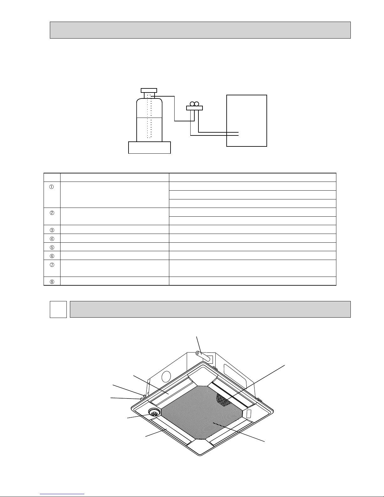
Drain pipe
Filter
Vane
Gas pipe
Liquid pipe
Air outlet
i-see sensor
(option)
Air intake
(Intake grille)
Gravimeter
Unit
[2] Additional refrigerant charge
When charging directly from cylinder
· Check that cylinder for R410A on the market is syphon type.
· Charging should be performed with the cylinder of syphon stood vertically. (Refrigerant is charged from liquid phase.)
No.
Tool name Specifications
Gauge manifold · Only for R410A
· Use the existing fitting
specifications
. (UNF1/2)
· Use high-tension side pressure of 5.3MPa·G or over.
Charge hose · Only for R410A
· Use pressure performance of 5.09MPa·G or over.
Electronic scale
—
Gas leak detector · Use the detector for R410A.
Adaptor for reverse flow check · Attach on vacuum pump.
Refrigerant charge base
—
Refrigerant cylinder · Only for R410A · Top of cylinder (Pink)
· Cylinder with syphon
Refrigerant recovery equipment
—
4-1. INDOOR UNIT
OCH412G
6
ON/OFF TEMP
FAN
VANE
TEST RUN
AUTO STOP
AUTO START
h
min
LOUVER
MODE
CHECK
RESETSET CLOCK
MODEL SELECT
NOT AV AILABLE
CHECK
TEST RUN
°C
AMPM
AMPM
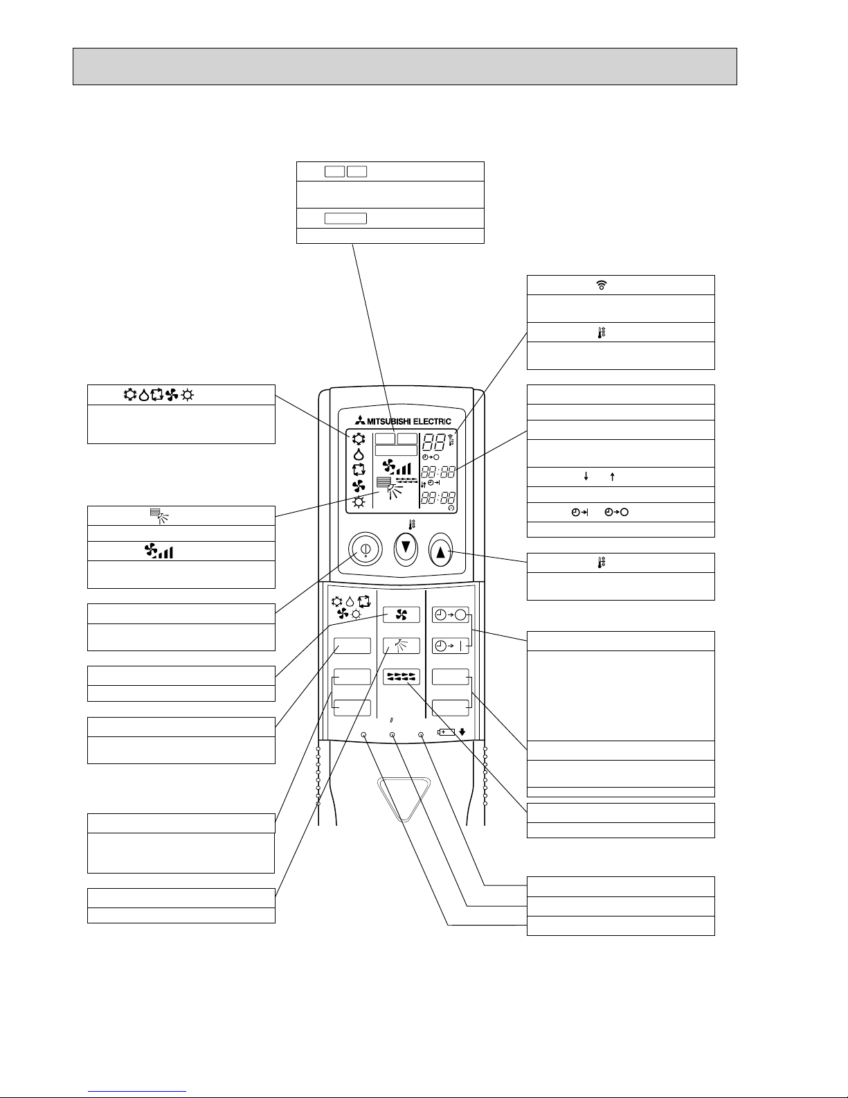
VANE CONTROL button
Used to change the air flow direction.
CLOCK button
RESET button
SET button
ON/OFF button
The unit is turned ON and OFF alternately
each time
the button is pressed.
MODE SELECT button
Used to switch the operation mode between
cooling, drying, heating, auto and fan mode.
CHECK-TEST RUN button
Only press this button to perform an
inspection check or test operation.
Do not use it for normal operation.
FAN SPEED SELECT button
Used to change the fan speed.
TIMER display
Displays when in timer operation or when
setting timer.
button
SET TEMPERATURE button sets any desired
room temperature.
CLOCK display
Displays the current time.
“ ” “ ” display
Displays the order of timer operation.
“ ” “ ” display
Displays whether timer is on or off.
Buttons used to set the “hour and minute” of
the current time and timer settings.
h and min buttons
display
display
FAN SPEED display indicates which fan
speed has been selected.
display
The vertical direction of air flow is indicated.
display
Blinks when model is selected.
display
display
CHECK and TEST RUN display indicate that
the unit is being checked or test-run.
display
OPERATION MODE display
Operation mode display indicates which
operation mode is in effect.
AUTO STOP (OFF timer): when this switch
is set, the air conditioner will be
automatically stopped at the preset time.
AUTO START (ON timer): when this switch is
set, the air conditioner will be automatically
started at the preset time.
MODEL SELECT
CHECK
TEST RUN
LOUVER button
Changes left/right airflow direction.
(Not available for this model.)
SET TEMP. display indicates the desired
temperature which is set.
Lights up while the signal is transmitted to
the indoor unit when the button is pressed.
TIMER CONTROL buttons
4-2. WIRELESS REMOTE CONTROLLER
OCH412G
7
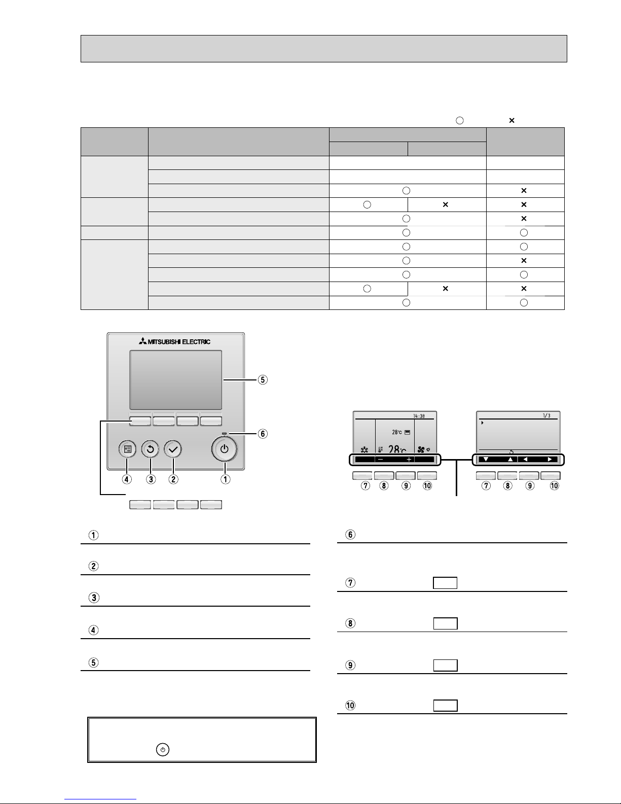
Function buttons
F1 F2 F3 F4
Press to turn ON/OFF the indoor unit.
ON / OFF button
When the backlight is off, pressing any button turns
the backlight on and does not perform its function.
(except for the
(ON / OFF) button)
The functions of the function buttons change depending on
the screen. Refer to the button function guide that appears
at the bottom of the LCD for the functions they serve on a
given screen.
When the system is centrally controlled, the button function
guide that corresponds to the locked button will not appear.
Press to save the setting.
SELECT button
Press to return to the previous screen.
RETURN button
Press to bring up the Main menu.
MENU button
Operation settings will appear.
When the backlight is off, pressing any button turns the
backlight on and it will stay lit for a certain period of time
depending on the screen.
Backlit LCD
This lamp lights up in green while the unit is in operation.
It blinks while the remote controller is starting up or when
there is an error.
ON / OFF lamp
Main display : Press to change the operation mode.
Main menu : Press to move the cursor down.
Function button
F1
Main display : Press to decrease temperature.
Main menu : Press to move the cursor up.
Function button
F2
Main display : Press to increase temperature.
Main menu : Press to go to the previous page.
Function button
F3
Main display : Press to change the fan speed.
Main menu : Press to go to the next page.
Function button
F4
Fri
Room
Set temp.
Mode Tem p. Fa n
Cool Auto
Main
Main display:
Cursor Page
Main menu
Vane·Louver·Vent. (Lossnay)
High power
Timer
Weekly timer
OU silent mode
<Main display> <Main menu>
Function guide
4-3. WIRED REMOTE CONTROLLER <PAR-30MAA/PAR-31MAA>
* The functions which can be used are restricted according to the model.
: Supported : Unsupported
Function
PAR-30MAA/PAR-31MAA
PAR-21MAA
Slim City multi
Body Product size H × W × D (mm) 120 × 120 × 19 120 × 130 × 19
LCD Full Dot LCD Partial Dot LCD
Backlight
Energy-saving Energy-saving operation schedule
Automatic return to the preset temperature
Restriction Setting the temperature range restriction
Function Operation lock function
Weekly timer
On / Off timer
High Power
Manual vane angle
Wired remote controller function
OCH412G
8
Fri
Mode Temp. Fan
Room
Cool Auto
Set temp.
Fri
Cool
Mode Temp. Fan
AutoSet temp.
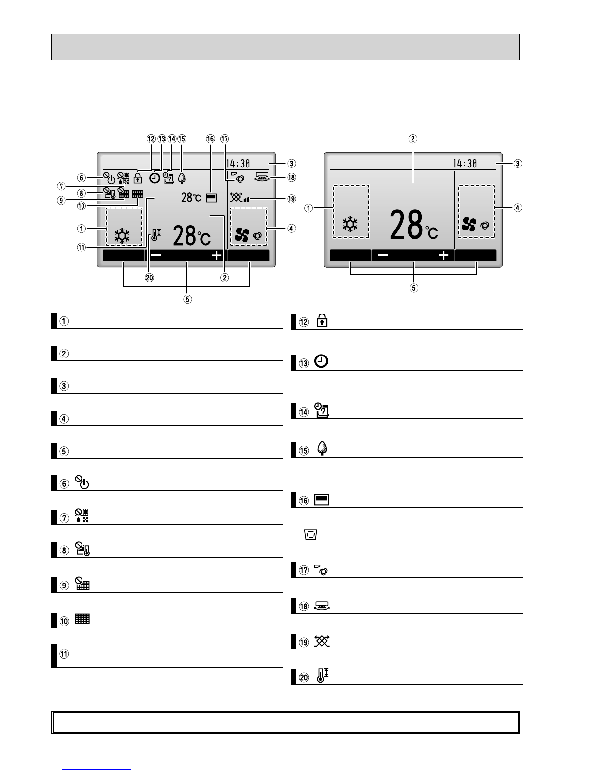
The main display can be displayed in two different modes: "Full" and "Basic".
T
he initial setting is "Full". To switch to the "Basic" mode, change the setting on the Main display setting.
<Full mode> <Basic mode>
* All icons are displayed for explanation.
Most settings (except ON / OFF, mode, fan speed, temperature) can be made from the Menu screen.
Indoor unit operation mode appears here.
Operation mode
Preset temperature appears here.
Preset temperature
Current time appears here.
Clock (See the Installation Manual.)
Fan speed
Fan speed setting appears here.
Functions of the corresponding buttons appear here.
Button function guide
Appears when the ON/OFF operation is centrally controlled.
Appears when the operation mode is centrally controlled.
Appears when the preset temperature is centrally controlled.
Appears when the fi lter reset function is centrally controlled.
Indicates when fi lter needs maintenance.
Current room temperature appears here.
Room temperature
(See the Installation Manual.)
Appears when the buttons are locked.
Appears when the On/Off timer or Night setback function is
enabled.
Appears when the Weekly timer is enabled.
Appears while the units are operated in the energy-save
mode.
Appears when the built-in thermistor on the remote controller is activated to monitor the room temperature (a).
appears when the thermistor on the indoor unit is acti-
vated to monitor the room temperature.
Indicates the vane setting.
Indicates the louver setting.
Indicates the ventilation setting.
Appears when the preset temperature range is restricted.
OCH412G
9
Not all functions are available on all models of indoor units.
Filter information
Error information
Energy saving
Auto return
Schedule
Night setback
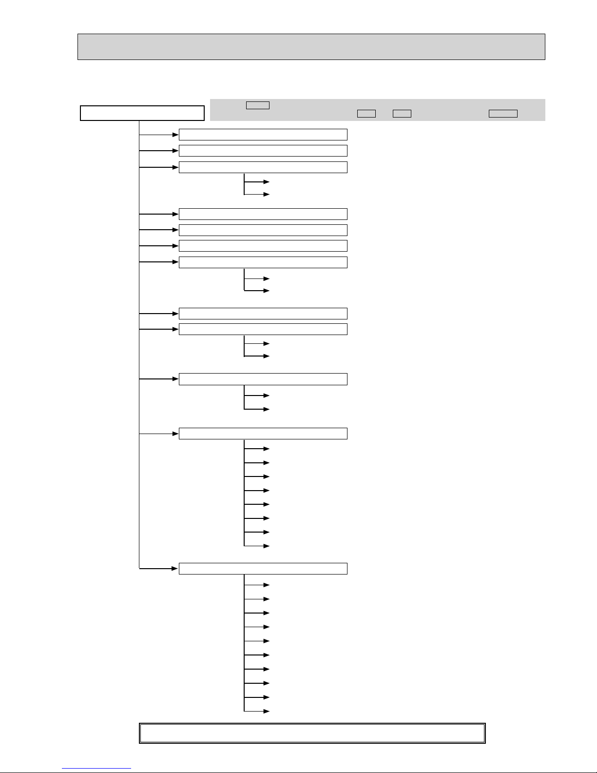
Main menu
Press the
MENU
button.
Move the cursor to the desired item with the
F1
and
F2
buttons, and press the
SELECT
button.
Vane · Louver · Vent. (Lossnay)
High power
Weekly timer
Restriction
Maintenance
Initial setting
On / Off timer
Auto-Off timer
Temp. range
Operation lock
Manual vane angle
Main / Sub
Timer
Main display
Contrast
Display details
Auto mode
Administrator password
Language selection
Service
Service menu
Input maintenance info.
Function setting
Lossnay (City Multi only)
Check
Self check
Maintenance password
Remote controller check
Test run
Clock
Drain pump test run
Auto descending panel
Menu structure
OCH412G
10
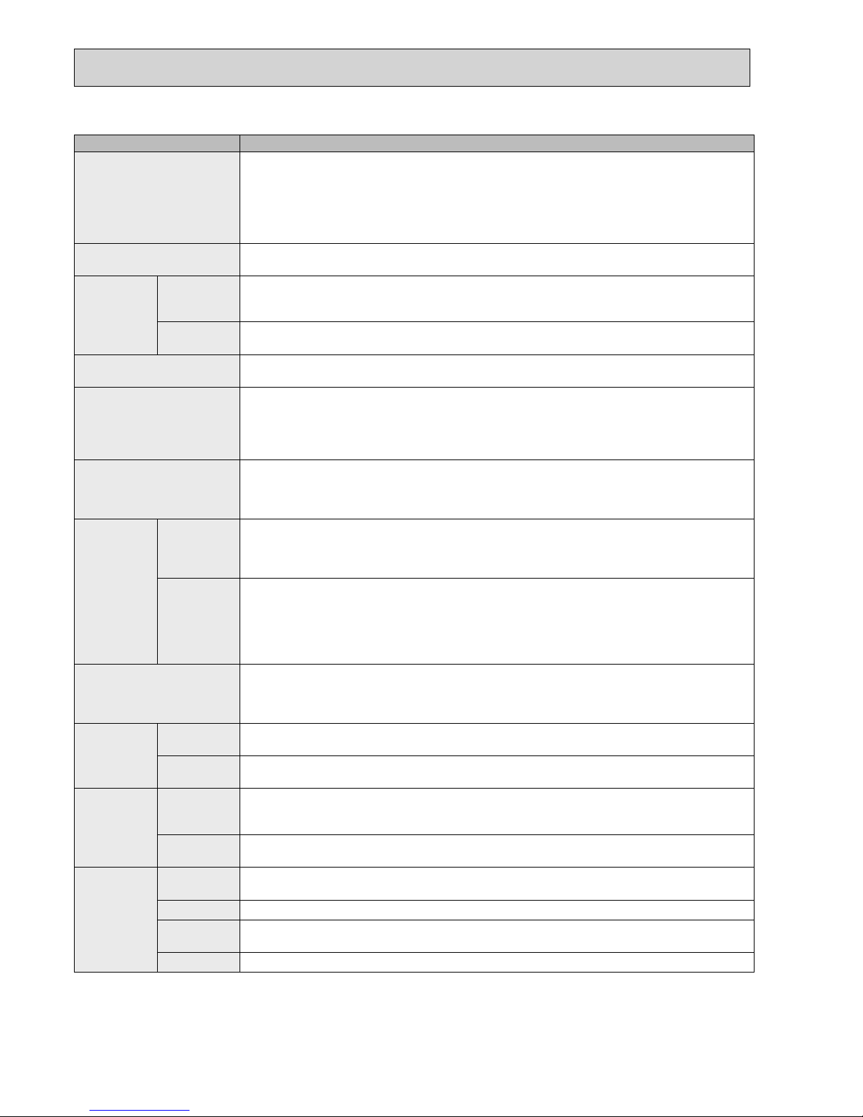
Setting and display items Setting details
Vane · Louver · Vent.
(Lossnay)
Use to set the vane angle.
• Select a desired vane setting from fi ve different settings.
Use to turn ON / OFF the louver.
• Select a desired setting from "ON" and "OFF."
Use to set the amount of ventilation.
• Select a desired setting from "Off," "Low," and "High."
High power Use to reach the comfortable room temperature quickly.
• Units can be operated in the High-power mode for up to 30 minutes.
Timer On/Off timer Use to set the operation On/Off times.
• Time can be set in 5-minute increments.
* Clock setting is required.
Auto-Off
timer
Use to set the Auto-Off time.
• Time can be set to a value from 30 to 240 in 10-minute increments.
Filter information Use to check the fi lter status.
• The fi lter sign can be reset.
Error information Use to check error information when an error occurs.
• Error code, error source, refrigerant address, unit model, manufacturing number, contact
information (dealer's phone number) can be displayed.
* The unit model, manufacturing number, and contact information need to be registered in
advance to be displayed.
Weekly timer Use to set the weekly operation On / Off times.
• Up to eight operation patterns can be set for each day.
* Clock setting is required.
* Not valid when the On/Off timer is enabled.
Energy
saving
Auto return Use to get the units to operate at the preset temperature after performing energy-save
operation for a specifi ed time period.
• Time can be set to a value from 30 and 120 in 10-minute increments.
* This function will not be valid when the preset temperature ranges are restricted.
Schedule Set the start/stop times to operate the units in the energy-save mode for each day of the
week, and set the energy-saving rate.
• Up to four energy-save operation patterns can be set for each day.
• Time can be set in 5-minute increments.
• Energy-saving rate can be set to a value from 0% or 50 to 90% in 10% increments.
* Clock setting is required.
Night setback Use to make Night setback settings.
• Select "Yes" to enable the setting, and "No" to disable the setting. The temperature range and
the start/stop times can be set.
* Clock setting is required.
Restriction Temp. range Use to restrict the preset temperature range.
• Different temperature ranges can be set for different operation modes.
Operation
lock
Use to lock selected functions.
• The locked functions cannot be operated.
Maintenance
Auto
descending
panel
Auto descending panel (Optional parts) Up / Down you can do.
Manual
vane angle
Use to set the vane angle for each vane to a fi xed position.
Initial setting
Main/Sub
When connecting two remote controllers, one of them needs to be designated as a sub
controller.
Clock
Use to set the current time.
Main display
Use to switch between "Full" and "Basic" modes for the Main display.
• The initial setting is "Full."
Contrast
Use to adjust screen contrast.
Main menu list
OCH412G
11
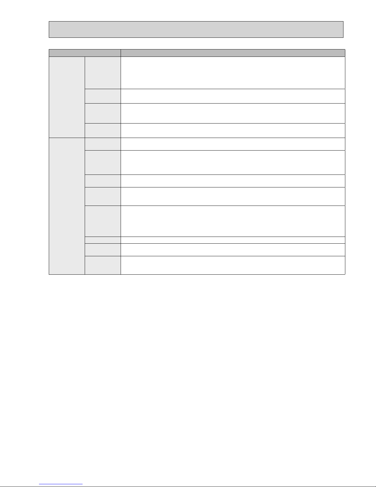
Setting and display items Setting details
Initial setting Display
details
Make the settings for the remote controller related items as necessary.
Clock: The initial settings are "Yes" and "24h" format.
Temperature: Set either Celsius (°C) or Fahrenheit (°F).
Room temp. : Set Show or Hide.
Auto mode: Set the Auto mode display or Only Auto display.
Auto mode Whether or not to use the AUTO mode can be selected by using the button.
This setting is valid only when indoor units with the AUTO mode function are connected.
Administrator
password
The administrator password is required to make the settings for the following items.
•
Timer setting • Energy-save setting • Weekly timer setting
•
Restriction setting • Outdoor unit silent mode setting • Night set back
Language
selection
Use to select the desired language.
Service
Test run Select "Test run" from the Service menu to bring up the Test run menu.
•
Test run • Drain pump test run
Input
maintenance
Select "Input maintenance Info." from the Service menu to bring up the Maintenance
information screen.
The following settings can be made from the Maintenance Information screen.
•
Model name input • Serial No. input • Dealer information input
Function
setting
Make the settings for the indoor unit functions via the remote controller as necessary.
LOSSNAY
setting
(City Multi only)
This setting is required only when the operation of City Multi units is interlocked with
LOSSNAY units.
Check Error history: Display the error history and execute delete error history.
Refrigerant leak check: Refrigerant leaks can be judged.
Smooth maintenance: The indoor and outdoor maintenance data can be displayed.
Request cord: Details of the operation data including each thermistor temperature and error
history can be checked.
Self check Error history of each unit can be checked via the remote controller.
Maintenance
password
Take the following steps to change the maintenance password.
Remote
controller
check
When the remote controller does not work properly, use the remote controller checking
function to troublushoot the problem.
OCH412G
12
°F°C
°F°C
ERROR CODE
AFTER
TIMER
TIME SUN MON TUE WED THU FRI SAT
ON
OFF
Hr
AFTER
FILTER
FUNCTION
ONLY1Hr.
WEEKLY
SIMPLE
AUTO OFF
PAR-21MAA
ON/OFF
FILTER
CHECK
OPERATION
CLEAR
TEST
TEMP.
MENU
BACK DAY
MONITOR/SET
CLOCK
ON/OFF
L
L
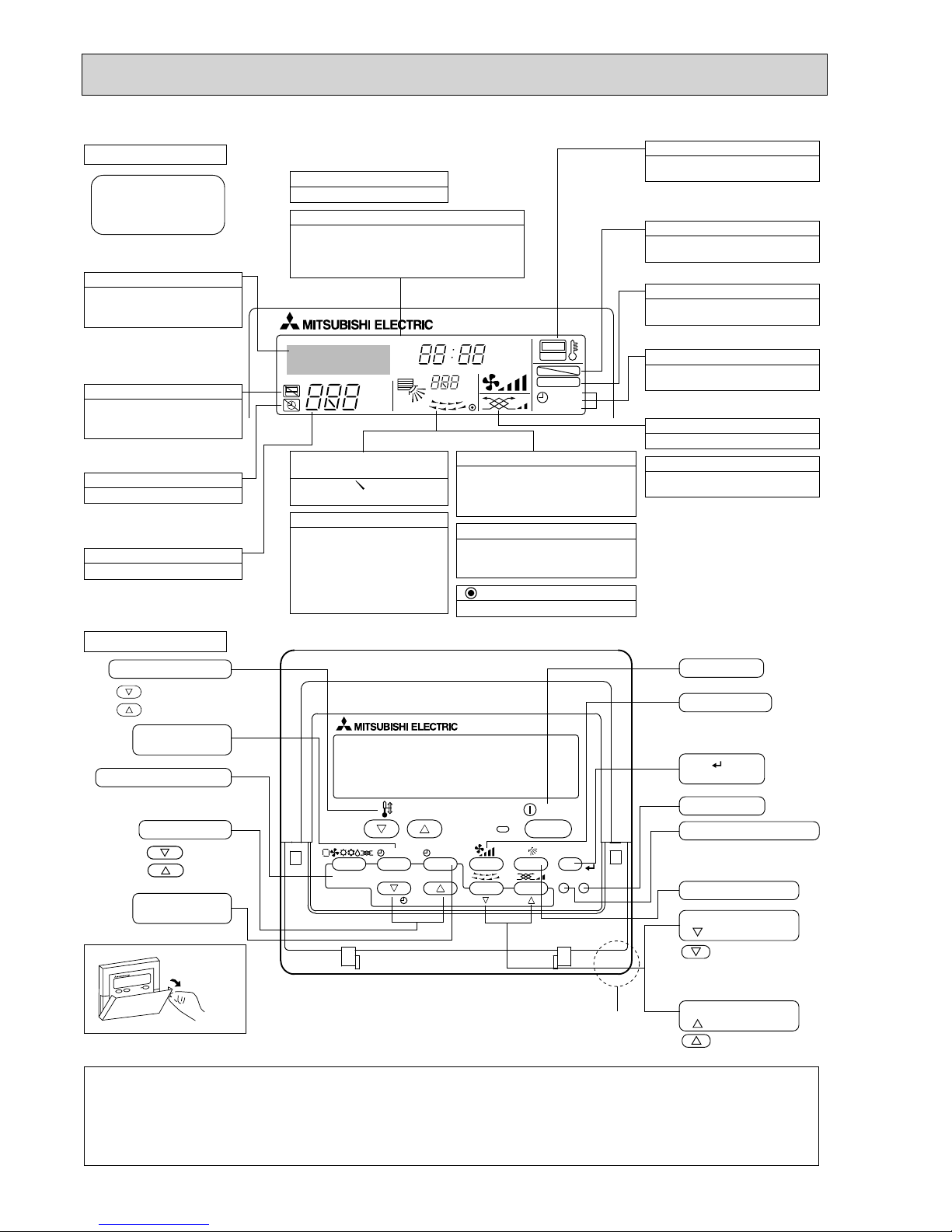
Display Section
For purposes of this explanation,
all parts of the display are shown.
During actual operation, only
the relevant items will be lit.
Identifies the current operation
Shows the operating mode, etc.
*Multilanguage display is available.
“Centrally Controlled” indicator
Indicates that operation from the
remote controller has been prohibited by a master controller.
“Timer is Off” indicator
Indicates that the timer is off.
Temperature Setting
Shows the target temperature.
Day-of-Week
Shows the current day of the week.
Time/Timer Display
Shows the current time, unless the simple or Auto Off
timer is set.
If the simple or Auto Off timer is set, the time to be
switched off is shown.
“Sensor” indication
Displayed when the remote controller
sensor is used.
“Locked” indicator
Indicates that remote controller buttons have been locked.
“Clean The Filter” indicator
To be displayed on when it is time to
clean the filter.
Timer indicators
The indicator comes on if the corresponding timer is set.
Up/Down Air Direction indicator
The indicator shows the direction of the outcoming airflow.
“One Hour Only” indicator
Room Temperature display
Shows the room temperature. The room
temperature display range is 8 – 39.
The display blinks if the temperature
is less than 8 or 39 or more.
Louver display
Indicates the action of the swing louver.
Does not appear if the louver is not
running.
(Power On indicator)
Indicates that the power is on.
Fan Speed indicator
Shows the selected fan speed.
Ventilation indicator
Appears when the unit is running in
Ventilation mode.
Operation Section
Temperature setting buttons
Down
Up
Timer Menu button
(Monitor/Set button)
Mode button (Return button)
Set Time buttons
Back
Ahead
Timer On/Off button
(Set Day button)
Opening the
cover
ON/OFF button
Fan Speed button
Filter button
(<Enter> button)
Test Run button
Check button (Clear button)
Airflow Up/Down button
Louver button
( Operation button)
T o return operation
number
Ventilation button
( Operation button)
To go to next operation
number
Note:
“PLEASE WAIT” message
This message is displayed for approximately 3 minutes when power is supplied to the indoor unit or when the unit is recovering from a power failure.
“NOT AVAILABLE” message
This message is displayed if an invalid button is pressed (to operate a function that the indoor unit does not have).
If a single remote controller is used to operate multiple indoor units simultaneously that are different types, this message will not be displayed as
far as any of the indoor units is equipped with the function.
Built-in temperature sensor
Displayed if the airflow is set to
low or downward during COOL
or DRY mode. (Operation varies
according to model.)
The indicator goes off in 1 hour,
when the airflow direction
also changes.
4-4. WIRED REMOTE CONTROLLER <PAR-21MAA>
OCH412G
13
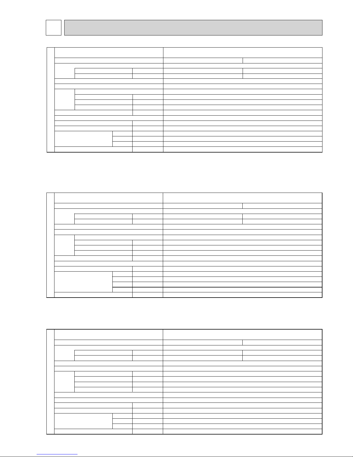
SPECIFICATIONS
5
kW
A
kW
K/min(CFM)
Pa(mmAq)
kW
dB
mm(in)
mm(in)
mm(in)
mm(in)
kg(lbs)
Mode
Power supply (phase, cycle, voltage)
Input
Running current
External finish (Panel)
Heat exchanger
Fan Fan (drive) o No.
Fan motor output
Airflow (Low-Medium2-Medium1-High)
External static pressure
Booster heater
Operation control & Thermostat
Noise level (Low-Medium2-Medium1-High)
Field drain pipe O.D.
Dimensions
Weight
W
D
H
INDOOR UNIT
Cooling
0.05
0.36
Heating
0.04
0.29
Single phase, 50Hz, 230V
Munsell 6.4Y 8.9/0.4
Plate fin coil
Turbo fan (direct) o 1
0.050
12-14-16-18(425-495-565-635)
0(direct blow)
–
Remote controller & built-in
28-29-31-32
32(1-1/4)
PLA-RP50BA.UK PLA-RP50BA
1.UK
PLA-RP50BA#2.UK PLA-RP50BAR3.UK
UNIT: 840 (33-1/16) PANEL : 950 (37-3/8)
UNIT: 840 (33-1/16) PANEL : 950 (37-3/8)
UNIT: 258 (10-3/16) PANEL : 35 (1-3/8)
UNIT: 22 (49) PANEL: 6 (13)
Service Ref.
Cooling
0.03
0.22
Heating
0.02
0.14
Single phase, 50Hz, 230V
Munsell 6.4Y 8.9/0.4
Plate fin coil
Turbo fan (direct) o 1
0.050
11-12-13-15(390-425-460-530)
0(direct blow)
–
Remote controller & built-in
27-28-29-31
32 (1-1/4)
kW
A
kW
K/min(CFM)
Pa(mmAq)
kW
dB
mm(in)
mm(in)
mm(in)
mm(in)
kg(lbs)
Mode
Power supply (phase, cycle, voltage)
Input
Running current
External finish (Panel)
Heat exchanger
Fan Fan (drive) o No.
Fan motor output
Airflow (Low-Medium2-Medium1-High)
External static pressure
Booster heater
Operation control & Thermostat
Noise level (Low-Medium2-Medium1-High)
Field drain pipe O.D.
Dimensions
Weight
W
D
H
INDOOR UNIT
PLA-RP35BA#2.UK PLA-RP35BAR3.UK
PLA-RP35BA.UK PLA-RP35BA
1.UK
UNIT: 840 (33-1/16) PANEL: 950 (37-3/8)
UNIT: 840 (33-1/16) PANEL: 950 (37-3/8)
UNIT: 258 (10-3/16) PANEL: 35 (1-3/8)
UNIT: 22 (49) PANEL: 6 (13)
Service Ref.
Cooling
0.05
0.36
Heating
0.04
0.29
Single phase, 50Hz, 230V
Munsell 6.4Y 8.9/0.4
Plate fin coil
Turbo fan (direct) o 1
0.050
12-14-16-18(425-495-565-635)
0(direct blow)
–
Remote controller & built-in
28-29-31-32
32(1-1/4)
kW
A
kW
K/min(CFM)
Pa(mmAq)
kW
dB
mm(in)
mm(in)
mm(in)
mm(in)
kg(lbs)
W
D
H
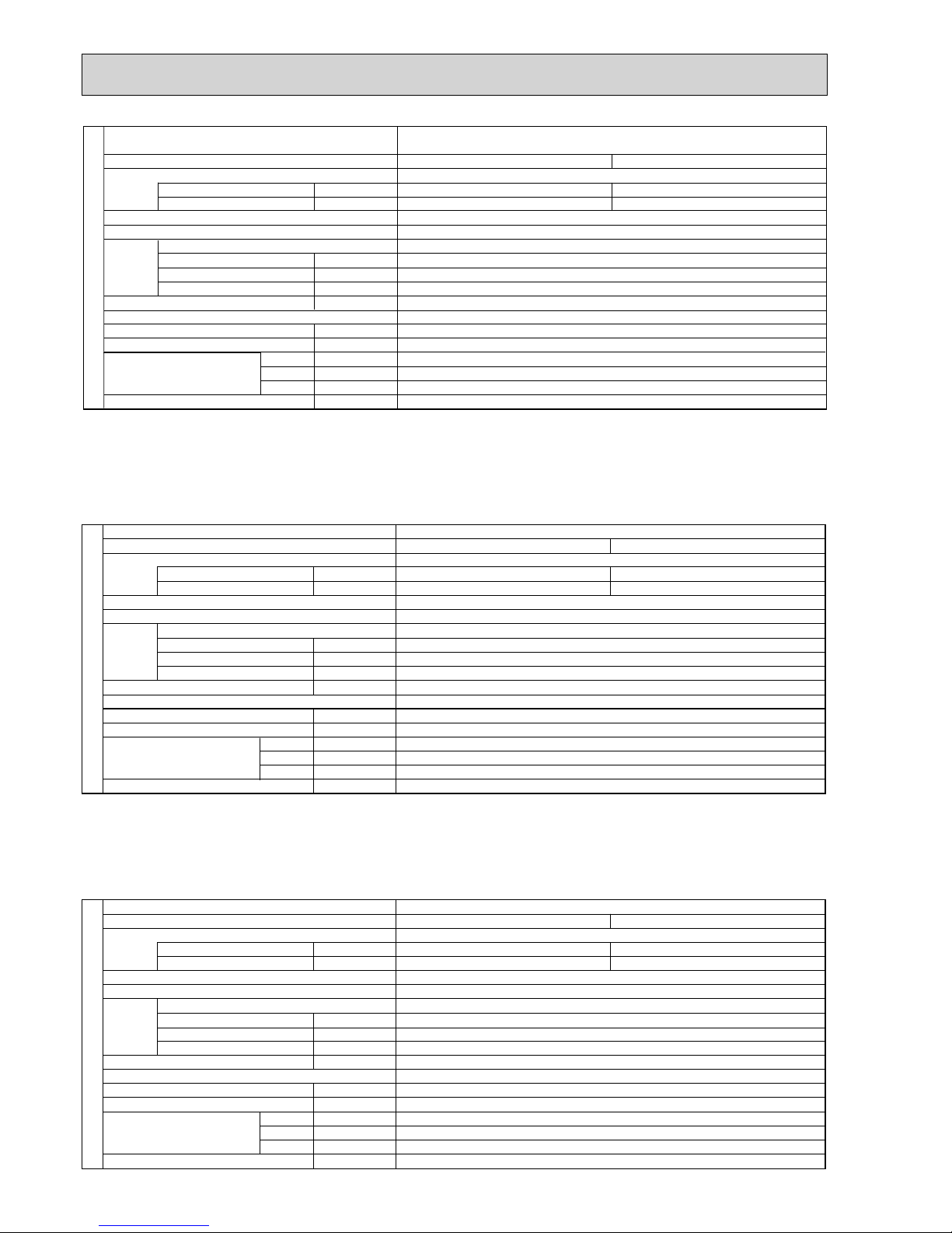
INDOOR UNIT
PLA-RP60BA.UK PLA-RP60BA1.UK
PLA-RP60BA#2.UK PLA-RP60BAR3.UK
Mode
Power supply (phase, cycle, voltage)
Input
Running current
External finish (Panel)
Heat exchanger
Fan Fan (drive) o No.
Fan motor output
Airflow (Low-Medium2-Medium1-High)
External static pressure
Booster heater
Operation control & Thermostat
Noise level (Low-Medium2-Medium1-High)
Field drain pipe O.D.
Dimensions
Weight
UNIT: 840 (33-1/16) PANEL : 950 (37-3/8)
UNIT: 840 (33-1/16) PANEL : 950 (37-3/8)
UNIT: 258 (10-3/16) PANEL : 35 (1-3/8))
UNIT: 23 (51) PANEL: 6 (13)
Service Ref.
OCH412G
14
Cooling
0.14
0.94
Heating
0.13
0.87
Single phase, 50Hz, 230V
Munsell 6.4Y 8.9/0.4
Plate n coil
Turbo fan (direct) o 1
0.120
20-23-26-30(710-810-920-1,060)
0(direct blow)
–
Remote controller & built-in
32-34-37-40
32(1-1/4)
kW
A
kW
K/min(CFM)
Pa(mmAq)
kW
dB
mm(in)
mm(in)
mm(in)
mm(in)
kg(lbs)
W
D
H
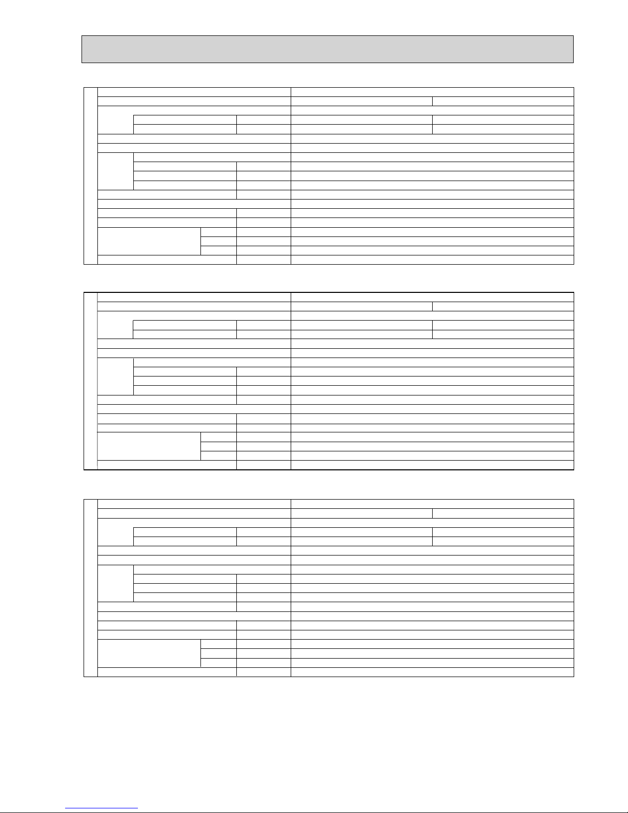
INDOOR UNIT
PLA-RP100BA.UK PLA-RP100BA#2.UK
Service Ref.
Mode
Power supply (phase, cycle, voltage)
Input
Running current
External finish (Panel)
Heat exchanger
Fan Fan (drive) o No.
Fan motor output
Airflow (Low-Medium2-Medium1-High)
External static pressure
Booster heater
Operation control & Thermostat
Noise level (Low-Medium2-Medium1-High)
Field drain pipe O.D.
Dimensions
Weight
: 840 (33-1/16) PANEL: 950 (37-3/8)
: 840 (33-1/16) PANEL: 950 (37-3/8)
: 298 (11-3/4) PANEL: 35 (1-3/8)
: 25 (55) PANEL: 6 (13)
UNIT
UNIT
UNIT
UNIT
Cooling
0.15
1.00
Heating
0.14
0.94
Single phase, 50Hz, 230V
Munsell 6.4Y 8.9/0.4
Plate fin coil
Turbo fan (direct) o 1
0.120
22-25-28-31(780-880-990-1,090)
0(direct blow)
–
Remote controller & built-in
34-36-39-41
32(1-1/4)
kW
A
kW
K/min(CFM)
Pa(mmAq)
kW
dB
mm(in)
mm(in)
mm(in)
mm(in)
kg(lbs)
W
D
H
INDOOR UNIT
PLA-RP125BA.UK PLA-RP125BA#2.UK
Service Ref.
Mode
Power supply (phase, cycle, voltage)
Input
Running current
External finish (Panel)
Heat exchanger
Fan Fan (drive) o No.
Fan motor output
Airflow (Low-Medium2-Medium1-High)
External static pressure
Booster heater
Operation control & Thermostat
Noise level (Low-Medium2-Medium1-High)
Field drain pipe O.D.
Dimensions
Weight
: 840 (33-1/16) PANEL: 950 (37-3/8)
: 840 (33-1/16) PANEL: 950 (37-3/8)
: 298 (11-3/4) PANEL: 35 (1-3/8)
: 25 (55) PANEL: 6 (13)UNIT
UNIT
UNIT
UNIT
Cooling
0.07
0.51
Heating
0.06
0.43
Single phase, 50Hz, 230V
Munsell 6.4Y 8.9/0.4
Plate fin coil
Turbo fan (direct) o 1
0.050
14-16-18-21(485-565-635-740)
0(direct blow)
–
Remote controller & built-in
28-30-32-34
32(1-1/4)
kW
A
kW
K/min(CFM)
Pa(mmAq)
kW
dB
mm(in)
mm(in)
mm(in)
mm(in)
kg(lbs)
Mode
Power supply (phase, cycle, voltage)
Input
Running current
External finish (Panel)
Heat exchanger
Fan Fan (drive) o No.
Fan motor output
Airflow (Low-Medium2-Medium1-High)
External static pressure
Booster heater
Operation control & Thermostat
Noise level (Low-Medium2-Medium1-High)
Field drain pipe O.D.
Dimensions
Weight
W
D
H
INDOOR UNIT
PLA-RP71BA.UK PLA-RP71BA1.UK
PLA-RP71BA#2.UK PLA-RP71BAR3.UK
UNIT : 840 (33-1/16) PANEL : 950 (37-3/8)
UNIT : 840 (33-1/16) PANEL : 950 (37-3/8)
UNIT : 258 (10-3/16) PANEL : 35 (1-3/8)
UNIT : 23 (51) PANEL: 6 (13)
Service Ref.
OCH412G
15
kW
A
kW
K/min(CFM)
Pa(mmAq)
kW
dB
mm(in)
mm(in)
mm(in)
mm(in)
kg(lbs)
Service Ref.
Mode
Power supply (phase, cycle, voltage)
Input
Running current
External finish (Panel)
Heat exchanger
Fan Fan(drive) o No.
Fan motor output
Airflow (Low-Medium2-Medium1-High)
External static pressure
Booster heater
Operation control & Thermostat
Noise level (Low-Medium2-Medium1-High)
Field drain pipe O.D.
Dimensions
Weight
W
D
H
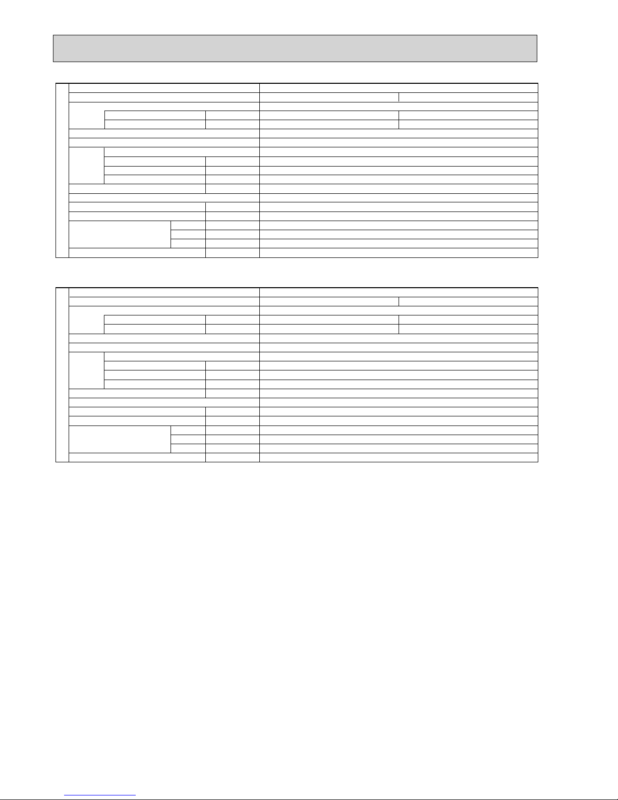
INDOOR UNIT
PLA-RP140BA.UK PLA-RP140BA#2.UK
Cooling
0.16
1.07
Heating
0.15
1.00
Single phase, 50Hz, 230V
Munsell 6.4Y 8.9/0.4
Plate fin coil
Turbo fan (direct) o 1
0.120
24-26-29-32(850-920-1,020-1,130)
0(direct blow)
–
Remote controller & built-in
36-39-42-44
32(1-1/4)
: 840 (33-1/16) PANEL: 950 (37-3/8)
: 840 (33-1/16) PANEL: 950 (37-3/8)
: 298 (11-3/4) PANEL: 35 (1-3/8)
: 27 (60) PANEL: 6 (13)UNIT
UNIT
UNIT
UNIT
Cooling
0.07
0.51
Heating
0.06
0.43
Single phase, 50Hz, 230V
Munsell 6.4Y 8.9/0.4
Plate fin coil
Turbo fan (direct) o 1
0.050
14-16-18-21(485-565-635-740)
0(direct blow)
–
Remote controller & built-in
28-30-32-34
32(1-1/4)
kW
A
kW
K/min(CFM)
Pa(mmAq)
kW
dB
mm(in)
mm(in)
mm(in)
mm(in)
kg(lbs)
Service Ref.
Mode
Power supply (phase, cycle, voltage)
Input
Running current
External finish (Panel)
Heat exchanger
Fan Fan (drive) o No.
Fan motor output
Airflow (Low-Medium2-Medium1-High)
External static pressure
Booster heater
Operation control & Thermostat
Noise level (Low-Medium2-Medium1-High)
Field drain pipe O.D.
Dimensions
Weight
W
D
H
INDOOR UNIT
PLA-RP71BA2.UK
UNIT
: 840 (33-1/16) PANEL : 950 (37-3/8)
UNIT : 840 (33-1/16) PANEL : 950 (37-3/8)
UNIT : 258 (10-3/16) PANEL : 35 (1-3/8)
UNIT : 23 (51) PANEL: 6 (13)
UNIT
UNIT
Cooling
0.15
1.00
Heating
0.14
0.94
Single phase, 50Hz, 230V
Munsell 6.4Y 8.9/0.4
Plate fin coil
Turbo fan (direct) o 1
0.120
20-23-26-30(710-810-920-1,060)
0(direct blow)
–
Remote controller & built-in
32-34-37-40
32(1-1/4)
kW
A
kW
K/min(CFM)
Pa(mmAq)
kW
dB
mm(in)
mm(in)
mm(in)
mm(in)
kg(lbs)
W
D
H
INDOOR UNIT
PLA-RP100BA2.UK
Service Ref.
Mode
Power supply (phase, cycle, voltage)
Input
Running current
External finish (Panel)
Heat exchanger
Fan Fan (drive) o No.
Fan motor output
Airflow (Low-Medium2-Medium1-High)
External static pressure
Booster heater
Operation control & Thermostat
Noise level (Low-Medium2-Medium1-High)
Field drain pipe O.D.
Dimensions
Weight
: 840 (33-1/16) PANEL: 950 (37-3/8)
: 840 (33-1/16) PANEL: 950 (37-3/8)
: 298 (11-3/4) PANEL: 35 (1-3/8)
: 27(60) PANEL: 6 (13)UNIT
UNIT
OCH412G
16
Cooling
0.16
1.07
Heating
0.15
1.00
Single phase, 50Hz, 230V
Munsell 6.4Y 8.9/0.4
Plate fin coil
Turbo fan (direct) o 1
0.120
22-25-28-31(780-880-990-1,090)
0(direct blow)
–
Remote controller & built-in
34-36-39-41
32(1-1/4)
kW
A
kW
K/min(CFM)
Pa(mmAq)
kW
dB
mm(in)
mm(in)
mm(in)
mm(in)
kg(lbs)
W
D
H
INDOOR UNIT
PLA-RP125BA2.UK
Service Ref.
Mode
Power supply (phase, cycle, voltage)
Input
Running current
External finish (Panel)
Heat exchanger
Fan Fan (drive) o No.
Fan motor output
Airflow (Low-Medium2-Medium1-High)
External static pressure
Booster heater
Operation control & Thermostat
Noise level (Low-Medium2-Medium1-High)
Field drain pipe O.D.
Dimensions
Weight
: 840 (33-1/16) PANEL: 950 (37-3/8)
: 298 (11-3/4) PANEL: 35 (1-3/8)
: 27(60) PANEL: 6 (13)UNIT
UNIT
UNIT
: 840 (33-1/16) PANEL: 950 (37-3/8)UNIT
kW
A
kW
K/min(CFM)
Pa(mmAq)
kW
dB
mm(in)
mm(in)
mm(in)
mm(in)
kg(lbs)
Service Ref.
Mode
Power supply (phase, cycle, voltage)
Input
Running current
External finish (Panel)
Heat exchanger
Fan Fan(drive) o No.
Fan motor output
Airflow (Low-Medium2-Medium1-High)
External static pressure
Booster heater
Operation control & Thermostat
Noise level (Low-Medium2-Medium1-High)
Field drain pipe O.D.
Dimensions
Weight
W
D
H
INDOOR UNIT
PLA-RP140BA2.UK
Cooling
0.16
1.07
Heating
0.15
1.00
Single phase, 50Hz, 230V
Munsell 6.4Y 8.9/0.4
Plate fin coil
Turbo fan (direct) o 1
0.120
24-26-29-32(850-920-1,020-1,130)
0(direct blow)
–
Remote controller & built-in
36-39-42-44
32(1-1/4)
: 840 (33-1/16) PANEL: 950 (37-3/8)
: 840 (33-1/16) PANEL: 950 (37-3/8)
: 298 (11-3/4) PANEL: 35 (1-3/8)
: 27 (60) PANEL: 6 (13)UNIT
UNIT
UNIT
UNIT
OCH412G
 Loading...