

Mitsubishi PLA-RP100BA3 Service Manual
SPLIT-TYPE, HEAT PUMP AIR CONDITIONERS
SPLIT-TYPE, AIR CONDITIONERS
SERVICE MANUAL
April 2009
No. OCH459
Indoor unit
[Model names] [Service Ref.]
PLA-RP100BA3
PLA-RP100BA3
NOTE:
• This manual describes
only service data of the
indoor units.
• RoHS compliant products have <G> mark on
the spec name plate.
CONTENTS
Model name
indication
INDOOR UNIT
ON/OFF TEMP
WIRELESS REMOTE
CONTROLLER
TEMP.
WIRED REMOTE
CONTROLLER
ON/OFF
1. REFERENCE MANUAL
2. SAFETY PRECAUTION
3. PART NAMES AND FUNCTIONS
4. SPECIFICATIONS
5. NOISE CRITERION CURVES
6. OUTLINES AND DIMENSIONS
7. WIRING DIAGRAM
8. REFRIGERANT SYSTEM DIAGRAM
9. TROUBLESHOOTING
10. SPECIAL FUNCTION
11. DISASSEMBLY PROCEDURE
...................................
...................................
...................
............................................
..........................
.......................
.........................................
....................................
.....................................
.......................
PARTS CATALOG (OCB459)
............
2
3
4
7
8
9
10
11
12
27
36
1
REFERENCE MANUAL
OUTDOOR UNIT’S SERVICE MANUAL
Service Ref. Service Manual No.
PU(H)-P100VHA#2.UK
PU(H)-P100YHA#2.UK
PUHZ-P100VHA3.UK OCH415/OCB415
PUHZ-P200YHA3 OCH424/OCB424
PUHZ-HRP100VHA2
PUHZ-HRP100YHA2
PUHZ-RP100VKA
PUHZ-RP100/200YKA
OC379
OCH425/OCB425
OCH451/OCB451
2
2
SAFETY PRECAUTION
2-1. ALWAYS OBSERVE FOR SAFETY
Before obtaining access to terminal, all supply
circuits must be disconnected.
2-2. CAUTIONS RELATED TO NEW REFRIGERANT
Cautions for units utilising refrigerant R410A
Use new refrigerant pipes.
In case of using the existing pipes for R22, be careful with
the followings.
· For RP100, 125 and 140, be sure to perform replace ment operation before test run.
· Change flare nut to the one provided with this product.
Use a newly flared pipe.
· Avoid using thin pipes.
Make sure that the inside and outside of refrigerant piping is clean and it has no contamination
such as sulfur hazardous for use, oxides, dirt,
shaving particles, etc.
In addition, use pipes with specified thickness.
Contamination inside refrigerant piping can cause deterioration of refrigerant oil etc.
Store the piping to be used indoors during
installation, and both ends of the piping sealed
until just before brazing. (Leave elbow joints, etc.
in their packaging.)
If dirt, dust or moisture enters into refrigerant cycle, that can
cause deterioration of refrigerant oil or malfunction of compressor.
Do not use refrigerant other than R410A.
If other refrigerant (R22 etc.) is used, chlorine in refrigerant can cause deterioration of refrigerant oil etc.
Use a vacuum pump with a reverse flow check
valve.
Vacuum pump oil may flow back into refrigerant cycle and
that can cause deterioration of refrigerant oil etc.
Use the following tools specifically designed for
use with R410A refrigerant.
The following tools are necessary to use R410A refrigerant.
Tools for R410A
Gauge manifold
Charge hose
Gas leak detector
Torque wrench
Flare tool
Size adjustment gauge
Vacuum pump adaptor
Electronic refrigerant
charging scale
Handle tools with care.
If dirt, dust or moisture enters into refrigerant cycle, that can
cause deterioration of refrigerant oil or malfunction of compressor.
Use ester oil, ether oil or alkylbenzene oil (small
amount) as the refrigerant oil applied to flares
and flange connections.
If large amount of mineral oil enters, that can cause deterioration of refrigerant oil etc.
Do not use a charging cylinder.
If a charging cylinder is used, the composition of refrigerant will change and the efficiency will be lowered.
Ventilate the room if refrigerant leaks during
Charge refrigerant from liquid phase of gas
cylinder.
If the refrigerant is charged from gas phase, composition
change may occur in refrigerant and the efficiency will be
lowered.
operation. If refrigerant comes into contact with
a flame, poisonous gases will be released.
[1] Cautions for service
(1) Perform service after recovering the refrigerant left in unit completely.
(2) Do not release refrigerant in the air.
(3) After completing service, charge the cycle with specified amount of refrigerant.
(4) When performing service, install a filter drier simultaneously.
Be sure to use a filter drier for new refrigerant.
[2] Additional refrigerant charge
When charging directly from cylinder
· Check that cylinder for R410A on the market is syphon type.
· Charging should be performed with the cylinder of syphon stood vertically. (Refrigerant is charged from liquid phase.)
3
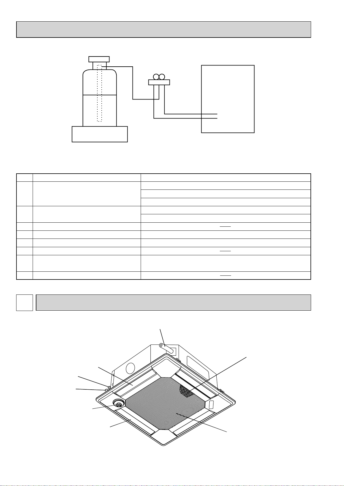
Unit
Gravimeter
[3] Service tools
Use the below service tools as exclusive tools for R410A refrigerant.
No. Tool name Specifications
1 Gauge manifold · Only for R410A
· Use the existing fitting
· Use high-tension side pressure of 5.3MPa·G or over.
2 Charge hose · Only for R410A
· Use pressure performance of 5.09MPa·G or over.
3 Electronic scale
4 Gas leak detector · Use the detector for R134a, R407C or R410A.
5 Adaptor for reverse flow check · Attach on vacuum pump.
6 Refrigerant charge base
7 Refrigerant cylinder · Only for R410A · Top of cylinder (Pink)
· Cylinder with syphon
8 Refrigerant recovery equipment
specifications
. (UNF1/2)
3
Liquid pipe
PART NAMES AND FUNCTIONS
Drain pipe
Filter
Air outlet
Gas pipe
i-see sensor
(option)
Vane
Air intake
(Intake grille)
4
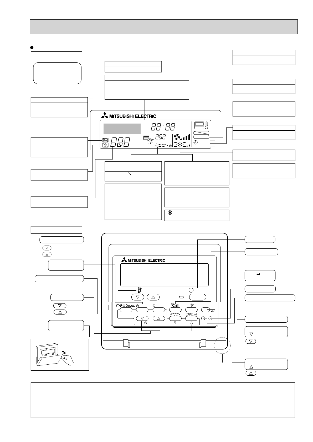
Wired remote controller
Display Section
For purposes of this explanation,
all parts of the display are shown
as lit. During actual operation, only
the relevant items will be lit.
Identifies the current operation
Shows the operating mode, etc.
*Multilanguage display is available.
“Centrally Controlled” indicator
Indicates that operation from the
remote controller has been prohibited by a master controller.
“Timer is Off” indicator
Indicates that the timer is off.
Temperature Setting
Shows the target temperature.
Day-of-Week
Shows the current day of the week.
Time/Timer Display
Shows the current time, unless the simple or Auto Off
timer is set.
If the simple or Auto Off timer is set, the time to be
switched off is shown.
TIME SUN MON TUE WED THU FRI SAT
TIMER
AFTER
ERROR CODE
°F°C
Hr
AFTER
°F°C
ONLY1Hr.
Up/Down Air Direction indicator
The indicator shows the direction of the outcoming airflow.
“One Hour Only” indicator
Displayed if the airflow is set to
low or downward during COOL
or DRY mode. (Operation varies
according to model.)
The indicator goes off in 1 hour,
when the airflow direction
also changes.
Room Temperature display
Shows the room temperature. The room
temperature display range is 8–39.
The display blinks if the temperature
is less than 8 or 39 or more.
Louver display
Indicates the action of the swing louver.
Does not appear if the louver is not
running.
(Power On indicator)
Indicates that the power is on.
ON
OFF
FUNCTION
FILTER
WEEKLY
SIMPLE
AUTO OFF
“Sensor” indication
Displayed when the remote controller
sensor is used.
“Locked” indicator
Indicates that remote controller buttons have been locked.
“Clean The Filter” indicator
To be displayed on when it is time to
clean the filter.
Timer indicators
The indicator comes on if the corresponding timer is set.
Fan Speed indicator
Shows the selected fan speed.
Ventilation indicator
Appears when the unit is running in
Ventilation mode.
Operation Section
Temperature setting buttons
Down
Up
Timer Menu button
(Monitor/Set button)
Mode button (Return button)
Set Time buttons
Back
Ahead
Timer On/Off button
(Set Day button)
Opening the
lid
Note:
L
“PLEASE WAIT” message
TEMP.
MENU
BACK DAY
MONITOR/SET
PAR-21MAA
CLOCK
ON/OFF
OPERATION
ON/OFF
FILTER
CHECK
TEST
CLEAR
Built-in temperature sensor
This message is displayed for approximately 3 minutes when power is supplied to the indoor unit or when the unit is recovering from a power failure.
L
“NOT AVAILABLE” message
This message is displayed if an invalid button is pressed (to operate a function that the indoor unit does not have).
If a single remote controller is used to operate multiple indoor units simultaneously that are different types, this message will not be displayed as
far as any of the indoor units is equipped with the function.
ON/OFF button
Fan Speed button
Filter button
(<Enter> button)
Test Run button
Check button (Clear button)
Airflow Up/Down button
Louver button
( Operation button)
To return operation
number
Ventilation button
( Operation button)
To go to next operation
number
5
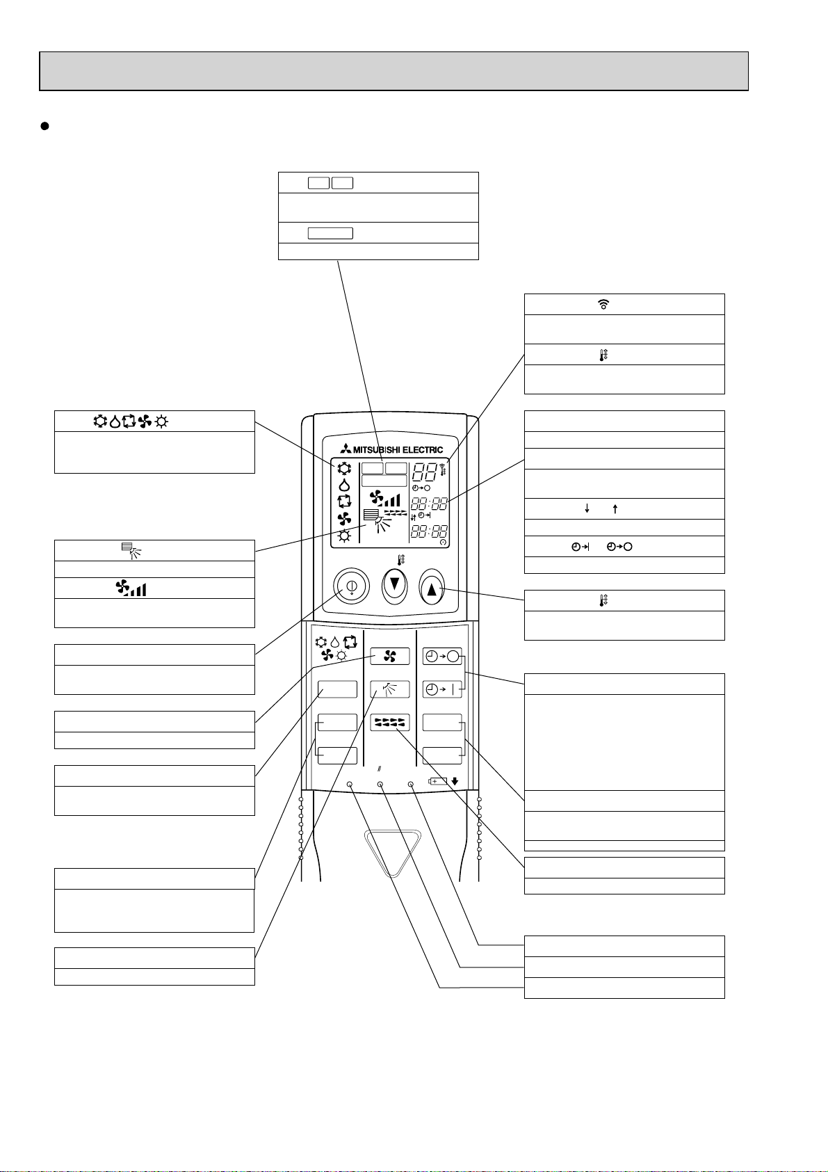
Wireless remote controller
CHECK
TEST RUN
display
CHECK and TEST RUN display indicate that
the unit is being checked or test-run.
MODEL SELECT
Blinks when model is selected.
display
display
Lights up while the signal is transmitted to
the indoor unit when the button is pressed.
display
SET TEMP. display indicates the desired
temperature which is set.
display
OPERATION MODE display
Operation mode display indicates which
operation mode is in effect.
display
The vertical direction of air flow is indicated.
display
FAN SPEED display indicates which fan
speed has been selected.
ON/OFF button
The unit is turned ON and OFF alternately
each time the button is pressed.
FAN SPEED SELECT button
Used to change the fan speed.
MODE SELECT button
Used to switch the operation mode between
cooling, drying, heating, auto and fan mode.
CHECK
TEST RUN
MODEL SELECT
NOT AVAILABLE
ON/OFF TEMP
FAN
MODE
CHECK
VAN E
LOUVER
TEST RUN
RESETSET CLOCK
°C
AMPM
AMPM
AUTO STOP
AUTO START
h
min
CLOCK display
Displays the current time.
TIMER display
Displays when in timer operation or when
setting timer.
“ ” “ ” display
Displays the order of timer operation.
“ ” “ ” display
Displays whether timer is on or off.
button
SET TEMPERATURE button sets any desired
room temperature.
TIMER CONTROL buttons
AUTO STOP (OFF timer): when this switch
is set, the air conditioner will be
automatically stopped at the preset time.
AUTO START (ON timer): when this switch is
set, the air conditioner will be automatically
started at the preset time.
h and min buttons
Buttons used to set the “hour and minute” of
the current time and timer settings.
CHECK-TEST RUN button
Only press this button to perform an
inspection check or test operation.
Do not use it for normal operation.
VANE CONTROL button
Used to change the air flow direction.
LOUVER button
Changes left/right airflow direction.
(Not available for this model.)
CLOCK button
RESET button
SET button
6
4
SPECIFICATIONS
Service Ref.
Mode
Power supply (phase, cycle, voltage)
Input
Running current
External finish (Panel)
Heat exchanger
Fan Fan (drive) % No.
Fan motor output
External static pressure
Booster heater
INDOOR UNIT
Operation control & Thermostat
Noise level (Low-Medium2-Medium1-High)
Field drain pipe O.D.
Dimensions
Weight
Airflow (Low-Medium2-Medium1-High)
*/min(CFM)
Pa(mmAq)
W
D
H
kW
A
kW
kW
dB
mm(in.)
mm(in.)
mm(in.)
mm(in.)
kg(lbs)
Cooling
PLA-RP100BA3
Single phase, 50Hz, 230V
0.15
1.00
Munsell 6.4Y 8.9/0.4
Plate fin coil
Turbo fan (direct) % 1
0.120
20-23-26-30(710-810-920-1,060)
0(direct blow)
–
Remote controller & built-in
32-34-37-40
32(1-1/4)
UNIT : 840 (33-1/16) PANEL : 950 (37-3/8)
UNIT : 840 (33-1/16) PANEL : 950 (37-3/8)
UNIT : 298 (11-3/4) PANEL : 35 (1-3/8)
UNIT : 26 (57) PANEL : 6 (13)
Heating
0.14
0.94
7
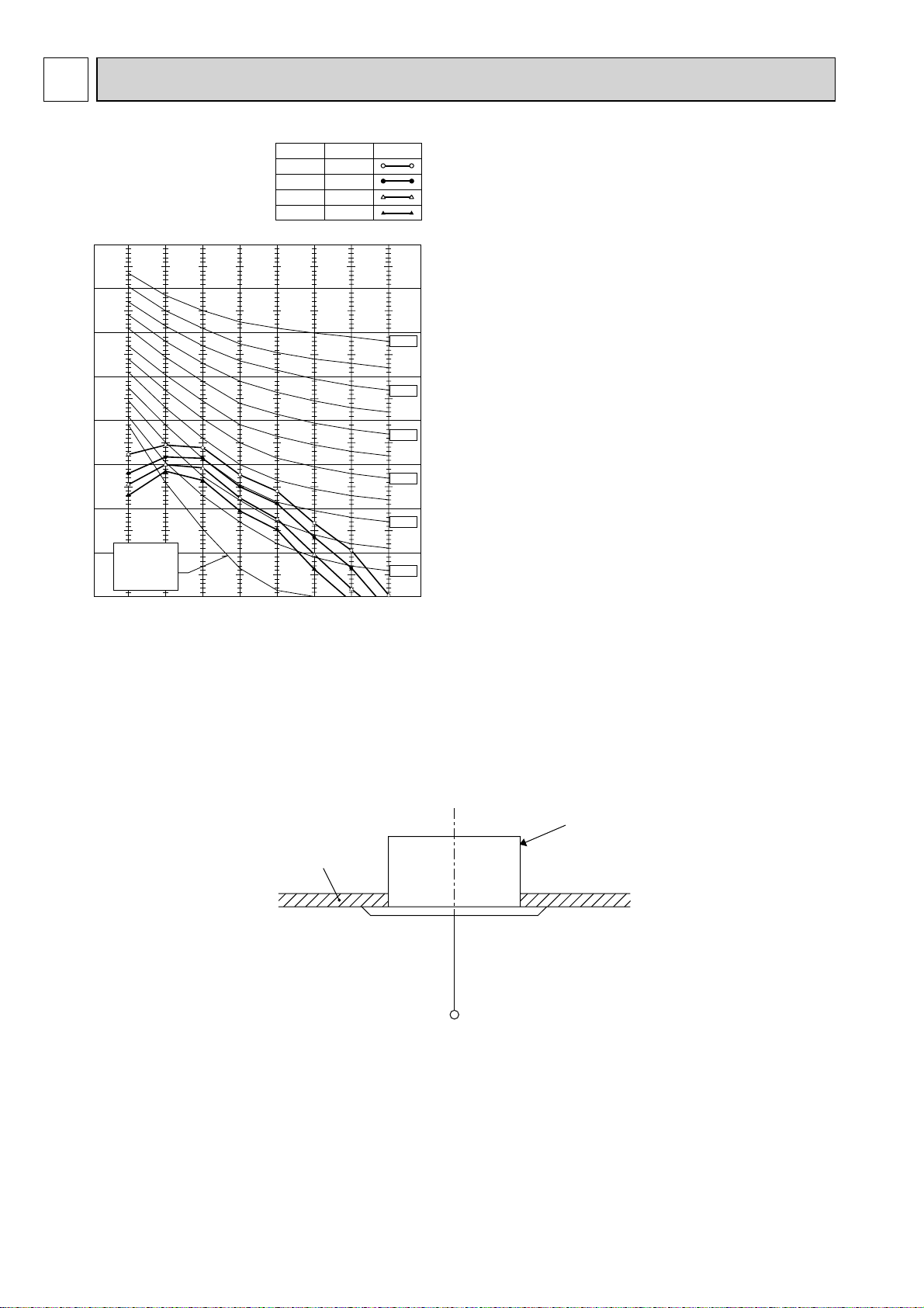
5
NOISE CRITERION CURVES
PLA-RP100BA3
90
80
70
60
50
40
30
APPROXIMATE
20
OCTAVE BAND SOUND PRESSURE LEVEL, dB (0 dB = 0.0002 μbar)
THRESHOLD OF
HEARING FOR
CONTINUOUS
NOISE
10
63 125 250 500 1000 2000 4000 8000
BAND CENTER FREQUENCIES, Hz
NOTCH SPL(dB) LINE
High 40
Medium1 37
Medium2 34
Low 32
NC-70
NC-60
NC-50
NC-40
NC-30
NC-20
CEILING
UNIT
1.5m
MICROPHONE
8
6
37728460
()
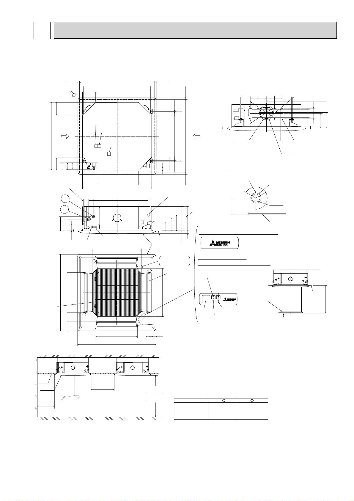
Ceiling hole
Branch duct hole
Drain pipe
connected to VP-25
Ceiling
Grille
Drain hole
Models
Auto vane
(Air outlet)
Air intake grille
Ceiling
Cut out hole
Cut out hole
Cut out hole
Burring hole pitch
Burring hole pitch
Burring hole
Burring hole
Power supply wire,
Indoor unit/Outdoor unit
connecting wire entry
Indoor unit/Outdoor unit
connecting terminal block
Indoor power supply
terminal block(Option part)
Control wire entry
Air intake hole
Air intake hole
Air outlet hole
Air outlet hole
Connected the attached
flexible pipe or socket.
Keep approximately
10 to 15mm space
between unit ceiling
and ceiling slab.
Branch duct hole
Fresh air
intake hole
Ceiling hole
Suspension bolt pitch
Suspension bolt pitch
Remote controller
terminal block
Suspension bolt
M10 or W3/8
(7.5)(7.5)
605
+35
- 5
620
DEFROST/STAND BY lamp
Receiver
Operation lamp
In case of standard grille : PLP-6BA / PLP-6BAMD
In case of wireless remote controller : PLP-6BALM Auto grille
Air intake grille up/down distance
Emergency operation
switch<Cooling>and
Emergency Up/Down switch<Up>
160
160
500
500
597
83 36
950
8336
950
597
281
17
+5
0
28835
190
156
105
140
50~70
160
840
150
90
85
77
840
187.5
20~45
860~910
20~45
810
20~45
860~910
20~45
24
160
++
+
+
+
+
+
+
+
M
M
M
M
120°
120°
:175
:125
167
158
Vane motor
2
1
Drain pump clean hole
and Drain emergency
drainage hole
130
100
70°
155
350
90 100
100 90
2
1
Refrigerant pipe
···:9.52
Flared connection
···3/8 inch
Refrigerant pipe
···:15.88
Flared connection
···5/8 inch
PLA-RP100BA3
Detail drawing of fresh air intake hole
Detail connecting of branch duct(Both aspects)
3-:2.8
14-:2.8
:150
:100
Emergency operation
switch<Heating>and
Emergency Up/Down switch<Down>
In case of auto-grille : PLP-6BAJ
Suspension bolt
lower edge
170
+
Ceiling
Air intake grille
Max. 4.0m
L.L Filter
Ceiling
Grille
Indoor unit
1500mm
or more
1000mm
or more
3000mm or more
1800mm or more
from floor
For high
attachment
Indoor unit
Obstacle
Floor
Note1. Please choose the grille from a standard grille, auto-grille.
2. As for drain pipe, please use VP-25(O.D.
:
32 PVC TUBE).
Drain pump is included.
Max. lifting height is 850mm from the ceiling.
3. As for suspension bolt, please use M10 or W3/8.
(Procured at local site)
4. Electrical box may be removed for the service purpose.
Make sure to slack the electrical wire little bit for control/power wires connection.
5. The height of the indoor unit can be adjusted with the grille attached.
6. For the installation of the optional high efficiency filter or optional multi-functional casement.
1) Requires 440 mm or more space between transom and ceiling for the installation.
2) Add 135 mm to the dimensions + marked on the figure.
3) Optional high efficiency filter must be used jointly with optional multi-functional casement .
7. When installing the branch ducts, be sure to insulate adequately.
Otherwise condensation and dripping may occur.
(It becomes the cause of dew drops/Water dew.)
8. As for necessary installation/service space, please refer to the left figure.
OUTLINES AND DIMENSIONS
PLA-RP100BA3
Unit: mm
9
7
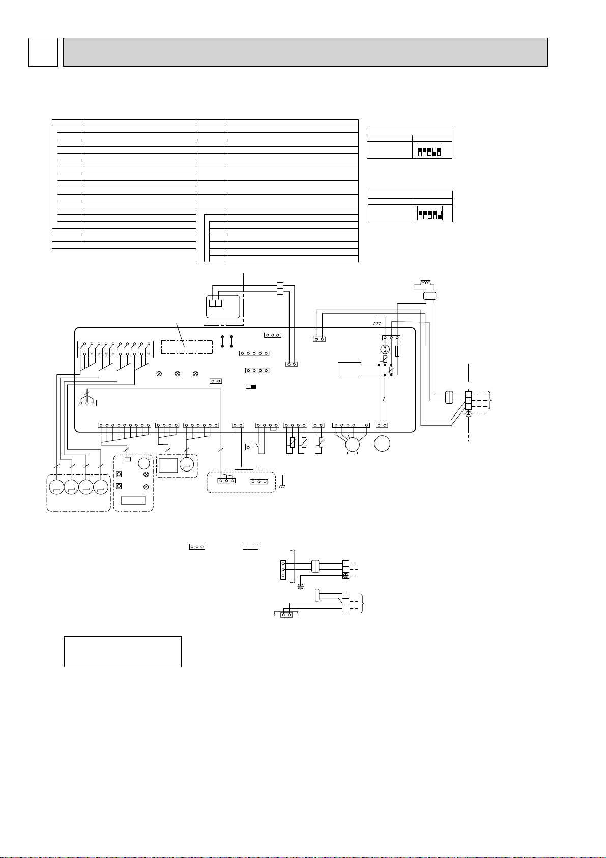
WIRING DIAGRAM
PLA-RP100BA3
[LEGEND]
SYMBOL SYMBOLNAME NAME
I.B
DCL
DP
FS
MMMM
INDOOR CONTROLLER BOARD
CN2L
CONNECTOR (LOSSNAY)
CN32
CONNECTOR (REMOTE SWITCH)
CONNECTOR (HA TERMINAL-A)
CN41
CN51
CONNECTOR (CENTRALLY CONTROL)
DSA
SURGE ABSORBER
FUSE
FUSE (T6.3AL250V)
LED1
POWER SUPPLY (I.B)
LED2
POWER SUPPLY (R.B)
LED3
TRANSMISSION (INDOOR-OUTDOOR)
SW1
SWITCH (MODEL SELECTION) +See table 1
SW2
SWITCH (CAPACITY CORD) +See table 2
SWE
CONNECTOR (EMERGENCY OPERATION)
X1
RELAY (DRAIN PUMP)
ZNR01,02
VAR IST OR
REACTOR
DRAIN-UP MACHINE
DRAIN FLOAT SWITCH
I.B
CNV(
WHT)
VAN E
18
20
19
3
114169
(BLK)
5555
MV
GRILLE
WIRELESS
CN90
(WHT)
9
CNB
SW1
SW2
1 3
AUTO GRILLE
CN3G
MVMVMV
Refer to tables 1 and 2
1234567891011121314151617
LED3 LED2 LED1
I-SEE SENSOR
CN4Y
(WHT)
4 5
I-SEE
BZ
SENSOR
LED2
I-SEE SENSOR
CORNER PANEL
(OPTION PART)
LED1
RU
W.B
MF
MV
TB2
TB4
TB5,TB6
TH1
TH2
TH5
OPTION PART
SW2SW1
I-SEE
SENSOR MOTOR
CN6Y
(RED)
M
MT
FAN MOTOR
VANE MOTOR
TERMINAL BLOCK (Indoor unit Power (option))
TERMINAL BLOCK (
TERMINAL BLOCK (REMOTE CONTROLLER
TRANSMISSION LINE)
ROOM TEMP. THERMISTOR
(0 / 15k, 25 / 5. 4k DETECT)
PIPE TEMP. THERMISTOR/LIQUID
(0 / 15k, 25 / 5. 4k DETECT)
COND. / EVA. TEMP. THERMISTOR
(0 / 15k, 25 / 5. 4k DETECT)
PCB FOR WIRELESS REMOTE CONTROLLER
W.B
BZ
BUZZER
LED1
LED (OPERATION INDICATION : GREEN)
LED2
LED (PREPARATION FOR HEATING : ORANGE)
RECEIVING UNIT
RU
SW1
EMERGENCY OPERATION (HEAT / DOWN)
SW2
EMERGENCY OPERATION (COOL / UP)
2
1
TB6
R.B
J42J41
Pair No.
CN2L
21
AUTO GRILLE
POWER
CNAC
(WHT)
3
U.B
CN3G
AUTOMATIC FILTER ELEVATION PANEL
(OPTION PART)
INDOOR/OUTDOOR CONNECTING LINE
TB5
TRANSMISSION
WIRES
DC12V
CN32
(WHT)
113
CN51(WHT)
51
CN41(WHT)
41
SWE
ON OFF
FLOAT SW
CN4F
(WHT)
31
4
FS
13135
CN3A
2
1
INDOOR/OUTDOOR
COMMUNICATION
21
REMOCON
CN22
(BLU)
LIQUID/PIPE
CN44
(WHT)
14
tt t
TH2 TH5 TH1
1
CN3C
(BLU)
INTAKE
CN20
(RED)
21
3
<Table 1> SW1 (MODEL SELECTION)
)
PLA-RP100BA3
<Table 2> SW2 (CAPACITY CODE)
PLA-RP100BA3
OUTDOOR
CN01
(BLK)
DSA
ZNR02
DC280V
RECTIFICATION
FAN
CNMF
(WHT)
741
MS
3~
MF
MODELS
MODELS
135
U
U
ZNR01
X1
D.U.M
31
CNP
(BLU)
M
1~
DP
SW1
SW2
FUSE
SETTING
12345
SETTING
12345
DCL
YLW
YLW
ORN
ORN
BRN
ON
OFF
ON
OFF
YLW
ORN
TB4
S1
S2
S3
+ Be sure to turn off the source power
and then disconnect fan motor connector.
(Failure to do so will cause trouble in Fan motor)
TO OUTDOOR
UNIT
Notes:
1.SymboIs used in wiring diagram above are, : Connector, :
Terminal (block).
2.Indoor and outdoor connecting wires have poIarities, make
sure to match terminal numbers (S1, S2, S3) for correct wirings.
3.Since the outdoor side electric wiring may change, be sure to check
the outdoor unit electric wiring diagram for servicing.
4.This diagram shows the wiring of indoor and outdoor connecting
wires (specification of 230V), adopting superimposed system for
power and signal.
+1:If indoor and outdoor units have separate power supplies,
refer to Fig 1.
+2:For power supply system of this unit, refer to the caution label
located near this diagram.
Please set the voltage using the
remote controller.
For the setting method, please refer to
the indoor unit Installation Manual.
+1(Fig. 1)
CN01
(BLK)
5
3
1
I.B
CN3C
(BLU)
31
I.B
YLW
ORN
INDOOR/OUTDOOR
COMMUNICATION
RED
BLU
GRN/YLW
YLW
ORN
ORN
BRN
TB2
TB4
L
N
S1
S2
S3
POWER SUPPLY
~(1PHASE)
230V 50Hz
TO OUTDOOR UNIT
10
8
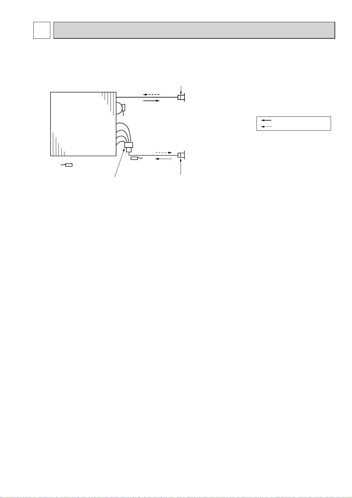
REFRIGERANT SYSTEM DIAGRAM
PLA-RP100BA3
Heat exchanger
Thermistor TH1
(Room temperature)
Thermistor TH5
(Cond./ Eva.temperature)
Thermistor TH2
Pipe temperature(Liquid)
Distributor
with strainer (#50)
Strainer (#50)
Refrigerant GAS pipe connection
(Flare)
Refrigerant flow in cooling
Refrigerant flow in heating
Refrigerant LIQUID pipe connection
(Flare)
Strainer (#50)
11
9
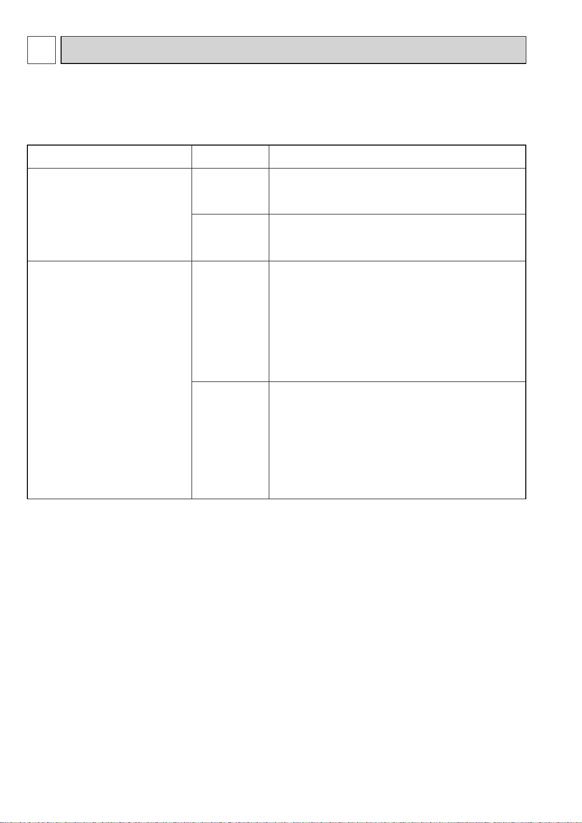
TROUBLESHOOTING
9-1. TROUBLESHOOTING
<Error code display by self-diagnosis and actions to be taken for service (summary)>
Present and past error codes are logged and displayed on the wired remote controller or controller board of outdoor unit.
Actions to be taken for service and the trouble reoccurrence at field are summarized in the table below. Check the contents
below before investigating details.
Unit conditions at service
The trouble is reoccurring.
The trouble is not reoccurring.
Error code
Displayed
Not displayed
Logged
Not logged
Actions to be taken for service (summary)
Judge what is wrong and take a corrective action according
to “9-3. Self-diagnosis action table”.
Conduct troubleshooting and ascertain the cause of the
trouble according to “9-4. Troubleshooting by inferior
phenomena”.
Consider the temporary defects such as the work of
protection devices in the refrigerant circuit including
compressor, poor connection of wiring, noise and etc.
Re-check the symptom, and check the installation
environment, refrigerant amount, weather when the
trouble occurred, matters related to wiring and etc.
Reset error code logs and restart the unit after finishing
service.
There is no abnormality in electrical component,
controller board, remote controller and etc.
Re-check the abnormal symptom.
Conduct trouble shooting and ascertain the cause of
the trouble
inferior phenomena”.
Continue to operate unit for the time being if the cause
is not ascertained.
There is no abnormality concerning of parts such as
electrical component, controller board, remote controller
and etc.
according to “9-4. Troubleshooting
by
12
 Loading...