

Mitsubishi PLA-P3AA.UK, PLA-P4AA.UK, PLA-P5AA.UK, PLA-P6AA.UK, PLA-P3AA1.UK Service Manual
...Page 1
FILTER
CHECK MODE
TEST RUN
ON/OFF
SPLIT-TYPE AIR CONDITIONERS
ON/OFF TEMP
MODEL SELECT
NOT AVAILABLE
CHECK
TEST RUN
˚C
AMPM
AMPM
ON/OFF
CENTRALLY CONTROLLED
ERROR CODE
CLOCK
ON OFF
˚C
CHECK
CHECK MODE
FILTER
TEST RUN
FUNCTION
˚C
1Hr.
NOT AVAILABLE
STAND BY
DEFROST
TEMP.
TECHNICAL & SERVICE MANUAL
No.OC241
REVISED EDITION-A
Series PLA
Indoor unit
[Model names]
PLA-P3AA
PLA-P4AA
PLA-P5AA
PLA-P6AA
Ceiling Cassettes
[Service Ref.]
PLA-P3AA.UK
PLA-P3AA
PLA-P4AA.UK
PLA-P4AA
PLA-P5AA.UK
PLA-P5AA
PLA-P6AA.UK
PLA-P6AA
R407C
1.UK
1.UK
1.UK
1.UK
CONTENTS
• PLA-P3AA1.UK, PLA-P4AA1.UK
PLA-P5AA
1.UK and PLA-P6AA1.UK
are added in REVISED EDITION-A.
Outdoor units PU(H)-P3,4VGAA.UK
and PU(H)-P3,4,5,6YGAA.UK
which are connected to those
indoor units are also added in it.
• Please void OC241.
• Refer to the OCT03 REVISED
EDITION-C as for control relation.
This manual does not cover outdoor units.
When serving them, please refer to
the service manual No.OC180
REVISED EDITION-A, OC261 and
this manual in a set.
1. TECHNICAL CHANGES······························2
2. COMBINA TION OF INDOOR AND OUTDOOR UNITS··3
3. SAFETY PRECAUTION·······························3
4. PART NAMES AND FUNCTIONS ···············5
5. SPECIFICATIONS ······································11
6. DATA ··························································23
7. OUTLINES AND DIMENSIONS·················52
INDOOR UNIT
WIRING DIAGRAM
9.
REFRIGERANT SYSTEM DIAGRAM
·······································53
··············54
8.
10. TROUBLESHOOTING ·······························58
11. DISASSEMBLY PROCEDURE ··················60
12. PARTS LIST···············································63
13. OPTIONAL PARTS ····································68
PLA-P•AA.UK PLA-P•AA
WIRELESS REMOTE
CONTROLLER
1.UK
PLA-P•AA.UK
WIRED REMOTE
CONTROLLER
PLA-P•AA
1.UK
Page 2

1
PLA-P3AA.UK ➔ PLA-P3AA1 PLA-P4AA.UK ➔ PLA-P4AA1.UK
PLA-P5AA.UK ➔ PLA-P5AA1 PLA-P6AA.UK ➔ PLA-P6AA1.UK
● REMOTE CONTROLLER has changed. (PAR-S27A-E ➔ PAR-20MAA-E, PAR-SL95A-E ➔ PAR-SL97A-E)
● Outdoor unit which are connected to PLA-P•AA.UK and PLA-P•AA
TECHNICAL CHANGES
1.UK have been added.
2
Page 3
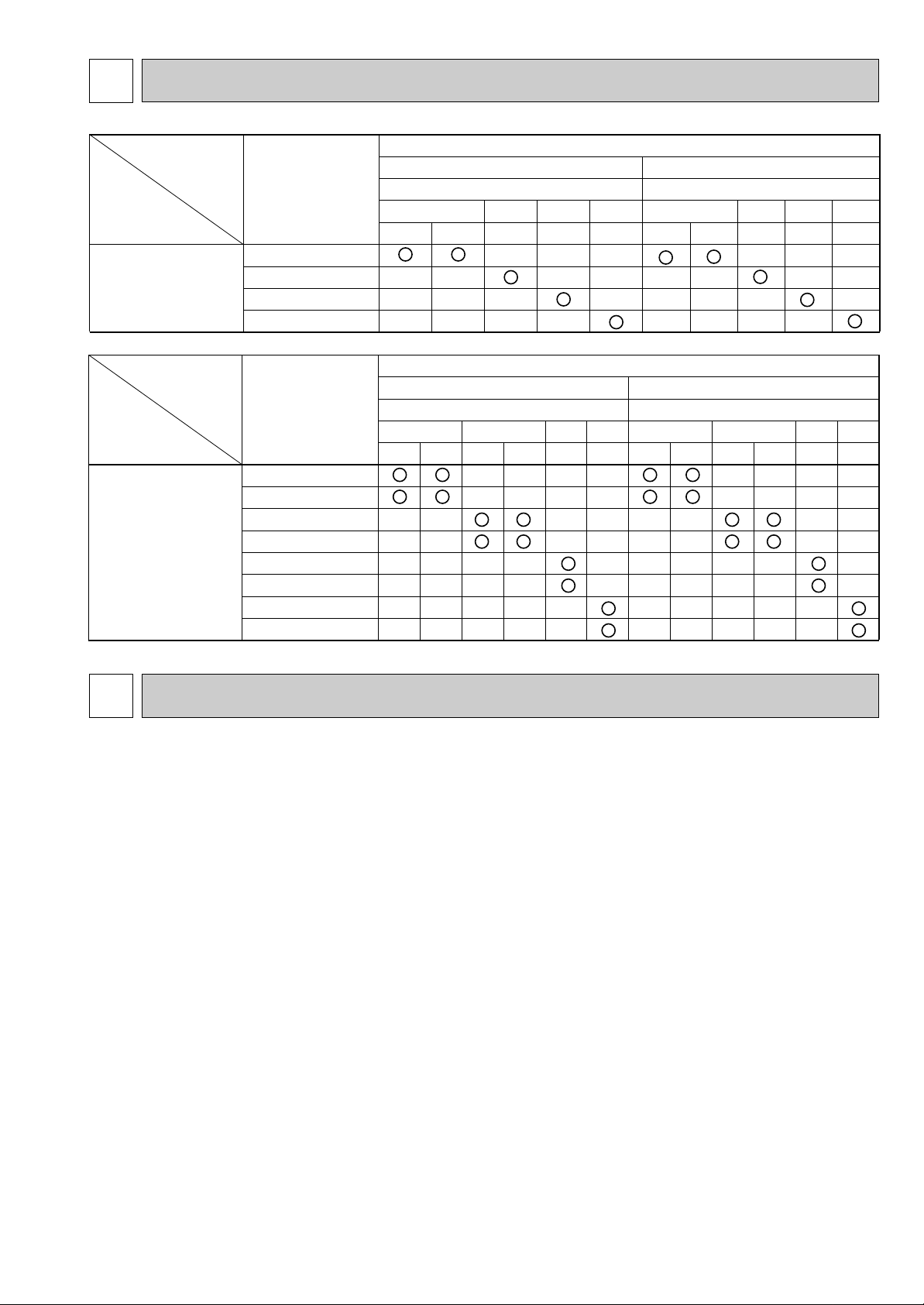
2
Heat pump type
Outdoor unit
PUH-P
Cooling only type
PU-P
Heat pump without
electric heater
or
Cooling only
6
YGA
—
—
—
5
YGA
—
—
—
4
YGA
—
—
—
YGA
—
—
—
VGA
—
—
—
6
YGA
—
—
—
5
YGA
—
—
—
4
YGA
—
—
—
YGA
—
—
—
VGA
—
—
—
Indoor unit
PLA-P3AA.UK
PLA-P4AA.UK
PLA-P5AA.UK
PLA-P6AA.UK
3
3
Heat pump type
Outdoor unit
PUH-P
Cooling only type
PU-P
Heat pump without
electric heater
or
Cooling only
6
YGAA.UK
—
—
—
—
—
—
5
YGAA.UK
—
—
—
—
—
—
YGAA.UK
—
—
—
—
—
—
YGAA.UK
—
—
—
—
—
—
VGAA.UK
—
—
—
—
—
—
VGAA.UK
—
—
—
—
—
—
6
YGAA.UK
—
—
—
—
—
—
5
YGAA.UK
—
—
—
—
—
—
YGAA.UK
—
—
—
—
—
—
YGAA.UK
—
—
—
—
—
—
VGAA.UK
—
—
—
—
—
—
VGAA.UK
—
—
—
—
—
—
Indoor unit
PLA-P3AA.UK
PLA-P3AA
1.UK
PLA-P4AA.UK
PLA-P4AA1.UK
PLA-P5AA.UK
PLA-P5AA1.UK
PLA-P6AA.UK
PLA-P6AA1.UK
3434
COMBINATION OF INDOOR AND OUTDOOR UNITS
3
Cautions for devices that use R407C refrigerant.
· Do not use the existing refrigerant piping.
-The old refrigerant and lubricating oil in the existing piping contains a large amount of chlorine which may cause the lubricating
oil of the new unit to deteriorate.
· Use “low residual oil piping”.
-If there is a large amount of residual oil (hydraulic oil, etc.) inside the piping and joints, deterioration of the lubricating oil will
result.
· Store the piping to be used during installation indoors and keep both ends of the piping sealed until just before
brazing. (Store elbows and other joints in a plastic bag.)
-If dust, dirt, or water enters the refrigerant cycle, deterioration of the oil and compressor trouble may result.
· Use Suniso 4GS or 3GS (small amount) as the lubricating oil to coat flares and flange connection parts.
-The lubricating oil used with the air conditioner is highly hygroscopic. If it is used, water may be mixed in and deterioration
of the lubricating oil may result.
· Use liquid refrigerant to charge the system.
-If gas refrigerant is used to charge the system, the composition of the refrigerant in the cylinder will change and perfor-
mance may drop.
· Do not use a refrigerant other than R407C.
-If another refrigerant (R22, etc.) is used, the chlorine in the refrigerant may cause the lubricating oil to deteriorate.
· Use a vacuum pump with a reverse flow check valve.
-The vacuum pump oil may flow back into the refrigerant cycle and cause the lubricating oil to deteriorate.
SAFETY PRECAUTION
3
Page 4
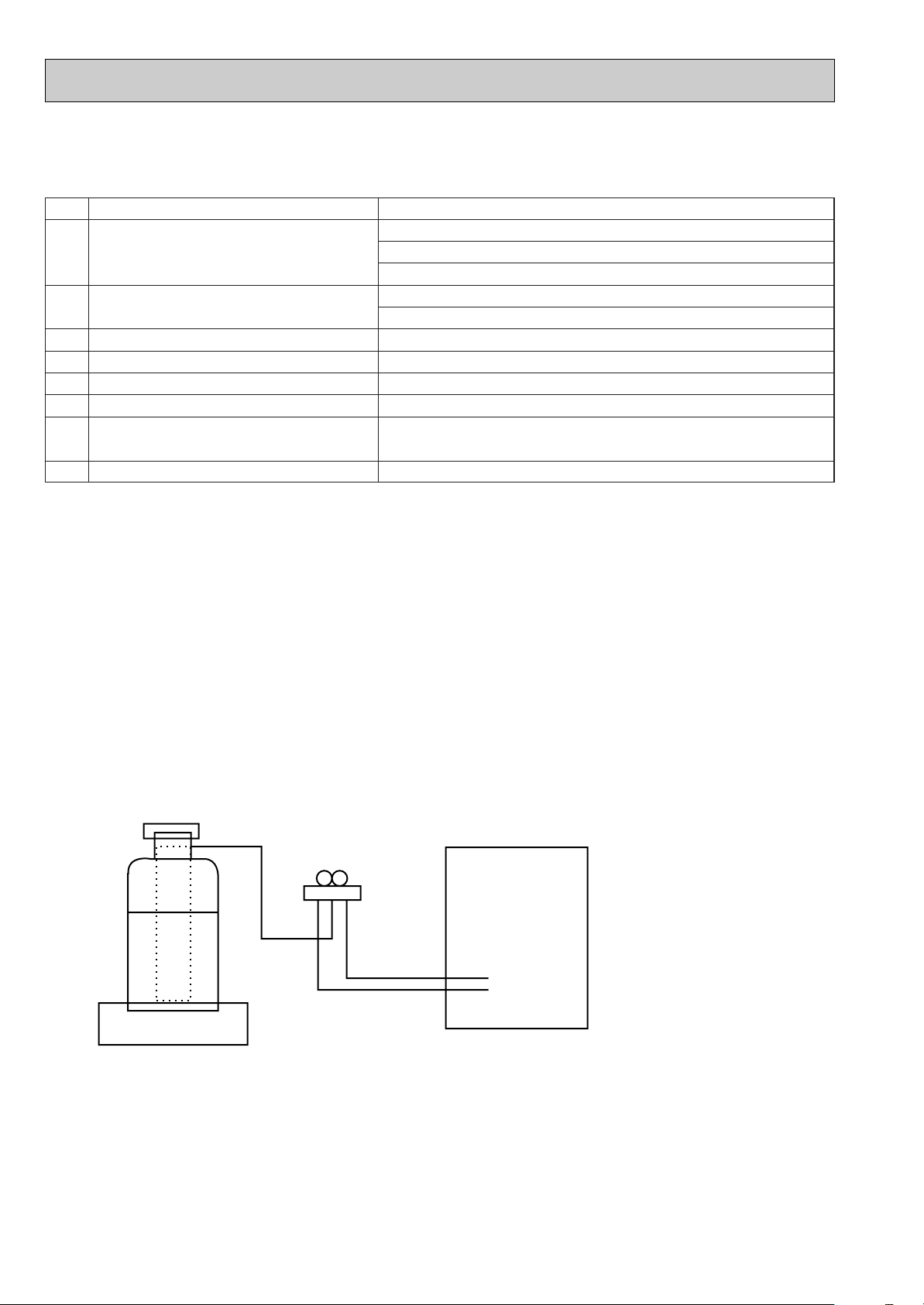
[1] Service tools
Gravimeter
Unit
Use the below service tools as exclusive tools for R407C refrigerant.
No. Tool name Specifications
1 Gauge manifold ·Only for R407C.
·Use the existing fitting SPECIFICATIONS. (UNF7/16)
·Use high-tension side pressure of 35kgf/cm2or over.
2 Charge hose ·Only for R407C.
·Use pressure performance of 52kgf/cm2or over.
3 Electronic scale
4 Gas leak detector ·Use the detector for R134a or R407C.
5 Adapter for reverse flow check. ·Attach on vacuum pump.
6 Refrigerant charge base.
7 Refrigerant cylinder. ·For R407C ·Top of cylinder (Brown)
·Cylinder with syphon
8 Refrigerant recovery equipment.
[2] Notice on repair service
·After recovering all the refrigerant in the unit, work may be started.
·Do not release the refrigerant in the air.
·After completing the repair service, recharge the system with the specified amount of the
liquid refrigerant.
[3] Refrigerant recharging
(1) Refrigerant recharging process
Direct charging from the cylinder.
·Confirm that the cylinder is suitable for syphoning.
·Raise the cylinder and recharge the unit by syphoning liquid refrigerant.
(2) Recharge when refrigerant leakage has occurred.
·After recovering all the refrigerant in the unit, work may be started.
·Do not release the refrigerant in the air.
·After completing the repair service, recharge the system with the specified amount of
the liquid refrigerant.
4
Page 5
4
PAR-S27AA
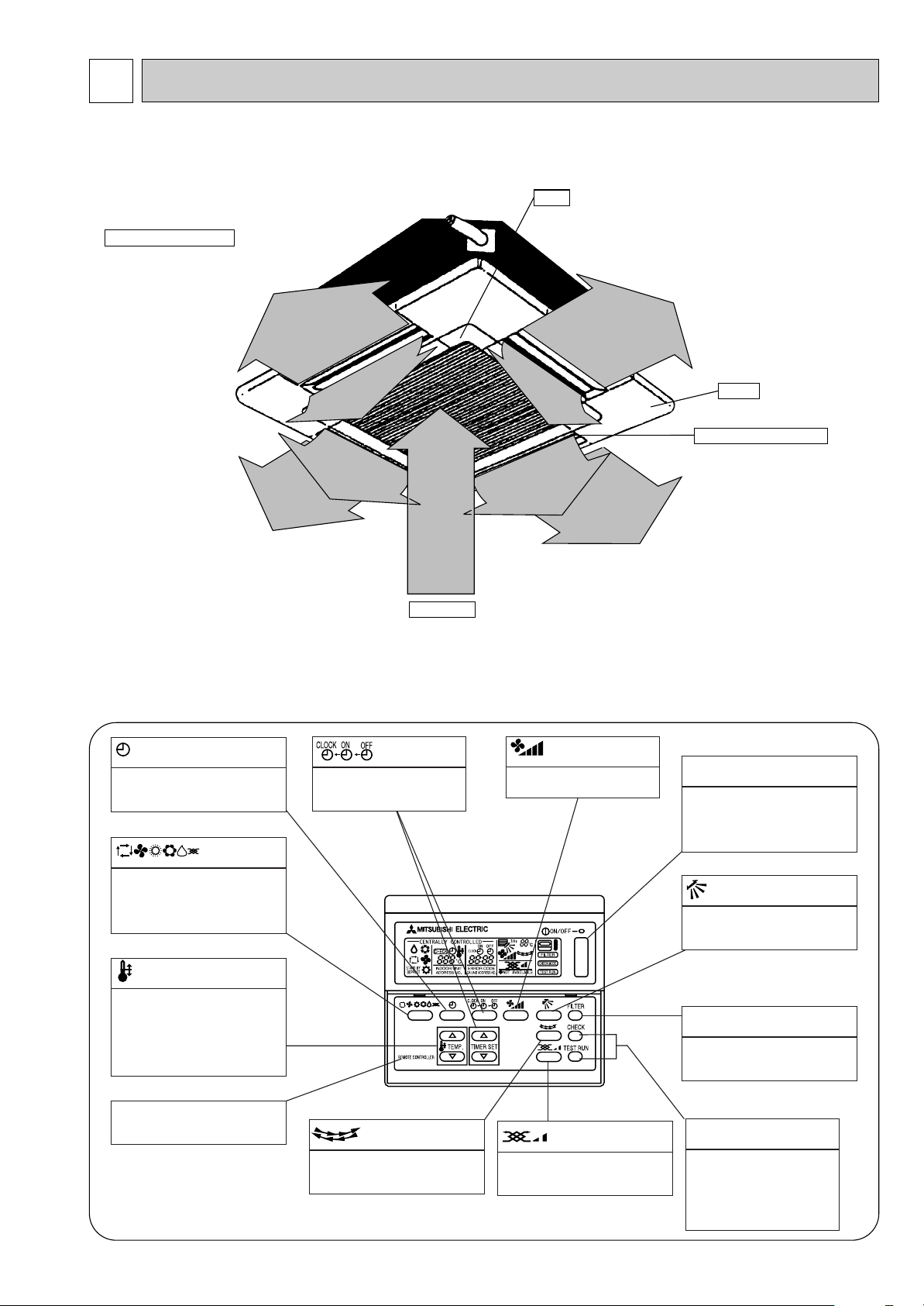
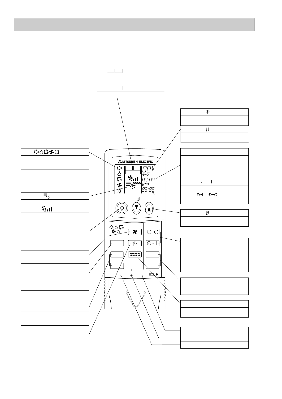
PART NAMES AND FUNCTIONS
● Indoor (Main) Unit
PLA-P3AA.UK, PLA-P4AA.UK, PLA-P5AA.UK, PLA-P6AA.UK
PLA-P3AA1.UK, PLA-P4AA1.UK, PLA-P5AA1.UK, PLA-P6AA1.UK
Filter
Removes dust and pollutants
Horizontal Air Outlet
Sets airflow of horizontal automatically
during cooling or dehumidifying.
from intake air
Grille
Auto Air Swing Vane
Disperses airflow up and
down and adjusts the angle
of airflow direction.
Air Intake
● Wired remote controller
Intakes air from room.
On the controls are set, the same operation mode can be repeated by simply pressing the ON/OFF button.
PLA-P3AA.UK, PLA-P4AA.UK, PLA-P5AA.UK, PLA-P6AA.UK
● Operation buttons
button
This switches between continuous
operation and the timer operation.
button
Press this button to switch the cooling,
electronic dry (dehumidify), automatic
and heating modes.
TEMP. button
This sets the room temperature, The
temperature setting can be performed
in 1°C units
Setting range
Cooling 19°C to 30°C
Heating 17°C to 28°C
button
This sets the current time. start
time and stop time.
button
This sets the ventilation fan
speed.
ON/OFF button
This switches between the operation
and stop modes each time it is
pressed. The lamp on this button
lights during operation.
button
This adjusts the vertical angle of the
ventilation.
FILTER button
This resets the filter cleaning indication display.
This model name of the remote controller is indicated.
button
This switches the horizontal fan
motion ON and OFF.
(Not available for this model.)
button
This sets the ventilation fan speed.
5
CHECK-TEST RUN button
Only press this button to perform an inspection check or test
operation, Do not use it for normal operation.
Page 6
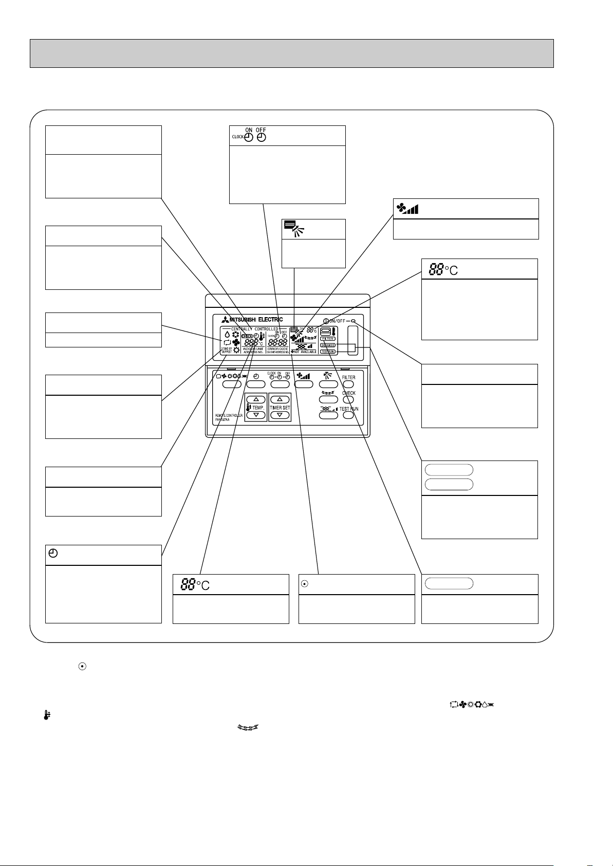
● Display
CENTRALLY
CONTROLLED display
This indicates when the unit is controlled by optional features such as
central control type remote controller.
CHECK display
This indicates when a malfunction
has occurred in the unit which should
be checked.
OPERATION MODE display
This indicates the operation mode.
STANDBY display
The [STANDBY] symbol is only displayed from the time the heating
operation starts until the heated air
begins to blow.
display
The current time , start time and stop
time can be displayed in ten second
intervals by pressing the time setting
button. The start time or stop time is
always displayed during the timer
operation.
display
This displays the air
direction.
In this display example on the bottom left, a condition where all display lamps light is shown for explanation purposes although this differs
from actual operation.
display
The selected fan speed is displayed.
display
The temperature of the suction air is
displayed during operation. The display range is 10° to 35°C. The display flashes 10°C when the actual
temperature is less than 10° and
flashes 35°C when the actual temperature is greater than 35°C.
Operation lamp
This lamp lights during operation,
goes off when the unit stops and
flashes when a malfunction occurs.
DEFROST display
This indicates when the defrost operation is performed.
CHECK MODE
TEST RUN
This display lights in the check mode
or when a test operation is performed.
display
display
This indicates when the continuous
operation and time operation modes
are set.
It also display the time for the timer
operation at the same time as when
it is set.
display
This displays the selected setting
temperature.
display
This lamp lights when electricity is
supplied to the unit.
Caution
● Only the display lights when the unit is stopped and power supplied to the unit.
● When power is turned ON for the first time the (CENTRAL CTRL) display appears to go off momentarily but this is not a
malfunction.
● When the central control remote control unit, which is sold separately, is used the ON-OFF button, button and
TEMP. button do not operate.
● “NOT AVAILABLE” is displayed when the button are pressed.This indicates that this room unit is not equipped
with the fan direction adjustment function and the louver function.
● When power is turned ON for the first time , it is normal that “HO” is displayed on the room temperature indication (For max.
2minutes ).
Please wait until this “HO” indication disappear than start the operation.
FILTER
This lamp lights when the filter need
to be cleaned.
display
6
Page 7
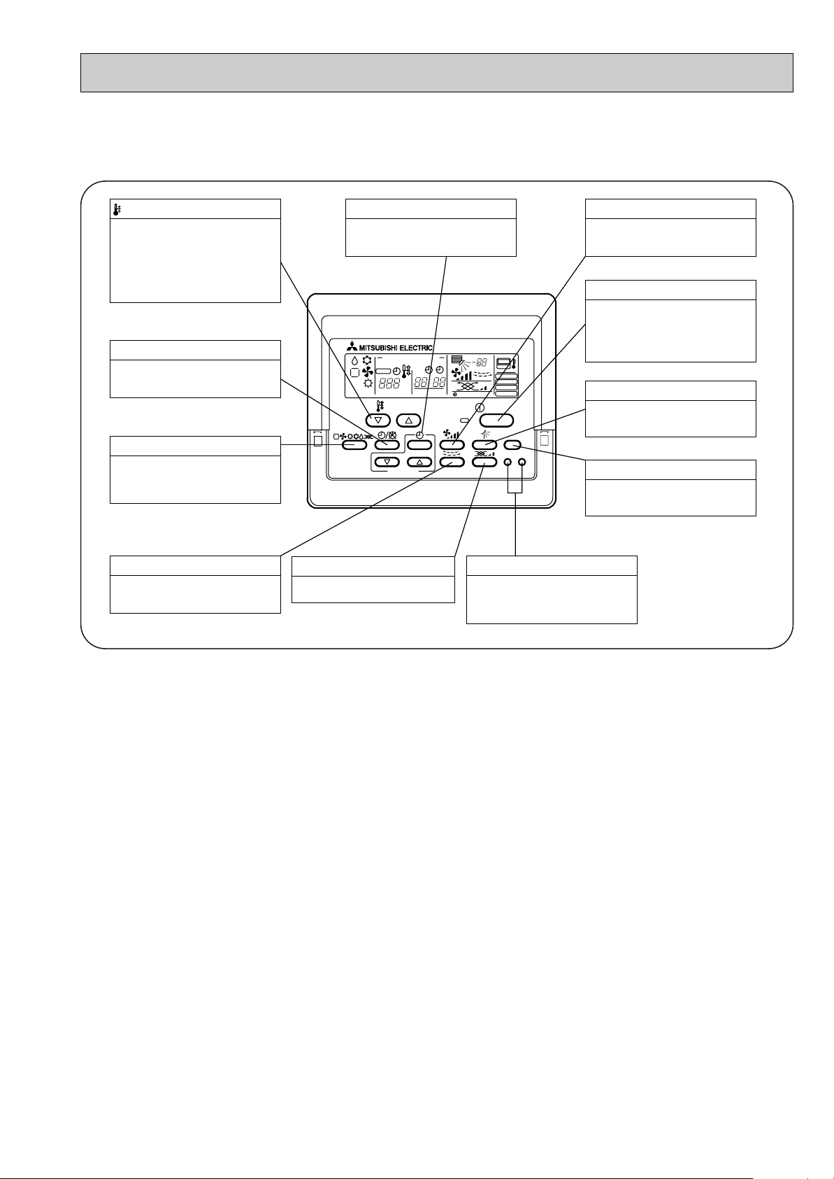
PAR-20MAA
ON/OFF
CENTRALLY CONTROLLED
ERROR CODE
CLOCK
ON OFF
˚C
CHECK
CHECK MODE
FILTER
TEST RUN
FUNCTION
˚C
1Hr.
NOT AVAILABLE
STAND BY
DEFROST
FILTER
CHECK TEST
TEMP.
TIMER SET
This sets the ventilation fan speed.
VENTILATION button
Press this button to switch the cooler,
electronic dry (dehumidify), automatic
and heater modes.
OPERATION SWITCH button
This sets the room temperature. The
temperature setting can be performed
in 1: units
Setting range
Cooler 19: to 30:
Heater 17: to 28:
TEMP. ADJUSTMENT button
This switches between continuous
operation and the timer operation.
TIMER button
This switches between the operation
and stop modes each time it is pressed.
The lamp on this button lights during
operation.
ON/OFF button
Only press this button to perform an
inspection check or test operation.
Do not use it for normal operation.
CHECK-TEST RUN button
This switch the horizontal fan motion
ON and OFF.
(Not available for this model.)
LOUVER button
This adjusts the vertical angle of the
ventilation.
AIR DIRECTION button
This resets the filter service indication
display
FILTER button
This sets the current time, start time
and stop time.
TIME SETTING button
This sets the ventilation fan speed.
AIR SPEED button
PLA-P3AA1.UK, PLA-P4AA1.UK, PLA-P5AA1.UK, PLA-P6AA1.UK
● Operation buttons
7
Page 8
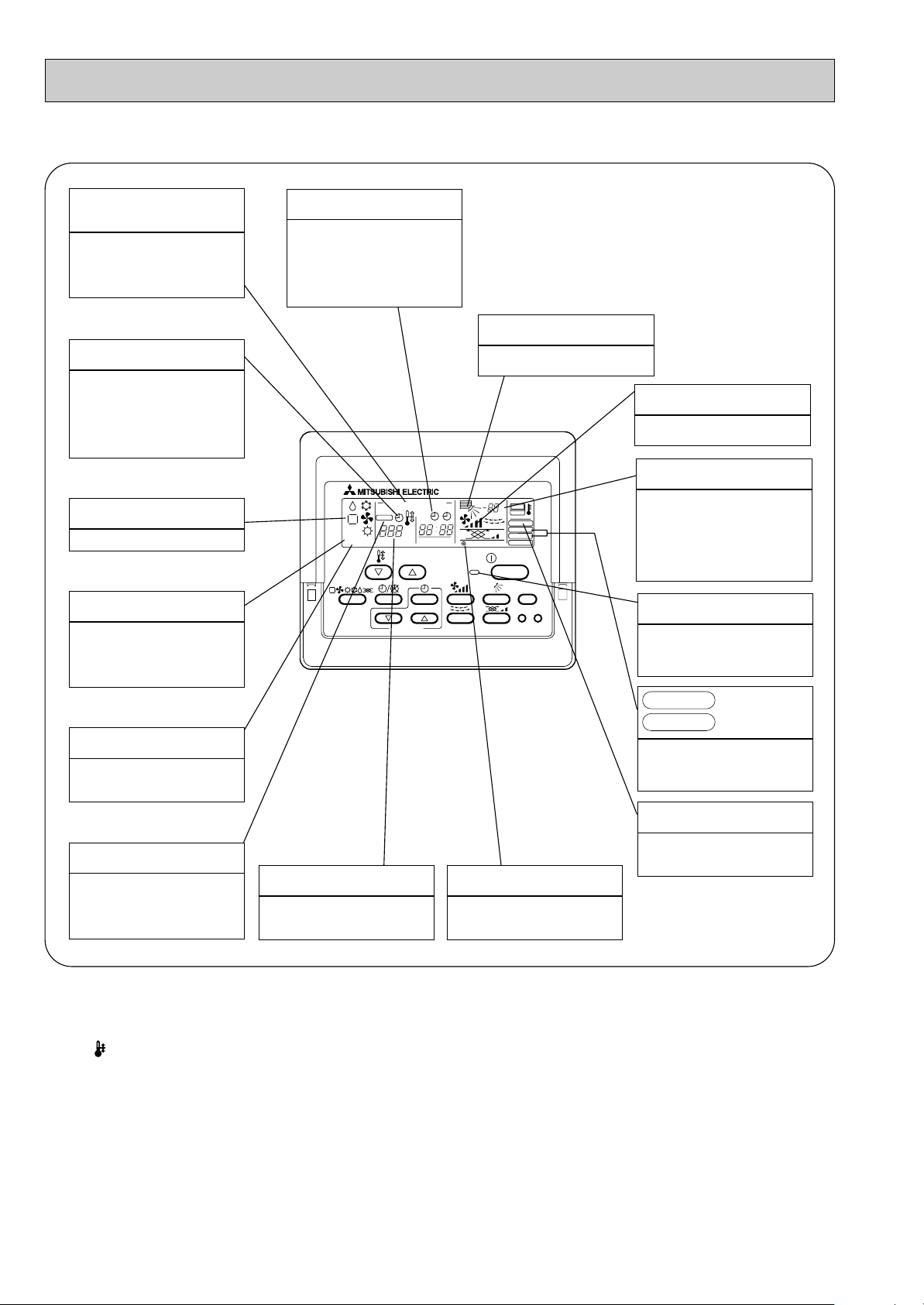
● Display
PAR-20MAA
ON/OFF
CENTRALLY CONTROLLED
ERROR CODE
CLOCK
ON OFF
˚C
CHECK
CHECK MODE
FILTER
TEST RUN
FUNCTION
˚C
1Hr.
NOT AVAILABLE
STAND BY
DEFROST
FILTER
CHECK TEST
TEMP.
TIMER SET
CENTRALLY
CONTROLLED display
This indicates when the unit is con-
trolled by optional features such as
central control type remote controller.
TIMER display
This indicates when the continuous
operation and time operation modes
are set.
It also display the time for the timer
operation at the same time as when
it is set.
OPERATION MODE display
This indicates the operation mode.
STANDBY display
The [STANDBY] symbol is only dis-
played from the time the heating
operation starts unit the heated air
begins to blow.
DEFROST display
This indicates when the defrost oper-
ation is performed.
CLOCK display
The current time , start time and stop
time can be displayed in ten second
intervals by pressing the time switch
button. The start time or stop time is
always displayed during the timer
operation.
In this display example on the bot-
tom left, a condition where all display lamps light is shown for explanation purposes although this differs
from actual operation.
AIR DIRECTION display
This displays the air direction.
AIR SPEED display
The selected fan speed is displayed.
ROOM TEMPERATURE display
The temperature of the suction air
is displayed during operation. The
display range is 8°C to 39°C. The
display flashes 8°C when the actual
temperature is less than 8°C and
flashes 39°C when the actual temperature is greater than 39°C.
Operation lamp
This lamp lights during operation,
goes off when the unit stops and
flashes when a malfunction occurs.
This display lights in the check mode
or when a test operation is performed.
CHECK MODE
TEST RUN
display
FILTER display
CHECK display
This indicates when a malfunction
has occurred in the unit which should
be checked.
SET TEMPERATURE display
This displays the selected setting
temperature.
Caution
● Only the Power display lights when the unit is stopped and power supplied to the unit.
● When the central control remote control unit, which is sold separately, is used the ON-OFF button, operation switch button
and TEMP. adjustment button do not operate.
● “NOT AVAILABLE” is displayed when the Air speed button are pressed.This indicates that this room unit is not equipped
with the fan direction adjustment function and the louver function.
● When power is turned ON for the first time, it is normal that “H0” is displayed on the room temperature indication (For max.
2minutes). Please wait until this “H0” indication disappear then start the operation.
POWER display
This lamp lights when electricity is
supplied to the unit.
This lamp lights when the filter need
to be cleaned.
8
Page 9
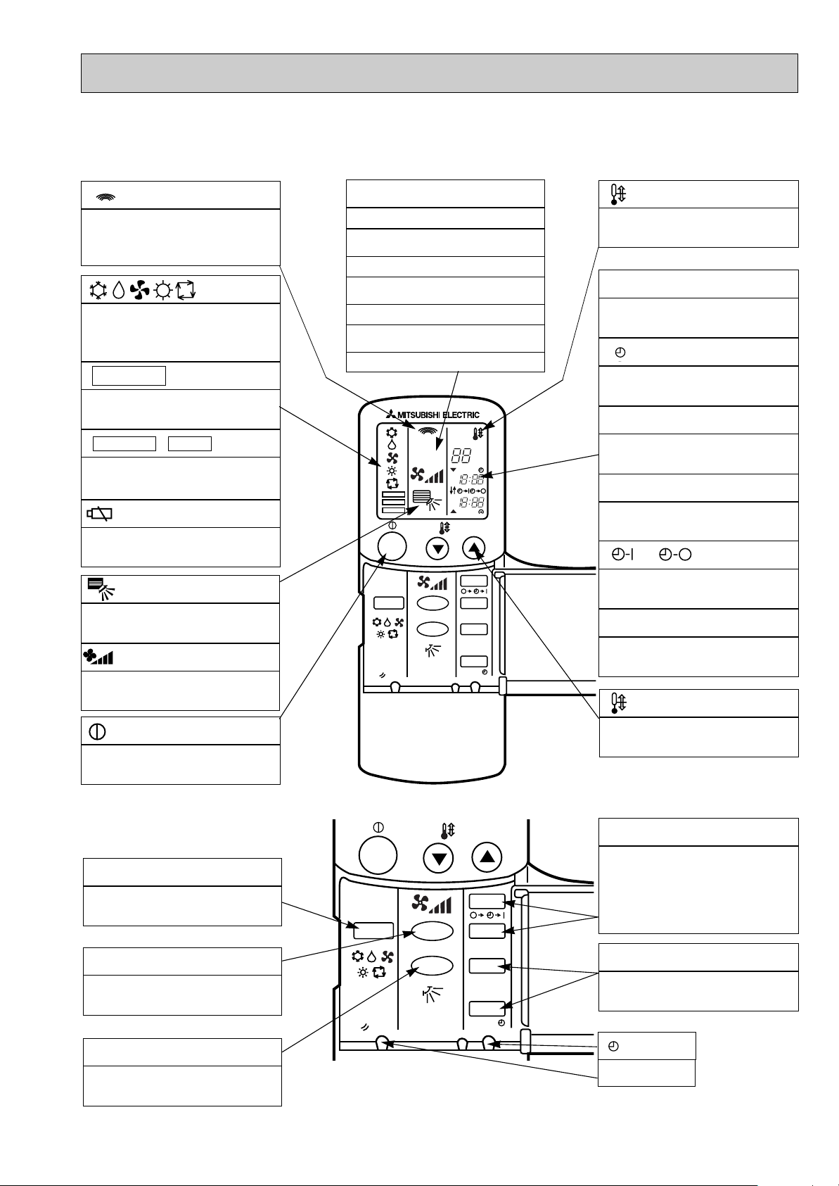
● Wireless remote controller
ON/OFF
RESET
MODE FAN
VANE
TEMP.
START
STOP
HR.
MIN.
ON/OFF
CHECK
ADDRESS
UNIT No.
FUNCTION No.
SELECTION No.
AM
PM
RESET
AM
PM
TEST RUN
FUNCTION
˚C
MODE FAN
VANE
TEMP.
START
STOP
HR.
MIN.
PLA-P3AA.UK, PLA-P4AA.UK, PLA-P5AA.UK, PLA-P6AA.UK
● When cover is open.
display
Lights up while transmission to the indoor unit
is mode using switches.
display
OPERATION MODE display
Operation mode display indicates which operation mode is in effect.
• FUNCTION
Lights up when function are set.
display
• TEST RUN • CHECK display
CHECK&TEST RUN display indicates that the
unit is being checked or test-run.
display
Displays when batteries are dead.
display
ADDRESS display
Displays the refrigerant address.
UNIT NO. display
Displays the number of unit..
FUNCTION NO. display
Displays the mode.
SELECTION NO. display
Displays the selection number..
display
SET TEMP. display indicates desired temperature set.
CLOCK display
DIsplays the current time.
“ ”display
Flashes when the current time is displayed.
TIMER display
Displays when in timer operation or when setting timer.
➡
“ ” “ ” display
➡
Displays the order of timer operation.
“ ” “ ” display
Displays whether timer is on or off.
The vertical direction of airflow is indicated.
display
FAN SPEED display indicates which fan
speed has been selected.
display
The unit is turned ON and OFF alternately
each time the button is pressed.
● When cover is open.
MODE SELECT button
Used to switch the operation mode between
cooling , drying , blowing , heating and auto
mode.
FAN SPEED SELECT button
Used to change the fan speed.
VANE CONTROL button
Used to change the airflow direction.
▼
“ ” “ ” display
Displays when the current time and the timer
time can be changed.
▼
TEMP. button
SET TEMPERATURE button sets any desired
room temperature.
TIMER CONTROL buttons
STOP (OFF timer): when this switch is set,
the air conditioner will be automatically
stopped at the preset time.
START(ON timer): when this switch is set, the
air conditioner will be automatically started at
the preset time.
HR. and MIN.buttons
Buttons used to set the “hour and minute” of
the current time and timer settings.
button
RESET button
9
Page 10
PLA-P3AA1.UK, PLA-P4AA1.UK, PLA-P5AA1.UK, PLA-P6AA1.UK
ON/OFF TEMP
FAN
VANE
TEST RUN
AUTO STOP
AUTO START
h
min
LOUVER
MODE
CHECK
RESETSET CLOCK
MODEL SELECT
NOT AVAILABLE
CHECK
TEST RUN
˚C
AMPM
AMPM
VANE CONTROL button
Used to change the air flow direction.
CLOCK button
RESET button
SET button
ON/OFF button
The unit is turned ON and OFF alternately
each time the button is pressed.
LOUVER button
This switch the horizontal fan motion ON
and OFF.
(Not available for this model.)
MODE SELECT button
Used to switch the operation mode between
cooling, drying, blowing, heating and auto
mode.
CHECK-TEST RUN button
Only press this button to perform an inspection check or test operation.
Do not use it for normal operation.
FAN SPEED SELECT button
Used to change the fan speed.
TIMER display
Displays when in timer operation or when
setting timer.
button
SET TEMPERATURE button sets any desired
room temperature.
CLOCK display
Displays the current time.
“ ” “ ” display
Displays the order of timer operation.
“ ” “ ” display
Displays whether timer is on or off.
w In case the outdoor unit is cool only type,
the heating mode is not available.
Buttons used to set the “hour and minute” of
the current time and timer settings.
h and min buttons
display
SET TEMP. display indicates desired temperature set.
display
FAN SPEED display indicates which fan
speed has been selected.
display
The vertical direction of air flow is indicated.
display
Blinks when model is selected.
display
Lights up while transmission to the indoor
unit is mode using switches.
display
CHECK&TEST RUN display indicates that
the unit is being checked or test-run.
display
OPERATION MODE display
Operation mode display indicates which operation mode is in effect.
TIMER CONTROL buttons
AUTO STOP (OFF timer): when this switch
is set, the air conditioner will be automatically stopped at the preset time.
AUTO START (ON timer): when this switch
is set, the air conditioner will be automatically started at the preset time.
MODEL SELECT
CHECK
TEST RUN
10
Page 11
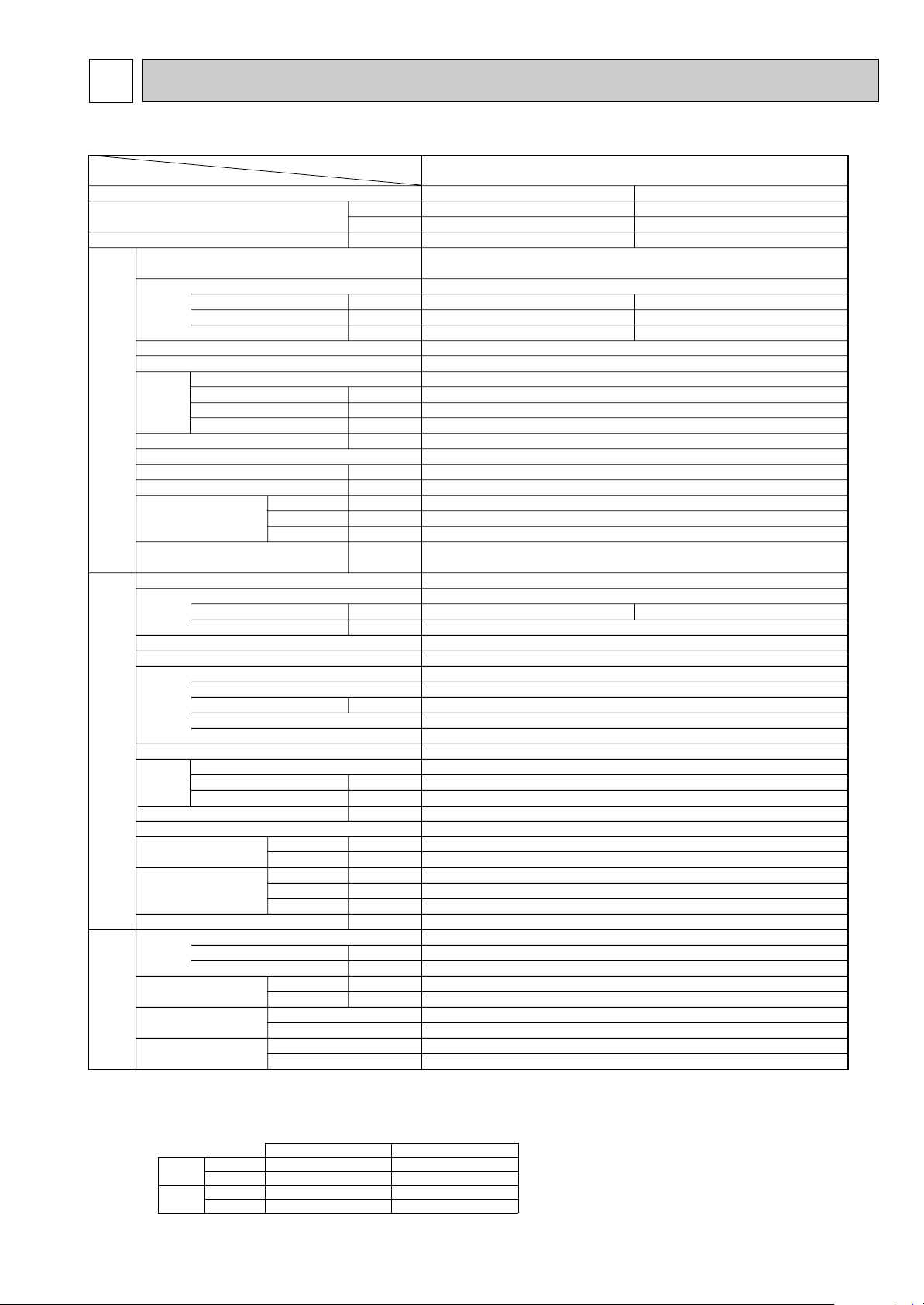
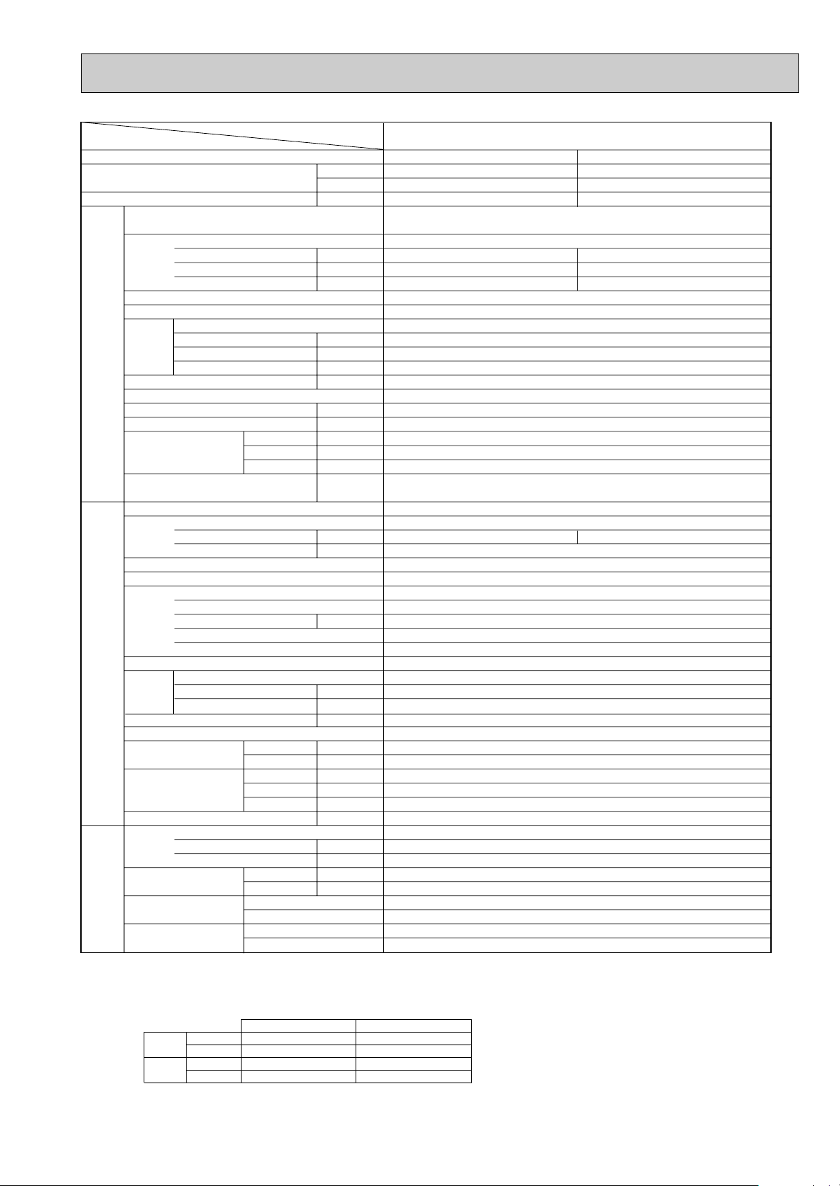
5
Service Ref.
Item
Function
Capacity
Btu/h
W
Total input
Service Ref.
Power supply (phase, cycle,voltage)
Input k W
Running current A
Starting current A
External finish (Panel)
Heat exchanger
Fan
Fan (drive) o No.
Fan motor output kW
Airflow (Lo-Mi2-Mi1-Hi)
K / min (CFM)
External static pressure Pa (mmAq)
Booster heater kW
Operation control & Thermostat
Sound level (Lo-Mi2-Mi1-Hi) dB
Unit drain pipe I.D. mm (in.)
Dimensions
Indoor unit
W mm (in.)
D mm (in.)
H mm (in.)
Weight
kg (lbs.)
Service Ref.
Power supply (phase, cycle, voltage)
Running current A
Starting current A
External finish
Refrigerant control
Compressor
Model
Motor output kW
Starter type
Protection devices
Heat exchanger
Fan (drive) o No.
Fan Fan motor output kW
Airflow K
/ min (CFM)
Crankcase heater W
Defrost method
Sound level
Dimensions
Cooling dB
Heating dB
W mm (in.)
D mm (in.)
H mm (in.)
Outdoor unitRefrigerant piping
Weight kg (lbs.)
Refrigerant
Charge kg (lbs.)
Oil (Model) L
Pipe size O.D.
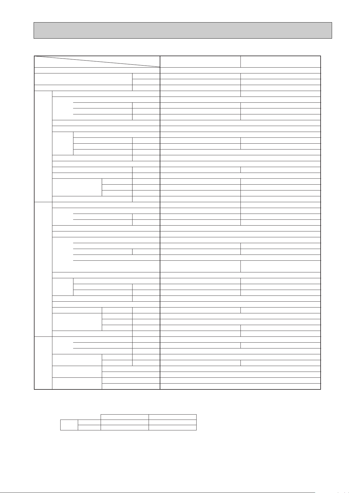
PLA-P3AA.UK
Cooling Heating
26,600 31,700
7,800 9,300
3.51 3.65
PLA-P3AA.UK
Single phase, 50Hz, 220-230-240V
0.17 0.17
0.81 0.81
1.0 1.0
Munsell 0.70Y 8.59/0.97
Plate fin coil
Turbo fan (direct) o 1
0.070
15-16-18-20 (530-565-635-705)
0 (direct blow)
—
Remote controller & built-in
28-30-32-34
32 (1-1/4)
UNIT : 840 (33-1/16) PANEL : 950 (37-3/8)
UNIT : 840 (33-1/16) PANEL : 950 (37-3/8)
UNIT : 258 (10-1/2) PANEL : 30 (1-3/16)
UNIT : 24 (53)
PUH-P3VGA
/ PUH-3YGA
Single phase, 50Hz, 220-230-240V / 3 phase, 50Hz, 380-400-415V (4wires)
14.64/5.46 15.43/5.76
93/41
Munsell 5Y 8/1
Linear expansion valve
Hermetic
NE52VNJM / NE52YDJM
2.5
Line start
Internal thermostat, HP switch, Discharge thermo. / Thermal relay Discharge thermo, HP switch, Anti-phase protector.
Plate fin coil
Propeller (direct) o 1
0.070
50 (1,770)
38
Reverse cycle
49
51
900 (35-7/16)
330+20 (13+3/4)
855 (33-5/8)
82 (181)
R407C
3.7 (8.2)
1.6 (MEL56)
9.52 (3/8)
15.88 (5/8)
Flared
Flared
Max. 50m
Max. 50m
Liquid mm (in.)
Gas mm (in.)
Connection method
Indoor side
Outdoor side
NOTE: 1. Rating conditions (ISO T1)
Cooling Indoor : D.B. 27: (80˚F) W.B. 19: (66˚F) Outdoor : D.B. 35: (95˚F) W.B. 24: (75˚F)
Heating Indoor: D.B. 20: (68˚F) Outdoor : D.B. 7: (45˚F) W.B. 6: (43˚F)
Refrigerant piping length (one way) : 5m (16ft.)
2. Guaranteed operating range
Indoor Outdoor
Cooling
Upper limit
D.B. 35˚C, W.B. 22.5˚C
D.B. 46˚C
Lower limit
D.B. 19˚C, W.B. 15˚C D.B. -5˚C
Heating
Upper limit
D.B. 28˚C
D.B. 24˚C, W.B. 18˚C
Lower limit
D.B. 17˚C
D.B. -11˚C, W.B. -12˚C
Between the indoor &
outdoor units
Height difference
Piping length
3. Above data based on indicated voltage
Indoor unit Single phase 240V 50Hz
Outdoor unit Single phase 240V 50Hz / 3 phase 415V 50Hz
kW
PANEL: 5 (11)
SPECIFICATIONS
1.Heat pump type
11
Page 12

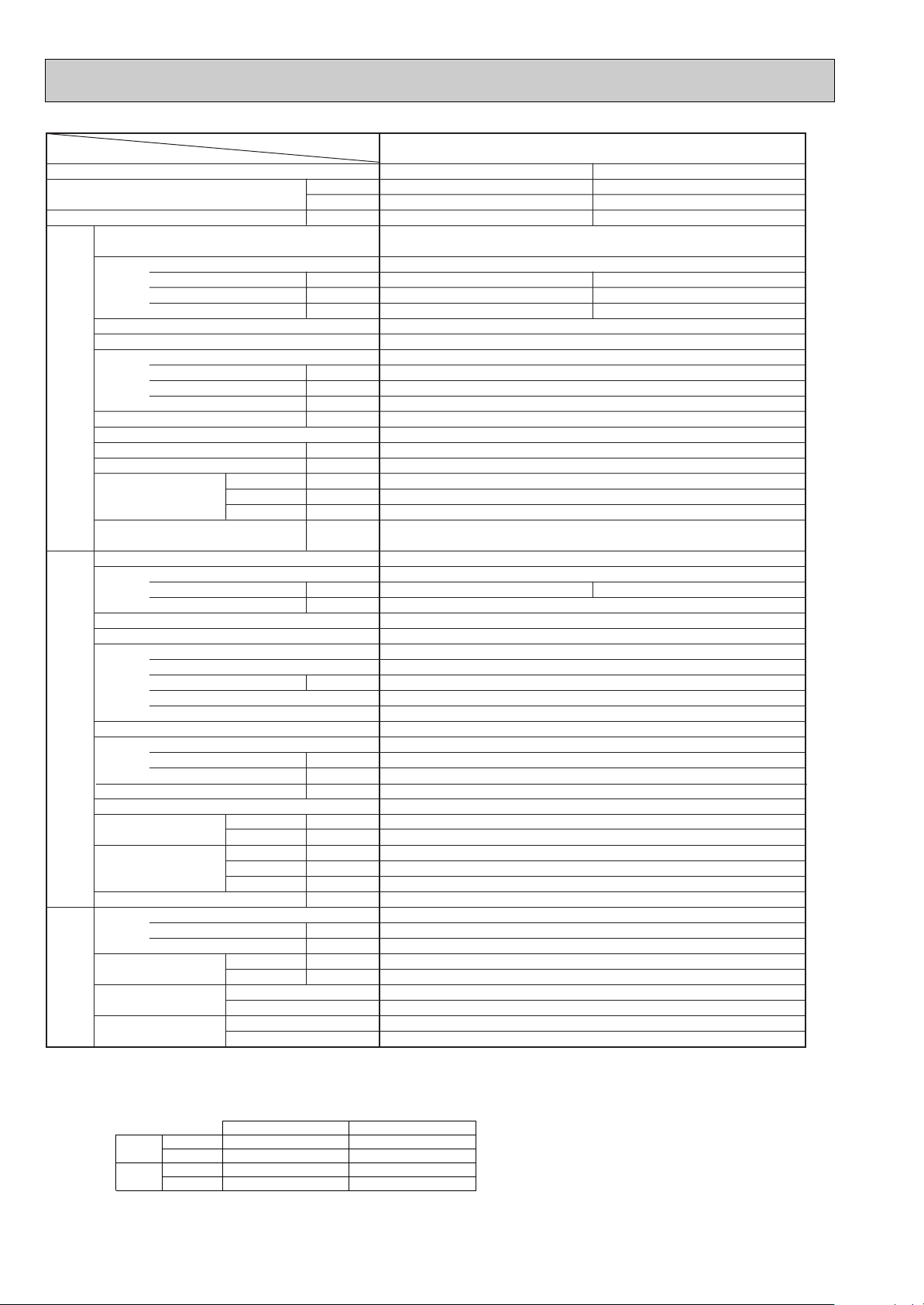
Service Ref.
Item
Function
Capacity
Btu/h
W
Total input k W
Service Ref.
Power supply (phase, cycle,voltage)
Input k W
Running current A
Starting current A
External finish (Panel)
Heat exchanger
Fan
Fan (drive) o No.
Fan motor output kW
Airflow (Lo-Mi2-Mi1-Hi)
K / min (CFM)
External static pressure Pa (mmAq)
Booster heater kW
Operation control & Thermostat
Sound level (Lo-Mi2-Mi1-Hi) dB
Unit drain pipe I.D. mm (in.)
Dimensions
Indoor unit
W mm (in.)
D mm (in.)
H mm (in.)
Weight
kg (lbs.)
Service Ref.
Power supply (phase, cycle, voltage)
Running current A
Starting current A
External finish
Refrigerant control
Compressor
Model
Motor output kW
Starter type
Protection devices
Heat exchanger
Fan (drive) o No.
Fan Fan motor output kW
Airflow
K / min (CFM)
Crankcase heater W
Defrost method
Sound level
Dimensions
Cooling dB
Heating dB
W mm (in.)
D mm (in.)
H mm (in.)
Outdoor unitRefrigerant piping
Weight kg (lbs.)
Refrigerant
Charge kg (lbs.)
Oil (Model) L
Pipe size O.D.
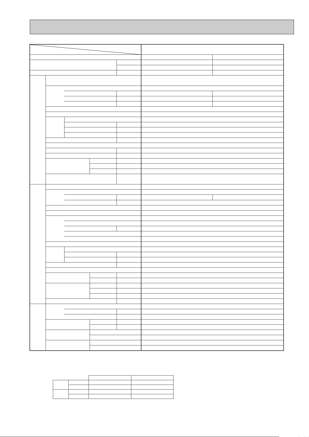
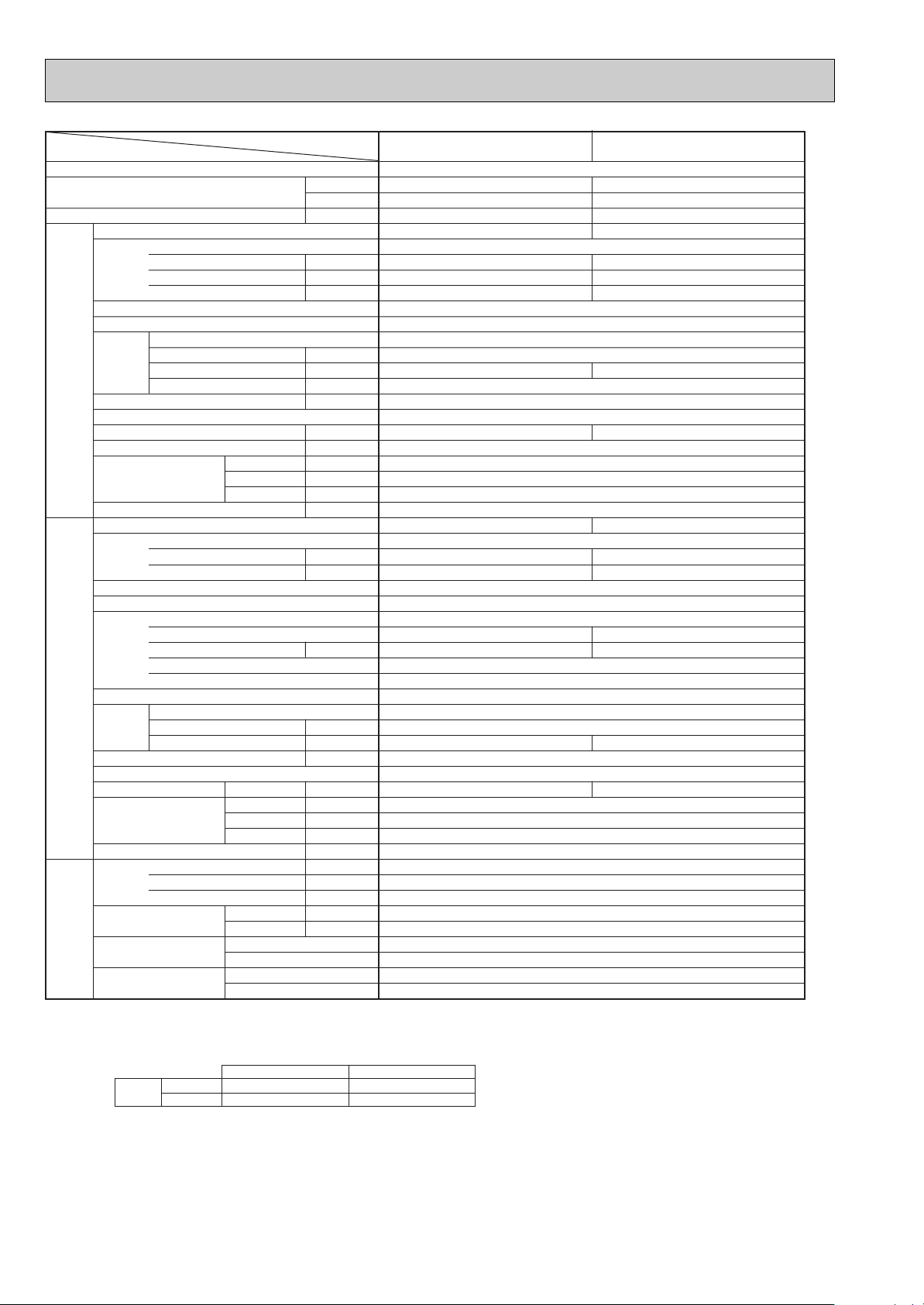
PLA-P4AA.UK
Cooling Heating
33,100 36,200
9,700 10,600
3.62 3.80
PLA-P4AA.UK
Single phase, 50Hz, 220-230-240V
0.26 0.26
1.25 1.25
2.0 2.0
Munsell 0.70Y 8.59/0.97
Plate fin coil
Turbo fan (direct) o 1
0.120
20-23-26-28 (705-810-920-990)
0 (direct blow)
—
Remote controller & built-in
33-36-39-41
32 (1-1/4)
UNIT : 840 (33-1/16) PANEL : 950 (37-3/8)
UNIT : 840 (33-1/16) PANEL : 950 (37-3/8)
UNIT : 298 (11-3/4) PANEL : 30 (1-3/16)
UNIT : 30 (66) PANEL : 5 (11)
PUH-P4YGA
3 phase, 50Hz, 380-400-415V (4wires)
5.49 5.79
45
Munsell 5Y 8/1
Linear expansion valve
Hermetic
NE56YDJM
2.7
Line start
Anti-phase protector, Thermal relay, Discharge thermo, HP switch
Plate fin coil
Propeller (direct) o 2
0.070+0.070
85 (3,000)
38
Reverse cycle
51
53
900 (35-7/16)
330+20 (13+3/4)
1,260 (49-5/8)
96 (212)
R407C
4.0 (8.8)
1.6 (MEL56)
9.52 (3/8)
19.05 (3/4)
Flared
Flared
Max. 50m
Max. 50m
Liquid mm (in.)
Gas mm (in.)
Connection method
Indoor side
Outdoor side
Between the indoor &
outdoor units
Height difference
Piping length
NOTE: 1. Rating conditions (ISO T1)
Cooling Indoor : D.B. 27: (80˚F) W.B. 19: (66˚F) Outdoor : D.B. 35: (95˚F) W.B. 24: (75˚F)
Heating Indoor: D.B. 20: (68˚F) Outdoor : D.B. 7: (45˚F) W.B. 6: (43˚F)
Refrigerant piping length (one way) : 5m (16ft.)
2. Guaranteed operating range
3. Above data based on indicated voltage
Indoor unit Single phase 240V 50Hz
Outdoor unit 3 phase 415V 50Hz
Indoor Outdoor
Cooling
Upper limit
D.B. 35˚C, W.B. 22.5˚C
D.B. 46˚C
Lower limit
D.B. 19˚C, W.B. 15˚C D.B. -5˚C
Heating
Upper limit
D.B. 28˚C
D.B. 24˚C, W.B. 18˚C
Lower limit
D.B. 17˚C
D.B. -11˚C, W.B. -12˚C
12
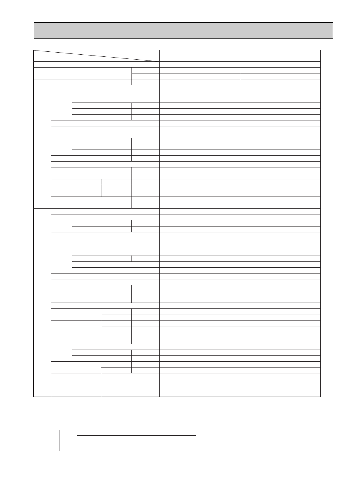
Page 13
Item
Service Ref.
Function
Capacity
Btu/h
Total input k W
Service Ref.
Power supply (phase, cycle,voltage)
Input k W
Running current A
Starting current A
External finish (Panel)
Heat exchanger
Fan (drive) o No.
Fan
Indoor unit
Booster heater kW
Fan motor output kW
Airflow (Lo-Mi2-Mi1-Hi)
K / min (CFM)
External static pressure Pa (mmAq)
Operation control & Thermostat
Sound level (Lo-Mi2-Mi1-Hi) dB
Unit drain pipe I.D. mm (in.)
W mm (in.)
Dimensions
D mm (in.)
H mm (in.)
Weight
kg (lbs.)
Service Ref.
Power supply (phase, cycle, voltage)
Running current A
Starting current A
External finish
Refrigerant control
Compressor
Model
Motor output kW
Starter type
Protection devices
Heat exchanger
Outdoor unitRefrigerant piping
Fan Fan motor output kW
Fan (drive) o No.
Airflow
K / min (CFM)
Crankcase heater W
Defrost method
Sound level
Cooling dB
Heating dB
W mm (in.)
Dimensions
D mm (in.)
H mm (in.)
Weight kg (lbs.)
Refrigerant
Charge kg (lbs.)
Oil (Model) L
Pipe size O.D.
Connection method
Between the indoor &
outdoor units
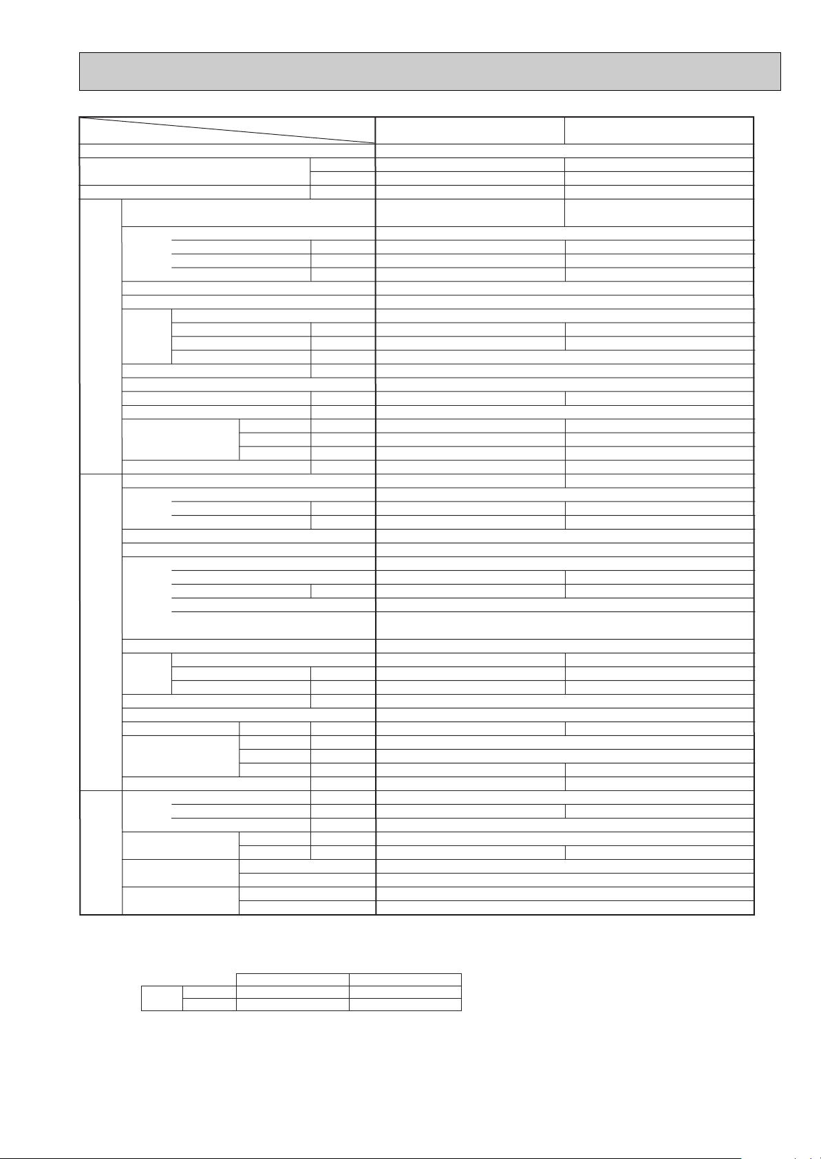
NOTE: 1. Rating conditions (ISO T1)
Cooling : Indoor: D.B. 27: (80˚F) W.B. 19: (66˚F) Outdoor: D.B. 35: (95˚F) W.B. 24: (75˚F)
Heating : Indoor: D.B. 20: (68˚F) Outdoor: D.B. 7: (45˚F) W.B. 6: (43˚F)
Refrigerant piping length (one way) : 5m (16ft.)
2. Guaranteed operating range
Upper limit D.B. 35:, W.B. 22.5: D.B. 46:
Cooling
Lower limit D.B. 19 :, W.B. 15: D.B. -5:
Upper limit D.B. 28
Heating
Lower limit D.B. 17: D.B. -11:, W.B. -12:
Liquid mm (in.)
Gas mm (in.)
Indoor side
Outdoor side
Height difference
Piping length
Indoor Outdoor
:
W
Internal thermostat, Anti-phase protector, Thermal relay, HP switch, LP switch, Discharge thermo.
D.B. 24 :, W.B. 18:
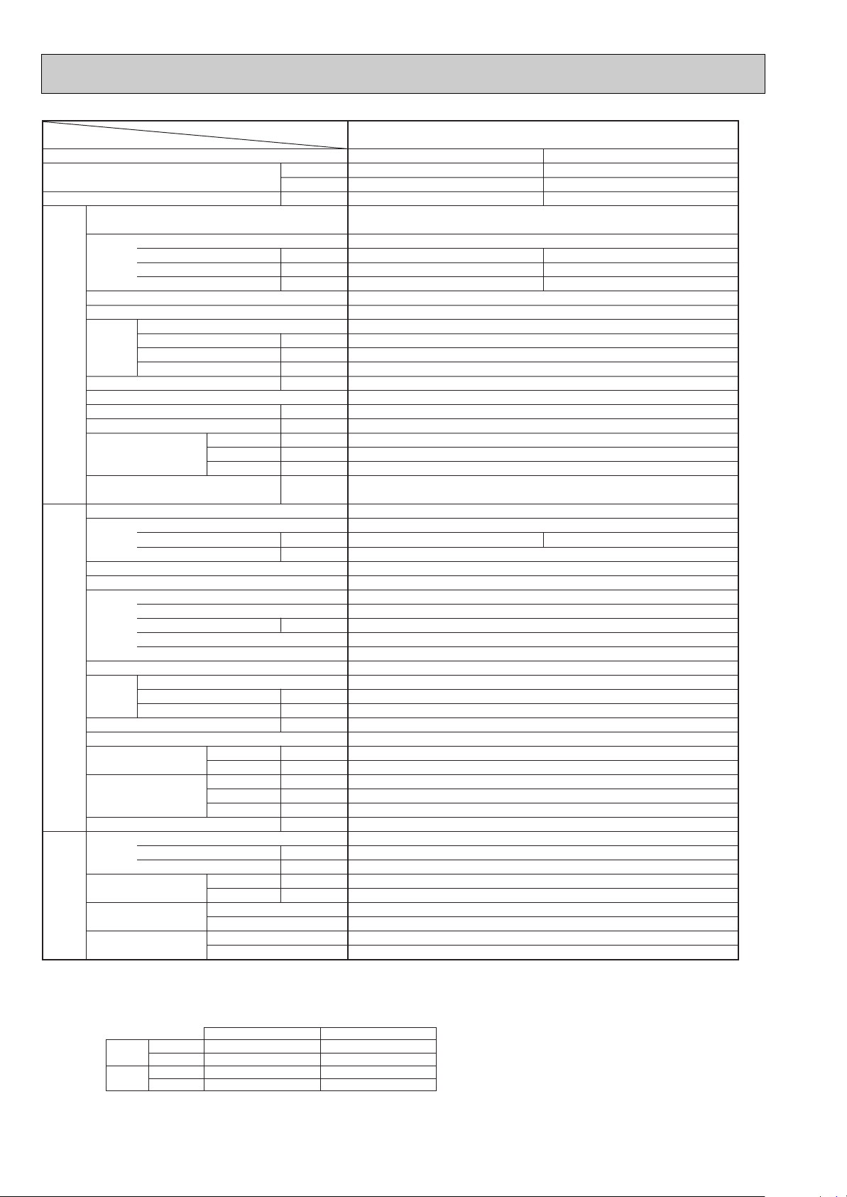
PLA-P5AA.UK
Cooling Heating
43,700 54,600
12,800 16,000
5.55 5.93
PLA-P5AA.UK
Single phase, 50Hz, 220-230-240V
0.30 0.30
1.43 1.43
2.0 2.0
Munsell 0.70Y 8.59/0.97
Plate fin coil
Turbo fan (direct) o 1
0.120
22-25-28-30 (775-880-990-1,060)
0 (direct blow)
—
Remote controller & built-in
35-38-41-43
32 (1-1/4)
UNIT : 840 (33-1/16) PANEL : 950 (37-3/8)
UNIT : 840 (33-1/16) PANEL : 950 (37-3/8)
UNIT : 298 (11-3/4) PANEL : 30 (1-3/16)
UNIT : 30 (66) PANEL : 5 (11)
PUH-P5YGA
3 phase, 50Hz, 380-400-415V (4wires)
8.39 8.74
79
Munsell 5Y 8/1
Linear expansion valve
Hermetic
HE86YAA
4.3
Line start
Plate fin coil
Propeller (direct) o 2
0.075+0.075
95 (3,360)
38
Reverse cycle
53
55
1,050 (41-5/16)
330+20 (13+3/4)
1,260 (49-5/8)
122 (269)
R407C
5.8 (12.8)
2.0 (MEL32)
9.52 (3/8)
19.05 (3/4)
Flared
Flared
Max. 50m
Max. 50m
3. Above data based on indicated voltage
Indoor unit Single phase 240V 50Hz
Outdoor unit 3 phase 415V 50Hz
13
Page 14
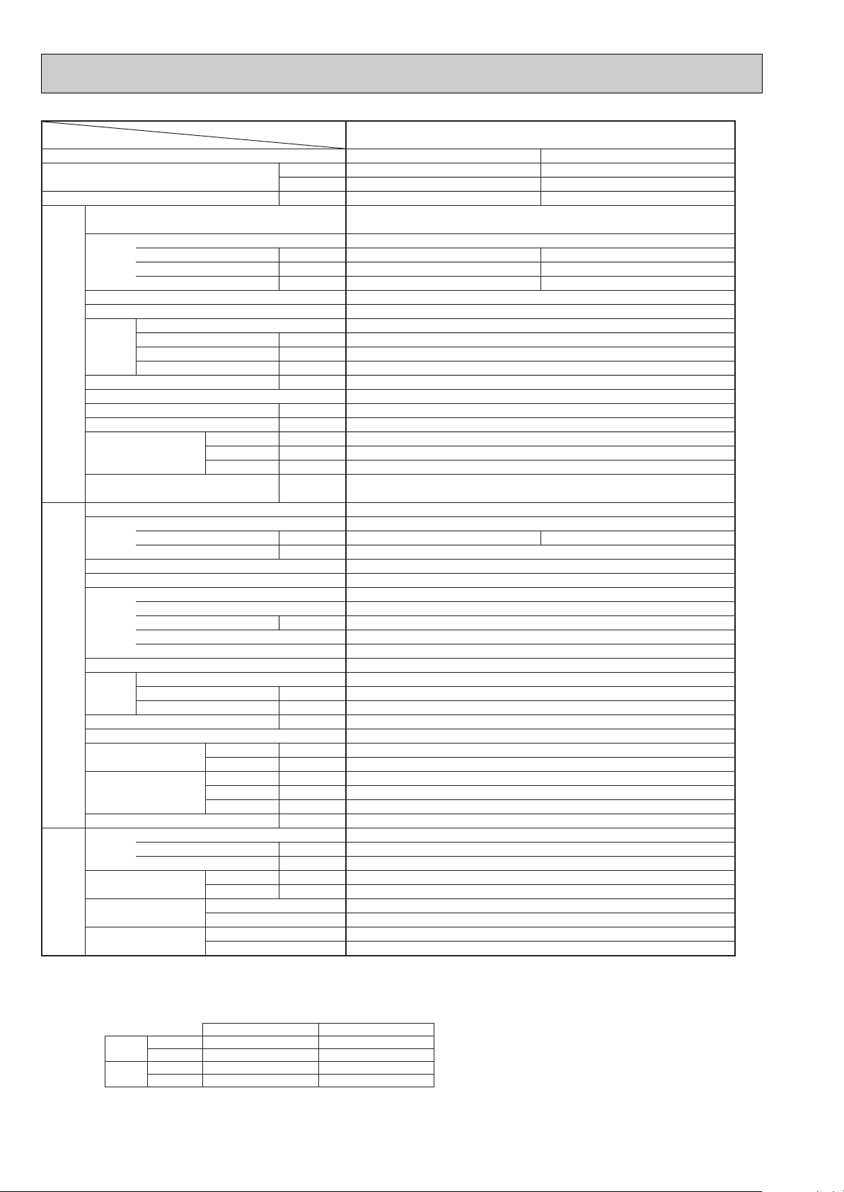
Service Ref.
Item
Function
Capacity
Btu/h
W
Total input k W
Service Ref.
Power supply (phase, cycle,voltage)
Input k W
Running current A
Starting current A
External finish (Panel)
Heat exchanger
Fan
Fan (drive) o No.
Fan motor output kW
Airflow (Lo-Mi2-Mi1-Hi)
K / min (CFM)
External static pressure Pa (mmAq)
Booster heater kW
Operation control & Thermostat
Sound level (Lo-Mi2-Mi1-Hi) dB
Unit drain pipe I.D. mm (in.)
Dimensions
Indoor unit
W mm (in.)
D mm (in.)
H mm (in.)
Weight
kg (lbs.)
Service Ref.
Power supply (phase, cycle, voltage)
Running current A
Starting current A
External finish
Refrigerant control
Compressor
Model
Motor output kW
Starter type
Protection devices
Heat exchanger
Fan (drive) o No.
Fan Fan motor output kW
Airflow
K / min (CFM)
Crankcase heater W
Defrost method
Sound level
Dimensions
Cooling dB
Heating dB
W mm (in.)
D mm (in.)
H mm (in.)
Outdoor unitRefrigerant piping
Weight kg (lbs.)
Refrigerant
Charge kg (lbs.)
Oil (Model) L
Pipe size O.D.
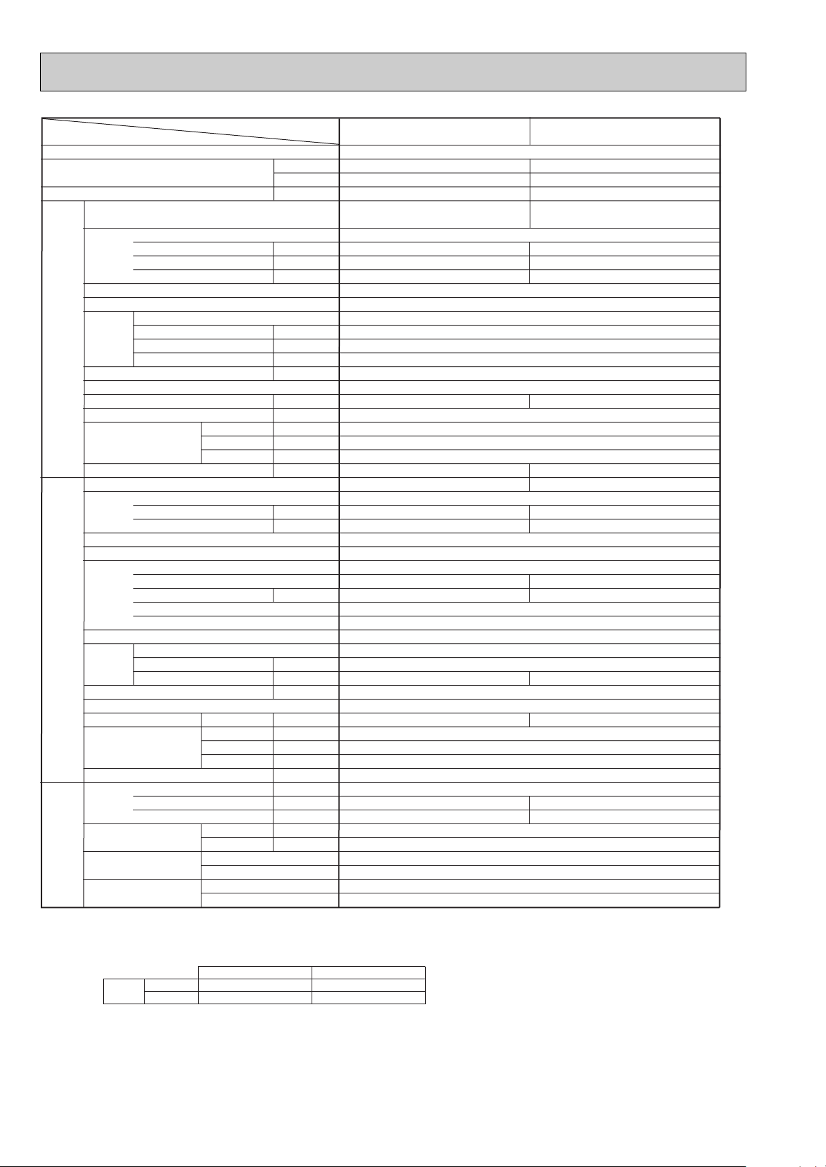
PLA-P6AA.UK
Cooling Heating
48,000 57,300
14,300 16,800
6.70 6.77
PLA-P6AA.UK
Single phase, 50Hz, 220-230-240V (4wires)
0.34 0.34
1.64 1.64
2.0 2.0
Munsell 0.70Y 8.59/0.97
Plate fin coil
Turbo fan (direct) o 1
0.120
22-25-28-30 (775-880-990-1,060)
0 (direct blow)
—
Remote controller & built-in
37-40-43-45
32 (1-1/4)
UNIT : 840 (33-1/16) PANEL : 950 (37-3/8)
UNIT : 840 (33-1/16) PANEL : 950 (37-3/8)
UNIT : 298 (11-3/4) PANEL : 30 (1-3/16)
UNIT : 32 (71) PANEL : 5 (11)
PUH-P6YGA
3 phase, 50Hz, 380-400-415V (4wires)
10.17 10.28
84
Munsell 5Y 8/1
Linear expansion valve
Hermetic
HE101YAA
5.1
Line start
Internal thermostat, Anit-phase protector, Thermal relay, HP switch, LP switch, Discharge thermo.
Plate fin coil
Propeller (direct) o 2
0.075+0.075
100 (3,530)
38
Reverse cycle
55
57
1,050 (41-5/16)
330+20(13+3/4)
1,260 (49-5/8)
122 (269)
R407C
5.8 (12.8)
2.0 (MEL32)
9.52 (3/8)
19.05 (3/4)
Flared
Flared
Max. 50m
Max. 50m
Liquid mm (in.)
Gas mm (in.)
Connection method
Indoor side
Outdoor side
Between the indoor &
outdoor units
Height difference
Piping length
NOTE: 1. Rating conditions (ISO T1)
Cooling : Indoor: D.B. 27: (80˚F) W.B. 19: (66˚F) Outdoor: D.B. 35: (95˚F) W.B. 24: (75˚F)
Heating : Indoor: D.B. 20: (68˚F) Outdoor: D.B. 7: (45˚F) W.B. 6: (43˚F)
Refrigerant piping length (one way) : 5m (16ft.)
2. Guaranteed operating range
Indoor Outdoor
Cooling
Upper limit D.B. 35:, W.B. 22.5: D.B. 46:
Lower limit D.B. 19 :, W.B. 15: D.B. -5:
Heating
Upper limit D.B. 28: D.B. 24 :, W.B. 18:
Lower limit D.B. 17: D.B. -11:, W.B. -12:
3. Above data based on indicated voltage
Indoor unit Single phase 240V 50Hz
Outdoor unit 3 phase 415V 50Hz
14
Page 15
Item
Function
Capacity
Total input
Service Ref.
Power supply (phase, cycle,voltage)
Input k W
Running current A
Starting current A
External finish (Panel)
Heat exchanger
Fan (drive) o No.
Fan
Indoor unit
Booster heater kW
Fan motor output kW
Airflow (Lo-Mi2-Mi1-Hi)
External static pressure Pa (mmAq)
Operation control & Thermostat
Sound level (Lo-Mi2-Mi1-Hi) dB
Unit drain pipe I.D. mm (in.)
Dimensions
Weight
Service Ref.
Power supply (phase, cycle, voltage)
Running current A
Starting current A
External finish
Refrigerant control
Compressor
Model
Motor output kW
Starter type
Protection devices
Heat exchanger
Outdoor unitRefrigerant piping
Fan Fan motor output kW
Fan (drive) o No.
Airflow K
Crankcase heater W
Defrost method
Sound level
Dimensions
Weight kg (lbs.)
Refrigerant
Charge kg (lbs.)
Oil (Model) L
Pipe size O.D.
Connection method
Between the indoor &
outdoor units
NOTE: 1. Rating conditions (ISO T1)
Cooling Indoor : D.B. 27: (80˚F) W.B. 19: (66˚F) Outdoor : D.B. 35: (95˚F) W.B. 24: (75˚F)
Heating Indoor: D.B. 20: (68˚F) Outdoor : D.B. 7: (45˚F) W.B. 6: (43˚F)
Refrigerant piping length (one way) : 5m (16ft.)
2. Guaranteed operating range
Cooling
Heating
Upper limit
Lower limit
Upper limit
Lower limit
D.B. 35˚C, W.B. 22.5˚C
D.B. 19˚C, W.B. 15˚C D.B. -5˚C
D.B. 28˚C
D.B. 17˚C
Service Ref.
Btu/h
W
kW
K / min (CFM)
W mm (in.)
D mm (in.)
H mm (in.)
kg (lbs.)
/ min (CFM)
Cooling dB
Heating dB
W mm (in.)
D mm (in.)
H mm (in.)
Liquid mm (in.)
Gas mm (in.)
Indoor side
Outdoor side
Height difference
Piping length
Indoor Outdoor
D.B. 46˚C
D.B. 24˚C, W.B. 18˚C
D.B. -11˚C, W.B. -12˚C
PLA-P3AA.UK / PLA-P3AA
1.UK
Cooling Heating
26,600 31,700
7,800 9,300
3.44 3.50
PLA-P3AA.UK / PLA-P3AA1.UK
Single phase, 50Hz, 220-230-240V
0.17 0.17
0.81 0.81
1.0 1.0
Munsell 0.70Y 8.59/0.97
Plate fin coil
Turbo fan (direct) o 1
0.070
15-16-18-20 (530-565-635-705)
0 (direct blow)
—
Remote controller & built-in
28-30-32-34
32 (1-1/4)
UNIT : 840 (33-1/16) PANEL : 950 (37-3/8)
UNIT : 840 (33-1/16) PANEL : 950 (37-3/8)
UNIT : 258 (10-1/2) PANEL : 30 (1-3/16)
UNIT : 24 (53)
PANEL: 5 (11)
PUH-P3VGAA.UK / PUH-P3YGAA.UK
Single phase, 50Hz, 220-230-240V / 3 phase, 50Hz, 380-400-415V (4wires)
14.81/5.29 15.76/5.63
93/47
Munsell 5Y 7/1
Linear expansion valve
Hermetic
NE52VNJMT / NE52YDKMT
2.5
Line start
Internal thermostat, HP switch, Discharge thermo. / Thermal relay , HP switch, Discharge thermo.
Plate fin coil
Propeller (direct) o 1
0.070
50 (1,770)
38
Reverse cycle
49
51
900 (35-7/16)
330+20 (13+3/4)
855 (33-5/8)
82 (181)
R407C
3.3 (7.3)
1.3 (Ester) MEL56
9.52 (3/8)
15.88 (5/8)
Flared
Flared
Max. 50m
Max. 50m
3. Above data based on indicated voltage
Indoor unit Single phase 240V 50Hz
Outdoor unit Single phase 240V 50Hz / 3 phase 415V 50Hz
15
Page 16
Service Ref.
Item
Function
Capacity
Btu/h
W
Total input k W
Service Ref.
Power supply (phase, cycle,voltage)
Input k W
Running current A
Starting current A
External finish (Panel)
Heat exchanger
Fan
Fan (drive) o No.
Fan motor output kW
Airflow (Lo-Mi2-Mi1-Hi)
K / min (CFM)
External static pressure Pa (mmAq)
Booster heater kW
Operation control & Thermostat
Sound level (Lo-Mi2-Mi1-Hi) dB
Unit drain pipe I.D. mm (in.)
Dimensions
Indoor unit
W mm (in.)
D mm (in.)
H mm (in.)
Weight
kg (lbs.)
Service Ref.
Power supply (phase, cycle, voltage)
Running current A
Starting current A
External finish
Refrigerant control
Compressor
Model
Motor output kW
Starter type
Protection devices
Heat exchanger
Fan (drive) o No.
Fan Fan motor output kW
Airflow
K / min (CFM)
Crankcase heater W
Defrost method
Sound level
Dimensions
Cooling dB
Heating dB
W mm (in.)
D mm (in.)
H mm (in.)
Outdoor unitRefrigerant piping
Weight kg (lbs.)
Refrigerant
Charge kg (lbs.)
Oil (Model) L
Pipe size O.D.
PLA-P4AA.UK / PLA-P4AA1.UK
Cooling Heating
33,100 36,200
9,700 10,600
3.69 3.93
PLA-P4AA.UK / PLA-P4AA1.UK
Single phase, 50Hz, 220-230-240V
0.26 0.26
1.25 1.25
2.0 2.0
Munsell 0.70Y 8.59/0.97
Plate fin coil
Turbo fan (direct) o 1
0.120
20-23-26-28 (705-810-920-990)
0 (direct blow)
—
Remote controller & built-in
33-36-39-41
32 (1-1/4)
UNIT : 840 (33-1/16) PANEL : 950 (37-3/8)
UNIT : 840 (33-1/16) PANEL : 950 (37-3/8)
UNIT : 298 (11-3/4) PANEL : 30 (1-3/16)
UNIT : 30 (66) PANEL : 5 (11)
PUH-P4VGAA.UK / PUH-P4YGAA.UK
Single phase, 50Hz, 220-230-240V/ 3 phase, 50Hz, 380-400-415V (4wires)
15.71/ 5.55 16.58/ 5.86
99/49
Munsell 5Y 7/1
Linear expansion valve
Hermetic
NE56VNJMT/ NE56YDKMT
2.7
Line start
Intemal thermostat,HP switch, Discharge thermo. / Thermal relay, HP swich, Dischage thermo.
Plate fin coil
Propeller (direct) o 2
0.070+0.070
85 (3,000)
38
Reverse cycle
51
53
900 (35-7/16)
330+20 (13+3/4)
1,260 (49-5/8)
96 (212)
R407C
4.0 (8.8)
1.3 (MEL56)
9.52 (3/8)
19.05 (3/4)
Flared
Flared
Max. 50m
Max. 50m
Liquid mm (in.)
Gas mm (in.)
Connection method
Indoor side
Outdoor side
Between the indoor &
outdoor units
Height difference
Piping length
NOTE: 1. Rating conditions (ISO T1)
Cooling Indoor : D.B. 27: (80˚F) W.B. 19: (66˚F) Outdoor : D.B. 35: (95˚F) W.B. 24: (75˚F)
Heating Indoor: D.B. 20: (68˚F) Outdoor : D.B. 7: (45˚F) W.B. 6: (43˚F)
Refrigerant piping length (one way) : 5m (16ft.)
2. Guaranteed operating range
3. Above data based on indicated voltage
Indoor unit Single phase 240V 50Hz
Outdoor unit 3 phase 415V 50Hz
Indoor Outdoor
Cooling
Upper limit
D.B. 35˚C, W.B. 22.5˚C
D.B. 46˚C
Lower limit
D.B. 19˚C, W.B. 15˚C D.B. -5˚C
Heating
Upper limit
D.B. 28˚C
D.B. 24˚C, W.B. 18˚C
Lower limit
D.B. 17˚C
D.B. -11˚C, W.B. -12˚C
16
Page 17
Item
Service Ref.
Function
Capacity
Btu/h
Total input k W
Service Ref.
Power supply (phase, cycle,voltage)
Input k W
Running current A
Starting current A
External finish (Panel)
Heat exchanger
Fan (drive) o No.
Fan
Indoor unit
Booster heater kW
Fan motor output kW
Airflow (Lo-Mi2-Mi1-Hi)
K / min (CFM)
External static pressure Pa (mmAq)
Operation control & Thermostat
Sound level (Lo-Mi2-Mi1-Hi) dB
Unit drain pipe I.D. mm (in.)
W mm (in.)
Dimensions
D mm (in.)
H mm (in.)
Weight
kg (lbs.)
Service Ref.
Power supply (phase, cycle, voltage)
Running current A
Starting current A
External finish
Refrigerant control
Compressor
Model
Motor output kW
Starter type
Protection devices
Heat exchanger
Outdoor unitRefrigerant piping
Fan Fan motor output kW
Fan (drive) o No.
Airflow
K / min (CFM)
Crankcase heater W
Defrost method
Sound level
Cooling dB
Heating dB
W mm (in.)
Dimensions
D mm (in.)
H mm (in.)
Weight kg (lbs.)
Refrigerant
Charge kg (lbs.)
Oil (Model) L
Pipe size O.D.
Connection method
Between the indoor &
outdoor units
NOTE: 1. Rating conditions (ISO T1)
Cooling : Indoor: D.B. 27: (80˚F) W.B. 19: (66˚F) Outdoor: D.B. 35: (95˚F) W.B. 24: (75˚F)
Heating : Indoor: D.B. 20: (68˚F) Outdoor: D.B. 7: (45˚F) W.B. 6: (43˚F)
Refrigerant piping length (one way) : 5m (16ft.)
2. Guaranteed operating range
Upper limit D.B. 35:, W.B. 22.5: D.B. 46:
Cooling
Lower limit D.B. 19 :, W.B. 15: D.B. -5:
Upper limit D.B. 28
Heating
Lower limit D.B. 17: D.B. -11:, W.B. -12:
Liquid mm (in.)
Gas mm (in.)
Indoor side
Outdoor side
Height difference
Piping length
Indoor Outdoor
:
W
D.B. 24 :, W.B. 18:
PLA-P5AA.UK / PLA-P5AA1.UK
Cooling Heating
43,700 50,800
12,800 14,900
5.00 5.34
PLA-P5AA.UK / PLA-P5AA1.UK
Single phase, 50Hz, 220-230-240V
0.30 0.30
1.43 1.43
2.0 2.0
Munsell 0.70Y 8.59/0.97
Plate fin coil
Turbo fan (direct) o 1
0.120
22-25-28-30 (775-880-990-1,060)
0 (direct blow)
—
Remote controller & built-in
35-38-41-43
32 (1-1/4)
UNIT : 840 (33-1/16) PANEL : 950 (37-3/8)
UNIT : 840 (33-1/16) PANEL : 950 (37-3/8)
UNIT : 298 (11-3/4) PANEL : 30 (1-3/16)
UNIT : 30 (66) PANEL : 5 (11)
PUH-P5YGAA.UK
3 phase, 50Hz, 380-400-415V (4wires)
7.60 8.15
65.5
Munsell 5Y 7/1
Linear expansion valve
Hermetic
ZR61KCE-TFD
3.5
Line start
Internal thermostat, Thermal relay, HP swich, Discharge thermo.
Plate fin coil
Propeller (direct) o 2
0.070+0.070
95 (3,360)
38
Reverse cycle
55
56
1,050 (41-5/16)
330+20 (13+3/4)
1,260 (49-5/8)
122 (269)
R407C
4.6 (10.1)
1.690 (Ester) MMMA-POE
9.52 (3/8)
19.05 (3/4)
Flared
Flared
Max. 50m
Max. 50m
3. Above data based on indicated voltage
Indoor unit Single phase 240V 50Hz
Outdoor unit 3 phase 415V 50Hz
17
Page 18
Service Ref.
Item
Function
Capacity
Btu/h
W
Total input k W
Service Ref.
Power supply (phase, cycle,voltage)
Input k W
Running current A
Starting current A
External finish (Panel)
Heat exchanger
Fan
Fan (drive) o No.
Fan motor output kW
Airflow (Lo-Mi2-Mi1-Hi)
K / min (CFM)
External static pressure Pa (mmAq)
Booster heater kW
Operation control & Thermostat
Sound level (Lo-Mi2-Mi1-Hi) dB
Unit drain pipe I.D. mm (in.)
Dimensions
Indoor unit
W mm (in.)
D mm (in.)
H mm (in.)
Weight
kg (lbs.)
Service Ref.
Power supply (phase, cycle, voltage)
Running current A
Starting current A
External finish
Refrigerant control
Compressor
Model
Motor output kW
Starter type
Protection devices
Heat exchanger
Fan (drive) o No.
Fan Fan motor output kW
Airflow
K / min (CFM)
Crankcase heater W
Defrost method
Sound level
Dimensions
Cooling dB
Heating dB
W mm (in.)
D mm (in.)
H mm (in.)
Outdoor unitRefrigerant piping
Weight kg (lbs.)
Refrigerant
Charge kg (lbs.)
Oil (Model) L
Pipe size O.D.
PLA-P6AA.UK / PLA-P6AA1.UK
Cooling Heating
48,000 58,300
14,300 17,100
5.94 6.36
PLA-P6AA.UK / PLA-P6AA1.UK
Single phase, 50Hz, 220-230-240V
0.34 0.34
1.64 1.64
2.0 2.0
Munsell 0.70Y 8.59/0.97
Plate fin coil
Turbo fan (direct) o 1
0.120
22-25-28-30 (775-880-990-1,060)
0 (direct blow)
Remote controller & built-in
37-40-43-45
32 (1-1/4)
UNIT : 840 (33-1/16) PANEL : 950 (37-3/8)
UNIT : 840 (33-1/16) PANEL : 950 (37-3/8)
UNIT : 298 (11-3/4) PANEL : 30 (1-3/16)
UNIT : 32 (71) PANEL : 5 (11)
PUH-P6YGAA.UK
3 phase, 50Hz, 380-400-415V (4wires)
9.03 9.56
74
Munsell 5Y 7/1
Linear expansion valve
Hermetic
ZR72KCE-TFD
4.2
Line start
Internal thermostat, Thermal relay, HP switch, Discharge thermo.
Plate fin coil
Propeller (direct) o 2
0.070+0.070
100 (3,530)
38
Reverse cycle
57
58
1,050 (41-5/16)
330+20 (13+3/4)
1,260 (49-5/8)
122 (269)
R407C
4.9 (10.8)
1.774 (Ester) MMMA-POE
9.52 (3/8)
19.05 (3/4)
Flared
Flared
Max. 50m
Max. 50m
Liquid mm (in.)
Gas mm (in.)
Connection method
Indoor side
Outdoor side
Between the indoor &
outdoor units
Height difference
Piping length
NOTE: 1. Rating conditions (ISO T1)
Cooling : Indoor: D.B. 27: (80˚F) W.B. 19: (66˚F) Outdoor: D.B. 35: (95˚F) W.B. 24: (75˚F)
Heating : Indoor: D.B. 20: (68˚F) Outdoor: D.B. 7: (45˚F) W.B. 6: (43˚F)
Refrigerant piping length (one way) : 5m (16ft.)
2. Guaranteed operating range
Indoor Outdoor
Cooling
Upper limit D.B. 35:, W.B. 22.5: D.B. 46:
Lower limit D.B. 19 :, W.B. 15: D.B. -5:
Heating
Upper limit D.B. 28
:
D.B. 24 :, W.B. 18:
Lower limit D.B. 17: D.B. -11:, W.B. -12:
3. Above data based on indicated voltage
Indoor unit Single phase 240V 50Hz
Outdoor unit 3 phase 415V 50Hz
—
18
Page 19
2.Cooling only type
Service Ref.
Item
Function
Capacity
Total input kW
Service Ref.
Power supply (phase, cycle,voltage)
Input kW
Running current A
Starting current A
External finish (Panel)
Heat exchanger
Fan (drive) o No.
Fan
Indoor unit
Booster heater kW
Fan motor output kW
Airflow (Lo-Mi2-Mi1-Hi)
External static pressure Pa (mmAq)
Operation control & Thermostat
Sound level (Lo-Mi2-Mi1-Hi) dB
Unit drain pipe I.D. mm (in.)
W mm (in.)
Dimensions
D mm (in.)
H mm (in.)
Weight kg (lbs.)
Service Ref.
Power supply (phase, cycle, voltage)
Running current A
Starting current A
External finish
Refrigerant control
Compressor
Model
Motor output kW
Starter type
Protection devices
Heat exchanger
Outdoor unitRefrigerant piping
Fan (drive) o No.
Fan Fan motor output kW
Airflow
Crankcase heater W
Defrost method
Sound level
Cooling dB
W mm (in.)
Dimensions
D mm (in.)
H mm (in.)
Weight kg (lbs.)
Refrigerant
Charge kg (lbs.)
Oil (Model) L
Pipe size O.D.
Connection method
Between the indoor &
outdoor units
NOTE: 1. Rating conditions (ISO T1)
Cooling : Indoor: D.B. 27: (80˚F) W.B. 19: (66˚F) Outdoor : D.B. 35: (95˚F) W.B. 24: (75˚F)
Refrigerant piping length (one way) : 5m (16ft.)
2. Guaranteed operating range
Cooling
3. Above data based on indicated voltage
Indoor unit Single phase 240V 50Hz
Outdoor unit Single phase 240V 50Hz, 3 phase 415V 50Hz
Upper limit D.B. 35˚C, W.B. 22.5˚C D.B. 46˚C
Lower limit D.B. 19˚C, W.B. 15˚C D.B. -5˚C
Liquid mm (in.)
Gas mm (in.)
Indoor side
Outdoor side
Height difference
Piping length
Indoor Outdoor
Btu/h
K / min (CFM)
K / min (CFM)
PLA-P3AA.UK PLA-P4AA.UK
Cooling
26,600 33,100
W
7,800 9,700
3.51 3.62
PLA-P3AA.UK PLA-P4AA.UK
Single phase, 50Hz, 220-230-240V
0.17 0.26
0.81 1.25
1.0 2.0
Munsell 0.70Y 8.59/0.97
Plate fin coil
Turbo fan (direct) o 1
0.070 0.120
15-16-18-20 (530-565-635-705) 20-23-26-28 (705-810-920-990)
0 (direct blow)
—
Remote controller & built-in
28-30-32-34 33-36-39-41
32 (1-1/4)
UNIT : 840
UNIT : 840
(33-1/16),
PANEL : 950 (37-3/8) UNIT : 840
(33-1/16),
PANEL : 950 (37-3/8) UNIT : 840
(33-1/16),
PANEL : 950 (37-3/8)
(33-1/16),
PANEL : 950 (37-3/8)
UNIT : 258 (10-1/2), PANEL : 30 (1-3/16) UNIT : 298 (11-3/4), PANEL : 30 (1-3/16)
UNIT : 26 (57), PANEL : 5 (11) UNIT : 29 (64), PANEL : 5 (11)
PU-P3VGA / PU-P3YGA PU-P4YGA
w1
3 phase, 50Hz, 380-400-415V (4wires)
14.64 / 5.46 5.49
93 / 41 45
Munsell 5Y 8/1
Linear expansion valve
Hermetic
NE52VNJM / NE52YDJM NE56YDJM
2.5 2.7
Line start
Internal thermostat, HP switch, Discharge thermo. /
Thermal rely, Discharge thermo, HP switch, Anti-phase protector.
Anti-phase protector, Thermal relay,
Discharge thermo, HP switch
Plate fin coil
Propeller (direct) o 1 Propeller (direct) o 2
0.070 0.070+0.070
50 (1,770) 85 (3,000)
38
—
49 51
900 (35-7/16)
330+20 (13+3/4)
855 (33-5/8) 1,260 (49-5/8)
82 (181) 96 (212)
R407C
3.7 (8.2) 4.0 (8.8)
1.6 (MEL56)
9.52 (3/8)
15.88 (5/8) 19.05 (3/4)
Flared
Flared
Max. 50m
Max. 50m
w1.Single phase, 50Hz, 220-230-240V / 3 phase, 50Hz, 380-400-415V (4wires)
19
Page 20
Weight kg (lbs.)
Service Ref.
Power supply (phase, cycle, voltage)
Running current A
Starting current A
External finish
Refrigerant control
Compressor
Model
Motor output kW
Starter type
Protection devices
Heat exchanger
Fan (drive) o No.
Fan Fan motor output kW
Airflow
K / min (CFM)
Crankcase heater W
Defrost method
Sound level
Service Ref.
Item
Function
Capacity
Btu/h
W
Total input kW
Service Ref.
Power supply (phase, cycle,voltage)
Input kW
Running current A
Starting current A
External finish (Panel)
Heat exchanger
Fan
Fan (drive) o No.
Fan motor output kW
Airflow (Lo-Mi2-Mi1-Hi)
K / min (CFM)
External static pressure Pa (mmAq)
Booster heater kW
Operation control & Thermostat
Sound level (Lo-Mi2-Mi1-Hi) dB
Unit drain pipe I.D. mm (in.)
Dimensions
Indoor unit
W mm (in.)
D mm (in.)
H mm (in.)
Dimensions
Outdoor unitRefrigerant piping
Weight kg (lbs.)
Refrigerant
Charge kg (lbs.)
Oil (Model) L
Pipe size O.D.
PLA-P5AA.UK PLA-P6AA.UK
Cooling
43,700 48,000
12,800 14,300
5.55 6.70
PLA-P5AA.UK PLA-P6AA.UK
Single phase, 50Hz, 220-230-240V
0.30 0.34
1.43 1.64
2.0 2.0
Munsell 0.70Y 8.59/0.97
Plate fin coil
Turbo fan (direct) o 1
0.120
22-25-28-30 (775-880-990-1,060) 22-25-28-30 (775-880-990-1,060)
0 (direct blow)
—
Remote controller & built-in
35-38-41-43 37-40-43-45
32 (1-1/4)
UNIT : 840 (33-1/16), PANEL : 950 (37-3/8)
UNIT : 840 (33-1/16), PANEL : 950 (37-3/8)
UNIT : 298 (11-3/4), PANEL : 30 (1-3/16)
UNIT : 30 (66), PANEL : 5 (11)
PU-P5YGA PU-P6YGA
3 phase, 50Hz, 380-400-415V (4wires)
8.39 10.17
79 84
Munsell 5Y 8/1
Linear expansion valve
Hermetic
HE86YAA HE101YAA
4.3 5.1
Line start
Internal thermostat, Anti-phase protector, Thermal relay, HP switch, LP switch, Discharge thermo.
Plate fin coil
Propeller (direct) o 2
0.075+0.075
95 (3,360) 100 (3,530)
38
—
53 57
1,050 (41-5/16)
330+20 (13+3/4)
1,260 (49-5/8)
122 (269)
R407C
5.8 (12.8)
2.0 (MEL32)
9.52 (3/8)
19.05 (3/4)
Flared
Flared
Max. 50m
Max. 50m
Liquid mm (in.)
Gas mm (in.)
Connection method
Indoor side
Outdoor side
NOTE: 1. Rating conditions (ISO T1)
Cooling : Indoor : D.B. 27: (80˚F) W.B. 19: (66˚F) Outdoor: D.B. 35: (95˚F) W.B. 24: (75˚F)
Refrigerant piping length (one way) : 5m (16ft.)
2. Guaranteed operating range
Indoor Outdoor
Cooling
Upper limit D.B. 35˚C, W.B. 22.5˚C D.B. 46˚C
Lower limit D.B. 19˚C, W.B. 15˚C D.B. -5˚C
3. Above data based on indicated voltage
Indoor unit Single phase 240V 50Hz
Outdoor unit 3 phase 415V 50Hz
Between the indoor &
outdoor units
Height difference
Piping length
Cooling dB
W mm (in.)
D mm (in.)
H mm (in.)
20
Page 21
Service Ref.
Item
Function
Capacity
Btu/h
Total input kW
Service Ref.
Power supply (phase, cycle,voltage)
Input kW
Running current A
Starting current A
External finish (Panel)
Heat exchanger
Fan (drive) o No.
Fan
Indoor unit
Booster heater kW
Fan motor output kW
Airflow (Lo-Mi2-Mi1-Hi)
K / min (CFM)
External static pressure Pa (mmAq)
Operation control & Thermostat
Sound level (Lo-Mi2-Mi1-Hi) dB
Unit drain pipe I.D. mm (in.)
W mm (in.)
Dimensions
D mm (in.)
H mm (in.)
Weight kg (lbs.)
Service Ref.
Power supply (phase, cycle, voltage)
Running current A
Starting current A
External finish
Refrigerant control
Compressor
Model
Motor output kW
Starter type
Protection devices
Heat exchanger
Outdoor unitRefrigerant piping
Fan (drive) o No.
Fan Fan motor output kW
Airflow
K / min (CFM)
Crankcase heater W
Defrost method
Sound level
Cooling dB
W mm (in.)
Dimensions
D mm (in.)
H mm (in.)
Weight kg (lbs.)
Refrigerant
Charge kg (lbs.)
Oil (Model) L
Pipe size O.D.
Connection method
Between the indoor &
outdoor units
NOTE: 1. Rating conditions (ISO T1)
Cooling : Indoor: D.B. 27: (80˚F) W.B. 19: (66˚F) Outdoor : D.B. 35: (95˚F) W.B. 24: (75˚F)
Refrigerant piping length (one way) : 5m (16ft.)
2. Guaranteed operating range
Cooling
3. Above data based on indicated voltage
Indoor unit Single phase 240V 50Hz
Outdoor unit Single phase 240V 50Hz, 3 phase 415V 50Hz
Upper limit D.B. 35˚C, W.B. 22.5˚C D.B. 46˚C
Lower limit D.B. 19˚C, W.B. 15˚C D.B. -5˚C
Liquid mm (in.)
Gas mm (in.)
Indoor side
Outdoor side
Height difference
Piping length
Indoor Outdoor
PLA-P3AA.UK
PLA-P3AA1.UK
PLA-P4AA.UK
PLA-P4AA1.UK
Cooling
26,600 33,100
W
7,800 9,700
3.44 3.69
PLA-P3AA.UK PLA-P4AA.UK
PLA-P3AA
1.UK PLA-P4AA1.UK
Single phase, 50Hz, 220-230-240V
0.17 0.26
0.81 1.25
1.0 2.0
Munsell 0.70Y 8.59/0.97
Plate fin coil
Turbo fan (direct) o 1
0.070 0.120
15-16-18-20 (530-565-635-705) 20-23-26-28 (705-810-920-990)
0 (direct blow)
—
Remote controller & built-in
28-30-32-34 33-36-39-41
32 (1-1/4)
UNIT : 840
UNIT : 840
(33-1/16),
PANEL : 950 (37-3/8) UNIT : 840
(33-1/16),
PANEL : 950 (37-3/8) UNIT : 840
(33-1/16),
PANEL : 950 (37-3/8)
(33-1/16),
PANEL : 950 (37-3/8)
UNIT : 258 (10-1/2), PANEL : 30 (1-3/16) UNIT : 298 (11-3/4), PANEL : 30 (1-3/16)
UNIT : 24 (53), PANEL : 5 (11) UNIT : 30 (66), PANEL : 5 (11)
PU-P3VGAA.UK / PU-P3YGAA.UK PU-P4VGAA.UK / PU-P4YGAA.UK
Single phase, 50Hz, 220-230-240V/ 3 phase, 50Hz, 380-400-415V (4wires)
14.81 / 5.29 15.71 / 5.55
93 / 47 99 / 49
Munsell 5Y 7/1
Linear expansion valve
Hermetic
NE52VNJMT / NE52YDKMT NE56VNJMT / NE56YDKMT
2.5 2.7
Line start
Internal thermostat, HP switch, Discharge thermo. /
Thermal relay, HP switch, Discharge thermo.
Plate fin coil
Propeller (direct) o 1 Propeller (direct) o 2
0.070 0.070+0.070
50 (1,770) 85 (3,000)
38
—
49 51
900 (35-7/16)
330+20 (13+3/4)
855 (33-5/8) 1,260 (49-5/8)
82 (181) 96 (212)
R407C
3.3 (7.3) 4.0 (8.8)
1.3 (Ester)MEL56
9.52 (3/8)
15.88 (5/8) 19.05 (3/4)
Flared
Flared
Max. 50m
Max. 50m
21
Page 22
Weight kg (lbs.)
Service Ref.
Power supply (phase, cycle, voltage)
Running current A
Starting current A
External finish
Refrigerant control
Compressor
Model
Motor output kW
Starter type
Protection devices
Heat exchanger
Fan (drive) o No.
Fan Fan motor output kW
Airflow
K / min (CFM)
Crankcase heater W
Defrost method
Sound level
Service Ref.
Item
Function
Capacity
Btu/h
W
Total input kW
Service Ref.
Power supply (phase, cycle,voltage)
Input kW
Running current A
Starting current A
External finish (Panel)
Heat exchanger
Fan
Fan (drive) o No.
Fan motor output kW
Airflow (Lo-Mi2-Mi1-Hi)
K / min (CFM)
External static pressure Pa (mmAq)
Booster heater kW
Operation control & Thermostat
Sound level (Lo-Mi2-Mi1-Hi) dB
Unit drain pipe I.D. mm (in.)
Dimensions
Indoor unit
W mm (in.)
D mm (in.)
H mm (in.)
Dimensions
Outdoor unitRefrigerant piping
Weight kg (lbs.)
Refrigerant
Charge kg (lbs.)
Oil (Model) L
Pipe size O.D.
PLA-P5AA.UK PLA-P6AA.UK
Cooling
43,700 48,000
12,800 14,300
5.00 5.94
PLA-P5AA
1.UK PLA-P6AA1.UK
PLA-P5AA.UK PLA-P6AA.UK
Single phase, 50Hz, 220-230-240V
0.30 0.34
1.43 1.64
2.0 2.0
Munsell 0.70Y 8.59/0.97
Plate fin coil
Turbo fan (direct) o 1
0.120
22-25-28-30 (775-880-990-1,060)
0 (direct blow)
—
Remote controller & built-in
35-38-41-43 37-40-43-45
32 (1-1/4)
UNIT : 840 (33-1/16), PANEL : 950 (37-3/8)
UNIT : 840 (33-1/16), PANEL : 950 (37-3/8)
UNIT : 298 (11-3/4), PANEL : 30 (1-3/16)
UNIT : 30 (66), PANEL : 5 (11) UNIT : 32 (71), PANEL : 5 (11)
PU-P5YGAA.UK PU-P6YGAA.UK
3 phase, 50Hz, 380-400-415V (4wires)
7.60 9.03
65.5 74
Munsell 5Y 7/1
Linear expansion valve
Hermetic
ZR61KCE-TFD ZR72KCE-TFD
3.5 4.2
Line start
Internal thermostat,Thermal relay, HP switch, Discharge thermo.
Plate fin coil
Propeller (direct) o 2
0.070+0.070
95 (3,360) 100 (3,530)
38
—
55 57
1,050 (41-5/16)
330+20 (13+3/4)
1,260 (49-5/8)
122 (269)
R407C
4.6 (10.1)
1.690 (Ester)MMM-POE
4.9 (10.8)
1.774 (Ester)MMM-POE
9.52 (3/8)
19.05 (3/4)
Flared
Flared
Max. 50m
Max. 50m
Liquid mm (in.)
Gas mm (in.)
Connection method
Indoor side
Outdoor side
NOTE: 1. Rating conditions (ISO T1)
Cooling : Indoor : D.B. 27: (80˚F) W.B. 19: (66˚F) Outdoor: D.B. 35: (95˚F) W.B. 24: (75˚F)
Refrigerant piping length (one way) : 5m (16ft.)
2. Guaranteed operating range
Indoor Outdoor
Cooling
Upper limit D.B. 35˚C, W.B. 22.5˚C D.B. 46˚C
Lower limit D.B. 19˚C, W.B. 15˚C D.B. -5˚C
3. Above data based on indicated voltage
Indoor unit Single phase 240V 50Hz
Outdoor unit 3 phase 415V 50Hz
Between the indoor &
outdoor units
Height difference
Piping length
Cooling dB
W mm (in.)
D mm (in.)
H mm (in.)
22
Page 23

6DATA
1.1 COOLING CAPACITY (1)
PLA-P3AA.UK / PU(H)-P3VGA, PU(H)-P3YGA
(240V)
Outdoor intake air DB (:)
20 25 30
CA SHC SHF P.C. CA SHC SHF P.C. CA SHC SHF P.C.
20 16 7,722 4,942 0.64 2.81 7,488 4,792 0.64 2.97 7,254 4,643 0.64 3.14
20 18 8,268 4,299 0.52 2.86 8,034 4,178 0.52 3.02 7,761 4,036 0.52 3.23
20 20 8,892 3,557 0.40 2.95 8,697 3,479 0.40 3.09 8,463 3,385 0.40 3.30
22 16 7,722 5,560 0.72 2.81 7,488 5,391 0.72 2.97 7,254 5,223 0.72 3.14
22 18 8,268 4,961 0.60 2.86 8,034 4,820 0.60 3.02 7,761 4,657 0.60 3.23
22 20 8,892 4,268 0.48 2.95 8,697 4,175 0.48 3.09 8,463 4,062 0.48 3.30
24 16 7,722 6,178 0.80 2.81 7,488 5,990 0.80 2.97 7,254 5,803 0.80 3.14
24 18 8,268 5,622 0.68 2.86 8,034 5,463 0.68 3.02 7,761 5,277 0.68 3.23
24 20 8,892 4,980 0.56 2.95 8,697 4,870 0.56 3.09 8,463 4,739 0.56 3.30
24 22 9,477 4,170 0.44 3.02 9,282 4,084 0.44 3.19 9,048 3,981 0.44 3.40
26 16 7,722 6,795 0.88 2.81 7,488 6,589 0.88 2.97 7,254 6,384 0.88 3.14
26 18 8,268 6,284 0.76 2.86 8,034 6,106 0.76 3.02 7,761 5,898 0.76 3.23
26 20 8,892 5,691 0.64 2.95 8,697 5,566 0.64 3.09 8,463 5,416 0.64 3.30
26 22 9,477 4,928 0.52 3.02 9,282 4,827 0.52 3.19 9,048 4,705 0.52 3.40
28 16 7,722 7,413 0.96 2.81 7,488 7,188 0.96 2.97 7,254 6,964 0.96 3.14
28 18 8,268 6,945 0.84 2.86 8,034 6,749 0.84 3.02 7,761 6,519 0.84 3.23
28 20 8,892 6,402 0.72 2.95 8,697 6,262 0.72 3.09 8,463 6,093 0.72 3.30
28 22 9,477 5,686 0.60 3.02 9,282 5,569 0.60 3.19 9,048 5,429 0.60 3.40
30 16 7,722 7,722 1.00 2.81 7,488 7,488 1.00 2.97 7,254 7,254 1.00 3.14
30 18 8,268 7,607 0.92 2.86 8,034 7,391 0.92 3.02 7,761 7,140 0.92 3.23
30 20 8,892 7,114 0.80 2.95 8,697 6,958 0.80 3.09 8,463 6,770 0.80 3.30
30 22 9,477 6,444 0.68 3.02 9,282 6,312 0.68 3.19 9,048 6,153 0.68 3.40
32 16 7,722 7,722 1.00 2.81 7,488 7,488 1.00 2.97 7,254 7,254 1.00 3.14
32 18 8,268 8,268 1.00 2.86 8,034 8,034 1.00 3.02 7,761 7,761 1.00 3.23
32 20 8,892 7,825 0.88 2.95 8,697 7,653 0.88 3.09 8,463 7,447 0.88 3.30
32 22 9,477 7,203 0.76 3.02 9,282 7,054 0.76 3.19 9,048 6,876 0.76 3.40
34 16 7,722 7,722 1.00 2.81 7,488 7,488 1.00 2.97 7,254 7,254 1.00 3.14
34 18 8,268 8,268 1.00 2.86 8,034 8,034 1.00 3.02 7,761 7,761 1.00 3.23
34 20 8,892 8,536 0.96 2.95 8,697 8,349 0.96 3.09 8,463 8,124 0.96 3.30
34 22 9,477 7,961 0.84 3.02 9,282 7,797 0.84 3.19 9,048 7,600 0.84 3.40
NOTE: CA: Capacity (W) SHC: Sensible heat capacity (W)
P.C.: Power consumption (kW) SHF: Sensible heat factor
Indoor
intake air
WB
(:)
Indoor
intake air
DB
(:)
1. PERFORMANCE DATA
23
Page 24

COOLING CAPACITY (2)
PLA-P3AA.UK / PU(H)-P3VGA, PU(H)-P3YGA
(240V)
Outdoor intake air DB (:)
35 40 45
CA SHC SHF P.C. CA SHC SHF P.C. CA SHC SHF P.C.
20 16 6,942 4,443 0.64 3.37 6,630 4,243 0.64 3.62 6,318 4,044 0.64 3.91
20 18 7,488 3,894 0.52 3.46 7,254 3,772 0.52 3.72 6,786 3,529 0.52 4.00
20 20 8,112 3,245 0.40 3.55 7,800 3,120 0.40 3.79 7,332 2,933 0.40 4.07
22 16 6,942 4,998 0.72 3.37 6,630 4,774 0.72 3.62 6,318 4,549 0.72 3.91
22 18 7,488 4,493 0.60 3.46 7,254 4,352 0.60 3.72 6,786 4,072 0.60 4.00
22 20 8,112 3,894 0.48 3.55 7,800 3,744 0.48 3.79 7,332 3,519 0.48 4.07
24 16 6,942 5,554 0.80 3.37 6,630 5,304 0.80 3.62 6,318 5,054 0.80 3.91
24 18 7,488 5,092 0.68 3.46 7,254 4,933 0.68 3.72 6,786 4,614 0.68 4.00
24 20 8,112 4,543 0.56 3.55 7,800 4,368 0.56 3.79 7,332 4,106 0.56 4.07
24 22 8,736 3,844 0.44 3.62 8,424 3,707 0.44 3.90 7,956 3,501 0.44 4.14
26 16 6,942 6,109 0.88 3.37 6,630 5,834 0.88 3.62 6,318 5,560 0.88 3.91
26 18 7,488 5,691 0.76 3.46 7,254 5,513 0.76 3.72 6,786 5,157 0.76 4.00
26 20 8,112 5,192 0.64 3.55 7,800 4,992 0.64 3.79 7,332 4,692 0.64 4.07
26 22 8,736 4,543 0.52 3.62 8,424 4,380 0.52 3.90 7,956 4,137 0.52 4.14
28 16 6,942 6,664 0.96 3.37 6,630 6,365 0.96 3.62 6,318 6,065 0.96 3.91
28 18 7,488 6,290 0.84 3.46 7,254 6,093 0.84 3.72 6,786 5,700 0.84 4.00
28 20 8,112 5,841 0.72 3.55 7,800 5,616 0.72 3.79 7,332 5,279 0.72 4.07
28 22 8,736 5,242 0.60 3.62 8,424 5,054 0.60 3.90 7,956 4,774 0.60 4.14
30 16 6,942 6,942 1.00 3.37 6,630 6,630 1.00 3.62 6,318 6,318 1.00 3.91
30 18 7,488 6,889 0.92 3.46 7,254 6,674 0.92 3.72 6,786 6,243 0.92 4.00
30 20 8,112 6,490 0.80 3.55 7,800 6,240 0.80 3.79 7,332 5,866 0.80 4.07
30 22 8,736 5,940 0.68 3.62 8,424 5,728 0.68 3.90 7,956 5,410 0.68 4.14
32 16 6,942 6,942 1.00 3.37 6,630 6,630 1.00 3.62 6,318 6,318 1.00 3.91
32 18 7,488 7,488 1.00 3.46 7,254 7,254 1.00 3.72 6,786 6,786 1.00 4.00
32 20 8,112 7,139 0.88 3.55 7,800 6,864 0.88 3.79 7,332 6,452 0.88 4.07
32 22 8,736 6,639 0.76 3.62 8,424 6,402 0.76 3.90 7,956 6,047 0.76 4.14
34 16 6,942 6,942 1.00 3.37 6,630 6,630 1.00 3.62 6,318 6,318 1.00 3.91
34 18 7,488 7,488 1.00 3.46 7,254 7,254 1.00 3.72 6,786 6,786 1.00 4.00
34 20 8,112 7,788 0.96 3.55 7,800 7,488 0.96 3.79 7,332 7,039 0.96 4.07
34 22 8,736 7,338 0.84 3.62 8,424 7,076 0.84 3.90 7,956 6,683 0.84 4.14
NOTE: CA: Capacity (W) SHC: Sensible heat capacity (W)
P.C.: Power consumption (kW) SHF: Sensible heat factor
Indoor
intake air
WB
(:)
Indoor
intake air
DB
(:)
24
Page 25

COOLING CAPACITY (3)
PLA-P4AA.UK / PU(H)-P4YGA
Indoor
intake air
DB
Indoor
intake air
WB
(:)
20 16 9,603 6,530 0.68 2.90 9,312 6,332 0.68 3.06 9,021 6,134 0.68 3.24
20 18 10,282 5,758 0.56 2.95 9,991 5,595 0.56 3.11 9,652 5,405 0.56 3.33
20 20 11,058 4,866 0.44 3.04 10,816 4,759 0.44 3.19 10,525 4,631 0.44 3.40
22 16 9,603 7,298 0.76 2.90 9,312 7,077 0.76 3.06 9,021 6,856 0.76 3.24
22 18 10,282 6,580 0.64 2.95 9,991 6,394 0.64 3.11 9,652 6,177 0.64 3.33
22 20 11,058 5,750 0.52 3.04 10,816 5,624 0.52 3.19 10,525 5,473 0.52 3.40
24 16 9,603 8,067 0.84 2.90 9,312 7,822 0.84 3.06 9,021 7,578 0.84 3.24
24 18 10,282 7,403 0.72 2.95 9,991 7,194 0.72 3.11 9,652 6,949 0.72 3.33
24 20 11,058 6,635 0.60 3.04 10,816 6,489 0.60 3.19 10,525 6,315 0.60 3.40
24 22 11,786 5,657 0.48 3.11 11,543 5,541 0.48 3.29 11,252 5,401 0.48 3.51
26 16 9,603 8,835 0.92 2.90 9,312 8,567 0.92 3.06 9,021 8,299 0.92 3.24
26 18 10,282 8,226 0.80 2.95 9,991 7,993 0.80 3.11 9,652 7,721 0.80 3.33
26 20 11,058 7,519 0.68 3.04 10,816 7,355 0.68 3.19 10,525 7,157 0.68 3.40
26 22 11,786 6,600 0.56 3.11 11,543 6,464 0.56 3.29 11,252 6,301 0.56 3.51
28 16 9,603 9,603 1.00 2.90 9,312 9,312 1.00 3.06 9,021 9,021 1.00 3.24
28 18 10,282 9,048 0.88 2.95 9,991 8,792 0.88 3.11 9,652 8,493 0.88 3.33
28 20 11,058 8,404 0.76 3.04 10,816 8,220 0.76 3.19 10,525 7,999 0.76 3.40
28 22 11,786 7,543 0.64 3.11 11,543 7,388 0.64 3.29 11,252 7,201 0.64 3.51
30 16 9,603 9,603 1.00 2.90 9,312 9,312 1.00 3.06 9,021 9,021 1.00 3.24
30 18 10,282 9,871 0.96 2.95 9,991 9,591 0.96 3.11 9,652 9,265 0.96 3.33
30 20 11,058 9,289 0.84 3.04 10,816 9,085 0.84 3.19 10,525 8,841 0.84 3.40
30 22 11,786 8,486 0.72 3.11 11,543 8,311 0.72 3.29 11,252 8,101 0.72 3.51
32 16 9,603 9,603 1.00 2.90 9,312 9,312 1.00 3.06 9,021 9,021 1.00 3.24
32 18 10,282 10,282 1.00 2.95 9,991 9,991 1.00 3.11 9,652 9,652 1.00 3.33
32 20 11,058 10,173 0.92 3.04 10,816 9,950 0.92 3.19 10,525 9,683 0.92 3.40
32 22 11,786 9,428 0.80 3.11 11,543 9,234 0.80 3.29 11,252 9,002 0.80 3.51
34 16 9,603 9,603 1.00 2.90 9,312 9,312 1.00 3.06 9,021 9,021 1.00 3.24
34 18 10,282 10,282 1.00 2.95 9,991 9,991 1.00 3.11 9,652 9,652 1.00 3.33
34 20 11,058 11,058 1.00 3.04 10,816 10,816 1.00 3.19 10,525 10,525 1.00 3.40
34 22 11,786 10,371 0.88 3.11 11,543 10,158 0.88 3.29 11,252 9,902 0.88 3.51
CA SHC SHF P.C. CA SHC SHF P.C. CA SHC SHF P.C.
(:)
20 25 30
Outdoor intake air DB (:)
(240V)
NOTE: CA: Capacity (W) SHC: Sensible heat capacity (W)
P.C.: Power consumption (kW) SHF: Sensible heat factor
25
Page 26

COOLING CAPACITY (4)
PLA-P4AA.UK / PU(H)-P4YGA
(240V)
Outdoor intake air DB (:)
35 40 45
CA SHC SHF P.C. CA SHC SHF P.C. CA SHC SHF P.C.
20 16 8,633 5,870 0.68 3.48 8,245 5,607 0.68 3.73 7,857 5,343 0.68 4.04
20 18 9,312 5,215 0.56 3.57 9,021 5,052 0.56 3.84 8,439 4,726 0.56 4.13
20 20 10,088 4,439 0.44 3.66 9,700 4,268 0.44 3.91 9,118 4,012 0.44 4.20
22 16 8,633 6,561 0.76 3.48 8,245 6,266 0.76 3.73 7,857 5,971 0.76 4.04
22 18 9,312 5,960 0.64 3.57 9,021 5,773 0.64 3.84 8,439 5,401 0.64 4.13
22 20 10,088 5,246 0.52 3.66 9,700 5,044 0.52 3.91 9,118 4,741 0.52 4.20
24 16 8,633 7,252 0.84 3.48 8,245 6,926 0.84 3.73 7,857 6,600 0.84 4.04
24 18 9,312 6,705 0.72 3.57 9,021 6,495 0.72 3.84 8,439 6,076 0.72 4.13
24 20 10,088 6,053 0.60 3.66 9,700 5,820 0.60 3.91 9,118 5,471 0.60 4.20
24 22 10,864 5,215 0.48 3.73 10,476 5,028 0.48 4.02 9,894 4,749 0.48 4.27
26 16 8,633 7,942 0.92 3.48 8,245 7,585 0.92 3.73 7,857 7,228 0.92 4.04
26 18 9,312 7,450 0.80 3.57 9,021 7,217 0.80 3.84 8,439 6,751 0.80 4.13
26 20 10,088 6,860 0.68 3.66 9,700 6,596 0.68 3.91 9,118 6,200 0.68 4.20
26 22 10,864 6,084 0.56 3.73 10,476 5,867 0.56 4.02 9,894 5,541 0.56 4.27
28 16 8,633 8,633 1.00 3.48 8,245 8,245 1.00 3.73 7,857 7,857 1.00 4.04
28 18 9,312 8,195 0.88 3.57 9,021 7,938 0.88 3.84 8,439 7,426 0.88 4.13
28 20 10,088 7,667 0.76 3.66 9,700 7,372 0.76 3.91 9,118 6,930 0.76 4.20
28 22 10,864 6,953 0.64 3.73 10,476 6,705 0.64 4.02 9,894 6,332 0.64 4.27
30 16 8,633 8,633 1.00 3.48 8,245 8,245 1.00 3.73 7,857 7,857 1.00 4.04
30 18 9,312 8,940 0.96 3.57 9,021 8,660 0.96 3.84 8,439 8,101 0.96 4.13
30 20 10,088 8,474 0.84 3.66 9,700 8,148 0.84 3.91 9,118 7,659 0.84 4.20
30 22 10,864 7,822 0.72 3.73 10,476 7,543 0.72 4.02 9,894 7,124 0.72 4.27
32 16 8,633 8,633 1.00 3.48 8,245 8,245 1.00 3.73 7,857 7,857 1.00 4.04
32 18 9,312 9,312 1.00 3.57 9,021 9,021 1.00 3.84 8,439 8,439 1.00 4.13
32 20 10,088 9,281 0.92 3.66 9,700 8,924 0.92 3.91 9,118 8,389 0.92 4.20
32 22 10,864 8,691 0.80 3.73 10,476 8,381 0.80 4.02 9,894 7,915 0.80 4.27
34 16 8,633 8,633 1.00 3.48 8,245 8,245 1.00 3.73 7,857 7,857 1.00 4.04
34 18 9,312 9,312 1.00 3.57 9,021 9,021 1.00 3.84 8,439 8,439 1.00 4.13
34 20 10,088 10,088 1.00 3.66 9,700 9,700 1.00 3.91 9,118 9,118 1.00 4.20
34 22 10,864 9,560 0.88 3.73 10,476 9,219 0.88 4.02 9,894 8,707 0.88 4.27
NOTE: CA: Capacity (W) SHC: Sensible heat capacity (W)
P.C.: Power consumption (kW) SHF: Sensible heat factor
Indoor
intake air
WB
(:)
Indoor
intake air
DB
(:)
26
Page 27

COOLING CAPACITY (5)
PLA-P5AA.UK / PU(H)-P5YGA
Indoor
intake air
DB
Indoor
intake air
WB
(:)
20 16 12,672 7,857 0.62 4.44 12,288 7,619 0.62 4.69 11,904 7,380 0.62 4.97
20 18 13,568 6,784 0.50 4.52 13,184 6,592 0.50 4.77 12,736 6,368 0.50 5.1 1
20 20 14,592 5,545 0.38 4.66 14,272 5,423 0.38 4.88 13,888 5,277 0.38 5.22
22 16 12,672 8,870 0.70 4.44 12,288 8,602 0.70 4.69 11,904 8,333 0.70 4.97
22 18 13,568 7,869 0.58 4.52 13,184 7,647 0.58 4.77 12,736 7,387 0.58 5.1 1
22 20 14,592 6,712 0.46 4.66 14,272 6,565 0.46 4.88 13,888 6,388 0.46 5.22
24 16 12,672 9,884 0.78 4.44 12,288 9,585 0.78 4.69 11,904 9,285 0.78 4.97
24 18 13,568 8,955 0.66 4.52 13,184 8,701 0.66 4.77 12,736 8,406 0.66 5.1 1
24 20 14,592 7,880 0.54 4.66 14,272 7,707 0.54 4.88 13,888 7,500 0.54 5.22
24 22 15,552 6,532 0.42 4.77 15,232 6,397 0.42 5.05 14,848 6,236 0.42 5.38
26 16 12,672 10,898 0.86 4.44 12,288 10,568 0.86 4.69 11,904 10,237 0.86 4.97
26 18 13,568 10,040 0.74 4.52 13,184 9,756 0.74 4.77 12,736 9,425 0.74 5.11
26 20 14,592 9,047 0.62 4.66 14,272 8,849 0.62 4.88 13,888 8,611 0.62 5.22
26 22 15,552 7,776 0.50 4.77 15,232 7,616 0.50 5.05 14,848 7,424 0.50 5.38
28 16 12,672 11,912 0.94 4.44 12,288 11,551 0.94 4.69 11,904 11,190 0.94 4.97
28 18 13,568 11,126 0.82 4.52 13,184 10,811 0.82 4.77 12,736 10,444 0.82 5.11
28 20 14,592 10,214 0.70 4.66 14,272 9,990 0.70 4.88 13,888 9,722 0.70 5.22
28 22 15,552 9,020 0.58 4.77 15,232 8,835 0.58 5.05 14,848 8,612 0.58 5.38
30 16 12,672 12,672 1.00 4.44 12,288 12,288 1.00 4.69 11,904 11,904 1.00 4.97
30 18 13,568 12,211 0.90 4.52 13,184 11,866 0.90 4.77 12,736 11,462 0.90 5.11
30 20 14,592 11,382 0.78 4.66 14,272 11,132 0.78 4.88 13,888 10,833 0.78 5.22
30 22 15,552 10,264 0.66 4.77 15,232 10,053 0.66 5.05 14,848 9,800 0.66 5.38
32 16 12,672 12,672 1.00 4.44 12,288 12,288 1.00 4.69 11,904 11,904 1.00 4.97
32 18 13,568 13,297 0.98 4.52 13,184 12,920 0.98 4.77 12,736 12,481 0.98 5.11
32 20 14,592 12,549 0.86 4.66 14,272 12,274 0.86 4.88 13,888 11,944 0.86 5.22
32 22 15,552 11,508 0.74 4.77 15,232 11,272 0.74 5.05 14,848 10,988 0.74 5.38
34 16 12,672 12,672 1.00 4.44 12,288 12,288 1.00 4.69 11,904 11,904 1.00 4.97
34 18 13,568 13,568 1.00 4.52 13,184 13,184 1.00 4.77 12,736 12,736 1.00 5.11
34 20 14,592 13,716 0.94 4.66 14,272 13,416 0.94 4.88 13,888 13,055 0.94 5.22
34 22 15,552 12,753 0.82 4.77 15,232 12,490 0.82 5.05 14,848 12,175 0.82 5.38
CA SHC SHF P.C. CA SHC SHF P.C. CA SHC SHF P.C.
(:)
20 25 30
Outdoor intake air DB (:)
(240V)
NOTE: CA: Capacity (W) SHC: Sensible heat capacity (W)
P.C.: Power consumption (kW) SHF: Sensible heat factor
27
Page 28

COOLING CAPACITY (6)
PLA-P5AA.UK / PU(H)-P5YGA
(240V)
Outdoor intake air DB (:)
35 40 45
CA SHC SHF P.C. CA SHC SHF P.C. CA SHC SHF P.C.
20 16 11,392 7,063 0.62 5.33 10,880 6,746 0.62 5.72 10,368 6,428 0.62 6.19
20 18 12,288 6,144 0.50 5.47 11,904 5,952 0.50 5.88 11,136 5,568 0.50 6.33
20 20 13,312 5,059 0.38 5.61 12,800 4,864 0.38 5.99 12,032 4,572 0.38 6.44
22 16 11,392 7,974 0.70 5.33 10,880 7,616 0.70 5.72 10,368 7,258 0.70 6.19
22 18 12,288 7,127 0.58 5.47 11,904 6,904 0.58 5.88 11,136 6,459 0.58 6.33
22 20 13,312 6,124 0.46 5.61 12,800 5,888 0.46 5.99 12,032 5,535 0.46 6.44
24 16 11,392 8,886 0.78 5.33 10,880 8,486 0.78 5.72 10,368 8,087 0.78 6.19
24 18 12,288 8,110 0.66 5.47 11,904 7,857 0.66 5.88 11,136 7,350 0.66 6.33
24 20 13,312 7,188 0.54 5.61 12,800 6,912 0.54 5.99 12,032 6,497 0.54 6.44
24 22 14,336 6,021 0.42 5.72 13,824 5,806 0.42 6.16 13,056 5,484 0.42 6.55
26 16 11,392 9,797 0.86 5.33 10,880 9,357 0.86 5.72 10,368 8,916 0.86 6.19
26 18 12,288 9,093 0.74 5.47 11,904 8,809 0.74 5.88 11,136 8,241 0.74 6.33
26 20 13,312 8,253 0.62 5.61 12,800 7,936 0.62 5.99 12,032 7,460 0.62 6.44
26 22 14,336 7,168 0.50 5.72 13,824 6,912 0.50 6.16 13,056 6,528 0.50 6.55
28 16 11,392 10,708 0.94 5.33 10,880 10,227 0.94 5.72 10,368 9,746 0.94 6.19
28 18 12,288 10,076 0.82 5.47 1 1,904 9,761 0.82 5.88 11,136 9,132 0.82 6.33
28 20 13,312 9,318 0.70 5.61 12,800 8,960 0.70 5.99 12,032 8,422 0.70 6.44
28 22 14,336 8,315 0.58 5.72 13,824 8,018 0.58 6.16 13,056 7,572 0.58 6.55
30 16 11,392 11,392 1.00 5.33 10,880 10,880 1.00 5.72 10,368 10,368 1.00 6.19
30 18 12,288 11,059 0.90 5.47 11,904 10,714 0.90 5.88 11,136 10,022 0.90 6.33
30 20 13,312 10,383 0.78 5.61 12,800 9,984 0.78 5.99 12,032 9,385 0.78 6.44
30 22 14,336 9,462 0.66 5.72 13,824 9,124 0.66 6.16 13,056 8,617 0.66 6.55
32 16 11,392 11,392 1.00 5.33 10,880 10,880 1.00 5.72 10,368 10,368 1.00 6.19
32 18 12,288 12,042 0.98 5.47 11,904 11,666 0.98 5.88 11,136 10,913 0.98 6.33
32 20 13,312 11,448 0.86 5.61 12,800 11,008 0.86 5.99 12,032 10,348 0.86 6.44
32 22 14,336 10,609 0.74 5.72 13,824 10,230 0.74 6.16 13,056 9,661 0.74 6.55
34 16 11,392 11,392 1.00 5.33 10,880 10,880 1.00 5.72 10,368 10,368 1.00 6.19
34 18 12,288 12,288 1.00 5.47 11,904 11,904 1.00 5.88 11,136 11,136 1.00 6.33
34 20 13,312 12,513 0.94 5.61 12,800 12,032 0.94 5.99 12,032 11,310 0.94 6.44
34 22 14,336 11,756 0.82 5.72 13,824 11,336 0.82 6.16 13,056 10,706 0.82 6.55
NOTE: CA: Capacity (W) SHC: Sensible heat capacity (W)
P.C.: Power consumption (kW) SHF: Sensible heat factor
Indoor
intake air
WB
(:)
Indoor
intake air
DB
(:)
28
Page 29

COOLING CAPACITY (7)
PLA-P6AA.UK / PU(H)-P6YGA
Indoor
intake air
DB
Indoor
intake air
WB
(:)
20 16 14,157 8,353 0.59 5.36 13,728 8,100 0.59 5.66 13,299 7,846 0.59 6.00
20 18 15,158 7,124 0.47 5.46 14,729 6,923 0.47 5.76 14,229 6,687 0.47 6.16
20 20 16,302 5,706 0.35 5.63 15,945 5,581 0.35 5.90 15,516 5,430 0.35 6.30
22 16 14,157 9,485 0.67 5.36 13,728 9,198 0.67 5.66 13,299 8,910 0.67 6.00
22 18 15,158 8,337 0.55 5.46 14,729 8,101 0.55 5.76 14,229 7,826 0.55 6.16
22 20 16,302 7,010 0.43 5.63 15,945 6,856 0.43 5.90 15,516 6,672 0.43 6.30
24 16 14,157 10,618 0.75 5.36 13,728 10,296 0.75 5.66 13,299 9,974 0.75 6.00
24 18 15,158 9,550 0.63 5.46 14,729 9,279 0.63 5.76 14,229 8,964 0.63 6.16
24 20 16,302 8,314 0.51 5.63 15,945 8,132 0.51 5.90 15,516 7,913 0.51 6.30
24 22 17,375 6,776 0.39 5.76 17,017 6,637 0.39 6.10 16,588 6,469 0.39 6.50
26 16 14,157 11,750 0.83 5.36 13,728 11,394 0.83 5.66 13,299 11,038 0.83 6.00
26 18 15,158 10,762 0.71 5.46 14,729 10,458 0.71 5.76 14,229 10,102 0.71 6.16
26 20 16,302 9,618 0.59 5.63 15,945 9,407 0.59 5.90 15,516 9,154 0.59 6.30
26 22 17,375 8,166 0.47 5.76 17,017 7,998 0.47 6.10 16,588 7,796 0.47 6.50
28 16 14,157 12,883 0.91 5.36 13,728 12,492 0.91 5.66 13,299 12,102 0.91 6.00
28 18 15,158 11,975 0.79 5.46 14,729 11,636 0.79 5.76 14,229 11,241 0.79 6.16
28 20 16,302 10,922 0.67 5.63 15,945 10,683 0.67 5.90 15,516 10,395 0.67 6.30
28 22 17,375 9,556 0.55 5.76 17,017 9,359 0.55 6.10 16,588 9,123 0.55 6.50
30 16 14,157 14,015 0.99 5.36 13,728 13,591 0.99 5.66 13,299 13,166 0.99 6.00
30 18 15,158 13,187 0.87 5.46 14,729 12,814 0.87 5.76 14,229 12,379 0.87 6.16
30 20 16,302 12,227 0.75 5.63 15,945 11,958 0.75 5.90 15,516 11,637 0.75 6.30
30 22 17,375 10,946 0.63 5.76 17,017 10,721 0.63 6.10 16,588 10,450 0.63 6.50
32 16 14,157 14,157 1.00 5.36 13,728 13,728 1.00 5.66 13,299 13,299 1.00 6.00
32 18 15,158 14,400 0.95 5.46 14,729 13,993 0.95 5.76 14,229 13,517 0.95 6.16
32 20 16,302 13,531 0.83 5.63 15,945 13,234 0.83 5.90 15,516 12,878 0.83 6.30
32 22 17,375 12,336 0.71 5.76 17,017 12,082 0.71 6.10 16,588 11,777 0.71 6.50
34 16 14,157 14,157 1.00 5.36 13,728 13,728 1.00 5.66 13,299 13,299 1.00 6.00
34 18 15,158 15,158 1.00 5.46 14,729 14,729 1.00 5.76 14,229 14,229 1.00 6.16
34 20 16,302 14,835 0.91 5.63 15,945 14,509 0.91 5.90 15,516 14,119 0.91 6.30
34 22 17,375 13,726 0.79 5.76 17,017 13,443 0.79 6.10 16,588 13,105 0.79 6.50
CA SHC SHF P.C. CA SHC SHF P.C. CA SHC SHF P.C.
(:)
20 25 30
Outdoor intake air DB (:)
(240V)
NOTE: CA: Capacity (W) SHC: Sensible heat capacity (W)
P.C.: Power consumption (kW) SHF: Sensible heat factor
29
Page 30

COOLING CAPACITY (8)
PLA-P6AA.UK / PU(H)-P6YGA
(240V)
Outdoor intake air DB (:)
35 40 45
CA SHC SHF P.C. CA SHC SHF P.C. CA SHC SHF P.C.
20 16 12,727 7,509 0.59 6.43 12,155 7,171 0.59 6.90 11,583 6,834 0.59 7.47
20 18 13,728 6,452 0.47 6.60 13,299 6,251 0.47 7.10 12,441 5,847 0.47 7.64
20 20 14,872 5,205 0.35 6.77 14,300 5,005 0.35 7.24 13,442 4,705 0.35 7.77
22 16 12,727 8,527 0.67 6.43 12,155 8,144 0.67 6.90 11,583 7,761 0.67 7.47
22 18 13,728 7,550 0.55 6.60 13,299 7,314 0.55 7.10 12,441 6,843 0.55 7.64
22 20 14,872 6,395 0.43 6.77 14,300 6,149 0.43 7.24 13,442 5,780 0.43 7.77
24 16 12,727 9,545 0.75 6.43 12,155 9,116 0.75 6.90 11,583 8,687 0.75 7.47
24 18 13,728 8,649 0.63 6.60 13,299 8,378 0.63 7.10 12,441 7,838 0.63 7.64
24 20 14,872 7,585 0.51 6.77 14,300 7,293 0.51 7.24 13,442 6,855 0.51 7.77
24 22 16,016 6,246 0.39 6.90 15,444 6,023 0.39 7.44 14,586 5,689 0.39 7.91
26 16 12,727 10,563 0.83 6.43 12,155 10,089 0.83 6.90 11,583 9,614 0.83 7.47
26 18 13,728 9,747 0.71 6.60 13,299 9,442 0.71 7.10 12,441 8,833 0.71 7.64
26 20 14,872 8,774 0.59 6.77 14,300 8,437 0.59 7.24 13,442 7,931 0.59 7.77
26 22 16,016 7,528 0.47 6.90 15,444 7,259 0.47 7.44 14,586 6,855 0.47 7.91
28 16 12,727 11,582 0.91 6.43 12,155 11,061 0.91 6.90 11,583 10,541 0.91 7.47
28 18 13,728 10,845 0.79 6.60 13,299 10,506 0.79 7.10 12,441 9,828 0.79 7.64
28 20 14,872 9,964 0.67 6.77 14,300 9,581 0.67 7.24 13,442 9,006 0.67 7.77
28 22 16,016 8,809 0.55 6.90 15,444 8,494 0.55 7.44 14,586 8,022 0.55 7.91
30 16 12,727 12,600 0.99 6.43 12,155 12,033 0.99 6.90 11,583 11,467 0.99 7.47
30 18 13,728 11,943 0.87 6.60 13,299 11,570 0.87 7.10 12,441 10,824 0.87 7.64
30 20 14,872 11,154 0.75 6.77 14,300 10,725 0.75 7.24 13,442 10,082 0.75 7.77
30 22 16,016 10,090 0.63 6.90 15,444 9,730 0.63 7.44 14,586 9,189 0.63 7.91
32 16 12,727 12,727 1.00 6.43 12,155 12,155 1.00 6.90 11,583 11,583 1.00 7.47
32 18 13,728 13,042 0.95 6.60 13,299 12,634 0.95 7.10 12,441 11,819 0.95 7.64
32 20 14,872 12,344 0.83 6.77 14,300 11,869 0.83 7.24 13,442 11,157 0.83 7.77
32 22 16,016 11,371 0.71 6.90 15,444 10,965 0.71 7.44 14,586 10,356 0.71 7.91
34 16 12,727 12,727 1.00 6.43 12,155 12,155 1.00 6.90 11,583 11,583 1.00 7.47
34 18 13,728 13,728 1.00 6.60 13,299 13,299 1.00 7.10 12,441 12,441 1.00 7.64
34 20 14,872 13,534 0.91 6.77 14,300 13,013 0.91 7.24 13,442 12,232 0.91 7.77
34 22 16,016 12,653 0.79 6.90 15,444 12,201 0.79 7.44 14,586 11,523 0.79 7.91
NOTE: CA: Capacity (W) SHC: Sensible heat capacity (W)
P.C.: Power consumption (kW) SHF: Sensible heat factor
Indoor
intake air
WB
(:)
Indoor
intake air
DB
(:)
30
Page 31

Indoor Indoor Outdoor intake air DB (:)
intake air intake air 20 25 30
DB (:)WB (:) CA SHC SHF P.C. CA SHC SHF P.C. CA SHC SHF P.C.
20
16 7,722
4,942
0.64
2.75 7,488
4,792
0.64
2.91 7,254
4,643
0.64
3.08
20 18 8,268 4,299
0.52
2.80 8,034 4,178
0.52
2.96 7,761 4,036
0.52
3.16
20 20 8,892 3,557
0.40
2.89 8,697 3,479
0.40
3.03 8,463 3,385
0.40
3.23
22 16 7,722 5,560
0.72
2.75 7,488 5,391
0.72
2.91 7,254 5,223
0.72
3.08
22 18 8,268 4,961
0.60
2.80 8,034 4,820
0.60
2.96 7,761 4,657
0.60
3.16
22 20 8,892 4,268 0.48 2.89 8,697 4,175 0.48 3.03 8,463 4,062 0.48 3.23
24 16
7,722
6,178
0.80
2.75 7,488
5,990
0.80
2.91 7,254
5,803
0.80
3.08
24 18 8,268 5,622
0.68
2.80 8,034 5,463
0.68
2.96 7,761 5,277
0.68
3.16
24 20 8,892 4,980
0.56
2.89 8,697 4,870
0.56
3.03 8,463 4,739
0.56
3.23
26 16 7,722 6,795
0.88
2.75 7,488 6,589
0.88
2.91 7,254 6,384
0.88
3.08
26 18 8,268 6,284
0.76
2.80 8,034 6,106
0.76
2.96 7,761 5,898
0.76
3.16
26 20 8,892 5,691 0.64 2.89 8,697 5,566 0.64 3.03 8,463 5,416 0.64 3.23
28 16
7,722
7,413
0.96
2.75 7,488
7,188
0.96
2.91 7,254
6,964
0.96
3.08
28 18 8,268 6,945
0.84
2.80 8,034 6,749
0.84
2.96 7,761 6,519
0.84
3.16
28 20 8,892 6,402
0.72
2.89 8,697 6,262
0.72
3.03 8,463 6,093
0.72
3.23
30 16 7,722 7,722
1.00
2.75 7,488 7,488
1.00
2.91 7,254 7,254
1.00
3.08
30 18 8,268 7,607
0.92
2.80 8,034 7,391
0.92
2.96 7,761 7,140
0.92
3.16
30 20 8,892 7,114
0.80
2.89 8,697 6,958
0.80
3.03 8,463 6,770
0.80
3.23
32 16 7,722 7,722
1.00
2.75 7,488 7,488
1.00
2.91 7,254 7,254
1.00
3.08
32 18 8,268 8,268
1.00
2.80 8,034 8,034
1.00
2.96 7,761 7,761
1.00
3.16
32 20 8,892 7,825 0.88 2.89 8,697 7,653 0.88 3.03 8,463 7,447 0.88 3.23
34 16
7,722
7,722
1.00
2.75 7,488
7,488
1.00
2.91 7,254
7,254
1.00
3.08
34 18 8,268 8,268
1.00
2.80 8,034 8,034
1.00
2.96 7,761 7,761
1.00
3.16
34 20 8,892 8,536 0.96 2.89 8,697 8,349 0.96 3.03 8,463 8,124 0.96 3.23
COOLING CAPACITY (9)
PLA-P3AA.UK, PLA-P3AA
1
.UK / PU(H)-P3VGAA.UK, PU(H)-P3YGAA.UK
(240V)
NOTE: CA: Capacity (W) SHC: Sensible heat capacity (W)
P.C.: Power consumption (kW) SHF: Sensible heat factor
31
Page 32

Indoor Indoor Outdoor intake air DB (:)
intake air intake air 35 40 45
DB (:)WB (:) CA SHC SHF P.C. CA SHC SHF P.C. CA SHC SHF P.C.
20
16 6,942
4,443
0.64
3.30 6,630
4,243
0.64
3.54 6,318
4,044
0.64
3.84
20 18 7,488 3,894
0.52
3.39 7,254 3,772
0.52
3.65 6,786 3,529
0.52
3.92
20 20 8,112 3,245
0.40
3.47 7,800 3,120
0.40
3.72 7,332 2,933
0.40
3.99
22 16 6,942 4,998
0.72
3.30 6,630 4,774
0.72
3.54 6,318 4,549
0.72
3.84
22 18 7,488 4,493
0.60
3.39 7,254 4,352
0.60
3.65 6,786 4,072
0.60
3.92
22 20 8,112 3,894 0.48 3.47 7,800 3,744 0.48 3.72 7,332 3,519 0.48 3.99
24 16
6,942
5,554
0.80
3.30 6,630
5,304
0.80
3.54 6,318
5,054
0.80
3.84
24 18 7,488 5,092
0.68
3.39 7,254 4,933
0.68
3.65 6,786 4,614
0.68
3.92
24 20 8,112 4,543
0.56
3.47 7,800 4,368
0.56
3.72 7,332 4,106
0.56
3.99
26 16 6,942 6,109
0.88
3.30 6,630 5,834
0.88
3.54 6,318 5,560
0.88
3.84
26 18 7,488 5,691
0.76
3.39 7,254 5,513
0.76
3.65 6,786 5,157
0.76
3.92
26 20 8,112 5,192 0.64 3.47 7,800 4,992 0.64 3.72 7,332 4,692 0.64 3.99
28 16
6,942
6,664
0.96
3.30 6,630
6,365
0.96
3.54 6,318
6,065
0.96
3.84
28 18 7,488 6,290
0.84
3.39 7,254 6,093
0.84
3.65 6,786 5,700
0.84
3.92
28 20 8,112 5,841
0.72
3.47 7,800 5,616
0.72
3.72 7,332 5,279
0.72
3.99
30 16 6,942 6,942
1.00
3.30 6,630 6,630
1.00
3.54 6,318 6,318
1.00
3.84
30 18 7,488 6,889
0.92
3.39 7,254 6,674
0.92
3.65 6,786 6,243
0.92
3.92
30 20 8,112 6,490
0.80
3.47 7,800 6,240
0.80
3.72 7,332 5,866
0.80
3.99
32 16 6,942 6,942
1.00
3.30 6,630 6,630
1.00
3.54 6,318 6,318
1.00
3.84
32 18 7,488 7,488
1.00
3.39 7,254 7,254
1.00
3.65 6,786 6,786
1.00
3.92
32 20 8,112 7,139 0.88 3.47 7,800 6,864 0.88 3.72 7,332 6,452 0.88 3.99
34 16
6,942
6,942
1.00
3.30 6,630
6,630
1.00
3.54 6,318
6,318
1.00
3.84
34 18 7,488 7,488
1.00
3.39 7,254 7,254
1.00
3.65 6,786 6,786
1.00
3.92
34 20 8,112 7,788 0.96 3.47 7,800 7,488 0.96 3.72 7,332 7,039 0.96 3.99
COOLING CAPACITY (10)
PLA-P3AA.UK, PLA-P3AA
1
.UK / PU(H)-P3VGAA.UK, PU(H)-P3YGAA.UK
(240V)
NOTE: CA: Capacity (W) SHC: Sensible heat capacity (W)
P.C.: Power consumption (kW) SHF: Sensible heat factor
3232
Page 33

COOLING CAPACITY (11)
PLA-P4AA.UK, PLA-P4AA
Indoor Indoor Outdoor intake air DB (:)
intake air intake air 20 25 30
DB (:)WB (:) CA SHC SHF P.C. CA SHC SHF P.C. CA SHC SHF P.C.
20 16 9,603 6,530 0.68 2.95 9,312 6,332 0.68 3.12 9,021 6,134 0.68 3.30
20 18 10,282 5,758 0.56 3.01 9,991 5,595 0.56 3.17 9,652 5,405 0.56 3.39
20 20 11,058 4,866 0.44 3.10 10,816 4,759 0.44 3.25 10,525 4,631 0.44 3.47
22 16 9,603 7,298 0.76 2.95 9,312 7,077 0.76 3.12 9,021 6,856 0.76 3.30
22 18 10,282 6,580 0.64 3.01 9,991 6,394 0.64 3.17 9,652 6,177 0.64 3.39
22 20 11,058 5,750 0.52 3.10 10,816 5,624 0.52 3.25 10,525 5,473 0.52 3.47
24 16 9,603 8,067 0.84 2.95 9,312 7,822 0.84 3.12 9,021 7,578 0.84 3.30
24 18 10,282 7,403 0.72 3.01 9,991 7,194 0.72 3.17 9,652 6,949 0.72 3.39
24 20 11,058 6,635 0.60 3.10 10,816 6,489 0.60 3.25 10,525 6,315 0.60 3.47
26 16 9,603 8,835 0.92 2.95 9,312 8,567 0.92 3.12 9,021 8,299 0.92 3.30
26 18 10,282 8,226 0.80 3.01 9,991 7,993 0.80 3.17 9,652 7,721 0.80 3.39
26 20 11,058 7,519 0.68 3.10 10,816 7,355 0.68 3.25 10,525 7,157 0.68 3.47
28 16 9,603 9,603 1.00 2.95 9,312 9,312 1.00 3.12 9,021 9,021 1.00 3.30
28 18 10,282 9,048 0.88 3.01 9,991 8,792 0.88 3.17 9,652 8,493 0.88 3.39
28 20 11,058 8,404 0.76 3.10 10,816 8,220 0.76 3.25 10,525 7,999 0.76 3.47
30 16 9,603 9,603 1.00 2.95 9,312 9,312 1.00 3.12 9,021 9,021 1.00 3.30
30 18 10,282 9,871 0.96 3.01 9,991 9,591 0.96 3.17 9,652 9,265 0.96 3.39
30 20 11,058 9,289 0.84 3.10 10,816 9,085 0.84 3.25 10,525 8,841 0.84 3.47
32 16 9,603 9,603 1.00 2.95 9,312 9,312 1.00 3.12 9,021 9,021 1.00 3.30
32 18 10,282 10,282 1.00 3.01 9,991 9,991 1.00 3.17 9,652 9,652 1.00 3.39
32 20 11,058 10,173 0.92 3.10 10,816 9,950 0.92 3.25 10,525 9,683 0.92 3.47
34 16 9,603 9,603 1.00 2.95 9,312 9,312 1.00 3.12 9,021 9,021 1.00 3.30
34 18 10,282 10,282 1.00 3.01 9,991 9,991 1.00 3.17 9,652 9,652 1.00 3.39
34 20 11,058 11,058 1.00 3.10 10,816 10,816 1.00 3.25 10,525 10,525 1.00 3.47
1
.UK / PU(H)-P4VGAA.UK, PU(H)-P4YGAA.UK
(240V)
NOTE: CA: Capacity (W) SHC: Sensible heat capacity (W)
P.C.: Power consumption (kW) SHF: Sensible heat factor
33
Page 34

Indoor Indoor Outdoor intake air DB (:)
intake air intake air 35 40 45
DB (:)WB (:) CA SHC SHF P.C. CA SHC SHF P.C. CA SHC SHF P.C.
20
16 8,633
5,870
0.68
3.54 8,245
5,607
0.68
3.80 7,857
5,343
0.68
4.11
20 18 9,312 5,215
0.56
3.63 9,021 5,052
0.56
3.91 8,439 4,726
0.56
4.21
20 20 10,088 4,439
0.44
3.73 9,700 4,268
0.44
3.99 9,118 4,012
0.44
4.28
22 16 8,633 6,561
0.76
3.54 8,245 6,266
0.76
3.80 7,857 5,971
0.76
4.11
22 18 9,312 5,960
0.64
3.63 9,021 5,773
0.64
3.91 8,439 5,401
0.64
4.21
22 20 10,088 5,246 0.52 3.73 9,700 5,044 0.52 3.99 9,118 4,741 0.52 4.28
24 16
8,633
7,252
0.84
3.54 8,245
6,926
0.84
3.80 7,857
6,600
0.84
4.11
24 18 9,312 6,705
0.72
3.63 9,021 6,495
0.72
3.91 8,439 6,076
0.72
4.21
24 20 10,088 6,053
0.60
3.73 9,700 5,820
0.60
3.99 9,118 5,471
0.60
4.28
26 16 8,633 7,942
0.92
3.54 8,245 7,585
0.92
3.80 7,857 7,228
0.92
4.11
26 18 9,312 7,450
0.80
3.63 9,021 7,217
0.80
3.91 8,439 6,751
0.80
4.21
26 20 10,088 6,860 0.68 3.73 9,700 6,596 0.68 3.99 9,118 6,200 0.68 4.28
28 16
8,633
8,633
1.00
3.54 8,245
8,245
1.00
3.80 7,857
7,857
1.00
4.11
28 18 9,312 8,195
0.88
3.63 9,021 7,938
0.88
3.91 8,439 7,426
0.88
4.21
28 20 10,088 7,667
0.76
3.73 9,700 7,372
0.76
3.99 9,118 6,930
0.76
4.28
30 16 8,633 8,633
1.00
3.54 8,245 8,245
1.00
3.80 7,857 7,857
1.00
4.11
30 18 9,312 8,940
0.96
3.63 9,021 8,660
0.96
3.91 8,439 8,101
0.96
4.21
30 20 10,088 8,474
0.84
3.73 9,700 8,148
0.84
3.99 9,118 7,659
0.84
4.28
32 16 8,633 8,633
1.00
3.54 8,245 8,245
1.00
3.80 7,857 7,857
1.00
4.11
32 18 9,312 9,312
1.00
3.63 9,021 9,021
1.00
3.91 8,439 8,439
1.00
4.21
32 20 10,088 9,281 0.92 3.73 9,700 8,924 0.92 3.99 9,118 8,389 0.92 4.28
34 16
8,633
8,633
1.00
3.54 8,245
8,245
1.00
3.80 7,857
7,857
1.00
4.11
34 18 9,312 9,312
1.00
3.63 9,021 9,021
1.00
3.91 8,439 8,439
1.00
4.21
34 20 10,088 10,088 1.00 3.73 9,700 9,700 1.00 3.99 9,118 9,118 1.00 4.28
COOLING CAPACITY (12)
PLA-P4AA.UK, PLA-P4AA
1
.UK / PU(H)-P4VGAA.UK, PU(H)-P4YGAA.UK
(240V)
NOTE: CA: Capacity (W) SHC: Sensible heat capacity (W)
P.C.: Power consumption (kW) SHF: Sensible heat factor
3434
Page 35

COOLING CAPACITY (13)
PLA-P5AA.UK, PLA-P5AA
Indoor Indoor Outdoor intake air DB (:)
intake air intake air 20 25 30
DB (:)WB (:) CA SHC SHF P.C. CA SHC SHF P.C. CA SHC SHF P.C.
20
20 18 13,568 6,784
20 20 14,592 5,545
22 16 12,672 8,870
22 18 13,568 7,869
22 20 14,592 6,712 0.46 4.20 14,272 6,565 0.46 4.40 13,888 6,388 0.46 4.70
24 16
24 18 13,568 8,955
24 20 14,592 7,880
26 16 12,672 10,898
26 18 13,568 10,040
26 20 14,592 9,047 0.62 4.20 14,272 8,849 0.62 4.40 13,888 8,611 0.62 4.70
28 16
28 18 13,568 11,126
28 20 14,592 10,214
30 16 12,672 12,672
30 18 13,568 12,211
30 20 14,592 11,382
32 16 12,672 12,672
32 18 13,568 13,297
32 20 14,592 12,549 0.86 4.20 14,272 12,274 0.86 4.40 13,888 11,944 0.86 4.70
34 16
34 18 13,568 13,568
34 20 14,592 13,716 0.94 4.20 14,272 13,416 0.94 4.40 13,888 13,055 0.94 4.70
16 12,672
12,672
12,672
12,672
1
.UK / PU(H)-P5YGAA.UK
7,857
9,884
11,912
12,672
0.62
0.50
0.38
0.70
0.58
0.78
0.66
0.54
0.86
0.74
0.94
0.82
0.70
1.00
0.90
0.78
1.00
0.98
1.00
1.00
4.00 12,288
4.08 13,184 6,592
4.20 14,272 5,423
4.00 12,288 8,602
4.08 13,184 7,647
4.00 12,288
4.08 13,184 8,701
4.20 14,272 7,707
4.00 12,288 10,568
4.08 13,184 9,756
4.00 12,288
4.08 13,184 10,811
4.20 14,272 9,990
4.00 12,288 12,288
4.08 13,184 11,866
4.20 14,272 11,132
4.00 12,288 12,288
4.08 13,184 12,920
4.00 12,288
4.08 13,184 13,184
7,619
9,585
11,551
12,288
0.62
0.50
0.38
0.70
0.58
0.78
0.66
0.54
0.86
0.74
0.94
0.82
0.70
1.00
0.90
0.78
1.00
0.98
1.00
1.00
4.23 11,904
4.30 12,736 6,368
4.40 13,888 5,277
4.23 11,904 8,333
4.30 12,736 7,387
4.23 11,904
4.30 12,736 8,406
4.40 13,888 7,500
4.23 11,904 10,237
4.30 12,736 9,425
4.23 11,904
4.30 12,736 10,444
4.40 13,888 9,722
4.23 11,904 11,904
4.30 12,736 11,462
4.40 13,888 10,833
4.23 11,904 11,904
4.30 12,736 12,481
4.23 11,904
4.30 12,736 12,736
7,380
9,285
11,190
11,904
0.62
0.50
0.38
0.70
0.58
0.78
0.66
0.54
0.86
0.74
0.94
0.82
0.70
1.00
0.90
0.78
1.00
0.98
1.00
1.00
(240V)
4.48
4.60
4.70
4.48
4.60
4.48
4.60
4.70
4.48
4.60
4.48
4.60
4.70
4.48
4.60
4.70
4.48
4.60
4.48
4.60
NOTE: CA: Capacity (W) SHC: Sensible heat capacity (W)
P.C.: Power consumption (kW) SHF: Sensible heat factor
35
Page 36

Indoor Indoor Outdoor intake air DB (:)
intake air intake air 35 40 45
DB (:)WB (:) CA SHC SHF P.C. CA SHC SHF P.C. CA SHC SHF P.C.
20
16 11,392
7,063
0.62
4.80 10,880
6,746
0.62
5.15 10,368
6,428
0.62
5.58
20 18 12,288 6,144
0.50
4.93 11,904 5,952
0.50
5.30 11,136 5,568
0.50
5.70
20 20 13,312 5,059
0.38
5.05 12,800 4,864
0.38
5.40 12,032 4,572
0.38
5.80
22 16 11,392 7,974
0.70
4.80 10,880 7,616
0.70
5.15 10,368 7,258
0.70
5.58
22 18 12,288 7,127
0.58
4.93 11,904 6,904
0.58
5.30 11,136 6,459
0.58
5.70
22 20 13,312 6,124 0.46 5.05 12,800 5,888 0.46 5.40 12,032 5,535 0.46 5.80
24 16
11,392
8,886
0.78
4.80 10,880
8,486
0.78
5.15 10,368
8,087
0.78
5.58
24 18 12,288 8,110
0.66
4.93 11,904 7,857
0.66
5.30 11,136 7,350
0.66
5.70
24 20 13,312 7,188
0.54
5.05 12,800 6,912
0.54
5.40 12,032 6,497
0.54
5.80
26 16 11,392 9,797
0.86
4.80 10,880 9,357
0.86
5.15 10,368 8,916
0.86
5.58
26 18 12,288 9,093
0.74
4.93 11,904 8,809
0.74
5.30 11,136 8,241
0.74
5.70
26 20 13,312 8,253 0.62 5.05 12,800 7,936 0.62 5.40 12,032 7,460 0.62 5.80
28 16
11,392
10,708
0.94
4.80 10,880
10,227
0.94
5.15 10,368
9,746
0.94
5.58
28 18 12,288 10,076
0.82
4.93 11,904 9,761
0.82
5.30 11,136 9,132
0.82
5.70
28 20 13,312 9,318
0.70
5.05 12,800 8,960
0.70
5.40 12,032 8,422
0.70
5.80
30 16 11,392 11,392
1.00
4.80 10,880 10,880
1.00
5.15 10,368 10,368
1.00
5.58
30 18 12,288 11,059
0.90
4.93 11,904 10,714
0.90
5.30 11,136 10,022
0.90
5.70
30 20 13,312 10,383
0.78
5.05 12,800 9,984
0.78
5.40 12,032 9,385
0.78
5.80
32 16 11,392 11,392
1.00
4.80 10,880 10,880
1.00
5.15 10,368 10,368
1.00
5.58
32 18 12,288 12,042
0.98
4.93 11,904 11,666
0.98
5.30 11,136 10,913
0.98
5.70
32 20 13,312 11,448 0.86 5.05 12,800 11,008 0.86 5.40 12,032 10,348 0.86 5.80
34 16
11,392
11,392
1.00
4.80 10,880
10,880
1.00
5.15 10,368
10,368
1.00
5.58
34 18 12,288 12,288
1.00
4.93 11,904 11,904
1.00
5.30 11,136 11,136
1.00
5.70
34 20 13,312 12,513 0.94 5.05 12,800 12,032 0.94 5.40 12,032 11,310 0.94 5.80
COOLING CAPACITY (14)
PLA-P5AA.UK, PLA-P5AA
1
.UK / PU(H)-P5YGAA.UK
(240V)
NOTE: CA: Capacity (W) SHC: Sensible heat capacity (W)
P.C.: Power consumption (kW) SHF: Sensible heat factor
3636
Page 37

COOLING CAPACITY (15)
PLA-P6AA.UK, PLA-P6AA
Indoor Indoor Outdoor intake air DB (:)
intake air intake air 20 25 30
DB (:)WB (:) CA SHC SHF P.C. CA SHC SHF P.C. CA SHC SHF P.C.
20
20 18 15,158 7,124
20 20 16,302 5,706
22 16 14,157 9,485
22 18 15,158 8,337
22 20 16,302 7,010 0.43 5.07 15,945 6,856 0.43 5.31 15,516 6,672 0.43 5.67
24 16 14,157 10,618
24 18 15,158 9,550
24 20 16,302 8,314
26 16 14,157 11,750
26 18 15,158 10,762
26 20 16,302 9,618 0.59 5.07 15,945 9,407 0.59 5.31 15,516 9,154 0.59 5.67
28 16 14,157 12,883
28 18 15,158 11,975
28 20 16,302 10,922
30 16 14,157 14,015
30 18 15,158 13,187
30 20 16,302 12,227
32 16 14,157 14,157
32 18 15,158 14,400
32 20 16,302 13,531 0.83 5.07 15,945 13,234 0.83 5.31 15,516 12,878 0.83 5.67
34 16 14,157 14,157
34 18 15,158 15,158
34 20 16,302 14,835 0.91 5.07 15,945 14,509 0.91 5.31 15,516 14,119 0.91 5.67
16 14,157 8,353
1
.UK / PU(H)-P6YGAA.UK
0.59
0.47
0.35
0.67
0.55
0.75
0.63
0.51
0.83
0.71
0.91
0.79
0.67
0.99
0.87
0.75
1.00
0.95
1.00
1.00
4.82 13,728 8,100
4.91 14,729 6,923
5.07 15,945 5,581
4.82 13,728 9,198
4.91 14,729 8,101
4.82 13,728 10,296
4.91 14,729 9,279
5.07 15,945 8,132
4.82 13,728 11,394
4.91 14,729 10,458
4.82 13,728 12,492
4.91 14,729 11,636
5.07 15,945 10,683
4.82 13,728 13,591
4.91 14,729 12,814
5.07 15,945 11,958
4.82 13,728 13,728
4.91 14,729 13,993
4.82 13,728 13,728
4.91 14,729 14,729
0.59
0.47
0.35
0.67
0.55
0.75
0.63
0.51
0.83
0.71
0.91
0.79
0.67
0.99
0.87
0.75
1.00
0.95
1.00
1.00
5.10 13,299 7,846
5.19 14,229 6,687
5.31 15,516 5,430
5.10 13,299 8,910
5.19 14,229 7,826
5.10 13,299 9,974
5.19 14,229 8,964
5.31 15,516 7,913
5.10 13,299 11,038
5.19 14,229 10,102
5.10 13,299 12,102
5.19 14,229 11,241
5.31 15,516 10,395
5.10 13,299 13,166
5.19 14,229 12,379
5.31 15,516 11,637
5.10 13,299 13,299
5.19 14,229 13,517
5.10 13,299 13,299
5.19 14,229 14,229
0.59
0.47
0.35
0.67
0.55
0.75
0.63
0.51
0.83
0.71
0.91
0.79
0.67
0.99
0.87
0.75
1.00
0.95
1.00
1.00
(240V)
5.40
5.55
5.67
5.40
5.55
5.40
5.55
5.67
5.40
5.55
5.40
5.55
5.67
5.40
5.55
5.67
5.40
5.55
5.40
5.55
NOTE: CA: Capacity (W) SHC: Sensible heat capacity (W)
P.C.: Power consumption (kW) SHF: Sensible heat factor
37
Page 38

Indoor Indoor Outdoor intake air DB (:)
intake air intake air 35 40 45
DB (:)WB (:) CA SHC SHF P.C. CA SHC SHF P.C. CA SHC SHF P.C.
20
16 12,727 7,509
0.59
5.79 12,155 7,171
0.59
6.21 11,583 6,834
0.59
6.72
20 18 13,728 6,452
0.47
5.94 13,299 6,251
0.47
6.39 12,441 5,847
0.47
6.87
20 20 14,872 5,205
0.35
6.09 14,300 5,005
0.35
6.51 13,442 4,705
0.35
6.99
22 16 12,727 8,527
0.67
5.79 12,155 8,144
0.67
6.21 11,583 7,761
0.67
6.72
22 18 13,728 7,550
0.55
5.94 13,299 7,314
0.55
6.39 12,441 6,843
0.55
6.87
22 20 14,872 6,395 0.43 6.09 14,300 6,149 0.43 6.51 13,442 5,780 0.43 6.99
24 16 12,727 9,545
0.75
5.79 12,155 9,116
0.75
6.21 11,583 8,687
0.75
6.72
24 18 13,728 8,649
0.63
5.94 13,299 8,378
0.63
6.39 12,441 7,838
0.63
6.87
24 20 14,872 7,585
0.51
6.09 14,300 7,293
0.51
6.51 13,442 6,855
0.51
6.99
26 16 12,727 10,563
0.83
5.79 12,155 10,089
0.83
6.21 11,583 9,614
0.83
6.72
26 18 13,728 9,747
0.71
5.94 13,299 9,442
0.71
6.39 12,441 8,833
0.71
6.87
26 20 14,872 8,774 0.59 6.09 14,300 8,437 0.59 6.51 13,442 7,931 0.59 6.99
28 16 12,727 11,582
0.91
5.79 12,155 11,061
0.91
6.21 11,583 10,541
0.91
6.72
28 18 13,728 10,845
0.79
5.94 13,299 10,506
0.79
6.39 12,441 9,828
0.79
6.87
28 20 14,872 9,964
0.67
6.09 14,300 9,581
0.67
6.51 13,442 9,006
0.67
6.99
30 16 12,727 12,600
0.99
5.79 12,155 12,033
0.99
6.21 11,583 11,467
0.99
6.72
30 18 13,728 11,943
0.87
5.94 13,299 11,570
0.87
6.39 12,441 10,824
0.87
6.87
30 20 14,872 11,154
0.75
6.09 14,300 10,725
0.75
6.51 13,442 10,082
0.75
6.99
32 16 12,727 12,727
1.00
5.79 12,155 12,155
1.00
6.21 11,583 11,583
1.00
6.72
32 18 13,728 13,042
0.95
5.94 13,299 12,634
0.95
6.39 12,441 11,819
0.95
6.87
32 20 14,872 12,344 0.83 6.09 14,300 11,869 0.83 6.51 13,442 11,157 0.83 6.99
34 16 12,727 12,727
1.00
5.79 12,155 12,155
1.00
6.21 11,583 11,583
1.00
6.72
34 18 13,728 13,728
1.00
5.94 13,299 13,299
1.00
6.39 12,441 12,441
1.00
6.87
34 20 14,872 13,534 0.91 6.09 14,300 13,013 0.91 6.51 13,442 12,232 0.91 6.99
COOLING CAPACITY (16)
PLA-P6AA.UK, PLA-P6AA
1
.UK / PU(H)-P6YGAA.UK
(240V)
NOTE: CA: Capacity (W) SHC: Sensible heat capacity (W)
P.C.: Power consumption (kW) SHF: Sensible heat factor
3838
Page 39

1.2 HEATING CAPACITY
PUH-P3VGA / PUH-P3YGA, PUH-P4YGA, PUH-P5YGA, PUH-P6YGA
(240V)
Outdoor intake air WB (:)
CA P.C. CA P.C. CA P.C.
9,393 3.29 10,602 3.65 11,811 3.94
9,068 3.54 10,230 3.94 11,393 4.23
8,556 3.76 9,858 4.22 10,974 4.54
10,706 3.42 12,084 3.80 13,462 4.10
10,335 3.69 1,660 4.10 12,985 4.41
9,752 3.91 1,236 4.39 12,508 4.73
16,160 5.34 18,240 5.93 20,320 6.40
15,600 5.75 17,600 6.40 19,600 6.88
14,720 6.11 16,960 6.85 18,880 7.38
16,968 6.09 19,152 6.77 21,336 7.31
16,380 6.57 18,480 7.31 20,580 7.85
15,456 6.97 17,808 7.82 19,824 8.43
Service Ref.
PLA-P3AA.UK
PLA-P4AA.UK
PLA-P5AA.UK
PLA-P6AA.UK
Indoor
intake air
DB (:)
-10 -5 0 5 10 15
CA P.C. CA P.C. CA P.C.
15 5,906 2.15 6,417 2.37 7,161 2.74
20 5,673 2.34 6,138 2.56 6,789 2.96
25 5,487 2.48 5,952 2.77 6,510 3.21
15 6,731 2.24 7,314 2.47 8,162 2.85
20 6,466 2.43 6,996 2.66 7,738 3.08
25 6,254 2.58 6,784 2.89 7,420 3.34
15 10,160 3.50 1,040 3.85 12,320 4.45
20 9,760 3.80 10,560 4.15 1,680 4.80
25 9,440 4.03 10,240 4.51 1,200 5.22
15 10,668 3.99 1,592 4.40 12,936 5.08
20 10,248 4.331 1,088 4.74 12,264 5.48
25 9,912 4.60 10,752 5.15 1,760 5.96
PUH-P3VGAA.UK / PUH-P3YGAA.UK, PUH-P4VGAA.UK / PUH-P4YGAA.UK
PUH-P5YGAA.UK, PUH-P6YGAA.UK
(240V)
Indoor Outdoor intake air WB (:)
Service Ref.
intake air -10 -5 0 5 10 15
DB (:) CA P.C. CA P.C. CA P.C. CA P.C. CA P.C. CA P.C.
PLA-P3AA.UK
1
PLA-P3AA
.UK
15 5,906 2.07 6,417 2.28 7,161 2.63 9,393 3.15 10,602 3.50 11,811 3.78
20 5,673 2.24 6,138 2.45 6,789 2.84 9,068 3.40 10,230 3.78 11,393 4.06
25
PLA-P4AA.UK
1
PLA-P4AA
.UK
15 6,731 2.32 7,314 2.55 8,162 2.95 10,706 3.54 12,084 3.93 13,462 4.24
20 6,466 2.52 6,996 2.75 7,738 3.18 10,335 3.81 11,660 4.24 12,985 4.56
25 6,254 2.67
PLA-P5AA.UK
1
PLA-P5AA
.UK
15 9,462 3.15 10,281 3.47 11,473 4.01 15,049 4.81 16,986 5.34 18,923 5.77
20 9,089 3.42 9,834 3.74 10,877 4.33 14,528 5.18 16,390 5.77 18,253 6.19
25
PLA-P6AA.UK
1
PLA-P6AA
.UK
15 10,859 3.75 11,799 4.13 13,167 4.77 17,271 5.72 19,494 6.36 21,717 6.87
20 10,431 4.07 11,286 4.45 12,483 5.15 16,673 6.17 18,810 6.87 20,948 7.38
25 10,089 4.32 10,944 4.83 11,970 5.60 15,732 6.55 18,126 7.35 20,178 7.92
NOTE: CA: Capacity (W)
5,487 2.38 5,952 2.66 6,510 3.08 8,556 3.61 9,858 4.04 10,974 4.36
6,784 2.99 7,420 3.46 9,752 4.05 11,236 4.54 12,508 4.89
8,791 3.63 9,536 4.06 10,430 4.70 13,708 5.50 15,794 6.17 17,582 6.65
P.C.: Power consumption (kW)
39
Page 40

1.4
1.2
1.0
15
20
25
25
20
15
0.8
0.6
0.4
1.4
1.2
1.0
0.8
0.6
0.4
-12 -10 -5 0 5 10 15
INDOOR
D.B.(°C)
INDOOR
D.B.(°C)
OUTDOOR W.B.(°C)
CAPACITY (RATIO)TOTAL INPUT (RATIO)
Correcting the capacity line influenced by frosting
Not correcting the capactiy line influenced by frosting
1.4
1.2
1.0
0.8
10
22
20
18
16
22
20
18
16
20 30 46400-5
1.2
1.0
0.8
0.6
0.4
INDOOR
W.B.(°C)
CAPACITY (RATIO)TOTAL INPUT (RATIO)
INDOOR
W.B.(°C)
OUTDOOR D.B.(°C)
1.3 Correction factors
Cooling capacity correction factors
Service Ref.
PLA-P3AA.UK
PLA-P3AA1.UK
PLA-P4AA.UK
PLA-P4AA1.UK
PLA-P5AA.UK
PLA-P5AA
PLA-P6AA.UK
PLA-P6AA
1.UK
1.UK
5m 10m 15m 20m 25m 30m 35m 40m 45m 50m
1.00 0.981 0.968 0.952 0.940 0.925 0.913 0.900 0.886
1.00 0.989 0.980
1.00 0.981 0.968 0.952 0.940 0.925 0.913 0.900 0.886
1.00 0.975 0.955 0.935 0.918 0.900 0.884 0.869 0.855
Heating capacity correction factors
Service Ref.
PLA-P3AA.UK
PLA-P3AA
PLA-P4AA.UK
PLA-P4AA1.UK
PLA-P5AA.UK
PLA-P5AA1.UK
PLA-P6AA.UK
PLA-P6AA1.UK
1.UK
5m 10m 15m 20m 25m 30m 35m 40m 45m 50m
1.00 0.998 0.995 0.993 0.990 0.988 0.985 0.983 0.980 0.978
1.00 0.998 0.995 0.993 0.990 0.988 0.985 0.983 0.980 0.978
1.00 0.998 0.995 0.993 0.990 0.988 0.985 0.983 0.980 0.978
1.00 0.998 0.955 0.993 0.990 0.988 0.985 0.983 0.980 0.978
Refrigerant piping length (one way)
0.970
0.960 0.950
Refrigerant piping length (one way)
0.940
0.930 0.920
0.874
0.910
0.874
0.840
2. PERFORMANCE CURVE
Cooling performance curve(50Hz)
Heating performance curve(50Hz)
4040
Page 41

3. ELECTRICAL DATA
3.1. Heat pump type
Indoor unit ...... 220V 50Hz Single phase Outdoor unit .... 220V 50Hz Single phase / 380V 50Hz 3 phase
Model
Indoor unit
Outdoor unit
Mode
Capacity (W)
Total Input (kW) (In+Out)
Input (kW)
Indoor
unit
Current (A)
Starting current (A)
Current (A)
Outdoor
unit
PLA-P3AA.UK
PUH-P3VGA PUH-P3YGA
Cool
7,600
3.47
0.15
0.78
84
15.55
Heat
9,100
3.61
0.15
0.78
84
16.4
Cool
7,600
3.47
0.15
0.78
38
5.54
Heat
9,100
3.61
0.15
0.78
38
5.84
PLA-P4AA.UK
PUH-P4YGA
Cool
9,500
3.57
0.24
1.25
41
5.55
Heat
10,400
3.75
0.24
1.25
41
5.86
Indoor unit ...... 230V 50Hz Single phase Outdoor unit .... 230V 50Hz Single phase / 400V 50Hz 3 phase
Model Indoor unit
Outdoor unit
Mode
Capacity (W)
PLA-P3AA.UK
PUH-P3VGA PUH-P3YGA
Cool
7,700
Heat
9,200
Cool
7,700
Heat
9,200
PLA-P4AA.UK
PUH-P4YGA
Cool
9,600
Heat
10,500
Total Input (kW) (In+Out)
Input (kW)
Indoor
unit
Current (A)
Starting current (A)
Current (A)
Outdoor
unit
3.49
0.16
0.79
89
15.08
3.63
0.16
0.79
89
15.89
3.49
0.16
0.79
40
5.46
3.63
0.16
0.79
40
5.75
3.60
0.25
1.25
43
5.48
3.78
0.25
1.25
43
5.78
Indoor unit ...... 240V 50Hz Single phase Outdoor unit .... 240V 50Hz Single phase / 415V 50Hz 3 phase
Model Indoor unit
Outdoor unit
Mode
Capacity (W)
Total Input (kW) (In+out)
Input (kW)
Indoor
unit
Current (A)
Starting current (A)
Current (A)
Outdoor
unit
PLA-P3AA.UK
PUH-P3VGA PUH-P3YGA
Cool
7,800
3.51
0.17
0.81
93
14.64
Heat
9,300
3.65
0.17
0.81
93
15.43
Cool
7,800
3.51
0.17
0.81
41
5.46
Heat
9,300
3.65
0.17
0.81
41
5.76
PLA-P4AA.UK
PUH-P4YGA
Cool
9,700
3.62
0.26
1.25
45
5.49
Heat
10,600
3.80
0.26
1.25
45
5.79
41
Page 42

Model
Indoor unit
Outdoor unit
Mode
Capacity (W)
Total Input (kW) (In+Out)
Input (kW)
Current (A)
Current (A)
Starting current (A)
Indoor
unit
Outdoor
unit
Heat
15,800
5.89
0.28
1.43
9.29
72
PLA-P5AA.UK
PUH-P5YGA
Cool
12,600
5.51
0.28
1.43
8.92
72
Heat
16,400
6.73
0.32
1.64
10.94
77
Cool
14,100
6.60
0.32
1.64
10.72
77
Indoor unit ...... 220V 50Hz Single phase Outdoor unit .... 380V 50Hz 3 phase
PLA-P6AA.UK
PUH-P6YGA
Model
Indoor
unit
Outdoor unit
Mode
Capacity (W)
Total Input (kW) (In+out)
Input (kW)
Current (A)
Current (A)
Starting current (A)
Indoor
unit
Outdoor
unit
Heat
15,900
5.91
0.29
1.43
8.95
76
PLA-P5AA.UK
PUH-P5YGA
Cool
12,700
5.53
0.29
1.43
8.59
76
Heat
16,600
6.75
0.33
1.64
10.53
81
Cool
14,200
6.65
0.33
1.64
10.36
81
Indoor unit ...... 230V 50Hz Single phase Outdoor unit .... 400V 50Hz 3 phase
PLA-P6AA.UK
PUH-P6YGA
Model Indoor
unit
Outdoor unit
Mode
Capacity (W)
Total Input (kW) (In+Out)
Input (kW)
Current (A)
Current (A)
Starting current (A)
Indoor
unit
Outdoor
unit
Heat
16,000
5.93
0.30
1.43
8.74
79
PLA-P5AA.UK
PUH-P5YGA
Cool
12,800
5.55
0.30
1.43
8.39
79
Heat
16,800
6.77
0.34
1.64
10.28
84
Cool
14,300
6.70
0.34
1.64
10.17
84
Indoor unit ...... 240V 50Hz Single phase Outdoor unit .... 415V 50Hz 3 phase
PLA-P6AA.UK
PUH-P6YGA
4242
Page 43

Indoor unit ...... 220V 50Hz Single phase Outdoor unit .... 220V 50Hz Single phase / 380V 50Hz 3 phase
PLA-P4AA.UK
PLA-P4AA1.UK
Heat
Cool
Heat
Service
Ref.
Mode
Indoor unit
Outdoor unit
PLA-P3AA.UK
PLA-P3AA
1.UK
PUH-P•GAA.UK
3V 3Y 4V 4Y
Cool
Heat
Cool
Heat
Cool
Capacity (W)
T
otal Input (kW) (In+Out)
Input (kW)
Indoor
unit
Current (A)
Starting current (A)
Current (A)
Outdoor
unit
7,600
3.40
0.15
0.78
85
16.16
9,100
3.47
0.15
0.78
85
17.19
7,600
3.40
0.15
0.78
43
5.78
9,100
3.47
0.15
0.78
43
6.15
9,500
3.66
0.24
1.25
91
17.13
10,400
3.88
0.24
1.25
91
18.08
9,500
3.66
0.24
1.25
44
6.06
10,400
3.88
0.24
1.25
44
6.40
Indoor unit ...... 230V 50Hz Single phase Outdoor unit .... 230V 50Hz Single phase / 400V 50Hz 3 phase
Service
Ref.
Indoor unit
Outdoor unit
Mode
Capacity (W)
T
otal Input (kW) (In+Out)
Input (kW)
Indoor
unit
Current (A)
PLA-P3AA.UK
PLA-P3AA
1.UK
PUH-P
•GAA.UK
3V 3Y 4V 4Y
Cool
7,700
3.42
0.16
0.79
Heat
9,200
3.48
0.16
0.79
Cool
7,700
3.42
0.16
0.79
Heat
9,200
3.48
0.16
0.79
Cool
9,600
3.68
0.25
1.25
PLA-P4AA.UK
PLA-P4AA1.UK
Heat
10,500
9,600
3.91
0.25
1.25
Cool
3.68
0.25
1.25
Heat
10,500
3.91
0.25
1.25
Starting current (A)
Current (A)
Outdoor
unit
89
15.45
89
16.45
45
5.49
45
5.84
95
16.39
95
17.30
47
5.76
47
6.08
Indoor unit ...... 240V 50Hz Single phase Outdoor unit .... 240V 50Hz Single phase / 415V 50Hz 3 phase
Service
Ref.
Indoor unit
Outdoor unit
Mode
Capacity (W)
otal Input (kW) (In+Out)
Input (kW)
Indoor
unit
Current (A)
Starting current (A)
Current (A)
Outdoor
unit
PLA-P3AA.UK
PLA-P3AA
1.UK
PUH-P
•GAA.UK
3V 3Y 4V 4Y
Cool
7,800
3.44
0.17
0.81
93
14.81
Heat
9,300
3.50
0.17
0.81
93
15.76
Cool
7,800
3.44
0.17
0.81
47
5.29
Heat
9,300
3.50
0.17
0.81
47
5.63
Cool
9,700
3.69
0.26
1.25
99
15.71
PLA-P4AA.UK
PLA-P4AA1.UK
Heat
10,600
3.93
0.26
1.25
Cool
9,700
3.69
0.26
1.25
99
16.58
5.55
49
Heat
10,600
3.93
0.26
1.25
49
5.86
43
Page 44

Service
Ref.
Indoor unit
Outdoor unit
Mode
Capacity (W)
T
otal Input (kW) (In+Out)
Input (kW)
Current (A)
Current (A)
Starting current (A)
Indoor
unit
Heat
16,900
6.33
0.32
1.64
74
10.44
Cool
14,100
5.85
0.32
1.64
74
9.86
Outdoor
unit
Heat
14,700
5.30
0.28
1.43
65.5
8.90
PLA-P5AA.UK
PLA-P5AA
1.UK
PLA-P6AA.UK
PLA-P6AA1.UK
Cool
12,600
4.96
0.28
1.43
65.5
8.30
Indoor unit ...... 220V 50Hz Single phase Outdoor unit .... 380V 50Hz 3 phase
PUH-P•GAA.UK
Indoor unit ...... 230V 50Hz Single phase Outdoor unit .... 400V 50Hz 3 phase
Current (A)
Indoor unit ...... 240V 50Hz Single phase Outdoor unit .... 415V 50Hz 3 phase
5Y 6Y
Service
Ref.
Indoor unit
Outdoor unit
Mode
Capacity (W)
T
otal Input (kW) (In+Out)
Input (kW)
Current (A)
Current (A)
Starting current (A)
Indoor
unit
Heat
17,000
6.35
0.33
1.64
74
9.92
Cool
14,200
5.90
0.33
1.64
74
9.37
Outdoor
unit
Heat
14,800
5.32
0.29
1.43
65.5
8.46
PLA-P5AA.UK
PLA-P3AA
1.UK
PLA-P6AA.UK
PLA-P6AA1.UK
Cool
12,700
4.98
0.29
1.43
65.5
7.89
PUH-P
•GAA.UK
5Y 6Y
Service
Ref.
Indoor unit
Outdoor unit
Mode
Capacity (W)
otal Input (kW) (In+Out)
Input (kW)
Current (A)
Starting current (A)
Indoor
unit
Heat
17,100
6.36
0.34
1.64
74
9.56
Cool
14,300
5.94
0.34
1.64
74
9.03
Outdoor
unit
Heat
14,900
5.34
0.30
1.43
65.5
8.15
PLA-P5AA.UK
PLA-P5AA
1.UK
PLA-P6AA.UK
PLA-P6AA1.UK
Cool
12,800
5.00
0.30
1.43
65.5
7.60
PUH-P
•GAA.UK
5Y 6Y
44
Page 45

3.2. Cooling only type
Model
Indoor unit
Outdoor unit
Mode
Capacity (W)
Total Input (kW) (In+Out)
Input (kW)
Current (A)
Current (A)
Starting current (A)
Indoor
unit
Outdoor
unit
Indoor unit ...... 220V 50Hz Single phase Outdoor unit .... 220V 50Hz Single phase / 380V 50Hz 3 phase
PLA-P3AA.UK
PU-P3VGA
Cool
7,600
3.47
0.15
0.78
15.55
84
PU-P3YGA
Cool
7,600
3.47
0.15
0.78
5.54
38
PLA-P4AA.UK
PU-P4YGA
Cool
9,500
3.57
0.24
1.25
5.55
41
PLA-P5AA.UK
PU-P5YGA
Cool
12,600
5.51
0.28
1.43
8.92
72
PLA-P6AA.UK
PU-P6YGA
Cool
14,100
6.60
0.32
1.64
10.72
77
Model
Indoor unit
Outdoor unit
Mode
Capacity (W)
Total Input (kW) (In+Out)
Input (kW)
Current (A)
Current (A)
Starting current (A)
Indoor
unit
Outdoor
unit
Indoor
unit
Outdoor
unit
Indoor unit ...... 230V 50Hz Single phase Outdoor unit .... 230V 50Hz Single phase / 400V 50Hz 3 phase
PLA-P3AA.UK
PU-P3VGA
Cool
7,700
3.49
0.16
0.79
15.08
89
PU-P3YGA
Cool
7,700
3.49
0.16
0.79
5.56
40
PLA-P4AA.UK
PU-P4YGA
Cool
9,600
3.60
0.25
1.25
5.48
43
PLA-P5AA.UK
PU-P5YGA
Cool
12,700
5.53
0.29
1.43
8.59
76
PLA-P6AA.UK
PU-P6YGA
Cool
14,200
6.65
0.33
1.64
10.36
81
Model
Indoor unit
Outdoor unit
Mode
Capacity (W)
Total Input (kW) (In+Out)
Input (kW)
Current (A)
Current (A)
Starting current (A)
Indoor unit ...... 240V 50Hz Single phase Outdoor unit .... 240V 50Hz Single phase / 415V 50Hz 3 phase
PLA-P3AA.UK
PU-P3VGA
Cool
7,800
3.51
0.17
0.81
14.64
93
PU-P3YGA
Cool
7,800
3.51
0.17
0.81
5.46
41
PLA-P4AA.UK
PU-P4YGA
Cool
9,700
3.62
0.26
1.25
5.49
45
PLA-P5AA.UK
PU-P5YGA
Cool
12,800
5.55
0.30
1.43
8.39
79
PLA-P6AA.UK
PU-P6YGA
Cool
14,300
6.70
0.34
1.64
10.17
84
45
Page 46

Indoor unit ...... 220V 50Hz Single phase Outdoor unit .... 220V 50Hz Single phase / 380V 50Hz 3 phase
Indoor unit ...... 230V 50Hz Single phase Outdoor unit .... 230V 50Hz Single phase / 400V 50Hz 3 phase
Mode
Capacity (W)
Total Input (kW) (In+out)
Input (kW)
Current (A)
Current (A)
Starting current (A)
Indoor
unit
Outdoor
unit
Cool
7,800
3.44
0.17
0.81
93
14.81
Cool
7,800
3.44
0.17
0.81
47
5.29
Cool
9,700
3.69
0.26
1.25
99
15.71
Cool
9,700
3.69
0.26
1.25
49
5.55
Cool
12,800
5.00
0.30
1.43
65.5
7.60
Cool
14,300
5.94
0.34
1.64
74
9.03
Mode
Capacity (W)
Total Input (kW) (In+out)
Input (kW)
Current (A)
Current (A)
Starting current (A)
Indoor
unit
Outdoor
unit
Cool
7,700
3.42
0.16
0.79
89
15.45
Cool
7,700
3.42
0.16
0.79
45
5.49
Cool
9,600
3.68
0.25
1.25
95
16.39
Cool
9,600
3.68
0.25
1.25
47
5.76
Cool
12,700
4.98
0.29
1.43
65.5
7.89
Cool
14,200
5.90
0.33
1.64
74
9.37
Mode
Capacity (W)
Total Input (kW) (In+out)
Input (kW)
Current (A)
Current (A)
Starting current (A)
Indoor
unit
Outdoor
unit
Cool
7,600
3.40
0.15
0.78
85
16.16
Cool
7,600
3.40
0.15
0.78
43
5.78
Cool
9,500
3.66
0.24
1.25
91
17.13
Cool
9,500
3.66
0.24
1.25
44
6.06
Cool
12,600
4.96
0.28
1.43
65.5
8.30
Cool
14,100
5.85
0.32
1.64
74
9.86
Indoor unit ...... 240V 50Hz Single phase Outdoor unit .... 240V 50Hz Single phase / 415V 50Hz 3 phase
Service
Ref.
Indoor unit
Outdoor unit
PLA-P3AA.UK
PLA-P3AA
1.UK
PLA-P4AA.UK
PLA-P4AA1.UK
PLA-P5AA.UK
PLA-P5AA1.UK
PLA-P6AA.UK
PLA-P6AA1.UK
PUH-P•GAA.UK
3V 3Y 4V 4Y 5Y 6Y
Service
Ref.
Indoor unit
Outdoor unit
PLA-P3AA.UK
PLA-P3AA
1.UK
PLA-P4AA.UK
PLA-P4AA1.UK
PLA-P5AA.UK
PLA-P5AA1.UK
PLA-P6AA.UK
PLA-P6AA1.UK
PUH-P•GAA.UK
3V 3Y 4V 4Y 5Y 6Y
Service
Ref.
Indoor unit
Outdoor unit
PLA-P3AA.UK
PLA-P3AA
1.UK
PLA-P4AA.UK
PLA-P4AA1.UK
PLA-P5AA.UK
PLA-P5AA1.UK
PLA-P6AA.UK
PLA-P6AA1.UK
PUH-P•GAA.UK
3V 3Y 4V 4Y 5Y 6Y
46
Page 47

TotalElectrical circuitRefrigerant circuitIndoor side
Outdoor
side
Service Ref.
SHF
BF
W
kW
Mode
Capacity
Input
PLA-P3AA.UK
PLA-P4AA.UK PLA-P5AA.UK PLA-P6AA.UK
PLA-P3AA.UK PLA-P4AA.UK PLA-P5AA.UK PLA-P6AA.UK
Cooling
7,800
3.51
Heating
9,300
3.65
Cooling
9,700
3.62
Heating
10,600
3.80
Cooling
12,800
5.55
(kgf/F)
(kgf/F)
Heating
16,000
5.93
Cooling
14,300
6.70
Heating
16,800
6.77
(23.2)
(4.7)
(26.4)
(4.21)
(23.2)
(4.6)
(24.1)
(4.2)
(20.2)
(5.5)
(21.6)
(4.3)
(23.4)
(4.8)
(24.3)
(4.0)
14.64/5.46
2.30
0.47
81.0
44.0
4.8
5
27
19
13.4
35
24
0.74
0.13
15.43/5.76
2.38
0.39
88.0
45.0
0
5
20
15
45.1
7
6
—
—
5.49
1.98
0.54
71.0
42.0
7.5
5
27
19
14.0
35
24
0.78
0.12
5.79
2.12
0.42
75.0
47.0
0.6
5
20
15
40.1
7
6
—
—
8.39
2.27
0.46
78.6
41.0
4.4
5
27
19
12.3
35
24
0.72
0.10
8.74
2.59
0.41
86.6
44.0
4.2
5
20
15
49.3
7
6
—
—
10.17
2.27
0.45
80.6
45.0
2.4
5
27
19
11.3
35
24
0.69
0.09
10.28
2.36
0.41
83.5
46.0
-1.0
5
20
15
50.7
7
6
—
—
1,50
240
0.81
PUH-P3VGA
PUH-P3YGA
1/3 , 50
240/415
1,50
240
1.25
PUH-P4YGA
3, 50
415
1,50
240
1.43
PUH-P5YGA
3, 50
415
1,50
240
1.64
PUH-P6YGA
3, 50
415
Phase,Hz
Volts
Amperes
Outdoor unit Service Ref.
Phase,Hz
Volts
Amperes
Discharge pressure
Suction pressure
Discharge temperature
Condensing temperature
Suction temperature
Ref. pipe length
Intake air temperature
Discharge air temperature
Intake air temperature
V
A
V
A
Mpa
Mpa
°C
°C
°C
m
°C
°C
°C
°C
°C
Indoor unit
Service Ref.
D.B.
W.B.
D.B.
D.B.
W.B.
4. STANDARD OPERATION DATA
4.1. Heat pump type (1)
The unit of pressure has been changed to Mpa based on international SI system.
The conversion factor is : 1(Mpa)=10.2(kgf/ff)
4747
Page 48

TotalElectrical circuitRefrigerant circuitIndoor side
Outdoor
side
Service Ref.
SHF
BF
W
kW
Mode
Capacity
Input
PLA-P3AA.UK
PLA-P4AA.UK PLA-P5AA.UK PLA-P6AA.UK
PLA-P3AA.UK
PLA-P3AA
1.UK
PLA-P4AA.UK
PLA-P4AA1.UK
PLA-P5AA.UK
PLA-P5AA1.UK
PLA-P6AA.UK
PLA-P6AA1.UK
Cooling
7,800
3.44
Heating
9,300
3.50
Cooling
9,700
3.69
Heating
10,600
3.93
Cooling
12,800
5.00
(kgf/F)
(kgf/F)
Heating
14,900
5.34
Cooling
14,300
5.94
Heating
17,100
6.36
(23.2)
(4.7)
(26.4)
(4.21)
(23.2)
(4.6)
(24.1)
(4.2)
(20.2)
(5.5)
(21.6)
(4.3)
(23.4)
(4.8)
(24.3)
(4.0)
14.81/5.29
2.30
0.47
81.0
44.0
4.8
5
27
19
13.4
35
24
0.74
0.13
15.76/5.63
2.38
0.39
88.0
45.0
0
5
20
15
45.1
7
6
—
—
15.71/5.55
1.98
0.54
71.0
42.0
7.5
5
27
19
14.0
35
24
0.78
0.12
16.58/5.86
2.12
0.42
75.0
47.0
0.6
5
20
15
40.1
7
6
—
—
7.60
2.27
0.46
78.6
41.0
4.4
5
27
19
12.3
35
24
0.72
0.10
8.15
2.59
0.41
86.6
44.0
4.2
5
20
15
49.3
7
6
—
—
9.03
2.27
0.45
80.6
45.0
2.4
5
27
19
11.3
35
24
0.69
0.09
9.56
2.36
0.41
83.5
46.0
-1.0
5
20
15
51.2
7
6
—
—
1,50
240
0.81
PUH-P3VGAA.UK
PUH-P3YGAA.UK
1/3 , 50
240/415
1,50
240
1.25
PUH-P4VGAA.UK
PUH-P4YGAA.UK
1/3 , 50
240/415
1,50
240
1.43
PUH-P5YGAA.UK
3, 50
415
1,50
240
1.64
PUH-P6YGAA.UK
3, 50
415
Phase,Hz
Volts
Amperes
Outdoor unit Service Ref.
Phase,Hz
Volts
Amperes
Discharge pressure
Suction pressure
Discharge temperature
Condensing temperature
Suction temperature
Ref. pipe length
Intake air temperature
Discharge air temperature
Intake air temperature
V
A
V
A
Mpa
Mpa
°C
°C
°C
m
°C
°C
°C
°C
°C
Indoor unit
Service Ref.
D.B.
W.B.
D.B.
D.B.
W.B.
4.1. Heat pump type (2)
The unit of pressure has been changed to Mpa based on international SI system.
The conversion factor is : 1(Mpa)=10.2(kgf/ff)
48
Page 49

TotalElectrical circuitRefrigerant circuitIndoor side
Outdoor
side
Service Ref.
SHF
BF
W
kW
V
A
V
A
Mpa
Mpa
°C
°C
°C
m
°C
°C
°C
°C
°C
Mode
Capacity
Input
Indoor unit Service Ref.
Phase,Hz
Volts
Amperes
Outdoor unit Service Ref.
Phase,Hz
Volts
Amperes
Discharge pressure
Suction pressure
Discharge temperature
Condensing temperature
Suction temperature
Ref. pipe length
Intake air temperature
Discharge air temperature
Intake air temperature
PLA-P3AA.UK
PLA-P3AA.UK
1,50
240
PU-P3VGA
PU-P3YGA
1/3 , 50
240/415
PLA-P4AA.UK
PLA-P4AA.UK
1,50
240
PU-P4YGA
3,50
415
PLA-P5AA.UK
PLA-P5AA.UK
1,50
240
PU-P5YGA
3,50
415
Cooling
7,800
3.51
0.81
14.64/5.46
2.30
0.47
81.0
44.0
4.8
5
27
19
13.1
35
24
0.74
0.13
Cooling
9,700
3.62
1.25
5.49
1.98
0.54
71.0
42.0
7.5
5
27
19
13.3
35
24
0.78
0.12
Cooling
12,800
5.55
1.43
8.39
2.27
0.46
78.6
41.0
4.4
5
27
19
12.1
35
24
0.72
0.10
(kgf/F)
(kgf/F)
PLA-P6AA.UK
PLA-P6AA.UK
1,50
240
PU-P6YGA
3,50
415
Cooling
14,300
6.70
1.64
10.17
22.7
0.45
80.6
45.0
2.4
5
27
19
12.0
35
24
0.69
0.09
(23.2)
(4.3)
(23.2)
(4.6)
(20.2)
(5.4)
(23.4)
(4.8)
D.B.
W.B.
D.B.
D.B.
W.B.
4.2 Cooling only type (1)
The unit of pressure has been changed to Mpa based on international SI system.
The conversion factor is : 1(Mpa)=10.2(kgf/ff)
49
Page 50

TotalElectrical circuitRefrigerant circuitIndoor side
Outdoor
side
Service Ref.
SHF
BF
W
kW
V
A
V
A
Mpa
Mpa
°C
°C
°C
m
°C
°C
°C
°C
°C
Mode
Capacity
Input
Indoor unit Service Ref.
Phase,Hz
Volts
Amperes
Outdoor unit Service Ref.
Phase,Hz
Volts
Amperes
Discharge pressure
Suction pressure
Discharge temperature
Condensing temperature
Suction temperature
Ref. pipe length
Intake air temperature
Discharge air temperature
Intake air temperature
PLA-P3AA.UK
PLA-P3AA
1.UK
1,50
240
PU-P3VGAAUK
PU-P3YGAA.UK
1/3 , 50
240/415
PLA-P4AA.UK
PLA-P4AA1.UK
1,50
240
PU-P4VGAA.UK
PU-P4YGAA.UK
1/3 , 50
240/415
PLA-P5AA.UK
1,50
240
PU-P5YGAA.UK
3,50
415
Cooling
7,800
3.44
0.81
14.81/5.29
2.30
0.47
81.0
44.0
4.8
5
27
19
13.1
35
24
0.74
0.13
Cooling
9,700
3.69
1.25
15.71/5.55
1.98
0.54
71.0
42.0
7.5
5
27
19
13.3
35
24
0.78
0.12
Cooling
12,800
5.00
PLA-P5AA
1.UK
1.43
7.60
2.27
0.46
78.6
41.0
4.4
5
27
19
12.1
35
24
0.72
0.10
(kgf/F)
(kgf/F)
PLA-P6AA.UK
1,50
240
PU-P6YGAA.UK
3,50
415
Cooling
14,300
5.94
PLA-P6AA
1.UK
1.64
9.03
22.7
0.45
80.6
45.0
2.4
5
27
19
12.0
35
24
0.69
0.09
(23.2)
(4.3)
(23.2)
(4.6)
(20.2)
(5.4)
(23.4)
(4.8)
D.B.
W.B.
D.B.
D.B.
W.B.
PLA-P3AA.UK PLA-P4AA.UK PLA-P5AA.UK PLA-P6AA.UK
PLA-P3AA.UK
PLA-P3AA
1.UK
PLA-P4AA.UK
PLA-P4AA1.UK
PLA-P5AA.UK
PLA-P5AA1.UK
PLA-P6AA.UK
PLA-P6AA1.UK
28
4.9
7.4
30
6.6
8.9
30
5.2
7.9
Air flow
Air speed
Coverage range
m
3
/min.
m/sec.
m
20
4.0
5.7
4.2 Cooling only type (2)
The unit of pressure has been changed to Mpa based on international SI system.
The conversion factor is : 1(Mpa)=10.2(kgf/ff)
5. OUTLET AIR SPEED AND COVERAGE RANGE
w The air coverage range is the value up to the position where the air speed is 0.25m/sec.
When air is blown out horizontally from the unit at the Hi notch position.
The coverage range should be used only as a general guideline since it varies according to the size of the room and the
furniture inside the room.
50
Page 51

6. NOISE CRITERION CURVES
NOTCH SPL(dB) LINE
PLA-P3AA.UK
1
PLA-P3AA
90
.UK
Hi 34
Mi1 32
Mi2 30
Lo 28
PLA-P4AA.UK
PLA-P4AA1.UK
90
NOTCH SPL(dB) LINE
Hi 41
Mi1 39
Mi2 36
Lo 33
80
70
60
50
40
30
OCTAVE BAND SOUND PRESSURE LEVEL, dB re 0.002 MICRO BAR
APPROXIMATE
20
THRESHOLD OF
HEARING FOR
CONTINUOUS
NOISE
10
63 125 250 500 1000 2000 4000 8000
BAND CENTER FREQUENCIES, Hz
PLA-P5AA.UK
1
PLA-P5AA
90
.UK
NOTCH SPL(dB) LINE
Hi 43
Mi1 41
Mi2 38
Lo 35
NC-70
NC-60
NC-50
NC-40
NC-30
NC-20
80
70
60
50
40
30
OCTAVE BAND SOUND PRESSURE LEVEL, dB re 0.002 MICRO BAR
APPROXIMATE
20
THRESHOLD OF
HEARING FOR
CONTINUOUS
NOISE
10
63 125 250 500 1000 2000 4000 8000
BAND CENTER FREQUENCIES, Hz
PLA-P6AA.UK
PLA-P6AA1.UK
90
NC-70
NC-60
NC-50
NC-40
NC-30
NC-20
NOTCH SPL(dB) LINE
Hi 45
Mi1 43
Mi2 40
Lo 37
80
70
60
50
40
30
OCTAVE BAND SOUND PRESSURE LEVEL, dB re 0.002 MICRO BAR
APPROXIMATE
20
THRESHOLD OF
HEARING FOR
CONTINUOUS
NOISE
10
63 125 250 500 1000 2000 4000 8000
BAND CENTER FREQUENCIES, Hz
CEILING
1.5m
NC-70
NC-60
NC-50
NC-40
NC-30
NC-20
UNIT
80
70
60
50
40
30
OCTAVE BAND SOUND PRESSURE LEVEL, dB re 0.002 MICRO BAR
APPROXIMATE
20
THRESHOLD OF
HEARING FOR
CONTINUOUS
NOISE
10
63 125 250 500 1000 2000 4000 8000
BAND CENTER FREQUENCIES, Hz
Ambient temperature 27:
Test conditions are based on JIS Z8731
NC-70
NC-60
NC-50
NC-40
NC-30
NC-20
MICROPHONE
51
Page 52

7
PLA-P3AA.UK, PLA-P4AA.UK, PLA-P5AA.UK, PLA-P6AA.UK
PLA-P3AA
1.UK, PLA-P4AA1.UK, PLA-P5AA1.UK, PLA-P6AA1.UK
Unit: mm
Air outlet hole
Vane motor
Auto vane
Drain hole
Grille
Drain pipe
VP-25connection
(O.D.{32)
Branch duct hole
(Cut out hole)
Ceiling surface
Suspension bolt pitch
Ceiling hole
Branch
duct hole
Suspension bolt pitch
Ceiling hole
Air outlet hole
Air intake hole
411
Air intake hole
Air intake grille
Receiver
Operation lamp
DEFROST/STAND BY lamp
Emergency operation switch (cooling)
High efficiency filter
& Fresh air intake casement (option)
A
(WIRELESS PANEL)
Emergency operation switch (heating)
Power line entry
Suspension bolt lower edge
Suspension bolt M10
or W3/8
Control wire entry
Feeding hole
(Drain pump)
577
374286
840
197 159
60
17
+5
0
17
+5
0
135
30
190
159
605
159192
170
140
50 - 70
98
89
C
840
860 - 91020 - 45 20 - 45
20 - 4520 - 45
Fresh air intake
Branch duct hole
860 - 910
810
159
16
105
A
B
77 51
M
M
M
A
1
2
M
950
51 77
950
577
411
Terminal block
{175
{150
14 - {2.8
Burring hole
PLA-P3AA.UK
PLA-P3AA
1.UK
Models 12
PLA-P4/P5/P6AA.UK
PLA-P4/P5/P6AA
1.UK
Refrigerant pipe
(9.52mm dia.)
flared connection
3/8F
Refrigerant pipe
(9.52mm dia.)
flared connection
3/8F
Refrigerant pipe
(15.88mm dia.)
flared connection
5/8F
241
281
A
258
298
B
80
84
C
Refrigerant pipe
(19.05mm dia.)
flared connection
3/4F
350
90
7
0
_
100 100 90
100
130
155
167
OUTLINES AND DIMENSIONS
52
Page 53

WIRING DIAGRAM8
NAME
INDOOR POWER BOARD
FUSE(4A)
VARISTOR
INDOOR CONTROLLER BOARD
CONNECTOR(LOSSNAY)
CONNECTOR(REMOTE SWITCH)
CONNECTOR(HA TERMINAL-A)
JUMPER WIRE(MODEL SELECTION)
JUMPER WIRE(CAPACITY CODE)
SWITCH(EMERGENCY OPERATION)
RELAY(DRAIN PUMP)
RELAY(FAN MOTOR)
FAN PHASE CONTROL
POWER SUPPLY(I.B)
POWER SUPPLY(I.B)
TRANSMISSION(INDOOR-OUTDOOR)
CAPACITOR(FAN MOTOR)
FAN MOTOR
SYMBOL
P.B
F1
ZNR
I.B
CN2L
CN32
CN41
SW1
SW2
SWE
X1
X4
FC
LED1
LED2
LED3
C
MF
NAME
VANE MOTOR
DRAIN-UP MACHINE
DRAIN SENSOR
DEW PREVENTION HEATER
TERMINAL BLOCK(INDOOR/OUTDOOR CONNECTING LINE)
TERMINAL BLOCK(REMOTE
CONTROLLER TRANSMISSION LINE)
ROOM TEMP.THERMISTOR
(0:/15k",25:/5.4k" DETECT)
PIPE TEMP .THERMIST OR/LIQUID
(0:/15k",25:/5.4k" DETECT)
COND./EVA.TEMP.THERMISTOR
(0:/15k",25:/5.4k" DETECT)
REMOTE CONTROLLER BOARD
CONNECTOR(PROGRAM TIMER)
TERMINAL BLOCK(REMOTE
CONTROLLER TRANSMISSION LINE)
SYMBOL
MV
DP
DS
H2
TB4
TB5
TH1
TH2
TH5
R.B
CN2
TB6
NAME
WIRELESS REMOTE CONTROLLER BOARD
RECEIVING UNIT
BUZZER
LED(RUN INDICATOR)
LED(HOT ADJUST)
SWITCH(HEATING ON/OFF)
SWITCH(COOLING ON/OFF)
SYMBOL
W.B
RU
BZ
LED1
LED2
SW1
SW2
Please set the voltage using the
remote controller .
For the setting method,please refer to
the indoor unit Installation Manual.
PE
PE
OFF
ON
543
J152J14J13J12J11
1
PLA-P3,4,5,6AA.UK
PLA-P3,4,5,6AA
1.UK
S3
S2
S1
TB4
F1
P.B
123
I.B
MF
C
J24
J23
J22
J21
OFF
ON
2
1
1135
FC
3
DP
ZNR
LED3 LED2 LED1
12 12
J14
J13
J12
J11
21
3
2
1
DC14V
1
2
3
DS
TH2
CN2
TB6
21
1
TB5
2
TH1
513 21
321
CN41 CN2L
CN32
13
5
X1
X1
9
R.B
PLA-P3AA.UK
PLA-P3AA
1
.UK
1324
J24J23J22J21
1234
ON
OFF
J23 J24J21J22
OFF
ON
J15
X4
X4
SW2SW1
RU
BZ
LED2
LED1
W.B
CNB
WHT
RED
BLK
YLW
YLW
YLW
YLW
BRN
ORN
YLW
WHT
BLK
CN2S(WHT)
OUTDOOR UNIT
CN01 (BLU)
CONTROLLER BOARD
CN02 (WHT)
YLW
ORN
BRN
FAN
(WHT)
D.U.M
CNP
(BLU)
D.HEATER
CNC (RED)
D.SENSOR
CN31
(WHT)
INTAKE
CN20
(RED)
LIQUID
CN21
(WHT)
POWER
CN2D
(WHT)
POWER
CN03
(RED)
VANE
CN6V
(WHT)
SWE
SW2
SW1
WIRELESS
CN90
(WHT)
REMOCON
CN22
(BLU)
PIPE
CN29
(BLK)
21
TH5
BLU
BLU
BLK
BLK
BLK
BLK
BLK
BLK
SW1
Service boardManufactureMODELS
TRANSMISSION WIRES DC12V
S1
S2
S3
L1
L2
L3
N
S1
S2
S3
L
N
OUTDOOR UNIT
PU(H)-P3VGA
PU(H)-P3,4VGAA.UK
POWER SUPPL
~ / N (1PHASE)
220-240V 50Hz
POWER SUPPLY
3N~(3PHASE 4WIRES)
380-415V 50Hz
TB1
TB1
Service board
Manufacture
MODELS
SW2
PLA-P4AA.UK
PLA-P4AA
1
.UK
PLA-P5AA.UK
PLA-P5AA
1
.UK
PLA-P6AA.UK
PLA-P6AA
1
.UK
J23 J24J21J22
J24J23J22J21
1234
ON
OFF
1324
OFF
ON
5
5
5
5
MVMV MV MV
GRILLE
5
H2
321
1236
7
489510
NOTE:
1. Since the outdoor side electric wiring may change be sure to check the
outdoor unit electric wiring for servicing.
2. Indoor and outdoor connecting wires are made with polarities,make wiring
matching terminal numbers (S1,S2,S3).
3. Symbols used in wiring diagram above are,
/ : Terminal , : Connector.
Y
PU(H)-P3YGA~6YGA
PU(H)-P3YGAA.UK~6YGAA.UK
PLA-P3AA.UK, PLA-P4AA.UK, PLA-P5AA.UK, PLA-P6AA.UK
PLA-P3AA1.UK, PLA-P4AA1.UK, PLA-P5AA1.UK, PLA-P6AA1.UK
53
Page 54

9 REFRIGERANT SYSTEM DIAGRAM
Indoor unit
Refrigerant pipe
15.88
mm( 5/8")
(with heat insulator)
Flexible tube
Ball valve
Strainer
4-way valve
Muffler
Muffler
Service
port
Service
port
High pressure
switch
Outdoor unit
Strainer Strainer
Compressor
Accumulator
Drier
Ball valve
(with service port)
Refrigerant pipe
9.52
mm( 3/8")
(with heat insulator)
Distributor
with
strainer
Distributor
with
strainer
Distributor
with
strainer
Thermistor
(TH1)
Thermistor
(TH5)
Thermistor
(TH4)
Service
port
High pressure
switch
Thermistor
(TH4)
Thermistor
(TH6)
Thermistor
(TH3)
Thermistor
(TH2)
Strainer
Flared
connection
<4-way valve solenoid coil>
Heating ON
Cooling OFF
Indoor unit
Refrigerant pipe
19.05
mm( 3/4")
(with heat insulator)
Flexible tube
Ball valve
Strainer
4-way valve
Service
port
Outdoor unit
Capillary
tube
Strainer Strainer
Compressor
Accumulator
Ball valve
(with service port)
Refrigerant pipe
9.52
mm( 3/8")
(with heat insulator)
Strainer
Flared
connection
Bypass
valve
Refrigerant flow in cooling
Refrigerant flow in heating
Thermistor
(TH6)
Thermistor
(TH3)
Distributor
with
strainer
Thermistor
(TH1)
Thermistor
(TH5)
Thermistor
(TH2)
Drier
Distributor
with
strainer
Service
port
High pressure
switch
Thermistor
(TH4)
Indoor unit
Refrigerant pipe
19.05
mm( 3/4")
(with heat insulator)
Flexible tube
Ball valve
Strainer
4-way valve
Service
port
Low
pressure
switch
Outdoor unit
Capillary
tube
Strainer Strainer
Linear expansion valve
Linear expansion valve
Linear expansion valve
Compressor
Accumulator
Ball valve
(with service port)
Refrigerant pipe
9.52
mm( 3/8")
(with heat insulator)
Strainer
Flared
connection
Thermistor
(TH6)
Thermistor
(TH3)
Distributor
with
strainer
Thermistor
(TH1)
Thermistor
(TH5)
Thermistor
(TH2)
Drier
Capillary
tube
Muffler
PLA-P3AA.UK / PUH-P3VGA, PUH-P3YGA
PLA-P4AA.UK / PUH-P4YGA
Unit : mm(inch)
PLA-P5AA.UK / PUH-P5YGA
PLA-P6AA.UK / PUH-P6YGA
54
Page 55

PLA-P3AA.UK / PU-P3VGA, PUH-P3YGA
Unit : mm(inch)
Refrigerant flow in cooling
Indoor unit
Thermistor
(TH1)
Thermistor
(TH5)
Distributor
with
strainer
Thermistor
(TH2)
Strainer
PLA-P4AA.UK / PU-P4YGA
Indoor unit
Thermistor
(TH1)
Thermistor
(TH5)
Distributor
with
strainer
Thermistor
(TH2)
Strainer
Refrigerant pipe
mm( 5/8")
15.88
(with heat insulator)
Flexible tube
Flared
connection
Refrigerant pipe
mm( 3/8")
9.52
(with heat insulator)
Refrigerant pipe
19.05
mm( 3/4")
(with heat insulator)
Flexible tube
Flared
connection
Refrigerant pipe
9.52
mm( 3/8")
(with heat insulator)
Ball valve
Strainer
Service
port
Accumulator
Drier
Ball valve
(with service port)
Ball valve
Strainer
Service
port
Accumulator
Ball valve
(with service port)
Drier
High pressure
switch
Service
port
Thermistor
(TH4)
Compressor
Linear expansion valve
High pressure
switch
Service
port
Thermistor
(TH4)
Compressor
Linear expansion valve
Strainer Strainer
Outdoor unit
Strainer Strainer
Outdoor unit
Thermistor
(TH3)
Thermistor
(TH6)
Thermistor
(TH3)
Distributor
with
strainer
Thermistor
(TH6)
Distributor
with
strainer
Capillary
tube
PLA-P5AA.UK / PU-P5YGA
PLA-P6AA.UK / PU-P6YGA
Indoor unit
Thermistor
(TH1)
Thermistor
(TH5)
Distributor
with
strainer
Thermistor
(TH2)
Strainer
Refrigerant pipe
19.05
mm( 3/4")
(with heat insulator)
Flexible tube
Flared
connection
Refrigerant pipe
9.52
mm( 3/8")
(with heat insulator)
Ball valve
Strainer
Service
port
Accumulator
Ball valve
(with service port)
55
Low
pressure
switch
Drier
High pressure
switch
Service
port
Thermistor
(TH4)
Compressor
Outdoor unit
Thermistor
(TH6)
Thermistor
(TH3)
Strainer Strainer
Linear expansion valve
Distributor
with
strainer
Capillary
tube
Page 56

Indoor unit
Refrigerant pipe
15.88
mm( 5/8")
(with heat insulator)
Flexible tube
Ball valve
Strainer
4-way valve
Muffler
Muffler
Service
port
Service
port
High pressure
protect switch
Outdoor unit
Strainer Strainer
Compressor
Accumulator
Drier
Stop valve
(with service port)
Refrigerant pipe
9.52
mm( 3/8")
(with heat insulator)
Distributor
with
strainer
Distributor
with
strainer
Distributor
with
strainer
Thermistor
(TH1)
Thermistor
(TH5)
Thermistor
(TH4)
Service
port
High pressure
switch
Thermistor
(TH4)
Thermistor
(TH6)
Thermistor
(TH3)
Thermistor
(TH2)
Strainer
Flared
connection
<4-way valve solenoid coil>
Heating ON
Cooling OFF
Indoor unit
Refrigerant pipe
19.05
mm( 3/4")
(with heat insulator)
Flexible tube
Ball valve
Strainer
4-way valve
Service
port
Outdoor unit
Capillary
tube
(O.D.4.0o
I.D.3.0R350)o2pcs
Strainer Strainer
Compressor
Accumulator
Stop valve
(with service port)
Refrigerant pipe
9.52
mm( 3/8")
(with heat insulator)
Strainer
Flared
connection
Bypass
valve
Refrigerant flow in cooling
Refrigerant flow in heating
Thermistor
(TH6)
Thermistor
(TH3)
Distributor
with
strainer
Thermistor
(TH1)
Thermistor
(TH5)
Thermistor
(TH2)
Drier
Distributor
with
strainer
Service
port
High pressure
switch
Thermistor
(TH4)
Indoor unit
Refrigerant pipe
19.05
mm( 3/4")
(with heat insulator)
Flexible tube
Ball valve
Strainer
4-way valve
Service
port
Outdoor unit
Capillary
tube
(O.D.4.0o
I.D.3.0R200)o2pcs
Strainer Strainer
Linear expansion valve
Linear expansion valve
Linear expansion valve
Compressor
Accumulator
Stop valve
(with service port)
Refrigerant pipe
9.52
mm( 3/8")
(with heat insulator)
Strainer
Flared
connection
Thermistor
(TH6)
Thermistor
(TH3)
Distributor
with
strainer
Thermistor
(TH1)
Thermistor
(TH5)
Thermistor
(TH2)
Drier
Capillary
tubew1
Muffler
Strainer
Strainer
w1: O.D.4.0oI.D.3.0-R450(PUH-P6YGAA.UK)
O.D.4.0oI.D.2.0-R400(PUH-P5YGAA.UK)
PLA-P3AA.UK, PLA-P3AA1.UK / PUH-P3VGAA.UK, PUH-P3YGAA.UK
Unit : mm(inch)
PLA-P4AA.UK, PLA-P4AA
PLA-P5AA.UK, PLA-P5AA
1.UK / PUH-P4VGAA.UK, PUH-P4YGAA.UK
1.UK / PUH-P5YGAA.UK
PLA-P6AA.UK, PLA-P6AA1.UK / PUH-P6YGAA.UK
56
Page 57

Indoor unit
Refrigerant pipe
15.88
mm( 5/8")
(with heat insulator)
Flexible tube
Ball valve
Strainer
Service
port
Service
port
High pressure
protect switch
Outdoor unit
Strainer Strainer
Compressor
Accumulator
Drier
Stop valve
(with service port)
Refrigerant pipe
9.52
mm( 3/8")
(with heat insulator)
Distributor
with
strainer
Distributor
with
strainer
Distributor
with
strainer
Thermistor
(TH1)
Thermistor
(TH5)
Thermistor
(TH4)
Service
port
High pressure
protect switch
Thermistor
(TH4)
Thermistor
(TH6)
Thermistor
(TH3)
Thermistor
(TH2)
Strainer
Flared
connection
Indoor unit
Refrigerant pipe
19.05
mm( 3/4")
(with heat insulator)
Flexible tube
Ball valve
Strainer
Service
port
Outdoor unit
Capillary
tube
(O.D.4.0o
I.D.3.0-
R350)o2pcs
Strainer Strainer
Compressor
Accumulator
Stop valve
(with service port)
Refrigerant pipe
9.52
mm( 3/8")
(with heat insulator)
Strainer
Flared
connection
Refrigerant flow in cooling
Thermistor
(TH6)
Thermistor
(TH3)
Distributor
with
strainer
Thermistor
(TH1)
Thermistor
(TH5)
Thermistor
(TH2)
Drier
Distributor
with
strainer
Service
port
High pressure
protect switch
Thermistor
(TH4)
Indoor unit
Refrigerant pipe
19.05
mm( 3/4")
(with heat insulator)
Flexible tube
Ball valve
Strainer
Service
port
Outdoor unit
Capillary
tube
(O.D.4.0o
I.D.3.0R200)o2pcs
Strainer Strainer
Linear expansion valve
Linear expansion valve
Linear expansion valve
Compressor
Accumulator
Stop valve
(with service port)
Refrigerant pipe
9.52
mm( 3/8")
(with heat insulator)
Strainer
Flared
connection
Thermistor
(TH6)
Thermistor
(TH3)
Distributor
with
strainer
Thermistor
(TH1)
Thermistor
(TH5)
Thermistor
(TH2)
Drier
Strainer
Strainer
Strainer
PLA-P3AA.UK, PLA-P3AA1.UK / PU-P3VGAA.UK, PUH-P3YGAA.UK
Unit : mm(inch)
PLA-P4AA.UK, PLA-P4AA1.UK / PU-P4VGAA.UK, PUH-P4YGAA.UK
PLA-P5AA.UK, PLA-P5AA1.UK / PU-P5YGAA.UK
PLA-P6AA.UK, PLA-P6AA1.UK / PU-P6YGAA.UK
57
Page 58

10
Parts name Check points
Disconnect the connector then measure the resistance using a tester.
(Surrounding temperature 10:~30:)
Measure the resistance between the terminals using a tester.
(Surrounding temperature 20:)
Measure the resistance between the terminals using a tester.
(Surrounding temperature 20:)
Measure the resistance between the terminals using a tester.
Measure the resistance after 3 minutes have passed since the power supply was intercepted.
(Surrounding temperature 0:~60:)
Vane motor
Drain pump
Drain sensor
(Refer to the thermistor)
(Refer to the thermistor)
Room temperature
thermistor (TH1)
Pipe temperature
thermistor (TH2)
Condenser/Evaporator
temperature thermistor
(TH5)
1
2
Red
Red
1
2
3
Normal
4.3k"~9.6k"
Abnormal
Open or short
Abnormal
Open or short
Normal
0.6k"~6.0k"
Normal Abnormal
15k" Open or short
Normal Abnormal
290" Open or short
Measure the resistance between the terminals using a tester.
(Surrounding temperature 20:)
Fan motor
1
1
2
2
3
3
Red
White
Black
Relay connector
Protector
OFF:130:
ON :80i20:
Abnormal
Open or short
Red-Black
White-Black
Motor terminal
or
Relay connector
Normal
87.2"
104.1"
PLA-P3AA.UK
PLA-P3AA
1.UK
PLA-P4/5/6AA.UK
PLA-P4/5/6AA
1.UK
28.7"
41.6"
TROUBLESHOOTING
HOW TO CHECK THE PARTS
PLA-P3AA.UK, PLA-P4AA.UK, PLA-P5AA.UK, PLA-P6AA.UK
PLA-P3AA1.UK, PLA-P4AA1.UK, PLA-P5AA1.UK, PLA-P6AA1.UK
58
Page 59

<Thermistor Characteristic graph>
-20 0 20406080
< Thermistor for drain sensor >
Temperature (:)
0
1
2
3
4
5
6
7
8
9
10
Resistance (K")
Thermistor for
lower temperature
Room temperature thermistor(TH1)
Pipe temperature thermistor(TH2)
Condenser/evaporator temperature
thermistor(TH5)
Thermistor R0=15k' ±3%
Fixed number of B=3480k' ±2%
Rt=15exp { 3480( ) }
1
273+t
1
273
0: 15k'
10: 9.6k'
20: 6.3k'
25: 5.2k'
30: 4.3k'
40: 3.0k'
Thermistor for
drain sensor
< Thermistor for lower temperature >
50
40
30
20
Resistance (K")
10
0
-20 -10 0 10 20 30 40 50
Temperature (:)
Thermistor R0=6.0k' ±5%
Fixed number of B=3390k' ±2%
Rt= 6 exp { 3390( ) }
0: 6.0k'
10: 3.9k'
20: 2.6k'
25: 2.2k'
30: 1.8k'
40: 1.3k'
1
273+t
1
273
59
Page 60

11 DISASSEMBLY PROCEDURE
PLA-P3AA.UK, PLA-P3AA1.UK
OPERATING PROCEDURE PHOTOS & ILLUSTRATIONS
1. Removing the air intake grille
(1) Slide the knob of air intake grille toward the arrow 1 to
open the air intake grille.
(2) Remove drop prevention hook from the panel.
(3) Slide the shaft in the hinge to the direction of the arrow2
and remove the air intake grille.
2. Removing the fan guard
(1) Open the air intake grille.
(2) Remove the 3 screws of fan guard.
Be careful on removing heavy parts.
Figure 1
Air intake grille
Grille
Air intake grille knob
Photo 1
Screws
Fan guard
Air intake grille
3. Removing the room temperature thermistor
(1)Remove the fan guard.(See photo 1)
(2) Remove the screw in the room temperature thermistor
holder to remove the holder and the room temperature
thermistor.
(3) Remove the 1 screw from the bell mouth, and unscrew the
other 2 screws (fix to the oval hole which has a different
diameter) to remove the bell mouth.
(4) Remove the holder claw, and remove the room tempera-
ture thermistor and holder.
(5) Disconnect the connector (red) from the indoor control
board.
4. Removing the electrical box
(1) Remove the fan guard.(See photo 1)
(2) Disconnect the lead wire of the vane motor from the clamp,
and disconnect the white connector (10P).
(3) Remove the room temperature thermistor with the holder.
(4) Remove the bell mouth.(See photo 2)
(5) Disconnect the relay connector in the electrical box.
Red (3P) for ran motor power supply
White (2P) for pipe temperature detecting thermistor
Blue (2P) for drain pump
White (3P) for drain sensor
(6) Remove the 3 screws of the electrical box and loosen the
other 2 screws to remove the box.
<Electrical parts in the electrical box>
Indoor controller board
Power supply board
Terminal block
Capacitor
Photo 2
Bell mouth
Photo 3
Turbo fan
Electrical
box
Power
supply
board
Connector
Nut
Indoor controller board
Screws
Room
temperature
thermistor
Air intake grille
Capacitor
Terminal
block
Connector
60
Page 61

OPERATING PROCEDURE
PHOTOS & ILLUSTRATIONS
5. Remove the fan motor
(1) Remove the fan guard.(See photo 1)
(2) Remove the bell mouth.(See photo 2)
(3) Remove the electrical box.(See photo 3)
(4) Remove the turbo fan nut.
(5) Pull out the turbo fan.
(6) Disconnect the connector of the fan motor lead wire.
(7) Remove the 4 nuts of the fan motor.
6. Removing the pipe temperature thermistor
and condenster evaporator temperature thermistor
(1) Remove the fan guard.(See photo 1)
(2) Remove the bell mouth.(See photo 2)
(3) Remove the electrical box.(See photo 3)
(4) Remove the turbo fan.
(5) Remove the screw of the service panel.
(6) Remove the service panel.
(7) Remove the pipe temperature thermistor which is inserted
into the holder installed to the thin copper pipe.
(8) Disconnect the 2-pin white connector.
Photo 4
Photo 5
Fan motor
Nut
Pipe temperature thermistor
Connector
Nut
7. Removing the panel
(1) Remove the air intake grille.(See figure 1)
Corner panel (See figure 2)
(1) Remove the corner screw.
(2) Slide the corner panel to the direction of the arrow3, and
remove the corner panel.
Panel (See photo 6)
(1) Disconnect the connector that connects with the unit.
(2) Remove the 2 screws from the panel and loosen another 2
screws, which fix to the oval holes, have different diameters.
(3) Rotate the panel a little to remove the panel.
8. Removing the drain pan
(1) Remove the panel. (See photo 6)
(2) Remove the drain plug (Larger one), drain the remaining
water in the drain pan.
(3) Remove the corner cover. (2 screws)
(4) Remove the bell mouth (See photo 2)
(5) Remove the electrical box. (See photo 3)
(6) Remove the lead wire holder. (1 screw)
(7) Remove the 4 screws and pull out the drain pan.
w Pull out the left and right of the pan gradually.
Be careful not to crack or damage the pan.
Figure 2
Corner
panel
Photo 6
Connector
Screws
Photo 7
Screw
Drain pan
Screw
Service access
Screw
Corner
panel
Panel
Screws
Panel
Screw
Screw
61
Lead
wire
holder
Drain plug(Larger)
Corner cover
Page 62

OPERATING PROCEDURE PHOTOS & ILLUSTRATIONS
9. Removing the drain pump and drain sensor
(1) Remove the panel. (See photo 6)
(2) Remove the fan guard. (See photo 1)
(3) Remove the bell mouth. (See photo 2)
(4) Remove the electrical box. (See photo 3)
(5) Remove the drain pan. (See photo 7)
(6) Remove the 3 screws of the drain pump.
(7) Cut the drain hose band, pull out the drain hose from the
drain pump.
(8) Pull out the drain pump.
(9) Remove the drain sensor and the holder.
10. Removing the heat exchanger
(1) Remove the panel. (See photo 6)
(2) Remove the fan guard. (See photo 1)
(3) Remove the bell mouth. (See photo 2)
(4) Remove the electrical box. (See photo 3)
(5) Remove the drain pan. (See photo 7)
(6) Remove the turbo fan. (See photo 4)
(7) Remove the 3 screws of the piping cover, and pull out
piping cover.
(8) Remove the 4 screws of the outer wall cover, and pull out
the outer wall cover.
(9) Remove the screw of the coil support.
(10) Remove the 2 screws of the coil.
(11) Pull out the heat exchanger.
Photo 8
Screw
Drain hose
Photo 9
Heat exchanger
Coil
support
Fixing band
Coil support
Drain sensor
Screw
Drain pump
Coil screws
Coil
support
Photo 10
Screw
Outer wall cover
Piping cover
Screws of
piping cover
62
Page 63

PARTS LIST12
No. Parts No.
Parts Name
Specifi-
cation
Q'ty / set
WIRELESS
WIRED
WIRELESS
WIRED
Remarks
(Drawing
No.)
Wiring
Diagram
Symbol
Recom-
mended
Q'ty
Unit Amount
Price
1
2
3
4
5
6
7
8
9
10
11
12
13
14
15
AIR OUTLET GRILLE
VANE ASSY
CORNER PANEL
CORNER PANEL
L.L FILTER-A
GRILLE ASSY
RECEVER
WIRELESS ADAPTER
STEPPING MOTOR
VANE BUSH
GEAR (VANE)
GEAR
REMOTE CONTROLLER ASSY
REMOTE CONTROLLER ASSY
WIRELESS REMOTE CONTROLLER ASSY
WIRELESS REMOTE CONTROLLER ASSY
CORD
1
4
1
3
1
1
4
8
4
4
1
1
1
4
2
2
1
1
1
1
4
8
4
4
1
1
1
4
1
3
1
1
4
8
4
4
1
1
1
4
2
2
1
1
1
1
4
8
4
4
1
1
RU
W.B
MV
R.B
R.B
PAR-S27A-E
PAR-20MAA-E
PAR-SL95A-E
PAR-SL97A-E
S70 E10 003
S70 E01 002
S70 E01 638
S70 E00 638
S70 E00 500
S70 E00 691
S70 24K 658
S70 E00 317
S70 E00 223
S70 E00 063
S70 E00 040
S70 E01 040
S70 E03 713
S70 E13 713
S70 E05 714
S70 E15 714
S70 58A 246
PLA -P3/4/5/6
AA.UK AA
1.UK
FILTER
CHECK MODE
TEST RUN
ON/OFF
ON/OFF TEMP
MODEL SELECT
NOT AVAILABLE
CHECK
TEST RUN
˚C
AMPM
AMPM
ON/OFF
CENTRALLY CONTROLLED
ERROR CODE
CLOCK
ON OFF
˚C
CHECK
CHECK MODE
FILTER
TEST RUN
FUNCTION
˚C
1Hr.
NOT AVAILABLE
STAND BY
DEFROST
TEMP.
PANEL PARTS
PLA-P3AA.UK, PLA-P4AA.UK, PLA-P5AA.UK, PLA-P6AA.UK
PLA-P3AA1.UK, PLA-P4AA1.UK, PLA-P5AA1.UK, PLA-P6AA1.UK
2
3
1
4
GEAR
12
GEAR
(VANE)
11
VANE
BUSH
10
9
STEPPING
MOTOR
8
13
PLA-P•AA.UK
PLA-P•AA
1.UK
PLA-P•AA.UK
14
PLA-P•AA
63
5
6
1.UK
7
RECEVER
15
Page 64

No.
Parts No.
Parts Name
Q'ty / set
PLA-P3
AA.UK
AA1.UK
PLA-P4
AA.UK
AA1.UK
Wiring
Diagram
Symbol
Recommended
Q'ty
Unit Amount
Price
1
2
3
4
5
6
7
8
9
10
11
12
13
14
BASE
LEG
DRUM 1 ASSY
DRUM 1 ASSY
LEG
TURBO FAN
TURBO FAN
SPL WASHER
HEAT EXCHANGER
HEAT EXCHANGER
PIPE TEMPERATURE THERMISTOR
CONDENSER EVAPORATOR TEMPERATURE THERMISTOR
INNER COVER
INNER COVER
LEG
FAN MOTOR
FAN MOTOR
MOTOR MOUNT
DRUM 2 ASSY
DRUM 2 ASSY
TH2
TH5
MF
MF
D17B6P70MS
D176P120MS
S70 003 687
S70 E01 130
S70 005 688
S70 007 688
S70 E00 130
S70 E00 114
S70 E01 114
S70 08K 097
S70 E20 480
S70 E21 480
S70 17J 202
S70 E20 202
S70 E01 659
S70 E02 659
S70 E02 130
S70 E06 762
S70 E07 762
S70 A41 105
S70 006 688
S70 008 688
1
2
1
1
1
1
1
1
1
1
1
1
4
1
1
2
1
1
1
1
1
1
1
1
1
1
4
1
1
2
1
1
1
1
1
1
1
1
1
1
4
1
1
2
1
1
1
1
1
1
1
1
1
1
4
1
Specifi-
cation
Remarks
(Drawing
No.)
FUNCTIONAL PARTS
PLA-P3AA.UK, PLA-P4AA.UK
PLA-P3AA1.UK, PLA-P4AA1.UK
1
14
13 12
11
SPL WASHER
2
2
3
4
10
5
6
CONDENSER
9
EVAPORATOR
7
TEMPERATURE
THERMISTOR
8
PIPE TEMPERATURE
THERMISTOR
64
Page 65

FUNCTIONAL PARTS
PLA-P5AA.UK, PLA-P6AA.UK
PLA-P5AA1.UK, PLA-P6AA1.UK
1
14
13 12
11
SPL WASHER
2
2
3
4
10
5
6
CONDENSER
9
EVAPORATOR
7
TEMPERATURE
THERMISTOR
8
PIPE TEMPERATURE
THERMISTOR
No.
Parts No.
S70 003 687
1
S70 E01 130
2
S70 007 688
3
S70 E00 130
4
S70 E01 114
5
S70 08K 097
6
S70 E21 480
7
S70 E22 480
S70 17J 202
8
S70 E20 202
9
S70 E02 659
10
S70 E02 130
11
S70 E07 762
12
S70 A41 105
13
S70 008 688
14
Q'ty / set
Parts Name
BASE
LEG
DRUM 1 ASSY
LEG
TURBO FAN
SPL WASHER
HEAT EXCHANGER
HEAT EXCHANGER
PIPE TEMPERATURE THERMISTOR
CONDENSER EVAPORATOR TEMPERATURE THERMISTOR
INNER COVER
LEG
FAN MOTOR
MOTOR MOUNT
DRUM 2 ASSY
Specifi-
cation
D176P120MS
AA.UK
PLA-P5
AA1.UK
1
2
1
1
1
1
1
1
1
1
1
1
4
1
1
2
1
1
1
1
1
1
1
1
1
1
4
1
PLA-P6
AA.UK
1
2
1
1
1
1
1
1
1
1
1
1
4
1
AA1.UK
1
2
1
1
1
1
1
1
1
1
1
1
4
1
Remarks
(Drawing
No.)
Wiring
Diagram
Symbol
TH2
TH5
MF
Recommended
Q'ty
Price
Unit Amount
65
Page 66

No. Parts No. Parts Name
Wiring
Diagram
Symbol
Recom-
mended
Q'ty
Unit Amount
Price
1
2
3
4
5
6
7
8
9
10
11
12
13
14
15
16
17
DRAIN PAN
DRAIN PAN
DRAIN SOCKET
DRAIN PUMP
DRAIN SENSOR
DRAIN SENSOR HOLDER
POWER BOARD
INDOOR CONTROLLER BOARD
INDOOR CONTROLLER BOARD
CONTROL COVER ASSY
FAN GUARD
ROOM TEMPERATURE THERMISTOR
TERMINAL BLOCK
TERMINAL BLOCK
CAPACITOR
CAPACITOR
CORNER COVER
DRAIN PLUG
DRAIN PLUG
DRAIN HOSE
1
1
1
1
1
1
1
1
1
1
1
1
1
1
1
1
1
1
1
1
1
1
1
1
1
1
1
1
1
1
1
1
1
1
1
1
1
1
1
1
1
1
1
1
1
1
1
1
1
1
1
1
1
1
1
1
1
1
1
1
1
1
1
1
1
1
1
1
DP
DS
P.B
I.B
I.B
TH1
TB5
TB4
C
C
2P (1, 2)
3P (S1, S2, S3)
3.5+ 440V
7.0
+
440V
S70 E02 529
S70 E00 529
S70 29H 523
S70 E01 355
S70 E00 266
S70 31K 241
S70 E02 313
S70 E24 310
S70 E25 310
S70 003 503
S70 E10 675
S70 E00 202
S70 512 716
S70 517 716
S70 17T 255
S70 E02 255
S70 001 663
S70 A48 524
S70 A41 524
S70 W29 527
Q'ty / set
PLA-P3
AA.UK
AA1.UK
PLA-P4
AA.UK
AA1.UK
Specifi-
cation
Remarks
(Drawing
No.)
FUNCTIONAL PARTS
PLA-P3AA.UK, PLA-P4AA.UK
PLA-P3AA1.UK, PLA-P4AA1.UK
1
2
DRAIN PLUG
16
3
4
5
6
7
8
Part numbers that is circled is not shown in the figure.
DRAIN PLUG
15
14
CAPACITOR
13
TERMINAL BLOCK
12
TERMINAL BLOCK
11
ROOM
10
TEMPERATURE
THERMISTOR
9
66
Page 67

FUNCTIONAL PARTS
PLA-P5AA.UK, PLA-P6AA.UK
PLA-P5AA1.UK, PLA-P6AA1.UK
1
2
DRAIN PLUG
16
3
4
5
6
7
8
Part numbers that is circled is not shown in the figure.
No. Parts No. Parts Name
S70 E00 529
1
S70 E01 529
S70 29H 523
2
S70 E01 355
3
S70 E00 266
4
S70 31K 241
5
S70 E20 313
6
S70 E26 310
7
S70 E27 310
S70 003 503
8
S70 E10 675
9
S70 E00 202
10
S70 512 716
11
12
S70 517 716
13
S70 E02 255
14
S70 001 663
15
S70 A48 524
16
S70 A41 524
17
S70 W29 527
DRAIN PAN
DRAIN PAN
DRAIN SOCKET
DRAIN PUMP
DRAIN SENSOR
DRAIN SENSOR HOLDER
POWER BOARD
INDOOR CONTROLLER BOARD
INDOOR CONTROLLER BOARD
CONTROL COVER ASSY
FAN GUARD
ROOM TEMPERATURE THERMISTOR
TERMINAL BLOCK
TERMINAL BLOCK
CAPACITOR
CORNER COVER
DRAIN PLUG
DRAIN PLUG
DRAIN HOSE
Specifi-
cation
2P (1, 2)
3P (S1,S2, S3)
7.0+ 440V
PLA-P5
AA.UK
1
1
1
1
1
1
1
1
1
1
1
1
1
1
1
1
1
Q'ty / set
AA1.UK
1
1
1
1
1
1
1
1
1
1
1
1
1
1
1
1
1
PLA-P6
AA.UK
1
1
1
1
1
1
1
1
1
1
1
1
1
1
1
1
1
AA1.UK
1
1
1
1
1
1
1
1
1
1
1
1
1
1
1
1
1
Remarks
(Drawing
No.)
DRAIN PLUG
15
14
CAPACITOR
13
TERMINAL BLOCK
12
TERMINAL BLOCK
11
ROOM
10
TEMPERATURE
THERMISTOR
9
Wiring
Symbol
DP
DS
P.B
I.B
I.B
TH1
TB5
TB4
C
Recom-
mended
Q'ty
Diagram
Price
Unit Amount
67
Page 68

13
28˚C
26
˚C
8:00
Normal
operation
23:00
Setback
operation
8:00
Normal
operation
OPTIONAL PARTS
1. TIMER
Part No.
Model Name
1-1 Program timer specifications
Part name
Parts No.
Exterior dimensions (inch)
Installation
Type of clock
Clock accuracy
Display-Time
-Week
-Timer setting unit
Program cycle
Timer setting unit
No. of set points
Power rating
PAC-SC32PTA (with set back function)
Program timer
Program timer
PAC-SC32PTA
5-4/32
✕4-23/32✕23/32 (130✕120✕18mm)
Wall mount
Quartz
+
_
50 second / month at 25:
Liquid crystal display
Liquid crystal display
Liquid crystal display
24 hours
30 minutes
48 / day
+
5V DC 5% (Supplied by Remote Controller)
_
1-2 Feature of program timer
(1) Daily timer function
Daily timer can be set in 30 minutes units for up to 24 hours.
Each unit can be set for unit ON, unit OFF, or setback operation.
(2) Setback operation
Set back operation is useful for reducing running costs
e.g. At a hotel with a 24-hour system
8:00~23:00 Cooling operation with set temperature at 26°C
23:00~8:00 Setback operation with 2 degrees of setback
As shown in the chart on the right, the set temperature rises 2 degrees
automatically during the setback operation. When the setback operation
ends, normal operation will begin.
(3) Weekly timer function
Daily timer function can apply to each day of the week.
68
Page 69

1-3. How to connect program timer
SET/MONITOR
SET
SMTWT F S
MONITOR
PROERAN TIMER
PAC-SC32PTA
TODAY
ON
WEEKLY
SETTING
OFF
ON
SET BACK
OFF
CLOCK DAILY TIMER
SET BACK
SET BACK
DAILY
SETTING
12 15 18 21 24
0361215
(1) Install the program timer next to the remote controller the same way as the remote controller is installed.
(2) Connect the program timer and the remote controller with a 5-wire cable as shown in the figure below
Connect to indoor unit
with 2-wire cable.
NOTE:While the program timer is connected to the remote controller, the
24hour ON/OFF timer on the remote controller will not operate.
SET BACK
SMTWTF S
SET
FILTER
MONITOR
CHECK MODE
TEST RUN
SET/MONITOR
PROERAN TIMER
4
PAC-SC32PTA
WEEKLY
TODAY
SET BACK
SETTING
ON
CLOCK DAILY TIMER
OFF
0361215
12 15 18 21 24
ON
SET BACK
OFF
DAILY
SETTING
Connect to CN1 Connect to CN1
Use 5-wire cable
1-4. Names and functions
<PAC-SC32PTA>
WEEKLY TIMER SETTING DISPLAY
Used for selection of if or not the day operation pattern set by PATTERN SETTING is to
be applied in weekly day unit,
setting.
SET/MONITOR DISPLAY
During SET is display, clock adjustment,
change of weekly day, daily and weekly timer
setting can be performed.
During MONITOR is display, all switches
except SET/MONITOR SW are invalidated.
This is normal status.
WEEK DAY SETTING SW
Used for week day setting.
CURRENT TIME DISPLAY
During MONITOR status,current
time is display.
During Daily timer setting, a
time desire for timer setting is
displayed.
SET BACK DISPLAY
Indicates the setting set
back range.
DAILY TIMER SETTING DISPLAY
24 hours is divided into 48 blocks and each
block express 30 minutes.
The block display consists of 3 pattern.
Set back can be done in the range of 1,2,4,6
and 8°C.
SET BACK SETTING SW
Used for set back setting.
ON/SET BACK/OFF SW
Used to specify the time setting pattern.
DAILY TIMER SW
Used for timer setting in 30 minutes unit.
MODE SELECTOR SW
Using this switch select “MONITOR” or “SET”
Mode.
“MONITOR” :Indicates the current timer set-
“SET”: Set to “SET” mode for clock adjust-
ting. All switch expect MODE
SELECTOR SW are invalidated
then.This is the normal status.
ment, charge of week day, daily and
weekly timer setting.
CLOCK ADJUSTMENT SW
Used for adjustment of the current time.
Push SW to advance the time. Each time the button is
pushed the time advance by 1 minute, pushing continuously
advances by 1 minute at 0.5 second interval, and when the
lower digit of minute becomes 0 indication advances in 10 minutes unit.
SW is used for reversing the time. Each time the button is
pushed the time reverses by 1 minute, pushing continuously
reverses the time by 1 minute at 0.5 second interval, and when
the lower digit of minute becomes 0 indication reverses in 10
minutes unit.
69
WEEKLY TIMER SW
Used for setting timer in day of week unit.
Pushing SW moves the week day light
display in order of
S → M → T → W
enabling to set the week day.
…
Page 70

2. Multi-Functional Casement
Part No.
Applied Service Ref.
PLA-P3/4/5/6AA.UK, PLA-P3/4/5/6AA
PAC-SG03TM-E
1.UK
3. High-Efficiency Filter Element (2. Multi-Functional Casement is needed.)
Part No.
Applied Service Ref.
PLA-P3/4/5/6/AA.UK, PLA-P3/4/5/6AA
PAC-SG01KF
1.UK
4. Grill + Wireless Remote Controller
Part No.
Applied Service Ref.
PLP-6AALA
PLA-P3/4/5/6/AA.UK
PLP-6AALM
PLA-P3/4/5/6/AA
5. Grill + Wired Remote Controller
Part No.
Applied Service Ref.
PLP-6AAA
PLA-P3/4/5/6/AA.UK
PLP-6AAM
PLA-P3/4/5/6/AA
6. Remote Sensor
Part No.
PAC-SE41TS-E
1.UK
1.UK
Applied Service Ref.
7. Remote Operation Adapter
Part No.
Applied Service Ref.
8. Remote ON/OFF Adapter
Part No.
Applied Service Ref.
9. Air Outlet Shutter Plate (20set , 2pcs/set)
Part No.
Applied Service Ref.
PLA-P3/4/5/6/AA.UK, PLA-P3/4/5/6AA
PAC-SF40RM-E
PLA-P3/4/5/6/AA.UK, PLA-P3/4/5/6AA
PAC-SE55RA-E
PLA-P3/4/5/6/AA.UK, PLA-P3/4/5/6AA
PAC-SG06SP-E
PLA-P3/4/5/6/AA.UK, PLA-P3/4/5/6AA
1.UK
1.UK
1.UK
1.UK
70
Page 71

Page 72

HEAD OFFICE : MITSUBISHI DENKI BLDG., 2-2-3 MARUNOUCHI CHIYODA-KU , TOKYO 100-8310 , JAPAN
TM
cCopyright 2001 MITSUBISHI ELECTRIC ENGINEERING CO., LTD.
Distributed in Sep. 2001 No.OC241 REVISED EDITION-A 350
Reprinted in Jul. 2001 No.OC241 50
Distributed in Apr. 2001 NO. OC241 225
Made in Japan
New publication, effective Sep. 2001
Specifications subject to change without notice
 Loading...