

Mitsubishi PLA-P1.6KA.UK, PLA-P2KA.UK, PLA-P2.5KA.UK, PLA-P1.6KA1.UK, PLA-P2KA1.UK Service Manual
...Page 1
ON/OFF
CENTRALLY CONTROLLED
ERROR CODE
CLOCK
ON OFF
˚C
CHECK
CHECK MODE
FILTER
TEST RUN
FUNCTION
˚C
1Hr.
NOT AVAILABLE
STAND BY
DEFROST
TEMP.
FILTER
CHECK MODE
TEST RUN
SPLIT-TYPE AIR CONDITIONERS
TECHNICAL & SERVICE MANUAL
No. OC240
REVISED EDITION-A
Series PLA
Ceiling Cassettes
R407C
Indoor unit
[Model names] [Service Ref.]
PLA-P1.6KA PLA-P1.6KA.UK
PLA-P1.6KA
PLA-P2KA PLA-P2KA.UK
PLA-P2KA
PLA-P2.5KA PLA-P2.5KA.UK
PLA-P2.5KA
1.UK
1.UK
1.UK
CONTENTS
• PLH-P1.6KA1.UK,PLH-P2KA1.UK
and PLH-P2.5KA1.UK are
REVISED EDITION-A.
Outdoor units PU(H)P1.6,2,2.5VGAA.UK and PU(H)P1.6,2,2.5YGAA.UK which are
connected to those indoor units
are also added in it.
• Please void OC240.
• Refer to the OCT03 REVISED
EDITION-C as for control relation.
This manual does not cover outdoor units. When servicing them,
please refer to the service manual
No.OC180 REVISED EDITION-A
OC261 and this manual in a set.
INDOOR UNIT
PLA-P1.6,2,2.5KA.UK PLA-P1.6,2,2.5KA1.UK
REMOTE CONTROLLER
1. TECHNICAL CHANGES······························2
2. COMBINA TION OF INDOOR AND OUTDOOR UNITS··2
3. SAFETY PRECAUTION·······························3
4. PART NAMES AND FUNCTIONS ···············5
5. SPECIFICATIONS······································10
6. DATA ··························································20
7. OUTLINES AND DIMENSIONS·················43
8.
WIRING DIAGRAM
9.
REFRIGERANT SYSTEM DIAGRAM
·······································44
··············45
10. TROUBLESHOOTING ·······························46
11. DISASSEMBLY PROCEDURE ··················49
12. PARTS LIST···············································52
13. OPTIONAL PARTS ····································56
Page 2
1
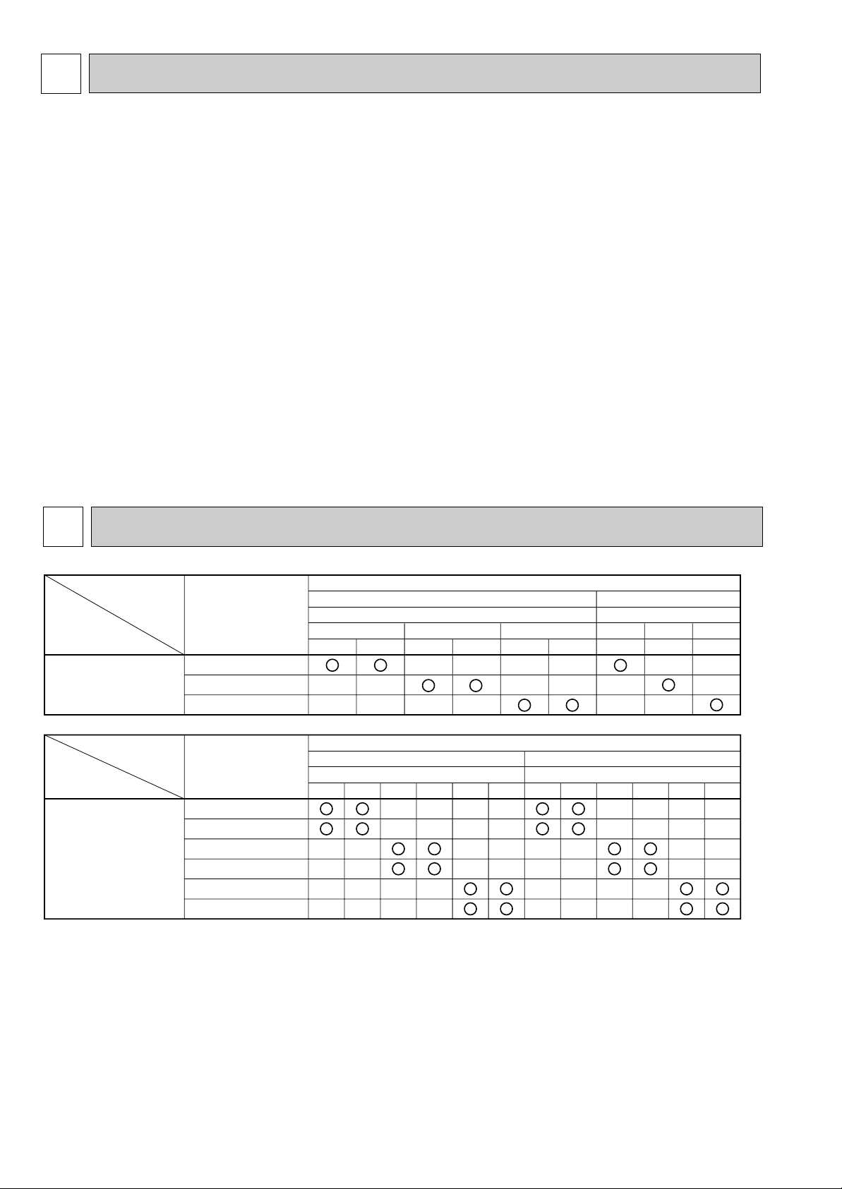
Heat pump type
Outdoor unit
PUH-P
Cooling only type
PU-P
PLA-P1.6KA.UK
PLA-P2KA.UK
PLA-P2.5KA.UK
Heat pump without
electric heater or
Cooling only
VGA1
—
—
VGA
—
—
VGA
—
—
VGA
1
—
—
YGA
1
—
—
YGA
—
—
VGA
—
—
VGA
—
—
YGA
—
—
1.6 2 2.5 1.6 2 2.5
Indoor unit
Heat pump type
Outdoor unit
PUH-P•GAA.UK
Cooling only type
PU-P•GAA.UK
PLA-P1.6KA.UK
PLA-P1.6KA1.UK
PLA-P2KA.UK
PLA-P2KA1.UK
PLA-P2.5KA.UK
PLA-P2.5KA1.UK
Heat pump without
electric heater
or
Cooling only
1.6V
—
—
—
—
1.6Y
—
—
—
—
2V
—
—
—
—
2Y
—
—
—
—
2.5V
—
—
—
—
2.5Y
—
—
—
—
1.6V
—
—
—
—
1.6Y
—
—
—
—
2V
—
—
—
—
2Y
—
—
—
—
2.5V
—
—
—
—
2.5Y
—
—
—
—
Indoor unit
TECHNICAL CHANGES
PLA-P1.6KA.UK ➔ PLA-P1.6KA1.UK PLA-P2KA.UK ➔ PLA-P2KA1.UK
PLA-P2.5KA.UK ➔ PLA-P2.5KA1.UK
● REMOTE CONTROLLER has changed.(PAR-S27A-E ➔ PAR-20MAA-E)
● Outdoor units which are connected to PLA-P·KA.UK and PLA-P·KA
1.UK have been added.
2
COMBINATION OF INDOOR AND OUTDOOR UNITS
2
Page 3

3
SAFETY PRECAUTION
Cautions for using with the outdoor unit which adopts R407C refrigerant.
· Do not use the existing refrigerant piping.
-The old refrigerant and refrigerant oil in the existing piping contains a large amount of chlorine which may cause the refrigerant oil of the new unit to deteriorate.
· Do not use copper pipes which are broken, deformed or discolour .
In addition, be sure that the inner surfaces of the pipes are clean, free of hazardous sulphur and oxides, or have no dust /
dirt, shaving particles, oils, moisture or any other contamination.
-If there is a large amount of residual oil (hydraulic oil, etc.) inside the piping and joints, deterioration of the refrigerant oil will
result.
· Store the piping to be used during installation indoors and keep both ends of the piping sealed until just before
brazing. (Store elbows and other joints in a plastic bag.)
-If dust, dirt, or water enters the refrigerant cycle, deterioration of the oil and compressor trouble may result.
· Use ester oil, ether oil or alkyl benzene (small amount) as the refrigerant oil to coat flares and flange connections.
-The refrigerant oil will degrade if it is mixed with a large amount of mineral oil.
Use liquid refrigerant to fill the system.
-If gas refrigerant is used to fill the system, the composition of the refrigerant in the cylinder will change and performance
may drop.
· Do not use a refrigerant other than R407C.
-If another refrigerant (R22, etc.) is used, the chlorine in the refrigerant may cause the refrigerant oil to deteriorate.
· Use a vacuum pump with a reverse flow check valve.
-The vacuum pump oil may flow back into the refrigerant cycle and cause the refrigerant oil to deteriorate.
· Do not use the following tools that are used with conventional refrigerant.
(Gauge manifold , charge hose, gas leak detector, reverse flow check valve, refrigerant charge base, vacuum gauge,
refrigerant recovery equipment)
-If the conventional refrigerant and refrigerant oil are mixed in the R407C, the refrigerant may deteriorated.
-If water is mixed in the R407C, the refrigerant oil may deteriorate.
-Since R407C does not contain any chlorine, gas leak detectors for conventional refrigerant will not react to it.
· Do not use a charging cylinder.
-Using a charging cylinder may cause the refrigerant to deteriorate.
· Be especially careful when managing the tools.
-if dust, dirt, or water gets in the refrigerant cycle, the refrigerant may deteriorate.
· Do not use the drier which is sold in the field.
-The drier for R407C refrigerant is per-attached to outdoor unit refrigerant circuit.
-Some drier in the field are not in conformity with R407C refrigerant .
3
Page 4
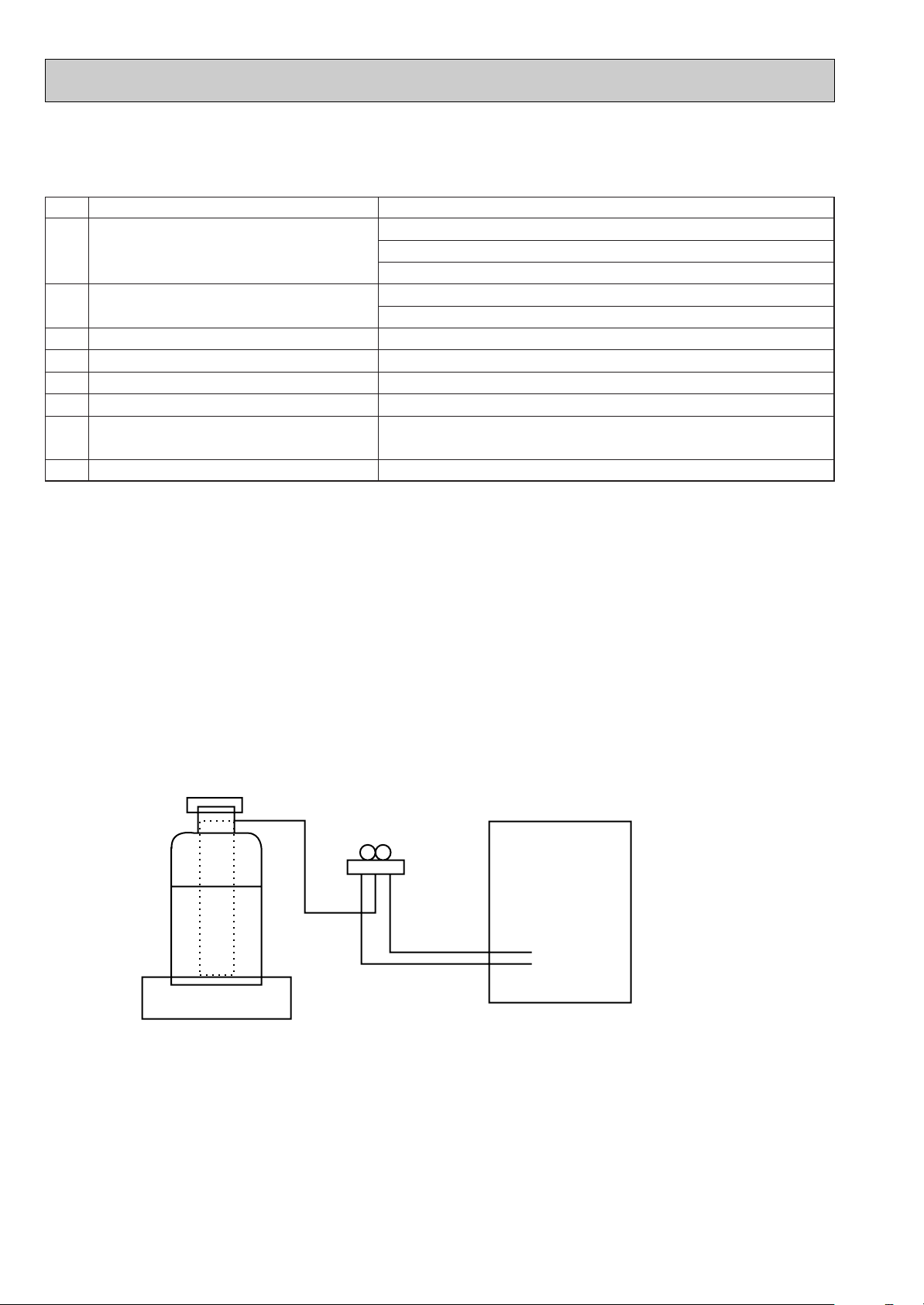
Gravimeter
Unit
[1] Service tools
Use the below service tools as exclusive tools for R407C refrigerant.
No. Tool name Specifications
Gauge manifold ·Only for R407C.
1
·Use the existing fitting SPECIFICATIONS. (UNF7/16)
·Use high-tension side pressure of 3.43MPa·G or over.
Charge hose ·Only for R407C.
2
·Use pressure performance of 5.10MPa·G or over.
Electronic scale
3
Gas leak detector ·Use the detector for R407C.
4
Adapter for reverse flow check. ·Attach on vacuum pump.
5
Refrigerant charge base.
6
Refrigerant cylinder. ·For R407C ·Top of cylinder (Brown)
7
·Cylinder with syphon
Refrigerant recovery equipment.
8
[2] Notice on repair service
·After recovering the all refrigerant in the unit, proceed to working.
·Do not release refrigerant in the air.
·After completing the repair service, recharge the cycle with the specified amount of
liquid refrigerant.
[3] Refrigerant recharging
(1) Refrigerant recharging process
1Direct charging from the cylinder.
·R407C cylinder are available on the market has a syphon pipe.
·Leave the syphon pipe cylinder standing and recharge it.
(By liquid refrigerant)
(2) Recharge in refrigerant leakage case
·After recovering the all refrigerant in the unit, proceed to working.
·Do not release the refrigerant in the air.
·After completing the repair service, recharge the cycle with the specified amount of
liquid refrigerant.
4
Page 5
4
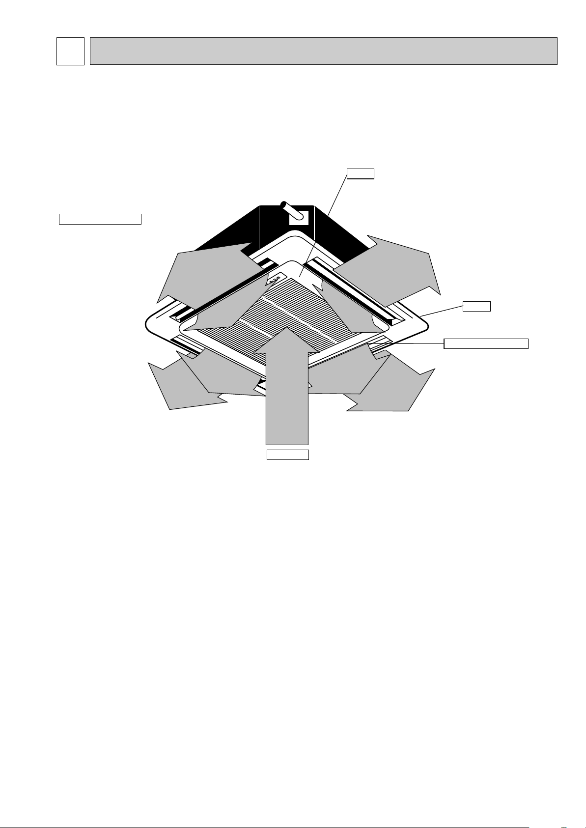
Auto Air Swing Vane
Disperses airflow up and
down and adjusts the angle
of airflow direction.
Grille
Filters
Remove dust and pollutants
from inhaled air
Horizontal Air Outlet
Sets airflow horizontal automatically
during cooling or dehumidifying.
Air Intake
Inhales air from room.
PART NAMES AND FUNCTIONS
● Indoor (Main) Unit
PLA-P1.6KA.UK, PLA-P2KA.UK, PLA-P2.5KA.UK
PLA-P1.6KA1.UK, PLA-P2KA1.UK, PLA-P2.5KA1.UK
5
Page 6
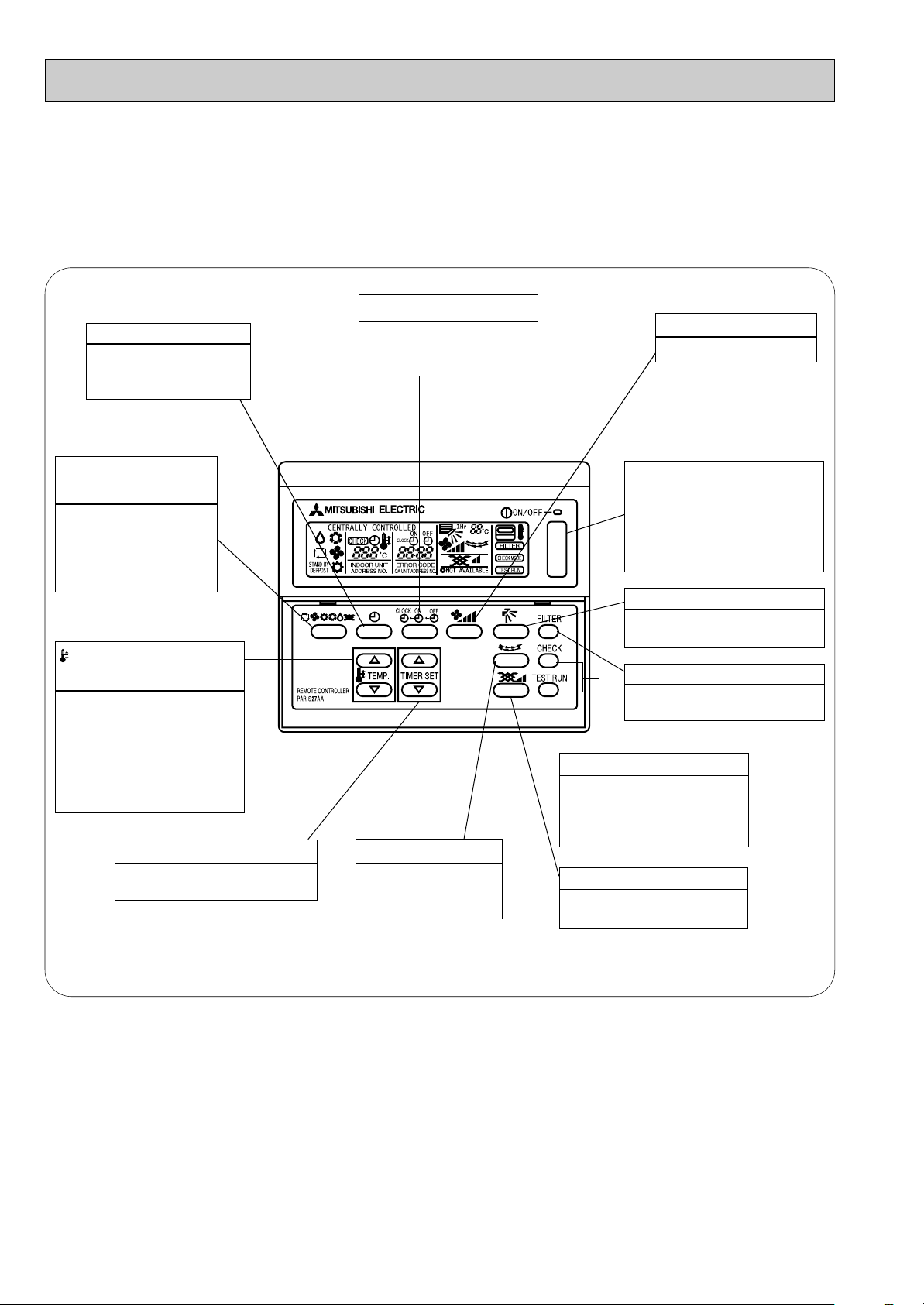
● Remote controller
● Once the controls are set, the same operation mode can
be repeated by simply pressing the ON/OFF button.
PLA-P1.6KA.UK, PLA-P2KA.UK, PLA-P2.5KA.UK
● Operation buttons [ PAR-S27A-E ]
TIME SETTING button
TIMER button
This switches between
continuous operation and
the timer operation.
This sets of switches the
current time. start time and
stop time.
AIR SPEED button
This sets the fan speed.
OPERATION SWITCH
button
Press this button to
switch the cooler electronic dry (dehumidify)
automatic and heater
modes.
TEMP. ADJUSTMENT
button
This sets the room temperature The temperature setting
can be performed in 1°C
units
Setting range
Cooler 19°C to 30°C
Heater 17°C to 28°C
TIMER ADJUSTMENT button
This adjust the current time, start
time and stop time.
LOUVER button
This switches the horizontal fan motion ON
and OFF.
(This button does not
operate in this model)
ON/OFF button
This switches between the
operation and stop modes
each time it is pressed. The
lamp on this button lights during operation.
AIR DIRECTION button
This adjusts the vertical angle
of the ventilation.
FILTER button
This resets the filter cleaning
indication display.
CHECK-TEST RUN button
Only press this button to perform an inspection check or
test operation Do not use it
for normal operation.
VENTILA TION button
This sets the ventilation fan
speed.
6
Page 7
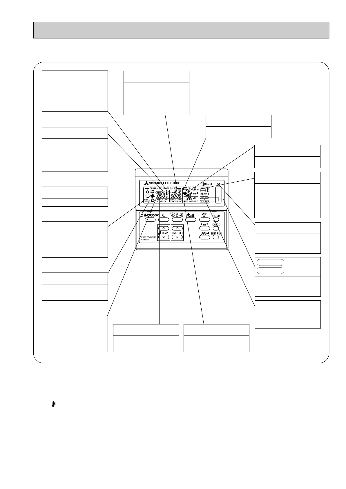
● Display
CENTRALLY
CONTROLLED display
This indicates when the unit is con-
trolled by optional features such as
central control type remote controller.
TIMER display
This indicates when the continuous
operation and time operation modes
are set.
It also display the time for the timer
operation at the same time as when
it is set.
OPERATION MODE display
This indicates the operation mode.
STANDBY display
This indicates when the standby
mode is set from the time the sleep
operation starts until the heating air
is discharged.
DEFROST display
This indicates when the defrost oper-
ation is performed.
CLOCK display
The current time , start time and stop
time can be displayed in ten second
intervals by pressing the time switch
button. The start time or stop time is
always displayed during the timer
operation.
In this display example on the bottom left, a condition where all display lamps light is shown for explanation purposes although this differs
from actual operation.
AIR DIRECTION display
This displays the air direction.
FAN SPEED display
The selected fan speed is displayed.
ROOM TEMPERATURE display
The temperature of the suction air is
displayed during operation. The display range is 8° to 39°C. The display
flashes 8°C when the actual temperature is less than 8° and flashes
39°C when the actual temperature is
greater than 39°C.
Operation lamp
This lamp lights during operation,
goes off when the unit stops and
flashes when a malfunction occurs.
CHECK MODE
TEST RUN
This display lights in the check mode
or when a test operation is performed.
display
FILTER display
CHECK display
This indicates when a malfunction
has occurred in the unit which should
be checked.
SET TEMPERATURE display
This displays the selected setting
temperature.
Caution
● Only the Power display lights when the unit is stopped and power supplied to the unit.
● When power is turned ON for the first time the (CENTRAL CTRL) display appears to go off momentarily but this is not a
malfunction.
● When the central control remote control unit, which is sold separately, is used the ON-OFF button, operation switch button
and TEMP. adjustment button do not operate.
● “NOT AVAILABLE” is displayed when the Air speed button are pressed.This indicates that this room unit is not equipped
with the fan direction adjustment function and the louver function.
● When power is turned ON for the first time, it is normal that “H0” is displayed on the room temperature indication (For max.
2minutes). Please wait until this “H0” indication disappear then start the operation.
POWER display
This lamp lights when electricity is
supplied to the unit.
This lamp lights when the filter need
to be cleaned.
7
Page 8
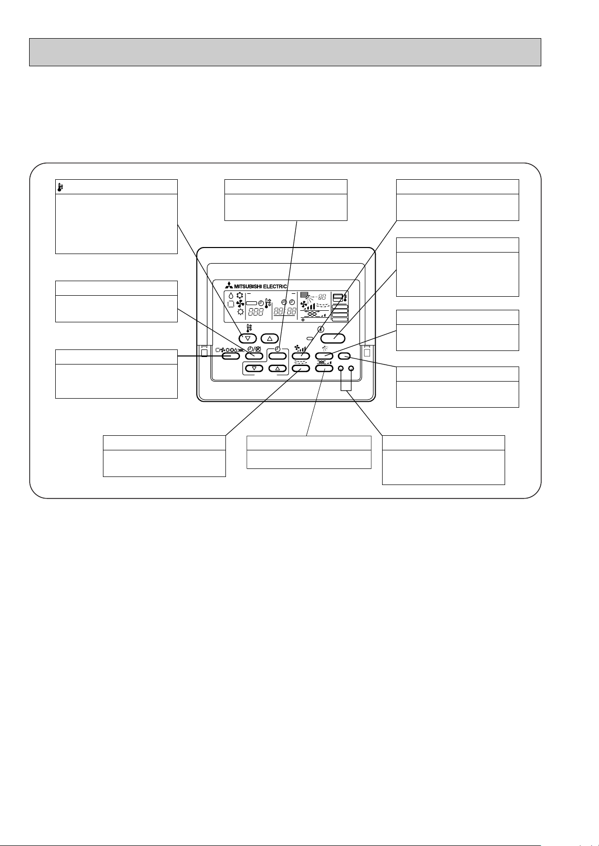
Press this button to switch the cooler,
electronic dry (dehumidify), automatic
and heater modes.
OPERATION SWITCH button
This sets the room temperature. The
temperature setting can be performed
in 1: units
Setting range
Cooler 19: to 30:
Heater 17: to 28:
TEMP. ADJUSTMENT button
This switches between continuous
operation and the timer operation.
TIMER button
This switches between the operation
and stop modes each time it is pressed.
The lamp on this button lights during
operation.
ON/OFF button
Only press this button to perform an
inspection check or test operation.
Do not use it for normal operation.
CHECK-TEST RUN button
This switch the horizontal fan motion
ON and OFF.
(Not available for this model.)
LOUVER button
This adjusts the vertical angle of the
ventilation.
AIR DIRECTION button
This resets the filter service indication
display
FILTER button
This sets the current time, start time
and stop time.
TIME SETTING button
This sets the ventilation fan speed.
AIR SPEED button
This sets the ventilation fan speed.
VENTILATION button
PAR-20MAA
ON/OFF
CENTRALLY CONTROLLED
ERROR CODE
CLOCK
ON OFF
˚C
CHECK
CHECK MODE
FILTER
TEST RUN
FUNCTION
˚C
1Hr.
NOT AVAILABLE
STAND BY
DEFROST
FILTER
CHECK TEST
TEMP.
TIMER SET
PLA-P1.6KA1.UK, PLA-P2KA1.UK, PLA-P2.5KA1.UK
● Operation buttons [PAR-20MAA-E ]
8
Page 9
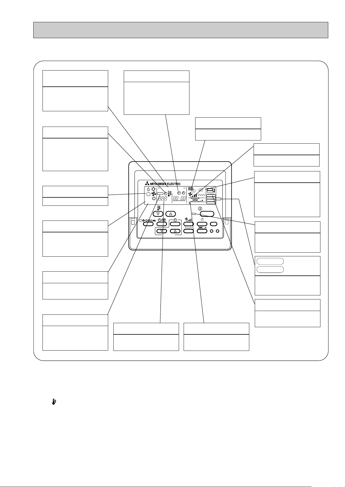
● Display
PAR-20MAA
ON/OFF
CENTRALLY CONTROLLED
ERROR CODE
CLOCK
ON OFF
˚C
CHECK
CHECK MODE
FILTER
TEST RUN
FUNCTION
˚C
1Hr.
NOT AVAILABLE
STAND BY
DEFROST
FILTER
CHECK TEST
TEMP.
TIMER SET
CENTRALLY
CONTROLLED display
This indicates when the unit is controlled by optional features such as
central control type remote controller.
TIMER display
This indicates when the continuous
operation and time operation modes
are set.
It also display the time for the timer
operation at the same time as when
it is set.
OPERATION MODE display
This indicates the operation mode.
STANDBY display
The [STANDBY] symbol is only displayed from the time the heating
operation starts unit the heated air
begins to blow.
DEFROST display
This indicates when the defrost operation is performed.
CLOCK display
The current time , start time and stop
time can be displayed in ten second
intervals by pressing the time switch
button. The start time or stop time is
always displayed during the timer
operation.
In this display example on the bot-
tom left, a condition where all display lamps light is shown for explanation purposes although this differs
from actual operation.
AIR DIRECTION display
This displays the air direction.
AIR SPEED display
The selected fan speed is displayed.
ROOM TEMPERATURE display
The temperature of the suction air
is displayed during operation. The
display range is 8°C to 39°C. The
display flashes 8°C when the actual
temperature is less than 8°C and
flashes 39°C when the actual temperature is greater than 39°C.
Operation lamp
This lamp lights during operation,
goes off when the unit stops and
flashes when a malfunction occurs.
This display lights in the check mode
or when a test operation is performed.
CHECK MODE
TEST RUN
display
FILTER display
CHECK display
This indicates when a malfunction
has occurred in the unit which should
be checked.
SET TEMPERATURE display
This displays the selected setting
temperature.
Caution
● Only the Power display lights when the unit is stopped and power supplied to the unit.
● When the central control remote control unit, which is sold separately, is used the ON-OFF button, operation switch button
and TEMP. adjustment button do not operate.
● “NOT AVAILABLE” is displayed when the Air speed button are pressed.This indicates that this room unit is not equipped
with the fan direction adjustment function and the louver function.
● When power is turned ON for the first time, it is normal that “H0” is displayed on the room temperature indication (For max.
2minutes). Please wait until this “H0” indication disappear then start the operation.
POWER display
This lamp lights when electricity is
supplied to the unit.
This lamp lights when the filter need
to be cleaned.
9
Page 10
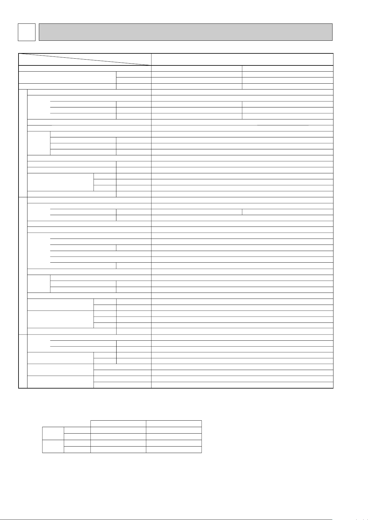
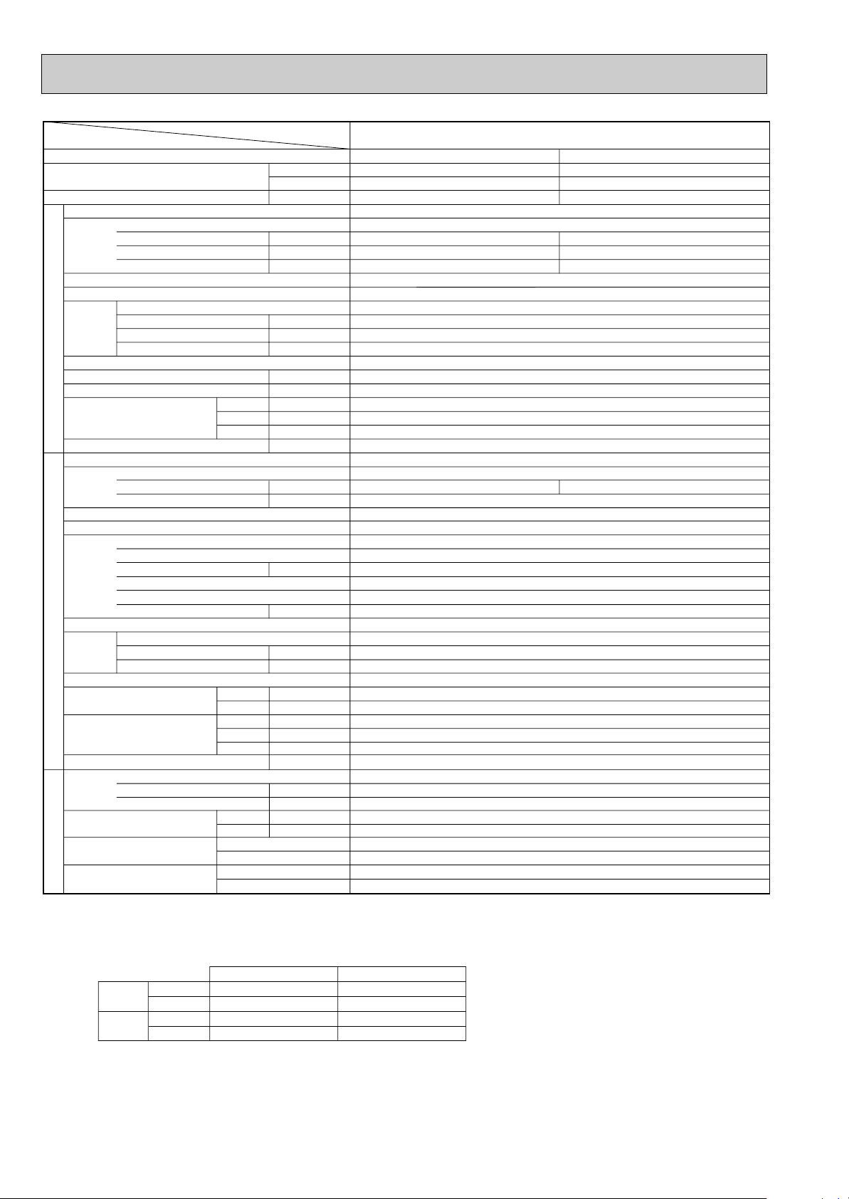
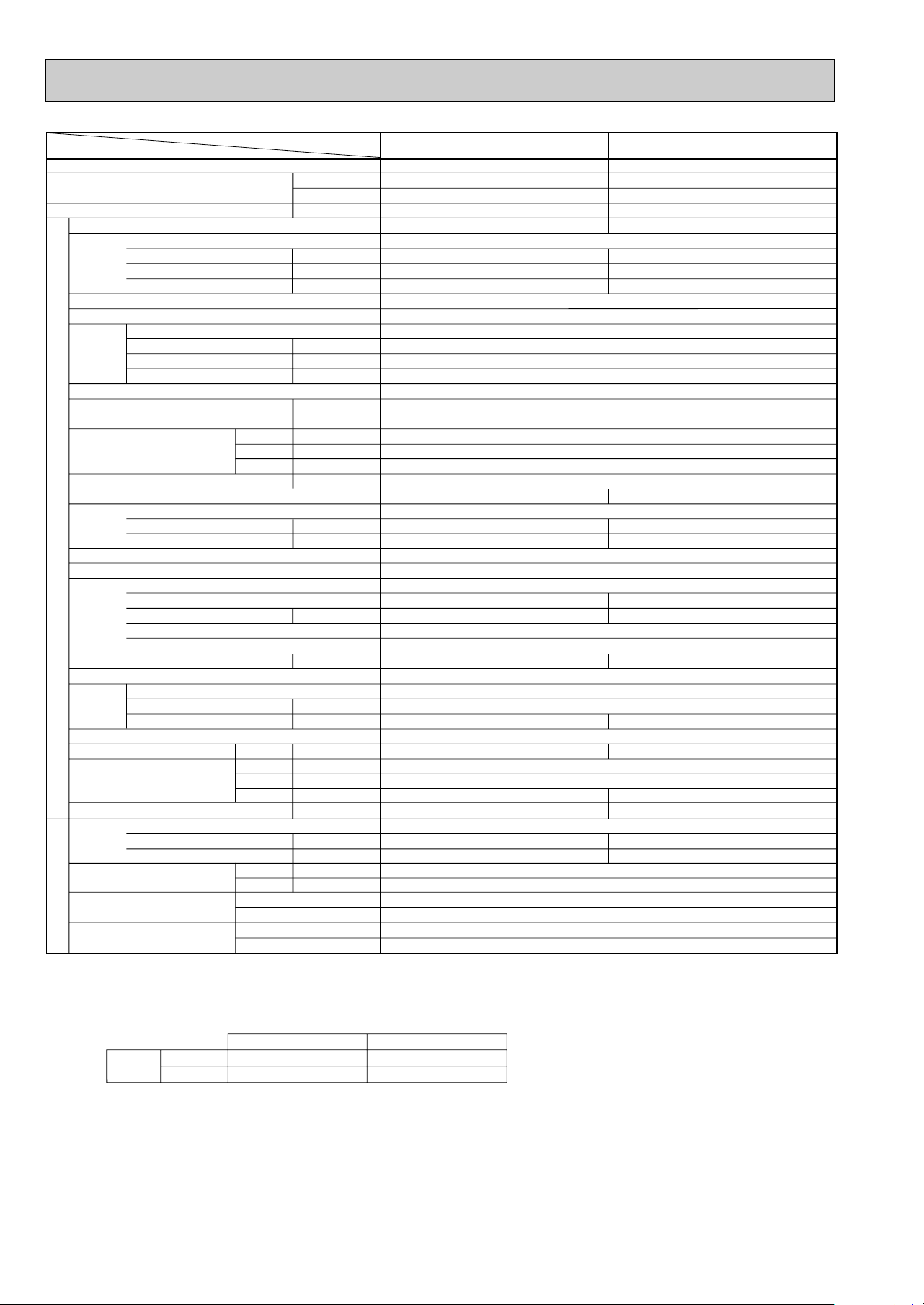
5 SPECIFICATIONS
Service Ref.
Item
Btu/h
W
kW
kW
A
A
kW
K/min(CFM)
Pa(mmAq)
dB
mm(in.)
mm(in.)
mm(in.)
mm(in.)
kg(lbs)
A
A
kW
W
kW
K
/min(CFM
)
dB
dB
mm(in.)
mm(in.)
mm(in.)
kg(lbs)
kg(lbs)
L
mm(in.)
mm(in.)
Function
Capacity
Total input
Service Ref.
Power supply(phase, cycle, voltage)
Input
Running current
Starting current
External finish
Heat exchanger
Fan Fan(drive) x No.
Fan motor output
Airflow(Lo-Mi2-Mi1-Hi)
External static pressure
Operation control & Thermostat
Noise level(Lo-Mi2-Mi1-Hi)
Unit drain pipe I.D.
Dimensions
Weight
Service Ref.
Power supply (phase, cycle, voltage)
Running current
Starting current
External finish
Refrigerant control
Compressor
Model
Motor output
Starter type
Protection devices
Crankcase heater
Heat exchanger
Fan Fan(drive) x No.
Fan motor output
Airflow
Defrost method
Noise level
Dimensions
Weight
Refrigerant
Charge
Oil (Model)
Pipe size O.D.
Connection method
Between the indoor &
outdoor unit
INDOOR UNITOUTDOOR UNIT
REFRIGERANT PIPING
PLA-P1.6KA.UK
Cooling
15,000
4,400
1.86
0.15
0.64
0.70
7.66 / 2.67
Heating
17,100
5,000
1.93
0.10
0.45
0.50
8.19 / 2.86
W
D
H
Cooling
Heating
W
D
H
Liquid
Gas
Indoor side
Outdoor side
Height difference
Piping length
PLA-P1.6KA.UK
Single Phase, 50Hz, 220-230-240V
Galvanized sheets with gray heat insulation
Plate fin coil
Turbo fan (direct) x 1
0.030
13-14-15-16(459-494-530-565)
0(direct blow)
Remote controller & built-in
32-34-35.5-37
32(1-1/4)
PUH-P1.6VGA / PUH-P1.6YGA
Single Phase, 50Hz, 220-230-240V / 3 phases, 50Hz, 380-400-415V(4wires)
36 / 20
Munsell 5Y 8/1
Linear Expansion Valve
Hermetic
RE277VHSM / RE277YFKM
1.3
Line start
Inner thermostat, HP switch, Discharge thermo./ Thermal relay, Discharge thermo, HP switch, Anti-phase protector.
30
Plate fin coil
Propeller (direct) x 1
0.070
45(1,590)
Reverse cycle
46
48
900(35-7/16)
330+20(13+3/4)
650 (25-5/8)
55(121)
R407C
2.6(5.7)
0.57 (Ester)MEL56
9.52 (3/8)
15.88 (5/8)
Flared
Flared
Max. 40m
Max. 40m
Notes1.Rating Conditions (ISO T1)
Cooling :Indoor : D.B. 27˚C(80˚F) W.B. 19˚C (66˚F) Outdoor : D.B. 35˚C(95˚F) W.B. 24˚C (75˚F)
Heating :Indoor : D.B. 20˚C(68˚F) Outdoor : D.B. 7˚C(45˚F) W.B. 6˚C (43˚F)
Refrigerant piping length (one way) : 5m (16ft)
3. Above data based on indicated voltage
Indoor Unit Single phase 240V 50Hz
Outdoor Unit Single phase 240V 50Hz / 3 phases 415V 50Hz
2. Guaranteed operating range
UNIT : 660(26) PANEL : 760(30)
UNIT : 660(26) PANEL : 760(30)
UNIT : 253(10) PANEL : 30(1-3/16)
UNIT : 19(42) PANEL : 3.7(8)
Upper limit
Lower limit
Upper limit
Lower limit
Indoor
Outdoor
Cooling
Heating
D.B. 35˚C W.B. 22.5˚C
D.B. 19˚C W.B. 15˚C
D.B. 28˚C
D.B. 17˚C
D.B. 46˚C
D.B. -5˚C
D.B. 24˚C W.B. 18˚C
D.B. -11˚C W.B. -12˚C
1. Heat pump type
10
Page 11
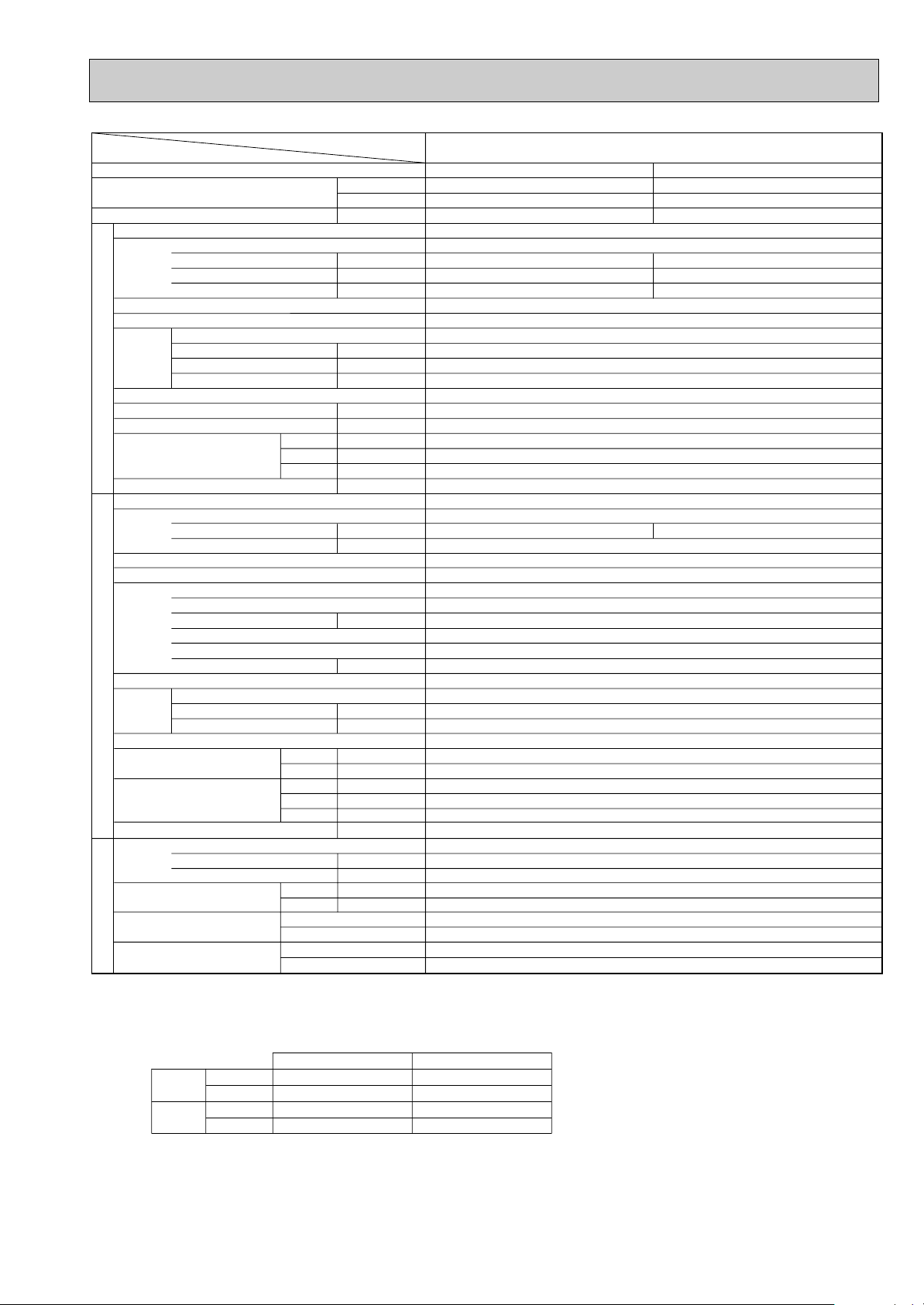
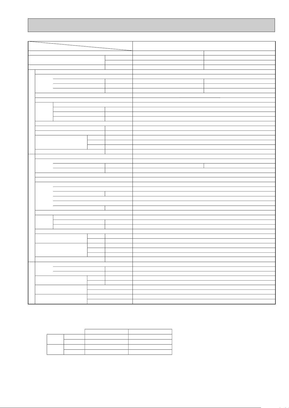
Item
Function
Capacity
Total input
Service Ref.
Power supply(phase, cycle, voltage)
External finish
Heat exchanger
Fan Fan(drive) x No.
INDOOR UNITOUTDOOR UNIT
Operation control & Thermostat
Noise level(Lo-Mi2-Mi1-Hi)
Unit drain pipe I.D.
Dimensions
Weight
Service Ref.
Power supply (phase, cycle, voltage)
External finish
Refrigerant control
Compressor
Heat exchanger
Fan Fan(drive) x No.
Defrost method
Noise level
Dimensions
Weight
Refrigerant
Pipe size O.D.
Connection method
Between the indoor &
REFRIGERANT PIPING
outdoor unit
Notes1.Rating Conditions (ISO T1)
2. Guaranteed operating range
3. Above data based on indicated voltage
Input
Running current
Starting current
Fan motor output
Airflow(Lo-Mi2-Mi1-Hi)
External static pressure
W
D
H
Running current
Starting current
Model
Motor output
Starter type
Protection devices
Crankcase heater
Fan motor output
Airflow
Cooling
Heating
W
D
H
Charge
Oil (Model)
Cooling :Indoor : D.B. 27˚C(80˚F) W.B. 19˚C (66˚F) Outdoor : D.B. 35˚C(95˚F) W.B. 24˚C (75˚F)
Heating :Indoor : D.B. 20˚C(68˚F) Outdoor : D.B. 7˚C(45˚F) W.B. 6˚C (43˚F)
Refrigerant piping length (one way) : 5m (16ft)
Cooling
Heating
Upper limit
Lower limit
Upper limit
Lower limit
Indoor Unit Single phase 240V 50Hz
Outdoor Unit Single phase 240V 50Hz / 3 phases 415V 50Hz
Liquid
Gas
Indoor side
Outdoor side
Height difference
Piping length
D.B. 35˚C W.B. 22.5˚C
D.B. 19˚C W.B. 15˚C
D.B. 28˚C
D.B. 17˚C
Service Ref.
K/min(CFM)
Pa(mmAq)
mm(in.)
mm(in.)
mm(in.)
mm(in.)
kg(lbs)
/min(CFM
K
mm(in.)
mm(in.)
mm(in.)
kg(lbs)
kg(lbs)
mm(in.)
mm(in.)
Indoor
Btu/h
W
kW
kW
A
A
kW
dB
A
A
kW
W
kW
dB
dB
L
Cooling
18,400
5,400
2.62
Single Phase, 50Hz, 220-230-240V
0.14
0.65
0.72
Galvanized sheets with gray heat insulation
Single Phase, 50Hz, 220-230-240V / 3 phases, 50Hz, 380-400-415V(4wires)
11.11 / 3.88
Inner thermostat, HP switch, Discharge thermo./ Thermal relay, Discharge thermo, HP switch, Anti-phase protector.
)
Outdoor
D.B. 46˚C
D.B. -5˚C
D.B. 24˚C W.B. 18˚C
D.B. -11˚C W.B. -12˚C
PLA-P2KA.UK
PLA-P2KA.UK
Turbo fan (direct) x 1
13-14-15-16(459-494-530-565)
0(direct blow)
Remote controller & built-in
32-34-35.5-37
UNIT : 660(26) PANEL : 760(30)
UNIT : 660(26) PANEL : 760(30)
UNIT : 253(10) PANEL : 30(1-3/16)
UNIT : 19(42) PANEL : 3.7(8)
PUH-P2VGA / PUH-P2YGA
Munsell 5Y 8/1
Linear Expansion Valve
NE38VMJM / NE38YEJM
Propeller (direct) x 1
Reverse cycle
900(35-7/16)
330+20(13+3/4)
1.2 (Ester)MEL56
Heating
21,300
6,250
2.67
0.10
0.45
0.50
Plate fin coil
0.030
32(1-1/4)
11.51 / 4.02
74 / 30
Hermetic
1.7
Line start
38
Plate fin coil
0.070
55(1,940)
48
49
855 (33-5/8)
71(157)
R407C
3.1(6.8)
9.52 (3/8)
15.88 (5/8)
Flared
Flared
Max. 40m
Max. 40m
11
Page 12
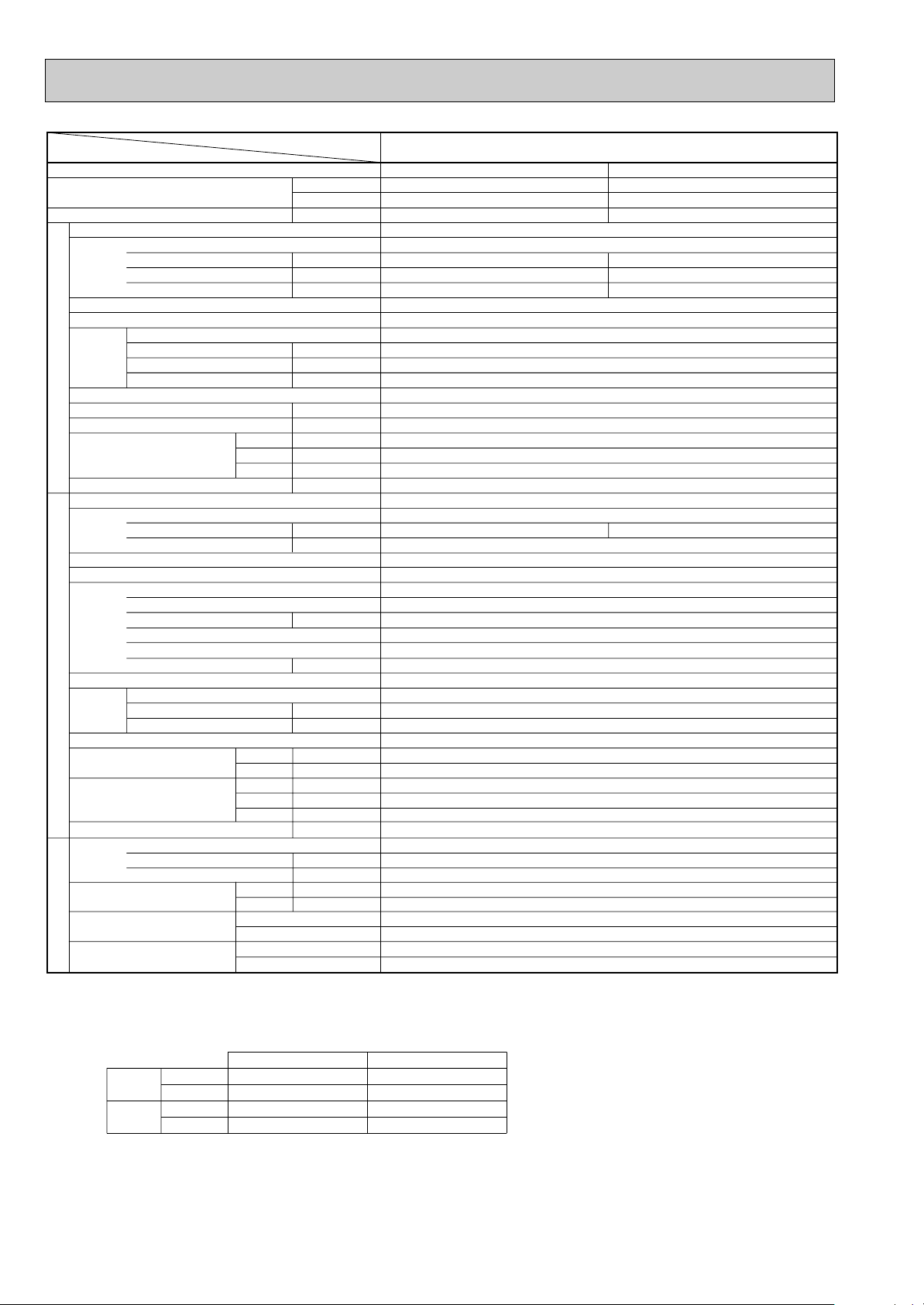
Cooling
21,500
6,300
2.77
0.14
0.61
0.67
11.78 / 4.11
Heating
25,200
7,400
2.68
0.10
0.45
0.50
11.55 / 4.03
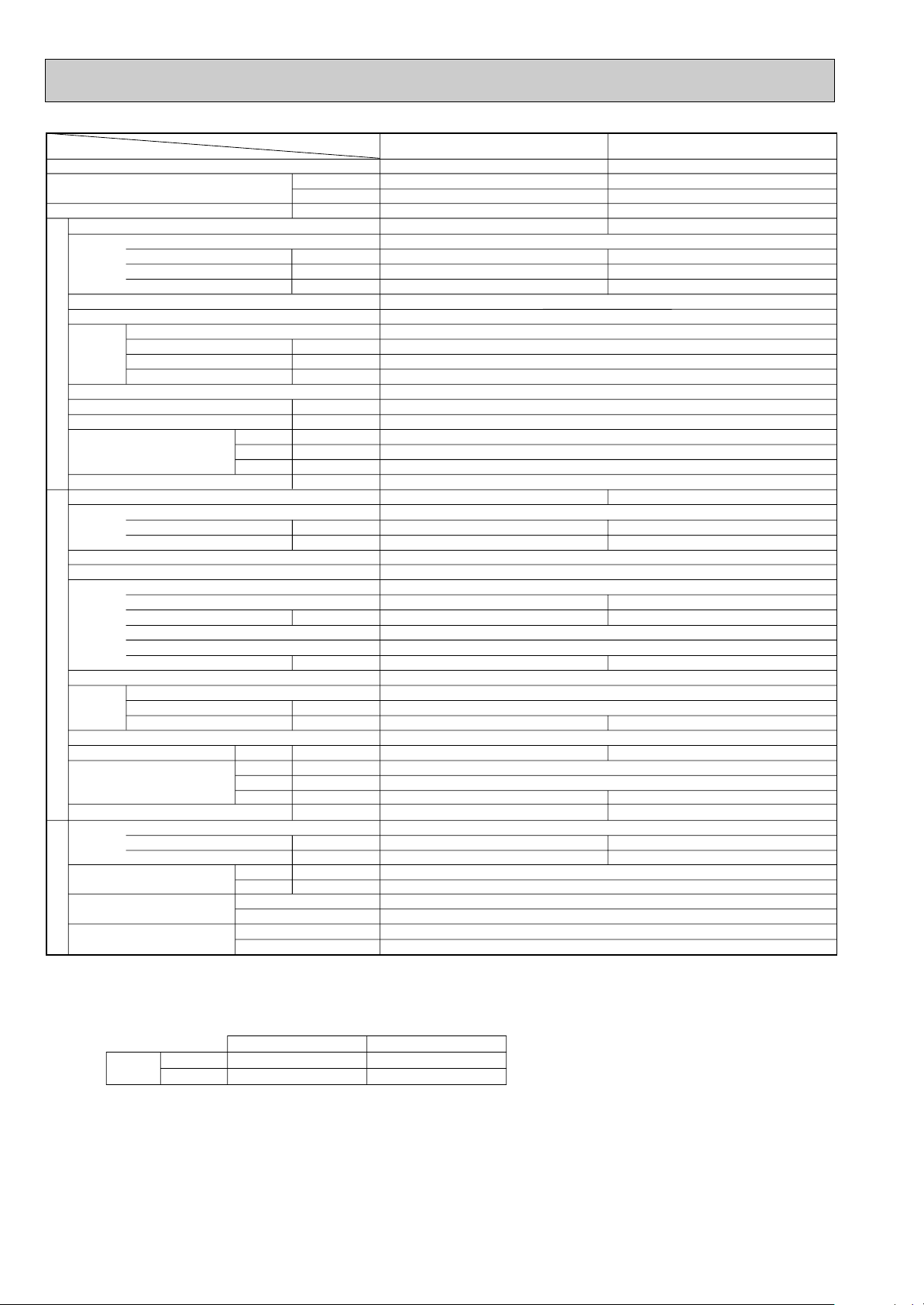
PLA-P2.5KA.UK
Single Phase, 50Hz, 220-230-240V
Galvanized sheets with gray heat insulation
Plate fin coil
Turbo fan (direct) x 1
0.030
14-15-16-17 (494-530-565-600)
0(direct blow)
Remote controller & built-in
35-36.5-38-39.5
32(1-1/4)
PUH-P2.5VGA
1 / PUH-P2.5YGA1
Single Phase, 50Hz, 220-230-240V / 3 phases, 50Hz, 380-400-415V(4wires)
77 / 32
Munsell 5Y 8/1
Linear Expansion Valve
Hermetic
NE41VMJM / NE41YEJM
1.9
Line start
Internal thermostat, HP switch, Discharge thermo./ Thermal relay, Discharge thermo, HP switch, Anti-phase protector.
38
Plate fin coil
Propeller (direct) x 1
0.070
50(1,770)
Reverse cycle
48
50
900(35-7/16)
330+20(13+3/4)
855 (33-5/8)
82(181)
R407C
3.3(7.3)
1.2 (Ester)MEL56
9.52 (3/8)
15.88 (5/8)
Flared
Flared
Max. 50m
Max. 50m
PLA-P2.5KA.UK
UNIT : 660(26) PANEL : 760(30)
UNIT : 660(26) PANEL : 760(30)
UNIT : 253(10) PANEL : 30(1-3/16)
UNIT : 20(44) PANEL : 3.7(8)
Service Ref.
Item
Btu/h
W
kW
kW
A
A
kW
K/min(CFM)
Pa(mmAq)
dB
mm(in.)
mm(in.)
mm(in.)
mm(in.)
kg(lbs)
A
A
kW
W
kW
K
/min(CFM
)
dB
dB
mm(in.)
mm(in.)
mm(in.)
kg(lbs)
kg(lbs)
L
mm(in.)
mm(in.)
Function
Capacity
Total input
Service Ref.
Power supply(phase, cycle, voltage)
Input
Running current
Starting current
External finish
Heat exchanger
Fan Fan(drive) x No.
Fan motor output
Airflow(Lo-Mi2-Mi1-Hi)
External static pressure
Operation control & Thermostat
Noise level(Lo-Mi2-Mi1-Hi)
Unit drain pipe I.D.
Dimensions
Weight
Service Ref.
Power supply (phase, cycle, voltage)
Running current
Starting current
External finish
Refrigerant control
Compressor
Model
Motor output
Starter type
Protection devices
Crankcase heater
Heat exchanger
Fan Fan(drive) x No.
Fan motor output
Airflow
Defrost method
Noise level
Dimensions
Weight
Refrigerant
Charge
Oil (Model)
Pipe size O.D.
Connection method
Between the indoor &
outdoor unit
INDOOR UNITOUTDOOR UNIT
REFRIGERANT PIPING
W
D
H
Cooling
Heating
W
D
H
Liquid
Gas
Indoor side
Outdoor side
Height difference
Piping length
Notes1.Rating Conditions (ISO T1)
Cooling :Indoor : D.B. 27˚C(80˚F) W.B. 19˚C (66˚F) Outdoor : D.B. 35˚C(95˚F) W.B. 24˚C (75˚F)
Heating :Indoor : D.B. 20˚C(68˚F) Outdoor : D.B. 7˚C(45˚F) W.B. 6˚C (43˚F)
Refrigerant piping length (one way) : 5m (16ft)
3. Above data based on indicated voltage
Indoor Unit Single phase 240V 50Hz
Outdoor Unit Single phase 240V 50Hz / 3 phases 415V 50Hz
2. Guaranteed operating range
Upper limit
Lower limit
Upper limit
Lower limit
Indoor
Outdoor
Cooling
Heating
D.B. 35˚C W.B. 22.5˚C
D.B. 19˚C W.B. 15˚C
D.B. 28˚C
D.B. 17˚C
D.B. 46˚C
D.B. -5˚C
D.B. 24˚C W.B. 18˚C
D.B. -11˚C W.B. -12˚C
12
Page 13
W
D
H
W
D
H
Indoor
D.B. 28˚C
D.B. 17˚C
Service Ref.
Btu/h
W
kW
kW
A
A
kW
K/min(CFM)
Pa(mmAq)
dB
mm(in.)
mm(in.)
mm(in.)
mm(in.)
kg(lbs)
A
A
kW
W
kW
K
/min(CFM
dB
dB
mm(in.)
mm(in.)
mm(in.)
kg(lbs)
kg(lbs)
L
mm(in.)
mm(in.)
Single phase, 50Hz, 220-230-240V / 3phases,50Hz,380-400-415V(4wies)
Internal thermostat, HP switch, Discharge thermo./ Thermal relay, HP switch, Discharge thermo.
)
Outdoor
D.B. 46˚C
D.B. -5˚C
D.B. 24˚C W.B. 18˚C
D.B. -11˚C W.B. -12˚C
Item
Function
Capacity
Total input
Service Ref.
Power supply(phase, cycle,voltage)
External finish
Heat exchanger
Fan Fan(drive) x No.
INDOOR UNITOUTDOOR UNIT
Operation control & Thermostat
Noise level(Lo-Mi2-Mi1-Hi)
Unit drain pipe I.D.
Dimensions
Weight
Service Ref.
Power supply (phase, cycle, voltage)
External finish
Refrigerant control
Compressor
Heat exchanger
Fan Fan(drive) x No.
Defrost method
Noise level
Dimensions
Weight
Refrigerant
Pipe size O.D.
Connection method
Between the indoor &
REFRIGERANT PIPING
outdoor unit
Notes1.Rating Conditions (ISO T1)
2. Guaranteed operating range
3. Above data based on indicated voltage
Input
Running current
Starting current
Fan motor output
Airflow(Lo-Mi2-Mi1-Hi)
External static pressure
Running current
Starting current
Model
Motor output
Starter type
Protection devices
Crankcase heater
Fan motor output
Airflow
Cooling
Heating
Charge
Oil (Model)
Cooling :Indoor : D.B. 27˚C(80˚F) W.B. 19˚C (66˚F) Outdoor : D.B. 35˚C(95˚F) W.B. 24˚C (75˚F)
Heating :Indoor : D.B. 20˚C(68˚F) Outdoor : D.B. 7˚C(45˚F) W.B. 6˚C (43˚F)
Refrigerant piping length (one way) : 5m (16ft)
Cooling
Heating
Upper limit
Lower limit
Upper limit
Lower limit
Indoor Unit Single phase 240V 50Hz
Outdoor Unit Single phase 240V 50Hz / 3phases 415V 50Hz
Liquid
Gas
Indoor side
Outdoor side
Height difference
Piping length
D.B. 35˚C W.B. 22.5˚C
D.B. 19˚C W.B. 15˚C
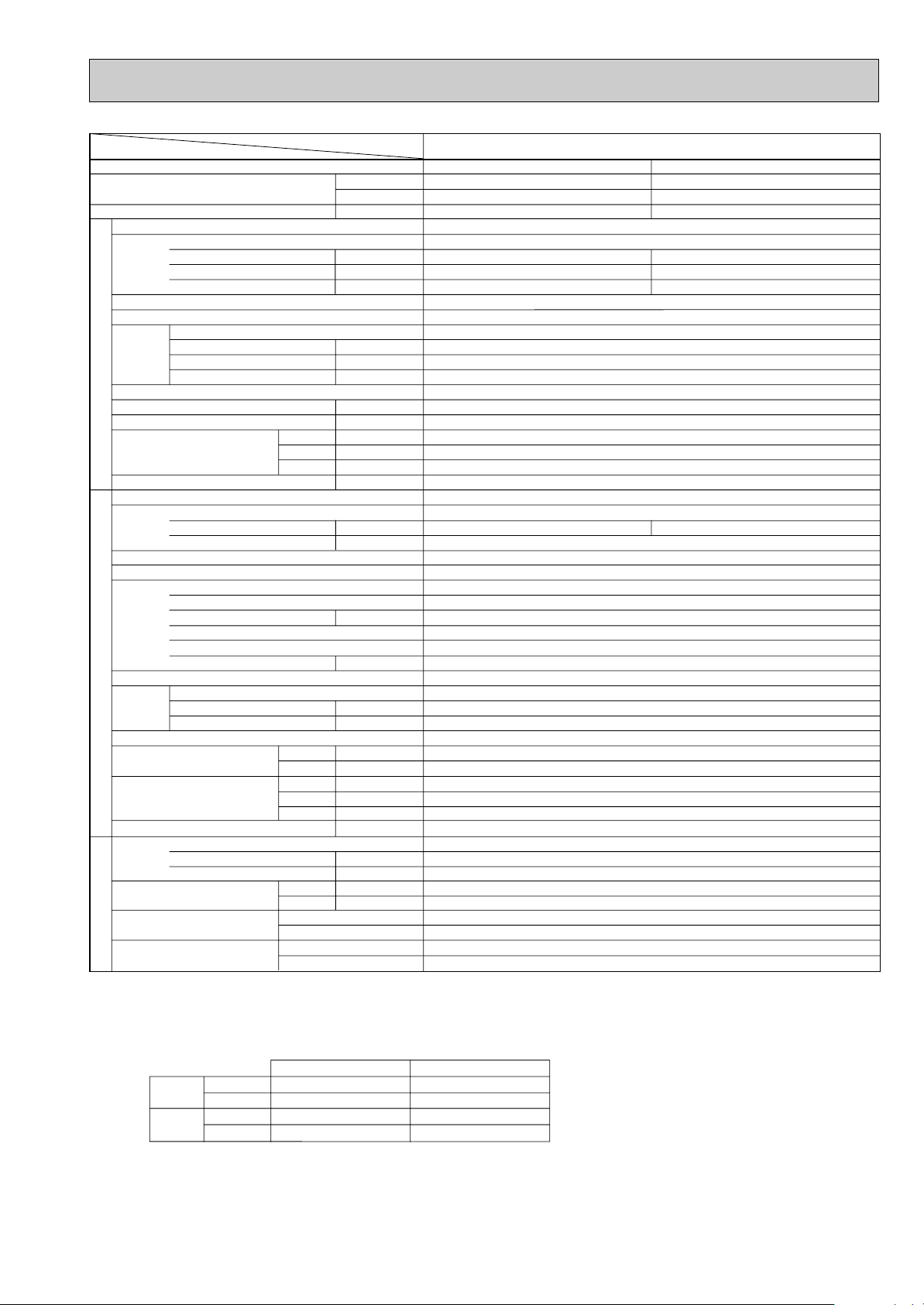
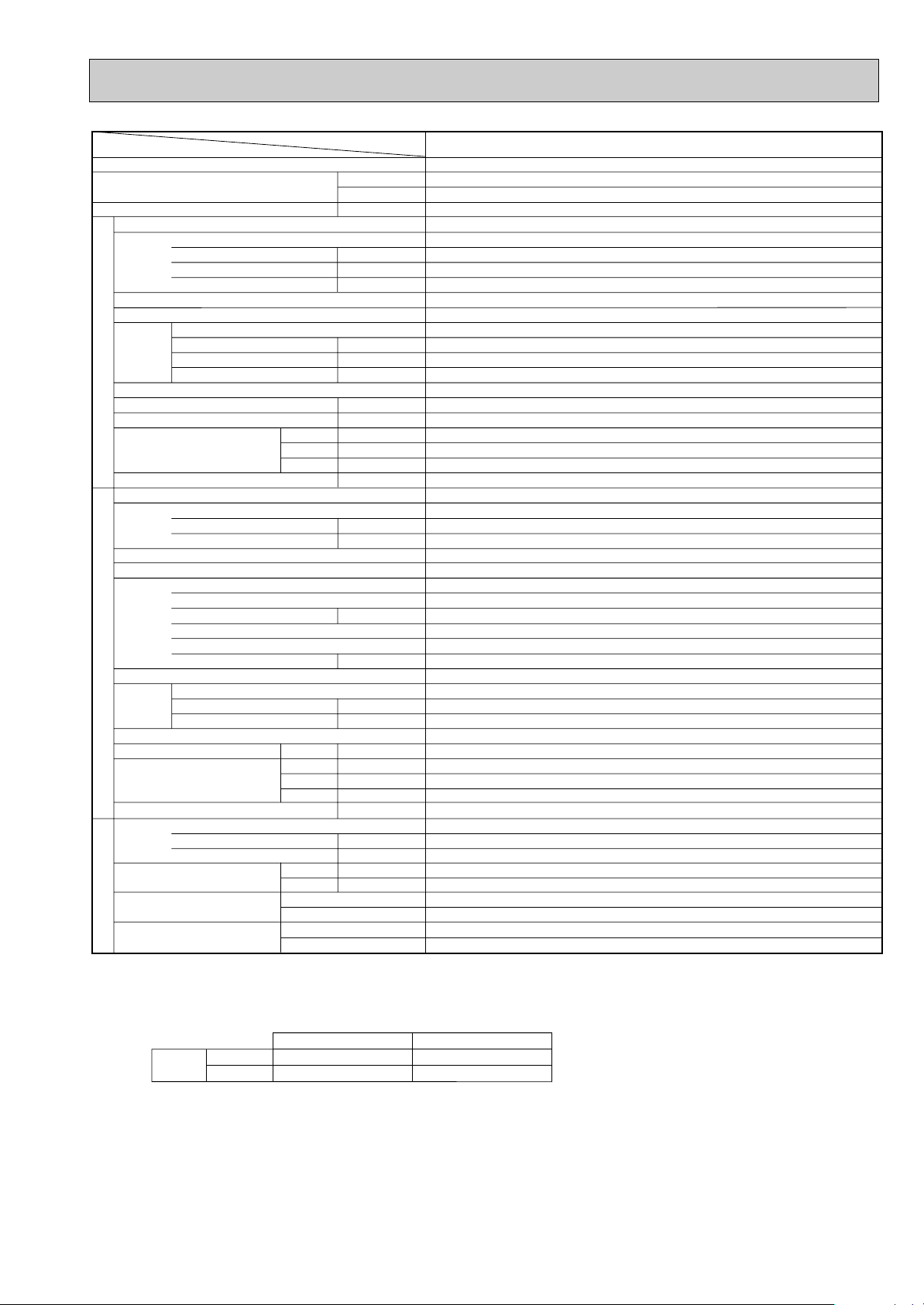
PLA-P1.6KA.UK / PLA-P1.6KA1.UK
Cooling
15,000
4,400
1.82
PLA-P1.6KA.UK / PLA-P1.6KA1.UK
Single phase, 50Hz, 220-230-240V
0.15
0.64
0.70
Galvanized sheets with gray heat insulation
Turbo fan (direct) x 1
13-14-15-16 (459-494-530-565)
Remote controller & built-in
UNIT : 660(26) PANEL : 760(30)
UNIT : 660(26) PANEL : 760(30)
UNIT : 253(10) PANEL : 30(1-3/16)
UNIT : 19(42) PANEL : 3.7(8)
PUH-P1.6VGAA.UK / PUH-P1.6YGAA.UK
7.36 / 2.49
Linear Expansion Valve
RE277VHSMT / RE277YFKM
Propeller (direct) x 1
0.57(Ester)MEL56
Heating
17,100
5,000
1.89
0.10
0.45
0.50
Plate fin coil
0.030
0(direct blow)
32-34-35.5-37
32(1-1/4)
7.59 / 2.56
36 / 20
Munsell 5Y 7/1
Hermetic
1.3
Line start
Plate fin coil
0.070
45(1,590)
30
Reverse cycle
47
49
900(35-7/16)
330+20(13+3/4)
650(25-5/8)
55(121)
R407C
2.5(5.5)
9.52 (3/8)
15.88 (5/8)
Flared
Flared
Max. 40m
Max. 40m
13
Page 14
Cooling
18,000
5,300
2.44
0.14
0.65
0.72
10.26 / 3.70
Heating
20,300
5,950
2.40
0.10
0.45
0.50
10.57 / 3.82
PLA-P2KA.UK / PLA-P2KA1.UK
Single phase, 50Hz, 220-230-240V
Galvanized sheets with gray heat insulation
Plate fin coil
Turbo fan (direct) x 1
0.030
13-14-15-16(459-494-530-565)
0(direct blow)
Remote controller & built-in
32-34-35.5-37
32(1-1/4)
PUH-P2VGAA.UK / PUH-P2YGAA.UK
Single Phase, 50Hz, 220-230-240V / 3 phases, 50Hz, 380-400-415V(4wires)
62 / 31
Munsell 5Y 7/1
Linear Expansion Valve
Hermetic
NE36VMJMT / NE36YEKMT
1.6
Line start
Inner thermostat, HP switch, Discharge thermo./ Thermal relay, HP switch, Discharge thermo
38
Plate fin coil
Propeller (direct) x 1
0.070
55(1,940)
Reverse cycle
48
49
900(35-7/16)
330+20(13+3/4)
855 (33-5/8)
71(157)
R407C
2.6(5.7)
1.2 (Ester)MEL56
9.52 (3/8)
15.88 (5/8)
Flared
Flared
Max. 40m
Max. 40m
UNIT : 660(26) PANEL : 760(30)
UNIT : 660(26) PANEL : 760(30)
UNIT : 253(10) PANEL : 30(1-3/16)
UNIT : 19(42) PANEL : 3.7(8)
Service Ref.
Item
Btu/h
W
kW
kW
A
A
kW
K/min(CFM)
Pa(mmAq)
dB
mm(in.)
mm(in.)
mm(in.)
mm(in.)
kg(lbs)
A
A
kW
W
kW
K
/min(CFM
)
dB
dB
mm(in.)
mm(in.)
mm(in.)
kg(lbs)
kg(lbs)
L
mm(in.)
mm(in.)
Function
Capacity
Total input
Service Ref.
Power supply(phase, cycle, voltage)
Input
Running current
Starting current
External finish
Heat exchanger
Fan Fan(drive) x No.
Fan motor output
Airflow(Lo-Mi2-Mi1-Hi)
External static pressure
Operation control & Thermostat
Noise level(Lo-Mi2-Mi1-Hi)
Unit drain pipe I.D.
Dimensions
Weight
Service Ref.
Power supply (phase, cycle, voltage)
Running current
Starting current
External finish
Refrigerant control
Compressor
Model
Motor output
Starter type
Protection devices
Crankcase heater
Heat exchanger
Fan Fan(drive) x No.
Fan motor output
Airflow
Defrost method
Noise level
Dimensions
Weight
Refrigerant
Charge
Oil (Model)
Pipe size O.D.
Connection method
Between the indoor &
outdoor unit
INDOOR UNITOUTDOOR UNIT
REFRIGERANT PIPING
PLA-P2KA.UK / PLA-P2KA1.UK
W
D
H
Cooling
Heating
W
D
H
Liquid
Gas
Indoor side
Outdoor side
Height difference
Piping length
Notes1.Rating Conditions (ISO T1)
Cooling :Indoor : D.B. 27˚C(80˚F) W.B. 19˚C (66˚F) Outdoor : D.B. 35˚C(95˚F) W.B. 24˚C (75˚F)
Heating :Indoor : D.B. 20˚C(68˚F) Outdoor : D.B. 7˚C(45˚F) W.B. 6˚C (43˚F)
Refrigerant piping length (one way) : 5m (16ft)
3. Above data based on indicated voltage
Indoor Unit Single phase 240V 50Hz
Outdoor Unit Single phase 240V 50Hz / 3 phases 415V 50Hz
2. Guaranteed operating range
Upper limit
Lower limit
Upper limit
Lower limit
Indoor
Outdoor
Cooling
Heating
D.B. 35˚C W.B. 22.5˚C
D.B. 19˚C W.B. 15˚C
D.B. 28˚C
D.B. 17˚C
D.B. 46˚C
D.B. -5˚C
D.B. 24˚C W.B. 18˚C
D.B. -11˚C W.B. -12˚C
14
Page 15
W
D
H
W
D
H
Service Ref.
K/min(CFM)
Pa(mmAq)
mm(in.)
mm(in.)
mm(in.)
mm(in.)
kg(lbs)
/min(CFM
K
mm(in.)
mm(in.)
mm(in.)
kg(lbs)
kg(lbs)
mm(in.)
mm(in.)
Indoor
Btu/h
W
kW
kW
A
A
kW
dB
A
A
kW
W
kW
dB
dB
L
Single Phase, 50Hz, 220-230-240V / 3 phases, 50Hz, 380-400-415V(4wires)
11.90 / 4.48
Internal thermostat, HP switch, Discharge thermo./ Thermal relay, HP switch, Discharge thermo
)
Outdoor
D.B. 46˚C
D.B. -5˚C
D.B. 24˚C W.B. 18˚C
D.B. -11˚C W.B. -12˚C
Item
Function
Capacity
Total input
Service Ref.
Power supply(phase, cycle, voltage)
External finish
Heat exchanger
Fan Fan(drive) x No.
INDOOR UNITOUTDOOR UNIT
Operation control & Thermostat
Noise level(Lo-Mi2-Mi1-Hi)
Unit drain pipe I.D.
Dimensions
Weight
Service Ref.
Power supply (phase, cycle, voltage)
External finish
Refrigerant control
Compressor
Heat exchanger
Fan Fan(drive) x No.
Defrost method
Noise level
Dimensions
Weight
Refrigerant
Pipe size O.D.
Connection method
Between the indoor &
REFRIGERANT PIPING
outdoor unit
Notes1.Rating Conditions (ISO T1)
2. Guaranteed operating range
3. Above data based on indicated voltage
Input
Running current
Starting current
Fan motor output
Airflow(Lo-Mi2-Mi1-Hi)
External static pressure
Running current
Starting current
Model
Motor output
Starter type
Protection devices
Crankcase heater
Fan motor output
Airflow
Cooling
Heating
Charge
Oil (Model)
Cooling :Indoor : D.B. 27˚C(80˚F) W.B. 19˚C (66˚F) Outdoor : D.B. 35˚C(95˚F) W.B. 24˚C (75˚F)
Heating :Indoor : D.B. 20˚C(68˚F) Outdoor : D.B. 7˚C(45˚F) W.B. 6˚C (43˚F)
Refrigerant piping length (one way) : 5m (16ft)
Cooling
Heating
Upper limit
Lower limit
Upper limit
Lower limit
Indoor Unit Single phase 240V 50Hz
Outdoor Unit Single phase 240V 50Hz / 3 phases 415V 50Hz
Liquid
Gas
Indoor side
Outdoor side
Height difference
Piping length
D.B. 35˚C W.B. 22.5˚C
D.B. 19˚C W.B. 15˚C
D.B. 28˚C
D.B. 17˚C
PLA-P2.5KA.UK / PLA-P2.5KA
Cooling
21,500
6,300
2.63
PLA-P2.5KA.UK / PLA-P2.5KA
Single phase, 50Hz, 220-230-240V
0.14
0.61
0.67
Galvanized sheets with gray heat insulation
Turbo fan (direct) x 1
14-15-16-17 (494-530-565-600)
0(direct blow)
Remote controller & built-in
35-36.5-38-39.5
UNIT : 660(26) PANEL : 760(30)
UNIT : 660(26) PANEL : 760(30)
UNIT : 253(10) PANEL : 30(1-3/16)
UNIT : 20(44) PANEL : 3.7(8)
PUH-P2.5VGAA.UK / PUH-P2.5YGAA.UK
Munsell 5Y 7/1
Linear Expansion Valve
NE41VMJMT / NE41YEKMT
Propeller (direct) x 1
Reverse cycle
900(35-7/16)
330+20(13+3/4)
1.2 (Ester)MEL56
1.UK
Heating
25,200
7,400
2.57
1.UK
0.10
0.45
0.50
Plate fin coil
0.030
32(1-1/4)
11.51 / 4.34
77 / 35
Hermetic
1.9
Line start
38
Plate fin coil
0.070
50(1,770)
48
50
855 (33-5/8)
82(181)
R407C
3.1(6.8)
9.52 (3/8)
15.88 (5/8)
Flared
Flared
Max. 50m
Max. 50m
15
Page 16
2. Cooling only type
Service Ref.
Item
Btu/h
W
kW
kW
A
A
kW
K/min(CFM)
Pa(mmAq)
dB
mm(in.)
mm(in.)
mm(in.)
mm(in.)
kg(lbs)
A
A
kW
W
kW
K
/min(CFM
)
dB
mm(in.)
mm(in.)
mm(in.)
kg(lbs)
kg(lbs)
L
mm(in.)
mm(in.)
Function
Capacity
Total input
Service Ref.
Power supply(phase, cycle,voltage)
Input
Running current
Starting current
External finish
Heat exchanger
Fan Fan(drive) x No.
Fan motor output
Airflow(Lo-Mi2-Mi1-Hi)
External static pressure
Operation control & Thermostat
Noise level(Lo-Mi2-Mi1-Hi)
Unit drain pipe I.D.
Dimensions
Weight
Service Ref.
Power supply (phase, cycle, voltage)
Running current
Starting current
External finish
Refrigerant control
Compressor
Model
Motor output
Starter type
Protection devices
Crankcase heater
Heat exchanger
Fan Fan(drive) x No.
Fan motor output
Airflow
Defrost method
Noise level
Dimensions
Weight
Refrigerant
Charge
Oil (Model)
Pipe size O.D.
Connection method
Between the indoor &
outdoor unit
INDOOR UNITOUTDOOR UNIT
REFRIGERANT PIPING
PLA-P1.6KA.UK
PLA-P1.6KA.UK
PLA-P2KA.UK
PLA-P2KA.UK
Cooling
15,000
4,400
1.86
0.15
0.64
0.70
PU-P1.6VGA
7.66
36
RE277VHSM
1.3
30
45(1,590)
46
650 (25-5/8)
55(121)
2.6(5.7)
0.57(Ester)MEL56
Cooling
18,400
5,400
2.62
0.14
0.65
0.72
PU-P2VGA
11.11
74
NE38VMJM
1.7
38
55(1,940)
48
855(33-5/8)
71(157)
3.1(6.8)
1.2(Ester)MEL56
W
D
H
Cooling
W
D
H
Liquid
Gas
Indoor side
Outdoor side
Height difference
Piping length
Single phase, 50Hz, 220-230-240V
Galvanized sheets with gray heat insulation
Plate fin coil
Turbo fan (direct) x 1
0.030
13-14-15-16(459-494-530-565)
0(direct blow)
Remote controller & built-in
32-34-35.5-37
32(1-1/4)
Single phase, 50Hz, 220-230-240V
Munsell 5Y 8/1
Linear Expansion Valve
Hermetic
Line start
Inner thermostat, High pressure switch, Discharge thermo.
Plate fin coil
Propeller (direct) x 1
0.070
—
900(35-7/16)
330+20(13+3/4)
R407C
9.52 (3/8)
15.88 (5/8)
Flared
Flared
Max. 40m
Max. 40m
Notes1.Rating Conditions (ISO T1)
Cooling :Indoor : D.B. 27˚C(80˚F) W.B. 19˚C (66˚F) Outdoor : D.B. 35˚C(95˚F) W.B. 24˚C (75˚F)
Refrigerant piping length (one way) : 5m (16ft)
3. Above data based on indicated voltage
Indoor Unit Single phase 240V 50Hz
Outdoor Unit Single phase 240V 50Hz
2. Guaranteed operating range
Upper limit
Lower limit
Indoor
Outdoor
Cooling
UNIT : 660(26) PANEL : 760(30)
UNIT : 660(26) PANEL : 760(30)
UNIT : 253(10) PANEL : 30(1-3/16)
UNIT : 19(42) PANEL : 3.7(8)
D.B. 35˚C W.B. 22.5˚C
D.B. 19˚C W.B. 15˚C
D.B. 46˚C
D.B. -5˚C
16
Page 17
W
D
H
W
D
H
Service Ref.
Btu/h
W
kW
kW
A
A
kW
K/min(CFM)
Pa(mmAq)
dB
mm(in.)
mm(in.)
mm(in.)
mm(in.)
kg(lbs)
A
A
kW
W
kW
/min(CFM
K
dB
mm(in.)
mm(in.)
mm(in.)
kg(lbs)
kg(lbs)
L
mm(in.)
mm(in.)
Single phase, 50Hz, 220-230-240V
Galvanized sheets with gray heat insulation
UNIT : 660(26) PANEL : 760(30)
UNIT : 660(26) PANEL : 760(30)
UNIT : 253(10) PANEL : 30(1-3/16)
UNIT : 20(44) PANEL : 3.7(8)
Single Phase, 50Hz, 220-230-240V
Internal thermostat, High pressure switch, Discharge thermo.
)
Item
Function
Capacity
Total input
Service Ref.
Power supply(phase, cycle,voltage)
External finish
Heat exchanger
Fan Fan(drive) x No.
INDOOR UNITOUTDOOR UNIT
Operation control & Thermostat
Noise level(Lo-Mi2-Mi1-Hi)
Unit drain pipe I.D.
Dimensions
Weight
Service Ref.
Power supply (phase, cycle, voltage)
External finish
Refrigerant control
Compressor
Heat exchanger
Fan Fan(drive) x No.
Defrost method
Noise level
Dimensions
Weight
Refrigerant
Pipe size O.D.
Connection method
Between the indoor &
REFRIGERANT PIPING
outdoor unit
Notes1.Rating Conditions (ISO T1)
Input
Running current
Starting current
Fan motor output
Airflow(Lo-Mi2-Mi1-Hi)
External static pressure
Running current
Starting current
Model
Motor output
Starter type
Protection devices
Crankcase heater
Fan motor output
Airflow
Cooling
Charge
Oil (Model)
Liquid
Gas
Indoor side
Outdoor side
Height difference
Piping length
Cooling :Indoor : D.B. 27˚C(80˚F) W.B. 19˚C (66˚F) Outdoor : D.B. 35˚C(95˚F) W.B. 24˚C (75˚F)
Refrigerant piping length (one way) : 5m (16ft)
PLA-P2.5KA.UK
PLA-P2.5KA.UK
Turbo fan (direct) x 1
14-15-16-17 (494-530-565-600)
Remote controller & built-in
Linear Expansion Valve
Propeller (direct) x 1
1.2(Ester)MEL56
Cooling
21,500
6,300
2.77
0.14
0.61
0.67
Plate fin coil
0.030
0(direct blow)
35-36.5-38-39.5
32(1-1/4)
PU-P2.5VGA
11.78
77
Munsell 5Y 8/1
Hermetic
NE41VMJM
1.9
Line start
38
Plate fin coil
0.070
50(1,770)
—
48
900(35-7/16)
330+20(13+3/4)
855(33-5/8)
82(181)
R407C
3.3(7.3)
9.52 (3/8)
15.88 (5/8)
Flared
Flared
Max. 50m
Max. 50m
1
2. Guaranteed operating range
Indoor
Cooling
3. Above data based on indicated voltage
Upper limit
Lower limit
Indoor Unit Single phase 240V 50Hz
Outdoor Unit Single phase 240V 50Hz / 3 phases 415V 50Hz
D.B. 35˚C W.B. 22.5˚C
D.B. 19˚C W.B. 15˚C
Outdoor
D.B. 46˚C
D.B. -5˚C
17
Page 18
Service Ref.
Item
Btu/h
W
kW
kW
A
A
kW
K/min(CFM)
Pa(mmAq)
dB
mm(in.)
mm(in.)
mm(in.)
mm(in.)
kg(lbs)
A
A
kW
W
kW
K
/min(CFM
)
dB
mm(in.)
mm(in.)
mm(in.)
kg(lbs)
kg(lbs)
L
mm(in.)
mm(in.)
Function
Capacity
Total input
Service Ref.
Power supply(phase, cycle,voltage)
Input
Running current
Starting current
External finish
Heat exchanger
Fan Fan(drive) x No.
Fan motor output
Airflow(Lo-Mi2-Mi1-Hi)
External static pressure
Operation control & Thermostat
Noise level(Lo-Mi2-Mi1-Hi)
Unit drain pipe I.D.
Dimensions
Weight
Service Ref.
Power supply (phase, cycle, voltage)
Running current
Starting current
External finish
Refrigerant control
Compressor
Model
Motor output
Starter type
Protection devices
Crankcase heater
Heat exchanger
Fan Fan(drive) x No.
Fan motor output
Airflow
Defrost method
Noise level
Dimensions
Weight
Refrigerant
Charge
Oil (Model)
Pipe size O.D.
Connection method
Between the indoor &
outdoor unit
INDOOR UNITOUTDOOR UNIT
REFRIGERANT PIPING
PLA-P1.6KA.UK / PLA-P1.6KA1.UK
PLA-P1.6KA.UK / PLA-P1.6KA1.UK
PLA-P2KA.UK / PLA-P2KA1.UK
PLA-P2KA.UK / PLA-P2KA1.UK
Cooling
15,000
4,400
1.82
0.15
0.64
0.70
PU-P1.6VGAA.UK / PU-P1.6YGAA.UK
7.36 / 2.49
36 / 20
RE277VHSMT / RE277YFKM
1.3
30
45(1,590)
47
650 (25-5/8)
55(121)
2.5(5.5)
0.57(Ester)MEL56
Cooling
18,000
5,300
2.44
0.14
0.65
0.72
PU-P2VGAA.UK / PU-P2YGAA.UK
10.26 / 3.70
62 / 31
NE36VMJMT / NE36YEKMT
1.6
38
55(1,940)
48
855(33-5/8)
71(157)
2.6(5.7)
1.2(Ester)MEL56
W
D
H
Cooling
W
D
H
Liquid
Gas
Indoor side
Outdoor side
Height difference
Piping length
Single phase, 50Hz, 220-230-240V
Galvanized sheets with gray heat insulation
Plate fin coil
Turbo fan (direct) x 1
0.030
13-14-15-16(459-494-530-565)
0(direct blow)
Remote controller & built-in
32-34-35.5-37
32(1-1/4)
Single Phase, 50Hz, 220-230-240V / 3 phases, 50Hz, 380-400-415V(4wires)
Munsell 5Y 7/1
Linear Expansion Valve
Hermetic
Line start
Inner thermostat, HP switch, Discharge thermo./ Thermal relay, HP switch, Discharge thermo
Plate fin coil
Propeller (direct) x 1
0.070
—
900(35-7/16)
330+20(13+3/4)
R407C
9.52 (3/8)
15.88 (5/8)
Flared
Flared
Max. 40m
Max. 40m
Notes1.Rating Conditions (ISO T1)
Cooling :Indoor : D.B. 27˚C(80˚F) W.B. 19˚C (66˚F) Outdoor : D.B. 35˚C(95˚F) W.B. 24˚C (75˚F)
Refrigerant piping length (one way) : 5m (16ft)
3. Above data based on indicated voltage
Indoor Unit Single phase 240V 50Hz
Outdoor Unit Single phase 240V 50Hz / 3 phases 415V 50Hz
2. Guaranteed operating range
Upper limit
Lower limit
Indoor
Outdoor
Cooling
UNIT : 660(26) PANEL : 760(30)
UNIT : 660(26) PANEL : 760(30)
UNIT : 253(10) PANEL : 30(1-3/16)
UNIT : 19(42) PANEL : 3.7(8)
D.B. 35˚C W.B. 22.5˚C
D.B. 19˚C W.B. 15˚C
D.B. 46˚C
D.B. -5˚C
18
Page 19

W
D
H
W
D
H
Service Ref.
Btu/h
W
kW
kW
A
A
kW
K/min(CFM)
Pa(mmAq)
dB
mm(in.)
mm(in.)
mm(in.)
mm(in.)
kg(lbs)
A
A
kW
W
kW
/min(CFM
K
dB
mm(in.)
mm(in.)
mm(in.)
kg(lbs)
kg(lbs)
L
mm(in.)
mm(in.)
Single phase, 50Hz, 220-230-240V
Galvanized sheets with gray heat insulation
UNIT : 660(26) PANEL : 760(30)
UNIT : 660(26) PANEL : 760(30)
UNIT : 253(10) PANEL : 30(1-3/16)
UNIT : 20(44) PANEL : 3.7(8)
Single Phase, 50Hz, 220-230-240V
Internal thermostat, High pressure switch, Discharge thermo.
)
Item
Function
Capacity
Total input
Service Ref.
Power supply(phase, cycle,voltage)
External finish
Heat exchanger
Fan Fan(drive) x No.
INDOOR UNITOUTDOOR UNIT
Operation control & Thermostat
Noise level(Lo-Mi2-Mi1-Hi)
Unit drain pipe I.D.
Dimensions
Weight
Service Ref.
Power supply (phase, cycle, voltage)
External finish
Refrigerant control
Compressor
Heat exchanger
Fan Fan(drive) x No.
Defrost method
Noise level
Dimensions
Weight
Refrigerant
Pipe size O.D.
Connection method
Between the indoor &
REFRIGERANT PIPING
outdoor unit
Notes1.Rating Conditions (ISO T1)
Input
Running current
Starting current
Fan motor output
Airflow(Lo-Mi2-Mi1-Hi)
External static pressure
Running current
Starting current
Model
Motor output
Starter type
Protection devices
Crankcase heater
Fan motor output
Airflow
Cooling
Charge
Oil (Model)
Liquid
Gas
Indoor side
Outdoor side
Height difference
Piping length
Cooling :Indoor : D.B. 27˚C(80˚F) W.B. 19˚C (66˚F) Outdoor : D.B. 35˚C(95˚F) W.B. 24˚C (75˚F)
Refrigerant piping length (one way) : 5m (16ft)
PLA-P2.5KA.UK
PLA-P2.5KA.UK
Turbo fan (direct) x 1
14-15-16-17 (494-530-565-600)
Remote controller & built-in
Linear Expansion Valve
Propeller (direct) x 1
1.2(Ester)MEL56
Cooling
21,500
6,300
2.77
0.14
0.61
0.67
Plate fin coil
0.030
0(direct blow)
35-36.5-38-39.5
32(1-1/4)
PU-P2.5VGA
11.78
77
Munsell 5Y 8/1
Hermetic
NE41VMJM
1.9
Line start
38
Plate fin coil
0.070
50(1,770)
—
48
900(35-7/16)
330+20(13+3/4)
855(33-5/8)
82(181)
R407C
3.3(7.3)
9.52 (3/8)
15.88 (5/8)
Flared
Flared
Max. 50m
Max. 50m
1
2. Guaranteed operating range
Indoor
Cooling
3. Above data based on indicated voltage
Upper limit
Lower limit
Indoor Unit Single phase 240V 50Hz
Outdoor Unit Single phase 240V 50Hz / 3 phases 415V 50Hz
D.B. 35˚C W.B. 22.5˚C
D.B. 19˚C W.B. 15˚C
Outdoor
D.B. 46˚C
D.B. -5˚C
19
Page 20

DATA6
Outdoor intake air D.B.(°C)
20 25 30
Indoor
Intake air
D.B.(°C)
Indoor
Intake air
W.B.(°C)
20
20
20
22
22
22
24
24
24
24
26
26
26
26
28
28
28
28
30
30
30
30
32
32
32
32
34
34
34
34
16
18
20
16
18
20
16
18
20
22
16
18
20
22
16
18
20
22
16
18
20
22
16
18
20
22
16
18
20
22
CA
4356
4664
5016
4356
4664
5016
4356
4664
5016
5346
4356
4664
5016
5346
4356
4664
5016
5346
4356
4664
5016
5346
4356
4664
5016
5346
4356
4664
5016
5346
SHC(W)
3049
2705
2307
3398
3078
2709
3746
3451
3110
2673
4095
3824
3511
3101
4356
4198
3912
3528
4356
4571
4314
3956
4356
4664
4715
4384
4356
4664
5016
4811
SHF
0.70
0.58
0.46
0.78
0.66
0.54
0.86
0.74
0.62
0.50
0.94
0.82
0.70
0.58
1.00
0.90
0.78
0.66
1.00
0.98
0.86
0.74
1.00
1.00
0.94
0.82
1.00
1.00
1.00
0.90
SHF
0.70
0.58
0.46
0.78
0.66
0.54
0.86
0.74
0.62
0.50
0.94
0.82
0.70
0.58
1.00
0.90
0.78
0.66
1.00
0.98
0.86
0.74
1.00
1.00
0.94
0.82
1.00
1.00
1.00
0.90
SHF
0.70
0.58
0.46
0.78
0.66
0.54
0.86
0.74
0.62
0.50
0.94
0.82
0.70
0.58
1.00
0.90
0.78
0.66
1.00
0.98
0.86
0.74
1.00
1.00
0.94
0.82
1.00
1.00
1.00
0.90
P.C.
1.49
1.52
1.56
1.49
1.52
1.56
1.49
1.52
1.56
1.60
1.49
1.52
1.56
1.60
1.49
1.52
1.56
1.60
1.49
1.52
1.56
1.60
1.49
1.52
1.56
1.60
1.49
1.52
1.56
1.60
CA
4224
4532
4906
4224
4532
4906
4224
4532
4906
5236
4224
4532
4906
5236
4224
4532
4906
5236
4224
4532
4906
5236
4224
4532
4906
5236
4224
4532
4906
5236
SHC(W)
2957
2629
2257
3296
2991
2649
3633
3354
3042
2618
3971
3716
3434
3037
4224
4079
3827
3456
4224
4441
4219
3875
4224
4532
4612
4294
4224
4532
4906
4712
P.C.
1.57
1.60
1.64
1.57
1.60
1.64
1.57
1.60
1.64
1.69
1.57
1.60
1.64
1.69
1.57
1.60
1.64
1.69
1.57
1.60
1.64
1.69
1.57
1.60
1.64
1.69
1.57
1.60
1.64
1.69
CA
4092
4378
4774
4092
4378
4774
4092
4378
4774
5104
4092
4378
4774
5104
4092
4378
4774
5104
4092
4378
4774
5104
4092
4378
4774
5104
4092
4378
4774
5104
SHC(W)
2864
2539
2196
3192
2889
2578
3519
3240
2960
2552
3846
3590
3342
2960
4092
3940
3724
3369
4092
4290
4106
3777
4092
4378
4488
4185
4092
4378
4774
4594
P.C.
1.66
1.71
1.75
1.66
1.71
1.75
1.66
1.71
1.75
1.80
1.66
1.71
1.75
1.80
1.66
1.71
1.75
1.80
1.66
1.71
1.75
1.80
1.66
1.71
1.75
1.80
1.66
1.71
1.75
1.80
1. PERFORMANCE DATA
1) COOLING CAPACITY(1)
PLA-P1.6KA.UK / PUH-P1.6VGA, PUH-P1.6YGA, PU-P1.6VGA
(240V)
Note CA : Capacity (W)
P.C.: Power consumption (kW)
SHC(W) : Sensible heat capacity
SHF : Sensible heat factor
20
Page 21

COOLING CAPACITY(2)
Outdoor intake air D.B.(°C)
35 40 45
Indoor
Intake air
D.B.(°C)
Indoor
Intake air
W.B.(°C)
20
20
20
22
22
22
24
24
24
24
26
26
26
26
28
28
28
28
30
30
30
30
32
32
32
32
34
34
34
34
16
18
20
16
18
20
16
18
20
22
16
18
20
22
16
18
20
22
16
18
20
22
16
18
20
22
16
18
20
22
CA
3916
4224
4576
3916
4224
4576
3916
4224
4576
4928
3916
4224
4576
4928
3916
4224
4576
4928
3916
4224
4576
4928
3916
4224
4576
4928
3916
4224
4576
4928
SHC(W)
2741
2450
2105
3054
2788
2471
3368
3126
2837
2464
3681
3464
3203
2858
3916
3802
3569
3252
3916
4140
3935
3647
3916
4224
4301
4041
3916
4224
4576
4435
SHF
0.70
0.58
0.46
0.78
0.66
0.54
0.86
0.74
0.62
0.50
0.94
0.82
0.70
0.58
1.00
0.90
0.78
0.66
1.00
0.98
0.86
0.74
1.00
1.00
0.94
0.82
1.00
1.00
1.00
0.90
SHF
0.70
0.58
0.46
0.78
0.66
0.54
0.86
0.74
0.62
0.50
0.94
0.82
0.70
0.58
1.00
0.90
0.78
0.66
1.00
0.98
0.86
0.74
1.00
1.00
0.94
0.82
1.00
1.00
1.00
0.90
SHF
0.70
0.58
0.46
0.78
0.66
0.54
0.86
0.74
0.62
0.50
0.94
0.82
0.70
0.58
1.00
0.90
0.78
0.66
1.00
0.98
0.86
0.74
1.00
1.00
0.94
0.82
1.00
1.00
1.00
0.90
P.C.
1.79
1.83
1.88
1.79
1.83
1.88
1.79
1.83
1.88
1.92
1.79
1.83
1.88
1.92
1.79
1.83
1.88
1.92
1.79
1.83
1.88
1.92
1.79
1.83
1.88
1.92
1.79
1.83
1.88
1.92
CA
3740
4092
4400
3740
4092
4400
3740
4092
4400
4752
3740
4092
4400
4752
3740
4092
4400
4752
3740
4092
4400
4752
3740
4092
4400
4752
3740
4092
4400
4752
SHC(W)
2618
2373
2024
2917
2701
2376
3216
3028
2728
2376
3516
3355
3080
2756
3740
3683
3432
3136
3740
4010
3784
3516
3740
4092
4136
3897
3740
4092
4400
4277
P.C.
1.92
1.97
2.01
1.92
1.97
2.01
1.92
1.97
2.01
2.06
1.92
1.97
2.01
2.06
1.92
1.97
2.01
2.06
1.92
1.97
2.01
2.06
1.92
1.97
2.01
2.06
1.92
1.97
2.01
2.06
CA
3652
3960
4268
3652
3960
4268
3652
3960
4268
4620
3652
3960
4268
4620
3652
3960
4268
4620
3652
3960
4268
4620
3652
3960
4268
4620
3652
3960
4268
4620
SHC(W)
2556
2297
1963
2849
2614
2305
3141
2930
2646
2310
3433
3247
2988
2680
3652
3564
3329
3049
3652
3881
3670
3419
3652
3960
4012
3788
3652
3960
4268
4158
P.C.
2.01
2.06
2.10
2.01
2.06
2.10
2.01
2.06
2.10
2.16
2.01
2.06
2.10
2.16
2.01
2.06
2.10
2.16
2.01
2.06
2.10
2.16
2.01
2.06
2.10
2.16
2.01
2.06
2.10
2.16
PLA-P1.6KA.UK / PUH-P1.6VGA, PUH-P1.6YGA, PU-P1.6VGA
(240V)
Note CA : Capacity (W)
P.C.: Power consumption (kW)
SHC(W) : Sensible heat capacity
SHF : Sensible heat factor
21
Page 22

COOLING CAPACITY(3)
Outdoor intake air D.B.(°C)
20 25 30
Indoor
Intake air
D.B.(°C)
Indoor
Intake air
W.B.(°C)
20
20
20
22
22
22
24
24
24
24
26
26
26
26
28
28
28
28
30
30
30
30
32
32
32
32
34
34
34
34
16
18
20
16
18
20
16
18
20
22
16
18
20
22
16
18
20
22
16
18
20
22
16
18
20
22
16
18
20
22
CA
5346
5724
6156
5346
5724
6156
5346
5724
6156
6561
5346
5724
6156
6561
5346
5724
6156
6561
5346
5724
6156
6561
5346
5724
6156
6561
5346
5724
6156
6561
SHC(W)
3421
2976
2462
3849
3434
2955
4277
3892
3447
2887
4704
4350
3940
3412
5132
4808
4432
3937
5346
5266
4925
4461
5346
5724
5417
4986
5346
5724
5910
5511
SHF
0.64
0.52
0.40
0.72
0.60
0.48
0.80
0.68
0.56
0.44
0.88
0.76
0.64
0.52
0.96
0.84
0.72
0.60
1.00
0.92
0.80
0.68
1.00
1.00
0.88
0.76
1.00
1.00
0.96
0.84
SHF
0.64
0.52
0.40
0.72
0.60
0.48
0.80
0.68
0.56
0.44
0.88
0.76
0.64
0.52
0.96
0.84
0.72
0.60
1.00
0.92
0.80
0.68
1.00
1.00
0.88
0.76
1.00
1.00
0.96
0.84
SHF
0.64
0.52
0.40
0.72
0.60
0.48
0.80
0.68
0.56
0.44
0.88
0.76
0.64
0.52
0.96
0.84
0.72
0.60
1.00
0.92
0.80
0.68
1.00
1.00
0.88
0.76
1.00
1.00
0.96
0.84
P.C.
2.10
2.14
2.20
2.10
2.14
2.20
2.10
2.14
2.20
2.25
2.10
2.14
2.20
2.25
2.10
2.14
2.20
2.25
2.10
2.14
2.20
2.25
2.10
2.14
2.20
2.25
2.10
2.14
2.20
2.25
CA
5184
5562
6021
5184
5562
6021
5184
5562
6021
6426
5184
5562
6021
6426
5184
5562
6021
6426
5184
5562
6021
6426
5184
5562
6021
6426
5184
5562
6021
6426
SHC(W)
3318
2892
2408
3732
3337
2890
4147
3782
3372
2827
4562
4227
3853
3342
4977
4672
4335
3856
5184
5117
4817
4370
5184
5562
5298
4884
5184
5562
5780
5398
P.C.
2.21
2.25
2.31
2.21
2.25
2.31
2.21
2.25
2.31
2.38
2.21
2.25
2.31
2.38
2.21
2.25
2.31
2.38
2.21
2.25
2.31
2.38
2.21
2.25
2.31
2.38
2.21
2.25
2.31
2.38
CA
5022
5373
5859
5022
5373
5859
5022
5373
5859
6264
5022
5373
5859
6264
5022
5373
5859
6264
5022
5373
5859
6264
5022
5373
5859
6264
5022
5373
5859
6264
SHC(W)
3214
2794
2344
3616
3224
2812
4018
3654
3281
2756
4419
4083
3750
3257
4821
4513
4218
3758
5022
4943
4687
4260
5022
5373
5156
4761
5022
5373
5625
5262
P.C.
2.34
2.41
2.46
2.34
2.41
2.46
2.34
2.41
2.46
2.54
2.34
2.41
2.46
2.54
2.34
2.41
2.46
2.54
2.34
2.41
2.46
2.54
2.34
2.41
2.46
2.54
2.34
2.41
2.46
2.54
PLA-P2KA.UK / PUH-P2VGA, PUH-P2YGA, PU-P2VGA
(240V)
Note CA : Capacity (W)
P.C.: Power consumption (kW)
SHC(W) : Sensible heat capacity
SHF : Sensible heat factor
22
Page 23

COOLING CAPACITY(4)
Outdoor intake air D.B.(°C)
35 40 45
Indoor
Intake air
D.B.(°C)
Indoor
Intake air
W.B.(°C)
20
20
20
22
22
22
24
24
24
24
26
26
26
26
28
28
28
28
30
30
30
30
32
32
32
32
34
34
34
34
16
18
20
16
18
20
16
18
20
22
16
18
20
22
16
18
20
22
16
18
20
22
16
18
20
22
16
18
20
22
CA
4806
5184
5616
4806
5184
5616
4806
5184
5616
6048
4806
5184
5616
6048
4806
5184
5616
6048
4806
5184
5616
6048
4806
5184
5616
6048
4806
5184
5616
6048
SHC(W)
3076
2696
2246
3460
3110
2696
3845
3525
3145
2661
4229
3940
3594
3145
4614
4355
4044
3629
4806
4769
4493
4113
4806
5184
4942
4596
4806
5184
5391
5080
SHF
0.64
0.52
0.40
0.72
0.60
0.48
0.80
0.68
0.56
0.44
0.88
0.76
0.64
0.52
0.96
0.84
0.72
0.60
1.00
0.92
0.80
0.68
1.00
1.00
0.88
0.76
1.00
1.00
0.96
0.84
SHF
0.64
0.52
0.40
0.72
0.60
0.48
0.80
0.68
0.56
0.44
0.88
0.76
0.64
0.52
0.96
0.84
0.72
0.60
1.00
0.92
0.80
0.68
1.00
1.00
0.88
0.76
1.00
1.00
0.96
0.84
SHF
0.64
0.52
0.40
0.72
0.60
0.48
0.80
0.68
0.56
0.44
0.88
0.76
0.64
0.52
0.96
0.84
0.72
0.60
1.00
0.92
0.80
0.68
1.00
1.00
0.88
0.76
1.00
1.00
0.96
0.84
P.C.
2.52
2.58
2.65
2.52
2.58
2.65
2.52
2.58
2.65
2.70
2.52
2.58
2.65
2.70
2.52
2.58
2.65
2.70
2.52
2.58
2.65
2.70
2.52
2.58
2.65
2.70
2.52
2.58
2.65
2.70
CA
4590
5022
5400
4590
5022
5400
4590
5022
5400
5832
4590
5022
5400
5832
4590
5022
5400
5832
4590
5022
5400
5832
4590
5022
5400
5832
4590
5022
5400
5832
SHC(W)
2938
2611
2160
3305
3013
2592
3672
3415
3024
2566
4039
3817
3456
3033
4406
4218
3888
3499
4590
4620
4320
3966
4590
5022
4752
4432
4590
5022
5184
4899
P.C.
2.70
2.78
2.83
2.70
2.78
2.83
2.70
2.78
2.83
2.91
2.70
2.78
2.83
2.91
2.70
2.78
2.83
2.91
2.70
2.78
2.83
2.91
2.70
2.78
2.83
2.91
2.70
2.78
2.83
2.91
CA
4374
4698
5076
4374
4698
5076
4374
4698
5076
5508
4374
4698
5076
5508
4374
4698
5076
5508
4374
4698
5076
5508
4374
4698
5076
5508
4374
4698
5076
5508
SHC(W)
2799
2443
2030
3149
2819
2436
3499
3195
2843
2424
3849
3570
3249
2864
4199
3946
3655
3305
4374
4322
4061
3745
4374
4698
4467
4186
4374
4698
4873
4627
P.C.
2.92
2.99
3.04
2.92
2.99
3.04
2.92
2.99
3.04
3.09
2.92
2.99
3.04
3.09
2.92
2.99
3.04
3.09
2.92
2.99
3.04
3.09
2.92
2.99
3.04
3.09
2.92
2.99
3.04
3.09
PLA-P2KA.UK / PUH-P2VGA, PUH-P2YGA, PU-P2VGA
(240V)
Note CA : Capacity (W)
P.C.: Power consumption (kW)
SHC(W) : Sensible heat capacity
SHF : Sensible heat factor
23
Page 24

COOLING CAPACITY(5)
Outdoor intake air D.B.(°C)
20 25 30
Indoor
Intake air
D.B.(°C)
Indoor
Intake air
W.B.(°C)
20
20
20
22
22
22
24
24
24
24
26
26
26
26
28
28
28
28
30
30
30
30
32
32
32
32
34
34
34
34
16
18
20
16
18
20
16
18
20
22
16
18
20
22
16
18
20
22
16
18
20
22
16
18
20
22
16
18
20
22
CA
6237
6678
7182
6237
6678
7182
6237
6678
7182
7655
6237
6678
7182
7655
6237
6678
7182
7655
6237
6678
7182
7655
6237
6678
7182
7655
6237
6678
7182
7655
SHC(W)
4054
3539
2945
4553
4074
3519
5052
4608
4094
3445
5551
5142
4668
4057
6050
5676
5243
4669
6237
6211
5817
5282
6237
6678
6392
5894
6237
6678
6967
6506
SHF
0.65
0.53
0.41
0.73
0.61
0.49
0.81
0.69
0.57
0.45
0.89
0.77
0.65
0.53
0.97
0.85
0.73
0.61
1.00
0.93
0.81
0.69
1.00
1.00
0.89
0.77
1.00
1.00
0.97
0.85
SHF
0.65
0.53
0.41
0.73
0.61
0.49
0.81
0.69
0.57
0.45
0.89
0.77
0.65
0.53
0.97
0.85
0.73
0.61
1.00
0.93
0.81
0.69
1.00
1.00
0.89
0.77
1.00
1.00
0.97
0.85
SHF
0.65
0.53
0.41
0.73
0.61
0.49
0.81
0.69
0.57
0.45
0.89
0.77
0.65
0.53
0.97
0.85
0.73
0.61
1.00
0.93
0.81
0.69
1.00
1.00
0.89
0.77
1.00
1.00
0.97
0.85
P.C.
2.22
2.26
2.33
2.22
2.26
2.33
2.22
2.26
2.33
2.38
2.22
2.26
2.33
2.38
2.22
2.26
2.33
2.38
2.22
2.26
2.33
2.38
2.22
2.26
2.33
2.38
2.22
2.26
2.33
2.38
CA
6048
6489
7025
6048
6489
7025
6048
6489
7025
7497
6048
6489
7025
7497
6048
6489
7025
7497
6048
6489
7025
7497
6048
6489
7025
7497
6048
6489
7025
7497
SHC(W)
3931
3439
2880
4415
3958
3442
4899
4477
4004
3374
5383
4997
4566
3973
5867
5516
5128
4573
6048
6035
5690
5173
6048
6489
6252
5773
6048
6489
6814
6372
P.C.
2.34
2.38
2.44
2.34
2.38
2.44
2.34
2.38
2.44
2.52
2.34
2.38
2.44
2.52
2.34
2.38
2.44
2.52
2.34
2.38
2.44
2.52
2.34
2.38
2.44
2.52
2.34
2.38
2.44
2.52
CA
5859
6269
6836
5859
6269
6836
5859
6269
6836
7308
5859
6269
6836
7308
5859
6269
6836
7308
5859
6269
6836
7308
5859
6269
6836
7308
5859
6269
6836
7308
SHC(W)
3808
3322
2803
4277
3824
3349
4746
4325
3896
3289
5215
4827
4443
3873
5683
5328
4990
4458
5859
5830
5537
5043
5859
6269
6084
5627
5859
6269
6630
6212
P.C.
2.48
2.55
2.60
2.48
2.55
2.60
2.48
2.55
2.60
2.69
2.48
2.55
2.60
2.69
2.48
2.55
2.60
2.69
2.48
2.55
2.60
2.69
2.48
2.55
2.60
2.69
2.48
2.55
2.60
2.69
PLA-P2.5KA.UK / PUH-P2.5VGA1, PUH-P2.5YGA1, PU-P2.5VGA1
(240V)
Note CA : Capacity (W)
P.C.: Power consumption (kW)
SHC(W) : Sensible heat capacity
SHF : Sensible heat factor
24
Page 25

COOLING CAPACITY(6)
Outdoor intake air D.B.(°C)
35 40 45
Indoor
Intake air
D.B.(°C)
Indoor
Intake air
W.B.(°C)
20
20
20
22
22
22
24
24
24
24
26
26
26
26
28
28
28
28
30
30
30
30
32
32
32
32
34
34
34
34
16
18
20
16
18
20
16
18
20
22
16
18
20
22
16
18
20
22
16
18
20
22
16
18
20
22
16
18
20
22
CA
5607
6048
6552
5607
6048
6552
5607
6048
6552
7056
5607
6048
6552
7056
5607
6048
6552
7056
5607
6048
6552
7056
5607
6048
6552
7056
5607
6048
6552
7056
SHC(W)
3645
3205
2666
4093
3689
3201
4542
4173
3735
3175
4990
4657
4259
3740
5439
5141
4783
4304
5607
5625
5307
4869
5607
6048
5831
5433
5607
6048
6355
5998
SHF
0.65
0.53
0.41
0.73
0.61
0.49
0.81
0.69
0.57
0.45
0.89
0.77
0.65
0.53
0.97
0.85
0.73
0.61
1.00
0.93
0.81
0.69
1.00
1.00
0.89
0.77
1.00
1.00
0.97
0.85
SHF
0.65
0.53
0.41
0.73
0.61
0.49
0.81
0.69
0.57
0.45
0.89
0.77
0.65
0.53
0.97
0.85
0.73
0.61
1.00
0.93
0.81
0.69
1.00
1.00
0.89
0.77
1.00
1.00
0.97
0.85
SHF
0.65
0.53
0.41
0.73
0.61
0.49
0.81
0.69
0.57
0.45
0.89
0.77
0.65
0.53
0.97
0.85
0.73
0.61
1.00
0.93
0.81
0.69
1.00
1.00
0.89
0.77
1.00
1.00
0.97
0.85
P.C.
2.66
2.73
2.80
2.66
2.73
2.80
2.66
2.73
2.80
2.85
2.66
2.73
2.80
2.85
2.66
2.73
2.80
2.85
2.66
2.73
2.80
2.85
2.66
2.73
2.80
2.85
2.66
2.73
2.80
2.85
CA
5355
5859
6300
5355
5859
6300
5355
5859
6300
6804
5355
5859
6300
6804
5355
5859
6300
6804
5355
5859
6300
6804
5355
5859
6300
6804
5355
5859
6300
6804
SHC(W)
3481
3105
2583
3909
3574
3087
4338
4043
3591
3062
4766
4511
4095
3606
5194
4980
4599
4150
5355
5449
5103
4695
5355
5859
5607
5239
5355
5859
6111
5783
P.C.
2.85
2.94
2.99
2.85
2.94
2.99
2.85
2.94
2.99
3.07
2.85
2.94
2.99
3.07
2.85
2.94
2.99
3.07
2.85
2.94
2.99
3.07
2.85
2.94
2.99
3.07
2.85
2.94
2.99
3.07
CA
5103
5481
5922
5103
5481
5922
5103
5481
5922
6426
5103
5481
5922
6426
5103
5481
5922
6426
5103
5481
5922
6426
5103
5481
5922
6426
5103
5481
5922
6426
SHC(W)
3317
2905
2428
3725
3343
2902
4133
3782
3376
2892
4542
4220
3849
3406
4950
4659
4323
3920
5103
5097
4797
4434
5103
5481
5271
4948
5103
5481
5744
5462
P.C.
3.09
3.16
3.21
3.09
3.16
3.21
3.09
3.16
3.21
3.27
3.09
3.16
3.21
3.27
3.09
3.16
3.21
3.27
3.09
3.16
3.21
3.27
3.09
3.16
3.21
3.27
3.09
3.16
3.21
3.27
PLA-P2.5KA.UK / PUH-P2.5VGA1, PUH-P2.5YGA1, PU-P2.5VGA1
(240V)
Note CA : Capacity (W)
P.C.: Power consumption (kW)
SHC(W) : Sensible heat capacity
SHF : Sensible heat factor
25
Page 26

COOLING CAPACITY(7)
Indoor Indoor Outdoor intake air DB:
intake air intake air 20 25 30
DB: WB: CA SHC SHF P.C. CA SHC SHF P.C. CA SHC SHF P.C.
20 16 4,356 3,049 0.70 1.46 4,224 2,957 0.70 1.54 4,092 2,864 0.70 1.63
20 18 4,664 2,705 0.58 1.48 4,532 2,629 0.58 1.57 4,378 2,539 0.58 1.67
20 20 5,016 2,307 0.46 1.53 4,906 2,257 0.46 1.60 4,774 2,196 0.46 1.71
22 16 4,356 3,398 0.78 1.46 4,224 3,295 0.78 1.54 4,092 3,192 0.78 1.63
22 18 4,664 3,078 0.66 1.48 4,532 2,991 0.66 1.57 4,378 2,889 0.66 1.67
22 20 5,016 2,709 0.54 1.53 4,906 2,649 0.54 1.60 4,774 2,578 0.54 1.71
24 16 4,356 3,746 0.86 1.46 4,224 3,633 0.86 1.54 4,092 3,519 0.86 1.63
24 18 4,664 3,451 0.74 1.48 4,532 3,354 0.74 1.57 4,378 3,240 0.74 1.67
24 20 5,016 3,110 0.62 1.53 4,906 3,042 0.62 1.60 4,774 2,960 0.62 1.71
26 16 4,356 4,095 0.94 1.46 4,224 3,971 0.94 1.54 4,092 3,846 0.94 1.63
26 18 4,664 3,824 0.82 1.48 4,532 3,716 0.82 1.57 4,378 3,590 0.82 1.67
26 20 5,016 3,511 0.70 1.53 4,906 3,434 0.70 1.60 4,774 3,342 0.70 1.71
28 16 4,356 4,356 1.00 1.46 4,224 4,224 1.00 1.54 4,092 4,092 1.00 1.63
28 18 4,664 4,198 0.90 1.48 4,532 4,079 0.90 1.57 4,378 3,940 0.90 1.67
28 20 5,016 3,912 0.78 1.53 4,906 3,827 0.78 1.60 4,774 3,724 0.78 1.71
30 16 4,356 4,356 1.00 1.46 4,224 4,224 1.00 1.54 4,092 4,092 1.00 1.63
30 18 4,664 4,571 0.98 1.48 4,532 4,441 0.98 1.57 4,378 4,290 0.98 1.67
30 20 5,016 4,314 0.86 1.53 4,906 4,219 0.86 1.60 4,774 4,106 0.86 1.71
32 16 4,356 4,356 1.00 1.46 4,224 4,224 1.00 1.54 4,092 4,092 1.00 1.63
32 18 4,664 4,664 1.00 1.48 4,532 4,532 1.00 1.57 4,378 4,378 1.00 1.67
32 20 5,016 4,715 0.94 1.53 4,906 4,612 0.94 1.60 4,774 4,488 0.94 1.71
34 16 4,356 4,356 1.00 1.46 4,224 4,224 1.00 1.54 4,092 4,092 1.00 1.63
34 18 4,664 4,664 1.00 1.48 4,532 4,532 1.00 1.57 4,378 4,378 1.00 1.67
34 20 5,016 5,016 1.00 1.53 4,906 4,906 1.00 1.60 4,774 4,774 1.00 1.71
PLA-P1.6KA.UK, PLA-P1.6KA1.UK / PU(H)-P1.6VGAA.UK, PU(H)-P1.6YGAA.UK
Note CA : Capacity (W)
P.C.: Power consumption (kW)
SHC(W) : Sensible heat capacity
SHF : Sensible heat factor
(240V)
26
Page 27

COOLING CAPACITY(8)
Indoor Indoor Outdoor intake air DB:
intake air intake air 35 40 45
DB: WB: CA SHC SHF P.C. CA SHC SHF P.C. CA SHC SHF P.C.
20 16 3,916 2,741 0.70 1.75 3,740 2,618 0.70 1.87 3,564 2,495 0.70 2.03
20 18 4,224 2,450 0.58 1.79 4,092 2,373 0.58 1.93 3,828 2,220 0.58 2.07
20 20 4,576 2,105 0.46 1.84 4,400 2,024 0.46 1.97 4,136 1,903 0.46 2.11
22 16 3,916 3,054 0.78 1.75 3,740 2,917 0.78 1.87 3,564 2,780 0.78 2.03
22 18 4,224 2,788 0.66 1.79 4,092 2,701 0.66 1.93 3,828 2,526 0.66 2.07
22 20 4,576 2,471 0.54 1.84 4,400 2,376 0.54 1.97 4,136 2,233 0.54 2.11
24 16 3,916 3,368 0.86 1.75 3,740 3,216 0.86 1.87 3,564 3,065 0.86 2.03
24 18 4,224 3,126 0.74 1.79 4,092 3,028 0.74 1.93 3,828 2,833 0.74 2.07
24 20 4,576 2,837 0.62 1.84 4,400 2,728 0.62 1.97 4,136 2,564 0.62 2.11
26 16 3,916 3,681 0.94 1.75 3,740 3,516 0.94 1.87 3,564 3,350 0.94 2.03
26 18 4,224 3,464 0.82 1.79 4,092 3,355 0.82 1.93 3,828 3,139 0.82 2.07
26 20 4,576 3,203 0.70 1.84 4,400 3,080 0.70 1.97 4,136 2,895 0.70 2.11
28 16 3,916 3,916 1.00 1.75 3,740 3,740 1.00 1.87 3,564 3,564 1.00 2.03
28 18 4,224 3,802 0.90 1.79 4,092 3,683 0.90 1.93 3,828 3,445 0.90 2.07
28 20 4,576 3,569 0.78 1.84 4,400 3,432 0.78 1.97 4,136 3,226 0.78 2.11
30 16 3,916 3,916 1.00 1.75 3,740 3,740 1.00 1.87 3,564 3,564 1.00 2.03
30 18 4,224 4,140 0.98 1.79 4,092 4,010 0.98 1.93 3,828 3,751 0.98 2.07
30 20 4,576 3,935 0.86 1.84 4,400 3,784 0.86 1.97 4,136 3,557 0.86 2.11
32 16 3,916 3,916 1.00 1.75 3,740 3,740 1.00 1.87 3,564 3,564 1.00 2.03
32 18 4,224 4,224 1.00 1.79 4,092 4,092 1.00 1.93 3,828 3,828 1.00 2.07
32 20 4,576 4,301 0.94 1.84 4,400 4,136 0.94 1.97 4,136 3,888 0.94 2.11
34 16 3,916 3,916 1.00 1.75 3,740 3,740 1.00 1.87 3,564 3,564 1.00 2.03
34 18 4,224 4,224 1.00 1.79 4,092 4,092 1.00 1.93 3,828 3,828 1.00 2.07
34 20 4,576 4,576 1.00 1.84 4,400 4,400 1.00 1.97 4,136 4,136 1.00 2.11
PLA-P1.6KA.UK, PLA-P1.6KA1.UK / PU(H)-P1.6VGAA.UK, PU(H)-P1.6YGAA.UK
Note CA : Capacity (W)
P.C.: Power consumption (kW)
SHC(W) : Sensible heat capacity
SHF : Sensible heat factor
(240V)
27
Page 28

COOLING CAPACITY(9)
Indoor Indoor Outdoor intake airDB:
intake air intake air 20 25 30
DB: WB: CA SHC SHF P.C. CA SHC SHF P.C. CA SHC SHF P.C.
20 16 5,247 3,358 0.64 1.95 5,088 3,256 0.64 2.06 4,929 3,155 0.64 2.18
20 18 5,618 2,921 0.52 1.99 5,459 2,839 0.52 2.10 5,274 2,742 0.52 2.24
20 20 6,042 2,417 0.40 2.05 5,910 2,364 0.40 2.15 5,751 2,300 0.40 2.29
22 16 5,247 3,778 0.72 1.95 5,088 3,663 0.72 2.06 4,929 3,549 0.72 2.18
22 18 5,618 3,371 0.60 1.99 5,459 3,275 0.60 2.10 5,274 3,164 0.60 2.24
22 20 6,042 2,900 0.48 2.05 5,910 2,837 0.48 2.15 5,751 2,760 0.48 2.29
24 16 5,247 4,198 0.80 1.95 5,088 4,070 0.80 2.06 4,929 3,943 0.80 2.18
24 18 5,618 3,820 0.68 1.99 5,459 3,712 0.68 2.10 5,274 3,586 0.68 2.24
24 20 6,042 3,384 0.56 2.05 5,910 3,309 0.56 2.15 5,751 3,220 0.56 2.29
26 16 5,247 4,617 0.88 1.95 5,088 4,477 0.88 2.06 4,929 4,338 0.88 2.18
26 18 5,618 4,270 0.76 1.99 5,459 4,149 0.76 2.10 5,274 4,008 0.76 2.24
26 20 6,042 3,867 0.64 2.05 5,910 3,782 0.64 2.15 5,751 3,680 0.64 2.29
28 16 5,247 5,037 0.96 1.95 5,088 4,884 0.96 2.06 4,929 4,732 0.96 2.18
28 18 5,618 4,719 0.84 1.99 5,459 4,586 0.84 2.10 5,274 4,430 0.84 2.24
28 20 6,042 4,350 0.72 2.05 5,910 4,255 0.72 2.15 5,751 4,140 0.72 2.29
30 16 5,247 5,247 1.00 1.95 5,088 5,088 1.00 2.06 4,929 4,929 1.00 2.18
30 18 5,618 5,169 0.92 1.99 5,459 5,022 0.92 2.10 5,274 4,852 0.92 2.24
30 20 6,042 4,834 0.80 2.05 5,910 4,728 0.80 2.15 5,751 4,600 0.80 2.29
32 16 5,247 5,247 1.00 1.95 5,088 5,088 1.00 2.06 4,929 4,929 1.00 2.18
32 18 5,618 5,618 1.00 1.99 5,459 5,459 1.00 2.10 5,274 5,274 1.00 2.24
32 20 6,042 5,317 0.88 2.05 5,910 5,200 0.88 2.15 5,751 5,060 0.88 2.29
34 16 5,247 5,247 1.00 1.95 5,088 5,088 1.00 2.06 4,929 4,929 1.00 2.18
34 18 5,618 5,618 1.00 1.99 5,459 5,459 1.00 2.10 5,274 5,274 1.00 2.24
34 20 6,042 5,800 0.96 2.05 5,910 5,673 0.96 2.15 5,751 5,520 0.96 2.29
PLA-P2KA.UK, PLA-P2KA1.UK / PU(H)-P2VGAA.UK, PU(H)-P2YGAA.UK
Note CA : Capacity (W)
P.C.: Power consumption (kW)
SHC(W) : Sensible heat capacity
SHF : Sensible heat factor
(240V)
28
Page 29

COOLING CAPACITY(10)
Indoor Indoor Outdoor intake air DB:
intake air intake air 35 40 45
DB: WB: CA
SHC (W)
SHF P.C. CA
SHC (W)
SHF P.C. CA
SHC (W)
SHF P.C.
20 16 4,717 3,019 0.64 2.34 4,505 2,883 0.64 2.51 4,293 2,748 0.64 2.72
20 18 5,088 2,646 0.52 2.40 4,929 2,563 0.52 2.59 4,611 2,398 0.52 2.78
20 20 5,512 2,205 0.40 2.46 5,300 2,120 0.40 2.64 4,982 1,993 0.40 2.83
22 16 4,717 3,396 0.72 2.34 4,505 3,244 0.72 2.51 4,293 3,091 0.72 2.72
22 18 5,088 3,053 0.60 2.40 4,929 2,957 0.60 2.59 4,611 2,767 0.60 2.78
22 20 5,512 2,646 0.48 2.46 5,300 2,544 0.48 2.64 4,982 2,391 0.48 2.83
24 16 4,717 3,774 0.80 2.34 4,505 3,604 0.80 2.51 4,293 3,434 0.80 2.72
24 18 5,088 3,460 0.68 2.40 4,929 3,352 0.68 2.59 4,611 3,135 0.68 2.78
24 20 5,512 3,087 0.56 2.46 5,300 2,968 0.56 2.64 4,982 2,790 0.56 2.83
26 16 4,717 4,151 0.88 2.34 4,505 3,964 0.88 2.51 4,293 3,778 0.88 2.72
26 18 5,088 3,867 0.76 2.40 4,929 3,746 0.76 2.59 4,611 3,504 0.76 2.78
26 20 5,512 3,528 0.64 2.46 5,300 3,392 0.64 2.64 4,982 3,188 0.64 2.83
28 16 4,717 4,528 0.96 2.34 4,505 4,325 0.96 2.51 4,293 4,121 0.96 2.72
28 18 5,088 4,274 0.84 2.40 4,929 4,140 0.84 2.59 4,611 3,873 0.84 2.78
28 20 5,512 3,969 0.72 2.46 5,300 3,816 0.72 2.64 4,982 3,587 0.72 2.83
30 16 4,717 4,717 1.00 2.34 4,505 4,505 1.00 2.51 4,293 4,293 1.00 2.72
30 18 5,088 4,681 0.92 2.40 4,929 4,535 0.92 2.59 4,611 4,242 0.92 2.78
30 20 5,512 4,410 0.80 2.46 5,300 4,240 0.80 2.64 4,982 3,986 0.80 2.83
32 16 4,717 4,717 1.00 2.34 4,505 4,505 1.00 2.51 4,293 4,293 1.00 2.72
32 18 5,088 5,088 1.00 2.40 4,929 4,929 1.00 2.59 4,611 4,611 1.00 2.78
32 20 5,512 4,851 0.88 2.46 5,300 4,664 0.88 2.64 4,982 4,384 0.88 2.83
34 16 4,717 4,717 1.00 2.34 4,505 4,505 1.00 2.51 4,293 4,293 1.00 2.72
34 18 5,088 5,088 1.00 2.40 4,929 4,929 1.00 2.59 4,611 4,611 1.00 2.78
34 20 5,512 5,292 0.96 2.46 5,300 5,088 0.96 2.64 4,982 4,783 0.96 2.83
PLA-P2KA.UK, PLA-P2KA1.UK / PU(H)-P2VGAA.UK, PU(H)-P2YGAA.UK
Note CA : Capacity (W)
P.C.: Power consumption (kW)
SHC(W) : Sensible heat capacity
SHF : Sensible heat factor
(240V)
29
Page 30

COOLING CAPACITY(11)
Indoor Indoor Outdoor intake air DB:
intake airintake air 20 25 30
DB: WB: CA SHC SHF P.C. CA SHC SHF P.C. CA SHC SHF P.C.
20 16 6,237 4,054 0.65 2.10 6,048 3,931 0.65 2.22 5,859 3,808 0.65 2.35
20 18 6,678 3,539 0.53 2.14 6,489 3,439 0.53 2.26 6,269 3,322 0.53 2.42
20 20 7,182 2,945 0.41 2.21 7,025 2,880 0.41 2.31 6,836 2,803 0.41 2.47
22 16 6,237 4,553 0.73 2.10 6,048 4,415 0.73 2.22 5,859 4,277 0.73 2.35
22 18 6,678 4,074 0.61 2.14 6,489 3,958 0.61 2.26 6,269 3,824 0.61 2.42
22 20 7,182 3,519 0.49 2.21 7,025 3,442 0.49 2.31 6,836 3,349 0.49 2.47
24 16 6,237 5,052 0.81 2.10 6,048 4,899 0.81 2.22 5,859 4,746 0.81 2.35
24 18 6,678 4,608 0.69 2.14 6,489 4,477 0.69 2.26 6,269 4,325 0.69 2.42
24 20 7,182 4,094 0.57 2.21 7,025 4,004 0.57 2.31 6,836 3,896 0.57 2.47
26 16 6,237 5,551 0.89 2.10 6,048 5,383 0.89 2.22 5,859 5,215 0.89 2.35
26 18 6,678 5,142 0.77 2.14 6,489 4,997 0.77 2.26 6,269 4,827 0.77 2.42
26 20 7,182 4,668 0.65 2.21 7,025 4,566 0.65 2.31 6,836 4,443 0.65 2.47
28 16 6,237 6,050 0.97 2.10 6,048 5,867 0.97 2.22 5,859 5,683 0.97 2.35
28 18 6,678 5,676 0.85 2.14 6,489 5,516 0.85 2.26 6,269 5,328 0.85 2.42
28 20 7,182 5,243 0.73 2.21 7,025 5,128 0.73 2.31 6,836 4,990 0.73 2.47
30 16 6,237 6,237 1.00 2.10 6,048 6,048 1.00 2.22 5,859 5,859 1.00 2.35
30 18 6,678 6,211 0.93 2.14 6,489 6,035 0.93 2.26 6,269 5,830 0.93 2.42
30 20 7,182 5,817 0.81 2.21 7,025 5,690 0.81 2.31 6,836 5,537 0.81 2.47
32 16 6,237 6,237 1.00 2.10 6,048 6,048 1.00 2.22 5,859 5,859 1.00 2.35
32 18 6,678 6,678 1.00 2.14 6,489 6,489 1.00 2.26 6,269 6,269 1.00 2.42
32 20 7,182 6,392 0.89 2.21 7,025 6,252 0.89 2.31 6,836 6,084 0.89 2.47
34 16 6,237 6,237 1.00 2.10 6,048 6,048 1.00 2.22 5,859 5,859 1.00 2.35
34 18 6,678 6,678 1.00 2.14 6,489 6,489 1.00 2.26 6,269 6,269 1.00 2.42
34 20 7,182 6,967 0.97 2.21 7,025 6,814 0.97 2.31 6,836 6,630 0.97 2.47
PLA-P2.5KA.UK, PLA-P2.5KA1.UK / PU(H)-P2.5VGAA.UK, PU(H)-P2.5YGAA.UK
(240V)
Note CA : Capacity (W)
P.C.: Power consumption (kW)
SHC(W) : Sensible heat capacity
SHF : Sensible heat factor
30
Page 31

COOLING CAPACITY(12)
Indoor Indoor Outdoor intake air DB:
intake airintake air 35 40 45
DB: WB: CA SHC SHF P.C. CA SHC SHF P.C. CA SHC SHF P.C.
20 16 5,607 3,645 0.65 2.52 5,355 3,481 0.65 2.71 5,103 3,317 0.65 2.93
20 18 6,048 3,205 0.53 2.59 5,859 3,105 0.53 2.79 5,481 2,905 0.53 3.00
20 20 6,552 2,686 0.41 2.66 6,300 2,583 0.41 2.84 5,922 2,428 0.41 3.05
22 16 5,607 4,093 0.73 2.52 5,355 3,909 0.73 2.71 5,103 3,725 0.73 2.93
22 18 6,048 3,689 0.61 2.59 5,859 3,574 0.61 2.79 5,481 3,343 0.61 3.00
22 20 6,552 3,210 0.49 2.66 6,300 3,087 0.49 2.84 5,922 2,902 0.49 3.05
24 16 5,607 4,542 0.81 2.52 5,355 4,338 0.81 2.71 5,103 4,133 0.81 2.93
24 18 6,048 4,173 0.69 2.59 5,859 4,043 0.69 2.79 5,481 3,782 0.69 3.00
24 20 6,552 3,735 0.57 2.66 6,300 3,591 0.57 2.84 5,922 3,376 0.57 3.05
26 16 5,607 4,990 0.89 2.52 5,355 4,766 0.89 2.71 5,103 4,542 0.89 2.93
26 18 6,048 4,657 0.77 2.59 5,859 4,511 0.77 2.79 5,481 4,220 0.77 3.00
26 20 6,552 4,259 0.65 2.66 6,300 4,095 0.65 2.84 5,922 3,849 0.65 3.05
28 16 5,607 5,439 0.97 2.52 5,355 5,194 0.97 2.71 5,103 4,950 0.97 2.93
28 18 6,048 5,141 0.85 2.59 5,859 4,980 0.85 2.79 5,481 4,659 0.85 3.00
28 20 6,552 4,783 0.73 2.66 6,300 4,599 0.73 2.84 5,922 4,323 0.73 3.05
30 16 5,607 5,607 1.00 2.52 5,355 5,355 1.00 2.71 5,103 5,103 1.00 2.93
30 18 6,048 5,625 0.93 2.59 5,859 5,449 0.93 2.79 5,481 5,097 0.93 3.00
30 20 6,552 5,307 0.81 2.66 6,300 5,103 0.81 2.84 5,922 4,797 0.81 3.05
32 16 5,607 5,607 1.00 2.52 5,355 5,355 1.00 2.71 5,103 5,103 1.00 2.93
32 18 6,048 6,048 1.00 2.59 5,859 5,859 1.00 2.79 5,481 5,481 1.00 3.00
32 20 6,552 5,831 0.89 2.66 6,300 5,607 0.89 2.84 5,922 5,271 0.89 3.05
34 16 5,607 5,607 1.00 2.52 5,355 5,355 1.00 2.71 5,103 5,103 1.00 2.93
34 18 6,048 6,048 1.00 2.59 5,859 5,859 1.00 2.79 5,481 5,481 1.00 3.00
34 20 6,552 6,355 0.97 2.66 6,300 6,111 0.97 2.84 5,922 5,744 0.97 3.05
PLA-P2.5KA.UK, PLA-P2.5KA1.UK / PU(H)-P2.5VGAA.UK, PU(H)-P2.5YGAA.UK
(240V)
Note CA : Capacity (W)
P.C.: Power consumption (kW)
SHC(W) : Sensible heat capacity
SHF : Sensible heat factor
31
Page 32

Service Ref.
PLA-P1.6KA.UK
PLA-P1.6KA
1.UK
PLA-P2KA.UK
PLA-P2KA
1.UK
PLA-P2.5KA.UK
PLA-P2.5KA
1.UK
Indoor
intake
air
D.B.(°C)
15
20
25
15
20
25
15
20
25
CA
3,175
3,050
2,950
3,778
3,630
3,511
4,699
4,514
4,366
P.C.
1.12
1.21
1.29
1.42
1.54
1.63
1.52
1.64
1.75
CA
3,450
3,300
3,200
4,106
3,927
3,808
5,106
4,884
4,736
P.C.
1.23
1.32
1.44
1.56
1.68
1.82
1.67
1.80
1.95
CA
3,850
3,650
3,500
4,582
4,344
4,165
5,698
5,402
5,180
P.C.
1.42
1.53
1.66
1.80
1.94
2.11
1.93
2.08
2.26
CA
5,050
4,875
4,600
6,010
5,801
5,474
7,474
7,215
6,808
P.C.
1.70
1.83
1.95
2.16
2.33
2.47
2.31
2.49
2.65
CA
5,700
5,500
5,300
6,783
6,545
6,307
8,436
8,140
7,844
P.C.
1.89
2.04
2.18
2.40
2.59
2.77
2.57
2.78
2.97
CA
6,350
6,125
5,900
7,557
7,289
7,021
9,398
9,065
8,732
P.C.
2.04
2.19
2.35
2.59
2.78
2.99
2.78
2.98
3.20
-10 -5 0 5 10 15
Outdoor intake air W.B.(°C)
2) HEATING CAPACITY
Service Ref.
PLA-P1.6KA.UK
PLA-P2KA.UK
PLA-P2.5KA.UK
Indoor
intake
air
D.B.(°C)
15
20
25
15
20
25
15
20
25
CA
3,175
3,050
2,950
3,969
3,813
3,688
4,699
4,514
4,366
P.C.
1.14
1.24
1.31
1.58
1.71
1.82
1.56
1.69
1.80
CA
3,450
3,300
3,200
4,313
4,125
4,000
5,106
4,884
4,736
P.C.
1.25
1.35
1.47
1.74
1.87
2.03
1.72
1.85
2.01
CA
3,850
3,650
3,500
4,813
4,563
4,375
5,698
5,402
5,180
P.C.
1.45
1.56
1.70
2.00
2.16
2.35
1.98
2.14
2.32
CA
5,050
4,875
4,600
6,313
6,094
5,750
7,474
7,215
6,808
P.C.
1.74
1.87
1.99
2.40
2.59
2.75
2.38
2.56
2.72
CA
5,700
5,500
5,300
7,125
6,875
6,625
8,436
8,140
7,844
P.C.
1.93
2.08
2.23
2.67
2.88
3.08
2.64
2.85
3.05
CA
6,350
6,125
5,900
7,938
7,656
7,375
9,398
9,065
8,732
P.C.
2.08
2.24
2.40
2.88
3.10
3.32
2.85
3.06
3.29
-10 -5 0 5 10 15
Outdoor intake air W.B.(°C)
PUH-P1.6VGA, PUH-P1.6YGA, PUH-P2VGA, PUH-P2YGA, PUH-P2.5VGA1, PUH-P2.5YGAV1
PU-P1.6VGA, PU-P2VGA, PU-P2.5VGA1
PU(H)-P1.6VGAA.UK, PU(H)-P1.6YGAA.UK, PU(H)-P2VGAA.UK, PU(H)-P2YGAA.UK
PU(H)-P2.5VGAA.UK, PU(H)-P2.5YGAA.UK
(240V)
(240V)
Note CA : Capacity (W)
P.C.: Power consumption (kW)
Cooling capacity correction factors
Service Ref.
PLA-P1.6KA.UK
PLA-P1.6KA1.UK
PLA-P2KA.UK
PLA-P2KA1.UK
PLA-P2.5KA.UK
PLA-P2.5KA
1.UK
Heating capacity correction factors
Service Ref.
PLA-P1.6KA.UK
PLA-P1.6KA
PLA-P2KA.UK
PLA-P2KA
PLA-P2.5KA.UK
PLA-P2.5KA1.UK
1.UK
1.UK
5m 10m 15m 20m 25m 30m 35m 40m 45m 50m
1.00 0.993 0.984 0.978 0.969 0.961 0.956 0.948 — —
1.00 0.993 0.984 0.978 0.969 0.961 0.956 0.948 — —
1.00 0.989 0.980 0.970 0.960 0.950 0.940 0.930 0.920 0.910
5m 10m 15m 20m 25m 30m 35m 40m 45m 50m
1.00 0.998 0.995 0.993 0.990 0.988 0.985 0.983 — —
1.00 0.998 0.995 0.993 0.990 0.988 0.985 0.983 — —
1.00 0.998 0.995 0.993 0.990 0.988 0.985 0.983 0.980 0.978
Refrigerant piping length (one way)
Refrigerant piping length (one way)
32
Page 33

1.4
1.2
1.0
15
20
25
25
20
15
0.8
0.6
0.4
1.4
1.2
1.0
0.8
0.6
0.4
-12 -10 -5 0 5 10 15
INDOOR
D.B.(°C)
INDOOR
D.B.(°C)
OUTDOOR W.B.(°C)
CAPACITY (RATIO)TOTAL INPUT (RATIO)
Correcting the capacity line influenced by frosting
Not correcting the capactiy line influenced by frosting
1.4
1.2
1.0
0.8
10
22
20
18
16
22
20
18
16
20 30 46400-5
1.2
1.0
0.8
0.6
0.4
INDOOR
W.B.(°C)
CAPACITY (RATIO)TOTAL INPUT (RATIO)
INDOOR
W.B.(°C)
OUTDOOR D.B.(°C)
2. PERFORMANCE CURVE
Cooling performance curve(50Hz)
Heating performance curve(50Hz)
33
Page 34

Service
Ref.
Indoor
unit
Outdoor
unit
Mode
Capacity (W)
Total Input (kW) (In + Out)
Input (kW)
Current (A)
Starting current (A)
Current (A)
Indoor unit
Outdoor unit
PLA-P1.6KA.UK
PUH-P1.6VGA PUH-P1.6YGA
PLA-P2.5KA.UK
PUH-P2.5VGA
1
Cool
4,300
1.73
0.12
0.60
33
7.54
Cool
4,300
1.73
0.12
0.60
18
2.75
Heat
4,900
1.78
0.08
0.41
33
7.96
Heat
4,900
1.78
0.08
0.41
18
2.90
PUH-P2.5YGA
1
Cool
6,200
2.70
0.12
0.57
29
4.31
Cool
6,200
2.70
0.12
0.57
70
11.96
Heat
7,100
2.56
0.09
0.42
29
4.16
Heat
7,100
2.56
0.09
0.42
70
11.54
PLA-P2KA.UK
PUH-P2VGA
Cool
5,300
2.52
0.12
0.61
68
11.13
Heat
6,150
2.56
0.08
0.42
68
11.50
PUH-P2YGA
Cool
5,300
2.52
0.12
0.61
28
4.01
Heat
6,150
2.56
0.08
0.42
28
4.14
Cool
4,350
1.81
0.14
0.62
35
7.64
Cool
4,350
1.81
0.14
0.62
19
2.71
Heat
4,950
1.85
0.09
0.43
35
8.05
Heat
4,950
1.85
0.09
0.43
19
2.85
Cool
5,350
2.57
0.13
0.63
71
11.05
Cool
5,350
2.57
0.13
0.63
29
3.91
Heat
6,200
2.62
0.09
0.44
71
11.45
Heat
6,200
2.62
0.09
0.44
29
4.06
Cool
6,250
2.74
0.13
0.59
74
11.82
Cool
6,250
2.74
0.13
0.59
31
4.19
Heat
7,250
2.63
0.09
0.43
74
11.50
Heat
7,250
2.63
0.09
0.43
31
4.07
Service
Ref.
Input (kW)
Current (A)
Starting current (A)
Current (A)
Indoor unit
Outdoor unit
PLA-P1.6KA.UK
PUH-P1.6VGA PUH-P1.6YGA
PLA-P2.5KA.UK
PUH-P2.5VGA1PUH-P2.5YGA
1
PLA-P2KA.UK
PUH-P2VGA PUH-P2YGA
Indoor
unit
Outdoor
unit
Mode
Capacity (W)
Total Input (kW) (In + Out)
Cool
4,400
1.86
0.15
0.64
36
7.66
Cool
4,400
1.86
0.15
0.64
20
2.67
Heat
5,000
1.93
0.10
0.45
36
8.19
Heat
5,000
1.93
0.10
0.45
20
2.86
Cool
5,400
2.62
0.14
0.65
74
11.11
Cool
5,400
2.62
0.14
0.65
30
3.88
Heat
6,250
2.67
0.10
0.45
74
11.51
Heat
6,250
2.67
0.10
0.45
30
4.02
Cool
6,300
2.77
0.14
0.61
77
11.78
Cool
6,300
2.77
0.14
0.61
32
4.11
Heat
7,400
2.68
0.10
0.45
77
11.55
Heat
7,400
2.68
0.10
0.45
32
4.03
Service
Ref.
Input (kW)
Current (A)
Starting current (A)
Current (A)
Indoor unit
Outdoor unit
PLA-P1.6KA.UK
PUH-P1.6VGA PUH-P1.6YGA
PLA-P2.5KA.UK
PUH-P2.5VGA1PUH-P2.5YGA
1
PLA-P2KA.UK
PUH-P2VGA PUH-P2YGA
Indoor
unit
Outdoor
unit
Mode
Capacity (W)
Total Input (kW) (In + Out)
3. ELECTRICAL DATA
3.1. Heat pump type
Indoor unit …220V 50Hz Single phase Outdoor unit…220V 50Hz Single phase / 380V 50Hz 3 phases
Indoor unit …230V 50Hz Single phase Outdoor unit…230V 50Hz Single phase / 400V 50Hz 3 phases
Indoor unit …240V 50Hz Single phase Outdoor unit…240V 50Hz Single phase / 415V 50Hz 3 phases
34
Page 35

Indoor unit …220V 50Hz Single phase Outdoor unit…220V 50Hz Single phase / 380V 50Hz 3 phases
Service
Indoor unit
Ref.
Outdoor unit
Mode
Capacity (W)
Total Input (kW) (In + Out)
Indoor
Outdoor
Input (kW)
unit
Current (A)
Starting current (A)
unit
Current (A)
PLA-P1.6KA.UK
PLA-P1.6KA
1.UK
1.6V 1.6Y 2.5V
Cool
4,300
1.70
0.12
0.60
33
8.03
Heat
4,900
1.74
0.08
0.41
8.28
33
Cool
4,300
1.70
0.12
0.60
18
2.71
Heat
4,900
1.74
0.08
0.41
18
2.80
PLA-P2KA.UK
PLA-P2KA
PUH-P•GAA.UK
2V
Cool
5,200
5,850
2.34
0.12
0.61
62
11.19
11.53
Heat
2.30
0.08
0.42
62
1.UK
Cool
5,200
2.34
0.12
0.61
31
4.05
2Y
Heat
5,850
2.30
0.08
0.42
31
4.17
PLA-P2.5KA.UK
PLA-P2.5KA
Cool
6,200
2.57
0.12
0.57
71
12.98
Indoor unit …230V 50Hz Single phase Outdoor unit…230V 50Hz Single phase / 400V 50Hz 3 phases
Indoor unit
Service
Ref.
Outdoor unit
Mode
Capacity (W)
Total Input (kW) (In + Out)
Indoor
unit
Outdoor
unit
Input (kW)
Current (A)
Starting current (A)
Current (A)
PLA-P1.6KA.UK
PLA-P1.6KA
1.UK
1.6V 1.6Y 2.5V 2.5Y2V 2Y
Cool
4,350
1.77
0.14
0.62
35
7.68
Heat
4,950
1.81
0.09
0.43
7.92
35
Cool
4,350
1.77
0.14
0.62
19
2.58
Heat
4,950
1.81
0.09
0.43
19
2.66
PLA-P2KA.UK
PLA-P2KA
PUH-P•GAA.UK
Cool
5,250
5,900
2.38
0.13
0.63
62
10.71
11.03
Heat
2.36
0.09
0.44
62
1.UK
Cool
5,250
2.38
0.13
0.63
31
3.84
Heat
5,900
2.36
0.09
0.44
31
3.96
PLA-P2.5KA.UK
PLA-P2.5KA
Cool
6,250
2.59
0.13
0.59
74
12.42
Heat
7,100
2.48
0.09
0.42
71
12.56
Heat
7,250
2.52
0.09
0.43
74
12.01
1.UK
Cool
6,200
2.57
0.12
0.57
32
4.89
1.UK
Cool
6,250
2.59
0.13
0.59
34
4.65
2.5Y
Heat
7,100
2.48
0.09
0.42
32
4.73
Heat
7,250
2.52
0.09
0.43
34
4.50
Indoor unit …240V 50Hz Single phase Outdoor unit…240V 50Hz Single phase / 415V 50Hz 3 phases
Indoor unit
Service
Ref.
Outdoor unit
Mode
Capacity (W)
Total Input (kW) (In + Out)
Indoor
Outdoor
Input (kW)
unit
Current (A)
Starting current (A)
unit
Current (A)
PLA-P1.6KA.UK
PLA-P1.6KA
1.UK
1.6V 1.6Y 2.5V 2.5Y2V 2Y
Cool
4,400
1.82
0.15
0.64
36
7.36
Heat
5,000
1.89
0.10
0.45
36
7.59
Cool
4,400
1.82
0.15
0.64
20
2.49
Heat
5,000
1.89
0.10
0.45
20
2.56
PLA-P2KA.UK
PLA-P2KA
PUH-P•GAA.UK
Cool
5,300
2.44
0.14
0.65
62
10.26
Heat
5,950
2.40
0.10
0.45
62
10.57
1.UK
Cool
5,300
2.44
0.14
0.65
31
3.70
Heat
5,950
2.40
0.10
0.45
31
3.82
PLA-P2.5KA.UK
PLA-P2.5KA
Cool
6,300
2.63
0.14
0.61
77
11.90
35
Heat
7,400
2.57
0.10
0.45
77
11.51
1.UK
Cool
6,300
2.63
0.14
0.61
35
4.48
Heat
7,400
2.57
0.10
0.45
35
4.34
Page 36

3.2. Cooling only type
Service Ref.
Mode
Capacity (W)
Total Input (kW) (In +Out)
Input (kW)
Current (A)
Starting current (A)
Current (A)
Indoor unit
Outdoor unit
PLA-P1.6KA.UK
PU-P1.6VGA
PLA-P2KA.UK
PU-P2VGA
PLA-P2.5KA.UK
PU-P2.5VGA1
Cool
4,300
1.73
0.12
0.60
33
7.54
Cool
5,300
2.52
0.12
0.61
68
11.13
Cool
6,200
2.70
0.12
0.57
70
11.96
Indoor
unit
Outdoor
unit
Service Ref.
Input (kW)
Current (A)
Starting current (A)
Current (A)
Indoor unit
Outdoor unit
PLA-P1.6KA.UK
PU-P1.6VGA
PLA-P2KA.UK
PU-P2VGA
PLA-P2.5KA.UK
PU-P2.5VGA1
Cool
4,350
1.81
0.14
0.62
35
7.64
Cool
5,350
2.57
0.13
0.63
71
11.05
Cool
6,250
2.74
0.13
0.59
74
11.82
Mode
Capacity (W)
Total Input (kW) (In +Out)
Indoor
unit
Outdoor
unit
Service Ref.
Input (kW)
Current (A)
Starting current (A)
Current (A)
Indoor unit
Outdoor unit
PLA-P1.6KA.UK
PU-P1.6VGA
PLA-P2KA.UK
PU-P2VGA
PLA-P2.5KA.UK
PU-P2.5VGA1
Cool
4,400
1.86
0.15
0.64
36
7.66
Cool
5,400
2.62
0.14
0.65
74
11.11
Cool
6,300
2.77
0.14
0.61
77
11.78
Mode
Capacity (W)
Total Input (kW) (In +Out)
Indoor
unit
Outdoor
unit
Indoor unit …220V 50Hz Single phase
Outdoor unit…220V 50Hz Single phase
Indoor unit …230V 50Hz Single phase
Outdoor unit…230V 50Hz Single phase
Indoor unit …240V 50Hz Single phase
Outdoor unit…240V 50Hz Single phase
36
Page 37

Indoor unit …220V 50Hz Single phase
Service Ref.
Mode
Capacity (W)
Total Input (kW) (In +Out)
Input (kW)
Current (A)
Starting current (A)
Current (A)
Indoor unit
Outdoor unit
PLA-P1.6KA.UK
PLA-P1.6KA
1
.UK
1.6V
PU-P•GAA.UK
Cool
4,300
1.70
0.12
0.60
33
8.03
Cool
5,200
2.34
0.12
0.61
62
11.19
Cool
6,200
2.70
0.12
0.57
70
12.98
Indoor
unit
Outdoor
unit
PLA-P2KA.UK
PLA-P2KA
1
.UK
PLA-P2.5KA.UK
PLA-P2.5KA1.UK
1.6Y 2V 2Y 2.5V 2.5Y
Cool
5,200
2.34
0.12
0.61
31
4.05
Cool
6,200
2.70
0.12
0.57
70
4.89
Cool
4,300
1.73
0.12
0.60
18
2.71
Service Ref.
Mode
Capacity (W)
Total Input (kW) (In +Out)
Input (kW)
Current (A)
Starting current (A)
Current (A)
Indoor unit
Outdoor unit
PLA-P1.6KA.UK
PLA-P1.6KA
1
.UK
1.6V
PU-P•GAA.UK
Cool
4,350
1.77
0.14
0.62
35
7.68
Cool
5,250
2.38
0.13
0.63
62
10.71
Cool
6,250
2.59
0.13
0.59
74
12.42
Indoor
unit
Outdoor
unit
PLA-P2KA.UK
PLA-P2KA
1
.UK
PLA-P2.5KA.UK
PLA-P2.5KA1.UK
1.6Y 2V 2Y 2.5V 2.5Y
Cool
5,250
2.38
0.13
0.63
31
3.84
Cool
6,250
2.59
0.13
0.59
34
4.65
Cool
4,350
1.77
0.14
0.62
19
2.58
Service Ref.
Mode
Capacity (W)
Total Input (kW) (In +Out)
Input (kW)
Current (A)
Starting current (A)
Current (A)
Indoor unit
Outdoor unit
PLA-P1.6KA.UK
PLA-P1.6KA
1
.UK
1.6V
PU-P•GAA.UK
Cool
4,400
1.82
0.15
0.64
36
7.36
Cool
5,300
2.44
0.14
0.65
62
10.26
Cool
6,300
2.63
0.14
0.61
77
11.90
Indoor
unit
Outdoor
unit
PLA-P2KA.UK
PLA-P2KA
1
.UK
PLA-P2.5KA.UK
PLA-P2.5KA1.UK
1.6Y 2V 2Y 2.5V 2.5Y
Cool
5,300
2.44
0.14
0.65
31
3.70
Cool
6,300
2.63
0.14
0.61
35
4.48
Cool
4,400
1.82
0.15
0.64
20
2.49
Outdoor unit…220V 50Hz Single phase
Indoor unit …230V 50Hz Single phase
Outdoor unit…230V 50Hz Single phase
Indoor unit …240V 50Hz Single phase
Outdoor unit…240V 50Hz Single phase
37
Page 38

TotalElectrical circuitRefrigerant circuitIndoor side
Outdoor
side
Service Ref.
SHF
BF
V
A
V
A
MPa
MPa
°C
°C
°C
m
°C
°C
°C
°C
°C
Mode
Phase, Hz
Volts
Amperes
Outdoor unit Service Ref.
Phase, Hz
Volts
Amperes
Discharge pressure
Suction pressure
Discharge temperature
Condensing temperature
Suction temperature
Ref. pipe length
Intake air temperature
Discharge air temperature
Intake air temperature
1,50
240
1/3 , 50
240/415
1,50
240
1/3 , 50
240/415
1,50
240
1/3 , 50
240/415
7.66/2.67
2.13
0.50
87.1
48.3
12
5
27
19
16.3
35
24
0.80
0.26
8.19/2.86
2.49
0.44
84.5
47
2
5
20
15
36.5
7
6
—
—
11.11/3.88
2.41
0.50
87.8
53.4
4.5
5
27
19
14.8
35
24
0.74
0.22
11.51/4.02
2.57
0.44
93.2
53
0.8
5
20
15
41.0
7
6
—
—
11.78/4.11
2.08
0.50
77.5
48.5
6.3
5
27
19
13.5
35
24
0.75
0.12
(21.2)
(5.1)
(22.7)
(4.3)
(24.6)
(5.1)
(26.2)
(4.5)
(21.7)
(5.1)
(kgf/F)
(kgf/F)
(25.4)
(4.5)
11.55/4.03
2.23
0.42
83.4
50
0.8
5
20
15
43.7
7
6
—
—
Indoor unit Service Ref.
PLA-P1.6KA.UK
PLA-P1.6KA.UK
PLA-P2KA.UK
PLA-P2KA.UK
PLA-P2.5KA.UK
PLA-P2.5KA.UK
Capacity
Input
W
kW
Cooling
4,400
1.86
Heating
5,000
1.93
Cooling
5,400
2.62
Heating
6,250
2.67
Cooling
6,300
2.77
Heating
7,400
2.64
D.B.
W.B.
D.B.
D.B.
W.B.
PUH-P1.6VGA
PUH-P1.6YGA
PUH-P2VGA
PUH-P2YGA
PUH-P2.5VGA
1
PUH-P2.5YGA1
0.64 0.45 0.65 0.45 0.61 0.45
4. STANDARD OPERATION DATA (1)
4.1. Heat pump type(1)
The unit of pressure has been changed to Mpa based on international SI system.
The conversion factor is : 1(Mpa)=10.2(kgf/ff)
38
Page 39

4.1. Heat pump type(2)
Service Ref.
Mode
Capacity
TotalElectrical circuitRefrigerant circuitIndoor side
Input
Indoor unit Service Ref.
Phase, Hz
Volts
Amperes
Outdoor unit Service Ref.
Phase, Hz
Volts
Amperes
Discharge pressure
Suction pressure
Discharge temperature
Condensing temperature
Suction temperature
Ref. pipe length
Intake air temperature
Discharge air temperature
Intake air temperature
side
Outdoor
SHF
BF
D.B.
W.B.
D.B.
D.B.
W.B.
W
kW
V
A
V
A
MPa
(kgf/F)
MPa
(kgf/F)
°C
°C
°C
m
°C
°C
°C
°C
°C
PLA-P1.6KA.UK
PLA-P1.6KA
Cooling
Heating
4,400
1.82
PLA-P1.6KA.UK
PLA-P1.6KA
1,50
240
0.64
PUH-P1.6VGAA.UK
PUH-P1.6YGAA.UK
1/3 , 50
240/415
7.36/2.49
2.13
(21.7)
0.50
(5.1)
7.59/2.56
87.1
48.3
12
5
27
19
16.3
35
24
0.80
0.26
1.UK
5,000
1.89
1.UK
0.45
2.49
(25.4)
0.44
(4.5)
84.5
47
2
5
20
15
36.5
7
6
—
—
PLA-P2KA.UK
PLA-P2KA
Cooling
5,300
2.44
PLA-P2KA.UK
PLA-P2KA
1,50
240
0.65
PUH-P2VGAA.UK
PUH-P2YGAA.UK
1/3 , 50
240/415
10.26/3.70
2.41
(24.6)
0.50
(5.1)
87.8
53.4
4.5
5
27
19
15.0
35
24
0.74
0.22
1.UK
Heating
5,950
2.40
1.UK
0.45
10.57/3.82
2.57
(26.2)
0.44
(4.5)
93.2
53
0.8
5
20
15
40.0
7
6
—
—
PLA-P2.5KA.UK
PLA-P2.5KA1.UK
Cooling
6,300
2.63
PLA-P2.5KA.UK
PLA-P2.5KA1.UK
1,50
240
0.61
PUH-P2.5VGAA.UK
PUH-P2.5YGAA.UK
1/3 , 50
240/415
11.90/4.48
2.08
(21.2)
0.50
(5.1)
11.51/4.34
77.5
48.5
6.3
5
27
19
13.5
35
24
0.75
0.12
Heating
7,400
2.57
0.45
2.23
(22.7)
0.42
(4.3)
83.4
50
0.8
5
20
15
43.7
7
6
—
—
The unit of pressure has been changed to Mpa based on international SI system.
The conversion factor is : 1(Mpa)=10.2(kgf/ff)
39
Page 40

TotalElectrical circuitRefrigerant circuitIndoor side
Outdoor
side
Service Ref.
SHF
BF
W
kW
V
A
V
A
MPa
MPa
°C
°C
°C
m
°C
°C
°C
°C
°C
Mode
Capacity
Input
Indoor unit Service Ref.
Phase,Hz
Volts
Amperes
Outdoor unit Service Ref.
Phase,Hz
Volts
Amperes
Discharge pressure
Suction pressure
Discharge temperature
Condensing temperature
Suction temperature
Ref. pipe length
Intake air temperature
Discharge air temperature
Intake air temperature
PLA-P1.6KA.UK
PLA-P1.6KA.UK
1,50
240
PU-P1.6VGA
1,50
240
PLA-P2KA.UK
PLA-P2KA.UK
1,50
240
PU-P2VGA
1,50
240
PLA-P2.5KA.UK
PLA-P2.5KA.UK
1,50
240
PU-P2.5VGA
1
1,50
240
Cooling
4,400
1.86
0.64
7.66
2.13
0.50
87.1
48.3
12
5
27
19
16.3
35
24
0.80
0.26
Cooling
5,400
2.62
0.65
11.11
2.41
0.50
87.8
53.4
4.5
5
27
19
14.8
35
24
0.74
0.22
Cooling
6,300
2.77
0.61
11.78
2.08
0.50
77.5
48.5
6.3
5
27
19
13.5
35
24
0.75
0.12
(21.2)
(5.1)
(24.6)
(5.1)
(21.7)
(5.1)
(kgf/F)
(kgf/F)
D.B.
W.B.
D.B.
D.B.
W.B.
4. STANDARD OPERATION DATA (2)
4.2. Cooling only type(1)
The unit of pressure has been changed to Mpa based on international SI system.
The conversion factor is : 1(Mpa)=10.2(kgf/ff)
40
Page 41

4.2. Cooling only type(2)
Standard
High
ceiling
Air flow
Air speed
Coverage range
Air flow
Air speed
Coverage range
m
3
/min
m/sec.
m
m
3
/min
m/sec.
m
16.0
5.6
6.0
17.0
5.9
6.4
PLA-P1.6KA.UK
PLA-P1.6KA
1.UK
16.0
5.6
6.0
17.0
5.9
6.4
PLA-P2KA.UK
PLA-P2KA
1.UK
PLA-P2.5KA.UK
PLA-P2.5KA1.UK
17.0
5.9
6.4
18.0
6.3
6.8
Service Ref.
Mode
Capacity
TotalElectrical circuitRefrigerant circuitIndoor side
Input
Indoor unit Service Ref.
W
kW
PLA-P1.6KA.UK
PLA-P1.6KA
1.UK
Cooling
4,400
1.82
PLA-P1.6KA.UK
PLA-P1.6KA
1.UK
PLA-P2KA.UK
PLA-P2KA1.UK
Cooling
5,300
2.44
PLA-P2KA.UK
PLA-P2KA1.UK
PLA-P2.5KA.UK
PLA-P2.5KA1.UK
Cooling
6,300
2.63
PLA-P2.5KA.UK
PLA-P2.5KA1.UK
Phase,Hz
Volts
Amperes
Outdoor unit Service Ref.
Phase,Hz
Volts
Amperes
Discharge pressure
Suction pressure
Discharge temperature
Condensing temperature
Suction temperature
Ref. pipe length
Intake air temperature
Discharge air temperature
Intake air temperature
side
Outdoor
SHF
D.B.
W.B.
D.B.
D.B.
W.B.
V
A
V
A
MPa
(kgf/F)
MPa
(kgf/F)
°C
°C
°C
m
°C
°C
°C
°C
°C
1,50
240
0.64
PU-P1.6VGAA.UK
PU-P1.6YGAA.UK
1/3 , 50
240/415
7.36 / 2.49
2.13
(21.7)
0.50
(5.1)
87.1
48.3
12
5
27
19
16.3
35
24
0.80
1,50
240
0.65
PU-P2VGAA.UK
PU-P2YGAA.UK
1/3 , 50
240/415
10.26 / 3.70
2.41
(24.6)
0.50
(5.1)
87.8
53.4
4.5
5
27
19
15.0
35
24
0.74
1,50
240
0.61
PU-P2.5VGAA.UK
PU-P2.5YGAA.UK
1/3 , 50
240/415
11.90 / 4.48
2.08
(21.2)
0.50
(5.1)
77.5
48.5
6.3
5
27
19
13.5
35
24
0.75
The unit of pressure has been changed to Mpa based on international SI system.
The conversion factor is : 1(Mpa)=10.2(kgf/ff)
5. OUTLET AIR SPEED AND COVERAGE RANGE
w The air coverage range is the value up to the position where the air speed is 0.25m/sec.
BF
When air is blown out horizontally from the unit at the Hi notch position.
The coverage range should be used only as a general guideline since it varies according to the size of the room and the
furniture inside the room.
0.26
41
0.22
0.12
Page 42

90
80
70
60
50
40
30
20
10
63 125 250 500 1000 2000 4000 8000
APPROXIMATE
THRESHOLD OF
REARING FOR
CONTINUOUS
NOISE
NC-60
NC-50
NC-40
NC-30
NC-20
NC-70
OCTAVE BAND SOUND PRESSURE LEVEL, dB re 0.002 MICRO BAR
BAND CENTER FREQUENCIES, Hz
PLA-P1.6KA.UK
PLA-P1.6KA
1.UK
PLA-P2KA.UK
PLA-P2KA
1.UK
Hi
NOTCH
Mi1
Mi2
Lo
37
SPL(dB)
35.5
34
32
LINE
90
80
70
60
50
40
30
20
10
63 125 250 500 1000 2000 4000 8000
APPROXIMATE
THRESHOLD OF
REARING FOR
CONTINUOUS
NOISE
NC-60
NC-50
NC-40
NC-30
NC-20
NC-70
OCTAVE BAND SOUND PRESSURE LEVEL, dB re 0.002 MICRO BAR
BAND CENTER FREQUENCIES, Hz
PLA-P2.5KA.UK
PLA-P2.5KA
1.UK
Hi
NOTCH
Mi1
Mi2
Lo
39.5
SPL(dB)
38
36.5
35
LINE
6. NOISE CRITERION CURVES
Ambient temperature 27:
Test conditions are based on JIS Z8731
UNIT
1.5m
MICROPHONE
CEILING
42
Page 43

7
wired panel
wireless panel
A(indication area)
PLA-P1.6KA.UK
PLA-P2KA.UK
PLA-P2.5KA.UK
PLA-P1.6KA
1.UK
PLA-P2KA
1.UK
PLA-P2.5KA
1.UK
1
Refrigerant pipe
([ 9.52mm)
Flared connection
3/8F
2
Refrigerant pipe
([ 15.88mm)
Flared connection
5/8F
Models
Ceiling hole
Suspension bolt pitch
Suspension bolt M10 or
Air intake hole
Air outlet hole
Air intake grill
690~710 25~3525~35
640
660
466
460
66 35
760
117 117
117
435
135
117
Ceiling hole
Suspension bolt pitch
Suspension bolt lower edge
Air outlet hole
Air outlet hole
690~710
25~35
25~35
65~80
760
460
466
6635
115
243
253
29830
54
+3
- 2
507
660
54
53
Terminal block for
remote controller
Drain hole
Drain hole
VP-25 connection
W3/8
Feeding hole
(Drain pump)
Leave space of 10~15mm between the
top surface of the unit and the ceiling slab.
Ceiling surface
4-Auto vanes
Intake grille opening/closing side
Vane motor
Decorative panel
Control wire entry
Refrigerant piping side
electric wire entry side
Power line entry
41 25
Liquid pipe
Gas pipe
Optional high-efficiency filter
NOTE 1.The electrical parts box may be removed during servicing.
When connecting the power line and the control wire, provide
enough length to the electric wires.
NOTE 2.When installing the optional high-efficiency filter, the dimension
between the transom and ceiling shall be more than 440mm.
Also, when installing the optional fresh air intake casement or
the multi-functional casement, the dimension between the
transom and ceiling shall be more than 440mm.
(The optional high-efficiency filter can also be installed.)
54
+3
- 2
Terminal block for
power supply
OUTLINES AND DIMENSIONS
INDOOR UNIT
PLA-P1.6KA.UK, PLA-P2KA.UK, PLA-P2.5KA.UK
PLA-P1.6KA1.UK, PLA-P2KA1.UK, PLA-P2.5KA1.UK
Unit : mm
43
Page 44

8
9
W
.B
2
H
E
A
T
E
R
C
N
2
4
(
Y
L
W
)
1
1
2
R
E
M
O
T
E
C
O
N
T
R
O
L
L
E
R
C
N
2
2
(
B
L
U
)
2
1
VANE
POSITION
CN23 (GRN)
1
2
3
CONTROLLER BOARD
CN02 (WHT)
R.B
OUTDOOR UNIT
CN01 (BLU)
3
1
2
D.U.M
CNP
(BLU)
D.SENSOR
CN31
(W
HT)
X
4
X3
X1
X4
REMOTE
CONTROLLER
RU
FAN
(W
H
T)
C
N
9
0
(W
HT)
W
IRELESS
W.R
C
NB
SW
1
SW2
LED1
BZ
J15
BLK
BLK
BLK
BLK
BLK
BLK
BRN
YLW
ORN
W
HT
BLK
BRN
ORN
YLW
BLU
BLU
R
E
D
R
E
D
YLW
YLW
B
L
K
W
H
T
R
E
D
PIPE
CN29
(BLK)
2
1
1
2
TH5
G
R
I
L
L
E
4
8
9
6
1
1
0
5
3
7
2
S1
S3
S2
TB1
L3
PE
L1
L2
N
S1
PE
S3
S2
TB1
L
N
X1
C
MF
3
1
2
5
3
OUTDOOR UNIT
S1
S2
S3
TB4
P.B
Z
N
R
2
1
F1
2
CN2
1
TB6
L
S
H
2
M
V
DC14V
1
2
TB5
2
1
CN2S(W
HT)
C
N32
CN2L
1
2
POW
ER
CN2D (W
HT)
LIQUID
CN21
(W
HT)
2
1
INTAKE
CN20
(RED)
2
1
1
2
3
SW
2
J22
J23
J24
VANE
CNV
(GRN)
X3
SW
1
J11
J12
J13
3
1
3
1
J14
3
1
LED1
LED
2
1
D
.
H
E
A
T
E
R
CNC
(RED)
LED3
CN41
3
5
PO
W
ER
CN03
(RED)
DP
1
F
C
I.B
SW
E
ON
OFF
J21
TH2
2
DS
3
1
1
TH1
CN25
TRANSMISSION WIRES DC12V
PUH-P1.6, 2, 2.5YGA
(1)
PUH-P1.6, 2, 2.5YGAA.UK
POWER SUPPLY
3N~(3PHASE 4WIRES)
380-415V 50Hz
PU(H)-P1.6, 2, 2.5VGA
(1)
PU(H)-P1.6, 2, 2.5VGAA.UK
POWER SUPPLY
~/N(1PHASE)
220-240V 50Hz
BLU
BLU
BRN
BRN
SW2
Manufacture
service boardMODELS
J23J24
1234
ON
OFF
1234
ON
OFF
J23J24
J22J21
J21J22
PLA-P1.6KA.UK
PLA-P1.6KA
1
.UK
PLA-P2KA.UK
PLA-P2KA
1
.UK
PLA-P2.5KA.UK
PLA-P2.5KA
1
.UK
1234
ON
OFF
J23J24J21J22
Please set the voltage using the
remote controller. For the setting
method, please refer to the indoor
unit Installation Manual.
1. Since the outdoor side electric wiring may change be sure to check the outdoor unit electric wiring for servicing.
3. Make sure that the main power supply of the booster heater is independent.
4. Symbols used in wiring diagram above are,
2. Indoor and outdoor connecting wires are made with polarities, make wiring matching terminal numbers(S1,S2,S3).
:Connector, :Terminal block.
NOTES:
NAME
NAME
SYMBOL
INDOOR CONTROLLER BOARD
NAME
SYMBOL
INDOOR POWER BOARD
VARISTOR
FUSE (4A)
[LEGEND]
F1
REMOTE CONTROLLER BOARD
CONNECTOR (PROGRAM TIMER)
R.B
CN2
ZNR
P.B
CONNECTOR (REMOTE SWITCH)
CONNECTOR (LOSSNAY)
CN2L
CN32
CN41
CONNECTOR (HA TERMINAL-A)
LED1
LED2
POWER SUPPLY (R.B)
LED3
TRANSMISSION (INDOOR-OUTDOOR)
JUMPER WIRE (MODEL SELECTION)
SW1
JUMPER WIRE (CAPACITY CODE)
SW2
SWITCH (EMERGENCY OPERATION)
SWE
I.B
POWER SUPPLY (I.B)
CONNECTOR (HUMIDIFIER)
CN25
FC
FAN PHASE CONTROL
X1
RELAY (DRAIN PUMP/D.HEATER)
X3
RELAY (VANE MOTOR)
X4
RELAY (FAN MOTOR)
TERMINAL BLOCK
TB6
(REMOTE CONTROLLER TRAMSMISSION LINE)
W.B
BZ
RU
BOARD (OPTION)
RECEIVING UNIT
BUZZER
SW1
LED1
SWITCH (HEATING ON/OFF)
LED (RUN INDICATOR)
SW2
SWITCH (COOLING ON/OFF)
WIRELESS REMOTE CONTROLLER
W.R
WIRELESS REMOTE CONTROLLER
(OPTION)
SYMBOL
DRAIN-UP MACHINE
DRAIN SENSOR
DEW PREVENTION HEATER
CAPACITOR (FAN MOTOR)
DP
H2
C
DS
ROOM TEMPERATURE THERMISTOR
TERMINAL BLOCK
FAN MOTOR
TERMINAL BLOCK
(REMOTE CONTROLLER TRANSMISSION LINE)
LIMIT SWITCH
VANE MOTOR
(0;/15K', 25;/5.4K' DETECT)
(INDOOR/OUTDOOR CONNECTING LINE)
LS
MF
MV
TB5
TB4
TH1
CONDENSER/EVAPORATOR TEMPERATURE
THERMISTOR (0;/15K', 25;/5.4K' DETECT)
PIPE TEMPERATURE THERMISTOR/LIQUID
(0;/15K', 25;/5.4K' DETECT)
TH2
TH5
SW1
Service board
Manufacture
MODELS
OFF
ON
43215
J14J13J12J11 J15
PLA-P1.6KA.UK
PLA-P2KA.UK
PLA-P2.5KA.UK
PLA-P1.6KA
1
.UK
PLA-P2KA
1
.UK
PLA-P2.5KA
1
.UK
WIRING DIAGRAM
PLA-P1.6KA.UK, PLA-P2KA.UK, PLA-P2.5KA.UK
PLA-P1.6KA1.UK, PLA-P2KA1.UK, PLA-P2.5KA1.UK
44
Page 45

9
Indoor unit
Refrigerant pipe
15.88
mm( 5/8")
(with heat insulator)
Flexible tube
Ball valve
Strainer
Service
port
Service
port
High pressure
switch
Outdoor unit
Strainer Strainer
Compressor
Accumulator
Drier
Ball valve
(with service port)
Refrigerant pipe
9.52
mm( 3/8")
(with heat insulator)
Distributor
with
strainer
Distributor
with
strainer
Thermistor
(TH1)
Thermistor
(TH5)
Thermistor
(TH4)
Thermistor
(TH6)
Thermistor
(TH3)
Thermistor
(TH2)
Strainer
Flared
connection
Refrigerant flow in cooling
Linear
expansion
valve
Indoor unit
Refrigerant pipe
15.88
mm( 5/8")
(with heat insulator)
Flexible tube
Ball valve
Strainer
4-way valve
Muffler
Service
port
Service
port
High pressure
switch
Outdoor unit
Strainer Strainer
Compressor
Accumulator
Drier
Ball valve
(with service port)
Refrigerant pipe
9.52
mm( 3/8")
(with heat insulator)
Distributor
with
strainer
Distributor
with
strainer
Thermistor
(TH1)
Thermistor
(TH5)
Thermistor
(TH4)
Thermistor
(TH6)
Thermistor
(TH3)
Thermistor
(TH2)
Strainer
Flared
connection
<4-way valve solenoid coil>
Heating ON
Cooling OFF
Refrigerant flow in cooling
Refrigerant flow in heating
Linear
expansion
valve
REFRIGERANT SYSTEM DIAGRAM
PLA-P1.6KA.UK / PUH-P1.6VGA, PUH-P1.6YGA
PLA-P2KA.UK / PUH-P2VGA, PUH-P2YGA
PLA-P2.5KA.UK / PUH-P2.5VGA1, PUH-P2.5YGA1
Unit : mm
PLA-P1.6KA.UK / PU-P1.6VGA
PLA-P2KA.UK / PU-P2VGA
PLA-P2.5KA.UK / PU-P2.5VGA1
45
Page 46

Indoor unit
Refrigerant pipe
15.88
mm( 5/8")
(with heat insulator)
Flexible tube
Ball valve
Strainer
Service
port
Service
port
High pressure
switch
Outdoor unit
Strainer Strainer
Compressor
Accumulator
Drier
Stop valve
(with service port)
Refrigerant pipe
9.52
mm( 3/8")
(with heat insulator)
Distributor
with
strainer
Distributor
with
strainer
Thermistor
(TH1)
Thermistor
(TH5)
Thermistor
(TH4)
Thermistor
(TH6)
Thermistor
(TH3)
Thermistor
(TH2)
Strainer
Flared
connection
Refrigerant flow in cooling
Strainer
Linear
expansion
valve
PLA-P1.6KA.UK, PLA-P1.6KA1.UK / PUH-P1.6VGAA.UK, PUH-P1.6YGAA.UK
Indoor unit
Refrigerant pipe
15.88
mm( 5/8")
(with heat insulator)
Flexible tube
Ball valve
Strainer
4-way valve
Muffler
Service
port
Service
port
High pressure
switch
Outdoor unit
Strainer Strainer
Compressor
Accumulator
Drier
Stop valve
(with service port)
Refrigerant pipe
9.52
mm( 3/8")
(with heat insulator)
Distributor
with
strainer
Distributor
with
strainer
Thermistor
(TH1)
Thermistor
(TH5)
Thermistor
(TH4)
Thermistor
(TH6)
Thermistor
(TH3)
Thermistor
(TH2)
Strainer
Flared
connection
<4-way valve solenoid coil>
Heating ON
Cooling OFF
Refrigerant flow in cooling
Refrigerant flow in heating
Linear
expansion
valve
Strainer
PLA-P2KA.UK, PLA-P2KA1.UK / PUH-P2VGAA.UK, PUH-P2YGAA.UK
PLA-P2.5KA.UK, PLA-P2.5KA1.UK / PUH-P2.5VGAA.UK, PUH-P2.5YGAA.UK
Unit : mm
PLA-P1.6KA.UK, PLA-P1.6KA1.UK / PU-P1.6VGAA.UK, PU-P1.6YGAA.UK
PLA-P2KA.UK, PLA-P2KA1.UK / PU-P2VGAA.UK, PU-P2YGAA.UK
PLA-P2.5KA.UK, PLA-P2.5KA1.UK / PU-P2.5VGAA.UK, PU-P2.5YGAA.UK
46
Page 47

TROUBLESHOOTING10
Parts name Check points
Disconnect the connector then measure the resistance using a tester.
(Surrounding temperature 10:~30:)
Measure the resistance between the terminals using a tester.
(Surrounding temperature 20:)
Measure the resistance between the terminals using a tester.
(Surrounding temperature 20:)
Measure the resistance between the terminals using a tester.
Measure the resistance after 3 minutes have passed since the power supply was intercepted.
(Surrounding temperature 0:~60:)
Vane motor
Drain pump
Drain sensor
(Refer to the thermistor)
(Refer to the thermistor)
Room temperature
thermistor (TH1)
Pipe temperature
thermistor (TH2)
Condenser/evaporator
temperature thermistor
(TH5)
1
2
Red
Red
1
2
3
Normal
4.3k"~9.6k"
Abnormal
Open or short
Abnormal
Open or short
Normal
0.6k"~6.0k"
Normal Abnormal
15k" Open or short
Normal Abnormal
290" Open or short
Measure the resistance between the terminals using a tester.
(Surrounding temperature 20:)
Fan motor
1
1
2
2
3
3
Red
White
Black
Relay connector
Protector
OFF:130i5:
ON :80i20:
Abnormal
Open or short
Red-Black
White-Black
Motor terminal
or
Relay connector
Normal
PLA-P
1.6/2/2.5KA.UK
87.2"
104.1"
HOW TO CHECK THE PARTS
PLA-P1.6KA.UK, PLA-P2KA.UK, PLA-P2.5KA.UK
PLA-P1.6KA1.UK, PLA-P2KA1.UK, PLA-P2.5KA1.UK
47
Page 48

<Thermistor Characteristic graph>
-200 20406080
< Thermistor for drain sensor >
Temperature (:)
0
1
2
3
4
5
6
7
8
9
10
Resistance (K")
Thermistor for
lower temperature
Room temperature thermistor(TH1)
Pipe temperature thermistor(TH2)
Condenser/evaporator temperature
thermistor(TH5)
Thermistor R0=15k' ±3%
Fixed number of B=3480k' ±2%
Rt=15exp { 3480( ) }
1
273+t
1
273
0: 15k'
10: 9.6k'
20: 6.3k'
25: 5.2k'
30: 4.3k'
40: 3.0k'
Thermistor for
drain sensor
< Thermistor for lower temperature >
50
40
30
20
Resistance (K")
10
0
-20 -10 0 10 20 30 40 50
Temperature (:)
Thermistor R0=6.0k' ±5%
Fixed number of B=3390k' ±2%
Rt= 6 exp { 3390( ) }
1
273+t
0: 6.0k'
10: 3.9k'
20: 2.6k'
25: 2.2k'
30: 1.8k'
40: 1.3k'
1
273
48
Page 49

DISASSEMBLY PROCEDURE11
PUSH button
Shaft
Intake grille
• INDOOR UNIT
PLA-P1.6KA.UK, PLA-P1.6KA1.UK
OPERATING PROCEDURE PHOTOS&ILLUSTRATIONS
1. Removing the air intake grille
(1) Press the PUSH button.
(2) Open the intake grille 90°.
(3) Remove the chip.
(4) Slide the shaft in the hinge to the left and remove the
intake grille.
2. Removing the bell mouth.
(1) Open the intake grille.
(2) Remove the 4 screws of the bell mouth.
3. Removing the controller cove assy (electrical parts)
(1) Disconnect the lead wire of the vane motor from the clamp,
and disconnect the red connector (10P).
(2) Remove 2 of 4 screws from the bell mouth.
(3) Remove the electrical parts cover.
(4) Disconnect the following connectors from the box.
White (3P) for the fan motor
White (2P) for the pipe temperature thermistor (TH2)
Blue (2P) for the drain pump
White (3P) for the drain sensor
(5) Disconnect the blue ground wire of the controller cover assy.
(6) Remove 3 of 4 screws from the controller cover assy, and
loosen the other screw.
(7) Pull out the controller cover assy.
(Electrical parts inside the controller cover assy)
Terminal block
power board
Indoor fan capacitor
Room temperature thermistor (TH1)
Indoor controller board
Figure 1
Photo 1
Photo 2
Photo 3
Nut
Screws
Fan guard
Radiator
aluminum cap
Be careful on removing heavy parts.
screws
Screws
Lead wire for
vane motor
Bell mouth
Clamp
Indoor
controller board
Screws
Connector
Terminal
block
Bell
mouth
4. Removing the fan motor
(1) Remove the turbo fan nut and radiator aluminum cap.
(2) Pull out the turbo fan.
(3) Disconnect the connector of the fan motor lead wire.
(4) Remove the 3 nuts of fan motor.
49
Connector
Photo 4
Power board
Connector
Screws
Fan motor
Nut
Room
temperature
thermistor (TH1)
Page 50

OPERATING PROCEDURE PHOTOS&ILLUSTRATIONS
5. Removing the room temperature thermistor
(1) Remove the bell mouth.
(2) Remove the holder and the room temperature thermistor
by pulling the catch.
(3) Disconnect the red connector, CN20, on the indoor con-
troller board.
6. Removing the pipe temperature thermistor and the condenser / evaporator temperature thermistor.
(1) Remove the bell mouth.
(2) Remove the controller cover assy.
(3) Remove the turbo fan.
(4) Remove the screw of the service panel.
(5) Remove the service panel.
(6) Remove the pipe temperature thermistor(TH2) and
condenser / evaporator temperature thermistor(TH5)
from the holder.
(7) Disconnect the 2-pin white connector.
Photo 5
Room
temperature
thermistor
Photo 6
PIpe temperature thermistor(TH2)
Condenser/evaporator
temperature thermistor
(TH5)
Indoor controller board
7. Removing the panel
(1) Open the intake grille.
(2) Disconnect the connector the vane motor.
(3) Remove 4 screws of the panel.
(4) Pulling the temporary handing hook, remove the panel.
8. Removing the drain pan
(1) Remove the panel.
(2) Remove the rubber bushing.
(3) Drain the remaining water in the drain pan.
(4) Remove the bell mouth.
(5) Remove the controller cover assy.
(6) Remove the screw of the V.A. cover, and remove the V.A.
cover.
(7) Remove each screw of the corner supports 1,2, and 3,
and remove the corner supports 1,2 and 3.
(8) Pull out the drain pan.
wPull the left and right of the pan gradually.
Be careful not to crack or damage the pan.
Photo 7
screws
Panel
Photo 8
Corner
support 2
VAcover
Screw
Temporary hanging hook
Fan guard
Rubber
bush
Corner
support 3
screws
Temporary hanging hook
Screws
Corner
support 1
50
Page 51

OPERATING PROCEDURE PHOTOS&ILLUSTRATIONS
9. Removing the drain pump and drain sensor
(1) Remove the panel.
(2) Remove the bell mouth.
(3) Remove the controller cover assy.
(4) Remove the drain pan.
(5) Remove 4 screws of the drain pump.
(6) Pulling the clip of the drain hose, pull out the drain hose
from the drain pump.
(7) Remove the drain sensor and the holder.
(8) Pull out the drain pump.
10. Removing the heat exchanger
(1) Remove the panel.
(2) Remove the bell mouth.
(3) Remove the controller cover assy.
(4) Remove the drain pan.
(5) Remove the turbo fan.
(6) Remove the screw of the coil support A.
(7) Remove 2 screws of the coil support B.
(8) Remove 2 screws of the coil.
(9) Remove 4 screws of the piping cover of the outer wall,
and pull out the piping cover.
Photo 9
Clip
Screws
Photo 10
Drain hose
Drain pump
Coil support A
Drain sensor
holder
Heat exchanger
Photo 11
Piping
cover
Coil support B
Coil screws
Screws of piping
cover
51
Page 52

12 PARTS LIST
1
2
3
4
5
6
7
1
1
1
1
1
1
2
R.B
R.B
AIR OUTLET GRILLE
AIR FILTER
INTAKE GRILLE
REMOTE CONTROLLER
REMOTE CONTROLLER
CORD
GRILLE HANGER
HINGE
PAR-S27A-E
PAR-20MAA-E
No. Part No. Part Name
Specification
Q'ty/set
Price
Unit
Amount
Remarks
(Drawing No.)
Wiring
Diagram
Symbol
Recom-
mended
Q'ty
PLA-P1.6/2/2.5
KA.UK
S70 560 003
S70 29H 500
S70 29H 691
S70 E00 713
S70 E13 713
S70 58A 246
S70 29H 098
S70 29H 061
KA1.UK
1
1
1
1
1
1
2
FILTER
CHECK MODE
TEST RUN
FILTER
CHECK MODE
TEST RUN
PANEL PARTS
PLA-P1.6KA.UK, PLA-P2KA.UK, PLA-P2.5KA.UK
PLA-P1.6KA1.UK, PLA-P2KA1.UK, PLA-P2.5KA1.UK
1
7
2
3
4
PLA-P1.6/2/2.5KA.UK
6
5
PLA-P1.6/2/2.5KA1.UK
52
Page 53

PANEL PARTS
PLA-P1.6KA.UK, PLA-P2KA.UK, PLA-P2.5KA.UK
PLA-P1.6KA1.UK, PLA-P2KA1.UK, PLA-P2.5KA1.UK
17 1
2
3
1
7
1
8
4
No. Part No. Part Name
1
S70 29H 002
2
S70 31H 063
3
S70 29H 223
4
S70 29H 041
5
S70 29H 040
6
S70 29H 056
7
S70 29H 063
8
S70 29H 085
AUTO VANE
SPRING JOINT 2
VANE MOTOR
GRILLE GEAR LEFT
GRILLE GEAR RIGHT
PUSH BUTTON
SPRING JOINT 1
AIR GUIDE
Specification
Q'ty/set
PLA-P1.6/2/2.5
KA.UK
4
1
1
1
1
1
1
1
KA1.UK
4
1
1
1
1
1
1
1
5
Remarks
(Drawing No.)
<3/SET>
Wiring
Diagram
Symbol
MV
Recommended
Q'ty
7
6
Unit
Price
Amount
53
Page 54

FUNCTIONAL PARTS
PLA-P1.6KA.UK, PLA-P2KA.UK, PLA-P2.5KA.UK
PLA-P1.6KA1.UK, PLA-P2KA1.UK, PLA-P2.5KA1.UK
1
2
3
4
6
30
4
5
6
7
8
9
10
11
29
28
CONDENSER
/ EVAPORATOR
27
TEMPERATURE
THERMISTOR
PIPE
TEMPERATURE
26
THERMISTOR
25
24
23
22
21
20
FUSE
12
13
14
19
18
17
16
15
54
Page 55

Part numbers that is circled is not shown in the figure.
No.
Part No. Part Name Specification
1
S70 003 688
2
S70 29H 105
3
S70 E00 762
4
S70 100 130
5
S70 004 688
6
S70 101 130
7
S70 08K 097
S70 E23 480
8
S70 E29 480
9
S70 A00 529
10
S70 29H 255
11
S70 003 501
S70 E16 310
S70 E17 310
12
S70 E18 310
S70 E00 239
13
S70 A00 675
14
S70 003 502
15
S70 E10 202
16
S70 E00 313
17
S70 E01 716
18
S70 515 716
19
S70 A48 524
20
S70 002 660
21
S70 32K 241
22
S70 31K 266
23
S70 55K 355
24
S70 29H 523
25
S70 08K 202
26
S70 E09 202
27
S70 41N 114
28
S70 001 659
29
S70 002 687
30
S70 W28 527
31
DRUM1 ASSY
MOTOR MOUNT
FAN MOTOR
LEG
DRUM2 ASSY
LEG
SPL WASHER
HEAT EXCHANGER
HEAT EXCHANGER
DRAIN PAN
CAPACITOR
CONTROL COVER ASSY
CONTROLLER BOARD
CONTROLLER BOARD
CONTROLLER BOARD
FUSE
FAN GUARD
BELL MOUTH
ROOM TEMPERATURE THERMISTOR
POWER BOARD
TERMINAL BLOCK
TERMINAL BLOCK
DRAIN PLUG
CORNER COVER
SENSOR HOLDER
DRAIN SENSOR
DRAIN PUMP
DRAIN SOCKET
PIPE TEMPERATURE THERMISTOR
CONDENSER /
EVAPORATOR TEMPERATURE THERMISTOR
TURBO FAN
INNER COVER
BASE
DRAIN HOSE
PAI-V30F-1
2.5µF 400V
250V 4A
S / 750XAP
3P(S1,S2,S3)
2P(1,2)
Q'ty/set Price
PLA-P·KA.UK
1.6
1
3
1
2
1
2
1
1
1
1
1
1
1
1
1
1
1
1
1
1
1
1
1
1
1
1
1
1
1
1
1
2
2.5
1
3
1
2
1
2
1
1
1
1
1
1
1
1
1
1
1
1
1
1
1
1
1
1
1
1
1
1
1
1
1
PLA-P·KA1.UK
1.622.5
1
1
3
3
1
1
2
2
1
1
2
2
1
1
1
1
1
1
1
1
1
1
1
1
1
1
1
1
1
1
1
1
1
1
1
1
1
1
1
1
1
1
1
1
1
1
1
1
1
1
1
1
1
1
1
1
1
1
1
1
1
1
1
3
1
2
1
2
1
1
1
1
1
1
1
1
1
1
1
1
1
1
1
1
1
1
1
1
1
1
1
1
1
Remarks
(Drawing No.)
1
3
1
2
1
2
1
NUT · WASHER
1
1
1
1
1
1
1
1
1
1
1
1
1
1
1
1
1
1
1
1
1
1
1
1
Wiring
Diagram
Symbol
MF
C
I.B
I.B
I.B
F1<P.B>
TH1
P.B
TB4
TB5
DS
DP
TH2
TH5
Recom-
mended
Q'ty
Unit
Amount
55
Page 56

13
28˚C
26
˚C
8:00
Normal
operation
23:00
Setback
operation
8:00
Normal
operation
OPTIONAL PARTS
1. TIMER
Part No.
Model Name
1-1 Program timer specifications
Part name
Parts No.
Exterior dimensions (inch)
Installation
Type of clock
Clock accuracy
Display-Time
-Week
-Timer setting unit
Program cycle
Timer setting unit
No. of set points
Power rating
PAC-SC32PTA (with set back function)
Program timer
Program timer
PAC-SC32PTA
5-4/32
✕4-23/32✕23/32 (130✕120✕18mm)
Wall mount
Quartz
+
_
50 second / month at 25:
Liquid crystal display
Liquid crystal display
Liquid crystal display
24 hours
30 minutes
48 / day
+
5V DC 5% (Supplied by Remote Controller)
_
1-2 Feature of program timer
(1) Daily timer function
Daily timer can be set in 30 minutes units for up to 24 hours.
Each unit can be set for unit ON, unit OFF, or setback operation.
(2) Setback operation
Set back operation is useful for reducing running costs
e.g. At a hotel with a 24-hour system
8:00~23:00 Cooling operation with set temperature at 26°C
23:00~8:00 Setback operation with 2 degrees of setback
As shown in the chart on the right, the set temperature rises 2 degrees
automatically during the setback operation. When the setback operation
ends, normal operation will begin.
(3) Weekly timer function
Daily timer function can apply to each day of the week.
56
Page 57

1-3 How to connect program timer
SET/MONITOR
SET
SMTWT F S
MONITOR
PROERAN TIMER
PAC-SC32PTA
TODAY
ON
WEEKLY
SETTING
OFF
ON
SET BACK
OFF
CLOCK DAILY TIMER
SET BACK
SET BACK
DAILY
SETTING
12 15 18 21 24
0361215
(1) Install the program timer next to the remote controller the same way as the remote controller is installed.
(2) Connect the program timer and the remote controller with a 5-wire cable as shown in the figure below
Connect to indoor unit
with 2-wire cable.
FILTER
CHECK MODE
TEST RUN
4
SET
MONITOR
SET/MONITOR
PROERAN TIMER
PAC-SC32PTA
SMTWTF S
WEEKLY
TODAY
SETTING
ON
CLOCK DAILY TIMER
OFF
SET BACK
0361215
12 15 18 21 24
SET BACK
DAILY
ON
SETTING
SET BACK
OFF
NOTE:While the program timer is connected to the remote controller, the
24hour ON/OFF timer on the remote controller will not operate.
Connect to CN1 Connect to CN1
Use 5-wire cable
1-4 Names and functions
<PAC-SC32PTA>
WEEKLY TIMER SETTING DISPLAY
Used for selection of if or not the day operation pattern set by PATTERN SETTING is to
be applied in weekly day unit,
setting.
SET/MONITOR DISPLAY
During SET is display, clock adjustment,
change of weekly day, daily and weekly timer
setting can be performed.
During MONITOR is display, all switches
except SET/MONITOR SW are invalidated.
This is normal status.
WEEK DAY SETTING SW
Used for week day setting.
CURRENT TIME DISPLAY
During MONITOR status,current
time is display.
During Daily timer setting, a
time desire for timer setting is
displayed.
SET BACK DISPLAY
Indicates the setting set
back range.
DAILY TIMER SETTING DISPLAY
24 hours is divided into 48 blocks and each
block express 30 minutes.
The block display consists of 3 pattern.
Set back can be done in the range of 1,2,4,6
and 8°C.
SET BACK SETTING SW
Used for set back setting.
ON/SET BACK/OFF SW
Used to specify the time setting pattern.
DAILY TIMER SW
Used for timer setting in 30 minutes unit.
MODE SELECTOR SW
Using this switch select “MONITOR” or “SET”
Mode.
“MONITOR” :Indicates the current timer set-
“SET”: Set to “SET” mode for clock adjust-
ting. All switch expect MODE
SELECTOR SW are invalidated
then.This is the normal status.
ment, charge of week day, daily and
weekly timer setting.
CLOCK ADJUSTMENT SW
Used for adjustment of the current time.
Push SW to advance the time. Each time the button is
pushed the time advance by 1 minute, pushing continuously
advances by 1 minute at 0.5 second interval, and when the
lower digit of minute becomes 0 indication advances in 10 minutes unit.
SW is used for reversing the time. Each time the button is
pushed the time reverses by 1 minute, pushing continuously
reverses the time by 1 minute at 0.5 second interval, and when
the lower digit of minute becomes 0 indication reverses in 10
minutes unit.
57
WEEKLY TIMER SW
Used for setting timer in day of week unit.
Pushing SW moves the week day light
display in order of
S → M → T → W
enabling to set the week day.
…
Page 58

2. Wide Panel
Part No. PAC-SE06WP-E
Applied Service Ref. PLA-P1.6 / 2 / 2.5KA.UK, PLA-P1.6 / 2 / 2.5KA
1.UK
3. Space Panel
Part No. PAC-SE01AS-E
Applied Service Ref. PLA-P1.6 / 2 / 2.5KA.UK, PLA-P1.6 / 2 / 2.5KA
1.UK
4. Multi-Functional Casement (For HIGH EFFICIENCY FILTER AND FRESH AIR INTAKE)
Part No. PAC-SE21TM-E
Applied Service Ref. PLA-P1.6 / 2 / 2.5KA.UK, PLA-P1.6 / 2 / 2.5KA
1.UK
5. High-Efficiency Filter Element
Part No. PAC-SE13KF-E
Applied Service Ref. PLA-P1.6 / 2 / 2.5KA.UK, PLA-P1.6 / 2 / 2.5KA
1.UK
6. Grille + Wireless Remote Controller
Part No. PLP-2.5KAL-E
Applied Service Ref. PLA-P1.6 / 2 / 2.5KA.UK
PLP-2.5KLM
PLA-P1.6 / 2 / 2.5KA1.UK
7. Remote Sensor
Part No.
Applied Service Ref.
8. Remote Operation Adapter
Part No.
Applied Service Ref.
9. Remote ON/OFF Adapter
Part No.
Applied Service Ref.
PAC-SE41TS-E
PLA-P1.6 / 2 / 2.5KA.UK, PLA-P1.6 / 2 / 2.5KA
PAC-SF40RM-E
PLA-P1.6 / 2 / 2.5KA.UK, PLA-P1.6 / 2 / 2.5KA
PAC-SE55RA-E
PLA-P1.6 / 2 / 2.5KA.UK, PLA-P1.6 / 2 / 2.5KA
1.UK
1.UK
1.UK
58
Page 59

Page 60

HEAD OFFICE : MITSUBISHI DENKI BLDG., 2-2-3, MARUNOUCHI, CHIYODA-KU, TOKYO100-8310, JAPAN
TM
cCopyright 2000 MITSUBISHI ELECTRIC ENGINEERING CO., LTD.
Distributed in Sep. 2001 No. OC240 REVISED EDITION-A 250
Issued in Nov. 2000 No. OC240 225
Made in Japan
New publication, effective Sep. 2001
Specifications subject to change without notice
 Loading...