

Mitsubishi Electric PKH-2GKLA Service Manual
TECHNICAL & SERVICE MANUAL
SPLIT-TYPE, HEAT PUMP AIR CONDITIONERS
CONTENTS
1. PART NAMES AND FUNCTIONS
.......................
2
2. SPECIFICATIONS
...............................................
4
3. DATA
....................................................................
7
4. OUTLINES AND DIMENSIONS
........................
16
5. WIRING DIAGRAM
............................................
17
6.
REFRIGERANT SYSTEM DIAGRAM
.....................
18
7. OPERATION FLOW-CHART
.............................
19
8. MICROPROCESSOR CONTROL
.....................
23
9. TROUBLESHOOTING
.......................................
44
10. SYSTEM CONTROL
..........................................
55
11. DISASSEMBLY PROCEDURE
..........................
60
12. PARTS LIST
.......................................................
64
13. OPTIONAL PARTS
............................................
66
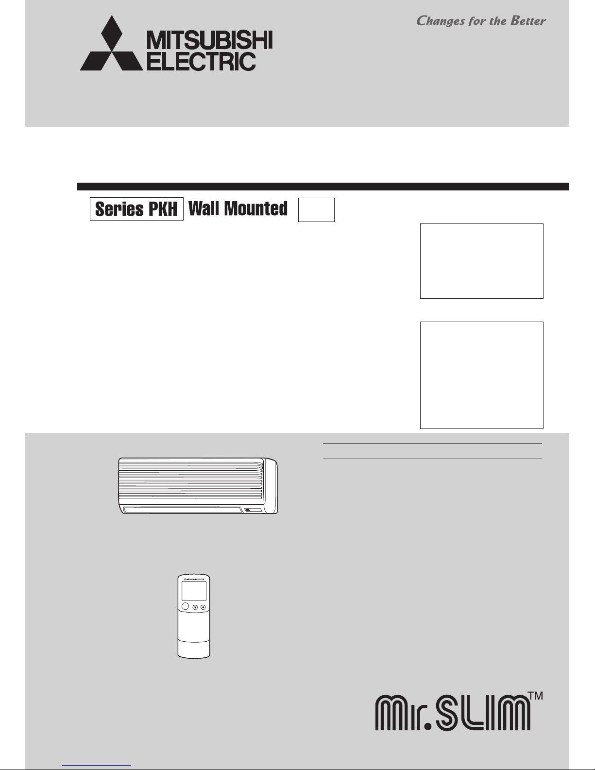
Indoor unit
ON/OFF
Remote controller
•
This manual does not cover the
following outdoor units. When
servicing them, please refer to
the following service manual
and this manual in a set.
[Service Ref.]
PUH-2VKA2
(OC128 REVISED EDITION-A)
PUH-2AKA1·TH-A (OC156)
PUH-2NKA1 (OC145)
Indoor unit
[ Model names ] [ Service Ref. ]
PKH-2GKLA
PKH-2GKLA
No. OC231
REVISED EDITION-A
October 2012
Revision :
•
The indicated No. of
CORNER COVER (page
65) has been corrected in
REVISED EDITION-A.
• Some descriptions have been
modified.
R22
• Please void OC231.

2 33
1 PART NAMES AND FUNCTIONS
● Indoor Unit
Air intake
Air intake grille
Filter
Air outlet
Guide vane
Auto vane
Use the specied refrigerant only
Never use any refrigerant other than that specied.
Doing so may cause a burst, an explosion, or re when the unit is being used, serviced, or disposed of.
Correct refrigerant is specied in the manuals and on the spec labels provided with our products.
We will not be held responsible for mechanical failure, system malfunction, unit breakdown or accidents caused
by failure to follow the instructions.
OC231A
ON/OFF
RESET
MODE FAN
VANE
TEMP.
START
STOP
HR.
MIN.
ON/OFF
CHECK
ADDRESS
UNIT No.
FUNCTION No.
SELECTION No.
AM
PM
RESET
AM
PM
TEST RUN
FUNCTION
°C
MODE FAN
VANE
TEMP.
START
STOP
HR.
MIN.
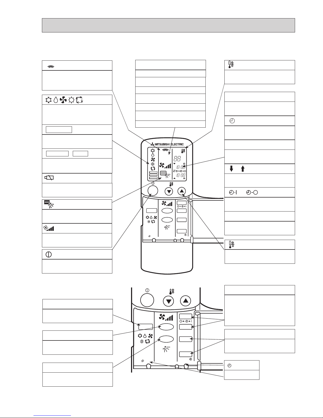
● Wireless remote controller
● When cover is open.
display
Displays when batteries are dead.
display
Lights up when function are set.
display
The unit is turned ON and OFF alternately
each time the button is pressed.
MODE SELECT button
Used to switch the operation mode between
cooling ,drying ,blowing ,heating and auto
mode.
FAN SPEED SELECT button
Used to change the fan speed.
VANE CONTROL button
Used to change the airflow direction.
HR. and MIN.buttons
Buttons used to set the “hour and minute” of
the current time and timer settings.
● When cover is open.
display
OPERATION MODE display
Operation mode display indicates which
operation mode is in effect.
display
The vertical direction of airflow is indicated.
display
FAN SPEED display indicates which fan speed
has been selected.
TEMP. button
SET TEMPERATURE button sets any desired
room temperature.
display
SET TEMP. display indicates desired temperature set.
CLOCK display
Displays the current time.
“ ”display
Flashes when the current time is displayed.
TIMER display
Displays when in timer operation or when setting timer.
“ ” “ ” display
Displays the order of timer operation.
“ ” “ ” display
Displays whether timer is on or off.
“ ” “ ” display
Displays when the current time and the timer
time can be changed.
▼
▼
TIMER CONTROL buttons
STOP (OFF timer): when this switch is set, the
air conditioner will be automatically stopped at
the preset time.
START (ON timer): when this switch is set, the
air conditioner will be automatically started at
the preset time.
• TEST RUN • CHECK display
CHECK&TEST RUN display indicates that the
unit is being checked or test-run.
• FUNCTION
SELECTION NO. display
Displays the selection number.
UNIT NO. display
Displays the number of unit.
FUNCTION NO. display
Displays the mode.
ADDRESS display
Displays the refrigerant address.
display
Lights up while transmission to the indoor unit
is mode using switches.
RESET button
button
OC231A
4 55
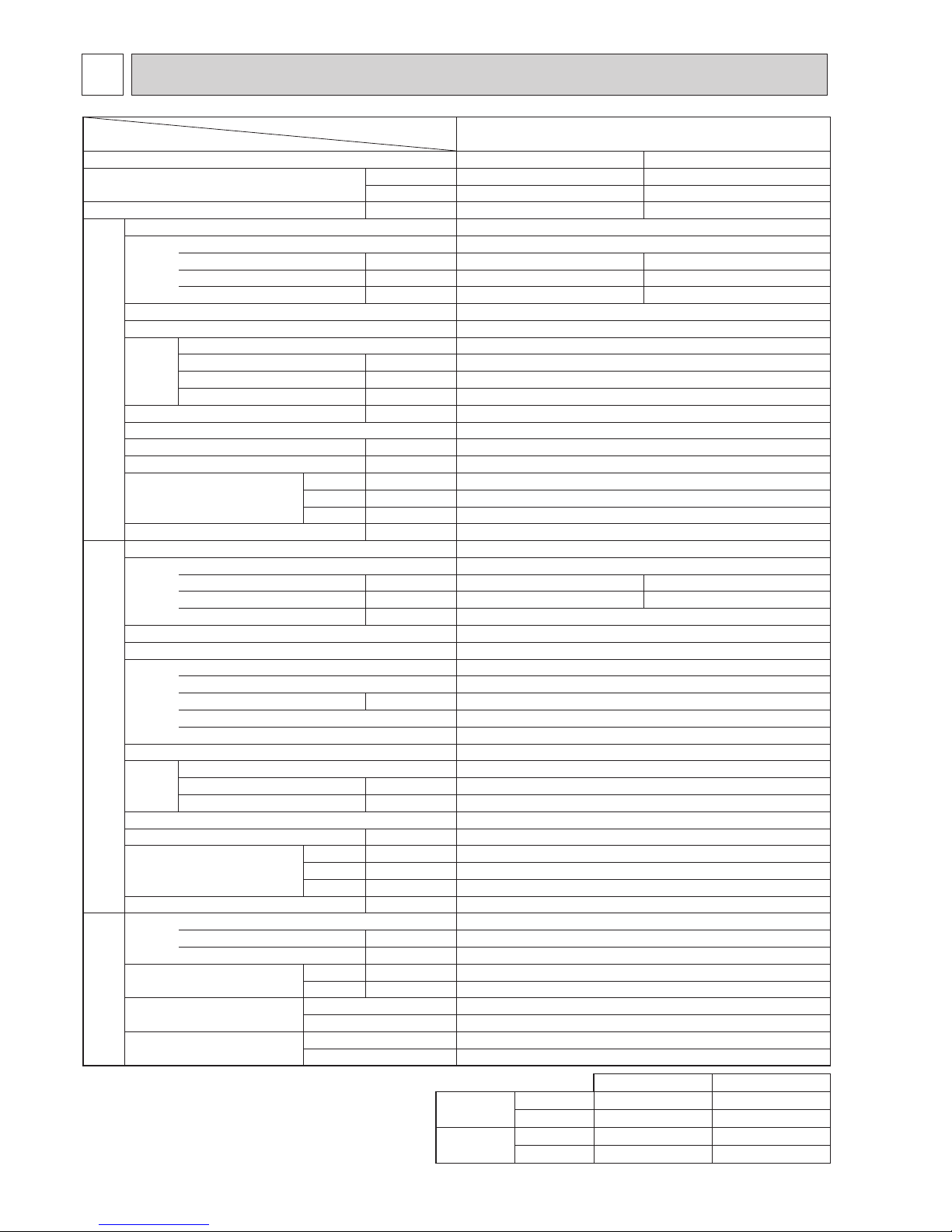
2
SPECIFICATIONS
Item
Function
Capacity
Total input
Service Ref.
Power supply(phase,cycle,voltage)
Input
Running current
Starting current
External finish
Heat exchanger
Fan Fan(drive) × No.
Fan motor output
Airflow(Low-High)
External static pressure
Booster heater
Operation control & Thermostat
Noise level(Low-High)
Unit drain pipe O.D.
Dimensions
Weight
Service Ref.
Power supply (phase, cycle, voltage)
Input
Running current
Starting current
External finish
Refrigerant control
Compressor
Model
Motor output
Starter type
Protection devices
Heat exchanger
Fan Fan(drive)×No.
Fan motor output
Airflow
Defrost method
Noise level
Dimensions
Weight
Refrigerant
Charge
Oil<Model>
Pipe size O.D.
Connection method
Between the indoor & outdoor unit
Service Ref.
W
D
H
W
D
H
Liquid (in.)
Gas (in.)
Indoor side
Outdoor side
Height difference
Piping length
INDOOR UNITOUTDOOR UNIT
REFRIGERANT PIPING
W
Btu/h
kW
kW
A
A
kW
m3/7<CFM>
Pa(mmAq)
kW
(in.)
(in.)
(in.)
(in.)
kg(lbs)
kW
A
A
kW
kW
m3/7<CFM>
(in.)
(in.)
(in.)
kg(lbs)
kg(lbs)
L
PKH-2GKLA
Cooling
5,500
18,800
2.27
0.07
0.33
0.40
2.20
9.86
Heating
6,250
21,300
2.29
0.07
0.33
0.40
2.22
9.95
PKH-2GKLA
Single, 50Hz, 220-240V
Munsell 0.70Y 8.59/0.97
Plate fin coil
Line flow(direct) × 1
0.030
9-12 (318-424)
0(direct blow)
-
Remote controller & built-in
36-43
20 (13/16)
990 (39)
235 (9-1/4)
340 (13-3/8)
16(35)
PUH-2VKA2
Single, 50Hz, 220-240V
45
Munsell 5Y 7/1
Capillary tube
Hermetic
NH38VMD
1.7
Line start
Internal thermostat,HP switch
Plate fin coil
Propeller (direct) × 1
0.065
45(1,590)
Reverse cycle
49
870(34-1/4)
295+24(11-5/8 add 1)
650(25-5/8)
64(141)
R-22
2.2(4.9)
1.2<MS-32>
9.52(3/8)
15.88(5/8)
Flared
Flared
Max. 40m
Max. 40m
Cooling
Heating
Upper limit
Lower limit
Upper limit
Lower limit
Indoor
D.B. 35, W.B. 22.5
D.B. 21, W.B. 15.5
D.B. 27
D.B. 20
Outdoor
D.B. 46
D.B. -5
D.B. 21, W.B. 15.5
D.B. -8.5, W.B. -9.5
2. Guaranteed operating range
Note1. Rating Conditions (JIS B 8616)
Cooling : Indoor : D.B. 27°C (80°F), W.B. 19°C (66°F)
Outdoor : D.B. 35°C (95°F), W.B. 24°C (75°F)
Heating : Indoor : D.B. 20°C (68°F)
Outdoor : D.B. 7°C (45°F), W.B. 6°C (43°F)
OC231A
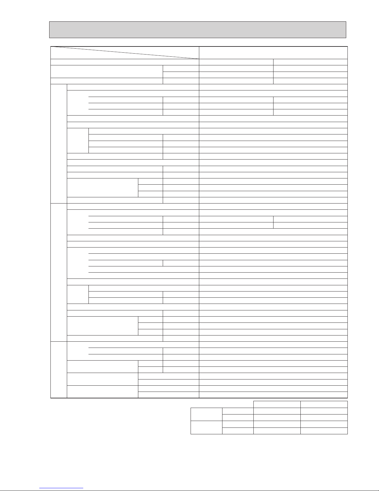
Item
Function
Capacity
Total input
Service Ref.
Power supply(phase,cycle,voltage)
Input
Running current
Starting current
External finish
Heat exchanger
Fan Fan(drive) × No.
Fan motor output
Airflow(Low-High)
External static pressure
Booster heater
Operation control & Thermostat
Noise level(Low-High)
Unit drain pipe O.D.
Dimensions
Weight
Service Ref.
Power supply (phase, cycle, voltage)
Input
Running current
Starting current
External finish
Refrigerant control
Compressor
Model
Motor output
Starter type
Protection devices
Heat exchanger
Fan Fan(drive)×No.
Fan motor output
Airflow
Defrost method
Noise level
Dimensions
Weight
Refrigerant
Charge
Oil<Model>
Pipe size O.D.
Connection method
Between the indoor & outdoor unit
Service Ref.
W
D
H
W
D
H
Liquid (in.)
Gas (in.)
Indoor side
Outdoor side
Height difference
Piping length
INDOOR UNITOUTDOOR UNIT
REFRIGERANT PIPING
W
Btu/h
kW
kW
A
A
kW
m3/7<CFM>
Pa(mmAq)
kW
(in.)
(in.)
(in.)
(in.)
kg(lbs)
kW
A
A
kW
kW
m3/7<CFM>
(in.)
(in.)
(in.)
kg(lbs)
kg(lbs)
L
PKH-2GKLA
Cooling
5,400
18,400
2.25
0.07
0.33
0.40
2.18
9.77
Heating
6,100
20,800
2.26
0.07
0.33
0.40
2.19
9.81
PKH-2GKLA
Single, 50Hz, 240V
Munsell 0.70Y 8.59/0.97
Plate fin coil
Line flow(direct) × 1
0.030
9-12 (318-424)
0(direct blow)
-
Remote controller & built-in
36-43
20 (13/16)
990 (39)
235 (9-1/4)
340 (13-3/8)
16(35)
PUH-2AKA1.TH-A
Single, 50Hz, 240V
45
Munsell 5Y 7/1
Capillary tube
Hermetic
NH38AMDT
1.7
Line start
Internal thermostat,High-pressure switch
Plate fin coil
Propeller (direct) × 1
0.065
45(1,590)
Reverse cycle
49
870(34-1/4)
295+24(11-5/8 add 1)
650(25-5/8)
64(141)
R-22
2.7(6.0)
1.2<MS-32>
9.52(3/8)
15.88(5/8)
Flared
Flared
Max. 40m
Max. 40m
Cooling
Heating
Upper limit
Lower limit
Upper limit
Lower limit
Indoor
D.B. 35, W.B. 22.5
D.B. 21, W.B. 15.5
D.B. 27
D.B. 20
Outdoor
D.B. 46
D.B. -5
D.B. 21, W.B. 15.5
D.B. -8.5, W.B. -9.5
2. Guaranteed operating range
Note1. Rating Conditions (JIS B 8616)
Cooling : Indoor : D.B. 27°C (80°F), W.B. 19°C (66°F)
Outdoor : D.B. 35°C (95°F), W.B. 24°C (75°F)
Heating : Indoor : D.B. 20°C (68°F)
Outdoor : D.B. 7°C (45°F), W.B. 6°C (43°F)
OC231A
6 77
Item
Function
Capacity
Total input
Service Ref.
Power supply(phase,cycle,voltage)
Input
Running current
Starting current
External finish
Heat exchanger
Fan Fan(drive) × No.
Fan motor output
Airflow(Low-High)
External static pressure
Booster heater
Operation control & Thermostat
Noise level(Low-High)
Unit drain pipe O.D.
Dimensions
Weight
Service Ref.
Power supply (phase, cycle, voltage)
Input
Running current
Starting current
External finish
Refrigerant control
Compressor
Model
Motor output
Starter type
Protection devices
Heat exchanger
Fan Fan(drive)×No.
Fan motor output
Airflow
Defrost method
Noise level
Dimensions
Weight
Refrigerant
Charge
Oil<Model>
Pipe size O.D.
Connection method
Between the indoor & outdoor unit
Service Ref.
W
D
H
W
D
H
Liquid (in.)
Gas (in.)
Indoor side
Outdoor side
Height difference
Piping length
INDOOR UNITOUTDOOR UNIT
REFRIGERANT PIPING
W
Btu/h
kW
kW
A
A
kW
m3/7<CFM>
Pa(mmAq)
kW
(in.)
(in.)
(in.)
(in.)
kg(lbs)
kW
A
A
kW
kW
m3/7<CFM>
(in.)
(in.)
(in.)
kg(lbs)
kg(lbs)
L
PKH-2GKLA
CoolingT1/T2
5,800/4,800
19,800/16,400
2.48/2.90
0.07
0.33
0.40
2.41/2.83
11.07/12.99
HeatingT2
6,250
21,300
2.52
0.07
0.33
0.40
2.45
11.2
PKH-2GKLA
Single, 60Hz, 220V
Munsell 0.70Y 8.59/0.97
Plate fin coil
Line flow(direct) × 1
0.030
9-12 (318-424)
0(direct blow)
-
Remote controller & built-in
36-43
20 (13/16)
990 (39)
235 (9-1/4)
340 (13-3/8)
16(35)
PUH-2NKA1
Single, 60Hz, 220V
54
Munsell 5Y 7/1
Capillary tube
Hermetic
NHJ33NBD
1.5
Line start
Internal thermostat,High-pressure switch
Plate fin coil
Propeller (direct) × 1
0.065
45(1,590)
Reverse cycle
49
870(34-1/4)
295+24(11-5/8 add 1)
650(25-5/8)
66.5(147)
R-22
2.7(6.0)
1.2<MS-32>
9.52(3/8)
15.88(5/8)
Flared
Flared
Max. 40m
Max. 40m
Cooling
Heating
Upper limit
Lower limit
Upper limit
Lower limit
Indoor
D.B. 35, W.B. 22.5
D.B. 21, W.B. 15.5
D.B. 27
D.B. 20
Outdoor
D.B. 52
D.B. -5
D.B. 21, W.B. 15.5
D.B. -8.5, W.B. -9.5
2. Guaranteed operating range
Note1. *1.Rating Conditions (JIS B 8616)
Cooling : Indoor : D.B. 27°C (80°F), W.B. 19°C (66°F)
Outdoor : D.B. 35°C (95°F), W.B. 24°C (75°F)
*2.Rating Conditions (SSA385)
Cooling : Indoor : D.B. 29°C , W.B. 19°C
Outdoor : D.B. 46°C
Heating : Indoor : D.B. 21°C
Outdoor : D.B. 7°C , W.B. 6°C
OC231A
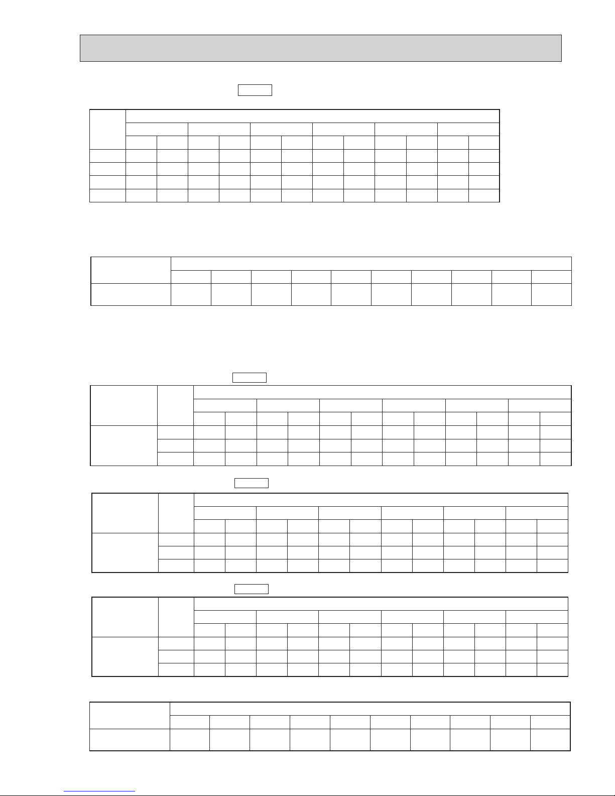
3 DATA
50Hz
(Outdoor unit : PUH-2VKA2)
1. PERFORMANCE DATA
1) COOLING CAPACITY<1>
PKH-2GKLA
Outdoor intake air D.B.(°C)
20 25 30
Indoor
Intake air
D.B.(°C)
Indoor
Intake air
W.B.(°C)
20
20
20
22
22
22
24
24
24
24
26
26
26
26
27
27
27
27
28
28
28
28
30
30
30
30
32
32
32
32
16
18
20
16
18
20
16
18
20
22
16
18
20
22
16
18
20
22
16
18
20
22
16
18
20
22
16
18
20
22
CA
5549
5908
6271
5549
5908
6271
5549
5908
6271
6638
5549
5908
6271
6638
5549
5908
6271
6638
5549
5908
6271
6638
5549
5908
6271
6638
5549
5908
6271
6638
SHC(W)
3274
2777
2195
3718
3249
2696
4161
3722
3198
2589
4605
4195
3700
3120
4827
4431
3951
3385
5049
4667
4202
3651
5493
5140
4703
4182
5549
5612
5205
4713
SHF
0.59
0.47
0.35
0.67
0.55
0.43
0.75
0.63
0.51
0.39
0.83
0.71
0.59
0.47
0.87
0.75
0.63
0.51
0.91
0.79
0.67
0.55
0.99
0.87
0.75
0.63
1.00
0.95
0.83
0.71
SHF
0.59
0.47
0.35
0.67
0.55
0.43
0.75
0.63
0.51
0.39
0.83
0.71
0.59
0.47
0.87
0.75
0.63
0.51
0.91
0.79
0.67
0.55
0.99
0.87
0.75
0.63
1.00
0.95
0.83
0.71
SHF
0.59
0.47
0.35
0.67
0.55
0.43
0.75
0.63
0.51
0.39
0.83
0.71
0.59
0.47
0.87
0.75
0.63
0.51
0.91
0.79
0.67
0.55
0.99
0.87
0.75
0.63
1.00
0.95
0.83
0.71
P.C.
1.82
1.86
1.89
1.82
1.86
1.89
1.82
1.86
1.89
1.93
1.82
1.86
1.89
1.93
1.82
1.86
1.89
1.93
1.82
1.86
1.89
1.93
1.82
1.86
1.89
1.93
1.82
1.86
1.89
1.93
CA
5397
5752
6124
5397
5752
6124
5397
5752
6124
6511
5397
5752
6124
6511
5397
5752
6124
6511
5397
5752
6124
6511
5397
5752
6124
6511
5397
5752
6124
6511
SHC(W)
3184
2704
2143
3616
3164
2633
4048
3624
3123
2539
4479
4084
3613
3060
4695
4314
3858
3320
4911
4544
4103
3581
5343
5004
4593
4102
5397
5465
5083
4623
P.C.
1.90
1.94
1.97
1.90
1.94
1.97
1.90
1.94
1.97
2.01
1.90
1.94
1.97
2.01
1.90
1.94
1.97
2.01
1.90
1.94
1.97
2.01
1.90
1.94
1.97
2.01
1.90
1.94
1.97
2.01
CA
5198
5543
5905
5198
5543
5905
5198
5543
5905
6285
5198
5543
5905
6285
5198
5543
5905
6285
5198
5543
5905
6285
5198
5543
5905
6285
5198
5543
5905
6285
SHC(W)
3067
2605
2067
3483
3049
2539
3899
3492
3012
2451
4315
3935
3484
2954
4523
4157
3720
3205
4731
4379
3956
3457
5146
4822
4429
3960
5198
5266
4901
4462
P.C.
2.04
2.09
2.13
2.04
2.09
2.13
2.04
2.09
2.13
2.18
2.04
2.09
2.13
2.18
2.04
2.09
2.13
2.18
2.04
2.09
2.13
2.18
2.04
2.09
2.13
2.18
2.04
2.09
2.13
2.18
CA : Capacity (W) SHC(W) : Sensible heat capacity
P.C. : Power consumption (kW) SHF : Sensible heat factor
OC231A
8 9
9
COOLING CAPACITY<2>
PKH-2GKLA
Outdoor intake air D.B.(°C)
35 40 45
Indoor
Intake air
D.B.(°C)
Indoor
Intake air
W.B.(°C)
20
20
20
22
22
22
24
24
24
24
26
26
26
26
27
27
27
27
28
28
28
28
30
30
30
30
32
32
32
32
16
18
20
16
18
20
16
18
20
22
16
18
20
22
16
18
20
22
16
18
20
22
16
18
20
22
16
18
20
22
CA
4988
5323
5677
4988
5323
5677
4988
5323
5677
6050
4988
5323
5677
6050
4988
5323
5677
6050
4988
5323
5677
6050
4988
5323
5677
6050
4988
5323
5677
6050
SHC(W)
2943
2502
1987
3342
2928
2411
3741
3353
2895
2360
4140
3779
3349
2844
4339
3992
3577
3086
4539
4205
3804
3328
4938
4631
4258
3812
4988
5057
4712
4296
P.C.
2.19
2.24
2.30
2.19
2.24
2.30
2.19
2.24
2.30
2.35
2.19
2.24
2.30
2.35
2.19
2.24
2.30
2.35
2.19
2.24
2.30
2.35
2.19
2.24
2.30
2.35
2.19
2.24
2.30
2.35
CA
4765
5093
5440
4765
5093
5440
4765
5093
5440
5806
4765
5093
5440
5806
4765
5093
5440
5806
4765
5093
5440
5806
4765
5093
5440
5806
4765
5093
5440
5806
SHC(W)
2811
2394
1904
3192
2801
2339
3574
3208
2774
2264
3955
3616
3209
2729
4145
3820
3427
2961
4336
4023
3645
3193
4717
4431
4080
3658
4765
4838
4515
4122
P.C.
2.34
2.40
2.46
2.34
2.40
2.46
2.34
2.40
2.46
2.53
2.34
2.40
2.46
2.53
2.34
2.40
2.46
2.53
2.34
2.40
2.46
2.53
2.34
2.40
2.46
2.53
2.34
2.40
2.46
2.53
CA
4530
4852
5193
4530
4852
5193
4530
4852
5193
5552
4530
4852
5193
5552
4530
4852
5193
5552
4530
4852
5193
5552
4530
4852
5193
5552
4530
4852
5193
5552
SHC(W)
2673
2281
1818
3035
2669
2233
3397
3057
2648
2165
3760
3445
3064
2610
3941
3639
3272
2832
4122
3833
3479
3054
4484
4221
3895
3498
4530
4610
4310
3942
P.C.
2.49
2.55
2.63
2.49
2.55
2.63
2.49
2.55
2.63
2.71
2.49
2.55
2.63
2.71
2.49
2.55
2.63
2.71
2.49
2.55
2.63
2.71
2.49
2.55
2.63
2.71
2.49
2.55
2.63
2.71
SHF
0.59
0.47
0.35
0.67
0.55
0.43
0.75
0.63
0.51
0.39
0.83
0.71
0.59
0.47
0.87
0.75
0.63
0.51
0.91
0.79
0.67
0.55
0.99
0.87
0.75
0.63
1.00
0.95
0.83
0.71
SHF
0.59
0.47
0.35
0.67
0.55
0.43
0.75
0.63
0.51
0.39
0.83
0.71
0.59
0.47
0.87
0.75
0.63
0.51
0.91
0.79
0.67
0.55
0.99
0.87
0.75
0.63
1.00
0.95
0.83
0.71
SHF
0.59
0.47
0.35
0.67
0.55
0.43
0.75
0.63
0.51
0.39
0.83
0.71
0.59
0.47
0.87
0.75
0.63
0.51
0.91
0.79
0.67
0.55
0.99
0.87
0.75
0.63
1.00
0.95
0.83
0.71
CA : Capacity (W) SHC(W) : Sensible heat capacity
P.C. : Power consumption (kW) SHF : Sensible heat factor
50Hz
(Outdoor unit : PUH-2VKA2)
OC231A
9
COOLING CAPACITY<3>
PKH-2GKLA
Outdoor intake air D.B.(°C)
20 25 30
Indoor
Intake air
D.B.(°C)
Indoor
Intake air
W.B.(°C)
20
20
20
22
22
22
24
24
24
24
26
26
26
26
27
27
27
27
28
28
28
28
30
30
30
30
32
32
32
32
16
18
20
16
18
20
16
18
20
22
16
18
20
22
16
18
20
22
16
18
20
22
16
18
20
22
16
18
20
22
CA
5448
5800
6157
5448
5800
6157
5448
5800
6157
6517
5448
5800
6157
6517
5448
5800
6157
6517
5448
5800
6157
6517
5448
5800
6157
6517
5448
5800
6157
6517
SHC(W)
3269
2784
2216
3704
3248
2709
4140
3712
3202
2607
4576
4176
3694
3128
4794
4408
3940
3389
5012
4640
4187
3650
5448
5104
4679
4171
5448
5568
5172
4692
SHF
0.60
0.48
0.36
0.68
0.56
0.44
0.76
0.64
0.52
0.40
0.84
0.72
0.60
0.48
0.88
0.76
0.64
0.52
0.92
0.80
0.68
0.56
1.00
0.88
0.76
0.64
1.00
0.96
0.84
0.72
SHF
0.60
0.48
0.36
0.68
0.56
0.44
0.76
0.64
0.52
0.40
0.84
0.72
0.60
0.48
0.88
0.76
0.64
0.52
0.92
0.80
0.68
0.56
1.00
0.88
0.76
0.64
1.00
0.96
0.84
0.72
SHF
0.60
0.48
0.36
0.68
0.56
0.44
0.76
0.64
0.52
0.40
0.84
0.72
0.60
0.48
0.88
0.76
0.64
0.52
0.92
0.80
0.68
0.56
1.00
0.88
0.76
0.64
1.00
0.96
0.84
0.72
P.C.
1.80
1.84
1.87
1.80
1.84
1.87
1.80
1.84
1.87
1.91
1.80
1.84
1.87
1.91
1.80
1.84
1.87
1.91
1.80
1.84
1.87
1.91
1.80
1.84
1.87
1.91
1.80
1.84
1.87
1.91
CA
5299
5648
6012
5299
5648
6012
5299
5648
6012
6392
5299
5648
6012
6392
5299
5648
6012
6392
5299
5648
6012
6392
5299
5648
6012
6392
5299
5648
6012
6392
SHC(W)
3179
2711
2164
3603
3163
2645
4027
3615
3126
2557
4451
4066
3607
3068
4663
4292
3848
3324
4875
4518
4008
3580
5299
4970
4569
4091
5299
5422
5050
4602
P.C.
1.88
1.92
1.96
1.88
1.92
1.96
1.88
1.92
1.96
2.00
1.88
1.92
1.96
2.00
1.88
1.92
1.96
2.00
1.88
1.92
1.96
2.00
1.88
1.92
1.96
2.00
1.88
1.92
1.96
2.00
CA
5104
5442
5798
5104
5442
5798
5104
5442
5798
6171
5104
5442
5798
6171
5104
5442
5798
6171
5104
5442
5798
6171
5104
5442
5798
6171
5104
5442
5798
6171
SHC(W)
3062
2612
2087
3471
3048
2551
3879
3483
3015
2468
4287
3918
3479
2962
4491
4136
3710
3209
4696
4354
3942
3456
5104
4789
4406
3949
5104
5224
4870
4443
P.C.
2.02
2.07
2.12
2.02
2.07
2.12
2.02
2.07
2.12
2.16
2.02
2.07
2.12
2.16
2.02
2.07
2.12
2.16
2.02
2.07
2.12
2.16
2.02
2.07
2.12
2.16
2.02
2.07
2.12
2.16
CA : Capacity (W) SHC(W) : Sensible heat capacity
P.C. : Power consumption (kW) SHF : Sensible heat factor
50Hz
(Outdoor unit : PUH-2AKA1·TH-A)
OC231A

10 11
11
COOLING CAPACITY<4>
PKH-2GKLA
Outdoor intake air D.B.(°C)
35 40 45
Indoor
Intake air
D.B.(°C)
Indoor
Intake air
W.B.(°C)
20
20
20
22
22
22
24
24
24
24
26
26
26
26
27
27
27
27
28
28
28
28
30
30
30
30
32
32
32
32
16
18
20
16
18
20
16
18
20
22
16
18
20
22
16
18
20
22
16
18
20
22
16
18
20
22
16
18
20
22
CA
4897
5226
5574
4897
5226
5574
4897
5226
5574
5940
4897
5226
5574
5940
4897
5226
5574
5940
4897
5226
5574
5940
4897
5226
5574
5940
4897
5226
5574
5940
SHC(W)
2938
2509
2007
3330
2927
2452
3772
3345
2898
2376
4114
3763
3344
2851
4309
3972
3567
3089
4505
4181
3790
3327
4897
4599
4236
3802
4897
5017
4682
4277
P.C.
2.17
2.22
2.28
2.17
2.22
2.28
2.17
2.22
2.28
2.33
2.17
2.22
2.28
2.33
2.17
2.22
2.28
2.33
2.17
2.22
2.28
2.33
2.17
2.22
2.28
2.33
2.17
2.22
2.28
2.33
CA
4678
5000
5341
4678
5000
5341
4678
5000
5341
5700
4678
5000
5341
5700
4678
5000
5341
5700
4678
5000
5341
5700
4678
5000
5341
5700
4678
5000
5341
5700
SHC(W)
2807
2400
1923
3181
2800
2350
3555
3200
2777
2280
3930
3600
3205
2736
4117
3800
3418
2964
4304
4000
3632
3192
4678
4400
4059
3648
4678
4800
4486
4104
P.C.
2.32
2.38
2.44
2.32
2.38
2.44
2.32
2.38
2.44
2.51
2.32
2.38
2.44
2.51
2.32
2.38
2.44
2.51
2.32
2.38
2.44
2.51
2.32
2.38
2.44
2.51
2.32
2.38
2.44
2.51
CA
4447
4764
5099
4447
4764
5099
4447
4764
5099
5451
4447
4764
5099
5451
4447
4764
5099
5451
4447
4764
5099
5451
4447
4764
5099
5451
4447
4764
5099
5451
SHC(W)
2668
2287
1836
3024
2668
2243
3380
3049
2651
2181
3736
3430
3059
2617
3914
3621
3263
2835
4092
3811
3467
3053
4447
4192
3875
3489
4447
4573
4283
3925
P.C.
2.46
2.53
2.60
2.46
2.53
2.60
2.46
2.53
2.60
2.69
2.46
2.53
2.60
2.69
2.46
2.53
2.60
2.69
2.46
2.53
2.60
2.69
2.46
2.53
2.60
2.69
2.46
2.53
2.60
2.69
SHF
0.60
0.48
0.36
0.68
0.56
0.44
0.76
0.64
0.52
0.40
0.84
0.72
0.60
0.48
0.88
0.76
0.64
0.52
0.92
0.80
0.68
0.56
1.00
0.88
0.76
0.64
1.00
0.96
0.84
0.72
SHF
0.60
0.48
0.36
0.68
0.56
0.44
0.76
0.64
0.52
0.40
0.84
0.72
0.60
0.48
0.88
0.76
0.64
0.52
0.92
0.80
0.68
0.56
1.00
0.88
0.76
0.64
1.00
0.96
0.84
0.72
SHF
0.60
0.48
0.36
0.68
0.56
0.44
0.76
0.64
0.52
0.40
0.84
0.72
0.60
0.48
0.88
0.76
0.64
0.52
0.92
0.80
0.68
0.56
1.00
0.88
0.76
0.64
1.00
0.96
0.84
0.72
CA : Capacity (W) SHC(W) : Sensible heat capacity
P.C. : Power consumption (kW) SHF : Sensible heat factor
50Hz
(Outdoor unit : PUH-2AKA1·TH-A)
OC231A
11
COOLING CAPACITY<5>
PKH-2GKLA
16
18
20
22
CA
5,851
6,230
6,613
7,000
P.C.
1.99
2.03
2.07
2.10
CA
5,691
6,066
6,458
6,866
P.C.
2.07
2.11
2.16
2.20
CA
5,482
5,845
6,227
6,628
P.C.
2.23
2.28
2.33
2.38
CA
5,260
5,613
5,987
6,380
P.C.
2.39
2.45
2.51
2.57
CA
5,025
5,371
5,736
6,123
P.C.
2.55
2.62
2.69
2.76
CA
4,777
5,117
5,476
5,855
P.C.
2.72
2.79
2.87
2.97
20 25 30
Indoor
intake
air
W.B.(°C)
35
Outdoor intake air D.B.(°C)
40 45
60Hz
(Outdoor unit : PUH-2NKA1)
Service Ref.
PKH-2GKLA
Refrigerant piping length(one way)
5m 10m 15m 20m 25m 30m 35m 40m 45m 50m
1.00 0.992 0.983
0.978
0.966
0.959
0.950 0.945
— —
Cooling capacity correction factors
15
20
25
CA
4,280
4,098
3,939
P.C.
1.56
1.68
1.79
CA
4,905
4,713
4,521
P.C.
1.73
1.86
1.98
CA
5,591
5,380
5,167
P.C.
1.90
2.05
2.19
CA
6,336
6,100
5,874
P.C.
2.09
2.25
2.41
CA
7,139
6,871
6,643
P.C.
2.28
2.46
2.64
CA
8,000
7,693
7,473
P.C.
2.49
2.68
2.87
-10 -5 0Service Ref.
Indoor
intake
air
D.B.(°C)
PKH-2GKLA
5
Outdoor intake air W.B.(°C)
10 15
2) HEATING CAPACITY
CA : Capacity (W)
P.C. : Power consumption (kW)
Service Ref.
PKH-2GKLA
Refrigerant piping length(one way)
5m 10m 15m 20m 25m 30m 35m 40m 45m 50m
1.00 1.00
1.00 1.00
1.00 1.00 0.998 0.995 — —
Heating capacity correction factors
50Hz
(Outdoor unit : PUH-2VKA2)
15
20
25
CA
4,177
4,000
3,844
P.C.
1.54
1.66
1.76
CA
4,788
4,600
4,413
P.C.
1.70
1.84
1.96
CA
5,457
5,251
5,043
P.C.
1.88
2.02
2.16
CA
6,184
5,953
5,733
P.C.
2.06
2.22
2.38
CA
6,968
6,706
6,483
P.C.
2.25
2.43
2.60
CA
7,808
7,509
7,294
P.C.
2.46
2.64
2.84
-10 -5 0Service Ref.
Indoor
intake
air
D.B.(°C)
PKH-2GKLA
5
Outdoor intake air W.B.(°C)
10 15
HEATING CAPACITY
CA : Capacity (W)
P.C. : Power consumption (kW)
50Hz
(Outdoor unit : PUH-2AKA1·TH-A)
15
20
25
CA
4,314
4,131
3,970
P.C.
1.64
1.76
1.87
CA
4,945
4,750
4,558
P.C.
1.81
1.95
2.08
CA
5,636
5,423
5,208
P.C.
1.99
2.15
2.30
CA
6,387
6,149
5,921
P.C.
2.19
2.36
2.52
CA
7,197
6,926
6,696
P.C.
2.39
2.58
2.76
CA
8,064
7,755
7,533
P.C.
2.61
2.81
3.01
-10 -5 0Service Ref.
Indoor
intake
air
D.B.(°C)
PKH-2GKLA
5
Outdoor intake air W.B.(°C)
10 15
HEATING CAPACITY
CA : Capacity (W)
P.C. : Power consumption (kW)
60Hz
(Outdoor unit : PUH-2NKA1)
CA : Capacity(W)
P.C. : Power consumption (kW)
OC231A
12 13
13
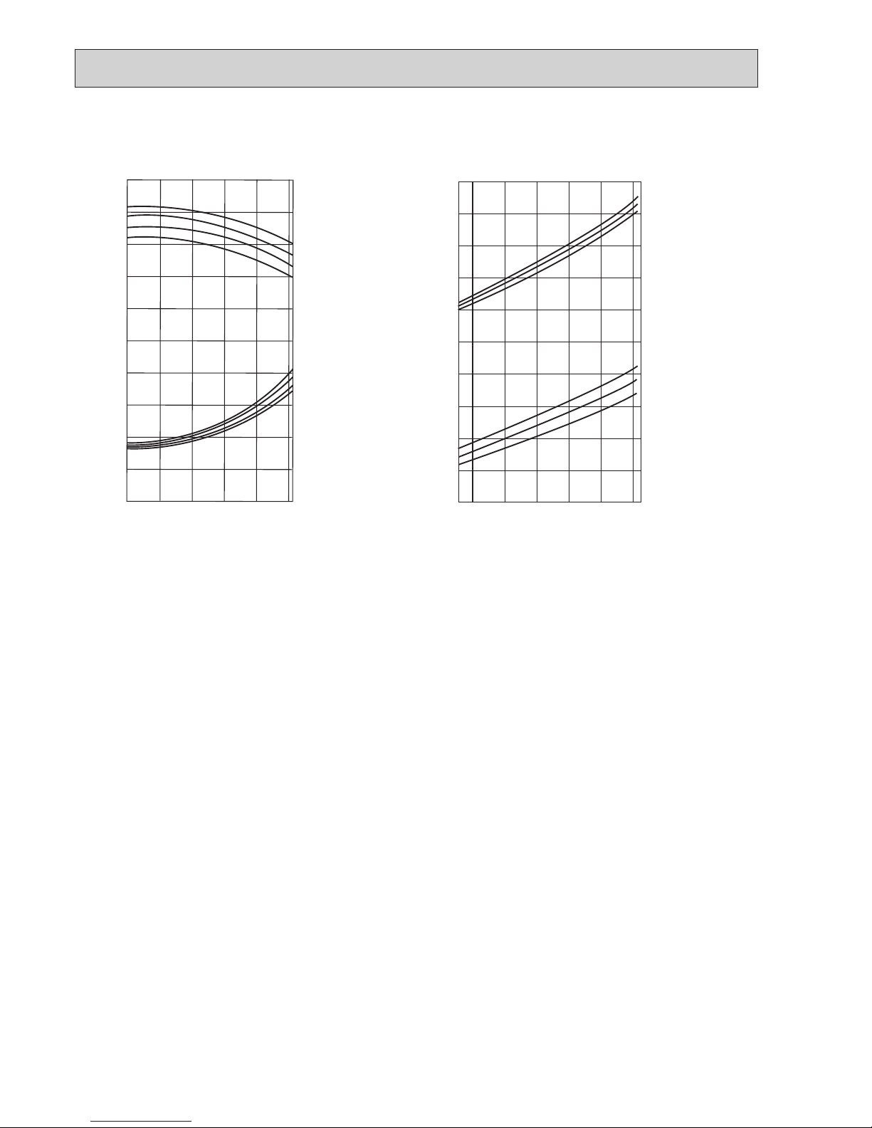
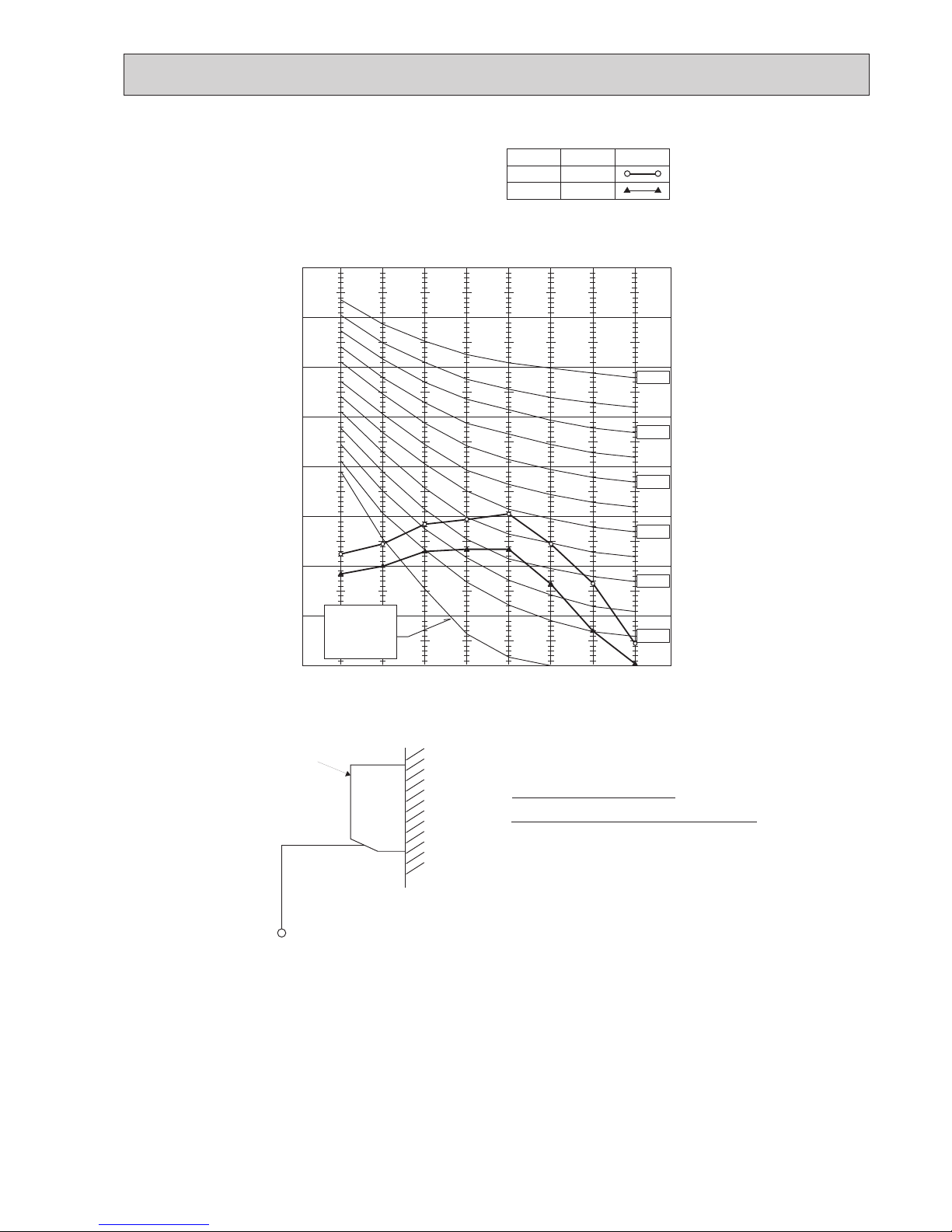
2. PERFORMANCE CURVE
1.4
1.2
1.0
0.8
0.6
1.4
1.2
1.0
0.8
0.6
0.4
-12-10 -5 0 5 10 15
OUTDOOR W.B. (°C)
INDOOR D.B. (°C)
INDOOR D.B. (°C)
15
20
25
25
20
15
TOTAL INPUT (RATIO) CAPACITY (RATIO)
Heating
1.4
1.2
1.0
0.8
0.6
1.4
1.2
1.0
0.8
0.6
0.4
-5 5 15 25 35 46
OUTDOOR D.B.(°C)
TOTAL INPUT (RATIO) CAPACITY (RATIO)
INDOOR W.B.(°C)
INDOOR W.B.(°C)
22
20
18
16
22
20
18
16
Cooling
OC231A
13
Service Ref.
Indoor unit
Outdoor unit
PKH-2GKLA
PUH-2NKA1
Cool
5,800
2.48
0.07
0.33
0.40
2.41
11.07
54
4,650
(5,450)
1.48
(2.28)
0.07
<0.87>
0.33
<3.66>
0.40
<3.73>
Heat
1.41
6.60
33
6,250
2.52
0.07
0.33
0.40
Cool
4,800
2.90
0.07
0.33
0.40
2.83
12.99
54
Heat
2.45
11.2
54
PKH-2GKLA
PUH-2NKA1
Outdoor
unit
Indoor
unit
Mode
Capacity(W)
Total Input(kW)
Input(kW)
Current(A)
Starting current(A)
Input(kW)
Current(A)
Starting current(A)
Service Ref.
Indoor unit
Outdoor unit
PKH-1.6GKLH
PKH-1.6GKL
PUH-1.6VKA2
Cool
4,450
1.47
0.07
0.33
0.40
1.40
6.76
32
4,600
(5,330)
1.43
(2.16)
0.07
<0.80>
0.33
<3.50>
0.40
<3.57>
Heat
1.36
6.57
32
6,100
2.26
0.07
0.33
0.40
Cool
5,400
2.25
0.07
0.33
0.40
2.18
9.77
45
Heat
2.19
9.81
45
PKH-2GKLA
PUH-2AKA1·TH-A
Outdoor
unit
Indoor
unit
Mode
Capacity(W)
Total Input(kW)
Input(kW)
Current(A)
Starting current(A)
Input(kW)
Current(A)
Starting current(A)
Indoor unit 240V 50Hz 1phase
Outdoor unit 240V 50Hz 1phase
Indoor unit 220V 60Hz 1phase
Outdoor unit 220V 60Hz 1phase
Service Ref.
Indoor unit
Outdoor unit
PKH-2GKLA
PUH-2VKA2
Cool
5,400
2.19
0.07
0.33
0.40
2.12
9.83
43
6,150
2.21
0.07
0.33
0.40
Heat
2.14
9.93
43
6,250
2.29
0.07
0.33
0.40
Cool
5,500
2.27
0.07
0.33
0.40
2.20
9.86
45
Heat
2.22
9.95
45
PKH-2GKLA
PUH-2VKA2
6,200
2.25
0.07
0.33
0.40
Cool
5,450
2.23
0.07
0.33
0.40
2.16
9.78
44
Heat
2.18
9.87
44
PKH-2GKLA
PUH-2VKA2
Outdoor
unit
Indoor
unit
Mode
Capacity(W)
Total Input(kW)
Input(kW)
Current(A)
Starting current(A)
Input(kW)
Current(A)
Starting current(A)
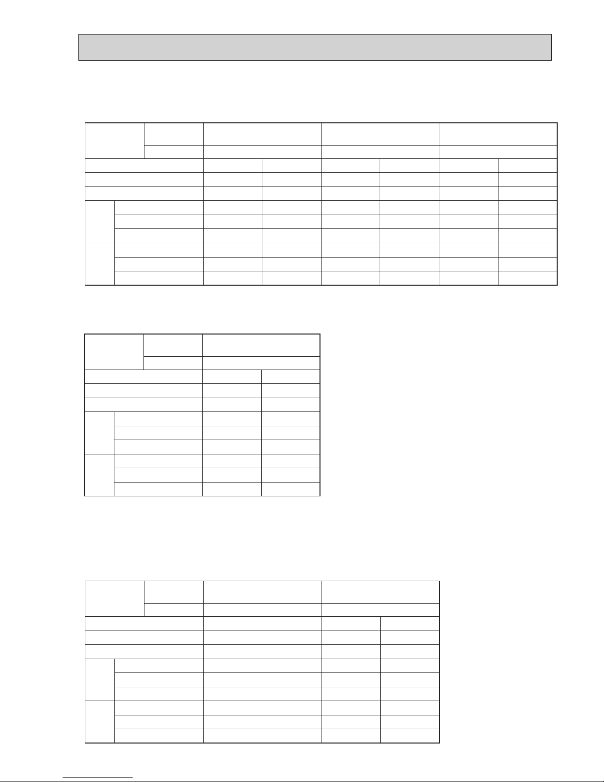
3. ELECTRICAL DATA
Indoor unit 220V 50Hz 1phase, 230V 50Hz 1phase, 230V 50Hz 1phase
Outdoor unit 220V 50Hz 1phase, 230V 50Hz 1phase, 240V 50Hz 1phase
Rating Conditions
(Cooling) : Indoor : D.B. 29°C , W.B. 19°C
Outdoor : D.B. 46°C
(Heating ): Indoor : D.B. 21°C
Outdoor : D.B. 7°C , W.B. 6°C
Rating Conditions ( Cooling)
Indoor : D.B. 27°C , W.B. 19°C
Outdoor : D.B. 35°C
OC231A
14 15
15
Outdoor unit Service Ref.
Service Ref. PKH-2GKLA
PKH-2GKLA
PKH-2GKLA
PKH-2GKLA
CoolingMode
Capacity W
Input
Indoor unit
Service Ref.
Phase,Hz
Volts
Amperes
Phase,Hz
Volts
Amperes
Discharge pressure
Suction pressure
Discharge temperature
Condensing temperature
Suction temperature
Ref.pipe length
Intake air
temperature
Discharge air
temperature
Intake air
temperature
kW
V
A
V
A
5,500
2.27
Heating
6,250
2.29
0.33 0.33
9.86
1.92
(
19.6
)
1.97
(20.1)
2.15
(21.9)
0.44
(
4.5
)
0.39
(3.8)
0.46
(4.7)
87
51
4
5
27
19
11.7
35
24
0.69
0.12
9.95
2.08
(21.2)
0.39
(3.8)
93
54
–2
5
20
15
45.4
7
6
-
-
1,50
240
1, 50
240
PUH-2VKA2
Cooling Heating
5,800
2.48
6,250
2.52
0.33 0.33
11.07 11.20
70 99
51 55
3 –2
5 5
27 21
19 15
11.2 46
35 7
24 6
0.68
-
0.12
-
1,60
1, 60
220
220
PUH-2NKA1
PKH-2GKLA
PKH-2GKLA
1.95
(19.9)
2.08
(21.2)
0.47
(
4.8
)
0.39
(3.8)
Cooling Heating
5,400
2.25
6,100
2.26
0.33 0.33
9.77 9.81
92 95
51 54
4 4
5 5
27 20
19 15
11.9 44
35 7
24 6
0.70
-
0.12
-
1,50
1, 50
240
240
PUH-2AKA1·TH-A
°C
°C
°C
°C
BF
SHF
°C
D.B.
D.B.
W.B.
D.B.
W.B.
°C
°C
°C
m
MPa
(
kg/cm
2
)
MPa
(
kg/cm
2
)
Outdoor
side
Indoor side Refrigerant circuit Electrical circuit Total
Air flow m3/
min
Air speed m/
sec
Coverage range m (ft)
PKH-1.6GKLH
PKH-1.6GKL
PKH-2GKLA
12
5.3
10(32.8)
12
5.3
10(32.8)
Item
Service Ref.
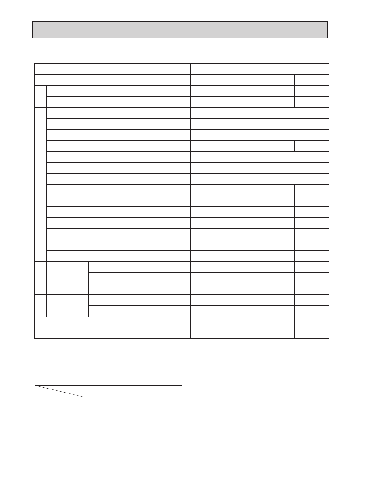
4. STANDARD OPERATION DATA
The unit of pressure has been changed to Mpa on the international system of unit (SI unit system).
The converted score against the traditional unit system can be gotten according to the formula below.
1(Mpa) = 10.2(kg/cm²)
5. OUTLET AIR SPEED AND COVERAGE RANGE
The air coverage range is the value up to the position where the air speed is 0.25m/sec. when air is blown out horizontally from
the unit at the Hi notch position.
The coverage range should be used only as a general guideline since it varies according to the size of the room and the furniture inside the room.
OC231A
15
90
80
70
60
50
40
30
20
10
63 125 250 500 1000 2000 4000 8000
APPROTIMATE
THRESHOLD OF
HEARING FOR
CONTINUOUS
NOISE
NC-60
NC-50
NC-40
NC-30
NC-20
NC-70
OCTAVE BAND SOUND PRESSURE LEVEL, dB re 0.002 MICRO BAR
BAND CENTER FREQUENCIES, Hz
PKH-2GKLA
Hi
NOTCH
Lo
43
SPL(dB)36LINE
6. NOISE CRITERION CURVES
UNIT
WALL
1m
1m
MICROPHONE
Ambient temperature 27
Test conditions are based on JIS Z8731
OC231A
16 17
17
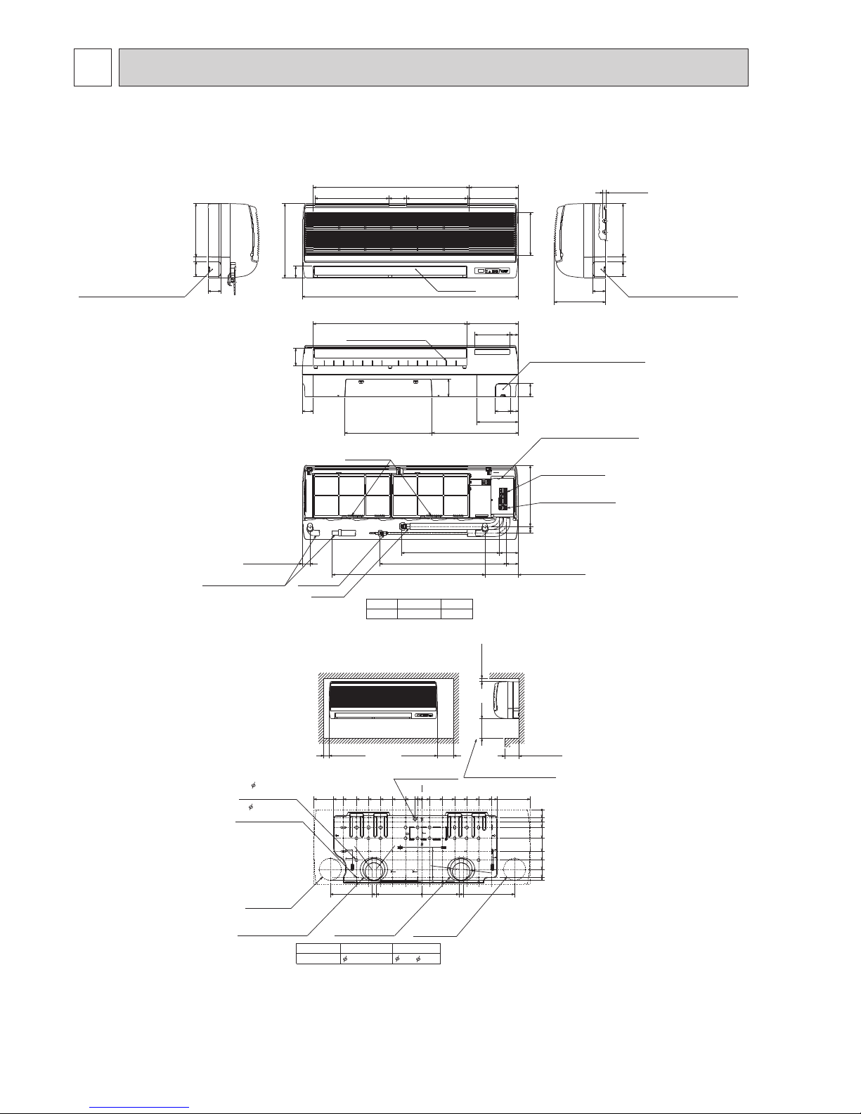
4
OUTLINES AND DIMENSIONS
INDOOR UNIT
PKH-2GKLA
Unit : mm
BYOFF
ONSTAND
HEATCOOL
OFF BY
ON STAND
COOL HEAT
r.SLI
m m
MITSUBISHI ELECTRIC
r.SLI
m m
MITSUBISHI ELECTRIC
Knockout hole for right piping
Refrigerant pipe.Drain pipe.
Wiring hole
21
Right side
Less than 15
70
245
60
235
Auto vane
Front view
Air intake
Air intake
Air intake
Air intake
198
53
340
715 225
340 80 280 233
990
21
Left side
Knockout hole for left piping
Refrigerant pipe.Drain pipe.
Wiring hole.
60
70
245
(Necessary clearance for
Unit installation)
Right side
Allowing clearances
Front view
Less than 130
50 or more 150 or more
180 or more 30 or more
for bolts
Left-rear
piping hole
left-rear piping
R52.5
R52.5
Installation plate
balance point hole
Details of installation plate
49- 5hole
for tapping screw
Knockout hole for
right-rear piping
Right-rear
piping hole
Unit center
14- 14hole
Knockout hole for
425
420
170
190
210
230
0
322
0
35
55
80
130
190
230
272
310
0
3595150
205
260
320
345
495
20
75
135
190
245
300
360
405
495
32
0
*1 Sleeves are available on the market.
*2 This size shows the lower end of through hole.
90~ 10090
Through hole
Sleeve *1
2
Model
R52.5
R52.5
Gas pipe
Liquid pipe
Terminal block for
Terminal block to
outdoor unit
Filter grip
Service panel
(Power supply access)
5/8F
Gas pipe
Liquid pipe
3/8F 2
Model
(Flexible hose total length800)
(Right side piping
installation)
(Left side piping
installation)
Unit drain pipe O.D.20
Front view(to open the grille)
700
581
86
449
54
31 280
35
Knockout hole for under piping
Refrigerant piping.Drain pipe.
Wiring hole
12-Louvers(manual)
Air outlet
Lower side
80
50
395400
190
60
70 35
79
160 40
235
705
power supply
153
*2
OC231A
17
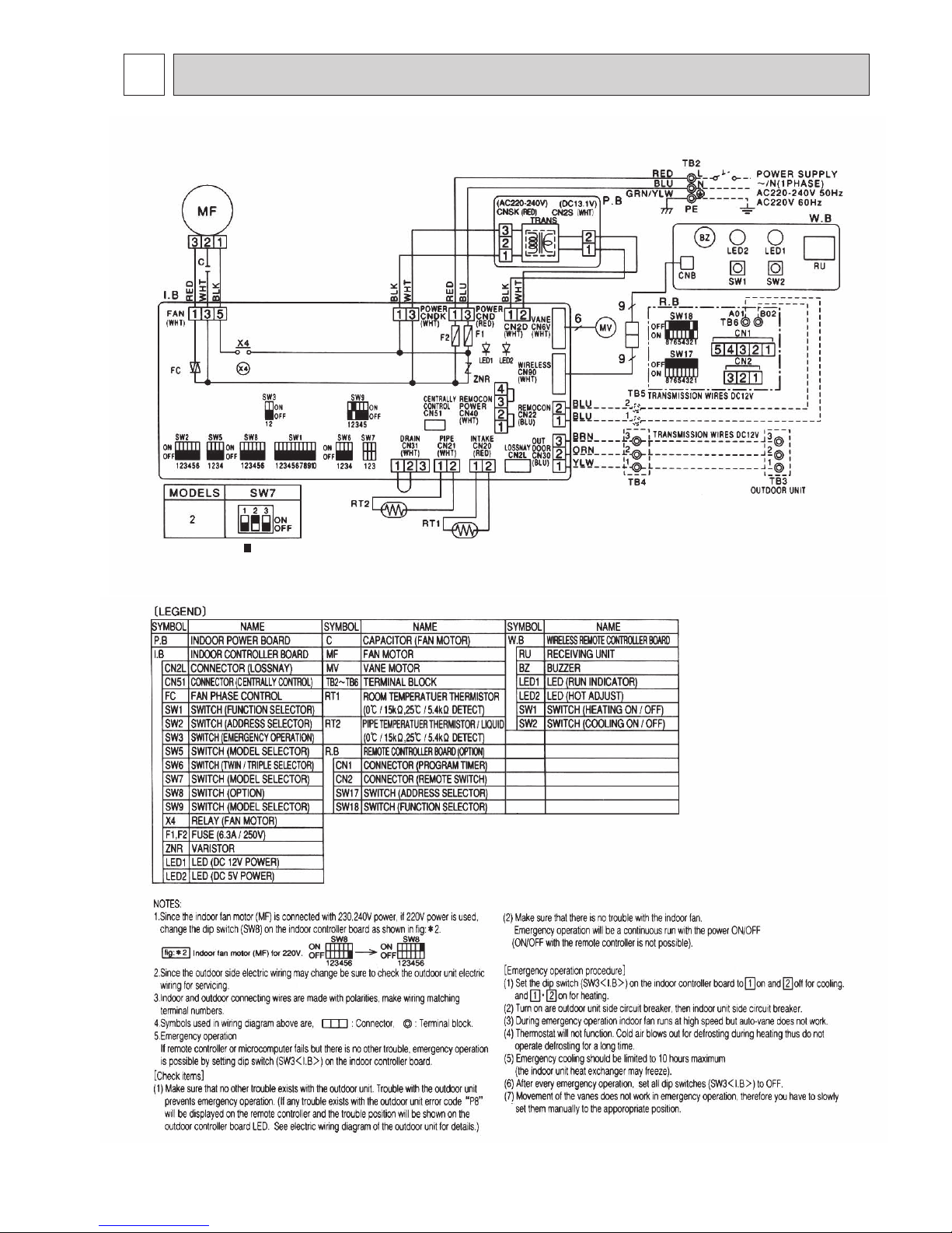
5
WIRING DIAGRAM
PKH-2GKLA
The black square ( ) indicates
a switch position.
OC231A
18 19
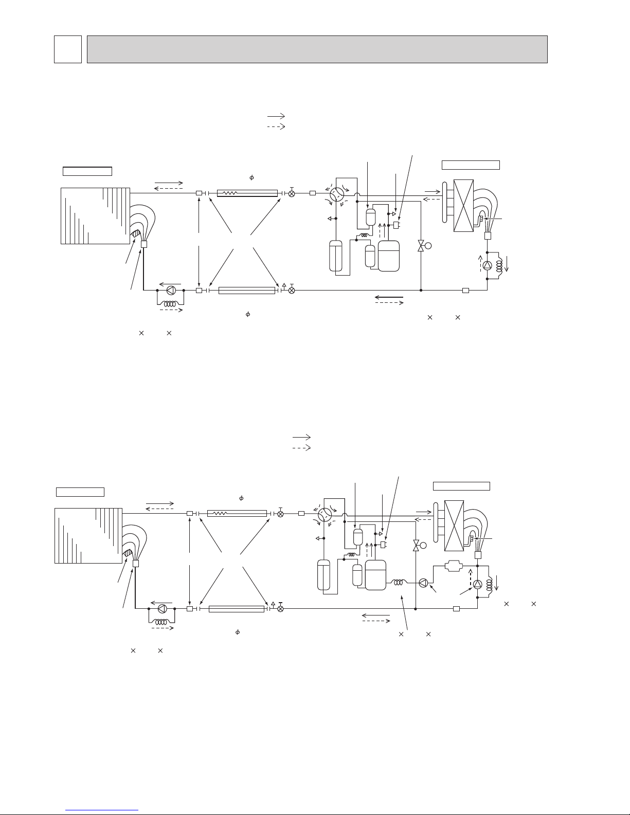
19
Indoor
heat
exchanger
Indoor unit
Refrigerant pipe
(option)
15.88mm( 5/8")
(with heat insulator)
Refrigerant pipe
(option)
9.52mm( 3/8")
(with heat insulator)
Flexible tube
Flared
connection
Ball valve
Strainer
Ball valve
(with Service port)
Oil separator
4-way valve
Service
port
Service
port
High pressure
control switch
Accumulator
Compressor
Strainer
Restrictor
valve
Outdoor heat exchanger
Outdoor coil
thermistor
(TH)
Pipe
temperature
thermistor
(RT2)
PKH-2 (O.D.3.2 I.D.1.8 N500)
PUH-2 (O.D.4.0 I.D.2.0 N430)
Distributor
with
strainer
Capillary
tube
Capillary
tube
Restrictor
valve
Strainer
Bypass
valve
Outdoor unit
Refrigerant flow in cooling
Refrigerant flow in heating
6
REFRIGERANT SYSTEM DIAGRAM
PKH-2GKLA / PUH-2VKA2 PUH-2AKA1·TH-A
Unit : mm
<4-Way valve solenoid coil>
Heating ON
Cooling OFF
PKH-2GKLA / PUH-2NKA1
Indoor
heat
exchanger
Indoor unit
Refrigerant pipe
(option)
15.88mm( 5/8")
(with heat insulator)
Refrigerant pipe
(option)
9.52mm( 3/8")
(with heat insulator)
Flexible tube
Flared
connection
Ball valve
Strainer
Ball valve
(with Service port)
Oil separator
4-way valve
Service
port
Service
port
High pressure
control switch
Accumulator
Compressor
Capillary
tube
Strainer
Restrictor
valve
Outdoor heat exchanger
Outdoor coil
thermistor
(TH)
Pipe
temperature
thermistor
(RT2)
PKH-2 (O.D.3.2 I.D.1.8 N500)
O.D.4.0 I.D.2.4 N430
Distributor
with
strainer
Capillary
tube
Capillary
tube
Restrictor
valve
Strainer
Bypass
valve
Muffler
Outdoor unit
O.D.3.2 I.D.1.2 N1250
Refrigerant flow in cooling
Refrigerant flow in heating
Unit : mm
<R.V. coil>
Heating ON
Cooling OFF
OC231A
19
7
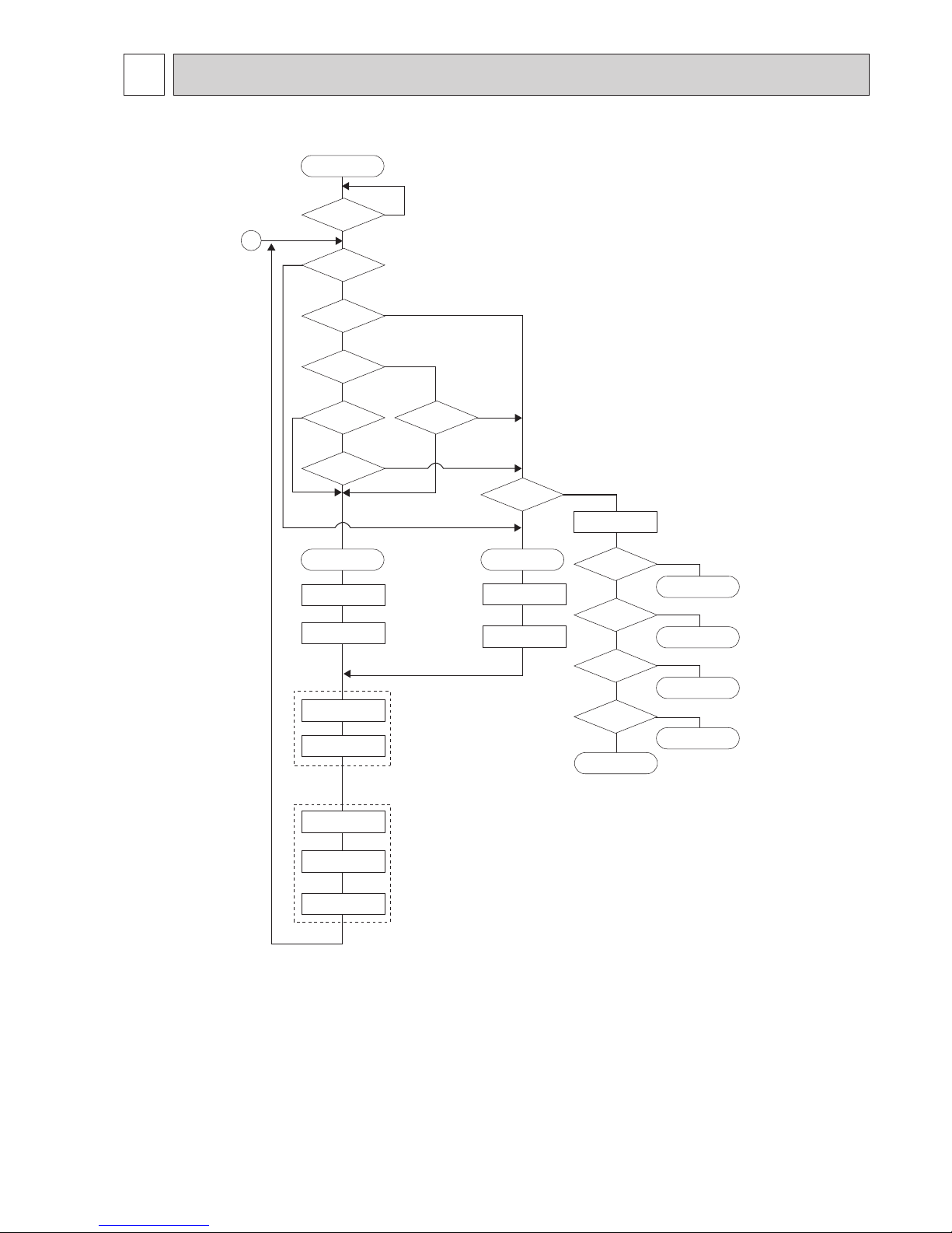
OPERATION FLOW-CHART
START
Power circuit
breaker
Check SW
ON twice
Operation SW
ON
“OFF” timer
“ON” timer
STOP
Set time
complete
Set time
complete
1
NO
NO
NO
NO
NO
NO
NO
NO
NO
NO
NO
NO
YES
YES
YES
YES
YES
YES
YES
YES
YES
YES
YES
YES
*1
*2
*3
*4
*5
*7
*6
PROTECTION DEVICE
SELF HOLD RELEASE
Remote controller
indicator lamp OFF
Trouble STOP
Remote controller
operation display
Operating mode
(COOL)
Operating mode
(DRY)
Operating mode
(HEAT)
Operating mode
(FAN)
Auto COOL/HEAT
operation
COOL operation
DRY operation
HEAT operation
FAN operation
Trouble
PROTECTION DEVICE
SELF HOLD
Remote controller
trouble display
Indoor side
Outdoor side
Fan STOP
Auxiliary heater OFF
Compressor OFF
Fan STOP
Four-way valve OFF
MAIN OPERATION
*1 In addition, the centralized control and remote control can be operated.
*2 The modes which indicate the sources of trouble are listed below.
● EO-Signal transmitting/receiving error
● P1-Room temperature thermistor malfunction
● P2-Pipe temperature thermistor malfunction
● P6-Coil frost/overheat protection
● P7-System error
● P8-Outdoor unit trouble
*3 The CHECK switch will show if an error has occurred in the past.
*4 Fan runs on low speed for 1 minute in order to remove overheat air.
*5 The 3-minute (6 minutes … heating mode) time-delay functions after compressor stops.
*6 FAN or AUTO mode is selected by the indoor dip switch setting.
*7 In FAN mode, fan speed and vane operation depend on the remote controller setting. (Compressor is OFF.)
OC231A
20 21
21
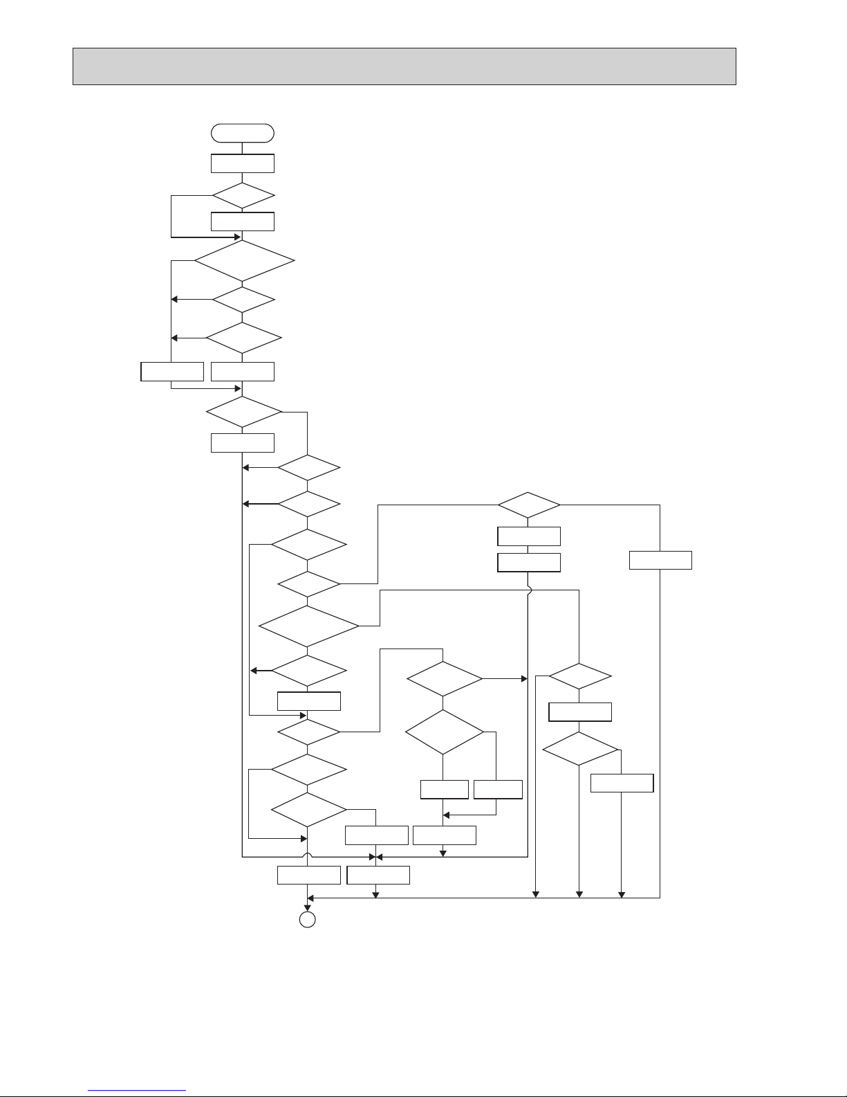
COOL operation
Four-way valve/OFF
Initial
COOLING
NO
NO
NO
NO
NO
YES
YES
YES
YES
YES
YES
NO
YES
YES
YES
YES
YES
YES
YES
YES
YES
YES
YES
NO
NO
NO
NO
YES
NO
NO
NO
NO
NO
NO
NO
NO
NO
*8
*9
Vane initial
setting
Vane
50 deg downward angle
60 deg downward angle
Fan speed
LOW
Downward discharge
1 hour
Vane setting notch
Vane horizontal
airflow
Compressor
thermostat
ON
Allowance
cancel
3-minute
time delay
6-minute
time delay
3-minute
compressoroperation
Coil frost
protection
Cooling area
10-minute
compressor operation
Allowance cancel
Coil frost
prevention
16-minute
compressoroperation
Indoor pipe
temperature is
1°C or lower
Compressor ON
1
*10
*11
Coil frost
prevention
Compressor OFF
Pipe
temperature is
10°C or higher
Defrosting protection
detection temperature
-1°C or lower
YES
NO
6-minute
time delay
3-minute
time delay
Coil frost
prevention release
Allowance
period
6 minute
time delay
Allowance set
1 min continue
Coil frost protection
FAN speed
LOW
FAN speed
LOW 5 min
elapse
Outdoor unit
trouble
COOLING OPERATION
*8 When operation stops or changes to cooling or dry mode, the auto vane turns to a horizontal angle. If operation changes
during auto vane SWING, the auto vane will continue to swing.
*9 When operating TEST RUN, the thermostat will be continuously ON.
*10 After 3 minute compressor operation, if the pipe temperature thermistor reads -15°C or below for 3 minutes, the compres
-
sor will stop for 6 minutes.
*11 Heating area : Pipe temperature is more than 5 degrees above the room temperature.
Cooling area : Pipe temperature is more than 5 degrees below the room temperature.
FAN area : Pipe temperature is within 5 degrees either way of the room temperature.
OC231A
21
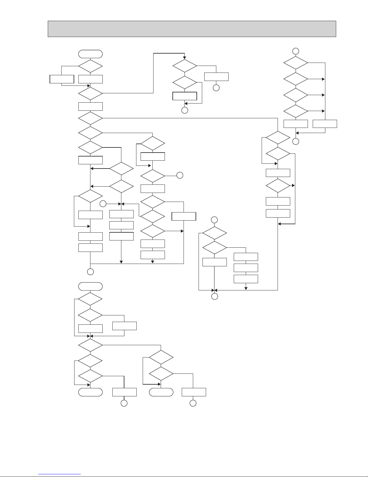
Heat operation
initial
HEATING
Vane setting notch
Vane initial setting
defrosting
Heating area
Defrost release
Defrost
30 min. elapse
Outdoor unit trouble
Four-way valve ON
Hot adjust
in process
Compressor ON
Compressor
thermostat ON
Allowance cancel
Indoor piping
-15°C or lower
Outdoor unit
trouble
FAN SPEED
Very low airflow
Compressor OFF
1
3 min.restart
prevention
6 min. restart
prevention
2
A
B
B
A
1
2
1
Hot adjust start
FAN SPEED very low
Compressor ON
10-minute
compressor
operation
Allowance cancel
Heating
area
FAN STOP
FAN area
20 min.elaspe
FAN area
Heating area
Outdoor unit
trouble
FAN area
Cooling area
Defrost operation
START
Four-way valve
OFF
Pipe
temperature
thermistor 70°C
or higher
Allowance
period
Overload protect
6-minute restart
prevention
Allowance set
Compressor OFF
Indoor piping
35°C or higher
HOT adjust
5 min. elapse
FAN SPEED
Low
FAN SPEED
Low 2 min.
elapse
FAN SPEED
setting notch
Hot adjust
release
PKH-GKLA
Type
3-minute
Auxiliary heater
OFF
Pipe
temperature
thermistor is 60°C
or higher
FAN speed
Low notch
Airflow 10% up
FAN setting notch
Auto COOL/HEAT
operation
Initial mode
T1 To
>
=
COOL mode
HEAT mode
COOL mode
T1 [ (To - 2)
After 15min.
T1 [ (To-2)
COOL operation
HEAT operation
1
1
T1 ] (To + 2)
After 15min.
T1 ] (To + 2)
HEAT operation
Cool mode
set
NO
NO
NO
NO
NO
*17
*16
NO
NO
YES
YES
YES
YES
YES
YES
YES
NO
NO
NO
NO
NO
NO
NO
NO
NO
NO
NO
NO
NO
NO
NO
NO
NO
YES
YES
YES
NO
NO
NO
NO
NO
NO
NO
NO
*11
*11
*11
* 9
*15
*11
w 10
YES
YES
YES
YES
YES
YES
YES
YES
YES
YES
YES
YES
YES
YES
YES
YES
YES
YES
YES
YES
YES
HEATING OPERATION
AUTOMATIC COOLING/HEATING OPERATION
*15 ( i ) Until Low airflow is set while in hot adjustment
(ii)While defrosting (FAN STOP)
(iii)When thermostat is OFF
In the case of( i ), (ii) and (iii) above, airflow is horizontal regardless the VANE setting.
*16 When AUTO operation is started, COOL or HEAT mode is selected automatically.
*17 T1 : Room temperature
To : Set temperature
OC231A
22 2323
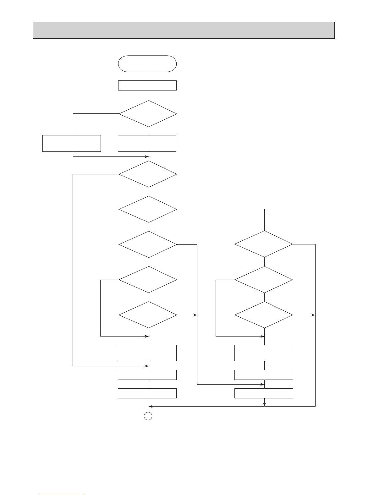
*8—9 Refer to page 28~29.
*12 When room temperature is 18°C or below, the compressor cannot operate.
When room temperature rises over 18°C, the compressor starts after a 3-minute time delay.
*13 Compressor ON time is decided by room temperature. Refer to page 28~29.
*14 In dry operation, compressor ON makes the fan speed LOW. Also, when the compressor OFF and the pipe tempera
ture is 26°C or less, the fan stops, or when the compressor OFF and the pipe temperature is below 6°C, the fan speed
changes to LOW mode.
It is not possible to set the fan speed with the remote controller.
DRY OPERATION
DRY
operation
Four-way valve / OFF
Initial dry
operation
Room temperature is
18°C or lower
During
compressor ON
Compressor &
thermostat ON
Vane initial setting
Vane
setting notch
10-minute compressor
OFF timer start
Compressor OFF
Fan STOP
3-minute
time delay
10-minute
compressor
OFF
Compressor ON
time set
Compressor ON
Fan speed LOW
1
Compressor &
thermostat
ON
3-minute
compressor
operation
Compressor ON
time completes
NO
YES
NO
NO
YES
*14
*14
*13
YES
YES
NO
YES
NO
NO
*9
YES
YES
*9
NO
NO
*12
YES
NO
YES
*8
OC231A
 Loading...