

Page 1
SPLIT-TYPE, HEAT PUMP AIR CONDITIONERS
TECHNICAL & SERVICE MANUAL
2001
No.OC271
Wall MountedSeries PKH
Indoor unit
[Model names] [Service Ref.]
PKH-2.5FKA PKH-2.5FKA1-E
PKH-3FKA PKH-3FKA1-E
PKH-4FKSA PKH-4FKSA1-E
CONTENTS
1. TECHNICAL CHANGES·······················2
2. TROUBLESHOOTING··························3
3. PARTS LIST··········································4
This service manual describes
change points and parts list.
Please refer to the OC190 as
to excluding this manual.
INDOOR UNIT
FILTER
CHECK MODE
TEST RUN
REMOTE CONTROLLER
Page 2

1 TECHNICAL CHANGES
PKH-2.5FKA-E ➔ PKH-2.5FKA1-E
PKH-3FKA-E ➔ PKH-3FKA
PKH-4FKSA-E ➔ PKH-4FKSA1-E
● NOSE has changed by changing its shape.
● UNDER PLATE has changed by changing its shape.
● DRAIN PAN has changed by changing its shape.
● BOX ASSEMBLY has changed by changing its shape.
1-E
2
Page 3
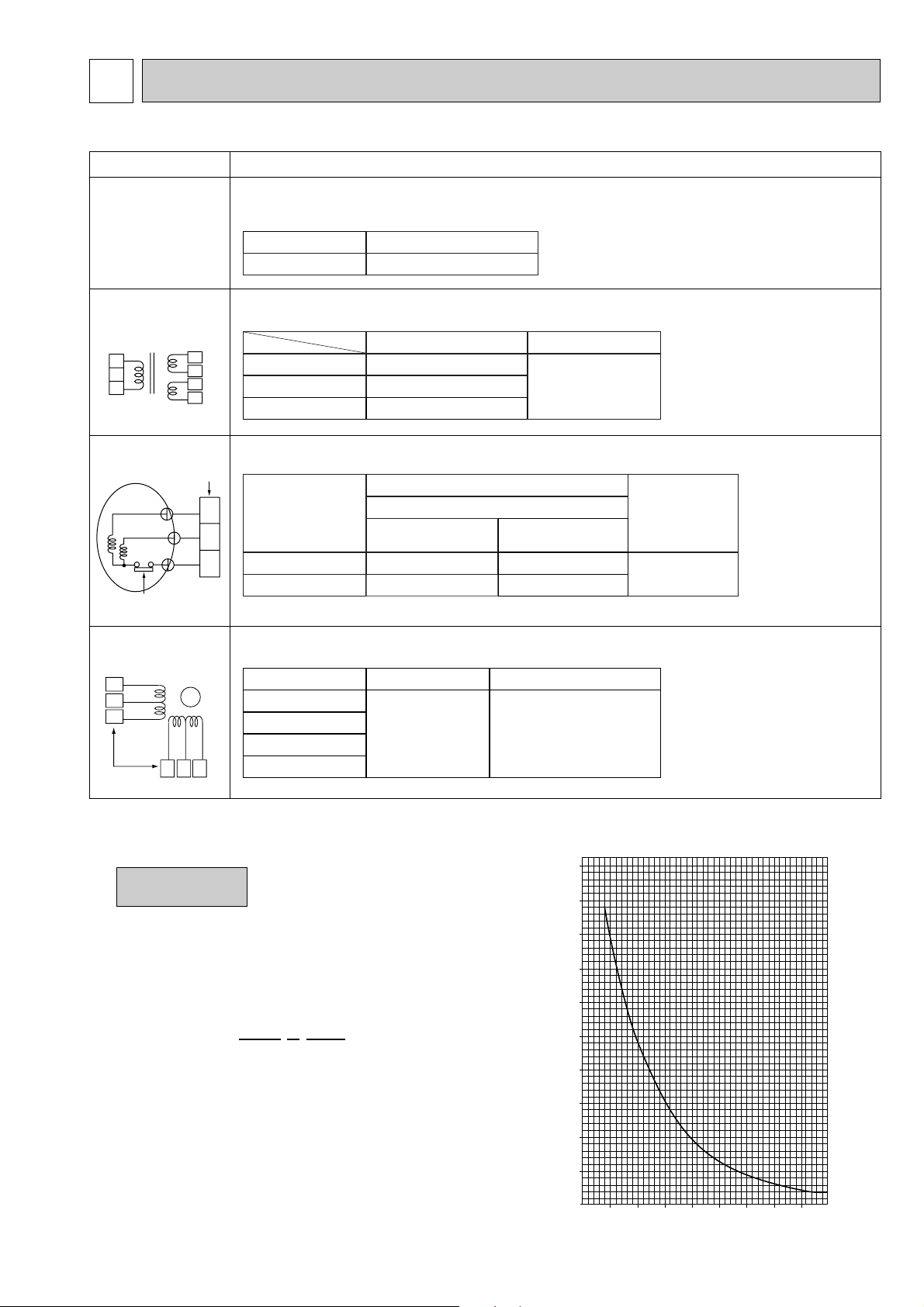
2 TROUBLESHOOTING
0
10
20
30
40
50
-20 -10 0 10 20 30 40 50
< Thermistor for lower temperature >
Temperature (:)
Resistance (K")
• How to check the parts PKH-2.5FKA1-E, PKH-3FKA1-E, PKH-4FKSA1-E
Parts name Check points
Room temperature
thermistor (RT1)
Pipe temperature
thermistor (RT2)
Disconnect the connector, then measure the resistance using a tester.
(Surrounding temperature 10°C~30°C)
Normal
4.3k'~9.6k'
Abnormal
Open or short
Trans
CNT T CN4T
WHT
1
2
3
YLW
BRN
RED
Fan motor
Relay connector
1
White
3
5
Black
Protector
Vane motor
Orange
4
Red
5
Pink
2
Yellow
Connector
3 6 1
1
2
3
4
Red
M
Brown
1
3
5
Blue
Disconnect the connector and measure the resistance using a tester.
Normal
CNT(1)-(3)
CN4T(1)-(2)
CN4T(3)-(4)
Measure the resistance between the terminals using a tester.
WHT. Approx. 135'
BRN. Approx. 0.5~2.0'
RED. Approx. 1.0~2.0'
Abnormal
Open or short
Normal
Motor terminal
or
Relay connector
Red-White
White-Black
Measure the resistance between the terminals using a tester.
(Surrounding temperature 20°C~30°C)
2.5, 3FKA-E
2.5, 3FKA1-E
99.5'i10%
103.5'i10%
Normal
PKH-
4FKSA-E
4FKSA1-E
62.6'i10%
74.0'i10%
Abnormal
Abnormal
Open or short
Brown-Yellow
Brown-Blue
Red-Orange
186~214'
Open or short
Red-Pink
<Thermistor Characteristic graph>
Thermistor for
lower temperature
Thermistor R0=15k' ±3%
Fixed number of B=3480k' ±2%
Rt=15exp { 3480( ) }
0: 15k'
10: 9.6k'
20: 6.3k'
25: 5.4k'
30: 4.3k'
40: 3.0k'
Room temperature thermistor(RT1)
Pipe temperature thermistor(RT2)
1
273+t
1
273
3
Page 4

3 PARTS LIST
Part No.
Specification
No.
Wiring
Diagram
Symbol
Recom-
mended
Q,ty
Price
Unit
Amount
Remarks
(
Drawing No.
)
Q,ty/set
PKH-2.5
PKH-4PKH-3
FKA-E
R01 12G 220
T7W 571 762
R01 12G 105
R01 16G 105
—
—
—
—
R01 13G 115
R01 17G 115
R01 13G 114
R01 17G 114
R01 005 103
R01 12G 103
Part Name
1
2
1
1
1
1
1
1
1
FKA1-E
FKA-E
FKA1-E
FKSA-E
FKSA1-E
1
2
1
1
1
1
1
1
1
1
2
3
4
5
6
7
8
9
1
2
1
1
1
1
1
1
1
1
2
1
1
1
1
1
1
1
1
2
1
1
1
1
1
1
1
1
2
1
1
1
1
1
1
1
MF
MF
(
BG02H065H01
)
(
BG02H178H01
)
(
BG02A534H16
)
(
BG02A534H17
)
D10A4P70MS
FAN MOTOR
FAN MOTOR
RUBBER MOUNT
RUBBER MOUNT
MOTOR BAND
MOTOR BAND
MOTOR LEG
MOTOR LEG
RIGHT LINEFLOW FAN
RIGHT LINEFLOW FAN
LEFT LINEFLOW FAN
LEFT LINEFLOW FAN
SLEEVE BEARING
SLEEVE BEARING
FILTER
CHECK MODE
TEST RUN
ELECTRICAL PARTS
PKH-2.5FKA-E PKH-3FKA-E PKH-4FKSA-E
PKH-2.5FKA1-E PKH-3FKA1-E PKH-4FKSA1-E
10
22
14
16
19
8
37·38
34
39
5
7
11
9
12
13
6
1
3
31
25
26
18
17
16
4
2
35
28
27
322033
29
21
15 36
4
30 23 24
Page 5

Part No.
No.
Price
Remarks
(
Drawing No.
)
Q,ty/set
PKH-2.5
PKH-3 PKH-4
FKA-E FKA-E
FKSA-E
R01 Z61 102
R01 KV5 102
—
—
R01 12G 529
T7W E13 529
R01 16G 529
T7W E14 529
R01 12G 223
—
—
—
R01 12G 002
R01 16G 002
R01 12G 621
R01 12G 063
R01 KV5 527
T7W 585 480
T7W 587 480
T7W 589 480
T7W 71J 310
T7W 520 239
—
—
T7W 509 716
T7W 517 716
—
R01 588 255
R01 576 255
T7W 50J 799
R01 06A 202
R01 22A 202
T7W 53J 200
T7W 512 716
T7W 556 305
T7W 53J 675
T7W 71J 675
R01 08K 049
Part Name
Specification
250V 6.3A
3P(L/N/;)
3P(1/2/3)
2.0µF 440V
3.0µF 440V
2P(1/2)
12m
1
1
1
1
1
1
20
4
3
2
1
1
1
1
1
2
1
1
1
1
1
1
1
1
1
1
1
1
2
1
10
11
12
13
14
15
16
17
18
19
20
21
22
23
24
25
26
27
28
29
30
31
32
33
34
35
36
37
38
39
1
1
1
1
1
1
20
4
3
2
1
1
1
1
1
2
1
1
1
1
1
1
1
1
1
1
1
1
2
1
1
1
1
1
1
1
26
4
4
2
1
1
1
1
1
2
1
1
1
1
1
1
1
1
1
1
1
1
2
1
FKA1-E FKA1-E
FKSA1-E
1
1
1
1
1
1
20
4
3
2
1
1
1
1
1
2
1
1
1
1
1
1
1
1
1
1
1
1
2
1
1
1
1
1
1
1
20
4
3
2
1
1
1
1
1
2
1
1
1
1
1
1
1
1
1
1
1
1
2
1
1
1
1
1
1
1
26
4
4
2
1
1
1
1
1
2
1
1
1
1
1
1
1
1
1
1
1
1
2
1
MV
I.B
F1.2<I.B>
TB2
TB4
C
C
T
RT1
RT2
R.B
TB5
(
BG02L462H02
)
(
BG00R259G07
)
(
BG25J821H02
)
(
BG25J821H02
)
(
BG00R259G07
)
(
BG25B573H06
)
(
BG02A648G02
)
(
BG02J608H07
)
Wiring
Diagram
Symbol
Recommended
Q,ty
Unit
Amount
BEARING MOUNT
BEARING MOUNT
BEARING BAND
CENTER SUPPORT
DRAIN PAN
DRAIN PAN
DRAIN PAN
DRAIN PAN
VANE MOTOR
GUIDE VANE
GUIDE VANE(WITH HANDLE)
ARM
AUTO VANE
AUTO VANE
CENTER COVER
JOINT SHAFT
DRAIN HOSE
HEAT EXCHANGER
HEAT EXCHANGER
HEAT EXCHANGER
INDOOR CONTROLLER BOARD
FUSE
CONTROLLER CASE
CONTROLLER COVER
TERMINAL BLOCK
TERMINAL BLOCK
TERMINAL COVER
FAN MOTOR CAPACITOR
FAN MOTOR CAPACITOR
TRANSFORMER
ROOM TEMPERATURE THERMISTOR
INDOOR COIL THERMISTOR
REMOTE CONTROLLER BOARD
TERMINAL BLOCK
REMOTE CONTROLLER CABLE
FAN GUARD
FAN GUARD
REMOTE CONTROLLER COVER
5
Page 6

Part No.
No.
Price
Remarks
(
Drawing No.
)
R01 12G 661
R01 12G 662
R01 12G 691
R01 16G 692
R01 A17 500
R01 12G 811
R01 E00 811
R01 16G 811
R01 E01 811
R01 E01 812
R01 E00 812
T7W E01 641
T7W E00 641
R01 12G 523
R01 12G 808
R01 16G 808
—
—
—
—
Part Name
Specification
Q,ty/set
PKH-2.5 PKH-3 PKH-4
FKA-E FKA-E
FKSA-E
1
1
2
4
1
1
1
1
1
1
FKA1-E
1
1
2
4
1
1
1
1
1
1
1
2
3
4
5
6
7
8
9
10
11
1
1
2
4
1
1
1
1
1
1
FKA1-E
1
1
2
4
1
1
1
1
1
1
1
1
2
1
5
1
1
1
1
1
1
FKSA1-E
1
1
2
1
5
1
1
1
1
1
1
(BG00A593GM3)
(RG00A734G29)
(BG00A593GM4)
(RG00A734G30)
Wiring
Diagram
Symbol
Recommended
Q,ty
Unit
Amount
RIGHT SIDE PANEL
LEFT SIDE PANEL
INTAKE GRILLE
INTAKE GRILLE
AIR FILTER
NOSE
NOSE
NOSE
NOSE
UNDER PLATE
UNDER PLATE
TOP PLATE
TOP PLATE
DRAIN SOKET
BACK PLATE
BACK PLATE
BOX ASSEMBLY
BOX ASSEMBLY
BOX ASSEMBLY
BOX ASSEMBLY
STRUCTURAL PARTS
PKH-2.5FKA-E PKH-3FKA-E PKH-4FKSA-E
PKH-2.5FKA1-E PKH-3FKA1-E PKH-4FKSA1-E
11
108
2
7
6
3
5
Part number that is circled is not shown in the figure.
6
1
Page 7

Page 8

HEAD OFFICE : MITSUBISHI DENKI BLDG., 2-2-3, MARUNOUCHI, CHIYODA-KU, TOKYO100-8310, JAPAN
cCopyright 2001 MITSUBISHI ELECTRIC ENGINEERING CO.,LTD
Distributed in Sep. 2001. No.OC271 660
Made in Japan
New publication, effective Sep. 2001.
Specifications subject to change without notice
 Loading...