

Page 1
SPLIT-TYPE,HEAT PUMP AIR CONDITIONERS
ON/OFF
TECHNICAL & SERVICE MANUAL
2000
No.OC229
Series PKH
Wall Mounted
Indoor unit
[ Model names ] [ Service Ref. ]
PKH-1.6GKL PKH-1.6GKL
PKH-1.6GKLH PKH-1.6GKLH
PKH-2GKL PKH-2GKL
PKH-2GKLH PKH-2GKLH
CONTENTS
1. PART NAMES AND FUNCTIONS ·······················2
2. SPECIFICATIONS················································4
3. DATA·····································································6
4. OUTLINES AND DIMENSIONS·························14
Indoor unit
5. WIRING DIAGRAM ············································15
6.
7. OPERATION FLOW-CHART ·····························17
8. MICROPROCESSOR CONTROL······················21
9. TROUBLESHOOTING ·······································41
10. SYSTEM CONTROL ··········································51
11. DISASSEMBLY PROCEDURE···························56
12. PARTS LIST ·······················································60
13. OPTIONAL PARTS·············································63
This manual does not cover
the following outdoor units.
When servicing them, please
refer to the service manual
No.OC128 REVISED EDITION-A and this manual in a
set.
[Service Ref.]
PUH-1.6VKA
PUH-2VKA2
REFRIGERANT SYSTEM DIAGRAM
2
······················16
Remote controller
Page 2
1 PART NAMES AND FUNCTIONS
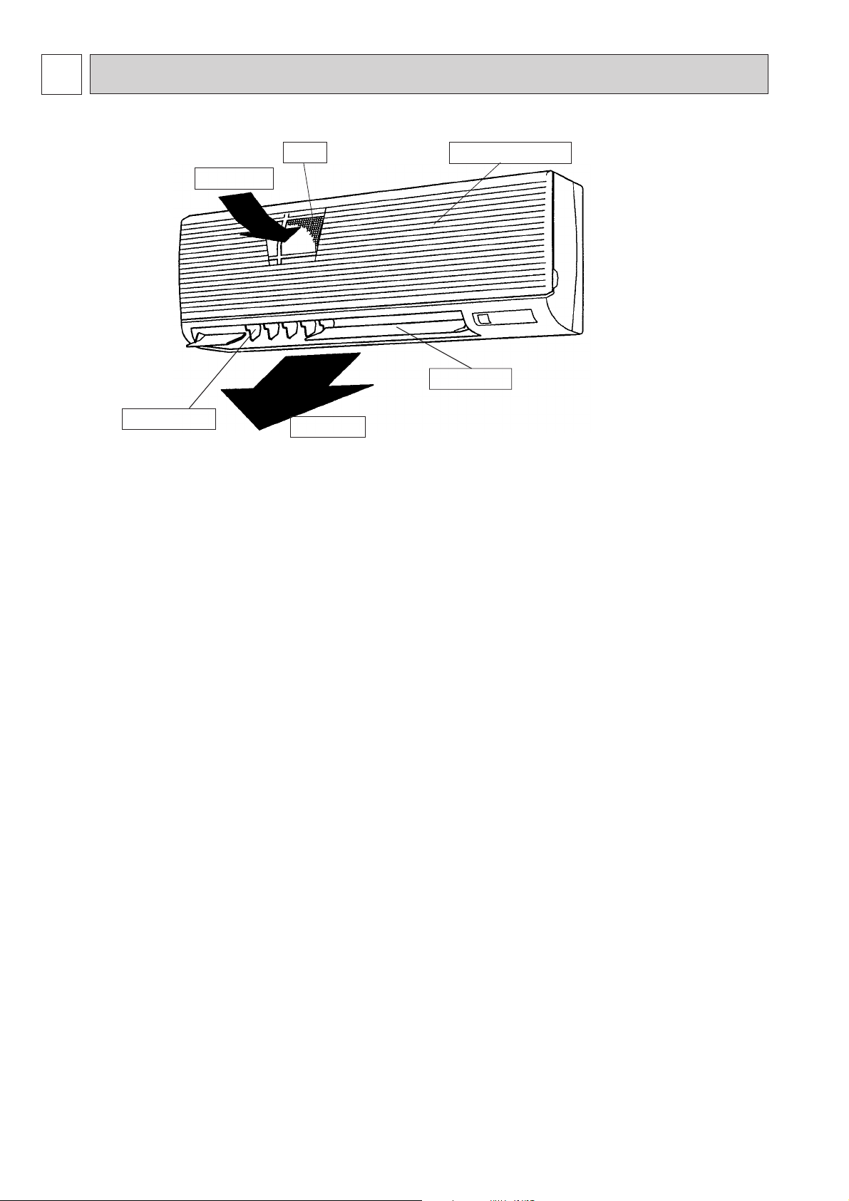
● Indoor Unit
Air intake
Guide vane
Filter
Air outlet
Air intake grille
Auto vane
2
Page 3
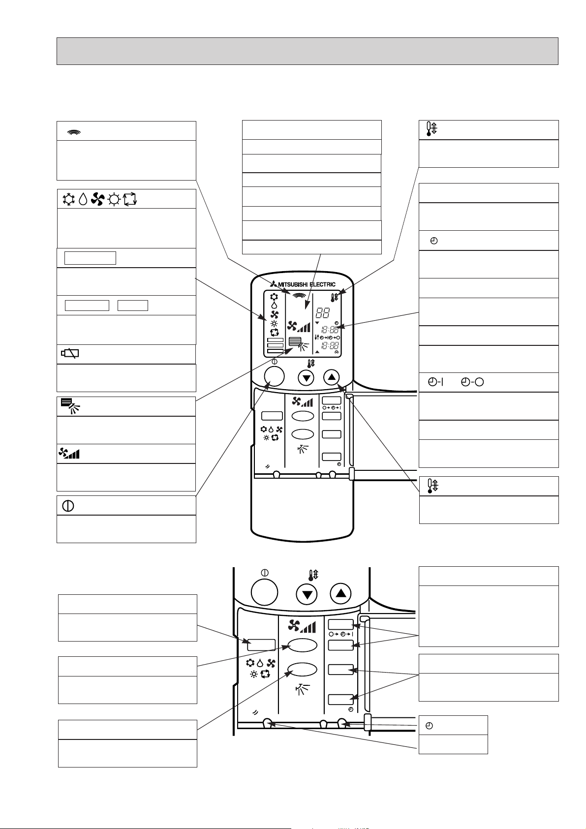
●Wireless remote controller
● When cover is open.
display
Lights up while transmission to the indoor unit
is mode using switches.
display
OPERATION MODE display
Operation mode display indicates which operation mode is in effect.
• FUNCTION
Lights up when function are set..
display
• TEST RUN • CHECK display
CHECK&TEST RUN display indicates that the
unit is being checked or test-run.
display
Displays when batteries are dead.
display
The vertical direction of airflow is indicated.
display
FAN SPEED display indicates which fan
speed has been selected.
ADDRESS display
Displays the refrigerant address.
UNIT NO. display
Displays the number of unit..
FUNCTION NO. display
Displays the mode.
SELECTION NO. display
Displays the selection number..
ADDRESS
UNIT No.
FUNCTION No.
SELECTION No.
FUNCTION
TEST RUN
CHECK
ON/OFF
MODE FAN
RESET
VANE
AM
PM
AM
PM
TEMP.
˚C
START
STOP
HR.
MIN.
display
SET TEMP. display indicates desired temperature set.
CLOCK display
DIsplays the current time.
“ ”display
Flashes when the current time is displayed.
TIMER display
Displays when in timer operation or when setting timer.
➡
“ ” “ ” display
➡
Displays the order of timer operation.
“ ” “ ” display
Displays whether timer is on or off.
▼
“ ” “ ” display
Displays when the current time and the timer
time can be changed.
▼
TEMP. button
display
The unit is turned ON and OFF alternately
each time the button is pressed.
● When cover is open.
MODE SELECT button
Used to switch the operation mode between
cooling , drying , blowing , heating and auto
mode.
FAN SPEED SELECT button
Used to change the fan speed.
VANE CONTROL button
Used to change the airflow direction.
ON/OFF
MODE FAN
RESET
VANE
TEMP.
START
STOP
HR.
MIN.
SET TEMPERATURE button sets any desired
room temperature.
TIMER CONTROL buttons
STOP (OFF timer): when this switch is set,
the air conditioner will be automatically
stopped at the preset time.
START(ON timer): when this switch is set, the
air conditioner will be automatically started at
the preset time.
HR. and MIN.buttons
Buttons used to set the “hour and minute” of
the current time and timer settings.
button
RESET button
3
Page 4
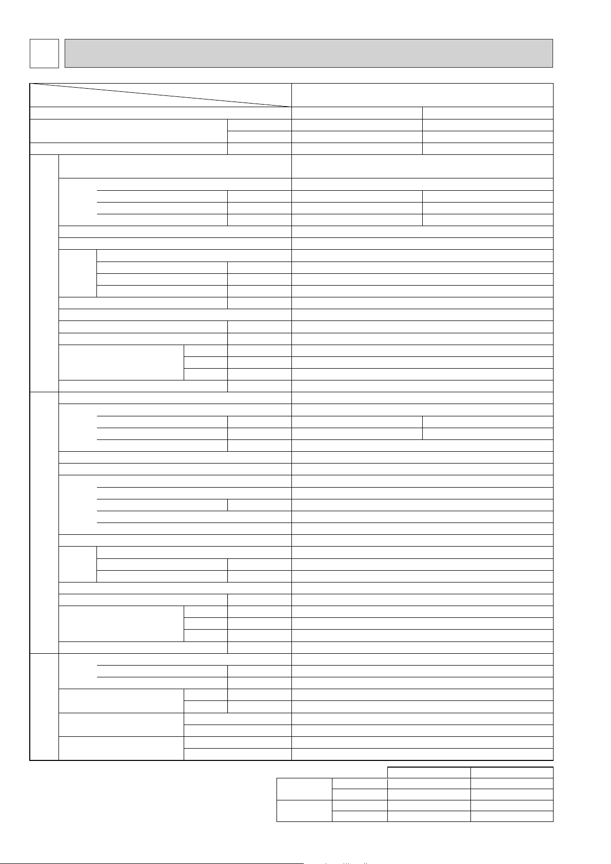
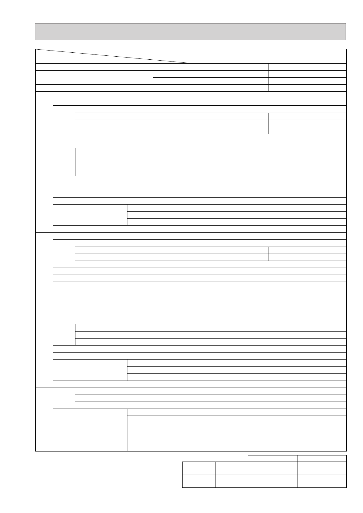
2
Item
Function
Capacity
Total input
Service Ref.
Power supply(phase, cycle, voltage)
Input
Running current
Starting current
External finish
Heat exchanger
Fan Fan(drive) ✕ No.
Fan motor output
Airflow(Low-High)
External static pressure
Booster heater
Operation control & Thermostat
Noise level(Low-High)
Unit drain pipe O.D.
Dimensions
Weight
Service Ref.
Power supply (phase, cycle, voltage)
Input
Running current
Starting current
External finish
Refrigerant control
Compressor
Model
Motor output
Starter type
Protection devices
Heat exchanger
Fan Fan(drive)✕No.
Fan motor output
Airflow
Defrost method
Noise level
Dimensions
Weight
Refrigerant
Charge
Oil<Model>
Pipe size O.D.
Connection method
Between the indoor & outdoor unit
Service Ref.
W
D
H
W
D
H
Liquid A(in.)
Gas A(in.)
Indoor side
Outdoor side
Height difference
Piping length
INDOOR UNITOUTDOOR UNIT
REFRIGERANT PIPING
W
Btu/h
kW
kW
A
A
kW
m
3
/X<CFM>
Pa(mmAq)
kW
>
A(in.)
A(in.)
A(in.)
A(in.)
kg(lbs)
kW
A
A
kW
kW
m
3
/X<CFM>
>
A(in.)
A(in.)
A(in.)
kg(lbs)
kg(lbs)
L
PKH-1.6GKL
PKH-1.6GKLH
Cooling
4,500
15,350
1.51
0.07
0.33
0.40
1.44
6.74
Heating
4,650 (5,450)
15,900 (18,600)
1.48 (2.28)
0.07 (0.87)
0.33 (3.66)
0.40 (3.73)
1.41
6.60
PKH-1.6GKL
PKH-1.6GKLH
Single, 50Hz, 220-240V
Munsell 0.70Y 8.59/0.97
Plate fin coil
Line flow(direct) ✕ 1
0.030
9-12 (318-424)
0(direct blow)
(0.8)
Remote controller & built-in
36-43
20(13/16)
990 (39)
235 (9-1/4)
340 (13-3/8)
16(35) (17(37))
PUH-1.6VKA
2
Single, 50Hz, 220-240V
33
Munsell 5Y 7/1
Capillary tube
Hermetic
RH247VFC
1.2
Line start
Internal thermostat, HP switch
Plate fin coil
Propeller (direct) ✕ 1
0.065
45(1,590)
Reverse cycle
49
870(34-1/4)
295+24(11-5/8 add 1)
650(25-5/8)
53(117)
R-22
2.2(4.9)
0.57<MS-56>
9.52(3/8)
15.88(5/8)
Flared
Flared
Max. 40m
Max. 40m
2.
Guaranteed operating range
Cooling
Heating
Upper limit
Lower limit
Upper limit
Lower limit
Indoor
D.B. 35:, W.B. 22.5:
D.B. 21:, W.B. 15.5:
D.B. 27:
D.B. 20:
Outdoor
D.B. 46:
D.B. -5:
D.B. 21:, W.B. 15.5:
D.B. -8.5:, W.B. -9.5:
SPECIFICATIONS
Note1. Rating Conditions (JIS B 8616)
Cooling : Indoor : D.B. 27°C (80°F), W.B. 19°C (66°F)
Heating : Indoor : D.B. 20°C (68°F)
Outdoor : D.B. 35°C (95°F), W.B. 24°C (75°F)
Outdoor : D.B. 7°C (45°F), W.B. 6°C (43°F)
4
Page 5
Item
Function
Capacity
Total input
Service Ref.
Power supply(phase, cycle, voltage)
Input
Running current
Starting current
External finish
Heat exchanger
Fan Fan(drive) ✕ No.
Fan motor output
Airflow(Low-High)
External static pressure
INDOOR UNITOUTDOOR UNIT
Booster heater
Operation control & Thermostat
Noise level(Low-High)
Unit drain pipe O.D.
Dimensions
Weight
Service Ref.
Power supply (phase, cycle, voltage)
Input
Running current
Starting current
External finish
Refrigerant control
Compressor
Model
Motor output
Starter type
Protection devices
Heat exchanger
Fan Fan(drive)✕No.
Fan motor output
Airflow
Defrost method
Noise level
Dimensions
Weight
Refrigerant
Charge
Oil<Model>
Pipe size O.D.
Connection method
Between the indoor & outdoor unit
REFRIGERANT PIPING
Note1. Rating Conditions (JIS B 8616)
Cooling : Indoor : D.B. 27°C (80°F), W.B. 19°C (66°F)
Heating : Indoor : D.B. 20°C (68°F)
Outdoor : D.B. 35°C (95°F), W.B. 24°C (75°F)
Outdoor : D.B. 7°C (45°F), W.B. 6°C (43°F)
Liquid A(in.)
Gas A(in.)
Indoor side
Outdoor side
Height difference
Piping length
W
W
Service Ref.
W
Btu/h
kW
Cooling
5,500
18,800
2.27
PKH-2GKL
PKH-2GKLH
Heating
6,250 (7,050)
21,300 (24,100)
2.29 (3.09)
PKH-2GKL
PKH-2GKLH
Single, 50Hz, 220-240V
kW
A
A
0.07
0.33
0.40
0.07 (0.87)
0.33 (3.66)
0.40 (3.73)
Munsell 0.70Y 8.59/0.97
Plate fin coil
Line flow(direct) ✕ 1
kW
3
/X<CFM>
m
Pa(mmAq)
kW
0.030
9-12 (318-424)
0(direct blow)
(0.8)
Remote controller & built-in
>
A(in.)
A(in.)
D
H
A(in.)
A(in.)
kg(lbs)
36-43
20(13/16)
990 (39)
235 (9-1/4)
340 (13-3/8)
16(35) (17(37))
PUH-2VKA
2
Single, 50Hz, 220-240V
kW
A
A
2.20
9.86
45
2.22
9.95
Munsell 5Y 7/1
Capillary tube
Hermetic
NH38VMD
kW
1.7
Line start
Internal thermostat, HP switch
Plate fin coil
Propeller (direct) ✕ 1
kW
3
/X<CFM>
m
0.065
45(1,590)
Reverse cycle
>
A(in.)
D
H
A(in.)
A(in.)
295+24(11-5/8 add 1)
kg(lbs)
49
870(34-1/4)
650(25-5/8)
64(141)
R-22
kg(lbs)
L
2.2(4.9)
1.2<MS-32>
9.52(3/8)
15.88(5/8)
Flared
Flared
Max. 40m
Max. 40m
Guaranteed operating range
2.
Cooling
Heating
Upper limit
Lower limit
Upper limit
Lower limit
Indoor
D.B. 35:, W.B. 22.5:
D.B. 21:, W.B. 15.5:
D.B. 27:
D.B. 20:
Outdoor
D.B. 46:
D.B. -5:
D.B. 21:, W.B. 15.5:
D.B. -8.5:, W.B. -9.5:
5
Page 6
3 DATA
Outdoor intake air D.B.(°C)
20 25 30
Indoor
Intake air
D.B.(°C)
Indoor
Intake air
W.B.(°C)
20
20
20
22
22
22
24
24
24
24
26
26
26
26
27
27
27
27
28
28
28
28
30
30
30
30
32
32
32
32
16
18
20
16
18
20
16
18
20
22
16
18
20
22
16
18
20
22
16
18
20
22
16
18
20
22
16
18
20
22
CA
4540
4834
5131
4540
4834
5131
4540
4834
5131
5431
4540
4834
5131
5431
4540
4834
5131
5431
4540
4834
5131
5431
4540
4834
5131
5431
4540
4834
5131
5431
SHC(W)
2996
2610
2155
3359
2997
2565
3723
3384
2976
2498
4086
3770
3386
2933
4267
3964
3592
3150
4449
4157
3797
3367
4540
4544
4207
3802
4540
4834
4618
4236
SHF
0.66
0.54
0.42
0.74
0.62
0.50
0.82
0.70
0.58
0.46
0.90
0.78
0.66
0.54
0.94
0.82
0.70
0.58
0.98
0.86
0.74
0.62
1.00
0.94
0.82
0.70
1.00
1.00
0.90
0.78
P.C.
1.21
1.23
1.26
1.21
1.23
1.26
1.21
1.23
1.26
1.28
1.21
1.23
1.26
1.28
1.21
1.23
1.26
1.28
1.21
1.23
1.26
1.28
1.21
1.23
1.26
1.28
1.21
1.23
1.26
1.28
CA
4415
4706
5010
4415
4706
5010
4415
4706
5010
5327
4415
4706
5010
5327
4415
4706
5010
5327
4415
4706
5010
5327
4415
4706
5010
5327
4415
4706
5010
5327
SHC(W)
2914
2541
2104
3267
2918
2505
3621
3294
2906
2450
3974
3671
3307
2877
4151
3859
3507
3090
4327
4047
3708
3303
4415
4424
4108
3729
4415
4706
4509
4155
SHF
0.66
0.54
0.42
0.74
0.62
0.50
0.82
0.70
0.58
0.46
0.90
0.78
0.66
0.54
0.94
0.82
0.70
0.58
0.98
0.86
0.74
0.62
1.00
0.94
0.82
0.70
1.00
1.00
0.90
0.78
P.C.
1.26
1.29
1.31
1.26
1.29
1.31
1.26
1.29
1.31
1.34
1.26
1.29
1.31
1.34
1.26
1.29
1.31
1.34
1.26
1.29
1.31
1.34
1.26
1.29
1.31
1.34
1.26
1.29
1.31
1.34
CA
4253
4535
4831
4253
4535
4831
4253
4535
4831
5142
4253
4535
4831
5142
4253
4535
4831
5142
4253
4535
4831
5142
4253
4535
4831
5142
4253
4535
4831
5142
SHC(W)
2807
2449
2029
3147
2812
2416
3488
3174
2802
2365
3828
3537
3189
2777
3998
3719
3382
2983
4168
3900
3575
3188
4253
4263
3962
3600
4253
4535
4348
4011
SHF
0.66
0.54
0.42
0.74
0.62
0.50
0.82
0.70
0.58
0.46
0.90
0.78
0.66
0.54
0.94
0.82
0.70
0.58
0.98
0.86
0.74
0.62
1.00
0.94
0.82
0.70
1.00
1.00
0.90
0.78
P.C.
1.36
1.39
1.42
1.36
1.39
1.42
1.36
1.39
1.42
1.45
1.36
1.39
1.42
1.45
1.36
1.39
1.42
1.45
1.36
1.39
1.42
1.45
1.36
1.39
1.42
1.45
1.36
1.39
1.42
1.45
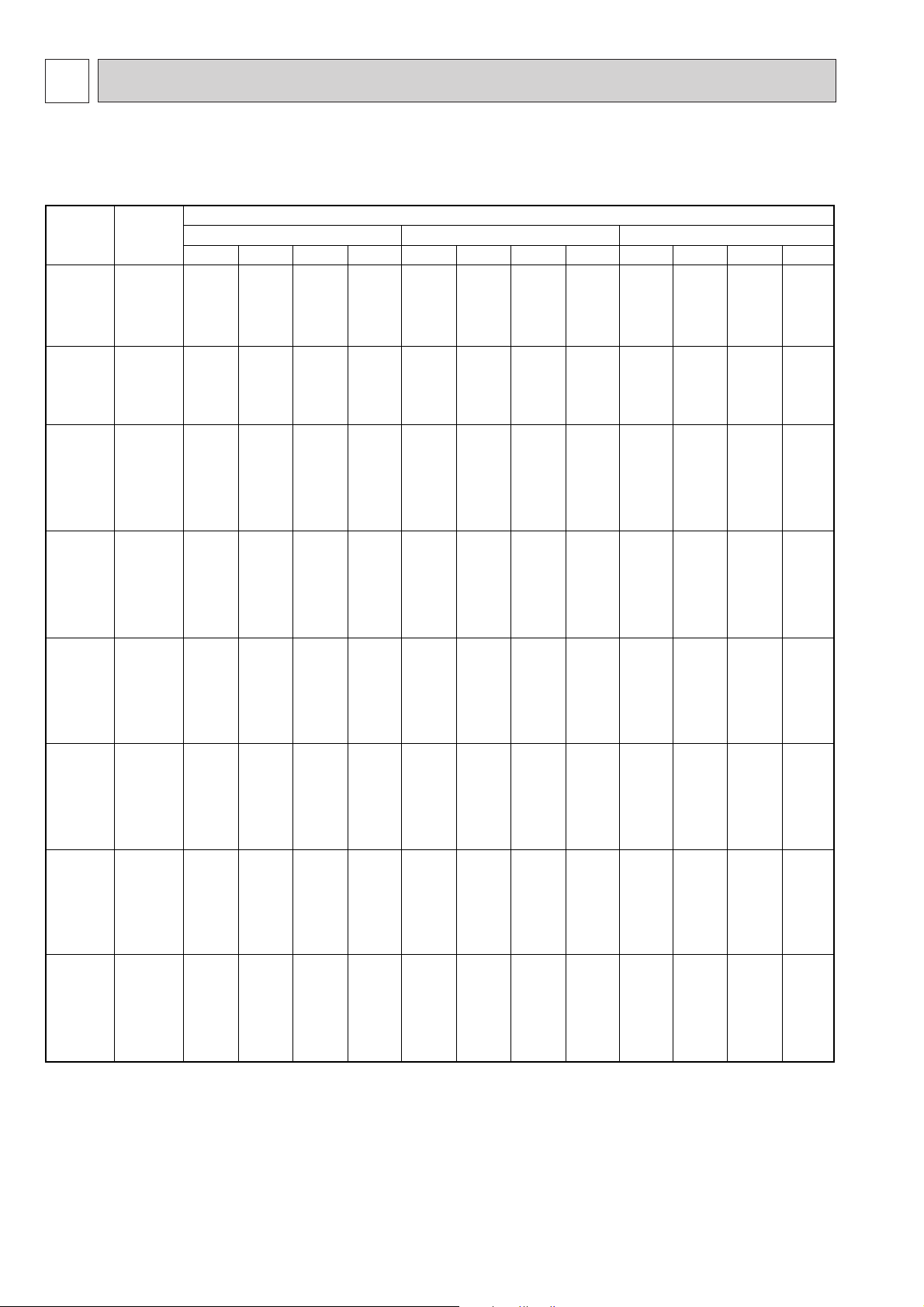
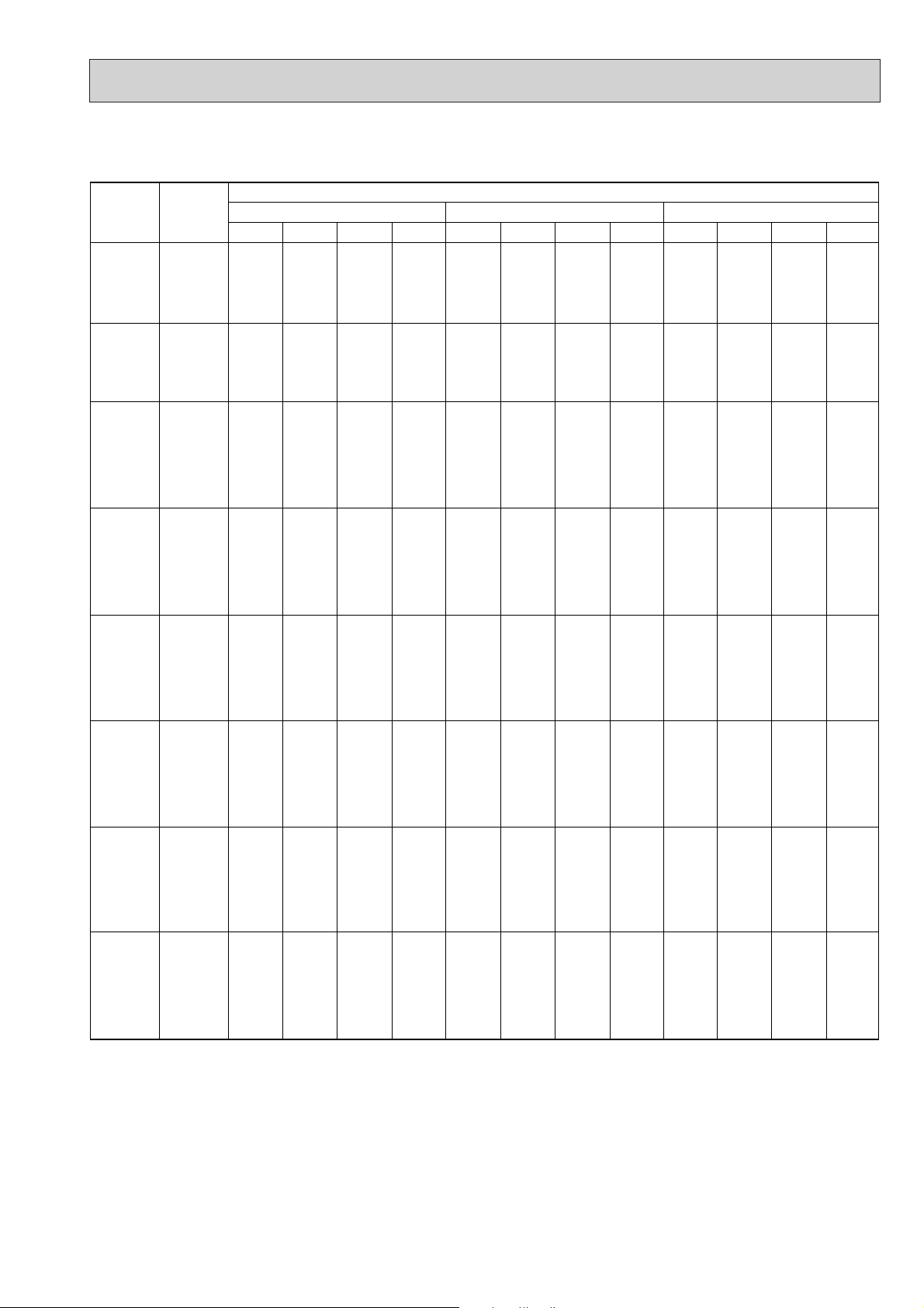
1. PERFORMANCE DATA
1) COOLING CAPACITY<1>
PKH-1.6GKL
PKH-1.6GKLH
CA : Capacity (W) SHC(W) : Sensible heat capacity
P.C. : Power consumption (kW) SHF : Sensible heat factor
6
Page 7
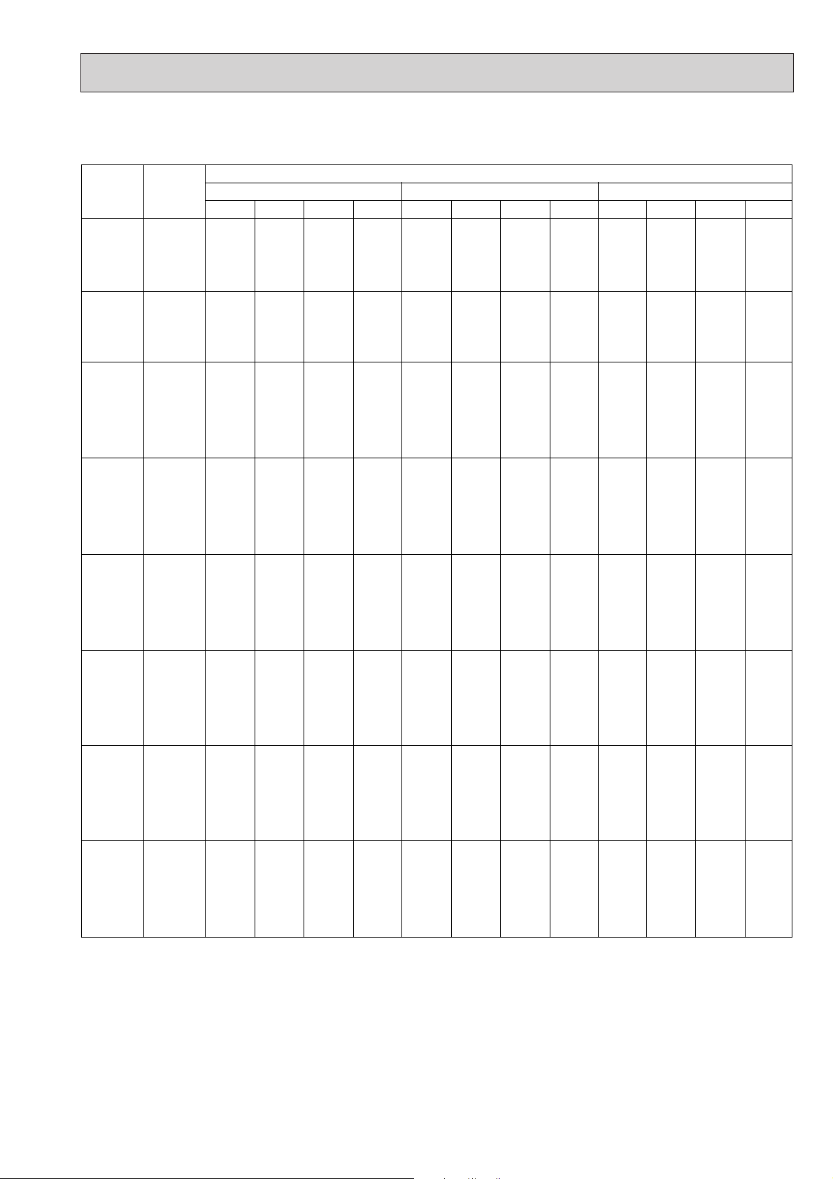
COOLING CAPACITY<2>
Outdoor intake air D.B.(°C)
35 40 45
Indoor
Intake air
D.B.(°C)
Indoor
Intake air
W.B.(°C)
20
20
20
22
22
22
24
24
24
24
26
26
26
26
27
27
27
27
28
28
28
28
30
30
30
30
32
32
32
32
16
18
20
16
18
20
16
18
20
22
16
18
20
22
16
18
20
22
16
18
20
22
16
18
20
22
16
18
20
22
CA
4081
4355
4645
4081
4355
4645
4081
4355
4645
4950
4081
4355
4645
4950
4081
4355
4645
4950
4081
4355
4645
4950
4081
4355
4645
4950
4081
4355
4645
4950
SHC(W)
2693
2352
1951
3020
2700
2322
3346
3049
2694
2277
3673
3397
3066
2673
3836
3571
3251
2871
3999
3745
3437
3069
4081
4094
3809
3465
4081
4355
4180
3861
SHF
0.66
0.54
0.42
0.74
0.62
0.50
0.82
0.70
0.58
0.46
0.90
0.78
0.66
0.54
0.94
0.82
0.70
0.58
0.98
0.86
0.74
0.62
1.00
0.94
0.82
0.70
1.00
1.00
0.90
0.78
P.C.
1.46
1.49
1.53
1.46
1.49
1.53
1.46
1.49
1.53
1.56
1.46
1.49
1.53
1.56
1.46
1.49
1.53
1.56
1.46
1.49
1.53
1.56
1.46
1.49
1.53
1.56
1.46
1.49
1.53
1.56
CA
3899
4167
4451
3899
4167
4451
3899
4167
4451
4750
3899
4167
4451
4750
3899
4167
4451
4750
3899
4167
4451
4750
3899
4167
4451
4750
3899
4167
4451
4750
SHC(W)
2573
2250
1869
2885
2583
2225
3197
2917
2581
2185
3509
3250
2937
2565
3665
3417
3116
2755
3821
3583
3294
2945
3899
3917
3650
3325
3899
4167
4006
3705
SHF
0.66
0.54
0.42
0.74
0.62
0.50
0.82
0.70
0.58
0.46
0.90
0.78
0.66
0.54
0.94
0.82
0.70
0.58
0.98
0.86
0.74
0.62
1.00
0.94
0.82
0.70
1.00
1.00
0.90
0.78
P.C.
1.55
1.59
1.64
1.55
1.59
1.64
1.55
1.59
1.64
1.68
1.55
1.59
1.64
1.68
1.55
1.59
1.64
1.68
1.55
1.59
1.64
1.68
1.55
1.59
1.64
1.68
1.55
1.59
1.64
1.68
CA
3706
3970
4249
3706
3970
4249
3706
3970
4249
4543
3706
3970
4249
4543
3706
3970
4249
4543
3706
3970
4249
4543
3706
3970
4249
4543
3706
3970
4249
4543
SHC(W)
2446
2144
1785
2743
2461
2124
3039
2779
2464
2090
3335
3097
2804
2453
3484
3255
2974
2635
3632
3414
3144
2817
3706
3732
3484
3180
3706
3970
3824
3543
SHF
0.66
0.54
0.42
0.74
0.62
0.50
0.82
0.70
0.58
0.46
0.90
0.78
0.66
0.54
0.94
0.82
0.70
0.58
0.98
0.86
0.74
0.62
1.00
0.94
0.82
0.70
1.00
1.00
0.90
0.78
P.C.
1.65
1.70
1.75
1.65
1.70
1.75
1.65
1.70
1.75
1.81
1.65
1.70
1.75
1.81
1.65
1.70
1.75
1.81
1.65
1.70
1.75
1.81
1.65
1.70
1.75
1.81
1.65
1.70
1.75
1.81
PKH-1.6GKL
PKH-1.6GKLH
CA : Capacity (W) SHC(W) : Sensible heat capacity
P.C. : Power consumption (kW) SHF : Sensible heat factor
7
Page 8
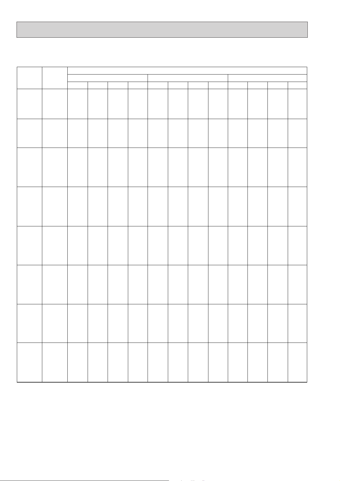
COOLING CAPACITY<3>
Outdoor intake air D.B.(°C)
20 25 30
Indoor
Intake air
D.B.(°C)
Indoor
Intake air
W.B.(°C)
20
20
20
22
22
22
24
24
24
24
26
26
26
26
27
27
27
27
28
28
28
28
30
30
30
30
32
32
32
32
16
18
20
16
18
20
16
18
20
22
16
18
20
22
16
18
20
22
16
18
20
22
16
18
20
22
16
18
20
22
CA
5549
5908
6271
5549
5908
6271
5549
5908
6271
6638
5549
5908
6271
6638
5549
5908
6271
6638
5549
5908
6271
6638
5549
5908
6271
6638
5549
5908
6271
6638
SHC(W)
3274
2777
2195
3718
3249
2696
4161
3722
3198
2589
4605
4195
3700
3120
4827
4431
3951
3385
5049
4667
4202
3651
5493
5140
4703
4182
5549
5612
5205
4713
SHF
0.59
0.47
0.35
0.67
0.55
0.43
0.75
0.63
0.51
0.39
0.83
0.71
0.59
0.47
0.87
0.75
0.63
0.51
0.91
0.79
0.67
0.55
0.99
0.87
0.75
0.63
1.00
0.95
0.83
0.71
SHF
0.59
0.47
0.35
0.67
0.55
0.43
0.75
0.63
0.51
0.39
0.83
0.71
0.59
0.47
0.87
0.75
0.63
0.51
0.91
0.79
0.67
0.55
0.99
0.87
0.75
0.63
1.00
0.95
0.83
0.71
SHF
0.59
0.47
0.35
0.67
0.55
0.43
0.75
0.63
0.51
0.39
0.83
0.71
0.59
0.47
0.87
0.75
0.63
0.51
0.91
0.79
0.67
0.55
0.99
0.87
0.75
0.63
1.00
0.95
0.83
0.71
P.C.
1.82
1.86
1.89
1.82
1.86
1.89
1.82
1.86
1.89
1.93
1.82
1.86
1.89
1.93
1.82
1.86
1.89
1.93
1.82
1.86
1.89
1.93
1.82
1.86
1.89
1.93
1.82
1.86
1.89
1.93
CA
5397
5752
6124
5397
5752
6124
5397
5752
6124
6511
5397
5752
6124
6511
5397
5752
6124
6511
5397
5752
6124
6511
5397
5752
6124
6511
5397
5752
6124
6511
SHC(W)
3184
2704
2143
3616
3164
2633
4048
3624
3123
2539
4479
4084
3613
3060
4695
4314
3858
3320
4911
4544
4103
3581
5343
5004
4593
4102
5397
5465
5083
4623
P.C.
1.90
1.94
1.97
1.90
1.94
1.97
1.90
1.94
1.97
2.01
1.90
1.94
1.97
2.01
1.90
1.94
1.97
2.01
1.90
1.94
1.97
2.01
1.90
1.94
1.97
2.01
1.90
1.94
1.97
2.01
CA
5198
5543
5905
5198
5543
5905
5198
5543
5905
6285
5198
5543
5905
6285
5198
5543
5905
6285
5198
5543
5905
6285
5198
5543
5905
6285
5198
5543
5905
6285
SHC(W)
3067
2605
2067
3483
3049
2539
3899
3492
3012
2451
4315
3935
3484
2954
4523
4157
3720
3205
4731
4379
3956
3457
5146
4822
4429
3960
5198
5266
4901
4462
P.C.
2.04
2.09
2.13
2.04
2.09
2.13
2.04
2.09
2.13
2.18
2.04
2.09
2.13
2.18
2.04
2.09
2.13
2.18
2.04
2.09
2.13
2.18
2.04
2.09
2.13
2.18
2.04
2.09
2.13
2.18
PKH-2GKL
PKH-2GKLH
CA : Capacity (W) SHC(W) : Sensible heat capacity
P.C. : Power consumption (kW) SHF : Sensible heat factor
8
Page 9
COOLING CAPACITY<4>
Outdoor intake air D.B.(°C)
35 40 45
Indoor
Intake air
D.B.(°C)
Indoor
Intake air
W.B.(°C)
20
20
20
22
22
22
24
24
24
24
26
26
26
26
27
27
27
27
28
28
28
28
30
30
30
30
32
32
32
32
16
18
20
16
18
20
16
18
20
22
16
18
20
22
16
18
20
22
16
18
20
22
16
18
20
22
16
18
20
22
CA
4988
5323
5677
4988
5323
5677
4988
5323
5677
6050
4988
5323
5677
6050
4988
5323
5677
6050
4988
5323
5677
6050
4988
5323
5677
6050
4988
5323
5677
6050
SHC(W)
2943
2502
1987
3342
2928
2411
3741
3353
2895
2360
4140
3779
3349
2844
4339
3992
3577
3086
4539
4205
3804
3328
4938
4631
4258
3812
4988
5057
4712
4296
P.C.
2.19
2.24
2.30
2.19
2.24
2.30
2.19
2.24
2.30
2.35
2.19
2.24
2.30
2.35
2.19
2.24
2.30
2.35
2.19
2.24
2.30
2.35
2.19
2.24
2.30
2.35
2.19
2.24
2.30
2.35
CA
4765
5093
5440
4765
5093
5440
4765
5093
5440
5806
4765
5093
5440
5806
4765
5093
5440
5806
4765
5093
5440
5806
4765
5093
5440
5806
4765
5093
5440
5806
SHC(W)
2811
2394
1904
3192
2801
2339
3574
3208
2774
2264
3955
3616
3209
2729
4145
3820
3427
2961
4336
4023
3645
3193
4717
4431
4080
3658
4765
4838
4515
4122
P.C.
2.34
2.40
2.46
2.34
2.40
2.46
2.34
2.40
2.46
2.53
2.34
2.40
2.46
2.53
2.34
2.40
2.46
2.53
2.34
2.40
2.46
2.53
2.34
2.40
2.46
2.53
2.34
2.40
2.46
2.53
CA
4530
4852
5193
4530
4852
5193
4530
4852
5193
5552
4530
4852
5193
5552
4530
4852
5193
5552
4530
4852
5193
5552
4530
4852
5193
5552
4530
4852
5193
5552
SHC(W)
2673
2281
1818
3035
2669
2233
3397
3057
2648
2165
3760
3445
3064
2610
3941
3639
3272
2832
4122
3833
3479
3054
4484
4221
3895
3498
4530
4610
4310
3942
P.C.
2.49
2.55
2.63
2.49
2.55
2.63
2.49
2.55
2.63
2.71
2.49
2.55
2.63
2.71
2.49
2.55
2.63
2.71
2.49
2.55
2.63
2.71
2.49
2.55
2.63
2.71
2.49
2.55
2.63
2.71
SHF
0.59
0.47
0.35
0.67
0.55
0.43
0.75
0.63
0.51
0.39
0.83
0.71
0.59
0.47
0.87
0.75
0.63
0.51
0.91
0.79
0.67
0.55
0.99
0.87
0.75
0.63
1.00
0.95
0.83
0.71
SHF
0.59
0.47
0.35
0.67
0.55
0.43
0.75
0.63
0.51
0.39
0.83
0.71
0.59
0.47
0.87
0.75
0.63
0.51
0.91
0.79
0.67
0.55
0.99
0.87
0.75
0.63
1.00
0.95
0.83
0.71
SHF
0.59
0.47
0.35
0.67
0.55
0.43
0.75
0.63
0.51
0.39
0.83
0.71
0.59
0.47
0.87
0.75
0.63
0.51
0.91
0.79
0.67
0.55
0.99
0.87
0.75
0.63
1.00
0.95
0.83
0.71
PKH-2GKL
PKH-2GKLH
CA : Capacity (W) SHC(W) : Sensible heat capacity
P.C. : Power consumption (kW) SHF : Sensible heat factor
9
Page 10
Cooling capacity correction factors
15
20
25
15
20
25
CA
3,184
3,049
2,930
4,280
4,098
3,939
P.C.
1.01
1.09
1.15
1.56
1.68
1.79
CA
3,650
3,506
3,364
4,905
4,713
4,521
P.C.
1.12
1.20
1.28
1.73
1.86
1.98
CA
4,160
4,003
3,844
5,591
5,380
5,167
P.C.
1.23
1.32
1.42
1.90
2.05
2.19
CA
4,714
4,538
4,370
6,336
6,100
5,874
P.C.
1.35
1.45
1.56
2.09
2.25
2.41
CA
5,312
5,112
4,942
7,139
6,871
6,643
P.C.
1.48
1.59
1.70
2.28
2.46
2.64
CA
5,952
5,724
5,560
8,000
7,693
7,473
P.C.
1.61
1.73
1.86
2.49
2.68
2.87
-10 -5 0Service Ref.
Indoor
intake
air
D.B.(˚C)
PKH-1.6GKL
PKH-1.6GKLH
PKH-2GKL
PKH-2GKLH
5
Outdoor intake air W.B.(˚C)
10 15
Service Ref.
PKH-1.6GKL
PKH-1.6GKLH
PKH-2GKL
PKH-2GKLH
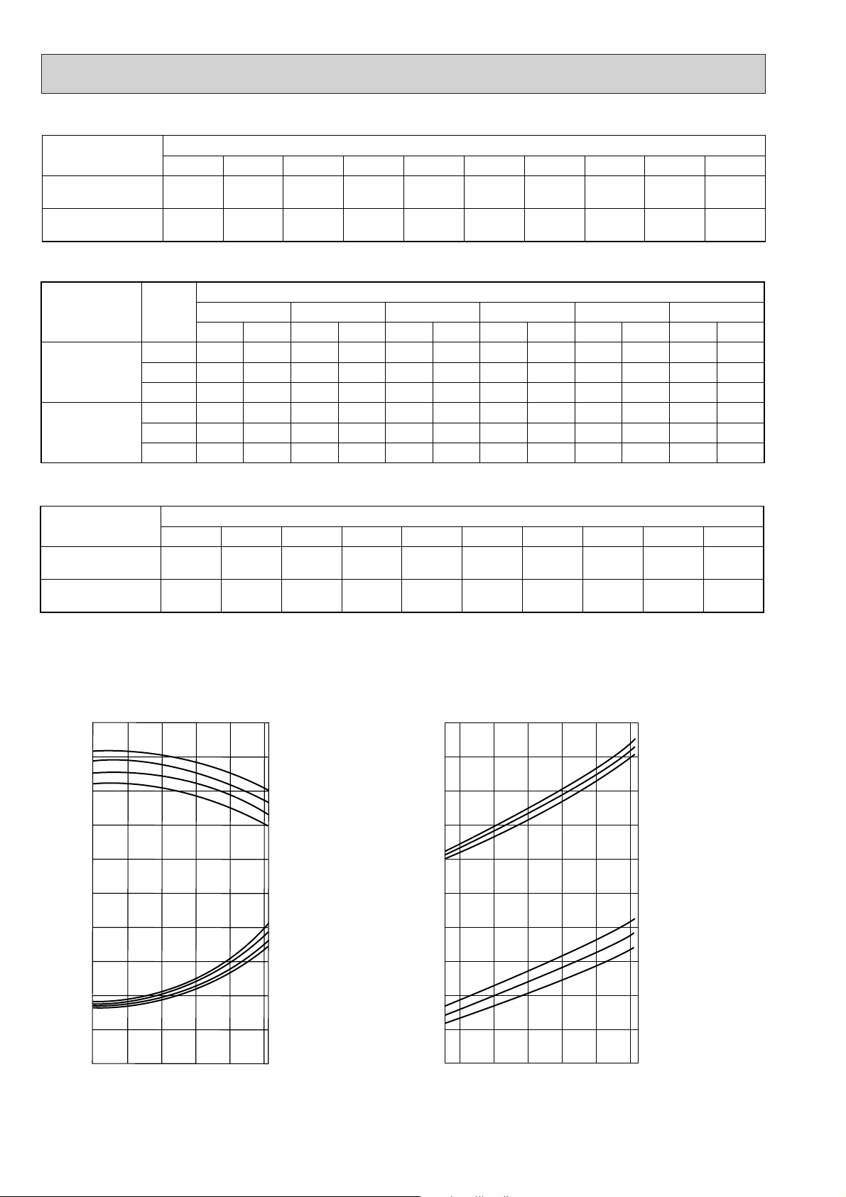
Refrigerant piping length(one way)
5m 10m 15m 20m 25m 30m 35m 40m 45m 50m
1.00
1.00
1.00
1.00
1.00
1.00
1.00
1.00
1.00
1.00
1.00
1.00
0.998
0.998
0.995
0.995
—
—
—
—
1.4
1.2
1.0
0.8
0.6
1.4
1.2
1.0
0.8
0.6
0.4
-5 5 15 253546
OUTDOOR D.B.(°C)
TOTAL INPUT (RATIO) CAPACITY (RATIO)
INDOOR W.B.(°C)
INDOOR W.B.(°C)
22
20
18
16
22
20
18
16
1.4
1.2
1.0
0.8
0.6
1.4
1.2
1.0
0.8
0.6
0.4
-12-10 -5 0 5 10 15
OUTDOOR W.B. (°C)
INDOOR D.B. (°C)
INDOOR D.B. (°C)
15
20
25
25
20
15
TOTAL INPUT (RATIO) CAPACITY (RATIO)
Service Ref.
PKH-1.6GKL
PKH-1.6GKLH
PKH-2GKL
PKH-2GKLH
5m 10m 15m 20m 25m 30m 35m 40m 45m 50m
1.00
1.00
0.993
0.992
2) HEATING CAPACITY
Heating capacity correction factors
0.984
0.983
Refrigerant piping length(one way)
0.978
0.978
0.969
0.966
0.961
0.959
0.956
0.950
0.948
0.945
CA : Capacity (W)
P.C. : Power consumption (kW)
—
—
—
—
2. PERFORMANCE CURVE
Cooling
10
Heating
Page 11
Service Ref.
Indoor unit
Outdoor unit
PKH-1.6GKL
PKH-1.6GKLH
PUH-1.6VKA
2
Cool
4,400
1.43
0.07
0.33
0.40
1.36
6.79
30
4,550
(5,220)
1.39
(2.06)
0.07
(0.74)
0.33
(3.38)
0.40
(3.45)
Heat
1.32
6.59
30
6,150
(6,820)
2.21
(2.88)
0.07
(0.74)
0.33
(3.38)
0.40
(3.45)
Cool
5,400
2.19
0.07
0.33
0.40
2.12
9.83
43
Heat
2.14
9.93
43
PKH-2GKL
PKH-2GKLH
PUH-2VKA
2
Outdoor
unit
Indoor
unit
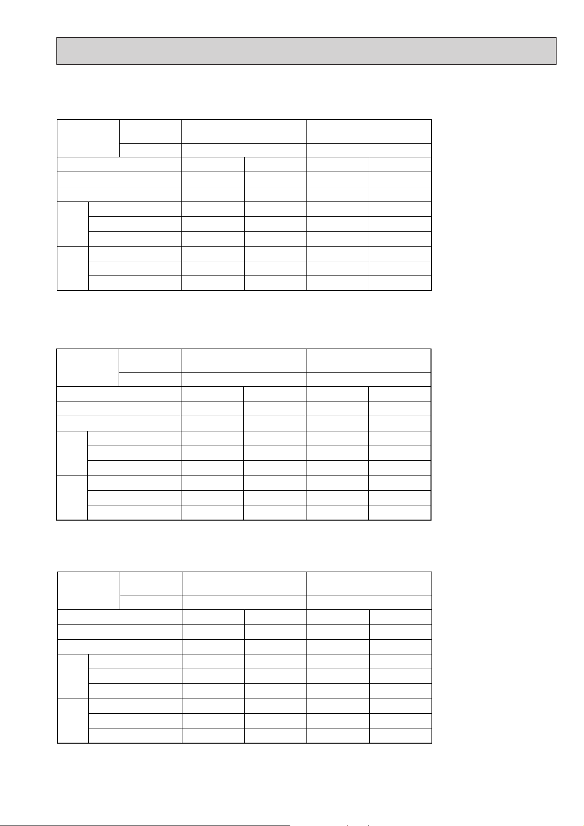
Mode
Capacity(W)
Total Input(kW)
Input(kW)
Current(A)
Starting current(A)
Input(kW)
Current(A)
Starting current(A)
3. ELECTRICAL DATA
Indoor unit· · · · · 220V 50Hz 1phase
Outdoor unit · · · 220V 50Hz 1phase
w : ( ) shows the heater on rating.
Indoor unit· · · · · 230V 50Hz 1phase
Outdoor unit· · · · 230V 50Hz 1phase
w : ( ) shows the heater on rating.
Indoor unit· · · · · 240V 50Hz 1phase
Outdoor unit· · · · 240V 50Hz 1phase
w : ( ) shows the heater on rating.
Service Ref.
Mode
Capacity(W)
Total Input(kW)
Input(kW)
Current(A)
unit
Indoor
Starting current(A)
Input(kW)
Current(A)
unit
Outdoor
Starting current(A)
Service Ref.
Mode
Capacity(W)
Total Input(kW)
Input(kW)
Current(A)
unit
Indoor
Starting current(A)
Input(kW)
Current(A)
unit
Outdoor
Starting current(A)
Indoor unit
Outdoor unit
Indoor unit
Outdoor unit
PKH-1.6GKL
PKH-1.6GKLH
PUH-1.6VKA
Cool
4,450
1.47
0.07
0.33
0.40
1.40
6.76
32
PKH-1.6GKL
PKH-1.6GKLH
PUH-1.6VKA
Cool
4,500
1.51
0.07
0.33
0.40
1.44
6.74
33
2
Heat
4,600
(5,330)
1.43
(2.16)
0.07
(0.80)
0.33
(3.50)
0.40
(3.57)
1.36
6.57
32
2
Heat
4,650
(5,450)
1.48
(2.28)
0.07
(0.87)
0.33
(3.66)
0.40
(3.73)
1.41
6.60
33
5,450
11
PKH-2GKL
PKH-2GKLH
PUH-2VKA
Cool
2.23
0.07
0.33
0.40
2.16
9.78
44
PKH-2GKL
PKH-2GKLH
PUH-2VKA
Cool
5,500
2.27
0.07
0.33
0.40
2.20
9.86
45
2
Heat
6,200
(6,930)
2.25
(2.98)
0.07
(0.80)
0.33
(3.50)
0.40
(3.57)
2.18
9.87
44
2
Heat
6,250
(7,050)
2.29
(3.09)
0.07
(0.87)
0.33
(3.66)
0.40
(3.73)
2.22
9.95
45
Page 12
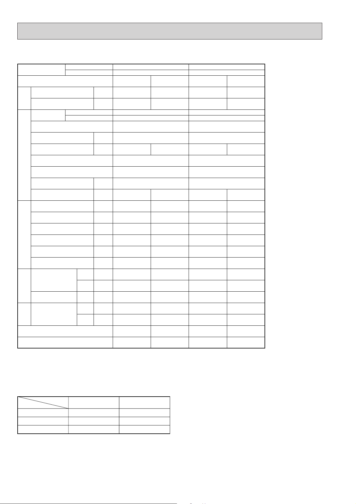
4. STANDARD OPERATION DATA
Service Ref.
Without electric heater
With electric heater
Capacity W
Input
Indoor unit
Service Ref.
Without electric heater
With electric heater
Phase, Hz
Volts
Amperes
Outdoor unit Service Ref.
Phase,Hz
Volts
Amperes
Discharge pressure
Suction pressure
Discharge temperature
Condensing temperature
kW
V
A
V
A
MPa
(
kg/cm
MPa
(
kg/cm
˚C
˚C
PKH-1.6GKL
PKH-1.6GKLH
CoolingMode
4,500
1.51
Heating
4,650
[5,450]
1.48
[2.28]
PKH-1.6GKL
PKH-1.6GKLH
1, 50
240
0.33
PUH-1.6VKA
0.33
[3.66]
2
1, 50
240
6.74
1.77
2
)
(
)
18.0
0.54
2
)
(
)
5.5
79
47
6.60
1.85
(18.8)
0.41
(
4.2
83
48
)
PKH-2GKL
PKH-2GKLH
Cooling Heating
5,500
2.27
6,250
[7,050]
2.29
[3.09]
PKH-2GKL
PKH-2GKLH
1, 50
240
0.33
PUH-2VKA
0.33
[3.66]
2
1, 50
240
9.86 9.95
1.92
(19.6)
0.46
(
4.7
)
2.08
(21.2)
0.37
(3.8)
87 93
51 54
Suction temperature
Ref.pipe length
Intake air
temperature
Discharge air
Indoor side Refrigerant circuit Electrical circuit Total
temperature
Intake air
temperature
side
Outdoor
SHF
BF
D.B.
W.B.
D.B.
D.B.
W.B.
˚C
˚C
˚C
˚C
˚C
˚C
8
m
5
27
19
13.3
35
24
0.76
0.10
0.6
5
20
15
39.2
7
6
-
-
4–2
55
27 20
19 15
11.7 45.4
35 7
24 6
0.69
0.12
-
-
The unit of pressure has been changed to Mpa on the international system of unit (SI unit system).
The converted score against the traditional unit system can be gotten according to the formula below.
1(Mpa) = 10.2(kg/FF)
5. OUTLET AIR SPEED AND COVERAGE RANGE
Service Ref.
Item
Air flow m3/
Air speed m/
min
sec
Coverage range m (ft)
The air coverage range is the value up to the position where the air speed is 0.25m/sec. when air is blown out horizontally from
the unit at the Hi notch position.
The coverage range should be used only as a general guideline since it varies according to the size of the room and the furniture inside the room.
PKH-1.6GKL
PKH-1.6GKLH
12
5.3
10(32.8)
PKH-2GKL
PKH-2GKLH
12
5.3
10(32.8)
12
Page 13
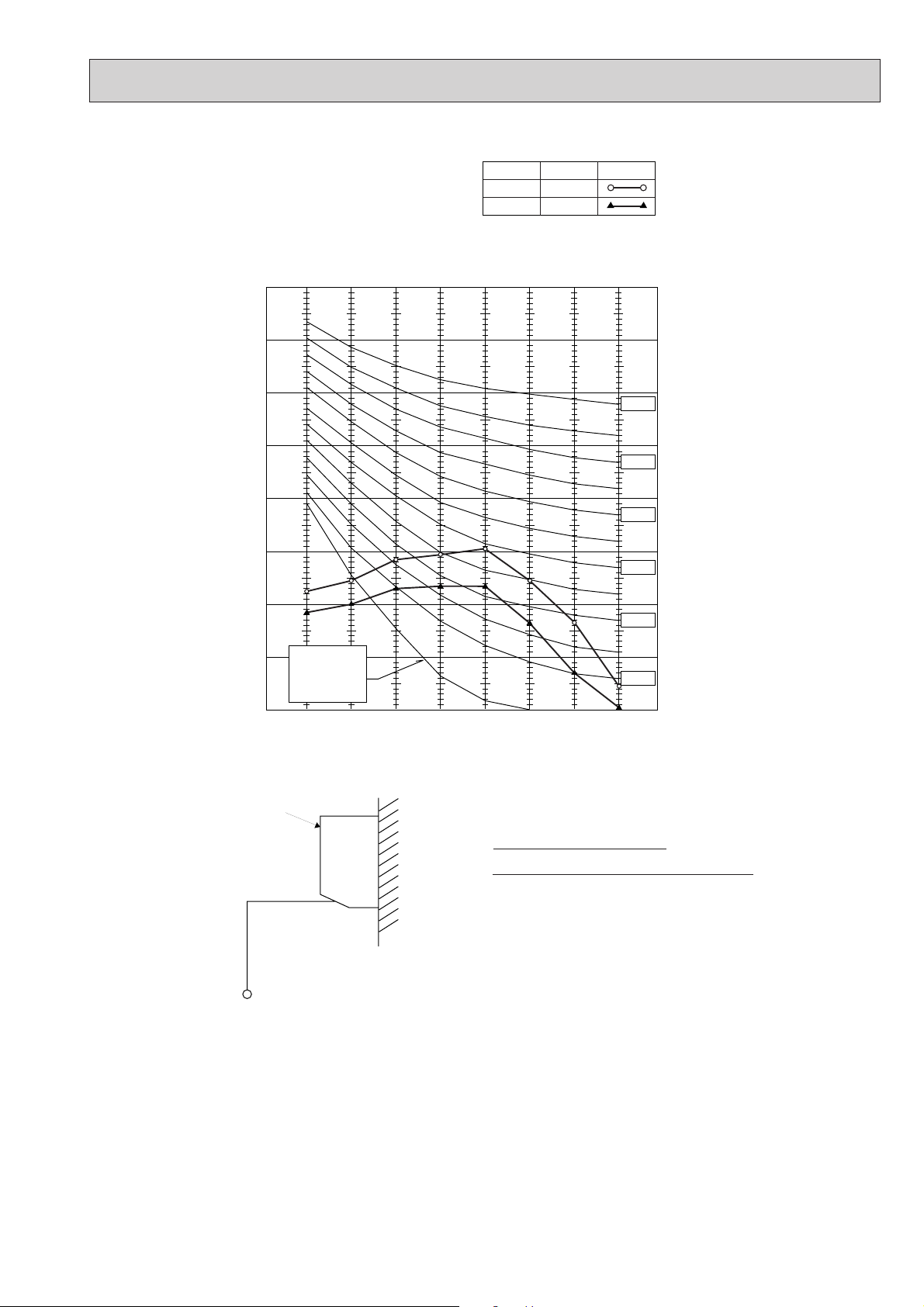
6. NOISE CRITERION CURVES
UNIT
WALL
1m
1m
MICROPHONE
Ambient temperature 27:
Test conditions are based on JIS Z8731
PKH-1.6/2GKL
PKH-1.6/2GKLH
90
80
70
60
50
40
30
OCTAVE BAND SOUND PRESSURE LEVEL, dB re 0.002 MICRO BAR
20
10
APPROXIMATE
THRESHOLD OF
REARING FOR
CONTINUOUS
NOISE
63 125 250 500 1000 2000 4000 8000
BAND CENTER FREQUENCIES, Hz
NOTCH
Hi
Lo
SPL(dB)
43
36
LINE
NC-70
NC-60
NC-50
NC-40
NC-30
NC-20
13
Page 14
4
BYOFF
ONSTAND
HEATCOOL
OFF BY
ON STAND
COOL HEAT
ÅrÇoÇoÅqÅ@ëOñÅ@ÇeÇqÇnÇmÇs ÅrÇoÇoÅqÅ@ëOñÅ@ÇeÇqÇnÇmÇs
r.SLI
m m
MITSUBISHI ELECTRICMITSUBISHI ELECTRIC
r.SLI
m m
MITSUBISHI ELECTRICMITSUBISHI ELECTRIC
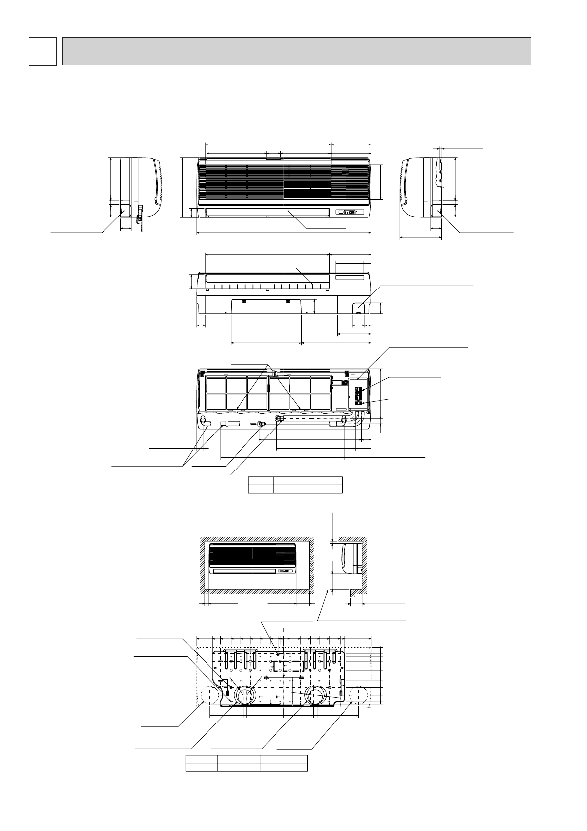
21
Right side
Less than 15
70
245
60
235
Auto vane
Front view
198 Air intake
53
340
715 Air intake 225
340 Air intake 80 280 Air intake 233
990
21
Left side
Knock out hole
for left piping.
Refrigerant pipe.
Drain pipe.
Wiring hole.
Knock out hole
for left piping.
Refrigerant pipe.
Drain pipe.
Wiring hole.
60
70
245
(Necessary clearance for
Unit installation)
Right side
Allowing clearances
Front view
Less than 130
50 or more 150 or more
180 or more
30 or more
for bolts
Left-rear
piping hole
left-rear piping
R52.5
R52.5
Installation plate
balance point hole
Details of installation plate
49-[5hole
for tapping screw
Knock out hole for
right-rear piping
Right-rear
piping hole
Unit center
14-[14hole
Knock out hole for
425
420
170
190
210
230
0
322
0
35
55
80
130
190
230
272
310
0
3595150
205
260
320
345
495
20
75
135
190
245
300
360
405
495
32
0
w1 Sleeves are available on the market.
w2 This size shows the lower end of through hole.
[90~[100[90
Through holeSleeve w1
1.6 . 2
Model
R52.5
R52.5
Gas pipe
Liquid pipe
Terminal block for
Terminal block to
outdoor unit
Filter grip
Service panel
(Power supply access)
5/8F
Gas pipeLiquid pipe
3/8F1.6 . 2
Model
(Right side piping
installation)
(Left side piping
installation)
Unit drain pipe O.D.20
Front view(to open the grille)
700 (Flexible hose total length800)
581
86
449
54
31 280
35
Knock out hole for under piping
Refrigerant piping.Drain pipe.
Wiring hole
12-Louvers(manual)
Lower side
80
50
395400
190
60
70 35
79
160
40
235
705 Air outlet
power supply
153
w2
OUTLINES AND DIMENSIONS
1. INDOOR UNIT
PKH-1.6GKL / PKH-2GKL
PKH-1.6GKLH / PKH-2GKLH
Unit : mm
14
Page 15
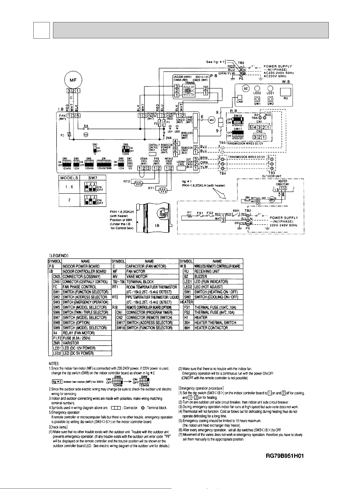
5
PKH-1.6GKL / PKH-2GKL
PKH-1.6GKLH / PKH-2GKLH
WIRING DIAGRAM
15
Page 16
6
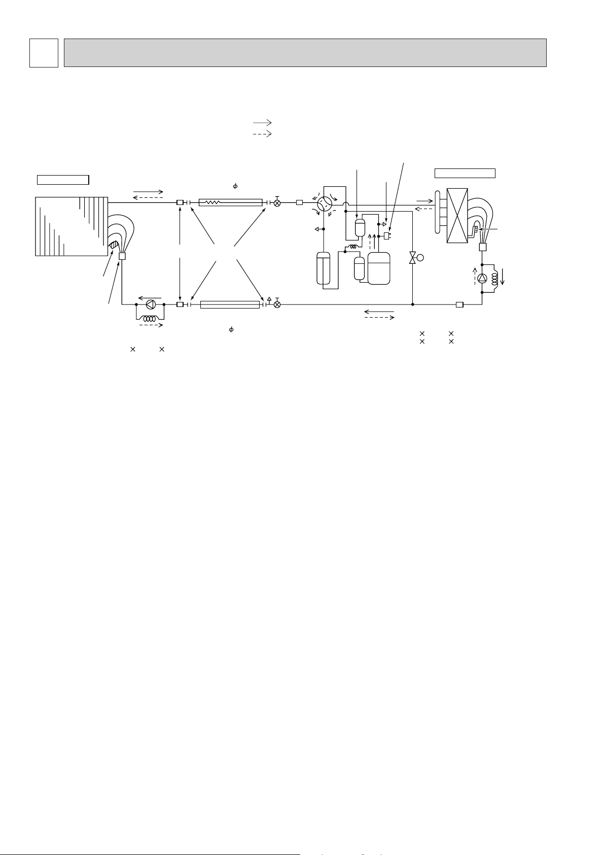
REFRIGERANT SYSTEM DIAGRAM
PKH-1.6GKL, PKH-1.6GKLH / PUH-1.6VKA2
PKH-2GKL, PKH-2GKLH / PUH-2VKA2
Refrigerant pipe
Indoor unit
Indoor
heat
exchanger
Pipe
temperature
thermistor
(RT2)
Distributor
with
strainer
PKH-1.6, 2 (O.D.3.2 I.D.1.8 L500)
Restrictor
valve
Capillary
tube
Strainer
(option)
15.88mm( 5/8")
(with heat insulator)
Flexible tube
Flared
connection
Refrigerant pipe
(option)
9.52mm( 3/8")
(with heat insulator)
Ball
valve
Ball valve
(with Service port)
Refrigerant flow in cooling
Refrigerant flow in heating
Oil separator
Service
port
Compressor
PUH-1.6 (O.D.3.2 I.D.1.8 L400)
PUH-2 (O.D.4.0 I.D.2.0 L430)
Strainer
Service
port
Accumulator
4-way valve
<4-Way valve solenoid coil>
Heating ON
Cooling OFF
High pressure
control switch
Outdoor unit
Outdoor heat exchanger
Bypass
valve
Restrictor
valve
Strainer
Unit : mm
Outdoor coil
thermistor
(TH)
Capillary
tube
16
Page 17
7
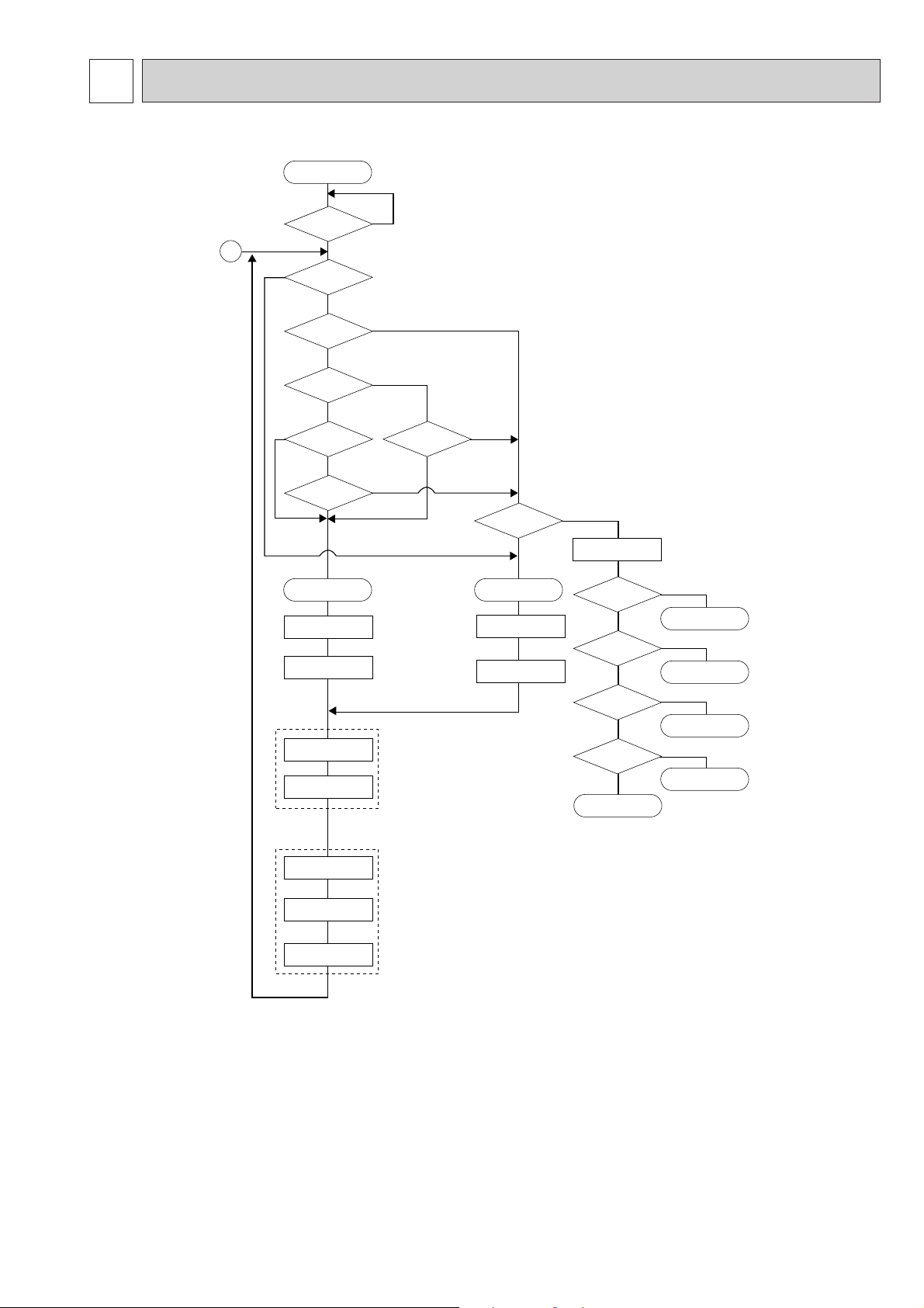
OPERATION FLOW-CHART
MAIN OPERATION
START
YES
NO
NO
NO
YES
NO
NO
w 1
YES
YES
YES
w 4
Set time
complete
YES
NO
w 2
Trouble
Trouble STOP
PROTECTION DEVICE
SELF HOLD
Remote controller
trouble display
NO
YES
w 3
Remote controller
operation display
Operating mode
(COOL)
NO
Operating mode
(DRY)
NO
Operating mode
(HEAT)
w 6
NO
Operating mode
(FAN)
NO
Auto COOL/HEAT
operation
YES
COOL operation
YES
DRY operation
YES
HEAT operation
YES
FAN operation
w 7
Power circuit
breaker
1
YES
Check SW
ON twice
Operation SW
ON
“OFF” timer
NO
“ON” timer
Set time
complete
STOP
PROTECTION DEVICE
SELF HOLD RELEASE
Remote controller
indicator lamp OFF
Indoor side
Fan STOP
Auxiliary heater OFF
Outdoor side
Compressor OFF
Fan STOP
Four-way valve OFF
w 5
w1 In addition, the centralized control and remote control can be operated.
w2 The modes which indicate the sources of trouble are listed below.
● EO-Signal transmitting/receiving error
● P1-Room temperature thermistor malfunction
● P2-Pipe temperature thermistor malfunction
● P4-Drain sensor malfunction
● P5-Drain overflow
● P6-Coil frost/overheat protection
● P7-System error
● P8-Outdoor unit trouble
w3 The CHECK switch will show if an error has occurred in the past.
w4 Fan runs on low speed for 1 minute in order to remove overheat air.
w5 The 3-minute (6 minutes …heating mode) time-delay functions after compressor stops.
w6 FAN or AUTO mode is selected by the indoor dip switch setting.
w7 In FAN mode, fan speed and vane operation depend on the remote controller setting. (Compressor is OFF.)
17
Page 18
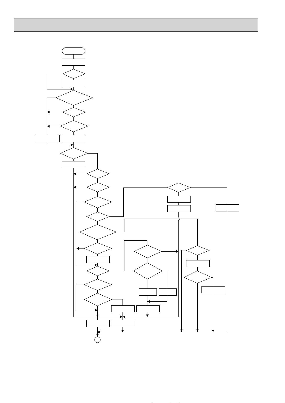
COOLING OPERATION
COOL operation
Four-way valve/OFF
NO
NO
NO
NO
Vane setting notch
Initial
COOLING
w 8
50 deg downward angle
60 deg downward angle
Vane horizontal
w 9
YES
Vane initial
setting
Vane
YES
Fan speed
LOW
YES
Downward discharge
1 hour
YES
airflow
Compressor
thermostat
Allowance
cancel
ON
NO
NO
YES
YES
NO
w 11
YES
compressor operation
w 10
Cooling area
3-minute
time delay
time delay
3-minute
Coil frost
protection
NO
6-minute
NO
YES
NO
YES
NO
Allowance
period
NO
6 minute
time delay
Allowance set
YES
Coil frost protection
YES
10-minute
NO
compressor operation
Allowance cancel
Coil frost
prevention
NO
16-minute
NO
compressor operation
YES
Indoor pipe
temperature is
1°C or lower
NO
Compressor ON
1
YES
YES
YES
Coil frost
prevention
Compressor OFF
Pipe
YES
YES
NO
NO
3-minute
time delay
temperature is
10°C or higher
Defrosting protection
detection temperature
-1°C or lower
6-minute
time delay
Coil frost
prevention release
NO
1 min continue
FAN speed
LOW
FAN speed
LOW 5 min
elapse
YES
NO
Outdoor unit
YES
trouble
w8 When operation stops or changes to cooling or dry mode, the auto vane turns to a horizontal angle. If operation changes
during auto vane SWING, the auto vane will continue to swing.
w9 When operating TEST RUN, the thermostat will be continuously ON.
w10 After 3 minute compressor operation, if the pipe temperature thermistor reads -15°C or below for 3 minutes, the compres-
sor will stop for 6 minutes.
w11 Heating area : Pipe temperature is more than 5 degrees above the room temperature.
Cooling area : Pipe temperature is more than 5 degrees below the room temperature.
FAN area : Pipe temperature is within 5 degrees either way of the room temperature.
18
Page 19
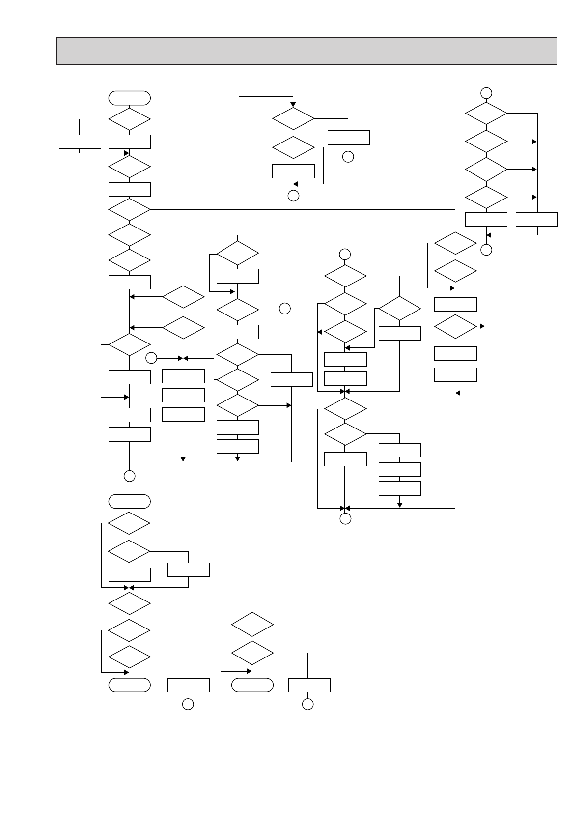
HEATING OPERATION
Heat operation
YES
NO
NO
NO
YES
w 11
YES
YES
w 10
NO
Heating area
NO
Defrost
30 min. elapse
YES
Outdoor unit trouble
1
A
Outdoor unit
trouble
NO
Vane setting notch
Vane initial setting
Four-way valve ON
w 9
Allowance cancel
NO
Very low airflow
Compressor OFF
AUTOMATIC COOLING/HEATING OPERATION
NO
w 17
w 15
initial
HEATING
YES
NO
defrosting
NO
Hot adjust
in process
NO
Compressor ON
NO
Compressor
thermostat ON
NO
Indoor piping
-15°C or lower
trouble
1
>
=
2
w 16
YES
NO
YES
YES
Outdoor unit
FAN SPEED
Auto COOL/HEAT
operation
Initial mode
T1 To
COOL mode
YES
YES
YES
YES
YES
3 min.restart
prevention
NO
YES
6 min. restart
prevention
NO
Hot adjust start
FAN SPEED very low
Compressor ON
HEAT mode
10-minute
NO
compressor
operation
Allowance cancel
w 11
Heating
area
FAN STOP
w 11
FAN area
20 min.elaspe
YES
FAN area
Heating area
w 11
FAN area
Cooling area
Defrost operation
START
Four-way valve
OFF
YES
Defrost release
NO
B
Indoor piping
55°C or lower
NO
Auxiliary heater
ON
NO
Indoor piping
60°C or higher
YES
Auxiliary heater OFF
Overheat remote
START
NO
Indoor unit
70°C or higher
Allowance
period
Overload protect
1
2
NO
YES
YES
YES
YES
NO
Auxiliary heater
thermostat ON
Auxiliary heater ON
NO
6-minute restart
prevention
Allowance set
Compressor OFF
YES
YES
FAN SPEED
FAN SPEED
setting notch
Hot adjust
Airflow 10% up
Indoor piping
35°C or higher
NO
HOT adjust
5 min. elapse
YES
Low
FAN SPEED
Low 2 min.
elapse
YES
release
A
PKH-GKLH
Type
YES
3-minute
Auxiliary heater
OFF
YES
Pipe temperature
is 60°C or higher
YES
FAN speed
Low notch
YES
B
NO
NO
NO
NO
NO
NO
FAN setting notch
YES
YES
NO
NO
YES
HEAT operation
1
NO
T1 ] (To + 2)
After 15min.
T1 ] (To + 2)
HEAT operation
YES
NO
YES
Cool mode
set
1
COOL mode
NO
T1 [ (To - 2)
After 15min.
T1 [ (To-2)
COOL operation
w15 ( i ) Until Low airflow is set while in hot adjustment
(ii)While defrosting (FAN STOP)
(iii)When thermostat is OFF
In the case of( i ), (ii) and (iii) above, airflow is horizontal regardless the VANE setting.
w16 When AUTO operation is started, COOLor HEAT mode is selected automatically.
w17 T1 : Room temperature.
To : Set temperature.
19
Page 20
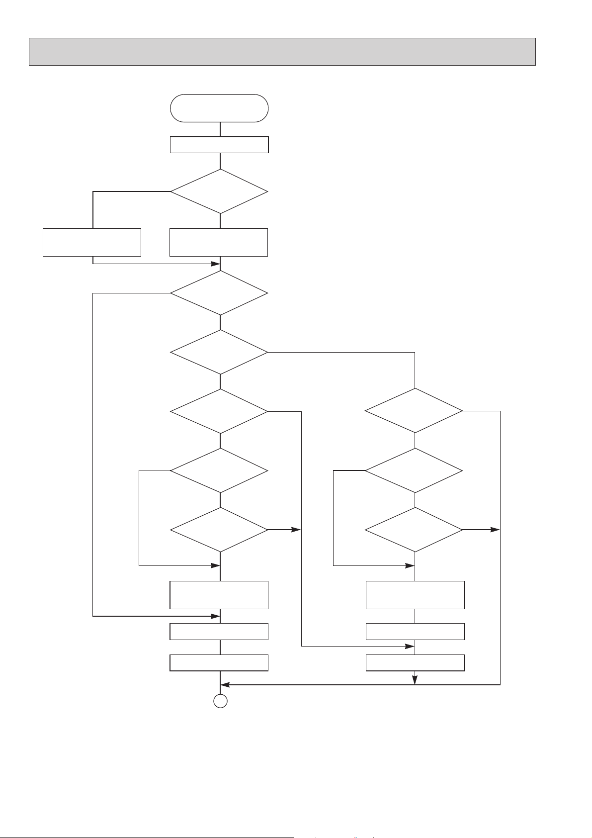
DRY OPERATION
DRY
operation
Four-way valve / OFF
Vane
setting notch
NO
YES
NO
Initial dry
operation
YES
Vane initial setting
w12
Room temperature is
18°C or lower
NO
During
compressor ON
YES
3-minute
compressor
operation
YES
Compressor &
thermostat ON
YES
w8
w9
NO
NO
YES
3-minute
time delay
NO
Compressor &
thermostat
ON
NO
YES
w9
Compressor ON
time completes
YES
10-minute compressor
OFF timer start
Compressor OFF
Fan STOP
1
w8~9 Refer to page 26~27.
w12 When room temperature is 18°C or below, the compressor cannot operate.
When room temperature rises over 18°C, the compressor starts after a 3-minute time delay.
w13 Compressor ON time is decided by room temperature. Refer to page 26~27.
w14 In dry operation, compressor ON makes the fan speed LOW. Also, when the compressor OFF and the pipe temperature
is 26°C or less, the fan stops, or when the compressor OFF and the pipe temperature is below 6°C, the fan speed
changes to LOW mode.
It is not possible to set the fan speed with the remote controller
NO
w14
10-minute
compressor
OFF
YES
Compressor ON
time set
Compressor ON
Fan speed LOW
NO
w13
w14
20
Page 21
8
ON/OFF
CHECK
ADDRESS
UNIT No.
FUNCTION No.
SELECTION No.
AM
PM
AM
PM
TEST RUN
FUNCTION
˚C
TEMP.
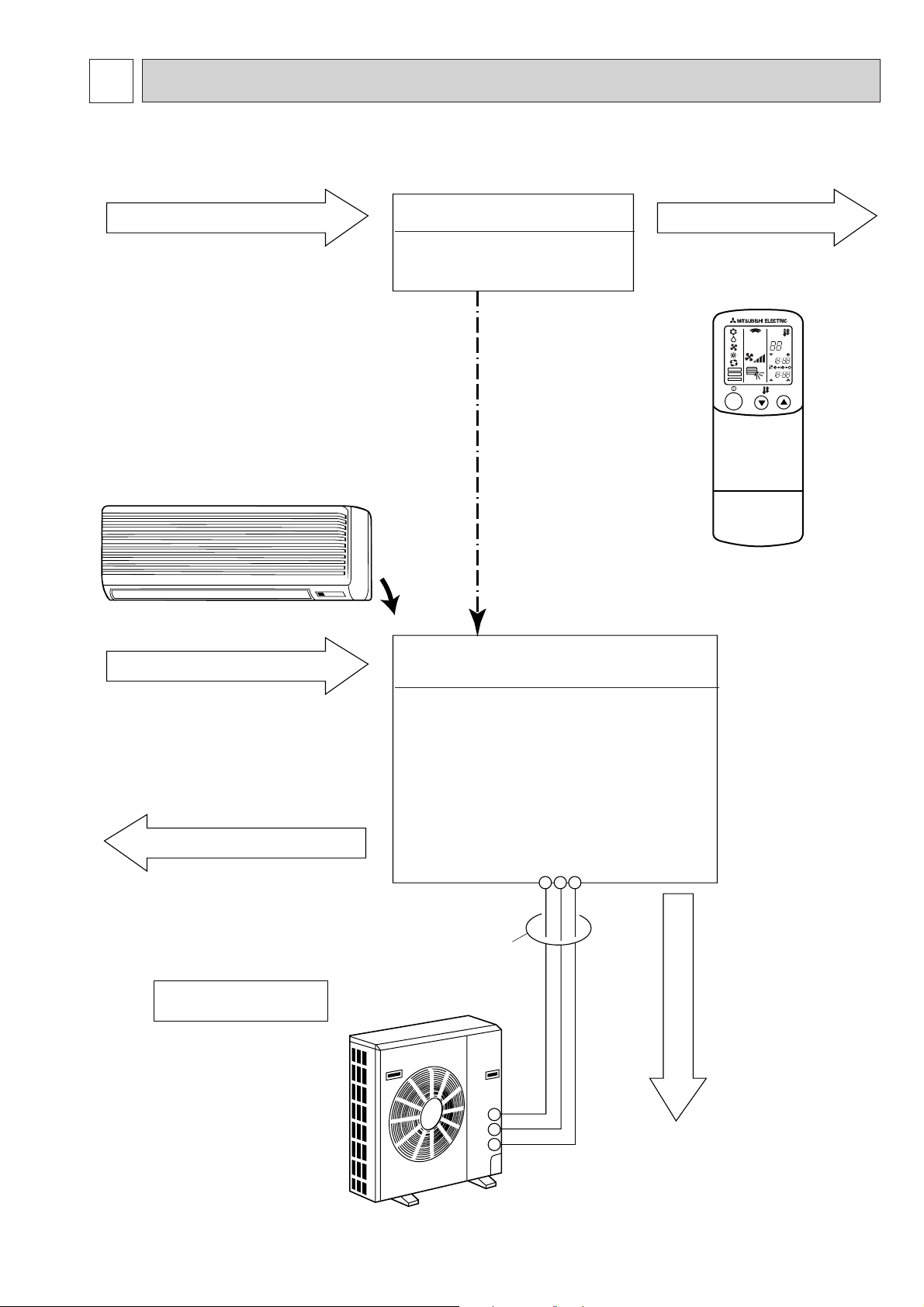
MICROPROCESSOR CONTROL
1. OUTLINE OF MICROPROCESSOR CONTROL
INPUT to remote controller
● OFF-ON switching.
● COOL/DRY-AUTO-HEAT selector switching.
● Thermostat setting.
● TIMER mode selector-switching and Timer
setting.
● HIGH-LOW fan speed switching.
● AUTO Vane selector (AIR DISCHARGE)
switching.
● TEST RUN switching.
● CHECK mode switching.
(Self diagnostic trouble shooting)
Indoor
unit
Remote controller board
● Processes and transmits
orders.
Non-polar, two-wire
cable maximum
length 500 meters
(WIRED only)
Signal
12VDC
OUTPUT to remote controller
Remote controller
● LCD indicator
INPUT from indoor unit
● Room temperature thermistor (RT1)
● Pipe temperature thermistor (RT2)
OUTPUT to indoor unit
● Auto vane’s angle setting.
● Booster heater ON-OFF Control.
● Emergency stop.
Independent Control of
Outdoor Unit
● Compressor protection
device working
● Defrosting
START-STOP
● Fan speed control.
● Crankcase heater control
ON-OFF.
● Self diagnostic function
Indoor controller board
● Receives orders from remote controller and
temperature data from indoor unit.
● Processes orders and data.
● Controls indoor and outdoor operation.
● Self diagnostic function.
w System control operation.
w Emergency operation.
w Set by dip switch on indoor controller board.
● Transmits the power to remote controller.
123
Polar three-wire cable
Outdoor unit
12VDC
1
2
3
● Compressor and
outdoor fan : ONOFF.
● Operation mode
OUTPUT to outdoor unit
change :COOLHEAT.
21
Page 22

Minimum 3 minutes w1
ON
Thermostat
Indoor fan
Auto vane
Booster heater
Compressor
ON
LOW or HIGH
Initally 10 degrees
(Changeable by remote controller setting)
LOW or HIGH
ON
ON
OFF
OFF
CLOSE CLOSE
OFF
OFF
OFF
Operation starts by
POWER button
ON.
Operation stops by
POWER button
OFF.
Room temperature
becomes equal to
set temperature.
Room temperature
rises above set
temperature.
ON/OFF
CHECK
ADDRESS
UNIT No.
FUNCTION No.
SELECTION No.
AM
PM
AM
PM
TEST RUN
FUNCTION
˚C
TEMP.
2. INDOOR UNIT CONTROL
2-1 COOL operation
<COOL operation time chart>
<How to operate>
1 Press POWER ON/OFF button.
2 Press the MODE button to display “
f ”.
3 Press the i TEMP. button to set the desired temperature.
NOTE: The set temperature changes 1°C when the or
button is press one time Cooling 19 to 30°C.
W1 Even if the room temperature rise above the set temperature during this period, the compressor will not start until this period
has ended.
(1) Compressor control
1 3-minute time delay
To prevent overload, the compressor will not start within 3 minutes after stop.
2 The compressor runs when room temperature is higher than set temperature.
The compressor stops when room temperature is equal to or lower than the set temperature.
The compressor maintains the previous state when the discharge temperature minus the set temperature is 0°C or more, or
lower than 1°C.
3 The compressor stops in check mode or during protective functions.
4 Coil frost prevention
To prevent indoor coil frost, the compressor will stop when the indoor coil thermistor (RT2) reads 1°C or below after the
compressor has been continuously operated for at least 16 minutes or more. When the indoor coil temperature rises to
10°C or above, the compressor will start in a 3-minute(w2) time delay.
w2 When the indoor coil temperature is -1°C or less, the compressor starts in 6 minutes.
NOTE : By turning OFF the dip switch SW1-3 on indoor controller board, the start temperature of coil frost prevention changes
from 1°C to -3°C.
22
Page 23

(2) Indoor fan control
5 minutes
SET
LOW
12 13
5 minutes
SET
LOW
OFF
Indoor fan speed LOW/HIGH depends on the remote controller setting.
However, if an outdoor unit abnormality is detected, the indoor fan speed will be LOW, regardless of the remote controller
setting.
(i ) Fan speed LOW/HIGH depends on the remote controller setting regardless of the thermostat ON/OFF.
(ii) Fan speed will remain on LOW if an abnormality in outdoor unit is detected. (5 minutes)
When the abnormality detection is released, the fan speed returns to the set speed.
1 Start-up of outdoor unit abnormality detec-
tion.
2 Release of outdoor unit abnormality detec-
tion.
3 Unit stop due to outdoor unit abnormality
with P8 indication.
NOTE 1 : Fan stops immediately if the unit stops or the check mode is started.
(3) Auto vane control
Auto vane position is set to 10 degrees airflow at the start-up of COOL operation. It can then be changed by the remote
controller.
(a) Stop mode (fixed operation)
( i ) At start-up of COOL operation, the auto vane is set to 10 degrees airflow direction.
(ii) Discharge direction can be changed with VANE button.
1 Fan speed : LOW
10°
50°
60°
(SWING)
2 Fan speed : HIGH
10°
30°
50°
60°
(SWING)
(b) SWING mode
( i ) The vane motor turns ON when the SWING mode is selected.The vane motor is continuously ON during SWING
mode.
<VANE POSITION>
1 Fan speed : LOW
10°
50°
60°
Vane is in motion at the angle of 50° or 60°.
(After an hour, the vane is automatically set at the
angle of 10°)
AUTO
RETURN
2 Fan speed : HIGH
10°
30°
50°
60°
when 50 degrees or 60 degrees airflow is selected with the LOW fan speed in COOL operation, “1Hr” will appear right side
of the air direction display. One hour later, the airflow direction returns to 10 degrees automatically and “1Hr” will disappear.
If the airflow direction is set to 10 degrees during “1Hr” indication, the time counting for AUTO RETURN is cancelled.
As for the unit operted with only wired remote controller ,
23
Page 24

<Auto vane drive>
(a) The vane is driven by DC12V motor.
(b) Airflow direction is selected depends on the number of pulse were sent.
(c) Before start driving the auto vane, detect the standard position first, output the number of pulse to each Airflow.
(d) The speed of the auto vane drive for both open and close are set at 200 pulse/sec.
(e) Method of driving the auto vane.
Detecting the standard position:
1
Output 1600 pulse to the opening direction.
Position setting:Output the number of pulse indicated no below chart to the closing direction.
2
Vane drive
Close
Horizontal
Downward A
Downward B
Downward C 362
(4) Detecting abnormalities in the outdoor unit
After the compressor has been continuously operated for 3 minutes, if the difference between the pipe temperature and
room temperature is out of RANGE C for 1 minute, the indoor fan speed will turn to LOW. Five minutes later, if the difference is still out of RANGE C,the outdoor unit is functioning abnormally. Thus, the compressor stops and check code “P8”
appears on remote controller.
RANGE A: Pipe temperature is more than 5 degrees above the room temperature.
RANGE B : Pipe temperature is within 5 degrees either way of the room temperature.
RANGE C : Pipe temperature is more than 5 degrees below the room temperature.
Pipe temperature
minus room temperature
(degree)
+5
RANGE A
The number of pulse output after
detecting the standard position
1600
697
570
465
-5
0
RANGE B
RANGE C
24
Page 25

2-2 DRY operation
Minimum 3 minutes w1
ON
Thermostat
Indoor fan
Auto vane
Booster heater
Compressor
ON
Initally 10 degrees discharge
(
Changeable by remote controller setting
)
LOW speedLOW speed
ON
ON
OFF
OFF
CLOSE
CLOSE
OFF
OFF
OFF
Operation starts by
POWER button
ON.
Operation stops by
POWER button
OFF.
Room temperature
becomes equal to
set temperature.
Room temperature
rises above set
temperature.
ON/OFF
CHECK
ADDRESS
UNIT No.
FUNCTION No.
SELECTION No.
AM
PM
AM
PM
TEST RUN
FUNCTION
˚C
TEMP.
<DRY operation time chart>
<How to operate>
1 Press POWER ON/OFF button.
2 Press the MODE button to display “ e ”.
3 Press the i TEMP. button to set the desired temperature.
NOTE: The set temperature changes 1°C when the or
button is press one time DRY 19 to 30°C.
w1 Even if the room temperature rise above the set temperature during this period, the compressor will not start until this period
has ended.
25
Page 26

(1) Compressor control
Compressor OFF
6°C or more
Below 6°C
STOP
Pipe temp. Fan
LOW
All LOW
Compressor ON
13-minute time delay
To prevent overload, the compressor will not start within 3-minutes after stop.
2The compressor runs when the room temperature is higher than the set temperature.
The compressor stops when the room temperature is equal to or lower than the set temperature.
3The compressor stops in check mode or during protective functions.
4The compressor will not start when the room temperature is below 18°C.
The compressor starts intermittent operation when the power is turned ON with room temperature above 18°C. The compressor ON/OFF time depends on the thermostat ON/OFF and the following room temperatures.After 3-minute compressor operation,
● If the room temperature thermistor reads above 28°C with thermostat ON, the compressor will operate for 6 more minutes
and then stop for 3 minutes.
● If the room temperature thermistor reads above 26°C—28°C with thermostat ON, the compressor will operate for 4
more minutes and then stop for 3 minutes.
● If the room temperature thermistor reads 24°C—26°C with thermostat ON, the compressor will operate for 2 more minutes and then stop for 3 minutes.
● If the room temperature thermistor reads below 24°C with thermostat ON, the compressor will stop for 3 minutes.
● If the thermostat is OFF regardless of room temperature, the compressor will stop for 10 minutes.
5Coil frost protection
Coil frost protection in DRY operation is the same as in COOL operation.
6Coil frost prevention
Coil frost prevention does not operate in DRY operation.
(2) Indoor fan control
The indoor fan runs on LOW speed during compressor operation. The fan speed cannot be changed with the remote controller. Also, the fan runs on LOW speed when the pipe temperature is 6°C or more, or the compressor is OFF and the pipe
temperature is below 6°C.
(a)During compressor OFF
● When the pipe temperature is 6°C or above, the indoor fan will stop.
● When the pipe temperature is below 6°C, the indoor fan will run on LOW speed.
(b)During compressor ON
● The indoor fan runs on LOW speed.
<Dry mode>
The fan notch is controlled by the pipe temperature every 30 seconds.
Fan control in DRY operation.
(3) Auto vane
The same operation as the in COOL.
(4) Detecting abnormalities in the outdoor unit
An abnormality in the outdoor unit can not be detected in DRY operation.
26
Page 27

2-3 HEAT operation
ON/OFF
CHECK
ADDRESS
UNIT No.
FUNCTION No.
SELECTION No.
AM
PM
AM
PM
TEST RUN
FUNCTION
˚C
TEMP.
ON
OFF
STAND
BY
COOL
Unit Display
HEAT
<HEAT operation time chart>
<How to operate>
1 Press POWER ON/OFF button.
2 Press the MODE button to display “ g ”.
3 Press the i TEMP. button to set the desired temperature.
NOTE: The set temperature changes 1°C when the or button
is press one time Heating 17 to 28°C.
<Display in HEAT operation>
[ STANDBY ]
The [ STANDBY ] symbol is displayed from heating operation start until
the heated air begins to blow and during the defrost operation.
Thermostat
Indoor fan
Auto vane
Booster heater
Compressor
Power ON lamp
STAND BY lamp
ON
OFF
ON
OFF
ON
OFF
ON
OFF
ON
OFF
ON
OFF
ON
OFF
Operation starts by
POWER button
ON.
10°
Hot adjustment
From POWER ON until
warm begins to blow
Room temperature
becomes equal to
set temperature.
LOW
Depends on remote
controller setting
Minimum 3 minutes w2
Room temperature
falls below set temperature.
Extra LOW w1Extra LOW w1
10°
LOW or HIGHLOW or HIGH
Depends on remote
controller setting
Hot adjustment
Operation stops by
POWER button
OFF.
w1 Changeable by indoor
dipswitch SW1-5
and SW1-6.
Close
OFF during thermostat OFF
hot adjustment
defrosting
w
2 Even if the room temperature rise above the set temperature during this period, the compressor will not start until this period has ended.
(1) Compressor control
13-minute time delay
To prevent overload, the compressor will not start within 3, minutes after stop.
2The compressor runs when the room temperature is lower than the set temperature.
The compressor stops when the room temperature is equal to or higher than the set temperature.
3The compressor stops in check mode or during protective functions.
4Overheat protection
<Start condition>
When the pipe temperature thermistor reads 70°C or above, the overheat protection will start.
<Overheat protection>
The compressor stops for 6 minutes, and then restarts.
If the start condition is satisfied again within 10 minutes of compressor operation, both the indoor and outdoor units stop,
displaying a check code of “P6” on the remote controller.
<Termination conditions>
Overheat protection is terminated when the start condition is not satisfied again during the allowance (10-minute compressor operation), when operation mode changes to other mode, or when thermostat turns OFF.
27
Page 28

(2) Indoor fan control
(a) Normal control
(!)The indoor fan runs on EXTRA-LOW speed during the thermostat OFF.
EXTRA-LOW speed can be changed to LOW or HIGH speed by setting the dip switch SW1-5 and SW1-6, If the pipe
temperature temperature becomes more than 5 degrees below the room temperature during the thermostat OFF, the
indoor fan will stop. After, when the indoor coil temperature becomes within 5 degrees of room temperature, the
indoor fan will run on EXTRA-LOW speed.
(@)Hot adjustment
Hot adjustment is a warm-up for HEAT operation
<Start conditions>
The hot adjustment works under any of the following conditions.
● HEAT operation starts.
● Defrosting ends.
● Thermostat turns ON.
[Hot adjustment]
Initially, the indoor fan runs on EXTRA-LOW speed. When 5 minutes have passed or the indoor coil temperature
exceeds 35°C, the fan speed changes to LOW. Two minutes later, the hot adjustment ends. Then, the fan speed
depends on the remote controller setting.
(#)The indoor fan stops when the indoor coil temperature is within 5 degrees either way of room temperature.
($)To eliminate the remaining heat, the indoor fan runs for the first 1 minute after the booster heater is turned OFF.
(3) Auto vane control
Auto vane position is set to 70 degrees airflow at the start-up of Heat operation.
The airflow direction can be changed by the remote controller setting.
10°
In the following cases, airflow direction becomes 10° regardless of the remote controller setting.
1 During the hot adjustment with fan speed at EXTRA-LOW
2 During defrosting with indoor fan OFF
3 During the thermostat OFF
30° 60°
70°
SWING
28
Page 29

(4) Booster heater control [PKH-1.6GKLH, PKH-2GKLH]
When the room temperature is 3 degrees below the set temperature, the booster heater will turn ON.
When the room temperature is equal to the set temperature, booster heater will turn OFF.
During the hot adjustment, the booster heater will not work.
<Overheat prevention>
When the pipe temperature thermistor rises to 60°C or above, the booster heater cannot work.
When the pipe temperature thermistor falls to 55°C or below, the booster heater can work.
(5) Detecting abnormalities in the outdoor unit
When the outdoor unit is determined to be abnormal by the following causes, the compressor will stop and the check code “
P8 ” will appear on the remote controller display.
( i ) During compressor ON while hot adjustment is set.
1 If the difference between the pipe temperature and room temperature is in the RANGE B, the indoor fan will stop.
2 Within 20 minutes after entering RANGE B (except for the first 10 seconds),
a) If the temperature difference enters RANGE A, the hot adjustment starts,
b) If the temperature difference is still in RANGE B, the outdoor unit is deemed abnormal.
c) If the temperature difference enters RANGE C, defrosting starts.
3 Within 20 minutes after entering RANGE C, if the temperature difference does not return to RANGE B,the outdoor unit
is deemed abnormal.
4 If the temperature difference returns to RANGE B, the next 20 minutes is an allowance period. If the difference enter
RANGE Aduring the allowance, defrosting ends and the hot adjustment starts. If the difference does not enter
RANGE Aduring the allowance, the outdoor unit is deemed abnormal.
( ii ) During compressor ON in defrosting
After 30 minutes of defrosting in hot adjustment, if the temperature difference is still in RANGE C, the outdoor unit is
determined to be abnormal.
When RANGE B does not change to RANGE Aafter 20 minutes have passed since RANGE C had outdoor unit is determined to be abnormal.
( iii ) During compressor OFF
Not detecting abnormalities.
w1
(6) Pipe temperature thermistor abnormality detection
An abnormality can be detected during compressor ON, except for the following.
●For the first 30 minutes after the temperature difference between the pipe temperature and room temperature enters the
RANGE C.
●When the temperature difference enters the RANGE C until it moves to the RANGE B.
(7) Defrosting operation
After the outdoor unit starts the defrosting operation, when the temperature difference between the pipe temperature and
room temperature gets out of RANGE Aand into RANGE B, the indoor unit starts the defrosting mode. After the outdoor
unit stops the defrosting operation, when the temperature difference returns to the RANGE A, the indoor unit stops the
defrosting mode. While the indoor unit is in the defrosting mode, the indoor fan and the booster heater stop.
w1 RANGE A: Pipe temperature is more than 5 degrees above room temperature.
RANGE B : Pipe temperature is within 5 degrees either way of room temperature.
RANGE C : Pipe temperature is more than 5 below room temperature.
Pipe temperature
minus room temperature
(degree)
+5
0
-5
RANGE A
RANGE B
RANGE C
29
Page 30

Mode change (HEAT COOL)
When room temperature becomes 2 degrees above the set temperature, the operation mode can not be changed
for 15 minutes.
(degree)
To+2
To:Set temperature (19 28 )
To+1
To
To- 1
To- 2
Compressor
Start
HEAT mode HEAT mode
Mode change
15 minutes
15 minutes
Minimum 3 minutes
COOL mode
(COOL HEAT)
ON
OFF
-9 0 1020304046
-8.5
Cooling range
(Outside air temperature)
Heating range
-5
2-4 AUTO operation (Automatic COOL/HEAT change over operation)
ON/OFF
CHECK
ADDRESS
UNIT No.
FUNCTION No.
SELECTION No.
AM
PM
AM
PM
TEST RUN
FUNCTION
˚C
TEMP.
<How to operate>
1 Press POWER ON/OFF button.
2 Press the MODE button to display “ h ”.
3 Press the i TEMP. button to set the desired temperature.
NOTE: The set temperature changes 1°C when the or
button is press one time Auto 19 to 28°C.
●“AUTOMATIC” works to change by itself the operation mode either to cooling or heating according to
the room temperature.
(1) Initial mode
1 When AUTO operation starts after unit OFF.
● If the room temperature is higher than the set temperature, operation starts in COOL mode.
● If the room temperature is equal to or lower than the set temperature, operation starts HEAT mode.
2 When AUTO operation starts after COOL or HEAT operation, the previous mode continues.
(2) Mode change
1 HEAT mode changes to cool mode when 15 minutes have passed since the room temperature became 2 degrees above
the set temperature.
2 COOL mode changes to HEAT mode when 15 minutes have passed since the room temperature became 2 degrees
below the set temperature.
(3) Temperature range
AUTO operation is available under the outside air temperatures as follows.
30
Page 31

10˚
30˚
HEAT•FAN/ COOL•DRY
OPERATION
60˚/ 50˚
70˚/ 60˚
Swing
Changes by pressing
the VANE button.
ON/OFF
CHECK
ADDRESS
UNIT No.
FUNCTION No.
SELECTION No.
AM
PM
AM
PM
TEST RUN
FUNCTION
˚C
TEMP.
2-5 Auto vane control
<How to operate>
To change the airflow direction, press VANE button.
NOTE: Airflow direction can be set by the indoor dip switch SW5-1.
Available in COOL operation with fan speed on HIGH or
in HEAT operation.
Unavailable in DRY operation.
If fan speed changes from HIGH to LOW during 30°
downward airflow in COOL mode, the direction automatically changes to 10°.
(1) COOL/DRY operation
At the start-up of COOL or DRY operation, the airflow direction in automatically set to 10°. After, it can be changed to
another direction with VANE button on the remote controller.
<Auto return>
When 50° or 60° airflow is set with fan speed on LOW, “1Hr” appears below the room temperature display. One hour later
the direction changes to 10° degrees, automatically and “1Hr” disappears.
(2) HEAT operation
At the start-up of HEAT operation, discharge direction depends on the setting of the last operation.
After, it can be changed to another direction with VANE button. The discharge direction shifts to 10° regardless of the
remote controller settings under any of the following conditions.
● Thermostat OFF
● Defrosting
● Indoor fan speed EXTRA-LOW in hot adjustment
31
Page 32

A
ON/OFF
CHECK
ADDRESS
UNIT No.
FUNCTION No.
SELECTION No.
AM
PM
RESET
AM
PM
TEST RUN
FUNCTION
˚C
MODE FAN
VANE
TEMP.
START
STOP
HR.
MIN.
1
ADDRESS
UNIT No.
FUNCTION No.
SELECTION No.
FUNCTION
TEST RUN
CHECK
ON/OFF
MODE FAN
RESET
VANE
B
AM
PM
AM
PM
TEMP.
START
STOP
MIN.
<How to operate>
1 Press the ON/OFF button to turn it ON.
2 Press the STOP or START button (TIMER SET).
·Time can be set while the following symbol is displayed.
OFF timer : A , B is displayed.
˚C
ON timer : A , B is displayed.
3 Use the HR. and MIN. buttons to set the desired time.
4 Cancelling the timer.
To cancel the OFF timer, press the STOP button.
To cancel the ON timer, press the START button.
24
HR.
3
·It is possible to combine both OFF and ON timers.
·Pressing the ON/OFF button of the remote controller during
timer mode to stop the unit will cancel the timers.
▼
▼
BA
7
5
4
6
82
3
<Before test run>
Measure an impedance between the power supply terminal block
on the outdoor unit and the ground with a 500 V Megger and
check that it is equal or greater than 1.0M"".
1 Turn on the main power to the unit..
2 Set the Nrm/Set selector switch (on the back of the controller)to <Set>.
AThe FUNCTION , TEST RUN and CHECK begin to blink.
3 Press the MIN. button.
B TEST RUN and current operation mode are displayed.
4 Press the MODE button to activate COOL mode, then check
whether cool air in blown out from the unit.
5 Press the
FAN button and check whether strong air is blown
out from the unit.
5 Press the
VANE button and check whether the auto vane
operates properly.
7 Press the ON/OFF button to stop the test run.
8
After trial run is complete, set the Nrm/Set selector switch to <Nrm.>
Note :
·Point the remote controller toward the inside unit’s receiver
while steps
33
though 77.
·It is not possible to run the unit in FAN or DRY mode.
32
Page 33

(1) Pipe temperature code
Code
Pipe
temperature
Pipe
temperature
Thermistor
abnormality
Code
1
-40~2(1)˚C
9
~45˚C
2
3(2)~10˚C ~15˚C ~20˚C ~25˚C ~30˚C
~90˚C
~35˚C ~40˚C
10 11 12 13 14 15
~50˚C
3
~55˚C
4
~60˚C
5
~70˚C
678
1 ON
1
2
1.2 ON
1
2
1-2 OFF
1
2
SW3
During the test run, the pipe temperature code from 1 to 15 is displayed on the remote controller instead of room tem-
perature. The code should fall with the lapse of time in normal COOL operation, and should rise in normal HEAT operation.
(2) Trouble during test run
● If the unit malfunctions during the test run, refer to section 10 in this manual entitled “TROUBLESHOOTING.”
● When the optional program timer is connected to the conditioner, refer to its operating instructions.
2-6 Emergency operation
When the remote controller or microprocessor malfunctions but all other parts are normal, emergency operation is started
by setting the dip switch SW3 on the indoor controller board.
<Before emergency operation>
1. Make sure the compressor and the indoor fan are operating normally.
2. Locate the defect with the self-diagnostic function. When the self-diagnostic function indicates “protective function is
working”, release the protective function before starting the emergency operation.
CAUTION: When the self-diagnostic function indicates a check code of “P5” (drain pump malfunction), DO NOT start the
emergency operation because the drain may overflow.
<How to operate>
1. For emergency cooling, set the dip switch SW3-1 to ON and SW3-2 to OFF.
For emergency heating, set the dip switch SW3-1,2 to ON.
Emergency
cooling
Emergency
heating
Normal
operation
Microcessor board
2. Turn ON the outdoor unit breaker and then ON the indoor unit breaker.
Emergency operation will now start.
3. During emergency operation, the indoor fan operates on high speed, the auto vanes do not operate.
4. To stop emergency operation, turn OFF the indoor unit breaker.
NOTE: The remote controller POWER ON/OFF button can not start/stop emergency operations.
CAUTION: Do not use emergency cooling for more than 10 hours, as the indoor coil may freeze.
33
Page 34

2-7 Interlock with ventilation system (LOSSNAY)
Relay box
Relay box (PZ-12RB-E)
LOSSNAY
LOSSNAY
LOSSNAY control switch (PZ-05SLB
2-E) LOSSNAY control switch
(PZ-05SLB
2-E)
Mr. SLIM
Mr. SLIM
Remote
controller
Remote
controller
Remote display
adapter
(PAC-SA88HA-E)
Power
supply
Power supply
Mr. SLIM/LOSSNAY interlock operation is available by using the optional parts listed below.
(1) System organization
(2) LOSSNAY models connectable to Mr. SLIM are: LGH-15RS-E, LGH-50RS-E
LGH-25RS-E, LGH-80RS-E
LGH-35RS-E, LGH-100RS-E
(3) Required parts are:
● Relay box (PZ-12RB-E)…Contact capacity 10A
● Remote display adapter (PAC-SA88HA-E)…An optional part for Mr. SLIM
● LOSSNAY control switch (PZ-05SLB-2-E)…For LOSSNAY individual operation
(4) Operation
1LOSSNAY turns ON/OFF according to Mr. SLIM ON/OFF
2While Mr. SLIM is OFF, LOSSNAY individual operation is available by using the LOSSNAY control switch.
When Mr. SLIM turns OFF with the LOSSNAY control switch at ON, LOSSNAY will continue to operate.
(5) Wiring.
Indoor controller
Remote
controller
Power
supply
50Hz
220 240V
10m
Connecting wire
0.13mm or over
Connecting wire
solid wire,
1.6 or 2.0
(field supplied)
Circuit breaker
(field supplied)
L
N
PL
HIGH
N
LOSSNAY control switch
(PZ-05SLB
Insulation
is needed
2
N
L
DAMPER
2-E)
Connector
LOW
Mr. SLIM
board
CN51
ORN
RED
BRN
YLW
GRN
Power supply
for Mr. SLIM
220 240V AC
Relay box
(PZ-12RB-E)
YLW
A
ORN
B
RED
L
WHT
N
RED
HIGH
N
WHT
LOSSNAY
Terminal
block
ORN
LOW
RED
HIGH
WHT
N
RED
DAMPER
ORN
DAMPER
WHT
7
6
2
5
1
8
4
3
Junction box
(field supplied)
34
2When the LOSSNAY control switch is not used:1When the LOSSNAY control switch is used:
Relay box
(PZ-12RB-E)
Terminal block
A B L N HIGH N
Mr.SLIM
CN51
12V DC
L
Power supply
220 240V AC
Circuit
breaker
N
Terminal block
NOTE: For further information, refer to the
LOSSNAY technical & service manual.
LOSSNAY
LOW
HIGH
N
DAMPER
DAMPER
ORN
RED
WHT
RED
ORN
WHT
Page 35

2-8 Dip switch functions
Each figure shows the initial factory setting.
1. On remote controller board (Option:Wired remote controller).
(1) SW17(Address selector)
1 2 3 4 5 6 7 8
ON
OFF
SW17-1~6) For address setting
SW17-7) When two remote controllers are used,this switch sets the controller function.
OFF:The remote controller is set as a main controller.
ON :The remote controller is set as a sub controller.
SW17-8) Switch for system back-up.
OFF:Without back-up
ON :With back-up
(2) SW18(Function selector)
1 2 3 4
ON
OFF
SW18-1) Switch for timer
OFF:Single day ON:timer every day
SW18-2) Switch for filter sign
OFF:filter sign absent
ON :filter sign present
SW18-3) Switch for filter sign time setting.
OFF:100Hr ON:2500Hr
SW18-4~8) Not yet used.
2. On indoor controller board
(1) SW1 (Mode selector)
1 2 3 4 5 6 7 8 9
ON
OFF
SW1-1) Switch that changes between FAN mode and AUTO mode
OFF:AUTO mode for models with heat pump
ON :Fan mode for models without heat pump
SW1-2) Not for use
SW1-3) Switch to change the temperature to start coil frost prevention
OFF:1°C
ON :-3°C
SW1-4) Switch for set temperature adjustment in HEAT mode
During HEAT operation,warm air collects near the ceiling.When the indoor unit is installed near the ceiling,the
temperature read by room temperature thermistor differs from the actual living-space temperature by about 4
degrees. Therefore,the room temperature read by room temperature thermistor must be lowered by 4 degrees.
OFF:4-degree adjustment
ON :NO adjustment
SW1-5) Switch for fan speed during thermostat OFF in HEAT operation
OFF:EXTRA LOW
ON :LOW
SW1-6) Switch for fan speed during thermostat OFF in HEAT operation
OFF:EXTRA LOW or LOW(set with SW1-5)
ON :LOW or HIGH(set with remote controller)
SW1-7) Switch for detecting abnormalities in the outdoor unit abnormality detection
OFF:When an abnormality occurs,it is detected.
ON :Even if an abnormality occurs,it can not be detected.
SW1-8) Switch for auto restart function
OFF:This function does not work
ON :This function works.
SW1-9, 10) Not yet used.
5678
10
(2) SW2 (Address selector)
1 2 3 4 5 6
ON
OFF
Used in setting the unit-address for group control.
For further information, refer to page 52.
35
Page 36

(3) SW3 (Emergency operation switch)
Normal operation
1 2
ON
OFF
For emergency cooling
1 2
ON
OFF
(4) SW5 (Model selector)
1 2 3 4
ON
OFF
SW5-1) Not yet used
SW5-2) OFF:For models with heat pump
ON :For models with cooling only
SW5-3) Not for use.
SW5-4)Keep this switch at OFF.
For emergency heating
1 2
ON
OFF
(5) SW6 (Address selector)
1 2 3 4
ON
OFF
SW6-1 OFF ON(Twin NO.1)
SW6-2 OFF ON(Twin NO.2)
Single control
SW6-3 OFF OFF
SW6-4 OFF OFF
(6) SW7 (Model selector)
Switch to set the output of phase-controlled indoor fan motor.
Address setting is available at any time.
The initial factory setting by is based on each capacity.
Service Ref.
SW7
PKH-1.6GKL
PKH-1.6GKLH
ON
OFF
1 2 3
PKH-2GKL
PKH-2GKLH
ON
OFF
1 2 3
(7) SW8
1 2 3 4
56
ON
OFF
SW8-1~5) Not for use.
SW8-6) OFF:For 240, 230V power supply
ON :For 220V power supply
Twin control
Triple control
ON(Triple NO.1)
ON(Triple NO.2)
ON(Triple NO.3)
ON
(8) SW9 (Model selector)
1 2 3 4
5
ON
OFF
SW9-1~5) Keep this switch.
36
Page 37

3. OUTDOOR UNIT CONTROL
10 minutes 1
ON
Thermostat
Outdoor fan
4-way valve
(COOL)
4-way valve
(HEAT)
Bypass valve
Compressor
Crankcase heater
(with jumper wire
J3)
Crankcase heater
(without jumper
wire J3)
ON
ON
ON
ON
OFF
OFF
OFF
OFF
OFF
ON
OFF
ON
OFF
ON
OFF
60 minutes 60 minutes 60 minutes 60 minutes
3 minutes
Repeats
60-minute
ON/OFF
Repeats
60-minute
ON/OFF
60 minutes
60 minutes
Operation
starts by
POWER
button ON.
Operation
stops by
POWER
button OFF.
Room temperature
becomes equal to set
temperature.
Room temperature
becomes different from
set temperature.
60 minutes 60 minutes
10 minutes
3 minutes
3-1 Outdoor fan control
The rotational frequency of outdoor fan is phase-controlled according to the outdoor coil temperature. This control allows the
cooling operation even with the low outside-air temperature and the heating operation even with the high outside-air temperature.
3-2 Outdoor unit control
The outdoor unit turns ON/OFF the cooling/heating operation according to orders given from the indoor unit.
3-3 Protective functions
1 If an reversed-phase, an open phase, or an indoor controller abnormality is detected, the outdoor unit will stop operation
and the check mode will start. (For the check mode details, see page 42.)
2 If a protective function works, the compressor will stop running. Three minutes later, the compressor will restart. If the pro-
tective function works again, the compressor will stop running and the check mode will start.
3 The protective function is memorized.
4 The memory is cleared when the POWER ON/OFF button on the remote controller is turned OFF. However, the check
mode display continues until the outdoor unit receives the “operation ON” command from the indoor unit.
3-4 COOL/HEAT operation time chart
w1 If compressor restarts within 10 minutes, 4-way valve remains ON.
37
Page 38

ON
Outdoor fan
Compressor
4-way valve
Bypass valve
Auto vane
Indoor fan
Outdoor unit
Indoor unit
ON
Set direction
ON
OFF
OFF
OFF
ON
OFF
ON
OFF
ON
OFF
Set direction
Defrosting
starts.
Defrosting
stops.
3-5 Defrosting in HEAT mode
<Defrosting time chart>
(1) Start conditions
A. When all of the following conditions are satisfied, defrosting will start. However, when the bypass valve turns OFF,
defrosting starts 10 minutes later.
(a) More than seven minutes have passed since the compressor start-up.
(b) The outdoor coil thermistor reads -5°C or below.
(c) The outdoor fan motor output step is 100%
(d) Total time of compressor operation exceeds 30 minutes, and the outdoor coil temperature has fallen by 8 degrees or
more in comparison with that of 10 minutes after the compressor start-up.
B. When all of the following conditions are satisfied, defrosting will start.
(a) ~ (c) The same as above (a) ~ (c) in item A
(d) Total time of compressor operation exceeds “defrost interval”.
Further information on the defrost interval is described in (3).
C. After the total time of compressor operation exceeds the defrost interval, the thermostat repeats ON/OFF three times.
Two minutes after the fourth “ON” of the thermostat, if the outdoor coil thermistor reads -5°C or below and the fan output
output is 100%, defrosting will start.
(2) During defrosting
● Even if the thermostat turns OFF, defrosting continues.
● The 4-way valve, bypass valve, outdoor fan, and indoor fan are OFF.
NOTE: The outdoor coil temperature of 10 minutes after the compressor start-up is memorized until the defrosting
operation has ended.
NOTE: The count of the thermostat ON/OFF is cleared by the compressor-OFF command or defrosting start-up.
38
Page 39

(3) Defrost interval
The defrost interval time is determined as follows.
● Initial defrost interval is 50 minutes.
● The defrost interval after defrosting depends on the preceding defrosting time as shown below.
Defrosting operation time Next defrost interval
3 minutes or below 120 minutes
3 to 7 minutes 80 minutes
7 to 10 minutes 60 minutes
10 to 15 minutes 40 minutes
15 minutes (Maximum) 30 minutes
NOTE1:If the unit stops during defrosting , the next defrost interval will be 50 minutes.
NOTE2:If a protection function works for the first time during defrosting, the compressor will stop.
After a 3-minute time delay, defrosting will restart. In this case, a 3-minute time delay is included with the defrosting
time.
If the protection function works for the second time, the unit stops operation and displays the check code.
The next defrost interval will be 30 minutes.
NOTE3:When the defrosting has ended, the total time of the compressor operation is cleared.
(4) Termination conditions
Defrosting finishes when any of the following conditions are satisfied.
1Defrosting has continued for 15 minutes.
2Outdoor coil thermistor reads 22°C or above for the first 75 seconds after defrosting start-up.
3Outdoor coil thermistor reads 8°C or above after the 75-second defrosting.
4Power ON/OFF button is turned OFF during defrosting.
3-6 Actuators
(1) Bypass valve control
<Cooling mode>
1When the unit stops due to the coil frost prevention, the bypass valve turns ON. When one hour has passed since the
compressor stopped, the bypass valve returns to OFF.
2When the compressor operates with the bypass valve at ON for more than 30 minutes, the bypass valve turns OFF.
3When the compressor stops with the bypass valve at OFF, the bypass valve turns ON and remains ON for three minutes.
<Heating mode>
1When the unit starts for the first time after the circuit breaker has been turned ON, or when it starts after the compressor
OFF of 30 minutes or more, if the outdoor coil thermistor reads 12°C or more, the bypass valve turns ON.
2When the high pressure switch (63H1) works, the bypass valve turns ON.
3When the bypass has been ON for 30 minutes:
● If the high pressure switch has already returned, the bypass valve turns to OFF.
● If not, the fan output step keeps 70 for three minutes. Meanwhile, if the high pressure switch returns, the bypass valve
turns OFF. Otherwise the normal fan control starts.
4When the operation mode changes or stops, the bypass valve turns ON and remains ON for three minutes.
<Defrosting operation>
1The bypass valve is OFF.
(2) Crankcase heater control
1With jumper wire J3
The crankcase heater is ON from when the power is turned ON until the compressor starts, and then turns ON one hour
after the compressor stops.
2Without jumper wire J3
The crankcase heater is ON from when the power is turned ON until the compressor starts, and repeats 1-hour ON and
1-hour OFF, after the compressor stops.
39
Page 40

3-7 Service functions
(1) Compulsory defrosting
1When all of the following conditions are satisfied, pressing SW2 starts the compulsory defrosting.
● During HEAT mode
● The compressor is ON.
● The outdoor coil temperature is being displayed by LED. (Outdoor controller board dip switch SW3-1 : OFF, SW3-2 :
ON)
● The outdoor coil thermistor reads 8°C or below.
2The operation state and the termination conditions of the compulsory defrosting are the same as those of the normal
defrosting. As an exception, the defrost interval after the defrosting completion is 50 minutes.
(2) Fixed fan-output
While the compressor is operating (except during defrosting) and the fan output step is indicated by LED, pressing SW2
fixes the fan output. The fixed fan-output can be released when any of the following conditions are satisfied.
1SW2 is pressed again.
2SW3 setting is changed.
3The compressor stops.
4Defrosting operation starts.
(3) Function of switches on the outdoor controller board
SW1: Clears the check code memory (push-button switch)
SW2: Switches the output state indication and the check code display (push-button switch)
SW3-1,2: Switches the output state indication items (dip switch)
For further information, refer to page 45.
(4) 100% fan output
Fan output is fixed to 100% by shorting the connector CN22. However, the fan stops during compressor OFF or defrosting.
Open-circuit of CN22 restarts the normal fan control.
(5) Time shortening
Short circuit of the connector CN21 shortens the time as follows
1Fan control period: 30 seconds → 3 seconds
2Three-minutes time delay function : 3 minutes → 3 seconds
3Max. time of defrosting : 15 minutes → 15 seconds
4Defrost interval : 30 ~ 120 minutes → 3 ~ 12 seconds
5Compressor ON/OFF time for bypass valve ON/OFF : 30 minutes → 3 seconds
6Compressor ON time to start other functions : x minutes → x seconds
40
Page 41

9 TROUBLESHOOTING
1. TROUBLE IN TEST RUN
Symptom Cause Check points
The display “CENTRALLY
CONTROLLED” on remote
controller dose not disappear.
When remote controller
POWER button is turned
ON, the check code
“EO”appears.
1) Wrong address setting of remote controller/indoor controller board.
2) Timer adapter is connected to the
remote controller.
3) Signal transmission error between
indoor unit and remote controller.
1) Signal transmission error between
indoor unit and remote controller
1) Check the address setting of remote controller
and indoor controller.
2) Make sure the timer adapter is used correctly.
3) 1 Turn another remote controller’s DIP SW17-
7 ON to make it sub controller.
2 Connect the sub controller to the unit, and
turn circuit breaker ON.
● If the display “centrally controlled” disap-
pears, replace the original remote controller.
● If the display remains the same, replace the
indoor controller board.
1) 1 Connect a sub remote controller.
2 Turn circuit breaker ON.
If the display “centrally controlled” remains,
replace the indoor controller board.
3 If the display disappears, turn the remote
controller POWER button ON and check as
follows.
Remote controller
Operating Display
1
2
Operating Display
3
No Display
No Display
4
Sub remote controller
EO Display
Operating Display
EO Display
Operating Display
Malfunction
Malfunction of
indoor Unit
Malfunction of
Remote controller
Malfunction of
indoor Unit and
Remote Controller
Malfunction of
Remote controller
When remote controller
POWER button is turned
ON, operating display
appears, but disappears
soon.
Despite turning POWER
button ON, the remote
controller display does not
appear.
1) Short circuit of indoor/outdoor connecting wire
2) Short circuit of transmission wire.
3) Wrong operation of remote controller
due to noise wave emitted by other
appliances.
1) Damaged remote controller.
2) Short circuit of transmission wire.
3) Bad contact of indoor CN40.
4) CN40 is attached to a sub unit.
5) Damaged transformer.
6) Bad contact of CN2D.
7) Blown fuse.
8) Circuit breaker OFF.
1), 2) Check the wire
3) Turn the circuit breaker OFF, and then turn
ON.
If the remote controller remains abnormal,
despite the above measures, replace the indoor
controller board.
1) Measure the voltage between terminals of
remote controller. If no voltage, remove the
terminals and measure the voltage between
wires. If the voltage is between 6VDC and
12V, replace the remote controller.
2) ~ 8) Check each point.
If it is not defective, replace the indoor
controller board.
41
Page 42

ON/OFF
CHECK
ADDRESS
UNIT No.
FUNCTION No.
SELECTION No.
AM
PM
RESET
AM
PM
TEST RUN
FUNCTION
˚C
MODE FAN
VANE
TEMP.
START
STOP
HR.
MIN.
ON/OFF
CHECK
ADDRESS
UNIT No.
FUNCTION No.
SELECTION No.
AM
PM
AM
PM
TEST RUN
FUNCTION
˚C
TEMP.
2. SELF DIAGNOSTIC FUNCTION WITH REMOTE CONTROLLER
(WIRELESS REMOTE CONTROLLER)
(1) Turn on the main power of the unit.
(2) Set the adjusting switch on the back of the
wireless remote controller to “Set”, then
FUNCTION , TEST RUN and CHECK will
start lighting.
★(3) Press the HR. button , then CHECK will
start blinking.
★(4) Send the signal from the remote controller
to the unit with pressing HR. button.
If the buzzer sound is heard and the
ON/OFF lamp (Unit display) blinks,
refer to the following table.
Buzzer sound
1 second
(0.5 second interval)
Beep
The number of
ON/OFF lamp(Unit
display)blinking and
buzzer sound
1(P1)
2(P2)
The number of ON/OFF
lamp(Unit display) blinking
This
corresponds to the number of
buzzer sound
Irregular point
Irregular intake sensor
Irregular piping sensor
3(P3) Signal transmission error
4(P4)
5(P5)
Irregular drain sensor
Irregular drain pump
Freezing protection/
6(P6)
overheating protection is
working
7(P7) System error
8(P8)
Irregular outdoor unit
Remove the battery cover on the back side of
the wireless remote controller, display will start
flashing when the “Set” switch is turned on.
For operations marked “★”, point the transmitter
to the wireless receiver, and make sure that you
will hear a short beep from the receiver.
Turn the adjusting switch to “Set”
Display will start flashing
(Refer to page 44 in detail)
When there is any error, receiving sound beeps.
★(5) Push the POWER ON/OFF button and can-
cel the test run.
(6) After completing a test run, be sure to turn
the adjusting switch back to “Nrm”.
For operations marked “★”, point the transmitter to the wireless
receiver, and make sure that you will hear a short beep from
the receiver.
When the other than main unit is operated by the wireless
remote controller, the receiver beeps an ineffectual beep
3-times.
42
Page 43

(WIRED REMOTE CONTROLLER) : Optional part
2-1 When malfunction occurs during operation
When a malfunction occurs, the indoor and outdoor units stop and the malfunction is displayed on the LCD of the remote
controller.
(1) ON the set temperature display part, “CHECK” appears, and the unit
address and the check code are displayed alternately at one-second
intervals. (Check mode)
Example
CHECK mode
Check
code
(2) When one remote controller controls several units in the group con-
trol, the LCD shows the unit address and check code of the first malfunctioning unit.
(3) To cancel the check mode, press the ON/OFF button. In remote
ON/OFF control, press the remote ON/OFF switch. In centralized
control, turn OFF the ON/OFF button of centralized controller.
NOTE: The latest check code is memorized, even if the check mode is cancelled by the way mentioned above. It takes
60 seconds maximum to display the memorized check code.
Unit
address
Check button
2-2 How to use the self diagnostic function for service
A. For normal control with one unit and one remote controller
(1) Pressing the CHECK button on the remote controller twice starts the self diagnostic function.
(2) During the self diagnostic function, “CHECK MODE” appears at two positions on the remote controller display. Then, at
least 10 seconds later, the unit address and the check code is alternately displayed at one-second intervals.
(3) Check and repair the unit according to the check code. (Refer to the next page.)
B. For group control using one remote controller
(1) Pressing the CHECK button on the remote controller twice starts the self diagnostic function.
(2) Press the TEMP. button or TEMP. button on the remote controller to advance or go back to the unit address.
Each time TEMP. button is pressed, the unit address advances by one. Each time TEMP. button is pressed,
the unit address goes back by one.
The check code and the unit address, appear alternately.
(3) The check code “U8” means no malfunction has occurred since installation.
The check code “EO” means the following conditions:
● The unit address displayed on the remote controller does not apply to any unit.
● power is not supplied to the unit.
● Signal transmitting/receiving circuit is abnormal.
(4) Check and repair the unit according to the check code. (Refer to the next page.)
▲
▲ ▼
▼
43
Page 44

Check
code
EO Signal transmitting/receiving
Diagnosis of malfunction Cause Check points
error
(Indoor controller does not
respond to remote controller
signal.)
During individual unit control
1) Bad contact of transmission
wire
2) Signal transmitting/receiving circuit is abnormal.
1) Check the transmission wire.
2) Check with another remote controller. If “EO” is
still indicated, replace the indoor controller
board.
If other check code appears. replace the original remote controller.
P1P2Abnormality of room temper-
ature thermistor (RT1)
Abnormality of pipe temperature thermistor (RT2)
P3 Signal transmission error
(Remote controller does not
respond to indoor controller
signal.)
P4 Abnormality of drain sensor 1) Bad contact of transmission
1) Bad contact of thermistor
2) Damaged thermistor
1) Bad contact of transmission
wire
2) Signal transmitting/receiving circuit is abnormal.
3) Wrong operation due to noise
wave emitted by other appliances
wire
2) Damaged thermistor
1) Check the thermistor.
2) Measure the resistance of the thermistor.
Normal resistance should be as follows.
0: ···15kΩ 30:·····4.3kΩ
10:······9.6kΩ 40:·····3.0kΩ
20:······6.3kΩ
If the resistance is normal, replace the indoor
controller board.
1) Check the transmission wire.
2) Check with another remote controller.
If “P3” is still indicated, replace the indoor
board.
If other check code appears, replace the original remote controller.
3) Short-circuit between
attach CN40 to the following units.
● Second unit in twin control
● Second and third units in triple control
● Sub units in group control
1 and 2 of CN40 and
P5 Malfunction of drain pump 1) Malfunction of drain pump
P6 Freezing protection/
overheating protection
is working.
P7 System error 1) Wrong address-setting
P8 Abnormality in outdoor unit 1) Wrong wiring of indoor/outdoor
2) Damaged drain sensor
1) Short cycle of air cycle
2) Dirty air filter
3) Damaged fan
4) Abnormal refrigerant
2) Signal transmitting/receiving circuit of remote controller is
abnormal.
3) Wrong SW6-setting
connecting wire
2) Reversed phase
3) Protection device is working
4) Damaged outdoor coil thermistor
1) Clear obstructions from the air cycle.
2) Clean the air filter
3) Check the fan.
4) Check the refrigerant temperature.
1) Check the address-setting.
2) Check with another remote controller. If check
code other than “P7” appears, replace the original remote controller.
3) Check SW6 setting.
1) Check the indoor/outdoor connecting wire.
2) Change the connection of electric wiring.
3) Check the protection device.
4) Measure the resistance of the outdoor coil thermistor. If the resistance is normal, replace the
outdoor controller board.
44
Page 45

3. SERVICE DATA INDICATION BY SWITCHES ON OUTDOOR CONTROLLER BOARD
SW3-1
SW3-2
LED
Check code
OFF
OFF
Outdoor coil thermistor is
abnormal
Input circuit on controller
board is abnormal
Open phase
63H2 function
51C function
26C function
Overheat protection
Reversed phase
Blinking
Output state
OFF
OFF
OFF
Outdoor coil
temperature
(bit)
ON
1
2
4
8
16
32
64
128
1
2
4
8
16
32
64
128
256
512
1024
2048
4096
8192
16384
32768
ON
Fan output
step
(bit)
OFF
ON
Total time of
compressor
operation(Hr)
ON
Compressor ON command
from indoor controller
Heating operation command
from indoor controller
During 63H1 function
Compressor ON
Outdoor fan ON
4-way valve ON
Bypass valve ON
Crankcase heater ON
Lighting
LD1
LD2
LD3
LD4
LD5
LD6
LD7
LD8
Setting dip switches SW2 and SW3 on the outdoor controller board enables LED to show the output state and check code.
Output state is shown by LED lighting, and check code by blinking.
SW1 : Turning SW1 ON clears the check code. If SW1 is turned ON while the check code is blinking , the indication changes
to output state indication.
NOTE : SW1 is usually available independent of SW3 setting. As an exception, when the check code shows a
reversed phase or an open phase during the power-on-reset state, SW1 is not available.
SW2 : SW2 is turned ON by pressing, and OFF by releasing.
When SW3-1 and SW3-2 are OFF, pressing SW2 changes indication between output state and check code alternately.
When SW2 is turned On with SW3-1 OFF and SW3-2 ON, the compulsory defrosting starts.
SW3 : Output state indication items depend on the combination of SW3-1 ON/OFF and SW3-2 ON/OFF.
Changed alternately by pressing SW2.
45
Page 46

3-1 Outdoor coil temperature
50
Fan output step (bit)
Fan rotational frequency (rpm)
100 150 200 250
800
600
400
200
0
Type
To obtain data on the outdoor coil temperature, add the number of bits of lighting LEDs, and see the graph below to find
the temperature.
Short
Open
3-2 Fan output step
To obtain data on the fan output step, add the number of bits of lighting LEDs, and see the graph below to find the fan
rotational frequency.
1PUH-1.6/2KA
<50HZ>
3-3 Total time of compressor operation
Compressor operation time is indicated in 256 hour units. To obtain the compressor operation time, add the hours of lighting LEDs. During the compressor operation time indication, SW2 is not available.
3-4 Check code indication
● When a protection function works for the first time during operation, the operation stops and restarts after the 3-minutes
time delay mode. When the protection function works again, the operation stops. (Check mode) When both SW3-1 and
SW3-2 are OFF, the check code is indicated.
● If the outdoor controller board receives the compressor ON command from the indoor controller board during check
mode the indication changes to output state indication.
● By pressing SW2 during normal operation, operation will continue.
● The latest check code is indicated.
46
Page 47

4. TROUBLESHOOTING ACCORDING TO CHECK CODE
Blinking
LED
LD1
LD2
LD3
LD4
LD5
LD6
Diagnosis of malfunction Cause Check point
Reversed phase Phases L1, L2, and L3are con-
Open phase ● Phase L2is open.
Outdoor coil thermistor is
abnormal. (Open circuit or short
circuit)
High pressure switch (63H2)
function
Thermal relay (51C) function ● 51C was connected incor-
Thermal switch (26C) function. ● 26C was connected incor-
nected improperly.
● Contact of protector, such as
thermal switch, opened when
power was turned on.
● Outdoor coil thermistor is
broken.
● Thermistor was connected
incorrectly.
● 62H2 was badly connected.
● 63H2 was working.
rectly.
● 51C was working.
rectly.
● 26C is working.
Check the power supply connection.
● Check the power supply.
● Check each protector.
● Measure the resistance of the thermistor.
● Check the thermistor. If normal, replace the out-
● Check 63H2 and the outdoor fan motor.
● Check if refrigerant supply is low.
● Check if air cycle is short-cycled.
● Check 51C, the compressor, and power supply.
● Check 26C.
● Check if refrigerant supply is low.
● Check if the capillary tube is clogged.
door controller board.
LD7
Over heat protection ● The thermistor is broken.
LD8
Input circuit of outdoor controller board is abnormal.
● Coil temperature is over
67°C.
● Pulse input is abnormal. ● Replace the outdoor controller board.
5. WHEN OUTDOOR UNIT DOES NOT
Cause
1) Indoor/outdoor connecting wires are poorly connected.
(Refer to next page.)
2) Power supply is poorly connected.
3) Connector or transformer is broken.
4) Fuse (6.3A) in the outdoor controller board is blown.
● Measure the resistance of the thermistor.
● Check the outdoor fan motor.
● Check if air cycle is short-cycled.
Check points
1) Check the connecting wires.
2) Check the power supply.
3) Check connectors and transformers.
4) Check the fuse.
47
Page 48

6. WRONG WIRING ON SITE
OutdoorIndoor
1
2
3
1
2
3
OutdoorIndoor
1
2
3
1
2
3
OutdoorIndoor
1
2
3
1
2
3
OutdoorIndoor
1
2
3
1
2
3
OutdoorIndoor
1
2
3
1
2
3
6-1 Between remote controller and indoor unit
If the wire is disconnected between the remote controller and the indoor unit, nothing is displayed on the remote controller
when the POWER button is pressed. The beep sound will also not be heard.
6-2 Phenomenon due to wrong wiring between indoor and outdoor units
Wrong wiring Mode
Disconnection between 1 and 1 or 2
and 2.
COOL
HEAT
COOL
HEAT
COOL
HEAT
COOL
HEAT
COOL
HEAT
COOL
HEAT
Thermostat
Phenomenon
OFF Operation stops.
4-Way valve turns ON. 9 minutes later, check code “P8” appears
ON
on remote controller display.
OFF
Cooling operation. Several minutes later, check code “P8” appears
on remote controller display.
ON Normal operation.
OFF Outdoor unit stops.
Operation stops. 9 minutes later, check code “P8” appears on
ON
remote controller display.
OFF Operation stops.
Operation stops. 27 minutes later, check code “P8” appears on
ON
remote controller display.
OFF Outdoor unit stops.
Operation stops. 9 minutes later, check code “P8” appears on
ON
remote controller display.
OFF Operation stops.
Operation stops. 27 minutes later, check code “P8” appears on
ON
remote controller display.
OFF Outdoor unit stops.
Operation stops. 9 minutes later, check code “P8” appears on
ON
remote controller display.
OFF Operation stops.
Operation stops, 27 minutes later, check code “P8” appears on
ON
remote controller display.
OFF Outdoor unit stops.
Operation stops. 9 minutes later, check code “P8” appears on
ON
remote controller display.
OFF Operation stops.
Operation stops. 27 minutes later, check code “P8” appears on
ON
remote controller display.
OFF Operation stops.
Operation stops. 9 minutes later, check code “P8” appears on
ON
remote controller display.
OFF Operation stops. 4-way valve turns OFF.
27 minutes later, check code “P8” appears on remote controller
ON
display.
Disconnection between 3 and 3.
COOL
HEAT
Normal operation.
–
OFF Operation stops. 4-way valve turns ON.
Operation stops. 27 minutes later, check code “P8” appears on
ON
remote controller display.
48
Page 49

7. OTHER TROUBLES AND CAUSES
Vanes do not work.
Unit stops after 5 to
20 seconds operation
Airflow display is OFF
and VANE button
does not operate.
In this case, remote
controller is normal.
Power ON/OFF button
is not available.
t
t
t
Vane motor does not work.
Connector is poorly connected.
Vane motor is poorly assembled.
Indoor controller board is damaged.
Protection function is working.
Indoor controller board
deems the auto vanes
are not attached to the
unit.
Horizontal angle can
not be detected.
Beep sound is heard,
but display is turned
OFF.
Beep sound is not
heard, and display
remains OFF.
t
t
t
t
“CENTRALLY CONTROLLED” is displayed.
t
Indoor controller is
damaged.
Dip switch setting is
wrong.
Indoor controller is
damaged.
Vane motor is damaged.
Auto vane is wired after
power is turned to ON.
Indoor/outdoor connecting wire is connected
incorrectly.
Indoor/outdoor connecting wire shorts.
Compressor protector is
damaged.
Outdoor controller
board is detective
Remote controller is
damaged.
Transmission wire is
poorly connected
Vane motor is damaged.
t
Refer to check code on remote controller display.
See page 44.
Vane motor relay is damaged.
t
t
Vane motor is damaged.
Transmission wire is
damaged.
Connector is poorly
connected.
Indoor terminal block is
poorly connected.
Remote controller terminal block is poorly
connected.
8. MR. SLIM/LOSSNAY INTERLOCK OPERATION
<Symptoms that are not malfunctions>
If any of the following symptoms occur, they are not malfunctions.
Symptom
LOSSNAY control switch can not work during interlock opera-
LOSSNAY control switch does not work.
LOSSNAY air speed can not be controlled in interlock operation.
For LOSSNAY, troubleshooting refer to the LOSSNAY technical & service manual.
tion.
LOSSNAY control switch is effective only while Mr. SLIM is not
operating.
LOSSNAY fan speed is fixed to HIGH during interlock operation.
LOSSNAY fan speed LOW/HIGH can be switched only during
LOSSNAY individual operation with the LOSSNAY control
switch.
49
Cause
Page 50

9. How to check the parts PKH-GKLH, PKH-GKL
0
10
20
30
40
50
-20 -10 0 10 20 30 40 50
< Thermistor for lower temperature >
Temperature (:)
Resistance (K")
Parts name Check points
Room temperature
thermistor
Pipe temperature
thermistor (RT2)
(RT1)
Disconnect the connector, then measure the resistance using a tester.
(Surrounding temperature 10°C~30°C)
Normal
4.3k'~9.6k'
Abnormal
Open or short
(Refer to the thermistor)
Fan motor (MF)
Relay connector
3
Red
White
2
C
1
Black
Protector
Vane motor (MV)
Orange
4
Red
5
Pink
2
Connector
M
Brown
Yellow
3 6 1
Measure the resistance between the terminals using a tester.
Motor terminal
1
Relay connector
3
5
Red-Black
White-Black
Measure the resistance between the terminals using a tester.
(Surrounding temperature 20°C~30°C)
Brown-Yellow
Brown-Blue
Blue
Red-Orange
Red-Pink
<Thermistor Characteristic graph>
Thermistor for
lower temperature
Room temperature thermistor(RT1)
Pipe temperature thermistor(RT2)
or
Normal
PKH-GKLH, PKH-GKL
1.6/2
141.2'
131.5'
Normal
186~214'
Abnormal
Open or short
Abnormal
Open or short
Thermistor R0=15k' ±3%
Fixed number of B=3480k' ±2%
Rt=15exp { 3480( ) }
1
273+t
0: 15k'
10: 9.6k'
20: 6.3k'
25: 5.2k'
30: 4.3k'
40: 3.0k'
1
273
50
Page 51

10
Unit
Remote
controller
Unit Unit
Unit
Remote
controller
Unit Unit
Optional
adapter
Remote
ON/OFF
switch
Remote
controller
Relay box
Unit
Unit
Remote
controller
Unit Unit
Unit
Remote controll
display board
Remote
controller
Unit Unit
Circuit breaker
Remote
controller
SYSTEM CONTROL
1. VARIETY OF SYSTEM CONTROL FUNCTIONS
[Only optional wired remote controller is available the following system.]
1 Group control with
a single remote
controller
(See page 52.)
2 Control using two
remote controllers
(See page 53.)
3 Both remote
ON/OFF and individual controls
(See page 53.)
w Timer adapter
(PAC-SA89TA-E)
is needed.
4 Individual control
by grouping
remote controllers
(See page 54.)
Many units, installed at different locations, can be started
and controlled with a single remote controller. The remote
controller can be mounted in a different location using a
non-polar two-wire cable, which can be extended up to
500m. Amaximum of 50 units can be controlled with a
single remote controller. All units operate in the same
mode.
Two remote controllers can be used to control either one
unit or a group of units. Units can then be controlled from
a distance or at close range. Units operate according to
the latest command from either remote controller.
All units can be turned on or off simultaneously using a
remote ON-OFF switch. Also, each unit can be controlled
individually by each remote controller. Dunning remote
ON-OFF control, a message of “CENTRALLY CONTROLLED” is displayed on the LCD of the remote controller.
This is available for both one unit control and several units
control.
By grouping the remote controllers in one place, several
units installed at different locations can be controlled individually, and operation conditions of all units are visible
without a special control board. The control method is the
same as that of the single unit with a single remote controller.
5 Multiple remote
control display
(See page 55.)
w Multiple display
adapter
(PAC-SA88HA-E)
is needed.
6 Auto restart func-
tion
(See page 55.)
Several units can be controlled with a remote control display board. Operation conditions of all the units are visible with the remote control display board.
Individual control by each remote controller is also possible.
A unit can be started or stopped with the circuit breaker
on or off.
Remote controller is also available.
With this function, when the power is restored after power
failure, the unit will restart automatically. (However, when
the remote controller POWER ON/OFF button is OFF, the
unit will not start.)
51
Page 52

2. GROUP CONTROL WITH A SINGLE REMOTE CONTROLLER
1
2
3
4
5
6
1
2
3
4
5
6
1
2
3
4
5
6
1
2
3
4
5
6
1
2
3
4
5
6
1
2
3
4
5
6
1
2
3
4
5
6
To remote
controller
To next
unit
To next unit
The last unit
dose not have
this wire.
Next unit
electrical box
Master unit
electrical box
123LN;
LN;
123
Master
unit
No.1 unit No.2 unit Last unit
2-wire cable
SW2
CN40
CN40
SW2
Should be removed
from all units other
than unitNo.0:
(Master Unit).
1
2
3
4
5
6
ON
A maximum of 50 units can be started in order according to the dip switch settings
2-1 How to wire
(1) Connect the remote controller to the double terminal block
on the indoor controller board of the master unit (No.0 unit).
(See Figure 1.)
(2) Connect the double terminal block of the master unit to the
double terminal block of No.1 unit.
(3) Connect the double terminal block of No.1 unit to the double
terminal block of No.2 unit.
(4) Continue the process until all the units are connected with
two-wire cables. (See Figure 2.)
(5) Remove the connector CN40 from the indoor controller
board of each unit except the master unit. (See Figure 3.)
(6) Set the unit-address of each unit with SW2 on the indoor
controller board following the instructions below.
2-2 How to set unit-address
The unit-address also serves as a successive-start timer which
starts each unit at intervals of 1 second. If two or more units
have the same unit-address in a group control, operation stops
due to system error. Be sure to set SW2 correctly following the
instructions below.
(1) Each lever of SW2 shows the number as follows.
SW2-1 : 1 SW2-4 : 8
SW2-2 : 2 SW2-5 : 16
SW2-3 : 4 SW2-6 : 32
(2) Total number of levers turned to ON shows the address of
the unit.
For example, to set No.3 unit, turn ON SW2-1 and SW2-2.
(3) In this way, set from the. master unit to the last unit.
Do not forget to set the master (No. 0) unit.
Figure 1
Figure 2
Figure 3
Indoor controller board ▼
Setting examples
Unit address & start
delay in seconds.
2-3 Unit control
The remote controller can control all units ON/OFF, temperature,air flow, and swing louver. However, the thermostat in
each unit turns ON or OFF individually to adjust to the room temperature.
Master (No. 0) unit
ALL OFF
No. 1 unit
1 ON
SW2
0
1
No. 2 unit
2 ON
2
No. 4 unit
52
3 ON
4
No. 8 unit
4 ON
8
No. 16 unit
5 ON
16
No. 32 unit
6 ON
32
Page 53

3.
Figure 4
Individual
operation
Remote
controller
Remote
controller
Remote
controller
Remote
controller
Multiple operation
SW17
Remote controllerFigure 5
Remote
controller
power supply of
control circuit
Remote
ON/OFF
switch
2-wire
remote
controller
cable
Figure 6
Relay box
Timer adapter cables
Timer adapter
PAC-SA89TA-E
8
7
6
5
4
3
2
OFF
1
Main remote controller Sub remote controller
Turn SW17-7 ON.
8
7
6
5
4
3
2
OFF
1
CONTROL USING TWO REMOTE CONTROLLERS : OPTIONAL REMOTE CONTROLLER
(PAR-JA240KAT-E)
Two remote controllers can be used to control either one unit or a group of units. Units operate according to the latest command from either of the two remote controllers.
Before operation, be sure to set one remote controller as the “main controller” and the other as the “sub controller”, using dip
switch SW17-7 of the remote controller.
3-1 How to set SW17-7 (See Figure 5.)
(1) For the main remote controller, turn SW17-7 OFF.
(2) For the sub remote controller, turn SW17-7 ON.
3-2 Remote controller LCD indication
(1) The same indications always appear on both the
main and sub remote controllers, except during the
timer operations.
(2) Timer operations can be set with either of the two
remote controllers. However, LCD indication appears
only on the remote controller used for timer-settings.
(3) If both remote controllers are set for timer operation
with different time-settings, the timer operation with
the shorter remaining-time is effective.
(4) Self-diagnostic function is available with either of the
two remote controllers. If one of the remote controllers is used for the self-diagnostic function, the
other remote controller displays the check mode.
If the self-diagnostic function is reset by either of the
two remote controllers, both remote controllers are
reset.
4. REMOTE ON-OFF AND INDIVIDUAL REMOTE CONTROLS
This method is available to control one unit or any number of units.
The following operations are available by connecting a relay, a timer adapter (PAC-SA89TA-E), and a remote ON/OFF switch
to the system. Timer adapter is an optional part. Other parts are available on the market.
(A) To start all units in order by remote ON-OFF switch
(B) To stop all units simultaneously by remote ON-OFF switch
(C) To switch between the remote ON-OFF control and the individual remote control
4-1 System
Figure 6 shows the case of three units. The same is the case with any number of units.
53
Page 54

NOTE1 : Install the relay box where you can be serviced it easily.
Power
supply
Remote
ON/OFF
switch
No.1 unit
relay box
No.2 unit
relay box
Next unit
T
X2 X2
T
Glow switch or pilot lamp can be
combined to easily identify the
on-off mode of SW1 and SW2.
To
No.1
unit
To
No.2
unit
Timer adapter cables
Remote controller
T
X2
SW
1
SW2
T
X2
Remote
controller cable (2-core)
Remote controller
NOTE2 : For control circuit wiring, use a wire of No. 14 AWG or a control cable according to the power supply of control
circuit.
NOTE3 : When the power supply of the control circuit is 220/240V AC,
● Do not connect the control circuit wire to the remote controller cable directly.
● Do not place the control circuit wire and the remote controller cable into the same conduit tube.
4-2 Basic wiring
Caution : Before starting all units simultaneously by the remote ON-OFF switch, be sure to connect a sequence-start timer
into the remote ON-OFF circuit. Otherwise, a rush of starting current may damage the power supply.
4-3 Switch function of remote ON-OFF switch
SW2
(Switches between remote ON-OFF and individual control)
ON
SW1
(Switches between
remote ON and OFF.)
ON
(Start)
OFF
(Stop)
(Remote ON-OFF control)
All units start together.
w1
Individual control is not available.
All units stop together.
w2
Individual control is not available.
Each unit can be controlled by each
remote controller.
Remote ON-OFF switch is not available.
(Individual control)
w1 After all units start together, if SW2 is turned OFF, each unit can be individually stopped by each remote controller.
w2 After all units stop together, if SW2 is turned OFF, each unit can be individually started by each remote controller.
5. INDIVIDUAL CONTROL BY GROUPING THE REMOTE CONTROLLERS
Grouping the remote controllers allows individual control and centralized monitoring of units installed in different places without a special
control board.
Remote control cables are extendible up to 500m. When the cable
length exceeds 12m, use the double-insulated two-care cable such as
Belden 9407. Also, the cable thickness must be No. 22 AWG or above.
When gathering the power ON/OFF switches of air conditioners near
the remote controllers, you should also install the power ON/OFF
switch near each unit to prevent electric trouble during servicing.
OFF
54
Page 55

6. MULTIPLE REMOTE CONTROL DISPLAY
CN51
connector(5P)
GREEN
Power
supply
Electrical insulation is needed.
Wiring at the actual place
Optional multiple display
adapter
The maximum distance between
indoor board and relay is 10m.
YELLOW
ORANGE
RED
BROWN
5
X2
X2
GL
RL
X1
X1
1
<Wiring >
CN51
Indoor controller board
NC51
Power
supply
Remote
controller
cable
Relay box
(Field supply)
Remote
controller
Remote
controller
Remote
controller
3wires
3wires
3wires
2wires
No.1 unit No.2 unit No.3 unit
Muitiple remote control
ON-OFF display
(Field supply)
(Operation check)
<System>
Power
supply
RL-1
GL-1
Multiple Remote Control Display
Multiple remote
controller adapter
connect to
the connector CN51
Relay box
5
X1-1
X2-1
1
<Wiring diagram>
RL-2
GL-2
RL-3
No.1 unit
GL-3
X1-1
X2-1
X1-2
X1-3
X2-3
X2-2
5
1
No.2 unit
5
1
No.3 unit
X1-2
X2-2
X1-3
X2-3
Remote controller
A
B
Brown
Red
Orange
Remote controller
A
B
Brown
Red
Orange
You can control several units with a multiple remote control display, by
wiring an optional multiple display adapter (PAC-SA88HA-E) with relays
and lamps on the market.
6-1 How to wire
(1) Connect the multiple display adapter to the connector CN51 on the
indoor controller board.
(2) Wire three of the five wires from the multiple display adapter as shown
in the figure below.
Indoor controller board
[Notes on Signs]
X1:Relay (for operation lamp)
X2:Relay (for check lamp)
RL:Operation Lamp
GL:Check Lamp
[Field supplied parts]
Relays:12V DC with rated coil power
consumption below 0.9W.
Lamps:Matching to power supply voltage.
7. AUTO RESTART FUNCTION
By setting the dip switch SW1-8 to ON, the air conditioner can be started/stopped by power supply ON/OFF.
If the air conditioner is OFF before the power failure, it will not start operation by power restore.
•This function is mainly to emergency performance when the power supply stops temporarily. Therefore, since the protection function (for example, clank case heater and prevention from restarting in 3 minutes, etc.) of the device is not operated, this function should not be used mostly.
8. TIMER OPERATION OR THE OPERATION BY AN EXTERNAL SIGNAL
<Wiring>
For remote control, connect the optional timer adapter (PAC-SA89TA-E)
55
A : an optional timer adapter
B : a single-throw switch
Page 56

11
DISASSEMBLY PROCEDURE
PKH-1.6GKL / PKH-2GKL
PKH-1.6GKLH / PKH-2GKLH
OPERATION PROCEDURE
1. REMOVE THE LOWER SIDE OF THE INDOOR UNIT FROM
THE INSTALLATION PLATE.
(1) Remove the left / right corner box of the indoor unit.
(2) Hold and pull down the lower and both ends of the indoor
unit, and remove the ▼ section from the square hole.
(Refer to the figure 2.1)
Or remove the front panel and push the ▼ section down
by using hexagonal wrench, etc. from the front side.
(Refer to the figure 2.2).
(3) Unhook the top of the indoor unit from the back plate catch.
(Figure 2.2)
PHOTOS & ILLUSTRATION
(Figure 1)
(Figure 2.1)
Hook
Hook
Square hole
2. REMOVING THE FRONT PANEL.
(1) Open the front grille.
(2) Remove the terminal block cover with a screw.
(3) Remove the screw 3 caps then remove the set 3 screws.
(4) After removing the lower side of the front panel a little,
remove it as pulling toward upper.
3. REMOVING THE INDOOR CONTROLLER BOARD.
(1) Remove the terminal block cover.
(2) Remove the front panel. (see the photo 1)
(3) Remove the electrical box(2 screws).
(4) Remove the electrical box cover(1 screw).
(5) Disconnect the connector on the controller board and
remove the controller board by Pulling up the hook of the
controller case.
w To smooth works, hang the side hooks of the electrical
parts box on the hook of the motor cover.
(see the photo 3)
Up
Down
(Figure 3)
(Photo 1)
Front
panel
(Photo 2)
Motor cover
Electrical box
hook w
Square hole
Terminal block cover
Front grille
Set screws
Set screw
Electrical box
Set screw
56
(Photo 3)
Hook
Control board
Controller case
Electrical box
Page 57

OPERATION PROCEDURE
PHOTOS & ILLUSTRATION
4. REMOVING THE POWER BOARD
(1) Remove the front panel.(see the photo 1)
(2) Remove the electrical box(2screws).(see the photo 2)
(3) Disconnect the whole connector in the control board.
(4) After lifting the controller case with pressing it’s convex
section, remove the controller case and the control board
simultaneously.(see the photo 3)
(5) Disconnect the connector in the power board.
(6) Remove the power board.
5. REMOVING THE VANE MOTOR
(1) Disconnect the connector CN6V on the indoor controller
board.
(2) Remove the 2screws of the vane motor, disconnect the
lead wire and remove the vane motor from the shaft.
6. REMOVING THE THERMISTOR
(1) Removing the room temperature thermistor RT1.
1Disconnect the connector CN20<red> on the indoor
controller board.
2Remove the room temperature thermistor from the holder.
(2) Removing the pipe temperature thermistor RT2.
1Disconnect the connector CN21<white> on the controller
board.
2Remove the pipe temperature thermistor with set to the pipe.
(Photo 4)
(Photo 5)
Nozzle
assemble
Van motor
(Photo 6)
Pipe
temperature
thermistor
Room
temperature
thermistor
Power board
Electrical box
Set screws
Lead wire
7. REMOVING THE NOZZLE ASSEMBLE
(1) Disconnect the connector CN6V on the controller board.
(2) Disconnect the lead wire of the vane motor.
(3) Remove the corner cover.
(4) Pull the drain hose out from the nozzle assemble.
(5) Unhook the hook of the lower nozzle assemble and
pull the nozzle assemble toward you, then remove the
nozzle assemble by sliding it down.
8. REMOVING THE ELECTRICAL BOX
(1) Remove the terminal block cover.
(2) Remove the front panel.(see the photo 1)
(3) Disconnect the vane motor connector.
(4) Disconnect the fan motor connector from the fan motor.
(5) Remove the pipe temperature thermistor.(see the photo 6)
(6) Remove the electrical parts box (2screws).
(Photo 7)
Nozzle assemble
(Photo 8)
Pipe
temperature
thermistor
Hook
Electrical box
Drain hose
Corner cover
Vane motor
connector
Electrical box
57
Fan motor connector
Page 58

OPERATION PROCEDURE PHOTOS & ILLUSTRATION
9. REMOVING THE FAN MOTOR.
(1) Remove the terminal block cover.
(2) Remove the front panel.(see the photo 1)
(3) Remove the electrical box.(see the photo 8)
(4) Remove the nozzle assemble.(see the photo 7)
(5) Remove the fan motor leg fixing 3 screws.
(6) Unscrew the set screws using by alankey and remove it by
sliding the fan motor to right.
(7) Remove the 4 screws and remove the motor cover from the
fan motor leg.
10. REMOVING THE LINE FLOW FAN
(1) Remove the terminal block cover.
(2) Remove the front panel.(see the photo 1)
(3) Remove the electrical box.(see the photo 8)
(4) Remove the nozzle assembly.(see the photo 7)
(5) Remove the fan motor.(see the photo 9)
(6) Remove the pipe fixture with 2 screws.(see the photo12)
(7) Remove the left / right screws of the heat exchanger and
pull the left-hand side up.
(8) Remove the 2 screws by sliding it toward you remove the
fixture(fixing bearing).
w The fan motor is removable first, when the fan
removing is hard.
w When resetting the fan to the fan motor.
Locate and fix the shaft after installing the fan.
(Photo 9)
Set
screw
(Photo 10)
Motor cover
Fan motor
(Photo11)
Heat exchanger
Set screws
Fixture(fixing bearing)
Motor cover
Fan motor
screws
motor leg
11. REMOVING THE HEAT EXCHANGER
(1) Remove the terminal block cover.
(2) Remove the front panel.(see the photo 1)
(3) Remove the electrical box.(see the photo 8)
(4) Remove the corner box.
(5) Remove the nozzle assemble.(see the photo 7)
(6) Remove the 2 screws and the pipe fixture.
(7) Remove the 2 screws and heat exchanger.
12. REMOVING ELECTRICAL HEATER (PKH-1.6/2GKLH only)
(1) Remove the terminal block cover.
(2) Disconnect the connector <yellow> for the wireless remote
controller.
(3) Remove the front panel.(see the photo 1)
(4) Remove the electrical box.(see the photo 8)
(5) Remove the nozzle assembly.(see the photo 7)
(6) Remove the heat exchanger.(see the photo 12)
(7) Remove the 2 screws and electrical heater.
(Photo 12)
Set screw
(Photo 13)
Pipe fixture
Set screws
Electrical heater
Heat exchanger
Set screws
58
Page 59

OPERATION PROCEDURE
PHOTOS & ILLUSTRATION
13. REMOVING the SIGNAL RECEIVING P.C. BOARD
(1) Remove the terminal block cover.
(2) Disconnect the connector <yellow> for the wireless remote
controller.
(3) Remove the front panel.(see the photo 1)
(4) Remove the 2 screws and signal receiving p.c. board cover.
(5) Remove the signal receiving p.c. board.
(Photo 14)
Set screws
(Photo 15)
Front
panel
Signal receiving p.c. board cover
Front
panel
Signal receiving p.c. board
59
Page 60

12 PARTS LIST
ELECTRICAL PARTS
PKH-1.6GKL / PKH-1.6GKLH
PKH-2GKL / PKH-2GKLH
19
30
31
5
6
2
27
4
29
26
9
36
7
8
15
12
1
18
1
37
22
14
20
34
10
24
33
3
25
10
11
32
23
35
16
21
17
13
No.
Parts No. Parts Name
1
T7W A01 762
R01 09Y 114
2
R01 07Y 114
3
R01 07Y 105
4
R01 07Y 106
5
R01 005 103
6
R01 07Y 102
7
R01 07Y 130
8
T7W E13 530
9
T7W E06 202
10
R01 09Y 038
11
T7W E13 223
12
R01 07Y 527
13
T7W E12 310
14
T7W 520 239
15
R01 07Y 524
16
T7W 521 716
FAN MOTOR
LINE FLOW FAN
LINE FLOW FAN
RUBBER MOUNT
BEARING SUPPORT
SLEEVE BEARING
BEARING MOUNT
MOTOR SUPPORT
NOZZLE
PIPE TEMPERATURE THERMISTOR
GUIDE VANE
VANE MOTOR
DRAIN HOSE
INDOOR CONTROLLER BOARD
FUSE
DRAIN PLUG
TERMINAL BLOCK
Specifications
PM4V30-K
250V 6.3A
3P(L, N, ;)
PKH-
1.6
GKL2GKL
1
1
1
1
2
2
1
1
1
1
1
1
1
1
1
1
1
1
4
4
1
1
1
1
1
1
2
2
1
1
1
1
1.6
GKLH2GKLH
1
1
1
1
2
2
1
1
1
1
1
1
1
1
1
1
1
1
4
4
1
1
1
1
1
1
2
2
1
1
1
1
Remarks
(Drawing No.)
To be continued on the next page.
Wiring
Diagram
Symbo
l
MF
RT2
MV
I.B
F1, F2
TB2
Recom-
mended
Q'ty
Unit
Price
Amount
60
Page 61

From the preceding page.
Part numbers that are circled are not shown in the figure.
No.
Parts No. Parts Name
17
R01 588 255
18
T7W E05 202
T7W E68 480
19
R01 16Y 480
20
T7W E02 313
21
T7W 517 716
22
R01 71G 215
23
R01 07Y 135
24
R01 07Y 038
25
R01 07Y 059
26
T7W A00 675
27
T7W E13 300
28
R01 20J 303
29
R01 64K 700
30
R01 208 706
31
R01 986 706
32
R01 50J 317
33
34
35
36
37
38
R01 KV6 246
—
—
—
—
—
CAPACITOR
ROOM TEMPERATURE THERMISTOR
HEAT EXCHANGER
HEAT EXCHANGER
POWER BOARD
TERMINAL BLOCK
HEATER CONTACTOR
MOTOR COVER
GUIDE VANE
ARM
FAN GUARD
HEATER ELEMENT
INSULATOR
HEATER THERMAL SWITCH
THERMAL FUSE
THERMAL FUSE
WIRERLESS ADAPTER CONTROLLER BOARD
CONTROLLER COVER
CONTROLLER CASE
TERMINAL COVER
ELECTRICAL PARTS COVER
SENSOR HOLDER
TERMINAL BLOCK
Specifications
2.0= ✕440V
3P(1, 2, 3)
800W
60-C OFF 40-C ON
84-C 10A
104-C 10A
PKH-
1.6
GKL2GKL
1
1
1
1
1
1
1
1
1
1
1
1
10
10
2
2
1
1
1
1
1
1
1
1
1
1
1
1
1
1
1
1
1.6
GKLH2GKLH
1
1
1
1
1
1
1
1
1
1
1
1
1
1
10
10
2
2
1
1
1
1
1
1
1
1
1
1
1
1
1
1
1
1
1
1
1
1
1
1
1
1
1
1
Remarks
(Drawing No.)
(BG02V194H05)
(BG25B573H05)
(BG02V195H10)
(BG00V196G20)
(RG25C546H06)
Wiring
Diagram
Symbo
l
C
RT1
P.B
TB4
88H
H1
26H
FS2
FS1
W.B
TB5
Recom-
mended
Q'ty
Unit
Price
Amount
61
Page 62

1
2
3
4
5
6
7
8
9
10
11
12
13
14
15
16
17
18
FRONT PANEL
AIR FILTER
SCREW CAP
CORNER COVER
CORNER COVER
BOX ASSEMBLY
BOX ASSEMBLY
BACK PLATE
UNDER COVER
FRONT GRILLE
VANE SLEEVE
AUTO VANE
WIRELESS REMOTE CONTROLLER
WIRELESS REMOTE CONTROLLER DOOR
BATTERY COVER
WIRELESS REMOTE CONTROLLER HOLDER
RECEIVING UNIT
REMOTE CONTROLLER
REMOTE CONTROLLER COVER
1
2
3
1
1
1
1
1
1
1
1
1
1
1
1
1
1
1
1
2
3
1
1
1
1
1
1
1
1
1
1
1
1
1
1
1
No.
Parts No.
Parts Name
Specifications
1.6/2
GKLH
PKH-
1.6/2
GKL
PKA-
Remarks
(Drawing No.)
Wiring
Diagram
Symbol
Recommended
Q'ty
Unit
Amount
Price
R01 89Y 651
R01 A16 500
R01 07Y 096
R01 09Y 658
R01 07Y 658
R01 09Y 635
R01 07Y 635
R01 07Y 808
R01 07Y 623
R01 07Y 691
R01 07Y 092
R01 07Y 002
T7W E04 714
T7W E01 049
R01 07Y 050
R01 07Y 075
R01 24K 658
T7W E04 713
T7W E03 049
RU
R.B
STRUCTURAL PARTS
PKH-1.6GKL / PKH-1.6GKLH
PKH-2GKL / PKH-2GKLH
4
1
3
10
7
8
6
5
17
18
2
11
16
9
62
12
13 14
15
Page 63

13 OPTIONAL PARTS
Part No
Pipe length
Pipe size O.D.
Connection method
PAC-05FFS-E PAC-07FFS-E PAC-10FFS-E PAC-15FFS-E
5C 7C 15C10C
Liquid:{9.52 Gas:{15.88
Indoor unit:Flared Outdoor unit:Flared
Service Ref.
Part No
Model Name
PKH-1.6/2GKL
PKH-1.6/2GKLH
PAC-SC32PTA(with set back function)
Program timer
Exterior dimensions (inch)
Installation
Type of clock
Clock accuracy
Display-Time
-Week
-Timer setting unit
Program cycle
Timer setting unit
No.of set points
Power rating
Set back function
Part No.
Part name
Service Ref.
Program timer
PKH-1.6/2GKL
PKH-1.6/2GKLH
PAC-SC32PTA
5-4/32 ✕ 4-23/32 ✕ 23/32(130✕120✕18A)
Wall mount
Quartz
±50seconds/month at25:
Liquid crystal display
Liquid crystal display
Liquid crystal display
24 hours
30minutes
48/day
5V DC ±5%(Supplyed by Remote Controller)
Provided
28˚C
26
˚C
8:00
Normal
operation
23:00
Setback
operation
8:00
Normal
operation
1. REFRIGERANT PIPES
Service Ref. : PKH-1.6GKL / PKH-2GKL
: PKH-1.6GKLH / PKH-2GKLH
Note 1. How to connect refrigerant pipes.
Factory supplied optional refrigerant pipings contain refrigerant at the above atmospheric pressures. As long as the
connection takes no more than 5 minutes, no air will enter, and there will be no need for air purging. Remove the blind
caps and make the connections within 5 minutes. After the connections for the indoor and outdoor units are made,
open the stop valve on the outdoor unit to allow refrigerant gas to flow.
If piping length exceeds 30m,an additional charge of refrigerant is needed.
Note 2. The following main parts are contained in the optional refrigerant piping kit.
Heat insulating cover, vinyl tapes, nipples, sleeve and flange (for wall hole).
2. TIMER
When using a program timer, PAC-SC32PTA, a program timer adapter (PAC-825AD) is also needed.
2-1 Program timer specifications
2-2 Feature of program timer
(1) Daily timer function
Daily timer can be set in 30 minutes units for up to 24 hours.
Each unit can be set for unit ON, unit OFF, or setback operation.
(2) Setback operation (PAC-SC32PTA)
Set back operation is useful for reducing running costs
e.g. At a hotel with a 24-hour system
(3) Weekly timer function
Daily timer function can apply to each day of the week.
8:00~23:00 Cooling operation with set temperature at 26°C
23:00~8:00 Setback operation with 2 degrees of setback
As shown in the chart on the right, the set temperature rises 2 degrees
automatically during the setback operation. When the setback operation
ends, normal operation will begin.
63
Page 64

2-3. How to connect program timer
ORN 1
2
3
BRN
RED
SET/MONITOR
SET
SMTWT F S
MONITOR
PROERAN TIMER
PAC-SC32PTA
TODAY
ON
WEEKLY
SETTING
OFF
ON
SET BACK
OFF
CLOCK DAILY TIMER
SET BACK
SET BACK
DAILY
SETTING
12 15 18 21 24
0361215
SET/MONITOR
SET
SMTWTF S
MONITOR
PROERAN TIMER
PAC-SC32PTA
TODAY
ON
WEEKLY
SETTING
OFF
ON
SET BACK
OFF
CLOCK DAILY TIMER
SET BACK
SET BACK
DAILY
SETTING
12 15 18 21 24
0361215
FILTER
CHECK MODE
TEST RUN
4
2-wire cable
5-wire cable
To indoor unit
Connector CN1 Connector CN1
(1) Install the program timer next to the remote controller the same way as the remote controller is installed.
(2) Connect the program timer and the remote controller with a 6-wire cable as shown in the figure below
NOTE:While the program timer is connected to the remote controller, the 24hour
ON/OFF timer on the remote controller will not operate.
2-4 Names and functions
<PAC-SC32PTA>
WEEKLY TIMER SETTING DISPLAY
Used for selection of if or not the day operation pattern set by PATTERN SETTING is to
be applied in weekly day unit, setting.
SET/MONITOR DISPLAY
During SET is display, clock adjustment,
change of weekly day, daily and weekly timer
setting can be performed.
During MONITOR is display, all switches
except SET/MONITOR SW are invalidated.
This is normal status.
WEEK DAY SETTING SW
Used for week day setting.
MODE SELECTOR SW
CURRENT TIME DISPLAY
During MONITOR status,current
time is display.
During Daily timer setting, a
time desire for timer setting is
displayed.
CROCK ADJUSTMENT SW
SET BACK DISPLAY
Indicates the setting set
back range.
DAILY TIMER SETTING DISPLAY
24 hours is divided into 48 blocks and each
block express 30 minutes.
The block display consists of 3 pattern.
Set back can be done in the range of 1,2,4,6
and 8°C.
SET BACK SETTING SW
Used for set back setting.
ON/SET BACK/OFF SW
Used to specify the time setting pattern.
DAILY TIMER SW
Used for timer setting in 30 minutes unit.
WEEKLY TIMER SW
Using this switch select “MONITOR” or “SET”
Mode.
“MONITOR” :Indicates the current timer set-
ting. All switch expect MODE
SELECTOR SW are invalidated
then.This is the normal status.
“SET”: Set to “SET” mode for clock adjust-
ment, charge of week day, daily and
weekly timer setting.
3. TIMER ADAPTER
This adapter is needed for system control and for operation via external contacts. Adapter connection is described on page 53.
Part No. PAC-SA89TA-E
Used for adjustment of the current time.
Push SW to advance the time. Each time the button is
pushed the time advance by 1 minute, pushing continuously
advances by 1 minute at 0.5 second interval, and when the
lower digit of minute becomes 0 indication advances in 10 minutes unit.
SW is used for reversing the time. Each time the button is
pushed the time reverses by 1 minute, pushing continuously
reverses the time by 1 minute at 0.5 second interval, and when
the lower digit of minute becomes 0 indication reverses in 10
minutes unit.
64
Used for setting timer in day of week unit.
Pushing SW moves the week day light
display in order of
S → M → T → W
…
enabling to set the week day.
Page 65

4. MULTIPLE REMOTE CONTROLLER ADAPTER
1
2
3
4
5
BRN
RED
ORN
YLW
GRN
BACK
ACTIVE
BYPASS
POWER
ON/OFF
DUAL
CENTRAL
AHEAD
MITSUBISHI ELECTRIC
ENGAGED
GROUP
ACTIVE BYPASS
GROUP
SELECTION
PROGRAM
TIMER
CONTROLLER
OPERATION
DUAL CENTRAL
12345678910
BACK
ACTIVE
BYPASS
POWER
ON/OFF
DUAL
CENTRAL
AHEAD
MITSUBISHI ELECTRIC
ENGAGED
GROUP
ACTIVE BYPASS
GROUP
SELECTION
PROGRAM
TIMER
CONTROLLER
OPERATION
DUAL CENTRAL
12345678910
117
117
BACK
ACTIVE
BYPASS
POWER
ON/OFF
DUAL
CENTRAL
AHEAD
ENGAGED
GROUP
ACTIVE BYPASS
GROUP
SELECTION
PROGRAM
TIMER
CONTROLLER
OPERATION
DUAL CENTRAL
12345678910
113
113
12
10 9 8 7 6 5 4 3 2 1
56.3
11
23.5
8
This adapter is needed for remote indication (operation/check). Adapter connection is described on page 55.
Part No. PAC-SA88HA-E
5. CENTRALIZED REMOTE CONTROLLER
Allows individual or combined control of up to 16 units. When using the PAC-805RC, the program timer adapter (PAC825AD)is also needed. See page 55.
Part No. PAC-805RC
5-1 Dimensions Unit : mm
5-2 Functions
"ENGAGED" indicator
When this indicator is lit, transmission is in
progress and all switches are inoperative.
POWER ON/OFF switch
Operation ON/OFF switch.
▲BACK ▼AHEAD buttons
These buttons are used to designate
DUAL/CENTRAL switch
This change-over switch governing the
operation of the accessory remote controller.
"DUAL"
Instructions from both the accessory
remote controller and the centralized
remote controller are valid. (Priority given
to the last instruction received.)
"CENTRAL"
ON/OFF switching by the accessory
remote controller is invalidated. Controll is
by the centralized remote controller only.
Initial setting is "DUAL".
LCD Matrix Display
This display indicates the operational sta-
tus of all connected units either by steady
lighting or by flashing.
Independent “DUAL / CENTRAL” and “ACTIVE / BYPASS” setting of all the groups is possible. When the power supply to the
the attached unit(s). (They designate
the unit that is centrally controlled.)
●When group “00” is designated; collective ON/OFF instruction is sent to all
units.
●When group “01”-“16“ is designated;
ON/OFF instruction is sent to the designated units only.
ACTIVE/BYPASS switch
This is a change-over switch for the
program timer.
(It selects timer operation on the program timer.)
Use “BYPASS” when a program timer
is not connected.
“ACTIVE”
The switch turns ON/OFF operational
instructions from the program timer
automatically.
“BYPASS”
ON/OFF Operation is by the centralized remote controller only.
Initial setting is “BYPASS”.
centralized remote controller is cut due to power failure, all settings will return to original “DUAL” and “BYPASS”.
65
Page 66

5-3 Connection method
LNE
T
(Y)
(W) (R) (O)
(BR)
5A
L
POWER
SUPPLY
N
E
Fuse(5A)
Tie-wrap
Wiring has to be changed when
a 200, 230 or 240V power is used.
Tie-wrap
TRANSFORMER
Transmission
TERMINAL-BLOCK
FOR TRANSMISSION
TERMINAL-BLOCK
OF POWER SUPPLY
200
220
230
240
BACK
ACTIVE
BYPASS
POWER
ON/OFF
DUAL
CENTRAL
AHEAD
ENGAGED
GROUP
ACTIVE BYPASS
GROUP
SELECTION
PROGRAM
TIMER
CONTROLLER
OPERATION
DUAL CENTRAL
12345678910
10 9 8 7 6 5 4 3 2 1
To adaptor's
terminal-block
Centralized remote
controller
Non-polar,
two-wire cable
To adaptor's
terminal-block
Power supply board box
(1) Connections in the power supply cord.
1. Connect the power supply cord to the power supply terminal-block and fix it in-place with a tie-wrap.
Connect a single phase 200V AC (220, 230, 240V) to
As E is the GND terminal, be sure to ground the earth wire.
2. Connect the transmission line to the transmission terminal-block and fix it in-place with a tie-wrap. Use a Ø1.6
(AWG 14) or above two-wire cable for the transmission line.
CAUTION : Never connect the power supply cord to the transmission terminal-block.
AN.
(2) Connection method of centralized remote controller and power supply board.
1. Connect the centralized remote controller and power supply board with a non-polar, two-wire cable.
2. Wiring diagram
Centralized
remote controller
Power supply
board
3. Be sure to set the maximum address number with the
dip switch SW17 on the centralized remote controller.
BACK
ACTIVE
BYPASS
DUAL
CENTRAL
10 9 8 7 6 5 4 3 2 1
POWER
ON/OFF
AHEAD
Dip switch
SW17
ENGAGED
GROUP
12345678910
GROUP
ACTIVE BYPASS
DUAL CENTRAL
SELECTION
PROGRAM
TIMER
CONTROLLER
OPERATION
66
Page 67

6. PROGRAM TIMER ADAPTER
Length : 2m (6' 7")
Length : 2m (6' 7")
Length : 2m (6' 7")
Length : 2m (6' 7")
LNE
Dip switch
Fig-1 Fig-2
CN22
TRANS
T
(Y)
SW1
Terminal block for
transmission to
program timer or
centralized remote
controller
(B)
(W)
200
5A
L
POWER
SUPPLY
N
E
POWER SUPPLY CORD
Fuse(5A)
Tie-wrap
Wiring has to be changed when 200V power supply is used.
Tie-wrap
Transmission cord
TRANSFORMER
TERMINAL-BLOCK
FOR POWER
SUPPLY
TERMINAL-BLOCK
FOR
TRANSMISSION
SW1
CN22
CN1 CN21 CN51 CN30CN42 CN50 CN40
(AG)
TRANS
220
240
This adapter is needed when a program timer(PAC-SC32PTA)or a centralized remote controller(PAC-805RC)is used.
Part No. PAC-825AD
6-1 Parts included
1 ADAPTER··························1P 2 3-core cable···························1P
4 4-core cable···························1P
3 3-core cable···························1P
5 5-core cable···························1P
6-2 Connection method
Connection and wiring methods differ with the type of the indoor unit used. Confirm the type before carrying out the work.
(1) Connections in the adapter box
1. Connect the power supply cord to the terminal-block and fix it in-place with a tie-wrap.
Connect a single phase 200V AC(220, 230, 240V) to LN.
As E is the GND terminal, be sure to ground the earth wire.
2. Connect the transmission line to the transmission terminal-block and fix it in-place with a tie-wrap (when a
centralized remote controller is being used).
CAUTION : Never connect the power supply cord to the transmission terminal-block
(2) When the centralized remote controller is used, set the address number with the dip switch SW1 of the pro-
gram timer adapter.
67
Page 68

7. Wired Remote Controller (with terminal block)
Part No. PAR-JA240KAT-E
8. Program Timer
Part No. PAC-SC32PTA
HEAD OFFICE MITSUBISHI DENKI BLDG.MARUNOUCHI TOKYO100-8310 TELEX J24532 CABLE MELCO TOKYO
cCopyright 2000 MITSUBISHI ELECTRIC ENGINEERING CO.,LTD
Issued in Aug. 2000. NO.OC229 525
Printed in Japan
New publication, effective Aug. 2000
Specifications subject to change without notice
 Loading...