

Page 1
SPLIT-TYPE, AIR CONDITIONERS
TECHNICAL & SERVICE MANUAL
Indoor unit
[Model names] [Service Ref.]
PKH-1.6GAKL PKH-1.6GAKL
PKH-1.6GAKLH PKH-1.6GAKLH
PKH-2GAKL PKH-2GAKL
PKH-2GAKLH PKH-2GAKLH
April 2006
No. OC383
Indoor unit
Remote controller
Model name
indication
CONTENTS
1. REFERENCE MANUAL···································2
2. PART NAMES AND FUNCTIONS ···················2
3. SPECIFICATIONS············································4
4. DATA ································································8
5. OUTLINES AND DIMENSIONS·····················21
6. WIRING DIAGRAM ········································22
7. REFRIGERANT SYSTEM DIAGRAM············23
8. TROUBLESHOOTING ···································24
9. FUNCTION SETTING·····································39
10. SYSTEM CONTROL ·····································46
11. DISASSEMBLY PROCEDURE·······················60
12. PARTS LIST···················································64
13. OPTIONAL PARTS ········································67
Page 2
1 REFERENCE MANUAL
Service Ref. Service Manual No.
PUH-1.6VKA.TH
OC325
PUH-2VKA.TH
PUH-2AKA
1
.TH-A OC156
PUH-2NKA.TH OC354
OUTDOOR UNIT’S SERVICE MANUAL
2 PART NAMES AND FUNCTIONS
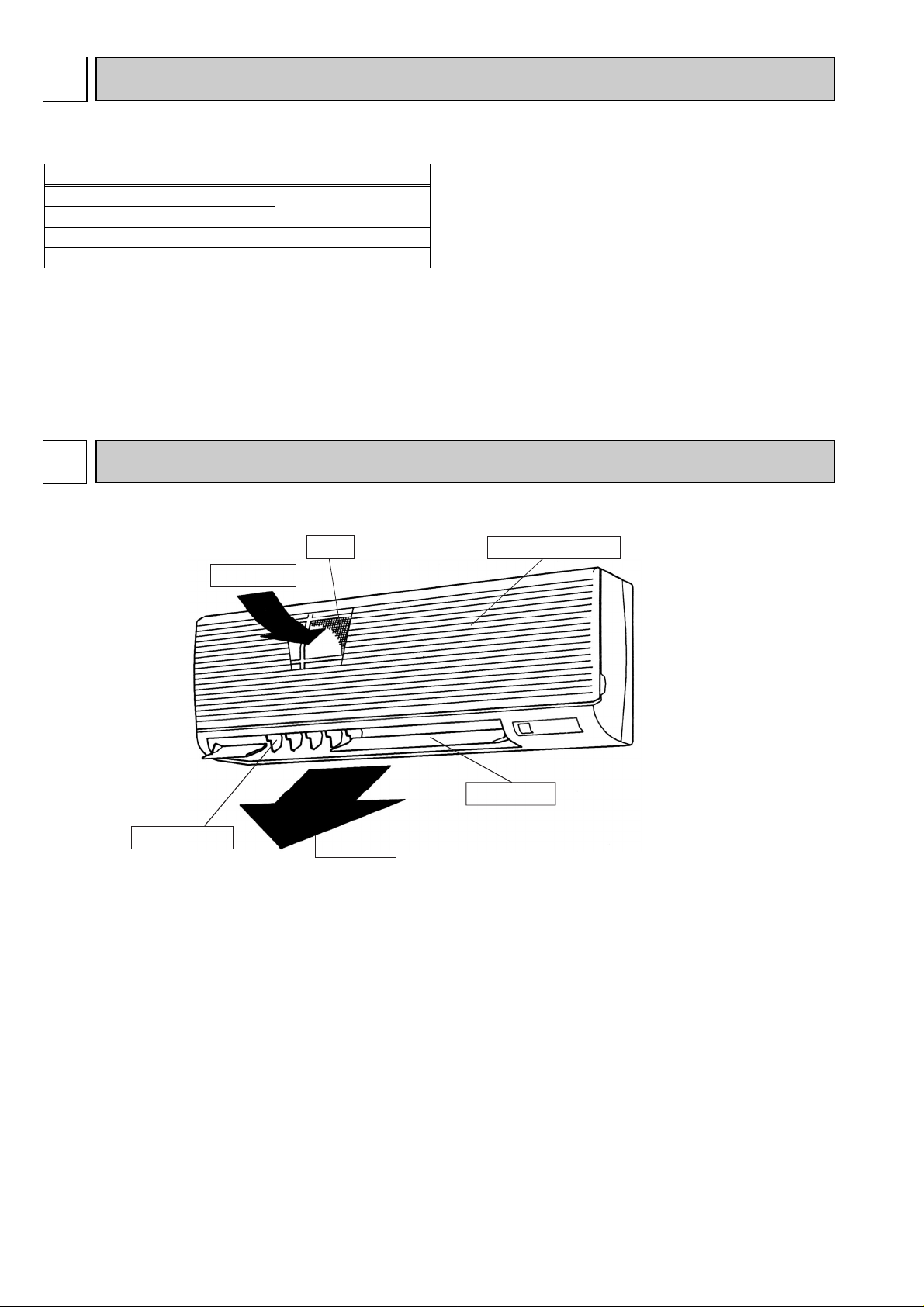
● Indoor Unit
Air intake
Guide vane
Filter
Air outlet
Air intake grille
Auto vane
2
Page 3
ON/OFF TEMP
FAN
VANE
TEST RUN
AUTO STOP
AUTO START
h
min
LOUVER
MODE
CHECK
RESETSET CLOCK
MODEL SELECT
NOT AVAILABLE
CHECK
TEST RUN
˚C
AMPM
AMPM
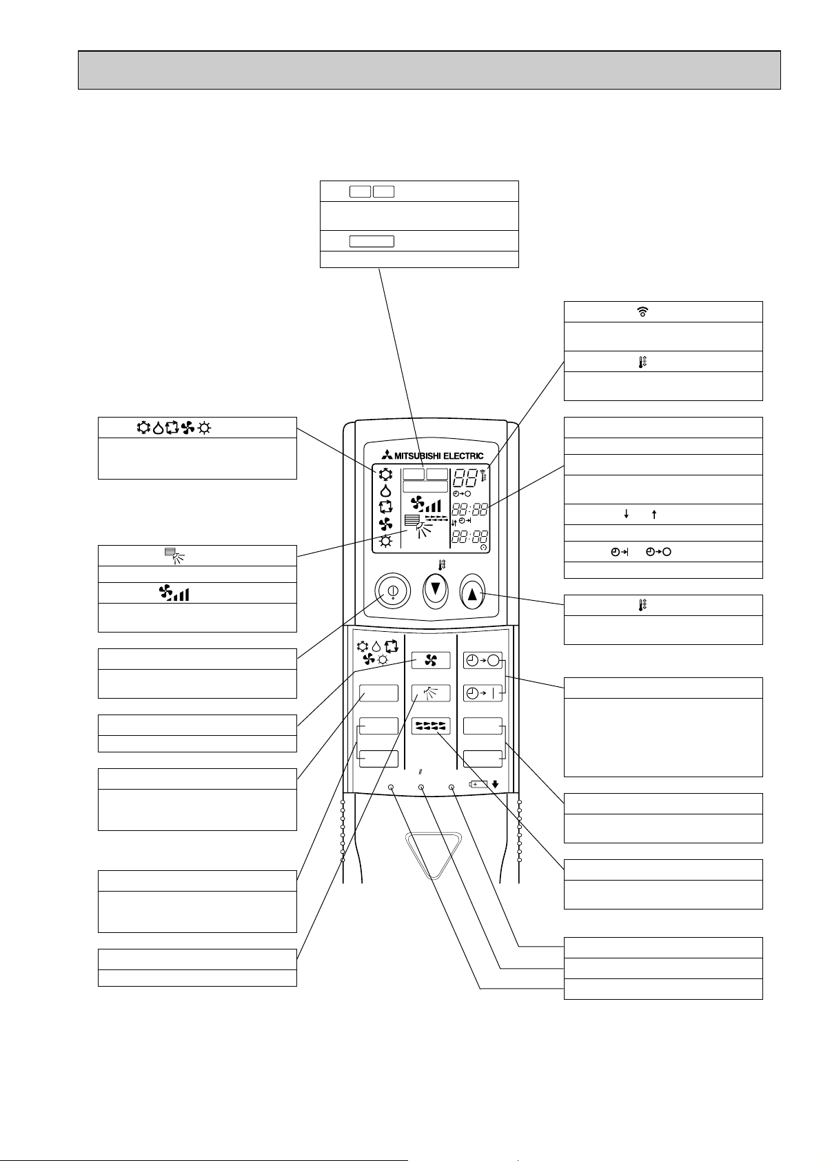
VANE CONTROL button
Used to change the air flow direction.
CLOCK button
RESET button
SET button
ON/OFF button
The unit is turned ON and OFF alternately
each time the button is pressed.
LOUVER button
This switch the horizontal fan motion ON
and OFF.
(Not available for this model.)
MODE SELECT button
Used to switch the operation mode between
cooling, drying, blowing, heating and auto
mode.
CHECK-TEST RUN button
Only press this button to perform an inspection check or test operation.
Do not use it for normal operation.
FAN SPEED SELECT button
Used to change the fan speed.
TIMER display
Displays when in timer operation or when
setting timer.
button
SET TEMPERATURE button sets any desired
room temperature.
CLOCK display
Displays the current time.
“ ” “ ” display
Displays the order of timer operation.
“ ” “ ” display
Displays whether timer is on or off.
w In case the outdoor unit is cool only type,
the heating mode is not available.
Buttons used to set the “hour and minute” of
the current time and timer settings.
h and min buttons
display
SET TEMP. display indicates desired temperature set.
display
FAN SPEED display indicates which fan
speed has been selected.
display
The vertical direction of air flow is indicated.
display
Blinks when model is selected.
display
Lights up while transmission to the indoor
unit is mode using switches.
display
CHECK&TEST RUN display indicates that
the unit is being checked or test-run.
display
OPERATION MODE display
Operation mode display indicates which operation mode is in effect.
TIMER CONTROL buttons
AUTO STOP (OFF timer): when this switch
is set, the air conditioner will be automatically stopped at the preset time.
AUTO START (ON timer): when this switch
is set, the air conditioner will be automatically started at the preset time.
MODEL SELECT
CHECK
TEST RUN
● Wireless remote controller
3
Page 4
Item
Function
Capacity
Total input
Service Ref.
Power supply(phase, cycle, voltage)
Input
Running current
Starting current
External finish
Heat exchanger
Fan Fan(drive) ✕ No.
Fan motor output
Airflow(Low-High)
External static pressure
Booster heater
Operation control & Thermostat
Noise level(Low-High)
Unit drain pipe O.D.
Dimensions
Weight
Service Ref.
Power supply (phase, cycle, voltage)
Input
Running current
Starting current
External finish
Refrigerant control
Compressor
Model
Motor output
Starter type
Protection devices
Heat exchanger
Fan Fan(drive)✕No.
Fan motor output
Airflow
Defrost method
Noise level
Dimensions
Weight
Refrigerant
Charge
Oil<Model>
Pipe size O.D.
Connection method
Between the indoor & outdoor unit
Service Ref.
W
D
H
W
D
H
Liquid A(in.)
Gas A(in.)
Indoor side
Outdoor side
Height difference
Piping length
INDOOR UNITOUTDOOR UNIT
REFRIGERANT PIPING
W
Btu/h
kW
kW
A
A
kW
m
3
/X<CFM>
Pa(mmAq)
kW
>
A(in.)
A(in.)
A(in.)
A(in.)
kg(lbs)
kW
A
A
kW
kW
m
3
/X<CFM>
>
A(in.)
A(in.)
A(in.)
kg(lbs)
kg(lbs)
L
PKH-1.6GAKL
PKH-1.6GAKLH
Cooling
4,500
15,350
1.51
0.07
0.33
0.40
1.44
6.74
Heating
4,650 (5,450)
15,900 (18,600)
1.48 (2.28)
0.07 (0.87)
0.33 (3.66)
0.40 (3.73)
1.41
6.60
PKH-1.6GAKL
PKH-1.6GAKLH
Single, 50Hz, 220-240V
Munsell 0.70Y 8.59/0.97
Plate fin coil
Line flow(direct) ✕ 1
0.030
9-12 (318-424)
0(direct blow)
(0.8)
Remote controller & built-in
36-43
20(13/16)
990 (39)
235 (9-1/4)
340 (13-3/8)
16(35) (17(37))
PUH-1.6VKA.TH
Single, 50Hz, 220-240V
33
Munsell 3.0Y 7.8/1.1
Capillary tube
Hermetic
RH247VFCT
1.2
Line start
Internal thermostat, HP switch
Plate fin coil
Propeller (direct) ✕ 1
0.065
45(1,590)
Reverse cycle
49
870(34-1/4)
295+24(11-5/8 add 1)
650(25-5/8)
53(117)
R-22
2.2(4.9)
0.57<MS-56>
9.52(3/8)
15.88(5/8)
Flared
Flared
Max. 40m
Max. 40m
2.
Guaranteed operating range
Cooling
Heating
Upper limit
Lower limit
Upper limit
Lower limit
Indoor
D.B. 35:, W.B. 22.5:
D.B. 21:, W.B. 15.5:
D.B. 27:
D.B. 20:
Outdoor
D.B. 46:
D.B. -5:
D.B. 21:, W.B. 15.5:
D.B. -8.5:, W.B. -9.5:
3
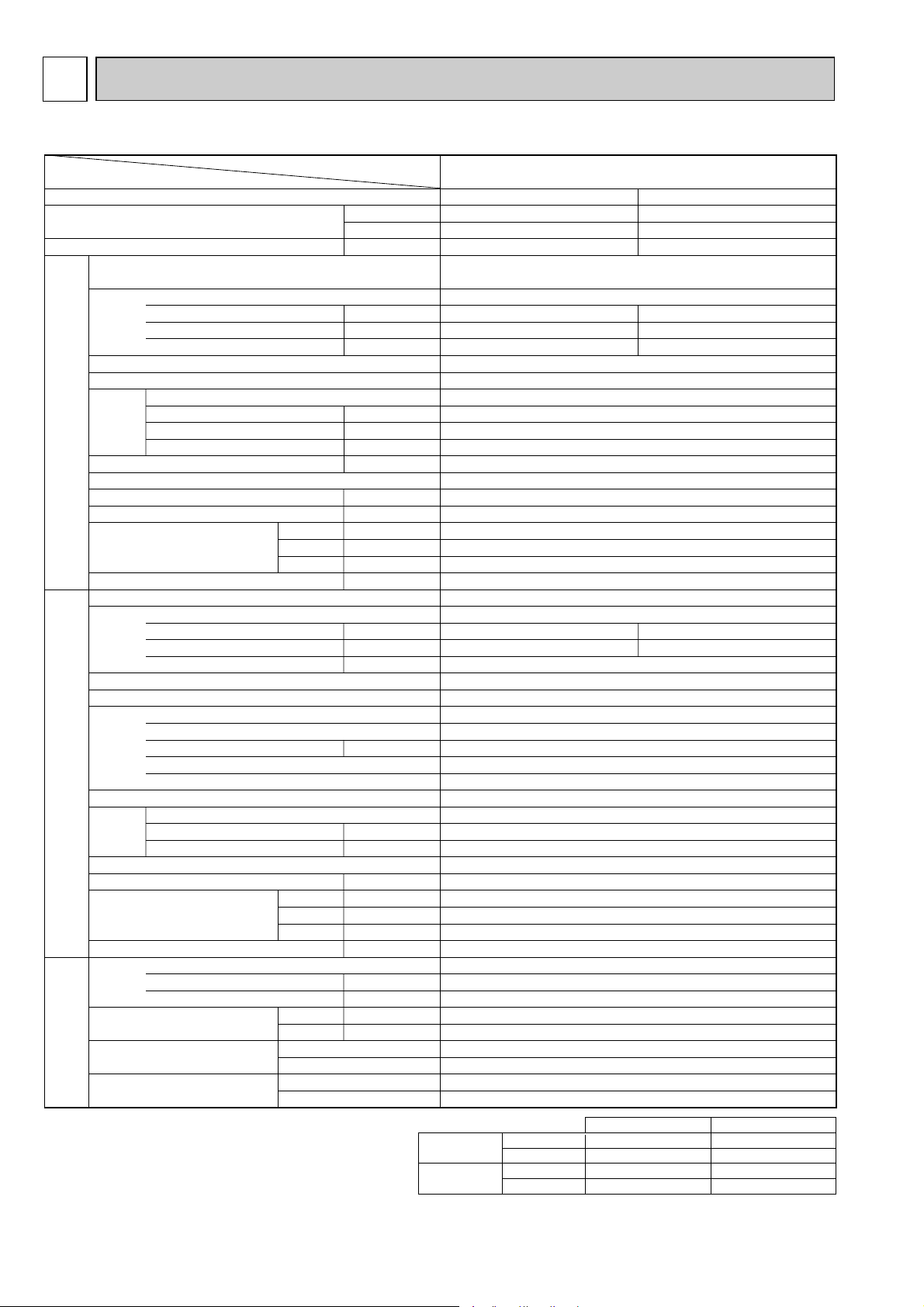
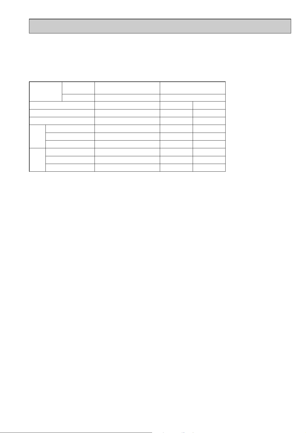
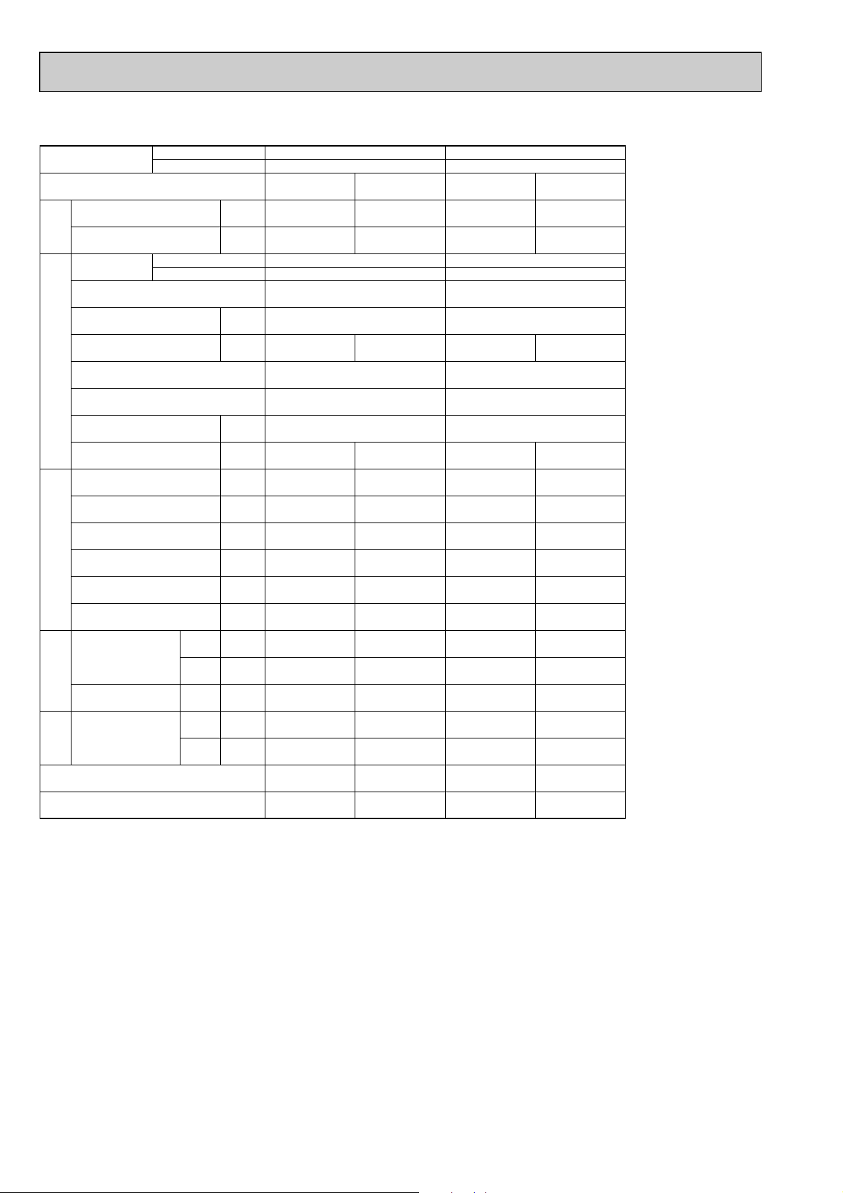
SPECIFICATIONS
STANDARD SPECIFICATION
Note1. Rating Conditions (JIS B 8616)
Cooling : Indoor : D.B. 27°C (80°F), W.B. 19°C (66°F)
Outdoor : D.B. 35°C (95°F), W.B. 24°C (75°F)
Heating : Indoor : D.B. 20°C (68°F)
Outdoor : D.B. 7°C (45°F), W.B. 6°C (43°F)
4
Page 5
Item
Function
Capacity
Total input
Service Ref.
Power supply(phase, cycle, voltage)
Input
Running current
Starting current
External finish
Heat exchanger
Fan Fan(drive) ✕ No.
Fan motor output
Airflow(Low-High)
External static pressure
INDOOR UNITOUTDOOR UNIT
Booster heater
Operation control & Thermostat
Noise level(Low-High)
Unit drain pipe O.D.
Dimensions
Weight
Service Ref.
Power supply (phase, cycle, voltage)
Input
Running current
Starting current
External finish
Refrigerant control
Compressor
Model
Motor output
Starter type
Protection devices
Heat exchanger
Fan Fan(drive)✕No.
Fan motor output
Airflow
Defrost method
Crankcase heater
Noise level
Dimensions
Weight
Refrigerant
Charge
Oil<Model>
Pipe size O.D.
Connection method
Between the indoor & outdoor unit
REFRIGERANT PIPING
Note1. Rating Conditions (JIS B 8616)
Cooling : Indoor : D.B. 27°C (80°F), W.B. 19°C (66°F)
Heating : Indoor : D.B. 20°C (68°F)
Outdoor : D.B. 35°C (95°F), W.B. 24°C (75°F)
Outdoor : D.B. 7°C (45°F), W.B. 6°C (43°F)
Liquid A(in.)
Gas A(in.)
Indoor side
Outdoor side
Height difference
Piping length
W
W
Service Ref.
W
Btu/h
kW
Cooling
5,500
18,800
2.27
PKH-2GAKL
PKH-2GAKLH
Heating
6,250 (7,050)
21,300 (24,100)
2.29 (3.09)
PKH-2GAKL
PKH-2GAKLH
Single, 50Hz, 220-240V
kW
A
A
0.07
0.33
0.40
0.07 (0.87)
0.33 (3.66)
0.40 (3.73)
Munsell 0.70Y 8.59/0.97
Plate fin coil
Line flow(direct) ✕ 1
kW
3
/X<CFM>
m
Pa(mmAq)
kW
Remote controller & built-in
>
A(in.)
A(in.)
D
H
A(in.)
A(in.)
kg(lbs)
0.030
9-12 (318-424)
0(direct blow)
(0.8)
36-43
20(13/16)
990 (39)
235 (9-1/4)
340 (13-3/8)
16(35) (17(37))
PUH-2VKA.TH
Single, 50Hz, 220-240V
kW
A
A
2.20
9.86
45
2.22
9.95
Munsell 3.0Y 7.8/ 1.1
Capillary tube
Hermetic
NH38VMDT
kW
1.7
Line start
Internal thermostat, HP switch
Plate fin coil
Propeller (direct) ✕ 1
kW
3
/X<CFM>
m
W
>
A(in.)
D
H
A(in.)
A(in.)
295+24(11-5/8 add 1)
kg(lbs)
0.065
45(1,590)
Reverse cycle
38
49
870(34-1/4)
650(25-5/8)
64(141)
R-22
kg(lbs)
L
2.2(4.9)
1.2<MS-32>
9.52(3/8)
15.88(5/8)
Flared
Flared
Max. 40m
Max. 40m
Guaranteed operating range
2.
Cooling
Heating
Upper limit
Lower limit
Upper limit
Lower limit
Indoor
D.B. 35:, W.B. 22.5:
D.B. 21:, W.B. 15.5:
D.B. 27:
D.B. 20:
Outdoor
D.B. 46:
D.B. -5:
D.B. 21:, W.B. 15.5:
D.B. -8.5:, W.B. -9.5:
5
Page 6
Item
Function
Capacity
Total input
Service Ref.
Power supply(phase,cycle,voltage)
Input
Running current
Starting current
External finish
Heat exchanger
Fan Fan(drive) ✕ No.
Fan motor output
Airflow(Low-High)
External static pressure
Booster heater
Operation control & Thermostat
Noise level(Low-High)
Unit drain pipe O.D.
Dimensions
Weight
Service Ref.
Power supply (phase, cycle, voltage)
Input
Running current
Starting current
External finish
Refrigerant control
Compressor
Model
Motor output
Starter type
Protection devices
Heat exchanger
Fan Fan(drive)✕No.
Fan motor output
Airflow
Defrost method
Crankcase heater
Noise level
Dimensions
Weight
Refrigerant
Charge
Oil<Model>
Pipe size O.D.
Connection method
Between the indoor & outdoor unit
Service Ref.
W
D
H
W
D
H
Liquid A(in.)
Gas A(in.)
Indoor side
Outdoor side
Height difference
Piping length
INDOOR UNITOUTDOOR UNIT
REFRIGERANT PIPING
W
Btu/h
kW
kW
A
A
kW
m
3
/X<CFM>
Pa(mmAq)
kW
>
A(in.)
A(in.)
A(in.)
A(in.)
kg(lbs)
kW
A
A
kW
kW
m
3
/X<CFM>
W
>
A(in.)
A(in.)
A(in.)
kg(lbs)
kg(lbs)
L
PKH-2GAKL
Cooling
5,400
18,400
2.25
0.07
0.33
0.40
2.18
9.77
Heating
6,100
20,800
2.26
0.07
0.33
0.40
2.19
9.81
PKH-2GAKL
Single, 50Hz, 240V
Munsell 0.70Y 8.59/0.97
Plate fin coil
Line flow(direct) ✕ 1
0.030
9-12 (318-424)
0(direct blow)
-
Remote controller & built-in
36-43
20(13/16)
990 (39)
235 (9-1/4)
340 (13-3/8)
16(35)
PUH-2AKA
1.TH-A
Single, 50Hz, 240V
45
Munsell 3.0Y 7.8/ 1.1
Capillary tube
Hermetic
NH38AMDT
1.7
Line start
Internal thermostat,High-pressure switch
Plate fin coil
Propeller (direct) ✕ 1
0.065
45(1,590)
Reverse cycle
38
49
870(34-1/4)
295+24(11-5/8 add 1)
650(25-5/8)
64(141)
R-22
2.7(6.0)
1.2<MS-32>
9.52(3/8)
15.88(5/8)
Flared
Flared
Max. 40m
Max. 40m
Cooling
Heating
Upper limit
Lower limit
Upper limit
Lower limit
Indoor
D.B. 35:, W.B. 22.5:
D.B. 21:, W.B. 15.5:
D.B. 27:
D.B. 20:
Outdoor
D.B. 46:
D.B. -5:
D.B. 21:, W.B. 15.5:
D.B. -8.5:, W.B. -9.5:
2. Guaranteed operating range
Note1. Rating Conditions (JIS B 8616)
Cooling : Indoor : D.B. 27°C (80°F), W.B. 19°C (66°F)
Outdoor : D.B. 35°C (95°F), W.B. 24°C (75°F)
Heating : Indoor : D.B. 20°C (68°F)
Outdoor : D.B. 7°C (45°F), W.B. 6°C (43°F)
6
Page 7
Item
Function
Capacity
Total input
Service Ref.
Power supply(phase,cycle,voltage)
Input
Running current
Starting current
External finish
Heat exchanger
Fan Fan(drive) ✕ No.
Fan motor output
Airflow(Low-High)
External static pressure
Booster heater
INDOOR UNITOUTDOOR UNIT
Operation control & Thermostat
Noise level(Low-High)
Unit drain pipe O.D.
Dimensions
Weight
Service Ref.
Power supply (phase, cycle, voltage)
Input
Running current
Starting current
External finish
Refrigerant control
Compressor
Model
Motor output
Starter type
Protection devices
Heat exchanger
Fan Fan(drive)✕No.
Fan motor output
Airflow
Defrost method
Crankcase heater
Noise level
Dimensions
Weight
Refrigerant
Charge
Oil<Model>
Pipe size O.D.
Connection method
Between the indoor & outdoor unit
REFRIGERANT PIPING
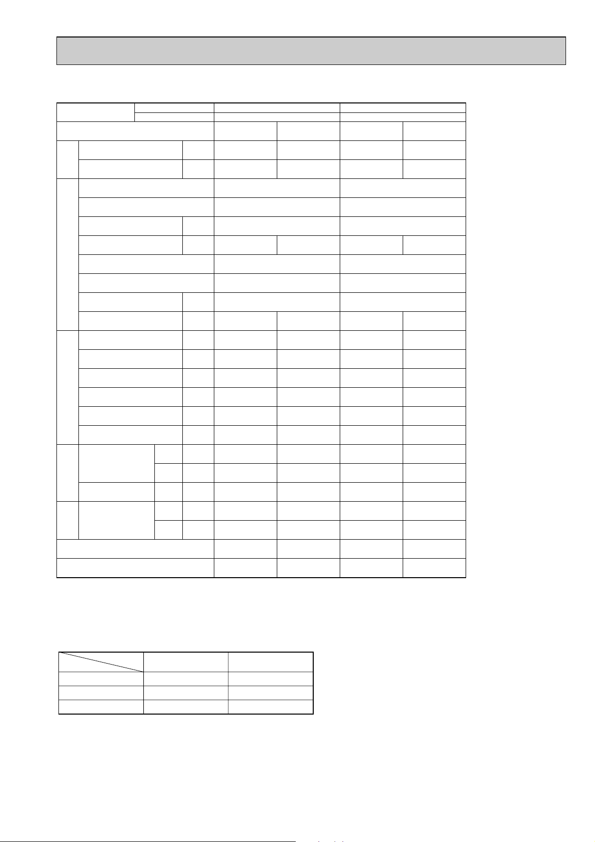
Note1.✴1.Rating Conditions (JIS B 8616)
Cooling : Indoor : D.B. 27°C (80°F), W.B. 19°C (66°F)
✴2.Rating Conditions (SSA385)
Cooling : Indoor : D.B. 29°C , W.B. 19°C
Heating : Indoor : D.B. 21°C
Outdoor : D.B. 35°C (95°F), W.B. 24°C (75°F)
Outdoor : D.B. 46°C
Outdoor : D.B. 7°C , W.B. 6°C
Service Ref.
W
Btu/h
kW
kW
A
A
kW
3
/X<CFM>
m
Pa(mmAq)
kW
>
A(in.)
W
D
H
A(in.)
A(in.)
A(in.)
kg(lbs)
kW
A
A
kW
kW
3
/X<CFM>
m
W
>
W
D
H
A(in.)
A(in.)
A(in.)
kg(lbs)
kg(lbs)
L
Liquid A(in.)
Gas A(in.)
Indoor side
Outdoor side
Height difference
Piping length
Cooling✴1/✴2
5,800/4,800
19,800/16,400
2.48/2.90
0.07
0.33
0.40
Remote controller & built-in
2.41/2.83
11.07/12.99
Internal thermostat,High-pressure switch
2. Guaranteed operating range
Cooling
Heating
Upper limit
Lower limit
Upper limit
Lower limit
PKH-2GAKL
PKH-2GAKL
Single, 60Hz, 220V
Munsell 0.70Y 8.59/0.97
Plate fin coil
Line flow(direct) ✕ 1
0.030
9-12 (318-424)
0(direct blow)
-
36-43
20(13/16)
990 (39)
235 (9-1/4)
340 (13-3/8)
16(35)
PUH-2NKA.TH
Single, 60Hz, 220V
45
Munsell 3.0Y 7.8/ 1.1
Capillary tube
Hermetic
NHJ33NBDT
1.5
Line start
Plate fin coil
Propeller (direct) ✕ 1
0.065
45(1,590)
Reverse cycle
38
49
870(34-1/4)
295+24(11-5/8 add 1)
650(25-5/8)
66.5(147)
R-22
2.2(4.9)
1.2<MS-32>
9.52(3/8)
15.88(5/8)
Flared
Flared
Max. 40m
Max. 40m
Indoor
D.B. 35:, W.B. 22.5:
D.B. 21:, W.B. 15.5:
D.B. 27:
D.B. 20:
Heating✴2
6,250
21,300
2.52
0.07
0.33
0.40
2.45
11.2
Outdoor
D.B. 52:
D.B. -5:
D.B. 21:, W.B. 15.5:
D.B. -8.5:, W.B. -9.5:
7
Page 8
4 DATA
Outdoor intake air D.B.(°C)
20 25 30
Indoor
Intake air
D.B.(°C)
Indoor
Intake air
W.B.(°C)
20
20
20
22
22
22
24
24
24
24
26
26
26
26
27
27
27
27
28
28
28
28
30
30
30
30
32
32
32
32
16
18
20
16
18
20
16
18
20
22
16
18
20
22
16
18
20
22
16
18
20
22
16
18
20
22
16
18
20
22
CA
4540
4834
5131
4540
4834
5131
4540
4834
5131
5431
4540
4834
5131
5431
4540
4834
5131
5431
4540
4834
5131
5431
4540
4834
5131
5431
4540
4834
5131
5431
SHC(W)
2996
2610
2155
3359
2997
2565
3723
3384
2976
2498
4086
3770
3386
2933
4267
3964
3592
3150
4449
4157
3797
3367
4540
4544
4207
3802
4540
4834
4618
4236
SHF
0.66
0.54
0.42
0.74
0.62
0.50
0.82
0.70
0.58
0.46
0.90
0.78
0.66
0.54
0.94
0.82
0.70
0.58
0.98
0.86
0.74
0.62
1.00
0.94
0.82
0.70
1.00
1.00
0.90
0.78
P.C.
1.21
1.23
1.26
1.21
1.23
1.26
1.21
1.23
1.26
1.28
1.21
1.23
1.26
1.28
1.21
1.23
1.26
1.28
1.21
1.23
1.26
1.28
1.21
1.23
1.26
1.28
1.21
1.23
1.26
1.28
CA
4415
4706
5010
4415
4706
5010
4415
4706
5010
5327
4415
4706
5010
5327
4415
4706
5010
5327
4415
4706
5010
5327
4415
4706
5010
5327
4415
4706
5010
5327
SHC(W)
2914
2541
2104
3267
2918
2505
3621
3294
2906
2450
3974
3671
3307
2877
4151
3859
3507
3090
4327
4047
3708
3303
4415
4424
4108
3729
4415
4706
4509
4155
SHF
0.66
0.54
0.42
0.74
0.62
0.50
0.82
0.70
0.58
0.46
0.90
0.78
0.66
0.54
0.94
0.82
0.70
0.58
0.98
0.86
0.74
0.62
1.00
0.94
0.82
0.70
1.00
1.00
0.90
0.78
P.C.
1.26
1.29
1.31
1.26
1.29
1.31
1.26
1.29
1.31
1.34
1.26
1.29
1.31
1.34
1.26
1.29
1.31
1.34
1.26
1.29
1.31
1.34
1.26
1.29
1.31
1.34
1.26
1.29
1.31
1.34
CA
4253
4535
4831
4253
4535
4831
4253
4535
4831
5142
4253
4535
4831
5142
4253
4535
4831
5142
4253
4535
4831
5142
4253
4535
4831
5142
4253
4535
4831
5142
SHC(W)
2807
2449
2029
3147
2812
2416
3488
3174
2802
2365
3828
3537
3189
2777
3998
3719
3382
2983
4168
3900
3575
3188
4253
4263
3962
3600
4253
4535
4348
4011
SHF
0.66
0.54
0.42
0.74
0.62
0.50
0.82
0.70
0.58
0.46
0.90
0.78
0.66
0.54
0.94
0.82
0.70
0.58
0.98
0.86
0.74
0.62
1.00
0.94
0.82
0.70
1.00
1.00
0.90
0.78
P.C.
1.36
1.39
1.42
1.36
1.39
1.42
1.36
1.39
1.42
1.45
1.36
1.39
1.42
1.45
1.36
1.39
1.42
1.45
1.36
1.39
1.42
1.45
1.36
1.39
1.42
1.45
1.36
1.39
1.42
1.45
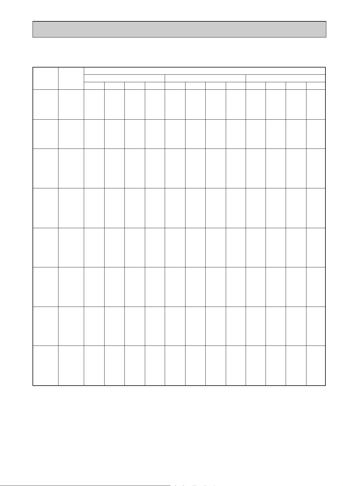
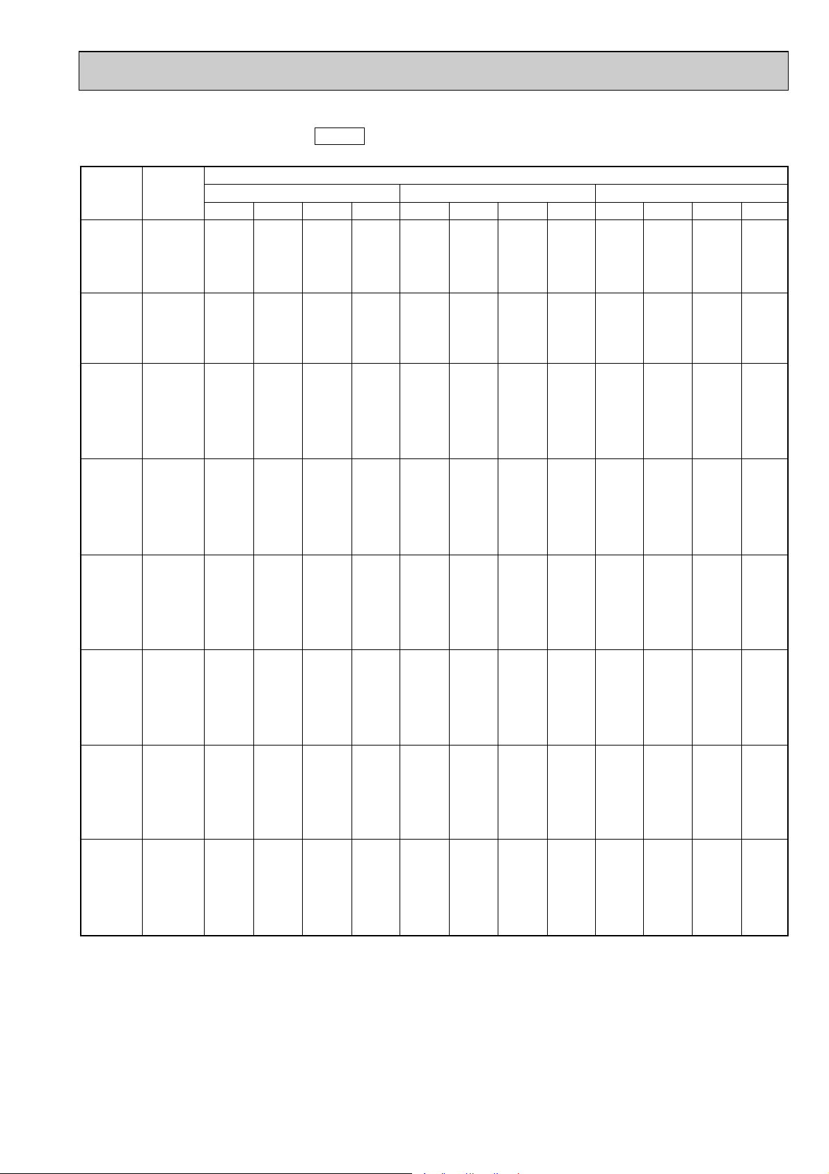
4-1. PERFORMANCE DATA
1) COOLING CAPACITY<1>
PKH-1.6GAKL
PKH-1.6GAKLH
CA : Capacity (W) SHC(W) : Sensible heat capacity
P.C. : Power consumption (kW) SHF : Sensible heat factor
8
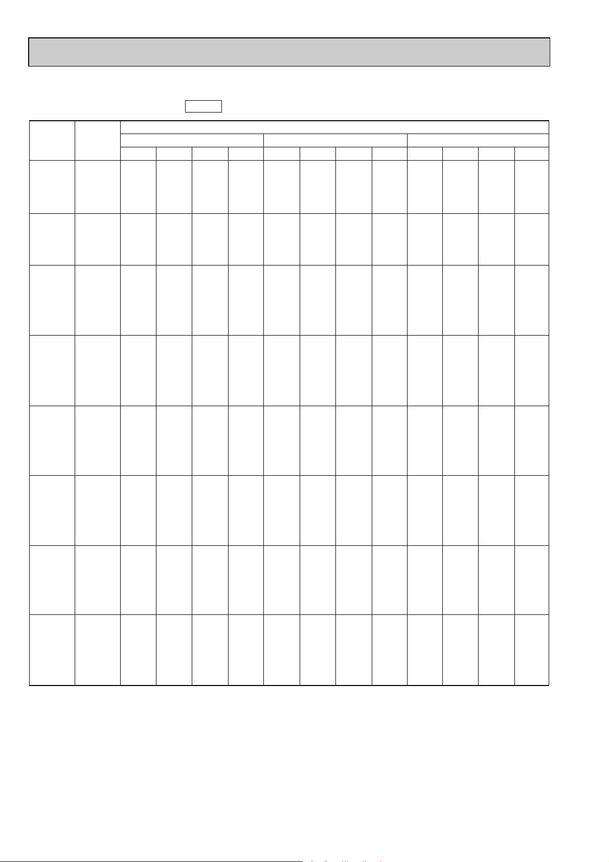
Page 9
COOLING CAPACITY<2>
Outdoor intake air D.B.(°C)
35 40 45
Indoor
Intake air
D.B.(°C)
Indoor
Intake air
W.B.(°C)
20
20
20
22
22
22
24
24
24
24
26
26
26
26
27
27
27
27
28
28
28
28
30
30
30
30
32
32
32
32
16
18
20
16
18
20
16
18
20
22
16
18
20
22
16
18
20
22
16
18
20
22
16
18
20
22
16
18
20
22
CA
4081
4355
4645
4081
4355
4645
4081
4355
4645
4950
4081
4355
4645
4950
4081
4355
4645
4950
4081
4355
4645
4950
4081
4355
4645
4950
4081
4355
4645
4950
SHC(W)
2693
2352
1951
3020
2700
2322
3346
3049
2694
2277
3673
3397
3066
2673
3836
3571
3251
2871
3999
3745
3437
3069
4081
4094
3809
3465
4081
4355
4180
3861
SHF
0.66
0.54
0.42
0.74
0.62
0.50
0.82
0.70
0.58
0.46
0.90
0.78
0.66
0.54
0.94
0.82
0.70
0.58
0.98
0.86
0.74
0.62
1.00
0.94
0.82
0.70
1.00
1.00
0.90
0.78
P.C.
1.46
1.49
1.53
1.46
1.49
1.53
1.46
1.49
1.53
1.56
1.46
1.49
1.53
1.56
1.46
1.49
1.53
1.56
1.46
1.49
1.53
1.56
1.46
1.49
1.53
1.56
1.46
1.49
1.53
1.56
CA
3899
4167
4451
3899
4167
4451
3899
4167
4451
4750
3899
4167
4451
4750
3899
4167
4451
4750
3899
4167
4451
4750
3899
4167
4451
4750
3899
4167
4451
4750
SHC(W)
2573
2250
1869
2885
2583
2225
3197
2917
2581
2185
3509
3250
2937
2565
3665
3417
3116
2755
3821
3583
3294
2945
3899
3917
3650
3325
3899
4167
4006
3705
SHF
0.66
0.54
0.42
0.74
0.62
0.50
0.82
0.70
0.58
0.46
0.90
0.78
0.66
0.54
0.94
0.82
0.70
0.58
0.98
0.86
0.74
0.62
1.00
0.94
0.82
0.70
1.00
1.00
0.90
0.78
P.C.
1.55
1.59
1.64
1.55
1.59
1.64
1.55
1.59
1.64
1.68
1.55
1.59
1.64
1.68
1.55
1.59
1.64
1.68
1.55
1.59
1.64
1.68
1.55
1.59
1.64
1.68
1.55
1.59
1.64
1.68
CA
3706
3970
4249
3706
3970
4249
3706
3970
4249
4543
3706
3970
4249
4543
3706
3970
4249
4543
3706
3970
4249
4543
3706
3970
4249
4543
3706
3970
4249
4543
SHC(W)
2446
2144
1785
2743
2461
2124
3039
2779
2464
2090
3335
3097
2804
2453
3484
3255
2974
2635
3632
3414
3144
2817
3706
3732
3484
3180
3706
3970
3824
3543
SHF
0.66
0.54
0.42
0.74
0.62
0.50
0.82
0.70
0.58
0.46
0.90
0.78
0.66
0.54
0.94
0.82
0.70
0.58
0.98
0.86
0.74
0.62
1.00
0.94
0.82
0.70
1.00
1.00
0.90
0.78
P.C.
1.65
1.70
1.75
1.65
1.70
1.75
1.65
1.70
1.75
1.81
1.65
1.70
1.75
1.81
1.65
1.70
1.75
1.81
1.65
1.70
1.75
1.81
1.65
1.70
1.75
1.81
1.65
1.70
1.75
1.81
PKH-1.6GAKL
PKH-1.6GAKLH
CA : Capacity (W) SHC(W) : Sensible heat capacity
P.C. : Power consumption (kW) SHF : Sensible heat factor
9
Page 10
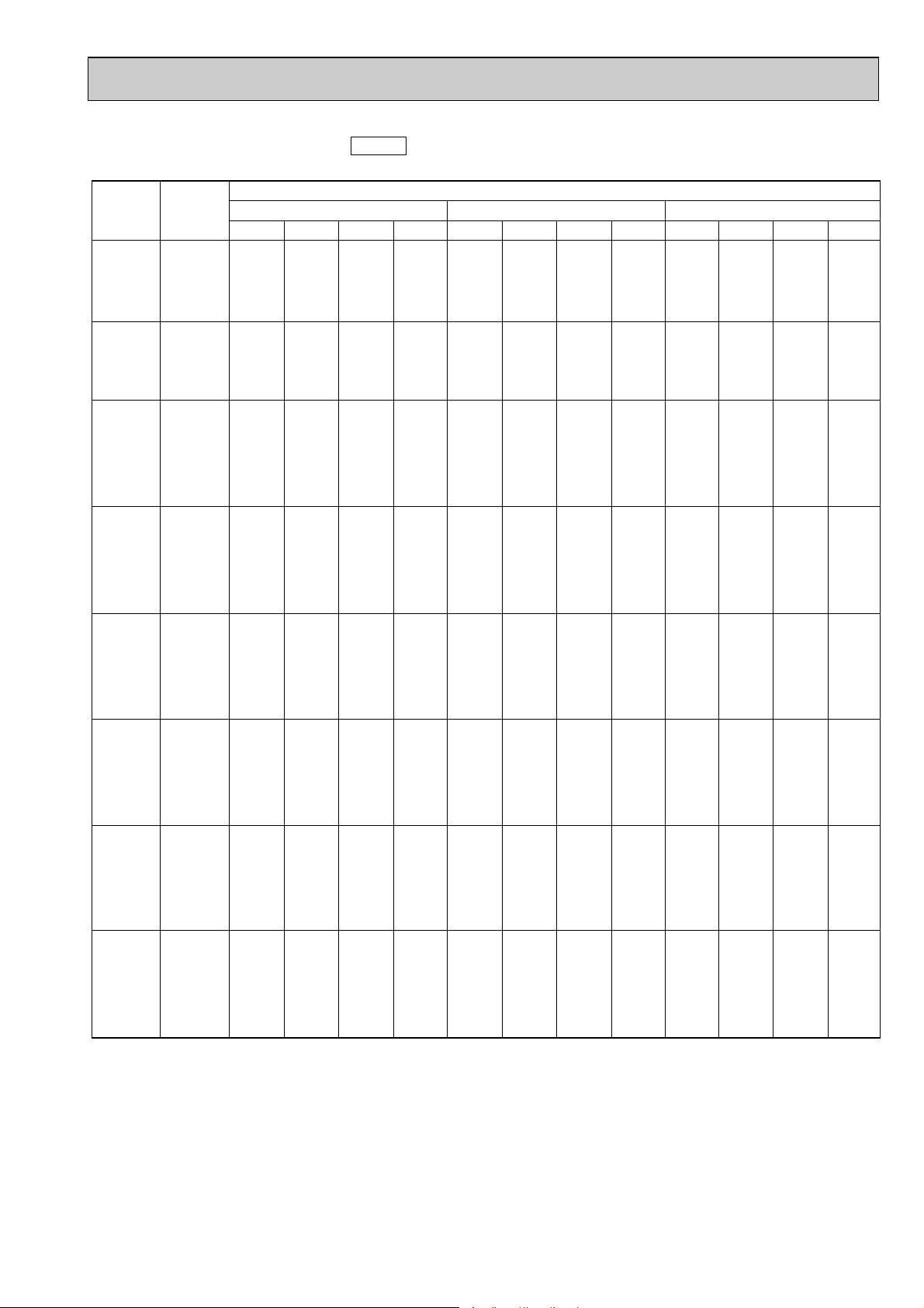
COOLING CAPACITY<3>
Outdoor intake air D.B.(°C)
20 25 30
Indoor
Intake air
D.B.(°C)
Indoor
Intake air
W.B.(°C)
20
20
20
22
22
22
24
24
24
24
26
26
26
26
27
27
27
27
28
28
28
28
30
30
30
30
32
32
32
32
16
18
20
16
18
20
16
18
20
22
16
18
20
22
16
18
20
22
16
18
20
22
16
18
20
22
16
18
20
22
CA
5549
5908
6271
5549
5908
6271
5549
5908
6271
6638
5549
5908
6271
6638
5549
5908
6271
6638
5549
5908
6271
6638
5549
5908
6271
6638
5549
5908
6271
6638
SHC(W)
3274
2777
2195
3718
3249
2696
4161
3722
3198
2589
4605
4195
3700
3120
4827
4431
3951
3385
5049
4667
4202
3651
5493
5140
4703
4182
5549
5612
5205
4713
SHF
0.59
0.47
0.35
0.67
0.55
0.43
0.75
0.63
0.51
0.39
0.83
0.71
0.59
0.47
0.87
0.75
0.63
0.51
0.91
0.79
0.67
0.55
0.99
0.87
0.75
0.63
1.00
0.95
0.83
0.71
SHF
0.59
0.47
0.35
0.67
0.55
0.43
0.75
0.63
0.51
0.39
0.83
0.71
0.59
0.47
0.87
0.75
0.63
0.51
0.91
0.79
0.67
0.55
0.99
0.87
0.75
0.63
1.00
0.95
0.83
0.71
SHF
0.59
0.47
0.35
0.67
0.55
0.43
0.75
0.63
0.51
0.39
0.83
0.71
0.59
0.47
0.87
0.75
0.63
0.51
0.91
0.79
0.67
0.55
0.99
0.87
0.75
0.63
1.00
0.95
0.83
0.71
P.C.
1.82
1.86
1.89
1.82
1.86
1.89
1.82
1.86
1.89
1.93
1.82
1.86
1.89
1.93
1.82
1.86
1.89
1.93
1.82
1.86
1.89
1.93
1.82
1.86
1.89
1.93
1.82
1.86
1.89
1.93
CA
5397
5752
6124
5397
5752
6124
5397
5752
6124
6511
5397
5752
6124
6511
5397
5752
6124
6511
5397
5752
6124
6511
5397
5752
6124
6511
5397
5752
6124
6511
SHC(W)
3184
2704
2143
3616
3164
2633
4048
3624
3123
2539
4479
4084
3613
3060
4695
4314
3858
3320
4911
4544
4103
3581
5343
5004
4593
4102
5397
5465
5083
4623
P.C.
1.90
1.94
1.97
1.90
1.94
1.97
1.90
1.94
1.97
2.01
1.90
1.94
1.97
2.01
1.90
1.94
1.97
2.01
1.90
1.94
1.97
2.01
1.90
1.94
1.97
2.01
1.90
1.94
1.97
2.01
CA
5198
5543
5905
5198
5543
5905
5198
5543
5905
6285
5198
5543
5905
6285
5198
5543
5905
6285
5198
5543
5905
6285
5198
5543
5905
6285
5198
5543
5905
6285
SHC(W)
3067
2605
2067
3483
3049
2539
3899
3492
3012
2451
4315
3935
3484
2954
4523
4157
3720
3205
4731
4379
3956
3457
5146
4822
4429
3960
5198
5266
4901
4462
P.C.
2.04
2.09
2.13
2.04
2.09
2.13
2.04
2.09
2.13
2.18
2.04
2.09
2.13
2.18
2.04
2.09
2.13
2.18
2.04
2.09
2.13
2.18
2.04
2.09
2.13
2.18
2.04
2.09
2.13
2.18
PKH-2GAKL
PKH-2GAKLH
50Hz
(Outdoor unit : PUH-2VKA.TH)
CA : Capacity (W) SHC(W) : Sensible heat capacity
P.C. : Power consumption (kW) SHF : Sensible heat factor
10
Page 11
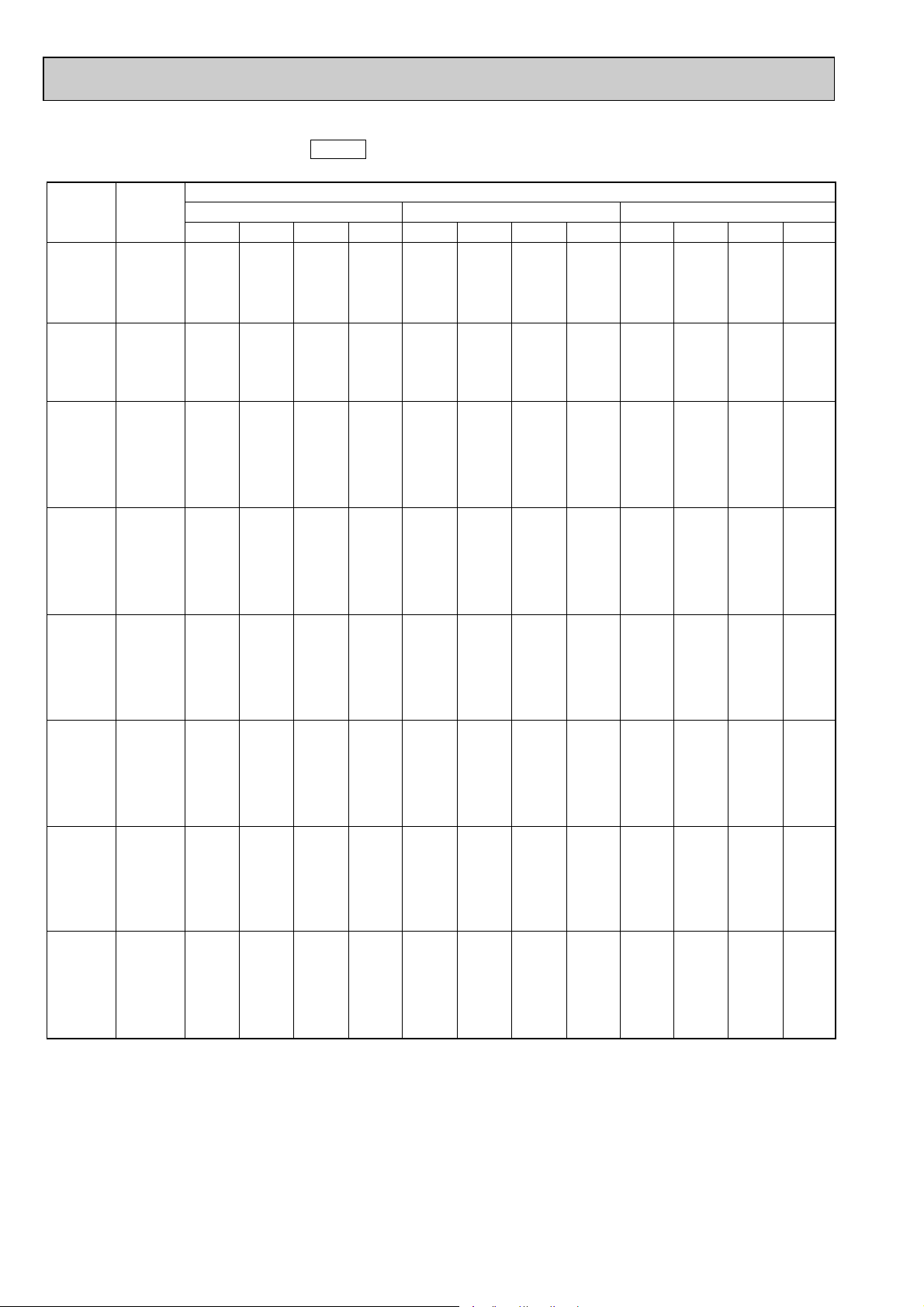
COOLING CAPACITY<4>
Outdoor intake air D.B.(°C)
35 40 45
Indoor
Intake air
D.B.(°C)
Indoor
Intake air
W.B.(°C)
20
20
20
22
22
22
24
24
24
24
26
26
26
26
27
27
27
27
28
28
28
28
30
30
30
30
32
32
32
32
16
18
20
16
18
20
16
18
20
22
16
18
20
22
16
18
20
22
16
18
20
22
16
18
20
22
16
18
20
22
CA
4988
5323
5677
4988
5323
5677
4988
5323
5677
6050
4988
5323
5677
6050
4988
5323
5677
6050
4988
5323
5677
6050
4988
5323
5677
6050
4988
5323
5677
6050
SHC(W)
2943
2502
1987
3342
2928
2411
3741
3353
2895
2360
4140
3779
3349
2844
4339
3992
3577
3086
4539
4205
3804
3328
4938
4631
4258
3812
4988
5057
4712
4296
P.C.
2.19
2.24
2.30
2.19
2.24
2.30
2.19
2.24
2.30
2.35
2.19
2.24
2.30
2.35
2.19
2.24
2.30
2.35
2.19
2.24
2.30
2.35
2.19
2.24
2.30
2.35
2.19
2.24
2.30
2.35
CA
4765
5093
5440
4765
5093
5440
4765
5093
5440
5806
4765
5093
5440
5806
4765
5093
5440
5806
4765
5093
5440
5806
4765
5093
5440
5806
4765
5093
5440
5806
SHC(W)
2811
2394
1904
3192
2801
2339
3574
3208
2774
2264
3955
3616
3209
2729
4145
3820
3427
2961
4336
4023
3645
3193
4717
4431
4080
3658
4765
4838
4515
4122
P.C.
2.34
2.40
2.46
2.34
2.40
2.46
2.34
2.40
2.46
2.53
2.34
2.40
2.46
2.53
2.34
2.40
2.46
2.53
2.34
2.40
2.46
2.53
2.34
2.40
2.46
2.53
2.34
2.40
2.46
2.53
CA
4530
4852
5193
4530
4852
5193
4530
4852
5193
5552
4530
4852
5193
5552
4530
4852
5193
5552
4530
4852
5193
5552
4530
4852
5193
5552
4530
4852
5193
5552
SHC(W)
2673
2281
1818
3035
2669
2233
3397
3057
2648
2165
3760
3445
3064
2610
3941
3639
3272
2832
4122
3833
3479
3054
4484
4221
3895
3498
4530
4610
4310
3942
P.C.
2.49
2.55
2.63
2.49
2.55
2.63
2.49
2.55
2.63
2.71
2.49
2.55
2.63
2.71
2.49
2.55
2.63
2.71
2.49
2.55
2.63
2.71
2.49
2.55
2.63
2.71
2.49
2.55
2.63
2.71
SHF
0.59
0.47
0.35
0.67
0.55
0.43
0.75
0.63
0.51
0.39
0.83
0.71
0.59
0.47
0.87
0.75
0.63
0.51
0.91
0.79
0.67
0.55
0.99
0.87
0.75
0.63
1.00
0.95
0.83
0.71
SHF
0.59
0.47
0.35
0.67
0.55
0.43
0.75
0.63
0.51
0.39
0.83
0.71
0.59
0.47
0.87
0.75
0.63
0.51
0.91
0.79
0.67
0.55
0.99
0.87
0.75
0.63
1.00
0.95
0.83
0.71
SHF
0.59
0.47
0.35
0.67
0.55
0.43
0.75
0.63
0.51
0.39
0.83
0.71
0.59
0.47
0.87
0.75
0.63
0.51
0.91
0.79
0.67
0.55
0.99
0.87
0.75
0.63
1.00
0.95
0.83
0.71
PKH-2GAKL
PKH-2GAKLH
50Hz
(Outdoor unit : PUH-2VKA.TH)
CA : Capacity (W) SHC(W) : Sensible heat capacity
P.C. : Power consumption (kW) SHF : Sensible heat factor
11
Page 12
COOLING CAPACITY<5>
Outdoor intake air D.B.(°C)
20 25 30
Indoor
Intake air
D.B.(°C)
Indoor
Intake air
W.B.(°C)
20
20
20
22
22
22
24
24
24
24
26
26
26
26
27
27
27
27
28
28
28
28
30
30
30
30
32
32
32
32
16
18
20
16
18
20
16
18
20
22
16
18
20
22
16
18
20
22
16
18
20
22
16
18
20
22
16
18
20
22
CA
5448
5800
6157
5448
5800
6157
5448
5800
6157
6517
5448
5800
6157
6517
5448
5800
6157
6517
5448
5800
6157
6517
5448
5800
6157
6517
5448
5800
6157
6517
SHC(W)
3269
2784
2216
3704
3248
2709
4140
3712
3202
2607
4576
4176
3694
3128
4794
4408
3940
3389
5012
4640
4187
3650
5448
5104
4679
4171
5448
5568
5172
4692
SHF
0.60
0.48
0.36
0.68
0.56
0.44
0.76
0.64
0.52
0.40
0.84
0.72
0.60
0.48
0.88
0.76
0.64
0.52
0.92
0.80
0.68
0.56
1.00
0.88
0.76
0.64
1.00
0.96
0.84
0.72
SHF
0.60
0.48
0.36
0.68
0.56
0.44
0.76
0.64
0.52
0.40
0.84
0.72
0.60
0.48
0.88
0.76
0.64
0.52
0.92
0.80
0.68
0.56
1.00
0.88
0.76
0.64
1.00
0.96
0.84
0.72
SHF
0.60
0.48
0.36
0.68
0.56
0.44
0.76
0.64
0.52
0.40
0.84
0.72
0.60
0.48
0.88
0.76
0.64
0.52
0.92
0.80
0.68
0.56
1.00
0.88
0.76
0.64
1.00
0.96
0.84
0.72
P.C.
1.80
1.84
1.87
1.80
1.84
1.87
1.80
1.84
1.87
1.91
1.80
1.84
1.87
1.91
1.80
1.84
1.87
1.91
1.80
1.84
1.87
1.91
1.80
1.84
1.87
1.91
1.80
1.84
1.87
1.91
CA
5299
5648
6012
5299
5648
6012
5299
5648
6012
6392
5299
5648
6012
6392
5299
5648
6012
6392
5299
5648
6012
6392
5299
5648
6012
6392
5299
5648
6012
6392
SHC(W)
3179
2711
2164
3603
3163
2645
4027
3615
3126
2557
4451
4066
3607
3068
4663
4292
3848
3324
4875
4518
4008
3580
5299
4970
4569
4091
5299
5422
5050
4602
P.C.
1.88
1.92
1.96
1.88
1.92
1.96
1.88
1.92
1.96
2.00
1.88
1.92
1.96
2.00
1.88
1.92
1.96
2.00
1.88
1.92
1.96
2.00
1.88
1.92
1.96
2.00
1.88
1.92
1.96
2.00
CA
5104
5442
5798
5104
5442
5798
5104
5442
5798
6171
5104
5442
5798
6171
5104
5442
5798
6171
5104
5442
5798
6171
5104
5442
5798
6171
5104
5442
5798
6171
SHC(W)
3062
2612
2087
3471
3048
2551
3879
3483
3015
2468
4287
3918
3479
2962
4491
4136
3710
3209
4696
4354
3942
3456
5104
4789
4406
3949
5104
5224
4870
4443
P.C.
2.02
2.07
2.12
2.02
2.07
2.12
2.02
2.07
2.12
2.16
2.02
2.07
2.12
2.16
2.02
2.07
2.12
2.16
2.02
2.07
2.12
2.16
2.02
2.07
2.12
2.16
2.02
2.07
2.12
2.16
PKH-2GAKL
50Hz
(Outdoor unit : PUH-2AKA1·TH-A)
CA : Capacity (W) SHC(W) : Sensible heat capacity
P.C. : Power consumption (kW) SHF : Sensible heat factor
12
Page 13
COOLING CAPACITY<6>
Outdoor intake air D.B.(°C)
35 40 45
Indoor
Intake air
D.B.(°C)
Indoor
Intake air
W.B.(°C)
20
20
20
22
22
22
24
24
24
24
26
26
26
26
27
27
27
27
28
28
28
28
30
30
30
30
32
32
32
32
16
18
20
16
18
20
16
18
20
22
16
18
20
22
16
18
20
22
16
18
20
22
16
18
20
22
16
18
20
22
CA
4897
5226
5574
4897
5226
5574
4897
5226
5574
5940
4897
5226
5574
5940
4897
5226
5574
5940
4897
5226
5574
5940
4897
5226
5574
5940
4897
5226
5574
5940
SHC(W)
2938
2509
2007
3330
2927
2452
3772
3345
2898
2376
4114
3763
3344
2851
4309
3972
3567
3089
4505
4181
3790
3327
4897
4599
4236
3802
4897
5017
4682
4277
P.C.
2.17
2.22
2.28
2.17
2.22
2.28
2.17
2.22
2.28
2.33
2.17
2.22
2.28
2.33
2.17
2.22
2.28
2.33
2.17
2.22
2.28
2.33
2.17
2.22
2.28
2.33
2.17
2.22
2.28
2.33
CA
4678
5000
5341
4678
5000
5341
4678
5000
5341
5700
4678
5000
5341
5700
4678
5000
5341
5700
4678
5000
5341
5700
4678
5000
5341
5700
4678
5000
5341
5700
SHC(W)
2807
2400
1923
3181
2800
2350
3555
3200
2777
2280
3930
3600
3205
2736
4117
3800
3418
2964
4304
4000
3632
3192
4678
4400
4059
3648
4678
4800
4486
4104
P.C.
2.32
2.38
2.44
2.32
2.38
2.44
2.32
2.38
2.44
2.51
2.32
2.38
2.44
2.51
2.32
2.38
2.44
2.51
2.32
2.38
2.44
2.51
2.32
2.38
2.44
2.51
2.32
2.38
2.44
2.51
CA
4447
4764
5099
4447
4764
5099
4447
4764
5099
5451
4447
4764
5099
5451
4447
4764
5099
5451
4447
4764
5099
5451
4447
4764
5099
5451
4447
4764
5099
5451
SHC(W)
2668
2287
1836
3024
2668
2243
3380
3049
2651
2181
3736
3430
3059
2617
3914
3621
3263
2835
4092
3811
3467
3053
4447
4192
3875
3489
4447
4573
4283
3925
P.C.
2.46
2.53
2.60
2.46
2.53
2.60
2.46
2.53
2.60
2.69
2.46
2.53
2.60
2.69
2.46
2.53
2.60
2.69
2.46
2.53
2.60
2.69
2.46
2.53
2.60
2.69
2.46
2.53
2.60
2.69
SHF
0.60
0.48
0.36
0.68
0.56
0.44
0.76
0.64
0.52
0.40
0.84
0.72
0.60
0.48
0.88
0.76
0.64
0.52
0.92
0.80
0.68
0.56
1.00
0.88
0.76
0.64
1.00
0.96
0.84
0.72
SHF
0.60
0.48
0.36
0.68
0.56
0.44
0.76
0.64
0.52
0.40
0.84
0.72
0.60
0.48
0.88
0.76
0.64
0.52
0.92
0.80
0.68
0.56
1.00
0.88
0.76
0.64
1.00
0.96
0.84
0.72
SHF
0.60
0.48
0.36
0.68
0.56
0.44
0.76
0.64
0.52
0.40
0.84
0.72
0.60
0.48
0.88
0.76
0.64
0.52
0.92
0.80
0.68
0.56
1.00
0.88
0.76
0.64
1.00
0.96
0.84
0.72
PKH-2GAKL
50Hz
(Outdoor unit : PUH-2AKA1·TH-A)
CA : Capacity (W) SHC(W) : Sensible heat capacity
P.C. : Power consumption (kW) SHF : Sensible heat factor
13
Page 14
COOLING CAPACITY<7>
16
18
20
22
CA
5,851
6,230
6,613
7,000
P.C.
1.99
2.03
2.07
2.10
CA
5,691
6,066
6,458
6,866
P.C.
2.07
2.11
2.16
2.20
CA
5,482
5,845
6,227
6,628
P.C.
2.23
2.28
2.33
2.38
CA
5,260
5,613
5,987
6,380
P.C.
2.39
2.45
2.51
2.57
CA
5,025
5,371
5,736
6,123
P.C.
2.55
2.62
2.69
2.76
CA
4,777
5,117
5,476
5,855
P.C.
2.72
2.79
2.87
2.97
20 25 30
Indoor
intake
air
W.B.(˚C)
35
Outdoor intake air D.B.(˚C)
40 45
15
20
25
15
20
25
CA
3,184
3,049
2,930
4,280
4,098
3,939
P.C.
1.01
1.09
1.15
1.56
1.68
1.79
CA
3,650
3,506
3,364
4,905
4,713
4,521
P.C.
1.12
1.20
1.28
1.73
1.86
1.98
CA
4,160
4,003
3,844
5,591
5,380
5,167
P.C.
1.23
1.32
1.42
1.90
2.05
2.19
CA
4,714
4,538
4,370
6,336
6,100
5,874
P.C.
1.35
1.45
1.56
2.09
2.25
2.41
CA
5,312
5,112
4,942
7,139
6,871
6,643
P.C.
1.48
1.59
1.70
2.28
2.46
2.64
CA
5,952
5,724
5,560
8,000
7,693
7,473
P.C.
1.61
1.73
1.86
2.49
2.68
2.87
-10 -5 0Service Ref.
Indoor
intake
air
D.B.(˚C)
PKH-1.6GAKL
PKH-1.6GAKLH
PKH-2GAKL
PKH-2GAKLH
5
Outdoor intake air W.B.(˚C)
10 15
Service Ref.
PKH-1.6GAKL
PKH-1.6GAKLH
PKH-2GAKL
PKH-2GAKLH
Refrigerant piping length(one way)
5m 10m 15m 20m 25m 30m 35m 40m 45m 50m
1.00
1.00
1.00
1.00
1.00
1.00
1.00
1.00
1.00
1.00
1.00
1.00
0.998
0.998
0.995
0.995
—
—
—
—
PKH-2GAKL
CA : Capacity(W)
P.C. : Power consumption (kW)
Cooling capacity correction factors
60Hz
(Outdoor unit : PUH-2NKA.TH)
Service Ref.
PKH-1.6GAKL
PKH-1.6GAKLH
PKH-2GAKL
PKH-2GAKLH
5m 10m 15m 20m 25m 30m 35m 40m 45m 50m
1.00 0.993 0.984
1.00 0.992 0.983
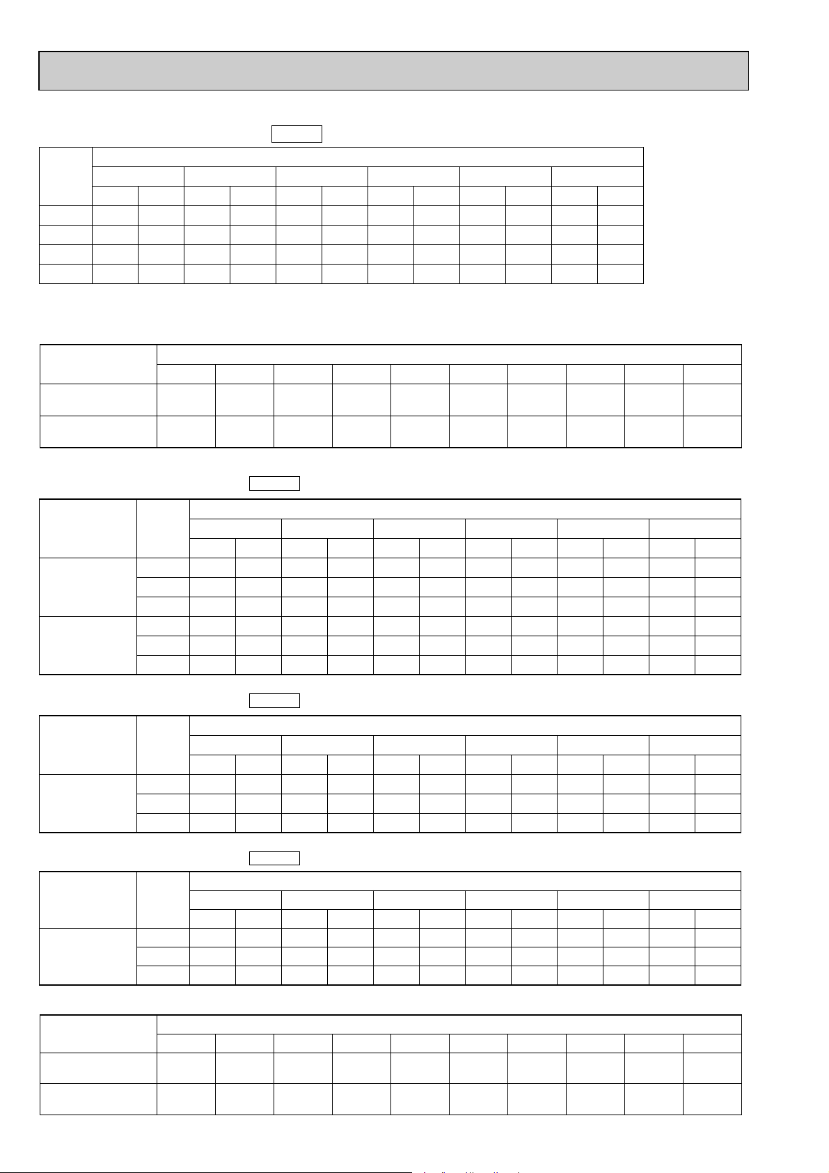
2) HEATING CAPACITY
HEATING CAPACITY
Indoor
intake
air
D.B.(˚C)
15
PKH-2GAKL
20
25
HEATING CAPACITY
Indoor
intake
air
D.B.(˚C)
15
PKH-2GAKL
Heating capacity correction factors
20
25
CA
4,177
4,000
3,844
CA
4,314
4,131
3,970
50Hz
50Hz
(Outdoor unit : PUH-1.6,2VKA.TH)
(Outdoor unit : PUH-2AKA1·TH-A)
-10 -5 0Service Ref.
P.C.
1.54
1.66
1.76
-10 -5 0Service Ref.
P.C.
1.64
1.76
1.87
CA
4,788
4,600
4,413
60Hz
(Outdoor unit : PUH-2NKA.TH)
CA
4,945
4,750
4,558
Refrigerant piping length(one way)
0.978
0.978
0.969
0.966
0.961
0.959
Outdoor intake air W.B.(˚C)
P.C.
1.70
1.84
1.96
P.C.
1.81
1.95
2.08
CA
5,457
5,251
5,043
CA
5,636
5,423
5,208
P.C.
1.88
2.02
2.16
Outdoor intake air W.B.(˚C)
P.C.
1.99
2.15
2.30
CA
6,184
5,953
5,733
CA
6,387
6,149
5,921
14
0.956 0.948
0.950 0.945
CA : Capacity (W)
P.C. : Power consumption (kW)
CA : Capacity (W)
P.C. : Power consumption (kW)
5
P.C.
2.06
2.22
2.38
CA
6,968
6,706
6,483
CA : Capacity (W)
P.C. : Power consumption (kW)
5
P.C.
2.19
2.36
2.52
CA
7,197
6,926
6,696
——
——
10 15
P.C.
2.25
2.43
2.60
10 15
P.C.
2.39
2.58
2.76
CA
7,808
7,509
7,294
CA
8,064
7,755
7,533
P.C.
2.46
2.64
2.84
P.C.
2.61
2.81
3.01
Page 15
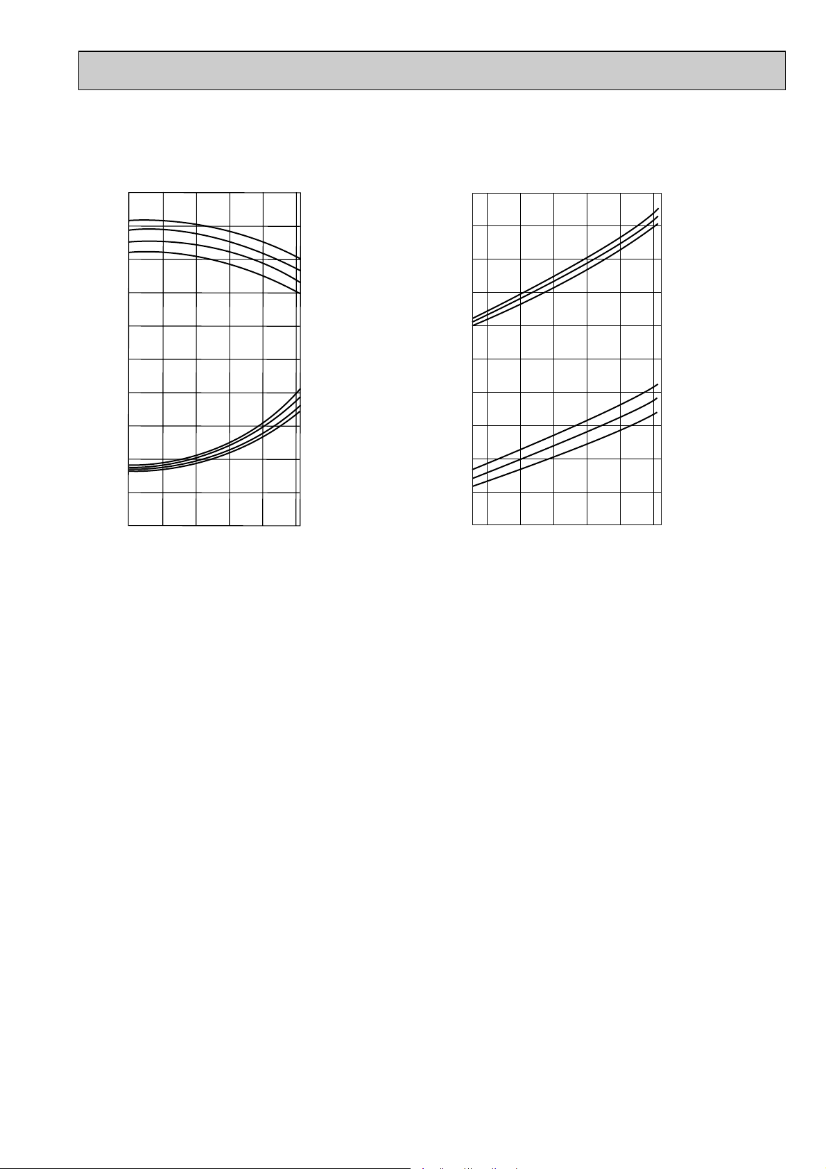
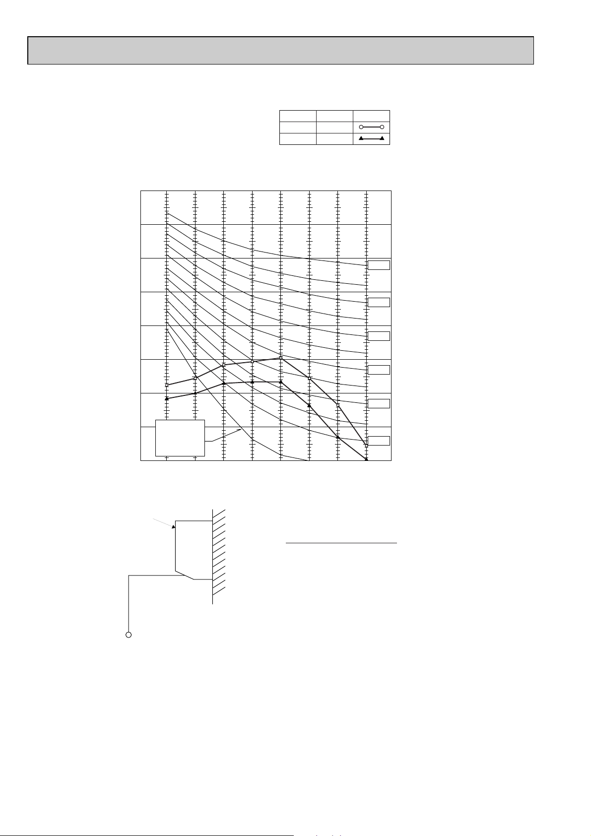
4-2. PERFORMANCE CURVE
1.4
1.2
1.0
0.8
0.6
1.4
1.2
1.0
0.8
0.6
0.4
-5 5 15 253546
OUTDOOR D.B.(°C)
TOTAL INPUT (RATIO) CAPACITY (RATIO)
INDOOR W.B.(°C)
INDOOR W.B.(°C)
22
20
18
16
22
20
18
16
1.4
1.2
1.0
0.8
0.6
1.4
1.2
1.0
0.8
0.6
0.4
-12-10 -5 0 5 10 15
OUTDOOR W.B. (°C)
INDOOR D.B. (°C)
INDOOR D.B. (°C)
15
20
25
25
20
15
TOTAL INPUT (RATIO) CAPACITY (RATIO)
Cooling
Heating
15
Page 16
Service Ref.
Indoor unit
Outdoor unit
PKH-1.6GAKL
PKH-1.6GAKLH
PUH-1.6VKA.TH
Cool
4,450
1.47
0.07
0.33
0.40
1.40
6.76
32
4,600
(5,330)
1.43
(2.16)
0.07
(0.80)
0.33
(3.50)
0.40
(3.57)
Heat
1.36
6.57
32
6,200
(6,930)
2.25
(2.98)
0.07
(0.80)
0.33
(3.50)
0.40
(3.57)
Cool
5,450
2.23
0.07
0.33
0.40
2.16
9.78
44
Heat
2.18
9.87
44
PKH-2GAKL
PKH-2GAKLH
PUH-2VKA.TH
Outdoor
unit
Indoor
unit
Mode
Capacity(W)
Total Input(kW)
Input(kW)
Current(A)
Starting current(A)
Input(kW)
Current(A)
Starting current(A)
Service Ref.
Indoor unit
Outdoor unit
PKH-1.6GAKL
PKH-1.6GAKLH
PUH-1.6VKA.TH
Cool
4,500
1.51
0.07
0.33
0.40
1.44
6.74
33
4,650
(5,450)
1.48
(2.28)
0.07
(0.87)
0.33
(3.66)
0.40
(3.73)
Heat
1.41
6.60
33
6,250
(7,050)
2.29
(3.09)
0.07
(0.87)
0.33
(3.66)
0.40
(3.73)
Cool
5,500
2.27
0.07
0.33
0.40
2.20
9.86
45
Heat
2.22
9.95
45
PKH-2GAKL
PKH-2GAKLH
PUH-2VKA.TH
Outdoor
unit
Indoor
unit
Mode
Capacity(W)
Total Input(kW)
Input(kW)
Current(A)
Starting current(A)
Input(kW)
Current(A)
Starting current(A)
6,100
2.26
0.07
0.33
0.40
Cool
5,400
2.25
0.07
0.33
0.40
2.18
9.77
45
Heat
2.19
9.81
45
PKH-2GAKL
PUH-2AKA
1·TH-A
Service Ref.
Indoor unit
Outdoor unit
PKH-1.6GAKL
PKH-1.6GAKLH
PUH-1.6VKA.TH
Cool
4,400
1.43
0.07
0.33
0.40
1.36
6.79
30
4,550
(5,220)
1.39
(2.06)
0.07
(0.74)
0.33
(3.38)
0.40
(3.45)
Heat
1.32
6.59
30
6,150
(6,820)
2.21
(2.88)
0.07
(0.74)
0.33
(3.38)
0.40
(3.45)
Cool
5,400
2.19
0.07
0.33
0.40
2.12
9.83
43
Heat
2.14
9.93
43
PKH-2GAKL
PKH-2GAKLH
PUH-2VKA.TH
Outdoor
unit
Indoor
unit
Mode
Capacity(W)
Total Input(kW)
Input(kW)
Current(A)
Starting current(A)
Input(kW)
Current(A)
Starting current(A)
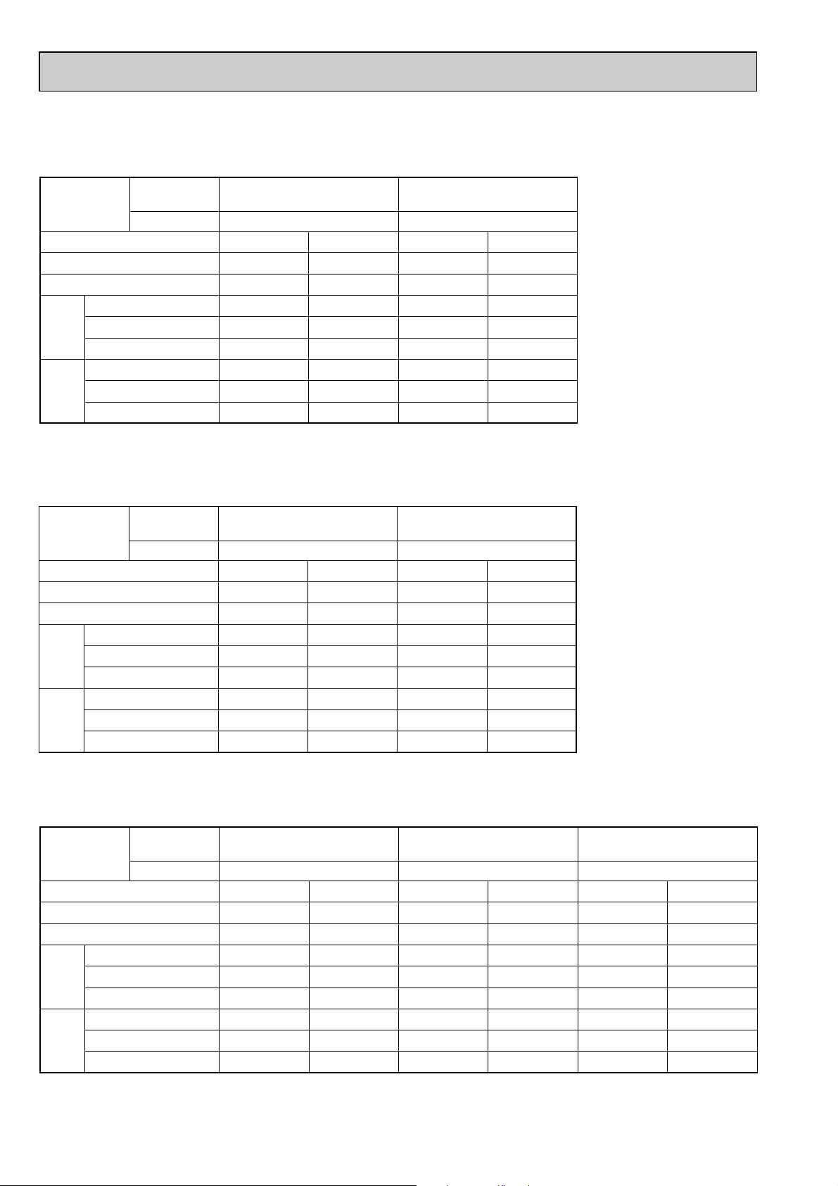
4-3. ELECTRICAL DATA
Indoor unit· · · · · 220V 50Hz 1phase
Outdoor unit · · · 220V 50Hz 1phase
w : ( ) shows the heater on rating.
Indoor unit· · · · · 230V 50Hz 1phase
Outdoor unit· · · · 230V 50Hz 1phase
w : ( ) shows the heater on rating.
Indoor unit· · · · · 240V 50Hz 1phase
Outdoor unit· · · · 240V 50Hz 1phase
w : ( ) shows the heater on rating.
16
Page 17
Indoor unit· · · · · 220V 60Hz 1phase
Outdoor unit· · · · 220V 60Hz 1phase
Rating Conditions ( Cooling)
Indoor : D.B. 27°C , W.B. 19°C
Outdoor : D.B. 35°C
Rating Conditions
(Cooling) : Indoor : D.B. 29°C , W.B. 19°C
Outdoor : D.B. 46°C
(Heating ): Indoor : D.B. 21°C
Outdoor : D.B. 7°C , W.B. 6°C
Service Ref.
Mode
Capacity(W)
Total Input(kW)
Input(kW)
Current(A)
unit
Indoor
Starting current(A)
Input(kW)
Current(A)
unit
Outdoor
Starting current(A)
Indoor unit
Outdoor unit
PKH-2GAKL
PUH-2NKA.TH
Cool
5,800
2.48
0.07
0.33
0.40
2.41
11.07
54
PKH-2GAKL
PUH-2NKA.TH
Cool
4,800
2.90
0.07
0.33
0.40
2.83
12.99
54
Heat
6,250
2.52
0.07
0.33
0.40
2.45
11.2
54
17
Page 18
Outdoor unit Service Ref.
Service Ref.
PKH-1.6GAKL
PKH-1.6GAKLH
Without electric heater
With electric heater
Without electric heater
With electric heater
PKH-1.6GAKL
PKH-1.6GAKLH
PKH-2GAKL
PKH-2GAKLH
PKH-2GAKL
PKH-2GAKLH
CoolingMode
Capacity W
Input
Indoor unit
Service Ref.
Phase, Hz
Volts
Amperes
Phase,Hz
Volts
Amperes
Discharge pressure
Suction pressure
Discharge temperature
Condensing temperature
Suction temperature
Ref.pipe length
Intake air
temperature
Discharge air
temperature
Intake air
temperature
kW
V
A
V
A
4,500
1.51
Heating
4,650
[5,450]
0.33
0.33
[3.66]
0.33
[3.66]
6.74
1.77
(
18.0
)
1.92
(19.6)
2.08
(21.2)
0.46
(
4.7
)
0.37
(3.8)
0.54
(
5.5
)
79
47
8
5
27
19
13.3
35
24
0.76
0.10
6.60
1.85
(18.8)
0.41
(
4.2
)
83
48
0.6
5
20
15
39.2
7
6
-
-
1, 50
240
1, 50
240
PUH-1.6VKA.TH
Cooling Heating
5,500
2.27
6,250
[7,050]
2.29
[3.09]
1.48
[2.28]
0.33
9.86 9.95
87 93
51 54
4–2
55
27 20
19 15
11.7 45.4
35 7
24 6
0.69
-
0.12
-
1, 50
1, 50
240
240
PUH-2VKA.TH
˚C
˚C
˚C
˚C
BF
SHF
˚C
D.B.
D.B.
W.B.
D.B.
W.B.
˚C
˚C
˚C
m
MPa
(
kg/cm
2
)
MPa
(
kg/cm
2
)
Outdoor
side
Indoor side Refrigerant circuit Electrical circuit Total
4-4. STANDARD OPERATION DATA
The unit of pressure has been changed to Mpa on the international system of unit (SI unit system).
The converted score against the traditional unit system can be gotten according to the formula below.
1(Mpa) = 10.2(kg/FF)
18
Page 19
Service Ref.
Air flow m3/
min
Air speed m/
sec
Coverage range m (ft)
PKH-1.6GAKL
PKH-1.6GAKLH
PKH-2GAKL
PKH-2GAKLH
12
5.3
10(32.8)
12
5.3
10(32.8)
Item
Service Ref.
Without electric heater
With electric heater
Mode
PKH-2GAKL
PKH-2GAKLH
Cooling Heating
PKH-2GAKL
PKH-2GAKLH
Cooling Heating
Capacity W
Input
kW
Indoor unit
Service Ref.
Phase,Hz
Volts
Amperes
Outdoor unit Service Ref.
Phase,Hz
Volts
Amperes
Discharge pressure
Suction pressure
Discharge temperature
Condensing temperature
Suction temperature
Ref.pipe length
MPa
(
kg/cm
MPa
(
kg/cm
˚C
˚C
˚C
m
5,400
2.25
PKH-2GAKL
6,100
2.26
5,800
2.48
PKH-2GAKL
1,50
V
A
0.33 0.33
240
PUH-2AKA
1·TH-A
0.33 0.33
PUH-2NKA.TH
1, 50
V
A
9.77 9.81
1.95
2
)
(19.9)
0.47
2
)
(
4.8
240
2.08
(21.2)
0.39
)
(3.8)
92 95
51 54
44
55
11.07 11.20
1.97
(20.1)
0.44
(
)
4.5
70 99
51 55
3–2
55
6,250
2.52
1,60
220
1, 60
220
2.15
(21.9)
0.39
(3.8)
Intake air
temperature
Discharge air
Indoor side Refrigerant circuit Electrical circuit Total
temperature
Intake air
temperature
side
Outdoor
SHF
BF
D.B.
W.B.
D.B.
D.B.
W.B.
˚C
˚C
˚C
˚C
˚C
27 20
19 15
11.9 44
35 7
24 6
0.70
0.12
-
-
27 21
19 15
11.2 46
35 7
24 6
0.68
0.12
-
-
The unit of pressure has been changed to Mpa on the international system of unit (SI unit system).
The converted score against the traditional unit system can be gotten according to the formula below.
1(Mpa) = 10.2(kg/FF)
4-5. OUTLET AIR SPEED AND COVERAGE RANGE
The air coverage range is the value up to the position where the air speed is 0.25m/sec. when air is blown out horizontally from
the unit at the Hi notch position.
The coverage range should be used only as a general guideline since it varies according to the size of the room and the furniture inside the room.
19
Page 20
90
80
70
60
50
40
30
20
10
63 125 250 500 1000 2000 4000 8000
APPROXIMATE
THRESHOLD OF
REARING FOR
CONTINUOUS
NOISE
NC-60
NC-50
NC-40
NC-30
NC-20
NC-70
OCTAVE BAND SOUND PRESSURE LEVEL, dB re 0.002 MICRO BAR
BAND CENTER FREQUENCIES, Hz
PKH-1.6/2GAKL
PKH-1.6/2GAKLH
Hi
NOTCH
Lo
43
SPL(dB)
36
LINE
4-6. NOISE CRITERION CURVES
UNIT
WALL
1m
1m
MICROPHONE
Ambient temperature 27:
20
Page 21
5
BYOFF
ONSTAND
HEATCOOL
OFF BY
ON STAND
COOL HEAT
ÅrÇoÇoÅqÅ@ëOñ Å@ÇeÇqÇnÇmÇs ÅrÇoÇoÅqÅ@ëOñ Å@ÇeÇqÇnÇmÇs
r.SLI
m m
MITSUBISHI ELECTRIC
r.SLI
m m
MITSUBISHI ELECTRIC
21
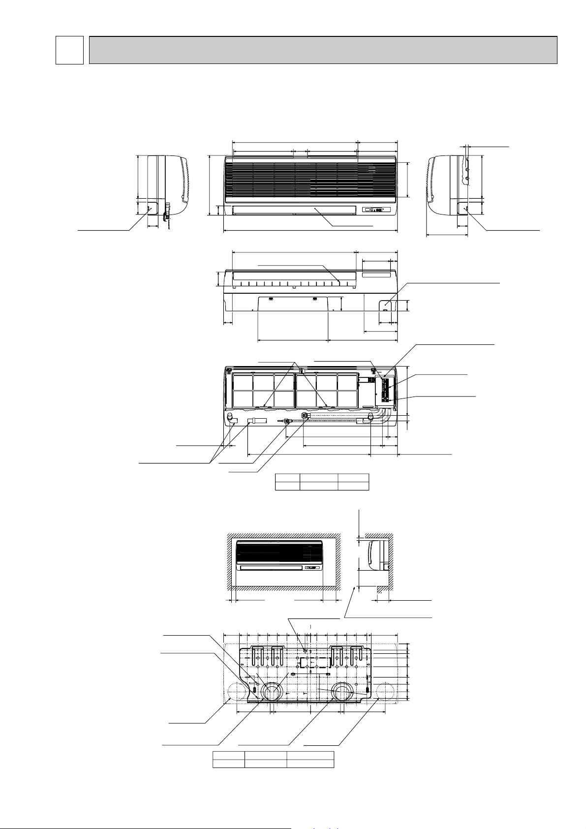
Right side
Less than 15
70
245
60
235
Auto vane
Front view
198 Air intake
53
340
715 Air intake 225
340 Air intake 80 280 Air intake 233
990
21
Left side
Knock out hole
for left piping.
Refrigerant pipe.
Drain pipe.
Wiring hole.
Knock out hole
for left piping.
Refrigerant pipe.
Drain pipe.
Wiring hole.
60
70
245
(Necessary clearance for
Unit installation)
Right side
Allowing clearances
Front view
Less than 130
50 or more 150 or more
180 or more
30 or more
for bolts
Left-rear
piping hole
left-rear piping
R52.5
R52.5
Installation plate
balance point hole
Details of installation plate
49-[5hole
for tapping screw
Knock out hole for
right-rear piping
Right-rear
piping hole
Unit center
14-[14hole
Knock out hole for
425
420
170
190
210
230
0
322
0
35
55
80
130
190
230
272
310
0
3595150
205
260
320
345
495
20
75
135
190
245
300
360
405
495
32
0
w1 Sleeves are available on the market.
w2 This size shows the lower end of through hole.
[90~[100[90
Through holeSleeve w1
1.6 . 2
Model
R52.5
R52.5
Gas pipe
Liquid pipe
Terminal block for
Terminal block to
Terminal block to wired
remote controller
outdoor unit
Filter grip
Service panel
(Power supply access)
5/8F
Gas pipeLiquid pipe
3/8F1.6 . 2
Model
(Right side piping
installation)
(Left side piping
installation)
Unit drain pipe O.D.20
Front view(to open the grille)
700 (Flexible hose total length800)
581
86
449
54
31 280
35
Knock out hole for under piping
Refrigerant piping.Drain pipe.
Wiring hole
12-Louvers(manual)
Lower side
80
50
395400
190
60
70 35
79
160
40
235
705 Air outlet
power supply
153
w2
OUTLINES AND DIMENSIONS
PKH-1.6GAKL PKH-2GAKL
PKH-1.6GAKLH PKH-2GAKLH
Unit : mm
21
Page 22

6 WIRING DIAGRAM
NOTES:
1. Since the outdoor side electric wiring may change be sure to check the outdoor unit electric wiring for servicing.
2. Indoor and outdoor connecting wires are made with polarities, make wiring matching terminal numbers (1, 2, 3).
3. Symbols used in wiring diagram above are, : Connector, : Terminal (block).
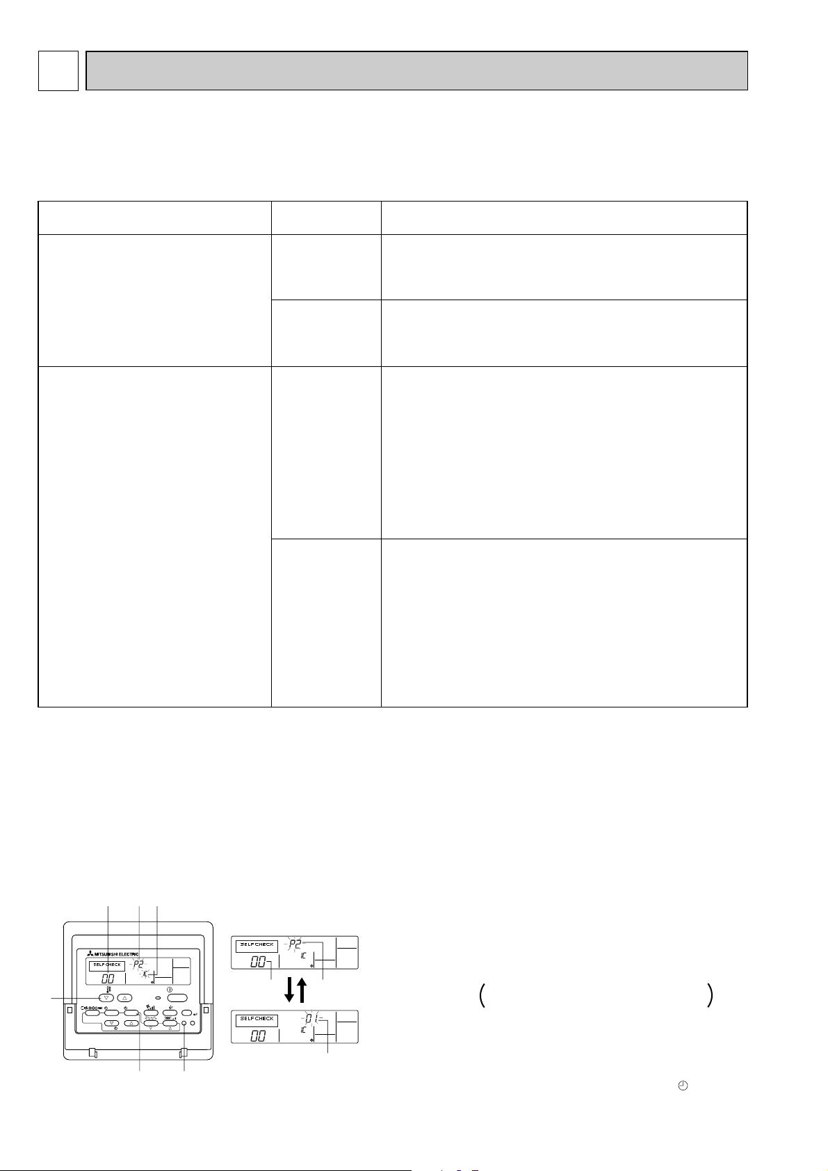
[Self-diagnosis]
Please refer to technical manuals etc.
[Emergency operation procedure]
1.When the indoor unit microcomputer has failed, but all other components work properly, if you set the switch(SWE,SW6)on the
indoor control board, the indoor unit will begin Emergency Operation.
2.When you activate emergency operation of the cooling or heating, you have to set the switch(SWE)and switch(SW6)on indoor
controller.
SWE:ON · Indoor fan is running high speed.
SW6-1:ON · Emergency operation of cooling mode.
SW6-1,2:ON · Emergency operation of heating mode.
3.Before you activate emergency operation, check the following points:
(1) Emergency operation cannot be activated when:
· The outdoor unit malfunctions. · The indoor fan malfunctions.
(2) Emergency operation becomes continuous only by switching the power source on / off. ON / OFF on the remote control or temperature
control etc. does not function.
(3) Avoid operating for a long time when the outdoor unit begins defrosting while emergency operation of the heating is activated,
because it will start to blow cold air.
(4) Emergency cooling should be limited to 10 hours maximum(The indoor unit heat exchanger may freeze).
(5) After emergency operation has been deactivated, set the switches etc. to their original positions.
(6) Movement of the vanes does not work in emergency operation, therefore you have to slowly set them manually to the appropriate
position.
Please set the voltage
using the remote controller.
For the setting method,
please refer to the indoor
unit Installation Manual
SW6
ON
OFF
1 2
WHT
(
WIRERESS
)
CN90
RED
(INTAKE)
CN20
1 2
WHT
(PIPE)
CN21
BLU
(
REMOCON
)
CN22
YLW
(
HEATER
)
CN24
BLK
(
INDOOR/OUTDOOR
COMUNICATION
)
CN30
1 2 1 2
TH1 TH2
6
R.B
(OPTION)
CN41 CN2L
CN51 CN32
W.B
I.B
CNB
RECEIVER
RU
LED1
LED1
LED2
LED2 SW2 SW1
X4
I.B
P.B
CNSK
(RED)
DC13.1V
CN2S
(WHT)
TO OUTDOOR UNIT
POWER SUPPLY
~(1 PHASE)
220-240V 50Hz
220V 60Hz
POWER SUPPLY
~(1 PHASE)
220-240V 50Hz
220V 60Hz
PKH-1.6, 2GAKLH models only
TB4
TB2
1
2
3
L
N
GRN/YLW
ZNR
WHT
(FAN)
FAN
GRN
(VANE)
CN6V
FUSE
ORN
(POWER)
CND
RED
(POWER
BOARD)
CNDK
WHT
(POWER
BOARD)
CN2D
1 3 1 3 1 3
1
1
3
1 2
5
6
2
1 2
3
1
2
5
3 2 1
BLK
WHT WHT
RED
RED
YLW
ORN
BRN
BLU
BLU
RED
BLK
RED
WHT
WHT
GRY
RED
35
61
88H
26H
BLU
RED
FS2FS1H1
WHT
WHT
WHT
YLW
BRN
BLU
MF
MV
BCR
X4
9
1 2 3
2
1
TB5
TRANSMISSION WIRES DC12V
TB6
12
BZ
TB2
L
N
GRN/YLW
88H
SW1
Table 1
1 2 3 4 5
ON
OFF
Table 2
SW2MODELS MODELS
PKH-1.6GAKL(H)
1 2 3 4 5
ON
OFF
PKH-2
GAKL(H)
SW2
1 2 3 4 5
ON
OFF
SW5
Table 3
1 2 3 4 5 6 7 8
ON
OFF
SWE
ON
OFF
SW5SW1 SW2
Refer to tables 1, 2, 3.
[Servicing]
Fasten terminal of the terminal board"TB4"equips lock system.
To remove the fastened terminal, pull it while pressing the protruding
portion (locking lever) of the terminal. The fastened terminal protruding
portion should face upward.
P.B
INDOOR POWER BOARD
SYMBOL NAME
I.B
INDOOR CONTROLLER BOARD
FUSE FUSE (T6.3AL250V)
ZNR VARISTOR
CN2L CONNECTOR<LOSSNAY>
CN32 CONNECTOR<REMOTE SWITCH>
CN41 CONNECTOR<HA TERMINAL-A>
CN51 CONNECTOR<CENTRALLY CONTROL>
SW1 SWITCH <MODEL SELECTION> wSee Table 1.
SW2 SWITCH <CAPACITY CODE> wSee Table 2.
SWE,SW6
SWITCH<EMERGENCY OPERATION>
SW5 SWITCH<SYSTEM SELECTION> wSee Table 3.
X4 RELAY<FAN MOTOR>
BCR
POWER SUPPLY<R.B>
LED1 POWER SUPPLY<I.B>
LED2
FAN CONTROL ELEMENT
C CAPACITOR<FAN MOTOR>
FAN MOTOR
VANE MOTOR
MF
MV
SYMBOL NAME
TB4
TERMINAL BLOCK<INDOOR/OUTDOOR
TB2
TERMINAL BLOCK (POWER SUPPLY)
CONNECTING LINE>
TERMINAL BLOCK<REMOTE CONTROLLER
TRANSMISSION LINE >
TERMINAL BLOCK<REMOTE CONTROLLER
TRANSMISSION LINE >
ROOM TEMP.THERMISTOR
<0:/15k", 25:/5.4k" DETECT>
PIPE TEMP.THERMISTOR/LIQUID
<0:/15k", 25:/5.4k" DETECT>
THERMAL FUSE<104:/10A>
THERMAL FUSE<84:/10A>
HEATER
HEATER THERMAL SWITCH
HEATER CONTACTOR
TB5
TH1
TH2
W.B
R.B
HEATER
WIRELESS REMOTE CONTROLLER BOARD
RECEIVING UNIT
BUZZER
LED<RUN INDICATOR >
LED<HOT ADJUST>
SWITCH<HEATING ON/OFF>
SWITCH<COOLING ON/OFF>
WIRED REMOTE CONTROLLER BOARD
(OPTION)
RU
BZ
LED1
LED2
SW1
SW2
TB6
H1
26H
88H
FS1
FS2
NAMESYMBOL
PKH-1.6GAKL PKH-2GAKL
PKH-1.6GAKLH PKH-2GAKLH
22
Page 23

7
Indoor
heat
exchanger
Indoor unit
Refrigerant pipe
(option)
15.88mm( 5/8")
(with heat insulator)
Refrigerant pipe
(option)
9.52mm( 3/8")
(with heat insulator)
Flexible tube
Flared
connection
Ball valve
Strainer
Ball valve
(with Service port)
Oil separator
4-way valve
Service
port
Service
port
High pressure
control switch
Accumulator
Compressor
Capillary
tube
Strainer
Restrictor
valve
Outdoor heat exchanger
Outdoor coil
thermistor
(TH)
Pipe
temperature
thermistor
(RT2)
PKH-2 (O.D.3.2 I.D.1.8 r500)
O.D.4.0 I.D.2.4 r430
Distributor
with
strainer
Capillary
tube
Capillary
tube
Restrictor
valve
Strainer
Bypass
valve
Muffler
Outdoor unit
O.D.3.2 I.D.1.2 r1250
REFRIGERANT SYSTEM DIAGRAM
PKH-1.6GAKL, PKH-1.6GAKLH / PUH-1.6VKA.TH
PKH-2GAKL, PKH-2GAKLH / PUH-2VKA.TH, PUH-2AKA1.TH-A
Refrigerant flow in cooling
Refrigerant flow in heating
Oil separator
4-way valve
Service
port
Compressor
PUH-1.6 (O.D.3.2 I.D.1.8 L400)
PUH-2 (O.D.4.0 I.D.2.0 L430)
Indoor unit
Indoor
heat
exchanger
Pipe
temperature
thermistor
(RT2)
Distributor
with
strainer
PKH-1.6, 2 (O.D.3.2 I.D.1.8 L500)
Restrictor
valve
Capillary
tube
Strainer
Refrigerant pipe
(option)
15.88mm( 5/8")
(with heat insulator)
Flexible tube
Flared
connection
Refrigerant pipe
(option)
9.52mm( 3/8")
(with heat insulator)
Ball
valve
Strainer
Service
port
Accumulator
Ball valve
(with Service port)
<4-Way valve solenoid coil>
Heating ON
Cooling OFF
High pressure
control switch
Outdoor unit
Outdoor heat exchanger
Bypass
valve
Restrictor
valve
Strainer
Unit : mm
Outdoor coil
thermistor
(TH)
Capillary
tube
PKH-2GAKL / PUH-2NKA.TH
Refrigerant flow in cooling
Refrigerant flow in heating
<R.V. coil>
Heating ON
Cooling OFF
Unit : mm
23
Page 24
8
Unit conditions at service
Error code
Actions to be taken for service (summary)
The inferior phenomenon is
reoccurring.
Displayed
Not displayed
Judge what is wrong and take a corrective action
according to “SELF-DIAGNOSIS ACTION TABLE” (8-3).
Identify the cause of the inferior phenomenon and take
a corrective action according to “TROUBLESHOOTING
BY INFERIOR PHENOMENA ” (8-4).
The inferior phenomenon is
not reoccurring.
Logged
Not logged
1Consider the temporary defects such as the work of
protection devices in the refrigerant circuit including
compressor, poor connection of wiring, noise and etc.
Re-check the symptom, and check the installation
environment, refrigerant amount, weather when the
inferior phenomenon occurred, and wiring related.
2Reset error code logs and restart the unit after finishing
service.
3There is no abnormality in electrical components,
controller boards, and remote controller.
1Recheck the abnormal symptom.
2Identify the cause of the inferior phenomenon and take
a corrective action according to “TROUBLESHOOTING
BY INFERIOR PHENOMENA ” (8-4).
3Continue to operate unit for the time being if the cause
is not ascertained.
4There is no abnormality in electrical components,
controller boards, remote controller etc.
PAR-21MAA
ON/OFF
FILTER
CHECK
OPERATION
CLEAR
TEST
TEMP.
MENU
BACK DAY
MONITOR/SET
CLOCK
ON/OFF
ERROR CODE
ERROR CODE
ERROR CODE
1 Turn on the power.
2 Press the [CHECK] button twice.
3 Set address with [TEMP] button if system control is used.
4 Press the [ON/OFF] button to stop the self-check.
A CHECK button
B Address
C TEMP. button
D IC : Indoor unit
OC: Outdoor unit
E Check code
F Unit No.
G Timer ON/OFF button
A
F
C
BBEED
G
<To delete check code>
1 Display the error code at the self-check result display screen.
2 The address for self-check will blink when the
G ON/OFF
button is pressed twice within three seconds.
– – – – : No trouble generated in the past.
F F F F : No corresponding unit.
TROUBLESHOOTING
8-1. TROUBLESHOOTING
<Error code display by self-diagnosis and actions to be taken for service (summary)>
Present and past error codes are logged and displayed on the wired remote controller or controller board of outdoor unit.
Actions to be taken for service,which depends on whether or not the the inferior phenomenon is reoccurring at service, are
summarized in the table below. Check the contents below before investigating details.
8-2. MALFUNCTION-DIAGNOSIS METHOD BY REMOTE CONTROLLER
<In case of trouble during operation>
When a malfunction occurs to air conditioner, both indoor unit and outdoor unit will stop and operation lamp blinks to inform
unusual stop.
■ Wired remote controller
24
Page 25

<Malfunction-diagnosis method at maintenance service>
ON/OFF
TEMP
FAN
VANE
MODE
CHECK
LOUVER
TEST RUN
AUTO STOP
AUTO START
h
min
RESET
SET
CLOCK
CHECK
CHECK
display
Temperature
button
CHECK
button
Address
display
HOUR
button
ON/OFF
button
[Output pattern A] Errors detected by indoor unit
*1If the beeper does not sound again after the initial
two beeps to confirm the self-check start signal was received and
the OPERATION INDICATOR lamp does not come on,
there are no error records.
*2If the beeper sounds three times continuously “beep, beep, beep (0.4 + 0.4 + 0.4 sec.)” after the initial two beeps to confirm
the self-check start signal was received, the specified refrigerant address is incorrect.
OPERATION
INDICATOR
lamp flash
pattern
Beep
Beep Beep Beep Beep Beep Beep
Off
Approx. 2.5 sec.On0.5 sec.On0.5 sec.On0.5 sec.
On
0.5 sec.
Off
Approx. 2.5 sec.On0.5 sec.On0.5 sec.
· · · Repeated
Number of flashes/beeps in pattern indicates the check
code in the following table (i.e., n=5 for “P5”)
Number of flashes/beeps in pattern indicates
the check code in the following table
n
th
1st2nd3
rd
1st2
nd
Self-check
starts
(Start signal
received)
Beeper sounds
• Refer to the following tables for details on the check codes.
[Output pattern A]
• On wireless remote controller
2The continuous buzzer sounds from receiving section of indoor unit.
3Blink of operation lamp
• On wired remote controller
1Check code displayed in the LCD.
Beeper sounds/OPERATION
INDICATOR lamp flashes 1 Check code
Symptom Remark
(Number of times)
Wireless remote controller
Wired remote controller
1P1
Intake sensor error
2
P2 Pipe (TH2) sensor error
4 P4 Drain sensor error
5
P5
PA
Drain pump error
Forced compressor stop
6 P6 Freezing/ Overheating safeguard operation
8 P8 Pipe temperature error / Outdoor unit error
9 E4, E5 Remote controller signal receiving error
10
–
11
–
–
–
12 Fb Indoor unit control system error (memory error, etc.)
–
E0, E3
– E1, E2 Remote controller control board error
Remote controller transmission error
■ Wireless remote controller
[Procedure]
1. Press the CHECK button twice.
• "CHECK" lights, and address "00" flashes.
• Check that the remote controller's
display has stopped before continuing.
2. Press the temperature
buttons.
3. Point the remote controller at the
sensor on the indoor unit and
press the HOUR button.
4. Point the remote controller at the
sensor on the indoor unit and
press the ON/OFF button.
• Select the address of the indoor unit
for the self-diagnosis.
Main indoor unit : “00”
Sub indoor unit : “01”
• If an air conditioner error occurs, the
indoor unit's sensor emits an intermittent buzzer sound, the operation light
flashes, and the error code is
output.
(It takes 3 seconds at most for error
code to appear.)
• The check mode is cancelled.
25
Page 26

Symptom
Cause
Wired remote controller
On the wireless remote controller with condition above, following phenomena takes place.
• No signals from the remote controller are accepted.
• Operation lamp is blinking.
• The buzzer makes a short piping sound.
PLEASE WAIT
PLEASE WAIT → Error code
Display messages do not
appear even when operation
switch is turned ON (operation
lamp does not light up).
For about 2
minutes following power-on
After about 2
minutes has
expired following power-on
• For about 2 minutes following power-on,operation of the remote controller is not possible
due to system start-up. (Correct operation)
•Connector for the outdoor unit’s protection
device is not connected.
•Reverse or open phase wiring for the outdoor
unit’s power terminal block
•Incorrect wiring between indoor and outdoor
units
•Remote controller wire short
Note:
Operation is not possible for about 30 seconds after cancellation of function selection. (Correct operation)
For description of each LED (LED1, 2) provided on the indoor controller, refer to the following table.
LED1 (power for microcomputer) Indicates whether control power is supplied. Make sure that this LED is
always lit.
LED2 (power for wired remote controller)
Indicates whether power is supplied to the wired remote controller.
This LED lights only in the case of the main indoor unit.
•
If the unit cannot be operated properly after test run has been performed, refer to the following table to remove the cause.
26
Page 27

8-3. SELF-DIAGNOSIS ACTION TABLE
Error Code
P1
P2
Meaning of error code and detection method
Abnormality of room temperature
thermistor (TH1)
1 The unit is in three-minute resume
prevention mode if short/open of
thermistor is detected. Abnormal if the
unit does not reset normally after three
minutes. (The unit returns to normal
operation, if it has normally reset.)
2 Constantly detected during cooling,
drying, and heating operation.
Short: 90: or more
Open: -40: or less
Abnormality of pipe temperature
thermistor/Liquid (TH2)
1 The unit is in three-minute resume
prevention mode if short/open of
thermistor is detected. Abnormal if the
unit does not reset normally after three
minutes. (The unit returns to normal
operation, if it has normally reset.)
2 Constantly detected during cooling,
drying, and heating (except defrosting)
operation.
Short: 90: or more
Open: -40: or less
Note: Refer to the manual of outdoor unit for the details of display
such as F, U, and other E.
Cause
1 Defective thermistor
characteristics.
2 Contact failure of connector
(CN20) on the indoor controller
board. (Insert failure)
3 Breaking of wire or contact
failure of thermistor wiring.
4 Defective indoor controller
board.
1 Defective thermistor
characteristics.
2 Contact failure of connector
(CN21) on the indoor controller
board. (Insert failure)
3 Breaking of wire or contact
failure of thermistor wiring.
4 Defective refrigerant circuit is
causing thermistor temperature
of 90: or more or -40: or
less.
5 Defective indoor controller board.
Countermeasure
1–3 Check resistance value of thermistor.
0: ······15.0k"
10: ····9.6k"
20: ····6.3k"
30: ····4.3k"
40: ····3.0k"
If you put force on (draw or bend) the lead wire
with measuring resistance value of thermistor
breaking of wire or contact failure can be
detected.
2 Check contact failure of connector (CN20) on
the indoor controller board. Refer to 8-7.
Turn the power on again and check restart
after inserting connector again.
4 Check room temperature display on remote
controller.
Replace indoor controller board if there is
abnormal difference with actual room
temperature.
Turn the power off, and on again to operate
after check.
1–3 Check resistance value of thermistor.
For characteristics, refer to (P1) above.
2 Check contact failure of connector (CN21) on
the indoor controller board. Refer to 8-7. Turn
the power on and check restart after inserting
connector again.
4 Check pipe <liquid> temperature with remote
controller in test run mode. If pipe <liquid>
temperature is exclusively low (in cooling
mode) or high (in heating mode), refrigerant
circuit may have defective.
5 Check pipe <liquid> temperature with remote
controller in test run mode. If there is exclusive
difference with actual pipe <liquid> temperature,
replace indoor controller board.
P4
P5
Abnormality of drain sensor (DS)
1 Suspensive abnormality, if short/open of
thermistor is detected for 30 seconds
continuously.
Turn off compressor and indoor fan.
2 Short/open is detected for 30 seconds
continuously during suspensive
abnormality.
(The unit returns to normal operation,
if it has normally reset.)
3 Detect the following condition.
• During cooling and drying operation.
• In case that pipe <liquid> temperature
- room temperature <-10deg
(Except defrosting)
• When pipe <liquid> temperature or
room temperature is short/open
temperature.
• During drain pump operation.
Malfunction of drain pump (DP)
1 Suspensive abnormality, if thermistor
of drain sensor is let heat itself and
temperature rises slightly. Turn off
compressor and indoor fan.
2 Drain pump is abnormal if the condition
above is detected during suspensive
abnormality.
3 Constantly detected during drain pump
operation.
1 Defective thermistor
characteristics
2 Contact failure of connector
(CN31) on the indoor controller
board. (Insert failure).
3 Breaking of wire or contact
failure of drain sensor wiring.
4 Defective indoor controller board.
1 Malfunction of drain pump
2 Defective drain
Clogged drain pump
Clogged drain pipe
3 Attached drop of water at the
drain sensor
• Drops of drain trickles from
lead wire.
• Clogged filter is causing
wave of drain.
4 Defective indoor controller board.
Turn the power off, and on again to operate
after check.
1–3 Check resistance value of thermistor.
0: ······6.0k"
10: ····3.9k"
20: ····2.6k"
30: ····1.8k"
40: ····1.3k"
2 Check contact failure of connector (CN31) on
the indoor controller board. Refer to 8-7. Turn
the power on again and check restart after
inserting connector again.
4 Replace indoor controller board if drain
pump operates with the line of drain sensor
connector CN31-1 and 2 is short-circuited,
and abnormality reappears.
Turn the power off, and on again to operate
after check.
1 Check if drain-up machine works.
2 Check drain function.
3 Check the setting of lead wire of drain sensor
and check clogs of the filter.
4 Replace indoor controller board if drain
pump operates with the line of drain sensor
connector CN31-1 and 2 is short-circuited
and abnormality reappears.
Refer to 8-7.
Turn the power off, and on again to operate
after check.
27
Page 28
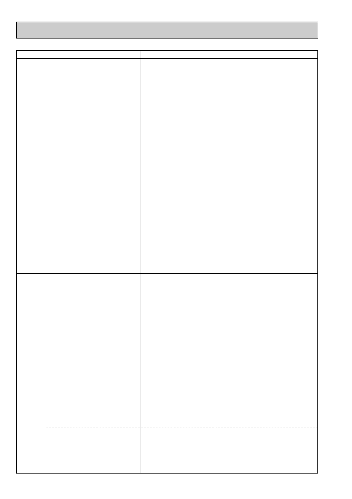
Error Code
P6
Meaning of error code and detection method
Freezing/overheating protection is
working
1 Freezing protection (Cooling mode)
The unit is in six-minute resume prevention
mode if pipe temperature stays under
-15: for three minutes, three minutes
after the compressor started. Abnormal
if it stays under -15: for three minutes
again within 16 minutes after six-minute
resume prevention mode.
<Frost prevention mode>
If pipe temperature is 1: or below
when 16 minutes has passed after compressor starts operating, unit will start
operating in frost prevention mode which
stops compressor operation. After that,
when pipe temperature stays 10: or
more for 3 minutes, frost prevention
mode will be released and compressor
will restart its operation.
2 Overheating protection (Heating mode)
The units is in six-minute resume
prevention mode if pipe temperature is
detected as over 70: after the compressor started. Abnormal if the temperature of over 70: is detected again
within 10 minutes after six-minute
resume prevention mode.
(Cooling or drying mode)
1 Clogged filter (reduced airflow)
2 Short cycle of air path
3 Low-load (low temperature)
4 Defective indoor fan motor
• Fan motor is defective.
• Indoor controller board is
5 Defective outdoor fan control
6 Overcharge of refrigerant
7 Defective refrigerant circuit
(Heating mode)
1 Clogged filter (reduced airflow)
2 Short cycle of air path
3 Over-load (high temperature)
4 Defective indoor fan motor
• Fan motor is defective.
• Indoor controller board is
5 Defective outdoor fan control
6 Overcharge of refrigerant
7 Defective refrigerant circuit
8 Bypass circuit of outdoor unit
Cause
operation beyond the tolerance
range
defective.
(clogs)
operation beyond the tolerance
range
defective.
(clogs)
is defective.
Countermeasure
(Cooling or drying mode)
1 Check clogs of the filter.
2 Remove shields.
4 Measure the resistance of fan motor's winding.
Measure the output voltage of fan's connector
(FAN) onthe indoor controller board.
WThe indoor controller board should be
normal when voltage of AC 220~240V is
detected while fan motor is connected.
Refer to 8-7.
5 Check outdoor fan motor.
67 Check operating condition of refrigerant
circuit.
(Heating mode)
1 Check clogs of the filter.
2 Remove shields.
4 Measure the resistance of fan motor's
winding.
Measure the output voltage of fan's connector
(FAN) on the indoor controller board.
WThe indoor controller board should be
normal when voltage of AC 220~240V is
detected while fan motor is connected.
Refer to 8-7.
5 Check outdoor fan motor.
6~8Check operating condition of refrigerant
circuit.
P8
Abnormality of pipe temperature
<Cooling mode>
Detected as abnormal when the pipe temperature is not in the cooling range 3 minutes later of compressor start and 6 minutes later of the liquid pipe is out of cooling
range.
Note 1) It takes at least 9 min. to detect.
Note 2) Abnormality P8 is not detected in
drying mode.
Cooling range : -5 deg ] (TH2-TH1)
TH2: Liquid pipe temperature
TH1: Intake temperature
<Heating mode>
When 10 seconds have passed after the
compressor starts operation and the hot
adjustment mode has finished, the unit is
detected as abnormal when
condenser/evaporator pipe temperature is
not in heating range within 20 minutes.
Note 3) It takes at least 27 minutes to
detect abnormality.
Note 4) It excludes the period of defrosting
(Detection restarts when defrosting
mode is over)
Heating range : 5 deg [ (TH2-TH1)
Abnormality in outdoor unit
1 Slight temperature difference
between indoor room
temperature and pipe temperature thermistor
• Shortage of refrigerant
• Disconnected holder of pipe
thermistor
• Defective refrigerant circuit
2 Converse connection of
extension pipe (on plural units
connection)
3 Converse wiring of indoor/
outdoor unit connecting wire
(on plural units connection)
4 Defective detection of indoor
room temperature and pipe
temperature thermistor
5 Stop valve is not opened
completely.
1 Wrong wiring of indoor/outdoor
connecting wire
2 Reversed phase
3 Protection device is working
4 Damaged outdoor coil thermis-
tor
1~4 Check pipe temperature with room
temperature display on remote
controller.
23Check converse connection of extension
pipe or converse wiring of indoor/outdoor
unit connecting wire.
1 Check the indoor/outdoor connecting wire.
2 Change the connection of electric wiring.
3 Check the protection device.
4 Measure the resistance of the outdoor coil
thermistor. If the resistance is normal,
replace the outdoor controller board.
28
Page 29

Error Code
E0
or
E4
E3
or
E5
Meaning of error code and detection method
Remote controller transmission
error(E0)/signal receiving error(E4)
1 Abnormal if main or sub remote con-
troller can not receive normally any
transmission from indoor unit of refrigerant address “0” for three minutes.
(Error code : E0)
2 Abnormal if sub remote controller could
not receive for any signal for two minutes. (Error code: E0)
1 Abnormal if indoor controller board can
not receive normally any data from
remote controller board or from other
indoor controller board for three minutes.
(Error code: E4)
2 Indoor controller board cannot receive
any signal from remote controller for two
minutes. (Error code: E4)
Remote controller transmission
error(E3)/signal receiving error(E5)
1 Abnormal if remote controller could not
find blank of transmission path for six
seconds and could not transmit.
(Error code: E3)
2 Remote controller receives transmitted
data at the same time, compares the
data, and when detecting it, judges
different data to be abnormal 30
continuous times. (Error code: E3)
1 Abnormal if indoor controller board could
not find blank of transmission path.
(Error code: E5)
2 Indoor controller board receives trans-
mitted data at the same time, compares
the data,and when detecting it, judges
different data to be abnormal 30
continuous times. (Error code: E5)
1 Contact failure at transmission
2 All remote controllers are set
3 Mis-wiring of remote controller.
4 Defective transmitting receiving
5 Defective transmitting receiving
6 Noise has entered into the
1 Two remote controller are set
2 Remote controller is connected
3 Repetition of refrigerant
4 Defective transmitting receiving
5 Defective transmitting receiving
6 Noise has entered into trans-
Cause
wire of remote controller
as “sub” remote controller. In
this case, E0 is displayed on
remote controller, and E4 is
displayed at LED (LED1, LED2)
on the outdoor controller circuit
board.
circuit of remote controller
circuit of indoor controller board
of refrigerant address “0”.
transmission wire of remote
controller.
as “main.”
(In case of 2 remote con-
trollers)
with two indoor units or more.
address.
circuit of remote controller.
circuit of indoor controller
board.
mission wire of remote con-
troller.
Countermeasure
1 Check disconnection or looseness of indoor
unit or transmission wire of remote controller.
2 Set one of the remote controllers “main”.
If there is no problem with the action above.
3 Check wiring of remote controller.
• Total wiring length: max.500m
(Do not use cable x 3 or more)
• The number of connecting indoor units:
max.16units
• The number of connecting remote controller: max.2units
When it is not the above-mentioned problem of
1~3
4 Diagnose remote controllers.
a) When “RC OK” is displayed,
Remote controllers have no problem.
Put the power off, and on again to check.
If abnormality generates again, replace
indoor controller board.
b) When “RC NG” is displayed,
Replace remote controller.
c) When “RC E3” is displayed,
d) When “ERC 00-06” is displayed,
[ c),d)→Noise may be causing abnormality. ]
∗ If the unit is not normal after replacing
indoor controller board in group control,
indoor controller board of address “0”
may be abnormal.
1 Set a remote controller to main, and the
other to sub.
2 Remote controller is connected with only one
indoor unit.
3 The address changes to a separate setting.
4~6 Diagnose remote controller.
a) When “RC OK”is displayed, remote con-
trollers have no problem.
Put the power off,and on again to check.
When becoming abnormal again, replace
indoor controller board.
b)When “RC NG”is displayed, replace
remote controller.
c)When “RC E3”or “ERC 00-66”is displayed,
noise may be causing abnormality.
29
Page 30

Error Code
Fb
E1
or
E2
PA
(2502)
(2500)
Meaning of error code and detection method
Abnormality of indoor controller board
Abnormal if data cannot be normally read
from the nonvolatile memory of the indoor
controller board.
Abnormality of remote controller control board
1 Abnormal if data cannot be normally
read from the nonvolatile memory of the
remote controller control board.
(Error code: E1)
2 Abnormal if the clock function of remote
controller cannot be normally operated.
(Error code: E2)
Forced compressor stop
(due to water leakage abnormality)
1 When the intake temperature subtracted
with liquid pipe temperature is less than
-10:, drain sensor is detected whether
it is soaked in the water or not at the interval
of 90 seconds. (Drain pump will start operating
when the drain sensor is detected to be
soaked in the water.)
2 The unit has a water leakage abnormality
when the following conditions, a and b, are
satisfied while the above-mentioned detection
is performed.
a) The drain sensor is detected to be
soaked in the water 10 times in a row.
b) The intake temperature subtracted with
liquid pipe temperature is detected to be
less than -10: for a total of 30 minutes.
(When the drain sensor is detected to
be NOT soaked in the water, the detection
record of a and b will be cleared.)
3 The drain sensor detection is performed
in operations other than cooling. (When
the unit stops operating, during heating
or fan operation, when the unit stops
because of some abnormality)
*Once the water leakage abnormality is
detected, abnormality state will not be
released until the main power is reset.
1 Defective indoor controller
1 Defective remote controller. 1 Replace remote controller.
1 Drain pump trouble
2 Drain defective
3 Open circuit of drain sensor
4 Contact failure of drain sensor
5 Dew condensation on drain
6 Extension piping connection
7 Mis-wiring of indoor/ outdoor
8 Room temperature thermistor /
Cause
board.
· Drain pump clogging
· Drain pipe clogging
side heater
connector
sensor
· Drain water descends along
lead wire.
· Drain water waving due to filter
clogging.
difference at twin, triple,
quadruple system.
connecting at twin, triple,
quadruple system.
liquid pipe temperature thermistor detection is defective.
Countermeasure
1 Replace indoor controller board.
Check the drain pump.
Performance
Please confirm whether water can be drained.
Confirm the resistance of the drain sensor side
heater.
Check the connector contact failure.
1 Check the drain sensor leadwire mounted.
2 Check the filter clogging
Check the piping connection.
Check the indoor/ outdoor connecting wires.
Check the room temperature display of remote
controller.
Check the indoor liquid pipe temperature display of outdoor controller board.
30
Page 31

8-4. TROUBLESHOOTING BY INFERIOR PHENOMENA
Phenomena
(1)LED2 on indoor controller board
is off.
• When LED1 on indoor controller board is also off.
1 Power supply of 220~240V AC is not supplied to
indoor unit.
2 Defective indoor controller board.
3 Defective indoor power board.
Cause
Countermeasure
1 Check the voltage of indoor power supply
terminal block (L,N).
• When AC220~240V is not detected.
Check the power supply wiring.
• When AC220~240V is detected.
-Check 2 (below).
2 Check voltage output from CNDK on
indoor controller board.
• When AC220~240V is not detected.
Check the fuse on indoor controller
board.
Check the wiring connection between
indoor power supply terminal block and
CND on indoor controller board.
• When AC220~240V is detected.
-Check 3 (below).
3 Check voltage output from CN2S on
indoor power board.
• When no voltage output.
Check the wiring connection between
CNDK on indoor controller board and
CNSK on indoor power board.
If no problem are found,indoor power
board is defective.
• When DC12.5~13.7V is detected.
Check the wiring connection between
CN2S on indoor power board and
CN2D on indoor power board.
If no problem are found,indoor con-
troller board is defective.
(2)LED2 on indoor controller board
is blinking.
• When LED1 on indoor controller board is lit.
1 Mis-setting of main/sub for indoor unit
(There is no unit corresponding to main unit.)
• When LED1 on indoor controller board is also blinking.
Connection failure of indoor/outdoor unit connecting
wire
• When LED1 is lit.
1 Mis-wiring of remote controller wires
When 2 indoor units are wired in one refrigerant
system, each indoor unit sets main unit. (SW5-3)
2 Short-cut of indoor/outdoor unit connecting wire.
3 Short-cut of remote controller wires
4 Defective remote controller
1 Reconfirm the setting of main/sub for
indoor unit
Set the main unit.
Set main/sub using SW5-3 on indoor
controller board.
Check indoor/outdoor unit connecting wire
for connection failure.
1 Check the connection of remote con-
troller wires in case of twin triple indoor
unit system. When 2 or more indoor units
are wired in one refrigerant system,
connect remote controller wires to one of
those units.
2 Remove indoor/outdoor connecting wires
and check LED2 on indoor controller
board.
• When LED2 is blinking, check the shortcut of indoor/outdoor connecting wires.
• When LED2 is lit, connect indoor/outdoor
connecting wires again, and; if LED2 is
blinking, outdoor unit’s controller board is
defective; if LED2 is lit, connection failure
of indoor/outdoor terminal block etc. has
returned to normal.
34 Remove remote controller wires and
check LED2 on indoor controller board.
• When LED2 is blinking, check the
short-cut of remote controller wires.
• When LED2 is lit, connect remote
controller wires again and:
if LED2 is blinking, remote controller
is defective; if LED2 is lit, connection
failure of remote controller terminal
block etc. has returned to normal.
31
Page 32

Phenomena
After completing installation and the wiring and piping of the indoor and outdoor units, check for refrigerant leakage,
looseness in the power supply or control wiring, wrong polarity, and no disconnection of one phase in the supply.
Use a 500-volt megohmmeter to check that the resistance between the power supply terminals and ground is at least 1.0M".
Do not carry out this test on the control wiring (low voltage circuit) terminals.
Warning:
Do not use the air conditioner if the insulation resistance is less than 1.0M".
▲▲▲
B
EF
C
H
G
IM
A
D
ûC
ûC
SIMPLE
PAR-21MAA
ON/OFF
FILTER
CHECK
OPERATION
CLEAR
TEST
TEMP.
MENU
BACK DAY
MONITOR/SET
CLOCK
ON/OFF
TEST RUN
COOL, HEAT
A ON/OFF button
B Test run display
C Indoor temperature liquid line
temperature display
D ON/OFF lamp
E Power display
F Error code display
Test run remaining time display
G Set temperature button
H Mode selection button
I Fan speed button
M TEST button
1 Turn on the power at least 12 hours before the test run.
2 Press the [TEST] button twice. ➜ "TEST RUN" liquid crystal display
3 Press the [Mode selection] button. Make sure that wind is blown out.
4 Press the [Mode selection] button and switch to the cooling (or heating) mode.
➜ Make sure that cold (or warm) wind is blown out.
5 Press the [Fan speed] button. ➜ Make sure that the wind speed is switched.
6 Check operation of the outdoor unit fan.
7 Release test run by pressing the [ON/OFF] button. ➜ Stop
8 Register a telephone number.
The telephone number of the repair shop, sales office, etc., to contact if an error
occurs can be registered in the remote controller. The telephone number will be
displayed when an error occurs. For registration procedures, refer to the operation
manual for the indoor unit.
[Emergency operation procedure]
1.When the indoor unit microcomputer has failed, but all other components work properly, if you set the switch(SWE,SW6)on the
indoor control board, the indoor unit will begin Emergency Operation.
2.When you activate emergency operation of the cooling or heating, you have to set the switch(SWE)and switch(SW6)on indoor
controller.
SWE:ON · Indoor fan is running high speed.
SW6-1:ON · Emergency operation of cooling mode.
SW6-1,2:ON · Emergency operation of heating mode.
3.Before you activate emergency operation, check the following points:
(1) Emergency operation cannot be activated when:
· The outdoor unit malfunctions. · The indoor fan malfunctions.
(2) Emergency operation becomes continuous only by switching the power source on / off. ON / OFF on the remote control or temperature
control etc. does not function.
(3) Avoid operating for a long time when the outdoor unit begins defrosting while emergency operation of the heating is activated,
because it will start to blow cold air.
(4) Emergency cooling should be limited to 10 hours maximum(The indoor unit heat exchanger may freeze).
(5) After emergency operation has been deactivated, set the switches etc. to their original positions.
(6) Movement of the vanes does not work in emergency operation, therefore you have to slowly set them manually to the appropriate
position.
(3)Upward/downward vane
performance failure
1 The vane is not downward during defrosting and
heat preparation and when the thermostat is OFF in
HEAT mode. (Working of COOL protection function)
Cause
2 Vane motor does not rotate.
• Defective vane motor
• Breaking of wire or connection failure of connector
• Up/down vane setting is “No vanes”.
3 Upward/downward vane does not work.
• The vane is set to fixed position.
(4)Receiver for wireless remote
controller
1 Weak batteries of wireless remote controller.
2 Contact failure of connector (CNB) on wireless
remote controller board.
(Insert failure)
3 Contact failure of connector (CN90) on indoor con-
troller board.(Insert failure)
4 Contact failure of connector between wireless
remote controller board and indoor controller board.
8-5. TEST RUN AND EMERGENCY OPERATION
8-5-1. Before test run
Countermeasure
1 Normal operation (The vane is set to hor-
izontal regardless of remote control.)
2 Check 2 (left).
• Check the vane motor. (Refer to “How
to check the parts”.)
• Check for breaking of wire or connection failure of connector.
• Check “Up/down vane setting”. (Unit
function selection by remote controller).
3 Normal operation (Each connector on
vane motor side is disconnected.)
1 Replace batteries of wireless remote con-
troller.
2~4
Check contact failure of each connector.
If no problems are found of connector,
replace indoor controller board.
When the same trouble occurs even if
indoor controller board is replaced,
replace wireless remote controller
board.
8-5-2. Test run (Using wired remote controller)
8-5-3. When wired remote controller or indoor unit micro computer troubles
32
Page 33
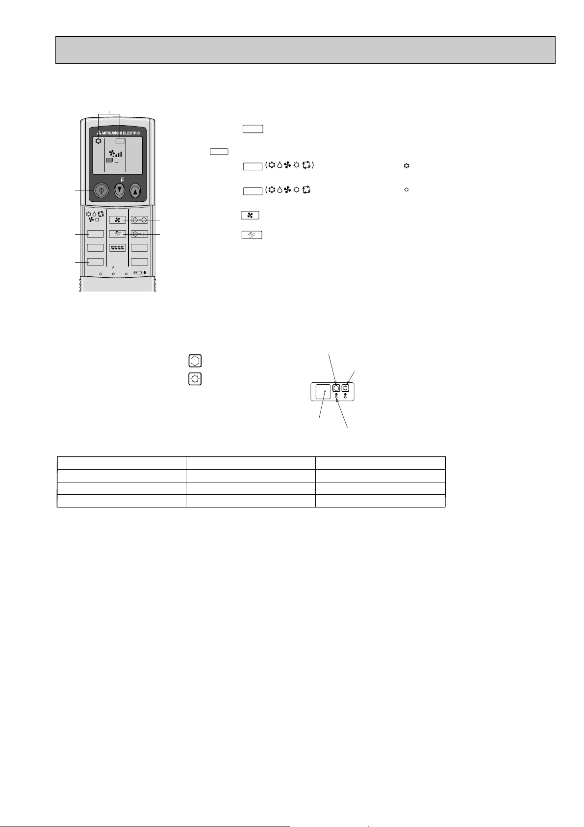
Mode
Cooling
Heating
Set temperature
Fan speed
Airflow direction
24:
High
Downward (70deg)
24:
High
Horizontal (30deg)
wEmergency operation will be performed as follows.
8-5-4. Test run (Using wireless remote controller)
3,4
7
2
A
ON/OFF TEMP
FAN
VANE
MODE
LOUVER
CHECK
TEST RUN
RESETSET CLOCK
TEST RUN
AUTO STOP
AUTO START
min
5
6
h
1 Turn on the power to the unit at least 12 hours before the test run.
2 Press the button twice continuously.
TEST RUN
(Start this operation from the status of remote controller display turned off.)
A and current operation mode are displayed.
TEST RUN
3 Press the button to activate mode, then check whether
cool air is blown out from the unit.
4 Press the button to activate mode, then check whether
cool air is blown out from the unit.
5 Press the button and check whether fan speed changes.
6 Press the button and check whether the auto vane operates properly.
MODE
MODE
FAN
VANE
COOL
HEAT
7 Press the ON/OFF button to stop the test run.
Note:
•
Point the remote controller towards the indoor unit receiver while following steps 2 to 6.
• It is not possible to run the in FAN or DRY mode.
8-5-5. When wireless remote controller troubles or its battery is exhausted
1. Emergency operation is available in such a case using emergency operation switch equipped next to the receiver of indoor
unit.
2. To start operation
• Cooling Operation·······Press (Cooling) switch.
• Heating Operation·······Press (Heating) switch.
wWhen the unit starts operating, the operation lamp is lit.
Emergency operation switch (cooling)
Emergency operation switch (heating)
3. To stop operation
• Press either emergency operation switch (cooling/heating).
Receiver
Operation lamp
33
Page 34

Room temperature
thermistor
(TH1)
(TH2)
Pipe temperature
thermistor
Fan motor (MF)
Disconnect the connector, then measure the resistance using a tester.
(Surrounding temperature 10:~30:)
Measure the resistance between the terminals using a tester.
(Refer to the thermistor)
Normal
4.3k"~9.6k"
Abnormal
Open or short
Motor terminal
or
Relay connector
Normal
PKH-GAKLH, PKH-GAKL
1.6/2
Abnormal
Red-Black
141.2"
Open or short
White-Black
131.5"
Protector
Parts name Check points
0
10
20
30
40
50
-20 -10 0 10 20 30 40 50
< Thermistor for lower temperature >
Temperature (:)
Resistance (K")
<Thermistor Characteristic graph>
Room temperature thermistor(T H1)
Pipe temperature thermistor(T H2)
Thermistor R0=15k" ± 3%
Fixed number of B=3480 ± 2%
Rt=15exp { 3480( ) }
0: 15k"
10: 9.6k"
20: 6.3k"
25: 5.2k"
30: 4.3k"
40: 3.0k"
Thermistor for
lower temperature
1
273+t
1
273
Vane motor (MV)
Measure the resistance between the terminals using a tester.
(Surrounding temperature 20:~30:)
Normal
186~214"
Abnormal
Open or short
3 6 1
4
5
2
M
Pink
Connector
Red
Orange
Blue
Brown
Yellow
Brown-Yellow
Brown-Blue
Red-Orange
Red-Pink
8-6. HOW TO CHECK THE PARTS
PKH-1.6GAKL PKH-2GAKL
PKH-1.6GAKLH PKH-2GAKLH
Relay connector
3
2
1
Red
White
Black
1
3
C
5
34
Page 35

8-7.TEST POINT DIAGRAM
8-7-1. Power board
PKH-1.6GAKL PKH-2GAKL
PKH-1.6GAKLH PKH-2GAKLH
CN2S
Connect to the indoor controller board (CN2D)
11
Between
33
to
12.6-13.7V DC (Pin11(+))
CNSK
Connect to the indoor controller board
(CNDK)
Between
11
to 33220-240V AC
35
Page 36

8-7-2. Indoor controller board
PKH-1.6GAKL PKH-2GAKL
PKH-1.6GAKLH PKH-2GAKLH
CNDK
Connect to the indoor
power board (CNSK)
(220~240V AC)
FUSE
(6.3 A 250 V)
CND
Power supply input
(220~240V AC)
CNP
Drain-pump output
(DP)
(220~240V AC)
CN2D
Connect to the indoor
power board (CN2S)
(12.5~13.7V DC)
LED1
Power supply (I.B)
LED2
Power supply (R.B)
SW6
Emergency
operation
CN22
Connect to the terminal
block(TB5)
(Remote controller connecting
wire)
(10.4~14.6V DC)
CN30
Transmission
(Indoor/outdoor)
CN20
Room temperature
thermistor (TH1)
CN21
Pipe temperature
thermistor/Liquid (TH2)
CN31
Drain sensor (DS)
CN90
Connect to the wireless
remote controller board
(CNB)
CN6V
Vane motor output
(MV)
CN41
Connector (HA terminal-A)
CN51
Centrally control
SWE
Emergency operation
FAN
Fan motor output
Jumper wire J41, J42
Pair number setting with
wireless remote controller
36
SW2
Capacity setting
CN105/92
(RED)
CN24
Heater output
(12V DC)
CN32
Remote switch
CN2L
Connector
(LOSSNAY)
SW5
System setting
SW1
Model setting
Page 37

SW1
Setting by the dip switch and jumper wire
Functions
Jumper wire
Model
settings
SW5
System
settings
Capacity
settings
Pair number
setting with
wireless
remote
controller
Remarks
SW2
J41
J42
0
1
2
3 ~ 9
Wireless remote
controller setting
Control PCB setting
J41 J42
<Settings at time of factory shipment>
Wireless remote controller: 0
Control PCB: (for both J41 and J42)
Four pair number settings are supported.
The pair number settings of the wireless remote
controller and indoor control PCB (J41/J42) are
given in the table on the left.
(' ' in the table indicates the jumper line is disconnected.)
SW5-3 Main/Sub setting
OFF : Main ON : Sub
SW5-4 Rotaion operation setting
OFF : Not avairable ON : avairable
SW2
1 2 3 4 5
ON
OFF
MODELS
PKH-1.6GAKL(H)
1 2 3 4 5
ON
OFF
PKH-2GAKL(H)
1 2 3 4 5
ON
OFF
1 2 3 4 5 6 7 8
ON
OFF
8-8. FUNCTIONS OF DIP SWITCH AND JUMPER WIRE
Each function is controlled by the dip switch and the jumper wire on control p.c. board.
3737
Page 38

8-9. OUTDOOR UNIT SERVICE FUNCTIONS (OUTDOOR CONTROLLER BOARD)
(1) Compulsory defrosting
1When all of the following conditions are satisfied, pressing SW2 starts the compulsory defrosting.
● During HEAT mode
● The compressor is ON.
● The outdoor coil temperature is being displayed by LED. (Outdoor controller board dip switch SW3-1 : OFF, SW3-2 :
ON)
● The outdoor coil thermistor reads 8°C or below.
2The operation state and the termination conditions of the compulsory defrosting are the same as those of the normal
defrosting. As an exception, the defrost interval after the defrosting completion is 50 minutes.
(2) Fixed fan-output
While the compressor is operating (except during defrosting) and the fan output step is indicated by LED, pressing SW2
fixes the fan output. The fixed fan-output can be released when any of the following conditions are satisfied.
1SW2 is pressed again.
2SW3 setting is changed.
3The compressor stops.
4Defrosting operation starts.
(3) Function of switches on the outdoor controller board
SW1: Clears the check code memory (push-button switch)
SW2: Switches the output state indication and the check code display (push-button switch)
SW3-1,2: Switches the output state indication items (dip switch)
(4) 100% fan output
Fan output is fixed to 100% by shorting the connector CN22. However, the fan stops during compressor OFF or defrosting.
Open-circuit of CN22 restarts the normal fan control.
(5) Time shortening
Short circuit of the connector CN21 shortens the time as follows
1Fan control period: 30 seconds → 3 seconds
2Three-minutes time delay function : 3 minutes → 3 seconds
3Max. time of defrosting : 15 minutes → 15 seconds
4Defrost interval : 30 ~ 120 minutes → 3 ~ 12 seconds
5Compressor ON/OFF time for bypass valve ON/OFF : 30 minutes → 3 seconds
6Compressor ON time to start other functions : x minutes → x seconds
7Crankcase heater operation : 1 hour → 6 seconds
(6) Crankcase heater control
1With jumper wire J3
The crankcase heater is ON from when the power is turned ON until the compressor starts, and then turns ON one hour
after the compressor stops.
2Without jumper wire J3
The crankcase heater is ON from when the power is turned ON until the compressor starts, and repeats 1-hour ON and 1hour OFF, after the compressor stops.
38
Page 39
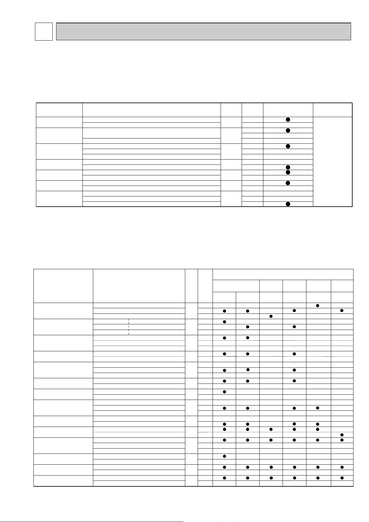
9
Function Settings
No.
Mode
No.
Setting
Initial setting (Factory setting
)
- : Not available
4-Way cassette
Ceiling
concealed
Ceiling
suspended
Wall
mounted
Floor
standing
PLH-AAK(H)
PEH-EAK(H)
PCH-GAK(H)
PKHGAKL(H)
PSH-GAK(H)
PEHD-EAK(H)
PKA-FAKL(H)
Filter sign 100Hr 1
2500Hr 07 2
No filter sign indicator
3
Air flow Quiet Standard 1 - - (
Fan speed
)
Standard
High ceiling1
08 2 - - -
High ceiling
High ceiling2
3--No.of air outlets 4 directions 1 - - - -
3 directions 09 2 - - - 2 directions
3----Optional high efficiency
Not supported
10
1
---
filter Supported
2
---
Vane setting
No vanes (Vane No.3 setting:PLH-AAK(H)only
)
1---
Vane No.1 setting
11 2 - - -
Vane No.2 setting
3--Energy saving air Disabled
12
1
---
flow (Heating mode
)
Enabled
2
---
Optional humidifier Not supported
13
1
--- -
(
PLH-AAK(H) only
)
Supported
2
--- -
Vane differential setting No.1 setting (TH2: 24-28:
)
1- in heating mode No.2 setting (Standard, TH2: 28-32:
)
14 2 - -
(
cold wind prevention
)
No.3 setting (TH2: 32-38:
)
3- Swing Not available
23
1
--
Available
2
--
Set temperature in heating Available
24
1
mode (4 deg up
)
Not available
2
Fan speed when the Extra low 1
heating thermostat is OFF
Stop
25 2
Set fan speed
3
Quiet operation mode Disabled (Standard
)
26
1
--- -
of PLH-AAK(H)(Fan speed)Enabled (Quiet operation mode
)
2
--- -
Fan speed when the
Set fan speed
27
1
cooling thermostat is OFF Stop
2
Detection of abnormality of Available
28
1
the pipe temperature (P8)Not available
2
}
PLH-AAK(H)
PLH-KAK(H)
-
-
-
-
Function
Settings
Mode No.
Setting No.
Initial setting
(when sent from the factory)
Remarks
Power failure
automatic recovery
Indoor temperature
detecting
LOSSNAY
connectivity
Power supply
voltage
Frost prevention
temperature
Humidifier control
Rotation
OFF
ON
Indoor unit's (Main) internal sensor
Remote controller's internal sensor w1
Not supported
Supported (indoor unit not equipped with outdoor air intake)
Supported (indoor unit equipped with outdoor air intake)
240V
220V,230V
1: (Normal)
-3:
When the compressor operates, the humidifier also operates.
When the fan operates, the humidifier also operates.
24h cycle
168h cycle
Back up function
1
2
1
2
3
1
2
3
1
2
1
2
1
2
1
2
3
01
02
03
04
15
16
20
The setting is
applied to all
the units in the
same
refrigerant
system.
FUNCTION SETTING
9-1. UNIT FUNCTION SETTING BY THE REMOTE CONTROLLER
Each function can be set according to necessity using the remote controller. The setting of function for each unit can only be
done by the remote controller. Select function available from the table 1.
<Table 1> Function selections
(1) Functions available when setting the unit number to 00 (Select 00 referring to 4 setting the indoor unit number.)
W1 The functions below are available only when the wired remote controller is used.The functions are not available for floor
standing models.
(2) Functions available when setting the unit number to 01-03 or AL (07 in case of wireless remote controller)
• When setting functions for an indoor unit in an independent system, set the unit number to 01 referring to 4 setting the
indoor unit number.
• When setting functions for a simultaneous- Twin indoor unit system, set the unit number to 01 to 02 for each indoor
unit in case of selecting different functions for each unit referring to 4 setting the indoor unit number.
• When setting the same functions for an entire simultaneous Twin indoor unit system, set refrigerant address to AL
(07 in case of wireless remote controller) referring to 4 setting the indoor unit number.
39
Page 40

Rotation setting (Function setting mode No.20
)
Function setting
Features Indoor controller board
Mode No.
This system can correspond only by the pattern of two refrigerant group by 1 : 1
(indoor and outdoor unit combination) systems.
Setting No.
SW5-3 setting SW5-4 setting
20
01
(
24hours cycle
)
02
ON
OFF : Main
ON : Sub
(
168hours cycle
)
03
(
Back up
function
)
When abnormality occurs while
operating
,
it changes as a back up unit
,
and operating continues.
Each system operates alternately for
24hours.
Each system operates alternately for
168hours.
Example of unit's operation
(Setting No. = 01 or 02)
Main Unit is abnormal
Operation starts Main➝Sub Sub➝Main
(Setting No. = 02
• • •
168hours cycle)
Outdoor
unit
(Setting No. = 03)
Main Unit is abnormal
Indoor
Operation starts Main➝Sub
unit
Remote
Controller
Main➝Sub
ON
OFF
OFF
Main
ON
OFF
ON
ON
OFF
9-1-1. Selecting functions using the wired remote controller
First, try to familiarize yourself with the flow of the function selection procedure. In this section, an example of setting the room
temperature detection position is given.
For actual operations, refer to steps 1 to 0 .
Setting number
Address Unit number
Mode number
F
E
G
C
D
J
B
A
I
Modes 01 to 13 can be activated
by pressing buttons
A
and
B
simultaneously, and modes 15 to
28 by pressing buttons
B
and J.
indoor
unit
Sub
indoor
unit
24h 24h
Main
Main
indoor
unit
Sub
indoor
unit
Sub
40
Page 41

The below procedure must be carried out only if changes are necessary.
Selecting functions using the wired remote controller
1
Check the function selection setting.
2
Switch to function setting mode.
(Press
A
and B at the same time
For modes 15 and higher,
press
J
and B at the same time.
with the remote controller stopped.)
3
Specify address
(Use
C
4
Specify unit No.
and D.)
Refer to address unit No. to the figure below
5
Enter the setting.
(Press
6
Select mode No. 02
(Specified indoor unit:
E
.)
BLOW operation)
NO
Change refrigerant
address unit No.
YES
(room temperature detection position).
7
Select setting No. 03 (remote controller fixed).
(Use
F
and G.)
8
Enter the setting.
(Press
E
.)
Example:
Selecting room temperature
detection position
9
NO
Finished
YES
0
Ending function display
(Press
1 : 1 system Simultaneous twin system Rotation system
A
and B at the same time.)
Outdoor unit
Outdoor unit Outdoor unit Outdoor unit
Indoor unit
Remote controller
Indoor unit
address = 00
unit No. = 01
Main
indoor unit
Main indoor unit
address = 00
unit No. = 01
Sub
indoor unit
Remote controller
Sub indoor unit
address = 01
unit No. = 02
41
Main
indoor unit
Main indoor unit
address = 00
unit No. = 01
Sub
indoor unit
Remote controller
Sub indoor unit
address = 01
unit No. = 01
Page 42

[Operating Procedure]
1 Check the setting items provided by function selection.
If settings for a mode are changed by function selection, the functions of that mode will be changed accordingly. Check all the current settings according to steps 2
to 7 , fill in the "Check" column in Table 1, and then change them as necessary. For factory settings, refer to the indoor unit's installation manual.
2 Switch off the remote controller.
A Hold down the
B and ( mode 15 or more)
buttons
simultaneously for at least two seconds.
will start to flash,
and then the remote controller's display content will change as shown below.
3 Set the outdoor address.
C Press the [ CLOCK] buttons ( and ) to select the desired
address. The address changes from "00" to "15".
* If the unit stops after
flashed for two seconds or "88" flashes in the room temperature display area for two seconds, a transmission error may have occurred.
Check to see if there are any sources of noise or interference near the transmission path.
Note
If you have made operational mistakes during this procedure, exit function selection (see step 0 ), and then restart from step 2.
4 Set the indoor unit number.
D Press the
button so that " - -" flashes in the unit number display
area.
C Press the [
CLOCK] buttons ( and ) to select the unit number
of the indoor unit for which you want to perform function selection. The unit
number changes to "00", "01", "02","03",04" and "AL" each time a button is
pressed.
* To set modes 01 to 06 or 15 to 22 select unit number "00".
* To set modes 07 to 14 or 23 to 28 carry out as follows:
• To set each indoor unit individually, select "01" to "04".
• To set all the indoor units collectively, select "AL".
5 Confirm the address and unit number.
E Press the
button to confirm the address and unit
number.
After a while, "- - " will start to flash in the mode number display area.
E When the address and unit number are confirmed by pressing the
button, the corresponding indoor unit will start fan operation. This
helps you find the location of the indoor unit for which you want to perform function
selection. However, if "00" or "AL" is selected as the unit number, all the indoor
units corresponding to the specified address will start fan operation.
* "88" will flash in the room temperature display area if the selected address
does not exist in the system.
Furthermore, if
"F"
appears and flashes in the unit number display area and the
address display area also flashes, there are no units that correspond to the
selected unit number. In this case, the address and unit number may be incorrect,
so repeat steps 2 and 3 to set the correct ones.
* When grouping different systems, if an indoor unit other than the
one to which the address has been set performs fan operation,
there may be another address that is the same as the specified one.
In this case, check the DIP switch of the outdoor unit to see
whether such a address exists.
6 Select the mode number.
F Press the [
TEMP] buttons ( and ) to set the desired mode
number.
(Only the selectable mode numbers can be selected.)
7 Select the setting content for the selected mode.
G Press the
button. The currently selected setting number will
flash, so check the currently set content.
F Press the [
TEMP] buttons ( and ) to select the desired setting
number.
8 Register the settings you have made in steps 3 to 7 .
E Press the
button. The mode number and setting number will start
to flash and registration starts.
The mode number and setting number will stop flashing and remain lit, indicating the
end of registration.
* If " - - - " is displayed for both the mode number and setting number and "
" flashes in the room temperature display area, a transmission error may have occurred.
Check to see if there are any sources of noise or interference near the transmission path.
9 If you wish to continue to select other functions, repeat steps 3 to 8 .
0 Complete function selection.
A Hold down the
buttons simultaneously for at least
two seconds.
After a while, the function selection screen will disappear and the air conditioner OFF screen will reappear.
* Do not operate the remote controller for at least 30 seconds after completing
function selection. (No operations will be accepted even if they are made.)
Note
If a function of an indoor unit is changed by function selection after installation is complete, make sure that a " " mark, etc., is given in the "Check" column of Table
1 to indicate the change.
Unit number
display section
Mode number
display section
00 address
Indoor unit
Fan draft
Remote controller
Main Sub
Outdoor unit
Designate operation
Example) When the address is set to 01 and the unit number is 02.
Mode number
display section
Mode number 02 = Indoor temperature detection
Setting number display section
Setting number 3 = Remote controller built-in sensor
Setting number 1 = Indoor unit operating average
and ( mode 15 or more)
FILTER
Address
display section
FUNCTION
SELECTION
FUNCTION
SELECTION
TEST
ON/OFF
MODE
MODE
MENU
MODE
FILTER TEST
42
Page 43

ON/OFF
TEMP
FAN
VANE
MODE
CHECK
LOUVER
TEST RUN
AUTO STOP
AUTO START
h
min
CHECK
RESET
SET
CLOCK
h
CHECK
min
h
The flow of the function selection procedure is shown below. This example shows how to turn
off the function that raises the set temperature by 4 degrees during HEAT operation .
The procedure is given after the flow chart.
1 Check the function selection setting.
2 Switch to function selection mode.
(Enter address "50" in troubleshooting
mode, then press the HOUR button.)
Troubleshooting mode is the mode entered when
you press the INSPECT button twice to display
"INSPECT".
3 Specify unit No. "01" (since the function applies to unit 01).
(Set address "01" while still in troubleshooting mode, then press the MINUTE button.)
Note: You can't specify the refrigerant address.
4
Select mode No. "24" (function that raises set temperature by 4 degrees during HEAT operation).
(Set address "24" while still in troubleshooting mode, then press the HOUR button.)
6
Finished
8 End function selection mode.
(End troubleshooting mode.)
YES
NO
Note: When you switch to function selection mode
on the wireless remote controller's operation
area, the unit ends function selection mode
automatically if nothing is input for 10 minutes
or longer.
5 Select setting No. "02" (OFF).
(Set address "02" while still in troubleshooting mode, then press the HOUR button.)
Change
unit No.
YES
NO
7
9-1-2. Selecting functions using the wireless remote controller (Type C)
h
min
Functions can be selected with the wireless remote controller. Function selection using wireless remote controller is available only for refrigerant system with wireless function. Address cannot be specified by the wireless remote controller.
[Flow of function selection procedure]
[Operating instructions]
1 Check the function settings.
2 Press the button twice continuously. → CHECK is lit and “00” blinks.
Press the temp button once to set “50”. Direct the wireless remote controller toward the receiver of the indoor unit and press
the button.
3 Set the unit number.
Press the temp button to set the unit number. (Press “01” to specify the indoor unit whose unit number is 01.)
Direct the wireless remote controller toward the receiver of the indoor unit and press the button.
By setting unit number with the button, specified indoor unit starts performing fan operation.
Detect which unit is assigned to which number using this function. If unit number is set to AL, all the indoor units in same
refrigerant system start performing fan operation simultaneously.
* If a unit number that cannot be recognized by the unit is entered, 3 beeps of 0.4 seconds will be heard. Reenter the unit number
setting.
* If the signal was not received by the sensor, you will not hear a beep or a “double beep” may be heard. Reenter the unit number
setting.
4 Select a mode.
Press the temp button to set a mode. Press “24” to turn on the function that raises the set temperature by 4 degree
during heat operation. Direct the wireless remote controller toward the sensor of the indoor unit and press the button.
→ The sensor-operation indicator will flash and beeps will be heard to indicate the current setting number.
Current setting number: 1 = 1 beep (one second)
2 = 2 beeps (one second each)
* If a mode number that cannot be recognized by the unit is entered, 3 beeps of 0.4 seconds will be heard. Reenter the mode
number.
* If the signal was not received by the sensor, you will not hear a beep or a “double beep” may be heard. Reenter the mode
number.
5 Select the setting number.
Press the temp button to select the setting number. (02: Not available)
Direct the wireless remote controller toward the receiver of the indoor unit and press the button.
→ The sensor-operation indicator will flash and beeps will be heard to indicate the the setting number.
Setting number: 1 = 2 beeps (0.4 seconds each)
* If a setting number that cannot be recognized by the unit is entered, the setting will turn back to the original setting.
* If the signal was not received by the sensor, you will not hear a beep or a “double beep” may be heard. Reenter the setting number.
6 Repeat steps 4 and 5 to make an additional setting without changing unit number.
7 Repeat steps 3 to 5 to change unit number and make function settings on it.
8 Complete the function settings
Press button.
* Do not use the wireless remote controller for 30 seconds after completing the function setting.
3 = 3 beeps (one second each)
2 = 2 beeps (0.4 seconds each, repeated twice)
3 = 2 beeps (0.4 seconds each, repeated three times)
43
Page 44

9-2. FUNCTION SELECTION OF REMOTE CONTROLLER
The setting of the following remote controller functions can be changed using the remote controller function selection mode.
Change the setting when needed.
Item 1
1.Change Language
("CHANGE LANGUAGE")
2.Function limit
("FUNCTION SELECTION")
3.Mode selection
("MODE SELECTION")
4.Display change
("DISP MODE SETTING")
Item 3 (Setting content)
• Display in multiple languages is possible.
• Setting the range of operation limit (operation lock)
• Setting the use or non-use of "automatic" operation mode
• Setting the temperature adjustable range (maximum, minimum)
• Selecting main or sub remote controller
*
When two remote controllers are connected to one group, one controller must be set to sub.
• Setting the use or non-use of clock function
• Setting the timer type
• Contact number display in case of error
• Setting the telephone number
• Setting the temperature unit (: or °F) to display
• Setting the use or non-use of the display of indoor (suction) air temperature
• Setting the use or non-use of the display of "Cooling" or "Heating" display during
operation with automatic mode
Item 2
Language setting to display
(1)
Operation function limit setting (operation lock) ("LOCKING FUNCTION")
(2)
Use of automatic mode setting ("SELECT AUTO MODE")
(3)
Temperature range limit setting ("LIMIT TEMP FUNCTION")
(1)
Remote controller main/sub setting ("CONTROLLER MAIN/SUB")
(2) Use of clock setting ("CLOCK")
(3) Timer function setting ("WEEKLY TIMER")
(4) Contact number setting for error situation ("CALL.")
(1) Temperature display :/°F setting ("TEMP MODE :/°F")
(2)
Suction air temperature display setting ("ROOM TEMP DISP SELECT")
(3)
Automatic cooling/heating display setting ("AUTO MODE DISP C/H")
[Function selection flowchart] Refer to next page.
[1] Stop the air conditioner to start remote controller function selection mode. [2] Select from item1. [3] Select from item2. [4] Make the setting.
(Details are specified in item3) [5] Setting completed. [6] Change the display to the normal one. (End)
➔➔➔
➔➔
[Detailed setting]
[4] -1. CHANGE LANGUAGE setting
The language that appears on the dot display can be selected.
• Press the [
MENU] button to change the language.
1 Japanese (JP), 2English (GB), 3 German (D), 4 Spanish (E),
5 Russian (RU), 6 Italian (I), 7 Chinese (CH), 8 French (F)
[4] -2. Function limit
(1) Operation function limit setting (operation lock)
• To switch the setting, press the [ ON/OFF] button.
1 no1 : Operation lock setting is made on all buttons other than
the [
ON/OFF] button.
2 no2: Operation lock setting is made on all buttons.
3 OFF (Initial setting value) : Operation lock setting is not made
* To make the operation lock setting valid on the normal screen, it is
necessary to press buttons (Press and hold down the [FILTER]
and [ ON/OFF] buttons at the same time for two seconds.) on
the normal screen after the above setting is made..
(2) Use of automatic mode setting
When the remote controller is connected to the unit that has automatic operation mode, the following settings can be made.
• To switch the setting, press the [ ON/OFF] button.
1 ON (Initial setting value) : The automatic mode is displayed when
the operation mode is selected.
2 OFF : The automatic mode is not display
when the operation mode is selected.
[4] -3. Mode selection setting
(1) Remote controller main/sub setting
• To switch the setting, press the [ ON/OFF] button.
1 Main : The controller will be the main controller.
2 Sub : The controller will be the sub controller.
(2) Use of clock setting
• To switch the setting, press the [ ON/OFF] button.
1 ON : The clock function can be used.
2 OFF: The clock function cannot be used.
(3) Timer function setting
• To switch the setting, press the [ ON/OFF] button (Choose one of
the followings.).
1 WEEKLY TIMER (initial setting on MA deluxe):
The weekly timer can be used.
2 AUTO OFF TIMER: The auto off timer can be used.
SIMPLE TIMER (Default setting on MA smooth):
The simple timer can be used.
4
3
TIMER MODE OFF: The timer mode cannot be used.
* When the use of clock setting is OFF , the "WEEKLY TIMER" cannot be
used.
(4) Contact number setting for error situation
• To switch the setting, press the [ ON/OFF] button.
1 CALL OFF:
The set contact numbers are not displayed in case of error.
2 CALL **** *** **** : The set contact numbers are displayed in case
of error.
(3) Temperature range limit setting
After this setting is made, the temperature can be changed within the set range.
• To switch the setting, press the [ ON/OFF] button.
1 LIMIT TEMP COOL MODE :
The temperature range can be changed on cooling/dry mode.
2 LIMIT TEMP HEAT MODE :
The temperature range can be changed on heating mode.
3 LIMIT TEMP AUTO MODE :
The temperature range can be changed on automatic mode.
4 OFF (initial setting) : The temperature range limit is not active.
*
When the setting, other than OFF, is made, the temperature range limit setting
on cooling, heating and automatic mode is made at the same time. However
the range cannot be limited when the set temperature range has not changed.
•
To increase or decrease the temperature, press the [ TEMP ( ) or ( )] button.
•
To switch the upper limit setting and the lower limit setting, press the
[ ]
button. The selected setting will flash and the temperature can be set.
• Settable range
Cooling/Dry mode : Lower limit: 19 : ~ 30: Upper limit: 30 : ~ 19:
Heating mode : Lower limit: 17 : ~ 28: Upper limit: 28 : ~ 17:
Automatic mode : Lower limit: 19 : ~ 28: Upper limit: 28 : ~ 19:
CALL_ : The contact number can be set when the display is as
shown on the left.
• Setting the contact numbers
To set the contact numbers, follow the following procedures.
Move the flashing cursor to set numbers. Press the [
TEMP. ( ) and
(
)] button to move the cursor to the right (left). Press the [ CLOCK
(
) and ( )] button to set the numbers.
[4] -4. Display change setting
(1) Temperature display :/ F setting
• To switch the setting, press the [ ON/OFF] button.
1 : : The temperature unit : is used.
2 F: The temperature unit
°
°°
F is used.
(2) Suction air temperature display setting
• To switch the setting, press the [ ON/OFF] button.
1 ON : The suction air temperature is displayed.
2 OFF: The suction air temperature is not displayed.
(3) Automatic cooling/heating display setting
• To switch the setting, press the [ ON/OFF] button.
1 ON :One of "Automatic cooling" and "A utomatic heating" is display ed
under the automatic mode is running.
2 OFF: Only "Automatic" is displayed under the automatic mode.
44
Page 45

Flowchart of Function Setting
Setting language (English)
Normal display
(Display when the air condition is not running)
Hold down the E button and press the D button for 2 seconds.
Remote controller function selection mode
Item1 Item2
Change
Language
E
E
Hold down the
G
EN
button and press the D button for 2 seconds.
E
Press the operation mode button.
G
Press the TIMER MENU button.
D
Press the TIMER ON/OFF button.
Dot display
GE
ES
RU
G
IT
ZH
FR
F
TEMP.
MENU
BACK DAY
MONITOR/SET
CLOCK
ON/OFF
E
PAR-21MAA
G
OPERATION
ON/OFF
CHECK
CLEAR
I
FILTER
A
TEST
B
H
D
C
Function
selection
Mode
selection
JA
G
G
E
G
G
E
G
G
E
G
G
G
D
D
D
D
D
D
Item3
D
D
D
D
D
D
OFF
on1
on2
ON
OFF
OFF
Operation lock setting is not used.
(Initial setting value)
D
Operation lock setting is except On/Off buttons.
Operation lock setting is All buttons.
The automatic mode is displayed when the operation mode is
selected. (Initial setting value)
D
The automatic mode is not displayed when the operation mode
is selected.
The temperature range limit is not active. (Initial setting value)
D
The temperature range can be changed on cooling/dry mode.
The temperature range can be changed on heating mode.
The temperature range can be changed on automatic mode.
The remote controller will be the main controller. (Initial setting value)
D
The remote controller will be the sub controller.
ON
OFF
The clock function can be used. (Initial setting value)
D
The clock function can not be used.
Weekly timer can be used. (Initial setting value)
D
Auto off timer can be used.
Simple timer can be used.
Display
mode setting
Timer mode can not be used.
D
OFF
D
CALL-
G
G
G
G
D
:
°F
D
D
ON
OFF
D
D
ON
OFF
D
The set contact numbers are not displayed in case of error.
(Initial setting value)
D
The set contact numbers are displayed in case of error.
:
The temperature unit
D
The temperature unit °F is used.
Room air temperature is displayed. (Initial setting value)
is used. (Initial setting value)
D
Room air temperature is not displayed.
One of "Automatic cooling" and "Automatic heating" is displayed
under the automatic mode is running. (Initial setting value)
D
Only "Automatic" is displayed under the automatic mode.
45
Page 46

SYSTEM CONTROL10
System Name System Diagram Features
Parts Required in Addition to Standard System
Components (Indoor/Outdoor Units, Remote Controller)
A.Remote control-
ler operation
(Standard)
B.Remote control-
ler operation
Use of two controllers enables
operation of the air
conditioner both
from a distance
and nearby.
C.Group control
operation
Use of one remote
controller to control multiple air
conditioners with
the same settings
simultaneously.
D.Remote/local
combined control
operation
Allows start/stop
of the air conditioner from a distance, and prohibits/permits start/
stop from remote
controllers.
E.Operation by
external signal
F.
Control and remote
display by external
signal (extraction
of monitor signal)
Enables you to
display the operation state and
control start/stop
from a distance.
• There are two types of remote controllers: wired type
and wireless type.
• Simultaneous twin indoor units are started or stopped
simultaneously.
• Up to two remote controllers can be connected to
one group.
• Simultaneous twin units are counted as each unit.
• Operation control by the latest command (last entered priority)
• Wired and wireless remote controllers can be combined as a pair.
• One group can consist of up to 16 indoor units, and
they can be started sequentially by connecting the
remote controller to them and assigning an address
to each inter face.
• Simultaneous twin units are counted as one unit.
• All the units belonging to the same group are operated in the same mode, but thermostats can be
turned ON/OFF individually for each indoor unit.
• Up to two remote controllers can be connected.
• All the air conditioners can be turned ON/OFF collectively
from a distance.
• Operation can be switched between the remote operating panel and local controller.
• Operations (e.g., temperature adjustment, airflow, airflow direction) except for start/stop operations can be
performed even if the remote controller is being operated.
• In the case of simultaneous twin units,connect the controller to one indoor unit only. If connected to two indoor
units, an error (operation stop) may occur.
• Control by an external timer is possible by connecting it.
• Use of optional "remote ON/OFF adapter" enables
remote control via relay. (Level signal)
Extraction of non-voltage contact output
• Use of optional "remote operation adapter" and
"remote display panel" (Part to be provided at your
site) provides non-voltage contact outputs of signals
(opera-tion, error) and operation/stop input function.
Extraction of DC12 V contact output
• Use of optional "remote display adapter" and "remote display panel" (Part to be provided at your site)
provides DC12 V contact outputs of signals
(operation, error) and operation/stop input function.
* One of the wired remote con-
trollers must be set as a sub
remote controller.
Wired remote controller (additional)
(PAR-21MAA)
Inter face MAC-397IF-E
Remote ON/OFF adapter
(PAC-SE55RA-E)
Relay box
(Part to be provided at your site)
Remote operating panel
(Part to be provided at your site)
Remote ON/OFF adapter
(PAC–SE55RA-E)
Remote operation adapter
(PAC-SF40RM-E)
Remote display panel
(Part to be provided at your site)
Remote display adapter
(PAC-SA88HA)
Remote display panel
(Part to be provided at your site)
10-1. VARIETY OF SYSTEM CONTROL FUNCTIONS
Indoor unit
Remote
Controller
Indoor
unit
Remote
Controller
Inter face
Indoor
unit
Outdoor
unit
Outdoor
unit
Remote
Controller
Relay box
Indoor unit
Remote Controller
Remote operating panel
Remote
display kit
Indoor unit
Remote Controller
Remote display (operation, error)
46
Page 47

System Name System Diagram Features
• Weekly timer:
In addition to ON/OFF, up to eight temperature
patterns can be set for each day of the week.
G. Timer operation
Enables control
of start and stop.
* For control by
external timer,
refer to Remote/
handheld combined control operation".
* Only one timer can be selected; the auto off, simple
and weekly timers cannot be combined.
• Simple timer: Start and stop operations can each be
performed once within 72 hours (can
be set in 1-hour increments).
• Auto off timer:Operation is stopped when the preset
time elapses following the start of
operation.
The time can be set from 30 minutes
to 4 hours in 30-minute increments.
* Only one timer can be selected; the simple and auto
off timers cannot be combined.
Parts Required in Addition to Standard System
Components (Indoor/Outdoor Units, Remote Controller)
MA Remote controller
(PAR-21MAA)
H.Interlock opera-
tion with periph-
eral equipment
Enables control of
Mitsubishi Lossnay
ventilator by remote
controller.
I.Rotation
Lossnay
ventilator
Main
Remote
Controller
Sub
Indoor unit
Remote
Controller
Indoor
unit
Outdoor
unit
• Connecting a Lossnay ventilator and an indoor unit
enables control of interlock/solo ventilation operation and airflow.
(Only the microcomputer type Lossnay ventilator
can be used.)
•
When abnormality occurs while operating, it changes
into operating the back up unit, and operating is
continued.
(Unit function Mode No. 20 setting No.3 , Indoor
controller board SW-5-4 ON)
Main / Sub setting
Main : Indoor controller board
SW5-3 : OFF
Sub : Indoor controller board
SW5-3 : ON
•
Each system operates alternately for 24 hours or 168
hours.
(Unit function Mode No. 20 setting No.1: 24 hours/
No.2 : 168 hours, Indoor controller board SW 5-4 ON)
Main / Sub setting
Main : Indoor controller board
SW5-3 : OFF
Sub : Indoor controller board
SW5-3 : ON
This system can correspond only by
the pattern of two refrigerant group
by 1 : 1 (indoor and outdoor unit
combination) systems.
47
Page 48

10-2. ONE REMOTE CONTROLLER (STANDARD) OPERATION
Slim Air Conditioners System
Remote controller
connection circuit
(Controller cable)
Outdoor unit
OC
Indoor unit
IC
Wired
remote
controller R
Indoor/Outdoor
connection
cable
Remote
controller
cable
OC
IC-1
R
IC-2
3
2
OC
IC-1
R
3
2
Standard 1:1 Simultaneous Twin Indoor controller board switch setting
SW5-3
OFF
ON
Indoor unit IC
IC-1 (Main)
IC-2 (Sub)
OC IC
1
2
LN
Power source wiring
1
2
3
1
2
R
(No polarity)
Outdoor unit Indoor unit Remote controller
Power
source
wiring
(Polarity)
1
2
3
Slim Air Conditioners System
Remote controller
optical receiver
section connection
circuit
Outdoor unit
OC
Indoor unit
IC
Wireless
remote controller
receiver section R'
Indoor/Outdoor
connection
cable
OC
IC-1
R'
IC-2
3
2
9
OC
IC-1
R'
3
9
Standard 1:1 Simultaneous Twin
Wireless remote
controller cable
Wireless remote
controller cable
Indoor controller board switch setting
SW5-3
OFF
ON
Indoor unit IC
IC-1 (Main)
IC-2 (Sub)
CN90
Controller board
Indoor unit IC
9
CNB
12
Wireless remote controller
optical receiver section R’
Remote controller
cable terminal block
(1) One Wired Remote Controller
(OC: Outdoor unit IC: Indoor unit R: Remote controller (for wireless type: optical receiver adapter)
(Reference)
11
If simultaneous twin connect the remote controller to indoor units. Can control all functions of the indoor unit even if different models (different types) are mixed. Note that there may be some restrictions of the functions.
22
Electrical wiring diagram
• Power supply terminal block L, N
• Indoor/outdoor connection cable terminal
block 1,2 (Polarity)
• Remote controller cable terminal block
1,2 (No polarity)
(2) Wireless remote controller
(Reference)
11
If simultaneous twin connect the remote controller to indoor units. Can control all functions of the indoor unit even if different models (different types) are mixed. Note that there may be some restrictions of the functions.
22
Electrical wiring diagram
48
Page 49
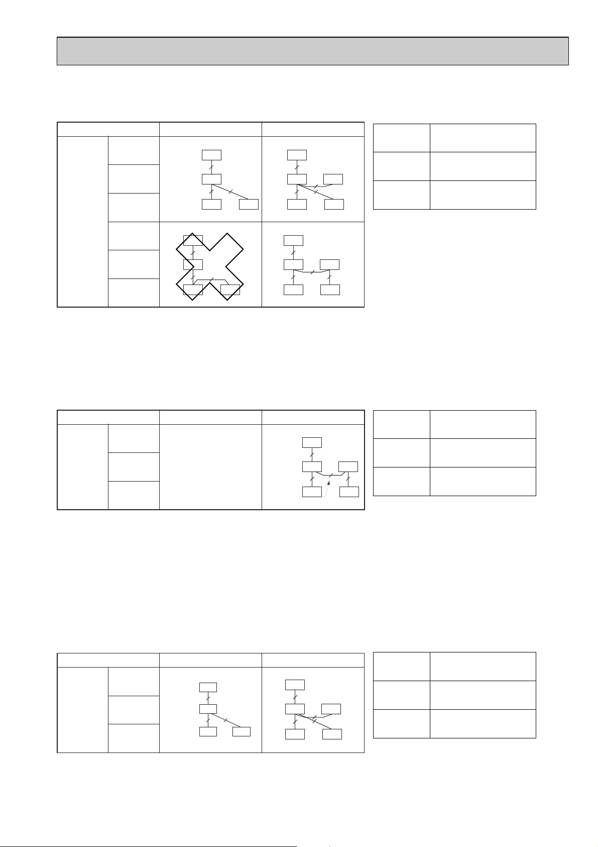
10-3. TWO-REMOTE CONTROLLER OPERATION
g
n
g
m
r
e
(1) Two Wired Remote Controllers
Slim Air Conditioner System
Outdoor unit
OC
Indoor unit IC
Remote
controller
connection
circuit
(Controller
cable)
Wired remote
controller R
Outdoor unit
OC
Indoor unit IC
Wired remote
controller R
[Reference]
1 In the case of free component multi type systems consisting of simultaneous twin units, connect the remote controllers to each indoor unit.
All the functions of the connected indoor units can be controlled even if the system consists of different models. However, some function may be
restricted.
2 In the case of free component multi type systems consisting of simultaneous twin units, the indoor units should be connected by crossover wirin
3 Set one of the remote controllers as the main controller (factory setting) and the other as the sub controller using the remote controller's function
selection.
Standard 1:1 Simultaneous Twin
Indoor/outdoor
connection cable
OC
IC
Remote
controller
cable
R-1
OC
3
IC
2
R-1 R-2
3
2
2
R-2
2
(R: Wired remote controller)
OC
3
IC-1
R-1
OC
3
IC-1
2
R-1
IC-2
2
2
2
R-2
IC-2
2
2
R-2
Indoor controller board switch setting
SW5-3
OFF
ON
Indoor unit IC
IC-1 (Main)
IC-2 (Sub)
(2) Two Wireless Remote Controllers
Slim Air Conditioner System
Standard 1:1 Simultaneous Twin
(R': Wireless remote controller receiver)
Indoor controller board switch setting
SW5-3
Indoor unit IC
Outdoor unit
Remote
controller
receiver
connection
circuit
OC
Indoor unit IC
Wireless remote
controller receiver section R'
Indoor/outdoor
connection cable
—
OC
3
IC-1
Receiver
connection
cable
9 9
R'-1
Remote controller cable
OFF
IC-2
2
ON
R'-2
IC-1 (Main)
IC-2 (Sub)
* Numbers given in ( ) apply when power is supplied to the indoor and outdoor units separately.
[Reference]
1 In the case of free component multi type systems consisting of simultaneous twin units, connect two wireless remote controller receivers
(one each) to any two of the indoor units. All the functions of the connected indoor units can be controlled even if the system consists of differe
models. However, some functions may be restricted.
2 In the case of free component multi type systems consisting of simultaneous twin units, the indoor units should be connected by crossover wirin
In the case of "standard 1:1" connection, it is not possible to connect two remote controller receivers to the indoor units. However, with syste
3
consisting of simultaneous twin units, it is possible to connect a remote controller receiver to two indoor units. In this case, all the pair numbe
will be "0" (factory setting, no change necessary), and all the units will be turned ON/OFF simultaneously.
4 When using two or more wireless remote controllers, the display contents on the remote controllers may differ from the actual settings, since th
operation made last by any of the remote controllers will be effective.
(3) One Wired and One Wireless Remote Controller
(R: Wired remote controller, R': Wireless remote controller receiver)
Slim Air Conditioner System
Standard 1:1 Simultaneous Twin
Indoor controller board switch setting
SW5-3
Indoor unit IC
Outdoor unit
Remote
controller
receiver
connection
circuit
OC
Indoor unit IC
•Wired remote
controller R
Indoor/outdoor
connection cable
Remote
controller
cable
OC
OC
IC-1
3
IC-2
2
9
2
R
R'
3
IC
Receiver
connection
9
2
cable
R
R'
OFF
ON
IC-1 (Main)
IC-2 (Sub)
•Receiver R'
49
Page 50

2.Connecting the remote control interface with each system
(For details on each system, see the relevant instruction manual.)
• Replace the interface unit mounting cord clamp with a supplied mounting cord clamp based on the thickness of the
connecting cable used for each system.
• The cables connected to the Indoor unit should be mounted on or near the Indoor unit.
If the connecting cable is not securely mounted, the connector may detach, break, or malfunction.
• Set the interface dip switch (SW500–502) settings before turning on the power.
• If the interface dip switch (SW500–502) settings are not set correctly, the system will not function properly.
10-4. GROUP CONTROL OPERATION
(COLLECTIVE OPERATION AND CONTROL OF MULTIPLE REFRIGERANT SYSTEMS (2 to 16))
●
●
●
●
Group control can be operated by using MAC-397IF-E.
The setting of wired remote controller is subjected to variation according to the function of the indoor unit.
(for mode operation, setting temperature, fan step, air direction)
The display of remote controller and operating the indoor unit might be different.
Neither the test run nor the function setting can be done by MA remote controller connected with MAC-397IF-E.
1.Connecting the MA& CONTACT TERMINAL Interface to the Indoor Unit
• Connect the interface unit and the indoor control board using the connecting cable that came with the interface.
• Extending or shortening the connecting cable that comes out of the interface may cause it to malfunction. Also,
keep the connecting cable as far as possible away from the electrical wires and ground wire. Do not bundle them together.
Indoor control board
INDOOR
CN105
CN92
or
Connect the connecting cable that comes with the
interface unit to the connector
CN105 or CN92 on the indoor control board.
Mounting screws (black) 3.5 o 12
Interface unit mounting cord clamp or mounting
cord clamps
Connecting cable for each system
Mounting cord clamp
Electrical wire mounting
bracket
Mounting screws 4 o 16
Mounting screws 4 o 10
Mounting cord clamp
50
Page 51

Use as a Wired Remote Control (Using the MA Remote Controller)
Note:
1. Be sure the Auto Heating/Cooling Display Setting on the MA remote controller is set to OFF before use.
• For information on how to set the Auto/Heating Cooling Display Setting, see the MA remote controller
instruction manual.
• The actual operating status of the unit may differ from what is shown on the remote controller display
2. A test run cannot be initiated using the test run switch on the MA remote controller..
3. The horizontal vanes on the unit cannot be operated using the louver switch.
4. The range of room temperature indication is between 10: and 38:.
Indoor unit
Interface unit
CN560
TB580
1
2
A
B
Remote control cord that came with
the MA remote controller (Non polarity)
2
MA remote controller
(PAR-21MAA)
* PAR-20MAA cannot be used
with this interface.
Dip switch settings
SW500 does not have to be set.
SW501:
SW501- No. 1-4: Refrigerant address
• Set this switch when multiple indoor units (and remote control interfaces) are connected to a single MA remote controller.
• Always start the refrigerant address at "0".
Even when connecting multiple outdoor units, set a different refrigerant address for each indoor unit.
Refrigerant
address
0
1
2
15
1
112
3333
4
Refrigerant
address "0"
5
1Outdoor unit
2Outdoor unit
3Indoor unit
4Interface
5MA remote controller
44
Refrigerant
address "1"
Refrigerant
address "2"
ON
1
ON
1
ON
1
ON
1
2 3 4
2 3 4
2 3 4
2 3 4
SW501- No. 5–6
ON
No. 5 should normally be set to OFF.
Under the following conditions, No.6 should normally be set to ON.
6
5
When the model of Mr. SLIM exists in the same group, it sets it to turning ON.
Set them to ON only when using the room temperature sensor installed in the MA remote controller.
* This can be switched when an accurate room temperature cannot be detected by the air conditioner unit.
PKH-GAKL(H) series do not have a room temperature sensor on their MA remote controllers.
51
Page 52

SW501: Settings to accommodate MA remote controller and settings to accommodate outdoor units
SW No.
No. 1
No. 2
No. 3
No. 4
Functions OFF ON Comments
Only specify these settings when connecting an
MA remote controller.
Functions
Room temperature detector
The model of Mr. SLIM exists in the
same group.
This should normally be set to ON.
ON
1
2 3 4 5 6
ON
1
2 3 4 5 6
ON
1
2 3 4 5 6
ON
1
2 3 4 5 6
ON
1
2 3 4 5 6
ON
1
2 3 4 5 6
ON
1
2 3 4 5 6
ON
1
2 3 4 5 6
ON
1
2 3 4 5 6
ON
1
2 3 4 5 6
ON
1
2 3 4 5 6
ON
1
2 3 4 5 6
ON
1
2 3 4 5 6
ON
1
2 3 4 5 6
ON
1
2 3 4 5 6
ON
1
2 3 4 5 6
Refrigerant address 0
Refrigerant address 1
Refrigerant address 2
Refrigerant address 3
Refrigerant address 4
Refrigerant address 5
Refrigerant address 6
Refrigerant address 7
Refrigerant address 8
Refrigerant address 9
Refrigerant address 10
Refrigerant address 11
Refrigerant address 12
Refrigerant address 13
Refrigerant address 14
Refrigerant address 15
OFF
Indoor unit
Not mixed
ON
Remote control
Mixed
Comments
This should normally be set to OFF.
SW No.
No. 5
No. 6
52
Page 53

SW502 : Air Conditioner Function Settings
SW No.
No. 1
No. 2
No. 3
No. 4
Cooling only type/ Heat pump type
Auto mode
Fan speed
Functions
OFF
Heat pump type
Not available
(setting No.3 disabled)
Available
(unit)
4 speeds
ON
Cooling only type
Available
(setting No.3 enabled)
Available
(remote controller)
3 speeds (2-speed
model set ON)
Comments
Set the mode in accordance with the operation
manual for the indoor unit.
Heat pump type : Set to ON.
Cooling only type : Set to OFF.
Set to OFF.
When operating a 2-speed model with the 3-speed
setting (ON), the MA remote controller display will
indicate 3 fan speeds.
The table below shows the displays and the actual
outputs at that time.
Display Meaning Indoor unit output
Low speedLow speed
Medium speed High speed
High speed
High speed
No. 5
Vane
No. 6
Swing
No. 7
Not in use
No. 8
Fan mode
* Fan speed 2 step model : An actual fan speed is 2 step though the display of remote controller becomes 4 step or 3 step.
Available
Available
–
Not available
Not available
Not available
–
Available
The Vane function of either of indoor unit :
When the function is provided, it is Available (OFF).
When the function is not provided, it is Not available (ON).
The Swing function of either of indoor unit :
When the function is provided, it is Available (OFF).
When the function is not provided, it is Not available (ON).
Permanently set to OFF.
Set to ON.
3. Test Run (Check Operations)
Interface status monitor
You can check the status of the interface by the LED lamp on the interface unit board.
LED lamp no.
LED521
LED522
LED523
DC 12 V is not being supplied from the
air conditioner.
Device is not communicating properly
with the air conditioner.
Device is not communicating properly
with the MA remote controller.
Lamp off
Lamp on
DC 12 V is being supplied from the air
conditioner.
–
–
Blinking at approx. 1 second intervals: Device is
communicating normally with the air conditioner.
Blinking at approx. 8 second intervals: Device is communicating normally with the MA remote controller.
* Use the table above to check the device operations.
4. Mounting the Remote Control Interface Unit
Blinking
–
The Interface unit should be placed in a location where the connecting cable from the interface can reach an indoor unit.
The device will not function properly if the connecting cable is extended so the connecting cable should not be extended.
Mount the interface unit securely to a pillar or wall using 2 or more screws.
■ When Using Wall Mounting Brackets
2
1
Attach the wall mounting brackets to the interface unit
Mount the unit to a pillar or wall using 2 mounting screws.
using 2 mounting screws.
Interface unit
Wall mounting
brackets
Mounting screws
Mounting screws
Cord clamp for
wiring
Mounting screws
53
Page 54

■ When Mounting Directly to a Wall
Mount the interface unit case to the wall using the mounting
screws.
Interface case
mounting screws
Mounting
screws
* When mounting the interface unit using a cushioning
material , be sure to mount it in a location where it will not
fall.
Interface unit
Cushioning material
When mounting the interface unit inside a ceiling
or wall, install an access door to facilitate maintenance.
When the interface unit is mounted
above an indoor unit, it should be
positioned 40 mm or more away from the
unit to ensure that ceiling grills can be
removed.
40 mm or more
Attach the interface unit connecting cable here.
Store extra connecting cable in the ductwork space
behind the indoor unit.
* If there is any slack in the connecting cable, use a
fastener to keep it in place.
54
Page 55

10-5. POWER OUTAGE AUTOMATIC RECOVERY OPERATION
Indoor unit Indoor unit Indoor unit
Remote controller
Control room room 1 room 2 room 3
Indoor unit
Relay box Relay box Relay box
Indoor unit
Control circuit
power supply
Indoor unit Indoor unit
Remote
controller
Remote/Local
selection switch
Control room W
room 1 room 2 room 3
Remote
controller
Remote
controller
Remote
controller
• Whenever a power outage or switching of the power supply causes the power supply of an operating air conditioner to go
from OFF to ON, this function will automatically restore the operation of the air conditioner to its previous operating mode.
w If the power is turned from OFF to ON when the air conditioner is not in operation, the air conditioner will not automatically
be turned on. However, the timer operation will be cancelled if the air conditioner is in timer operation (including when the
unit is waiting for its start time). Setting for timer operation must be performed once again.
• If there is a momentary power outage of less than one second while the air conditioner is in operation, there may not be a
clear determination of whether or not there was a power failure. When it has been determined that there has been a power
failure, recovery will take approximately four minutes after the power is restored. Please wait. (Once "PLEASE WAIT" has
appeared on the display, a protection system will operate to prevent the unit from restarting for three minutes.)
When it has been determined that there has been no power failure, operation will continue as is.
• Settings can be made by function selections from the remote controller.
• When there is group control, selection of all refrigerants is required.
10-6. INDIVIDUAL CONTROL OPERATION FROM A SEPARATE ROOM
• By simply centralizing the remote controllers installed in each room in a separate control room, individual control or centralized monitoring of the air conditioners in each room can be attained.
• Air conditioner control can be performed up to a total of 500 meters away by connecting the indoor units and remote controllers with 0.3 to 1.25 mm22-core cable.
• If a remote controller is installed in a room and control room, refer to the section on operating with two remote controllers.
10-7. COMBINED REMOTE/LOCAL CONTROL
• Operation/remote controller prohibit/ stop can be controlled from a remote location by routing the remote stop/start adapter
(PAC-SE55RA-E sold separately) through the relay box installed on site. When this remote control is cancelled, the local
remote controller can be used for operating and stopping the air conditioner.
1. Basic system wiring
• Use the remote start/stop adapter (PAC-SE55RA-E) and connect the "Start/Stop Circuit From Remote Location" that comes
from the relay box and remote/local selection switch and connect it to the CN32 connector on the printed circuit board for
the indoor unit
<Points of precaution>
11
Match the rated power supply voltage of the remote/local selection switch and relay (X2) with the power supply for the con-
troller.
22
When performing group control of multiple outdoor unit using a timer, be sure to arrange the timer so that all units do not start
at the same time. If this is not performed, all of the units will start at one time creating an over current that will cause the circuit
breaker to operate.
33
An on-delay system is one that includes specifications for operating a limited time when an on signal is received and has a tem-
porary off timer for recovery operations.
44
Use a connecting relay when the wiring length exceeds 10 meters, such as when performing remote wiring. If this is not pro-
vided, abnormal operation will occur.
(1) System diagram
W The AC for the control room is usually disconnected from the remote/local control system.
55
Page 56

Control circuit
power supply
Dedicated short
circuit prevention
device
Remote/Local
selection switch
No.1 unit
relay box
No.2 unit
relay box
3 Relay box
2
Adapter for
remote start/stop
1
Remote/Local
selection switch
T Timer
(On delay system)
X Relay
Model
PAC-SE55RA-E
(Sold separately)
(Example)
Single polarity
single-throw switch
(125V rating)
To
next
unit
T
Brown
Red
X
2 X2
T
One method of easily
distinguishing the on/off
status of SW1 and SW2
is to use together with a
"illuminated switch R" or
pilot lamp.
T
X
2
SW1
SW2
T
X
2
Orange Orange
Brown
Red
•
Starting/stopping
with remote
controller disabled.
• Starting/stopping by
remote operation
enabled.
•
Starting/stopping
with remote
controller disabled.
• AC is in operation.
• Starting/stopping by
remote operation
enabled.
•
Starting/stopping
with remote
controller disabled.
• Starting/stopping by
remote operation
enabled.
•
Starting/stopping
with remote
controller disabled.
• AC is in operation.
• Starting/stopping by
remote operation
enabled.
Remote
control
OFFON
Description of
functions
OFFON
SW1
SW2
OFFON
Remote/Local
selection switch
(2) Basic wiring diagram
Indoor unit
circuit board
CN32
Orange
Red
Brown
On site wiring On site wiring
On site wiring
Timer
Timer
For remote operation
On site wiring
On site wiring
This is not used.
Protect exposed wire by
wrapping with insulating tape
On site wiring
SW1
Indoor unit
circuit board
CN32
Orange
Red
Brown
SW1
SW2
Indoor unit
circuit board
CN32
Orange
Red
Brown
SW2
Indoor unit
circuit board
CN32
Orange
Red
Brown
SW2
Indoor unit
circuit board
CN32
Orange
Red
Brown
Indoor unit
circuit board
CN32
Orange
Red
Brown
SW2
For remote operation
For timer operation
(3) Part specifications
Note: When using group address, connect to refrigerant
address "0" on the inside.
2. Examples of system applications
In any of the following examples, there is a five to six second delay from the time the operating command is issued until the
operation begins.
11
This is when starting and stopping is performed by remote operation or external timer and when starting and stopping by
the remote controller is to be prohibited.
22
This is when starting and stopping is performed by remote operation or external timer and when starting and stopping by
the remote controller is to be separated.
33
This is when starting and stopping is performed by remote operation and then allowing starting or stopping by remote con-
trol at any time.
44
This is when permitting or prohibiting operation by remote controller is performed by external circuit.
Use momentary switch for SW2. (Manual operation/automatic recover switch on
time is more than one second.)
Press SW2 (on time is more than one second) and operation starts. After this has
been done, stopping or restarting can be down by remote controller.
If SW2 is on, operation by remote controller cannot be
performed.
If SW2 is off, operation by remote controller is permitted.
56
Page 57

10-8. OBTAINING REMOTE DISPLAY
CN90 CN1
CN41
Wireless
3
TB3
External input
TB2
Error
TB1
Operation
2
Indoor control circuit board Remote operation adapter
5
External input
Error output
(No voltage momentary "a" contact)
Operating output
(No voltage momentary "a" contact)
No voltage
(Momentary "a" contact)
HA
Power supply for controller
Timer control
panel (on-site)
Remote controller
Indoor unit
Remote controller
Indoor unit
Remote controller
Indoor unit
Use the remote operation adapter (PAC-SF40RM-E) to provide operation/error non-voltage contact output and on/off input
function.
(1) Wiring method
..
Caution
TB3 is a dedicated terminal for contact point input. Never input voltage. It will damage
the indoor control circuit board.
<Connections on the indoor unit side>
11
When using external output function
Insert the 9-prong connector (3-core) of the attached cable to CN90 on the indoor control circuit board.
22
When using the external input function
Insert the 4-prong connector (2-core) of the attached cable to CN41 on the indoor control circuit board.
W The connector is direction-sensitive. Use care not to make an error when inserting.
Never force the connectors. This will result in damage.
(2) Locally procured parts
Item Name Model and specifications
External output function External output signal wire Use sheathed vinyl coated cord or cable.
Wire type: CV, CVS or equivalent.
Wire size: Stranded wire 0.5mm
2
to 1.25mm
Single straged: {0.65mm to 1.25mm
Display lamp, etc. No voltage “a” contact AC200V (DC30V), 1A or less
External input function External input signal wire Use sheathed vinyl coated cord or cable.
Wire type: CV, CVS or equivalent.
Wire size: Stranded wire 0.5mm2to 1.25mm
Single straged: {0.65mm to 1.2mm
Switch No voltage “a” contact
(Start and stop operation is switched by inputting a
pulse of 200ms or more)
2
2
10-9. TIMER OPERATION
● Timer operation can be performed by setting the wired or wireless remote controller timer. Start and stop times can be set in
10-minute increments within a 24-hour period.
● When used in combination with the central control remote controller of the M-NET control system for the outdoor unit, one
program timer can be used for individual timer settings for each group of the central control system. (Each timer setting can
be stored in data memory so timer settings for up to 50 groups can be set individually.)
W Please refer to the MELANS catalog or technical information for details about the central control remote controller.
1.Operating with on-site timer
(1) Summary of system
If the “Remote ON/OFF adapter” (PACSE55RA-E) (sold separately) is used, the
on-site timer can be operated to turn each
unit on and off.
57
Page 58

(2) Basic pattern for timer control
Orange
As selected by remote controller operation switch.
From indoor unit
Red
Brown
T
SW ON
SW OFF
Timer control
Remote controller control
SW
Orange
From indoor unit
Red
Brown
T
Wiring diagram
Control circuit board
Slim indoor unit
Lossnay
Lossnay linkage
(PAC-SB81VS)
External control
input terminal
block
1
2
3
Connector
(CN2L)
Basic wiring
X: Relay
(DC12V) CN25 (Indoor unit circuit board)
System example
Remote controller
Indoor unit
Relay box
(On-site tinstallation)
Relay box
(On-site tinstallation)
Remote controller
Humidifier unit
Humidifier
unit
Use a no-voltage contact point output timer (one that has separate circuits for the load side and timer power supply).
a) Timer-independent control b) Combined control by timer and remote controller
(3) Basic system
Refer to 10-7. COMBINED REMOTE/LOCAL CONTROL.
10-10. LINKED OPERATION WITH PERIPHERAL AIR CONDITIONERS EQUIPMENT
■ Lossnay operation
● Linked operation with a Lossnay unit can be obtained by connecting Lossnay linkage cable (Model PAC-SB81VS - sold
separately) to the CN2L (Remote kit) on the circuit board of the indoor unit. This function must be selected from the
remote controller.
11
Summary of wiring
● Connect the Lossnay linkage cable (Model PACSB81VS) connector to CN2L on the indoor unit on the
circuit board of the indoor unit.
● Connect the lead wire of the Lossnay linkage cable to
the Lossnay external control input terminal blocks (1)
and (2)
(At this time, the input terminal blocks (1) and (2)
have no polarity.)
22
Precautions when wiring
● The Lossnay linkage cable can be extended up to a maximum of 500 meters.
When extending the Lossnay linkage cable, be sure to connect securely and take proper steps to ensure insulation.
(Extension cable specifications: Sheathed vinyl cord or cable 0.5 to 0.75mm
● Lossnay linked cable
● Arrange wiring so that there can be no contact between the Lossnay linkage cable and the power supply cord. Contact
may cause malfunctioning. (Separate by 5cm or more.)
2
)
10-11. OBTAINING HUMIDIFIER SIGNAL
● The humidifier signal that is linked to the AC heating operation (indoor unit ventilator) can be obtained by connecting the
adapter for the humidifier signal to connector CN25 on the printed circuit for the indoor unit and wiring it to the humidifier
unit via the on-site relay box. There is no output when the thermostat is off, during heating preparation and during
defrosting.
W Please consult your nearest Mitsubishi Electric
representative for information about obtaining the
adapter for humidifier signal.
10-12. EXTERNAL MOUNTING OF TEMPERATURE SENSOR
● Temperature control from an alternative external location can be performed by connecting the temperature sensor (Model
PAC-SE41TS-E - sold separately) to the CN20 connector on the circuit board for the indoor unit.
● The wired remote controller also has an internal temperature sensor. Function selection from the remote controller is
required.
Refer to “FUNCTION SETTING” for information of installation manual about selecting functions with the remote controller.
58
Page 59

10-13. MULTIPLE REMOTE CONTROL DISPLAY
CN51
connector(5P)
GREEN
Power
supply
Electrical insulation is needed.
Wiring at the actual place
Optional multiple display
adapter
The maximum distance between
indoor board and relay is 10m.
YELLOW
ORANGE
RED
BROWN
5
X2
X2
GL
RL
X1
X1
1
<Wiring >
Power
supply
Remote
controller
cable
Relay box
(Field supply)
Remote
controller
Remote
controller
Remote
controller
3wires
3wires
3wires
2wires
No.1 unit No.2 unit No.3 unit
Muitiple remote control
ON-OFF display
(Field supply)
(Operation check)
<System>
Power
supply
RL-1
GL-1
Multiple Remote Control Display
Multiple remote
controller adapter
connect to
the connector CN51
Relay box
5
X1-1
X2-1
1
<Wiring diagram>
RL-2
GL-2
RL-3
No.1 unit
GL-3
X1-1
X2-1
X1-2
X1-3
X2-3
X2-2
5
1
No.2 unit
5
1
No.3 unit
X1-2
X2-2
X1-3
X2-3
Be sure to secure insulation
material by tape and such
5
Green
Yellow
Orange
Connector (5P)
Package side
Multiple remote
controller adapter
PAC-SA88HA-E
Be sure to secure insulation
material by tape and such
Installation at site
CN51
on
indoor
controller
board
Red
Brown
1
~
MB
You can control several units with a multiple remote control display, by
wiring an optional multiple display adapter (PAC-SA88HA-E) with relays
and lamps on the market.
How to wire
(1) Connect the multiple display adapter to the connector CN51 on the
indoor controller board.
(2) Wire three of the five wires from the multiple display adapter as shown
in the figure below.
[Notes on Signs]
X1:Relay (for operation lamp)
X2:Relay (for check lamp)
RL:Operation Lamp
GL:Check Lamp
[Field supplied parts]
Relays:12V DC with rated coil power
consumption below 0.9W.
Lamps:Matching to power supply voltage.
10-14. INTERLOCKING OPERATION METHOD WITH DUCT FAN (Booster fan)
●Whenever the indoor unit is operating,
the duct fan operates.
(1)Connect the optional multiple remote
controller adapter(PAC-SA88HA-E)to
the connector CN51 on the indoor
controller board.
(2)Drive the relay after connecting the
12V DC relay between the Yellow and
Orange connector lines.
Use a relay under 1W.
MB: Electromagnetic switch power relay
for duct fan.
X: Auxiliary relay (12V DC LY-1F)
59
Page 60
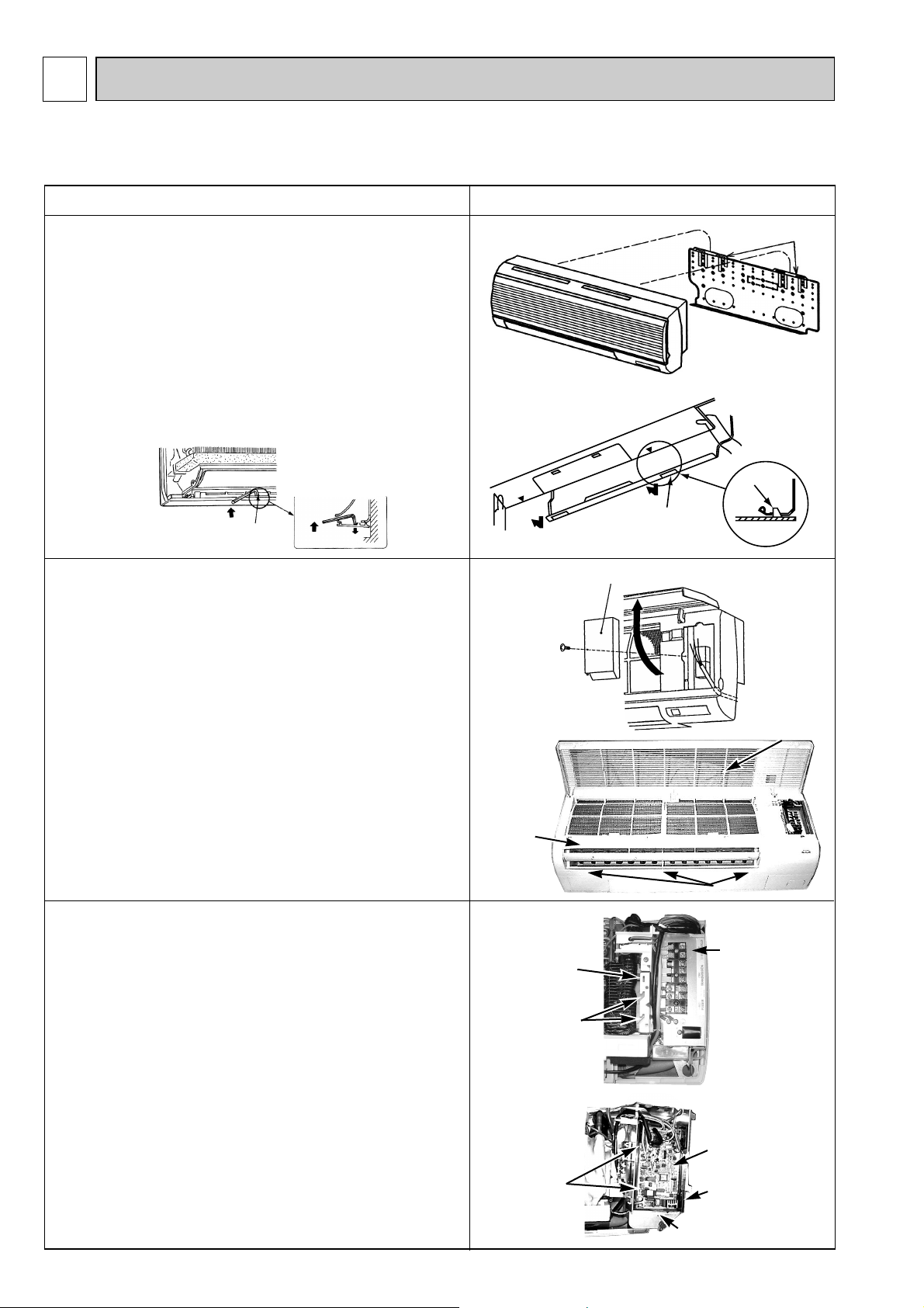
11
DISASSEMBLY PROCEDURE
PKH-1.6GAKL PKH-2GAKL
PKH-1.6GAKLH PKH-2GAKLH
OPERATION PROCEDURE
1. REMOVE THE LOWER SIDE OF THE INDOOR UNIT FROM
THE INSTALLATION PLATE.
(1) Remove the left / right corner box of the indoor unit.
(2) Hold and pull down the lower and both ends of the indoor
unit, and remove the ▼ section from the square hole.
(Refer to the figure 2.1)
Or remove the front panel and push the ▼ section down
by using hexagonal wrench, etc. from the front side.
(Refer to the figure 2.2).
(3) Unhook the top of the indoor unit from the back plate catch.
(Figure 2.2)
Square hole
2. REMOVING THE FRONT PANEL.
(1) Open the front grille.
(2) Remove the terminal block cover with a screw.
(3) Remove the screw 3 caps then remove the set 3 screws.
(4) After removing the lower side of the front panel a little,
remove it as pulling toward upper.
Up
Down
PHOTOS & ILLUSTRATION
(Figure 1)
(Figure 2.1)
(Figure 3)
Hook
Hook
Square hole
Terminal block cover
3. REMOVING THE INDOOR CONTROLLER BOARD.
(1) Remove the terminal block cover.
(2) Remove the front panel. (see the photo 1)
(3) Remove the electrical box(2 screws).
(4) Remove the electrical box cover(1 screw).
(5) Disconnect the connector on the controller board and
remove the controller board by Pulling up the hook of the
controller case.
w To smooth works, hang the side hooks of the electrical
parts box on the hook of the motor cover.
(see the photo 3)
(Photo 1)
Front
panel
(Photo 2)
Motor cover
Hooks for
Electrical parts
box w
(Photo 3)
Front grille
Set screws
Electrical parts
box
Control board
60
Hook
Controller case
Electrical box
Page 61
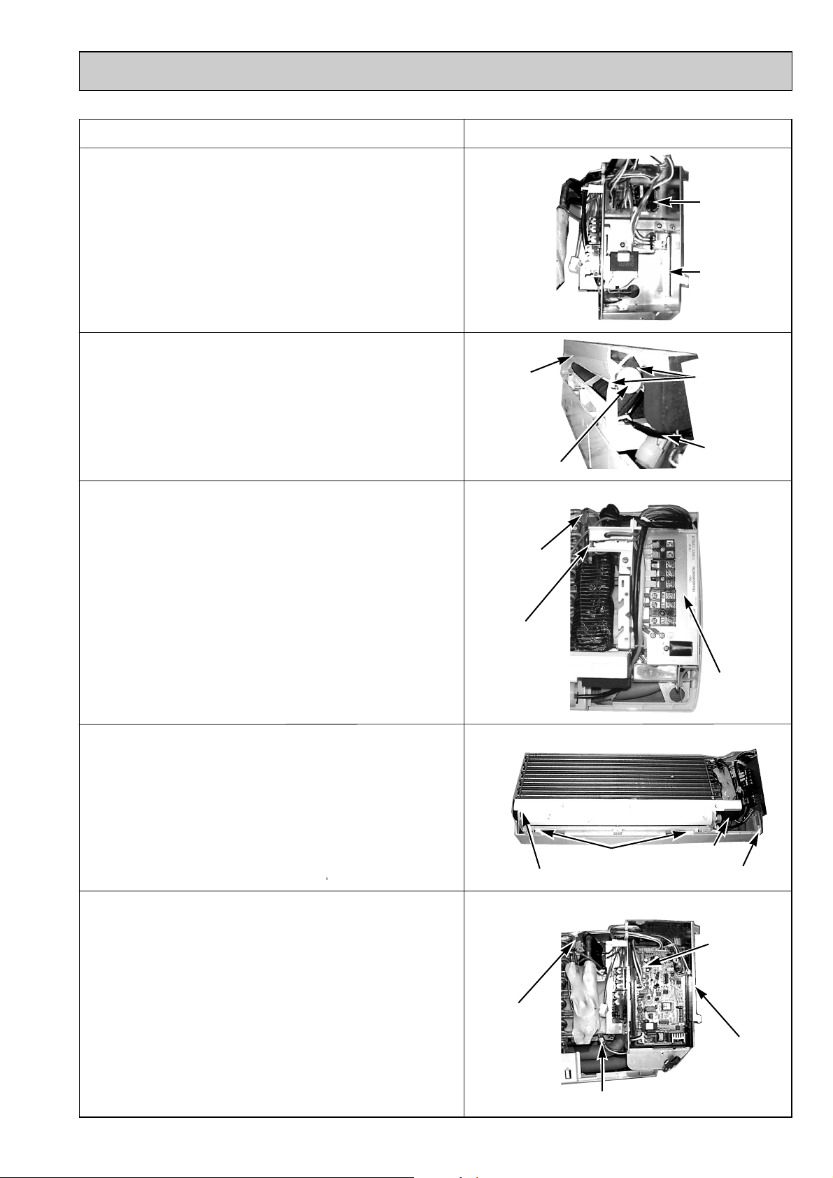
OPERATION PROCEDURE
PHOTOS & ILLUSTRATION
4. REMOVING THE POWER BOARD
(1) Remove the front panel.(see the photo 1)
(2) Remove the electrical box(2screws).(see the photo 2)
(3) Disconnect the whole connector in the control board.
(4) After lifting the controller case with pressing it’s convex
section, remove the controller case and the control board
simultaneously.(see the photo 3)
(5) Disconnect the connector in the power board.
(6) Remove the power board.
5. REMOVING THE VANE MOTOR
(1) Disconnect the connector CN6V on the indoor controller
board.
(2) Remove the 2screws of the vane motor, disconnect the
lead wire and remove the vane motor from the shaft.
6. REMOVING THE THERMISTOR
(1) Removing the room temperature thermistor TH1.
1Disconnect the connector CN20<red> on the indoor
controller board.
2Remove the room temperature thermistor from the holder.
(2) Removing the pipe temperature thermistor TH2.
1Disconnect the connector CN21<white> on the controller
board.
2Remove the pipe temperature thermistor with set to the pipe.
(Photo 4)
(Photo 5)
Nozzle
assemble
Van motor
(Photo 6)
Pipe
temperature
thermistor
Room
temperature
thermistor
Power board
Electrical box
Set screws
Lead wire
7. REMOVING THE NOZZLE ASSEMBLE
(1) Disconnect the connector CN6V on the controller board.
(2) Disconnect the lead wire of the vane motor.
(3) Remove the corner cover.
(4) Pull the drain hose out from the nozzle assemble.
(5) Unhook the hook of the lower nozzle assemble and
pull the nozzle assemble toward you, then remove the
nozzle assemble by sliding it down.
8. REMOVING THE ELECTRICAL BOX
(1) Remove the terminal block cover.
(2) Remove the front panel.(see the photo 1)
(3) Disconnect the vane motor connector.
(4) Disconnect the fan motor connector from the fan motor.
(5) Remove the pipe temperature thermistor.(see the photo 6)
(6) Remove the electrical parts box (2screws).
(Photo 7)
Nozzle assemble
(Photo 8)
Pipe
temperature
thermistor
Hook
Electrical
parts box
Drain hose
Corner cover
Vane motor
connector
Electrical box
61
Fan motor connector
Page 62

OPERATION PROCEDURE PHOTOS & ILLUSTRATION
9. REMOVING THE FAN MOTOR.
(1) Remove the terminal block cover.
(2) Remove the front panel.(see the photo 1)
(3) Remove the electrical box.(see the photo 8)
(4) Remove the nozzle assemble.(see the photo 7)
(5) Remove the fan motor leg fixing 3 screws.
(6) Unscrew the set screws using by alankey and remove it by
sliding the fan motor to right.
(7) Remove the 4 screws and remove the motor cover from the
fan motor leg.
10. REMOVING THE LINE FLOW FAN
(1) Remove the terminal block cover.
(2) Remove the front panel.(see the photo 1)
(3) Remove the electrical box.(see the photo 8)
(4) Remove the nozzle assembly.(see the photo 7)
(5) Remove the fan motor.(see the photo 9)
(6) Remove the pipe fixture with 2 screws.(see the photo12)
(7) Remove the left / right screws of the heat exchanger and
pull the left-hand side up.
(8) Remove the 2 screws by sliding it toward you remove the
fixture(fixing bearing).
w The fan motor is removable first, when the fan
removing is hard.
w When resetting the fan to the fan motor.
Locate and fix the shaft after installing the fan.
(Photo 9)
Set
screw
(Photo 10)
Motor cover
Fan motor
(Photo11)
Heat exchanger
Set screws
Fixture(fixing bearing)
Motor cover
Fan motor
screws
motor leg
11. REMOVING THE HEAT EXCHANGER
(1) Remove the terminal block cover.
(2) Remove the front panel.(see the photo 1)
(3) Remove the electrical box.(see the photo 8)
(4) Remove the corner box.
(5) Remove the nozzle assemble.(see the photo 7)
(6) Remove the 2 screws and the pipe fixture.
(7) Remove the 2 screws and heat exchanger.
12. REMOVING ELECTRICAL HEATER (PKH-1.6/2GKLH only)
(1) Remove the terminal block cover.
(2) Disconnect the connector <yellow> for the wireless remote
controller.
(3) Remove the front panel.(see the photo 1)
(4) Remove the electrical box.(see the photo 8)
(5) Remove the nozzle assembly.(see the photo 7)
(6) Remove the heat exchanger.(see the photo 12)
(7) Remove the 2 screws and electrical heater.
(Photo 12)
Set screw
(Photo 13)
Pipe fixture
Set screws
Electrical heater
Heat exchanger
Set screws
62
Page 63

OPERATION PROCEDURE
PHOTOS & ILLUSTRATION
13. REMOVING the SIGNAL RECEIVING P.C. BOARD
(1) Remove the terminal block cover.
(2) Disconnect the connector <yellow> for the wireless remote
controller.
(3) Remove the front panel.(see the photo 1)
(4) Remove the 2 screws and signal receiving p.c. board cover.
(5) Remove the signal receiving p.c. board.
(Photo 14)
Set screws
(Photo 15)
Front
panel
Signal receiving p.c. board cover
Front
panel
Signal receiving p.c. board
63
Page 64

T7W E68 480
R01 16Y 480
R01 09Y 114
R01 07Y 114
R01 07Y 102
R01 005 103
R01 07Y 106
T7W A00 675
R01 07Y 524
R01 07Y 527
R01 07Y 530
R01 09Y 038
R01 07Y 038
R01 07Y 059
R01 E04 223
R01 E03 317
R01 07Y 135
R01 07Y 105
T7W A01 762
No.
Parts No. Parts Name
Specifications
Remarks
(Drawing No.)
Wiring
Diagram
Symbo
l
Recommended
Q'ty
Unit
Amount
Q'ty/ set
PKH-•GAKLH
PKH-•GAKL
1.6 1.6 22
Price
1
2
3
4
5
6
7
8
9
10
11
12
13
14
15
16
17
HEAT EXCHANGER
HEAT EXCHANGER
LINE FLOW FAN
LINE FLOW FAN
BEARING MOUNT
SLEEVE BEARING
BEARING SUPPORT
FAN GUARD
DRAIN PLUG
DRAIN HOSE
NOZZLE
GUIDE VANE
GUIDE VANE
ARM
VANE MOTOR
WIRERLESS ADAPTER CONTROLLER BOARD
MOTOR COVER
RUBBER MOUNT
FAN MOTOR
MV
W.B
MF
1
1
1
1
1
1
1
1
1
4
10
2
1
1
1
2
1
1
1
1
1
1
1
1
1
1
4
10
2
1
1
1
2
1
1
1
1
1
1
1
1
1
1
4
10
2
1
1
1
2
1
1
1
1
1
1
1
1
1
1
4
10
2
1
1
1
2
1
PM4V30-K
12 PARTS LIST
ELECTRICAL PARTS
PKH-1.6GAKL PKH-2GAKL
PKH-1.6GAKLH PKH-2GAKLH
1
4
3
5
2
37
36
35
6
9
10
12
11
34
32
28
33
7
8
17
1
31
30
29
27
26
25
24
16
10
13
14
15
64
18
22
19
21
20
To be continued on the next page.
23
Page 65

—
T7W A14 716
T7W E27 716
T7W 512 716
R01 588 255
T7W E47 310
—
—
T7W E24 313
R01 E02 239
—
R01 71G 215
—
T7W E05 202
R01 E02 202
R01 07Y 130
R01 E00 418
R01 64K 700
T7W E13 300
R01 986 706
R01 20J 303
No.
Parts No. Parts Name
Specifications
Remarks
(Drawing No.)
Wiring
Diagram
Symbo
l
Recommended
Q'ty
Unit
Amount
Price
18
19
20
21
22
23
24
25
26
27
28
29
30
31
32
33
34
35
36
37
38
TERMINAL COVER
TERMINAL BLOCK
TERMINAL BLOCK
TERMINAL BLOCK
CAPACITOR
INDOOR CONTROLLER BOARD
CONTROLLER COVER
CONTROLLER CASE
POWER BOARD
FUSE
ELECTRICAL PARTS COVER
HEATER CONTACTOR
SENSOR HOLDER
ROOM TEMPERATURE THERMISTOR
PIPE TEMPERATUER THERMISTOR
MOTOR SUPPORT
RESTRICTOR VALVE
HEATER THERMAL SWITCH
HEATER ELEMENT
THERMAL FUSE
INSULATOR
(BG02V195H10)
(BG02V194G01)
(BG25J080H02)
(BG00V196G47)
(RG25C546H06)
3P(1, 2, 3)
2P(1,2)
2.0= ✕440V
250V 6.3A
60-C OFF 45-C ON
800W
104-C 10A
TB2
TB4
TB5
C
I.B
P.B
FUSE
88H
TH1
TH2
26H
H1
FS1
3P(L, N, ;)
1
1
1
1
1
1
1
1
1
1
1
1
1
1
1
1
1
1
1
1
1
1
1
1
1
1
1
1
1
1
1
1
1
1
1
1
1
1
1
1
1
1
1
1
1
1
1
1
1
1
1
1
1
1
1
1
1
1
1
1
1
1
1
1
1
1
1
1
1
1
1
1
1
1
Q'ty/ set
PKH-•GAKLH
PKH-•GAKL
1.6 1.6 22
From the preceding page.
Part numbers that is circled is not shown in the figure.
65
Page 66

STRUCTURAL PARTS
1
2
3
4
5
6
7
8
9
10
11
12
13
14
15
BACK PLATE
CORNER COVER
UNDER COVER
FRONT PANEL
SCREW CAP
VANE SLEEVE
FRONT GRILLE
AIR FILTER
AUTO VANE
RECEIVING UNIT
CORNER COVER
BOX ASSEMBLY
BOX ASSEMBLY
WIRELESS REMOTE CONTROLLER
WIRELESS REMOTE CONTROLLER DOOR
WIRELESS REMOTE CONTROLLER HOLDER
1
1
1
1
3
1
1
2
1
1
1
1
1
1
1
1
1
1
1
3
1
1
2
1
1
1
1
1
1
1
1
1
1
1
3
1
1
2
1
1
1
1
1
1
1
1
1
1
1
3
1
1
2
1
1
1
1
1
1
1
No.
Parts No.
Parts Name
Specifications
Remarks
(Drawing No.)
Wiring
Diagram
Symbol
Recom-
mended
Q'ty
Unit
Amount
Price
R01 07Y 808
R01 09Y 658
R01 07Y 623
R01 89Y 651
R01 07Y 096
R01 07Y 092
R01 07Y 691
R01 A16 500
R01 07Y 002
R01 24K 658
R01 07Y 658
R01 09Y 635
R01 07Y 635
T7W E06 714
R01 E01 049
R01 E00 075
RU
Q'ty/ set
PKH-•GAKLH
PKH-•GAKL
1.6 1.6 22
PKH-1.6GAKL PKH-2GAKL
PKH-1.6GAKLH PKH-2GAKLH
2
4
5
6
1
3
12
11
7
8
9
10
13
14 15
66
Page 67

13
1
2
3
4
5
BRN
RED
ORN
YLW
GRN
OPTIONAL PARTS
13-1. REFRIGERANT PIPES
Service Ref. : PKH-1.6GAKL(H) PKH-2GAKL(H)
Part No. PAC-05FFS-E PAC-07FFS-E PAC-10FFS-E PAC-15FFS-E
Pipe length 5m 7m 10m 15m
Pipe size O.D .
Connection method Indoor unit: Flared Outdoor unit: Flared
Note 1. How to connect refrigerant pipes.
Factory supplied optional refrigerant pipings contain refrigerant at the above atmospheric pressures. As long as the
connection takes no more than 5 minutes, no air will enter, and there will be no need for air purging.
Remove the blind caps and make the connections within 5 minutes. After the connections for the indoor and outdoor
units are made, open the stop valve on the outdoor unit to allow refrigerant gas to flow.
Note 2. The following main parts are contained in the optional refrigerant piping kit.
Heat insulating cover, vinyl tapes, nipples, sleeve and flange (for wall hole).
Liquid:[9.52 Gas:[15.88
13-2. MULTIPLE REMOTE CONTROLLER ADAPTER
This adapter is needed for remote indication (operation/check).
Part No.
Applicable Service Ref.
PAC-SA88HA-E
PKH-1.6, 2GAKL(H)
13-3. REMOTE ON/OFF ADAPTER
Part No.
Applicable Service Ref.
13-4. REMOTE SENSOR
Part No.
Applicable Service Ref.
13-5. REMOTE OPERATION ADAPTER
Part No.
Applicable Service Ref.
13-6. WIRED REMOTE CONTROLLER
Part No.
Applicable Service Ref.
PAC-SE55RA-E
PKH-1.6, 2GAKL(H)
PAC-SE41TS-E
PKH-1.6, 2GAKL(H)
PAC-SF40RM-E
PKH-1.6, 2GAKL(H)
PAR-21MAA
PKH-1.6, 2GAKL(H)
67
Page 68

TM
HEAD OFFICE : TOKYO BLDG., 2-7-3, MARUNOUCHI, CHIYODA-KU, TOKYO 100-8310, JAPAN
CCopyright 2006 MITSUBISHI ELECTRIC ENGINEERING CO., LTD.
Distributed in Apr. 2006 No.OC383 PDF 9
Made in Japan.
New publication, effective Apr. 2006
Specifications subject to change without notice.
 Loading...