

Mitsubishi PKFY-P63VKM-E.TH, PKFY-P100VKM-ER1.TH, PKFY-P63VKM-ER1.TH, PKFY-P100VKM-E.TH Service Manual
TECHNICAL & SERVICE MANUAL
CONTENTS
1. TECHNICAL CHANGES
.........................
2
2. SAFETY PRECAUTION
..........................
2
3. PART NAMES AND FUNCTIONS
..........
6
4. SPECIFICATION
...................................
14
5. OUTLINES AND DIMENSIONS
............
16
6. WIRING DIAGRAM
...............................
17
7. REFRIGERANT SYSTEM DIAGRAM
........
19
8. TROUBLESHOOTING
..........................
19
9. DISASSEMBLY PROCEDURE
.............
27
Indoor unit
[Model names] [Service Ref.]
PKFY-P63VKM-E.TH
PKFY-P63VKM-ER1.TH
PKFY-P100VKM-E.TH
PKFY-P100VKM-ER1.TH
No. OCH447
REVISED EDITION-B
INDOOR UNIT
SPLIT-TYPE, HEAT PUMP AIR CONDITIONERS
Note:
•
This manual describes only
service data of the indoor
units.
• RoHS compliant products
have <G> mark on the spec
name plate.
December 2012
PARTS CATALOG (OCB447)
Revision:
• PKFY-P63/100VKM-ER1.TH
have been added in
REVISED EDITION-B.
• Some descriptions have
been modified.
• Please void OCH447
REVISED EDITION-A.
PKFY-P63VKM-E
PKFY-P100VKM-E
R407C R22R410A
2
2
SAFETY PRECAUTION
CAUTIONS RELATED TO NEW REFRIGERANT
1
TECHNICAL CHANGES
PKFY-P63VKM-E.TH PKFY-P63VKM-ER1.TH
PKFY-P100VKM-E.TH PKFY-P100VKM-ER1.TH
• INDOOR CONTROLLER BOARD (I.B.) has been changed. (S/W version up)
Cautions for units utilizing refrigerant R407C
Do not use the existing refrigerant piping.
The old refrigerant and lubricant in the existing piping
contain a large amount of chlorine which may cause the
lubricant deterioration of the new unit.
Use “low residual oil piping”
If there is a large amount of residual oil (hydraulic oil, etc.)
inside the piping and joints, deterioration of the lubricant
will result.
Use ESTR , ETHER or HAB as the lubricant to
coat flares and flange connection parts.
If large amount of mineral oil enters, that can cause
deterioration of refrigerant oil etc.
Use liquid refrigerant to charge the system.
If gas refrigerant is used to seal the system, the composition
of the refrigerant in the cylinder will change and performance
may drop.
Do not use a refrigerant other than R407C.
If another refrigerant (R22, etc.) is used, the chlorine in the
refrigerant may cause the lubricant deterioration.
Use a vacuum pump with a reverse flow check valve.
The vacuum pump oil may flow back into the refrigerant
cycle and cause the lubricant deterioration.
If dust, dirt, or water enters the refrigerant cycle,
deterioration of the oil and compressor trouble may result.
Store the piping indoors, and both ends of the
piping sealed until just before brazing.
(Leave elbow joints, etc. in their packaging.)
Ventilate the room if refrigerant leaks during
operation. If refrigerant comes into contact with
a flame, poisonous gases will be released.
Never use any refrigerant other than that specified.
Doing so may cause a burst, an explosion, or fire when the
unit is being used, serviced, or disposed of.
Correct refrigerant is specified in the manuals and on the
spec labels provided with our products.
We will not be held responsible for mechanical failure,
system malfunction, unit breakdown or accidents caused
by failure to follow the instructions.
Use the specified refrigerant only.
OCH447B
33
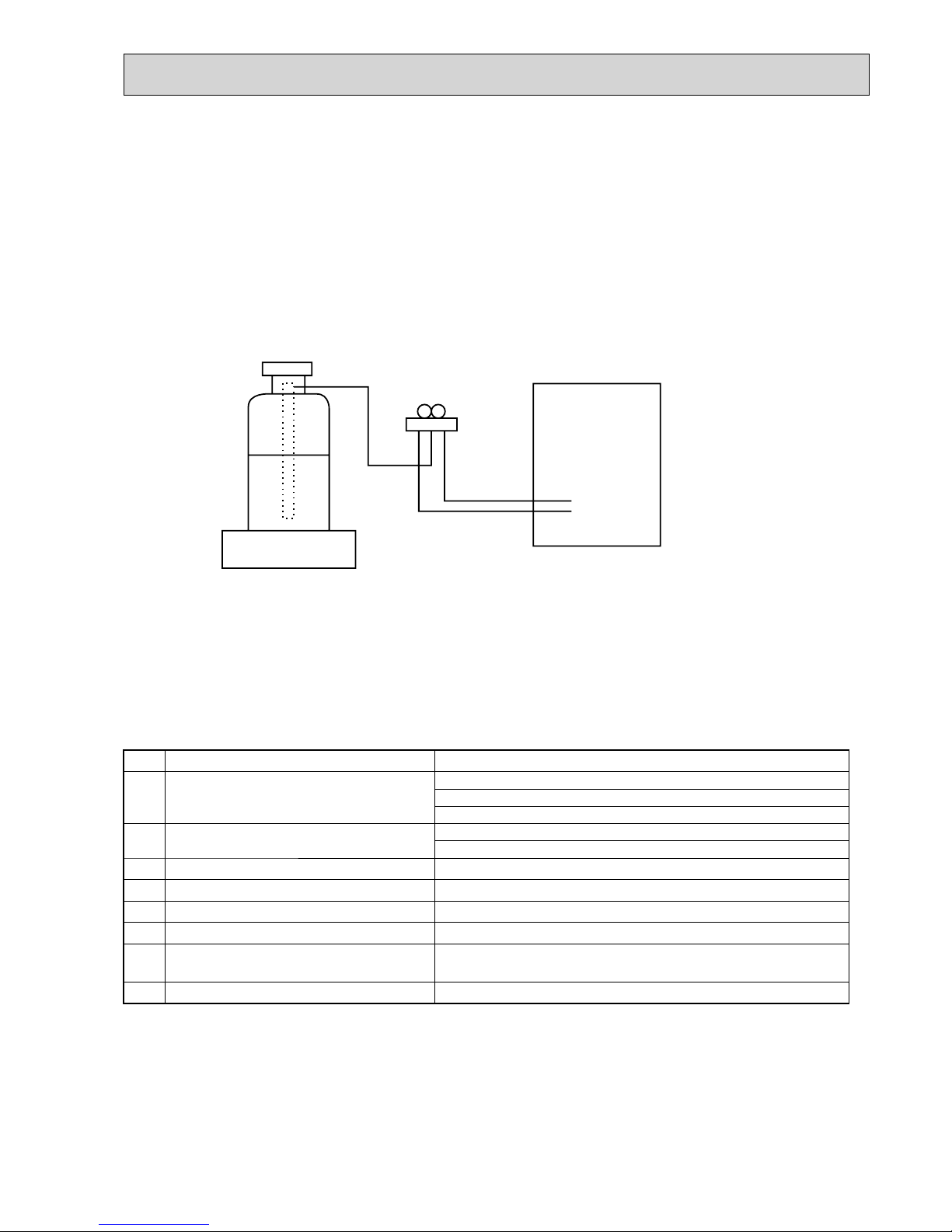
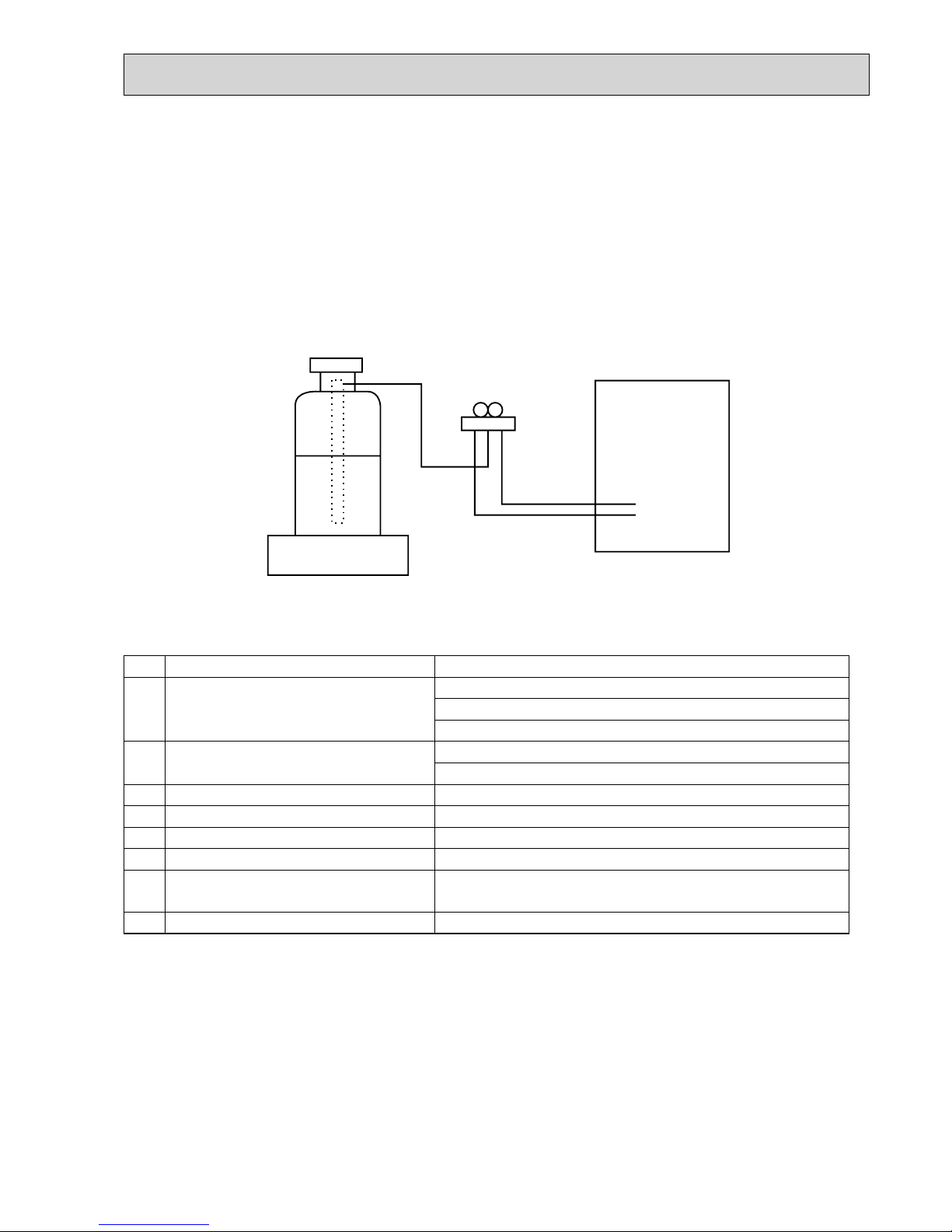
[3] Service tools
Use the below service tools as exclusive tools for R407C refrigerant.
[2] Refrigerant recharging
(1) Refrigerant recharging process
1Direct charging from the cylinder.
· R407C cylinder available on the market has a syphon pipe.
· Leave the syphon pipe cylinder standing and recharge it.
(By liquid refrigerant)
(2) Recharge in refrigerant leakage case
· After recovering the all refrigerant in the unit, proceed to working.
· Do not release the refrigerant in the air.
· After completing the repair service, recharge the cycle with the specified amount of liquid refrigerant.
Gravimeter
Unit
[1] Cautions for service
· After recovering the all refrigerant in the unit, proceed to working.
· Do not release refrigerant in the air.
· After completing the repair service, recharge the cycle with the specified amount of liquid refrigerant.
No.
Tool name Specifications
1
Gauge manifold
· Only for R407C
· Use the existing fitting
SPECIFICATIONS
. (UNF7/16)
· Use high-tension side pressure of 3.43MPa·G or over.
2
Charge hose
· Only for R407C
· Use pressure performance of 5.10MPa·G or over.
3
Electronic scale
—
4
Gas leak detector
· Use the detector for R134a or R407C.
5
Adaptor for reverse flow check
· Attach on vacuum pump.
6
Refrigerant charge base
—
7
Refrigerant cylinder
· For R407C · Top of cylinder (Brown)
· Cylinder with syphon
8
Refrigerant recovery equipment
—
OCH447B
4
Cautions for units utilizing refrigerant R410A
Charge refrigerant from liquid phase of gas
cylinder.
If the refrigerant is charged from gas phase, composition
change may occur in refrigerant and the efficiency will be
lowered.
Do not use refrigerant other than R410A.
If other refrigerant (R22 etc.) is used, chlorine in refrigerant can cause deterioration of refrigerant oil etc.
Use a vacuum pump with a reverse flow check
valve.
Vacuum pump oil may flow back into refrigerant cycle and
that can cause deterioration of refrigerant oil etc.
Use the following tools specifically designed for
use with R410A refrigerant.
The following tools are necessary to use R410A refrigerant.
Handle tools with care.
If dirt, dust or moisture enters into refrigerant cycle, that can
cause deterioration of refrigerant oil or malfunction of compressor.
Do not use a charging cylinder.
If a charging cylinder is used, the composition of refrigerant will change and the efficiency will be lowered.
Flare tool
Electronic refrigerant
charging scale
Vacuum pump adaptor
Size adjustment gauge
Gauge manifold
Torque wrench
Gas leak detector
Charge hose
Tools for R410A
If dirt, dust or moisture enters into refrigerant cycle, that can
cause deterioration of refrigerant oil or malfunction of compressor.
If large amount of mineral oil enters, that can cause deterioration of refrigerant oil etc.
Do not use the existing refrigerant piping.
The old refrigerant and lubricant in the existing piping
contains a large amount of chlorine which may cause the
lubricant deterioration of the new unit.
Use “low residual oil piping”
If there is a large amount of residual oil (hydraulic oil, etc.)
inside the piping and joints, deterioration of the lubricant
will result.
Store the piping indoors, and both ends of the
piping sealed until just before brazing.
(Leave elbow joints, etc. in their packaging.)
The refrigerant oil applied to flare and flange
connections must be ester oil, ether oil or
alkylbenzene oil in a small amount.
Ventilate the room if refrigerant leaks during
operation. If refrigerant comes into contact with
a flame, poisonous gases will be released.
Use the specified refrigerant only.
Never use any refrigerant other than that specified.
Doing so may cause a burst, an explosion, or fire when the
unit is being used, serviced, or disposed of.
Correct refrigerant is specified in the manuals and on the
spec labels provided with our products.
We will not be held responsible for mechanical failure,
system malfunction, unit breakdown or accidents caused
by failure to follow the instructions.
OCH447B
5
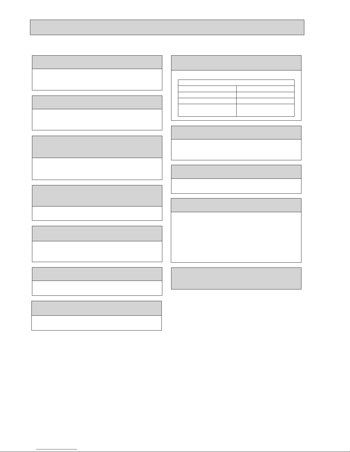
[1] Cautions for service
(1) Perform service after recovering the refrigerant left in unit completely.
(2) Do not release refrigerant in the air.
(3) After completing service, charge the cycle with specified amount of refrigerant.
(4) When performing service, install a filter drier simultaneously.
Be sure to use a filter drier for new refrigerant.
[2] Additional refrigerant charge
When charging directly from cylinder
· Check that cylinder for R410A on the market is syphon type.
· Charging should be performed with the cylinder of syphon stood vertically. (Refrigerant is charged from liquid phase.)
Gravimeter
Unit
[3] Service tools
Use the below service tools as exclusive tools for R410A refrigerant.
No.
Tool name Specifications
1
Gauge manifold · Only for R410A
· Use the existing fitting
specifications
. (UNF1/2)
· Use high-tension side pressure of 5.3MPa·G or over.
2
Charge hose · Only for R410A
· Use pressure performance of 5.09MPa·G or over.
3
Electronic scale
—
4
Gas leak detector · Use the detector for R134a, R407C or R410A.
5
Adaptor for reverse flow check · Attach on vacuum pump.
6
Refrigerant charge base
—
7
Refrigerant cylinder · Only for R410A · Top of cylinder (Pink)
· Cylinder with syphon
8
Refrigerant recovery equipment
—
OCH447B
6
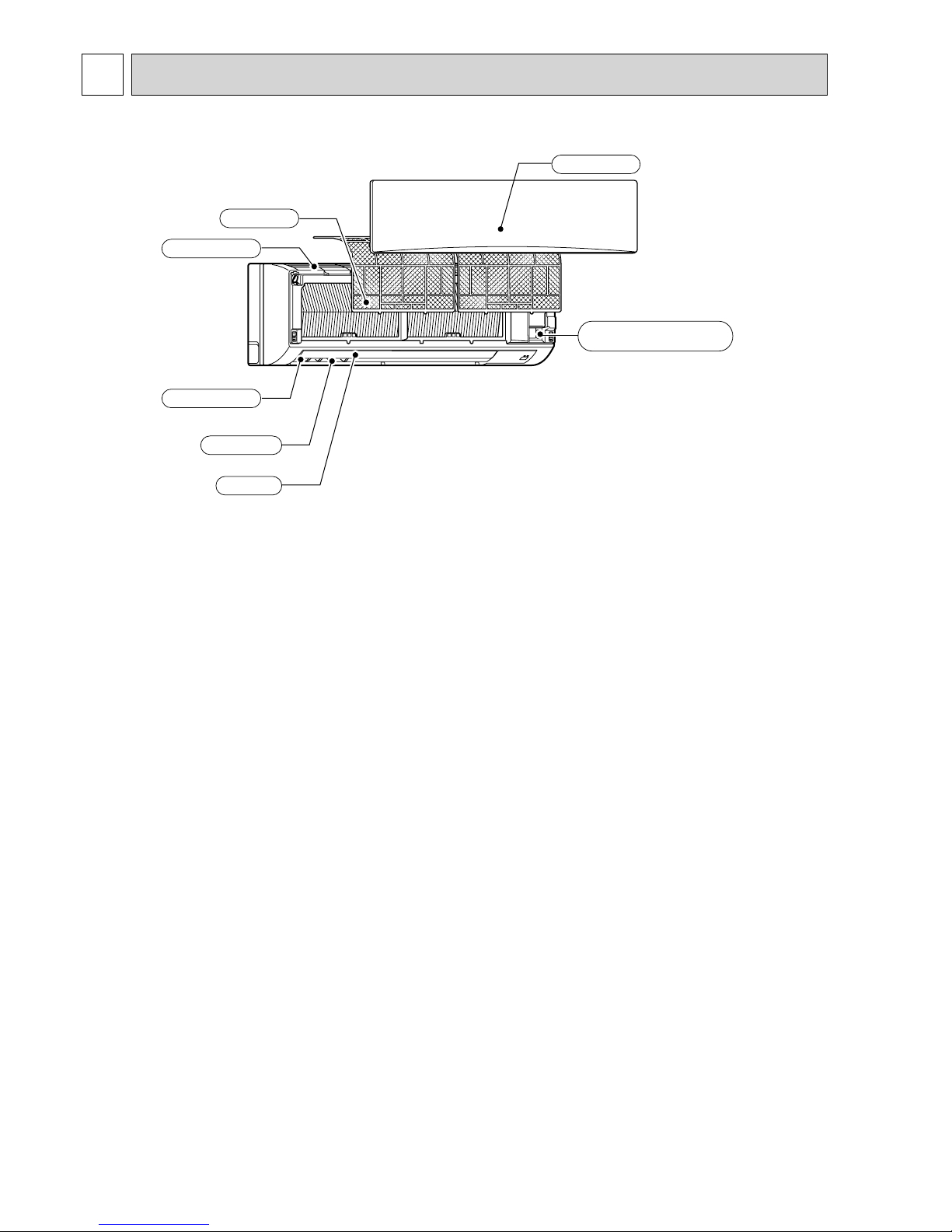
3-1. Indoor unit
3
PART NAMES AND FUNCTIONS
Emergency
operation
switch
Front grille
Air inlet
Filter
Air outlet
Louver
Vane
OCH447B
77
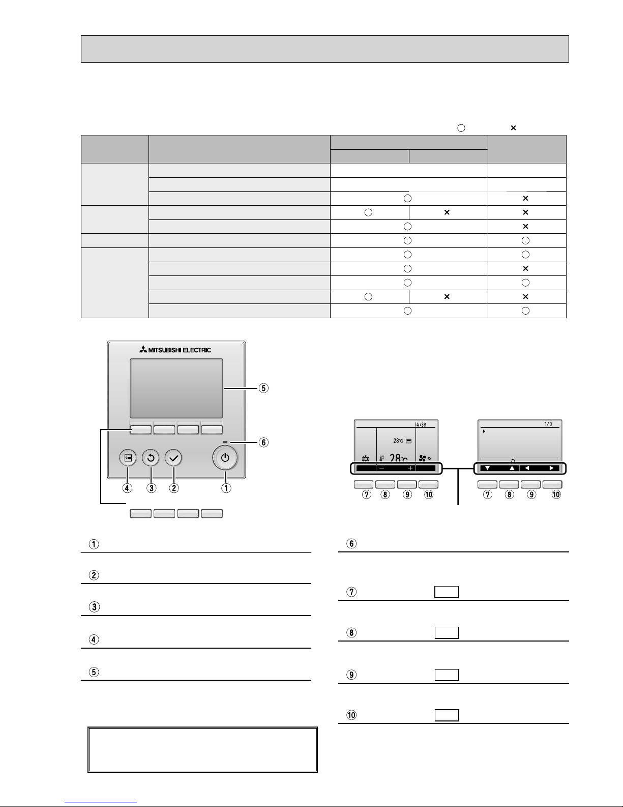
Function buttons
F1 F2 F3 F4
Press to turn ON/OFF the indoor unit.
ON / OFF button
When the backlight is off, pressing any button turns
the backlight on and does not perform its function.
(except for the (ON / OFF) button)
The functions of the function buttons change depending on
the screen. Refer to the button function guide that appears
at the bottom of the LCD for the functions they serve on a
given screen.
When the system is centrally controlled, the button function
guide that corresponds to the locked button will not appear.
Press to save the setting.
SELECT button
Press to return to the previous screen.
RETURN button
Press to bring up the Main menu.
MENU button
Operation settings will appear.
When the backlight is off, pressing any button turns the
backlight on and it will stay lit for a certain period of time
depending on the screen.
Backlit LCD
This lamp lights up in green while the unit is in operation.
It blinks while the remote controller is starting up or when
there is an error.
ON / OFF lamp
Main display : Press to change the operation mode.
Main menu : Press to move the cursor down.
Function button
F1
Main display : Press to decrease temperature.
Main menu : Press to move the cursor up.
Function button
F2
Main display : Press to increase temperature.
Main menu : Press to go to the previous page.
Function button
F3
Main display : Press to change the fan speed.
Main menu : Press to go to the next page.
Function button
F4
Fri
Room
Set temp.
Mode Tem p . Fa n
Cool Auto
Main
Main display:
Cursor Page
Main menu
Vane·Louver·Vent. (Lossnay)
High power
Timer
Weekly timer
OU silent mode
<Main display> <Main menu>
Function guide
3-2. WIRED REMOTE CONTROLLER <PAR-30MAA/PAR-31MAA>
* The functions which can be used are restricted according to the model.
: Supported : Unsupported
Function
PAR-30MAA/PAR-31MAA
PAR-21MAA
Slim City multi
Body Product size H × W × D (mm) 120 × 120 × 19 120 × 130 × 19
LCD Full Dot LCD Partial Dot LCD
Backlight
Energy-saving Energy-saving operation schedule
Automatic return to the preset temperature
Restriction Setting the temperature range restriction
Function Operation lock function
Weekly timer
On / Off timer
High Power
Manual vane angle
Wired remote controller function
OCH447B
8
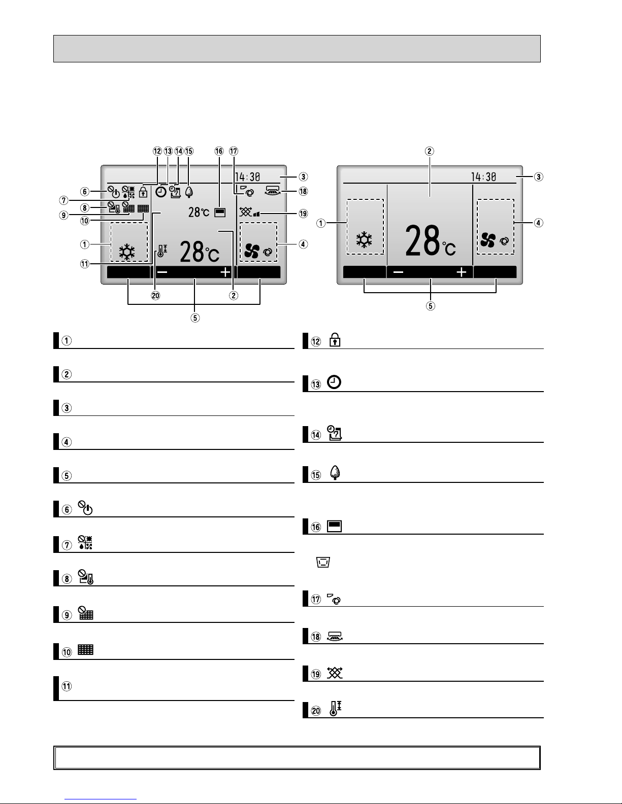
Fri
Mode Temp. Fan
Room
Cool Auto
Set temp.
Fri
Cool
Mode Temp. Fan
AutoSet temp.
The main display can be displayed in two different modes: "Full" and "Basic".
T
he factory setting is "Full". To switch to the "Basic" mode, change the setting on the Main display setting.
<Full mode> <Basic mode>
* All icons are displayed for explanation.
Most settings (except ON / OFF, mode, fan speed, temperature) can be made from the Menu screen.
Indoor unit operation mode appears here.
Operation mode
Preset temperature appears here.
Preset temperature
Current time appears here.
Clock (See the Installation Manual.)
Fan speed
Fan speed setting appears here.
Functions of the corresponding buttons appear here.
Button function guide
Appears when the ON/OFF operation is centrally controlled.
Appears when the operation mode is centrally controlled.
Appears when the preset temperature is centrally controlled.
Appears when the f lter reset function is centrally controlled.
Indicates when f lter needs maintenance.
Current room temperature appears here.
Room temperature
(See the Installation Manual.)
Appears when the buttons are locked.
Appears when the On/Off timer or Night setback function is
enabled.
Appears when the Weekly timer is enabled.
Appears while the units are operated in the energy-save
mode.
Appears when the built-in thermistor on the remote controller is activated to monitor the room temperature (a).
appears when the thermistor on the indoor unit is acti-
vated to monitor the room temperature.
Indicates the vane setting.
Indicates the louver setting.
Indicates the ventilation setting.
Appears when the preset temperature range is restricted.
OCH447B
9
Not all functions are available on all models of indoor units.
Filter information
Error information
Energy saving
Auto return
Schedule
Night setback
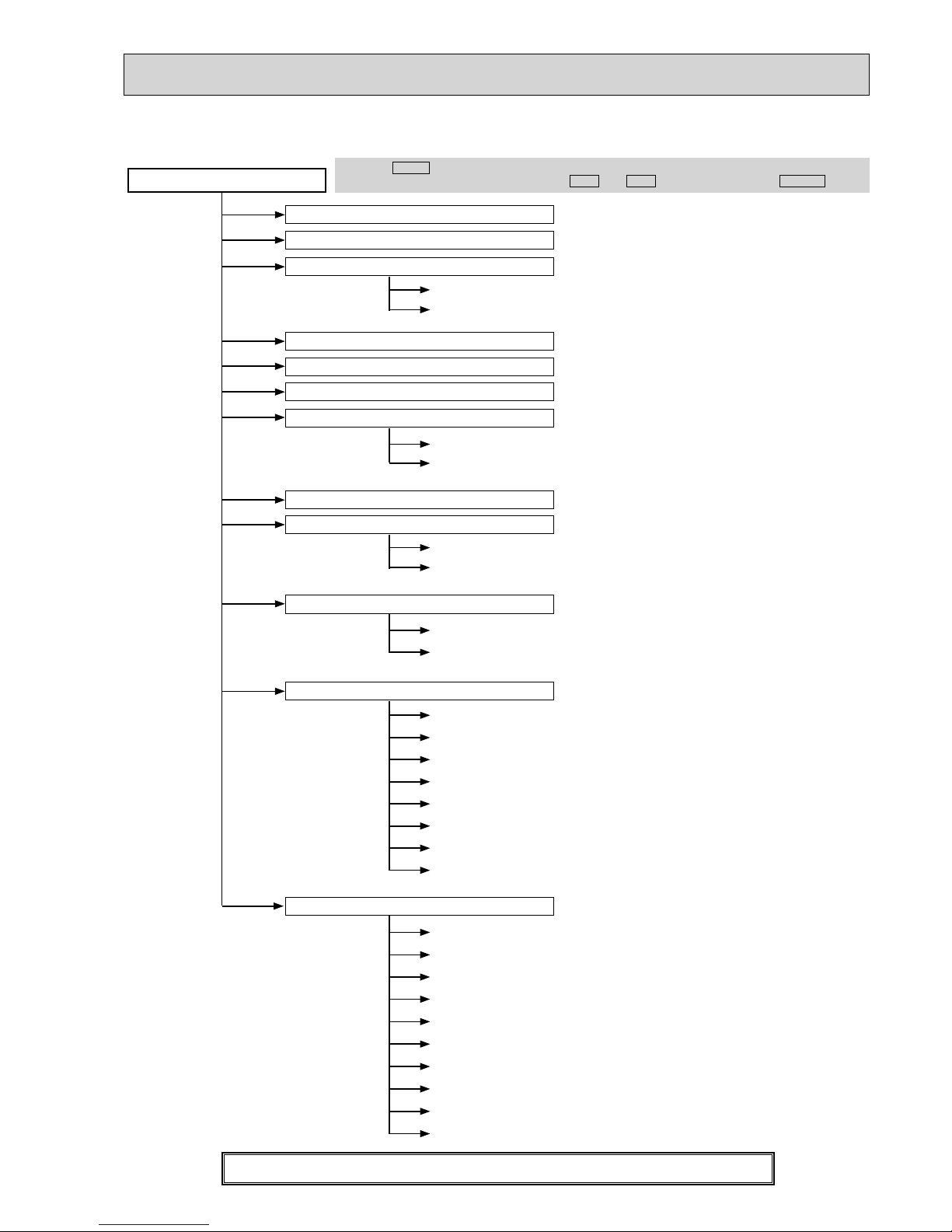
Main menu
Press the
MENU
button.
Move the cursor to the desired item with the
F1
and
F2
buttons, and press the
SELECT
button.
Vane · Louver · Vent. (Lossnay)
High power
Weekly timer
Restriction
Maintenance
Initial setting
On / Off timer
Auto-Off timer
Temp. range
Operation lock
Manual vane angle
Main / Sub
Timer
Main display
Contrast
Display details
Auto mode
Administrator password
Language selection
Service
Service menu
Input maintenance info.
Function setting
Lossnay (City Multi only)
Check
Self check
Maintenance password
Remote controller check
Test run
Clock
Drain pump test run
Auto descending panel
Menu structure
OCH447B
 Loading...