

Mitsubishi Electric PKFY-P20VBM-E, PKFY-P20VHM-E, PCFY-P20VKM-E, PFFY-P20VKM-E2, PMFY-P20VBM-E OPERATION MANUAL
...
Air-Conditioners For Building Application
INDOOR UNIT
PKFY-P·VBM-E / PKFY-P·VHM-E
PCFY-P·VKM-E / PFFY-P·VKM-E2 / PMFY-P·VBM-E
OPERATION MANUAL
For safe and correct use, please read this operation manual thoroughly before operating the air-conditioner unit.
BEDIENUNGSHANDBUCH
Zum sicheren und einwandfreien Gebrauch der Klimaanlage dieses Bedienungshandbuch vor Inbetriebnahme
gründlich durchlesen.
MANUEL D’UTILISATION
Pour une utilisation correcte sans risques, veuillez lire le manuel d’utilisation en entier avant de vous servir du
climatiseur.
BEDIENINGSHANDLEIDING
Voor een veilig en juist gebruik moet u deze bedieningshandleiding grondig doorlezen voordat u de
airconditioner gebruikt.
MANUAL DE INSTRUCCIONES
Lea este manual de instrucciones hasta el final antes de poner en marcha la unidad de aire acondicionado
para garantizar un uso seguro y correcto.
ISTRUZIONI DI FUNZIONAMENTO
Leggere attentamente questi istruzioni di funzionamento prima di avviare l’unità, per un uso corretto e sicuro
della stessa.
ΕΓΧΕΙΡΙΔΙΟ ΟΔΗΓΙΩΝ ΧΡΗΣΕΩΣ
Για ασφάλεια και σωστή χρήση, παρακαλείστε διαβάσετε προσεχτικά αυτό το εγχειρίδιο χρήσεως πριν θέσετε
σε λειτουργία τη μονάδα κλιματισμού.
MANUAL DE OPERAÇÃO
Para segurança e utilização correctas, leia atentamente o manual de operação antes de pôr a funcionar a unidade de ar condicionado.
FOR USER
FÜR BENUTZER
POUR L’UTILISATEUR
VOOR DE GEBRUIKER
PARA EL USUARIO
PER L’UTENTE
ΓΙΑ ΤΟΝ ΧΡΗΣΤΗ
PARA O UTILIZADOR
English (GB)
Deutsch (D)
Français (F)
Nederlands (NL)
Español (E)
Italiano (I)
Ελληνικά (GR)
Português (P)
Işletme Elkitabı
Emniyetli ve doğru biçimde nasıl kullanılacağını öğrenmek için lütfen klima cihazını işletmeden önce bu
elkitabını dikkatle okuyunuz.
РУКОВОДСТВО ПО ЭКСПЛУАТАЦИИ
Для обеспечения правильного и безопасного использования следует ознакомиться с инструкциями, указанными в
данном руководстве по эксплуатации, тщательным образом до того, как приступать к использованию кондиционера.
KULLANICI İÇİN
Türkçe (TR)
ДЛЯ ПОЛЬЗОВАТЕЛЯ
Русский (RU)
Contents
1. Safety Precautions .................................................................2
2. Parts Names ...........................................................................3
3. Operation ................................................................................7
4. Timer.....................................................................................10
This symbol mark is for EU countries only.
Note
Fig.1
Note:
The phrase “Wired remote controller” in this operation manual refers to the PAR-31MAA.
If you need any information for the other remote controller, please refer to the instruction book included in this box.
This symbol mark is according to the directive 2012/19/EU Article 14 Information for users and Annex IX, and/or to
the directive 2006/66/EC Article 20 Information for end-users and Annex II.
Your MITSUBISHI ELECTRIC product is designed and manufactured with high quality materials and components which can be
recycled and/or reused. This symbol means that electrical and electronic equipment, batteries and accumulators, at their end-oflife, should be disposed of separately from your household waste. If a chemical symbol is printed beneath the symbol (Fig. 1), this
chemical symbol means that the battery or accumulator contains a heavy metal at a certain concentration.
This will be indicated as follows: Hg: mercury (0,0005%), Cd: cadmium (0,002%), Pb: lead (0,004%)
In the European Union there are separate collection systems for used electrical and electronic products, batteries and accumulators.
Please, dispose of this equipment, batteries and accumulators correctly at your local community waste collection/recycling centre.
Please, help us to conserve the environment we live in!
5. Emergency Operation for Wireless Remote-controller .........10
6. Care and Cleaning................................................................11
7. Troubleshooting ....................................................................13
8. Specifications .......................................................................15
1. Safety Precautions
Before installing the unit, make sure you read all the
“Safety Precautions”.
The “Safety Precautions” provide very important
points regarding safety. Make sure you follow them.
GB
Please report to or take consent by the supply
authority before connection to the system.
Symbols used in the text
Warning:
Describes precautions that should be observed to prevent danger
of injury or death to the user.
Caution:
Describes precautions that should be observed to prevent damage
to the unit.
Warning:
• These appliances are not accessible to the general public.
• The unit must not be installed by the user. Ask the dealer or an
authorized company to install the unit. If the unit is installed
improperly, water leakage, electric shock or fire may result.
• Do not stand on, or place any items on the unit.
• Do not splash water over the unit and do not touch the unit with
wet hands. An electric shock may result.
• Do not spray combustible gas close to the unit. Fire may result.
• Do not place a gas heater or any other open-flame appliance
where it will be exposed to the air discharged from the unit.
Incomplete combustion may result.
• Do not remove the front panel or the fan guard from the outdoor
unit when it is running.
• Never repair the unit or transfer it to another site by yourself.
• When you notice exceptionally abnormal noise or vibration, stop
operation, turn off the power switch, and contact your dealer.
• Never insert fingers, sticks etc. into the air inlets or outlets.
• If you detect odd smells, stop using the unit, turn off the power
switch and consult your dealer. Otherwise, a breakdown, electric
shock or fire may result.
• This air conditioner is NOT intended for use by children or infirm
persons without supervision.
• If the refrigeration gas blows out or leaks, stop the operation of
the air conditioner, thoroughly ventilate the room, and contact
your dealer.
• This appliance is intended to be used by expert or trained users
in shops, in light industry and on farms, or for commercial use by
lay persons.
Symbols used in the illustrations
: Indicates a part which must be grounded.
• Young children must be supervised to ensure that they do not
play with the air conditioner.
• This appliance is not intended for use by persons (including
children) with reduced physical, sensory or mental capabilities,
or lack of experience and knowledge, unless they have been
given supervision or instruction concerning use of the appliance
by a person responsible for their safety.
• This appliance can be used by children aged from 8 years and
above and persons with reduced physical, sensory or mental
capabilities or lack of experience and knowledge if they have
been given supervision or instruction concerning use of the
appliance in a safe way and understand the hazards involved.
Children shall not play with the appliance. Cleaning and user
maintenance shall not be made by children without supervision.
• When installing or relocating, or servicing the air conditioner, use
only the specified refrigerant (R410A) to charge the refrigerant
lines. Do not mix it with any other refrigerant and do not allow air
to remain in the lines.
If air is mixed with the refrigerant, then it can be the cause of
abnormal high pressure in the refrigerant line, and may result in
an explosion and other hazards. The use of any refrigerant other
than that specified for the system will cause mechanical failure
or system malfunction or unit breakdown. In the worst case, this
could lead to a serious impediment to securing product safety.
Caution:
• Do not use any sharp object to push the buttons, as this may
damage the remote controller.
•
Never block or cover the indoor or outdoor unit’s air inlets or outlets
• Never wipe the remote controller with benzene, thinner chemical
rags, etc.
• Do not operate the unit for a long time in high humidity, e.g.
leaving a door or window open. In the cool mode, if the unit is
operated in a room with high humidity (80% RH or more) for a
2
long time, water condensed in the air conditioner may drop and
wet or damage furniture, etc.
.
• Do not touch the upper air outlet vane or the lower air outlet
damper during operation. Otherwise, condensation may form and
the unit may stop operating.
Disposing of the unit
When you need to dispose of the unit, consult your dealer.
2. Parts Names
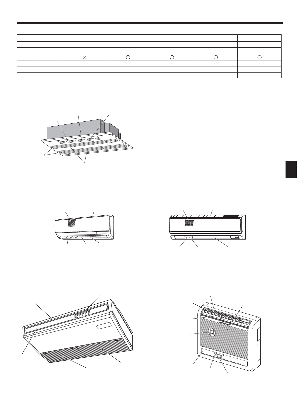
■ Indoor Unit
PKFY-P·VBM-E PKFY-P·VHM-E PCFY-P·VKM-E PMFY-P·VBM-E PFFY-P·VKM-E2
Fan speed 4 speed 3 speed+ Auto* 4 speed+ Auto* 4 speed 4 speed
Vane
Louver Manual Manual Manual Manual Manual
Filter Normal Normal Long-life Normal Normal
Filter cleaning indication
■ PMFY-P·VBM-E
1-way Ceiling Cassette
Steps 4 steps 5 steps 5 steps 4 steps 4 steps
Auto swing
100 hr 100 hr 2,500 hr 100 hr 100 hr
* This operation is available only using the remote controller
that is able to set its Fan speed setting "Auto".
Vane
Air outlet
Filter
Louver
■ PKFY-P·VBM-E
Wall Mounted
■ PCFY-P·VKM-E
Ceiling Suspended
Air outlet
Filter
Louver
Air inlet
Air intake
Air outlet
Vane
Louver
■ PKFY-P·VHM-E
Wall Mounted
Filter
Louver
■ PFFY-P·VKM-E2
Floor Standing
Air outlet
Air outlet
GB
Air intake
Vane
Louver
Air inlet
Vane
Air intake
Filter
(Inside of Air intake)
Vane
Filter
Vane
Air outlet
Louver
3
2. Parts Names
■
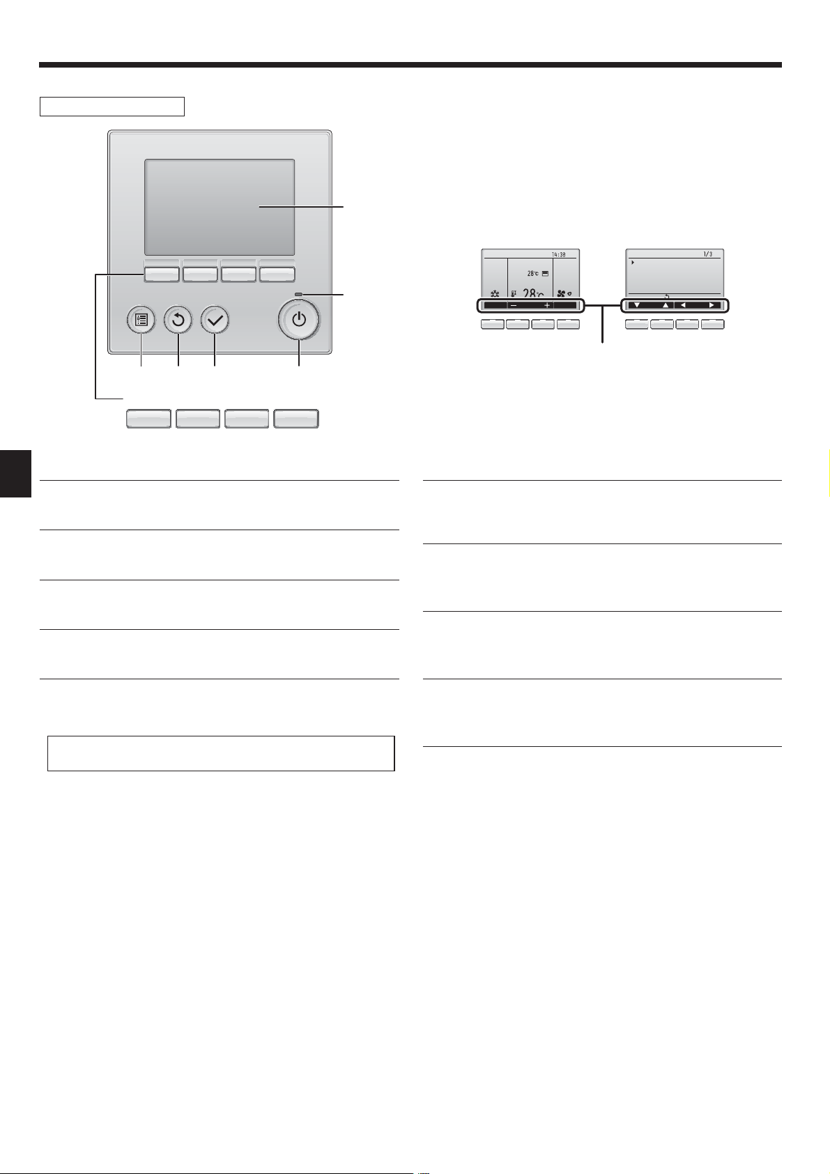
Wired Remote Controller
Controller interface
The functions of the function buttons change depending on the
screen.
Refer to the button function guide that appears at the bottom of the
LCD for the functions they serve on a given screen.
When the system is centrally controlled, the button function guide
that corresponds to the locked button will not appear.
Function buttons
▌ [ON/OFF] button
GB
Press to turn ON/OFF the indoor unit.
▌ [SELECT] button
Press to save the setting.
▌ [RETURN] button
Press to return to the previous screen.
▌ [MENU] button
Press to bring up the Main menu.
Main display Main menu
Room
Set temp.
Cool Auto
Mode Temp. Fan
Fri
Main
Main menu
Vane·Louver·Vent. (Lossnay)
High power
Timer
Weekly timer
OU silent mode
Main display:
Cursor Page
Function guide
▌ ON/OFF lamp
This lamp lights up in green while the unit is in operation. It blinks while
the remote controller is starting up or when there is an error.
▌ Function button [F1]
Main display: Press to change the operation mode.
Main menu: Press to move the cursor down.
▌ Function button [F2]
Main display: Press to decrease temperature.
Main menu: Press to move the cursor up.
▌ Backlit LCD
Operation settings will appear.
When the backlight is off, pressing any button turns the backlight on
and it will stay lit for a certain period of time depending on the screen.
When the backlight is off, pressing any button turns the backlight on
and does not perform its function. (except for the [ON/OFF] button)
▌ Function button [F3]
Main display: Press to increase temperature.
Main menu: Press to go to the previous page.
▌ Function button [F4]
Main display: Press to change the fan speed.
Main menu: Press to go to the next page.
4
2. Parts Names
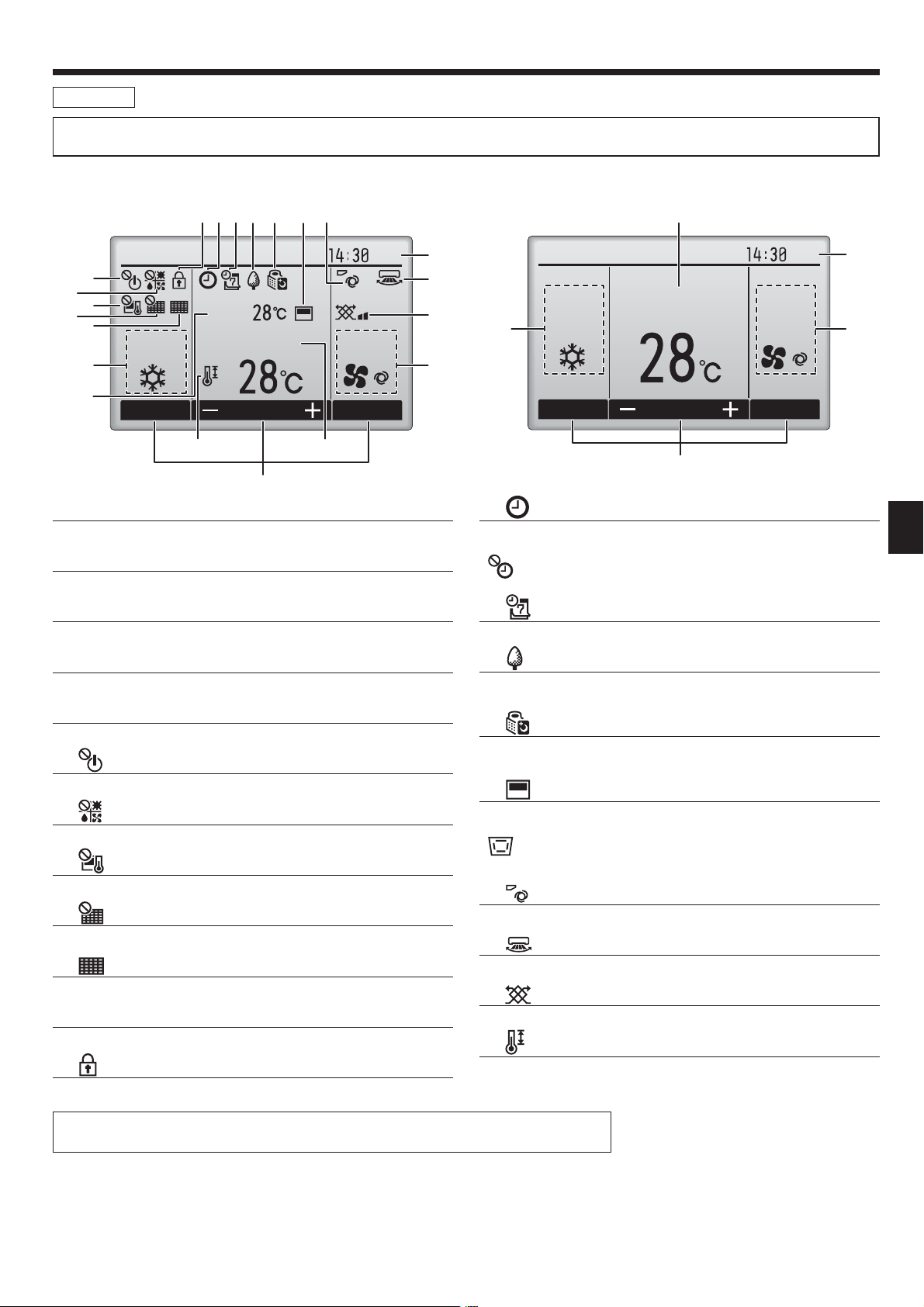
Display
The main display can be displayed in two different modes: “Full” and “Basic”. The factory setting is “Full”. To switch to the “Basic” mode, change the
setting on the Main display setting. (Refer to operation manual included with remote controller.)
<Full mode>
* All icons are displayed for explanation.
Cool Auto
Room
Set temp.
Mode Temp. Fan
▌ Operation mode
Indoor unit operation mode appears here.
▌ Preset temperature
Preset temperature appears here.
▌ Clock (See the Installation Manual.)
Current time appears here.
<Basic mode>
Fri
Fri
Cool
AutoSet temp.
Mode Temp. Fan
▌
Appears when the On/Off timer, Night setback, or Auto-off timer
function is enabled.
appears when the timer is disabled by the centralized control
system.
▌
Appears when the Weekly timer is enabled.
GB
▌ Fan speed
Fan speed setting appears here.
▌ Button function guide
Functions of the corresponding buttons appear here.
▌
Appears when the ON/OFF operation is centrally controlled.
▌
Appears when the operation mode is centrally controlled.
▌
Appears when the preset temperature is centrally controlled.
▌
Appears when the filter reset function is centrally controlled.
▌
Indicates when filter needs maintenance.
▌ Room temperature (See the Installation Manual.)
Current room temperature appears here.
▌
Appears when the buttons are locked.
▌
Appears while the units are operated in the energy-save mode. (Will
not appear on some models of indoor units)
▌
Appears while the outdoor units are operated in the silent mode.
(This indication is not available for CITY MULTI models.)
▌
Appears when the built-in thermistor on the remote controller is
activated to monitor the room temperature ().
appears when the thermistor on the indoor unit is activated to
monitor the room temperature.
▌
Indicates the vane setting.
▌
Indicates the louver setting.
▌
Indicates the ventilation setting.
▌
Appears when the preset temperature range is restricted.
Most settings (except ON/OFF, mode, fan speed, temperature) can be made from the Menu screen.
(Refer to operation manual included with remote controller.)
5
2. Parts Names
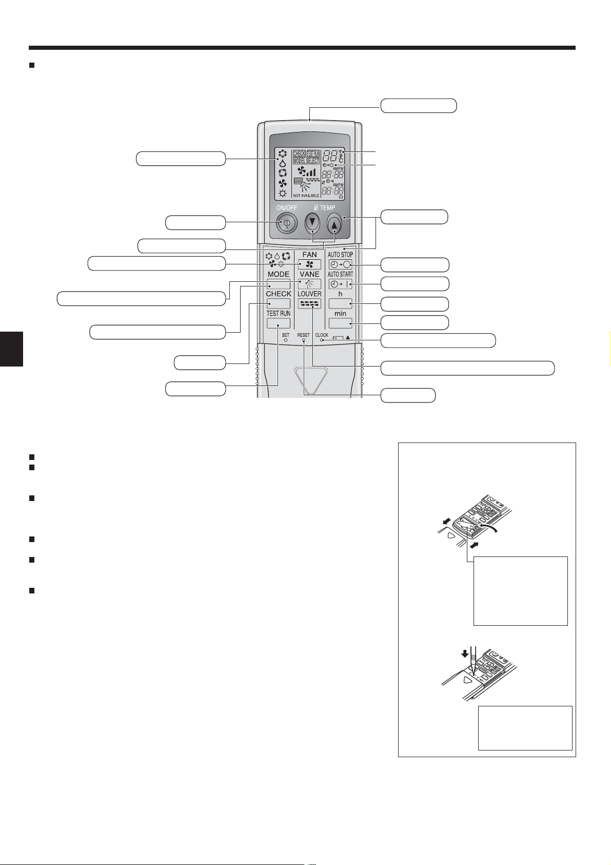
Wireless Remote-Controller (Optional parts)
Transmission area
Remote controller display
* For explanation purposes, all of the items
that appear in the display are shown.
* All items are displayed when the Reset
button is pressed.
ON/OFF button
Set Temperature buttons
Fan Speed button (Changes fan speed)
Airflow button (Changes up/down airflow direction)
Mode button (Changes operation mode)
GB
Check button
Test Run button
Note (Only for wireless remote controller):
When using the wireless remote controller, point it towards the receiver on the indoor unit.
If the remote controller is operated within approximately 2 minutes after power is supplied to
the indoor unit, the indoor unit may beep twice as the unit is performing the initial automatic
check.
The indoor unit beeps to confirm that the signal transmitted from the remote controller has
been received. Signals can be received up to approximately 7 meters in a direct line from the
indoor unit in an area 45° to the left and right of the unit. However, illumination such as fluorescent lights and strong light can affect the ability of the indoor unit to receive signals.
If the operation lamp near the receiver on the indoor unit is blinking, the unit needs to be in-
spected. Consult your dealer for service.
Handle the remote controller carefully! Do not drop the remote controller or subject it to strong
shocks. In addition, do not get the remote controller wet or leave it in a location with high humidity.
To avoid misplacing the remote controller, install the holder included with the remote controller
on a wall and be sure to always place the remote controller in the holder after use.
Transmission indicator
Timer indicator
Operation areas
Timer Off button
Timer On button
Hour button
Minute button
Set Time button (Sets the time)
Louver button (Changes left/right airflow direction)
Reset button
Battery installation/replacement
1. Remove the top cover, insert two AAA batteries, and then install the top cover.
1
2
Top cover
3
Two AAA batteries
Insert the negative (–)
end of each battery first.
Install the batteries in
the correct directions
(+, –)!
2. Press the Reset button.
Press the Reset button
with an object that has
a narrow end.
6
3. Operation
■
About the operation method, refer to the operation manual that comes with each remote controller.
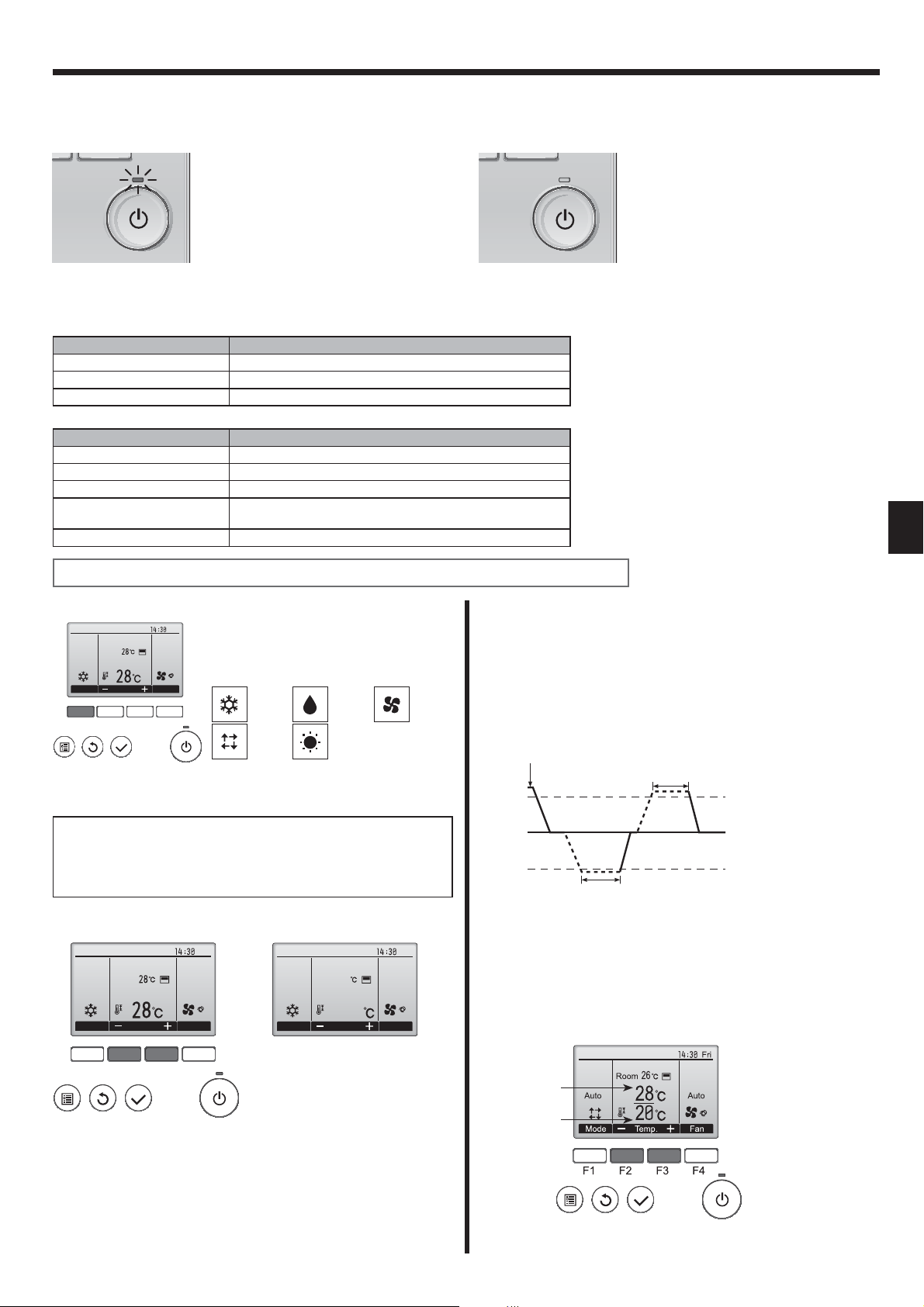
3.1. Turning ON/OFF
[ON] [OFF]
Press the [ON/OFF] button.
The ON/OFF lamp will light up in
green, and the operation will start.
Note:
Even if you press the ON/OFF button immediately after shutting down the operation is progress, the air conditioner will not start for about 3 minutes.
This is to prevent the internal components from being damaged.
■
Operation status memory
Remote controller setting
Operation mode Operation mode before the power was turned off
Preset temperature Preset temperature before the power was turned off
Fan speed Fan speed before the power was turned off
■
Settable preset temperature range
Operation mode Preset temperature range
Cool/Dry 19 ~ 30 ºC
Heat 17 ~ 28 ºC
Auto (Single set point) 19 ~ 28 ºC
Auto (Dual set points) [Cool] Preset temperature range for the Cool mode
[Heat] Preset temperature range for the Heat mode
Fan/Ventilation Not settable
Press the [ON/OFF] button again.
The ON/OFF lamp will come off,
and the operation will stop.
GB
The settable temperature range varies with the model of outdoor units and remote controller.
3.2. Mode Selection
Fri
Room
Cool
Mode Temp. Fan
F1 F2 F3 F4
AutoSet temp.
Press the [F1] button to go through the operation modes in the order of “Cool”, “Dry”,
“Fan”, “Auto”, and “Heat”. Select the desired
operation mode.
Cool Dry Fan
Auto Heat
Automatic operation (single set point)
■ According to a set temperature, cooling operation starts if the room
temperature is too hot and heating operation starts if the room
temperature is too cold.
■ During automatic operation, if the room temperature changes and
remains 1.5 °C or more above the set temperature for 3 minutes, the
air conditioner switches to cool mode. In the same way, if the room
temperature remains 1.5 °C or more below the set temperature for
3 minutes, the air conditioner switches to heat mode.
Cool mode
• Operation modes that are not available
to the connected outdoor unit models will
not appear on the display.
What the blinking mode icon means
The mode icon will blink when other indoor units in the same refrigerant
system (connected to the same outdoor unit) are already operated in a
different mode. In this case, the rest of the unit in the same group can
only be operated in the same mode.
3.3. Temperature setting
<Cool, Dry, Heat, and Auto (single set point)>
Fri
Room
Cool
Mode Temp. Fan
F1 F2 F3 F4
AutoSet temp.
Cool
Mode Temp. Fan
(Centigrade in 0.5-degree increments)
Room
28.5
28.5
Example display
Fri
AutoSet temp.
maintain a fixed effective temperature, cooling operation is performed
a few degrees warmer and heating operation is performed a few
degrees cooler than the set room temperature once the temperature is
reached (automatic energy-saving operation).
<Auto (dual set point) mode>
Preset temperature
for cooling
Preset temperature
for heating
■ Because the room temperature is automatically adjusted in order to
3 minutes (switches
from cooling to heating)
Press the [F2] button to decrease the preset temperature, and press the
[F3] button to increase.
• Refer to the table on page 7 for the settable temperature range for different operation modes.
• Preset temperature range cannot be set for Fan/Ventilation operation.
• Preset temperature will be displayed either in Centigrade in 0.5- or
1-degree increments, or in Fahrenheit, depending on the indoor unit
model and the display mode setting on the remote controller.
The current preset temperatures will appear. Press the [F2] or [F3]
button to display the Settings screen.
3 minutes (switches
from heating to cooling)
Set temperature +1.5°C
Set temperature
Set temperature -1.5°C
7
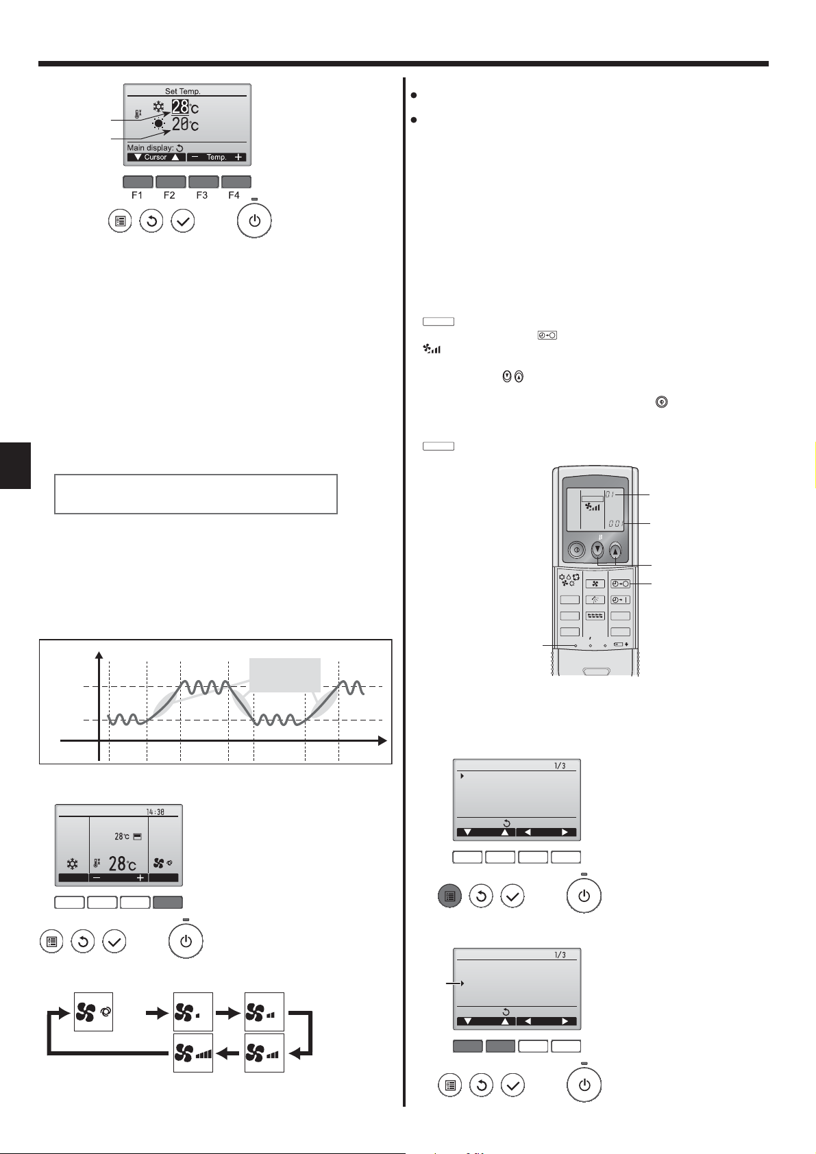
3. Operation
Preset temperature
for cooling
Preset temperature
for heating
Press the [F1] or [F2] button to move the cursor to the desired
temperature setting (cooling or heating).
Press the [F3] button to decrease the selected temperature, and [F4]
to increase.
• Refer to the table on page 7 for the settable temperature range for
different operation modes.
• The preset temperature settings for cooling and heating in the
Auto (dual set point) mode are also used by the Cool/Dry and Heat
modes.
• The preset temperatures for cooling and heating in the Auto (dual
set point) mode must meet the conditions below:
• Preset cooling temperature is higher than preset heating temperature.
• The minimum temperature difference requirement between cooling and
heating preset temperatures (varies with the models of indoor units
connected) is met.
* If preset temperatures are set in a way that does not meet the minimum
temperature difference requirement, both preset temperatures will
GB
automatically be changed within the allowable setting ranges.
Navigating through the screens
• To return to the Main screen ...... [RETURN] button
Note:
The number of available fan speeds depends on the type of unit connected.
Note also that some units do not provide an “Auto” setting.
In the following cases, the actual fan speed generated by the unit will differ
from the speed shown the remote controller display.
1. While the display is showing “STAND BY” or “DEFROST”.
2. When the temperature of the heat exchanger is low in the heat mode.
(e.g. immediately after heat operation starts)
3. In HEAT mode, when room temperature is higher than the temperature
setting.
4. When the unit is in DRY mode.
■ Automatic fan speed setting (For wireless remote controller)
It is necessary to set for wireless remote controller only when automatic
fan speed is not set at default setting.
It is not necessary to set for wired remote controller with automatic fan
speed at default setting.
Press the SET button with something sharp at the end.
Operate when display of remote controller is off.
MODEL SELECT
blinks and Model No. is lighted .
Press the AUTO STOP button.
blinks and setting No. is lighted .
(Setting No.01: without automatic fan speed)
Press the temp. buttons to set the setting No.02.
(Setting No.02: with automatic fan speed)
If you mistook the operation, press the ON/OFF button and
again from procedure .
Press the SET button with something sharp at the end.
MODEL SELECT
and Model No. are lighted for 3 seconds, then turned off.
MODEL SELECT
operate
<Auto operation (dual set point) mode>
When the operation mode is set to the Auto (dual set point) mode, two
preset temperatures (one each for cooling and heating) can be set.
Depending on the room temperature, indoor unit will automatically
operate in either the Cool or Heat mode and keep the room temperature
within the preset range.
The graph below shows the operation pattern of indoor unit operated in
the Auto (dual set point) mode.
Operation pattern during Auto (dual set point) mode
The room temperature
Preset temp.
(COOL)
Preset temp.
(HEAT)
changes corresponding
to the change in the
outside temperature.
Room
temperature
HEAT COOL HEAT COOL
3.4. Fan speed setting
Fri
Room
Cool
Mode Temp. Fan
F1 F2 F3 F4
Press the [F4] button to go through the fan speeds in the following order.
AutoSet temp.
Auto
ON/OFF TEMP
FAN
AUTO STOP
VANE
LOUVER
RESETSET CLOCK
AUTO START
h
min
MODE
CHECK
TEST RUN
3.5. Airflow direction setting
3.5.1 Navigating through the Main menu
<Accessing the Main menu>
Main
Vane·Louver·Vent. (Lossnay)
High power
Timer
Weekly timer
OU silent mode
Main display:
Cursor Page
F1 F2 F3 F4
<Item selection>
Main
Vane·Louver·Vent. (Lossnay)
Cursor
High power
Timer
Weekly timer
OU silent mode
Main display:
Cursor Page
Main menu
Main menu
Press the [MENU] button.
The Main menu will appear.
Press [F1] to move the cursor down.
Press [F2] to move the cursor up.
• The available fan speeds depend on the models of connected indoor
units.
8
F1 F2 F3 F4
3. Operation
<Navigating through the pages>
Main menu
Main
Vane·Louver·Vent. (Lossnay)
High power
Timer
Weekly timer
OU silent mode
Main display:
Cursor Page
F1 F2 F3 F4
page
<Saving the settings>
OU silent mode
Mon Tue Wed Thu Fri Sat Sun
Start Stop Silent
-
Setting display:
day
F1 F2 F3 F4
<Exiting the Main menu screen>
Fri
Room
Cool
Mode Temp. Fan
F1 F2 F3 F4
AutoSet temp.
Press [F3] to go to the previous
page.
Press [F4] to go to the next page.
Select the desired item, and press
the [SELECT] button.
The screen to set the selected item
will appear.
Press the [RETURN] button to exit
the Main menu and return to the
Main display.
If no buttons are touched for
10 minutes, the screen will
automatically return to the Main
display. Any settings that have not
been saved will be lost.
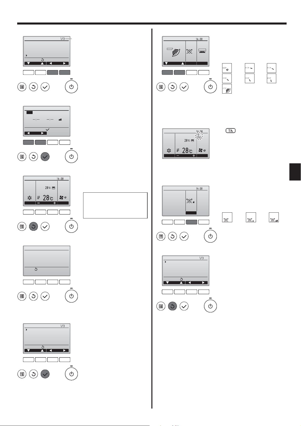
<Vane setting>
Swing Off Off
F1 F2 F3 F4
Room
Cool
Mode Temp. Fan
<Vent. setting>
Low
Vent.
Fri
Press the [F1] or [F2] button to go
through the vane setting options:
"Auto", "Step 1", "Step 2", "Step 3",
"Step 4", "Step 5" and "Swing".
Select the desired setting.
LouverVent.Vane
Auto
Swing
Auto
Swing
Step 1 Step 2
Step 4Step 3
Step 5
Select "Swing" to move the vanes
up and down automatically.
When set to "Step 1" through "Step
5", the vane will be fixed at the selected angle.
•
Fri
under the vane setting icon
This icon will appear when the
AutoSet temp.
vane is set to "Step 2" to "Step 5"
and the fan operates at "Mid 1"
to "Low" speed during cooling or
dry operation (depends on the
model).
The icon will go off in an hour, and
the vane setting will automatically
change.
Fri
Press the [F3] button to go through
the ventilation setting options in the
GB
order of "Off", "Low", and "High".
* Settable only when LOSSNAY
unit is connected.
Off Low High
Off Low High
<Display of unsupported functions>
Title
Not available
Unsupported function
Return:
F1 F2 F3 F4
3.5.2 Vane·Vent. (Lossnay)
<Accessing the menu>
Main
Main menu
Vane·Louver·Vent. (Lossnay)
High power
Timer
Weekly timer
OU silent mode
Main display:
Cursor Page
F1 F2 F3 F4
The message at left will appear if
the user selects a function not supported by the corresponding indoor
unit model.
Select "Vane·Louver·Vent. (Lossnay)" from the Main menu (refer to
page 8), and press the [SELECT]
button.
F1 F2 F3 F4
• The fan on some models of indoor units may be interlocked
with certain models of ventilation
units.
<Returning to the Main menu>
Main
Main menu
Vane·Louver·Vent. (Lossnay)
High power
Timer
Weekly timer
OU silent mode
Main display:
Cursor Page
F1 F2 F3 F4
Press the [RETURN] button to go
back to the Main menu.
Note:
During swing operation, the directional indication on the screen
●
does not change in sync with the directional vanes on the unit.
● Available directions depend on the type of unit connected.
In the following cases, the actual air direction will differ from the
●
direction indicated on the remote controller display.
1. While the display is in “STAND BY” or “DEFROST” states.
2. Immediately after starting heat mode (while the system is wait-
ing for the mode change to take effect).
3. In heat mode, when room temperature is higher than the tem-
perature setting.
9
3. Operation
<[Manual] To Change the Airflow's Left/Right Direction>
* The louver button cannot be used.
• Stop the unit operation, hold the lever of the louver,
and adjust to the desired direction.
* Do not set to the inside direction when the unit is in
the cooling or drying mode because there is a risk of
condensation and water dripping.
Caution:
To prevent falls, maintain a stable footing when operating the unit.
3.6. Ventilation
For LOSSNAY combination
■ The following 2 patterns of operation is available.
• Run the ventilator together with indoor unit.
• Run the ventilator independently.
Note: (for wireless remote controller)
● Running the ventilator independently is not available.
● No indication on the remote controller.
4. Timer
4.1. For Wired Remote-controller
■ Timer functions are different by each remote controller.
■ For details on how to operate the remote controller, refer to the appropriate operation manual included with each remote controller.
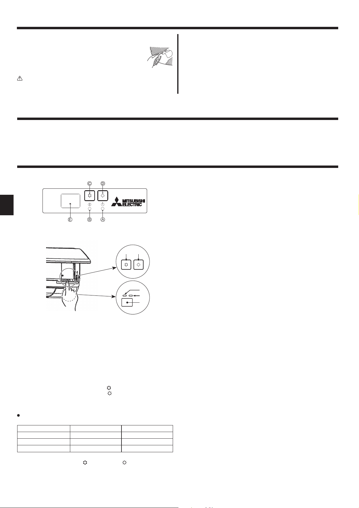
5. Emergency Operation for Wireless Remote-controller
5. Emergency Operation for Wireless Remote-controller
GB
(For PKFY-P·VHM-E)
When the remote controller cannot be used
When the batteries of the remote controller run out or the remote controller malfunctions, the emergency operation can be done using the
emergency buttons on the grille.
DEFROST/STAND BY lamp
Operation lamp
Emergency operation cooling switch
Emergency operation heating switch
Receiver
Starting operation
• To operate the cooling mode, press the
• To operate the heating mode, press the button for more than 2 seconds.
• Lighting of the Operation lamp means the start of operation.
Note:
Details of emergency mode are as shown below.
Details of EMERGENCY MODE are as shown below.
Operation mode COOL HEAT
Set temperature 24°C 24°C
Fan speed High High
Airflow direction Horizontal Downward 4 (5)
Stopping operation
• To stop operation, press the
button or the button for more than 2 seconds.
button for more than 2 seconds.
10

6. Care and Cleaning
■ Filter information
Fri
Room
Cool
Mode Temp. Fan
Main
Main menu
Restriction
Energy saving
Night setback
Filter information
Error information
Main display:
Cursor Page
F1 F2 F3 F4
AutoSet temp.
will appear on the Main display
in the Full mode when it is time to
clean the filters.
Wash, clean, or replace the filters
when this sign appears.
Refer to the indoor unit Instructions Manual for details.
Select "Filter information" from the
Main menu (refer to page 8), and
press the [SELECT] button.
Room
Cool
Mode Temp. Fan
AutoSet temp.
Fri
When the
Main display in the Full mode, the
system is centrally controlled and
the filter sign cannot be reset.
is displayed on the
If two or more indoor units are connected, filter cleaning timing for
each unit may be different, depending on the filter type.
The icon
will appear when the filter on the main unit is due for
cleaning.
When the filter sign is reset, the cumulative operation time of all units
will be reset.
The icon
is scheduled to appear after a certain duration of
operation, based on the premise that the indoor units are installed in a
space with ordinary air quality. Depending on the air quality, the filter
may require more frequent cleaning.
The cumulative time at which filter needs cleaning depends on the
model.
• This indication is not available for wireless remote controller.
Filter information
Please clean the filter.
Press Reset button after
filter cleaning.
Main menu:
F1 F2 F3 F4
Filter information
Reset filter sign?
F1 F2 F3 F4
Filter information
Reset
Cancel
OK
Press the [F4] button to reset filter
sign.
Refer to the indoor unit Instructions
Manual for how to clean the filter.
Select "OK" with the [F4] button.
A confirmation screen will appear.
Cleaning the filters
• Clean the filters using a vacuum cleaner. If you do not have a vacuum
cleaner, tap the filters against a solid object to knock off dirt and dust.
• If the filters are especially dirty, wash them in lukewarm water. Take
care to rinse off any detergent thoroughly and allow the filters to dry
completely before putting them back into the unit.
Caution:
• Do not dry the filters in direct sunlight or by using a heat source,
such as an electric heater: this may warp them.
• Do not wash the filters in hot water (above 50°C), as this may
warp them.
• Make sure that the air filters are always installed. Operating the
unit without air filters can cause malfunction.
Caution:
• Before you start cleaning, stop operation and turn OFF the power
supply.
• Indoor units are equipped with filters to remove the dust of suckedin air. Clean the filters using the methods shown in the following
sketches.
Caution:
• In removing the filter, precautions must be taken to protect your
eyes from dust. Also, if you have to climb up on a stool to do the
job, be careful not to fall.
• When the filter is removed, do not touch the metallic parts inside
the indoor unit, otherwise injury may result.
GB
Filter sign reset
Main menu:
Navigating through the screens
• To go back to the Main menu ................ [MENU] button
• To return to the previous screen ...........[RETURN] button
11

6. Care and Cleaning
■ PCFY-P·VKM-E
Open the intake grille.
Hold the knob on the filter then pull the filter up in the direction of
an arrow. To replace the filter after cleaning, be sure to insert the
filter far enough until it fits into the stopper.
Filter Intake Grille Knob Stopper
GB
■ PMFY-P·VBM-E
■ PFFY-P·VKM-E2
Remove the catechin air filter.
Open the front grille
Catechin air filter
Caution:
When the catechin air filter is to be removed, do not touch the
metal parts of the indoor unit.
This may cause an injury.
Install the catechin air filter.
Be sure to install its both ends into the tabs as shown.
Install
Securely close the front grille.
Pressing the PUSH button on the outer side of the intake grille
causes the intake grille to open.
A filter with an intake grille on it can be removed by pulling the filter
forward.
■ PKFY-P·VBM-E
PKFY-P·VHM-E
Pull both the bottom corners of the intake grille to open the grille,
then lift the filter.
12

7. Troubleshooting
Having trouble? Here is the solution. (Unit is operating normally.)
Air conditioner does not heat or cool well.
When heating operation starts, warm air does not blow from the indoor
unit soon.
During heat mode, the air conditioner stops before the set room
temperature is reached.
Airflow up/down direction changes during operation or airflow up/down
direction cannot be set.
When the airflow up/down direction is changed, the vanes always move
up and down past the set position before finally stopping at the position.
A flowing water sound or occasional hissing sound is heard.
A cracking or creaking sound is heard.
The room has an unpleasant odor.
A white mist or vapor is emitted from the indoor unit.
Water or vapor is emitted from the outdoor unit.
The air conditioner does not operate even though the ON/OFF button
is pressed. The operation mode display on the remote controller
disappears.
“
” appears in the remote controller display.
When restarting the air conditioner soon after stopping it, it does not
operate even though the ON/OFF button is pressed.
Air conditioner operates without the ON/OFF button being pressed.
Air conditioner stops without the ON/OFF button being pressed.
Remote controller timer operation cannot be set.
“PLEASE WAIT” appears in the remote controller display.
An error code appears in the remote controller display.
Draining water or motor rotation sound is heard.
■ Clean the filter. (Airflow is reduced when the filter is dirty or clogged.)
■ Check the temperature adjustment and adjust the set temperature.
■ Make sure that there is plenty of space around the outdoor unit. Is the
indoor unit air inlet or outlet blocked?
■ Has a door or window been left open?
■ Warm air does not blow until the indoor unit has sufficiently warmed
up.
■ When the outdoor temperature is low and the humidity is high,
frost may form on the outdoor unit. If this occurs, the outdoor unit
performs a defrosting operation. Normal operation should begin after
approximately 10 minutes.
■ During cool mode, the vanes automatically move to the horizontal
(down) position after 1 hour when the down (horizontal) airflow up/
down direction is selected. This is to prevent water from forming and
dripping from the vanes.
■ During heat mode, the vanes automatically move to the horizontal
airflow up/down direction when the airflow temperature is low or
during defrosting mode.
■ When the airflow up/down direction is changed, the vanes move to the
set position after detecting the base position.
■ These sounds can be heard when refrigerant is flowing in the air
conditioner or when the refrigerant flow is changing.
■ These sounds can be heard when parts rub against each due to
expansion and contraction from temperature changes.
■ The indoor unit draws in air that contains gases produced from the
walls, carpeting, and furniture as well as odors trapped in clothing,
and then blows this air back into the room.
■ If the indoor temperature and the humidity are high, this condition may
occur when operation starts.
■ During defrosting mode, cool airflow may blow down and appear like a
mist.
■ During cool mode, water may form and drip from the cool pipes and
joints.
■ During heat mode, water may form and drip from the heat exchanger.
■ During defrosting mode, water on the heat exchanger evaporates and
water vapor may be emitted.
■ Is the power switch of the indoor unit turned off? Turn on the power
switch.
■ During central control, “ ” appears in the remote controller display
and air conditioner operation cannot be started or stopped using the
remote controller.
■ Wait approximately three minutes.
(Operation has stopped to protect the air conditioner.)
■ Is the on timer set?
Press the ON/OFF button to stop operation.
■ Is the air conditioner connected to a central remote controller?
Consult the concerned people who control the air conditioner.
■ Does “ ” appear in the remote controller display?
Consult the concerned people who control the air conditioner.
■ Has the auto recovery feature from power failures been set?
Press the ON/OFF button to stop operation.
■ Is the off timer set?
Press the ON/OFF button to restart operation.
■ Is the air conditioner connected to a central remote controller?
Consult the concerned people who control the air conditioner.
■ Does “ ” appear in the remote controller display?
Consult the concerned people who control the air conditioner.
■ Are timer settings invalid?
If the timer can be set, or appears in the remote controller
display.
■ The initial settings are being performed. Wait approximately 3
minutes.
■ The protection devices have operated to protect the air conditioner.
■ Do not attempt to repair this equipment by yourself.
Turn off the power switch immediately and consult your dealer. Be
sure to provide the dealer with the model name and information that
appeared in the remote controller display.
■ When cooling operation stops, the drain pump operates and then
stops. Wait approximately 3 minutes.
GB
13

7. Troubleshooting
Having trouble? Here is the solution. (Unit is operating normally.)
Noise is louder than specifications.
Nothing appears in the wireless remote controller display, the display
is faint, or signals are not received by the indoor unit unless the
remote controller is close.
The operation lamp near the receiver for the wireless remote
controller on the indoor unit is blinking.
Warm air blows from the indoor unit intermittently when heating mode
is off or during fan mode.
The damper opens and closes automatically.
(For PFFY-P·VKM-E2)
■ The indoor operation sound level is affected by the acoustics of the
particular room as shown in the following table and will be higher than
the noise specification, which was measured in an echo-free room.
High sound-
absorbing
rooms
Location
examples
Noise levels 3 to 7 dB 6 to 10 dB 9 to 13 dB
Broadcasting
studio, music
room, etc.
Normal rooms
Reception
room, hotel
lobby, etc.
Low sound-
absorbing
rooms
Office, hotel
room
■ The batteries are low.
Replace the batteries and press the Reset button.
■ If nothing appears even after the batteries are replaced, make sure that
the batteries are installed in the correct directions (+, –).
■ The self diagnosis function has operated to protect the air conditioner.
■ Do not attempt to repair this equipment by yourself.
Turn off the power switch immediately and consult your dealer. Be sure
to provide the dealer with the model name.
■ When another indoor unit is operating in heating mode, the control valve
opens and closes occasionally to maintain stability in the air conditioning
system. This operation will stop after a while.
* If this will cause an undesirable rise in the room temperature in small
rooms, etc., stop the operation of the indoor unit temporarily.
■ The damper is automatically controlled by a microcomputer according to
the air flow temperature and operation time of the air conditioner.
GB
Air outlet control (PFFY-P·VKM-E2)
This unit is automatically controlled that air comes out simultaneously from the upper and lower air outlets so that the room can be cooled or heated
effectively.
Description of operation
Operation COOL DRY HEAT FAN
Air flow
Upper and lower air flow
Room temperature
and set
Conditions
• Be sure to keep the area around the damper of the lower air outlet free of any objects.
This unit can be set to blow out air from the upper air outlet only by changing the switch setting on the address board (ask the dealer).
Range of application
The range of working temperatures for both the indoor and outdoor units of the series Y, R2, Multi-S is as below.
Warning:
If the air conditioner operates but does not cool or heat (depending on model) the room, consult your dealer since there may be a
refrigerant leak. Be sure to ask the service representative whether there is refrigerant leakage or not when repairs are carried out.
The refrigerant charged in the air conditioner is safe. Refrigerant normally does not leak. However, if refrigerant gas leaks indoors, and
comes into contact with the fire of a fan heater, space heater, stove, etc., harmful substances will be generated.
temperature are
different.
Upper air flow Upper air flow only
Room temperature
is close to set
temperature or
thermo-off.
—
Upper and lower air flow
(Normal condition
(in heating))
Upper air flow
During defrosting
operation, start of
operation, thermooff
Upper and lower air flow
—
14

8. Specifications
■ PCFY-P·VKM-E
Model P40 P63 P100 P125
Power source (Voltage/Frequency) <V/Hz> ~/N 220-230-240/50, 220/60
Capacity (Cooling/Heating) <kW> 4.5/5.0 7.1/8.0 11.2/12.5 14.0/16.0
Dimension (Height) <mm> 230
Dimension (Width) <mm> 960 1280 1600
Dimension (Depth) <mm> 680
Net weight <kg> 24 32 36 38
Fan Airflow rate (Low-Middle2-Middle1-High) <m
Noise level (Low-Middle2-Middle1-High) <dB> 29-32-34-36 31-33-35-37 36-39-41-43 36-39-42-44
Note
* Operation temperature of indoor unit.
Cooling mode: 15 °CWB - 24 °CWB
Heating mode: 15 °CDB - 27 °CDB
*1 Cooling/Heating capacity indicates the maximum value at operation under the following condition.
Cooling: Indoor 27 °C DB/19°C WB, Outdoor 35 °C DB
Heating: Indoor 20 °C DB, Outdoor 7 °C DB/6 °C WB
■ PKFY-P·VBM-E ■ PKFY-P·VHM-E
Model P15 P20 P25 P32 P40 P50
Power source (Voltage/Frequency) <V/Hz> ~/N 220-230-240/50, 220/60
Capacity (Cooling/Heating) <kW> 1.7/1.9 2.2/2.5 2.8/3.2 3.6/4.0 4.5/5.0 5.6/6.3
Dimension (Height) <mm> 295 295
Dimension (Width) <mm> 815 898
Dimension (Depth) <mm> 225 249
Net weight <kg> 10 13
Fan Airflow rate (Low-Middle2-Middle1-High) <m
Noise level (Low-Middle2-Middle1-High) <dB> 29-31-32-33 29-31-34-36 34-37-41 34-38-41 34-39-43
Note
* Operation temperature of indoor unit.
Cooling mode: 15 °CWB - 24 °CWB
Heating mode: 15 °CDB - 27 °CDB
*1 Cooling/Heating capacity indicates the maximum value at operation under the following condition.
Cooling: Indoor 27 °C DB/19 °C WB, Outdoor 35 °C DB
Heating: Indoor 20 °C DB, Outdoor 7 °C DB/6 °C WB
■ PMFY-P·VBM-E
Model P20 P25 P32 P40
Power source (Voltage/Frequency) <V/Hz> ~/N 220-230-240/50, 220/60
Capacity (Cooling/Heating) <kW> 2.2/2.5 2.8/3.2 3.6/4.0 4.5/5.0
Dimension (Height) <mm> 230 (30)
Dimension (Width) <mm> 854 (1000)
Dimension (Depth) <mm> 395 (470)
Net weight <kg> 14 (3.0)
Fan Airflow rate (Low-Middle2-Middle1-High) <m
Noise level (Low-Middle2-Middle1-High) <dB> 27-30-33-36 32-34-36-37 33-35-37-39
Note
* Operation temperature of indoor unit.
Cooling mode: 15 °CWB - 24 °CWB
Heating mode: 15 °CDB - 27 °CDB
*1 Cooling/Heating capacity indicates the maximum value at operation under the following condition.
Cooling: Indoor 27 °C DB/19 °C WB, Outdoor 35 °C DB
Heating: Indoor 20 °C DB, Outdoor 7 °C DB/6 °C WB
*2 This figure ( ) indicates panel’s.
■ PFFY-P·VKM-E2
Model P20 P25 P32 P40
Power source (Voltage/Frequency) <V/Hz> ~/N 220-230-240/50
Capacity (Cooling/Heating) <kW> 2.2/2.5 2.8/3.2 3.6/4.0 4.5/5.0
Dimension (Height) <mm> 600
Dimension (Width) <mm> 700
Dimension (Depth) <mm> 200
Net weight <kg> 14
Fan Airflow rate (Low-Middle2-Middle1-High) <m
Noise level (Low-Middle2-Middle1-High) <dB> 27-31-34-37 28-32-35-38 35-38-42-44
Note
* Operation temperature of indoor unit.
Cooling mode: 15 °CWB - 24 °CWB
Heating mode: 15 °CDB - 27 °CDB
*1 Cooling/Heating capacity indicates the maximum value at operation under the following condition.
Cooling: Indoor 27 °C DB/19 °C WB, Outdoor 35 °C DB
Heating: Indoor 20 °C DB, Outdoor 7 °C DB/6 °C WB
3
/min> 10-11-12-13 14-15-16-18 21-24-26-28 21-24-27-31
3
/min>
3
/min>
3
/min>
4.9-5.0-5.2-5.3
6.5-7.2-8.0-8.6
5.9-6.8-7.6-8.7
4.9-5.2-5.6-5.9 9-10-11 9-10.5-11.5 9-10.5-12
7.3-8.0-8.6-9.3
6.1-7.0-8.0-9.1
7.7-8.7-9.7-10.7
8.0-9.0-9.5-10.7
GB
15

Содержание
1. Меры предосторожности ..................................................129
2. Наименование деталей ....................................................130
3. Эксплуатация ....................................................................134
4. Таймер ...............................................................................137
5. Работа пульта дистанционного управления в
аварийном режиме ...........................................................137
6. Уход и чистка .....................................................................138
7. Исправление неполадок ...................................................140
8. Технические характеристики............................................142
Примечание:
В этом руководстве по использованию аппарата фраза “проводной пульт дистанционного управления” относится к пульту
дистанционного управления PAR-31MAA.
Сведения о других пультах дистанционного управления приводятся в руководстве, находящемся в этой коробке.
1. Меры предосторожности
Перед установкой данного прибора, пожалуйста
обязательно прочитайте все “Меры предосторожности”.
В разделе “Меры предосторожности” изложены очень
важные сведения, касающиеся техники безопасности.
Обязательно следуйте этим инструкциям.
Пожалуйста уведомите соответствующий орган
электроснабжения или получите от него разрешение
перед подключением к системе электропитания.
Предупреждение:
• Запрещается бесконтрольный, несанкционированный доступ
посторонних лиц к приборам этого класса.
•
Данны прибор не должен устанавливаться пользователем.
Обратитесь к поставщику или в специализированное
предприятие и закажите установку прибора. При
неправильной установке может произойти утечка воды,
электрический шок или пожар.
• Никогда не занимайтесь ремонтом или переносом прибора не
кто иной место самостоятельно.
•
Не ставьте какие-либо посторонние предметы на прибор.
• Не проливайте на прибор воду и не дотрагивайтесь до
прибора мокрыми руками.
• Не разбрызгивайте вблизи от прибора горючий газ.
• Не снимайте переднюю панель или защиту вентилятора с
внешнего прибора, когда он работает.
• Никогда не занимайтесь ремонтом или переносом прибора не
кто иной место самостоятельно.
•
Если вы заметите ненормально сильный шум или вибрацию,
остановите прибор, отключите главный выключатель питания и
свяжитесь с вашим поставщиком.
• Никогда не вставляйте пальцы, палки и т.д. в отверстия
входа или выхода.
• Если вы почувствуете странные запахи, остановите
прибор, отключите питание и проконсультируйтесь с вашим
поставщиком. В противном случае может произойти поломка
прибора, пожар или электрошок.
•
Детям и немощным людям ЗАПРЕЩАЕТСЯ самостоятельно
пользоваться данным кондиционером воздуха.
•
Если происходит выброс или утечка газа хладагента,
остановите работу кондиционера, тщательно проветрите
помещение и свяжитесь с вашим поставщиком.
•
Данное изделие предназначено для эксплуатации
специалистами или специально обученными пользователями
в магазинах, в легкой промышленности и на фермах; кроме
Символика, используемая в тексте
Предупреждение:
Описывает меры предосторожности, которые следует
выполнять, чтобы избежать травмы или гибели пользователя.
Осторожно:
Описывает меры предосторожности, которые следует
выполнять, чтобы не повредить прибор.
Символы, указанные на иллюстрациях
: Указывает, что эта часть должна быть заземлена.
того, в коммерческих целях оно может использоваться
неспециалистами.
• Необходимо наблюдать за маленькими детьми с тем, чтобы
они не играли с кондиционером воздуха.
• Этот прибор не предназначен для использования его детьми,
инвалидами, а также лицами с недостаточным опытом и
квалификацией, до тех пор, пока они не пройдут обучение,
и не получат полный инструктаж по правилам безопасной
эксплуатации данного прибора у лица, ответственного за их
безопасность.
• Данным устройством могут пользоваться дети старше 8
лет и лица с ограниченными физическими, сенсорными или
умственными возможностями или недостаточным опытом
или знаниями под наблюдением ответственного лица или
после обучения пользованию устройством с разъяснением
правил безопасности и при условии понимания возможных
опасностей при его применении. Не позволяйте детям играть
с данным устройством. Очистка и техническое обслуживание
устройства не должны осуществляться детьми без
соответствующего контроля.
• При монтаже или перемещении, а также при обслуживании
кондиционера используйте только указанный хладагент
(R410A) для заполнения трубопроводов хладагента. Не
смешивайте его ни с каким другим хладагентом и не
допускайте наличия воздуха в трубопроводах.
Наличие воздуха в трубопроводах может вызывать скачки
давления, в результате которых может произойти взрыв или
другие повреждения. Использование любого хладагента,
отличного от указанного для этой системы, вызовет
механическое повреждение, сбои в работе системы, или
выход устройства из строя. В наихудшем случае, это может
послужить серьезной преградой к обеспечению безопасной
работы этого изделия.
Осторожно:
• Не пользуйтесь острыми предметами для нажатия
кнопок, так как это может привести к повреждению пульта
дистанционного управления.
• Не закрывайте и не блокируйте входные и выпускные
отверстия внутреннего и наружного блоков.
• Не протирайте пульт дистанционного управления тканью,
смоченной бензином, химическим растворителем и т. д.
• Запрещается длительная эксплуатация прибора в условиях
высокой влажности, например, в помещении с открытым
окном или дверью. Если прибор длительное время работает
в режиме охлаждения в помещении с высокой влажностью
(80% отн. влажности или выше), возможно капание влаги,
сконденсировавшейся в кондиционере. Это может повредить
мебель и т.д.
•
Не прикасайтесь к заслонке верхних воздуховыпускных
отверстий или демпферу нижних воздуховыпускных отверстий
во время эксплуатации. В противном случае, возможно
образование конденсата и прекращение работы прибора.
Утилизация прибора
Когда вам потребуется ликвидировать прибор, обратитесь к вашему
дилеру.
129
RU

2. Наименование деталей
■
Внутренний прибор
PKFY-P·VBM-E PKFY-P·VHM-E PCFY-P·VKM-E PMFY-P·VBM-E PFFY-P·VKM-E2
Скорость вращения вентилятора
Лопатка
Операции 4 шага 5 шага 5 шага 4 шага 4 шага
Автоотклонение
Жалюзи Вручную Вручную Вручную Вручную Вручную
Фильтр Обычный Обычный
Индикация очистки фильтра
■
PMFY-P·VBM-E
1-ходовая потолочная кассета
Выходные воздушные отверстия
Фильтр
4-х скоростная
3-х скоростная + Авто* 4-х скоростная + Авто*
Долговечный
4-х скоростная 4-х скоростная
Обычный Обычный
100 часов 100 часов 2.500 часов 100 часов 100 часов
* Даная операция доступна только при использовании пульта
дистанционного управления, с помощью которого можно установить настройки скорости вентилятора на “Авто”.
Лопатка
Жалюзи
■
PKFY-P·VBM-E
Монтаж на стене
Фильтр
Жалюзи Выходные
■
PCFY-P·VKM-E
Подвеска к потолку
Выходные воздушные отверстия
Выходные воздушные отверстия
Впуск воздуха
Лопатка
воздушные
отверстия
Жалюзи
■
PKFY-P·VHM-E
Монтаж на стене
Жалюзи
■
PFFY-P·VKM-E2
Выходные
воздушные
отверстия
Напольное расположение
Выходные воздушные
отверстия
Впуск воздухаФильтр
Лопатка
Жалюзи
Воздухозаборное
отверстие
RU
Лопатка
130
Выходные
воздушные
отверстия
Фильтр
(Внутренняя часть
воздухозаборника)
Лопатка
Фильтр
Лопатка
Выходные
воздушные
отверстия
Жалюзи

2. Наименование деталей
■
Проводной пульт дистанционного управления
Интерфейс контроллера
Функции функциональных кнопок меняются в зависимости от
экрана. См. подсказку по функциям кнопок, которая отображается в нижней части ЖК-экрана для функций, которые работают
в данном окне.
При централизованном управлении системой подсказка по фун-
кциям для заблокированных кнопок отображаться не будет.
Функциональные кнопки
▌ Кнопка [ВКЛ/ВЫКЛ]
Нажмите, чтобы включить или выключить внутренний блок.
▌ Кнопка [ВЫБОР]
Нажмите, чтобы сохранить настройку.
▌ Кнопка [ВОЗВРАТ]
Нажмите для возврата к предыдущему экрану.
▌ Кнопка [МЕНЮ]
Нажмите, чтобы открыть главное меню.
▌ Подсветка ЖК-экрана
Будут отображены параметры работы.
Когда подсветка выключена, нажатие на любую кнопку включит
подсветку, которая будет работать некоторое время в зависимости
от экрана.
Когда подсветка выключена, нажатие любой кнопки включает
подсветку, но не приводит к выполнению ее функции (кроме
кнопки [ВКЛ/ВЫКЛ]).
Главное окно Главное меню
Room
Set temp.
Cool Auto
Mode Temp. Fan
Fri
Main
Main menu
Vane·Louver·Vent. (Lossnay)
High power
Timer
Weekly timer
OU silent mode
Main display:
Cursor Page
Подсказка по функциям
▌ Индикатор ВКЛ/ВЫКЛ
Индикатор будет гореть зеленым цветом, когда устройство
находится в работе. Индикатор будет мигать при включении
контроллера или при возникновении ошибки.
▌ Функциональная кнопка [F1]
Главное окно: нажмите для изменения режима работы.
Главное меню: нажмите, чтобы переместить курсор вниз.
▌ Функциональная кнопка [F2]
Главное окно: нажмите для уменьшения температуры.
Главное меню: нажмите, чтобы переместить курсор верх.
▌ Функциональная кнопка [F3]
Главное окно: нажмите, чтобы увеличить температуру.
Главное меню: нажмите для перехода к предыдущей странице.
▌ Функциональная кнопка [F4]
Главное окно: нажмите, чтобы изменить скорость вентилятора.
Главное меню: нажмите для перехода к следующей странице.
131
RU

2. Наименование деталей
Индикация
Главное окно может отображаться в двух разных режимах: "полный" и "Базовый". Заводской настройкой по умолчанию являются "полный"
режим отображения. Чтобы переключиться в "Базовый" режим, измените параметр в настройке главного окна. См. руководство по
эксплуатации, входящее в комплект поставки пульта дистанционного управления.
<Полный режим отображения>
* Все значки показаны для иллюстрации и описания.
Cool Auto
Room
Set temp.
Mode Temp. Fan
▌ Режим работы
Здесь отображается режим работы внутреннего блока.
▌ Заданная температура
Здесь отображается заданная температура.
▌ Часы (См. руководство по установке.)
Здесь отображается текущее время.
Fri
<Базовый режим отображения>
Fri
Cool
AutoSet temp.
Mode Temp. Fan
▌
Отображается, когда включена функция "Таймер ВКЛ/ВЫКЛ",
"Ночной режим" или "Автоотключение" таймера.
появляется, когда таймер отключен централизованной
системой управления.
▌
Отображается, когда включен таймер на неделю.
▌ Скорость вентилятора
Здесь отображаются настройки скорости вентилятора.
▌ Подсказка по функциям кнопок
Здесь отображаются функции соответствующих кнопок.
▌
Отображается при централизованном управлении включением и
выключением.
▌
Отображается при централизованном управлении режимом
работы.
▌
Отображается при централизованном управлении заданной
температурой.
▌
Отображается при централизованном управлении функцией
сброса фильтра.
▌
Отображается при необходимости в обслуживании фильтра.
RU
▌
Комнатная температура (См. руководство по установке.)
Здесь отображается текущая комнатная температура.
▌
Отображается, пока изделие работает в режиме энергосбережения.
(не появится на некоторых моделях внутренних блоков)
▌
Отображается, пока наружный блок работает в "тихом" режиме.
(Эта индикация недоступна в моделях CITY MULTI.)
▌
Отображается, когда встроенный терморезистор на контроллере
включен для наблюдения за комнатной температурой ().
отображается, когда терморезистор на внутреннем блоке
включен для наблюдения за комнатной температурой.
▌
Отображает настройку угла.
▌
Отображает настройку жалюзи.
▌
Отображает настройку вентиляции.
▌
Отображается, когда ограничен диапазон заданных температур.
▌
Отображается, когда кнопки заблокированы.
Большая часть параметров (за исключением ВКЛ/ВЫКЛ, режима, скорости вентилятора и температуры) может быть настроена в
главном окне. См. руководство по эксплуатации, входящее в комплект поставки пульта дистанционного управления.
132

2. Наименование деталей
для беспроводного пульта дистанционного управления (раздел Дополнительное оборудование)
Область передачи
Дисплей пульта дистанционного управления
* В целях объяснения показаны все пункты, ко-
торые появляются на дисплее.
* Все пункты отображаются при нажатии кнопки
Reset (Сброс).
Кнопка “ON/OFF” (ВКЛ./ВЫКЛ.)
Кнопки установки температуры
Кнопка контроля скорости вентилятора
(Изменяет скорость вентилятора)
Кнопка воздушного потока (Изменяет направление
воздушного потока вверх/вниз)
Кнопка режима (Изменяет режим работы)
Кнопка проверки
Кнопка тестирования “Test”
Примечание (только для беспроводного пульта дистанционного управления):
При использовании беспроводного пульта дистанционного управления направьте
его к приемнику на внутреннем приборе.
Если пультом дистанционного управления воспользоваться примерно в течение
2 минут после подачи электропитания на внутренний прибор, внутренний
прибор может издать два звуковых сигнала, так как осуществляется начальная
автоматическая проверка.
Внутренний прибор издает звуковой сигнал, который подтверждает получение
сигнала, посланного с пульта дистанционного управления. Сигналы могут быть
получены на расстоянии примерно 7 метров по прямой линии от внутреннего
прибора под углом в 45° слева и справа прибора. Однако такой свет, как лампы
дневного света или сильное освещение могут уменьшить эффективность приема
сигналов внутренним прибором.
Если лампа работы около приемника на внутреннем приборе мигает, прибор
необходимо проверить. Свяжитесь со своим поставщиком для проведения
обслуживания.
Обращайтесь с пультом дистанционного управления осторожно! Не роняйте пульт
дистанционного управления и не подвергайте его сильным ударам. Кроме того,
следите за тем, чтобы пульт дистанционного управления не попал в воду, и не
оставляйте его в местах с высокой влажностью.
Во избежание неправильного местоположения пульта дистанционного управления,
установите на стене держатель, входящий в комплект поставки пульта
дистанционного управления, и обязательно устанавливайте пульт дистанционного
управления в держатель после использования.
Индикатор передачи
Индикатор таймера
Области работы
Кнопка отключение таймера
Кнопка включение таймера
Кнопка установки часов
Кнопка установки минут
Кнопка установки времени (Задает время)
Кнопка жалюзи (Изменяет направление
воздушного потока влево/вправо)
Кнопка Reset (Сброс)
Установка/замена батареек
1. Снимите верхнюю крышку, вставьте две
батарейки типа AAA и установите верхнюю
крышку на место.
1
2
3
Верхняя
крышка
2. Нажмите кнопку Reset (Сброс).
Две батарейки типа
AAA
Сначала вставляйте
отрицательный (–)
вывод каждой
батарейки.
Устанавливайте
батарейки с
соблюдением
полярности (+, –)!
Нажмите кнопку
Reset (Сброс) с
помощью предмета с
узким концом.
133
RU

3. Эксплуатация
■
Описание порядка пользования см. в руководстве пользователя, прилагаемом к каждому пульту дистанционного управления.
3.1. Включение/выключение
[ВКЛ] [ВЫКЛ]
Нажмите кнопку [ВКЛ/ВЫКЛ].
Индикатор ВКЛ/ВЫКЛ будет гореть
зеленым цветом, начнется работа.
Примечание:
Даже при нажатии кнопки ВКЛ/ВЫКЛ сразу после отключения выполняемой операции кондиционер запустится не ранее чем через 3 минуты.
Это предусмотрено во избежание повреждения внутренних компонентов.
■
Память состояния работы
Настройка удаленного контроллера
Режим работы Режим работы перед выключением питания
Заданная температура Заданная температура перед выключением питания
Скорость вентилятора Скорость вентилятора перед выключением питания
■
Настраиваемый диапазон задаваемой температуры
Режим работы Диапазон заданных температур
Охлаждение/сушка 19 – 30 ºC
Нагрев 17 – 28 ºC
Авт. (одно заданное значение)
Авт. (два заданных значения)
19 – 28 ºC
[Охлажд.] Заданный температурный диапазон для режима “Охлажд.”
[Нагрев] Заданный температурный диапазон для режима “Нагрев”
Вент. Не задается
Нажмите кнопку [ВКЛ/ВЫКЛ]
снова.
Индикатор ВКЛ/ВЫКЛ будет
погашен, работа будет
остановлена.
Устанавливаемый диапазон температур изменяется в зависимости от модели наружных приборов и пульта дистанционного управления.
3.2. Выбор режима
Fri
Room
Cool
Mode Temp. Fan
F1 F2 F3 F4
AutoSet temp.
Нажмите кнопку [F1] для перехода между
режимами работы в порядке “Cool” (Охлажд.), “Dry” (Сушка), “Fan” (Вент.), “Auto”
(Авт.) и “Heat” (Нагрев). Выберите желае-
мый режим работы.
Cool Dry Fan
Работа в автоматическом режиме (одно заданное значение)
■
В соответствии с заданной температурой, работа в режиме
охлаждения включается, если температура в помещении
слишком высокая, а работа в режиме обогрева включается, если
температура слишком низкая.
■
При работе в автоматическом режиме, если температура в
помещении изменится, и будет оставаться на 1,5 °C или больше
выше заданной температуры в течение 3 минут, кондиционер
переключается в режим охлаждения. Таким же образом, если
температура в помещении будет оставаться на 1,5 °C или больше
ниже заданной температуры в течение 3 минут, кондиционер
Auto Heat
• Режимы работы, которые не доступны
для подключенных моделей наружного
прибора, не появятся на дисплее.
Мигающие значки режимов
Значок режима будет мигать, когда другие внутренние блоки в
аналогичной группе кондиционирования (подключенной к одном
наружному блоку) уже работают в другом режиме. В этом случае
оставшиеся блоки в этой группе смогут работать только в этом режиме.
3.3. Настройка температуры
<“Cool” (Охлажд.), “Dry” (Сушка), “Heat” (Нагрев) и “Auto” (Авт.) (одно заданное значение)>
RU
Room
Cool
Mode Temp. Fan
F1 F2 F3 F4
AutoSet temp.
Fri
Room
Cool
Mode Temp. Fan
(по Цельсию с шагом 0,5 градуса)
28.5
28.5
Пример дисплея
Fri
AutoSet temp.
переключается в режим обогрева.
Режим охлаждения
3 минут (переключение с
охлаждения на обогрев)
■
Так как температура в помещении регулируется автоматически
3 минут (переключение с
обогрева на охлаждение)
Заданная
температура +1,5°C
Заданная
температура
Заданная
температура -1,5°C
для поддержания определенной эффективной температуры,
работа в режиме охлаждения осуществляется на несколько
градусов теплее, а работа в режиме обогрева на несколько
градусов холоднее заданной температуры при достижении
температуры (автоматическая экономия электроэнергии).
<Режим “Auto” (Авт.) (два заданных значения)>
Заданная температура
для охлаждения
Заданная температура
для нагрева
Нажмите кнопку [F2], чтобы уменьшить заданную температуру, а чтобы увеличить – нажмите кнопку [F3].
• Задаваемые диапазоны температур для различных режимов рабо-
ты см. в таблице на стр. 134.
• Заданный температурных диапазон не может быть установлен для
работы вентилятора.
•
В зависимости от модели внутреннего блока и настройки режима экрана на
пульте дистанционного управления, заданная температура будет отобра-
Отобразятся текущие значения температур. Нажмите клавишу
[F2] или [F3], чтобы отобразить экран настройки.
жаться по Цельсию, с шагом в 0,5 или 1 градус, или по Фаренгейту.
134

3. Эксплуатация
Заданная температура
для охлаждения
Заданная температура
для нагрева
Нажмите кнопку [F1] или [F2] для перемещения стрелки к
необходимой настройке температуры (охлаждения или нагрева).
Нажмите кнопку [F3] для уменьшения выбранной температуры и
[F4] для увеличения.
• Задаваемый температурный диапазон для различных режимов
операции см. в таблице на стр. 134.
•
Заданные настройки температуры для охлаждения и нагрева в
режиме “Auto” (Авт.) (два заданных значения) также используются
режимами “Cool” (Охлажд.)/“Dry” (Сушка) и “Heat” (Нагрев).
• Заданные значения температур для охлаждения и нагрева
в режиме “Auto” (Авт.) (два заданных значения) должны
соответствовать условиям, приведенным ниже:
•
Заданная температура охлаждения выше, чем заданная температура нагрева
• Выполняются минимальные требования разницы температуры между
заданными температурами охлаждения и нагрева (различается в
зависимости от модели подсоединенных внутренних блоков).
* Если заданные значения температур установлены способом, не
удовлетворяющим минимальные требования разницы температуры,
оба значения температуры автоматически изменяются в пределах
допустимых настроек диапазонов.
Навигация по экранам
• Для возврата к главному экрану .... кнопка [ВОЗВРАТ]
Примечание:
Число доступных скоростей вращения вентилятора зависит от
типа подключенного устройства. Некоторые устройства не имеют
возможности настройки параметра “Auto” (Авто).
В следующих случаях действительная скорость вентилятора
устройства будет отличаться от скорости, отображаемой на пульте
дистанционного управления.
1. Если дисплей используется в режиме “STAND BY” (ОЖИДАНИЕ) или
“DEFROST” (ОТТАИВАНИЕ).
2. Когда температура теплообменника низкая в режиме обогрева.
(например, сразу же после начала работы в режиме обогрева)
3. В режиме обогрева (HEAT), когда окружающая температура в
помещении выше значений настроек температуры.
4. Во время работы устройства в режиме сушки (DRY).
■
Автоматическая настройка скорости вентилятора (для беспровод-
ного пульта дистанционного управления)
Настройки пульта дистанционного управления следует выполнять
только в том случае, если автоматическая настройка скорости
вентилятора не является настройкой по умолчанию.
Выполнять такую настройку для проводного пульта дистанционного
управления, если параметр автоматической настройки скорости
вентилятора используется по умолчанию, не надо.
Нажмите кнопку SET остроконечным предметом.
Выполняйте операцию, когда дисплей пульта дистанционного
управления выключен.
MODEL SELECT
мигает и номер модели высвечивается как .
Нажмите кнопку AUTO STOP .
мигает и настройка номера модели высвечивается как .
(Настройка №01: без автоматической настройки скорости вентилятора)
Нажмите кнопки установки температуры,
(Настройка №02: с автоматической настройкой скорости вентилятора)
чтобы выбрать настройку №02.
При неправильном выборе операции нажмите кнопку ON/OFF
(ВКЛ./ВЫКЛ.) и вновь начните выполнение операции с пункта .
Нажмите кнопку SET остроконечным предметом.
MODEL SELECT
и номер модели высвечиваются в течение 3 секунд, а затем гаснут.
<Автоматический режим работы (двойная уставка)>
Когда операционный режим установлен в режим “Auto” (Авт.)
(два заданных значения), могут быть установлены два значения
температур (отдельно для охлаждения и для нагрева). В зависимости
от температуры помещения, внутренний блок автоматически
начнет работать в режиме “Cool” (Охлажд.) или “Heat” (Нагрев) и
поддерживать температуру комнаты в заданном диапазоне.
На рисунке ниже показан пример операции внутреннего блока,
работающего в режиме “Auto” (Авт.) (два заданных значения).
Пример операции режима Авт. (два заданных значения)
Температура в
Заданная
темп.
(«ОХЛАЖД.»)
Заданная
темп.
(«НАГРЕВ»)
«НАГРЕВ»
«ОХЛАЖД.»
комнате изменяется
в соответствии с
внешней температурой.
«НАГРЕВ»
Температура
в комнате
«ОХЛАЖД.»
3.4. Настройка скорости вентилятора
Fri
Room
Cool
Mode Temp. Fan
F1 F2 F3 F4
AutoSet temp.
MODEL SELECT
ON/OFF TEMP
h
min
MODE
CHECK
TEST RUN
FAN
VANE
LOUVER
RESETSET CLOCK
AUTO STOP
AUTO START
3.5. Настройка направления воздушного потока
3.5.1 Навигация по главному меню
<Доступ к главному меню>
Main
Main menu
Vane·Louver·Vent. (Lossnay)
High power
Timer
Weekly timer
OU silent mode
Main display:
Cursor Page
F1 F2 F3 F4
Нажмите кнопку [МЕНЮ].
Отобразится Главное меню.
Нажмите кнопку [F4] для перехода между скоростями вентилятора в
следующем порядке.
Auto
• Возможные скорости вентилятора зависят от моделей подключенных внутренних блоков.
<Выбор элементов>
Main
Main menu
Vane·Louver·Vent. (Lossnay)
Стрелка
High power
Timer
Weekly timer
OU silent mode
Main display:
Cursor Page
F1 F2 F3 F4
Нажмите [F1], чтобы переместить
курсор вниз.
Нажмите [F2], чтобы переместить
курсор вверх.
135
RU

3. Эксплуатация
<Навигация по страницам>
Main menu
Main
Vane·Louver·Vent. (Lossnay)
High power
Timer
Weekly timer
OU silent mode
Main display:
Cursor Page
F1 F2 F3 F4
Страница
Нажмите [F3] для перехода к предыдущей странице.
Нажмите [F4] для перехода к следующей странице.
<Сохранение настроек>
OU silent mode
Mon Tue Wed Thu Fri Sat Sun
Start Stop Silent
-
Setting display:
day
F1 F2 F3 F4
Выберите нужный элемент и нажмите кнопку [ВЫБОР].
Отобразится окно для задания
выбранного элемента.
<Выход из окна главного меню>
Fri
Нажмите кнопку [ВОЗВРАТ] для
выхода из главного меню и воз-
Cool
Room
AutoSet temp.
врата в Главное окно.
Если к кнопкам не прикасаться
Mode Temp. Fan
в течение 10 минут, экран
автоматические вернется на
отображение главного окна. Все
F1 F2 F3 F4
настройки, которые не были
сохранены, будут потеряны.
<Отображение неподдерживаемых функций>
Title
Слева отобразится сообщение,
если пользователь выбрал функ-
Not available
Unsupported function
Return:
F1 F2 F3 F4
цию, которая не поддерживается
моделью соответствующего внутреннего блока.
<Настройка угла дефлектора>
Fri
Swing Off Off
LouverVent.Vane
F1 F2 F3 F4
Fri
Room
Cool
Mode Temp. Fan
AutoSet temp.
<Настройка вентилятора>
Fri
Low
Vent.
F1 F2 F3 F4
<Возврат в главное меню>
Main
Main menu
Vane·Louver·Vent. (Lossnay)
High power
Timer
Weekly timer
OU silent mode
Main display:
Cursor Page
Нажмите кнопку [F1] или [F2] для последовательного выбора параметров настройки дефлектора:
“Auto” (Авт.), “Step 1” (Уровень 1), “Step 2” (Уровень 2), “Step 3” (Уровень 3), “Step 4” (Уровень 4),
“Step 5” (Уровень 5) и “Swing” (Ход).
Выберите желаемую настройку.
Auto
Swing
Auto
Swing
Step 1 Step 2
Step 4Step 3
Step 5
Выберите “Swing” (Ход) для автоматического перемещения дефлекторов вверх и вниз.
При выборе настройки с “Step 1”
(Уровень 1) по “Step 5” (Уровень 5)
дефлектор будет оставаться неподвижным под выбранным углом.
•
под значком настройки дефлектора.
Этот значок будет отображаться, когда дефлектор установлен в положения от “Step 2” (Уровень 2) до “Step 5”
(Уровень 5), а вентилятор работает
на скоростях от “Mid 1” (Сред. 1) до
“Low” (Низ.) в режиме охлаждения
или сушки (в зависимости от модели).
Значок исчезнет через час, а
настройка дефлектора будет
автоматически изменена.
Нажмите кнопку [F3] для перехода
между вариантами настройки вентиляции в следующем порядке: “Off”
(Выкл), “Low” (Низ.) и “High” (Выс.).
* Настройка возможно только,
когда подключен блок Lossnay.
Off Low High
Off Low High
• Вентилятор на некоторых моделях внутренних блоков может
блокироваться при использовании с некоторыми моделями
блоков вентиляции.
Нажмите кнопку [ВОЗВРАТ], чтобы вернуться в Главное меню.
3.5.2 Угол·Вент. (Lossnay)
<Доступ к меню>
Main
Main menu
Vane·Louver·Vent. (Lossnay)
High power
Timer
Weekly timer
OU silent mode
Main display:
RU
Cursor Page
F1 F2 F3 F4
136
Выберите “Vane·Louver·Vent.
(Lossnay)” (Угол·жалюзи·вент.
(Lossnay)) из Главное меню (см.
стр. 135), и нажмите кнопку [ВЫБОР].
F1 F2 F3 F4
Примечание:
● В режиме качания индикация направления на экране не изме-
няется синхронно с изменением положения направляющих
лопаток в устройстве.
● Доступные направления воздушного потока зависят от типа
подключенного устройства.
● В следующих случаях действительное направление воздуш-
ного потока будет отличаться от направления, указанного индикатором.
1. Если дисплей используется в режиме “STAND BY” (ОЖИДА-
НИЕ) или “DEFROST” (ОТТАИВАНИЕ).
2. Сразу же после запуска режима обогрева (пока система ожи-
дает активизации параметров изменения режима).
3. В режиме обогрева, когда окружающая температура в помещении выше значений настроек температуры.

3. Эксплуатация
<[Ручное управление] Изменение подачи воздуха впарво/влево>
* Кнопка управления жалюзи не может быть использована.
• Остановите блок и с помощью рычага регулировки
жалюзи выберите требуемое направление подачи
воздуха.
* В режимах охлаждения или сушки не включайте
подачу воздуха внутрь, поскольку это может
вызвать конденсацию влаги и образованию капель.
Осторожно:
Во избежание падений при работе с блоком занимайте
устойчивое положение.
3.6. Вентиляция
Для комбинации LOSSNAY
■ Доступны следующие 2 режима работы.
• Работа вентилятора совместно с внутренним прибором.
• Работа вентилятора в независимом режиме.
Примечание: (Для беспроводного пульта дистанционного управления)
●
Режим работы вентилятора в независимом режиме недоступен.
● Индикация на пульте дистанционного управления не произво-
дится.
4. Таймер
4.1. для проводные пульты дистанционного управления
■ Функции таймера зависят от конкретного пульта дистанционного управления.
■ Описание работы пульта дистанционного управления см. в соответствующем руководстве по использованию, прилагаемом к каждому пуль-
ту дистанционного управления.
5. Работа пульта дистанционного управления в аварийном режиме
(Для PKFY-P·VHM-E)
Если пульт дистанционного управления использовать нельзя
Если батарейки пульта дистанционного управления разрядились или в немимеется неисправность, аварийный режим можно включить с
помощьюаварийных кнопок на решетке.
Лампа DEFROST/STAND BY (РАЗМОРАЖИВАНИЕ/ОЖИДАНИЕ)
Лампа работы
Аварийный выключатель режима охлаждения
Аварийный выключатель режима обогрева
Приемник
Начало работы
• Для включения режима охлаждения нажмите и удерживайте кнопку
• Для включения режима обогрева нажмите и удерживайте кнопку в течение не менее 2 секунд.
• Зажигание лампы работы означает начало работы.
в течение не менее 2 секунд.
Примечание:
Подробности аварийного режима приводятся ниже.
Подробности АВАРИЙНОГО РЕЖИМА приводятся ниже.
Режим работы COOL HEAT
Заданная температура 24°C 24°C
Скорость вентилятора Высокая Высокая
Направление воздушного
потока
Выключение
• Для выключения нажмите и удерживайте кнопку
Горизонтальное Вниз 4 (5)
RU
или кнопку в течение не менее 2 секунд.
137

6. Уход и чистка
■ Информация о фильтре
Fri
Room
Cool
Mode Temp. Fan
Main
Main menu
Restriction
Energy saving
Night setback
Filter information
Error information
Main display:
Cursor Page
F1 F2 F3 F4
AutoSet temp.
будет отображаться в главном окне в режиме “полный”,
когда наступит время очистить
фильтры.
Промойте, очистите или замените фильтры при появлении
этого символа.
См. техническую документацию
для внутреннего блока.
Выберите “Filter information” (Информация о фильтре) из Главное
меню (см. стр. 135), и нажмите
кнопку [ВЫБОР].
Fri
Когда
отобразится в главном
окне, которое настроено на отоб-
Cool
Room
AutoSet temp.
ражение в режиме “полный”, то
система находится под централизованным управлением и значок
Mode Temp. Fan
фильтра не может быть сброшен.
Если подключены два или больше внутренних блока, время
очистки фильтра для каждого блока может быть разным, в
зависимости от типа фильтра.
Значок
будет отображаться, когда необходимо выполнить
очистку фильтра главного блока.
После сброса значка фильтра совокупное время работы всех
блоков будет сброшено.
Значок
будет появляться через некоторое время работы,
которое рассчитано исходя из предположения, что внутренний
блок установлен в пространстве с обычным качеством воздуха.
В зависимости от качества воздуха фильтр может потребовать
более частую очистку.
Совокупное время, через которое фильтру требуется очистка,
зависит от модели.
• Эта индикация недоступна в беспроводных пультах
дистанционного управления.
Filter information
Please clean the filter.
Press Reset button after
filter cleaning.
Main menu:
F1 F2 F3 F4
Filter information
Reset filter sign?
F1 F2 F3 F4
Filter information
Filter sign reset
Reset
Cancel
OK
Для сброса символа фильтра нажмите кнопку [F4].
Сведения по очистке фильтра
см. в технической документации к
внутреннему блоку.
Выберите “OK” (ОК) с помощью
кнопки [F4].
Откроется окно с запросом подтверждения.
Чистка фильтров
• Проводите чистку фильтров с использованием пылесоса. При
отсутствии пылесоса, легким постукиванием фильтра о твердый
предмет стряхните с него грязь или пыль.
• Если фильтры сильно загрязнены, промойте их в теплой воде.
Тщательно смойте остатки моющего средства и полностью
просушите фильтры перед их обратной установкой в прибор.
Осторожно:
• Не сушите фильтры под прямыми солнечными лучами
или с использованием источника отопления, такого как
электрообогревателя: это может привести к деформации
фильтров.
• Не промывайте фильтры в горячей воде (выше 50°C), так как
это можетпривести к их деформации.
• Не забывайте устанавливать фильтры на место. Эксплуатация
прибора без фильтров воздуха может привести к его поломке.
Осторожно:
• Прежде чем начать чистку, остановите работу прибора и
отключите подачу электропитания.
• Внутренние приборы оборудованы фильтрами для удаления
пыли из засасываемого воздуха. Прочищайте фильтры с
помощью методов, обозначенных на рисунках ниже.
Осторожно:
• При удалении фильтра необходимо соблюдать меры
предосторожности для защиты глаз от пыли. Также если
для выполнения этой работы необходимо вставать на стул,
соблюдайте осторожность, чтобы не упасть с него.
• После снятия фильтра не дотрагивайтесь до металлических
частей внутри наружного блока, несоблюдение данного
правила может привести к травме.
Main menu:
Навигация по экранам
• Для возврата в Главное меню ............ кнопка [МЕНЮ]
• Для возврата к предыдущему экрану ....кнопка [ВОЗВРАТ]
RU
138

6. Уход и чистка
■ PCFY-P·VKM-E
Откройте воздухозаборную решетку.
Удерживайте рукоятку фильтра, затем потяните его вверх в
направлении стрелки. При установке фильтра после чистки
убедитесь, что он вставлен достаточно глубоко - до стопора.
Фильтр
■ PMFY-P·VBM-E
Воздухозаборная решетка
Рукоятка Стопор
■ PFFY-P·VKM-E2
Снимите катехиновый воздушный фильтр.
Откройте переднюю решетку
Катехиновый воздушный фильтр
Осторожно:
При снятии катехинового воздушного фильтра не прикасайтесь
к металлическим деталям внутреннего прибора.
Это может привести к травме.
Установите катехиновый воздушный фильтр на место.
Обязательно вставьте оба конца в фиксаторы, как показано.
Установите на место.
Плотно закройте переднюю решетку.
Нажатие кнопки PUSH на внешней стороне воздухозаборной решетки
приводит к открытию воздухозаборной решетки.
Фильтр, на котором располагается воздухозаборная решетка
может быть удален при помощи потягивания фильтра вперед.
■ PKFY-P·VBM-E
PKFY-P·VHM-E
Потяните оба нижние угла воздухозаборной решетки, чтобы
открыть ее, затем поднимите фильтр.
RU
139

7. Исправление неполадок
Возникла проблема? Вот решение. (Прибор работает нормально.)
Кондиционер не обеспечивает должный обогрев или охлаждение.
При начале работы в режиме обогрева теплый воздух из
внутреннего прибора поступает через некоторое время.
В режиме обогрева кондиционер останавливается до достижения
заданной температуры в помещении.
Направление потока воздуха вверх/вниз изменяется при работе или
направление потока воздуха нельзя задать.
При изменении направления воздушного потока, лопатки всегда
двигаются вверх и вниз, проходя через заданное положение, перед
тем, как полностью остановиться в положении.
Слышен звук текущей воды или время от времени шипящий звук.
Слышен треск или скрип.
В помещении неприятный запах.
Из внутреннего прибора выходит белая дымка или пар.
Из наружного прибора выходит вода или пар.
Кондиционер воздуха не работает, хотя нажата кнопка “ON/
OFF” (ВКЛ./ВЫКЛ.). На пульте дистанционного управления не
отображается индикатор режима работы.
На дисплее пульта дистанционного управления отображается “
При перезапуске кондиционера вскоре после его останова он не
работает, несмотря на нажатие кнопки ON/OFF (ВКЛ/ВЫКЛ).
Кондиционер работает без нажатия кнопки ON/OFF (ВКЛ/ВЫКЛ).
Кондиционер останавливается без нажатия кнопки ON/OFF (ВКЛ/
ВЫКЛ).
Невозможно задать работу по таймеру с пульта дистанционного
управления.
RU
На дисплее пульта дистанционного управления отображается
сообщение “PLEASE WAIT” (ПОЖАЛУЙСТА, ПОДОЖДИТЕ).
На дисплее пульта дистанционного управления отображается код
ошибки.
Слышен звук дренажа воды или вращения двигателя.
■
Очистите фильтр. (При загрязнении или закупорке фильтра поток
воздуха уменьшается.)
■
Проверьте регулировку температуры и отрегулируйте заданную температуру.
■
Убедитесь, что вокруг наружного прибора достаточно места. Не
заблокированли впуск или выпуск воздуха?
■
Не оставлена ли открытой дверь или окно?
■
Теплый воздух не поступает до тех пор, пока внутренний прибор
не прогреется до достаточной степени.
■
Если температура наружного воздуха низка, а влажность
высокая, на наружном приборе может образоваться изморось.
Если это произойдет, наружный прибор работает в режиме
размораживания. Обычная работа должна возобновиться
примерно через 10 минут.
■
В режиме охлаждения лопатки автоматически перемещаются в
горизонтальное (вниз) положение после 1 часа, если выбрано
направление потока воздуха вниз (горизонтально). Это необходимо
для предотвращенияобразования воды и падения капель с лопаток.
■
В режиме обогрева лопатки автоматически перемещаются в
направление горизонтального потока воздуха, когда температура
потока воздуха низкая, или в режиме размораживания.
■
При изменении направления воздушного потока лопатки
перемещаются в заданное положение после определения
базового положения.
■
Эти звуки могут быть слышны, когда в кондиционере течет
хладагент, или при изменении потока хладагента.
■
Эти звуки могут быть слышны при трении деталей друг о друга по
причине расширения и сжатия из-за изменений температуры.
■
Внутренний прибор всасывает воздух с газами, исходящими из
стен, ковровых настилов, мебели, а также запахи одежды, затем
выдувает этот воздух обратно в помещение.
■
Если температура в помещении и влажность высокие, такое
явление может наблюдаться при начале работы.
■
В режиме размораживания может подаваться холодный
воздушный поток, который может казаться дымкой.
■
В режиме охлаждения вода может образовываться и капать с
холодных труб и стыков.
■
В режиме обогрева вода может образовываться и капать с
теплообменника.
■
В режиме размораживания вода на теплообменнике испаряется,
и может появиться водяной пар.
■
Возможно, выключено питание внутреннего прибора. Включите
питание.
■
При центральном управлении на пульте дистанционного
”.
управления появляется “
кондиционера с пульта дистанционного управления нельзя.
■
Подождите примерно три минуты.
(Работа остановилась для защиты кондиционера.)
■
Не установлен ли таймер включения?
Нажмите кнопку ON/OFF (ВКЛ/ВЫКЛ) для останова работы.
■
Не подключен ли кондиционер к центральному пульту
дистанционного управления?
Проконсультируйтесь с людьми, управляющими кондиционером.
■
Не отображается ли “ ” на дисплее пульта дистанционного управления?
Проконсультируйтесь с людьми, управляющими кондиционером.
■
Не задана ли функция автоматического восстановления после
сбоев электропитания?
Нажмите кнопку ON/OFF (ВКЛ/ВЫКЛ) для останова работы.
■
Не установлен ли таймер отключения?
Нажмите кнопку ON/OFF (ВКЛ/ВЫКЛ) для перезапуска работы.
■
Не подключен ли кондиционер к центральному пульту
дистанционного управления?
Проконсультируйтесь с людьми, управляющими кондиционером.
■
Не отображается ли “
управления?
Проконсультируйтесь с людьми, управляющими кондиционером.
■
Действительны ли настройки таймера?
Если таймер можно задать, на дисплее пульта дистанционного
управления отображается
■
Осуществляются первоначальные настройки. Подождите
примерно 3 минуты.
■
Включились защитные устройства для защиты кондиционера.
■
Не пытайтесь отремонтировать данное оборудование самостоятельно.
Немедленно отключите питание и обратитесь к своему поставщику.
Обязательно сообщите поставщику наименование модели
и информацию, которая появилась на дисплее пульта
дистанционного управления.
■
При останове режима охлаждения дренажный насос включается,
затем останавливается. Подождите примерно 3 минуты.
”, и запустить или остановить работу
” на дисплее пульта дистанционного
, или .
140

7. Исправление неполадок
Возникла проблема? Вот решение. (Прибор работает нормально.)
Уровень шума превышает уровень, указанный в технических
характеристиках.
На пульте дистанционного управления ничего не отображается,
дисплей тусклый, или внутренний прибор получает сигналы, если
только пульт дистанционного управления находится близко.
Лампа работы около приемника пульта дистанционного управления
на внутреннем приборе мигает.
Теплый воздух поступает из внутреннего устройства с перерывами,
когда режим отопления выключен, или в режиме вентиляции.
Демпфер открывается и закрывается автоматически.
(Для PFFY-P·VKM-E2)
■
Уровень шума работающего кондиционера зависит от акустики
конкретного помещения (см. таблицу ниже). Он может быть
выше, чем указано в спецификации, поскольку тестовый замер
проводился в безэховом помещении.
Помещения с высоким
уровнем поглощения
шума
Примеры
местоположения
Уровни шума от 3 до 7 дБ от 6 до 10 дБ от 9 до 13 дБ
■
Батарейки разряжены.
Замените батарейки и нажмите кнопку Reset (Сброс).
■
Если после замены батареек ничего не появляется, убедитесь,
что батарейки вставлены с соблюдением полярности (+, –).
■
Включилась функция самодиагностики для защиты кондиционера.
■
Не пытайтесь отремонтировать данное оборудование самостоятельно.
Немедленно отключите питание и обратитесь к своему поставщику.
Обязательно сообщите поставщику наименование модели.
■
Если другое внутреннее устройство работает в режиме
отопления, управляющий клапан периодически открывается и
закрывается для поддержания стабильного состояния
кондиционера. Через некоторое время это прекратится.
* Если это ведет к нежелательному увеличению температуры
в небольших помещениях, временно выключите внутреннее
устройство.
■
Демпфер контролируется автоматически микрокомпьютером в
соответствии с температурой потока воздуха и временем работы
кондиционера.
Студия радиове-
щания,
музыкальная студия
и т.д.
Обычные
помещения
Приемная,
вестибюль
гостиницы и т.д.
Помещения с низким
уровнем поглощения
шума
Офис,
гостиничный
номер
Управление воздуховыпускными отверстиями (PFFY-P·VKM-E2)
Данный прибор контролируется автоматически таким образом, что при использовании данной функции воздух выходит одновременно из
верхнего и нижнего воздуховыпускных отверстий для обеспечения эффективного охлаждения или обогрева помещения.
Описание работы
Работа ОХЛАЖДЕНИЕ СУШКА ОБОГРЕВВЕНТИЛЯТОР
Поток
воздуха
Верхний и нижний поток
воздуха
Температура
в помещении
Условия
• Обязательно проследите, чтобы вокруг демпфера и нижнего выходного воздушного отверстия не было каких-либо предметов.
Для прибора можно задать режим подачи воздуха из верхних воздуховыпускных отверстий всего лишь с помощью изменения настройки
переключателя на адресном щите (обратитесь к дилеру).
Диапазон применения
Диапазон рабочих температур внутреннего и наружного устройств серий Y, R2, Multi-S приведен ниже.
Предупреждение:
Если кондиционер работает, но при этом не охлаждает или не обогревает (в зависимости от модели) помещение, обратитесь к
дилеру, так как это может свидетельствовать об утечке хладагента. После выполнения ремонтных работ обязательно спрашивайте
у представителя технической службы о наличии или отсутствии утечки хладагента.
Хладагент, заправленный в систему кондиционера, не представляет опасности для здоровья. Обычно утечки хладагента не
наблюдается, однако в случае утечки газообразного хладагента внутри помещения и его последующего контакта с раскаленными
деталями тепловентилятора, комнатного обогревателя, огнем кухонной плиты и т.п. происходит образование вредных для
здоровья веществ.
и заданная
температура
отличаются.
Верхний поток
воздуха
Температура в
помещении почти
соответствует
заданной
температуре или
термоотключению.
Только верхний
поток воздуха
—
Верхний и нижний
поток воздуха
(Нормальное
состояние (при
обогреве))
Верхний поток
воздуха
В режиме
размораживания,
в начале работы,
в режиме
термоотключения
Верхний и нижний
поток воздуха
—
RU
141

8. Технические характеристики
■
PCFY-P·VKM-E
Модель P40 P63 P100 P125
Электропитание (Напряжение/Частота) <В/Гц> ~/N 220-230-240/50, 220/60
Мощность (Охлаждение/Обогрев) <кВт> 4,5/5,0 7,1/8,0 11,2/12,5 14,0/16,0
Габариты (Высота) <мм> 230
Габариты (Ширина) <мм> 960 1280 1600
Габариты (Глубина) <мм> 680
Масса Нетто <кг> 24 32 36 38
Скорость движения воздушного потока в вентиляторе (Низкая-Средняя2-Средняя1-Высокая)
Уровень шума (Низкая-Средняя2-Средняя1-Высокая) <дБ> 29-32-34-36 31-33-35-37 36-39-41-43 36-39-42-44
Примечание
* Рабочая температура внутреннего прибора
Режим охлаждения: 15 °С WB - 24 °С WB
Режим обогрева: 15 °С DB - 27 °С DB
*1 Мощность для режимов Охлаждения/Обогрева представляет собой максимальное занчение при работе прибора в следующих условиях:
Охлаждение: Температура в помещении 27 °С DB/19 °С WB, Температура снаружи 35 °С DB
Обогрев: Температура в помещении 20 °С DB, Температура снаружи 7 °С DB/6 °С WB
DB = шарик сухого термометра WB = шарик влажного термометра
■
PKFY-P·VBM-E ■ PKFY-P·VHM-E
Модель P15 P20 P25 P32 P40 P50
Электропитание (Напряжение/Частота) <В/Гц> ~/N 220-230-240/50, 220/60
Мощность (Охлаждение/Обогрев) <кВт> 1,7/1,9 2,2/2,5 2,8/3,2 3,6/4,0 4,5/5,0 5,6/6,3
Габариты (Высота) <мм> 295 295
Габариты (Ширина) <мм> 815 898
Габариты (Глубина) <мм> 225 249
Масса Нетто <кг> 10 13
Скорость движения воздушного потока в вентиляторе (Низкая-Средняя2-Средняя1-Высокая)
Уровень шума (Низкая-Средняя2-Средняя1-Высокая) <дБ> 29-31-32-33 29-31-34-36 34-37-41 34-38-41 34-39-43
Примечание
* Рабочая температура внутреннего прибора
Режим охлаждения: 15 °С WB - 24 °С WB
Режим обогрева: 15 °С DB - 27 °С DB
*1 Мощность для режимов Охлаждения/Обогрева представляет собой максимальное занчение при работе прибора в следующих условиях:
Охлаждение: Температура в помещении 27 °С DB/19 °С WB, Температура снаружи 35 °С DB
Обогрев: Температура в помещении 20 °С DB, Температура снаружи 7 °С DB/6 °С WB
DB = шарик сухого термометра WB = шарик влажного термометра
■
PMFY-P·VBM-E
Модель P20 P25 P32 P40
Электропитание (Напряжение/Частота) <В/Гц> ~/N 220-230-240/50, 220/60
Мощность (Охлаждение/Обогрев) <кВт> 2,2/2,5 2,8/3,2 3,6/4,0 4,5/5,0
Габариты (Высота) <мм> 230 (30)
Габариты (Ширина) <мм> 854 (1000)
Габариты (Глубина) <мм> 395 (470)
Масса Нетто <кг> 14 (3,0)
Скорость движения воздушного потока в вентиляторе (Низкая-Средняя2-Средняя1-Высокая)
Уровень шума (Низкая-Средняя2-Средняя1-Высокая) <дБ> 27-30-33-36 32-34-36-37 33-35-37-39
Примечание
* Рабочая температура внутреннего прибора
Режим охлаждения: 15 °С WB - 24 °С WB
Режим обогрева: 15 °С DB - 27 °С DB
*1 Мощность для режимов Охлаждения/Обогрева представляет собой максимальное занчение при работе прибора в следующих условиях:
Охлаждение: Температура в помещении 27 °С DB/19 °С WB, Температура снаружи 35 °С DB
Обогрев: Температура в помещении 20 °С DB, Температура снаружи 7 °С DB/6 °С WB
*2 Значения в ( ) действительны для панелей.
DB = шарик сухого термометра WB = шарик влажного термометра
■
PFFY-P·VKM-E2
Модель P20 P25 P32 P40
Электропитание (Напряжение/Частота) <В/Гц> ~/N 220-230-240/50
Мощность (Охлаждение/Обогрев) <кВт> 2,2/2,5 2,8/3,2 3,6/4,0 4,5/5,0
Габариты (Высота) <мм> 600
Габариты (Ширина) <мм> 700
Габариты (Глубина) <мм> 200
RU
Масса Нетто <кг> 14
Скорость движения воздушного потока в вентиляторе (Низкая-Средняя2-Средняя1-Высокая)
Уровень шума (Низкая-Средняя2-Средняя1-Высокая) <дБ> 27-31-34-37 28-32-35-38 35-38-42-44
Примечание
* Рабочая температура внутреннего прибора
Режим охлаждения: 15 °С WB - 24 °С WB
Режим обогрева: 15 °С DB - 27 °С DB
*1 Мощность для режимов Охлаждения/Обогрева представляет собой максимальное занчение при работе прибора в следующих условиях:
Охлаждение: Температура в помещении 27 °С DB/19 °С WB, Температура снаружи 35 °С DB
Обогрев: Температура в помещении 20 °С DB, Температура снаружи 7 °С DB/6 °С WB
DB = шарик сухого термометра WB = шарик влажного термометра
<м3/мин> 10-11-12-13 14-15-16-18 21-24-26-28 21-24-27-31
<м3/мин>
<м3/мин>
<м3/мин>
4,9-5,0-5,2-5,3
6,5-7,2-8,0-8,6
5,9-6,8-7,6-8,7
4,9-5,2-5,6-5,9 9-10-11 9-10,5-11,5 9-10,5-12
7,3-8,0-8,6-9,3
6,1-7,0-8,0-9,1
7,7-8,7-9,7-10,7
8,0-9,0-9,5-10,7
142

EC DECLARATION OF CONFORMITY
EG-KONFORMITÄTSERKLÄRUNG
DÉCLARATION DE CONFORMITÉ CE
EG-CONFORMITEITSVERKLARING
MITSUBISHI ELECTRIC AIR CONDITIONING SYSTEMS EUROPE LTD.
NETTLEHILL ROAD, HOUSTOUN INDUSTRIAL ESTATE, LIVINGSTON, EH54 5EQ, SCOTLAND, UNITED KINGDOM
hereby declares under its sole responsibility that the air conditioners and heat pumps described below for use in residential, commercial and light-industrial environments:
erklärt hiermit auf seine alleinige Verantwortung, dass die Klimaanlagen und Wärmepumpen für das häusliche, kommerzielle und leicht-industrielle Umfeld wie unten beschrieben:
déclare par la présente et sous sa propre responsabilité que les climatiseurs et les pompes à chaleur décrits ci-dessous, destinés à un usage dans des environnements résidentiels,
commerciaux et d’industrie légère :
verklaart hierbij onder eigen verantwoordelijkheid dat de voor residentiële, commerciële en licht-industriële omgevevingen bestemde airconditioners en warmtepompen zoals onderstaand beschreven:
por la presente declara bajo su única responsabilidad que los acondicionadores de aire y bombas de calor descritas a continuación para su uso en entornos residenciales, comerciales
y de industria ligera:
conferma con la presente, sotto la sua esclusiva responsabilità, che i condizionatori d’aria e le pompe di calore descritti di seguito e destinati all’utilizzo in ambienti residenziali, commerciali e semi-industriali:
με το παρόν πιστοποιεί με αποκλειστική της ευθύνη ότι οι τα κλιματιστικά και οι αντλίες θέρμανσης που περιγράφονται παρακάτω για χρήση σε οικιακό, επαγγελματικό και ελαφράς βιομηχανίας περιβάλλοντα:
através da presente declara sob sua única responsabilidade que os aparelhos de ar condicionado e bombas de calor abaixo descritos para uso residencial, comercial e de indústria ligeira:
erklærer hermed under eneansvar, at de herunder beskrevne airconditionanlæg og varmepumper til brug i privat boligbyggeri, erhvervsområder og inden for let industri:
intygar härmed att luftkonditioneringarna och värmepumparna som beskrivs nedan för användning i bostäder, kommersiella miljöer och lätta industriella miljöer:
ev, ticaret ve hafif sanayi ortamlarında kullanım amaçlı üretilen ve aşağıda açıklanan klima ve ısıtma pompalarıyla ilgili aşağıdaki hususları yalnızca kendi sorumluluğunda beyan eder:
настоящим заявляет и берет на себя исключительную ответственность за то, что кондиционеры и тепловые насосы, описанные ниже и предназначенные для эксплуатации
в жилых помещениях, торговых залах и на предприятиях легкой промышленности:
MITSUBISHI ELECTRIC, PKFY-P15VBM-E*, PKFY-P20VBM-E*, PKFY-P25VBM-E*
PKFY-P32VHM-E*, PKFY-P40VHM-E*, PKFY-P50VHM-E*
PMFY-P20VBM-E*, PMFY-P25VBM-E*, PMFY-P32VBM-E*, PMFY-P40VBM-E*
PFFY-P20VKM-E*, PFFY-P25VKM-E*, PFFY-P32VKM-E*, PFFY-P40VKM-E*
PCFY-P40VKM-E*, PCFY-P63VKM-E*, PCFY-P100VKM-E*, PCFY-P125VKM-E*
* : , , 1, 2, 3, · · · , 9
DECLARACIÓN DE CONFORMIDAD CE
DICHIARAZIONE DI CONFORMITÀ CE
ΔΗΛΩΣΗ ΠΙΣΤΟΤΗΤΑΣ ΕΚ
DECLARAÇÃO DE CONFORMIDADE CE
EU-OVERENSSTEMMELSESERKLÆRING
EG-DEKLARATION OM ÖVERENSSTÄMMELSE
EC UYGUNLUK BEYANI
ДЕКЛАРАЦИЯ СООТВЕТСТВИЯ НОРМАМ ЕС
Note: Its serial number is on the nameplate of the product.
Hinweis: Die Seriennummer befindet sich auf dem Kennschild des Produkts.
Remarque : Le numéro de série de l’appareil se trouve sur la plaque du produit.
Opmerking: het serienummer staat op het naamplaatje van het product.
Nota: El número de serie se encuentra en la placa que contiene el nombre del producto.
Nota: il numero di serie si trova sulla targhetta del prodotto.
Σημείωση: Ο σειριακός του αριθμός βρίσκεται στην πινακίδα ονόματος του προϊόντος.
Directives
Richtlinien
Directives
Richtlijnen
Directivas
Direttive
Οδηγίες
2006/95/EC: Low Voltage
2006/42/EC: Machinery
2004/108/EC: Electromagnetic Compatibility
2009/125/EC: Energy-related Products and Regulation (EU) No 206/2012*
*Only P15/20/25/32/40/50/63/100
Our authorized representative in EU, who is authorized to compile the technical file, is as follows.
Unser autorisierter Vertreter in der EU, der ermächtigt ist die technischen Daten zu kompilieren, ist
wie folgt.
Notre représentant agréée dans L’UE, qui est autorisé à compiler le fichier technique, est le suivant.
Onze geautoriseerde vertegenwoordiger in de EU, die gemachtigd is het technische bestand te compileren, is als volgt.
Nuestro representante autorizado en la UE, que está autorizado para compilar el archivo técnico, es
el siguiente.
Il nostro rivenditore autorizzato nell’UE, responsabile della stesura della scheda tecnica, è il seguente.
Ο εξουσιοδοτημένος αντιπρόσωπός μας στην ΕΕ, ο οποίος είναι εξουσιοδοτημένος να συντάξει τον
τεχνικό φάκελο, είναι ο εξής.
MITSUBISHI ELECTRIC EUROPE, B.V.
HARMAN HOUSE, 1 GEORGE STREET, UXBRIDGE, MIDDLESEX UB8 1QQ, U.K.
Yoji SAITO
Product Marketing Director
Directivas
Direktiver
Direktiv
Direktifler
Директивы
Nota: o número de série encontra-se na placa que contém o nome do produto.
Bemærk: Serienummeret står på produktets fabriksskilt.
Obs: Serienumret finns på produktens namnplåt.
Not: Seri numarası ürünün isim plakasında yer alır.
Примечание: серийный номер указан на паспортное табличке изделия.
O nosso representante autorizado na UE, que está autorizado para compilar o ficheiro técnico, é o
seguinte:
Vores autoriserede repræsentant i EU, som er autoriseret til udarbejdelse af den tekniske fil, er føl-
gende.
Vår EG-representant som är auktoriserad att sammanställa den tekniska filen är följande.
Avrupa Birliği’nde bulunan ve teknik dosyayı düzenleme yetkisine sahip yetkili temsilcimiz aşağıda
belirtilmiştir:
Наш авторизованный представитель в ЕС, уполномоченный на составление технического
файла, указан ниже.
Issued: 3, Mar, 2014 Takuo AKIYAMA
JAPAN Senior Manager, Quality Assurance Department

<ENGLISH>
English is original. The other languages versions are translation of the original.
<PORTUGUÊS>
O idioma original é o inglês. As versões em outros idiomas são traduções do idioma original.
• Refrigerant leakage may cause suffocation. Provide ventilation in accordance with EN378-1.
• Be sure to wrap insulation around the piping. Direct contact with the bare piping may result
in burns or frostbite.
• Never put batteries in your mouth for any reason to avoid accidental ingestion.
• Battery ingestion may cause choking and/or poisoning.
• Install the unit on a rigid structure to prevent excessive operation sound or vibration.
• Noise measurement is carried out in accordance with JIS C9612, JIS B8616, ISO 5151(T1),
and ISO 13523(T1).
<DEUTSCH>
Das Original ist in Englisch. Die anderen Sprachversionen sind vom Original über-
CAUTION
• As fugas de refrigerante podem provocar asfixia. Proporcione ventilação de acordo com a
EN378-1.
• Certifique-se de que coloca isolamento em redor da tubagem. O contacto directo com a
tubagem pode resultar em queimaduras ou úlceras causadas pelo frio.
• Para evitar uma ingestão acidental, nunca coloque pilhas na boca.
• A ingestão das pilhas pode provocar asfixia e/ou envenenamento.
• Instale a unidade numa estrutura rígida para evitar vibrações ou ruídos excessivos durante
o seu funcionamento.
• A medição dos ruídos é efectuada de acordo com a JIS C9612, JIS B8616, ISO 5151(T1),
e ISO 13523(T1).
<DANSK>
Engelsk er originalen. De andre sprogversioner er oversættelser af originalen.
setzt.
VORSICHT
• Das Auslaufen von Kältemittel kann zu Erstickung führen. Sorgen Sie für Belüftung gemäß
der Bestimmung EN378-1.
• Sicherstellen, dass die Rohrführung isoliert ist. Direkter Kontakt mit der blanken Rohrführung kann zu Verbrennungen oder Erfrierung führen.
• Nehmen Sie unter keinen Umständen Batterien in den Mund, um versehentliches Verschlucken zu vermeiden.
• Das Verschlucken von Batterien kann zu Erstickung und/oder Vergiftung führen.
• Installieren Sie das Gerät an einer stabilen Struktur, um übermäßige Betriebsgeräusche
oder Vibration zu vermeiden.
• Geräuschmessungen werden gemäß der Bestimmungen JIS C9612, JIS B8616, ISO
5151(T1), und ISO 13523(T1) ausgeführt.
<FRANÇAIS>
L’anglais est l’original. Les versions fournies dans d’autres langues sont des traductions de l’original.
PRECAUTION
• Une fuite de réfrigérant peut entraîner une asphyxie. Fournissez une ventilation adéquate
en accord avec la norme EN378-1.
• Assurez-vous que la tuyauterie est enveloppée d’isolant. Un contact direct avec la tuyauterie nue peut entraîner des brûlures ou des engelures.
Ne mettez jamais des piles dans la bouche pour quelque raison que ce soit pour éviter de les avaler par accident.
•
• Le fait d’ingérer des piles peut entraîner un étouffement et/ou un empoisonnement.
Installez l’unité sur une structure rigide pour prévenir un bruit de fonctionnement et une vibration excessifs.
•
• Les mesures de niveau sonore ont été effectuées en accord avec les normes JIS C9612,
JIS B8616, ISO 5151(T1) et ISO 13523(T1).
<NEDERLANDS>
Het Engels is het origineel. De andere taalversies zijn vertalingen van het origi-
• Kølemiddellækage kan forårsage kvælning. Sørg for ventilation i henhold til EN378-1.
• Der skal altid vikles isolering omkring rørene. Direkte kontakt med blotlagte rør kan medføre
forbrænding eller forfrysning.
• Put aldrig batterier i munden uanset årsag, du kan komme til at sluge dem.
• Hvis batterier sluges, kan det medføre kvælning og/eller forgiftning.
• Monter enheden på en fast struktur, så kraftig lyd og vibration undgås.
• Støjmåling udføres i henhold til JIS C9612, JIS B8616, ISO 5151(T1) og ISO 13523(T1).
<SVENSKA>
Engelska är originalspråket. De övriga språkversionerna är översättningar av originalet.
.
• Köldmedelsläckage kan leda till kvävning. Tillhandahåll ventilation i enlighet med EN378-1.
• Kom ihåg att linda isolering runt rören. Direktkontakt med bara rör kan leda till brännskador
eller köldskador.
• Stoppa aldrig batterier i munnen, de kan sväljas av misstag.
• Om ett batteri sväljs kan det leda till kvävning och/eller förgiftning.
• Montera enheten på ett stadigt underlag för att förhindra höga driftljud och vibrationer.
• Ljudmätningar har utförts i enlighet med JIS C9612, JIS B8616, ISO 5151(T1) och ISO
13523(T1).
<TÜRKÇE>
Aslı İngilizce’dir. Diğer dillerdeki sürümler aslının çevirisidir.
neel.
VOORZICHTIG
• Het lekken van koelvloeistof kan verstikking veroorzaken. Zorg voor ventilatie in overeenstemming met EN378-1.
• Isoleer de leidingen met isolatiemateriaal. Direct contact met de onbedekte leidingen kan
leiden tot brandwonden of bevriezing.
• Stop nooit batterijen in uw mond om inslikking te voorkomen.
• Het inslikken van batterijen kan verstikking of vergiftiging veroorzaken.
• Installeer het apparaat op een stabiele structuur om overmatig lawaai of trillingen te voorkomen.
• Geluidsmetingen worden uitgevoerd in overeenstemming met JIS C9612, JIS B8616, ISO
5151(T1), en ISO 13523(T1).
<ESPAÑOL>
El idioma original del documento es el inglés. Las versiones en los demás idiomas
son traducciones del original.
• Soğutucu sızıntısı boğulma tehlikesine yol açabilir. EN378-1’e göre havalandırma sağlayın.
• Boruların etrafına izolasyon malzemesi kaplamayı unutmayın. Çıplak boruya doğrudan temas etmek yanmaya ve soğuk ısırmasına neden olabilir.
• Yanlışlıkla yutmamak için pilleri hiçbir nedenle asla ağzınıza sokmayın.
• Pil yutmak boğulmaya ve/veya zehirlenmeye neden olabilir.
• Aşırı çalışma sesinin veya titreşimin oluşmaması için üniteyi sert bir yapı üzerine kurun.
• Ses ölçümü JIS C9612, JIS B8616, ISO 5151(T1), ve ISO 13523(T1) standartlarına göre
yapılır.
<РУССКИЙ>
Языком оригинала является английский. Версии на других языках являются
переводом оригинала.
CUIDADO
• Las pérdidas de refrigerante pueden causar asfixia. Se debe proporcionar la ventilación
determinada en EN378-1.
• Asegúrese de colocar el aislante alrededor de las tuberías. El contacto directo con la tubería puede ocasionar quemaduras o congelación.
• Para evitar una ingestión accidental, no coloque las pilas en su boca bajo ningún concepto.
• La ingestión de las pilas puede causar asfixia y/o envenenamiento.
• Coloque la unidad en una estructura rígida para evitar que se produzcan sonidos o vibra
ciones excesivos debidos a su funcionamiento.
• La medición de los ruidos se lleva a cabo de acuerdo con JIS C9612, JIS B8616, ISO
5151(T1) y ISO 13523(T1).
•
Утечка хладагента может стать причиной удушья. Обеспечьте вентиляцию в соответствии с EN378-1.
• Обязательно оберните трубы изоляционной обмоткой. Непосредственный контакт с
неизолированным трубопроводом может привести к ожогам или обморожению.
• Запрещается класть элементы питания в рот по каким бы то ни было причинам во
избежание случайного проглатывания.
• Попадание элемента питания в пищеварительную систему может стать причиной уду-
-
шья и/или отравления.
• Устанавливайте устройство на жесткую структуру во избежание чрезмерного шума
или чрезмерной вибрации во время работы.
• Измерение шума выполняется в соответствии с JIS C9612, JIS B8616, ISO 5151(T1) и
ISO 13523(T1).
<ITALIANO>
Il testo originale è redatto in lingua Inglese. Le altre versioni linguistiche rappresentano traduzioni dell’originale.
ATTENZIONE
• Perdite di refrigerante possono causare asfissia. Prevedere un ventilazione adeguata in
conformità alla norma EN378-1.
• Accertarsi di applicare materiale isolante intorno alle tubature. Il contatto diretto con le tubature non schermate può provocare ustioni o congelamento.
• Non introdurre in nessun caso le batterie nella bocca onde evitare ingestioni accidentali.
• L’ingestione delle batterie può provocare soffocamento e/o avvelenamento.
• Installare l’unità su di una struttura rigida in modo da evitare rumore o vibrazioni eccessivi
durante il funzionamento.
• La misurazione del rumore viene effettuata in conformità agli standard JIS C9612, JIS
B8616, ISO 5151(T1) e ISO 13523(T1).
<ΕΛΛΗΝΙΚΑ>
Η γλώσσα του πρωτοτύπου είναι η αγγλική. Οι εκδόσεις άλλων γλωσσών είναι
μεταφράσεις του πρωτοτύπου.
• Η διαρροή του ψυκτικού ενδέχεται να προκαλέσει ασφυξία. Φροντίστε για τον εξαερισμό
σύμφωνα με το EN378-1.
• Βεβαιωθείτε ότι τυλίξατε με μονωτικό υλικό τη σωλήνωση. Η απευθείας επαφή με τη γυμνή
σωλήνωση ενδέχεται να προκαλέσει εγκαύματα ή κρυοπαγήματα.
• Μην βάζετε ποτέ τις μπαταρίες στο στόμα σας για κανένα λόγο ώστε να αποφύγετε την
κατά λάθος κατάποσή τους.
• Η κατάποση μπαταριών ενδέχεται να προκαλέσει πνιγμό και/ή δηλητηρίαση.
• Εγκαταστήστε τη μονάδα σε σταθερή κατασκευή ώστε να αποφύγετε τον έντονο ήχο λειτουργίας ή τους κραδασμούς.
• Η μέτρηση θορύβου πραγματοποιήθηκε σύμφωνα με τα JIS C9612, JIS B8616, ISO
5151(T1) και ISO 13523(T1).
ΠΡΟΣΟΧΗ
CUIDADO
FORSIGTIG
FÖRSIKTIGHET
DİKKAT
ОСТОРОЖНО

Please be sure to put the contact address/telephone number on
this manual before handing it to the customer.
HEAD OFFICE: TOKYO BLDG., 2-7-3, MARUNOUCHI, CHIYODA-KU, TOKYO 100-8310, JAPAN
RG79D970H01
Printed in Japan
 Loading...