

SPLIT-TYPE,AIR CONDITIONERS
TECHNICAL & SERVICE MANUAL
1999
No. OC200
Series PK
Indoor unit
[ Model name ]
PK-3FLA
W all Mounted
[ Service Ref. ]
PK-3FLA
Indoor unit
NOT AVAILABLE
ON / OFF
This manual does not cover the
following outdoor units. When
servicing them, please refer to the
service manual No.OC187 ,
No.OC127REVISED EDITION-B
and this manual in a set.
3
[ Service Ref. ]
PU-3VJC
PU-3YJC (OC187)
PU-3NJA
(OC187)
1
(OC127REVISED EDTION-B)
CONTENTS
1. TECHNICAL CHANGE ·························3
2. SPECIFICATIONS·································4
3. DATA ·····················································5
4.
˚C
AM
PM
AM
PM
REFRIGERANT SYSTEM DIAGRAM
5. PARTS LIST··········································7
········6
This service manual describes only the
change points.
Please refer to OC129 as to excluding this
manual.
TEMP
REMOTE CONTROLLER

1
CHANGE POINTS
COOLING CAPACITY (50Hz)
OUTDOOR UNIT
24600 Btu/h
7200 w
PU-3VJA
2
PU-3YJA
3
27000 Btu/h
7900 w
PU-3VJC
PU-3YJC
FLA
2
FLA
3
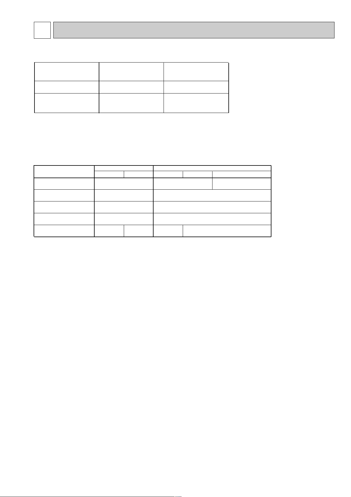
PARTS NAME
FLA
1,FLA2
FLA3
AIR FILTER
UNDER PANEL
TOP PANEL
RECEIVING UNIT
FAN GUARD
R01 12G 500
R01 12G 812
R01 12G 641
—
R01 A17 500
OC129
OC200
FLA
1,FLA2
R01 12G 500
T7W E01 812
T7W E00 641
T7W 53J 675
T7W 71J 675
FLA
—
FLA
—
T7W 53J 675
R01 24K 658
TECHNICAL CHANGE
Differences with PK-3FLA2 / PU-3VJA2 , PU-3YJA3 (OC129).
Change of the Parts No..
Refer to the parts list for the details.
3
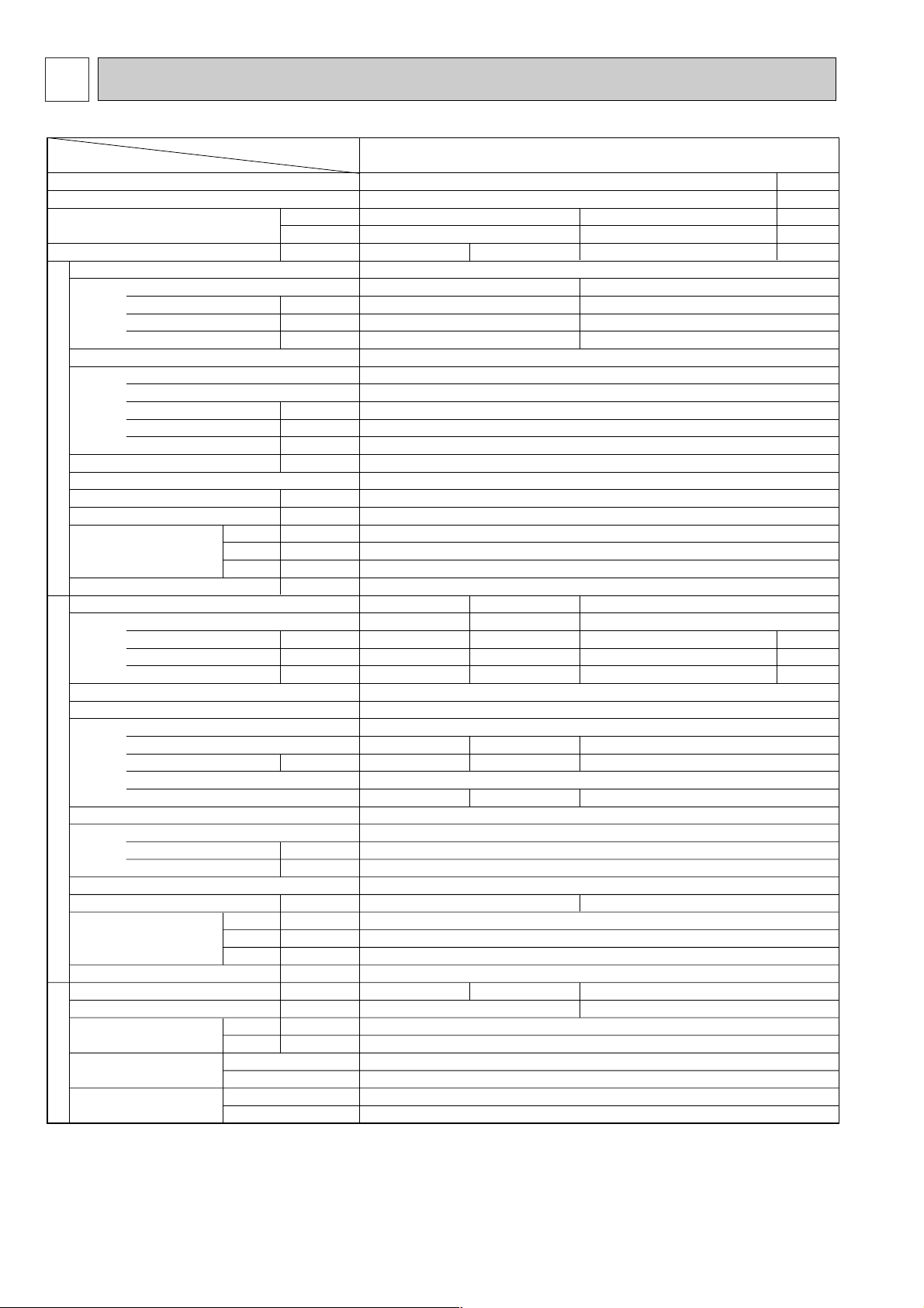
SPECIFICATIONS2
1. STANDARD SPECIFICATION
W
D
H
W
D
H
Liquid
Gas
Service Ref.
Btu/h
W
kW
kW
A(%)
A
kW
3
/min(CFM)
m
Pa,mmAq
kW
dB
mm(in.)
mm(in.)
mm(in.)
mm(in.)
kg(lbs)
kW
A(%)
A
kW
kW
3
/min(CFM)
m
dB
mm(in.)
mm(in.)
mm(in.)
kg(lbs)
W
kg(lbs)
mm(in.)
mm(in.)
27,000
7,900
3.28 / 3.30 3.28 / 3.30
Single, 50Hz, 220/240V
0.095 / 0.095
0.44 / 0.44 (98/90)
0.7 / 0.8
Munsell 3.4Y 7.7/0.8(White)
Wireless remote controller & Built-in
PU-3VJC
Single, 50Hz, 220/240V
3.18 / 3.20
15.1/13.9(96/96)
54 / 58
NH52VND
2.2
*6 *7
32 / 38 32 / 38 38
R-22 2.8(6.2)
PU-3YJC
Three, 50Hz, 380/415V
3.18 / 3.20
5.7/5.3(85/84)
34 / 37
NH52YDE
2.4
52 53
295 (+24) (11-5/8 (add 1))
Item
Indoor, Outdoor DB/WB°C
Condition
Capacity *1
Total input *1
Service Ref.
Power supply(phase, cycle,voltage)
Input
Running current (Power factor)
Starting current
External finish
Heat exchanger
Fan(drive) / No.
Fan motor output
Airflow (Low-High)
External static pressure
Booster heater
INDOOR UNIT
Operation control & Thermostat
Noise level (Low-High) *2
Unit drain pipe O.D.
Dimensions
Weight
Service Ref.
Power supply (phase, cycle, voltage)
Input
Running current /Power factor
Starting current
External finish
Refrigerant control
Compressor
Model
Motor output
Starter type
Protection devices
Heat exchanger
OUTDOOR UNIT
Defrost method
Noise level *2
Dimensions
Weight
Crankcase heater
Refrigerant Charge
Pipe size O.D.
Connection method
Between the indoor &
REFRIGERANT PIPING
outdoor units
Fan(drive) / No.
Fan motor output
Airflow
Indoor side
Outdoor side
Height difference
Piping length
w1 Refrigerant piping length (one way) : 5m (16ft)
w2 Noise level is measured in an unacoustic room based on JIS conditions.
w3 Up to 20m it is unnecessary to charge additional refrigerant.
w4 Indoor, Outdoor DB/WB : 29/19°C, 46/24°C
w5 Cooling SSA385, 386
w6 Inner thermostat, HP switch, LP switch.
w7 Thermal switch, Reversed-phase protector, HP switch, LP switch, Thermal relay.
PK-3FLA
27/19°C , 35/24°C
Cooling (JIS B8616)
PK-3FLA3
Plate fin coil
Line flow (direct) / 2
15 - 20 (530-706)
0 (direct blow)
20 (13/16)
1,400 (55-1/8)
235 (9-1/4)
340 (13-3/8)
Munsell 5Y 7/1
Capillary tube
Hermetic
Line start
Plate fin coil
Propeller (direct) / 1
50 (1765)
870 (34-1/4)
850 (33-7/16)
73 (161)
9.52 (3/8)
15.88 (5/8)
*3 Max. 20m
*3 Max. 30m
3
0.04
—
39 - 45
24 (53)
0.085
—
Flared
Flared
27,300
8,000
3.54
Single, 60Hz, 220V
0.095
0.44 (98)
0.7
PU-3NJA
Single, 60Hz, 220V
3.44
17.6(89)
80
NHJ47NAD
R-22 3.5 (7.7)
1
2.2
*6
*4
*5
23,500
6,900
4.19
4.09
20.9(89)
80
4
 Loading...