

Mitsubishi PK18FL3, PK24FL3, PK30FL3, PK36FL3 User Manual

PK18FL3
PK24FL3
PK30FL3
PK36FL3
CONTENTS
1. TECHNICAL CHANGE ··················································································OC275- 2
2. FEATURES·····································································································OC275- 3
3. PART NAME AND FUNCTIONS····································································OC275- 4
4. SPECIFICATIONS··························································································OC275- 5
5. DATA ··············································································································OC275- 6
6. OUTLINES AND DIMENSIONS ·····································································OC275-13
7. REFRIGERANT SYSTEM DIAGRAM····························································OC275-15
8. WIRING DIAGRAM························································································OC275-16
9. OPERATION FLOW-CHART·········································································OC275-17
10. MICROPROCESSOR CONTROL··································································OC275-20
11. TROUBLESHOOTING····················································································OC275-32
12. DISASSEMBLY PROCEDURE ······································································OC275-35
13. PARTS LIST···································································································OC275-38
OC275-1

1
TECHNICAL CHANGE
PK18FL1 ➔ PK18FL3
PK24FL
PK30FL
PK36FL
● REMOTE CONTROLLER has changed.
● INDOOR CONTROLLER BOARD has changed accordance with remote controller change.
1 ➔ PK24FL3
1 ➔ PK30FL3
1 ➔ PK36FL3
1) From TRANSFORMER to POWER BOARD.
2) SW1 changed from function selector to mode selector.
3) SW2 changed from unit selector to address selector.
4) The number of switches of SW3 changed from 3 to 2 pieces.
5) Function of jumper wire for JR is blotted out and SW5 for model selector, SW6 for address selector, SW7 for model
selector, SW8 for option and SW9 for model selector are added.
OC275-2
2
MODEL
SELECT
NOT AVAILABLE
SWING
CHECK
FAN
TEST
RUN
˚F
˚C
AMPMSTOP
START
FEATURES
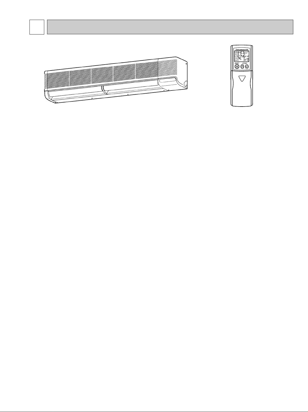
Indoor unit
Wireless Remote controller
Models Cooling capacity SEER
PK18FL3 18,500 Btu/h 11.3
PK24FL3 24,000 Btu/h 10.6
PK30FL3 30,000 Btu/h 10.7
PK36FL3 34,200 Btu/h 10.2
1. COMPACT DESIGN
The PK series models have been downsized and now require such minimal wall space that they can even be installed
above windows.
2. LCD WIRELESS REMOTE CONTROLLER
The new wireless remote controller has a larger easy-to-read temperature display, and executes ON/OFF commands
and temperature settings with a press of the button.
3. AUTO FLAP SHUTTER
With a simple flick of the OFF switch the air outlet can be closed off with a shutter. The shutter also functions as a flap
during operation to adjust the air flow angle, with “Auto Angle 1” securing a comfortable air flow.
4. INSTALLATION : FAST AND EASILY ADAPTABLE
(1) Multi-directional piping
Multi directional drain and refrigerant piping radically improves flexibility in selecting installation layouts.
PK18/24/30/36FL3 models boast refrigerant piping in 4 directions and drain piping in 2 directions.
(2) Back plate installation guide
The back plate installation guide gives clear instructions on installation positions. The enlarged back plate secures the
unit firmly to the wall, while the support piece which lifts the unit makes left side piping work much easier.
(3) Easily removable filter and convenient wireless remote controller
The presence of thumb screws on the filters means that the filters can be quickly and smoothly removed.
5. HIGH RELIABILITY AND EASY SERVICING
In addition to the self-diagnostic function, units are also equipped with a 3-minute time delay mechanism (cooling), an auto
restart function, an emergency operation function, a test run switch, etc., to assure high reliability and easy servicing.
6. NITROGEN GAS IS CHARGED TO INDOOR UNIT
Indoor unit and refrigerant pipes are charged with nitrogen gas (N2) instead of R22 before shipment from the factory.
OC275-3
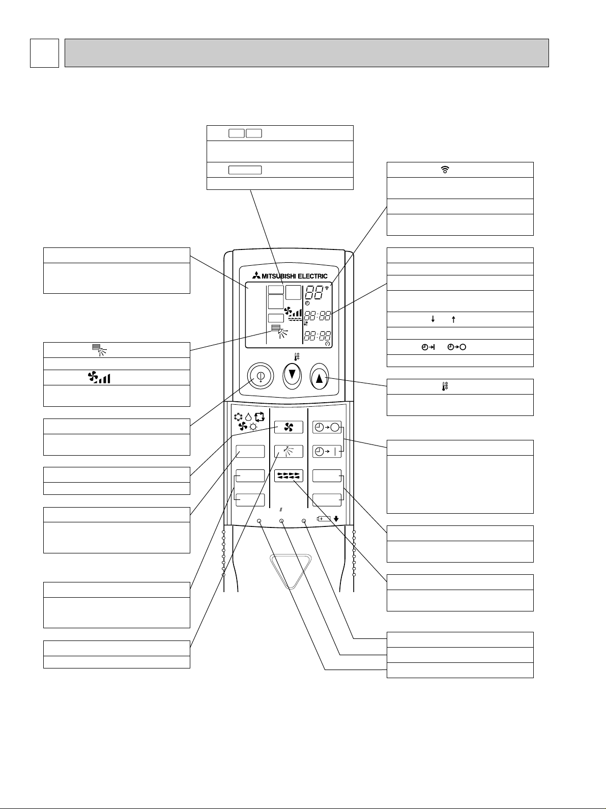
3 PART NAME AND FUNCTIONS
ON/OFF TEMP
FAN
VANE
TEST RUN
AUTO STOP
AUTO START
h
min
LOUVER
MODE
CHECK
RESETSET CLOCK
MODEL
SELECT
NOT AVAILABLE
SWING
CHECK
FAN
TEST
RUN
˚F
˚C
AMPMSTOP
START
AMPM
COOL
DRY
AUTO
FAN
HEAT
VANE CONTROL button
Used to change the air flow direction.
CLOCK button
RESET button
SET button
ON/OFF button
The unit is turned ON and OFF alternately
each time the button is pressed.
LOUVER button
This switch the horizontal fan motion ON
and OFF.
(Not available for this model.)
MODE SELECT button
Used to switch the operation mode between
cooling, drying, fan.
CHECK-TEST RUN button
Only press this button to perform an inspection check or test operation.
Do not use it for normal operation.
FAN SPEED SELECT button
Used to change the fan speed.
TIMER display
Displays when in timer operation or when
setting timer.
button
SET TEMPERATURE button sets any desired
room temperature.
CLOCK display
Displays the current time.
“ ” “ ” display
Displays the order of timer operation.
“ ” “ ” display
Displays whether timer is on or off.
Buttons used to set the “hour and minute” of
the current time and timer settings.
h and min buttons
88°F display
SET TEMP. display indicates desired temperature set.
display
FAN SPEED display indicates which fan
speed has been selected.
display
The vertical direction of air flow is indicated.
display
Blinks when model is selected.
display
Lights up while transmission to the indoor
unit is mode using switches.
display
CHECK&TEST RUN display indicates that
the unit is being checked or test-run.
OPERATION MODE display
OPERATION MODE display
Operation mode display indicates which operation mode is in effect.
TIMER CONTROL buttons
AUTO STOP (OFF timer): when this switch
is set, the air conditioner will be automatically stopped at the preset time.
AUTO START (ON timer): when this switch
is set, the air conditioner will be automatically started at the preset time.
MODEL SELECT
CHECK
TEST RUN
●Wireless remote controller
● When cover is open.
OC275-4
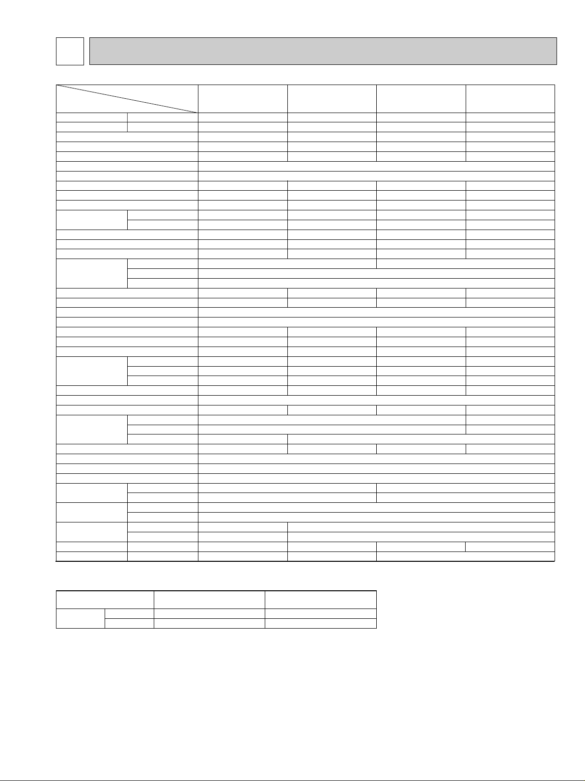
SPECIFICATIONS4
Capacity
Power consumption
EER
SEER
INDOOR UNIT MODEL
External finish
Power supply
Max. fuse size (time delay)
Min ampacity
Fan motor
Airflow Hi-Lo
Moisture removal
Sound level Hi-Lo
Unit drain pipe I.D.
Dimensions
Weight
OUTDOOR UNIT MODEL
External finish
Power supply
Max. fuse size (time delay)
Min. ampacity
Fan motor
Compressor
Crankcase heater
Refrigerant control
Sound level
Dimensions
Weight
REMOTE CONTROLLER
Control voltage (by built-in transformer)
REFRIGERANT PIPING
Pipe size
Connection method
Between the indoor
& outdoor units
Refrigerant charge
Refrigerant oil
❈ 1
❈ 1
❈ 1
Dry
Wet
W
D
H
Model
W
D
H
Liquid
Gas
Indoors
Outdoors
Height
Piping length
Btu/h
kW
V, Phase, Hz
A
A
F.L.A.
CFM
CFM
Pints/h
dB
in.
in.
in.
in.
Ib.
V, Phase, Hz
A
A
F.L.A
R.L.A
L.R.A
A(W)
dB
in.
in.
in.
Ib.
in.
in.
ft
fr
–
cc <Model>
Model
130
130
5 lbs 8 oz
520 <MS-56>
PK18FL3
18,500
1.75
10.6
11.3
PK18FL3
15
1
0.7
710-530
640-480
5.3
48-41
1-1/16
53
PU18EK
1
20
16
0.75
RH247NAB
12.0
37
0.11/0.12 (23/28)
53
33-1/2
154
55-1/8
34-1/4
11-5/8
PK24FL3
24,000
2.34
10.3
10.6
PK24FL3
15
1
0.7
710-530
640-480
7.2
48-41
1-1/16
53
PU24EK
1
20
16
0.65+0.65
NH33NBD
11.5
54
0.16/0.17 (33/39)
55
207
Munsell 3.4Y7.7/0.8
115, 1, 60
9-1/4
13-3/8
Munsell 5Y7/1
208/230, 1, 60
Capillary tube
With indoor unit
Indoor unit - outdoor unit : DC12V
Not supplied (optional parts)
Flared
Flared
PK30FL3
30,000
3.06
9.8
10.7
PK30FL3
15
2
1.0
990-780
890-700
9.6
49-44
1-1/16
62
PU30EK
1
30
20
0.65+0.65
NH41NAD
14.0
73
0.16/0.17 (33/39)
55
49-9/16
208
164
164
10 lbs 2 oz
1/2
3/4
PK36FL3
34,200
3.47
9.9
10.2
PK36FL3
15
2
1.0
990-780
890-700
10.5
49-44
1-1/16
62
PU36EK
1
30
22
0.75+0.75
NH47NAD
17.5
87
0.16/0.17 (33/39)
55
38-3/16
13-9/16
220
66-5/32
Item
NOTES : ❈ 1.Rating conditions —indoor : 80˚FDB, 67˚FWB outdoor : 95˚FDB,75˚FWB.
Operating range
Indoor intake air temperature
DB 95˚F, WB 71˚F
DB 67˚F, WB 57˚F
Outdoor intake air temperature
DB 115˚F
DB 0˚F *
Cooling
Maximum
Minimum
3/8
5/8
9 lbs 15 oz
1200 <MS32N-1>
10 lbs 9 oz
1300 <MS32N-1>
*
In case of the wind baffle is installed.
(In case of the wind baffle is not installed, the minimum temperature will be DB 23˚F.)
OC275-5
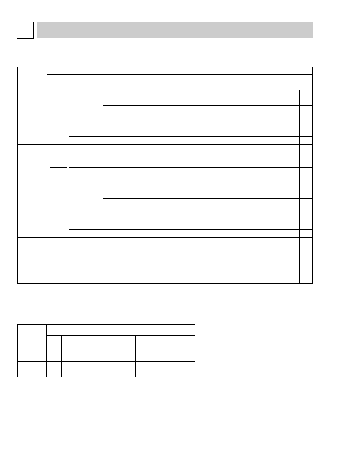
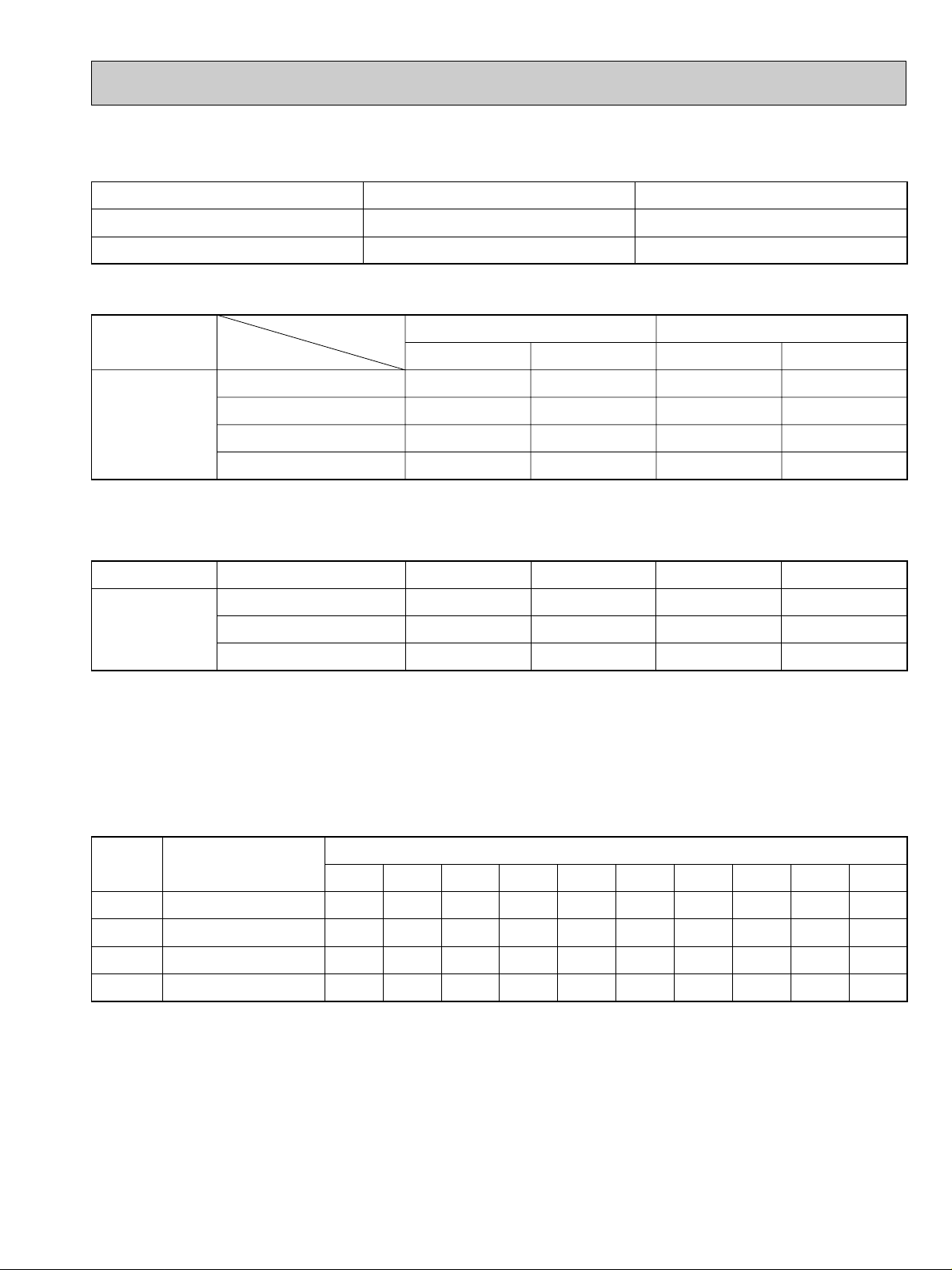
5 DATA
Notes 1. B.F. : Bypass Factor, IWB : Intake air wet-bulb temperature
TC : Total Capacity (x10
3
Btu/h), SHC : Sensible Heat Capacity (x10
3
Btu/h)
TPC : Total Power Consumption (kW)
2. Cooling capacity correction factors and Refrigerant piping length (one way) range.
MODEL
Refrigerant piping length (one way)
PK18FL3
PK24FL3
PK30FL3
PK36FL3
1.0
1.0
1.0
1.0
25ft
0.992
0.981
0.981
0.981
40ft
0.983
0.968
0.968
0.968
55ft
0.978
0.952
0.952
0.952
70ft
0.966
0.940
0.940
0.940
85ft
0.959
0.925
0.925
0.925
100ft
0.950
0.913
0.913
0.913
115ft
0.945
0.900
0.900
0.900
130ft
—
0.886
0.886
0.886
150ft
—
0.874
0.874
0.874
164ft
TC
21.5
20.1
18.8
18.6
17.8
17.4
27.9
26.1
24.3
24.1
23.0
22.6
34.9
32.6
30.4
30.2
28.8
28.3
39.8
37.1
34.7
34.4
32.8
32.2
IWB
(˚F)
71
67
63
62.5
60
59
71
67
63
62.5
60
59
71
67
63
62.5
60
59
71
67
63
62.5
60
59
Indoor air
Airflow
(CFM)
B.F
Models
PK18FL3
PK24FL3
PK30FL3
PK36FL3
710
0.14
710
0.14
990
0.15
990
0.15
DB 80˚F
DB75˚F(50%RH)
DB72˚F(50%RH)
DB70˚F(50%RH)
DB 80˚F
DB75˚F(50%RH)
DB72˚F(50%RH)
DB70˚F(50%RH)
DB 80˚F
DB75˚F(50%RH)
DB72˚F(50%RH)
DB70˚F(50%RH)
DB 80˚F
DB75˚F(50%RH)
DB72˚F(50%RH)
DB70˚F(50%RH)
75
SHC
14.8
16.5
17.9
16.0
15.6
15.0
16.4
18.8
20.7
18.3
17.8
17.3
21.5
24.5
26.9
23.8
23.2
22.5
23.0
26.3
29.3
25.8
25.1
24.3
TPC
1.52
1.49
1.46
1.45
1.43
1.43
2.04
1.99
1.95
1.94
1.92
1.91
2.66
2.61
2.55
2.54
2.51
2.49
3.02
2.96
2.89
2.88
2.84
2.83
TC
20.8
19.3
18.0
17.9
17.1
16.7
26.9
25.1
23.4
23.2
22.1
21.7
33.7
31.4
29.2
29.0
27.7
27.1
38.4
35.7
33.3
33.1
31.5
30.9
85
SHC
14.3
15.8
17.2
15.4
15.0
14.4
15.8
18.1
20.0
17.6
17.1
16.6
20.8
23.6
25.8
22.9
22.3
21.5
22.1
25.3
28.1
24.8
24.1
23.3
TPC
1.65
1.61
1.57
1.57
1.55
1.54
2.21
2.16
2.11
2.10
2.07
2.05
2.89
2.82
2.75
2.75
2.70
2.69
3.28
3.20
3.12
3.11
3.07
3.05
TC
19.9
18.5
17.2
17.1
16.3
16.0
25.8
24.0
22.4
22.2
21.1
20.7
32.3
30.0
27.9
27.7
26.4
25.9
36.8
34.2
31.9
31.6
30.1
29.5
Outdoor intake air DB temperature (˚F
)
95
SHC
13.7
15.2
16.4
14.7
14.3
13.8
15.1
17.3
19.1
16.8
16.4
15.8
19.9
22.5
24.6
21.9
21.3
20.6
21.2
24.3
26.9
23.7
23.0
22.3
TPC
1.80
1.75
1.70
1.70
1.67
1.66
2.40
2.34
2.28
2.27
2.23
2.22
3.14
3.06
2.98
2.97
2.92
2.90
3.57
3.47
3.38
3.37
3.31
3.29
TC
19.0
17.6
16.4
16.2
15.5
15.1
24.6
22.9
21.3
21.1
20.0
19.6
30.8
28.6
26.6
26.3
25.1
24.6
35.1
32.6
30.3
30.0
28.6
28.0
105
SHC
13.0
14.4
15.6
13.9
13.6
13.1
14.4
16.5
18.2
16.0
15.5
15.0
19.0
21.5
23.5
20.7
20.2
19.5
20.2
23.1
25.6
22.5
21.9
21.1
TPC
1.95
1.89
1.83
1.83
1.79
1.78
2.61
2.53
2.45
2.44
2.40
2.38
3.41
3.30
3.21
3.20
3.14
3.11
3.87
3.74
3.64
3.63
3.56
3.53
TC
18.1
16.7
15.5
15.4
14.6
14.3
23.4
21.7
20.1
19.9
18.9
18.5
29.3
27.1
25.1
24.9
23.7
23.2
33.4
30.9
28.7
28.4
27.0
26.4
115
SHC
12.4
13.7
14.8
13.2
12.8
12.4
13.7
15.6
17.2
15.1
14.7
14.1
18.1
20.3
22.2
19.6
19.1
18.4
19.3
21.9
24.2
21.3
20.7
19.9
TPC
2.10
2.03
1.96
1.96
1.92
1.90
2.81
2.71
2.62
2.62
2.56
2.54
3.68
3.54
3.43
3.42
3.35
3.32
4.17
4.02
3.89
3.88
3.80
3.77
1. PERFORMANCE DATA
1) COOLING CAPACITY
2) COOLING CAPACITY CORRECTIONS
OC275-6
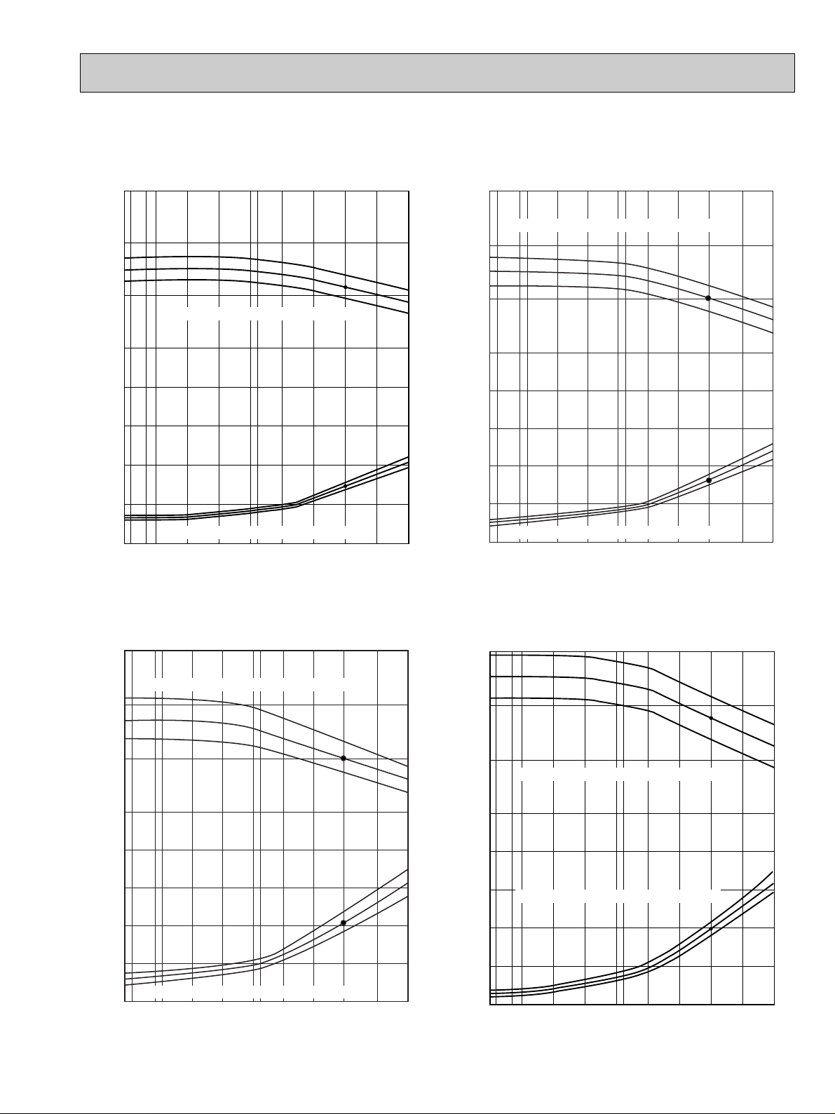
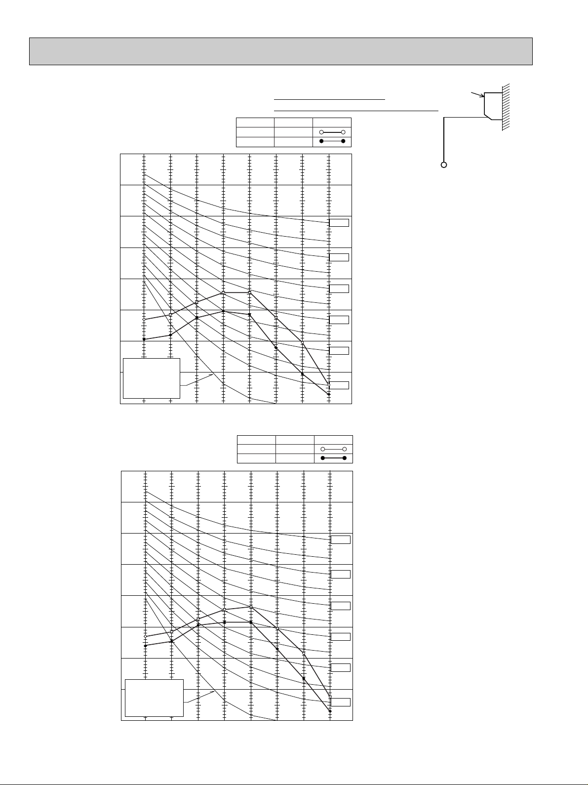
2. PERFORMANCE CURVE
30
71
67
63
71
67
63
18
24
12
3.0
2.5
2.0
1.5
1.0
023 3235
45 55
65(67)
75 85 95 105 115
Total capacity (✕10
3
Btu/h)Total power consumption (kW)
Outdoor intake air DB temperature (°F)
indoor intake air WB temperature (°F)
indoor intake air WB temperature (°F)
SHF=0.82
Total capacity (✕10
3
Btu/h)Total power consumption (kW)
Outdoor intake air DB temperature (°F)
023 3235
45
65 (67)
75 85 95 105 11555
1.5
2.0
2.5
3.0
3.5
18
36
24
30
71
67
63
71
67
63
indoor intake air WB temperature (°F)
indoor intake air WB temperature (°F)
SHF=0.72
023 3235
45
65 (67)
75 85 95 105 11555
2.0
2.5
3.0
3.5
4.0
24
42
30
36
71
67
63
71
67
63
Total capacity (✕10
3
Btu/h)Total power consumption (kW)
Outdoor intake air DB temperature (°F)
indoor intake air WB temperature (°F)
indoor intake air WB temperature (°F)
SHF=0.75
NOTE : Apoint on the curve shows the reference point.
PK18FL3 COOLING CAPACITY PK24FL3 COOLING CAPACITY
PK30FL3 COOLING CAPACITY PK36FL3 COOLING CAPACITY
OC275-7
42
Btu/h)Total power consumption (kW)
3
36
30
indoor intake air WB temperature (°F)
Total capacity (✕10
24
4.5
4.0
3.5
3.0
2.5
indoor intake air WB temperature (°F)
023 3235
45 55
Outdoor intake air DB temperature (°F)
65(67) 75
SHF=0.71
71
67
63
71
67
63
85 95 105 115
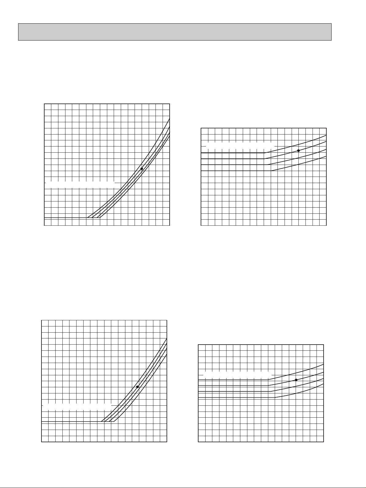
Data is based on the condition under indoor humidity 50%.
PK18FL3
<Cooling mode>
PK18FL3
86
80
75
70
86
80
75
70
Outdoor ambient temperature
30 40 50 60 70 80 90 100 110
360
350
340
330
320
310
300
290
280
270
260
250
240
230
220
210
200
190
180
170
160
[psi.G]
100
90
80
70
60
50
40
30
20
30 40 50 60 70 80 90 100 110
Outdoor ambient temperature
DB(°F)
DB(°F)
[psi.G]
Indoor DB temperature (°F)
Indoor DB temperature (°F)
Condensing pressure
Suction pressure
PK24FL3
<Cooling mode>
PK24FL3
Outdoor ambient temperature
Outdoor ambient temperature
DB(°F)
DB(°F)
86
80
75
70
86
80
75
70
30 40 50 60 70 80 90 100 110
350
340
330
320
310
300
290
280
270
260
250
240
230
220
210
200
190
180
170
160
150
[psi.G]
100
90
80
70
60
50
40
30
20
30 40 50 60 70 80 90 100 110
[psi.G]
Indoor DB temperature (°F)
Indoor DB temperature (°F)
Condensing pressure
Suction pressure
Air flow should be set at HI.
A point on the curve shows the reference point.
OC275-8
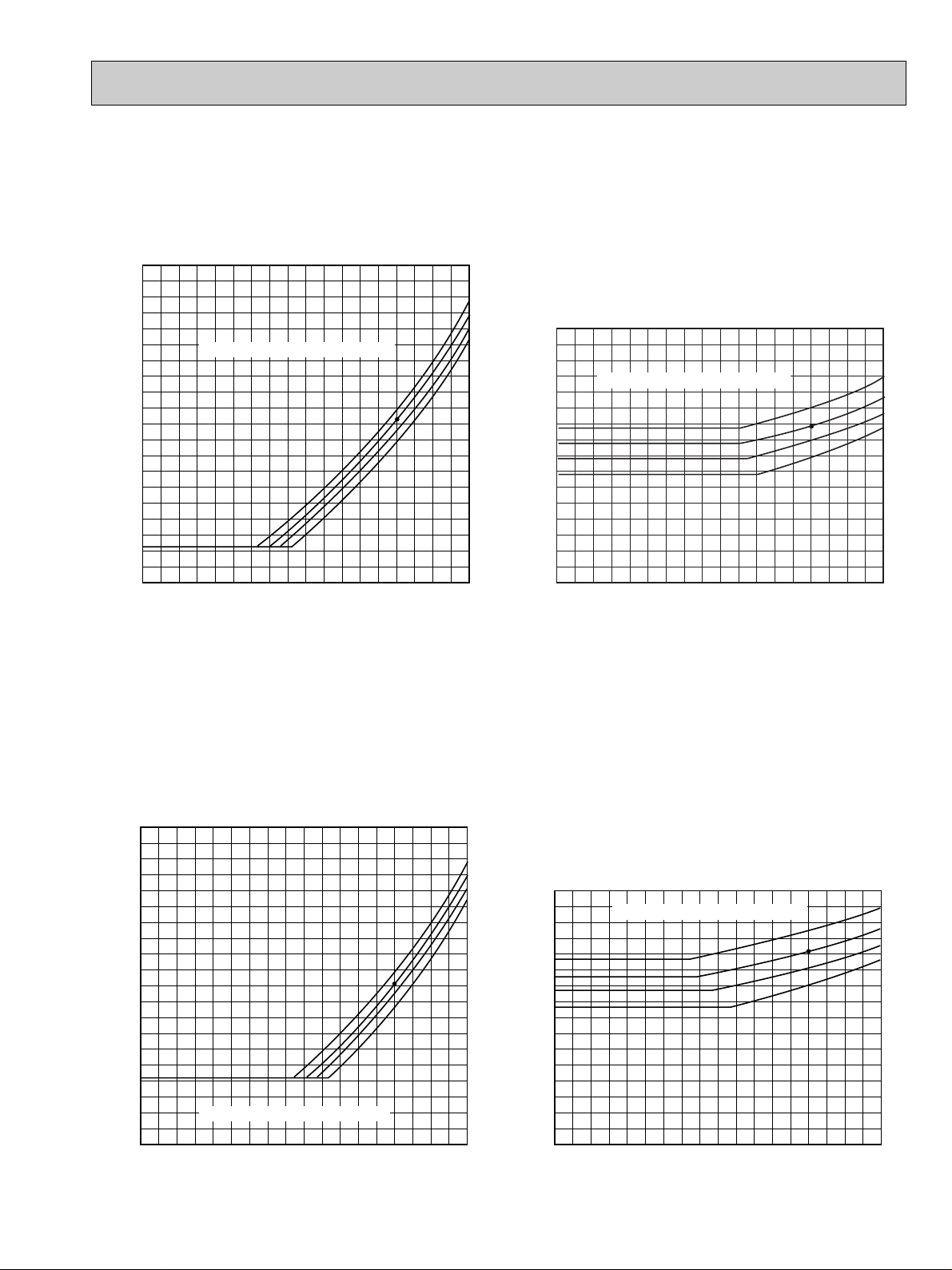
Data is based on the condition under indoor humidity 50%.
Outdoor ambient temperature (°F)
Indoor DB temperature (°F)
[psi. G]
340
330
320
310
300
290
280
270
260
250
240
230
220
210
200
190
180
170
160
150
140
86
80
75
70
PK30FL3
<Cooling mode>
Condensing pressure
30 40 50 60 70 80 90 100 110
DB(°F)
Outdoor ambient temperature (°F)
PK30FL3
Suction pressure
DB(°F)
86
80
75
70
100
90
80
70
60
50
40
30
30 40 50 60 70 80 90 100 110
[psi.G]
Indoor DB temperature (°F)
Outdoor ambient temperature (°F)
Indoor DB temperature (°F)
[psi. G]
340
330
320
310
300
290
280
270
260
250
240
230
220
210
200
190
180
170
160
150
140
86
80
75
70
PK36FL3
<Cooling mode>
Condensing pressure
30 40 50 60 70 80 90 100 110
DB(°F)
Outdoor ambient temperature (°F)
Indoor DB temperature (°F)
[psi. G]
90
80
70
60
50
40
30
20
86
80
75
70
PK36FL3
Suction pressure
30 40 50 60 70 80 90 100 110
DB(°F)
Air flow should be set at HI.
A point on the curve shows the reference point.
OC275-9
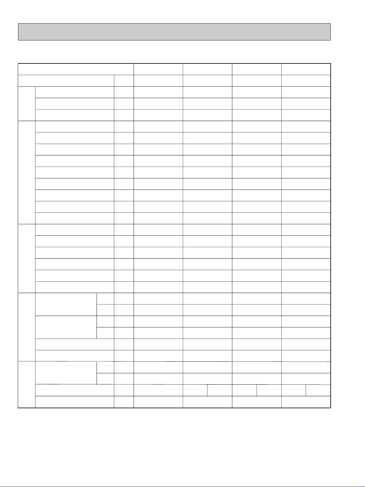
3. STANDARD OPERATION DATA
750 750
750
750 760 760
Capacity
SHF
Input
INDOOR UNIT MODEL
Power supply (V, phase, Hz)
Input
Fan current
OUTDOOR UNIT MODEL
Power supply (V, phase, Hz)
Input
Comp. current
Fan current
Condensing pressure
Suction pressure
Discharge temp.
Condensing temp.
Suction temp.
Ref. pipe length
Intake air temperature
Discharge air temperature
Fan speed (High)
Airflow (High)
Intake air temperature
Fan speed upper / lower
Airflow
Unit
Btu / h
—
kW
kW
A
kW
A
A
psi-G
psi-G
˚F
˚F
˚F
ft
˚F
˚F
˚F
˚F
rpm
CFM
˚F
˚F
rpm
CFM
PK18FL3
Cooling
18,500
0.82
1.75
PK18FL3
115, 1, 60
0.09
0.7
PU18EK
1
208/230, 1, 60
1.66
12.0
0.75
255
82
171
118
51
25
80
67
61
59
1,300
710
95
75
790
1,590
PK24FL3
Cooling
24,000
0.72
2.34
PK24FL3
115, 1, 60
0.09
0.7
PU24EK
1
208/230, 1, 60
2.25
11.5
0.65+0.65
240
74
155
114
44
25
80
67
58
56
1,300
710
95
75
3,170
PK30FL3
Cooling
30,000
0.75
3.06
PK30FL3
115, 1, 60
0.12
1.0
PU30EK
1
208/230, 1, 60
2.94
14.0
0.65+0.65
247
77
163
116
46
25
80
67
59
58
1,380
990
95
75
3,170
PK36FL3
Cooling
34,200
0.71
3.47
PK36FL3
115, 1, 60
0.12
1.0
PU36EK
1
208/230, 1, 60
3.35
17.5
0.75+0.75
247
73
163
116
43
25
80
67
58
56
1,380
990
95
75
3,350
DB
WB
DB
WB
DB
WB
Item
Model
TotalRefrigerant circuitIndoor sideOutdoor side Electrical circuit
OC275-10
4. OPERATING RANGE
Indoor unit
Outdoor unit
Rating
115V 1 phase 60Hz
208/230V 1 phase 60Hz
Allowable voltage
Min. 103V — Max. 127V
Min. 198V — Max. 253V
Function
Cooling
DB (˚F)
80
95
67
80
Condition
Standard temperature
Maximum temperature
Minimum temperature
Maximum humidity
Indoor
Intake air temperature
Outdoor
WB (˚F)
67
71
57
75
DB (˚F)
95
115
0
80
WB (˚F)
75
75
—
75
Airflow
Air speed
Coverage range
(CFM)
(ft / sec.)
(ft)
Standard
height
(8.2ft)
PK18FL3
710
16.1
41
PK24FL3
710
16.1
41
PK30FL3
990
17.7
50
PK36FL3
990
17.7
50
Model
PK18FL3
PK24FL3
PK30FL3
PK36FL3
5 lbs 8 oz
9 lbs 15 oz
10 lbs 2 oz
10 lbs 9 oz
25ft
0
0
0
0
40ft
0
0
0
0
55ft
0
0
0
0
70ft
0
0
0
0
85ft
0
0
0
0
100ft
0
0
0
0
115ft
2
2
5
5
130ft
4
4
10
10
150ft
—
7
16
16
164ft
—
9
20
20
Outdoor unit
precharged
(up to 100ft)
Refrigerant piping length (over way)
1) POWER SUPPLY
2) OPERATION
5. OUTLET AIR SPEED AND COVERAGE RANGE
● The air coverage range is the value up to the position where the air speed is 0.8ft/sec. when air is blown out
horizontally from the unit at the High fan setting.
The coverage range should be used only as a general guideline since it varies according to the size of the
room and furniture installed inside the room.
6. ADDITIONAL REFRIGERANT CHARGE (R22 (OZ))
OC275-11
7. NOISE CRITERION CURVES
90
80
70
60
50
40
30
20
10
63 125 250 500 1000 2000 4000 8000
APPROXIMATE
THRESHOLD OF
HEARING FOR
CONTINUOUS
NOISE
NC-60
NC-50
NC-40
NC-30
NC-20
NC-70
OCTAVE BAND SOUND PRESSURE LEVEL, dB re 0.0002 MICRO BAR
BAND CENTER FREQUENCIES, Hz
PK18FL3
PK24FL3
Hi
NOTCH
Lo
48
SPL(dB)41LINE
Wall
Unit
3.3ft
3.3ft
Ambient temperature 80˚F
Test conditions are based on JIS Z8731
PK30FL3
NOTCH
PK36FL3
90
80
70
60
50
40
30
APPROXIMATE
20
THRESHOLD OF
HEARING FOR
CONTINUOUS
NOISE
OCTAVE BAND SOUND PRESSURE LEVEL, dB re 0.0002 MICRO BAR
10
63 125 250 500 1000 2000 4000 8000
BAND CENTER FREQUENCIES, Hz
SPL(dB)44LINE
Hi
Lo
OC275-12
49
NC-70
NC-60
NC-50
NC-40
NC-30
NC-20
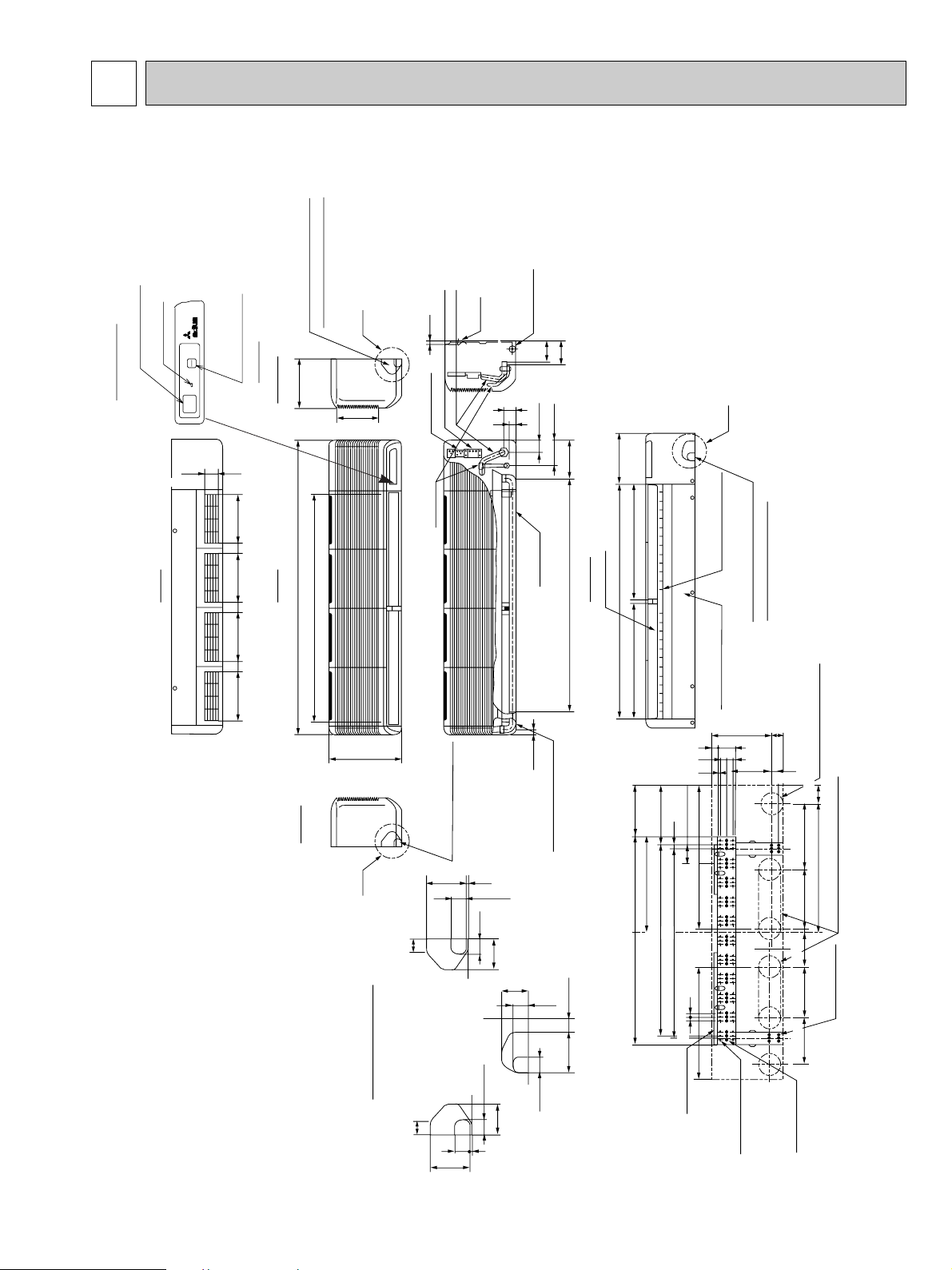
6
9-1/4
1-25/32
9-1/4
1-25/32
9-1/4 9-1/4
1-25/32
1/2
13-3/8
7-3/4
1-21/32
2-9/32
Top
Front
Right side
Left side
55-1/8
42-15/16
Air intake
9-1/4
C
Knock out hole for right piping
Refrigerant pipe. Drain pipe
Knock out hole for
left piping
Drain hose for
left-hand side piping
Drain hose
Bottom
Auto vane
(Gas pipe)
Drain hose
Bolt
Gas pipe
19/32
Terminal block for power supply
Terminal block for control
(Liquid pipe)
Liquid pipe 3/8F
Gas pipe 5/8F
Liquid pipe
A
1-3/16
1-15/32
1-17/32
3-27/32 2-9/16
2-29/32
5/32
3-15/16
1-17/32
1-3/16
1-15/32
2-29/32
5/32
1-5/32
11-1/32
1-3/16
7-1/4
1-3/16
3-5/32
1-3/18
2-3/8
13/32
1-17/32
1-15/32
2-9/16
3-15/16
A
B
C
Knock out hole for piping
31/32
43-11/16
7-7/32
9-7/16
B
44-3/32
21-23/32
4-23/32
2-5/32
4-1/32
4-3/8
Air outlet
21-23/32
Air outlet
Change vane (manual)
Under panel
Removable at left-hand
side piping
Knock out hole for under-piping
Refrigerant pipe. Drain pipe
Rear piping opening
Range for left rear piping opening
12-{1/4 Hole for
tapping screw
66-{1/4 hole for
tapping screw
Wall fixture
Unit center
32-{15/32
hole for bolt
23/32
3-19/32
35-7/16
38-31/32
17-29/32
11-7/32
9-21/32
3/4
9-7/16 11-1/32 12-3/8
24
Drainage range
on left-hand side
Drainage range
on right-hand side
10x3-19/32=(35-13/16)
7-3/32
8-27/32
23/32
3-17/32
2-15/32
ELECTRICELECTRICELECTRICELECTRICELECTRIC
MITSUBISHI
MITSUBISHI
MITSUBISHI
MITSUBISHI
MITSUBISHI
Emergency switch
(Cool)
Display section
Receiving section
Power lamp
ON
ON
OFF
POWER
OUTLINES AND DIMENSIONS
5.1. Indoor Unit
PK18FL3
PK24FL3
Unit : inch
OC275-13
 Loading...