

Mitsubishi Electric PHV1000DXE HO, PHV1500DXE LO, PHV1500DXE HO, PHV2000DXE LO, PHV2000DXE HO Maintance Manual

9901025-2 Page 1 of 21
PHV HEAT PUMP RANGE AIR CURTAINS
INSTALLATION, OPERATION & MAINTENANCE INSTRUCTIONS
For use with Mr Slim units
PLEASE READ THESE INSTRUCTIONS CAREFULLY BEFORE ATTEMPTI NG INSTALLATION
Thermoscreens Ltd
St. Mary’s Road Nuneaton
Warwickshire England
CV11 5AU
Email: sales@thermoscreens.com
Tel: +44 (0) 24 7638 4646
Fax: +44 (0) 24 7638 8578
www.thermoscreens.com
English
9901025-2 Page 2 of 21
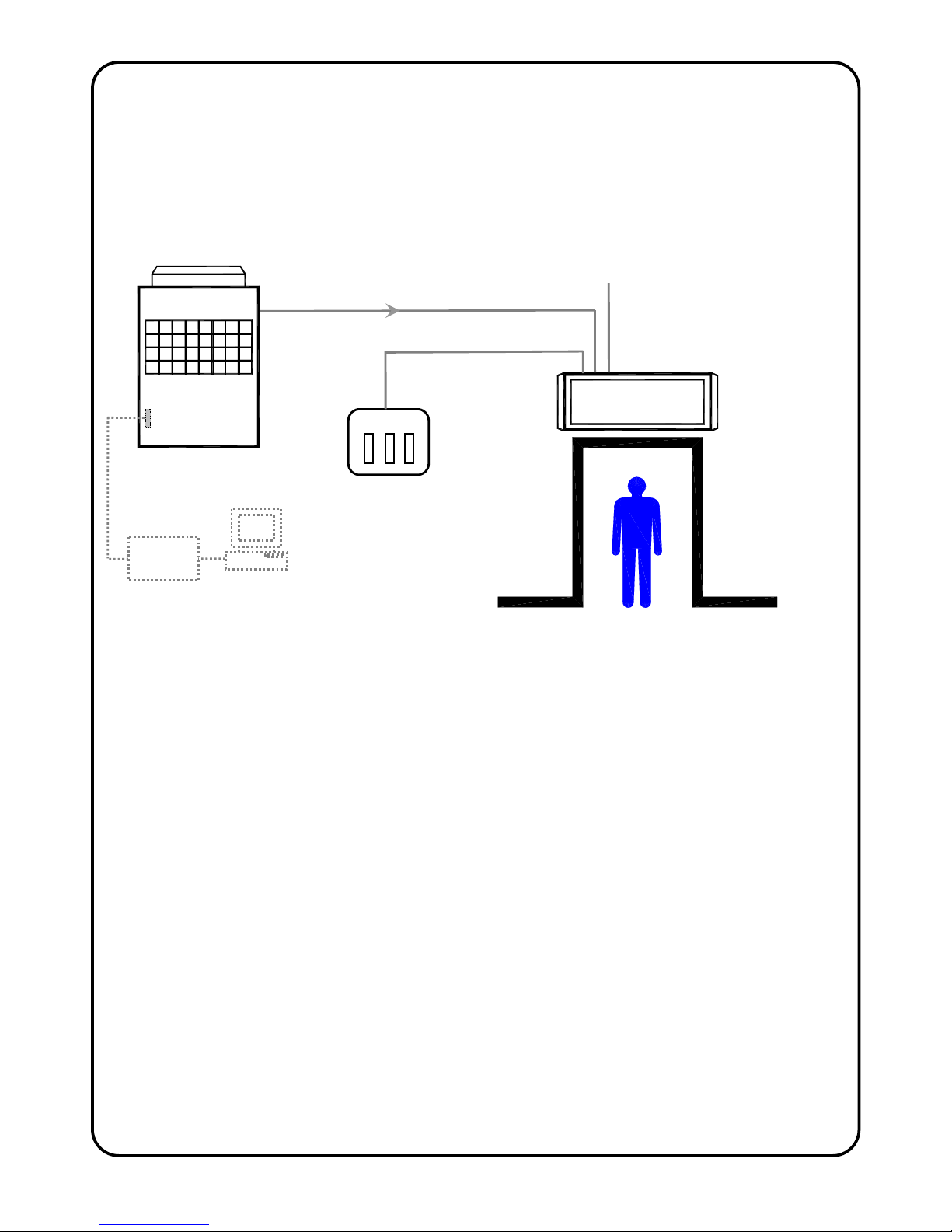
Thermoscreens / Mitsubishi Electric
Heat Pump Warm Air Curtain System
The Heat Pump Warm Air Curtain System consists of :-
• a Thermoscreens 'PHV Air Curtain' fitted with a PAC-IF010 Mitsubishi Electric Interface
PCB
• a Mitsubishi Electric 'Mr Slim Outdoor Unit'
• a Thermoscreens 'Manual Room Control' for the manual control option by the occupant
Refer to Mitsubishi Electric if the air curtain is to be controlled via a Building Management
System (BMS) or Centralised Controller. Do not install Manual Room Control and
BMS/Centralised Control components together, install either one or the other.
A communications link is supplied to the Thermoscreens Heat Pump Air Curtain from the
Mitsubishi Electric Outdoor Unit. This link provides control of the heat output of the air curtain
and tells the air curtain when the outdoor unit is in defrost mode so auxiliary electric element
heaters (if specified) can provide partial heat back-up during the few minutes of defrost.
The Air Curtain requires a permanent 3 phase electrical supply (3L+N+E) from a local
switched spur to provide power to the defrost cycle electric heating elements, the air curtain
fans and the Mitsubishi Electric Interface PCB. If the defrost cycle electric elements are not
required they can be permanently disconnected, see 'Electrical Connections', and a 1 phase
electrical supply (1L+N+E) used instead.
High and Low Output in this document refers to the heat pump heating capacity of the Air
Curtain, not to any electrical rating.
Heat Pump
Air Curtain
Mitsubishi Electric
Outdoor Unit
Communications Link
Permanent mains electrical supply
(from local switched spur) for
x Fans
x Mitsubishi Electric Interface PCB
x Defrost electric heaters (if used)
Manual Room
Control
Manual On/Off Control and
Heat Setting Control
Optional
BMS Control
Interface Board
Procon
A
32/M
9901025-2 Page 3 of 21
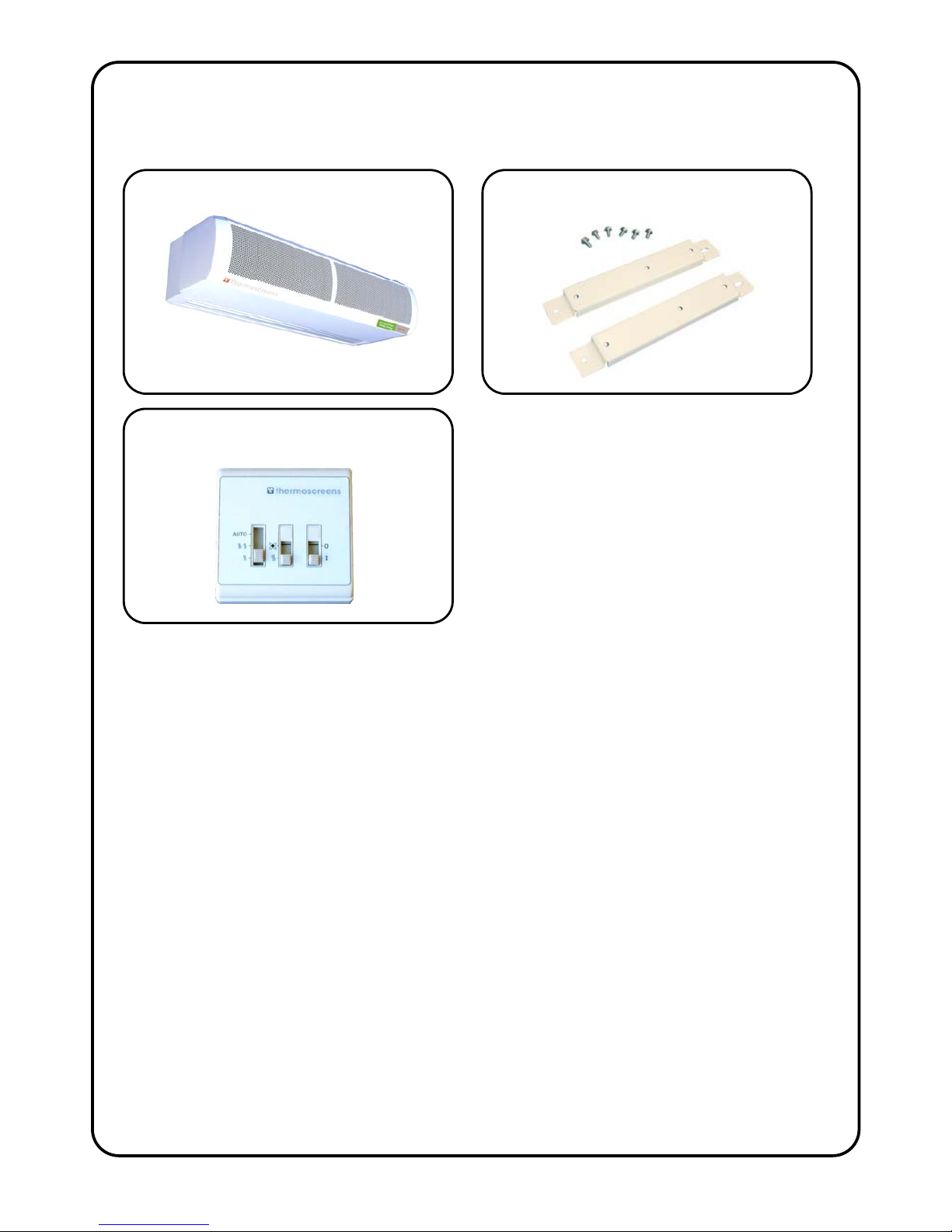
UNPACKING THE PHV HEAT PUMP AIR CURTAIN
The following items are supplied and packaged within the air curtain box.
There will also be a 'Mr Slim Outdoor Unit' supplied by Mitsubishi Electric.
The complete Thermoscreens/Mitsubishi Electric heat pump system, to provide a heat
pump warm air curtain over a doorway, including wiring, fridge pipework, etc. is to be
installed only by an approved Mitsubishi Electric refrigeration contractor.
For your records
Date of Purchase……………………………..
Place of Purchase…………………………….
Serial Number…………………………………
For warranty purposes proof of purchase is necessary so please keep a copy of your
invoice.
IMPORTANT
This Heat Pump Air Curtain in intended only for use with a Mitsubishi Electric Mr Slim
Outdoor Unit, for use on R410a with a condensing temperature of 49°C.
These instructions must be read in conjunction with the Mitsubishi Electric Mr Slim
Outdoor Unit instructions.
(All documentation supplied with each unit should be stored and kept for future reference.)
Wall Brackets and Fixing Bolts
PHV Heat Pump Air Curtain
Please note end caps are supplied loose
to be fitted during installation
Manual Room Control
If anything is missing or damaged
please contact your place of
purchase immediately.
9901025-2 Page 4 of 21
INSTALLATION OF THE HEAT PUMP AIR CURTAIN
The air curtain has been designed to be surface mounted inside of the building and
located horizontally over a doorway. It must not be installed outside of the building,
or built into a cabinet or recessed in anyway. The air curtain is intended for use as a
heating only unit.
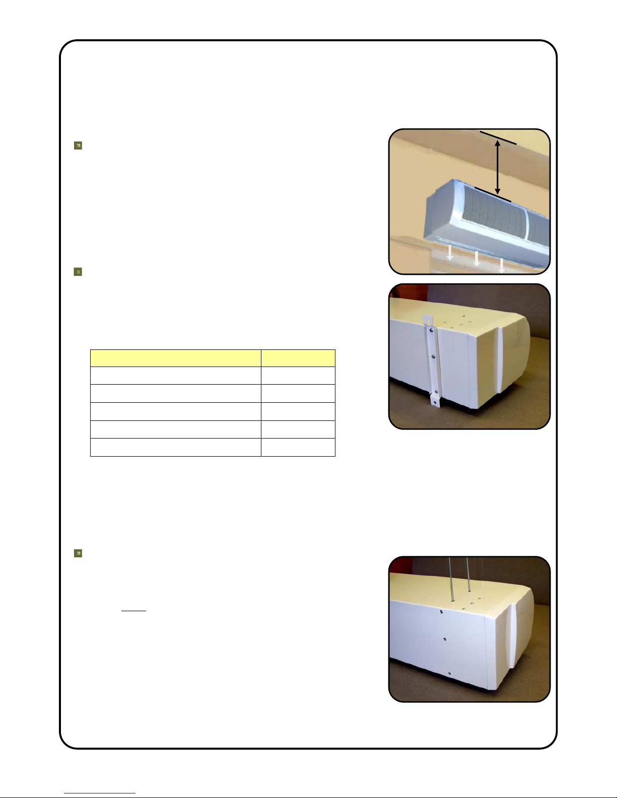
Location
The air curtain must be mounted so the discharge grille is
between 1.8m minimum and 3.75m maximum above floor
level and situated as close to the doorway as possible.
Leave a gap of 250mm minimum above the air curtain to
allow for pipework brazing operations. Beware of doorway
top edges, structural beams, door opening/closure
devices, etc. which may interfere with the air stream and
affect the location of the unit.
Wall Fixing
Bolt all of the wall brackets supplied to the rear face of the
unit as shown in the adjacent picture using the M6 bolts
supplied. Suitable wall fixing bolts (not supplied) need to
be used to fix the brackets to the wall, taking into account
the type of wall and the weight of the unit*, see table:
Air Curtain Weight (kg)
PHV1000DXE HO 39
PHV1500DXE LO 59
PHV1500DXE HO 60
PHV2000DXE LO 78
PHV2000DXE HO 80
Step 1. Refer to Figure 1 for mounting details and drill the fixing points in the wall.
Step 2. Screw in the top wall bolts leaving a small gap between the head and the wall.
Lower the unit onto the bolts via the key-hole slots in the top of the wall brackets and then
screw in the bottom wall bolts.
Step 3. Ensure all fixing bolts are tightened and the air curtain is safely secured to the
wall.
Ceiling Suspension
M10 threaded inserts are provided in the top face of the
unit (see Figure 1 for positions) so it can be suspended on
M10 threaded hanging rods (not provided). All suspension
points must be used. Ensure each of the hanging rods is
secured onto a suitable structure that can support the
weight of the unit (see table above)*. Screw the hanging
rods into the inserts by a minimum or 20mm and fit
locking nuts (not supplied) to prevent the rod rotating and
coming away from the casing. Do not screw the hanging
rod too far in or it could interfere with internal components.
* It is the sole responsibility of the installer to ensure that the
building fixing locations and suspension system used are
suitable for the air curtain being installed.
250mm min
9901025-2 Page 5 of 21
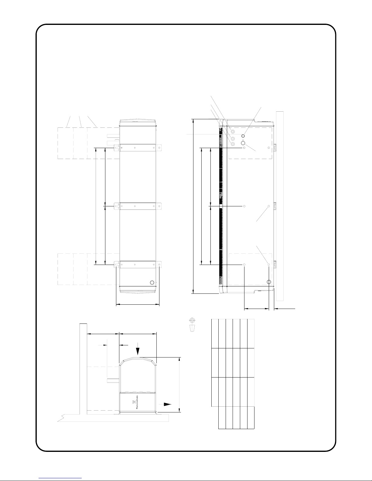
295
E E
D
C C
B
A
168
36
255
377
PHV2000DXPHV1500DX
22961746
18961400
1300
700
1824
948
650 912
A (mm)
B (mm)
C (mm)
D (mm)
E (mm)
Hot Gas
Refrigerant Connection
Liquid line
Refrigerant Connection
100
Electrical Supply and
Control Wiring Inlets
for pipes
250 min.
PHV1000DX
1196
800
800
N/A
N/A
Optional sheet metal covers
to hide pipework, cables, etc.
250, 500 or 1000 high
Holes for M10 drop rods
4 for 1m unit, 6 for 1.5m/2m units
Use all drop rod holes !
FIGURE 1 – DIMENSIONS OF PHV HEAT PUMP AIR CURTAIN
9901025-2 Page 6 of 21
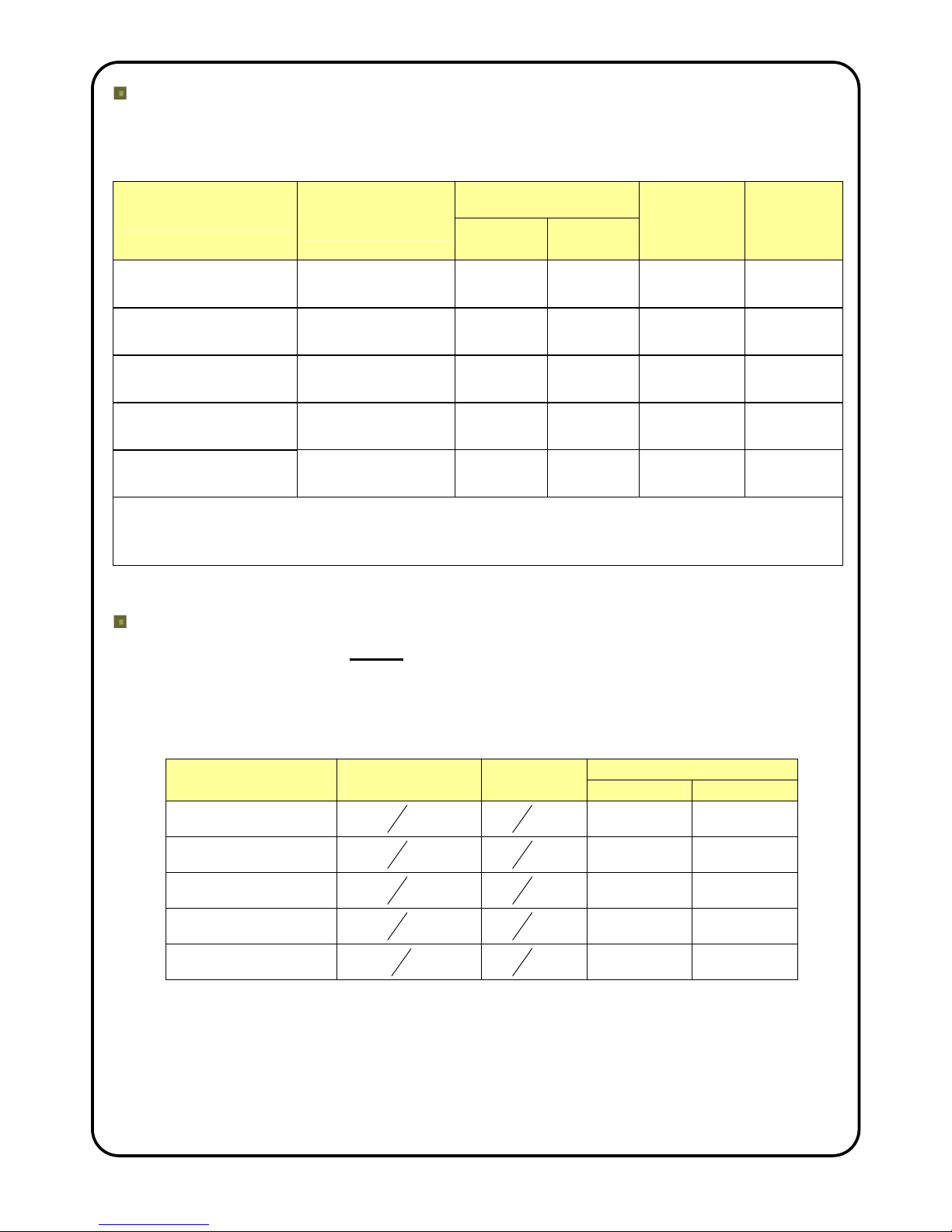
Mitsubishi Electric Outdoor Unit
The Mitsubishi Electric Outdoor Unit is selected to match its refrigerant heat output to
the size of the Air Curtain. See table below for size of outdoor unit to be used together
with performance data for the air curtain.
Heat Output (kW)
@outdoor air 7/6°C db/wb
Air Curtain
Mr Slim Outdoor
Unit
Full
Heat
Half
Heat
Max. Air
Volume
Flow Rate
(m3/h)
Max.
Noise
Level
dB(A) @3m
PHV1000 DXE HO PUHZ-RP71VHA 8.6 5.34 1400 56
PHV1500 DXE LO PUHZ-RP71VHA 10.1 5.6 2500 58
PHV1500 DXE HO
PUHZ-
RP140VKA/YKA
14.4 8.3 2600 58
PHV2000 DXE LO
PUHZ-
RP100VKA/YKA
14.1 7.9 3300 59
PHV2000 DXE HO PUHZ-RP200YKA 21.3 11.2 3130 59
Indoor Air Temperature = 20ºC
Performance figures derived from independent testing by UK test houses BRE and BSRIA in accordance with
test standard EN 14511.
The air curtain normally operates under automatic temperature control and can also run at part load.
Refrigerant Pipework
This must be carried out before connection of any electrical and controls cables
and in accordance with the Instructions that come with the Mitsubishi Electric
Outdoor Unit. This work must only be undertaken by a Mitsubishi Electric
approved Contractor.
Refrigerant installation pipework sizes are as follows :-
Maximum Pipe Run
Air Curtain
Discharge Line
(Gas)
Liquid
Line
Length Height
PHV1000 DXE HO
8
5
in.
8
3
in.
50m 30m
PHV1500 DXE LO
8
5
in.
8
3
in.
50m 30m
PHV1500 DXE HO
8
5
in.
8
3
in.
50m 30m
PHV2000 DXE LO
8
5
in.
8
3
in.
50m 30m
PHV2000 DXE HO
1
8
1
in.
8
3
in.
100m 30m
It is intended that refrigerant pipe connections to the air curtain are made using brazed
joints and these must be carried out in a professional and safe manner. If installation
pipe sizes for the discharge (gas) line and liquid line are different from the pipe
connection sizes on the air curtain, suitable pipe reducers must be used for the
connection. R410a refrigerant systems can operate at pressures up to 610 psi (c. 42
Bar). These brazed joints may well be located in a public area and a weakness leading
to an explosion could be extremely dangerous. The air curtain with its coil is

9901025-2 Page 7 of 21
manufactured in accordance with the Pressure Equipment Directive and the installation
must be carried out to a good standard of workmanship. Remove the protective plastic
film on top of the air curtain before starting work. Use a heat sink on the copper pipes
when brazing to reduce the transfer of heat to the inside of the air curtain where
sensitive components are located.
To gain access inside the Air Curtain
To gain access for connection of the electrical supply, controls
wiring and to work on the unit during commissioning, remove the
air inlet grilles and the bottom access panel.
First remove the plastic end caps if already fitted by pulling off to
the side (see picture).
Then remove each inlet grille in turn with its filter by unfastening
the M4 Pozi Head screw at the bottom corner of the grille. Use a
Pozi No.1 screwdriver to access the screw via the elongated
hole at each bottom corner of the grille (see adjacent picture).
To remove the bottom access panel unfasten the access panel
securing screws, one at each end and two in the centre
(PHV1500 and PHV2000 units) and slide the panel out forwards.
Please note: All the panels of the air curtain are covered in a
protective plastic film which should be removed.
Electrical Supply to the Air Curtain
This must be carried out AFTER the connection of the refrigerant pipework. All
electrical wiring and connections MUST be carried out by a competent qualified
electrician in accordance with the latest edition of the IEE wiring regulations
and/or local statutory regulations. (see also Wiring Diagram on Page 10)
• A local isolator having a contact separation of at least 3mm on all poles must be
fitted in the electrical supply to the air curtain and located in an accessible position
adjacent to the unit. 1 phase if defrost electric heaters are not required. 3 phase if
defrost electric heaters are required.
• The appliance must be connected using cables having an appropriate temperature
rating (heat resistant).
• Ensure that the supply cables, circuit breakers and other electrical installation
equipment are correctly sized for the air curtain being installed. See Table
overleaf.
• A 20mm size cable gland or conduit connector should be used for the Electrical
Supply into the air curtain.
• This appliance must be Earthed.
access panel
location
of screw
 Loading...