

Mitsubishi Electric PH440, PH440 NLX User Manual

124577UG September 1998
MOTHERBOARD DIVISION
User Guide
PH440 NLX Motherboard
www.mitsubishi-motherboard.com
PH440 NLX Motherboard User Guide September 1998
MITSUBISHI ELECTRIC MOTHERBOARD DIVISION PAGE 2 OF 51
Document History
Issue Description Date
1.0 Preliminary May 98
1.1 Update for production motherboards July 98
1.2 Style update, added installation and upgrade guides September 98
Trademarks mentioned within this document are the properties o f their r e spective
owners. Details available on request.
Information contained in this document is subject to change without notice and does not
represent a commitment on the part of Mitsubishi Electric Motherboard Division.
No part of this manual may be reproduced or transmitted in any form or by any means
electronic or mechanical including photocopying and recording, for any purpose, without
the express written permission of the publishers.
Published by:
Mitsubishi Electric
Motherboard Division
3500 Parkside
Birmingham Business Park
Birmingham, England
B37 7YS

PH440 NLX Motherboard User Guide September 1998
MITSUBISHI ELECTRIC MOTHERBOARD DIVISION PAGE 3 OF 51
SAFETY AND REGULATORY NOTICES
GENERAL
Battery
This product contains a lithium battery.
Do not use a metal or other conductive implement to remove the battery. If a short-circuit is
made between its positive and negative terminals the battery may explode.
Replace a discharged battery with one of the same type; another type may explode or ignite.
Follow the instructions contained in the User Guide to replace the battery. Dispose of a
discharged battery promptly and in accordance with the battery manufacturer’s recommended
instructions. Do not recharge, disassemble or incinerate the discharged battery. Keep away from
children.
Anti-static precautions
Warning
Static electricity ca n cause permanen t dama ge to elec tronic co mponen ts. You sh ould be
aware of this risk, and take precautions against the discharge of static electricity.
This product is at risk from static discharge because the electronic components of the
motherboard are exposed. Memory modules and replacement processors are examples of
electrostatic sensitive devices (ESSDs).
All work that involves contact with the PH440 NLX Motherboard should be done in an area
completely free of static electricity. We recommend using a Special Handling Area (SHA) as
defined by EN 100015-1: 1992. This means that working surfaces, floor coverings and chairs
must be connected to a common earth reference point, and you should wear an earthed wrist
strap and anti-static clothing. It is also a good idea to use an ionizer or humidifier to remove
static from the air.
Handle static-sensitive items with extreme care. Hold add-on components only by their edges,
avoiding their electrical contacts. In general, do not handle static-sensitive items unnecessarily.
Keep all conductive material, and food and drink, away from your work area and PH440 NLX
Motherboard.
LEGALITIES
This product complies with the relevant clauses of the following European Directives (and all
subsequent amendments):
Low Voltage Directive 73/23/EEC
EMC Directive 89/336/EEC
CE Marking Directive 93/68/EEC
Important
This product, when supplied, complies with the CE Marking Directive and its strict legal
requirements. U se o nly pa rt s test ed and a pp rov ed b y Mits ubishi E lec tric Mothe rboa rd
Division.

PH440 NLX Motherboard User Guide September 1998
MITSUBISHI ELECTRIC MOTHERBOARD DIVISION PAGE 4 OF 51
STANDARDS
Safety
This product complies with the American Safety Standard UL1950.
Electro-magnetic Compatibility (EMC)
This product complies with the following European EMC standards:
Emissions EN50022 Class B
Immunity EN50082-1 Class B
This product also complies with the following American EMC standard:
FCC Class B
FCC Compliance Statement
Note: This equipment has been tested and found to comply with the limits for a Class B digital
device, pursuant to part 15 of the FCC Rules. These limits are designed to provide reasonable
protection against harmful interference in a residential installation. T his equipment generates,
uses and can radiate radio frequency energy and, if not installed and used in accordance with the
instructions, may cause harmful interference to radio communications. However, there is no
guarantee that interference will not occur in a particular installation. If this equipment does cause
harmful interference, which can be determined by turning the equipment off and on, the user is
encouraged to try to correct the interference by one or more of the following measures:
♦
Reorient or relocate the receiving antenna.
♦
Increase the separation between the equipment and receiver.
♦
Connect the equipment into an outlet on a circuit different to that which the receiver is
connected.
♦
Consult the dealer or an experienced radio/TV technician for help.
Important
You are cautioned that any change or modification to the product not expressly approved by
the manufactur er cou ld void the app rova ls held by this produc t.

PH440 NLX Motherboard User Guide September 1998
MITSUBISHI ELECTRIC MOTHERBOARD DIVISION PAGE 5 OF 51
CONTENTS
1 Overview 8
Motherboard Features......................................................................................................................9
Configuration Options...................................................................................................................10
Build-time ................................................................................................................................10
User Configurable.................................................................................................................... 10
Block Diagram............................................................................................................................... 11
2 Installation guide 12
3 Upgrading the motherboard 14
Adding more memory....................................................................................................................14
Fitting and removing DIMMs..................................................................................................14
Fitting a DIMM........................................................................................................................ 15
Removing a DIMM.................................................................................................................. 15
Adding more video memory..........................................................................................................15
The processor assembly.................................................................................................................16
To fit a new processor.............................................................................................................. 17
Replacing the battery for the configuration CMOS....................................................................... 18
4 Electronics 19
Processor........................................................................................................................................ 19
Core Logic..................................................................................................................................... 19
Concurrency............................................................................................................................. 20
Level 2 Cache................................................................................................................................20
Memory ......................................................................................................................................... 20
Motherboard............................................................................................................................. 20
DIMM ......................................................................................................................................20
BIOS ........................................................................................................................................ 20
Configuration RAM.................................................................................................................20
Video ............................................................................................................................................. 21
VGA Controller........................................................................................................................21
AGP..........................................................................................................................................22
Audio.............................................................................................................................................23
ESS Solo 1 ............................................................................................................................... 23
Real Time Clock............................................................................................................................23
Standard I/O................................................................................................................................... 24

PH440 NLX Motherboard User Guide September 1998
MITSUBISHI ELECTRIC MOTHERBOARD DIVISION PAGE 6 OF 51
Keyboard and Mouse...............................................................................................................24
Floppy Disk Interface...............................................................................................................24
Serial Ports...............................................................................................................................24
Parallel Port.............................................................................................................................. 24
Additional I/O................................................................................................................................24
IDE Disk Controller................................................................................................................. 24
Universal Serial Bus (USB) .....................................................................................................24
Security..........................................................................................................................................24
Motherboard Power.......................................................................................................................25
Processor Power....................................................................................................................... 25
Battery......................................................................................................................................25
Power Management.......................................................................................................................25
Standby Switch.........................................................................................................................25
Behaviour After AC-Disconnect.............................................................................................. 25
Sleep State Indication............................................................................................................... 25
System Management...................................................................................................................... 26
Heceta II System Monitor........................................................................................................26
Fan Control.................................................................................................................................... 26
Expansion Slots ............................................................................................................................. 26
Industry Standard Architecture (ISA)......................................................................................26
Peripheral Component Interconnect (PCI)...............................................................................26
Bus Resource Utilisation ............................................................................................................... 27
ISA DMA Channels................................................................................................................. 27
ISA Interrupts........................................................................................................................... 27
PCI Interrupts...........................................................................................................................27
PCI Device Selection (motherboard devices)...........................................................................28
PCI Arbitration......................................................................................................................... 28
5 BIOS Setup & POST 29
BIOS Setup.................................................................................................................................... 29
Control keys............................................................................................................................. 29
Getting help in BIOS Setup......................................................................................................30
Reserving ISA legacy resources...............................................................................................30
Multi-boot facility.......................................................................................................................... 30
Power-on self-test.......................................................................................................................... 31
Recoverable POST errors.........................................................................................................31
Terminal POST errors and beep codes..................................................................................... 32

PH440 NLX Motherboard User Guide September 1998
MITSUBISHI ELECTRIC MOTHERBOARD DIVISION PAGE 7 OF 51
6 Electrical 39
Power Requirements......................................................................................................................39
PCB................................................................................................................................................39
7 Connector Assignments 40

PH440 NLX Motherboard User Guide September 1998
MITSUBISHI ELECTRIC MOTHERBOARD DIVISION PAGE 8 OF 51
1 OVERVIEW
PH440 NLX is a Pentium II® processor-based NLX profile motherboard.
The design of PH440 NLX is based around the following components.
♦
Intel Pentium II
®
processor in Slot 1.
♦
Intel 440BX host bridge and system controller.
♦
Intel PIIX4e ISA bridge and peripheral and power management controller.
♦
SMSC 37C677 I/O Combo.
♦
ATI AGP 3D Rage Pro AGP or 3D Rage IIC AGP video controller with SGRAM frame
buffer.
♦
ESS Solo 1 audio controller.
Pentium II
®
Processor
The Pentium
®
II processor adds MMX technology to the P6 micro-architecture in a cartridge
package which also includes a second-level cache. The cartridge plugs into a 242-pin slot
connector (slot 1) on the motherboard and operates at speeds from 233MHz.
440BX North bridge
The 440BX North bridge connects the processor to the SDRAM main memory, an AGP port and
PCI bus interface. The device is housed in a 492-pin BGA package.
PIIX4e ISA bridge
The PIIX4e provides the PCI to ISA bus bridge and contains the system’s RTC, the IDE
interfaces, the DMA and Interrupt Controllers. The PIIX4e also provides ACPI support, an
SMbus controller and all the general purpose I/O ports used on the PH440 NLX motherboard.
The PIIX4e device is packaged in a 324 pin BGA.
PH440 NLX Motherboard User Guide September 1998
MITSUBISHI ELECTRIC MOTHERBOARD DIVISION PAGE 9 OF 51
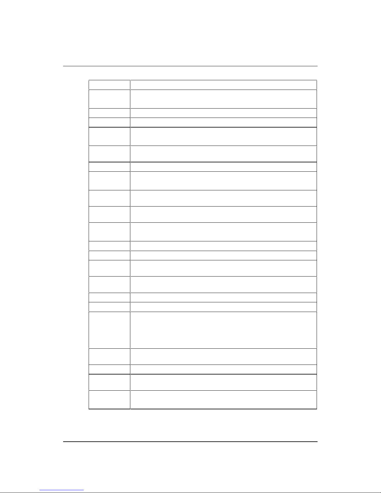
MOTHERBOARD FEATURES
Form factor NLX, 9.0" wide x 11.2" long
Processor Slot 1 with the VRM8.2 regulator on motherboard.
Accepts all Pentium II
®
(100MHz bus) processors
Core logic Intel 440BX & PIIX4e
Cache L2 cache included on processor module.
Memory –
RAM
3 DIMM sockets to accept 168 pin un-buffered PC100 SDRAM modules.
64-bit or 72-bit ECC with 1-bit correct, 2-bit detect.
Memory Flash ROM
2Mb flash ROM. Includes BIOS, Setup-in-ROM, VGA, USB, DMI,
120MB floppy etc.
Buses Supports 4 bus-master PCI slots and 5 ISA slots via riser.
VGA AGP video via ATI Rage IIc or ATI Rage Pro.
2 or 4MB SGRAM with upgrades via SODIMM module
Audio –
controller
Active speaker support only (external). Internal mono speaker and PCB
mounted ‘beeper’. ESS Solo 1 CODEC.
Hard Disk &
CD-ROM
Dual UltraDMA33 interfaces for hard disk and CD-ROM.
Floppy Disk 720kB, 1.2MB (3-mode), 1.44MB 3½ drives, 1.2MB 5¼ drives.
Support for 120MB drives via ATA port.
Parallel Port IEEE 1284 (ECP & standard) on 25-way D-type
Serial Ports Dual 16550s. Two 9-way D-types on rear edge of motherboard.
USB
Two ports. Two configurations available as build option. Either two ports
on rear panel or one on rear and second through NLX riser.
Keyboard &
Mouse
PS/2-style connectors. USB with legacy support
Security Chassis intrusion detection via riser.
IR I/O Optional through NLX riser (input only).
Power
Management
Green and deep green via system management mode.
ACPI compatible.
Requires logic-controlled PSU.
Standby option with wake-up on interrupt, serial port activity or button.
System
Management
Hardware monitoring (Voltage, temperature and fan monitor) via Heceta II
device.
Plug & Play PC97 and PC98 compliant
Battery back-upOn-board lithium coin cell with 5 years typical life.
PCB 4-layer N LX form-factor.
All components on top side

PH440 NLX Motherboard User Guide September 1998
MITSUBISHI ELECTRIC MOTHERBOARD DIVISION PAGE 10 OF 51
CONFIGURATION OPTIONS
Build-time
The following items can be configurable at build-time and cannot be modified by the user.
♦
Video controller (Rage IIc or Rage Pro).
♦
Video memory and upgrade socket.
♦
AMC connector.
♦
MIDI & joystick header.
♦
Heceta II system monitor.
♦
+5V supply to VGA connector pin 9.
♦
Dual rear USB or single rear and riser.
Contact Mitsubishi Electric Motherboard Division to determine available configurations.
User Configurable
The user can configure the following items.
♦
Processor (Intel boxed products)
♦
Main memory DIMMs
♦
Video memory upgrade (where available)
♦
Processor speed (core/bus ratio)
♦
BIOS ROM write enable
♦
Function enable/disable jumpers (audio CODEC, VGA)
PH440 NLX Motherboard User Guide September 1998
MITSUBISHI ELECTRIC MOTHERBOARD DIVISION PAGE 11 OF 51
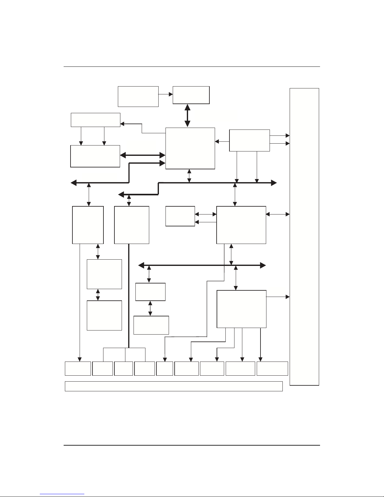
BLOCK DIAGRAM
PCI BUS
MEMORY
BUS
AGP BUS
IDE
FD
C
XBUS
BUFFER
BIOS ROM
TSSOP40
82443BX
NORTHBRIDGE
492 BGA
PIIX4e
324 BGA
MEMORY
DIMMS X 3
HOST BUS
NLX
RISER
ISA BUS
ESS
SOLO1
AUDIO
ATI
RAGE
VGA
CLOCK BUFFER
SMSC 37C67X
SUPER I/O
100 PQFP
KEYBOARD
& MOUSE
PARALLEL
PORT
SERIAL
COM1
SERIAL
COM2
MIC
IN
LINE
IN
LINE
OUT
VGA
OUTPUT
REAR PANEL CONNECTORS
VGA
MEMORY
SGRAMX2
VGA
MEMORY
UPGRADE
SODIMM 144
CORE VOLTAGE
DC-DC
CONVERTOR
MOTHERBOARD
CLOCK
GENERATOR
USB
HECETA 2
SLOT1
CPU

PH440 NLX Motherboard User Guide September 1998
MITSUBISHI ELECTRIC MOTHERBOARD DIVISION PAGE 12 OF 51
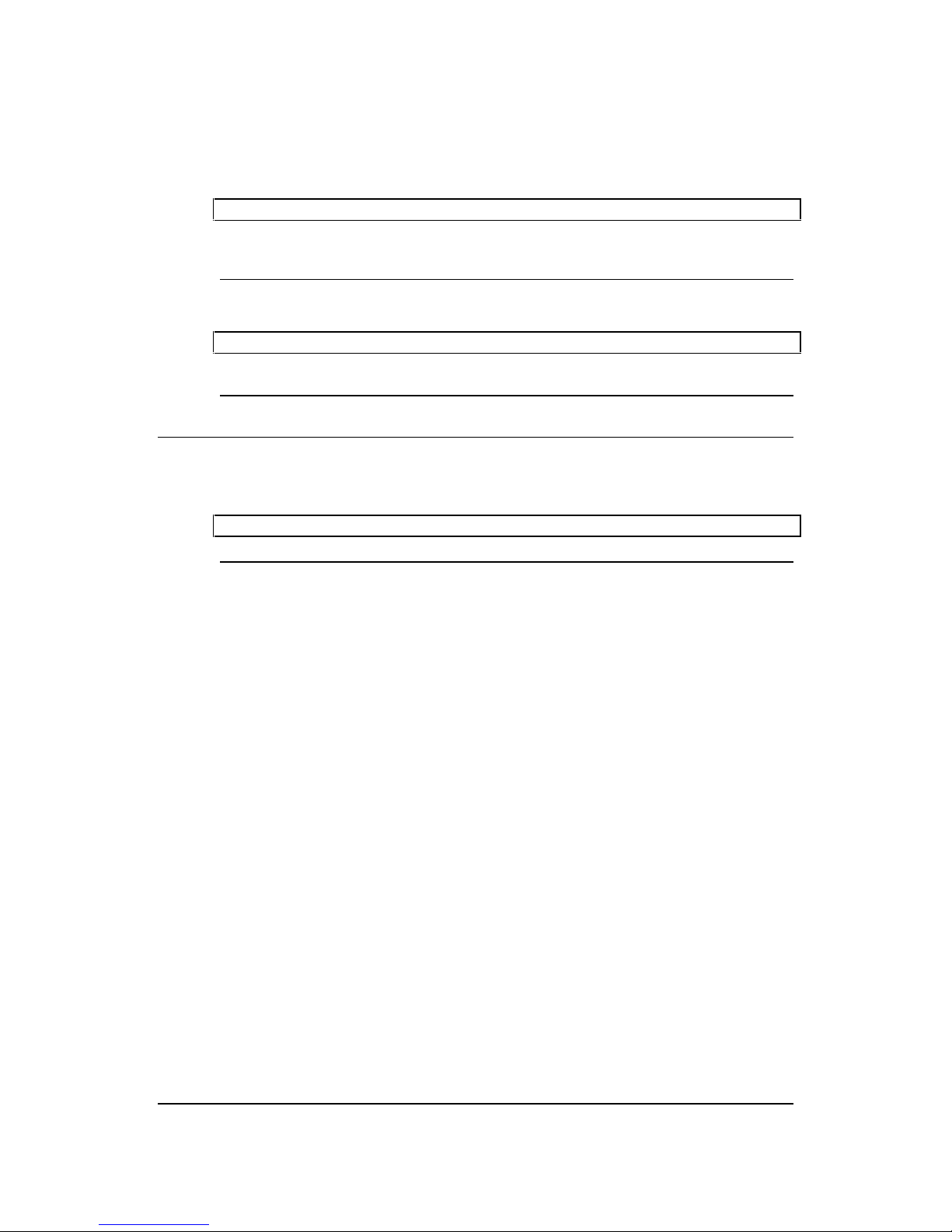
2 INSTALLATION GUIDE
Warning
Static electricit y can cau se perman ent damage to electron ic compon ent s. You shou ld be
aware of this risk, and take precautions against the discharge of static electricity.
1 3V Lithium cell
2 Processor socket
3 Processor fan power
4Memory DIMMs
5 Multimedia upgrade
connector
6Video memory
upgrade socket
7 ATAPI CD Audio
8 MIDI/joystick header
9 NLX riser connector
J1-4 Processor speed
selection
J5 Video enable jumper
J6 Motherboard audio
enable
J7 BIOS write protect
J8 Configuration
memory clear
J9 Motherboard
speaker enable
A Line input
B Microphone input
C Line output
DUSB
E Serial port 2
F Keyboard
G Mouse
H Serial port 1
I VGA monitor
J Parallel port
H I
J
F
G
D
C
B
A
E
3
2J9
1
5
J1
8
9
4
6
J2
J3
J4
J5
J6
J8
J7
7

PH440 NLX Motherboard User Guide September 1998
MITSUBISHI ELECTRIC MOTHERBOARD DIVISION PAGE 13 OF 51
Processor Core/Bus Ratio – J1-J4
J1 J2 J3 J4 Ratio Speed at
100MHz
X X 3.5 350
X X X 4.0 400
X X 4.5 450
X – Jumper fitted
VGA Enable – J5
1-2 Disable on-board VGA controller
2-3 Enable on-board VGA controller
PCI Audio CODEC Enable – J6
1-2 Enable audio CODEC
2-3 Disable audio CODEC
BIOS Program Enable – J7
1-2 Disable BIOS updates
2-3 Enable BIOS updates
Clear Configuration (CMOS) Memory – J8
(Ensure AC is disconnected from the power supply before moving this jumper)
1-2 Normal operation
2-3 Clear CMOS (jumper must be returned to normal position before power-on)
Enable Motherboard Speaker – J9
1-2 Enabled
2-3 Disabled
PH440 NLX Motherboard User Guide September 1998
MITSUBISHI ELECTRIC MOTHERBOARD DIVISION PAGE 14 OF 51
3 UPGRADING THE MOTHERBOARD
Caution
Care must be taken in the purchase of upgrade parts to ensure both compatibility with the
system and the compliance with appropriate approvals and certification, e.g. CE marking
within Europe. Using non-approved parts may invalidate your warranty and system approvals.
Upgrading the motherboard is not difficult, but if you do not feel confident about the work
involved, you may wish to have your supplier or service organisation complete it for you.
Warning
Never carry out any work inside the computer with AC power applied. Turn off the computer
and unplug all power cords before starting work.
ADDING MORE MEMORY
The motherboard has three DIMM (Dual Inline Memory Module) sockets, each of which accepts
DIMMs of up to 128 Mbytes, in any combination. The slot furthest from the processor (MM1)
should be used first.
DIMM specification
The memory modules should meet the PC100 specification.
Fitting and removing DIMMs
Read all of these instructions through carefully before you start work.
Turn off the computer and unplug all power cords. Take suitable anti-static precautions and
remove the system cover. Leave the DIMM in the antistatic packaging until the last possible
moment and when you do take the DIMM out of its packaging, hold it by its ends and avoid
touching the metal contacts.
Follow the diagrams and simple instructions on the following pages to insert each DIMM.
Afterwards
After you have fitted new modules, check that the system recognises all the memory. If not,
check that you have:
♦
Correctly fitted the DIMMs in their slots.
♦
Installed DIMMs of the correct type.
It may be necessary to refit the original memory to check if there is a problem with your new
modules.
PH440 NLX Motherboard User Guide September 1998
MITSUBISHI ELECTRIC MOTHERBOARD DIVISION PAGE 15 OF 51
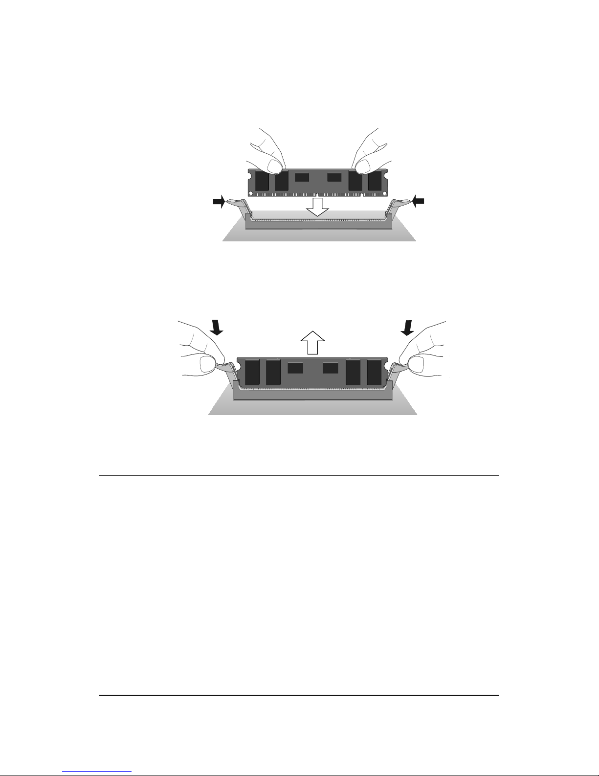
Fitting a DIMM
Do not use excessive force. If the module will not fit easily, remove it and start again.
The DIMM is inserted vertically and held in place by the clips at each end.
Removing a DIMM
Do not use excessive force. If the module will not come free easily, check that the holding clips
are clear of the module ends.
Press the tabs on both of the socket’s end clips at the same time. This releases the DIMM and
lifts it partly out of the socket.
ADDING MORE VIDEO MEMORY
Video memory is memory reserved for use by the on-board video controller. More video
memory can provide more colours or higher resolutions to an extent determined by the
capabilities of your monitor.
Check the amount of video memory fitted in your computer. You must fit a module of equal
value. For exa mple, if your computer has 2MB of video memory, you must fit a 2MB SODIM M
(Small Outline Dual Inline Memory Module).
1. Turn off the computer and unplug all power cords.
2. Take suitable anti-static precautions and remove the system unit cover.
3. Remove any expansion cards that impede access to the video memory upgrade socket (see
the motherboard diagram at the start of this chapter).
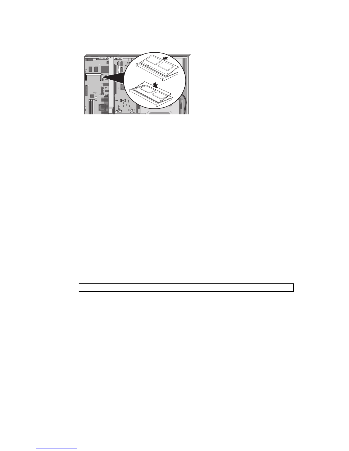
4. Unpack the upgrade kit. Hold the SODIMM chip by its edges and be careful not to touch
the metal pins.
PH440 NLX Motherboard User Guide September 1998
MITSUBISHI ELECTRIC MOTHERBOARD DIVISION PAGE 16 OF 51
5. Insert the SODIMM into the socket as shown in the illustration.
6. Replace any expansion cards you removed earlier and refit the system unit cover.
You can now reconfigure your operating system to use the expanded capabilities of the video
controller.
THE PROCESSOR ASSEMBLY
To remove the existing processor
1. Turn off the computer and unplug all power cords. Take suitable anti-static precautions and
remove the system cover.
2. If the system was in use just before starting this procedure, the processor may be hot, wait
until it cools.
3. If there are any expansion cards fitted that obstruct access to the processor, you may have to
remove them.
4. See ‘A’ in the illustration. Carefully squeeze together the grips at both ends (1) of the
heatsink support bracket (2) and slide it away.
◊
Some designs of heatsink do not have this bracket fitted.
5. See ‘B’ in the illustration. Press in the clips (1) at both ends of the top of the processor body
to depress the retaining pins out of the vertical supports. Then lift the processor body (2) out
of the socket.
Caution
Handle the processor with care, by the body only. Avoid touching the connector at the
bottom. Store in an antistatic container.
 Loading...