

Mitsubishi PFFY-WP20VLRMM-E, PFFY-WP50VLRMM-E, PFFY-WP25VLRMM-E, PFFY-WP32VLRMM-E, PFFY-WP40VLRMM-E Technical & Service Manual
Air-Conditioners
TECHNICAL & SERVICE MANUAL
Models
PFFY-WP20VLRMM-E
PFFY-WP25VLRMM-E
PFFY-WP32VLRMM-E
PFFY-WP40VLRMM-E
PFFY-WP50VLRMM-E
2013
ii
HWE12100 GB
Safety Precautions
Read before installation and performing electrical work
Symbol explanations
Thoroughly read the following safety precautions prior to installation.
Observe these safety precautions for your safety.
This equipment may have adverse effects on the equipment on the same power supply system.
Contact the local power authority before connecting to the system.
WARNING
This symbol indicates that failure to follow the instructions exactly as stated poses the risk of serious injury or death.
CAUTION
This symbol indicates that failure to follow the instructions exactly as stated poses the risk of serious injury or dam-
age to the unit.
Indicates an action that must be avoided.
Indicates important instructions.
Indicates a parts that requires grounding.
Indicates that caution must be taken with rotating parts. (This symbol is on the main unit label.) <Color: Yellow>
Indicates that the parts that are marked with this symbol pose a risk of electric shock. (This symbol is on the main
unit label.) <Color: Yellow>
WARNING
Carefully read the labels affixed to the main unit.
WARNING
Do not use refrigerant other than the type indicated in the
manuals provided with the unit and on the nameplate.
Doing so may cause the unit or pipes to burst, or result in
explosion or fire during use, during repair, or at the time of
disposal of the unit.
It may also be in violation of applicable laws.
MITSUBISHI ELECTRIC CORPORATION cannot be held
responsible for malfunctions or accidents resulting from the
use of the wrong type of refrigerant.
Ask your dealer or a qualified technician to install the unit.
Improper installation by the user may result in water leakage, electric shock, or fire.
Properly install the unit on a surface that can withstand its
weight.
Unit installed on an unstable surface may fall and cause injury.
Only use specified cables. Securely connect each cable so
that the terminals do not carry the weight of the cable.
Improperly connected cables may produce heat and start a
fire.
Take appropriate safety measures against wind gusts and
earthquakes to prevent the unit from toppling over.
Improper installation may cause the unit to topple over and
cause injury or damage to the unit.
Do not make any modifications or alterations to the unit.
Consult your dealer for repair.
Improper repair may result in water leakage, electric shock,
or fire.
Only use accessories (i.e., air cleaners, humidifiers, electric
heaters) recommended by Mitsubishi Electric.
Do not make any modifications or alterations to the unit.
Consult your dealer for repair.
Improper repair may result in water leakage, electric shock,
or fire.
Do not touch the heat exchanger fins with bare hands.
The fins are sharp and pose a risk of cuts.
ii
HWE12100 GB
Precautions for handling units for use with water
WARNING
Properly install the unit according to the instructions in the
Installation Manual.
Improper installation may result in water leakage, electric
shock, or fire.
Have all electrical work performed by an authorized electrician according to the local regulations and the instructions
in this manual. Use a dedicated circuit.
Insufficient power supply capacity or improper installation
of the unit may result in malfunctions of the unit, electric
shock, or fire.
Keep electrical parts away from water.
Wet electrical parts pose a risk of electric shock, smoke, or
fire.
Securely attach the control box cover.
If the cover is not installed properly, dust or water may infiltrate and pose a risk of electric shock, smoke, or fire.
Only use the type of refrigerant that is indicated on the unit
when installing or relocating the unit.
Infiltration of any other types of refrigerant or air into the unit
may adversely affect the refrigerant cycle and may cause
the pipes to burst or explode.
Consult your dealer or a qualified technician when moving
or reinstalling the unit.
Improper installation may result in water leakage, electric
shock, or fire.
After completing the service work, check for a refrigerant
leak.
If leaked refrigerant is exposed to a heat source, such as a
fan heater, stove, or electric grill, toxic gases will be generated.
Do not try to defeat the safety features of the unit.
Forced operation of the pressure switch or the temperature
switch by defeating the safety features for these devices, or
the use of accessories other than the ones that are recommended by Mitsubishi Electric may result in smoke, fire, or
explosion.
Consult your dealer for proper disposal method.
CAUTION
Do not use the existing water piping.
Store the piping materials indoors, and keep both ends of
the pipes sealed until immediately before installation. Keep
the joints wrapped in plastic bags. If dust or dirt enters the
water circuit, it may damage the heat exchanger and cause
water leakage.
Only use water.
Only use clean water as a refrigerant. The use of water outside the specification may damage the refrigerant circuit.

CONTENTS
HWE12100 GB
I
Features
[1] Features.................................................................................................................................... 1
II
Components and Functions
[1] Components and Functions...................................................................................................... 2
III
Specfications
[1] Specifications............................................................................................................................ 3
1.Specfications .......................................................................................................................... 3
2.Electrical component specifications........................................................................................ 5
IV
Outlines and Dimensions
[1] Outlines and Dimensions.......................................................................................................... 6
V
Wiring Diagram
[1] Wiring Diagram ......................................................................................................................... 7
VI
Refrigerant System Diagram
[1] Refrigerant system diagram...................................................................................................... 8
VII
Troubleshooting
[1] Troubleshooting ........................................................................................................................ 9
1.Check methods....................................................................................................................... 9
2.DC fan motor (fan motor/indoor control board)..................................................................... 10
3.Address switch setting .......................................................................................................... 11
4.Voltage test points on the control board ............................................................................... 12
5.Dipswitch setting (Factory setting)........................................................................................ 13
6.Instructions for debris removal operation.............................................................................. 15
7.Instructions for the air vent operation ................................................................................... 15
VIII
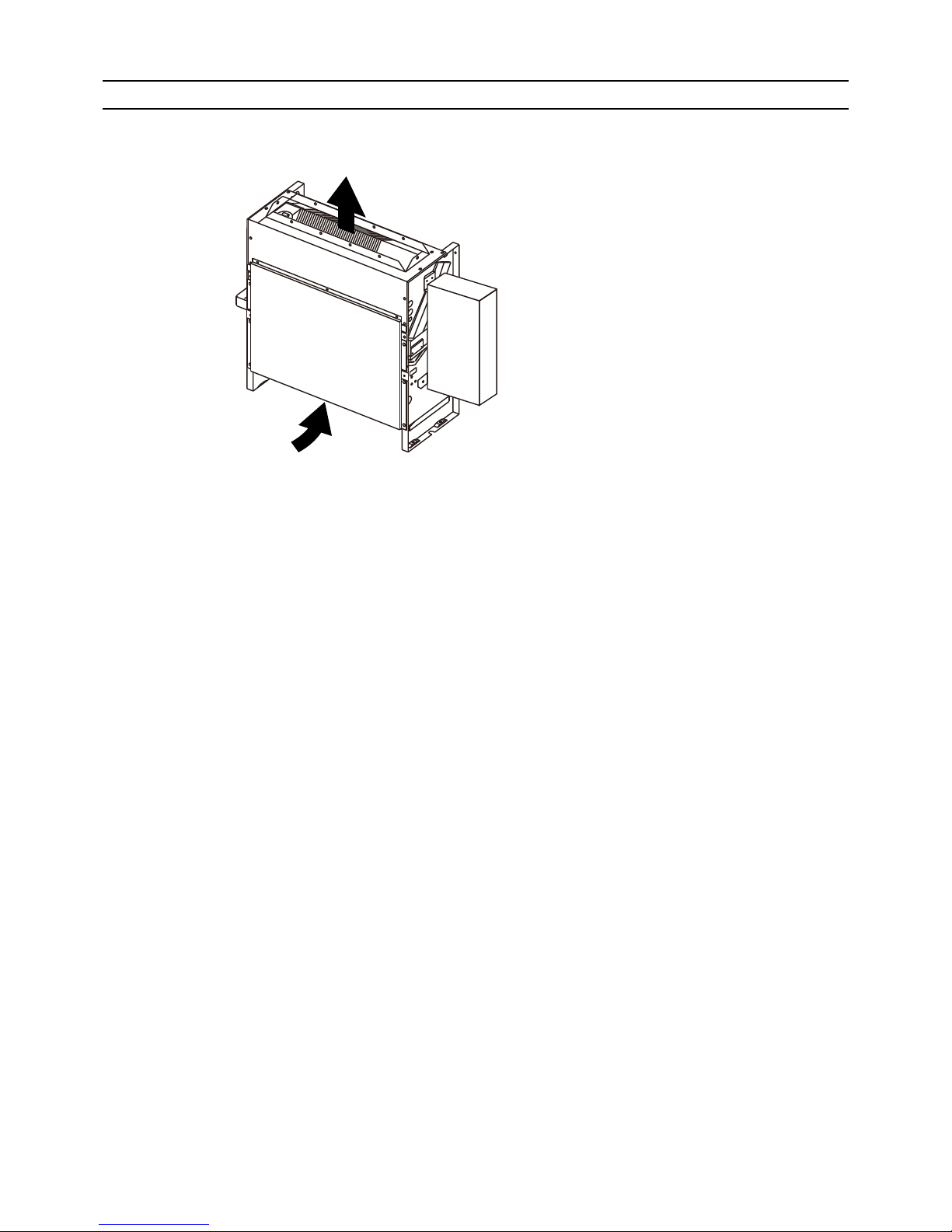
Disassembly Procedure
[1] Disassembly Procedure.......................................................................................................... 16
1.Control box ........................................................................................................................... 16
2.Thermistor (Intake air) .......................................................................................................... 17
3.Drainpan ............................................................................................................................... 18
4.Thermistor (Water inlet) (Water outlet) ................................................................................. 20
5.Fan and fan motor ................................................................................................................ 21
6.Heat exchanger .................................................................................................................... 22

HWE12100 GB
[ I Features ]
- 1 -
HWE12100 GB
I Features
[1] Features
Model Cooling capacity/Heating capacity
kW
PFFY-WP20VLRMM-E 2.2/2.5
PFFY-WP25VLRMM-E 2.8/3.2
PFFY-WP32VLRMM-E 3.6/4.0
PFFY-WP40VLRMM-E 4.5/5.0
PFFY-WP50VLRMM-E 5.6/6.3
[ II Components and Functions ]
- 2 -
HWE12100 GB
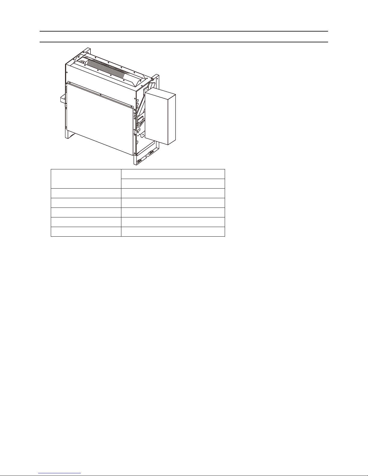
II Components and Functions
[1] Components and Functions
1. Indoor (Main) Unit
(A) Air
(A)
(A)
[ III Specfications ]
- 3 -
HWE12100 GB
III Specfications
[1] Specifications
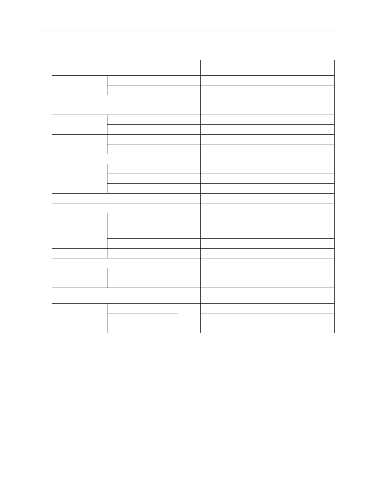
1. Specfications
*1 Cooling/Heating capacity indicates the maximum value at operation under the following condition,
<Cooling> Indoor temperature: 27°CDB/19°CWB (81°FDB/66°FWB Outdoor temperature: 35°CDB (95°FDB)
<Heating> Indoor temperature: 20°CDB (68°FDB) Outdoor temperature: 7°CDB/6°CWB (45°FDB/43°FWB)
*2 The external static pressure is set to 20Pa at factory shipment.
Model PFFY-
WP20VLRMM-E
PFFY-
WP25VLRMM-E
PFFY-
WP32VLRMM-E
Power supply Voltage V 220-240
Frequency Hz 50/60
Cooling capacity
*1
kW 2.2 2.8 3.6
Heating capacity
*1
kW 2.5 3.2 4.0
Power consumption
*2
Cooling kW 0.04 0.04 0.05
Heating kW 0.04 0.04 0.05
Current consumption
*2
Cooling A 0.35 0.35 0.47
Heating A 0.35 0.35 0.47
External finish (Munsel No.) Galvanized steel plate
Dimensions Height mm 639
Width mm 886 1006
Depth mm 220
Net weight
kg 22 25
Heat exchanger Cross fin (Aluminium fin and cupper tube)
Fan Type Sirocco fan x 1 Sirocco fan x 2
Airflow rate
(Low-Mid-High)
m
3
/min 4.5-5.0-6.0 6.0-7.0-8.0 7.5-9.0-10.5
External static pressure Pa 20-40-60
Motor Output kW 0.096
Air filter PP Honeycomb fabric
Diameter of
water pipe
Inlet in Rc3/4 screw
Outlet in Rc3/4 screw
Drain pipe dimensions mm
[in.]
Accesory hose ø27 [1-3/32] (top end : ø20 [13/16])
Operating noise
(Low-Mid-High)
20Pa dB (A) 31-33-38 31-33-38 31-35-38
40Pa 32-37-39 32-37-39 34-37-40
60Pa 36-38-42 36-38-42 36-40-42
[ III Specfications ]
- 4 -
HWE12100 GB
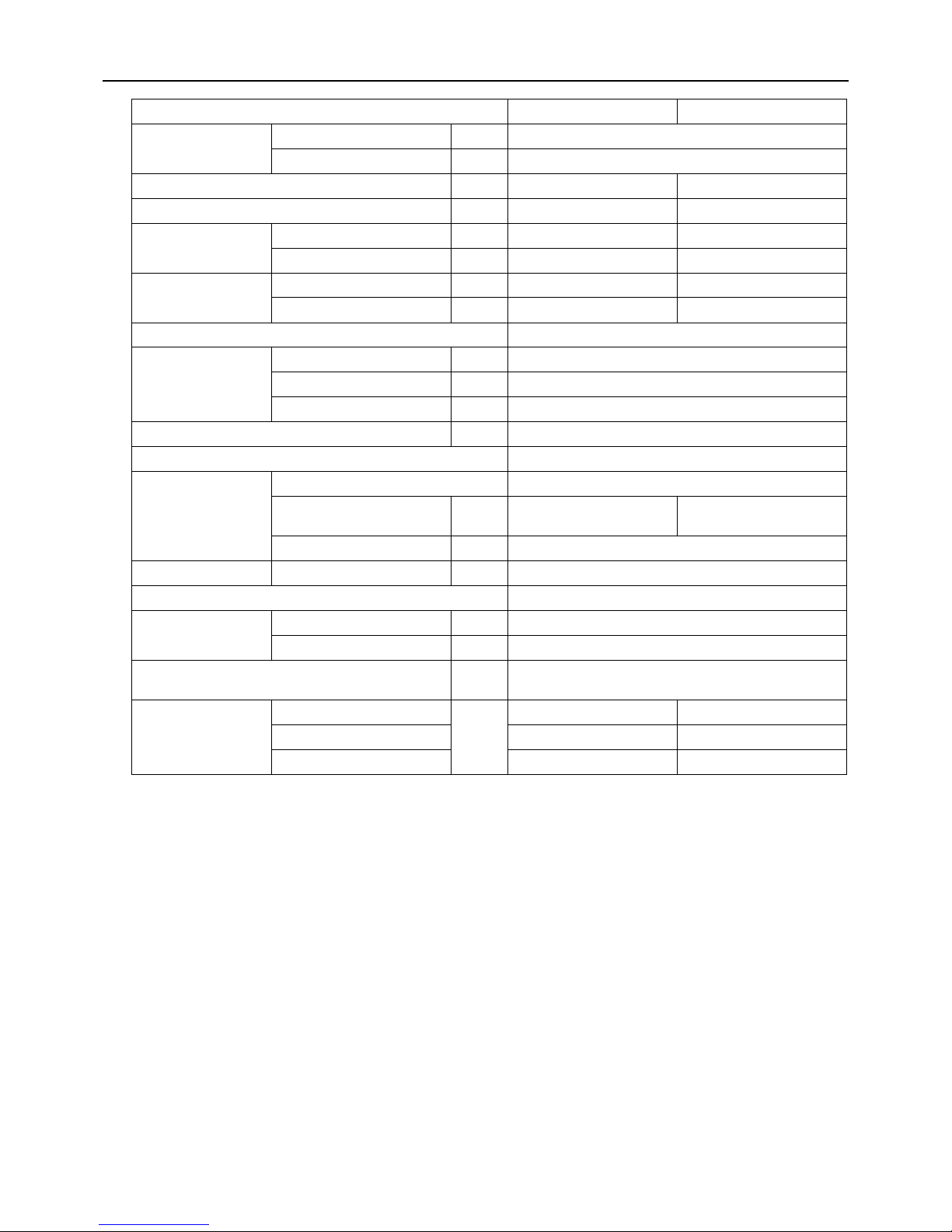
*1 Cooling/Heating capacity indicates the maximum value at operation under the following condition,
<Cooling> Indoor temperature: 27°CDB/19°CWB (81°FDB/66°FWB Outdoor temperature: 35°CDB (95°FDB)
<Heating> Indoor temperature: 20°CDB (68°FDB) Outdoor temperature: 7°CDB/6°CWB (45°FDB/43°FWB)
*2 The external static pressure is set to 20Pa at factory shipment.
Model PFFY-WP40VLRMM-E PFFY-WP50VLRMM-E
Power supply Voltage V 220-240
Frequency Hz 50/60
Cooling capacity
*1
kW 4.5 5.6
Heating capacity
*1
kW 5.0 6.3
Power consumption
*2
Cooling kW 0.05 0.07
Heating kW 0.05 0.07
Current consumption
*2
Cooling A 0.47 0.65
Heating A 0.47 0.65
External finish (Munsel No.) Galvanized steel plate
Dimensions Height mm 639
Width mm 1246
Depth mm 220
Net weight
kg 29
Heat exchanger Cross fin (Aluminium fin and cupper tube)
Fan Type Sirocco fan x 2
Airflow rate
(Low-Mid-High)
m
3
/min 8.0-10.0-11.5 10.5-13.0-15.0
External static pressure Pa 20-40-60
Motor Output kW 0.096
Air filter PP Honeycomb fabric
Diameter of
water pipe
Inlet in Rc3/4 screw
Outlet in Rc3/4 screw
Drain pipe dimensions mm
[in.]
Accesory hose ø27 [1-3/32] (top end : 20 [13/16])
Operating noise
(Low-Mid-High)
20Pa dB (A) 34-37-40 37-42-45
40Pa 37-39-43 38-44-47
60Pa 37-41-44 39-45-48
 Loading...