

Page 1
Air-Conditioners For Building Application
INDOOR UNIT
PFFY-P•VKM-E
INSTALLATION MANUAL
For safe and correct use, read this manual and the outdoor unit installation manual thoroughly before installing
the air-conditioner unit.
INSTALLATIONSHANDBUCH
Aus Sicherheitsgründen und zur richtigen Anwendung vor Installation der Klimaanlage die vorliegende Bedienungsanleitung und das Installationshandbuch gründlich durchlesen.
MANUEL D’INSTALLATION
Avant d’installer le climatiseur, lire attentivement ce manuel, ainsi que le manuel d’installation de l’appareil extérieur pour une utilisation sûre et correct.
INSTALLATIEHANDLEIDING
Lees deze handleiding en de installatiehandleiding van het buitenapparaat zorgvuldig door voordat u met het
installeren van de airconditioner begint.
MANUAL DE INSTALACIÓN
Para un uso seguro y correcto, lea detalladamente este manual de instalación antes de montar la unidad de
aire acondicionado.
MANUALE DI INSTALLAZIONE
Per un uso sicuro e corretto, prima di installare il condizionatore d’aria leggere attentamente il presente manuale
ed il manuale d’installazione dell’unità esterna.
ΕΓΧΕΙΡΙΔΙΟ ΟΔΗΓΙΩΝ ΕΓΚΑΤΑΣΤΑΣΗΣ
Για σωστή και ασφαλή χρήση, διαβάστε προσεκτικά αυτό το εγχειρίδιο, καθώς και το εγχειρίδιο εγκατάστασης
της εξωτερικής μονάδας, πριν από την εγκατάσταση της μονάδας κλιματιστικού.
MANUAL DE INSTALAÇÃO
Para uma utilização segura e correcta, leia atentamente este manual e o manual de instalação da unidade exterior antes de instalar o aparelho de ar condicionado.
MONTAJ ELKİTABI
Emniyetli ve doğru kullanım için, klima cihazını monte etmeden önce bu kılavuzu ve dış ünite montaj kılavuzunu
tamamıyla okuyun.
FOR INSTALLER
FÜR INSTALLATEURE
POUR L’INSTALLATEUR
VOOR DE INSTALLATEUR
PARA EL INSTALADOR
PER L’INSTALLATORE
ΓΙΑ ΑΥΤΟΝ ΠΟΥ ΚΑΝΕΙ ΤΗΝ ΕΓΚΑΤΑΣΤΑΣΗ
PARA O INSTALADOR
MONTÖR İÇİN
English (GB)
Deutsch (D)
Français (F)
Nederlands (NL)
Español (E)
Italiano (I)
Ελληνικά (GR)
Português (P)
Türkçe (TR)
РУКОВОДСТВО ПО УСТАНОВКЕ
Для обеспечения безопасной и надлежащей эксплуатации внимательно прочтите данное руководство и
руководство по установке наружного прибора перед установкой кондиционера.
安装说明书
在安装空调机之前,请先通读此安装说明书,以便安全正确地使用。
ДЛЯ УСТАНОВИТЕЛЯ
安装人员适用
Русский (RU)
中文 ( 中 )
Page 2
Contents
1. Safety precautions ........................................................................................ 2
2. Installation location ....................................................................................... 2
3. Installing the indoor unit................................................................................ 3
4. Refrigerant pipe ........................................................................................... 4
5. Drainage piping work .................................................................................... 5
1. Safety precautions
► Before installing the unit, make sure you read all the “Safety precau-
tions”.
► Please report to your supply authority or obtain their consent before
connecting this equipment to the power supply system.
Warning:
Describes precautions that must be observed to prevent danger of injury or
death to the user.
Caution:
Describes precautions that must be observed to prevent damage to the unit.
After installation work has been completed, explain the “Safety Precautions,” use,
and maintenance of the unit to the customer according to the information in the
Operation Manual and perform the test run to ensure normal operation. Both the
Installation Manual and Operation Manual must be given to the user for keeping.
These manuals must be passed on to subsequent users.
Warning:
• Ask the dealer or an authorized technician to install the air conditioner.
• Install the unit at a place that can withstand its weight.
• Use the specifi ed cables for wiring.
• Use only accessories authorized by Mitsubishi Electric and ask the dealer
or an authorized technician to install them.
• Do not touch the heat exchanger fi ns.
GB
• Install the air conditioner according to this Installation Manual.
Caution:
Do not use the existing refrigerant piping, when use R410A or R407C refrigerant.
•
•
Use ester oil, either oil or alkylbenzene (small amount) as the refrigerator oil
to coat fl ares and fl ange connections, when use R410A or R407C refrigerant.
• Do not use the air conditioner where food, pets, plants, precision instru-
ments, or artwork are kept.
• Do not use the air conditioner in special environments.
• Ground the unit.
6. Embedding the indoor unit in a wall.............................................................. 6
7. Electrical work .............................................................................................. 7
8. Test run ......................................................................................................... 8
9. Air outlet selection ........................................................................................ 9
: Indicates an action that must be avoided.
: Indicates that important instructions must be followed.
: Indicates a part which must be grounded.
: Indicates that caution should be taken with rotating parts.
: Indicates that the main switch must be turned off before servicing.
: Beware of electric shock.
: Beware of hot surface.
: At servicing, please shut down the power supply for both the Indoor and
ELV
Outdoor Unit.
Warning:
Carefully read the labels affi xed to the main unit.
• Have all electric work done by a licensed electrician according to local
regulations.
• If the air conditioner is installed in a small room, measures must be taken
to prevent the refrigerant concentration from exceeding the safety limit
even if the refrigerant should leak.
• The cut face punched parts may cause injury by cut, etc. The installers are
requested to wear protective equipment such as gloves, etc.
• Install an leak circuit breaker, as required.
• Use power line cables of suffi cient current carrying capacity and rating.
• Use only a circuit breaker and fuse of the specifi ed capacity.
• Do not touch the switches with wet fi ngers.
• Do not touch the refrigerant pipes during and immediately after operation.
• Do not operate the air conditioner with the panels and guards removed.
• Do not turn off the power immediately after stopping operation.
2. Installation location
200
B
700
D
Fig. 2-1
(mm)
A
600
C
The indoor unit should be supplied with the following accessories.
PART NUMBER
1
2
3
4
5
6
7
8
9
Drain hose 1
Pipe cover 1
Band 2
Indoor unit mounting bracket 1
Fixing screw for 4 4 × 25 mm 5
Wood screw for the indoor unit fi xation 4
Washer of
Felt tape (Used for left or left-rear piping) 1
MA Remote controller cable 1
ACCESSORY QUANTITY
6
4
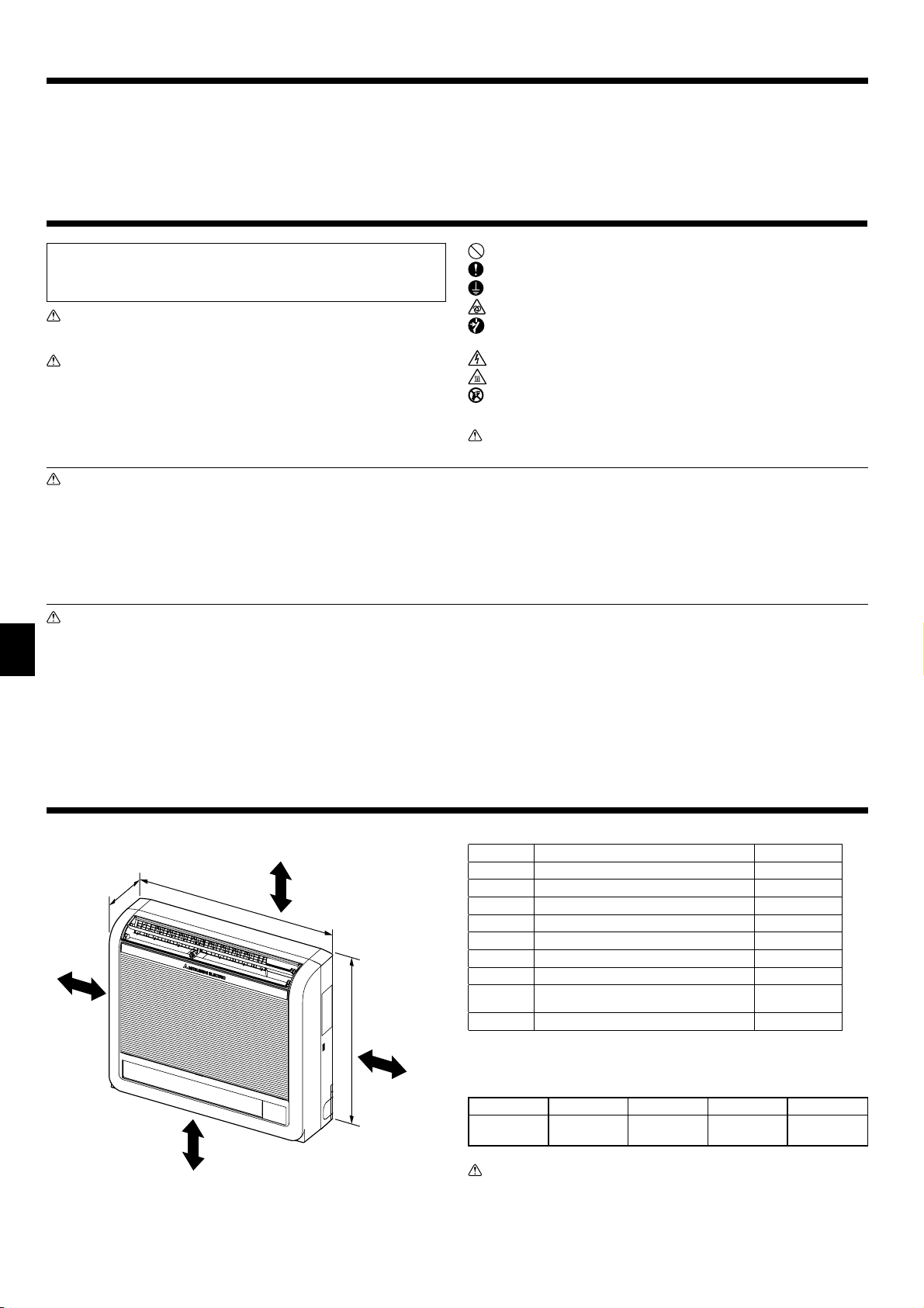
2.1. Outline dimensions (Indoor unit) (Fig. 2-1)
The unit must be securely installed on a structure that can sustain its weight.
Models A B C D
P20/25/32/40 100 mm or more 100 mm or more 100 mm or more
Warning:
Mount the indoor unit on a wall structure strong enough to withstand the
weight of the unit.
150 mm or below
from the fl oor
2
Page 3
3. Installing the indoor unit
200
131
(700)
Fig. 3-1
Fig. 3-3
131
14
586
(600)
674
Fig. 3-2
Fig. 3-4
(mm)
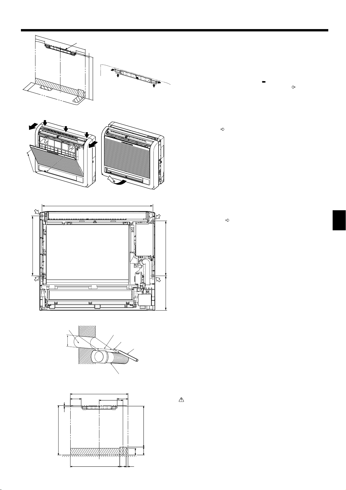
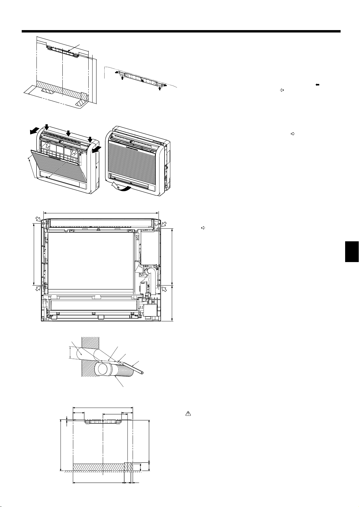
3.1. Indoor unit mounting bracket installation
• Install the bracket fi rmly to the wall structure (stud, etc.). (Fig. 3-1)
• Use a level to install the mounting bracket horizontally.
• Install the indoor unit 150 mm or below from the fl oor.
Indoor unit mounting bracket
A
Note:
To prevent the indoor unit mounting bracket from vibrating slightly, be sure
to fasten the bracket at the holes indicated by . In addition, fasten the
bracket at the holes indicated by if possible. (Fig. 3-2)
3.2. Indoor unit preparation
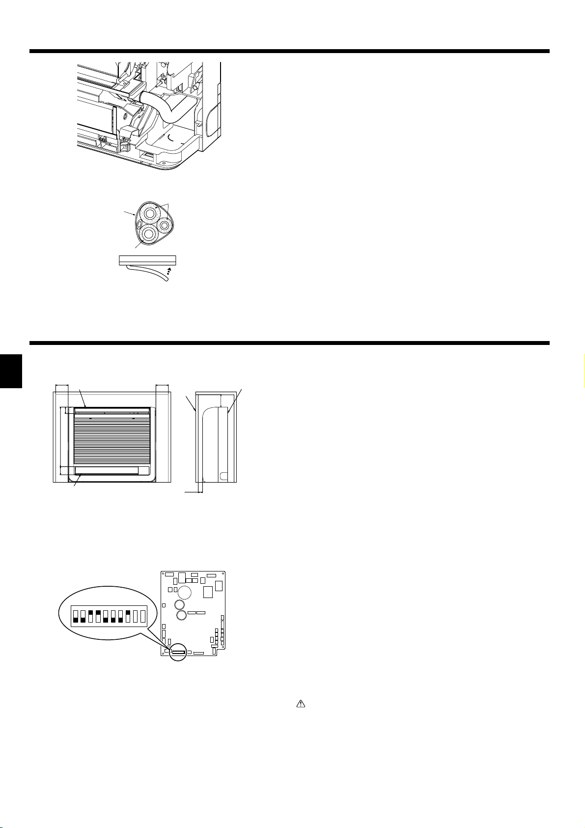
Press the 2 positions indicated by the arrows and open the front grille.
1
(Fig. 3-3)
Open the front grille and remove the 2 screws.
2
Open the horizontal vane for the upper air outlet, push the top of the front panel
3
in 3 locations, and then pull the top of the grille away from the indoor unit.
Screws
B
Lift up the front grille to remove it. (Fig. 3-4)
4
3.3. Indoor unit installation (Fig. 3-5)
• Hook the top of the indoor unit on the indoor unit mounting bracket.
• Use the included wood screws and washer, and fasten the indoor unit at 2 loca-
tions ( ) each at the top and the middle of the unit.
GB
Note:
Install the indoor unit securely to the wall, making sure that there is no gap
between the unit and the wall.
363
333210
Fig. 3-5
Fig. 3-6
1)
131
14
600
700
288
131
496
97
80
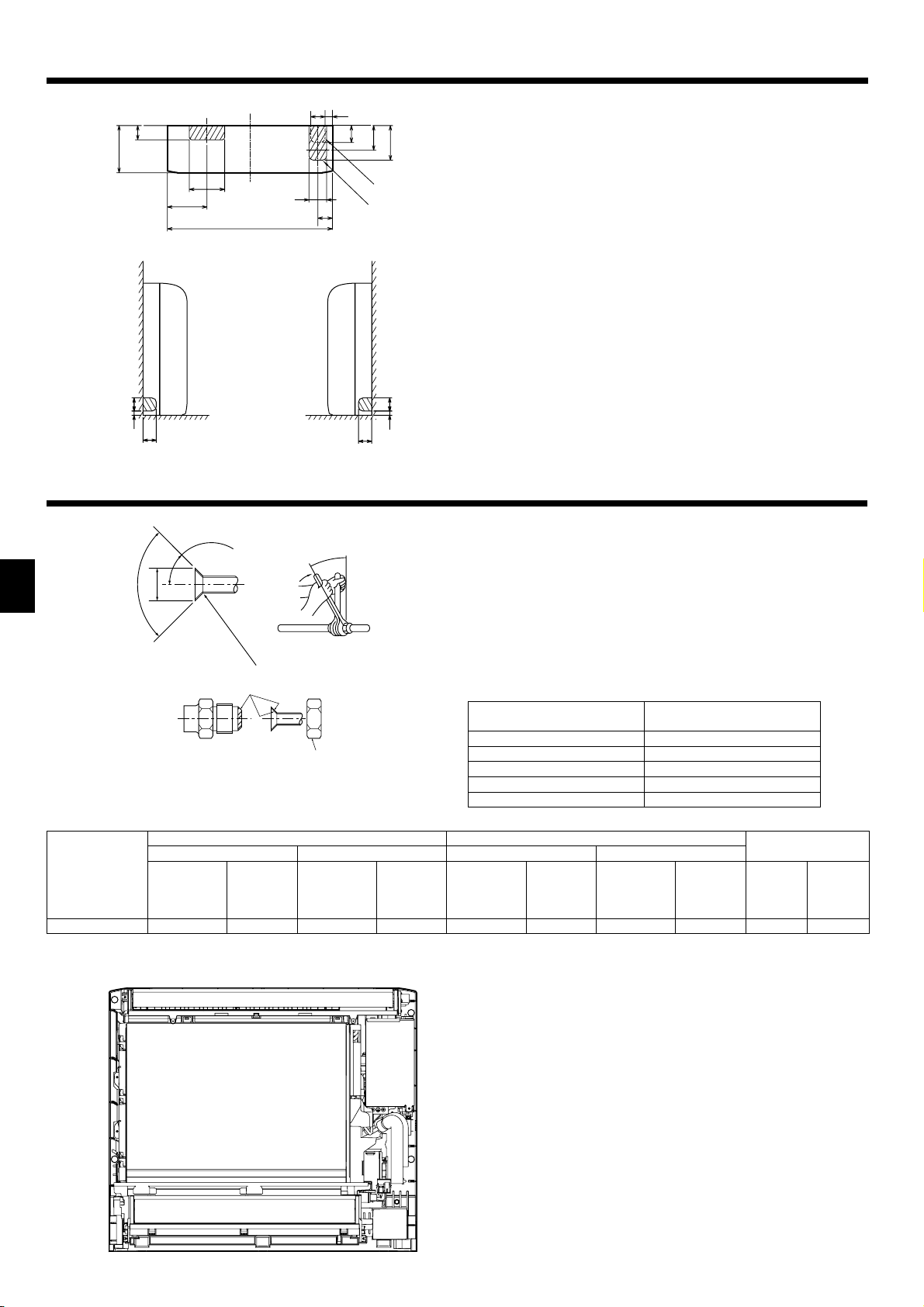
3.4. Making holes in the wall and fl oor
3.4.1. Making holes (Fig. 3-6)
Make ø65 mm or ø75 mm holes that are approximately 5–7 mm deep and an-
1
gled slightly downward outward from the room.
Insert the wall hole sleeves into the holes.
2
Wall hole
A
65 mm or 75 mm dia.
B
Indoor side
C
Wall hole cross section
D
Wall thickness
E
One scale
F
Cut with 1 extra scale length.
G
Wall hole sleeve
H
Caution:
Be sure to use the wall hole sleeves. Otherwise, the indoor/outdoor unit connecting wires may contact a metal object in the wall or, in the case of hollow
walls, small rodents may gnaw on the wires, resulting in a very dangerous
situation.
3.4.2. Determining hole positions
The areas where the piping can be routed are indicated with oblique lines in the
fi gure.
1) For rear or left-rear piping (Fig. 3-7)
(The following fi gure is a front view of the indoor unit installation location.)
599
Fig. 3-7
2378
3
Page 4
3. Installing the indoor unit
2)
60
200
150
168
700
61
75
62
(mm)
31
73
105
147
2) For right downward or left downward piping (Fig. 3-8)
(The following fi gure is a view of the bottom of the indoor unit from above.)
When the unit is installed on the wall.
A
When the unit is installed on the fl oor.
B
Fig. 3-8
3)
60
19
60
Fig. 3-9
4)
60
Fig. 3-10
19 60
3) For left piping (Fig. 3-9)
4) For right piping (Fig. 3-10)
3.4.3. Sealing the holes
Use putty or a caulking compound to seal the holes.
4. Refrigerant pipe
GB
±0.5°
°
90
øA
45°±2°
R0.4 ~ R0.8
Fig. 4-1
Refrigerant pipe sizes & Flare nut tightening torque
B
Liquid pipe Gas pipe Liquid pipe Gas pipe
Pipe size
(mm)
P20/25/32/40
Apply refrigerating machine oil over the entire fl are seat surface.
C
* Do not apply refrigerating machine oil to the screw portions. (This will make the fl are nuts more apt to loosen.)
Be certain to use the fl are nuts those are attached to the main unit. (Use of commercially-available products may result in cracking.)
D
O.D. ø6.35 (1/4”)
R407C or R22 R410A
Tightening
torque
(N·m)
14 - 18
Pipe size
(mm)
O.D. ø12.7 (1/2”)
Tightening
torque
(N·m)
49 - 61
4.1. Connecting pipes (Fig. 4-1)
• When commercially available copper pipes are used, wrap liquid and gas pipes
with commercially available insulation materials (heat-resistant to 100°C or more,
thickness of 12 mm or more).
• The indoor parts of the drain pipe should be wrapped with polyethylene foam
insulation materials (specifi c gravity of 0.03, thickness of 9 mm or more).
• Apply thin layer of refrigerant oil to pipe and joint seating surface before tightening
fl are nut.
• Use two wrenches to tighten piping connections.
• Use refrigerant piping insulation provided to insulate indoor unit connections.
Insulate carefully.
Flare cutting dimensions
A
Copper pipe O.D.
(mm)
ø6.35 8.7 - 9.1
ø9.52 12.8 - 13.2
ø12.7 16.2 - 16.6
ø15.88 19.3 - 19.7
ø19.05 23.6 - 24.0
Pipe size
(mm)
O.D. ø6.35 (1/4”)
Tightening
torque
(N·m)
14 - 18
O.D. ø12.7 (1/2”)
Pipe size
(mm)
Flare dimensions
øA dimensions (mm)
Flare nut O.D.
Tightening
torque
(N·m)
49 - 61 17 26
Liquid pipe
(mm)
Gas pipe
(mm)
4.2. Refrigerant piping
4.2.1. Connecting pipe installation
Install the connecting pipes so that the piping can move slightly to the front, back,
left, and right. (Fig. 4-2)
Fig. 4-2
4
Page 5

4. Refrigerant pipe
Fig. 4-3
3)
Installing flushagainst a wall with
molding
2)1)
Fig. 4-5
For left or right piping
Fig. 4-4
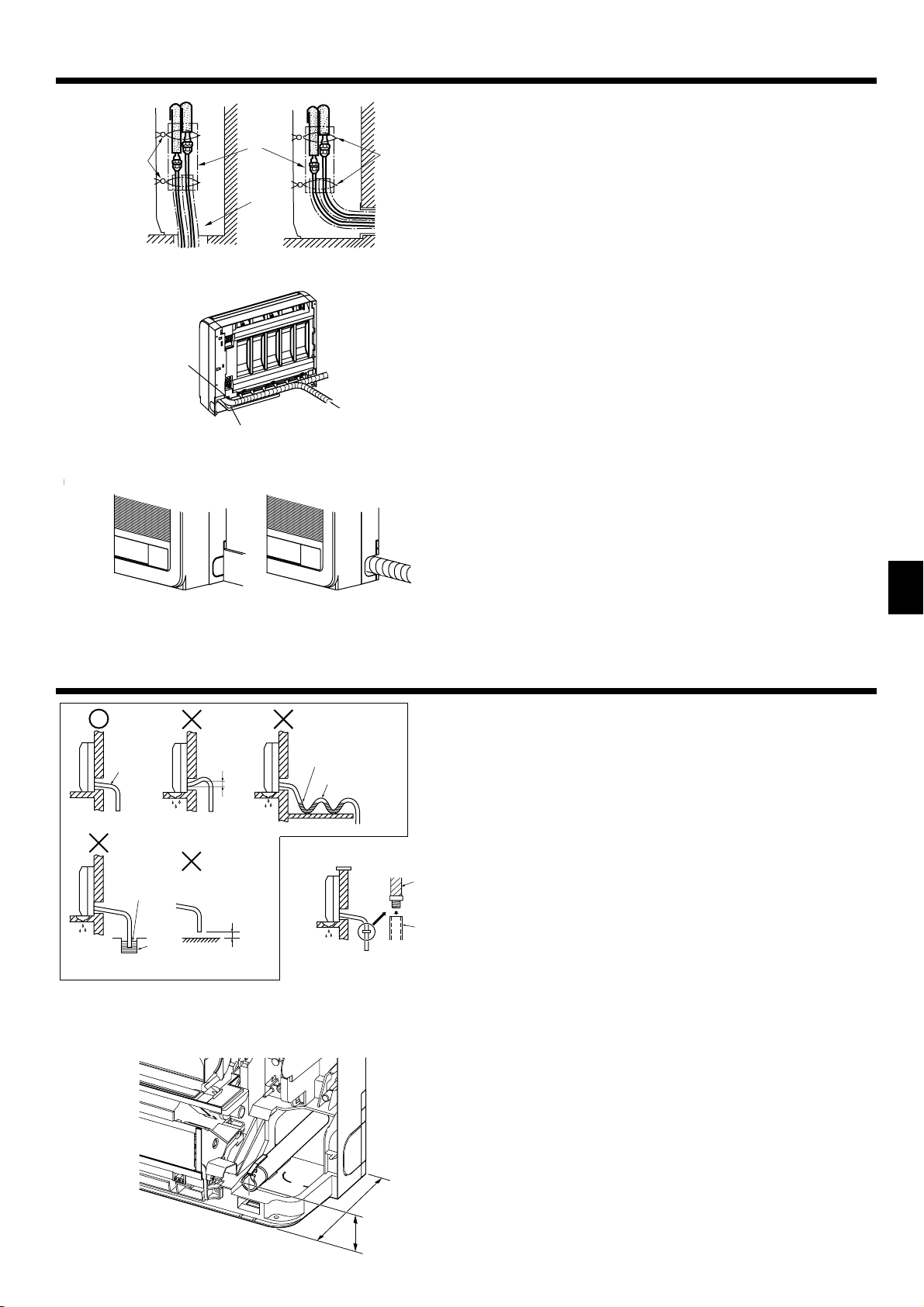
1) For right downward piping (Fig. 4-3)
2) For piping other than right downward (Fig. 4-4)
Bands
A
Pipe covers
B
Remove the cover.
C
• Be sure to insulate the connecting pipes and place them near the rear of the indoor unit so that they do not contact the front panel.
• Be careful not to crush the connecting pipes when bending them.
3) For left or left-rear piping (Fig. 4-5)
Bundle the connecting pipes and drain hose together, and then wrap them in felt
tape.
Make sure that the drain hose is not routed upward.
A
Felt tape
B
* Wrap the felt tape tightly around the pipes and hose starting near where the
pipes and hose are routed from the indoor unit. (The overlap width of the felt
tape should not be more than 1/2 of the tape width.)
Start wrapping the piping tape around the pipes and hose 10 mm inside the
C
indoor unit.
Fasten the end of the felt tape with a bandage stopper.
D
Cut and use the lower side panels on the left and right sides of the indoor unit as
shown.
Smooth the cut edges of the side panels so that they will not damage the insulation
coating. (Fig. 4-6)
Cut the lower side panels to match the height of the modelling.
E
GB
Fig. 4-6
5. Drainage piping work
Fig. 5-1
Fig. 5-2
5.1. Drainage piping work
• Be sure to route the drain piping slightly downward (1/100 or more) so that the
drain water fl ows easily.
• Do not route the drain piping as shown in the examples mark with an “X” in the
fi gure. (Fig. 5-1)
• If the drain hose is too short, refer to Fig. 5-2 to extend the length of the hose.
• If the indoor unit is installed in a high location such as a high-rise apartment,
strong winds may cause the drain water to fl ow back through the drain hose and
leak from the unit. If necessary, contact your nearest Mitsubishi Electric representative for the optional parts to prevent this problem.
• If the drain hose is routed indoors, be sure to wrap it in commercially-available
insulation.
• Do not connect the drain piping directly to a septic tank, sewage tank, etc., where
ammonia gases or hydrogen sulfi de are produced.
• If there is slack in the drain hose or the end of the drain hose is raised up, the
drain water may not fl ow smoothly and some drain water may collect in the hose.
This can lead to a strange sound (burbling) being produced during strong winds
or when a ventilation fan, etc., is used in a residence that is well-sealed. If necessary, contact your nearest Mitsubishi Electric representative for the optional parts
to prevent this problem.
Sloping downward
A
No upward slope
B
Accumulated drain water
C
Air
D
End of drain hose is immersed in water.
E
Drainage channel
F
50 mm or less from ground
G
Drain hose
H
Fixable PVC hose (inner diameter: 15 mm) or rigid PVC pipe (VP-15)
I
• When routing the drain piping, make sure that the drain hose is routed as shown.
(Fig. 5-3)
Fig. 5-3
200
50
5
Page 6

5. Drainage piping work
• Insert the drain hose all the way to the base of the drain pan. (Fig. 5-4) Make sure
that the drain hose is securely caught on the projection in the hole in the drain
pan.
Fig. 5-4
Fig. 5-5
6. Embedding the indoor unit in a wall
GB
52
475
65
Fig. 6-1
• Route the drain hose diagonally below the connecting pipes. (Fig. 5-5)
Piping tape
A
Refrigerant piping
B
Drain hose
C
• Make sure that the drain hose is not routed upward and that there are no waves
in the hose.
• Do not pull the drain hose, and then wrap tape around it.
• Route the piping so that it does not project past the rear of the indoor unit. (Refer
to the fi gure to the left.)
Piping bent outward
D
Push
E
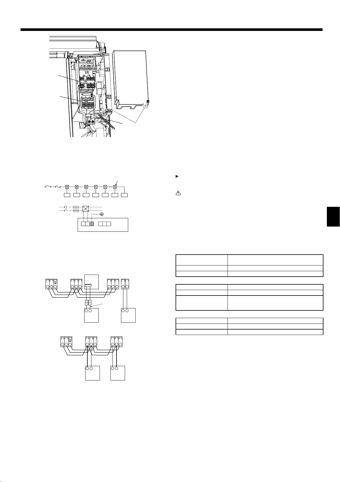
6.1. Embedding the indoor unit in a wall (Fig. 6-1)
• On the indoor unit and right and left space (100 mm or more) are the service
space.
• On a right side of the indoor unit, there is a hole for the room temperature sensor,
and do not close it, please.
• When installing a grating, use a grating with narrow upper and lower horizontal
bars so that the airfl ow from the upper and lower air outlets does not contact the
bars. If the horizontal bars will block the lower air outlet, use a stand, etc., to adjust the height of the indoor unit. If the upper or lower air outlet is blocked, the air
conditioner will not be able to cool or warm the room well.
• Use a grating with vertical bars, etc., that has at least 75% open area. If the grating has horizontal bars or if the open area is less than 75%, performance could
be reduced.
• When the indoor unit is embedded in a wall (built-in), the time it takes for the room
temperature to reach the set temperature will increase.
100 mm or more
A
Upper air outlet
B
Lower air outlet
C
Grating
D
100 mm or more
E
Indoor unit
F
35 mm or more
G
6.2.
Embedded indoor unit setting (must be performed)
(Fig. 6-2)
• When embedding the indoor unit in a wall, restrict the movement of the horizontal
SW3
ON
1234567 8 9 10
Fig. 6-2
vane for the upper air outlet so that it only operates horizontally.
• If this setting is not performed, heat will build up in the wall and the room will not
be cooled or warmed properly.
• Remove the electrical part cover and pull out the control board.
• Set DIP switches 3-5 and 3-6 on the control board to ON.
• After setting the switches, reinstall the control board in its original position and
install the electrical part cover.
Caution:
To avoid damage to the control board due to static electricity, be sure to discharge the static buildup before handling it.
6
Page 7

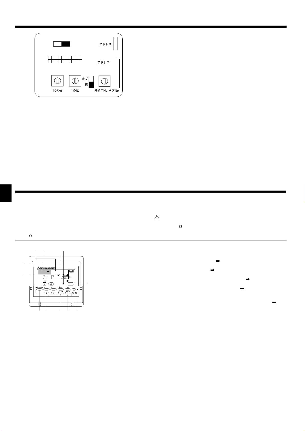
7. Electrical work
Power supply terminal block (TB2)
Transmission terminal block (TB5)
Wiring clamp
Fig. 7-1
7.1. Indoor unit (Fig. 7-1)
Remove the electrical cover.
1
• Remove 1 screw holding the electrical cover, then move the cover.
• Remove 1 screw holding the cord clamp, then move the clamp.
Connect the power line, control line from the outdoor unit, and remote
2
control lines.
After connecting, secure the wires with the cord clamp.
► Fix power source wiring to control box using buffer bushing for tensile
force. (PG connection or the like.)
• Since the electric box may need to be pulled out for servicing or other occasions,
wires must have enough slack.
• Class 3 grounding work must be conducted (grounding wire diameter: 1.6 mm or
more)
After wiring is completed, reinstall the parts in the reverse order of removal.
7.2. Power supply wiring
• Install an earth line longer than other cables.
• Power supply codes of appliance shall not be lighter than design 60245 IEC 53
or 60227 IEC 53.
• A switch with at least 3 mm contact separation in each pole shall be provided by
the air conditioner installation.
Power cable size : more than 1.5mm² (3-core)
M1M2
N
L
TB2 TB5
S
► Use earth leakage breaker (NV).
For breaker, means shall be provided to ensure disconnection of all active phase
conductors of the supply.
Warning:
Wiring should be done so that the power lines are not subject to tension.
Otherwise, heat may be generated or fire may occur.
[Fig. 7-2]
Switch 16 A
A
Overcurrent protection 16 A
B
Indoor unit
C
Total operating current be less than 16 A
D
Pull box
E
GB
Fig. 7-2
M1M2 CN3A
TB3
TB3
Indoor controller board
SM1M2 SM1M2
/
M1M2
SM1M2 SM1M2
TB5 TB5
7.3. Types of control cables
21
51BT5BT5BT
1. Wiring transmission cables
Types of transmission cable Shielding wire CVVS or CPEVS
Cable diameter More than 1.25 mm²
Length Less than 200m
2. M-NET Remote control cables
Types of remote control cable Shielding wire MVVS
Cable diameter 0.5 to 1.25 mm²
Length
3. MA Remote control cables
Types of remote control cable 2-core cable (unshielded)
Cable diameter 0.3 to 1.25 mm²
Length Less than 200m
Add any portion in excess of 10m to within the
longest allowable transmission cable length 200m
Fig. 7-3
7.4. Connecting remote controller, indoor and outdoor
transmission cables (Fig. 7-3)
• Connect indoor unit TB5 and outdoor unit TB3. (Non-polarized 2-wire)
The “S” on indoor unit TB5 is a shielding wire connection. For specifi cations about
the connecting cables, refer to the outdoor unit installation manual.
• Install a remote controller following the manual supplied with the remote control-
ler.
• Connect the remote controller’s transmission cable within 10 m using a 0.75 mm
core cable. If the distance is more than 10 m, use a 1.25 mm
MA Remote controller
1
• Connect the connector for MA remote controller. (Non-polarized 2-wire)
• DC 9 to 13 V between 1 and 2 (MA remote controller)
MA remote controller cable (ACCESSORY 9)
a
M-NET Remote controller
2
• Connect the “M1” and “M2” on indoor unit TB5 to a M-NET remote controller. (Non
-polarized 2-wire)
• DC 24 to 30 V between M1 and M2 (M-NET remote controller)
Terminal block for indoor transmission cable
A
Terminal block for outdoor transmission cable
B
Remote controller
C
2
junction cable.
2
7
Page 8

7. Electrical work
GB
8. Test run
SW5
220V 240V
ON
OFF
SW1
12345678910
SW12
0
1
9
2
8
3
7
4
6
5
(10ths DIGIT)
SW11
0
1
9
2
8
3
7
4
6
5
(1s DIGIT)
Fig. 7-4
SWC
(BRANCH No.)
CN82
SW14
E
D
C
CN43
F
B
A
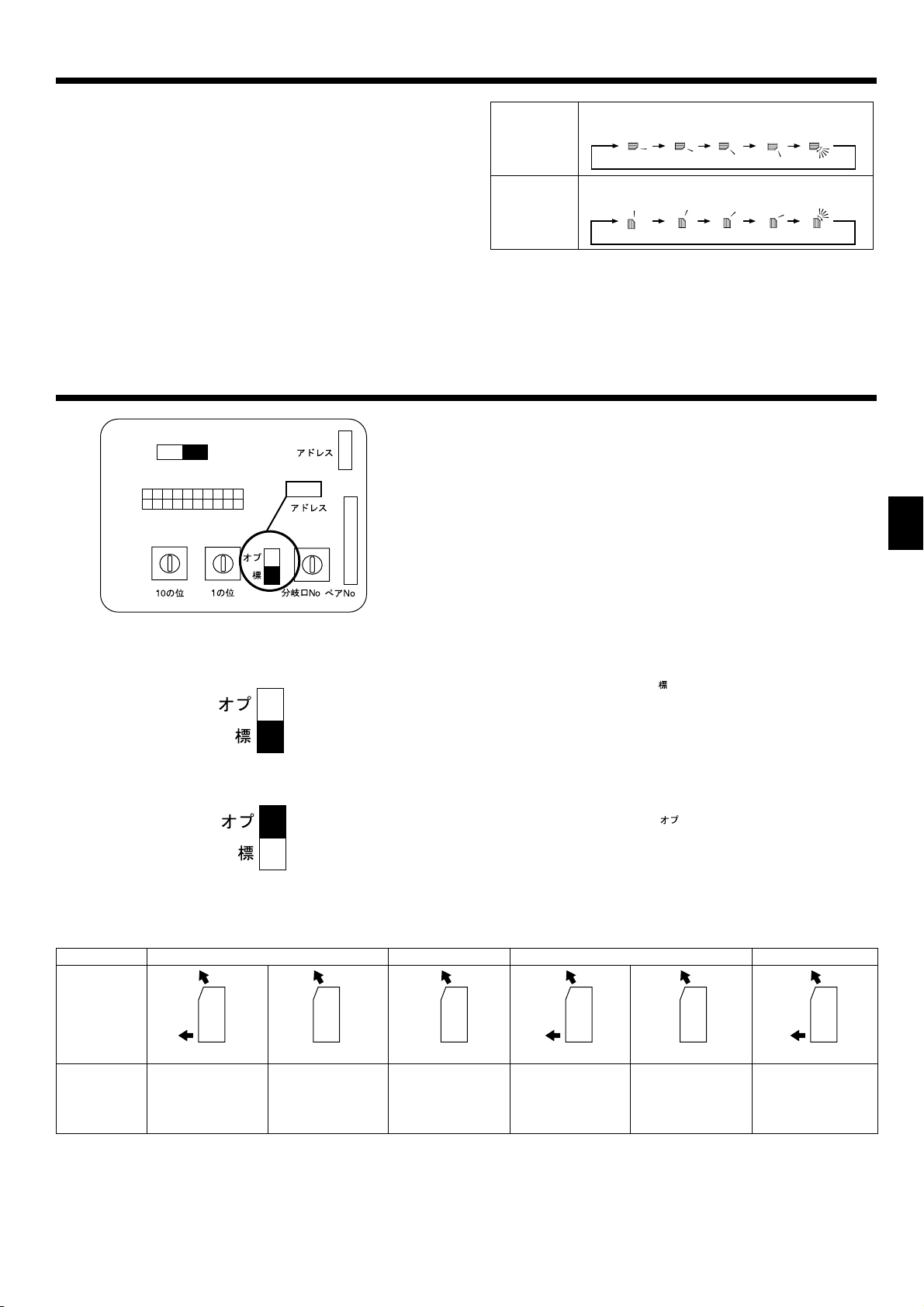
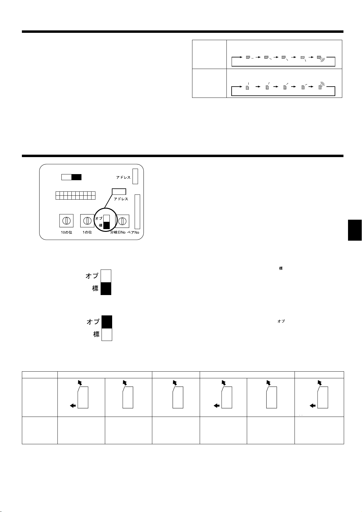
7.5. Setting addresses (Fig. 7-4)
(Be sure to operate with the main power turned OFF.)
• There are 2 types of rotary switch setting available: setting addresses 1 to 9 and
over 10, and setting branch numbers.
How to set addresses
1
Example: If Address is “3”, remain SW12 (for over 10) at “0”, and match
SW11 (for 1 to 9) with “3”.
How to set branch numbers SW14 (Series R2 only)
2
0
1
2
3
4
5
6
7
8
9
./
.
Match the indoor unit’s refrigerant pipe with the BC controller’s end connection
number.
Remain other than series R2 at “0”.
• The rotary switches are all set to “0” when shipped from the factory. These
switches can be used to set unit addresses and branch numbers at will.
• The determination of indoor unit addresses varies with the system at site. Set
them referring to the Data Book.
Note:
Please set the switch SW5 according to the power supply voltage.
• Set SW5 to 240 V side when the power supply is 230 and 240 volts.
• When the power supply is 220 volts, set SW5 to 220 V side.
Address board
A
7.6. Sensing room temperature with the built-in sensor
in a remote controller (Fig.7-4)
If you want to sense room temperature with the built-in sensor in a remote
controller, set SW1-1 on the control board to “ON”. The setting of SW1-7 and
SW1-8 as necessary also makes it possible to adjust the air fl ow at a time when
the heating thermometer is OFF.
8.1. Before test run
► After completing installation and the wiring and piping of the indoor and
outdoor units, check for refrigerant leakage, looseness in the power
supply or control wiring, wrong polarity, and no disconnection of one
phase in the supply.
►
Use a 500-volt megohmmeter to check that the resistance between the
power supply terminals and ground is at least 1.0 M
TEST RUN
COOL, HEAT
MONITOR/SET
BACK DAY
PAR-21MAA
˚C
˚C
TEMP.
MENU
ON/OFF
CLOCK
OPERATION
SIMPLE
ON/OFF
CHECK
CLEAR
FILTER
TEST
"
.
ON/OFF button
Test run display
Indoor liquid pipe
temperature display
ON/OFF lamp
Power display
Error code display
Test run remaining time
display
Set temperature button
Mode selection button
Fan speed button
Air direction button
TEST button
Fig. 8-1
► Do not carry out this test on the control wiring (low voltage circuit)
terminals.
Warning:
Do not use the air conditioner if the insulation resistance is less than 1.0 M
"
.
8.2. Test run (Using wired remote controller) (Fig 8-1)
Turn on the power at least 12 hours before the test run.
1
Press the [TEST] button twice. “TEST RUN” liquid crystal display
2
Press the [Mode selection] button. Make sure that wind is blown out.
3
Press the [Mode selection] button and switch to the cooling (or heating) mode.
4
Make sure that cold (or warm) wind is blown out.
Press the [Fan speed] button. Make sure that the wind speed is switched.
5
Check operation of the outdoor unit fan.
6
Release test run by pressing the [ON/OFF] button. Stop
7
Register a telephone number.
8
The telephone number of the repair shop, sales offi ce, etc., to contact if an error
occurs can be registered in the remote controller. The telephone number will be
displayed when an error occurs. For registration procedures, refer to the operation
manual for the indoor unit.
Note:
• If an error code is displayed on the remote controller or if the air conditioner
does not operate properly, refer to the outdoor unit installation manual or
other technical materials.
• The OFF timer is set for the test run to automatically stop after 2 hours.
• During the test run, the time remaining is shown in the time display.
• During the test run, the temperature of the indoor unit refrigerant pipes is
shown in the room temperature display of the remote controller.
• When the VANE or LOUVER button is pressed, the message “NOT
AVAILABLE” may appear on the remote controller display depending on the
indoor unit model, but this is not a malfunction.
• For the PFFY-P•VKM series, the airfl ow direction displayed on the remote
controller is different from the actual airflow direction. Refer to the
following table.
8
Page 9
8. Test run
9. Air outlet selection
SW5
220V 240V
ON
OFF
SW1
12345678910
SW12
9
8
7
(10ths DIGIT)
SW11
0
6
5
0
1
2
3
4
1
9
2
8
3
7
4
6
5
(1s DIGIT)
SWC
(BRANCH No.)
SWC
CN82
SW14
E
D
C
B
CN43
0
1
F
A
9
Display
Actual
123 4
1234
(Horiz.) Swing
gniwS).ziroH(
• The lower air outlet damper automatically opens and closes according to
the piping temperature, intake air temperature, and operation time. The
airfl ow direction cannot be set.
With this function, air comes out simultaneously from the upper and lower air
outlets so that the room can be cooled or heated effectively. This function is set
using the switch SWC on the address board.
GB
2
3
4
5
6
7
8
./
.
Fig. 9-1
SWC
SWC
Note:
Be sure to operate with the main power turned off.
Description of operation
Operation
Air flow
Conditions
Upper and lower air flow
Room temperature and
set temperature are different.
COOL
Upper air flow
Room temperature is
close toset temperature
or thermo-off.
How to set to blow out air from the upper and lower air outlets:
►
Air blows out automatically from the upper and lower air outlets as shown in the
table below.
How to set to blow out air from the upper air outlet only:
►
DRY
Upper air flow only
—
Set the SWC to lower side (“ ”). (Initial setting)
Set the SWC to upper side (“ ”).
Upper and lower air flow
(Normal condition (in
heating))
Upper air flow
During defrosting operation, start of operation, thermo-off
Upper and lower air flow
NAFTAEH
—
• Be sure to keep the area around the damper of the lower air outlet free of any objects.
9
Page 10

Inhaltsverzeichnis
1. Sicherheitsvorkehrungen ............................................................................. 10
2. Aufstellort..................................................................................................... 10
3. Anbringung der Innenanlage ........................................................................11
4. Kältemittelrohrleitung ................................................................................... 12
5. Verrohrung der Dränage.............................................................................. 13
1. Sicherheitsvorkehrungen
► Vergewissern Sie sich vor dem Einbau der Anlage, dass Sie alle Infor-
mationen über “Sicherheitsvorkehrungen” gelesen haben.
Vor dem Anschließen dieses Gerätes an das Stromnetz Ihr Stromversor-
►
gungsunternehmen informieren oder dessen Genehmigung einholen.
Warnung:
Beschreibt Vorkehrungen, die beachtet werden müssen, um den Benutzer
vor der Gefahr von Verletzungen oder tödlichen Unfällen zu bewahren.
Vorsicht:
Beschreibt Vorkehrungen, die beachtet werden müssen, damit an der Anlage
keine Schäden entstehen.
Erläutern Sie dem Kunden nach Abschluss der Installationsarbeiten die “Sicherheitsvorkehrungen” sowie die Nutzung und Wartung der Anlage entsprechend den
Informationen in der Bedienungsanleitung und führen Sie einen Testlauf durch,
um sicherzustellen, dass die Anlage ordnungsgemäß funktioniert. Geben Sie dem
Benutzer sowohl die Installations- als auch die Bedienungsanleitung zur Aufbewahrung. Diese Anleitungen sind auch den nachfolgenden
Besitzern der Anlage weiterzugeben.
Warnung:
• Bitten Sie Ihren Fachhändler oder einen geprüften Fachtechniker, die Instal-
lation der Anlage vorzunehmen.
• Die Anlage an einer Stelle anbringen, die das Gewicht tragen kann.
• Zur Verdrahtung die angegebenen Kabel verwenden.
D
• Nur von Mitsubishi Electric zugelassenes Zubehör verwenden, und dieses
durch Ihren Händler oder eine Vertragswerkstatt einbauen lassen.
• Nicht die Wärmetauscherleitung berühren.
Die Anlage gemäß Anweisungen in diesem Installations-handbuch installieren.
•
Vorsicht:
• Bei Verwendung des Kältemittels R410A oder R407C die vorhandene Kälte-
mittelrohrleitung nicht benutzen.
•
Bei Verwendung des Kältemittels R410A oder R407C Ester-Öl, Äther-Öl oder Alkylbenzin
(geringe Mengen) zum Beschichten der Konus- und Flanschanschlüsse verwenden.
• Anlage nicht an Orten verwenden, wo sich Lebensmittel, Tiere, Pfl anzen,
Präzisionswerkzeuge oder Kunstgegenstände befi nden.
• Anlage nicht unter besonderen Umfeldbedingungen einsetzen.
2. Aufstellort
6. Wandeinbau der Innenanlage ..................................................................... 14
7. Elektroarbeiten ............................................................................................ 15
8. Testlauf ........................................................................................................ 16
9. Luftauslass .................................................................................................. 17
: Beschreibt eine Handlung, die unterbleiben muss.
: Zeigt an, dass wichtige Anweisungen zu befolgen sind.
: Verweist auf einen Teil der Anlage, der geerdet werden muss.
: Zeigt an, dass bei rotierenden Teilen Vorsicht geboten ist.
: Zeigt an, dass vor Beginn der Wartungsarbeiten der Hauptschalter ausge-
schaltet werden muss.
: Gefahr von elektrischem Schlag.
: Verbrennungsgefahr.
: Bei der Wartung bitte Netzstrom sowohl für die Innen- als auch für die Au-
ELV
ßenanlage abschalten.
Warnung:
Sorgfältig die auf der Hauptanlage aufgebrachten Aufschriften lesen.
• Alle Elektroarbeiten müssen entsprechend den örtlichen Vorschriften von
zugelassenen Fachelektrikern ausgeführt werden.
• Wenn die Anlage in einem kleinen Raum installiert wird, müssen Maßnahmen ergriffen werden, damit die Kältemittelkonzentration auch bei Kältemittelaustritt den Sicherheitsgrenzwert nicht überschreitet.
• Die Schnittstellen der gestanzten Teile können Schnittverletzungen verursachen. Daher sind die Installateure aufgefordert, Schutzkleidung wie etwa
Handschuhe, zu tragen.
• Erdung der Anlage.
• Einen Fehlerstromschutzschalter wie vorgesehen anbringen.
•
Netzstromkabel mit ausreichender Stromstärke und Nennwertauslegung verwenden.
• Nur Stromunterbrecher und Sicherungen der angegebenen Leistung verwenden.
• Schalter nicht mit nassen Fingern berühren.
•
Kältemittelrohrleitung nicht während oder unmittelbar nach Betrieb berühren.
• Klimageräte nicht bei abgenommenen Verkleidungen und Schutzabdeckungen betreiben.
• Netzstrom nicht unmittelbar nach Betriebsbeendigung ausschalten.
10
(mm)
200
700
A
B
600
Zum Lieferumfang der Innenanlage gehört folgendes Sonderzubehör.
TEILENUMMER
1
2
3
4
5
6
7
8
9
Auslaufschlauch 1
Rohrisolation 1
Band 2
Montagehalterung für Innenanlage 1
Befestigungsschraube für 4 4 × 25 mm 5
Holzschraube für Befestigung der Innenanlage
Unterlegscheibe von
Filzband (verwendet für Verrohrung links oder links hinten)
Kabel der MA-Fernbedienung 1
ZUBEHÖR MENGE
6
4
4
1
2.1. Außenabmessungen (Innenanlage) (Fig. 2-1)
C
D
Fig. 2-1
Das Gerät muss sicher und fest auf einem Untergrund befestigt werden, der dessen Gewicht tragen kann.
Modelle A B C D
P20/25/32/40
Warnung:
Die Innenanlage an einer Wand montieren, die stark genug ist, um das Gewicht der Anlage zu tragen.
100 mm oder
mehr
100 mm oder
mehr
100 mm oder
mehr
150 mm oder
weniger vom Boden
Page 11
3. Anbringung der Innenanlage
200
131
(700)
Fig. 3-1
Fig. 3-3
131
14
586
(600)
674
Fig. 3-2
Fig. 3-4
(mm)
3.1. Installation der Montagehalterung für Innenanlage
• Die Halterung fest an der Wandstruktur (Bolzen usw.) installieren. (Fig. 3-1)
• Die Montagehalterung mit Hilfe einer Wasserwaage waagerecht installieren.
• Die Innenanlage höchstens 150 mm vom Boden entfernt installieren.
Montagehalterung für Innenanlage
A
Hinweis:
Um ein Vibrieren der Montagehalterung der Innenanlage zu vermeiden, sicherstellen, dass die Halterung an den mit markierten Bohrungen befestigt
wird. Falls möglich, die Halterung zusätzlich an den mit
rungen befestigen. (Fig. 3-2)
markierten Boh-
3.2. Vorbereitung der Innenanlage
Die von den Pfeilen angezeigten 2 Positionen eindrücken, um das Frontgitter
1
zu öffnen. (Fig. 3-3)
Das Frontgitter öffnen und die beiden Schrauben entfernen.
2
Den horizontalen Flügel für den oberen Luftauslass öffnen, das Kopfende der
3
Frontplatte an drei Stellen nach unten drücken und dann das Gitter am Kopfende von der Innenanlage abziehen.
Schrauben
B
Das Frontgitter anheben und entfernen. (Fig. 3-4)
4
3.3. Aufstellung der Innenanlage (Fig. 3-5)
•
Das Kopfende der Innenanlage in die Montagehalterung für Innenanlage einhaken.
• Die mitgelieferten Holzschrauben und Unterlegscheibe verwenden, und die In-
nenanlage an 2 Stellen ( ) jeweils oben und in der Mitte des Geräts befestigen.
D
Hinweis:
Montieren Sie die Innenanlage sicher und fest an der Wand, und achten Sie
darauf, dass kein Spalt zwischen Gerät und Wnad verbleibt.
363
333210
Fig. 3-5
Fig. 3-6
1)
131
14
600
700
288
131
496
97
80
3.4. Bohrungen in Wand und Boden
3.4.1. Löcher bohren (Fig. 3-6)
Bohren Sie Löcher von ø 65 mm oder ø 75 mm von etwa 5–7 mm Tiefe und
1
leicht abwärts zum Raum geneigt.
Die Wanddurchbruchhülsen in die Bohrungen einsetzen.
2
Wanddurchbruch
A
65 mm oder 75 mm Durchmesser.
B
Innenseite
C
Querschnitt des Wanddurchbruchs
D
Wanddicke
E
Eine Maßstabteilung
F
Mit einer zusätzlichen Maßstabteilung abschneiden.
G
Wanddurchbruchhülse
H
Vorsicht:
Unbedingt die Wanddurchbruchhülsen verwenden. Anderenfalls könnte eine
äußerst gefährliche Situation entstehen, und zwar durch möglichen Kontakt
der Verbindungskabel des Innen-/Außengeräts mit Metallteilen in der Wand
oder bei hohlen Wänden durch Annagen der Drähte durch kleine Nagetiere.
3.4.2. Positionen der Bohrungen bestimmen
Die Bereiche für die Verlegung der Rohre werden in der Abbildung mit Schrägstrichen angezeigt.
1) Verrohrung hinten oder links hinten (Fig. 3-7)
(Die folgende Abbildung zeigt den Installationsort der Innenanlage von vorne.)
599
Fig. 3-7
2378
11
Page 12
3. Anbringung der Innenanlage
2)
60
200
150
168
700
61
75
62
(mm)
31
73
105
147
2) Verrohrung rechts abwärts oder links abwärts (Fig. 3-8)
(Die folgende Abbildung zeigt den Boden der Innenanlage von oben.)
Bei Wandinstallation des Geräts.
A
Bei Bodeninstallation des Geräts.
B
Fig. 3-8
3)
60
19
60
Fig. 3-9
4)
60
Fig. 3-10
19 60
3) Verrohrung links (Fig. 3-9)
4) Verrohrung rechts (Fig. 3-10)
3.4.3. Abdichtung der Bohrungen
Die Bohrungen mit Dichtungskitt oder einer Dichtmasse abdichten.
4. Kältemittelrohrleitung
D
±0,5°
°
90
øA
45°±2°
R0,4 ~ R0,8
Fig. 4-1
Größen der Kältemittelrohre & Anzugsdrehmoment für Konusmutter
B
Flüssigkeitsrohrleitung Gasrohrleitung Flüssigkeitsrohrleitung Gasrohrleitung
Rohrgröße
(mm)
P20/25/32/40
Tragen Sie Kältemaschinenöl auf die gesamte Konusaufl agefl äche auf.
C
* Tragen Sie kein Kältemaschinenöl an den Schraubenbereichen auf. (Dies bewirkt, dass die Bördelmuttern sich eher lösen.)
Achten Sie darauf, die an der Haupteinheit angebrachten Bördelmuttern zu verwenden.
D
O.D. ø6,35 (1/4”)
Anzugsdreh-
R407C oder R22 R410A
moment
(N·m)
14 - 18
Rohrgröße
(mm)
O.D. ø12,7 (1/2”)
Anzugsdreh-
moment
(N·m)
49 - 61
4.1. Rohranschlüsse (Fig. 4-1)
• Wenn im Handel erhältliche Kupferrohre verwendet werden, Flüssigkeits- und
Gasrohre mit im Handel erhältlichem Isoliermaterial (Hitzebeständig bis 100 °C
und mehr, Stärke 12 mm oder mehr) umwickeln.
• Die in der Anlage befi ndlichen Teile der Ablassrohre sollten mit Isoliermaterial aus
Schaumstoff (spezifi sches Gewicht 0,03 - 9 mm oder stärker) umwickelt werden.
• Vor dem Anziehen der Konusmutter eine dünne Schicht Kältemittel-Öl auf das
Rohr und auf die Oberfl äche des Sitzes an der Nahtstelle auftragen.
• Mit zwei Schraubenschlüsseln die Rohrleitungsanschlüsse fest anziehen.
• Die Anschlüsse der Innenanlage mit dem mitgelieferten Isoliermaterial für die
Kältemittelrohrleitung isolieren. Beim Isolieren sorgfältig vorgehen.
Abmessungen der Aufweitungsschnitte
A
Rohrgröße
O.D. ø6,35 (1/4”)
(Bei Verwendung handelsüblicher Produkte kann es zu Rissbildungen kommen.)
(mm)
Kupferrohr O.D.
(mm)
ø6,35 8,7 - 9,1
ø9,52 12,8 - 13,2
ø12,7 16,2 - 16,6
ø15,88 19,3 - 19,7
ø19,05 23,6 - 24,0
Anzugsdreh-
moment
(N·m)
14 - 18
O.D. ø12,7 (1/2”)
Rohrgröße
(mm)
Aufweitungsabmessungen
øA Abmessungen (mm)
Konusmutter O.D.
Anzugsdreh-
moment
(N·m)
49 - 61 17 26
Flüssig-
keitsrohrlei-
tung
(mm)
Gasrohrlei-
tung
(mm)
12
4.2. Rohrleitungen für Kältemittel
4.2.1. Verlegung der Anschlussrohre
Die Anschlussrohre so installieren, dass sich die Leitungen leicht nach vorne,
hinten, links und rechts bewegen lassen. (Fig. 4-2)
Fig. 4-2
Page 13
4. Kältemittelrohrleitung
Bündig gegen eine Wand mit
Profi lleiste installieren
Für Verrohrung links oder rechts
Fig. 4-3
3)
Bündig gegen eine Wand mit
Installing flushagainst a wall with
Profi lleiste installieren
molding
2)1)
Fig. 4-4
Fig. 4-5
Für Verrohrung links oder rechts
For left or right piping
1) Verrohrung rechts abwärts (Fig. 4-3)
2) Sonstige Verrohrung (Fig. 4-4)
Bänder
A
Rohrisolationen
B
Die Isolation entfernen.
C
• Die Anschlussrohre isolieren und an der Rückseite der Innenanlage verlegen, damit sie nicht mit der Frontplatte in Berührung kommen.
• Darauf achten, dass die Anschlussrohre beim Biegen nicht gequetscht werden.
3) Verrohrung links oder links hinten (Fig. 4-5)
Die Anschlussrohre und den Ablassschlauch zusammen bündeln und mit Filzband
umwikkeln.
Sicherstellen, dass der Ablassschlauch nicht mit Aufwärtsneigung verlegt wird.
A
B Filzband
* Das Filzband fest um die Rohre und den Schlauch wickeln; dabei an der
Stelle beginnen, wo Rohre und Schlauch von der Innenanlage her verlegt
werden. (Die Überlappungsbreite des Filzbandes sollte nicht mehr als 1/2 der
Bandbreite betragen.)
C 10 mm innerhalb der Innenanlage mit dem Umwickeln der Rohre und des
Schlauchs mit Hilfe des Rohrleitungsbandes beginnen.
Eine Bandsicherung am Ende des Filzbandes anbringen.
D
Die Platten der Innenanlage unten links und rechts wie in der Abbildung gezeigt
ausschneiden.
Die Schnittkanten der Seitenplatten abrunden, damit sie die Isolierung nicht beschädigen können. (Fig. 4-6)
Die Platten an der Unterseite in Höhe der Profi lleiste ausschneiden.
E
Fig. 4-6
5. Verrohrung der Dränage
Fig. 5-1
Fig. 5-2
200
5.1. Verrohrung der Dränage
• Achten Sie darauf, das Ablassrohr mit einem Gefälle von 1% oder mehr abwärts
zu verlegen, damit das Wasser ungehindert ablaufen kann.
• Führen Sie den Ablassschlauch nicht so wie in den mit “X” markierten Beispielen
gezeigt (Fig. 5-1)
• Wenn der Ablassschlauch zu kurz ist, beachten Sie Fig. 5-2, wie der Schlauch
verlängert werden kann.
• Falls die Innenanlage in der Wohnung eines Hochhauses installiert wurde, könnte
das Ablaufwasser aufgrund starker Winde durch den Ablassschlauch zurückfl ie-
ßen und aus dem Gerät ablaufen. Um dieses Problem zu beheben, gegebenenfalls einen Mitsubishi- Händler in Ihrer Nähe für eventuelle Zusatzteile kontaktieren.
• Wenn der Ablassschlauch im Raum verlegt wird, darauf achten, dass er mit einer
handelsüblichen Isolierung umwickelt wird.
• Das Ablassrohr nicht direkt an eine Klärgrube usw. anschließen, da dort Ammoni-
akgase oder Schwefelwasserstoffe erzeugt werden.
• Wenn der Ablassschlauch durchhängt oder das Ende des Ablassschlauchs ange-
hoben ist, fl ießt das Ablaufwasser möglicherweise nicht gut ab und könnte sich
im Schlauch ansammeln. Dies könnte zu merkwürdigen Geräuschen (Gluckern,
Heulen) führen, die durch starke Winde erzeugt werden, oder wenn ein Lüfter
o.ä. in einer gut abisolierten Wohnung betrieben wird. Um dieses Problem zu
beheben, gegebenenfalls einen Mitsubishi-Händler in Ihrer Nähe für eventuelle
Zusatzteile kontaktieren.
Abwärts geneigt
A
Nicht ansteigend
B
Angesammeltes Ablaufwasser
C
Luft
D
Ende des Ablassschlauches in Wasser eingetaucht.
E
Ablasskanal
F
Abstand 50 mm oder weniger vom Boden aus
G
Abfl ussleitung
H
Montierbarer PVC-Schlauch (Innendurchmesser: 15 mm) oder Hart-PVC-Rohr (VP-15)
I
• Bei Verlegen des Ablassrohres sicherstellen, dass der Ablassschlauch wie abge-
bildet verlegt wird. (Fig. 5-3)
D
Fig. 5-3
50
13
Page 14
5. Verrohrung der Dränage
• Den Ablassschlauch entlang der Ablaufwanne verlegen. (Fig. 5-4)
Sicherstellen, dass der Ablassschlauch fest auf der Nase in der Bohrung der Ablaufwanne sitzt.
Fig. 5-4
Fig. 5-5
6. Wandeinbau der Innenanlage
D
52
475
65
Fig. 6-1
• Den Ablassschlauch diagonal unter den Anschlussrohren verlegen. (Fig. 5-5)
Rohrleitungsband
A
Kältemittelleitung
B
Ablassschlauch
C
• Sicherstellen, dass der Ablassschlauch nicht mit Aufwärtsneigung verlegt wird
und dass keine Wellen im Schlauch sind.
• Auf keinen Fall am Ablassschlauch ziehen; Band um den Schlauch wickeln.
• Die Rohrleitung so verlegen, dass sie nicht an der Rückseite der Innenanlage
herausragt. (Beachten Sie die Abbildung links.)
Nach außen gebogene Leitung
D
Andrücken
E
6.1. Wandeinbau der Innenanlage (Fig. 6-1)
• Bei der Innenanlage dient der Platz links und rechts vom Gerät (100 mm oder
mehr) als Platz für Wartungsarbeiten.
• An der rechten Seite der Innenanlage befi ndet sich eine Öffnung für den Tempe-
ratursensor, die Sie bitte nicht verschließen sollten.
• Bei Einbau eines Gitters sollte dieses obere und untere, schmale, horizontale
Leisten aufweisen, damit die Luft unbehindert aus dem Luftauslass oben und
unten strömen kann. Wenn die horizontalen Leisten den unteren Luftauslass versperren, einen Sockel verwenden, um die Höhe der Innenanlage zu regulieren.
Wenn der obere oder untere Luftauslass versperrt ist, kann die Klimaanlage den
Raum nicht mehr richtig heizen oder kühlen.
• Ein Gitter mit vertikalen Leisten usw. verwenden, die mindestens 75% offene Flä-
che bieten. Bei einem Gitter mit horizontalen Leisten oder einer offenen Fläche
von weniger als 75% könnte die Leistung stark beeinträchtigt werden.
• Bei einer in die Wand eingebauten Innenanlage verlängert sich die Zeit, die zum
Erreichen der eingestellten Raumtemperatur benötigt wird.
100 mm oder mehr
A
Oberer Luftauslass
B
Unterer Luftauslass
C
Gitter
D
100 mm oder mehr
E
Innenanlage
F
35 mm oder mehr
G
14
SW3
ON
1234567 8 9 10
Fig. 6-2
6.2.
Einstellung der eingebauten Innenanlage (zwin-
gend)
• Bei Einbau der Innenanlage in die Wand die Bewegung des horizontalen Flügels
auf den oberen Luftauslass begrenzen, so dass er nur horizontal arbeitet.
• Falls diese Einstellung nicht vorgenommen wird, staut sich die Wärme in der
Wand, und der Raum wird nicht richtig gekühlt oder geheizt.
• Entfernen Sie die Abdeckung der Elektronik und ziehen Sie die Steuerungsplatine
heraus.
• Stellen Sie die DIP-Schalter 3-5 und 3-6 auf der Steuerungsplatine auf ON (ein-
geschaltet).
• Nach Einstellung der DIP-Schalter stecken Sie die Steuerungsplatine an die ur-
sprüngliche Position und setzen Sie die Abdeckung der Elektronik wieder auf.
Vorsicht:
Um Schäden an der Elektronik aufgrund von statischer Elektrizität zu vermeiden, leiten Sie eventuelle statische Aufl adungen ab, bevor Sie die Baugruppe
berühren.
(Fig. 6-2)
Page 15
7. Elektroarbeiten
7.1. Innenanlage (Fig. 7-1)
Entfernen Sie die Abdeckung der Elektronik.
1
• Entfernen Sie die Schraube, die die Abdeckung der Elektronik hält, und nehmen
Sie dann die Abdeckung ab.
• Entfernen Sie die Schraube, die die Kabelklemme hält, und entfernen Sie dann
die Klemme.
Anschlussleiste für Stromversorgung (TB2)
A
Power supply terminal block (TB2)
Anschlussleiste der Übertragung (TB5)
B
Outdoor unit terminal block (TB5)
Elektroklemme
c
Wiring clamp
Fig. 7-1
N
L
TB2 TB5
M1M2
Schließen Sie die Netzleitung, die Steuerleitung von der Außenanlage und
2
die Leitungen der Fernbedienung an.
Nach dem Anschließen sichern Sie bitte die Leitungen mit Kabelband.
► Netzstromverdrahtung zum Schaltkasten mit Pufferdurchführung für Span-
nungskräfte (PG-Anschluss oder Ähnliches) befestigen.
• Da der Elektroanschlusskasten zur Wartung oder bei anderen Gelegenheiten herausgezogen werden muss, müssen die Drähte genügend Spiel besitzen.
•
Erdung der Klasse 3 muss durchgeführt werden (Erdleitungsgröße: 1,6 mm oder mehr).
Nach Abschluss der Verdrahtung die abgenommenen Teile in umgekehrter Rei-
henfolge wieder anbringen.
7.2. Stromversorgungskabel
• Es ist eine Erdungsleitung zu installieren, die länger als andere Leitungen ist.
• Die Stromversorgung muss mindestens den Normen 60245 IEC 53 oder 60227
IEC 53 entsprechen.
• Ein Schalter mit einem Kontaktabstand von mindestens 3 mm muss bei der In-
stallation der Klimaanlage verwendet werden.
Aderdurchmesser Stromversorgungskabel: größer als 1,5 mm². (3-adrige)
Verwenden Sie einen Fehlerstromschutzschalter (NV).
Beim Trennschalter sind Mittel vorzusehen, um eine Trennung aller stromführenden
Warnung:
Bei der Verdrahtung dürfen die Strom führenden Kabel keinem mechanischen
Zug unterliegen. Widrigenfalls kann es zu Überhitzung kommen, oder es
kann Feuer ausbrechen.
[Fig. 7-2]
Schalter 16 A
S
A
Überstromschutz 16 A
B
Innenanlage
C
Gesamtbetriebsstrom < 16 A
D
Einziehdose
E
D
Fig. 7-2
Steuerungsplatine der Innenanlage
M1M2 CN3A
TB3
TB3
Indoor controller board
SM1M2 SM1M2
/
M1M2
SM1M2 SM1M2
TB5 TB5
21
51BT5BT5BT
7.3. Steuerkabelarten
1. Übertragungskabel für die Verdrahtung
Arten von Übertragungs-
kabeln
Kabeldurchmesser Mehr als 1,25 mm²
Länge Weniger als 200 m
2. M-NET Fernbedienungskabel
Kabelarten Abgeschirmte Elektroleitungen MVVS
Kabeldurchmesser 0,5 bis 1,25 mm²
Länge
3. MA Fernbedienungskabel
Kabelarten Umhüllte, 2-adrige Leitung (nicht abgeschirmt)
Kabeldurchmesser 0,3 bis 1,25 mm²
Länge Weniger als 200 m
Abgeschirmte Elektroleitungen CVVS oder CPEVS
Beliebige Stücke von mehr als 10 m bis zu der
größten, zulässigen Übertragungskabellänge
von 200 m hinzufügen
7.4. Anschluss der Fernbedienungs-, Innen- und Au-
ßenübertragungskabel (Fig. 7-3)
• Anschluss der Innenanlage TB5 und der Außenanlage TB3. (2-adrig, nichtpolari-
siert) Das “S” auf der Innenanlage TB5 ist ein abgeschirmter Leitungsanschluss.
Angaben über die technischen Daten der Anschlusskabel fi nden sich in den Mon-
tagehandbüchern der Außenanlage.
Fig. 7-3
• Eine Fernbedienung entsprechend den Angaben im zur Fernbedienung gehö-
renden Handbuch installieren.
•
Das Übertragungskabel der Fernbedienung mit einem Kernaderkabel von 0,75 mm
und einer Länge bis zu 10 m anschließen. Wenn die Entfernung mehr als 10 m
beträgt, ein Verbindungskabel von 1,25 mm
MA-Fernbedienung
1
• Den Stecker der MA-Fernbedienung anschließen (2-adrig, nichtpolarisiert).
• 9 bis 13 V Gleichstrom zwischen 1 und 2 (MA-Fernbedienung)
Kabel der MA-Fernbedienung (ZUBEHÖR 9)
a
M-NET-Fernbedienung
2
• “M1” und “M2” am TB5 der Innenanlage an eine M-NET-Fernbedienung anschlie-
ßen (2- adrig, nichtpolarisiert).
• 24 bis 30 V Gleichstrom zwischen M1 und M2 (M-NET-Fernbedienung)
Klemmleiste für Übertragungskabel der Innenanlage
A
Klemmleiste für Übertragungskabel der Außenanlage
B
Fernbedienung
C
2
verwenden.
2
15
Page 16
7. Elektroarbeiten
ON
OFF
SW5
220V 240V
SW1
12345678910
SW12
9
8
7
(10ths DIGIT)
SW11
0
1
9
2
8
3
7
4
6
6
5
(1s DIGIT)
CN43
CN82
SW14
SWC
0
1
2
3
4
5
0
1
F
2
3
E
4
D
5
C
6
B
7
A
8
9
./
(BRANCH No.)
.
7.5. Adressen einsetzen (Fig. 7-4)
(Dafür sorgen, daß bei den Arbeiten der Netzstrom auf AUS geschaltet ist.)
•
Zur Einstellung gibt es zwei Arten von Rotationsschaltern: Zur Einstellung der
Adressen von 1 bis 9 und über 10 sowie zur Einstellung der Abzweigungsnummern.
Wie stellt man Adressen ein
1
Beispiel: Wenn die Adresse ’3’ ist, SW12 (für größer als 10) bei ’0’ lassen und
SW11 (für 1 – 9) auf ’3’ einstellen.
Einstellen der Zweignummern SW14 (nur Serie R2)
2
Die Zweignummer für jedes Innengerät ist gleichzeitig die Anschlussnummer
des BC-Controllers, an dem das Innengerät angeschlossen ist.
Lassen Sie dies bei Geräten, die nicht zur Reihe R2 gehören, auf „0“ eingestellt.
• Die Drehschalter sind bei Versand ab Werk alle auf “0” eingestellt.
Diese Schalter können beliebig zur Einstellung der Anlagenadressen und Abzweignummern verwendet werden.
• Die Festlegung der Adressen der Innengeräte variiert mit der Anlage vor Ort.
Fig. 7-4
Stellen Sie diese mithilfe des Datenheftes (Data Book) ein.
Hinweis:
Bitte den Schalter SW5 je nach Netzspannung einstellen:
• Bei Netzspannung von 230 V and 240 V Schalter SW5 auf die Seite 240 V
einstellen.
• Bei Netzspannung von 220 V Schalter SW5 auf die Seite 220 V einstellen.
Adressentafel
A
7.6.
Messen der Raumtemperatur mit dem in eine Fern-
bedienung eingebauten Temperaturfühler (Fig.7-4)
Wenn Sie die Raumtemperatur mit dem in eine Fernbedienung eingebauten Fühler
messen wollen, stellen Sie den Schalter SW1-1 auf der Schalttafel auf ’ON’/ ’EIN’.
Die Einstellung von SW1-7 und SW1-8 ermöglicht es auch, der Luftdurchsatz einzustellen für Phasen, in denen das Heizthermometer ausgeschaltet ist (OFF).
8. Testlauf
D
8.1. Vor dem Testlauf
► Nach Installierung, Verdrahtung und Verlegung der Rohrleitungen der In-
nen- und Außenanlagen überprüfen und sicherstellen, dass kein Kältemittel ausläuft, Netzstromversorgung und Steuerleitungen nicht locker sind,
Polarität nicht falsch angeordnet und keine einzelne Netzanschlussphase
getrennt ist.
►
Mit einem 500-Volt-Megohmmeter überprüfen und sicherstellen, dass der
Widerstand zwischen Stromversorgungsklemmen und Erdung mindestens
1,0 M beträgt.
Taste ON/OFF
A
TEST RUN
COOL, HEAT
˚C
TEMP.
MENU
MONITOR/SET
BACK DAY
PAR-21MAA
CLOCK
ON/OFF
˚C
OPERATION
SIMPLE
ON/OFF
FILTER
CHECK
TEST
CLEAR
Fig. 8-1
ON/OFF button
Testlaufanzeige
B
Test run display
Temperaturanzeige der Flüs-
C
Indoor liquid pipe
sigkeitsleitung der Innenanlage
temperature display
Lampe ON/OFF
D
ON/OFF lamp
Bereitschaftsanzeige
E
Power display
Fehlercodeanzeige Anzeige
F
Error code display
der verbleibenden Testlaufzeit
Test run remaining time
Temperaturwahltaste
G
display
Betriebsartwahltaste
H
Set temperature button
Gebläsegeschwindigkeitstaste
I
Mode selection button
Luftrichtungstaste
J
Fan speed button
Taste TEST
M
Air direction button
TEST button
► Diesen Test nicht an den Klemmen der Steuerleitungen (Niederspannungs-
stromkreis) vornehmen.
Warnung:
Die Klimaanlage nicht in Betrieb nehmen, wenn der Isolationswiderstand weniger als 1,0 M beträgt.
Isolationswiderstand
8.2. Testlauf
Verwendung der verdrahteten Fernbedienung (Fig. 8-1)
Den Strom mindestens 12 Stunden vor dem Testlauf einschalten.
1
Die [TEST]-Taste zweimal drücken.
2
Taste [Mode selection] (Wahl der Betriebsart) drücken und die Betriebsart Küh-
3
len (oder Heizen) einschalten. Vergewissern, daß kalte (oder warme) Luft
ausgeblasen wird.
Die Taste [Fan speed] (Luftgeschwindigkeit) drücken.
4
Luftgeschwindigkeit eingeschaltet ist.
Die Luftrichtungs- oder die Jalousietaste drücken.
5
der Jalousie kontrollieren.
Den Betrieb des Gebläses der Außenanlage überprüfen.
6
Durch Drücken der Taste [ON/OFF] (EIN/AUS) den Testlauf freigeben. Stopp
7
Speichern Sie eine Telefonnummer ein.
8
Die Telefonnummer eines Reparaturbetriebs, Verkaufsbüros usw. kann für eine
Kontaktaufnahme bei auftretenden Fehlern in die Fernbedienung eingespeichert
werden. Die Telefonnummer wird angezeigt, wenn ein Fehler aufgetreten ist.
Für Anweisungen für die Eingabe dieser Nummer lesen Sie die Bedienungsan-
leitung des Innengerätes.
“TEST RUN”-Flüssigkristallanzeige (LCD)
Vergewissern, daß die
Funktion des Flügels bzw.
Hinweis:
• Wenn auf der Fernbedienung ein Fehlercode angezeigt wird oder wenn die Klimaanlage nicht ordnungsgemäß arbeitet, schlagen Sie bitte im Installationshandbuch oder sonstigen technischen Unterlagen der Außenanlage nach.
• Der OFF-Timer (Ausschaltzeitschalter) ist für den Testlauf auf automatisches Ausschalten nach 2 Stunden eingestellt.
• Während des Testlaufs wird die Restzeit auf der Zeitanzeige angezeigt.
• Während des Testlaufs wird die Temperatur der Kältemittelrohrleitungen der Innenanlage auf der Raumtemperaturanzeige der Fernbedienung angezeigt.
• Wenn die Taste VANE (Luftklappe) oder LOUVER (Luftleitlamellen) gedrückt wird, kann, je nach Modell der Innenanlage, auf der Anzeige der Fernbedienung
die Meldung “NOT AVAILABLE (nicht verfügbar)” erscheinen, aber dies ist keine Fehlfunktion.
• Bei Geräten der Serie PFFY-P·VKM weicht die auf der Fernbedienung angezeigte Luftstromrichtung von der tatsächlichen Luftstromrichtung ab. Beachten Sie
hierzu folgende Tabelle.
16
Page 17
8. Testlauf
9. Luftauslass
SW5
220V 240V
ON
OFF
12345678910
SW12
0
9
8
7
6
5
(10ths DIGIT)
Display
Anzeig
Actual
Aktuell
123 4
(Horiz.)
1234
Schwing
(Horiz.)
Schwing
(Horiz.) Swing
gniwS).ziroH(
• Die Luftstromrichtung des Dämpfer des unteren Luftauslasses lässt sich
nicht einstellen. Die Luftstromrichtung wird automatisch über einen Computer geregelt.
Mit dieser Funktion strömt die Luft gleichzeitig aus den oberen und unteren
Luftauslässen, so dass der Raum effektiver gekühlt oder geheizt werden kann. Di-
CN43
SW1
SW11
0
1
2
3
4
1
9
2
8
3
7
4
6
5
(1s DIGIT)
SWC
(BRANCH No.)
SWC
CN82
SW14
E
D
C
B
0
1
F
2
3
4
5
6
7
A
8
9
./
.
ese Funktion wird mit dem Schalter SWC auf der Adressplatine eingestellt.
D
Fig. 9-1
SWC
SWC
Hinweis:
Note:
Achten Sie dabei darauf, dass die Stromversorgung abgeschaltet ist.
Be sure to operate with the main power turned off.
Funktionsweise
Description of operation
Betrieb KÜHLUNG LUFTTROCKNUNG HEIZEN GEBLÄSE
Operation
Luftstrom
Air flow
Luftstrom oben und unten
Upper and lower air flow
Raumtemperatur und
Room temperature and
Bedingungen
Conditions
eingestellte Temperatur
set temperature are dif-
sind unterschiedlich.
ferent.
COOL
Luftstrom oben Luftstrom nur oben
Upper air flow
Die Raumtemperatur ist
Room temperature is
im Bereich der einge-
close toset temperature
stellten Temperatur oder
or thermo-off.
Thermo-off.
Upper air flow only
Einstellung für den Luftstrom aus dem oberen und unteren Luftauslass:
►
Stellen Sie den SWC auf Unterseite (“ ”). (Werkseinstellung)
Die Luft strömt automatisch aus dem oberen und unteren Luftauslass wie in der
folgenden Tabelle gezeigt aus.
Einstellung für den Luftstrom nur aus dem oberen Luftauslass:
►
Stellen Sie den SWC auf Oberseite (“ ”).
DRY
Luftstrom oben und unten
Upper and lower air flow
(Normalbedingungen
—
(Normal condition (in
(beim Heizen))
heating))
Luftstrom nur oben
Upper air flow
Im Entfrosterbetrieb
During defrosting op-
Beginn des Betriebs,
eration, start of opera-
Thermo-off
tion, thermo-off
Luftstrom oben und unten
Upper and lower air flow
NAFTAEH
—
Sicherstellen, dass der Bereich der Luftstrom-Regeleinheit am unteren Luftauslass nicht mit Gegenständen versperrt ist.
• Be sure to keep the area around the damper of the lower air outlet free of any objects.
17
Page 18
Index
1. Consignes de sécurité ................................................................................. 18
2. Emplacement pour l’installation ................................................................... 18
3. Installation de l’appareil intérieur ................................................................. 19
4. Tuyau de réfrigérant .................................................................................... 20
5. Mise en place du tuyau d’écoulement ......................................................... 21
1. Consignes de sécurité
► Avant d’installer le climatiseur, lire attentivement toutes les “Consignes
de sécurité”.
► Veuillez consulter ou obtenir l’autorisation de votre compagnie d’élec-
tricité avant de connecter votre système.
Avertissement:
Précautions à suivre pour éviter tout danger de blessure ou de décès de l’
utilisateur.
Précaution:
Décrit les précautions qui doivent être prises pour éviter d’endommager l’
appareil.
Une fois l’installation terminée, expliquer les “Consignes de sécurité”, l’utilisation et l’
entretien de l’appareil au client conformément aux informations du mode d’emploi et
effectuer l’essai de fonctionnement en continu pour garantir un fonctionnement normal.
Le manuel d’installation et le mode d’emploi doivent être fournis à l’utilisateur qui doit les
conserver. Ces manuels doivent également être transmis aux nouveaux utilisateurs.
Avertissement:
• Demandez à votre revendeur ou à un technicien agréé d’installer le climati-
seur.
• Installez l’appareil sur une structure capable de supporter son poids.
• Utilisez les câbles mentionnées pour les raccordements.
• Utiliser uniquement les accessoires agréés par Mitsubishi Electric et de-
mander à votre revendeur ou à une société agréée de les installer.
• Ne touchez jamais les ailettes de l’échangeur de chaleur.
• Installez le climatiseur en respectant les instructions du manuel d’installa-
tion.
Précaution:
• Lors de l’utilisation de réfrigérant R410A ou R407C, n’utilisez jamais les
tuyaux de réfrigérant existants.
F
• Lors de l’utilisation de réfrigérant R410A ou R407C, appliquez une petite
quantité d’huile ester, de l’huile ou de l’alkylbenzène, comme huile réfrigérante sur les évasements et les connexions à brides.
• N’utilisez pas le climatiseur près d’animaux ou de plantes ou près d’ali-
ments, d’instruments de précision ou d’objets d’art.
• N’utilisez pas le climatiseur dans certains environnements.
• Mettez l’appareil à la terre.
• Installez un disjoncteur, comme spécifi é.
6. Encastrement de l’appareil intérieur dans un mur ....................................... 22
7. Installations électriques ............................................................................... 23
8. Marche d’essai ............................................................................................ 24
9. Sélection de la sortie d’air ........................................................................... 25
: Indique une action qui doit être évitée.
: Indique que des instructions importantes doivent être prises en considération.
: Indique un élément qui doit être mis à la terre.
: Indique des précautions à prendre lors du maniement de pièces tournantes.
: Indique que l’interrupteur principal doit être désactivé avant d’effectuer tout
travail d’entretien.
: Danger d’électrocution.
: Attention, surface chaude.
: Lors de travaux d’entretien, coupez l’alimentation de l’appareil intérieur
ELV
ainsi que de l’appareil extérieur
Avertissement:
Prendre soin de lire les étiquettes se trouvant sur l’appareil principal.
• Demandez à un électricien agréé d’effectuer l’installation électrique conformément aux réglementations locales.
• Si le climatiseur est installé dans une pièce relativement petite, certaines
mesures doivent être prises pour éviter que la concentration de réfrigérant
ne dépasse le seuil de sécurité en tenant compte des possibilités de fuites
de réfrigérant.
• Les parties détachées de la face prédécoupée peuvent blesser l’installateur
(coupure, etc.). Il lui est donc demandé de porter des vêtements de protection (gants, etc.).
• Utilisez des câbles d’alimentation dont la capacité à distribuer le courant et
la valeur nominale sont adéquates.
• Utilisez uniquement un disjoncteur et un fusible de la valeur indiquée.
• Ne touchez pas les interrupteurs avec les doigts mouillés.
• Ne touchez pas les tuyaux de réfrigérant pendant ou immédiatement après
le fonctionnement.
• Ne faites pas fonctionner le climatiseur lorsque les panneaux et dispositifs
de sécurité ont été enlevés.
• Ne mettez pas l’appareil immédiatement hors tension après son fonctionnement.
.
2. Emplacement pour l’installation
200
700
B
D
Fig. 2-1
A
600
(mm)
C
L’appareil intérieur doit être livré avec les accessoires suivants:
Numéro d’élément
Tuyau fl exible d’évacuation 1
1
Gaine du tuyau 1
2
Collier 2
3
Support de fi xation de l’appareil intérieur 1
4
Vis de fi xation pour 4 4 × 25 mm 5
5
Vis à bois pour la fi xation de l’appareil intérieur
6
Rondelle de
7
Bande de feutre (Utilisée pour la tuyauterie
8
côté gauche ou arrière gauche)
Câble de la commande à distance MA 1
9
ACCESSOIRE QUANTITE
4
6
4
1
2.1. Dimensions externes (Appareil intérieur) (Fig. 2-1)
L’appareil doit être solidement fi xé à une structure capable de supporter son poids.
Modèles A B C D
P20/25/32/40 100 mm minimum 100 mm minimum 100 mm minimum
Avertissement:
Fixer l’appareil intérieur à un mur suffi samment résistant que pour supporter
son poids.
150 mm au plus
du sol
18
Page 19
3. Installation de l’appareil intérieur
200
131
(700)
Fig. 3-1
Fig. 3-3
131
14
586
(600)
674
Fig. 3-2
Fig. 3-4
(mm)
3.1. Installation du support de fi xation de l’appareil intérieur
• Installez solidement le support sur la structure murale (goujon, etc.). (Fig. 3-1)
• Utilisez un niveau pour installer le support de fi xation horizontalement.
• Installez l’appareil intérieur à 150 mm au plus du sol.
Support de fi xation de l’appareil intérieur
A
Remarque :
Pour éviter que le support de fi xation de l’appareil intérieur ne vibre légère-
ment, veillez à fi xer le support dans les trous indiqués par un . De plus,
fi xez le support dans les trous indiqués par un
si possible. (Fig. 3-2)
3.2. Préparation de l’appareil intérieur
Appuyez sur les 2 positions indiquées par les fl èches et ouvrez la grille avant.
1
(Fig. 3-3)
Ouvrez la grille avant et retirez les deux vis.
2
Ouvrez l’ailette horizontale de la sortie d’air supérieure, poussez le haut du
3
panneau frontal en trois endroits différents, puis sortez le haut de la grille de l’
appareil intérieur.
Vis
B
Soulevez la grille avant pour la retirer. (Fig. 3-4)
4
3.3. Installation de l’appareil interieur (Fig. 3-5)
• Fixez le haut de l’appareil intérieur sur le support de fi xation qui lui est réservé.
• Utilisez les vis à bois et la rondelle fournies, et fi xez l’appareil intérieur en 2 en-
droits ( ) situés en haut et au centre de l’appareil.
Remarque :
Fixez solidement l’appareil intérieur au mur, en veillant à ce qu’il n’y ait pas d’
363
espace entre l’appareil et le mur.
333210
F
Fig. 3-5
Fig. 3-6
1)
131
14
600
700
599
288
131
496
97
80
2378
Fig. 3-7
3.4. Perçage des trous dans le mur et le sol
3.4.1. Perçage des trous (Fig. 3-6)
Percez des trous de ø 65 ou ø 75 mm de diamètre et de 5–7 mm de profondeur
1
environ légèrement inclinés vers le bas et vers l’extérieur de la pièce.
Insérez les manchons d’ouverture murale dans les trous.
2
Ouverture murale
A
65 mm ou 75 mm de diam.
B
Côté intérieur
C
Manchon d’ouverture murale
D
Épaisseur du mur
E
Une règle graduée
F
Sectionner avec une longueur graduée supplémentaire.
G
Manchon d’ouverture murale
H
Précaution :
Veillez à utiliser les manchons d’ouverture murale. Sinon, les câbles de
connexion de l’appareil intérieur/extérieur pourraient entrer en contact avec
un élément métallique du mur ou, si les murs sont creux, être détériorés par
des rongeurs, provoquant ainsi une situation dangereuse.
3.4.2. Positionnement des trous a percer
Les zones à travers lesquelles les tuyaux peuvent être acheminés sont hachurées
sur le schéma.
1) Pour la tuyauterie cote gauche ou arrière gauche (Fig. 3-7)
(Le schéma suivant représente une vue de face de l’emplacement d’installation
de l’appareil intérieur.)
19
Page 20

3. Installation de l’appareil intérieur
2)
60
200
150
168
700
61
75
62
(mm)
31
73
105
147
2) Pour la tuyauterie inclinée vers le bas cote droit ou gauche (Fig. 3-8)
(Le schéma suivant présente une vue plongeante de la partie inférieure de l’
appareil intérieur.)
Lorsque l’appareil est fi xé au mur.
A
Lorsque l’appareil est fi xé au sol.
B
Fig. 3-8
3)
60
19
60
Fig. 3-9
4)
60
Fig. 3-10
19 60
3) Pour la tuyauterie cote gauche (Fig. 3-9)
4) Pour la tuyauterie cote droit (Fig. 3-10)
3.4.3. Rebouchage des trous
Utilisez du mastic ou un produit de calfeutrage pour reboucher les trous.
4. Tuyau de réfrigérant
±0,5°
°
90
øA
45°±2°
R0,4 ~ R0,8
F
Fig. 4-1
Diamètres des tuyaux de réfrigérant & couple de serrage des raccords coniques
B
Tuyau à liquide Tuyau à gaz Tuyau à liquide Tuyau à gaz
Diamètre du
tuyau
(mm)
P20/25/32/40
Appliquer de l’huile réfrigérante sur toute la surface évasée du fond.
C
* Ne pas appliquer d’huile réfrigérante sur les vis. (Les écrous évasés risquent davantage de se desserrer.)
Veiller à utiliser les écrous évasés joints à l’appareil principal. (L’utilisation des produits disponibles dans le commerce peut entraîner des craquements.)
D
O.D. ø6,35 (1/4”)
R407C ou R22 R410A
Couple de
serrage
(N·m)
14 - 18
Diamètre du
tuyau
(mm)
O.D. ø12,7 (1/2”)
Couple de
serrage
(N·m)
49 - 61
4.1. Connexion des tuyaux (Fig. 4-1)
• En cas d’utilisation de tuyaux en cuivre disponibles sur le marché, envelopper les tuyaux
de liquide et de gaz avec de la matière isolante vendue dans le commerce sur le marché
(résistant à une chaleur de 100°C ou supérieure et d’une épaisseur de 12 mm ou plus).
• Les parties intérieures du tuyau d’écoulement doivent également être entourées
de matière isolante en mousse de polyéthylène (avec une poids spécifi que de 0,03
et de 9 mm d’épaisseur ou plus).
• Appliquer un fi lm mince d’huile réfrigérante sur la surface du tuyau et du support
du joint avant de serrer l’écrou évasé.
• Utiliser deux clés pour serrer les connexions des tuyaux.
• Utiliser la matière isolante des tuyaux de réfrigérant fournie afi n d’envelopper les
connexions des appareils intérieurs. Effectuer l’isolation avec soin.
Dimension de l’évasement
A
Diam. ext. Tuyau en cuivre
Diamètre du
tuyau
(mm)
O.D. ø6,35 (1/4”)
(mm)
ø6,35 8,7 - 9,1
ø9,52 12,8 - 13,2
ø12,7 16,2 - 16,6
ø15,88 19,3 - 19,7
ø19,05 23,6 - 24,0
Couple de
serrage
(N·m)
14 - 18
Diamètre du
tuyau
(mm)
O.D. ø12,7 (1/2”)
Dimensions évasement
Dimensions øA (mm)
Couple de
serrage
(N·m)
49 - 61 17 26
Diam.ext. raccord conique
Tuyau à
liquide
(mm)
Tuyau à
gaz
(mm)
20
Fig. 4-2
4.2.
Travaux pour l’installation des tuyaux de réfrigérant
4.2.1. Installation de la tuyauterie de connexion
Installez les tuyaux de connexion de façon à ce qu’ils puissent bouger légèrement
vers l’avant, l’arrière, la gauche et la droite. (Fig. 4-2)
Page 21
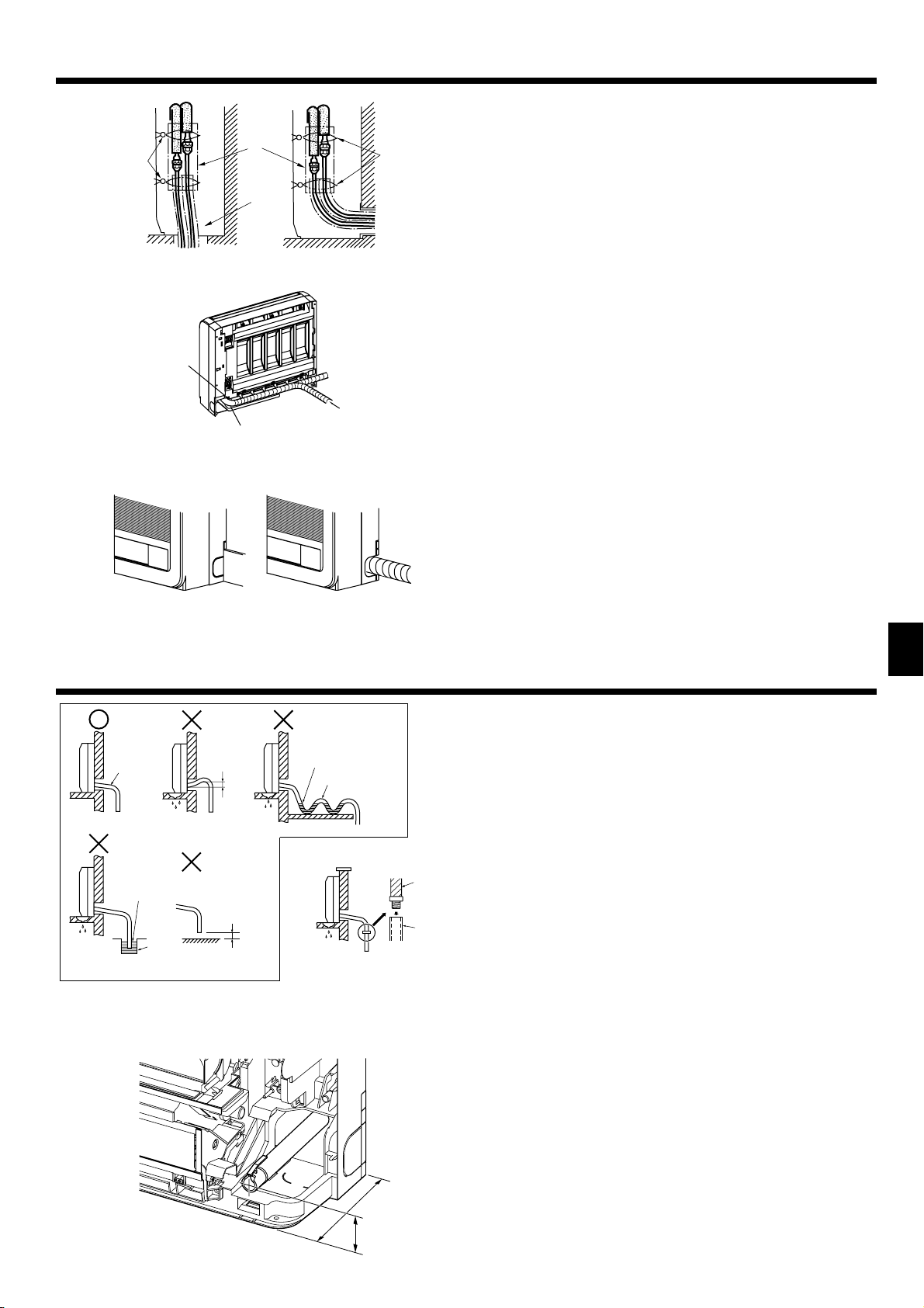
4. Tuyau de réfrigérant
Fig. 4-3
3)
Pose d’un dispositif de vidange
Installing flushagainst a wall with
contre un mur avec plinthe
molding
2)1)
Fig. 4-4
Fig. 4-5
Pour la tuyauterie côté gauche ou
For left or right piping
côté droit
1) Pour la tuyauterie inclinée vers le bas cote droit (Fig. 4-3)
2) Pour la tuyauterie autre que celle inclinée vers le bas cote droit (Fig. 4-4)
Colliers
A
Gaine de tuyau
B
Retirez le couvercle.
C
• Veillez à isoler les tuyaux de connexion et placez-les près de l’arrière de l’appareil
intérieur pour éviter qu’ils entrent en contact avec le panneau frontal.
• Veillez à ne pas écraser les tuyaux de connexion en les pliant.
3) Pour la tuyauterie cote gauche ou arrière gauche (Fig. 4-5)
Attachez les tuyaux de connexion et le fl exible de vidange ensemble, puis entou-
rez-les d’une bande de feutre.
Veillez à ce que le fl exible de vidange ne soit pas acheminé vers le haut.
A
Bande de feutre
B
Enroulez la bande de feutre fermement autour des tuyaux et du fl exible en
*
commençant à partir de l’appareil intérieur. (La largeur de chevauchement de
la bande de feutre ne doit pas dépasser 1/2 de la largeur totale de la bande.)
C Commencez par enrouler le ruban adhésif de tuyauterie autour des tuyaux et
du fl exible à 10 mm à l’intérieur de l’appareil intérieur.
Fixez l’extrémité de la bande de feutre à l’aide d’une agrafe de bande.
D
Coupez et utilisez les panneaux latéraux inférieurs sur les côtés gauche et droit de l’
appareil intérieur comme indiqué ci-dessous.
Limez les bords coupés des panneaux latéraux pour éviter qu’ils endommagent le
revêtement isolant. (Fig. 4-6)
Coupez les panneaux latéraux inférieurs pour qu’ils correspondent à la hau-
E
teur de la plinthe.
Fig. 4-6
5. Mise en place du tuyau d’écoulement
Fig. 5-1
Fig. 5-2
5.1. Mise en place du tuyau d’écoulement
• Veillez à incliner la tuyauterie de vidange vers le bas de 1% ou davantage afi n que l’
eau de vidange s’écoule aisément.
• Evitez d’acheminer la tuyauterie de vidange comme illustré sur les exemples mar-
qués d’un “X” sur la Fig. 5-1.
• Si le fl exible de vidange est trop court, consultez la Fig. 5-2 pour le rallonger.
• Si l’appareil intérieur est installé en hauteur comme dans une tour d’habitation,
des vents violents pourraient repousser l’eau de vidange dans le fl exible de vi-
dange et provoquer une fuite d’eau de l’appareil. Le cas échéant, veuillez contacter votre revendeur Mitsubishi Electric le plus proche pour savoir quels accessoires acheter pour éviter ce problème.
• Si le fl exible de vidange est acheminé à l’intérieur de la pièce, veillez à l’enrouler
dans une gaine de protection achetée dans le commerce.
Ne raccordez pas la tuyauterie de vidange directement à une fosse septique, cuve
•
des eaux usées, etc., où du gaz ammoniac ou du sulfure d’hydrogène sont produits.
• En cas de jeu du fl exible de vidange ou si le fl exible remonte à certains endroits,
l’eau de vidange peut ne pas s’écouler aisément et s’accumuler dans le fl exible.
Cette situation peut provoquer l’émission d’un bruit étrange (murmure) par vents
violents ou lorsqu’un ventilateur, etc., est utilisé dans une habitation bien isolée.
Le cas échéant, veuillez contacter votre revendeur Mitsubishi Electric le plus proche pour savoir quels accessoires acheter pour éviter ce problème.
Inclinaison vers le bas
A
Pas d’inclinaison vers le haut
B
Eau de vidange accumulée
C
Air
D
L’extrémité du fl exible de vidange est immergé dans l’eau.
E
Canal de vidange
F
50 mm au plus du sol
G
Tuyau de vidange
H
Flexible en PVC à fi xer (diamètre intérieur: 15 mm) ou tuyau en PVC rigide (VP-15)
I
• Lors de l’acheminement de la tuyauterie de vidange, veillez à acheminer le fl exi-
ble de vidange comme indiqué. (Fig. 5-3)
F
Fig. 5-3
200
50
21
Page 22
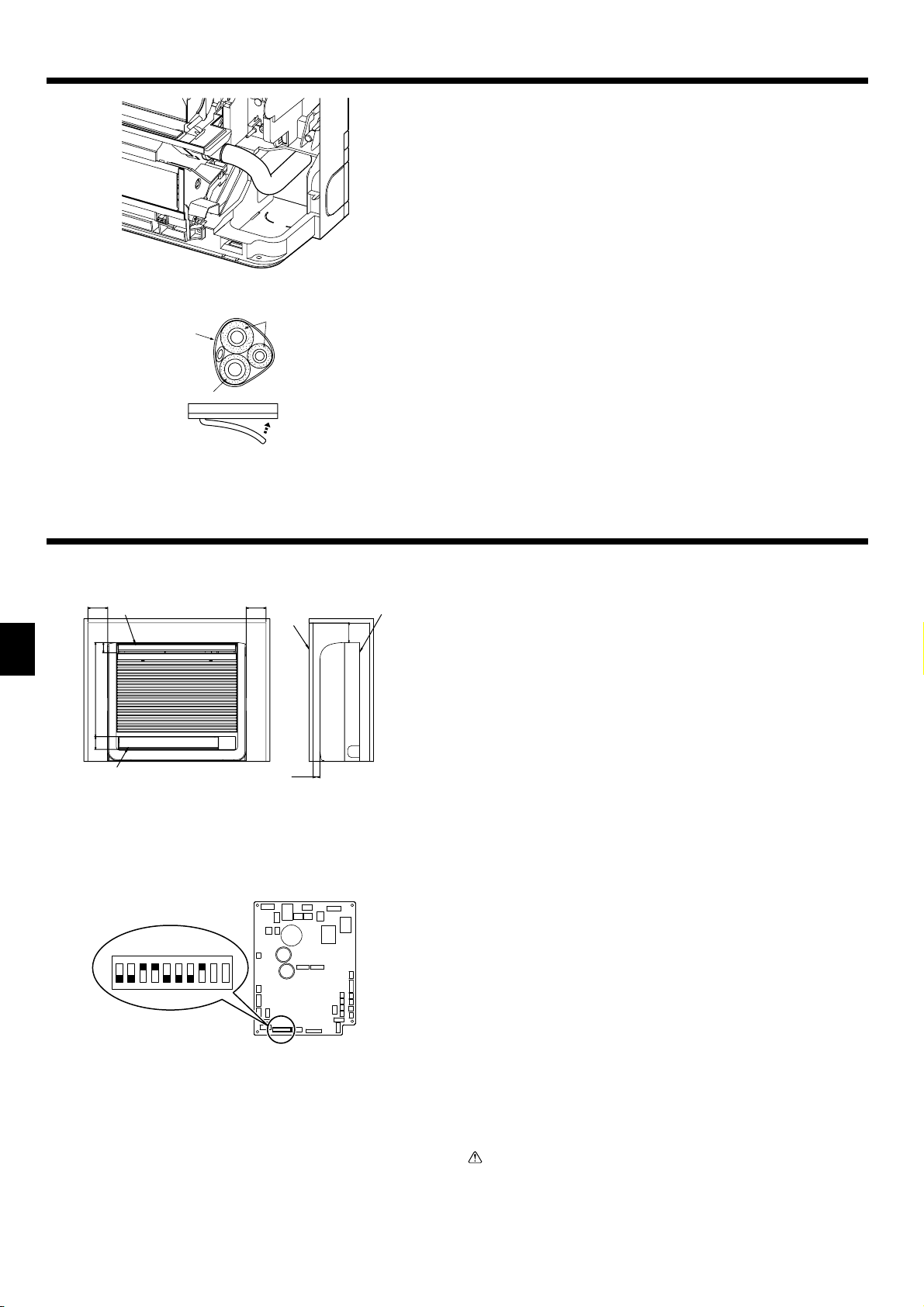
5. Mise en place du tuyau d’écoulement
• Insérez complètement le fl exible de vidange au fond du bac de vidange. (Fig. 5-4)
Veillez à ce que le fl exible de vidange soit bien fi xé dans l’extension du trou du
bac de vidange.
Fig. 5-4
Fig. 5-5
6. Encastrement de l’appareil intérieur dans un mur
F
52
475
65
Fig. 6-1
•
Acheminez le fl exible de vidange en diagonale sous les tuyaux de connexion. (Fig. 5-5)
A Ruban adhésif de tuyauterie
Tuyauterie de réfrigérant
B
Flexible de vidange
C
• Veillez à ce que le fl exible de vidange ne soit pas acheminé vers le haut et que le
tuyau n’ondule pas.
• Ne tirez pas le fl exible de vidange, puis enroulez du ruban autour.
• Acheminez la tuyauterie de sorte qu’elle ne dépasse pas de l’arrière de l’appareil
intérieur. (Consultez le schéma de gauche.)
Tuyauterie dirigée vers l’extérieur
D
Poussez
E
6.1. Encastrement de l’appareil intérieur dans un mur
(Fig. 6-1)
• Les espaces réservés à l’entretien se trouvent du côté droit et du côté gauche (100 mm
minimum) de l’appareil intérieur.
• Un trou est prévu pour le capteur de température sur le côté droit de l’appareil
intérieur; veillez à ne pas obturer les trous existants.
•
Lors de l’installation d’une grille, utilisez une grille munie de barres horizontales inférieures et supérieures étroites afi n que le fl ux d’air en provenance des sorties d’air
inférieure et supérieure n’entre pas en contact avec les barres. Si les barres horizontales bloquent la sortie d’air inférieure, utilisez un socle, etc., pour ajuster la hauteur
de l’appareil intérieur. Si la sortie d’air supérieure ou inférieure est bloquée, le climatiseur ne sera pas en mesure de refroidir ou de réchauffer correctement la pièce.
• Utilisez une grille à barres verticales, etc., qui présente une ouverture de 75%
au minimum. Si la grille est munie de barres horizontales ou si son ouverture est
inférieure à 75%, les performances du climatiseur pourraient être réduites.
• Lorsqu’un appareil intérieur est scellé dans un mur (encastré), le délai nécessaire
à l’élévation de la température de la pièce pour atteindre la température défi nie
augmentera.
100 mm minimum
A
Sortie d’air supérieure
B
Sortie d’air inférieure
C
Grille
D
100 mm minimum
E
Appareil intérieur
F
35 mm minimum
G
22
SW3
ON
1234567 8 9 10
Fig. 6-2
6.2. Confi guration de l’appareil intérieur encastre
(à réaliser) (Fig. 6-2)
• Au moment d’encastrer l’appareil intérieur dans un mur, limitez le mouvement de
l’ailette horizontale de la sortie d’air supérieure de sorte qu’elle ne fonctionne qu’
horizontalement.
• Si cette opération n’est pas effectuée, la chaleur se concentrera sur le mur et la
climatisation de la pièce se fera dans de mauvaises conditions.
• Retirez le couvercle du boîtier électrique et sortez le panneau du contrôleur.
• Placez les commutateurs DIP 3-5 et 3-6 du panneau du contrôleur sur ON (marche).
• Puis, replacez le panneau du contrôleur dans sa position d’origine et posez le
couvercle du boîtier électrique.
Précaution:
Pour éviter que la présence d’électricité statique n’endommage le panneau
du contrôleur, veillez à éliminer l’accumulation d’électricité statique avant
toute manipulation.
Page 23

7. Installations électriques
Bloc de sorties d’alimentation (TB2)
A
Power supply terminal block (TB2)
Bloc de sorties de transmission (TB5)
B
Outdoor unit terminal block (TB5)
Bride pour câbles
C
Wiring clamp
Fig. 7-1
Panneau du contrôleur de l’appareil intérieur
M1M2 CN3A
TB3
TB3
M1M2
M1M2
N
L
TB2 TB5
Fig. 7-2
Indoor controller board
SM1M2 SM1M2
/
SM1M2 SM1M2
TB5 TB5
7.1. Appareil intérieur (Fig. 7-1)
Retirez le couvercle du boîtier électrique.
1
Retirez la vis qui maintient le couvercle du boîtier électrique, puis déposez ce dernier.
•
• Retirez la vis qui maintient l’attache-câble, puis retirez ce dernier.
Raccorder la ligne d’alimentation électrique, la ligne de contrôle de l’appa-
2
reil extérieur, et les lignes de la télécommande.
Suite au raccordement, fi xer les câbles avec le collier de serrage.
► Attacher les fils de la source d’énergie à la boîte de contrôle en utilisant un
manchon butoir pour la force de traction (connexion PG ou équivalent).
• Une intervention technique ou toute autre circonstance peut demander le retrait
du boîtier électrique; aussi, les câbles doivent être suffi samment lâches.
• Des travaux de mise à la terre de Classe 3 doivent être effectués (diamètre du
câble de terre: 1,6 mm minimum)
Lorsque le câblage est terminé, remonter les parties déposées dans l’ordre inverse à celui de leur retrait.
7.2. Câblage de l’alimentation
• Installer une mise à la terre plus longue que les autres câbles.
• Les codes d’électricité pour l’alimentation ne seront pas inférieurs à ceux indi-
qués dans les directives 60245 IEC 53 ou 60227 IEC 53.
• Lors de l’installation du climatiseur, placer un interrupteur avec une séparation d’
au moins 3 mm entre les contacts à chaque pôle.
Section des câbles d’alimentation : supérieure à 1,5 mm². (3 âmes)
Utiliser un disjoncteur fuite à la terre (NV).
Comme coupe-circuit, prévoir un dispositif pour assurer la déconnexion de tous les
conducteurs actifs de phase d’alimentation.
Avertissement:
Le câblage doit être effectué de telle sorte que les lignes électriques ne soient
pas tendues. Sinon, une surchauffe ou un incendie pourraient se produire.
[Fig. 7-2]
Commutateur 16 A
A
Protection contre la surintensité 16 A
S
B
Appareil intérieur
C
7.3. Types de câbles de commandes
1. Mise en place des câbles de transmission
Types de câbles de
transmission
Diamètre des câbles Supérieur à 1,25mm²
21
51BT5BT5BT
2. Câbles de la Commande à distance M-NET
3. Câbles de la Commande à distance MA
Longueur Inférieure à 200m
Types de câbles Câble blindé MVVS
Diamètre des câbles De 0,5 à 1,25 mm²
Longueur
Types de câbles Câble gainé à 2 âmes (non blindé)
Diamètre des câbles De 0,3 à 1,25 mm²
Longueur Inférieure à 200m
Câble blindé CVVS ou CPEVS
Ajouter toute partie supérieure à 10 m à la longueur maximum permise de 200 m du câble de
transmission.
Le courant total de fonctionnement
D
doit être inférieur à 16 A
Boîte de tirage
E
F
Fig. 7-3
7.4. Raccordement des câbles de la commande à dis-
tance et des câbles de transmission intérieurs et
extérieurs (Fig. 7-3)
• Raccorder l’unité intérieure TB5 et l’unité intérieure TB3. (2 fi ls non polarisés) Le “S”
sur l’unité intérieure TB5 est une connexion pour câbles blindé. Pour les spécifi -
cations techniques des câbles de connexion, se reporter au manuel d’installation
de l’appareil extérieur.
• Installer une commande à distance conformément aux instructions du manuel
fourni avec la commande à distance.
•
Raccorder le câble de transmission de la commande à distance à l’aide d’un câble de
2
0,75 mm
de diamètre d’une longueur de 10 m maximum. Si la longueur nécessaire
est supérieure à 10 m, utiliser un câble de raccordement de 1,25 mm
Commande à distance MA
1
• Connectez le connecteur de la commande à distance MA. (2 fi ls non polarisés)
• CC de 9 à 13 V entre 1 et 2 (Commande à distance MA)
Câble de la commande à distance MA (ACCESSOIRE 9)
a
Commande à distance M-NET
2
• Connecter les points “M1” et “M2” de la borne TB5 de l’appareil intérieur à une
commande à distance M-NET. (2 fi ls non polarisés)
• CC de 24 à 30 V entre M1 et M2 (Commande à distance M-NET)
Bloc terminal pour le câble de transmission intérieur
A
Bloc terminal pour le câble de transmission extérieur
B
Commande à distance
C
2
de diamètre.
23
Page 24

7. Installations électriques
ON
OFF
SW5
220V 240V
SW1
12345678910
SW12
9
8
7
(10ths DIGIT)
SW11
0
1
9
2
8
3
7
4
6
6
5
(1s DIGIT)
CN43
CN82
SW14
SWC
0
1
2
3
4
5
0
1
F
2
3
E
4
D
5
C
6
B
7
A
8
9
./
(BRANCH No.)
.
7.5. Confi guration des adresses (Fig. 7-4)
(Toujours effectuer ces opérations lorsque le système est hors tension.)
• Il existe deux types de réglages de commutateurs rotatifs disponibles, pour le
réglage des adresses de 1 à 9 et au-dessus de 10 et pour le réglage du nombre
de ramifi cations.
Comment défi nir les adresses
1
Exemple: Si l’adresse est “3”, laisser le SW12 (pour les unités supérieures à 10)
sur “0” et faire correspondre le SW11 (pour 1 – 9) avec “3”.
Comment défi nir les numéros des ramifi cations SW14 (série R2 seulement)
2
Le numéro de la branche assignée à chaque appareil intérieur correspond au
numéro de l’ouverture du boîtier de commandes BC sur lequel l’appareil intérieur est raccordé.
Le laisser sur “0” sur les appareils appartenant aux séries autres que R2.
• Les boutons rotatifs sont tous mis sur “0” à la sortie d’usine. Ils servent à défi nir
les adresses des appareils et les numéros de branches comme souhaité.
Fig. 7-4
• La détermination de l’adresse des unités intérieures varie en fonction du système
sur site. Procédez au réglage conformément au manuel de référence.
Remarque:
Veuillez régler l’interrupteur SW5 selon la tension de l’alimentation.
•
Réglez l’interrupteur SW5 sur 240 V lorsque l’alimentation est de 230 et 240 volts.
• Lorsque l’alimentation est de 220 volts, réglez SW5 sur 220 V.
Tableau d’adresses
A
7.6. Détection de la température ambiante à l’aide du cap-
teur intégré de la commande à distance (Fig. 7-4)
Si vous voulez détecter la température ambiante à l’aide du capteur intégré de la
commande à distance, mettre le switch SW1-1 du tableau de commandes sur “ON”.
Le réglage indispensable de SW1-7 et SW1-8 permet d’ajuster le fl ux d’air lorsque
le thermomètre est ETEINT.
8. Marche d’essai
8.1. Avant la marche d’essai
F
Lorsque l’installation, le tuyautage et le câblage des appareils intérieur
et extérieur sont terminés, vérifier l’absence de fuites de réfrigérant, la
fi xation des câbles d’alimentation et de commande, l’absence d’erreur de
polarité et contrôler qu’aucune phase de l’alimentation n’est déconnectée.
Utiliser un mégohm-mètre de 500V pour s’assurer que la résistance entre
les terminaux d’alimentation électrique et la terre soit au moins de 1,0 M .
Touche ON/OFF
A
TEST RUN
COOL, HEAT
˚C
TEMP.
MENU
MONITOR/SET
BACK DAY
PAR-21MAA
CLOCK
Fig. 8-1
ON/OFF
˚C
OPERATION
SIMPLE
ON/OFF
CHECK
CLEAR
FILTER
TEST
ON/OFF button
Affi chage de la marche d’essai
B
Test run display
Affichage de la température
C
Indoor liquid pipe
intérieure de la conduite de
temperature display
liquide
ON/OFF lamp
Témoin ON/OFF
D
Power display
Affi chage de mise sous tension
E
Error code display
Affi chage du code d’erreur
F
Test run remaining time
Affi chage du temps restant pour la
display
marche d’essai
Set temperature button
Touche de réglage de la tempé-
G
Mode selection button
rature
Fan speed button
Touche de sélection des modes
H
Air direction button
Touche de réglage de la vitesse
I
TEST button
de ventilation
Touche de la direction de l’air
J
Touche TEST
M
Remarque:
• Si un code d’erreur s’affi che sur la télécommande ou si le climatiseur ne fonctionne pas correctement, consulter le manuel d’installation de l’appareil exté-
rieur ou tout autre manuel technique.
• La minuterie d’arrêt (OFF) est programmée pour arrêter automatiquement l’essai de fonctionnement au bout de 2 heures.
• Pendant l’essai de fonctionnement, le temps restant apparaît sur l’affi chage du temps.
• Pendant l’essai de fonctionnement, la température des tuyaux de réfrigérant de l’appareil intérieur apparaît sur l’affi chage de température de la pièce de la
télécommande.
• Lorsqu’on appuie sur la touche VANE ou LOUVER, le message “NOT AVAILABLE” (indisponible) peut apparaître sur l’affi chage de la télécommande selon le
modèle de l’appareil intérieur ; il ne s’agit en aucun cas d’un dysfonctionnement.
• Sur les appareils de la série PFFY-P·VKM, la direction du débit d’air affi chée sur la télécommande est différente de ce qu’elle est en réalité. Veuillez consulter
le tableau suivant.
Ne pas effectuer ce test sur les terminaux des câbles de contrôle (circuit à
basse tension).
Avertissement:
Ne pas utiliser le climatiseur si la résistance de l’isolation est inférieure à 1,0
M.
8.2. Marche d’essai
Utilisation de la télécommande fi laire (Fig. 7-1)
Mettre l’appareil sous tension au moins douze heures avant l’essai de fonction-
1
nement.
Appuyer deux fois sur la touche [TEST] (ESSAI).
2
des “TEST RUN” (ESSAI DE FONCTIONNEMENT)
Appuyer sur la touche [Mode selection] (Sélection Mode) et passer en mode
3
refroidissement (ou chauffage). Vérifi er si la souffl erie souffl e de l’air froid (ou
chaud).
Appuyer sur la touche [Fan speed] (Vitesse souffl erie).
4
de la souffl erie change.
Appuyer sur [la touche de direction de l’air] ou sur [la grille d’admission]. Vé-
5
rifi er le fonctionnement des ailettes ou de la grille.
Vérifi er le bon fonctionnement du ventilateur de l’appareil extérieur.
6
Arrêter l’essai de fonctionnement en appuyant sur la touche [ON/OFF] (Marche/
7
Arrêt). Arrêt
Enregistrez un numéro de téléphone.
8
Le numéro de téléphone de l’atelier de réparation, de l’agence commerciale,
etc., à contacter en cas de panne peut être enregistré dans la télécommande.
Le numéro de téléphone s’affi chera en cas d’erreur. Pour prendre connaissance
des procédures d’enregistrement, consultez le mode d’emploi de l’appareil intérieur.
Affi chage à cristaux liqui-
Vérifi er si la vitesse
24
Page 25
8. Marche d’essai
9. Sélection de la sortie d’air
SW5
220V 240V
ON
OFF
12345678910
SW12
0
9
8
7
6
5
(10ths DIGIT)
SW1
SW11
0
1
2
3
4
1
9
2
8
3
7
4
6
5
(1s DIGIT)
SWC
(BRANCH No.)
SWC
CN82
SW14
E
D
C
B
CN43
0
1
F
A
9
Affi chage
Display
En réalité
Actual
123 4
1234
Bascule
gniwS).ziroH(
Bascule
(Horiz.) Swing
• Vous ne pouvez pas régler la direction du débit d’air du registre de sortie d’
air inférieure. Son réglage est effectué de façon automatique par ordinateur.
Grâce à cette fonction, l’air est pulsé simultanément des sorties d’air supérieure
et inférieure de façon à refroidir ou chauffer rapidement la pièce. Vous pouvez
sélectionner cette fonction grâce au commutateur SWC situé sur le panneau de l’
adresse.
2
3
4
5
6
7
8
./
.
Fig. 9-1
SWC
SWC
Remarque :
Note:
L’alimentation principale doit être coupée lorsque vous effectuez ces réglages.
Be sure to operate with the main power turned off.
Description des modes
Description of operation
Mode
Operation
Air pulsé
Air flow
Conditions
Conditions
Upper and lower air flow
Air pulsé vers le haut et vers le bas
La température
Room temperature and
ambiante et la
set temperature are dif-
température défi nie
ferent.
sont différentes.
REFROIDISSEMENT DÉSHUMIDIFICATION CHAUFFAGE
COOL
Air pulsé vers le haut Air pulsé vers le haut
Upper air flow
Température de la pièce
Room temperature is
proche de la température
close toset temperature
défi nie ou capteur
or thermo-off.
thermique inactif.
DRY
Upper air flow only
—
Comment régler l’appareil pour qu’il souffle de l’air depuis les
sorties d’air inférieure et supérieure:
►
Placez le commutateur SWC en position inférieure (“ ”).
(Réglages d’usine)
Les sorties d’air inférieure et supérieure souffl ent automatiquement de l’air tel qu’
illustré dans le tableau ci-dessous.
Comment régler l’appareil pour qu’il souffle de l’air uniquement
depuis la sortie d’air supérieure:
►
Placez le commutateur SWC en position supérieure (“ ”).
VENTILATEUR
NAFTAEH
Air pulsé vers le haut uniquement
Upper and lower air flow
(Conditions normales
(Normal condition (in
(chauffage))
heating))
Air pulsé vers le haut
Upper air flow
Pendant l’opération
During defrosting op-
de dégivrage, début
eration, start of opera-
de l’opération, capteur
tion, thermo-off
thermique inactif
Air pulsé vers le haut et vers le bas
Upper and lower air flow
—
F
Vérifi ez qu’aucun objet ne se trouve dans la zone située autour du clapet d’air de la sortie d’air inférieure.
• Be sure to keep the area around the damper of the lower air outlet free of any objects.
25
Page 26
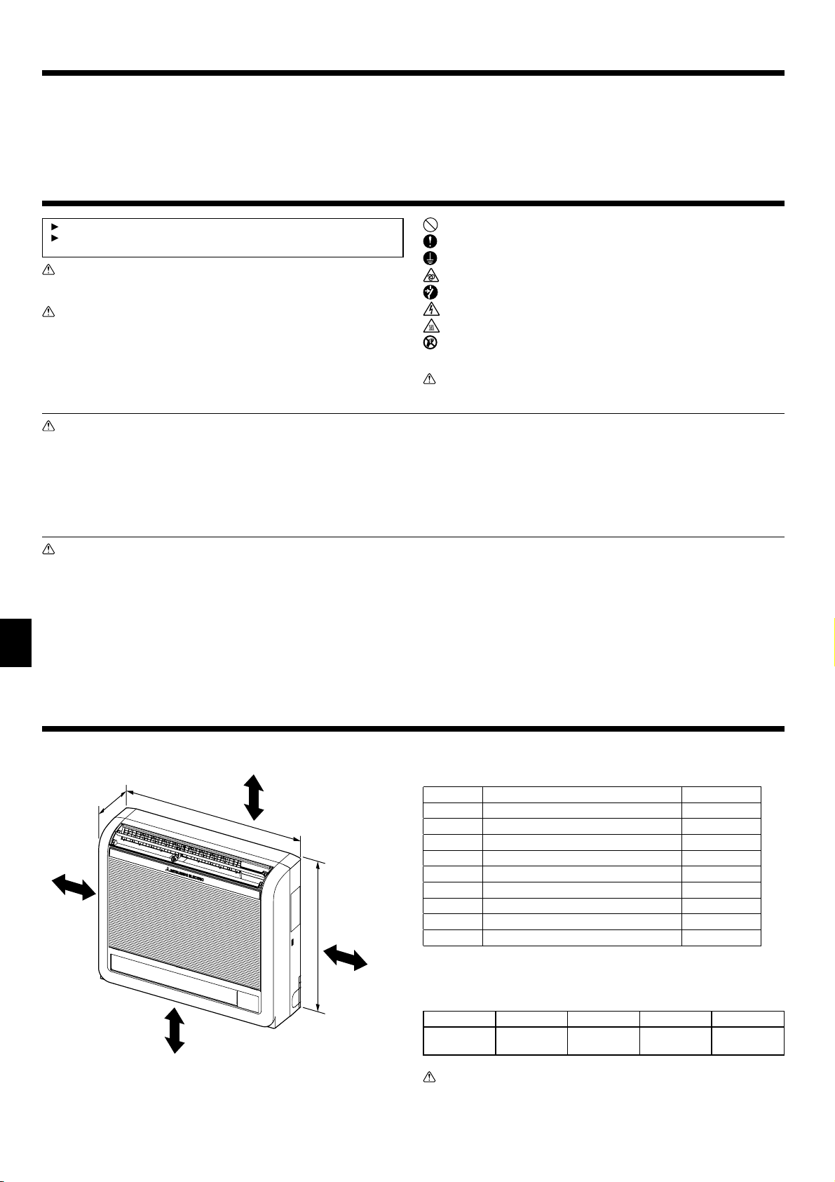
Inhoud
1. Veiligheidsvoorschriften............................................................................... 26
2. Plaats........................................................................................................... 26
3. Het binnenapparaat installeren.................................................................... 27
4. Koelpijp ........................................................................................................ 28
5. Installatie van Draineerbuizen ..................................................................... 29
1. Veiligheidsvoorschriften
Lees alle “Veiligheidsvoorschriften” voordat u het apparaat installeert.
Stel de aanleverende instantie op de hoogte of vraag om toestemming
voordat u dit systeem aansluit op het elektriciteitsnet.
Waarschuwing:
Beschrijft maatregelen die genomen moeten worden om het risico van verwonding of dood van de gebruiker te voorkomen.
Voorzichtig:
Beschrijft maatregelen die genomen moeten worden om schade aan het apparaat te voorkomen.
Informeer de klant na voltooiing van de installatie over de “Veiligheidsvoorschriften”,
het gebruik en het onderhoud van het apparaat en laat het apparaat proefdraaien
om de werking ervan te controleren. Zowel de installatie- als de gebruikershandleiding dienen ter bewaring aan de gebruiker te worden gegeven. Deze handleidingen dienen te worden doorgegeven aan latere gebruikers.
Waarschuwing:
• Vraag de dealer of een erkende installateur om de airconditioner te installe-
ren.
• Installeer het apparaat op een plaats die het gewicht ervan kan dragen.
• Gebruik de gespecifi ceerde verbindingskabels voor de verbindingen.
• Gebruik alleen onderdelen die door Mitsubishi Electric zijn goedgekeurd en
vraag de zaak waar u het apparaat gekocht heeft of een erkend bedrijf om
ze te installeren.
• Raak de vinnen van de warmtewisselaar niet aan.
• Installeer de airconditioner volgens deze installatiehandleiding.
Voorzichtig:
• Als de koelstof die u gebruikt R410A of R407C is, gebruik dan nooit de be-
staande koelleidingen.
• Gebruik esterolie, etherolie of alkalibenzeen (kleine hoeveelheid) als koel-
machineolie voor de coating van soldeerverbindingen en andere koppelingen, als u R410A of R407C-koelstof gebruikt.
• Gebruik de airconditioner niet in een ruimte waar zich voedsel, dieren, plan-
ten, precisie-instrumenten of kunstwerken bevinden.
• Gebruik de airconditioner niet in speciale ruimtes.
NL
• Het apparaat aarden.
• Zorg dat er, zoals vereist, een stroomonderbreker wordt geïnstalleerd.
6. De binnenunit in een wand inbouwen.......................................................... 30
7. Elektrische aansluitingen ............................................................................. 31
8. Proefdraaien ................................................................................................ 32
9. Keuze luchtuitlaten ...................................................................................... 33
: Geeft een handeling aan die u beslist niet moet uitvoeren.
: Geeft aan dat er belangrijke instructies opgevolgd moeten worden.
: Geeft een onderdeel aan dat geaard moet worden.
: Betekent dat u voorzichtig moet zijn met draaiende onderdelen.
: Geeft aan dat het apparaat moet worden uitgezet voor onderhoud.
: Geeft aan dat er een risico van elektrische schokken bestaat.
: Geeft aan dat u op dient te passen voor hete oppervlakken.
: Bij onderhoud dient u de spanning voor zowel het binnenapparaat als het
ELV
buitenapparaat geheel uit te zetten.
Waarschuwing:
Lees de stickers die op het apparaat zitten zorgvuldig.
• Laat het aanleggen van de elektrische leidingen altijd uitvoeren door een
erkend elektricien en zorg dat dit gebeurt volgens de plaatselijk geldende regels.
• Als de airconditioner in een kleine ruimte wordt geïnstalleerd, moeten er
maatregelen worden genomen om te voorkomen dat de concentratie koelstof
in de ruimte hoger is dan de veiligheidsgrens bij eventuele lekkage van koelstof.
• De onderdelen waaruit stukken zijn geponst kunnen verwondingen veroorzaken
door de scherpe randen. Draag bij het installeren beschermende handschoenen.
• Gebruik voor de elektrische aansluitingen kabels met voldoende stroomcapaciteit.
• Gebruik alleen een stroomonderbreker en zekeringen met de gespecifi ceer-
de capaciteit.
• Raak schakelaars nooit met natte vingers aan.
• Raak de koelstofpijpen niet met blote handen aan terwijl de airconditioner
werkt of vlak nadat deze heeft gewerkt.
• Gebruik de airconditioner niet wanneer de panelen en beveiligingen zijn
verwijderd.
• Zet de netspanning niet onmiddellijk na gebruik van het apparaat uit.
2. Plaats
B
200
700
D
Fig. 2-1
(mm)
A
600
C
De volgende accessoires horen bij het binnenapparaat te zijn meegeleverd.
Artikelnummer
1
2
3
4
5
6
7
8
9
Afvoerslang 1
Pijpafdekking 1
Band 2
Montagebeugel voor binnenunit 1
Bevestigingsschroef voor 4 4 × 25 mm 5
Houtschroef voor bevestiging van de binnenunit
Ring van
Vilttape (voor de pijpen links of linksachter) 1
MA-afstandsbedieningskabel 1
Accessoire Hoeveelheid
6
4
4
2.1. Buitenafmetingen (Binnenapparaat) (Fig. 2-1)
De unit dient stevig bevestigd te worden aan een constructie die het gewicht kan
dragen.
Modellen A B C D
P20/25/32/40 100 mm of meer 100 mm of meer 100 mm of meer
Waarschuwing:
Bevestig het binnenapparaat tegen een muur die sterk genoeg is om het gewicht van het apparaat te dragen.
150 mm of minder
vanaf de vloer
26
Page 27
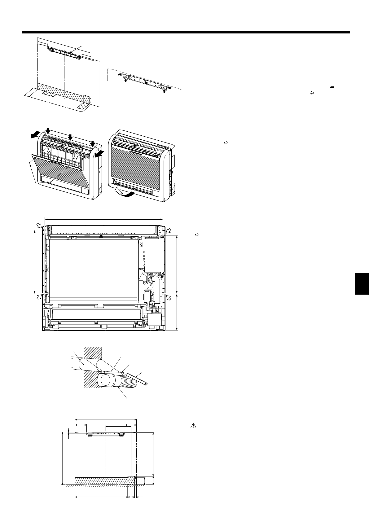
3. Het binnenapparaat installeren
200
131
(700)
Fig. 3-1
Fig. 3-3
131
14
586
(600)
674
Fig. 3-2
Fig. 3-4
(mm)
3.1. Aanbrengen van de montagebeugel voor de binnenunit
• Breng de beugel stevig op de wand aan (met draadeinden en dergelijke). (Fig. 3-1)
• Stel de montagebeugel met een waterpas horizontaal af.
• Monteer de binnenunit op maximaal 150 mm boven de vloer.
Montagebeugel voor de binnenunit
A
Opmerking:
Om mogelijke trillingen van de montagebeugel voor de binnenunit te voorkomen, dient u deze te bevestigen met de gaten zoals aangegeven door .
Maak de beugel indien mogelijk vast bij de gaten volgens . (Fig. 3-2)
3.2. Voorbereiden van de binnenunit
Open het voorste rooster door op de 2 plaatsen te drukken zoals aangegeven
1
door de pijlen . (Fig. 3-3)
Open het voorste rooster en draai de beide schroeven los.
2
Open de horizontale klep van de bovenste luchtuitlaat, druk op drie plaatsen aan
3
de bovenkant van het voorpaneel, en trek de bovenkant van het rooster van de
binnenunit weg.
Schroeven
B
Verwijder het voorste rooster in opwaartse richting. (Fig. 3-4)
4
3.3. Installatie van het binnenapparaat (Fig. 3-5)
• Haak de bovenkant van de binnenunit aan de montagebeugel.
• Maak de binnenunit met de meegeleverde houtschroeven en ringen op 2 plaatsen
( ) elk aan de bovenkant en het midden van de unit vast.
Opmerking:
Bevestig de binnenunit stevig aan de muur, en zorg ervoor dat er geen opening is tussen unit en muur.
363
333210
NL
Fig. 3-5
Fig. 3-6
1)
131
14
600
700
599
288
131
496
97
80
2378
Fig. 3-7
3.4. Gaten boren in de wand en de vloer
3.4.1. Gaten boren (Fig. 3-6)
Boor gaten van ø 65 mm of ø 75 mm die ongeveer 5 tot 7 mm diep zijn en vanuit
1
de kamer naar buiten enigszins afl open.
Breng plug in de gaten aan.
2
Muurgat
A
Diameter 65 mm of 75 mm
B
Binnenkant
C
Muurgat doorsnee
D
Muurdikte
E
Eén schaal
F
Snijd met 1 extra lengte op de meter.
G
Huls voor het muurgat
H
Voorzichtig:
Gebruik altijd de pluggen. Dit om te voorkomen dat de verbindingskabels
tussen de binnen- en buitenunits een metalen voorwerp kunnen raken, of
dat bij spouwmuren de kabels door kleine knaagdieren worden aangevreten,
waardoor een uiterst gevaarlijke situatie zou kunnen ontstaan.
3.4.2. De positie van de gaten bepalen
De gedeeltes waar de pijpen kunnen lopen worden aangegeven door ovale lijnen
in de afbeelding.
1) Pijpen achter of linksachter (Fig. 3-7)
(De volgende afbeelding is een vooraanzicht van de installatieplaats van de binnenunit.)
27
Page 28

3. Het binnenapparaat installeren
2)
3)
4. Koelpijp
NL
60
200
60
19
60
Fig. 3-9
±0,5°
øA
°
90
150
168
45°±2°
R0,4 ~ R0,8
Fig. 4-1
700
Fig. 3-8
4)
75
61
31
62
Fig. 3-10
(mm)
73
105
147
2) Voor pijpen rechts naar beneden of links naar beneden (Fig. 3-8)
(Fig. 3-8)
(In de volgende afbeelding wordt de bodem van de binnenunit van bovenaf weergegeven.)
Als de unit aan de wand wordt aangebracht.
A
Als de unit op de vloer wordt aangebracht.
B
3) Voor pijpen aan de linkerzijde (Fig. 3-9)
4) Voor pijpen aan de rechterzijde (Fig. 3-10)
3.4.3. Afdichten van de gaten
Dicht de gaten met kit of afdichtingsmiddel af.
19 60
60
4.1. Aansluiten van de pijpen (Fig. 4-1)
• Als u koperen pijpen gebruikt, moet u de vloeistof- en gaspijpen met isolatiemateriaal bekleden (hittebestendig tot 100°C, dikte van 12 mm of meer).
• De delen van de afvoerpijp die binnenshuis lopen, moeten worden bekleed met
isolatiemateriaal van polyethyleenschuim (relatieve dichtheid 0,03, dikte 9 mm of
meer).
• Doe een dun laagje koelmachineolie op de leiding en het aansluitingsoppervlak
voordat u de “fl are”-moer vastdraait.
• Draai met gebruik van twee pijptangen de aansluitende leidingen vast.
• Isoleer met meegeleverd isolatiemateriaal voor koelpijpen de aansluitingen aan
de binnenzijde van het apparaat. Voer de isolatie zorgvuldig uit.
Afsnijmaten tromp
A
Buitendiameter koperen pijp
(mm)
ø6,35 8,7 - 9,1
ø9,52 12,8 - 13,2
ø12,7 16,2 - 16,6
ø15,88 19,3 - 19,7
ø19,05 23,6 - 24,0
Afmetingen tromp
øA (mm)
Maten van de koelstofl eidingen en aandraaimoment van de optrompmoeren
B
R407C of R22
Vloeistofpijp Gaspijp
Aanhaal Aanhaal
Afmeting leiding
(mm)
P20/25/32/40
Breng koelolie aan op de aansluitingsoppervlakken.
C
* Breng geen koelolie aan op de schroefoppervlakken. (Hierdoor kunnen de fl ensmoeren eerder losraken.)
Zorg ervoor dat u de fl ensmoeren gebruikt die aan het apparaat zijn bevestigd. (Het gebruik van andere fl ensmoeren kan barsten tot gevolg hebben.)
D
ODø6,35 14 - 18 ODø12,7 49 - 61
moment
(N.m)
Afmeting leiding
(mm)
(N.m)
moment
R410A
Vloeistofpijp Gaspijp
Aanhaal Aanhaal
Afmeting leiding
(mm)
ODø6,35 14 - 18 ODø12,7 49 - 61
moment
(N.m)
Afmeting leiding
(mm)
(N.m)
moment
4.2. De koelstofpijpen aansluiten
4.2.1. Aanbrengen van de verbindingspijpen
Breng de verbindingspijpen zo aan, dat de pijpen enigszins naar voren, achteren,
links en rechts kunnen bewegen. (Fig. 4-2)
28
Fig. 4-2
Buitendiameter
fl ensmoer
Vloeistofpijp
(mm)
17 26
Gaspijp
(mm)
Page 29

4. Koelpijp
Fig. 4-3
3)
Plaats de unit vlak tegen een
Installing flushagainst a wall with
wand met plinten
molding
2)1)
Fig. 4-4
Fig. 4-5
Voor pijpen links of rechts
For left or right piping
1) Voor pijpen recht naar beneden (Fig. 4-3)
2) Voor pijpen die niet recht naar beneden lopen (Fig. 4-4)
Banden
A
Pijpafdekkingen
B
Verwijder de afdekking.
C
• Isoleer de verbindingspijpen en plaats ze bij de achterzijde van de binnenunit,
zodat ze geen contact met het voorpaneel maken.
• Let er bij het buigen op, dat de pijpen niet in elkaar worden gedrukt.
3) Voor pijpen links of linksachter (Fig. 4-5)
Maak een bundel van de verbindingspijpen en de afvoerslang en wikkel ze vervolgens in vilttape.
Let erop dat de afvoerslang niet omhoog mag lopen.
A
Vilttape
B
* Wikkel de vilttape strak rond de pijpen en de slang. Begin vanaf het punt
waar de pijpen en de slang de binnenunit verlaten. (De breedte van de
overlapping van de vilttape mag niet meer dan 1/2 van de breedte van de
tape bedragen.)
Begin met het omwikkelen met tape op 10 mm binnen de binnenunit.
C
Maak het uiteinde van de vilttape met een bandstop vast.
D
Maak aan de linker- en rechterzijde van de binnenunit een inkeping in de onderste
zijpanelen, zoals onderstaand weergegeven.
Maak de insnijdingen in de zijpanelen glad, zodat deze de isolatielaag niet zullen
beschadigen. (Fig. 4-6)
Snij de onderste delen van de zijpanelen weg als uitsparingen voor de plinten.
E
Fig. 4-6
5. Installatie van Draineerbuizen
Fig. 5-1
Fig. 5-2
200
5.1. Installatie van Draineerbuizen
• Geef de afvoerpijpen een helling naar beneden van 1% of meer zodat het afvoer-
water gemakkelijk weg kan vloeien.
• Leid de afvoerpijpen niet zoals in de afbeelding (Fig. 5-1) getoond wordt bij de
voorbeelden waar een “X” bij staat. (Fig. 5-1)
• Als de afvoerslang te kort is, verleng deze dan volgens Fig. 5-2.
• Indien de binnenunit op een hoge locatie is geïnstalleerd zoals in een torenfl at,
kan door harde wind het afvoerwater terug door de afvoerslang worden geblazen
en uit de unit gaan lekken. Neem indien nodig contact op met uw dichtstbijzijnde
vertegenwoordiging van Mitsubishi Electric. Zij kunnen optionele onderdelen bieden om dit probleem op te lossen.
• Indien de afvoerslang binnenshuis loopt, voorzie deze dan van in de handel ver-
krijgbare isolatie.
• Sluit de afvoerpijp niet rechtstreeks op een septic tank, riooltank, enz. aan, aan-
gezien hierin ammoniagassen of zwavelwaterstofgas worden geproduceerd.
• Indien er zich een verzakking in de afvoerslang bevindt of als het uiteinde van
de afvoerslang omhoog loopt, kan het afvoerwater niet gemakkelijk weglopen
waardoor er een geringe hoeveelheid afvoerwater in de slang blijft staan. Bij een
sterke wind of bij gebruik van een ventilator of iets dergelijks in een goed afgesloten woning kan dan een vreemd geluid (borrelen) worden waargenomen. Neem
indien nodig contact op met de dichtstbijzijnde vertegenwoordiger van Mitsubishi
Electric, zij kunnen u extra onderdelen bieden om dit probleem op te lossen.
Afl opend
A
Niet oplopend
B
Verzameld afvoerwater
C
Lucht
D
Het einde van de afvoerslang is in water gedompeld.
E
Afvoerkanaal
F
Maximaal 50 mm van de vloer
G
Aftapslang
H
Vast te zetten pvc-slang (binnendiameter 15 mm) of harde pvc-pijp (VP-15)
I
• Bij het aanleggen van de afvoerpijpen dient u afvoerpijp te laten lopen zoals
weergegeven.(Fig. 5-3)
NL
Fig. 5-3
50
29
Page 30

5. Installatie van Draineerbuizen
• Voer de afvoerslang helemaal in tot aan de onderkant van het afvoerreservoir.
(Fig. 5-4)
Let erop dat de afvoerslang stevig klemt in het uitsteeksel in het gat van het af-
voerreservoir.
Fig. 5-4
Fig. 5-5
6. De binnenunit in een wand inbouwen
52
475
NL
65
Fig. 6-1
• Leid de afvoerslang diagonaal onder de verbindingspijpen door. (Fig. 5-5)
Tape voor de pijpen
A
Koelpijpen
B
Afvoerslang
C
• Let erop dat de afvoerslang niet omhoog loopt en dat de slang geen golvingen
vertoont.
• Trek niet aan de afvoerslang, en doe er vervolgens tape omheen.
• Leid de pijpen zo dat deze niet voorbij de achterkant van de binnenunit uitsteken.
(Zie de afbeelding links.)
Pijpen naar buiten gebogen
D
Drukken
E
6.1. De binnenunit in een wand inbouwen (Fig. 6-1)
• Aan linker-, rechter- en bovenzijde van de binnenunit dient ruimte voor onderhoud
te zijn (100 mm of meer).
• Aan de rechterzijde van de binnenunit is een opening voor de kamertemperatuur-
sensor; sluit dit gedeelte echter niet af.
• Breng een rooster aan met smalle bovenste en onderste horizontale randen,
zodat de luchtstroom van de bovenste en onderste uitlaten niet door de randen
wordt tegengehouden. Als de horizontale randen de onderste luchtuitlaat zouden
blokkeren, stelt u de hoogte van de binnenunit met een standaard of iets dergelijks af. Indien de bovenste of onderste luchtuitlaat zouden worden geblokkeerd,
zou de airconditioner de ruimte niet goed kunnen koelen of verwarmen.
• Gebruik een rooster met verticale randen en dergelijke, waarbij minimaal een
open gedeelte van 75% in stand wordt gehouden. Indien het rooster horizontale
randen heeft of als het open gedeelte minder dan 75% bedraagt, zou de effectiviteit van de unit terug kunnen lopen.
• Indien de binnenunit in een wand is ingebouwd, zal de tijd nodig om de ingestelde
temperatuur van de ruimte te bereiken, groter worden.
100 mm of meer
A
Bovenste luchtuitlaat
B
Onderste luchtuitlaat
C
Rooster
D
100 mm of meer
E
Binnenunit
F
35 mm of meer
G
30
SW3
ON
1234567 8 9 10
Fig. 6-2
6.2.
Instelling van de ingebouwde binnenunit (moet
worden uitgevoerd)
• Bij het inbouwen van de binnenunit in een wand, dient de beweging van de hori-
zontale klep voor de bovenste luchtuitlaat zodanig te worden beperkt, dat deze
alleen nog horizontaal werkt.
• Indien deze instelling niet wordt uitgevoerd, zal er zich in de wand warmte ontwik-
kelen en zal de ruimte niet op correcte wijze worden gekoeld of verwarmd.
• Verwijder de afdekking voor elektrische delen en neem de besturingsplaat uit.
• Zet DIP-schakelaars 3-5 en 3-6 van de besturingsplaat op ON (aan).
• Zet na het instellen van de schakelaars de besturingsplaat terug op zijn plaats en
breng de afdekking voor elektrische delen weer aan.
Voorzichtig:
Voorkom dat statische elektriciteit de besturingsplaat beschadigt, door de
plaat statisch te ontladen voordat u hem aanpakt.
(Fig. 6-2)
Page 31

7. Elektrische aansluitingen
Aansluitblok netspanning (TB2)
A
Power supply terminal block (TB2)
Aansluitblok transmissie (TB5)
B
Outdoor unit terminal block (TB5)
Bedradingsklem
C
Wiring clamp
Fig. 7-1
M1M2
N
L
TB2 TB5
S
7.1. Binnenapparaat (Fig. 7-1)
Verwijder de afdekking voor elektrische delen.
1
• Verwijder een schroef terwijl u de afdekking vasthoudt, en verplaats daarna de
afdekking.
• Verwijder een schroef terwijl u de kabelklem vasthoudt, en verplaats daarna de klem.
Sluit de kabels voor voeding, besturing van de buiteneenheid en afstands-
2
bediening aan.
Borg de kabels na aansluiten met kabelband.
► Maak de stroomkabel aan het regelkastje vast met gebruik van een buffer-
bus om meer trekkracht te krijgen (PG aansluiting of iets dergelijks).
• Aangezien het kastje met elektrische aansluitingen soms verwijderd moet worden
voor onderhoud of om andere redenen, moeten de snoeren voldoende speling
hebben.
• Klasse 3 massa moet worden geleid (massakabel diameter: 1,6 mm of meer)
Nadat de bedrading is aangelegd, brengt u de losgemaakte delen in omgekeerde
volgorde weer aan.
7.2. Voedingsbedrading
• Installeer een aardverbinding die langer is dan andere kabels.
• Voedingscodes van apparaat mogen niet lager zijn dan ontwerp 60245 IEC 53 of
60227 IEC 53.
• Met de airconditioner wordt een schakelaar met ten minste 3 mm contactschei-
ding tussen de polen meegeleverd.
Voedingskabeldiameter: meer dan 1,5 mm
Gebruik een aardlekschakelaar (NV).
Voor de netscheider zal worden voorzien in een middel om te zorgen voor de disconnectie van alle actieve faseaansluitingen van het apparaat.
Waarschuwing:
De bedrading moet zo zijn aangebracht dat de netsnoeren niet gespannen
staan, dit om oververhitting of brand te voorkomen.
[Fig.7-2]
Schakelaar 16 A
A
Overstroombescherming 16 AE Trekdoos
B
Binnenapparaat
C
2
. (3-Aderige)
Totale werkingstroom moet minder zijn dan 16 A
D
Fig. 7-2
Besturing binnenunit
M1M2 CN3A
TB3
Indoor controller board
SM1M2 SM1M2
21
51BT5BT5BT
/
SM1M2 SM1 M2
TB5 TB5
TB3
M1M2
Fig. 7-3
7.3. Types of control cables
1. Bedrading van transmissiekabels
Types transmissiekabel Gepantserde CVVS of CPEVS kabel
Kabeldiameter Minimaal 1,25mm²
Lengte Maximaal 200m
2. M-NET-afstandsbedieningskabels
Kabeltypes Gepantserde MVVS kabel
Kabeldiameter Meer dan 0,5 tot 1,25 mm²
Lengte Voeg een gedeelte van meer dan 10 m bij tot bin-
3. MA-afstandsbedieningskabels
Kabeltypes 2-Aderige mantelkabel (niet afgeschermd)
Kabeldiameter Meer dan 0,3 tot 1,25 mm²
Lengte Maximaal 200m
7.4.
De afstandsbediening en de transmissiekabels voor
nen de langst toegestane transmissiekabellengte
van 200 m.
het binnen- en buitenapparaat aansluiten (Fig. 7-3)
• Sluit binnenapparaat TB5 en buitenapparaat TB3 aan. (Apolair 2-draads) De “S”
op binnenapparaat TB5 is een gepantserde kabelaansluiting. Zie voor specifi ca-
ties van de aansluitkabels de installatie-instructies van het buitenapparaat.
• Monteer een afstandsbediening in overeenstemming met de aanwijzingen die bij
de afstandsbediening zitten.
• Sluit de transmissiekabel van de afstandsbediening aan binnen 10 meter met
gebruik van een kabel van 0,75 mm² ader. Als de afstand meer dan 10 meter is,
gebruik dan een 1,25 mm² aansluitkabel.
MA-afstandbediening
1
• Sluit de aansluiting van de MA-afstandsbediening aan. (Apolair 2-draads)
• DC 9 tot 13 V tussen 1 en 2 (MA-afstandbediening)
MA-afstandsbedieningskabel (Accessoire 9)
a
M-NET-afstandbediening
2
• Sluit de “M1” en “M2” op binnenapparaat TB5 aan op een M-NET-afstandbedie-
ning. (Apolair 2-draads)
• DC 24 tot 30 V tussen M1 en M2 (M-NET-afstandbediening)
Klemmenblok voor transmissiekabel binnenapparaat
A
Klemmenblok voor transmissiekabel buitenapparaat
B
Afstandsbediening
C
NL
31
Page 32

7. Elektrische aansluitingen
220V 240V
ON
OFF
12345678910
SW12
0
9
8
7
6
(10ths DIGIT)
8. Proefdraaien
SW5
1
2
4
5
SW1
3
SW11
0
1
9
2
8
3
7
4
6
5
(1s DIGIT)
Fig. 7-4
SWC
(BRANCH No.)
CN82
SW14
E
D
C
CN43
F
B
A
7.5. De aansluitadressen instellen (Fig. 7-4)
(Zorg ervoor dat er geen stroom op het apparaat staat als u de adressen instelt.)
•
Er zijn twee types draaibare schakelinstellingen beschikbaar: voor het instellen van
adressen 1 tot 9 en groter dan 10, en voor het instellen van aftakkingsnummers.
Hoe u de aansluitadressen instelt
1
Voorbeeld: Als het adres “3” is, laat SW12 (voor groter dan 10) dan op “0” staan
en breng SW11 (voor 1 – 9) in overeenstemming met “3”.
Hoe u de nummers van de aftakkingen instelt bij SW14 (alleen voor de R2-lijn)
2
0
1
2
3
4
5
6
7
8
9
./
.
Het aftakkingsnummer dat aan elk binnenapparaat is toegewezen, is het poortnummer van de BC-bedieningseenheid waarop het binnenapparaat is aangesloten.
Laat de waarde op “0” voor apparaten die niet tot de R2-lijn behoren.
• De draaischakelaars worden in de fabriek allemaal op “0” gezet. Deze schakelaars kunnen worden gebruikt om de adressen van de apparaten en de nummers
van de aftakkingen naar keuze in te stellen.
•
De vaststelling van de aansluitadressen van het binnenapparaat varieert met het systeem dat u gebruikt. Stel ze in overeenstemming met de technische gegevens in.
Opmerking:
Stel de schakelaar SW5 in op het juiste voltage van de netvoeding.
• Wanneer de netspanning 230 of 240 V bedraagt, zet u SW5 op de stand 240 V.
• Wanneer de netspanning 220 V bedraagt, zet u SW5 op de stand 220 V.
Adresbord
A
7.6. De kamertemperatuur oppikken met de ingebouw-
de sensor in een afstandsbediening (Fig.7-4)
Als u de kamertemperatuur wilt oppikken met de ingebouwde sensor in een afstandsbediening, zet dan SW1-1 op het controlebord op “ON” (AAN). U kunt, indien
nodig, de instelling van SW1-7 en SW1-8 ook gebruiken om de luchtstroom aan te
passen als de thermometer van de verwarming op OFF (UIT) staat.
8.1. Voordat u gaat proefdraaien
Controleer nadat u de binnen-en buitenapparaten, inclusief pijpen en
bedrading, volledig heeft geïnstalleerd het geheel op lekken van koelstof,
losse elektrische contacten in voeding of besturingsbedrading en polariteit
en controleer of er geen verbreking van een fase in de voeding is.
Controleer met behulp van een megohmmeter van 500 volt of de weerstand
tussen de netspanningsaansluitpunten en de aarde minimaal 1,0 M
Voer deze test niet uit op de aansluitpunten van de besturingsbedrading
(laagspanningscircuit).
Waarschuwing:
U mag de airconditioner niet gebruiken als de isolatieweerstand minder dan
1,0 M bedraagt.
bedraagt.
Knop ON/OFF
A
NL
TEST RUN
COOL, HEAT
˚C
TEMP.
MENU
MONITOR/SET
BACK DAY
PAR-21MAA
CLOCK
ON/OFF
˚C
OPERATION
SIMPLE
ON/OFF
CHECK
CLEAR
FILTER
TEST
ON/OFF button
Weergave TEST RUN
B
Test run display
(proefdraaien)
Indoor liquid pipe
temperature display
Temperatuurweergave omge-
C
ON/OFF lamp
ving/vloeistofl eiding
Power display
ON/OFF-lampje
D
Error code display
Stroomweergave
E
Test run remaining time
Weergave van foutcode
F
display
Weergave van resterende
Set temperature button
looptijd van test
Mode selection button
Instellingsknop temperatuur
G
Fan speed button
Keuzeknop werkingsmodus
H
Air direction button
Knop ventilatorsnelheid
I
TEST button
Instellingsknop luchtrichting
J
Knop TEST (test)
M
8.2. Proefdraaien (
Schakel het apparaat minimaal 12 uur voor het proefdraaien in.
1
Druk tweemaal op de toets [TEST].
2
Druk op de toets [Mode selection] (Moduskeuze) en schakel over naar de werk-
3
stand koelen (of verwarmen).
Afstandsbediening met draad) (Fig. 8-1)
“TEST RUN” in het LCD-venster
Controleer of er koude (of warme) lucht wordt
uitgeblazen.
Druk op de toets [Fan speed] (Windsnelheid). Controleer of de luchtuit-
4
stroomsnelheid verandert.
Druk op de [instellingsknop luchtrichting] of op de [luifelknop].
5
Controleer de werking van de vin of het luifel.
Controleer de ventilator van het buitenapparaat op een goede werking.
6
Schakel het proefdraaien uit met de [ON/OFF] (AAN/UIT)-toets
7
Leg een telefoonnummer vast.
8
Stop
Het telefoonnummer van de reparatiewerkplaats, het verkoopkantoor, enz., kan
in de afstandsbediening worden vastgelegd, zodat u contact op kunt nemen als
er zich een storing voordoet. Het telefoonnummer wordt dan getoond als er zich
Fig. 8-1
een fout voordoet. Zie voor het registreren de bedieningshandleiding van het
binnenapparaat.
Opmerking:
• Bij verschijnen van een foutcode op de afstandsbediening of als de airco niet goed werkt; zie de gebruiksaanwijzing van de buiteneenheid of andere technische documentatie.
• De OFF timer is zodanig ingesteld dat de proefl oop na 2 uur automatisch stopt.
• Tijdens de proefl oop verschijnt de nog resterende tijd op het tijddisplay.
• Tijdens de proefl oop verschijnt de temperatuur van de koelmiddelleidingen van de binneneenheid op het ruimtetemperatuur-display van de afstandsbedie-
ning.
• Door indrukken van toets VANE of LOUVER kan de melding “NOT AVAILABLE” (niet beschikbaar) verschijnen op het display van de afstandsbediening, afhankelijk van het binneneenheidmodel. Dit is geen storing.
• Voor het type PFFY-P·VKM verschilt de luchtrichting die de afstandsbediening aangeeft van de werkelijke luchtrichting. Zie de volgende tabel.
32
Page 33

8. Proefdraaien
9. Keuze luchtuitlaten
SW5
220V 240V
ON
OFF
SW1
12345678910
SW12
9
8
7
(10ths DIGIT)
SW11
0
6
5
1
2
3
4
0
1
9
2
8
3
7
4
6
5
(1s DIGIT)
SWC
(BRANCH No.)
SWC
CN82
SW14
E
D
C
B
CN43
0
1
F
A
9
Display
Werkelijk
Actual
123 4
1234
(Horiz.) Swing
gniwS).ziroH(
• De luchtrichting voor de demper van de onderste luchtuitlaat is niet in te
stellen. Deze luchtrichting wordt per computer automatisch geregeld.
Met deze functie kunt u de lucht tegelijkertijd uit de bovenste en onderste
luchtuitlaat laten komen zodat de ruimte effectief gekoeld of verwarmd wordt. U
stelt de functie in met de schakelaar SWC op de adressenplaat.
2
3
4
5
6
7
8
./
.
Fig. 9-1
SWC
SWC
Opmerking:
Note:
Let erop dat de netspanning uit staat als u omschakelt.
Be sure to operate with the main power turned off.
Beschrijving van de werking
Description of operation
Bedrijf KOELEN DROGEN VERWARMEN
Operation
Luchtstroom
Air flow
Upper and lower air flow
Bovenste en onderste luchtstroom
De temperatuur van de
Room temperature and
Omstandigheden
Conditions
Zorg ervoor dat het gedeelte rond de instelklep van de onderste luchtuitlaat vrij van voorwerpen is.
• Be sure to keep the area around the damper of the lower air outlet free of any objects.
ruimte en de ingestelde
set temperature are dif-
temperatuur verschillen
ferent.
van elkaar.
COOL
Upper air flow
Bovenste luchtstroom
Kamertemperatuur
Room temperature is
is dicht bij ingestelde
close toset temperature
temperatuur of
or thermo-off.
thermostaat uit.
Alleen bovenste luchtstroom
Upper air flow only
Instelling om de lucht zowel uit de bovenste als de onderste
luchtuitlaten te blazen:
►
Zet schakelaar SWC in de benedenstand (“ ”). (fabrieksinstelling)
De lucht blaast automatisch uit de bovenste en onderste luchtuitlaten, zoals
getoond in de onderstaande tabel.
Instelling om alleen lucht uit de bovenste luchtuitlaat te laten
stromen:
►
Zet schakelaar SWC in de bovenstand (“ ”).
DRY
Upper and lower air flow
Bovenste en onderste luchtstroom
(Normale situatie (bij
—
(Normal condition (in
verwarmen))
heating))
Upper air flow
Bovenste luchtstroom
Tijdens ontdooien,
During defrosting op-
opstarten of
eration, start of opera-
thermostaat uit.
tion, thermo-off
VENTILEREN
NAFTAEH
Bovenste en onderste luchtstroom
Upper and lower air flow
—
NL
33
Page 34

Contenido
1. Medidas de seguridad ................................................................................. 34
2. Lugar en que se instalará ............................................................................ 34
3. Instalación de la unidad interior ................................................................... 35
4. Tubo de refrigerante .................................................................................... 36
5. Tubería de drenaje ...................................................................................... 37
1. Medidas de seguridad
► Antes de instalar la unidad, asegúrese de haber leído el capítulo de
“Medidas de seguridad”.
► Informe al encargado del suministro u obtenga su consentimiento an-
tes de conectar este equipo al sistema de suministro de alimentación.
Atención:
Describe las precauciones que deben tenerse en cuenta para evitar el riesgo
de lesiones o muerte del usuario.
Cuidado:
Describe las precauciones que deben tenerse en cuenta para evitar daños en
la unidad.
Después de terminar la instalación, explique las “Medidas de seguridad”, funcionamiento y mantenimiento de la unidad al cliente según el Manual de instrucciones y
realice una prueba para asegurarse de que funciona correctamente. Entregue una
copia del Manual de instalación y del Manual de instrucciones al usuario. Estos
manuales deben pasar a usuarios posteriores del equipo.
Atención:
• La instalación del aire acondicionado debe correr a cargo del distribuidor o
de un técnico autorizado.
• Instale la unidad en un lugar capaz de soportar su peso.
• Utilice los cables especifi cados para la instalación eléctrica.
• Utilice sólo accesorios autorizados por Mitsubishi Electric y pida a su distri-
buidor o a una empresa autorizada que se los instale.
• No toque las aletas del intercambiador de calor.
• Instale el aire acondicionado según se indica en este manual de instalación.
Cuidado:
No utilice los tubos de refrigerante existentes cuando utilice el refrigerante
•
R410A o R407C.
•
Utilice aceite de éster, aceite o alquilobenceno (en pequeñas cantidades) como
aceite de refrigerador para recubrir las conexiones abocinadas y bridadas al
usar refrigerante R410A o R407C.
•
No utilice el aire acondicionado en lugares en los que se guarde comida, animales domésticos, plantas, instrumentos de precisión u obras de arte.
•
No utilice el equipo de aire acondicionado en entornos especiales.
Conecte la unidad a tierra.
•
Instale un interruptor para el circuito de fugas.
•
6. Empotrado de la unidad interior en una pared ............................................ 38
7. Trabajo eléctrico .......................................................................................... 39
8. Prueba de funcionamiento........................................................................... 40
9. Selección de la salida de aire ...................................................................... 41
: Indica una acción que debe evitarse.
: Indica que deben seguirse unas instrucciones importantes.
: : Indica una pieza que debe estar conectada a tierra.
: Indica que debe tenerse cuidado con las piezas giratorias.
: Indica que debe apagarse el interruptor principal antes de intervenir en la uni-
dad.
: Peligro de descarga eléctrica.
: Peligro por superfi cie caliente.
: A la hora de realizar una reparación, desconecte el interruptor principal tan-
ELV
to de la unidad interior como de la exterior.
Atención:
Lea atentamente las etiquetas adheridas a la unidad principal.
• Todas las conexiones eléctricas deberán ser realizadas por un electricista
autorizado de acuerdo con la normativa local.
• Si el aire acondicionado se instala en una habitación pequeña deberán tomarse medidas para prevenir que la concentración de refrigerante exceda
los límites de seguridad incluso si hubiese fugas.
• Las partes perforadas de caras recortadas pueden causar daños por cortes, etc. Los instaladores deberán llevar equipo de protección adecuado
como por ejemplo guantes, etc.
• Utilice cables de alimentación de capacidad y gama de corriente adecuadas.
• Utilice un interruptor de circuito y un fusible exclusivamente de la capacidad indicada.
• No toque los enchufes con los dedos mojados.
• No toque las tuberías de refrigerante durante el funcionamiento e inmediatamente después de éste.
• No accione el equipo de aire acondicionado cuando se hayan extraído los
paneles y las protecciones.
• No desconecte la corriente inmediatamente después de parar el funcionamiento del equipo.
2. Lugar en que se instalará
E
200
700
B
D
Fig. 2-1
(mm)
A
600
La unidad interior debe ir acompañada de los siguientes accesorios.
NÚMERO ACCESORIO CANTIDAD
Manguera de drenaje 1
1
Recubrimiento del tubo 1
2
Banda 2
3
Soporte de montaje de la unidad interior 1
4
Tornillo de fi jación para 4 4 × 25 mm 5
5
Tirafondo para la fi jación de la unidad interior
6
Arandela para
7
Cinta de fi eltro (para tuberías izquierda o posterior izquierda)
8
Cable del mando a distancia MA 1
9
6
4
4
1
2.1. Dimensiones exteriores (Unidad interior) (Fig. 2-1)
C
La unidad se debe instalar de forma segura sobre una estructura que pueda soportar su peso.
Modelos A B C D
P20/25/32/40 100 mm o más 100 mm o más 100 mm o más
Atención:
Instale la unidad interior en un pared sufi cientemente fuerte para soportar el
peso de la unidad.
150 mm o menos
desde el suelo
34
Page 35

3. Instalación de la unidad interior
200
131
(700)
Fig. 3-1
Fig. 3-3
131
14
586
(600)
674
Fig. 3-2
Fig. 3-4
(mm)
3.1. Instalación del soporte de montaje de la unidad interior
•
Instale el soporte fi rmemente en la estructura de la pared (montante, etc.). (Fig. 3-1)
• Utilice un nivel para colocar el soporte en horizontal.
• Instale la unidad interior a 150 mm o menos del suelo.
Soporte de montaje de la unidad interior
A
Nota:
Para evitar que el soporte de montaje de la unidad interior vibre ligeramente,
asegúrese de apretarlo en los orifi cios señalados con . Además, si es posi-
ble, apriete el soporte en los orifi cios señalados con . (Fig. 3-2)
3.2. Preparación de la unidad interior
Presione en las 2 posiciones indicadas por las fl echas y abra la rejilla frontal.
1
(Fig. 3-3)
Abra la rejilla frontal y retire los dos tornillos.
2
Abra el defl ector horizontal de la salida de aire superior, empuje la parte su-
3
perior del panel frontal en las tres posiciones y tire del extremo superior de la
rejilla para extraerla de la unidad interior.
Tornillos
B
Levante la rejilla exterior y extráigala. (Fig. 3-4)
4
3.3. Instalación de la unidad interior (Fig. 3-5)
• Enganche el extremo superior de la unidad interior en el soporte de montaje de la
unidad interior.
• Utilice los tirafondos y la arandela para apretar la unidad interior en 2 posiciones
( ) una en el extremo superior y otra en la mitad de la unidad.
Nota:
Fije la unidad interior a la pared de forma segura, comprobando que no que-
363
da espacio entre la unidad y la pared.
333210
E
Fig. 3-5
Fig. 3-6
1)
131
14
600
700
599
288
131
496
97
80
2378
Fig. 3-7
3.4. Realización de orifi cios en la pared y el suelo
3.4.1. Realización de orifi cios (Fig. 3-6)
Haga agujeros de ø 65 ó 75 mm con una profundidad de aprox. 5-7 mm y lige-
1
ramente inclinados hacia fuera de la habitación.
Inserte los manguitos para orifi cios de pared en los orifi cios.
2
Orifi cio de la pared
A
65 ó 75 mm diám.
B
Lado interior
C
Sección transversal del orifi cio de la pared
D
Grosor de la pared
E
Una escala
F
Corte con una longitud de escala suplementaria.
G
Manguito del orifi cio de la pared
H
Cuidado:
Asegúrese de utilizar manguitos para orifi cios de pared. De lo contrario, los ca-
bles de conexión de la unidad interior/exterior podrían entrar en contacto con
algún objeto de metal de la pared o, en caso de paredes huecas, algún pequeño
roedor podría dañar los cables, provocando una situación muy peligrosa.
3.4.2. Determinación de las posiciones de los orifi cios
En la fi gura, las áreas donde se pueden pasar las tuberías están marcadas con
líneas oblicuas.
1) Para tuberías posterior o posterior izquierda (Fig. 3-7)
(La siguiente fi gura es una vista frontal de la situación de instalación de la uni-
dad interior.)
35
Page 36

3. Instalación de la unidad interior
2)
60
200
150
168
700
Fig. 3-8
3)
60
19
60
Fig. 3-9
4. Tubo de refrigerante
±0,5°
°
90
øA
45°±2°
R0,4 ~ R0,8
4)
75
61
31
62
Fig. 3-10
(mm)
73
105
147
2) Para tuberías derecha o izquierda hacia abajo (Fig. 3-8)
(La siguiente fi gura es una vista desde arriba de la base de la unidad interior.)
Si la unidad está instalada en pared.
A
Si la unidad está instalada en el suelo.
B
3) Tubería izquierda (Fig. 3-9)
4) Tubería derecha (Fig. 3-10)
3.4.3. Sellado de los orifi cios
Utilice masilla o material de sellado para sellar los orifi cios.
19 60
60
4.1. Tubos de conexión (Fig. 4-1)
• Si se utilizan tubos de cobre convencionales, envuelva los tubos de gas y líquido con
materiales aislantes (resistente al calor hasta 100°C o más, espesor de 12 mm o más).
• Las piezas interiores del tubo de drenaje tienen que estar envueltas en materiales aislantes de espuma de polietileno (gravedad específi ca de 0,03 y espesor de 9 mm o más).
• Aplique una capa delgada de aceite refrigerante a la superfi cie tubo y de la junta
de asiento antes de apretar la tuerca de abocardado.
• Utilice dos llaves de apriete para apretar las conexiones de los tubos.
• Utilice el aislante de tubería de refrigerante suministrado para aislar las conexiones de la unidad interior. Realice los aislamientos con cuidado.
E
Fig. 4-1
Tamaños de la tubería de refrigerante y par de apriete de la tuerca abocardada
B
Tubería de líquido Tubería de gas Tubería de líquido Tubería de gas
Tamaño de la
tubería
(mm)
P20/25/32/40
Aplique aceite refrigerante para máquinas en toda la superfi cie abocinada.
C
* No aplique aceite refrigerante para máquinas en las partes roscadas. (Esto hará que las tuercas abocardadas tiendan más a afl ojarse.)
Asegúrese de utilizar las tuercas abocardadas que vienen colocadas en la unidad principal. (Si se utilizan productos de venta en comercios, podrían partirse.)
D
O.D. ø6,35 (1/4”)
R407C o R22 R410A
Torsión de
apriete
(N·m)
14 - 18
Tamaño de la
tubería
(mm)
O.D. ø12,7 (1/2”)
Torsión de
apriete
(N·m)
49 - 61
Dimensiones del corte abocinado
A
Tubo de cobre O.D.
(mm)
ø6,35 8,7 - 9,1
ø9,52 12,8 - 13,2
ø12,7 16,2 - 16,6
ø15,88 19,3 - 19,7
ø19,05 23,6 - 24,0
Tamaño de la
tubería
(mm)
O.D. ø6,35 (1/4”)
Torsión de
apriete
(N·m)
14 - 18
Dimensiones de abocinado
Tamaño de la
tubería
(mm)
O.D. ø12,7 (1/2”)
dimensiones øA (mm)
Torsión de
apriete
(N·m)
49 - 61 17 26
4.2. Trabajo de instalación de la tubería del refrigerante
4.2.1. Conexión de la instalación de tuberías
Instale los tubos de conexión de modo que el conjunto de tuberías se pueda mover
ligeramente hacia delante, atrás, izquierda y derecha. (Fig. 4-2)
Tuerca de abocardado O.D.
Tubería de
líquido
(mm)
Tubería de
gas
(mm)
36
Fig. 4-2
Page 37

4. Tubo de refrigerante
Fig. 4-3
3)
Instalación pegada a la pared
Installing flushagainst a wall with
con moldura
molding
2)1)
Fig. 4-4
Fig. 4-5
Para tuberías derecha o izquierda
For left or right piping
1) Para tubería derecha hacia abajo (Fig. 4-3)
2) Para tubería que no vaya a la derecha hacia abajo (Fig. 4-4)
Bandas
A
Recubrimientos de tubo
B
Quite la cubierta.
C
• Asegúrese de aislar los tubos de conexión y de colocarlos cerca de la parte trasera de la unidad interior, de modo que no entren en contacto con el panel frontal.
• Tenga cuidado de no partir los tubos de conexión al doblarlos.
3) Para tuberías izquierda o posterior izquierda (Fig. 4-5)
Una los tubos de conexión con la manguera de drenaje y envuélvalos en cinta de
fi eltro.
Asegúrese de que la manguera de drenaje no va hacia arriba.
A
Cinta de fi eltro
B
* Envuelva fuertemente con la cinta de fi eltro los tubos y la manguera comen-
zando cerca del lugar donde salen de la unidad interior. (La cinta de fi eltro
no se debe superponer sobre sí misma más de un 1/2 de su ancho.)
Comience a envolver la cinta de tuberías alrededor de los tubos y la man-
C
guera 10 mm dentro de la unidad interior.
Apriete el extremo de la cinta de fi eltro con un esparadrapo.
D
Corte y uso los paneles inferior a la derecha o izquierda de la unidad interior tal y
como se muestra a continuación.
Suavice los cantos de los paneles laterales de modo que no dañen el revestimiento aislante. (Fig. 4-6)
Corte los paneles inferiores para ajustarse a la altura de la moldura.
E
5. Tubería de drenaje
Fig. 5-1
Fig. 4-6
Fig. 5-2
200
5.1. Tubería de drenaje
• Asegúrese de tender la tubería de drenaje con una pendiente descendente del
1% o más para facilitar el fl ujo.
• No tienda las tuberías de drenaje tal y como se muestra en los ejemplos marca-
dos con una “X” en la fi gura. (Fig. 5-1)
• Si la manguera de drenaje es demasiado corta, consulte la Fig. 5-2 para ver
cómo se debe empalmar.
• Si la unidad interior se instala en un lugar alto, como un apartamento a gran al-
tura, el viento fuerte puede hacer que el agua de drenaje regrese a través de la
manguera de drenaje y caiga en la unidad. En caso necesario, póngase en contacto con su representante de Mitsubishi Electric más cercano para obtener las
piezas opcionales necesarias para evitar este problema.
• Si la manguera de drenaje pasa por una sala, asegúrese de forrarla completa-
mente con un aislante comercial.
• No conecte la tubería de drenaje directamente a un depósito séptico, depósito
de aguas residuales etc., donde se produzcan gases de amoníaco o sulfato de
hidrógeno.
• Si la manguera de drenaje está fl oja o su extremo se eleva, el agua de drenaje
no fl uirá correctamente y una parte podría quedar retenida en la manguera. Esto
podría provocar ruidos extraños (burbujeo) si hay viento fuerte o si se utiliza un
ventilador, etc. en una vivienda bien sellada. En caso necesario, póngase en
contacto con su representante de Mitsubishi Electric más cercano para obtener
las piezas opcionales necesarias para evitar este problema.
Inclinación hacia abajo
A
No la levante.
B
Agua de drenaje acumulada
C
Aire
D
Extremo de la manguera de drenaje sumergido en agua.
E
Canal de drenaje
F
50 mm o menos del suelo
G
Manguera de drenaje
H
Manguera fl exible de PVC (diámetro interno: 15 mm) o tubo rígido de PVC (VP-15)
I
• Al tender la tubería de drenaje, asegúrese de que la manguera de drenaje ise
tiende tal y como se indica a continuación. (Fig. 5-3)
E
Fig. 5-3
50
37
Page 38

5. Tubería de drenaje
•
Inserte la manguera de drenaje a lo largo de la base del depósito de drenaje. (Fig. 5-4)
Asegúrese de que la manguera de drenaje está bien sujeta en la parte saliente
del orifi cio del depósito de drenaje.
Fig. 5-4
Fig. 5-5
6. Empotrado de la unidad interior en una pared
52
475
65
E
Fig. 6-1
• Tienda la manguera de drenaje en diagonal por debajo de los tubos de conexión.
(Fig. 5-5)
Cinta para tubería
A
Tubería de refrigerante
B
Manguera de drenaje
C
• Asegúrese de que la manguera de drenaje no está tendida hacia arriba ni que
presenta ondulaciones.
• No tire de la manguera de drenaje y envuélvala con cinta.
• Tienda la tubería de modo que no pase más allá de la parte trasera de la unidad
interior. (Consulte la fi gura de la izquierda).
Tubería doblada hacia fuera
D
Empuje
E
6.1. Empotrado de la unidad interior en una pared
(Fig. 6-1)
• Deje un espacio de servicio de 100 mm o más a la derecha y a la izquierda de la
unidad interior.
• A la derecha de la unidad interior hay un orifi cio para el sensor de temperatura de
la sala; por favor, no lo obstruya.
• Si va a instalar una rejilla, utilice una con barras horizontales superiores e inferiores estrechas, de modo que el fl ujo de aire de las salidas superior e inferior no
entre en contacto con las barras. Si las barras horizontales bloquean la salida de
aire, utilice un soporte, etc., para ajustar la altura de la unidad interior. Si la salida
de aire superior o inferior queda bloqueada, el aparato de aire acondicionado no
podrá refrigerar o calentar bien la sala.
• Utilice una rejilla con barras verticales, etc. con un área abierta del 75% como
mínimo. Si la rejilla tiene barras horizontales o si el área abierta es de menos del
75%, el rendimiento del aparato podría verse reducido.
• Si la unidad interior se empotra en una pared, el tiempo necesario para que la
temperatura de la habitación alcance la temperatura ajustada aumentará.
100 o más
A
Salida de aire superior
B
Salida de aire inferior
C
Rejilla
D
100 o más
E
Unidad interior
F
35 o más
G
38
SW3
ON
1234567 8 9 10
Fig. 6-2
6.2.
Ajuste de la unidad interior empotrada (se debe
realizar)
• Al empotrar la unidad interior en una pared, limite el movimiento del defl ector ho-
rizontal para la salida de aire superior de modo que sólo funcione en horizontal.
• Si no se lleva a cabo este ajuste, se acumulará calor en la pared y la habitación
no se refrigerará o calentará adecuadamente.
• Retire la cubierta de la caja eléctrica y extraiga el panel de control.
• Ponga los conmutadores DIP 3-5 y 3-6 del panel de control en posición ON.
• Tras ajustar los conmutadores, vuelva a instalar el panel de control en su posición original e instale la cubierta de la caja eléctrica.
Cuidado:
Para evitar daños en el panel de control debidos a la electricidad estática,
asegúrese de descargar este tipo de electricidad antes de manipularlo.
(Fig. 6-2)
Page 39

7. Trabajo eléctrico
Bloque de terminales de la fuente de alimentación (TB2)
A
Power supply terminal block (TB2)
Bloque de terminales de la transmisión (TB5)
B
Outdoor unit terminal block (TB5)
Prensaestopas
C
Wiring clamp
Fig. 7-1
7.1. Unidad interior (Fig. 7-1)
Retire la cubierta eléctrica.
1
• Quite el tornillo que sujeta la cubierta eléctrica y retírela.
• Quite el tornillo que sujeta la abrazadera de cable y retírela.
Conecte la línea de alimentación, la línea de control de la unidad exterior y
2
las líneas del controlador remoto.
Después de realizar la conexión, asegure los cables con la brida de cables.
► Fije el cable de la fuente de alimentación a la caja de control usando un
casquillo separador para mantener la fuerza de tensión (conexión PG o
similar).
• Como la caja eléctrica se tendrá que extraer para el mantenimiento y otras tareas, los cables deben estar fl ojos.
• Se tiene que efectuar una conexión a tierra del tipo 3 (diámetro del cable de
masa:1,6 mm o más)
Una vez acabado el cableado, vuelva a colocar las piezas extraídas en el orden inverso.
7.2. Cableado de alimentación
• Instalar un cable de puesta a tierra más largo que el resto.
• Los códigos correspondientes al suministro de energía de utilización no deben
ser inferiores a los del diseño 60245 IEC 53 o 60227 IEC 53.
• Debe proporcionarse un interruptor de al menos 3 mm de separación de contac-
to en cada polo en la instalación del acondicionador de aire.
Tamaño del cable de alimentación: más de 1,5 mm
2
.
M1M2
N
L
TB2 TB5
S
► Utilice un interruptor de pérdida a tierra (NV).
El disyuntor ha de disponer de los medios necesarios para garantizar la desconexión de todos los conductores de fase activos de la alimentación.
Atención:
La conexiones se tienen que realizar de manera que los cables de alimentación no queden tensos. De lo contrario se puede producir fuego o un sobrecalentamiento.
[Fig. 7-2]
Interruptor 16 A
A
Protección contra sobrecorriente 16 AE Caja de acceso
B
Unidad interior
C
Corriente de servicio total inferior a 16 A
D
Fig. 7-2
Panel de control interior
M1M2 CN3A
TB3
Indoor controller board
SM1M2 SM1M2
21
51BT5BT5BT
/
SM1M2 SM1 M2
TB5 TB5
TB3
M1M2
7.3. Tipos de cables de control
1. Cables de transmisión
Tipos de cables Cable blindado CVVS o CPEVS
Diámetro del cable Más de 1,25 mm²
Longitud Menos de 200 m
2. Cables de mando a distancia M-NET
Tipos de cables Cable blindado MVVS
Diámetro del cable 0,5 a 1,25 mm²
Longitud
3. Cables de mando a distancia MA
Tipos de cables Cable de 2 almas (no blindado)
Diámetro del cable 0.3 a 1.25 mm²
Longitud Menos de 200 m
Cualquier fragmento que sobrepase los 10 m y
hasta los 200 m de longitud máxima permitida
para los cables.
E
7.4. Conexión de los cables de transmisión del mando
a distancia y de las unidades exterior e interior
(Fig. 7-3)
Fig. 7-3
• Conecte TB5 de la unidad interior y TB3 de la unidad exterior (2 cables no polari-
zados). La “S” en TB5 de la unidad interior indica una conexión de cable blindado. Consulte en el manual de instalación de la unidad exterior las especifi cacio-
nes sobre los cables de conexión.
• Instale el mando a distancia siguiendo las indicaciones del manual que se sumi-
nistra con el mismo.
• Si el cable de transmisión del mando a distancia tiene menos de 10 m, use un
cable de conductor interno aislado de 0,75 mm². Si la distancia es superior a los
10 m, use un cable de enlace de 1,25 mm².
Mando a distancia MA
1
• Conecte el conector para el mando a distancia MA (2 cables no polarizados).
• DC 9 a 13 V entre 1 y 2 (Mando a distancia MA)
Cable del mando a distancia MA (ACCESORIO 9)
a
Mando a distancia M-NET
2
• Conecte el “M1” y el “M2” de la unidad interior TB5 a un mando a distancia
M-NET (2 cables no polarizados).
• DC 24 a 30 V entre M1 y M2 (Mando a distancia M-NET)
Bloque de terminales para los cables de transmisión interiores
A
Bloque de terminales para los cables de transmisión exteriores
B
Mando a distancia
C
39
Page 40

7. Trabajo eléctrico
ON
OFF
SW5
220V 240V
SW1
12345678910
SW12
9
8
7
(10ths DIGIT)
SW11
0
1
9
2
8
3
7
4
6
6
5
(1s DIGIT)
CN43
CN82
SW14
SWC
0
1
2
3
4
5
0
1
F
2
3
E
4
D
5
C
6
B
7
A
8
9
./
(BRANCH No.)
.
7.5. Confi guración de las direcciones (Fig. 7-4)
(Asegúrese de trabajar con la corriente desconectada)
• Hay disponibles dos tipos de confi guraciones para los conmutadores giratorios:
uno para la confi guración de las direcciones 1 a 9 y por encima de 10 y otro para
confi gurar los números de los ramales.
Cómo confi gurar las direcciones
1
Ejemplo: Si la Dirección es “3”, deje SW12 (por encima de 10) en “0” y ponga
SW11 (para 1 – 9) en “3”.
Como confi gurar los números de ramal SW14 (Sólo serie R2)
2
El número de ramal asignado a cada unidad interior es el número de conexión
del controlador BC al que está conectada la unidad interior.
En las unidades que no pertenezcan a la serie R2, deje “0”.
• Los conmutadores giratorios salen de fábrica puestos en “0”. Estos conmutado-
res pueden usarse para confi gurar a voluntad las direcciones de la unidad y los
números de cada ramal.
Fig. 7-4
• Las direcciones de las unidades interiores se determinan de forma distinta en la
propia instalación según el sistema. Confi gúrelas según el manual de datos.
Nota:
Sitúe el interruptor SW5 de acuerdo con el voltaje de la red.
• Sitúelo en posición 240 V cuando el voltaje de la red es de 230 V a 240 V.
• Si el voltaje de la red es de 220 V, sitúe el SW5 en posición 220 V.
Tablero de direcciones
A
7.6. Captar la temperatura de la sala con el sensor
incorporado en el mando a distancia (Fig.7-4)
Si desea captar la temperatura de la sala con el sensor incorporado en el mando a
distancia, ponga el conmutador SW-1-1 en “ON”. El ajuste de SW1-7 y SW1-8 (según sea necesario) también permite ajustar el fl ujo de aire cuando el termómetro
de calefacción está desconectado.
8. Prueba de funcionamiento
8.1. Antes de realizar las pruebas
► Después de la instalación de tubos y cables en las unidades interior y exte-
rior, compruebe que no haya escapes de refrigerante, que no se haya afl oja-
do ni la fuente de alimentación ni el cableado de control, que la polaridad no
sea errónea y que no se haya desconectado ninguna fase de la alimentación.
► Utilice un megaohmímetro de 500 V para comprobar que la resistencia en-
tre los bornes de alimentación y la tierra es como mínimo de 1,0 M .
E
Botón ON/OFF
A
TEST RUN
COOL, HEAT
˚C
TEMP.
MENU
MONITOR/SET
BACK DAY
PAR-21MAA
CLOCK
ON/OFF
˚C
OPERATION
SIMPLE
ON/OFF
FILTER
CHECK
TEST
CLEAR
Fig. 8-1
ON/OFF button
Indicación de la prueba de
B
Test run display
funcionamiento
Indoor liquid pipe
Visualización de temperatura
C
temperature display
del tubo de líquido interior
ON/OFF lamp
Luz ON/OFF
D
Power display
Indicación de la potencia
E
Indicación de código de error
F
Error code display
Indicación de tiempo restante
Test run remaining time
de la prueba de funciona-
display
miento
Set temperature button
Botón de selección de tempe-
G
Mode selection button
ratura
Fan speed button
Botón de selección de modo
H
Air direction button
Botón de selección de la velo-
I
TEST button
cidad del ventilador
Botón de dirección del aire
J
Botón de la lama
M
► No efectúe esta prueba en los bornes de los cables de control (circuito de
bajo voltaje).
Atención:
No utilice el aire acondicionado si la resistencia de aislamiento es inferior a
1,0 M .
8.2. Prueba de funcionamiento
Al usar el controlador remoto cableado (Fig. 6-1)
Encienda el aparato por lo menos 12 horas antes de llevar a cabo la prueba de
1
funcionamiento.
Pulse el botón de prueba de funcionamiento [TEST] (PRUEBA) dos veces.
2
Indicador del cristal líquido de prueba en funcionamiento “TEST RUN” (EJECUCIÓNDE PRUEBA)
3 Pulse el botón de selección de modo [Mode selection] (Modo) y cambie al
modo de refrigeración (o calefacción).
caliente).
4 Pulse el botón de velocidad del aire [Fan speed] (Velocidad del aire). Com-
pruebe que cambia la velocidad del aire.
5 Pulse el [botón de dirección del aire] o el [botón de la lama].
Compruebe el funcionamiento de la paleta o lama.
6 Compruebe el funcionamiento del ventilador de la unidad exterior.
7 Desactive la prueba de funcionamiento pulsando el botón de activación/desac-
tivación [ON/OFF] (ACTIVAR/DESACTIVAR).
8 Registre un número de teléfono.
El controlador remoto permite registrar el número de teléfono de la tienda de
electrodomésticos, distribuidor, etc. con quien se deba contactar en caso de
error. El número aparecerá si se produce algún error. Para conocer el procedi-
miento de registro, consulte el manual de instrucciones de la unidad interior.
Compruebe que sale aire frío (o
Parar
Nota:
• Si aparece un código de error en el controlador remoto o si el aire acondicionado no funciona correctamente, consulte el manual de instalación de la unidad
exterior u otra documentación técnica
• El temporizador de apagado está ajustado para que la prueba de funcionamiento se detenga automáticamente pasadas 2 horas.
• Durante la prueba de funcionamiento, el tiempo restante se muestra en la indicación de tiempo.
• Durante la prueba de funcionamiento, se muestra la temperatura de la tubería del refrigerante de la unidad interior en la indicación del controlador remoto de
la temperatura de la sala.
• Cuando están pulsados los botones VANE o LOUVER, el mensaje “NOT AVAILABLE” (no disponible) puede aparecer en la pantalla del controlador remoto
según el modelo de la unidad interna, pero no se trata de un mal funcionamiento.
•
En el caso de la serie PFFY-P·VKM, la dirección del fl ujo de aire que aparece en. el controlador remoto es distinta de la dirección real. Consulte la siguiente tabla.
40
Page 41

8. Prueba de funcionamiento
9. Selección de la salida de aire
SW5
220V 240V
ON
OFF
SW1
12345678910
SW12
0
1
9
2
8
3
7
4
6
5
(10ths DIGIT)
SW11
0
1
9
2
8
3
7
4
6
5
(1s DIGIT)
SWC
CN43
SWC
CN82
SW14
0
1
F
2
3
E
4
D
5
C
6
B
7
A
8
9
./
(BRANCH No.)
Display
Pantalla
Actual
Real
123 4
1234
Oscilación
gniwS).ziroH(
Oscilación
(Horiz.) Swing
• La dirección del fl ujo de aire del regulador de salida inferior no se puede
ajustar.
La dirección del fl ujo de aire se controla automáticamente desde un orde-
nador.
Con esta función, el aire se expulsa simultáneamente por las salidas superior e
inferior, de modo que la sala se pueda refrigerar o calentar de forma efi caz. Esta
función se establece con el conmutador SWC del tablero de direcciones.
.
Fig. 9-1
SWC
SWC
Nota:
Note:
Asegúrese de trabajar con la fuente de alimentación principal desconectada.
Be sure to operate with the main power turned off.
Descripción de funcionamiento
Description of operation
Funcionamiento REFRIGERACIÓN REFRIGERACIÓN CALEFACCIÓN
Operation
Flujo de aire
Air flow
Flujo de aire superior e inferior
Upper and lower air flow
La temperatura de la
Room temperature and
Condiciones
Conditions
sala y la temperatura
set temperature are dif-
ajustada son distin-
ferent.
tas.
COOL
Flujo de aire superior
Upper air flow
La temperatura de la sala
Room temperature is
está cerca de la temperatu-
close toset temperature
ra ajustada o el termostato
or thermo-off.
está desconectado.
Sólo fl ujo de aire superior
Upper air flow only
Para ajustar la expulsión del aire por las salidas superior e inferior:
►
Ponga el conmutador SWC en la posición inferior (“ ”). (Ajuste
de fábrica)
El aire saldrá automáticamente por las salidas superior e inferior tal y como se
muestra en la siguiente tabla.
Para ajustar la expulsión del aire por las salidas superior e inferior:
►
Ponga el conmutador SWC en la posición superior (“ ”).
DRY
Flujo de aire superior e inferior
Upper and lower air flow
(Condición normal
—
(Normal condition (in
(calefacción))
heating))
Flujo de aire superior
Durante el funcionamien-
During defrosting op-
to de desescarchado,
eration, start of opera-
inicio del funcionamiento,
tion, thermo-off
termostato desconectado
Upper air flow
FAN
NAFTAEH
Flujo de aire superior e inferior
Upper and lower air flow
—
E
Asegúrese de que la zona alrededor del regulador de la salida de aire inferior está libre de cualquier objeto.
• Be sure to keep the area around the damper of the lower air outlet free of any objects.
41
Page 42

Indice
1. Misure di sicurezza ...................................................................................... 42
2. Luogo in cui installare .................................................................................. 42
3. Installazione della sezione interna............................................................... 43
4. Tubo del refrigerante ................................................................................... 44
5. Installazione della tubazione di drenaggio................................................... 45
1. Misure di sicurezza
► Leggere attentamente la sezione “Misure di sicurezza” prima di far
funzionare l’unità.
► Prima di collegare l’apparecchiatura alla rete di alimentazione, infor-
mare l’ente energia o richiederne il consenso.
Avvertenza:
Descrive le precauzioni da prendere per evitare il rischio di lesioni, anche
mortali, per l’utente.
Cautela:
Descrive le precauzioni da prendere per evitare il danneggiamento dell’unità.
Terminata l’installazione, spiegare le “Misure di sicurezza”, l’uso e la manutenzione
dell’unità al cliente conformemente alle informazioni riportate nel manuale d’uso
ed eseguire il ciclo di prova per accertare che l’impianto funzioni normalmente.
Consegnare il Manuale d’uso ed il Manuale di installazione al cliente, che li dovrà
conservare e, in futuro, consegnarli ad eventuali nuovi utenti.
Avvertenza:
• Chiedere al distributore o ad una società autorizzata di installare l’unità.
• Installare l’unità in un luogo in grado di sostenere il suo peso.
• Utilizzare solo cavi specifi ci per i cablaggi.
• Utilizzare soltanto accessori autorizzati dalla Mitsubishi Electric e chiedere
al proprio distributore o ad una società autorizzata di installarli.
• Non toccare le alette dello scambiatore di calore.
• Installare l’unità conformemente a quanto indicato nel manuale di installa-
zione.
Cautela:
• Non usare l’esistente tubazione del refrigerante quando si utilizza il refrige-
rante R410A o R407C.
• Usare olio a base di esteri, olio a base di etere o alchilbenzene (in piccola
quantità) per lubrifi care i collegamenti a cartella ed a fl angia, quando si uti-
lizza il refrigerante R410A o R407C.
• Non tenere generi alimentari, animali domestici, piante, strumenti di preci-
sione od opere d’arte nella zona della portata d’aria del condizionatore.
• Non usare il condizionatore in ambienti speciali.
6. Inserimento dell’unità interna in una parete................................................. 46
7. Collegamenti elettrici ................................................................................... 47
8. Prova di funzionamento ............................................................................... 48
9. Selezione dell’uscita aria ............................................................................. 49
: Indica un’azione da evitare.
: Indica la necessità di rispettare un’istruzione importante.
: Indica la necessità di collegare un componente a massa.
: Indica che occorre operare con grande cautela con le parti rotanti.
: Indica che l’interruttore principale deve essere disattivato prima di effettuare
la manutenzione.
: Attenzione alle scosse elettriche.
: Attenzione alle superfi ci roventi.
: Al momento della manutenzione, interrompere l’alimentazione sia della
ELV
sezione interna che esterna.
Avvertenza:
Leggere attentamente le etichette attaccate all’unità principale.
• Tutti i lavori elettrici devono essere eseguiti da un elettricista esperto, nel
rispetto degli standard normativi locali.
• Se il condizionatore d’aria viene installato in una stanza di piccole dimensioni, occorre adottare le misure necessarie per evitare la concentrazione
di refrigerante al di là dei limiti di sicurezza, in caso di perdite.
• Le parti appuntite possono causare ferite da taglio, ecc.. Gli installatori devono pertanto indossare equipaggiamenti protettivi, come guanti, ecc..
• Messa a terra dell’unità.
• Installare un interruttore del circuito, se necessario.
• Utilizzare, per le linee di alimentazione, cavi standard con una capacità suffi ciente.
• Usare soltanto un interruttore del circuito e fusibili della capacità specifi ca-
ta.
• Non toccare alcun interruttore con le dita bagnate.
• Non toccare i tubi del refrigerante con le mani nude durante ed immediatamente dopo il funzionamento.
• Prima di iniziare il funzionamento dell’unità, controllare che tutti i pannelli,
e le protezioni siano installate correttamente.
• Dopo aver arrestato l’unità, non spegnere immediatamente l’interruttore di
alimentazione principale.
2. Luogo in cui installare
I
200
B
D
Fig. 2-1
700
(mm)
A
600
L’unità interna dovrebbe essere in dotazione i seguenti accessori.
N. PARTE ACCESSORIO QUANTITÀ
Tubo di drenaggio 1
1
Copritubo 1
2
Fascetta 2
3
Staffa di fi ssaggio unità interna 1
4
Vite di fi ssaggio per 4 4 × 25 mm 5
5
Vite per legno per il fi ssaggio dell’unità interna 4
6
Rondella di
7
Nastro di feltro (usato per la tubazione a sinistra o in basso a sinistra)
8
Cavo del comando a distanza MA 1
9
6
4
1
2.1. Dimensioni dell’unità (Sezione interna) (Fig. 2-1)
C
L’unità deve essere installata saldamente su una struttura che possa sostenerne il
peso.
Modelli A B C D
P20/25/32/40 Min. 100 mm Min. 100 mm Min. 100 mm
Avvertenza:
Montare la sezione interna su una parete in grado di sopportare perfettamente il peso dell’unità.
A max. 150 mm
dal pavimento
42
Page 43

3. Installazione della sezione interna
200
131
(700)
Fig. 3-1
Fig. 3-3
131
14
586
(600)
674
Fig. 3-2
Fig. 3-4
(mm)
3.1. Installazione della staffa di fi ssaggio dell’unità interna
• Installare la staffa saldamente sulla struttura della parete (pilastro, ecc.). (Fig. 3-1)
• Montare la staffa di fi ssaggio orizzontalmente facendo uso di una livella.
• Installare l’unità interna ad almeno 150 mm dal pavimento.
Staffa di fi ssaggio unità interna
A
Nota:
Per impedire che la staffa di fi ssaggio dell’unità interna vibri lievemente, ac-
certarsi di serrare la staffa sui fori indicati da . Inoltre, se possibile, serrare
la staffa sui fori indicati da . (Fig. 3-2)
3.2. Preparazione dell’unità interna
Premere le 2 posizioni indicate dalle frecce e aprire la griglia anteriore.
1
(Fig. 3-3)
Aprire la griglia anteriore e rimuovere le due viti.
2
Aprire il vano orizzontale per l’uscita aria superiore, premere la parte superiore
3
del pannello anteriore in tre punti e quindi tirare via la parte superiore della griglia dall’unità interna.
Vit
B
Sollevare la griglia anteriore per rimuoverla. (Fig. 3-4)
4
3.3. Installazione dell’apparecchio interno (Fig. 3-5)
• Agganciare la parte superiore dell’unità interna sulla relativa staffa di fi ssaggio.
• Con le viti per legno e la rondella accluse fi ssare l’unità interna su 2 posizioni, ( )
in cima e al centro dell’unità.
Nota:
Fissare saldamente l’unità interna alla parete, facendo sì che non vi sia spazio libero tra l’unità e la parete.
363
333210
I
Fig. 3-5
Fig. 3-6
1)
131
14
600
700
599
288
131
496
97
80
2378
Fig. 3-7
3.4. Esecuzione di fori nella parete e nel pavimento
3.4.1. Esecuzione di fori (Fig. 3-6)
Praticare fori di ø 65 mm o ø 75 mm e circa 5–7 mm di profondità, con leggera
1
angolazione verso il basso e l’esterno dalla stanza.
Inserire le maniche dei fori della parete nei fori.
2
Foro nel muro
A
Diam. di 65 mm o 75 mm
B
Lato interno
C
Sezione foro muro
D
Spessore muro
E
Una misura del righello
F
Tagliare lasciando una lunghezza extra pari alla lunghezza della misura del righello.
G
Manica foro muro
H
Attenzione:
Accertarsi di utilizzare le maniche dei fori della parete. In caso contrario, i fi li
di connessione dell’unità interna/esterna potrebbero venire a contatto con
un oggetto di metallo nella parete o, in caso di pareti vuote, piccoli roditori
potrebbero rosicchiare i fi li, con conseguenze molto pericolose.
3.4.2. Determinazione della posizione del fori
Nella fi gura, le aree in cui la tubazione può essere instradata sono indicate da linee
oblique.
1) Per tubazione posteriore o posteriore sinistra (Fig. 3-7)
(La seguente fi gura è una vista anteriore della posizione d’installazione dell’uni-
tà interna.)
43
Page 44

3. Installazione della sezione interna
2)
60
200
150
168
700
61
75
62
(mm)
31
73
105
147
2) Per tubazione in basso a destra o in basso a sinistra (Fig. 3-8)
(La seguente fi gura è la parte inferiore dell’unità interna vista dall’alto.)
Quando si installa l’unità sulla parete.
A
Quando si installa l’unità sul pavimento.
B
Fig. 3-8
3)
60
19
60
Fig. 3-9
4)
60
Fig. 3-10
19 60
3) Per la tubazione di sinistra (Fig. 3-9)
4) Per la tubazione di destra (Fig. 3-10)
3.4.3. Chiusura a tenuta del fori
Utilizzare stucco o un composto per calafatare per sigillare i fori.
4. Tubo del refrigerante
±0,5°
°
90
øA
45°±2°
R0,4 ~ R0,8
Fig. 4-1
Dimensioni dei tubi del refrigerante e torsione di fi ssaggio del dado svasato
B
I
Tubo del liquido Tubo del gas Tubo del liquido Tubo del gas
Dimensioni
tubo
P20/25/32/40
Applicare olio adatto alle macchine di refrigerazione sull’intera superfi cie di alloggiamento svasata.
C
* Non applicare olio per macchine refrigeranti alle fi lettature. (Questa operazione favorisce l’allentamento dei dadi a cartella)
Utilizzare i dadi a cartella in dotazione con l’unità principale. (L’uso di prodotti disponibili sul mercato può favorire la formazione di crepe)
D
(mm)
O.D. ø6,35 (1/4”)
R407C o R22 R410A
Coppia di
serraggio
(N·m)
14 - 18
Dimensioni
tubo
(mm)
O.D. ø12,7 (1/2”)
Coppia di
serraggio
(N·m)
49 - 61
4.1. Collegamento dei tubi (Fig. 4-1)
•
Se vengono utilizzati dei tubi di rame disponibili in commercio, avvolgere del materiale di isolamento, disponibile in commercio, attorno ai tubi del liquido e del gas
(resistente alla temperatura di 100°C o superiore, spessore di almeno 12 mm).
•
Le parti interne del tubo di drenaggio devono essere ricoperte di materiale di isolamento in schiuma di polietilene (gravità specifi ca di 0,03, spessore di almeno 9 mm).
• Stendere uno strato sottile di olio refrigerante sul tubo e collegare la superfi cie di
appoggio prima di serrare il dado a cartella.
• Serrare i raccordi dei tubi usando due chiavi.
• Isolare i raccordi dell’unità interna utilizzando il materiale isolante fornito per la
tubazione del refrigerante. Effettuare l’operazione di isolamento con cura.
Dimensioni di taglio per raccordo a cartella
A
O.D. del tubo di rame
(mm)
ø6,35 8,7 - 9,1
ø9,52 12,8 - 13,2
ø12,7 16,2 - 16,6
ø15,88 19,3 - 19,7
ø19,05 23,6 - 24,0
Dimensioni
tubo
(mm)
O.D. ø6,35 (1/4”)
Coppia di
serraggio
(N·m)
14 - 18
Dimensioni
tubo
(mm)
O.D. ø12,7 (1/2”)
Dimensioni cartella
dimensioni øA (mm)
O.D. del dado a cartella
Coppia di
serraggio
(N·m)
49 - 61 17 26
Tubo del
liquido
(mm)
Tubo del
gas
(mm)
44
4.2. Realizzazione della tubazione del refrigerante
4.2.1. Installazione del tubo di collegamento
Installare i tubi di collegamento in maniera tale che la tubazione possa spostarsi
leggermente in avanti, indietro, a sinistra e a destra. (Fig. 4-2)
Fig. 4-2
Page 45

4. Tubo del refrigerante
Fig. 4-3
3)
Installazione del fl usso contro una
Installing flushagainst a wall with
parete con modanatura
molding
2)1)
Fig. 4-4
Fig. 4-5
Per la tubazione sinistra e destra
For left or right piping
1) Per la tubazione in basso a destra (Fig. 4-3)
2) Per tubazioni diverse da quella in basso a destra (Fig. 4-4)
Fascette
A
Copritubo
B
Rimuovere il coperchio.
C
• Accertarsi di isolare i tubi di collegamento e porli accanto alla parte posteriore
dell’unità interna, in maniera tale che non vengano a contatto con il pannello anteriore.
• Fare attenzione a non schiacciare i tubi di collegamento quando li si piega.
3) Per la tubazione a sinistra o dietro a sinistra (Fig. 4-5)
Fasciare insieme i tubi di collegamento e il tubo di scarico e quindi avvolgerli in nastro di feltro.
Accertarsi che il tubo di scarico non sia instradato verso l’alto.
A
Nastro di feltro
B
* Avvolgere il nastro di feltro strettamente intorno ai tubi, iniziando vicino al
punto in cui essi sono instradati dall’unità interna. (Lo spazio di sovrapposizione del nastro di feltro non deve essere superiore alla metà della sua
lunghezza).
Iniziare ad avvolgere il nastro della tubazione intorno ai tubi per 10 mm all’
C
interno dell’unità interna.
Serrare l’estremità del nastro in feltro con un fermo per bende.
D
Tagliare e usare i pannelli laterali inferiori sui lati sinistro e destro dell’unità interna
come mostrato di seguito.
Uniformare i bordi tagliati dei pannelli laterali in maniera tale che non danneggino il
rivestimento isolante. (Fig. 4-6)
Tagliare i pannelli laterali inferiori perché corrispondano all’altezza della mo-
E
danatura.
Fig. 4-6
5. Installazione della tubazione di drenaggio
Fig. 5-1
Fig. 5-2
5.1. Installazione della tubazione di drenaggio
• Dare alla tubazione di scarico un’inclinazione verso il basso di almeno 1%, in
modo che l’acqua di scarico fl uisca facilmente.
• Non disporre le tubazioni di drenaggio come illustrato negli esempi contrassegnati
dalla “X” nella fi gura. (Fig. 5-1)
• Se il fl essibile di drenaggio è troppo corto, osservare la Fig. 5-2 per prolungarlo.
Se l’unità interna è installata in una posizione alta, come un appartamento all’ultimo
•
piano, i venti forti possono causare il rifl uire dell’acqua di scarico attraverso il tubo
di scarico e perdite dall’unità. Se necessario, contattare il rappresentante Mitsubishi Electric più vicino per i componenti opzionali atti a prevenire tale problema.
• Se il tubo di scarico è instradato all’interno, accertarsi di avvolgerlo in un isolante
disponibile in commercio.
• Non collegare la tubazione di scarico direttamente a una fossa settica, un serba-
toio per acque di rifi uto, ecc., in cui sia prodotto gas di ammoniaca o solfuro di
idrogeno.
• Se è presente gioco nel tubo di scarico o se l’estremità del tubo di scarico è solle-
vata, l’acqua di scarico potrebbe non rifl uire uniformemente e ne potrebbe rima-
nere parte nel tubo di scarico. Ciò potrebbe causare uno strano rumore (gorgoglio)
in caso di forti venti o quando si usa un ventilatore, ecc., in un ambiente ben chiuso. Se necessario, contattare il rappresentante Mitsubishi Electric più vicino per i
componenti opzionali atti a prevenire tale problema.
Inclinazione verso il basso
A
Nessuna inclinazione verso l’alto
B
Acqua di scarico accumulata
C
Aria
D
L’estremità del tubo di scarico è immersa in acqua.
E
Canale di scarico
F
50 mm o meno da terra
G
Tubo di scarico
H
Flessibile in PVC fi ssabile (diametro interno:15 mm) o tubo in PVC rigido (VP-15)
I
• Quando si instrada la tubazione di scarico, accertarsi che il tubo di scarico sia
instradato come indicato. (Fig. 5-3)
I
Fig. 5-3
200
50
45
Page 46

5. Installazione della tubazione di drenaggio
• Inserire il tubo di scarico completamente sulla base della coppa di scarico. (Fig.
5-4) Accertarsi che il tubo di scarico sia posto saldamente sulla proiezione nel
foro nella coppa di scarico.
Fig. 5-4
Fig. 5-5
6. Inserimento dell’unità interna in una parete
52
475
65
Fig. 6-1
I
• Instradare il tubo di scarico in diagonale sotto i tubi di connessione. (Fig. 5-5)
Nastro per esecuzione tubazione
A
Tubazione per refrigerante
B
Tubo di scarico
C
• Accertarsi che il tubo di scarico non sia instradato verso l’alto e che non presenti
dislivelli.
• Non tirare il tubo di scarico né avvolgerlo.
• Instradare la tubazione in maniera tale che non si proietti oltre la parte posteriore
dell’unità interna. (Fare riferimento alla fi gura a sinistra.)
Tubazione legata esternamente
D
Premere
E
6.1. Inserimento dell’unità interna in una parete (Fig. 6-1)
• Lo spazio di manutenzione dell’unità interna si trova sui lati destro e sinistro (min.
100 mm).
• Sulla destra dell’unità interna, vi è un foro per il sensore della temperatura ambiente, si prega di non ostruire.
• Quando si installa una grata, usarne una con le barre orizzontali inferiore e superiore strette, in maniera tale che il fl usso dell’aria dalle uscite superiore e inferiore
non venga a contatto con le barre. Se le barre orizzontali bloccheranno l’uscita
dell’aria inferiore, usare un supporto, ecc., per regolare l’altezza dell’unità interna.
Se la presa dell’aria superiore o inferiore è bloccata, il condizionatore d’aria non
sarà in grado di raffreddare o riscaldare l’ambiente correttamente.
• Usare una grata con barre verticali, ecc., con almeno il 75% di area aperta. Se la
grata è dotata di barre orizzontali o se l’area aperta è inferiore al 75%, le prestazioni potrebbero essere ridotte.
• Quando l’unità interna è inserita in una parete (integrata), il tempo necessario al
raggiungimento della temperatura impostata aumenterà.
Min. 100 mm
A
Uscita aria superiore
B
Uscita aria inferiore
C
Grata
D
Min. 100 mm
E
Unità interna
F
Min. 35 mm
G
46
SW3
ON
1234567 8 9 10
Fig. 6-2
6.2.
Installazione dell’unità interna inserita (da eseguire)
(Fig. 6-2)
• Quando si inserisce l’unità interna in una parete, restringere il movimento del
vano orizzontale per l’uscita dell’aria superiore, in maniera tale che essa funzioni
solo orizzontalmente.
• Se non si usa questa impostazione, il calore si scarica nella parete e l’ambiente
non verrà raffreddato o riscaldato correttamente.
• Togliere il coperchio delle parti elettriche ed estrarre la scheda di comando.
• Regolare gli interruttore DIP 3-5 e 3-6 della scheda di comando su ON.
• Dopo aver posizionato gli interruttori, rimettere la scheda di comando nella posizione originale e mettere il coperchio delle parti elettriche.
Cautela:
Per evitare di danneggiare la scheda di comando con l’elettricità statica, fare
attenzione a scaricare l’accumulo di elettricità statica prima di maneggiarla.
Page 47

7. Collegamenti elettrici
Blocco terminale di alimentazione (TB2)
A
Power supply terminal block (TB2)
Blocco terminale di transmissione (TB5)
B
Outdoor unit terminal block (TB5)
Serracavo
C
Wiring clamp
Fig. 7-1
7.1. Sezione interna (Fig. 7-1)
Togliere il coperchio delle parti elettriche.
1
• Togliere la vite che fi ssa il coperchio delle parti elettriche, quindi toglierlo.
• Togliere la vite che fi ssa il morsetto del cavo, quindi togliere il morsetto.
Collegare la linea di alimentazione, la linea di controllo dall’unità esterna e
2
le linee di controllo remote.
Dopo il collegamento, fi ssare i cavi con il nastro di fi ssaggio.
► Fissare il cablaggio di alimentazione alla scatola di comando usando la
speciale boccola per forze di tensione (connessione PG o simile).
• Dato che la scatola elettrica deve essere rimossa in caso di riparazione od in altre
occasioni, i fi li devono essere suffi cientemente allentati.
• È necessario eseguire un collegamento a terra della classe 3 (diametro del cavo
di messa a terra: almeno 1,6 mm)
Dopo aver eseguito i collegamenti elettrici, rimontare le parti rimosse seguendo l’
ordine inverso della procedura di rimozione.
7.2. Cablaggio alimentazione elettrica
• Il cavo di messa a terra deve essere più lungo e più spesso degli altri cavi.
• I codici di applicazione per l’alimentazione elettrica non devono essere più legge-
ri del design 60245 IEC 53 o 60227 IEC 53.
• Un interruttore con separazione fra i contatti di almeno 3 mm verrà fornito all’
installazione del condizionatore.
Dimensione cavo di alimentazione: maggiore di 1,5 mm
2
(3-core)
M1M2
N
L
TB2 TB5
S
► Usare un interruttore di dispersione a terra (NV).
Verrà incorporato nel cablaggio fi sso, una misura atta all’interruzione dell’alimenta-
zione dall’interruttore di isolamento, in tutti i conduttori attivi.
Avvertenza:
I collegamenti elettrici devono essere eseguiti stando attenti che le linee dell’
alimentazione non siano in tensione, evitando così il rischio di
surriscaldamento o incendio.
[Fig. 7-2]
Interruttore 16 A
A
Protezione sovracorrente 16 A
B
Unità interna
C
La corrente di esercizio totale deve essere inferiore a 16A
D
Cassetta di derivazione
E
Fig. 7-2
Scheda di comando unità interna
M1M2 CN3A
TB3
TB3
Indoor controller board
SM1M2 SM1M2
/
M1M2
SM1M2 SM1 M2
TB5 TB5
21
51BT5BT5BT
7.3. Tipi di cavi di controllo
1. Cablaggi dei cavi di trasmissione
Tipi di cavi di transmissione Cavo schermato CVVS o CPEVS
Diametro del cavo Più di 1,25 mm
Lunghezza Meno di 200m
2. Cavi comando a distanza M-NET
Tipi di cavi di controllo Cavo schermato MVVS
Diametro del cavo Da 0,5 a 1,25 mm²
Lunghezza
3. Cavi comando a distanza MA
Tipi di cavi di controllo Cavo 2 core (non schermato)
Diametro del cavo Da 0,3 a 1,25 mm²
Lunghezza Meno di 200m
È possibile aggiungere una prolunga, al di là dei
10 m iniziali, entro il limite massimo di 200 m.
2
I
Fig. 7-3
7.4.
Collegamento del comando a distanza e dei cavi di
trasmissione delle sezioni interne ed esterne (Fig. 7-3)
• Collegare la sezione interna TB5 e la sezione esterna TB3. (2 fi li non polarizzati).
La sezione marcata “S” sulla sezione interna TB5 è una connessione protetta del
cavo. Per le specifi che dei cavi di collegamento, fare riferimento al manuale d’
installazione della sezione esterna.
• Installare il comando a distanza seguendo le istruzioni riprese nel manuale fornito
con l’unità.
• Collegare il cavo di trasmissione del comando a distanza con un un cavo avente
una sezione di 0,75 mm² fi no a 10 m. Qualora la distanza superi i 10 m, utilizzare
un cavo di collegamento avente una sezione di 1,25 mm².
Comando a distanza MA
1
• Collegare il connettore del comando a distanza MA. (2 fi li non polarizzati)
• DC 9 a 13 V tra 1 e 2 (Comando a distanza MA)
Cavo del comando a distanza MA (ACCESSORIO 9)
a
Comando a distanza M-NET
2
• Collegare I terminali “M1” e “M2” della sezione interna TB5 ad il mando a distanza
in rete, usando due fi li non polarizzati.
• DC 24 a 30 V fra M1 e M2 (Comando a distanza M-NET)
Blocco terminale del cavo di trasmissione della sezione interna
A
Blocco terminale del cavo di trasmissione della sezione esterna
B
Comando a distanza
C
47
Page 48

7. Collegamenti elettrici
ON
OFF
SW5
220V 240V
SW1
12345678910
SW12
9
8
7
(10ths DIGIT)
SW11
0
1
9
2
8
3
7
4
6
6
5
(1s DIGIT)
CN43
CN82
SW14
SWC
0
1
2
3
4
5
0
1
F
2
3
E
4
D
5
C
6
B
7
A
8
9
./
(BRANCH No.)
.
7.5. Impostazione degli indirizzi (Fig. 7-4)
(Accertarsi di operare con l’alimentazione principale disattivata.)
• È possibile impostare i commutatori a rotazione in due modi: impostazione degli
indirizzi da 1 a 9 e sopra 10, e impostazione dei numeri delle diramazioni.
Impostazione degli indirizzi
1
Esempio: se l’indirizzo è “3”, SW12 (sopra 10) rimane su “0” e SW11 (da 1– 9) è
impostato su “3”.
Come impostare i numeri delle diramazioni SW14 (solo i modelli delle serie R2)
2
Il numero delle diramazioni assegnate a ciascuna unità interna è rappresentato
dal numero di aperture del controller BC al quale l’unità interna è collegata.
Lasciarlo a “0” sulle serie non-R2 delle unità.
• Tutti i commutatori a rotazione sono impostati su “0” al momento della spedizione
dalla fabbrica. È possibile usare questi commutatori per impostare a piacimento
gli indirizzi delle unità e i numeri delle diramazioni.
• La determinazione degli indirizzi dell’unità interna varia a seconda del sistema
Fig. 7-4
presso il sito. Impostarli facendo riferimento al Data Book.
Nota:
Impostare l’interruttore SW5 conformemente al valore della tensione di alimentazione.
• Impostare l’interruttore SW5 su 240 V quando il valore della tensione di alimentazione è compreso fra 230 e 240 V.
• Impostarlo su 220 V, quando il valore della tensione di alimentazione è di 220 V.
Pannello degli indirizzi
A
7.6. Rilevazione della temperatura ambiente con il senso-
re incorporato nel comando a distanza (Fig.7-4)
Se si desidera rilevare la temperatura ambiente con il sensore incorporato nel
comando a distanza, impostare SW1-1 del pannello di comando su “ON”.
L’impostazione di SW1-7 e di SW1-8 secondo necessità rende anche possibile la
regolazione del fl usso di aria quando il termometro per il riscaldamento si trova in
posizione OFF.
8. Prova di funzionamento
8.1.
Operazioni preliminari alla prova di funzionamento
► Dopo aver completato l’installazione, i collegamenti elettrici e le tuba-
zioni delle sezioni interne ed esterne, verifi care l’assenza di perdite di
refrigerante, allentamenti dei cavi di alimentazione o di comando, errori di
polarità e scollegamenti di una fase dell’alimentazione elettrica.
► Controllare, mediante un megaohmmetro da 500 volt, se la resistenza fra i
morsetti dell’alimentazione e la massa èdi almeno 1,0 M
I
TEST RUN
COOL, HEAT
TEMP.
MENU
MONITOR/SET
BACK DAY
PAR-21MAA
CLOCK
˚C
˚C
ON/OFF
OPERATION
SIMPLE
ON/OFF
CHECK
CLEAR
FILTER
TEST
ON/OFF button
Pulsante ON/OFF
A
Test run display
Visualizzazione prova di
B
Indoor liquid pipe
Visualizzazione temperatura
C
ON/OFF lamp
Spia ON/OFF
D
Power display
Visualizzazione accensione
E
Error code display
Visualizzazione codici di er-
F
Set temperature button
Pulsante di regolazione
G
Mode selection button
Fan speed button
Pulsante di selezione del
H
Air direction button
Pulsante velocità del venti-
I
TEST button
Tasto direzione aria
J
Pulsante TEST
M
.
funzionamento
temperature display
interna linee liquido
Test run remaining time
rore Visualizzazione tempo
residuo prova di funziona-
display
mento
della temperatura
modo
latore
Fig. 8-1
Nota:
• Se viene visualizzato un errore sul telecomando o se il condizionatore d’aria non funziona correttamente, consultare il manuale di installazione dell’unità
esterna o altra documentazione tecnica.
• Durante la prova di funzionamento, il timer è impostato su OFF e si arresta automaticamente dopo 2 ore.
• Durante la prova di funzionamento, il tempo rimanente viene mostrato con il tempo visualizzato sul display.
• Durante la prova di funzionamento, la temperatura nei tubi del refrigerante dell’unità interna viene mostrata con la temperatura della stanza visualizzata sul
display del telecomando.
• Quando il pulsante VANE o LOUVER viene premuto, è possibile che venga visualizzato il messaggio “NOT AVAILABLE” (NON DISPONIBILE) sul display del
telecomando di alcuni modelli di unità interna; questo non è un malfunzionamento.
• Per la serie PFFY-P·VKM, la direzione del fl usso d’aria indicata sul telecomando è diversa dall’effettiva direzione del fl usso d’aria. Consultare la tabella seguente.
► Non eseguire questa prova sui morsetti del cablaggio di controllo (circuito
a bassa tensione).
Avvertenza:
Non avviare il condizionatore d’aria se la resistenza dell’isolamento è inferiore a 1,0 M .
8.2. Prova di funzionamento
(Uso del comando a distanza con fi lo) (Fig. 8-1)
Inserire l’alimentazione almeno 12 ore prima della prova di funzionamento.
1
Premere due volte il pulsante [TEST]. Display a cristalli liquidi “TEST RUN”.
2
3 Premere il pulsante [Mode selection] (selezione modalità) e passare alla
modalità raffreddamento (o riscaldamento).
caldo) venga soffi ato fuori.
4 Premere il pulsante [Fan speed] (velocità del vento).
re sulla velocità del vento.
5 Premere il [tasto di direzione aria] o il [tasto Louver].
Verifi care il funzionamento del defl ettore.
6 Controllare il funzionamento del ventilatore della sezione esterna.
7 Rilasciare il pulsante della prova di funzionamento, premendo il pulsante [ON/
OFF]. Stop
8 Registrare un numero di telefono.
È possibile registrare nel telecomando il numero di telefono del negozio di ripa-
razioni, dell’uffi cio vendite, ecc., da contattare in caso di problemi. Se si verifi ca
un errore, il numero di telefono viene visualizzato sul display. Per le procedure
di registrazione, consultare il manuale di istruzioni dell’unità interna.
Accertarsi che il vento freddo (o
Accertarsi di commuta-
48
Page 49

8. Prova di funzionamento
9. Selezione dell’uscita aria
SW5
220V 240V
ON
OFF
12345678910
SW12
0
9
8
7
6
5
(10ths DIGIT)
1
2
3
4
SW1
SW11
0
1
9
2
8
3
7
4
6
5
(1s DIGIT)
SWC
SWC
(BRANCH No.)
CN82
SW14
D
C
CN43
F
E
B
A
Display
Actual
Effettiva
123 4
(Oriz.)
1234
Oscillazione
gniwS).ziroH(
(Oriz.)
Oscillazione
(Horiz.) Swing
• Non è possibile regolare la direzione del defl ettore di uscita aria inferiore.
La direzione del fl usso d’aria è controllata automaticamente da un compu-
ter.
Con questa funzione, l’aria esce simultaneamente dalle uscite aria superiore ed
inferiore, in modo da raffreddare o riscaldare effi cacemente il locale. Questa fun-
zione viene impostata con l’interruttore SWC della scheda indirizzi.
0
1
2
3
4
5
6
7
8
9
./
.
Fig. 9-1
SWC
SWC
Nota:
Note:
Procedere all’impostazione ad alimentazione spenta.
Be sure to operate with the main power turned off.
Descrizione del funzionamento
Description of operation
Funzionamento RAFFREDDAMENTO DEUMIDIFICAZIONE RISCALDAMENTO
Operation
Flusso d’aria
Air flow
Upper and lower air flow
Flusso d’aria verso l’alto e verso il basso
La temperatura am-
Room temperature and
Condizioni
Conditions
biente e la temperatura
set temperature are dif-
impostata sono diverse.
ferent.
COOL
Upper air flow
Flusso d’aria verso l’alto
La temperatura della
Room temperature is
stanza è vicina alla
close toset temperature
temperatura impostata
or thermo-off.
o il termostato è spento.
Upper air flow only
Solo fl usso d’aria verso l’alto
Come effettuare l’impostazione in modo che l’aria in uscita venga
emessa dalle uscite d’aria superiore e inferiore:
►
Posizionare SWC verso il basso (“ ”). (Impostazione di fabbrica)
L’aria viene emessa automaticamente dalle uscite d’aria superiore e inferiore come
illustrato nella tabella seguente.
Come effettuare l’impostazione in modo che l’aria in uscita venga
emessa dall’uscita d’aria superiore:
►
Posizionare SWC verso l’alto (“ ”).
DRY
Flusso d’aria verso l’alto e verso il basso
Upper and lower air flow
(Condizione normale
—
(Normal condition (in
(nel riscaldamento))
heating))
Flusso d’aria verso l’alto
Durante lo sbrinamento,
During defrosting op-
l’avvio del funzionamen-
eration, start of opera-
to o quando il termostato
tion, thermo-off
è spento.
Upper air flow
I
VENTILATORE
NAFTAEH
Flusso d’aria verso l’alto e verso il basso
Upper and lower air flow
—
Verifi care che nell’area circostante il defl ettore dell’uscita d’aria inferiore non vi siano oggetti.
• Be sure to keep the area around the damper of the lower air outlet free of any objects.
49
Page 50

Περιεχόμενα
1. Προφυλακτικά Μέτρα Ασφαλείας ................................................................. 50
2. Χώρος εγκατάστασης .................................................................................. 50
3. Εγκατάσταση της εσωτερικής μονάδας ....................................................... 51
4. Σωλήνας ψυκτικού ....................................................................................... 52
5. Εργασίες Σωληνώσεων Αποχέτευσης ......................................................... 53
1. Προφυλακτικά Μέτρα Ασφαλείας
► Πριν κάνετε την εγκατάσταση της μονάδας, βεβαιωθείτε ότι διαβάσατε
όλα τα “Προφυλακτικά Μέτρα Ασφαλείας”.
► Προτού συνδέσετε τον εξοπλισμό στο δίκτυο ηλεκτρικής παροχής,
ενημερώστε τον αρμόδιο ή πάρτε την έγκριση του.
Προειδοποίηση:
Περιγράφει τα μέτρα ασφαλείας που πρέπει να λαμβάνονται για την πρόληψη του κινδύνου τραυματισμού ή και θανάτου του χρήστη.
Προσοχή:
Περιγράφει προφυλακτικά μέτρα που πρέπει να λαμβάνονται για ν’αποφεύγεται βλάβη στη μονάδα.
Αφού ολοκληρωθούν οι εργασίες για την εγκατάσταση, περιγράψτε στον πελάτη τα
“Προφυλακτικά Μέτρα
φωνα με τις πληροφορίες στο Εγχειρίδιο Λειτουργίας και εκτελέστε τη δοκιμαστική
λειτουργία για να σιγουρευτείτε ότι η μονάδα λειτουργεί κανονικά. Το Εγχειρίδιο
Εγκατάστασης και το Εγχειρίδιο Λειτουργίας πρέπει να δοθούν στο χρήστη για
αναφορά. Τα εγχειρίδια αυτά πρέπει να δίνονται και στους
μονάδας.
Προειδοποίηση:
• Ζητήστε από έναν αντιπρόσωπο ή από έναν εξουσιοδοτημένο τεχνικό να
κάνουν την εγκατάσταση του κλιματιστικού.
• Εγκαταστήσετε την μονάδα κλιματισμού σε μέρος που μπορεί να αντέξει το
βάρος της.
• Για την καλωδίωση, χρησιμοποιείτε μόνον τα προδιαγραφόμενα καλώδια.
• Χρησιμοποιείτε μόνο ανταλλακτικά εγκεκριμένα από την Mitsubishi Electric
και απευθυνθείτε στον αντιπρόσωπο ή
για την εγκατάστασή τους.
• Μην αγγίζετε τα πτερύγια εναλλαγής θερμότητας.
Προσοχή:
•
Μη χρησιμοποιείτε τους παλιούς σωλήνες όταν χρησιμοποιείτε ψυκτικό υγρό
R410A ή R407C.
•
Χρησιμοποιήστε λάδι εστέρα, λάδι ή αλκυλοβενζόλιο (μικρή ποσότητα) για
να επικαλύψετε τις κωνικές άκρες των σωλήνων και τις συνδέσεις με φλάντζα, όταν χρησιμοποιείτε το ψυκτικό R410A ή R407C.
• Μην χρησιμοποιείτε το κλιματιστικό σε μέρη όπου φυλάσσονται τρόφιμα,
κατοικίδια ζώα, φυτά, όργανα ακριβείας ή έργα τέχνης.
• Μη χρησιμοποιείτε το κλιματιστικό σε ειδικό περιβάλλον.
• Γειώστε την μονάδα.
• Εγκαταστήσετε έναν διακόπτη κυκλώματος διαρροής, όπως απαιτείται.
Ασφαλείας”, τη χρήση και τη συντήρηση της μονάδας σύμ-
επόμενους χρήστες της
σε έναν εξουσιοδοτημένο τεχνικό
6. Εντοιχισμός της εσωτερικής μονάδας ......................................................... 54
7. Ηλεκτρικές εργασίες .................................................................................... 55
8. Δοκιμαστική λειτουργία ................................................................................ 56
9. Επιλογή εξόδου αέρα .................................................................................. 57
: Δείχνει ενέργεια που πρέπει ν’αποφεύγεται.
: Δείχνει ότι πρέπει ν’ακολουθούνται οδηγίες σημαντικού περιεχομένου.
: Δείχνει μέρος της συσκευής που πρέπει να γειώνεται.
: Σημαίνει ότι πρέπει να προσέχετε τα μέρη που περιστρέφονται.
: Δείχνει ότι ο κεντρικός διακόπτης πρέπει να κλείσει πριν από τη συντήρηση.
: Κίνδυνος ηλεκτροπληξίας.
: Κίνδυνος λόγω καυτής επιφανείας.
: Κατά τη συντήρηση παρακαλούμε να κλείνετε το διακόπτη τροφοδοσίας
ELV
τόσο της εσωτερικής όσο και της εξωτερικής μονάδας.
Προειδοποίηση:
Διαβάζετε προσεχτικά τις ετικέτες που είναι κολλημένες πάνω στην κύρια
μονάδα.
• Εγκαταστήσετε το κλιματιστικό σύμφωνα με τον Οδηγό Εγκατάστασης.
• Οι ηλεκτρικές εργασίες πρέπει να γίνουν από εξειδικευμένο ηλεκτρολόγο
σύμφωνα με τους τοπικούς κανονισμούς.
Εάν το κλιματιστικό εγκατασταθεί σε μικρό χώρο, πρέπει να γίνονται ειδικές
•
μετρήσεις ώστε να παρεμποδίζεται η υπέρβαση των ορίων ασφαλείας η
συμπύκνωση του ψυκτικού ακόμη και αν υπάρξει διαρροή του.
• Τα διάτρητα μέρη με κομμένη επιφάνεια μπορεί να προκαλέσουν τραυματι-
σμό, κοψίματα κτλ. Οι υπεύθυνοι για την εγκατάσταση πρέπει να διαθέτουν
προστατευτικό εξοπλισμό, όπως γάντια κτλ.
• Χρησιμοποιείστε καλωδιακές γραμμές τροφοδοσίας επαρκούς χωρητικό-
τητας και διαβάθμισης.
• Χρησιμοποιήστε μόνον διακόπτη κυκλώματος και
τητας που προδιαγράφεται.
• Μην αγγίζετε τους διακόπτες με βρεγμένα χέρια.
• Μην αγγίζετε τις ψυκτικές σωληνώσεις κατά την διάρκεια και αμέσως μετά
την λειτουργία.
• Μην βάζετε σε λειτουργία το κλιματιστικό χωρίς να είναι τοποθετημένα τα
πλαίσια και τα ασφάλιστρα.
• Μην κλείνετε τον διακόπτη τροφοδοσίας αμέσως μετά
τουργίας.
ασφάλεια της χωρητικό-
την διακοπή λει-
2. Χώρος εγκατάστασης
GR
200
B
D
Fig. 2-1
50
700
(mm)
A
600
C
Η εσωτερική μονάδα πρέπει να προμηθεύεται με τα παρακάτω εξαρτήματα.
ΑΡΙΘ. ΕΞ/ΤΟΣ
1
2
3
4
5
6
7
8
9
Σωλήνας αποχέτευσης 1
Κάλυμμα σωλήνα 1
Ταινία στήριξης 2
Βάση ανάρτησης εσωτερικής μονάδας 1
Βίδα στήριξης για το 4 4 × 25 mm 5
Ξυλόβιδα για τη στερέωση της εσωτερικής μονάδας
Ροδέλα του
Ταινία πιλήματος (Χρησιμοποιείται για αριστερή ή πίσω-αριστερή σωλήνωση)
Καλώδιο ελεγκτή εξ αποστάσεως ΜΑ 1
ΕΞΑΡΤΗΜΑ ΠΟΣΟΤΗΤΑ
6
4
4
1
2.1. Εξωτερικές διαστάσεις (Εσωτερική μονάδα) (Fig. 2-1)
Η μονάδα πρέπει να εγκατασταθεί σταθερά σε μια κατασκευή ικανή να συγκρατήσει το βάρος της.
Mοντέλα ABCD
P20/25/32/40
Προειδοποίηση:
Τοποθετήσετε την εσωτερική μονάδα πάνω σε τοίχο που είναι αρκετά ανθεκτικός για να συγκρατεί το βάρος της.
100 mm ή
περισσότερο
100 mm ή
περισσότερο
100 mm ή
περισσότερο
150 mm ή λιγότερο
από το έδαφος
Page 51

3. Εγκατάσταση της εσωτερικής μονάδας
200
363
131
(700)
Fig. 3-1
Fig. 3-3
131
14
586
(600)
674
Fig. 3-2
Fig. 3-4
(mm)
3.1.
Τοποθέτηση της βάσης ανάρτησης της εσωτερι-
κής μονάδας
• Τοποθετήστε τη βάση σε ένα σταθερό δομικό στοιχείο του τοίχου (δοκάρι κτλ.).
(Fig. 3-1)
• Χρησιμοποιήστε ένα αλφάδι για να ευθυγραμμίσετε τη βάση ανάρτησης οριζόντια.
• Εγκαταστήστε την εσωτερική μονάδα 150 mm ή λιγότερο από το δάπεδο.
Βάση ανάρτησης εσωτερικής μονάδας
A
Σημείωση:
Για να εμποδίσετε τις ελαφρές δονήσεις της βάσης ανάρτησης, πρέπει να
στερεώσετε τη βάση στις τρύπες που υποδεικνύονται από τα βέλη
σης, εάν είναι εφικτό, στερεώστε τη βάση και στις τρύπες που υποδεικνύονται από τα βέλη
➪
. (Fig. 3-2)
3.2. Προετοιμασία εσωτερικής μονάδας
Πιέστε τα 2 σημεία που υποδεικνύονται από τα βέλη ➪ και ανοίξτε τις μπροστι-
1
νές γρίλιες. (Fig. 3-3)
Ανοίξτε τις μπροστινές γρίλιες και αφαιρέστε τις δύο βίδες.
2
Ανοίξτε το οριζόντιο πτερύγιο για την έξοδο του αέρα στην επάνω πλευρά, πι-
3
έστε την κορυφή του πλαισίου της πρόσοψης σε τρία σημεία και τραβήξτε το
μακριά από την εσωτερική μονάδα.
Βίδες
B
Ανασηκώστε το πλαίσιο της πρόσοψης με τις γρίλιες για να το αφαιρέσετε από
4
τη μονάδα. (Fig. 3-4)
3.3. Εγκατάσταση εσωτερικής μονάδας (Fig. 3-5)
• Κρεμάστε την επάνω πλευρά της εσωτερικής μονάδας στη βάση ανάρτησης.
• Χρησιμοποιήστε τις παρεχόμενες ξυλόβιδες και τις ροδέλες, και στερεώστε την
εσωτερική μονάδα σε 2 σημεία (
Σημείωση:
Στερεώστε την εσωτερική μονάδα στον τοίχο, προσέχοντας ώστε να μην
υπάρχει κενό μεταξύ της μονάδας και του τοίχου.
333210
) στην κορυφή και στο μέσο της μονάδας.
➪
➡
. Επί-
Fig. 3-5
Fig. 3-6
1)
131
14
600
700
599
288
131
496
97
80
2378
Fig. 3-7
3.4. Άνοιγμα οπών στον τοίχο και στο δάπεδο
3.4.1. Άνοιγμα οπών (Fig. 3-6)
Ανοίξτε οπές διαμέτρου ø 65 mm ή ø 75 mm με βάθος περίπου 5-7 mm και με
1
ελαφριά κλίση προς τα κάτω και προς τα έξω.
Τοποθετήστε στις οπές τα ούπα.
2
Τρύπα τοίχου
A
Διάμετρος 65 mm ή 75 mm
B
Εσωτερική πλευρά
C
Διατομή τρύπας τοίχου
D
Πάχος τοίχου
E
Μία διαβάθμιση
F
Κόψτε τον δακτύλιο μία διαβάθμιση μακρύτερο.
G
Συνδετικό περίβλημα τρύπας τοίχου
H
Προσοχή:
Μην παραλείψετε να χρησιμοποιήσετε τα ούπα. Διαφορετικά, τα καλώδια
σύνδεσης εσωτερικής/εξωτερικής μονάδας μπορεί να έρθουν σε επαφή με
κάποιο μεταλλικό αντικείμενο στον τοίχο ή, σε περίπτωση κούφιων τοίχων,
να φαγωθούν από μικρά τρωκτικά με επικίνδυνες συνέπειες.
3.4.2. Προσδιορισμός των θέσεων των οπών
Οι επιφάνειες όδευσης των σωληνώσεων υποδεικνύονται με λοξές γραμμές στην
εικόνα.
1) Για αριστερή ή πίσω-αριστερή σωλήνωση (Fig. 3-7)
(Η παρακάτω εικόνα εμφανίζει την μπροστινή όψη της θέσης εγκατάστασης της
εσωτερικής μονάδας.)
51
GR
Page 52

3. Εγκατάσταση της εσωτερικής μονάδας
2)
60
200
150
168
700
61
75
62
(mm)
31
73
105
147
2) Για δεξιά ή αριστερή σωλήνωση με κατεύθυνση προς τα κάτω (Fig. 3-8)
(Η παρακάτω εικόνα εμφανίζει την όψη της βάσης της εσωτερικής μονάδας όπως
φαίνεται από πάνω.)
Όταν η μονάδα έχει εγκατασταθεί στον τοίχο.
A
Όταν η μονάδα έχει εγκατασταθεί στο δάπεδο.
B
Fig. 3-8
3)
60
19
60
Fig. 3-9
4)
60
Fig. 3-10
19 60
3) Για αριστερή σωλήνωση (Fig. 3-9)
4) Για δεξιά σωλήνωση (Fig. 3-10)
3.4.3. Σφράγισμα των οπών
Σφραγίστε τις οπές στον τοίχο με στόκο ή με μίγμα ασβέστη.
4. Σωλήνας ψυκτικού
±0,5°
°
90
øA
45°±2°
R0,4 ~ R0,8
Fig. 4-1
Μεγέθη σωλήνων ψυκτικού & Ροπή σύσφιξης για το περικόχλιο εκχείλωσης
B
Σωλήνας υγρού Σωλήνας αερίου Σωλήνας υγρού Σωλήνας αερίου
Μέγεθος σωλή-
να
GR
P20/25/32/40
Αλείψτε με ψυκτικό λάδι ολόκληρη την επιφάνεια στα διαπλατυσμένα τμήματα.
C
* Μην αλείψετε με ψυκτικό λάδι τις βίδες. (Διαφορετικά υπάρχει κίνδυνος να χαλαρώσουν τα περικόχλια εκχείλωσης.)
Βεβαιωθείτε ότι χρησιμοποιείτε τα περικόχλια εκχείλωσης που βρίσκονται στην κύρια μονάδα. (Η χρήση μη ενδεδειγμένων προϊόντων που διατίθενται στο εμπόριο μπορεί
D
να προκαλέσει ζημιές στη μονάδα.)
(mm)
O.D. ø6,35 (1/4”)
Ροπή σύσφι-
R407C ή R22 R410A
ξης
(N·m)
14 - 18
Μέγεθος σωλή-
να
(mm)
O.D. ø12,7 (1/2”)
Ροπή σύσφι-
ξης
(N·m)
49 - 61
4.1. Σωλήνες σύνδεσης (Fig. 4-1)
• Όταν είναι διαθέσιμοι στο εμπόριο χρησιμοποιούνται χαλκοσωλήνες, σπειροειδείς
σωλήνες υγρού και αερίου με υλικό μόνωσης που διατίθεται στο εμπόριο (θερμική
αντοχή έως 100°C ή μεγαλύτερη, πάχος 12 χλστ. ή μεγαλύτερο).
•
Τα εσωτερικά εξαρτήματα του σωλήνα αποστράγγισης πρέπει να περιτυλίγονται με
μονωτικό αφρό πολυαιθυλαινίου (ειδικό βάρος 0,03, πάχος 9 χλστ. ή μεγαλύτερο).
• Πριν βιδώνετε το περικόχλιο εκχείλωσης απλώστε στο σωλήνα και στην κοινή
επιφάνεια που επικάθεται λεπτό στρώμα από ψυκτικό λάδι.
• Χρησιμοποιήσετε δύο κλειδιά για να σφίξετε τις συνδέσεις των σωλήνων.
• Χρησιμοποιήστε το παρεχόμενο υλικό μόνωσης για τους σωλήνες ψυκτικού για
να μονώσετε τις συνδέσεις στις σωληνώσεις της εσωτερικής μονάδας. Κάντε
μόνωση προσεκτικά.
Διαστάσεις εκχείλωσης
A
Διάμετρος χαλκοσωλήνα
(mm)
ø6,35 8,7 - 9,1
ø9,52 12,8 - 13,2
ø12,7 16,2 - 16,6
ø15,88 19,3 - 19,7
ø19,05 23,6 - 24,0
Μέγεθος σωλή-
να
(mm)
O.D. ø6,35 (1/4”)
Ροπή σύσφι-
ξης
(N·m)
14 - 18
Μέγεθος σωλή-
να
(mm)
O.D. ø12,7 (1/2”)
Διαστάσεις εκχείλωσης
Διάσταση øA (mm)
Διάμετρος περικοχλίου
εκχείλωσης
Ροπή σύσφι-
ξης
(N·m)
49 - 61 17 26
Σωλήνας
υγρού
(mm)
τη
Σωλήνας
αερίου
(mm)
52
4.2. Εργασίες ψυκτικής σωλήνωσης
4.2.1. Εγκατάσταση σωλήνα σύνδεσης
Τοποθετήστε τους σωλήνες σύνδεσης ώστε να μπορούν μα μετατοπιστούν ελαφρώς προς τα μπροστά, πίσω, αριστερά και δεξιά. (Fig. 4-2)
Fig. 4-2
Page 53

4. Σωλήνας ψυκτικού
2)1)
Fig. 4-3
3)
Fig. 4-4
Fig. 4-5
Τοποθέτηση σε τοίχο με σοβατεπί Για αριστερή ή δεξιά σωλήνωση
Installing flushagainst a wall with
molding
For left or right piping
1) Για δεξιά σωλήνωση με κατεύθυνση προς τα κάτω (Fig. 4-3)
2) Για σωλήνωση εκτός από δεξιά σωλήνωση με κατεύθυνση προς τα κάτω
(Fig. 4-4)
Ταινίες στήριξης
A
Καλύμματα σωλήνα
B
Αφαιρέστε το κάλυμμα.
C
• Μην παραλείψετε να μονώσετε τους σωλήνες σύνδεσης και να τους τοποθετή-
σετε κοντά στην πίσω πλευρά της εσωτερικής μονάδας ώστε να μην έρχονται σε
επαφή με το πλαίσιο της πρόσοψης.
• Προσέξτε να μην σπάσετε τους σωλήνες σύνδεσης όταν τους λυγίζετε.
3) Για αριστερή ή αριστερή-πίσω σωλήνωση (Fig. 4-5)
Τυλίξτε τους σωλήνες σύνδεσης και τον εύκαμπτο σωλήνα αποστράγγισης μαζί με
ταινία πιλήματος.
Βεβαιωθείτε ότι ο σωλήνας αποστράγγισης δεν έχει κατεύθυνση προς τα πάνω.
A
B Ταινία πιλήματος
* Τυλίξτε με την ταινία πιλήματος σφιχτά τους σωλήνες και τον εύκαμπτο σω-
λήνα αποστράγγισης ξεκινώντας από το σημείο σύνδεσης των σωλήνων
στην εσωτερική μονάδα. (Το πλάτος επικάλυψης της ταινίας πιλήματος δεν
πρέπει να υπερβαίνει το 1/2 του πλάτους της.)
Ξεκινήστε να τυλίγετε με την ταινία τους σωλήνες και τον εύκαμπτο σωλήνα
C
αποστράγγισης 10 mm στο εσωτερικό της εσωτερικής μονάδας.
Χρησιμοποιήστε ένα στοπ περίδεσης στο τέλος της ταινίας πιλήματος.
D
Κόψτε τα πλαϊνά πλαίσια όσο χρειάζεται στην αριστερή και τη δεξιά πλευρά της
εσωτερικής μονάδας όπως δείχνει η εικόνα.
Λιμάρετε τις επιφάνειες που κόψατε ώστε να μην υπάρχει κίνδυνος να καταστρέψουν τη μόνωση των σωλήνων. (Fig. 4-6)
Κόψτε τα πλαϊνά πλαίσια ανάλογα με το ύψος που έχει το σοβατεπί.
E
Fig. 4-6
5. Εργασίες Σωληνώσεων Αποχέτευσης
Fig. 5-1
Fig. 5-2
200
50
5.1. Εργασίες Σωληνώσεων Αποχέτευσης
• Βεβαιωθείτε ότι η σωλήνωση αποστράγγισης έχει κλίση προς τα κάτω κατά 1% ή
περισσότερο, ώστε να επιτρέπει την εύκολη ροή της αποστράγγισης.
• Μην περνάτε το σωλήνα αποστράγγισης με τον τρόπο που φαίνεται στα παρα-
δείγματα τα οποία σημειώνονται με το ένα “X”. (Fig. 5-1)
• Εάν ο ελαστικός σωλήνας αποστράγγισης έχει πολύ μικρό μήκος,
Fig. 5-2 για να τον επιμηκύνετε.
• Αν η εσωτερική μονάδα εγκατασταθεί σε μεγάλο ύψος, όπως σε ένα πολυώροφο
κτίριο, οι δυνατοί άνεμοι μπορεί να προκαλέσουν την επιστροφή του νερού της
αποστράγγισης στο σωλήνα αποστράγγισης με αποτέλεσμα να στάζει νερό από
τη μονάδα. Στην περίπτωση αυτή, απευθυνθείτε στον πλησιέστερο αντιπρόσωπο
της
Mitsubishi Electric για τα προαιρετικά μέρη ώστε να αποφύγετε αυτό το πρό-
βλημα.
• Αν ο σωλήνας αποστράγγισης περνά από εσωτερικό χώρο, πρέπει να είναι μονω-
μένος με μονωτικό υλικό που θα προμηθευτείτε από το εμπόριο.
• Μην συνδέετε τη σωλήνωση αποστράγγισης απευθείας σε σηπτική τάφρο, τάφρο
αποχέτευσης κτλ. όπου παράγονται αέρια αμμωνίας
• Αν ο σωλήνας αποστράγγισης είναι χαλαρός ή το άκρο του έχει κλίση προς τα
πάνω, η ροή της αποστράγγισης μπορεί να μην είναι ομαλή με αποτέλεσμα να
συσσωρεύεται νερό στο σωλήνα. Αυτό μπορεί να προκαλέσει έναν παράξενο ήχο
(συριγμός) όταν φυσούν δυνατοί άνεμοι ή όταν χρησιμοποιείται ανεμιστήρας
ερισμού κτλ. σε καλά μονωμένο χώρο. Στην περίπτωση αυτή, απευθυνθείτε στον
πλησιέστερο αντιπρόσωπο της Mitsubishi Electric για τα προαιρετικά μέρη ώστε
να αποφύγετε αυτό το πρόβλημα.
Κλίση προς τα κάτω
A
Δεν πρέπει να ανυψώνεται
B
Συσσωρευμένο νερό αποστράγγισης
C
Αέρας
D
Το άκρο του σωλήνα αποστράγγισης είναι βυθισμένο σε νερό.
E
Τάφρος
F
50 mm ή λιγότερο από το έδαφος
G
Σωλήνας αποστράγγισης
H
Ελαστικός σωλήνας από PVC που μπορεί να στερεωθεί (εσωτερική διάμε-
I
τρος:15 mm) ή άκαμπτος σωλήνας από PVC (VP-15)
• Για την όδευση της σωλήνωσης αποστράγγισης, βεβαιωθείτε ότι ο σωλήνας απο-
στράγγισης είναι τοποθετημένος όπως δείχνει η εικόνα. (Fig. 5-3)
ή θειούχο υδρογόνο.
ανατρέξτε στην
εξα-
GR
Fig. 5-3
53
Page 54

5. Εργασίες Σωληνώσεων Αποχέτευσης
• Συνδέστε το σωλήνα αποστράγγισης μέχρι το τέλος της διαδρομής στη του δοχείου αποστράγγισης. (Fig. 5-4)
Βεβαιωθείτε ότι ο σωλήνας αποστράγγισης είναι καλά στερεωμένος στην οπή
που οδηγεί στο δοχείο αποστράγγισης.
Fig. 5-4
Fig. 5-5
6. Εντοιχισμός της εσωτερικής μονάδας
GR
52
475
65
SW3
ON
1234567 8 9 10
Fig. 6-1
Fig. 6-2
• Περάστε το σωλήνα αποστράγγισης διαγωνίως κάτω από τους σωλήνες σύνδεσης. (Fig. 5-5)
Ταινία περίδεσης
A
Σωλήνες ψυκτικού
B
Σωλήνας αποστράγγισης
C
• Βεβαιωθείτε ότι ο σωλήνας αποστράγγισης δεν έχει κλίση προς τα πάνω ούτε
ανεβοκατεβάσματα.
• Μην τραβάτε το σωλήνα αποστράγγισης για να τον τυλίξετε με ταινία.
• Περάστε τη σωλήνωση με τρόπο ώστε να μην προεξέχει στην πίσω πλευρά της
εσωτερικής μονάδας. (Δείτε την εικόνα αριστερά.)
Σωλήνωση με κλίση προς τα έξω
D
Πιέστε
E
6.1. Εντοιχισμός της εσωτερικής μονάδας (Fig. 6-1)
• Στην εσωτερική μονάδα και ο κενός χώρος δεξιά και αριστερά (100 mm ή περισσότερο) προορίζονται για τη διενέργεια τεχνικών εργασιών.
• Στη δεξιά πλευρά της εσωτερικής μονάδας, υπάρχει οπή για τον αισθητήρα θερμοκρασίας δωματίου. Μην την κλείνετε.
• Για τον εντοιχισμό της εσωτερικής μονάδας με σχάρα, χρησιμοποιήστε μια σχάρα
με στενότερες
τις εξόδους στην επάνω και την κάτω πλευρά πλευρά να μην έρχεται σε επαφή με τις βέργες. Αν οι οριζόντιες βέργες εμποδίζουν τη ροή του αέρα από την
κάτω πλευρά, χρησιμοποιήστε ένα βάθρο κτλ. για να προσαρμόσετε κατάλληλα
το ύψος της εσωτερικής μονάδας. Αν οι έξοδοι αέρα στην επάνω ή στην κάτω
πλευρά δεν είναι ελεύθερες, το κλιματιστικό δεν θα μπορεί να ψύξει ή να θερμάνει
σωστά το δωμάτιο.
• Χρησιμοποιήστε σχάρα με κατακόρυφες βέργες κτλ. της οποίας η επιφάνεια είναι
ανοιχτή κατά 75%. Αν η σχάρα έχει οριζόντιες βέργες
είναι λιγότερη από 75%, η απόδοση του κλιματιστικού θα είναι μειωμένη.
• Όταν η εσωτερική μονάδα είναι εγκατεστημένη σε εσοχή στον τοίχο (εντοιχισμένη),
ο χρόνος που απαιτείται για την επίτευξη της επιθυμητής θερμοκρασίας θα είναι
μεγαλύτερος.
100 mm ή περισσότερο
A
Άνω έξοδος αέρα
B
Κάτω έξοδος αέρα
C
Σχάρα
D
100 mm ή περισσότερο
E
Εσωτερική μονάδα
F
35 mm ή περισσότερο
G
6.2.
Ρύθμιση εντοιχισμένης εσωτερικής μονάδας (απα-
• Όταν εντοιχίζετε την εσωτερική μονάδα στον τοίχο, πρέπει να περιορίσετε την κίνηση του οριζόντιου πτερυγίου για την έξοδο του αέρα στην επάνω πλευρά ώστε
να μετακινείται μόνο οριζόντια.
• Αν δεν κάνετε αυτή τη ρύθμιση, θα αναπτυχθεί θερμότητα στον τοίχο και δεν θα
είναι δυνατή η σωστή ψύξη ή θέρμανση
• Αφαιρέστε το καπάκι του τμήματος ηλεκτρικών στοιχείων και τραβήξτε έξω τον
πίνακα ελέγχου.
• Θέστε τους διακόπτες DIP 3-5 και 3-6 του πίνακα ελέγχου στη θέση ON.
• Μετά τη ρύθμιση των διακοπτών, τοποθετήστε ξανά τον πίνακα ελέγχου στην αρ-
χική του θέση και τοποθετήστε το καπάκι του τμήματος ηλεκτρικών στοιχείων.
οριζόντιες βέργες επάνω και κάτω έτσι ώστε η ροή του αέρα από
ή αν η ανοιχτή επιφάνεια
ραίτητη)
(Fig. 6-2)
του χώρου.
54
Προσοχή:
Βεβαιωθείτε ότι έχει πραγματοποιηθεί εκφόρτιση του συσσωρευμένου στατικού φορτίου, πριν κάνετε οποιαδήποτε εργασία με τον πίνακα ελέγχου, ώστε
να αποφευχθεί τυχόν ζημιά του πίνακα λόγω στατικού ηλεκτρισμού.
Page 55

7. Ηλεκτρικές εργασίες
Μπλοκ ακροδεκτών τροφοδοσίας ρεύματος (TB2)
A
Power supply terminal block (TB2)
Μπλοκ ακροδεκτών μεταφοράς (TB5)
B
Outdoor unit terminal block (TB5)
Σφιγκτήρας καλωδίων
C
Wiring clamp
Fig. 7-1
Εσωτερικός πίνακας ελέγχου
M1M2 CN3A
TB3
TB3
M1M2
N
L
TB2 TB5
Fig. 7-2
Indoor controller board
SM1M2 SM1M2
TB5 TB5
Fig. 7-3
M1M2
S
/
SM1M2 SM1 M2
7.1. Εσωτερική μονάδα (Fig. 7-1)
Αφαιρέστε το καπάκι του τμήματος ηλεκτρικών στοιχείων.
1
Αφαιρέστε μία βίδα που συγκρατεί το καπάκι και στη συνέχεια αφαιρέστε το καπάκι.
•
• Αφαιρέστε μία βίδα που συγκρατεί το σφιγκτήρα καλωδίων και στη συνέχεια μετακινήστε το σφιγκτήρα.
Συνδέστε τη γραμμή τροφοδοσίας, τη γραμμή ελέγχου από την εξωτερική
2
μονάδα και τις γραμμές του τηλεχειριστηρίου.
Μετά τη σύνδεση, ασφαλίστε τα καλώδια με την ταινία καλωδίων.
►
Στερεώσετε το καλώδιο της ηλεκτρικής πηγής στο κουτί ελέγχου χρησιμοποιώντας αντιτριβικό δακτύλιο εφελκυστικής δύναμης (Σύνδεση PG ή παρόμοια).
• Επειδή το ηλεκτρικό κουτί ενδέχεται να χρειάζεται να βγαίνει για συντήρηση ή άλ-
λους λόγους, τα καλώδια πρέπει να είναι μπόσικα.
• Θα πρέπει να εκτελεστούν εργασίες γείωσης Κλάσης 3 (καλώδιο γείωσης με διά-
μετρο1,6 mm ή μεγαλύτερη)
Όταν τελειώσει η καλωδίωση, βάλετε πάλι στη θέση τους με αντίθετη σειρά τα
μέρη
που είχαν αφαιρεθεί.
7.2. Καλωδίωση παροχής ρεύματος
• Εγκαταστήστε μία γείωση μακρύτερη από τα άλλα καλώδια.
• Τα καλώδια παροχής ρεύματος δεν πρέπει να είναι ελαφρύτερα από τις προδια-
γραφές του προτύπου 60245 IEC 53 ή 60227 IEC 53.
• Με την εγκατάσταση του κλιματιστικού πρέπει να τοποθετηθεί ένας διακόπτης με
τουλάχιστον 3 mm απόσταση μεταξύ των επαφών σε κάθε πόλο.
Μέγεθος καλωδίου ρεύματος : πάνω από 1,5 mm
► Χρησιμοποιήστε ένα διακόπτη διαρροής γείωσης (NV).
Για το διακόπτη, θα παρέχονται τα μέσα για τη διασφάλιση της αποσύνδεσης όλων
των ενεργών αγωγών φάσης της τροφοδοσίας.
Προειδοποίηση:
Η καλωδίωση πρέπει να γίνεται έτσι ώστε τα ηλεκτρικά καλώδια να μην υπόκεινται σε τέντωμα. Αλλιώς, ενδέχεται να προκληθεί θέρμανση ή πυρκαγιά.
[Fig. 7-2]
Διακόπτης 16 A
A
Προστασία υπέρτασης 16 AE Κουτί έλξης
B
Εσωτερική μονάδα
C
Το συνολικό ρεύμα λειτουργίας θα είναι λιγότερο από 16 A
D
2
. (3-πυρήνα)
7.3. Τύποι καλωδίων ελέγχου
1. Καλώδια καλωδίωσης μεταφοράς
21
51BT5BT5BT
Τύποι καλωδίων μεταφοράς Καλώδιο προστασίας CVVS ή CPEVS
Διάμετρος καλωδίου Πάνω από 1,25 τετ. χλστ.
Μήκος Κάτω από 200 m
2. Καλώδια ελεγκτή εξ’ αποστάσεως Μ-ΝΕΤ
Τύπος καλωδίου ελεγκτή Καλώδιο προστασίας MVVS
Διάμετρος καλωδίου Πάνω από 0,5 έως 1,25 mm²
Μήκος
3. Καλώδια ελεγκτή εξ’ αποστάσεως ΜΑ
Τύπος καλωδίου ελεγκτή Δίκλωνο καλώδιο (μη θωρακισμένο)
Διάμετρος καλωδίου Πάνω από 0,3 έως 1,25 mm²
Μήκος Κάτω από 200 m
Προσθέστε οποιοδήποτε τμήμα εξέχει τα 10m στο
μεγαλύτερο δυνατό μήκος καλωδίου μεταφοράς
των 200 m.
GR
7.4.
Σύνδεση ελεγκτού εξ αποστάσεως, καλώδιων μεταφο-
ράς εξωτερικών και εσωτερικών μονάδων (Fig. 7-3)
• Συνδέστε την εσωτερική μονάδα ΤΒ5 και την εξωτερική μονάδα ΤΒ3. (Διπλό μη-
πολικό καλώδιο)
Το “S” στην εσωτερική μονάδα ΤΒ5 είναι μία σύνδεση καλωδίου προστασίας. Για
προδιαγραφές σχετικά με τη σύνδεση καλωδίων, βλέπετε τις οδηγίες εγκατάστασης της εξωτερικής μονάδας.
• Τοποθετήστε τον ελεγκτή εξ αποστάσεως σύμφωνα με τις οδηγίες που
νται με τον ελεγκτή εξ αποστάσεως.
• Συνδέστε το καλώδιο μεταφοράς του ελεγκτού εξ αποστάσεως εντός 10 m χρησι-
μοποιώντας καλώδιο διαμέτρου 0,75 mm². Αν η απόσταση είναι πάνω από 10 m,
χρησιμοποιήστε καλώδιο διαμέτρου 1,25 mm².
Ελεγκτής εξ αποστάσεως ΜΑ
1
• Συνδέστε στην υποδοχή για ελεγκτή εξ αποστάσεως ΜΑ (χρησιμοποιήσετε δύο
μη πολωμένα καλώδια).
• DC 9 σε 13 V μεταξύ 1 και 2 (Ελεγκτής εξ αποστάσεως ΜΑ)
Καλώδιο ελεγκτή εξ αποστάσεως ΜΑ (ΕΞΑΡΤΗΜΑ 9)
a
Ελεγκτής εξ αποστάσεως Μ-ΝΕΤ
2
• Συνδέστε τα τερματικά “Μ1” και “Μ2” του ΤΒ5 της εσωτερικής μονάδας σε έναν
ελεγκτή εξ’ αποστάσεων Μ-ΝΕΤ. (Διπλό μη-πολικό καλώδιο)
• DC 24 σε 30 V μεταξύ M1 και M2 (Ελεγκτής εξ αποστάσεως Μ-ΝΕΤ)
Τερμικό σύνδεσης για εσωτερικό καλώδιο μεταφοράς
A
Τερμικό σύνδεσης για εξωτερικό καλώδιο μεταφοράς
B
Ελεγκτής εξ αποστάσεως
C
παρέχο-
55
Page 56

7. Ηλεκτρικές εργασίες
ON
OFF
SW5
220V 240V
SW1
12345678910
SW12
9
8
7
(10ths DIGIT)
SW11
0
1
9
2
8
3
7
4
6
6
5
(1s DIGIT)
CN43
CN82
SW14
SWC
0
1
2
3
4
5
0
1
F
2
3
E
4
D
5
C
6
B
7
A
8
9
./
(BRANCH No.)
.
7.5. Ρύθμιση διευθύνσεων (Fig. 7-4)
(Εξασφαλίστε ότι κατά τη διάρκεια εργασίας, ο διακόπτης ρεύματος είναι κλειστός)
• Υπάρχουν δύο τύποι ρύθμισης περιστρεφόμενου διακόπτη: ρύθμιση διευθύνσεων
1 έως 9, και πάνω από 10, και ρύθμιση αριθμών διακλαδώσεων.
Μέθοδος ρύθμισης διευθύνσεων
1
Παράδειγμα : Αν η διεύθυνση είναι “3”, αφήστε
“0”, και τοποθετήστε
Μέθοδος ρύθμισης των αριθμών διακλαδώσεων SW14 (Μόνο για τη σειρά R2 )
2
Ο αριθμός διακλάδωσης που έ
το
SW11(για 1 - 9) στο “3”.
χει εκχ
ωρηθεί σε κάθε εσωτερική μονάδα είνα
αριθμός θύρας του μηχανισμού ελέγχου BC με
εσω
τερι
Διατηρήστε τη ρύθμιση “0” στι
κή μονάδα.
ς μονάδες που δεν ανήκουν στη σειρά R2.
• Οι περιστρεφόμενοι διακόπτες είναι όλοι τοποθετημένοι από το εργοστάσιο στη θέση
“0”. Αυτοί οι διακόπτες μπορούν να χρησιμοποιηθούν για να ρυθμίσετε τις διευθύν-
το
SW12 (για πάνω από 10) στο
τον οποίο
είναι συνδεδεμένη η
ι ο
σεις και τους αριθμούς διακλαδώσεων της μονάδας με τον τρόπο που θέλετε.
Fig. 7-4
στημα στο χώ
μός των διευθ
γρα
φών.
ρο εργασίας. Ρ
ύνσε
ων εσωτερικ
ής
μονάδας διαφέρει ανάλο
υθμίστε τις διευθύνσεις σύμ
φων
α με
γα με
το Β
ιβλίο Προδια-
το
σύ-
• Ο κ
αθορισ
Σημείωση:
Παρακαλείστε όπως ρυθμίζετε το διακόπτη SW5 ανάλογα με την τάση της
ηλεκτρικής παροχής.
• Γυρίστε το διακόπτη στο 240 V όταν η ηλεκτρική παροχή είναι 230 και 240
volts.
• Όταν η ηλεκτρική παροχή είναι 220 volts, γυρίστε το διακόπτη στο 220 V.
Πίνακας διευθύνσεων
A
7.6. Διερεύνηση θερμοκρασίας δωματίου με το ενσω-
ματωμένο διερευνητικό σε ελεγκτή εξ αποστάσεως (Fig.7-4)
Αν θέλετε να διερευνήσετε τη θερμοκρασία δωματίου με το ενσωματωμένο διερευνητικό σε έναν ελεγκτή εξ αποστάσεως, θέστε το SW1-1 του πίνακα ελέγχου στη
θέση “ON”. H κατάλληλη ρύθμιση του SW1-7 και του SW1-8 καθιστά επίσης δυνατή την προσαρμογή της ροής αέρα όταν το θερμόμετρο της λειτουργίας θέρμανσης
είναι ΚΛΕΙΣΤΟ.
8. Δοκιμαστική λειτουργία
8.1. Πριν από τη δοκιμαστική λειτουργία
►
Μετά την εγκατάσταση και αφού τελειώσετε με την καλωδίωση και τη σωλήνωση
της εσωτερικής και της εξωτερικής μονάδας, ελέγξτε για τυχόν διαρροή ψυκτικού, χαλαρά καλώδια ηλεκτρικής παροχής ή καλωδίωσης ελέγχου, λανθασμένη
πολικότητα ή αποσύνδεση μίας από τις φάσεις της παροχής.
► Χρησιμοποιήσετε ένα μεγώμετρο τάσης 500V για να ελέγξετε ότι η αντί-
σταση μεταξύ των τερματικών της ηλεκτρικής παροχής και της γείωσης
είναι τουλάχιστο 1,0 ΜΩ (μεγαώμ).
Διακόπτης λειτουργίας (ON/OFF)
A
ON/OFF button
Οθόνη δοκιμαστικής λειτουργίας
B
Test run display
Προβολή εσωτερικής θερμοκρασί-
C
Indoor liquid pipe
ας σωλήνα υγρού
temperature display
Λυχνία λειτουργίας (ON/OFF)
D
ON/OFF lamp
Ένδειξη ρεύματος
E
Οθόνη κωδικών σφάλματος
F
Power display
Ένδειξη υπολειπόμενου χρόνου
Error code display
δοκιμαστικής λειτουργίας
Test run remaining time
Κουμπί ρύθμισης θερμοκρασίας
G
display
Κουμπί επιλογής τρόπου λειτουργί-
H
Set temperature button
ας
Mode selection button
Κουμπί κατεύθυνσης αέρα
I
Fan speed button
Κουμπί ταχύτητας ανεμιστήρα
J
Κουμπί TEST (Δοκιμαστική λει-
M
Air direction button
τουργία)
TEST button
GR
TEST RUN
COOL, HEAT
˚C
TEMP.
MENU
MONITOR/SET
BACK DAY
PAR-21MAA
CLOCK
ON/OFF
˚C
OPERATION
SIMPLE
ON/OFF
FILTER
CHECK
TEST
CLEAR
Fig. 8-1
► Μην εκτελέσετε αυτή τη δοκιμή στα τερματικά της καλωδίωσης ελέγχου
(κύκλωμα χαμηλής τάσης).
Προειδοποίηση:
Μην χρησιμοποιήσετε το κλιματιστικό αν η αντίσταση μόνωσης είναι μικρότερη από 1,0 MΩ.
8.2. Δοκιμαστική λειτουργία
Με ενσύρματο τηλεχειριστήριο (Fig. 7-1)
Τροφοδοτήστε με ρεύμα τη μονάδα τουλάχιστον 12 ώρες πριν τη δοκιμαστική λειτουργία.
1
Πατήστε δύο φορές το κουμπί [TEST] (ΔΟΚΙΜΗ).
2
οθόνη υγρών κρυστάλλων
3 Πατήστε το κουμπί επιλογής τρόπου λειτουργίας [Mode selection] (Επιλογή τρό-
που λειτουργίας) και επιλέξτε τη λειτουργία ψύξης (ή θέρμανσης).
τε ότι ψυχρός (ή θερμός) αέρας φυσά προς τα έξω.
4 Πατήστε το κουμπί ταχύτητας αέρα [Fan speed] (Ταχύτητα αέρα). Βεβαιωθεί-
τε ότι η ταχύτητα του αέρα είναι ενεργοποιημένη.
Πατήστε το [Κουμπί κατεύθυνσης αέρα] ή [κουμπί Γρίλιας].
5
Ελέγξτε τη λειτουργία του πτερυγίου ή της γρίλιας.
Ελέγξτε τη λειτουργία του ανεμιστήρα της εξωτερικής μονάδας.
6
Σταματήστε τη δοκιμαστική λειτουργία πατώντας το κουμπί λειτουργίας [ON/
7
OFF] (ΛΕΙΤΟΥΡΓΙΑ/ΣΤΟΠ) button. Διακοπή
Καταχώρηση αριθμού τηλεφώνου.
8
Ο τηλεφωνικός αριθμός του συνεργείου επισκευής, του αντιπροσώπου πωλή-
σεων, κτλ, για επικοινωνία σε περίπτωση βλάβης μπορεί να
τηλεχειριστήριο. Ο τηλεφωνικός αριθμός θα εμφανίζεται σε περίπτωση βλάβης.
Για τη διαδικασία καταχώρησης, ανατρέξτε στο εγχειρίδιο λειτουργίας της εσωτερικής μονάδας.
“TEST RUN” (ΔΟΚΙΜΗ)
Βεβαιωθεί-
καταχωρηθεί στο
Σημείωση:
• Αν εμφανιστεί κωδικός σφάλματος στο τηλεχειριστήριο ή αν το κλιματιστικό δεν λειτουργεί σωστά, ανατρέξτε στο εγχειρίδιο εγκατάστασης της εξωτερικής
μονάδας ή σε άλλο τεχνικό υλικό.
Ο χρονοδιακόπτης OFF (απενεργοποίησης) έχει ρυθμιστεί για τη δοκιμαστική λειτουργία να σταματήσει αυτόματα μετά από 2 ώρες.
•
• Κατά τη διάρκεια της δοκιμαστικής λειτουργίας, ο χρόνος που παραμένει εμφανίζεται στην ένδειξη χρόνου.
• Κατά τη δοκιμαστική λειτουργία, η θερμοκρασία των σωλήνων ψύξης της εσωτερικής μονάδας εμφανίζεται στην ένδειξη θερμοκρασίας δωματίου του τηλεχειριστηρίου.
• Όταν το κουμπί VANE (Πτερύγιο) ή LOUVER (Κινητή γρίλια) είναι πατημένο, μπορεί να εμφανιστεί το μήνυμα “NOT AVAILABLE” (Μη
του τηλεχειριστηρίου, ανάλογα με το μοντέλο της εσωτερικής μονάδας, ωστόσο δεν πρόκειται για δυσλειτουργία.
διαθέσιμο) στην οθόνη
• Για τη σειρά PFFY-P·VKM, η κατεύθυνση της ροής του αέρα που εμφανίζεται στο τηλεχειριστήριο είναι διαφορετική από την πραγματική κατεύθυνση. Ανατρέξτε στον ακόλουθο πίνακα.
56
Page 57

8. Δοκιμαστική λειτουργία
9. Επιλογή εξόδου αέρα
SW5
220V 240V
ON
OFF
SW1
12345678910
SW12
9
8
7
(10ths DIGIT)
SW11
0
6
5
1
2
3
4
0
1
9
2
8
3
7
4
6
5
(1s DIGIT)
SWC
(BRANCH No.)
SWC
CN82
SW14
E
D
C
B
CN43
0
1
F
A
9
Ένδειξη
Display
Πραγματική
Actual
123 4
(Οριζόντια)
1234
Αιώρηση
(Οριζόντια)
(Horiz.) Swing
gniwS).ziroH(
Αιώρηση
• Η κατεύθυνση ροής αέρα για το διάφραγμα στην κάτω έξοδο του αέρα δεν
μπορεί να ρυθμιστεί. Η κατεύθυνση ροής του αέρα ελέγχεται αυτόματα από
υπολογιστή.
Με αυτήν τη λειτουργία, ο αέρας εξέρχεται ταυτόχρονα από την άνω και την κάτω
έξοδο, με αποτέλεσμα το δωμάτιο να ψύχεται ή να θερμαίνεται πιο αποτελεσματικά.
Η ρύθμιση της λειτουργίας αυτής γίνεται με το διακόπτη SWC που βρίσκεται στον
πίνακα ρύθμισης διεύθυνσης.
2
3
4
5
6
7
8
./
.
Fig. 9-1
SWC
SWC
Σημείωση :
Note:
Βεβαιωθείτε ότι η κεντρική τροφοδοσία ρεύματος είναι κλειστή.
Be sure to operate with the main power turned off.
Περιγραφή λειτουργίας
Description of operation
Λειτουργία
Operation
Ροή αέρα
Air flow
Συνθήκες
Conditions
Ροή αέρα από τις άνω
Upper and lower air flow
και κάτω εξόδους
Η θερμοκρασία δωμα-
Room temperature and
τίου και η επιλεγμένη
set temperature are dif-
θερμοκρασία διαφέρουν
ferent.
σε μεγάλο βαθμό.
ΨΥΞΗ ΑΦΥΓΡΑΝΣΗ ΘΕΡΜΑΝΣΗ
COOL
Ροή αέρα από την άνω έξοδο
Upper air flow
Η θερμοκρασία του
Room temperature is
δωματίου πλησιάζει στη
close toset temperature
θερμοκρασία ρύθμισης ή
or thermo-off.
ο θερμοστάτης κλείνει.
Επιλογή ροής αέρα από τις άνω και κάτω εξόδους αέρα:
►
Επιλογή ροής αέρα από τις άνω και κάτω εξόδους αέρα (“ ”).
(Εργοστασιακή ρύθμιση)
Ο αέρας εξέρχεται αυτόματα από τις άνω και κάτω εξόδους αέρα, όπως απεικονίζεται στον παρακάτω πίνακα.
Επιλογή ροής αέρα μόνο από την άνω έξοδο αέρα:
►
Θέστε το διακόπτη SWC στην άνω πλευρά (“ ”).
DRY
Ροή αέρα μόνο από την άνω έξοδο
Upper air flow only
—
Ροή αέρα από τις άνω
Upper and lower air flow
και κάτω εξόδους
(Κανονική κατάσταση
(Normal condition (in
(σε θέρμανση))
heating))
Ροή αέρα από την άνω έξοδο
Upper air flow
Κατά τη διάρκεια της
During defrosting op-
λειτουργίας απόψυξης,
eration, start of opera-
έναρξη της λειτουργίας,
tion, thermo-off
θερμοστάτης κλειστός
ΑΝΕΜΙΣΤΗΡΑΣ
NAFTAEH
Ροή αέρα από τις άνω
Upper and lower air flow
και κάτω εξόδους
—
GR
Φροντίστε να μην υπάρχουν εμπόδια γύρω από τη θύρα της κάτω εξόδου αέρα.
• Be sure to keep the area around the damper of the lower air outlet free of any objects.
57
Page 58

Índice
1. Precauções de segurança ........................................................................... 58
2. Localização da instalação ........................................................................... 58
3. Instalação da unidade interior ..................................................................... 59
4. Tubo do refrigerante .................................................................................... 60
5. Trabalho de tubagem de drenagem ............................................................ 61
1. Precauções de segurança
►
Antes de instalar a unidade, leia atentamente as “Precauções de Segurança”.
► Reporte-se ou peça autorização à autoridade responsável pelo forne-
cimento de energia antes de proceder à ligação deste equipamento ao
sistema de alimentação eléctrica.
Aviso:
Descreve as precauções a observar para evitar riscos de ferimentos ou morte ao utilizador.
Cuidado:
Descreve os cuidados a ter para não danifi car a unidade.
Após ter concluído a instalação, explique as “Precauções de Segurança”, a utilização e a manutenção da unidade ao cliente, de acordo com as informações do
Manual de Funcionamento, e efectue um ensaio para verifi car se a unidade está a
funcionar correctamente. O Manual de Instalação e o Manual de Funcionamento
devem ser fornecidos ao utilizador, para que este os guarde. Os referidos manuais
deverão ser fornecidos a utilizadores futuros.
Aviso:
• Peça ao seu concessionário ou a um electricista qualifi cado que instale o
ar condicionado.
• Instale a unidade num local que suporte o seu peso.
• Utilize os cabos eléctricos indicados.
• Utilize só acessórios autorizados pela Mitsubishi Electric e peça ao seu
distribuidor ou a uma empresa autorizada que os instale.
• Não toque nas palhetas de refrigeração do permutador de calor.
• Instale o ar condicionado de acordo com o presente Manual de instruções.
Cuidado:
• Não utilize a tubagem de refrigeração existente quando estiver a utilizar o
refrigerante R410A ou R407C.
• Utilize óleo de éster, óleo ou alquilbenzeno (pequenas quantidades) como
óleo de refrigerador para revestir as ligações de afunilamento e de fl ange
quando utilizar o refrigerante R410A ou R407C.
• Não utilize o ar condicionado em compartimentos onde permaneçam ali-
mentos, animais domésticos, plantas, instrumentos de precisão ou obras
de arte.
• Não utilize ar condicionado em ambientes especiais.
6. Instalação da unidade interior embutida numa parede ............................... 62
7. Trabalho de electricidade ............................................................................ 63
8. Ensaio.......................................................................................................... 64
9. Selecção da saída de ar .............................................................................. 65
: Indica uma acção a evitar.
: Indica a existência de instruções importantes a seguir.
: Indica uma peça a ligar à terra.
: Indica que se deve ter cuidado com as peças rotativas.
:
Indica que o interruptor principal deve ser desligado antes de proceder à manuten-
ção.
: Perigo de choques eléctricos.
: Atenção à superfície quente.
: Ao proceder à manutenção, desligue a fonte de energia tanto na unidade
ELV
interior como na unidade exterior.
Aviso:
Leia atentamente os rótulos afi xados na unidade principal.
• Peça a um electricista qualificado que proceda a todos os trabalhos de
electricidade em conformidade com as normas locais.
• Se instalar o ar condicionado num compartimento pequeno, deverá tirar
medidas por forma a evitar que a concentração do refrigerante exceda o
limite de segurança, mesmo que ocorram fugas de refrigerante.
• As peças perfuradas com face cortante podem provocar ferimentos por
corte, etc. É necessário que as pessoas que fazem a instalação usem equipamento de protecção, como luvas, etc.
• Ligue a unidade à terra.
• Se for necessário, instale um disjuntor de fugas de corrente.
• Utilize cabos eléctricos de capacidade e potência nominal sufi cientes.
• Utilize unicamente um disjuntor ou fusível com a capacidade indicada.
• Não toque nos interruptores com os dedos molhados.
• Não toque na tubagem de refrigeração durante e imediatamente após o seu
funcionamento.
• Não utilize o ar condicionado com os painéis e resguardos retirados.
• Não desligue imediatamente a electricidade depois de terminar a operação.
2. Localização da instalação
200
P
B
700
D
Fig. 2-1
(mm)
A
600
C
A unidade interior deve ser fornecida com os seguintes acessórios.
Número da peça
Mangueira de drenagem 1
1
Tampa do tubo 1
2
Banda 2
3
Suporte de montagem da unidade interior 1
4
Parafuso de fi xação para 4 4 × 25 mm 5
5
Parafuso de madeira para fi xação da unidade interior
6
Anilha de
7
Fita de feltro (utilizada para a tubagem esquerda ou esquerda-posterior)
8
Cabo de controlo remoto MA 1
9
ACESSÓRIO QUANTIDADE
6
4
4
1
2.1. Dimensões globais (Unidade interior) (Fig. 2-1)
A unidade deve ser instalada com segurança numa estrutura que suporte o seu peso.
Modelos A B C D
P20/25/32/40 100 mm ou mais 100 mm ou mais 100 mm ou mais
Aviso:
Monte a unidade interior numa parede sufi cientemente sólida para suportar o
seu peso.
150 mm ou
menos do chão
58
Page 59

3. Instalação da unidade interior
200
131
(700)
Fig. 3-1
Fig. 3-3
131
14
586
(600)
674
Fig. 3-2
Fig. 3-4
(mm)
3.1. Instalação do suporte de montagem da unidade interior
•
Instale o suporte fi rmemente contra a estrutura da parede (pernos, etc.). (Fig. 3-1)
• Utilize um nível para instalar o suporte de montagem horizontalmente.
• Instale a unidade interior a 150 mm ou menos do chão.
Suporte de montagem da unidade interior
A
Nota:
Para evitar que o suporte de montagem da unidade interior vibre ligeiramente, certifi que-se de que o mesmo está devidamente fi xo nos orifícios indica-
dos por . Do mesmo modo, fi xe o suporte nos orifícios indicados por
possível. (Fig. 3-2)
se
3.2. Preparação da unidade interior
Prima as 2 posições indicadas pelas setas e abra a grelha frontal. (Fig. 3-3)
1
Abra a grelha frontal e retire os dois parafusos.
2
Abra a palheta horizontal para a saída de ar superior, exerça pressão em três
3
pontos do painel frontal e, de seguida, puxe a parte de cima da grelha, afastandoa da unidade interior.
Parafusos
B
Levante a grelha frontal para a remover. (Fig. 3-4)
4
3.3. Instalação da unidade interior (Fig. 3-5)
• Engate a parte de cima da unidade interior ao respectivo suporte de montagem.
• Utilize os parafusos de madeira incluídos e as anilhas, aperte a unidade interior
em 2 pontos ( ) localizados na parte de cima e no meio da unidade.
Nota:
Instale a unidade interior fi rmemente na parede, certifi cando-se de que não
existe qualquer espaço entre a unidade e a parede.
363
333210
Fig. 3-5
Fig. 3-6
1)
131
14
600
700
599
288
131
496
97
80
2378
Fig. 3-7
3.4. Fazer orifícios na parede e no chão
3.4.1. Procedimento para fazer orifícios (Fig. 3-6)
Faça orifícios de ø 65 mm ou ø 75 mm com cerca de 5–7 mm de profundidade e
1
ligeiramente direccionados para baixo e para o exterior da divisão.
Insira as mangas dos orifícios de parede nos orifícios.
2
Orifício na parede
A
65 mm ou 75 mm de diâm.
B
Lado interno
C
Secção transversal do orifício na parede
D
Espessura da parede
E
Uma escala
F
Corte com 1 comprimento da escala extra.
G
Manga do orifício de parede
H
Cuidado:
Certifi que-se de que utiliza as mangas dos orifícios de parede. Caso contrá-
rio, os fi os de ligação da unidade interior/exterior podem entrar em contacto
com um objecto metálico na parede ou, se a parede for oca, com pequenos
roedores que possam danifi car os fi os, causando uma situação bastante pe-
rigosa.
3.4.2. Determinar o posicionamento dos orifícios
As áreas onde a tubagem pode ser orientada são indicadas com linhas oblíquas
na fi gura.
1) Para tubagem posterior ou esquerda-posterior (Fig. 3-7)
(A fi gura que se segue é uma vista frontal do local de instalação da unidade
interior.)
59
P
Page 60

3. Instalação da unidade interior
2)
60
200
150
168
700
61
75
62
(mm)
31
73
105
147
2) Para tubagem para baixo ou esquerda para baixo (Fig. 3-8)
(A fi gura que se segue é uma vista da parte de baixo da unidade interior.)
Quando a unidade é instalada na parede.
A
Quando a unidade é instalada no chão.
B
Fig. 3-8
3)
60
19
60
Fig. 3-9
4)
60
Fig. 3-10
19 60
3) Para tubagem esquerda (Fig. 3-9)
4) Para tubagem direita (Fig. 3-10)
3.4.3. Vedação dos orifícios
Utilize pasta ou um composto de calafetagem para vedar os orifícios.
4. Tubo do refrigerante
±0,5°
°
90
øA
45°±2°
R0,4 ~ R0,8
Fig. 4-1
Dimensões das tubagens de refrigerante & Binário de aperto da porca afunilada
B
Tubo de líquido Tubo de gás Tubo de líquido Tubo de gás
Tamanho do
tubo
P20/25/32/40
Aplique óleo de máquina refrigerante em toda a superfície de encaixe de afunilamento.
C
* Não aplique óleo de máquina refrigerante nas partes do parafuso. (
P
Certifi que-se de que está a utilizar as porcas afuniladas que vinham presas à unidade principal. (A utilização de produtos à venda no mercado pode provocar rachas.)
D
(mm)
O.D. ø6,35 (1/4”)
R407C ou R22 R410A
Binário de
Aperto
(N·m)
14 - 18
Tamanho do
tubo
(mm)
O.D. ø12,7 (1/2”)
Binário de
Aperto
(N·m)
49 - 61
Isso fará com que as porcas afuniladas tenham mais tendência a fi car desapertadas.
4.1. Tubos de ligação (Fig. 4-1)
• Se forem utilizados tubos de cobre comercialmente disponíveis, limpe os tubos
de líquido e de gás com materiais de isolação comercialmente disponíveis (resistentes ao calor de 100 °C ou mais, com uma espessura de 12 mm ou mais).
•
As peças internas do tubo de drenagem devem ser limpas com materiais de isolação de
espuma de polietileno (gravidade específi ca de 0,03 de espessura de 9 mm ou mais).
• Aplique uma fi na camada de óleo refrigerante ao tubo e à superfície de costura
da junta antes de apertar a porca do tubo.
• Aperte os tubos de ligação com duas chaves.
• Use o isolamento da tubagem de refrigerante fornecido para isolar as ligações da
unidade interior. Isole cuidadosamente.
Dimensões do corte de afunilamento
A
Tubo de cobre O.D.
(mm)
ø6,35 8,7 - 9,1
ø9,52 12,8 - 13,2
ø12,7 16,2 - 16,6
ø15,88 19,3 - 19,7
ø19,05 23,6 - 24,0
Tamanho do
tubo
(mm)
O.D. ø6,35 (1/4”)
Binário de
Aperto
(N·m)
14 - 18
Dimensões de afunilamento
Tamanho do
tubo
(mm)
O.D. ø12,7 (1/2”)
øA dimensões (mm)
Porca afunilada O.D.
Binário de
Aperto
(N·m)
49 - 61 17 26
Tubo de
líquido
(mm)
)
Tubo de
gás
(mm)
60
Fig. 4-2
4.2.
Trabalho de instalação da tubagem de refrigerante
4.2.1. Ligação da instalação da tubagem
Instale os tubos de ligação de modo a que a tubagem se possa deslocar ligeiramente para a frente, para trás, para a esquerda e para a direita. (Fig. 4-2)
Page 61

4. Tubo do refrigerante
Fig. 4-3
3)
Instalação da tubagem numa
Installing flushagainst a wall with
parede com rodapé
molding
2)1)
Fig. 4-4
Fig. 4-5
Para tubagem esquerda ou direita
For left or right piping
1) Para tubagem direita para baixo (Fig. 4-3)
2) Para qualquer tubagem excepto tubagem para baixo (Fig. 4-4)
Bandas
A
Tampas dos tubos
B
Retire a tampa.
C
• Certifi que-se de que isola os tubos de ligação e de que os coloca junto à parte
de trás da unidade interior, de modo a que estes não entrem em contacto com o
painel frontal.
• Tenha cuidado para não danifi car os tubos de ligação quando os dobrar.
3) Para tubagem esquerda ou esquerda-posterior (Fig. 4-5)
Una os tubos de ligação e a mangueira de drenagem e, de seguida, coloque fi ta
de feltro em torno dos mesmos.
Certifi que-se de que a mangueira de drenagem não está orientada para cima.
A
B Fita de feltro
* Aplique fi ta de feltro fi rmemente em torno dos tubos e da mangueira, come-
çando junto ao ponto onde os tubos e a mangueira são orientados a partir
da unidade interior. (A largura de sobreposição da fi ta de feltro não deve
corresponder a mais de 1/2 da largura da fi ta.)
Comece a aplicar a fi ta de tubagem em torno dos tubos e da mangueira 10 mm
C
para dentro da unidade interior.
D Aperte a extremidade da fi ta de feltro com um detentor de bandagem.
Corte e utilize os painéis laterais inferiores no lado esquerdo e direito da unidade
interior de acordo com o indicado.
Suavize as arestas de corte dos painéis laterais de modo a que os mesmos não
danifi quem o revestimento vedante. (Fig. 4-6)
Corte os painéis laterais inferiores para se adequarem à altura do rodapé.
E
Fig. 4-6
5. Trabalho de tubagem de drenagem
Fig. 5-1
Fig. 5-2
200
5.1. Trabalho de tubagem de drenagem
• Certifi que-se de que inclina a tubagem de drenagem para baixo, a 1% ou mais,
de modo a que a água de drenagem circule facilmente.
• Não encaminhe os tubos de drenagem como é indicado nos exemplos marcados
com “X” na fi gura. (Fig. 5-1)
• Se o tubo de drenagem for demasiado curto, consulte a Fig. 5-2 para aumentar o
respectivo comprimento.
• Se a unidade interior for instalada num local alto, tal como um apartamento num
piso elevado, o vento forte pode fazer com que a água de drenagem circule de
volta através da mangueira de drenagem, originando fugas na unidade. Se necessário, contacte o representante Mitsubishi Electric mais próximo para obter as
peças opcionais que lhe permitirão evitar este problema.
• Se a mangueira de drenagem estiver orientada para o interior, certifi que-se de
que a envolve num vedante disponível no mercado.
• Não ligue a tubagem de drenagem directamente a uma fossa séptica, esgoto,
etc., onde se produzam gases de amoníaco ou sulfureto de hidrogénio.
• Se existir folga na mangueira de drenagem ou se a extremidade da mesma es-
tiver levantada, é possível que a água de drenagem não circule suavemente,
acumulando- se na mangueira. Esta situação pode originar um ruído estranho
(fervilhar) quando se verifi carem ventos fortes ou quando se utilizar uma ventoi-
nha, etc., numa residência bem vedada. Se necessário, contacte o representante
Mitsubishi Electric mais próximo para obter as peças opcionais que lhe permitirão evitar este problema.
Inclinação para baixo
A
Sem inclinação para cima
B
Água de drenagem acumulada
C
Ar
D
A extremidade da mangueira de drenagem está imersa em água.
E
Canal de drenagem
F
50 mm ou menos do chão
G
Mangueira de drenagem
H
Tubo PVC fi xável (diâmetro interno: 15 mm) ou tubo PVC rígido (VP-15)
I
• Ao orientar a tubagem de drenagem, certifi que-se de que a mangueira de drena-
gem é orientada de acordo com o indicado. (Fig. 5-3)
P
Fig. 5-3
50
61
Page 62

5. Trabalho de tubagem de drenagem
• Insira a mangueira de drenagem completamente até à base do reservatório de
drenagem. (Fig. 5-4)
Certifi que-se de que a mangueira de drenagem está bem engatada na projecção
do orifício no reservatório de drenagem.
Fig. 5-4
• Oriente a mangueira de drenagem diagonalmente abaixo dos tubos de ligação.
(Fig. 5-5)
Fita de tubagem
A
Tubagem do refrigerante
B
Mangueira de drenagem
C
• Certifi que-se de que a mangueira de drenagem não está orientada para cima e
de que não apresenta ondulações.
• Não puxe a mangueira de drenagem para aplicar fi ta em torno da mesma.
• Oriente a tubagem de modo a que a mesma não seja projectada para além da
parte de trás da unidade interior. (Consulte a fi gura à esquerda.)
Tubo dobrado para fora
D
Exerça pressão
E
Fig. 5-5
6. Instalação da unidade interior embutida numa parede
6.1. Instalação da unidade interior embutida numa pa-
52
475
65
Fig. 6-1
rede (Fig. 6-1)
• Os espaços à direita e à esquerda da unidade interior (100 mm ou mais) são os
espaços de manutenção.
• À direita da unidade interior, existe um orifício para o sensor de temperatura ambiente que não deve ser tapado.
•
Ao instalar uma grade, utilize uma com barras horizontais superiores e inferiores
estreitas, de modo a que o fl uxo de ar proveniente da saída de ar superior e inferior
não entre em contacto com as barras. Se as barras horizontais bloquearem a saída
de ar inferior, utilize um suporte, etc., para ajustar a altura da unidade interior. Se
a saída de ar superior ou inferior estiver bloqueada, o aparelho de ar condicionado
não terá capacidade para aquecer ou arrefecer adequadamente uma divisão.
• Utilize uma grade com barras verticais, etc., que tenha, pelo menos, 75% de área
aberta. Se a grade tiver barras horizontais ou se a área aberta for inferior a 75%,
o desempenho poderá ser prejudicado.
• Quando a unidade interior estiver embutida numa parede (incorporada), o tempo
necessário para que a temperatura defi nida seja atingida aumentará.
100 mm ou mais
A
Saída de ar superior
B
Saída de ar inferior
C
Grade
D
100 mm ou mais
E
Unidade interior
F
35 mm ou mais
G
6.2.
Confi guração da unidade interior embutida (deve
P
SW3
ON
1234567 8 9 10
Fig. 6-2
ser efectuada)
• Ao embutir a unidade interior numa parede, limite o movimento da palheta horizontal para a saída de ar superior, de modo a que esta apenas funcione horizontalmente.
• Se a confi guração não for efectuada, o calor acumular-se-á na parede e a divisão
não será adequadamente aquecida ou arrefecida.
• Retire a tampa da caixa dos componentes eléctricos e o painel de controlo.
• Coloque os interruptores DIP 3-5 e 3-6 do painel de controlo na posição ON.
• Quando defi nir correctamente os interruptores, reinstale o painel de controlo na
posição original e coloque a tampa da caixa dos componentes eléctricos.
Cuidado:
Para evitar danifi car o painel de controlo devido à electricidade estática, cer-
tifi que- se de que a descarrega antes de manusear o painel de controlo.
(Fig. 6-2)
62
Page 63

7. Trabalho de electricidade
Bloco terminal para alimentação (TB2)
Power supply terminal block (TB2)
A
Bloco terminal para transmissão (TB5)
B
Outdoor unit terminal block (TB5)
Grampo
C
Wiring clamp
Fig. 7-1
7.1. Unidade interior (Fig. 7-1)
Retire a tampa eléctrica.
1
• Retire o parafuso que fi xa a tampa eléctrica e, de seguida, remova-a.
• Retire o parafuso que fi xa a abraçadeira de cabo e, de seguida, remova-a.
Ligue a linha de alimentação, a linha de controlo da unidade exterior e as
2
linhas do controlo remoto.
Depois de efectuar as ligações, fi xe os fi os com a banda dos cabos.
► Fixe a cablagem da fonte de alimentação à caixa de controlo com um cas-
quilho amortecedor da força de tracção (Ligação PG ou idêntica).
• Uma vez que a caixa de electricidade pode necessitar de ser extraída para manutenção ou noutras ocasiões, os fi os devem ter folga sufi ciente.
• É necessário executar a ligação à terra da Classe 3 (diâmetro do fi o terra: 1,6
mm ou mais)
Depois de terminar a instalação da cablagem eléctrica, reinstale as peças removidas pela ordem inversa da remoção.
7.2. Cabos de fornecimento de energia
• Instale uma ligação à terra mais longa do que noutros cabos.
• Os códigos de qualifi cação da alimentação do aparelho não deverão ser inferio-
res aos das normas 60245 IEC 53 ou 60227 IEC 53.
• A instalação do aparelho de ar condicionado deve dispor de um interruptor com
pelo menos 3 mm de folga entre os contactos dos pólos..
Dimensão do cabo de alimentação: mais de 1,5 mm
2
(3 núcleos)
M1M2
N
L
TB2 TB5
S
► Use um disjuntor de fugas de corrente (NV).
Para o disjuntor, signifi ca que será fornecido para assegurar a desligação de todos
os condutores de fase activos da alimentação.
Aviso:
A cablagem deve ser feita de modo que as linhas de alimentação não estão
sujeitas a tensão, para não provocar aquecimento ou incêndio.
[Fig. 7-2]
Interruptor 16 A
A
Protecção de sobrecorrente 16 A
B
Unidade interior
C
Corrente total de funcionamento inferior a 16 A
D
Caixa de junção
E
Fig. 7-2
Painel do controlador interior
M1M2 CN3A
TB3
TB3
Indoor controller board
SM1M2 SM1M2
/
M1M2
SM1M2 SM1 M2
TB5 TB5
7.3. Tipos de cabos de controlo
21
51BT5BT5BT
1. Cablagem de cabos de transmissão
Tipos de cabos de transmissão
Diâmetro do cabo Mais de 1,25 mm
Comprimento Menos de 200m
2. Cabos de controlo remoto M-NET
Tipo do cabo do controlo remoto
Diâmetro do cabo 0,5 a 1,25 mm
Comprimento
3. Cabos de controlo remoto MA
Tipo do cabo do controlo remoto
Diâmetro do cabo 0,3 a 1,25 mm
Comprimento Menos de 200m
Fio blindado CVVS or CPEVS
Fio blindado MVVS
Acrescentar qualquer porção superior a 10 m a um comprimento máximo de cabo de transmissão de 200 m
Cabo de 2 núcleos revestido (não blindado)
2
2
2
Fig. 7-3
moto e das unidades interior e exterior (Fig. 7-3)
• Ligue a unidade interior TB5 e a unidade exterior TB3. (2 fi os não polarizados). O
“S” da unidade interior TB5 é uma ligação de fi o blindado. Veja as especifi cações
sobre os cabos de ligação no manual de instalação da unidade externa.
• Instale o controlo remoto segundo o respectivo manual fornecido.
• Ligue o cabo de transmissão do controlo remoto utilizando cabo de secção de
1
• Ligue o conector para o controlo remoto MA. (2 fi os não polarizados)
• DC 9 a para 13 V entre 1 e 2 (Controlo remoto MA)
2
• Ligue o “M1” e “M2” na unidade interior TB5 para um controlo remoto M-NET. (2
• DC 24 a 30 V entre M1 e M2 (Controlo remoto M-NET)
2
0,75 mm
junção de 1,25 mm
a
fi os não polarizados)
A
B
C
se a distância for inferior a 10 m. Se for mais de 10 m, utilize cabo de
2
Controlo remoto MA
Cabo de controlo remoto MA (ACESSÓRIO 9)
Controlo remoto M-NET
Bloco terminal do cabo de transmissão da unidade interior
Bloco terminal do cabo de transmissão da unidade exterior
Controlo remoto
.
7.4. Ligação dos cabos de transmissão do controlo re-
P
63
Page 64

7. Trabalho de electricidade
ON
OFF
SW5
220V 240V
SW1
12345678910
SW12
9
8
7
(10ths DIGIT)
SW11
0
1
9
2
8
3
7
4
6
6
5
(1s DIGIT)
CN43
CN82
SW14
SWC
0
1
2
3
4
5
0
1
F
2
3
E
4
D
5
C
6
B
7
A
8
9
./
(BRANCH No.)
.
7.5. Defi nição dos endereços (Fig. 7-4)
(Trabalhe sempre com a corrente DESLIGADA)
• Há dois tipos de regulação de interruptor rotativo: regulação dos endereços de 1
a 9 e mais de 10 e regulação dos números de bifurcação.
Como defi nir os endereços
1
Exemplo: se o endereço for “3”, mantenha o SW12 (mais de 10) em “0” e una o
SW11 (de 1 – 9) a “3”.
Como defi nir os números de bifurcações SW14 (Somente a série R2)
2
O número de bifurcação atribuído a cada unidade interior corresponde ao número de porta do controlador BC a que a unidade interior está ligada.
Deixe-o em “0” nas unidades que não sejam da série R2.
• Os interruptores rotativos estão todos regulados em “0” quando saem da fábrica.
Estes interruptores servem para os endereços da unidade e os números do orifício de bifurcação, conforme queira.
• A determinação dos endereços das unidades interiores varia consoante o siste-
Fig. 7-4
ma instalado no local. Defi na-os consultando o Livro de Especifi cações.
Nota:
Regule o interruptor SW5 de acordo com a voltagem da corrente.
• Regule o SW5 para 240 V quando a corrente for de 230 e de 240 V.
• Quando a corrente for de 220 V, regule o SW5 para 220 V.
Quadro de endereços
A
7.6. Medição da temperatura da peça com a sonda in-
corporada no controlo remoto (Fig.7-4)
Se quiser medir a temperatura da peça com a sonda incorporada no controlo
remoto, coloque o SW1-1 do quadro de controlo na posição “ON”. A defi nição de
SW1-7 e SW1-8, conforme necessário, também possibilita a regulação do fl uxo de
ar numa altura em que o termómetro de aquecimento esteja desligado (OFF).
8. Ensaio
8.1. Antes do ensaio
► Depois de concluir a instalação, a cablagem e a tubagem das unidades in-
terior e exterior, verifi que se não há fugas de refrigerante, maus contactos
na fonte de alimentação ou na cablagem de controlo, polaridade errada e
se não foi desligada qualquer fase na alimentação.
► Utilize um meghómetro de 500 V para verifi car se a resistência entre os
terminais da fonte de alimentação e o solo são de pelo menos 1,0 MΩ.
Botão ON/OFF
A
TEST RUN
COOL, HEAT
MONITOR/SET
BACK DAY
PAR-21MAA
P
˚C
˚C
TEMP.
MENU
ON/OFF
CLOCK
OPERATION
SIMPLE
ON/OFF
CHECK
CLEAR
FILTER
TEST
Fig. 8-1
ON/OFF button
B
Visor do funcionamento de teste
Test run display
Visor da temperatura da linha de
C
Indoor liquid pipe
líquido e da temperatura interior
temperature display
D
Lâmpada ON/OFF
ON/OFF lamp
E
Visor de funcionamento
Power display
Visor do código de erro
F
Visor do tempo remanescente
Error code display
do funcionamento de teste
Test run remaining time
G
Botão da temperatura ajustada
display
H
Botão de selecção de modo
Set temperature button
Botão da direcção do ar
I
Mode selection button
Botão da velocidade da ventoinha
J
Fan speed button
Botão de TESTE
M
Air direction button
TEST button
► Não execute este ensaio nos terminais da cablagem de controlo (circuito
de baixa voltagem).
Aviso:
Não utilize o ar condicionado se a resistência de isolação for inferior a 1,0 MΩ.
8.2. Ensaio
Utilizar o controlo remoto com fi o (Fig. 6-1)
1
Ligue a alimentação pelo menos 12 horas antes do ensaio.
2
Prima o botão [TEST] duas vezes.
(Teste)
3
Prima o botão [Mode selection] e mude para o modo de arrefecimento (ou
aquecimento). Certifi que-se de que é soprado vento frio (ou quente).
4
Prima o botão [Fan speed] (Velocidade do Vento).
velocidade do vento é mudada.
5
Prima o [botão da direcção do ar] ou [botão das alhetas].
Verifi que o funcionamento das palhetas ou alhetas.
6 Verifi que o funcionamento da ventoinha da unidade exterior.
7 Saia do ensaio ao premir o botão [ON/OFF]. Stop
8
Registo de um número de telefone.
É possível registar no controlo remoto o número de telefone da ofi cina de re-
parações, do gabinete de vendas, etc., para estabelecer contacto em caso de
ocorrência de erros. O número de telefone será apresentado quando ocorrer
um erro. Para ver os procedimentos de registo, consulte o manual de funcionamento da unidade interior.
visor de cristal líquido “TEST RUN”
Certifi que-se de que a
Nota:
• Se for exibido um código de erro no controlo remoto ou se o aparelho de ar condicionado não funcionar devidamente, consulte o manual de instalação da
unidade exterior ou outros materiais técnicos.
• O temporizador de paragem (OFF) é defi nido no teste de funcionamento para parar automaticamente ao fi m de 2 horas.
• Durante o teste de funcionamento, o tempo remanescente é exibido no respectivo visor.
•
Durante o teste de funcionamento, a temperatura dos tubos do refrigerante da unidade interior é exibida no visor da temperatura ambiente do controlo remoto.
• Quando o botão VANE (palheta) ou LOUVER (veneziana) é premido, pode aparecer a mensagem “NOT AVAILABLE” (não disponível) no visor do controlo remoto
dependendo do modelo da unidade interior, mas não se trata de uma avaria.
•
Para a série PFFY-P·VKM, a direcção do fl uxo de ar apresentada no controlo remoto é diferente da direcção do fl uxo de ar real. Consulte o quadro que se segue.
64
Page 65

8. Ensaio
9. Selecção da saída de ar
SW5
220V 240V
ON
OFF
SW1
12345678910
SW12
9
8
7
(10ths DIGIT)
SW11
0
6
5
1
2
3
4
0
1
9
2
8
3
7
4
6
5
(1s DIGIT)
SWC
CN43
SWC
CN82
SW14
0
1
F
2
3
E
4
D
5
C
6
B
7
A
8
9
./
(BRANCH No.)
Mostrador
Display
Real
Actual
123 4
1234
(Horiz.) Swing
gniwS).ziroH(
• Não é possível defi nir a direcção do fl uxo de ar para o regulador do volume
de saída de ar inferior. A direcção do fl uxo de ar é automaticamente contro-
lada por computador.
Através desta função, o ar sai simultaneamente pelas saídas de ar superior e
inferior, de modo a que se verifi que um aquecimento ou arrefecimento efi caz da
divisão.
Esta função é defi nida utilizando o interruptor SWC no quadro de endereços.
.
Fig. 9-1
SWC
SWC
Nota:
Note:
Trabalhe sempre com a corrente desligada.
Be sure to operate with the main power turned off.
Descrição da operação
Description of operation
Operação
Operation
Fluxo de ar
Air flow
Condições
Conditions
Fluxo de ar superior e inferior
Upper and lower air flow
A temperatura da divi-
Room temperature and
são e a temperatura
set temperature are dif-
defi nida são diferentes.
ferent.
ARREFECIMENTO DESUMIDIFICAÇÃO QUENTE VENTOINHA
COOL
Fluxo de ar superior
Upper air flow
A temperatura ambiente
Room temperature is
está próxima da tempera-
close toset temperature
tura ajustada ou termosta-
or thermo-off.
to desligado.
Como efectuar defi nições para que o ar sopre das saídas de ar su-
perior e inferior:
►
Defi na o SWC para o lado inferior (“ ”). (Defi nição de fábrica)
O ar sopra automaticamente das saídas de ar superior e inferior, tal como se indica na tabela abaixo.
Como efectuar defi nições para que o ar sopre apenas da saída de
ar superior:
►
Defi na o SWC para o lado superior (“ ”).
DRY
Apenas fl uxo de ar superior
Upper air flow only
—
NAFTAEH
Fluxo de ar superior e inferior Fluxo de ar superior e inferior
Upper and lower air flow
(Estado normal (em
(Normal condition (in
aquecimento))
heating))
Fluxo de ar superior
Upper air flow
Durante a operação de
During defrosting op-
descongelação, início
eration, start of opera-
da operação, termostato
tion, thermo-off
desligado
Upper and lower air flow
—
P
• Be sure to keep the area around the damper of the lower air outlet free of any objects.
Certifi que-se de que mantém a área em torno do regulador do volume de ar da saída de ar inferior desobstruída de quaisquer objectos.
65
Page 66

İçindekiler
1. Güvenlik Önlemleri ...................................................................................... 66
2. Montaj yeri ................................................................................................... 66
3. İç ünitenin montajı ....................................................................................... 67
4. Soğutucu borusu ......................................................................................... 68
5. Drenaj Tesisatı İşleri .................................................................................... 69
1. Güvenlik Önlemleri
► Üniteyi monte etmeden önce “Güvenlik Önlemleri”nin hepsini okuma-
lısınız.
► Bu cihazı güç sistemine bağlamadan önce, güç sağlayıcı kurum ile gö-
rüşün ya da onayını alın.
Uyarı:
Kullanıcı açısından yaralanma veya ölüm tehlikesinin önüne geçmek için alınması gereken önlemleri açıklar.
Dikkat:
Cihazın hasar görmesini önlemek için alınması gereken önlemleri açıklar.
Montaj tamamlandıktan sonra, Kullanma Kılavuzunda yer alan bilgilere uygun şe-
kilde Güvenlik Önlemleri” ni, kullanımını ve bakımını açıklayın ve cihazın normal
şekilde çalıştığından emin olmak için bir çalışma testi yapın. Hem Montaj Kılavuzu
hem de Kullanım Kılavuzu, kullanıcıda kalmak üzere kendisine verilmelidir.
Bu kılavuzlar sonraki kullanıcılara da devredilmelidir.
Uyarı:
• Satıcıdan veya yetkili bir teknisyenden klimanın montajını yapmasını isteyiniz.
• Üniteyi, ağırlığını kaldırabilecek bir yere monte edin.
• Elektriksel bağlantılar için yalnız belirtilen nitelikteki kabloları kullanınız.
• Sadece Mitsubishi Electric’in izin verdiği aksesuarları kullanın ve bunları
bayinize veya yetkili teknisyene monte ettirin.
• Isı eşanjörünün kanatçıklarına dokunmayınız.
• Montajı montaj elkitabında belirtildiği gibi gerçekleştirin.
Dikkat:
• R410A ya da R407C soğutucu kullanıldığında mevcut soğutucu borularını
kullanmayın.
• R410A ya da R407C soğutucu kullanıldığında geçme ve fl anşlı bağlantı
sürülen soğutucu yağı olarak eter yağı, ester yağı veya alkilbenzen (az miktarda) kullanın.
• Klimayı yiyecek maddeleri, bitki, hayvanlar, sanat eserleri ya da hassas ci-
hazların bulundurulduğu yerlerde kullanmayın.
• Özel ortamlarda klimayı kullanmayın.
lara
6. İç ünitenin duvara gömülmesi ...................................................................... 70
7. Elektrik işleri ................................................................................................ 71
8. Çalışma testi ................................................................................................ 72
9. Hava çıkışı seçimi........................................................................................ 73
: Kaçınılması gereken hareketleri gösterir.
: Önemli talimatlara mutlaka uymak gerektiğini gösterir.
: Topraklanması gereken parçaları gösterir.
: Dönen parçalara dikkat edilmesi gerektiğini gösterir.
: Bakım yapmaya başlamadan önce ana şalterin kapatılması gerektiğini gösterir.
: Elektrik çarpmasına dikkat edin.
: Sıcak yüzeye dikkat edin.
: Bakım yapacağınız zaman lütfen hem İç Ünitenin hem de Dış Ünitenin
ELV
elektrik girişini kapatın.
Uyarı:
Ana üniteye yapıştırılmış olan etiketleri dikkatle okuyunuz.
• Elektrikle ilgili her türlü işin ruhsatlı elektrikçi tarafından yerel yönetmeliklere uygun olarak yapılmasını sağlayın.
• Eğer klima cihazı küçük bir odaya kurulacaksa, soğutucu kaçağı olması
halinde bile odadaki soğutucu yoğunluğunun güvenlik sınırını aşmasını önlemek üzere önlem alınmalıdır.
• Kesilen yüzeydeki delinen parçalar, kesme vb. yoluyla yaralanmalara yol
açabilir. Montajcılar, eldiven vb. koruyucu donanım giymelidirler.
• Üniteye topraklayın.
• Gerektiğinde, devre kesicisi takılmasını sağlayınız.
• Elektrik kabloları için yeterli akım kapasitesine sahip standart kablo kullanınız.
• Sadece belirtilen kapasitede sigorta ve devre kesici kullanınız.
• Anahtarlara ıslak elle dokunmayınız.
• Soğutucu madde borularına cihaz çalışırken ve duruduktan hemen sonra,
çıplak elle dokunmayınız.
• Klimayı panel ve mahfazalar çıkarılmış olarak çalıştırmay
• Cihazın çalışmasını durdurduktan hemen sonra ana elektrik şalterini kapatmayın.
ın.
2. Montaj yeri
B
TR
200
700
D
Fig. 2-1
İç ünite aşağıdaki aksesuarlarla birlikte teslim edilmiş olmalıdır :
(mm)
PARÇA NO. AKSESUVAR ADEDİ
Drenaj hortumu 1
A
600
C
1
Boru kaplayıcısı 1
2
Bant 2
3
İç ünite montaj braketi 1
4
4 × 25 mm’lik tespit vidası 5
4
5
İç ünitenin sabitlenmesi için ağaç vida 4
6
’
un rondelası 4
6
7
Keçe bant (sola veya sol arkaya boru döşemek için) 1
8
MA uzaktan kumanda ünitesi kablosu 1
9
2.1. Dış ölçüler (İç ünite) (Fig. 2-1)
Ünite yapı üzerine ağırlığını kaldırabilecek şekilde monte edilmelidir.
Model A B C D
P20/25/32/40
Uyarı:
İç üniteyi, ünitenin ağırlığını taşıyabilecek sağlamlıkta bir duvara monte ediniz.
100 mm veya
daha fazla
100 mm veya
daha fazla
100 mm veya
daha fazla
Yerden 150 mm
veya alt›nda
66
Page 67

3. İç ünitenin montajı
200
131
(700)
Fig. 3-1
Fig. 3-3
131
14
586
(600)
674
Fig. 3-2
Fig. 3-4
(mm)
3.1. İç ünite montaj braketinin monte edilmesi
• Braketi duvara sağlam bir şekilde monte edin (çivi, vb ile). (Fig. 3-1)
• Montaj braketini yatay olarak monte etmek için bir su terazisi kullanın.
• İç üniteyi yere 150 mm veya daha aşağıda olacak şekilde monte edin.
İç ünite montaj braketi
A
Not:
İç ünite montaj braketinin titreşim yapmasını önlemek için, braketi
ile gösterilen deliklere sabitlediğinizden emin olun. Ayrıca, mümkünse braketi işareti ile belirtilen deliklere sabitleyin. (Fig. 3-2)
işareti
3.2. İç ünitenin hazırlanması
Oklarla gösterilen 2 konuma bastırın ve ön ızgarayı açın. (Fig. 3-3)
1
Ön ızgarayı açın ve 2 vidayı çıkarın.
2
Üst hava çıkıfl ının yatay pervanesini açın, ön panelin üst kısmına 3 yerden bas-
3
tırın ve sonra ızgaranın üst kısmını iç üniteden dıfl arıya çekin.
Vidalar
B
Çıkarmak için ön ızgarayı kaldırın. (Fig. 3-4)
4
3.3. Dış ünitenin montajı (Fig. 3-5)
• İç ünitenin üst kısmını iç ünite montaj braketine takın.
• Verilen ağaç vidaları ve rondelayı kullanın, iç üniteyi ünitenin üstünden ve ortasın-
dan olmak üzere 2 yerden ( ) sabitleyin.
Not:
İç üniteyi, ünite ve duvar arasında boşluk kalmadığından emin olacak şekilde
duvara monte edin.
363
333210
Fig. 3-5
Fig. 3-6
1)
131
14
600
700
288
131
496
3.4. Duvar ve yerde delik açma
3.4.1. Delik açma (Fig. 3-6)
ø 65 mm ya da ø 75 mm’lik deliklerin yaklaşık 5-7 mm derinlikte ve odadan dışa-
1
rıya alt kısma hafi fçe eğimli olmasını sağlayın.
Duvar deliği manşonlarını deliklere takın.
2
Duvar deliği
A
Çap 65 mm ya da 75 mm.
B
Odanın iç kısmı
C
Duvar deliği kesiti
D
Duvar kalınlığı
E
Bir ölçek
F
Mesafeyi bir cetvel ile ölçün.
G
Duvar deliği manşonu
H
Dikkat:
Duvar deliği manşonlarını kullandığınızdan emin olun. Aksi taktirde, iç veya
dış ünite bağlantı kabloları duvardaki metal bir nesneyle temas edebilir veya
oyuk duvarlarda küçük kemirgenler kabloları kemirebilir, bu da çok tehlikeli
bir durumdur.
3.4.2. Delik konumlarının tespit edilmesi
Boruların bulunduğu bölgeler şekilde eğik çizgilerle belirtilmiştir.
TR
599
Fig. 3-7
97
80
2378
1) Arkaya veya sol arkaya boru yerleştirme (Fig. 3-7)
(Aşağıdaki şekilde iç ünite montaj konumunun önden görünüşü bulunmaktadır.)
67
Page 68

3. İç ünitenin montajı
2)
60
200
150
168
700
61
75
62
(mm)
31
73
105
147
2) Sağ aşağıya veya sol aşağıya boru yerleştirme (Fig. 3-8)
(Aşağıdaki şekilde iç ünitenin yukarıdan alt kısmının görünüşü bulunmaktadır.)
Ünite duvara monte edildiğinde.
A
Ünite yere monte edildiğinde.
B
Fig. 3-8
3)
60
19
60
Fig. 3-9
4)
60
Fig. 3-10
19 60
3) Sola boru yerleştirme (Fig. 3-9)
4) Sağa boru yerleştirme (Fig. 3-10)
3.4.3. Deliklerin izole edilmesi
Delikleri izole etmek için macun veya sızıntı önleyici bir bileşim kullanın.
4. Soğutucu borusu
±0,5°
°
90
øA
45°±2°
R0,4 ~ R0,8
Fig. 4-1
Soğutucu boru boyutları ve Geçme somun sıkıştırma torku
B
Sıvı borusu Gaz borusu Sıvı borusu Gaz borusu
Boru büyüklüğü
(mm)
P20/25/32/40
Bütün geçme yatağı yüzeyine soğutucu makine yağı sürün.
C
* Vida kısımlarına soğutucu makine yağı uygulamayın. (Aksi takdirde, geçme somunlar gevşeyebilir.)
Ana üniteye bağlı geçme somunları kullandığınızdan emin olun. (Piyasada satılan ürünlerin kullanılması çatlamaya neden olabilir.)
D
O.D. ø6,35 (1/4”)
R407C ya da R22 R410A
Sıkıştırma
torku
(N·m)
14 - 18
Boru büyüklüğü
(mm)
O.D. ø12,7 (1/2”)
Sıkıştırma
torku
(N·m)
49 - 61
4.1. Boruların bağlanması (Fig. 4-1)
• Piyasada satılan bakır borular kullanıldığında, sıvı ve gaz borularını piyasada
satılan yalıtım malzemeleriyle sarın (en az 100 °C sıcaklığa dayanıklı olmalı veya
en az 12 mm kalınlığında olmalıdır).
• Drenaj borusunun bina içindeki aksamı polietilen köpük yalıtım malzemeleriyle
sarılmalıdır (özgül ağırlığı 0,03 olmalı, kalınlığı en az 9 mm olmalıdır).
• Geçme somunu sıkmadan önce boru ve conta bağlantı yüzeylerine ince bir tabaka halinde soğutucu yağı uygulayınız.
• Boru ba
ğlantılarını iki somun anahtarıyla sıkınız.
• Soğutucu boru yalıtımında, yalnızca iç ünite bağlantılarının yalıtımı için verilen
yalıtım malzemelerini kullanın. Dikkatli izole edin.
Geçme kesim ölçüleri
A
Bakır boru O.D.
(mm)
ø6,35 8,7 - 9,1
ø9,52 12,8 - 13,2
ø12,7 16,2 - 16,6
ø15,88 19,3 - 19,7
ø19,05 23,6 - 24,0
Boru büyüklüğü
(mm)
O.D. ø6,35 (1/4”)
Sıkıştırma
torku
(N·m)
14 - 18
Boru büyüklüğü
(mm)
O.D. ø12,7 (1/2”)
Geçme boyutları
øA boyutları (mm)
Geçme somun O.D.
Sıkıştırma
torku
(N·m)
49 - 61 17 26
Sıvı borusu
(mm)
Gaz borusu
(mm)
TR
4.2. Soğutucu tesisatı işleri
4.2.1. Bağlantı borusu montajı
Bağlantı borularını borular öne, arkaya, sola ve sağa hafi fçe hareket edecek şekil-
de bağlayın. (Fig. 4-2)
Fig. 4-2
68
Page 69

4. Soğutucu borusu
2)1)
Fig. 4-3
3)
Fig. 4-4
Fig. 4-5
Installing flushagainst a wall with
Pervazlı duvara monte etme Sola veya sağa boru yerleştirme
molding
For left or right piping
1) Sağ aşağıya boru yerleştirme (Fig. 4-3)
2) Sağ aşağı konumdan başka yere boru yerleştirme (Fig. 4-4)
Bantlar
A
Boru kaplayıcıları
B
Kaplayıcıyı çıkarın.
C
• Bağlantı borularını izole ettiğinizden ve boruları ön panelle temas etmeyecek şe-
kilde iç ünitenin arkasına yerleştirdiğinizden emin olun.
• Bağlantı borularını eğerken ezmemeye dikkat edin.
3) Sola veya sol arkaya boru yerleştirme (Fig. 4-5)
Bağlantı borularını ve tahliye hortumunu bir araya toplayın ve keçe bantla sarın.
Tahliye hortumunun yukarıya dönük şekilde yerleştirilmemesine dikkat edin.
A
Keçe bant
B
* Keçe bandını, borular ve hortumun iç üniteden çıktığı yerin yanından baş-
layarak sıkıca boruların ve hortumun etrafına sarın. (Keçe bandın üst üste
binme genişliği bant eninin 1/ 2’sinden daha fazla olmamalıdır.)
Boru bandını iç ünitenin 10 mm içinden olacak şekilde borulara ve hortuma
C
sarmaya başlayın.
Keçe bandının ucunu bant sabitleyicisi ile sabitleyin.
D
İç ünitenin sol ve sağ taraşarındaki alt yan panelleri aşağıda gösterildiği gibi kesin
ve kullanın.
Yan panellerin kesilen kenarlarının keskinliğini izolasyon kaplamasına zarar vermeyecek şekilde giderin. (Fig. 4-6)
Pervazın yüksekliğine uyumlu olması için alt yan panelleri kesin.
E
Fig. 4-6
5. Drenaj Tesisatı İşleri
Fig. 5-1
Fig. 5-2
5.1. Drenaj Tesisatı İşleri
• Tahliye borusunu tahliye edilen su kolayca akacak şekilde %1 oranında ya da
daha fazla aşağıya doğru eğdiğinizden emin olun.
• Drenaj borusunu şekilde “X” işaretiyle belirtilen örneklerde gösterildiği gibi yerleş-
tirmeyin (Fig. 5-1)
Drenaj hortumu çok kısaysa, hortumun uzunluğunu arttırmak için Fig. 5-2’ye bakın.
•
• İç ünite çok katlı apartman gibi yüksek bir yere monte edilmişse, güçlü rüzgar
tahliye suyunun tahliye hortumundan geri akmasına ve üniteden sızıntı yapması-
na neden olabilir. Gerekirse, bu sorunu önlemek amacıyla isteğe bağlı parçaları
edinmek için en yakındaki Mitsubishi Electric temsilcinize başvurunuz.
• Tahliye hortumu iç üniteye yönlendirilirse, hortumu piyasada satılan izolasyon
malzemesi ile sarın.
• Tahliye borusunu amonyak gazları veya hidrojen sülfi tin oluşacağı foseptik veya
lağıma doğrudan bağlamayın.
• Tahliye hortumunda gevşeme varsa veya tahliye hortumunun ucu yukarıya kaldı-
rılmışsa, tahliye suyu düzgün akmayabilir ve hortum içinde tahliye suyu birikebilir.
Bu durum güçlü rüzgarlarda veya iyi izole edilmiş bir konutta havalandırma fanı
kullanıldığında, tuhaf bir ses (fokurdama) çıkmasına neden olabilir. Gerekirse, bu
sorunu önlemek amacıyla isteğe bağlı parçaları
bishi Electric temsilcinize başvurunuz.
Aşağıya eğimli
A
Yukarıya eğim yok
B
Birikmiş tahliye suyu
C
Hava
D
Tahliye hortumunun ucu suya daldırılmıştır.
E
Drenaj kanalı
F
Yerden 50 mm veya daha az
G
Pis su hortumu
H
Esnek PVC hortumu (iç çap: 15 mm) ya da sert PVC borusu (VP-15)
I
• Tahliye hortumunu yerleştirirken, tahliye hortumunun gösterildiği gibi konumlandırdığınızdan emin olun. (Fig. 5-3)
edinmek için en yakındaki Mitsu-
TR
Fig. 5-3
200
50
69
Page 70

5. Drenaj Tesisatı İşleri
• Tahliye hortumunu tahliye kabının tabanına yerleştirin. (Fig. 5-4)
Tahliye hortumunun tahliye kabında bulunan delikteki çıkıntıya iyice sabitlendiğin-
den emin olun.
Fig. 5-4
Fig. 5-5
6. İç ünitenin duvara gömülmesi
52
475
65
Fig. 6-1
• Tahliye hortumunu bağlantı borularının altına çapraz olarak yerleştirin. (Fig. 5-5)
Boru bandı
A
Soğutucu borusu
B
Tahliye hortumu
C
• Tahliye hortumunun yukarıya doğru yerleştirilmediğinden ve hortum üzerinde dal-
ga bulunmadığından emin olun.
• Tahliye hortumunu çekmeyin, etrafına bant sarın.
• Boruları iç ünitenin arka kısmında çıkıntı yapmayacak şekilde yerleştirin. (Soldaki
şekle bakın.)
Boru dışa eğimli
D
İtin
E
6.1. İç ünitenin duvara gömülmesi (Fig. 6-1)
• İç ünite üzerindeki sağ ve sol boşluk (100 mm ya da daha fazla) servis boşluğu-
dur.
• İç ünitenin sağ tarafında, oda sıcaklık sensörü için bir delik bulunmaktadır; burayı
kapatmayınız.
• Izgarayı monte ederken, üst ve alt hava çıkışlarından gelen hava akımı çubuklarla
temas etmeyecek şekilde dar üst ve alt yatay çubukları olan bir ızgara kullanın.
Yatay çubuklar alt hava çıkışını bloke ederse, iç ünitenin yüksekliğini ayarlamak
için bir dayanak kullanın. Üst ve alt hava çıkışı bloke edilirse, klima ünitesi odayı
iyi soğutamaz veya ısıtamaz.
• En az %75 açık alana sahip ve dikey çubuklu bir ızgara kullanın. Izgaranın çubuk-
ları yataysa veya açık alan %75’ten daha azsa, performans düşebilir.
•
İç ünite duvara gömüldüğünde (dahili), oda sıcaklığının ayarlanan sıcaklığa ulaşması sırasında geçen süre artacaktır.
100 mm veya daha fazla
A
Üst hava çıkışı
B
Alt hava çıkışı
C
Izgara
D
100 mm veya daha fazla
E
İç ünite
F
35 mm veya daha fazla
G
TR
70
SW3
ON
1234567 8 9 10
Fig. 6-2
6.2.
Gömülmüş iç ünitenin ayarlanması (yapılmalıdır)
(Fig. 6-2)
• İç ünite duvara gömülü olarak yerleştirilirken, üst hava çıkışının yatay pervanesi-
nin hareketini sadece yatay olarak çalışacak şekilde kısıtlayın.
• Bu ayar yapılmazsa, duvarda ısı oluşur ve oda gerektiği gibi soğutulamaz veya
ısıtılamaz.
• Elektrik devre kapağını kaldırın ve kontrol kartını çekerek çıkarın.
• Devre kartı üzerindeki 3-5 ve 3-6 DIP anahtarlarını ON (AÇIK) konuma getirin.
• Anahtarları ayarladıktan sonra, devre kartını orijinal konumuna tekrar monte edin
ve elektrik devre kapağını takın.
Dikkat:
Statik elektrik nedeniyle devre kartına zarar vermemek için karta dokunmadan önce üzerinizdeki statik elektriği boşaltın.
Page 71

7. Elektrik işleri
Güç kaynağı terminal bloğu (TB2)
A
Power supply terminal block (TB2)
İletim terminal bloğu (TB5)
B
Outdoor unit terminal block (TB5)
Kablo kelepçesi
C
Wiring clamp
Fig. 7-1
7.1. İş ünite (Fig. 7-1)
Elektrik kapağını çıkarın.
1
• Elektrik kapağını tutan 1 adet vidayı çıkarın ve sonra kapağı çıkarın.
• Kablo kelepçesini tutan 1 adet vidayı çıkarın ve sonra kelepçeyi çıkarın.
Elektrik hattını, dıfl üniteden gelen kontrol hattını ve uzaktan kumanda hat-
2
larını bağlayın.
Bağladıktan sonra, kabloları kablo bandıyla sabitleyin.
► Çekme kuvveti sağlamak için güç kaynağı kablolarını kontrol kutusuna
bağlarken tampon burcu kullanınız (PG bağlantısı veya benzeri).
• Bakım için veya diğer nedenlerle elektrik kutusunun dışarıya çekilmesi gerekebileceği için, kablolarda yeterince boşluk olmalıdır.
• Sınıf 3 topraklama işlemi yapılmalıdır (topraklama kablosu çapı:1,6 mm veya
daha fazla)
Kablo bağlantılarının tamamlanmasından sonra yerlerinden çıkarı
çıkarma işleminin tersi yönde tekrar takınız.
lan parçaları
7.2. Güç besleme kabloları
• Diğer kablolardan daha uzun bir toprak hattı bağlayın.
• Güç besleme uygulama kuralları, 60245 IEC 53 ya da 60227 IEC 53 tasarımın-
dan daha hafi f olamaz.
• Klimanın montajı için her kontağın iki ucu arasından an az 3 mm boşluk bulunan
bir şalter kullanılmalıdır.
Güç kablosu kalınlığı: 1,5 mm
2
’den kalın. (3-hatlı)
M1M2
N
L
TB2 TB5
S
► Toprak kaçağı devre kesicisi (NV) kullanın.
Devre kesici için, gelen gücü tüm aktif fazlı iletkenlerde kesmesini sağlayacak araçlar verilecektir.
Uyar›:
Kablolar, elektrik hatlarında gerilme olmayacak şekilde döşenmelidir. Aksi
takdirde ısınma veya yangın meydana gelebilir.
[Fig. 7-2]
Şalter 16A
A
Aşırı akım koruması 16A
B
İç ünite
C
Toplam çalışma akımı 16 A’den az olacak
D
Kutuyu çek
E
Fig. 7-2
M1M2 CN3A
TB3
TB3
Indoor controller board
İç ünite kontrol kartı
SM1M2 SM1M2
/
M1M2
SM1M2 SM1 M2
TB5 TB5
7.3. Kontrol kablosu türleri
21
51BT5BT5BT
1. İletim kablosu tesisatı
İletim kablosu türleri CVVS ya da CPEVS blendaj kablosu
Kablo çapı 1,25 mm
Uzunluk 200 m’den kısa
2. M-NET Uzaktan kumanda ünitesi kabloları
Uzaktan kumanda
ünitesi kablosu türü
Kablo çapı 0,5 - 1,25 mm
Uzunluk
3. MA Uzaktan kumanda ünitesi kabloları
Uzaktan kumanda
ünitesi kablosu türü
Kablo çapı 0,3 – 1,25 mm
Uzunluk 200 m’den kısa
2
’den fazla
MVVS blendaj kablosu
2
10 m’den uzun olan kısımları izin verilen en uzun
iletim kablosu uzunluğu olan 200 m’ye ekleyiniz.
2-hatlı kablo (yalıtımsız)
’den fazla
2
Fig. 7-3
7.4. Uzaktan kumanda ünitesi, iç ve dıfl iletim kablola-
rının bağlanması (Fig. 7-3)
• TB5 iç ünitesinin ve TB3 dış ünitesinin bağlanması. (Kutupsuz 2 tel)
TB5 iç ünitedeki “S” blendajlı kablo bağlantısıdır. Kablo bağlantılarına ilişkin spesifi kasyonlar için dış ünite talimat elkitabına bakınız.
• Uzaktan kumanda ünitesini birlikte verilen elkitabına göre monte ediniz.
• Uzaktan kumanda ünitesinin iletim kablosunu 0,75 mm² göbekli kabloyla 10 m’
yi aşmayacak şekilde bağlayınız. Eğer mesafe 10 m’den fazlaysa, 1,25 mm²’lik
jonksiyon kablosu kullanınız.
MA Uzaktan kumanda ünitesi
1
• MA uzaktan kumanda ünitesinin konektörünü bağlayın. (Kutupsuz 2 tel)
• 1 ile 2 arasında DC 9 - 13 V (MA uzaktan kumanda ünitesi)
MA uzaktan kumanda ünitesi kablosu (AKSESUVAR 9)
a
M-NET Uzaktan kumanda ünitesi
2
• TB5 iç ünitesindeki “M1” ve “M2”’yi bir M-NET uzaktan kumanda ünitesine bağla-
yın. (Kutupsuz 2 tel)
• M1 ile M2 arasında DC 24 - 30 V (M-NET uzaktan kumanda ünitesi)
İç iletim kablosu terminal bloğu
A
Dış iletim kablosu terminal bloğu
B
Uzaktan kumanda ünitesi
C
TR
71
Page 72

7. Elektrik işleri
ON
OFF
SW5
220V 240V
SW1
12345678910
SW12
9
8
7
(10ths DIGIT)
SW11
0
1
9
2
8
3
7
4
6
6
5
(1s DIGIT)
CN43
CN82
SW14
SWC
0
1
2
3
4
5
0
1
F
2
3
E
4
D
5
C
6
B
7
A
8
9
./
(BRANCH No.)
.
7.5. Adreslerin düzenlenmesi (Fig. 7-4)
(Bu işlemi ana elektrik kaynağı kapatılmış (OFF) durumda yapmaya dikkat ediniz.)
• İki tür döner anahtar ayarı vardır: 1 - 9 arasındaki ve 10’un üzerindeki adreslerin
düzenlenmesi ve şube numaralarının düzenlenmesi.
Adreslerin düzenlenmesi
1
Örnek: Eğer Adres “3” ise, SW12’yi (10’un üstü için) “0” olarak bırakınız ve
SW11’i (1 – 9 için) “3” ile eşleyiniz.
SW14 Branşman numaralarının düzenlenmesi (Yalnız R2 serileri)
2
Her iç ünitesine ait kol numarası, iç ünitesinin bağlı olduğu BC-kontrolör port numarasıdır.
R2-olmayan iç ünite serileri için “0” olarak bırakın.
• Tüm döner anahtarlar fabrikadan “0” a düzenlenmiş olarak sevkedilir. Bu anahtarlar, ünite adreslerini ve branşman numaralarını isteğe göre düzenlemek için
kullanılabilir.
• İç ünite adresleri tesiste kullanılan sisteme göre değişir. Onları ayarlamak için veri
Fig. 7-4
kitabına başvurunuz.
Not:
Lütfen SW5 anahtarını besleme kaynağı voltajına göre düzenleyin.
• Besleme kaynağı voltajı 230 ve 240 volt olduğu zaman SW5’i 240 volta düzenleyin.
• Besleme kaynağı 220 volt olduğu zaman SW5’i 220 volta düzenleyin.
Adres levhası
A
7.6. Oda sıcaklığının uzaktan kumanda ünitesindeki
entegre sensörle algılanması (Fig.7-4)
Oda sıcaklığını uzaktan kumanda ünitesindeki entegre sensörle saptamak istiyorsanız, kontrol levhasındaki SW1-1 anahtarını “ON” konumuna getiriniz. SW17 ve SW1-8 şalterlerinin ayarlanmasıyla ısıtıcı termometresi OFF durumundayken
de hava akımının ayarlanması mümkündür.
8. Çalışma testi
8.1. İşletme testinden önce
İç ve dış ünitenin montajının ve kablo ve boru bağlantılarının tamamlanma-
sından sonra, soğutucu kaçağı, elektrik ve kontrol kablolarında gevşeme,
hatalı polarite ve fazlardan birinde kopma olup olmadığına bakınız.
500-Voltluk bir megommetreyle besleme kaynağı terminalleriyle toprak
arasında en az 1,0 M direnç bulunduğunu kontrol ediniz.
ON/OFF düğmesi
A
TEST RUN
COOL, HEAT
˚C
TEMP.
MENU
MONITOR/SET
BACK DAY
PAR-21MAA
CLOCK
ON/OFF
˚C
OPERATION
SIMPLE
ON/OFF
FILTER
CHECK
TEST
CLEAR
Fig. 8-1
ON/OFF button
Test çalışması ekranı
B
Test run display
İç mekan sıcaklığı sıvı borusu
C
Indoor liquid pipe
sıcaklığı ekranı
temperature display
ON/OFF lamp
AÇMA/KAPAMA ekranı
D
Power display
Elektrik beslemesi ekranı
E
Error code display
Hata kodu ekranı Test çalışması
F
Test run remaining time
kalan süre ekranı
display
Sıcaklık Ayarlama düğmeleri
G
Set temperature button
Mod seçme düğmesi
H
Mode selection button
Fan Hızı düğmesi
I
Fan speed button
Hava yönü düğmesi
J
Air direction button
TEST düğmesi
M
TEST button
Bu testi kontrol kablosu (düşük gerilim devresi) terminallerinde yapmayı-
nız.
Uyarı:
İzolasyon direnci 1,0 M ’dan azsa klimayı kullanmayınız.
8.2. Çalışma testi
(Kablolu uzaktan kumanda kullanarak)
(Fig. 8-1)
Elektrik şalterini çalıştırma denemesinden en az 12 saat önce açın.
1
[TEST] düğmesine iki kere basın. “TEST RUN” LCD ekranı
2
[Mode selection] (mod seçimi) düğmesine basın ve soğutma (ya da ısıtma) mo-
3
duna geçin. Dışarıya soğuk (veya sıcak) hava üşendiğinden emin olun.
[Fan speed] (rüzgar hz) düğmesine basn.
4
den emin olun.
[Air direction] (Hava yönü) düğmesine veya [Louver] (Panjur) düğmesine basın.
5
Pervane ya da panjurun çalışmasını kontrol edin.
Dış ünite fanının çalışmasını kontrol edin.
6
[ON/OFF] (açma/kapatma) düğmesine basarak çalıştorma denemesini kaldoron.
7
Durdur
Bir telefon numarası kaydedin.
8
Uzaktan kumandaya, herhangi bir arıza meydana geldiğinde başvurmak üzere,
tamir dükkanı, satış bürosu, vb. gibi yerlerin telefon numarasını kaydedebilirsiniz. Herhangi bir arıza meydana geldiğinde telefon numarası ekranda görünecektir. Kayıt işlemleri için, iç ünite kullanım kılavuzuna bakın.
Rüzgar hznn devreye girdiğin-
TR
Not:
• Uzaktan kumandada bir hata kodu görünürse veya klima düzgün çalışmazsa, dış ünite montaj kılavuzuna veya diğer teknik materyallere bakın.
• OFF (KAPANMA ) zamanlayıcısı 2 saat sonra otomatik olarak duracak fl ekilde test çalıfl tırmasına göre ayarlanm
ıştır.
• Test çalıştırması sırasında, kalan zaman süre ekranında gösterilir.
• Test çalışması esnasında iç ünite soğutma sıvısı borularının sıcaklığı uzaktan kumanda üzerindeki oda sıcaklığı ekranında gösterilir.
• VANE (PERVANE) veya LOUVER (PANJUR) düğmesine basıldığı zaman iç ünite modeline bağlı olarak, uzaktan kumanda üzerinde “NOT AVAILABLE” (KULLA-
NILAMAZ) mesajı ekrana gelebilir, ancak bu bir arıza değildir.
• PFFY-P·VKM serisinde, uzaktan kumanda üzerinde görüntülenen hava akış yönü mevcut hava akış yönünden farklıdır. Aşağıdaki tabloya bakın.
72
Page 73

8. Çalışma testi
9. Hava çıkışı seçimi
SW5
220V 240V
ON
OFF
SW1
12345678910
SW12
9
8
7
(10ths DIGIT)
SW11
0
6
5
1
2
3
4
0
1
9
8
7
6
5
(1s DIGIT)
Display
Gösterge
Mevcut
Actual
123 4
(Yatay)
1234
Salınım
gniwS).ziroH(
(Yatay)
Salınım
(Horiz.) Swing
• Alt hava perdesinin hava akış yönü ayarlanamaz. Hava akış yönü bir bilgisayar tarafından otomatik olarak denetlenir.
Bu işlev vasıtasıyla hava üst ve alt hava çıkışlarından aynı anda çıkar ve böylece
oda etkin bir şekilde soğutulabilir ya da ısıtılabilir. Bu işlev adres kartı üzerindeki
CN43
SWC anahtarı kullanılarak ayarlanır.
SWC
CN82
SW14
SWC
2
3
4
0
1
F
2
3
E
4
D
5
C
6
B
7
A
8
9
./
(BRANCH No.)
.
Fig. 9-1
SWC
SWC
Not:
Note:
Ana gücü kapattıktan sonra işlem yapın.
Be sure to operate with the main power turned off.
Klimanın İşleyişi
Description of operation
Çalışma şekli
Operation
Hava akışı
Air flow
Koşullar
Conditions
Upper and lower air flow
Üst ve alt hava akışı
Oda sıcaklığı ve
Room temperature and
ayarlanan sıcaklık
set temperature are dif-
farklıdır.
ferent.
SERİN KURU ISITMA FAN
COOL
Üst hava akışı
Upper air flow
Oda sıcaklığı ayarla-
Room temperature is
nan sıcaklığa ya da
close toset temperature
termo kapalı konuma
or thermo-off.
yakındır.
Üst ve alt hava çıkışlarından hava çıkışını nasıl ayarlarsınız:
►
Hava, üst ve alt hava çıkışlarından otomatik olarak aşağıdaki tabloda gösterilen
şekilde üşenir.
Yalnızca üst hava çıkışından hava çıkışını nasıl ayarlarsınız:
►
DRY
Yalnızca üst hava akışı
Upper air flow only
—
SWC’yi alt kısma ayarlayın (“ ”). (Fabrika ayarı)
SWC’yi üst kısma ayarlayın (“ ”).
Üst ve alt hava akışı Üst ve alt hava akışı
Upper and lower air flow
(Normal durum (ısıtma
(Normal condition (in
sırasında))
heating))
Upper air flow
Üst hava akışı
Soğutma sırasında,
During defrosting op-
termo kapalı olacak
eration, start of opera-
şekilde çalıştırma
tion, thermo-off
işlemini başlatın
Upper and lower air flow
NAFTAEH
TR
—
• Be sure to keep the area around the damper of the lower air outlet free of any objects.
Alt hava çıkış damperi çevresindeki alanın her türlü nesneden uzak olmasını sağlayın.
73
Page 74

Содержание
1. Меры предосторожности ........................................................................... 74
2. Место установки ........................................................................................ 74
3. Установка внутреннего прибора ............................................................... 75
4. Труба хладагента....................................................................................... 76
5. Дренажные трубы ...................................................................................... 77
1. Меры предосторожности
► До установки прибора убедитесь, что Вы прочли все “Меры пре-
досторожности”.
► Пожалуйста, перед подключением данного оборудования к систе-
ме электропитания, сообщите об этом своему поставщику электропитания или получите его разрешение.
Предупреждение:
Описывает меры предосторожности, необходимые для предотвращения
получения травмы или гибели пользователя.
Осторожно:
Описывает меры предосторожности, необходимые для предотвращения
повреждения прибора.
После окончания установочных работ проинструктируйте пользователя относительно
правил эксплуатации и обслуживания аппарата, а также ознакомьте с разделом “Мера
предосторожности” в соответствии с информацией, приведенной в Руководстве по использованию аппарата, и выполните тестовый прогон аппарата для того, чтобы убедиться, что
он работает нормально. Обязательно передайте пользователю на хранение экземпляры
Руководства по
переданы и последующим пользователям данного прибора.
Предупреждение:
• Обратитесь к дилеру или квалифицированному технику для выполне-
ния установки кондиционера воздуха.
• Устанавливайте прибор в месте, способном выдержать его вес.
• Используйте указанные кабели для электропроводки.
Используйте только те дополнительные принадлежности, на которые имеется
•
разрешение от Mitsubishi Electric; для их установки обращайтесь к дилеру или
уполномоченному специалисту по установке.
• Не прикасайтесь к лопастям теплообменника.
• Устанавливайте кондиционер согласно инструкциям, приведенным в
данном Руководстве по установке.
Осторожно:
• При использовании хладагента R410A или R407C следует заменить
тановленные ранее трубы хладагента.
• Используйте эфирное масло или алкилбензин (в небольших количествах) в
качестве охлаждающего масла для смазывания раструбных и фланцевых
трубных соединений при использовании хладагента R410A или R407C.
• Не используйте кондиционер воздуха в местах содержания продуктов, до-
машних животных, растений, точных приборов или предметов искусства.
• Не используйте кондиционер воздуха
установке и Руководства по эксплуатации. Эти Руководства должны быть
ус-
в особых условиях.
6. Встраивание внутреннего прибора в стену ............................................. 78
7. Электрические работы .............................................................................. 79
8. Выполнение испытания ............................................................................. 80
9. Переключение воздуховыпускных отверстий .......................................... 81
: Указывает действие, которое следует избегать.
: Указывает на важную инструкцию.
: Указывает, что данная часть должна быть заземлена.
: Указывает на необходимость проявлять осторожность по отношению к
вращающимся частям.
: Указывает на необходимость отключения главного выключателя перед
проведением техобслуживания.
: Опасайтесь электрошока.
: Опасайтесь горячих поверхностей.
: При проведении техобслуживания отключите электропитание как
ELV
внутреннего, так и наружного прибора.
Предупреждение:
Внимательно прочтите текст на этикетках главного прибора.
Все электроработы должны выполняться квалифицированным электриком, име-
•
ющим соответствующую лицензию, в соответствии с местными нормативами.
• Если кондиционер установлен в небольшом помещении, необходимо
принять меры для предотвращения концентрации хладагента свыше
безопасных пределов в случае утечки хладагента.
• Вырубленные грани отпресованных деталей могут нанести травмы порезы и т.д. Просим установщиков надевать защитную одежду, например, перчатки и т.д.
• Заземлите прибор.
• Установите прерыватель цепи, если требуется.
• Используйте сетевой кабель достаточной мощности напряжения.
• Используйте прерыватель цепи и предохранитель указанной мощности.
• Не прикасайтесь к выключателям мокрыми руками.
• Не прикасайтесь к трубам хладагента во время работы и сразу после
выключения прибора.
• Не используйте кондиционер воздуха, если
• Не отключайте питание немедленно после выключения прибора.
его панели и крышки сняты.
2. Место установки
200
B
RU
700
D
Fig. 2-1
(MM)
(mm)
A
600
C
Внутренний прибор должен поставляться в комплекте со следующими допол-
нительными принадлежностями:
НОМЕР ДЕТАЛИ
1
2
3
4
5
6
7
8
9
Дpенажный шланг 1
Кpышка тpубы 1
Лента 2
Кpепежный кpонштейн внутpеннего пpибоpа 1
Кpепежный винт для 4 4 × 25 mm 5
Шуpуп для кpепления внутpеннего пpибоpа 4
Пpокладка для
Войлочная лента (Используется для тpубопpоводов слева или слева сзади)
Кабель пульта дистанционного управления МА 1
ПРИСПОСОБЛЕНИЕ КОЛ-ВО
6
4
1
2.1. Контурные габариты (Внутренний прибор) (Fig. 2-1)
Прибор необходимо надежно устанавливать на конструкции, способной выдержать его вес.
Модели ABCD
P20/25/32/40
Предупреждение:
Установите внутренний прибор на достаточно прочной стене, которая
способна выдерживать его вес.
100 мм или
больше
100 мм или
больше
100 мм или
больше
150 мм или ниже
от пола
74
Page 75

3. Установка внутреннего прибора
131
200
(700)
Fig. 3-1
131
14
586
(600)
Fig. 3-2
(MM)
(mm)
3.1. Установка крепежного кронштейна внутреннего прибора
•
Надежно прикрепите кронштейн к стенной конструкции (штифт и т.д.). (Fig. 3-1)
• Используйте уровень для горизонтальной установки крепежного кронштей-
на.
• Установите внут
Крепежный кронштейн внутреннего прибора
A
Примечание:
Для предотвращения небольшой вибрации крепежного кронштейна
внутреннего прибора обязательно закрепите кронштейн в отверстиях,
обозначенных символом
кронштейн в отверстиях, обозначенных символом . (Fig. 3-2)
р
енний прибор на высоте 150 мм или ниже от пола.
. Кроме того, по возможности, закрепите
3.2. Подготовка внутреннего прибора
Надавите в 2-х местах, указанных стрелками , и откройте переднюю ре-
1
шетку. (Fig. 3-3)
Откройте переднюю решетку и открутите два винта.
2
Откройте горизонтальную лопатку верхнего отверстия для выпуска воздуха,
3
надавите на верхнюю часть передней панели в трех местах и потяните за
верхнюю часть решетки по направлению от внутреннего прибора.
B Винты
Поднимите переднюю решетку, чтобы снять ее. (Fig. 3-4)
4
Fig. 3-3
674
363
Fig. 3-4
3.3. Установка внутреннего прибора (Fig. 3-5)
• Наденьте верхнюю часть внутреннего прибора на крепежный кронштейн
внутреннего прибора.
•
Используя входящие в комплект поставки шурупы и прокладку, закрепите внутренний прибор в 2-х местах (
Примечание:
Надежно прикрепите внутренний прибор к стене, убедившись в отсутствии зазора между прибором и стеной.
333210
) и в верхней, и в серединной частях прибора.
Fig. 3-5
Fig. 3-6
1)
131
14
600
700
599
288
131
496
97
80
2378
Fig. 3-7
3.4. Сверление отверстий в стене и в полу
3.4.1. Сверление отверстий (Fig. 3-6)
Проделайте отверстия ø 65 мм или 75 мм глубиной примерно 5-7 мм и с
1
небольшим углом вниз по направлению наружу от помещения.
Вставьте втулки для стенных отверстий в отверстия.
2
Стенное отверстие
A
Диам. 65 мм или 75 мм.
B
Помещение
C
Поперечный разрез стенного отверстия
D
Толщина стены
E
Одно деление масштабной линейки
F
Отрежьте с припуском на 1 дополнительное деление масштабной линейки.
G
Втулка для стенного отверстия
H
Осторожно:
Обязательно используйте втулки для стенных отверстий. В противном
случае провода соединения внутреннего/наружного приборов могут соприкоснуться с металлическим предметом в стене, или, в случае, если
стены полые, небольшие грызуны могут прогрызть провода, что приведет к очень опасной ситуации.
3.4.2. Определение мест для отверстий
Места, в которых можно проложить трубопроводы, указаны на рисунке косыми линиями.
1) Для трубопроводов сзади или слева сзади (Fig. 3-7)
(Рисунок ниже представляет собой вид спереди места установки внутрен-
него прибора.)
75
RU
Page 76

3. Установка внутреннего прибора
2)
60
200
150
168
700
Fig. 3-8
3)
60
19
60
61
31
73
75
62
4)
60
105
(MM)
(mm)
147
19 60
2) Для трубопроводов справа по направлению вниз или слева по направлению вниз (Fig. 3-8)
(Рисунок ниже представляет собой вид нижней части внутреннего прибора,
если смотреть сверху.)
Если прибор устанавливается на стену.
A
Если прибор устанавливается на пол.
B
3) Для левого трубопровода (Fig. 3-9)
4) Для правого трубопровода (Fig. 3-10)
3.4.3. Герметизация отверстий
Используйте шпаклевку или состав для конопачения, чтобы загерметизировать отверстия.
Fig. 3-9
Fig. 3-10
4. Труба хладагента
±0,5°
°
90
øA
45°±2°
R0,4 ~ R0,8
Fig. 4-1
Размеры труб хладагента и крутящий момент конусной гайки.
B
Труба для жидкости Труба для газа Труба для жидкости Труба для газа
Размер трубы
(mm)
P20/25/32/40
Нанесите машинное масло охлаждения на всю поверхность области присоединения муфты.
C
* Запрещается наносить холодильное масло на места установки винтов. (Это повысит риск ослабления конусных гаек.)
Обязательно используйте конусные гайки, закрепленные на главном блоке. (При использовании гаек другого типа, имеющихся в продаже, могут появиться трещины.)
D
O.D. ø6,35 (1/4”)
R407C или R22 R410A
Момент
затяжки
(N·m)
14 - 18
Размер трубы
(mm)
O.D. ø12,7 (1/2”)
Момент
затяжки
(N·m)
49 - 61
4.1. Соединение труб (Fig. 4-1)
• При использовании медных труб, имеющихся в продаже, оберните трубы
для жидкости и газа имеющимися в продаже изоляционными материалами (с
теплозащитой от 100°С или выше, толщиной не менее 12 мм).
•
Внутренняя часть дренажной трубы должна быть обернута в пенополиэтиленовый изолирующий материал (удельный вес 0,03; толщина 9 мм или более).
• Нанесите тонкий слой масла хладагента на контактную поверхность труб и
соединений перед тем, как затягивать гайку с фланцем.
• Для затягивания трубных соединений используйте два гаечных ключа.
• Используйте прилагаемое трубное изоляционное покрытие для изоляции
соединений внутреннего блока. Тщательно крепите изоляцию.
Раструбный стык - размеры
A
Медная труба O.D.
(мм)
ø6,35 8,7 - 9,1
ø9,52 12,8 - 13,2
ø12,7 16,2 - 16,6
ø15,88 19,3 - 19,7
ø19,05 23,6 - 24,0
Размер трубы
(mm)
O.D. ø6,35 (1/4”)
Момент
затяжки
(N·m)
14 - 18
Размер трубы
(mm)
O.D. ø12,7 (1/2”)
Размеры раструба,
диаметр А (мм)
Гайка раструбного
стыка O.D.
Момент
затяжки
(N·m)
49 - 61 17 26
Труба для
жидкости
(mm)
Труба для
газа
(mm)
RU
4.2. Прокладка труб хладагента
4.2.1. Установка соединительной трубы
Установите соединительные трубы так, чтобы трубопровод можно было слегка двигать вперед, назад, влево и вправо. (Fig. 4-2)
Fig. 4-2
76
Page 77

4. Труба хладагента
2)1)
Fig. 4-3
3)
Fig. 4-4
Установка заподлицо к стене с
Installing flushagainst a wall with
формовкой
molding For left or right piping
Fig. 4-5
Для левого или правого трубопроводов
1) Для трубопроводов справа по направлению вниз (Fig. 4-3)
2)
Для других трубопроводов, кроме трубопровода справа по направле-
нию вниз (Fig. 4-4)
Ленты
A
Крышки труб
B
Снимите крышку.
C
• Обязательно заизолируйте соединительные трубы и расположите их около
задней части внутреннего прибора, чтобы они не касались передней панели.
• Соблюдайте осторожность, чтобы не сломать соединительные трубы при
сгибании.
3) Для трубопроводов слева или слева сзади (Fig. 4-5)
Свяжите соединительные трубы и дренажный шланг вместе, затем оберните
их войлочной лентой.
Убедитесь, что дренажный шланг не имеет уклона вверх.
A
Войлочная лента
B
* Плотно оберните войлочную ленту вокруг труб и шланга, начиная при-
мерно с того места, в котором трубы и шланг выходят из внутреннего
прибора. (Ширина перехлеста войлочной ленты не должна превышать
1/2 ширины ленты.)
Начните оборачивать лентой для труб участок труб и шланга на рассто-
C
янии 10 мм внутри внутреннего прибора.
Закрепите конец войлочной ленты с помощью бандажной стяжки.
D
Вырежьте отверстия в нижних боковых панелях слева и справа внутреннего
прибора, как показано ниже.
Отшлифуйте края обрезки боковых панелей, чтобы они не повредили изоляционное покрытие. (Fig. 4-6)
Сделайте вырезы в нижних боковых панелях с учетом соответствия формовке.
E
Fig. 4-6
5. Дренажные трубы
Fig. 5-1
Fig. 5-2
200
50
5.1. Дренажные трубы
• Обязательно расположите дренажный трубопровод под наклоном на 1% или
больше, чтобы обеспечить легкость дренажного потока.
• Не прокладывайте дренажные трубы так, как показано в примерах, отмечен-
ных “X” на рисунке. (Fig. 5-1)
• Если дренажный шланг слишком короткий, см. Fig. 5-2, чтобы нарастить дли-
ну шланга.
• Если внутренний прибор установлен в высоком месте, например, в квартире
верхнем этаже, сильный ветер может привести к тому, что дренажная
на
вода будет течь в обратном направлении через дренажный шланг и вытекать из прибора. При необходимости, свяжитесь с ближайшим представителем Mitsubishi Electric для приобретения дополнительных деталей с целью
предотвращения данной проблемы.
• Если дренажный шланг прокладывается внутри помещения, обязательно
оберните его имеющимся
• Не подсоединяйте дренажный трубопровод непосредственно к отстойнику,
фановому баку и т.д., где образуются газообразный аммиак и сероводород.
• Если дренажный шланг провисает, или если конец дренажного шланга под-
нят, это может препятствовать ровному потоку дренажной воды, и в шланге
может накопиться некоторое количество воды. Это
лению странного звука (бурления) при сильном ветре или при работе вентилятора в помещении с хорошей изоляцией. При необходимости, свяжитесь
с ближайшим представителем Mitsubishi Electric для приобретения дополнительных деталей с целью предотвращения данной проблемы.
Уклон вниз
A
Уклон вверх запрещен
B
Накопление дренажной воды
C
Воздух
D
Конец дренажного шланга погружен в воду.
E
Дренажный канал
F
50 мм или меньше от земли
G
Дренажный шланг
H
Фиксируемый ПВХ шланг (внутренний диаметр: 15 мм) или жесткая ПВХ
I
труба (VP- 15)
• При прокладке дренажного трубопровода, убедитесь, что дренажный шланг
проложен в соответствии с рисунком. (Fig. 5-3)
в продаже изоляционным материалом.
может привести к появ-
RU
Fig. 5-3
77
Page 78

5. Дренажные трубы
• Вставьте дренажный шланг полностью до основания дренажного поддона.
(Fig. 5-4) Убедитесь, что дренажный шланг надежно закреплен в проекции
отверстия в дренажном поддоне.
Fig. 5-4
Fig. 5-5
6. Встраивание внутреннего прибора в стену
RU
52
475
65
Fig. 6-1
SW3
ON
1234567 8 9 10
Fig. 6-2
• Проложите дренажный шланг по диагонали под соединительными трубами.
(Fig. 5-5)
Лента для трубопровода
A
Трубопровод хладагента
B
Дренажный шланг
C
• Убедитесь, что дренажный шланг не проложен по направлению вверх, и что
в нем нет изгибов.
• Не тяните за дренажный шланг и оберните его лентой.
• Проложите трубопровод так, чтобы он не выдавался за задней частью внутреннего прибора. (См. рисунок слева.)
Трубопровод с изгибом наружу
D
Надавите
E
6.1.
Встраивание внутреннего прибора в стену (Fig. 6-1)
• Пространство на внутреннем приборе и справа и слева (100 мм или более)
являются пространством для обслуживания.
• На правой стороне внутреннего прибора есть отверстие для датчика температуры в помещении, не закрывайте его, пожалуйста.
• При установке решетки, используйте решетку с узкими верхними и нижними
горизонтальными стержнями, чтобы поток воздуха из верхнего
отверстий для выпуска воздуха не соприкасался со стержнями. Если горизонтальные стержни будут блокировать нижнее отверстие для выпуска
воздуха, используйте стойку и т.д. для регулировки высоты внутреннего
прибора. Если верхнее или нижнее отверстие для выпуска воздуха будут заблокированы, кондиционер не сможет обеспечить надлежащее охлаждение
или нагрев помещения
• Используйте решетку с вертикальными стержнями и т.д., открытая площадь
которой составляет не менее 75%. Если в решетке имеются горизонтальные
стержни, или если открытая площадь составляет менее 75%, это может привести к снижению производительности.
• Если внутренний прибор встроен в стену (вмонтирован), время необходимое
для достижения заданной температуры в помещении увеличится.
A 100 мм или больше
Верхнее отверстие для выпуска воздуха
B
Нижнее отверстие для выпуска воздуха
C
Решетка
D
100 мм или больше
E
Внутренний прибор
F
35 мм или больше
G
6.2.
Настройка встроенного внутреннего прибора
(выполнить обязательно)
• При встраивании внутреннего прибора в стену, ограничьте перемещение горизонтальной лопатки верхнего отверстия для выпуска воздуха, чтобы она
работала только в горизонтальном направлении.
• Если данную настройку не осуществить, в стене будет накапливаться тепло,
а помещение не будет надлежащим образом охлаждаться или нагреваться.
• Снимите крышку электрической части и вытяните панель
• Установите двухрядные переключатели 3-5 и 3-6 на панели управления в
положение ON.
• После установки переключателей, поставьте панель управления на место и
установите крышку электрической части.
.
(Fig. 6-2)
и нижнего
управления.
78
Осторожно:
Для предотвращения панели управления статическим электричеством
обязательно разрядите накопившееся статическое электричество перед
началом работы с ним.
Page 79

7. Электрические работы
Клеммная колодка источника питания (TB2)
A
Power supply terminal block (TB2)
Клеммная колодка передачи (TB5)
B
Outdoor unit terminal block (TB5)
Зажим для провода
C
Wiring clamp
Fig. 7-1
M1M2
N
L
TB2 TB5
7.1. Внутренний прибор (Fig. 7-1)
Снимите электрическую крышку.
1
• Открутите один винт крепления электрической крышки, затем сдвиньте крышку.
• Открутите один винт крепления кабельного зажима, затем сдвиньте зажим.
Подсоедините силовой кабель, провод управления от наружного при-
2
бора и провода пульта дистанционного управления.
После соединения скрепите провода лентой крепления.
► Закрепите силовой кабель в коробке управления, воспользовавшись
буферной втулкой для использования в местах воздействия растягивающей силы (соединение PG или подобное).
• Оставьте достаточный припуск длины проводов, с тем чтобы электрокоробку
можно было снимать для проведения техобслуживания и других работ.
• Необходимо выполнить работы по заземлению Класса 3 (диаметр провода
заземления должен составлять 1,6 мм или более)
После завершения электропроводки установите на место ранее снятые детали в порядке, обратном порядку их снятия.
S
7.2. Электропроводка для подвода питания
• Кабель заземления должен быть длиннее, чем остальные кабели.
• Коды для электропитания прибора должны быть не меньше, чем по дизайну
60245 IEC 53 или 60227 IEC 53.
• При установке кондиционера воздуха необходимо обеспечить выключатель
с расстоянием между контактом и каждым полюсом минимум 3 мм.
Размер кабеля электропитания: более чем 1,5 мм
Используйте выключатель тока утечки на землю (NV).
Для отключения всех активных фазовых проводов электропитания необходимо установить прерыватель.
Предупреждение:
Электропроводку необходимо проводить таким образом, чтобы силовые
кабели не подвергались воздействию силы натяжения. В противном
случае возможно нагревание проводов и возникновение пожара.
[Fig. 7-2]
Выключатель 16 А
A
Защита от перегрузок по току 16 А
B
Внутренний прибор
C
Общий рабочий ток должен быть не более 16 А
D
Выдвижной ящик
E
2
. (3-жильный)
Fig. 7-2
Внутренняя плата контроллера
M1M2 CN3A
TB3
TB3
Indoor controller board
SM1M2 SM1M2
/
M1M2
SM1M2 SM1 M2
TB5 TB5
21
51BT5BT5BT
7.3. Типы кабелей управления
1. Проводка кабелей передачи
Типы кабелей передачи Экранированный провод CVVS или CPEVS
Диаметр кабеля Свыше 1,25 мм
Длина Менее 200 м
2. Кабели дистанционного управления “М-NET”
Тип кабеля дистанционного
управления
Диаметр кабеля 0,5 – 1,25 мм
Длина
3. Кабели дистанционного управления “МА”
Тип кабеля дистанционного
управления
Диаметр кабеля 0,3 – 1,25 мм
Длина Менее 200 м
Экранированный провод MVVS
Добавляется любой отрезок свыше 10 м в
пределах самого длинного допустимого кабеля
передачи длиной 200 м.
2-жильный кабель (неэкранированный)
2
2
2
7.4. Подсоединение пульта дистанционного управле-
ния, кабелей передачи внутри и снаружи (Fig. 7-3)
Fig. 7-3
• Подсоедините внутренний прибор ТВ5 к внешнему прибору ТВ3 (Неполяри-
зованный 2-жильный кабель). “S” на внутреннем приборе ТВ5 - это соединение экранированного провода.Технические условия соединения кабелей
указаны в руководстве по установке наружного прибора.
• Установите пульт дистанционного управления, следуя инструкциям, приве-
денным в поставленном вместе с ним руководстве..
• Подсоедините кабель передачи
лах 10 м с помощью 0,75 мм². Если расстояние превышает 10 м, используйте для соединения кабель 1,25 мм².
Пульт дистанционного управления “MA”
1
• Подсоедините коннектор для пульта дистанционного управления МА. (Непо-
ляризованный 2-жильный провод)
• Между 1 и 2 постоянный ток 9 - 13 В (Пульт дистанционного управления “MA”)
Кабель пульта дистанционного управления МА (ПРИСПОСОБЛЕНИЕ 9)
a
Пульт дистанционного управления “M-NET”
2
Подсоедините “M1” и “M2” на TB5 внутреннего блока кондиционера к Пульт
•
дистанционного управления “M-NET”. (Неполяризованный 2-жильный кабель)
•
Между M1 и M2 постоянный ток 24 - 30 В (Пульт дистанционного управления “M-NET”)
A Блок выводов для внутреннего кабела передачи
Блок выводов для внешнего кабеля передачи
B
Пульт дистанционного управления
C
пульта дистанционного управления в преде-
RU
79
Page 80

7. Электрические работы
ON
OFF
SW5
220V 240V
SW1
12345678910
SW12
9
8
7
(10ths DIGIT)
SW11
0
1
9
2
8
3
7
4
6
6
5
(1s DIGIT)
CN43
CN82
SW14
SWC
0
1
2
3
4
5
0
1
F
2
3
E
4
D
5
C
6
B
7
A
8
9
./
(BRANCH No.)
.
7.5. Установка адресов (Fig. 7-4)
(Убедитесь, что при выполнении этой работы подача электроэнергии отключена.)
• Имеются два способа установки повортного переключателя: установка адресов от 1 до 9 и свыше 10, и установка номеров ветвей.
Установка адресов
1
Пример: Если адрес “3”, оставьте SW12 (для свыше 10) на “0” и сопоставьте SW11 (для 1 – 9) с “3”.
Как установить номера отделений SW14 (Только для серии R2)
2
Номер ветвей, присвоенный каждому внутреннему прибору представляет собой номер порта контроллера двоичного кода, к которому подключен внутренний прибор.
Оставьте значение “0” на установках, отличных от серии R2.
•
Все поворотные переключатели настраиваются на заводе на “0”. Эти переключатели
могут использоваться для задания адресов и номеров ответвлений труб по желанию.
• Определение адресов внутреннего прибора меняется при нахождении системы на сборочной площадке. Установите их с помощью справочника.
Fig. 7-4
Примечание:
Устанавливайте переключатели SW5 в соответствии с напряжением питания.
• Установите SW5 на сторону 240 В, если питание имеет напряжение 230
и 240 вольт.
• Если напряжение питания 220 вольт, установите SW5 на сторону 220 В.
Адресный щит
A
7.6. Определение температуры в помещении встроенным
датчиком пульта дистанционного управления (Fig.7-4)
Если Вы желаете определять температуру в помещении с помощью датчика,
встроенного в пульт дистанционного управления, установите SW1-1 на щите
управления в положение “ВКЛ”. При необходимости установка SW1-7 и SW18 также дает возможность для регулирования потока воздуха в то время, когда термометр показаний нагрева ОТКЛЮЧЕН.
8. Выполнение испытания
8.1. Перед пробным прогоном
После завершения установки, прокладки труб и электропроводки
внутреннего и наружного приборов проверьте отсутствие утечки
хладагента, слабых соединений кабеля питания или проводов управления и неправильной полярности, а также убедитесь, что все фазы
питания подключены.
Измерьте сопротивление между терминалами источника электропита-
ния и заземлением с использованием 500-вольтного меггера и убеди-
, что сопротивление составляет не менее 1,0 М .
тесь
Кнопка запуска/останова
A
TEST RUN
COOL, HEAT
˚C
TEMP.
MENU
MONITOR/SET
BACK DAY
PAR-21MAA
CLOCK
ON/OFF
˚C
OPERATION
SIMPLE
ON/OFF
FILTER
CHECK
TEST
CLEAR
Fig. 8-1
ON/OFF button
Индикатор тестового прогона
B
Test run display
Дисплей температуры в трубе
C
Indoor liquid pipe
подачи жидкости внутреннего
temperature display
прибора
ON/OFF lamp
Индикатор ВКЛ/ВЫКЛ
D
Индикатор электропитания
E
Power display
Индикатор кода ошибки Индика-
F
Error code display
тор остающегося времени тесто-
Test run remaining time
вого прогона
display
Кнопки установки температуры
G
Set temperature button
Кнопка выбора режима
H
Mode selection button
Кнопка контроля скорости венти-
I
лятора
Fan speed button
Кнопка изменения направления
J
Air direction button
потока воздуха
TEST button
Кнопка TEST (ТЕСТ)
M
Запрещается выполнять этот замер на терминалах проводах управле-
ния (цепь низкого напряжения).
Предупреждение:
Не пользуйтесь кондиционером воздуха, если сопротивление изоляции
ниже 1,0 М .
8.2. Выполнение испытания
(Использование проводного пульта дистанционного управле-
ния) (Fig. 8-1)
Включите питание по крайней мере за 12 часов до начала пробного прого-
1
на.
Дважды нажмите кнопку [TEST]. “TEST RUN” на ЖК-дисплее
2
3 Нажмите кнопку [Mode selection] (Выбор режима) и переключитесь на
режим охлаждения (или обогрева). Убедитесь в том, что выдувается
холодный (или теплый) воздух.
4 Нажмите кнопку [Fan speed] (Скорость воздушного потока). Убедитесь в
5 Нажмите кнопку изменения направления потока воздуха или кнопку управ-
6 Проверьте работу вентилятора наружного прибора.
7 Выключите пробный прогона нажатием кнопки [ON/OFF]. Стоп
8 Введите телефонный номер.
Т
скорость воздушного потока переключилась.
том, что
ления решеткой.
Проверьте работоспособность заслонки.
елефонный номер ремонтной мастерской, отдела продаж и т.д., по которому можно
связаться при появлении ошибки, необходимо записать в пульт дистанционного управления. Телефонный номер отобразится при возникновении ошибки. Процедуры ввода
приводятся в руководстве по эксплуатации внутреннего прибора.
RU
Примечание:
• Если на пульте дистанционного управления отображается код ошибки или кондиционер работает неправильно, см. руководство по установке наружного блока или другие технические материалы.
• Таймер выключения (OFF) настроен на автоматическое завершение пробного прогона через 2 часа.
• Во время пробного прогона на дисплее отображается оставшееся время.
• Во время пробного прогона на
та внутреннего блока.
дисплее температуры в помещении на пульте дистанционного управления отображается температура труб хладаген-
• Возможно, при нажатии кнопки VANE или LOUVER на дисплее пульта дистанционного управления появится сообщение “NOT AVAILABLE” (ОТСУТСТВУЕТ). Это зависит от модели внутреннего блока и не является неисправностью.
• Для серии PFFY-P·VKM направление воздушного потока, отображаемое на пульте дистанционного управления, отличается
ления воздушного потока. См. следующую таблицу.
от фактического направ-
80
Page 81

8. Выполнение испытания
• Направление воздушного потока для демпфера нижних воздуховы-
пускных отверстий установить невозможно. Направление воздушного
потока автоматически контролируется компьютером.
9. Переключение воздуховыпускных отверстий
SW5
220V 240V
ON
OFF
SW1
12345678910
SW12
0
1
9
2
8
3
7
4
6
5
(10ths DIGIT)
SW11
0
1
9
2
8
3
7
4
6
5
(1s DIGIT)
SWC
(BRANCH No.)
SWC
CN82
SW14
E
D
C
B
CN43
0
1
F
A
9
2
3
4
5
6
7
8
./
.
При использовании данной функции воздух выходит одновременно из верхнего и нижнего воздуховыпускных отверстий для обеспечения эффективного
охлаждения или обогрева помещения. Данная функция устанавливается с
помощью переключателя SWC на адресном щите.
Индикатор
Display
Фактическое
Actual
123 4
(Гориз.)
1234
(Гориз.)
(Horiz.) Swing
Колебание
gniwS).ziroH(
Колебание
Fig. 9-1
SWC
SWC
Примечание:
Note:
Обязательно выполняйте данную операцию при отключенном электропитании.
Be sure to operate with the main power turned off.
Описание работы
Description of operation
Работа RAFFREDDAMENTO DEUMIDIFICAZIONE RISCALDAMENTO
Operation
Air flow
Поток воздуха
Upper and lower air flow
Верхний и нижний поток воздуха
Температура в по-
Room temperature and
Условия
Conditions
мещении и заданная
set temperature are dif-
температура отлича-
ferent.
ются.
COOL
Upper air flow
Верхний поток воздуха
Температура в помеще-
Room temperature is
нии почти соответствует
close toset temperature
заданной температуре или
or thermo-off.
термоотключению.
Upper air flow only
Только верхний поток воздуха
Как задать подачу воздуха из верхнего и нижнего выходных
воздушных отверстий:
►
Установите SWC в нижнее положение (“ ”). (Заводская настрой-
ка)
Воздух подается автоматически из верхнего и нижнего выходных воздушных
Как задать подачу воздуха только из верхнего выходного воздушного отверстия:
►
Установите SWC в верхнее положение (“ ”).
DRY
Upper and lower air flow
Верхний и нижний поток воздуха Верхний и нижний поток воздуха
(Нормальное состояние
—
(Normal condition (in
(при обогреве))
heating))
Upper air flow
Верхний поток воздуха
В режиме разморажива-
During defrosting op-
ния, в начале работы, в
eration, start of opera-
режиме термоотключе-
tion, thermo-off
ния
VENTILATORE
NAFTAEH
Upper and lower air flow
—
RU
Обязательно проследите, чтобы вокруг демпфера и нижнего выходного воздушного отверстия не было каких-либо предметов.
• Be sure to keep the area around the damper of the lower air outlet free of any objects.
81
Page 82

目录
1. 安全注意事项
2. 安装位置
3. 安装室内机组
4. 致冷剂管
5. 安装排水管
1.
安全注意事项
►
在安装机组之前,确定您已阅读了所有的“安全注意事项”。
►
把本设备连接到供电系统上之前,请向供电管理局报告或得到其许可。
警告 :
描述了必须遵守的注意事项,以防止对用户造成伤害或死亡的危险。
注意 :
说明为了防止本机损坏而必须遵循的注意事项。
在安装工作完成后,根据操作手册向客户解释本机的“安全注意事项”、使用和维护
等资料,并进行运行测试,以确保本机正常运行。安装手册和操作手册都必须交给
用户保存。这些手册须转交给以后的用户。
警告 :
•
应该请经销商或有资格的技工安装空调器。
•
将本机组安装在一个经受得起其重量的结构物上。
•
布线时请使用规定的电缆。
•
只可使用由三菱电机公司指定的附件,并必须由经销商或授权的技术人员安装。
•
请勿触摸热交换器散热片。
•
请按照本安装手册的说明安装空调器。
....................................................
........................................................
....................................................
........................................................
......................................................
82
82
83
84
85
6. 将室内机组嵌入墙内
7. 电力工作
8. 运行测试
9. 排风口选择
请非常仔细地阅读贴在主机上的标签。
•
根据当地法规,所有电气作业须由领有牌照的电气技师执行。
•
如果空调器安装在一小房间里,则必须采取措施,以便万一致冷剂泄漏时致冷剂
的浓度也不超过安全极限。
•
切割面穿孔部份可能造成割伤。安装人员应穿上保护衣物,例如手套。
........................................................
........................................................
:
指示必须避免的行为。
: 指示必须遵循该重要说明。
: 指示一个必须接地的零件。
: 指示操作旋转部分时必须小心。
: 指出在维修之前必须关闭主开关。
: 小心电击。
: 小心烫的表面。
: 在维修时,请同时关闭用于室内机组和室外机组的电力供应。
ELV
警告 :
..............................................
......................................................
86
87
88
89
注意 :
•
当使用 R410A 或 R407C 致冷剂时,切勿使用现有的致冷剂管道。
•
当使用 R410A 或 R407C 致冷剂时,使用酯油或者是油质或烷基苯(小量)作为致冷
剂机油,用以涂敷在喇叭口和凸缘连接上。
•
不要在保存食物、饲养宠物、栽种植物、放置精密仪器或艺术品的地方使用空调器。
•
不可在特殊的环境中使用空调器。
•
将机组接地。
2.
安装位置
(毫米)
(mm)
200
700
A
B
600
C
D
•
必要时应安装一个漏电断路器。
•
应使用电流容量和额定功率足够的电源线。
•
只可采用一个断路器和规定容量的保险丝。
•
切勿用湿手触摸开关。
•
在运行中或刚运行结束后,不要触摸致冷剂管道。
•
切勿在面板和护罩拆下的情况下开动空调器。
•
在停止运行后不要立即关闭电源。
室内机组必须提供以下附件。
零件号码 配件 数量
排水管 1
1
管套 1
2
带子 2
3
室内机组固定支架 1
4
紧固螺钉 :
5
用于室内机组固定的木螺钉 4
6
垫圈
7
胶带(用于左侧或左后管道) 1
8
MA 遥控器电缆 1
9
2.1.
外形尺寸(室内机组 )(Fig.2-1)
机组必须牢固安装在足以承受其重量的结构物上。
型号 A B C D
P20/25/32/40 100 毫米或以上 100 毫米或以上 100 毫米或以上
4 × 25 毫米
4
6
5
4
距离地板 150 毫米
或以下
中
82
Fig. 2-1
警告 :
请将室内机组安装在一道足以承托机组重量的墙壁上。
Page 83

3.
安装室内机组
131
200
(700)
131
14
586
(600)
(毫米)
(mm)
3.1.
安装室内机组固定支架
•
将支架牢固地安装在墙壁上(柱头螺栓等) (Fig. 3-1)
•
使用水平仪来水平安装固定支架。
•
安装室内机组时,距离地板 150 毫米或以下。
室内机组固定支架
A
:
备注
为了避免室内机组固定支架轻微振动,请务必在 所指示的孔处紧固支架。另外,
如有可能,在 所指示的孔处紧固支架。 (Fig. 3-2)
363
Fig. 3-1
Fig. 3-3
674
Fig. 3-2
Fig. 3-4
3.2.
准备室内机组
按压箭头 所指示的
1
打开前格栅并取下两个螺钉。
2
打开上部出气口的水平叶片,在三个位置推前面板顶部,然后从室内机组上拉下
3
格栅顶部。
螺钉
B
向上提起前格栅,将其拆下。(Fig. 3-4)
4
3.3.
安装室内机组 (Fig. 3-5)
•
通过室内机组固定支架钩住室内机组顶部。
•
使用附带的木螺钉和垫圈,在室内机组的顶部和中部这 2 个位置
:
备注
请将室内机组牢固地安装在墙壁上,确保机组与墙壁之间没有缝隙。
333210
2
个位置,并打开前格栅。(Fig. 3-3)
()
将机组紧固。
Fig. 3-5
3.4.
Fig. 3-6
1)
131
14
600
700
599
288
131
496
97
80
2378
Fig. 3-7
在墙壁和地板上打孔
3.4.1. 打孔
打 ø65 毫米或 ø75 毫米的孔,深度大约 5-7 毫米,并从房间稍微向下向外倾斜。
1
2
A
B
C
D
E
F
G
H
注意:
请务必使用墙孔套管。否则,室内 / 室外机组连接线可能接触到墙壁中的金属物体,
或者,如果是空墙,则可能有小型啮齿动物咬食线路,导致非常危险的情况。
3.4.2.
可以布设管道的区域在图中以斜线表示。
1)
后面或左后管道 (Fig. 3-7)
(下图是室内机组安装位置的前视图。)
(Fig. 3-6)
将墙孔套管插入孔中。
牆孔
直径 65 毫米或 75 毫米
室内侧
墙孔横截面
墙壁厚度
一个刻度
切割多一个刻度长度。
墙孔套管
确定孔的位置
83
中
Page 84

3.
安装室内机组
2)
200
(毫米)
61
60
(mm)
31
73
105
147
2)
右侧向下或左侧向下管道 (Fig. 3-8)
(下图是从上面看的室内机组底部视图。)
当机组安装在墙上时。
A
当机组安装在地板上时。
B
3)
4.
致冷剂管
60
19
60
Fig. 3-9
±0.5°
øA
°
90
150
168
45°±2°
R0.4 ~ R0.8
700
Fig. 3-8
4)
75
62
Fig. 3-10
3)
左侧管道 (Fig. 3-9)
4)
右侧管道 (Fig. 3-10)
3.4.3.
将孔密封
使用油灰或填缝化合物,将孔密封。
19 60
60
4.1.
连接管道 (Fig. 4-1)
•
当使用商用的铜管时,使用商用的绝缘材料包裹液体和气体管道(抗热摄氏 100 度
或更高,厚度 12 毫米或以上)。
•
排水管道的室内部分应使用聚乙烯泡沫绝缘材料包裹(比重 0.03、厚度 9 毫米或
以上)。
•
在管和接口表面上涂上一薄层冷却机油,然後拧紧扩口螺母。
•
使用两个扳手,拧紧连接管。
•
使用提供的致冷剂管道绝缘材料,使室内机组连接件绝缘。请小心地进行绝缘。
Fig. 4-1
致冷剂管大小和扩口螺母拧紧扭矩
B
液体管 气体管 液体管 气体管
管道大小
(毫米)
P20/25/32/40
将冷却机油涂在整个喇叭口座的表面上。
C
*
切勿将冷却机油涂在螺钉部分。(这将使扩口螺母更易于松脱。)
务必使用主机附带的扩口螺母。(使用市售产品可能导致裂开。)
D
O.D. ø6.35
(1/4”)
R407C 或 R22 R410A
米)
管道大小
(毫米)
O.D. ø12.7
拧紧扭矩
·
(牛
14 - 18
(1/2”)
拧紧扭矩
(牛·米)
49 - 61
扩口切割尺寸
A
管道大小
(毫米)
O.D. ø6.35
(1/4”)
4.2.
4.2.1.
安装连接管道安装连接管道,使得管道可以前后左右稍微移动。(Fig. 4-2)
铜管外径
(毫米)
ø6.35 8.7 - 9.1
ø9.52 12.8 - 13.2
ø12.7 16.2 - 16.6
ø15.88 19.3 - 19.7
ø19.05 23.6 - 24.0
拧紧扭矩
(牛·米)
14 - 18
管道大小
(毫米)
O.D. ø12.7
(1/2”)
设置致冷剂管
安装连接管道
扩口尺寸
øA 尺寸(毫米)
扩口螺母外径
拧紧扭矩
(牛·米)
49 - 61 17 26
液体管
(毫米)
气体管
(毫米)
中
84
Fig. 4-2
Page 85

4.
致冷剂管
1)
2)1)
右侧向下管道 (Fig. 4-3)
2)
右侧向下管道以外的其他管道 (Fig. 4-4)
带子
A
管套
B
拆下套子。
C
•
请务必使连接管道绝缘,并将其置于室内机组后部附近,以使其不接触前面板。
•
弯曲连接管道时,请小心不要损坏连接管道。
Fig. 4-3
3)
Fig. 4-4
Fig. 4-5
在有嵌线的墙上平齐安装
Installing flushagainst a wall with
molding For left or right piping
左侧或右侧管道
Fig. 4-6
5.
安装排水管
Fig. 5-1
Fig. 5-2
3)
左侧或左后管道 (Fig. 4-5)
将连接管道和排水管捆扎在一起,并用胶带包裹。
确保排水管不是向上布设的。
A
胶带
B
*
从连接管道和排水管从室内机组出来的地方开始,用胶带紧紧包裹连接管道和
排水管。(胶带重叠宽度不应超过胶带宽度的 1/2。)
从室内机组内 10 毫米处开始,用管道带包裹管道和排水管。
C
用绷带夹紧固胶带末端。
D
如图所示,切割并使用室内机组左、右侧的下侧面板。
使侧面板的切割边缘平滑,以免损坏绝缘层。(Fig. 4-6)
切割下侧面板,以吻合嵌线高度。
E
5.1.
安装排水管
•
请务必将排水管稍微向下布设(1/100 或以上),以便顺利排水。
•
请勿以标有 “X” 的图中所示的方式布设排水管。(Fig. 5-1)
•
如果排水管太短,请参见 Fig. 5-2,延伸排水管长度。
•
如果室内机组安装在较高位置(如高层公寓),则强风可能导致水从排水管流回并
从机组漏出。如有必要,请联系最近的三菱电机服务代表,用选件防止出现此问题。
•
如果排水管布设在室内,请务必用商用绝缘材料将其包裹。
•
请勿将排水管直接连接到化粪池、污水槽等会产生氨气或硫化氢的地方。
•
如果排水管松弛或排水管末端被抬高,水可能无法顺畅流出,排水管中可能会积一
些水。这样会导致在强风或在密封良好的居室内使用排气扇之类设备时,产生奇怪
的声响(汨汨水声)。如有必要,请联系最近的三菱电机服务代表,用选件防止出
现此问题。
向下倾斜
A
不能向上倾斜
B
积水
C
空气
D
排水管末端浸入水中。
E
排水通道
F
距离地面 50 毫米或以下
G
排水管
H
可安装的 PVC 软管(内径:15 毫米)或坚硬的 PVC 管道(VP-15)
I
•
布设排水管道时,请确保排水软管如图布设。(Fig. 5-3)
Fig. 5-3
中
200
50
85
Page 86

5.
安装排水管
•
将排水管一直插入到排水盘底座。(Fig. 5-4) 请确保排水管牢固地固定在排水盘
的孔中的突出部分上。
Fig. 5-4
Fig. 5-5
6.
将室内机组嵌入墙内
52
475
65
Fig. 6-1
•
在连接管道下方,依对角布设排水管。(Fig. 5-5)
管道带
A
制冷剂管道
B
排水管
C
•
确保排水管不是向上布设的,并且没有弯曲波纹。
•
不要拉排水管,然后在其周围包裹胶带。
•
布设管道时,不要让它经过室内机组后方。(请参见左图。)
管道向外弯曲
D
推
E
6.1.
将室内机组嵌入墙内 (Fig. 6-1)
•
室内机组上的左、右空间(100 毫米或以上)是维修空间。
•
室内机组右侧有一个室内温度传感器的孔,请勿将其关闭。
•
安装栅栏时,使用具有狭窄上、下水平条的栅栏,以使上、下出气口的气流不接触
栅栏条。如果水平条会阻挡下部出气口,请使用架子之类物品来调整室内机组的高
度。如果上、下出气口被阻塞,空调器就无法在室内进行良好制冷或制热。
•
使用具有垂直条的栅栏等,至少有 75% 的开放区域。如果栅栏有水平条,或者如
果开放区域少于 75%,则性能会降低。
•
如果室内机组嵌入墙内(内置),则室内温度达到设定温度所花的时间会延长。
100 毫米或以上
A
上部出气口
B
下部出气口
C
栅栏
D
100 毫米或以上
E
室内机组
F
35 毫米或以上
G
6.2.
嵌入室内机组设置(必须执行)
•
如果将室内机组嵌入墙内,请限制上部出气口水平叶片的活动,使其只能水平操作。
•
如果未执行此设置,墙内会积聚热量,而无法为室内提供良好制冷或制热。
•
拆下电气部件盖,拉出控制板。
•
将控制板上的 DIP 开关 3-5 和 3-6 设为 ON。
•
设置开关后,将控制板重新安装到其原来的位置并安装电气部件盖。
(Fig. 6-2)
中
86
SW3
ON
1234567 8 9 10
Fig. 6-2
注意:
为了避免由于静电损坏控制板,请务必先释放累积的静电,然后再对其进行处置。
Page 87

7.
电力工作
电源终端座(TB2)
A
Power supply terminal block (TB2)
传输终端座(TB5)
B
Outdoor unit terminal block (TB5)
线夹
C
Wiring clamp
Fig. 7-1
7.1.
室内机组(Fig. 7-1)
拆下电气盖。
1
•
拆下固定电气盖的一个螺钉,然后移开盖子。
•
拆下固定电线带的一个螺钉,然后移开电线带。
连接电源线、室外机组控制线和遥控器接线。
2
在连接之後,应使用电缆带紧固电线。
►
使用张力缓冲衬套将电源接线固定在控制盒上(PG 连接或者类似连接)。
•
由于在检修或者其它场合下可能需要拉出电线盒,因此电线必须具有一定的松弛度
•
必须进行 3 级接地作业(接地线直径:1.6 毫米或者更大)。
在完成接线之後,应该依照与拆卸相反的顺序重新安装拆卸零件。
7.2.
电源接线
•
安装一根长于其他电缆的地线。
•
装置的电源规格不应轻于 60245 IEC 53 或 60227 IEC 53。
•
安装空调机时应提供一个各极触点间距至少为 3 毫米的开关。
电源电缆规格:大于 1.5 平方毫米。 (三芯
选择漏电断路器(NV)。
对于断路器,应采取措施以保证断开电源的全部有源相导线。
)
M1M2
N
L
TB2 TB5
S
警告:
接线时,不得使电源线受到拉力。否则,可能发生受热或者起火。
[Fig. 7-2]
开关 16 A
A
过流保护
B
室内机组
C
16 A
总工作电流应小于
D
引线盒
E
16 A
Fig. 7-2
室内控制板
M1M2 CN3A
TB3
TB3
Indoor controller board
SM1M2 SM1M2
/
M1M2
SM1M2 SM1 M2
TB5 TB5
Fig. 7-3
7.3.
控制电缆的种类
1.
21
51BT5BT5BT
接驳传送电缆
传输电缆的种类 屏蔽电缆 CVV 或 CPEVS
电缆直径 1.25 平方毫米以上
长度 小于 200m
2.
M-NET 遙控器电缆
遙控器电缆类型 屏蔽电缆 MVVS
电缆直径 0.5 至 1.25 平方毫米
长度
3.
MA 遙控器电缆
遙控器电缆类型 双芯电缆(非屏蔽)
电缆直径 0.3 至 1.25 平方毫米
长度 小于 200m
7.4.
接驳遥控器、室内和室外传送电缆(Fig. 7-3)
•
将室内机组 TB5 和室外机组 TB3 连接。(非极性双芯电缆)室内机组 TB5 上的“S”
代表屏蔽电线连接。有关连接电缆的规格,请参阅室外机组的安装手册。
•
依照随遥控器提供的手册安装遥控器。
•
使用一根 0.75 平方毫米的铁芯电缆将遥控器的传送电缆在 10 米距离内连接。如果
距离在 10 米以上,则使用 1.25 平方毫米的连接电缆。
MA 遥控器
1
•
连接 MA 遥控器接头。(非极性双芯电缆)
•
1 和 2 之间的电源为直流电9至13伏(MA 遥控器)
MA 遥控器电缆(附件 9)
a
M-NET 遥控器
2
•
将室内机组 TB5 上的“M1” 和“M2” 连接至 M-NET 遥控器。(非极性双芯电缆)
•
M1 和 M2 之间的电源为直流电 24 至 30 伏(M-NET 遥控器)
室内传送电缆终端座
A
室外传送电缆终端座
B
遥控器
C
将 10 m以上部分加入计算 , 传输电缆的总长度不
得超过 200 m
中
87
Page 88

7.
电力工作
8.
运行测试
SW5
220V 240V
ON
OFF
SW1
12345678910
SW12
0
1
9
2
8
3
7
4
6
5
(10ths DIGIT)
SW11
0
1
9
2
8
3
7
4
6
5
(1s DIGIT)
Fig. 7-4
SWC
(BRANCH No.)
CN82
SW14
E
D
C
CN43
F
B
A
7.5.
设定存储位置(Fig. 7-4)
(必须先将主电源关闭,然後进行。)
•
两种可使用的旋转式开关设定:设定从 1到9以及10以上的存储位置;设定分线
号码。
如何设定地址
1
例∶如果地址为“3”,将 SW12(大于 10)保留为“0”,将 SW11(1 至 9)对准“3”。
如何设定分支号码 SW14(仅限于 R2 系列)
2
将室内机组的制冷管道与 BC 控制器的端连接号码相配。
0
1
2
3
4
5
6
7
8
9
./
.
R2 系列以外保留为“0”。
• 出厂时旋转开关均设定于“0”。这些开关可用于随意设定装置地址和分支号码。
• 室内机组地址的确定随现场系统而变化。请参照数据手册进行设定。
:
备注
根据电源电压设定 SW5 开关。
•
如果电源为 230 和 240 伏,则可将 SW5 设定至 240 伏。
•
如果电源为 220 伏,则可将 SW5 设定至 220 伏。
存储位置板
A
7.6.
用遥控器上的内置传感器检测室温(Fig. 7-4)
如果要用遥控器上的内置传感器检测室温,将控制板上的 SW1-1 设定为“ON”。
SW1-7 和 SW1-8 的设定也可根据需要在加热温度计为 OFF 时调节气流。
8.1.
在试运转前
►
完成室内机组和室外机组的安装、接线和接管工作后,请检查致冷剂有否泄漏,
电源线或控制线是否过松,极性是否错误,以及电源的某一相是否断开。
►
使用 500 伏高阻抗表测量电源端子板和地面之间阻抗并检查是否等于或大于 1.0
M
。
Ω
►
切勿在控制线( 低压电路)端子上进行试运转。
ON/OFF(打开/关闭)按钮
A
TEST RUN
COOL, HEAT
˚C
TEMP.
MENU
MONITOR/SET
BACK DAY
PAR-21MAA
CLOCK
ON/OFF
˚C
OPERATION
SIMPLE
ON/OFF
CHECK
CLEAR
FILTER
TEST
ON/OFF button
试运转显示
B
Test run display
液体管(室内机组)温度显示
C
Indoor liquid pipe
ON/OFF(打开/关闭 )指示灯
D
temperature display
电源显示
E
ON/OFF lamp
错误代码显示
F
Power display
试运转剩馀时间显示
Error code display
温度设定按钮
G
Test run remaining time
模式选择按钮
H
display
风扇速度按钮
I
Set temperature button
气流方向按钮
J
Mode selection button
TEST(测试)按钮
M
Fan speed button
Air direction button
TEST button
Fig. 8-1
警告:
如绝缘阻抗少于 1.0 MΩ,切勿使用空调机。
8.2.
运行测试(使用有线遥控器)(Fig. 8-1)
试运转前,请打开电源至少 12 小时。
1
[TEST]
按
2
按
3
4
5
6
7
8
(测试)按钮两次。
[Mode selection]
[Mode selection]
按
(模式选择)按钮。
(模式选择) 按钮并切换至冷却(或加热)模式。
确保吹出冷 ( 或暖 ) 风。
[Fan speed]
按
(风扇速度)按钮。
检查室机组风扇操作。
[ON/OFF]
按
(打开/关闭)按钮释放试运转。 停止
记录电话号码。
出现故障时要联系的修理所、销售处等地方的电话号码可以记录在遥控器内。发
“
试运转” 液晶体显示
请确定转移风扇速度。
确保空气由本机吹出。
生故障时这些电话号码会显示。有关记录程序,请参考室内机组操作说明书。
:
备注
•
如果遥控器上显示错误代码或空调器无法正常运转,请参阅室外机组安装说明书或
其他技术性资料。
•
OFF(关机)定时器设定为在两小时後自动停止试运转。
•
在试运转期间,剩馀时间会显示在时间显示位置上。
•
在试运转期间,遥控器的室温显示位置会显示室内机组致冷剂管的温度。
•
按下 VANE(叶片)或 LOUVER(叶栅)按钮时,视室内机组机型而定,遥控器显示
屏可能会显示“NOT AVAILABLE (不适用)”信息,但这并不是故障。
•
对于 PFFY-P.VKM 系列,遥控器上显示的气流方向与实际气流方向不同。请参见下表。
中
88
123 4
显示
Display
实际
Actual
•
无法设定下部排风口风门的气流方向。气流方向由计算机自动控制。
(水平)
1234
(水平)
(Horiz.) Swing
摆动
gniwS).ziroH(
摆动
Page 89

9.
排风口选择
SW5
220V 240V
ON
OFF
SW1
12345678910
SW12
0
1
9
2
8
3
7
4
6
5
(10ths DIGIT)
SW11
0
1
9
2
8
3
7
4
6
5
(1s DIGIT)
Fig. 9-1
SWC
SWC
SWC
CN43
SWC
CN82
SW14
0
1
F
2
3
E
4
D
5
C
6
B
7
A
8
9
./
(BRANCH No.)
有了该功能,空气同时从上、下出气口吹出,因此可以令室内进行有效制冷或制热。
使用存储位置板上的开关 SWC 可以设置此功能。
.
如何设置从上、下出气口排出空气
►
将 SWC 设到下侧
(“ ”).
(出厂设置)
:
空气会自动从上、下出气口排出,如下表所示。
如何设置只从上部出气口排出空气
►
将 SWC 设到上侧
(“ ”).
:
:
备注
Note:
必须先将主电源关闭,然后进行操作。
Be sure to operate with the main power turned off.
操作说明
Description of operation
操作 制冷 除湿 制热 送风
Operation
气流
Air flow
上部和下部气流
Upper and lower air flow
室内温度和设定温度不
Room temperature and
条件
Conditions
同。
set temperature are dif-
ferent.
务必保持下部排风口风门周围没有任何物体。
• Be sure to keep the area around the damper of the lower air outlet free of any objects.
COOL
上部气流 仅上部气流
Upper air flow
室内温度接近设定温度,
Room temperature is
或者温度计已关闭。
close toset temperature
or thermo-off.
DRY
Upper air flow only
—
上部和下部气流
Upper and lower air flow
(正常条件( 制热时))
(Normal condition (in
heating))
上部气流
Upper air flow
除霜过程中、开始运转,
During defrosting op-
温度计关闭时
eration, start of opera-
tion, thermo-off
NAFTAEH
上部和下部气流
Upper and lower air flow
—
89
中
Page 90

This product is designed and intended for use in the residential,
commercial and light-industrial environment.
The product at hand is
based on the following
EU regulations:
• Low Voltage Directive 2006/95/EC
• Electromagnetic Compatibility Directive
2004/108/EC
Please be sure to put the contact address/telephone number on
this manual before handing it to the customer.
RG79D027H03
HEAD OFFICE: TOKYO BLDG., 2-7-3, MARUNOUCHI, CHIYODA-KU, TOKYO 100-8310, JAPAN
Authorized representative in EU: MITSUBISHI ELECTRIC EUROPE B.V.
HARMAN HOUSE, 1 GEORGE STREET, UXBRIDGE, MIDDLESEX UB8 1QQ, U.K.
 Loading...