

Page 1
AIR CONDITIONERS CITY MULTI
Service Handbook
Issued in Mar. 2006 HWE05250
Printed in Japan
New publication effective Mar. 2006.
Specifications subject to change without notice.
Service Handbook PFD-P250, P500VM-E / PUHY-P250, P500YGM-A
PFD-P250, P500VM-E
PUHY-P250, P500YGM-A
Models
PFD-P250, P500VM-E
PUHY-P250, P500YGM-A
Service Handbook
TENTATIVE
Page 2

- 1 -
I Indoor Unit Components
[1] Indoor Unit Components and Internal Structure ................................................................ 3
[2] Control Box of the Indoor Unit ........................................................................................... 7
[3] Indoor Unit Circuit Board ................................................................................................... 8
Page 3

- 2 -
Page 4
- 3 -
[ I Indoor Unit Components ]
I Indoor Unit Components
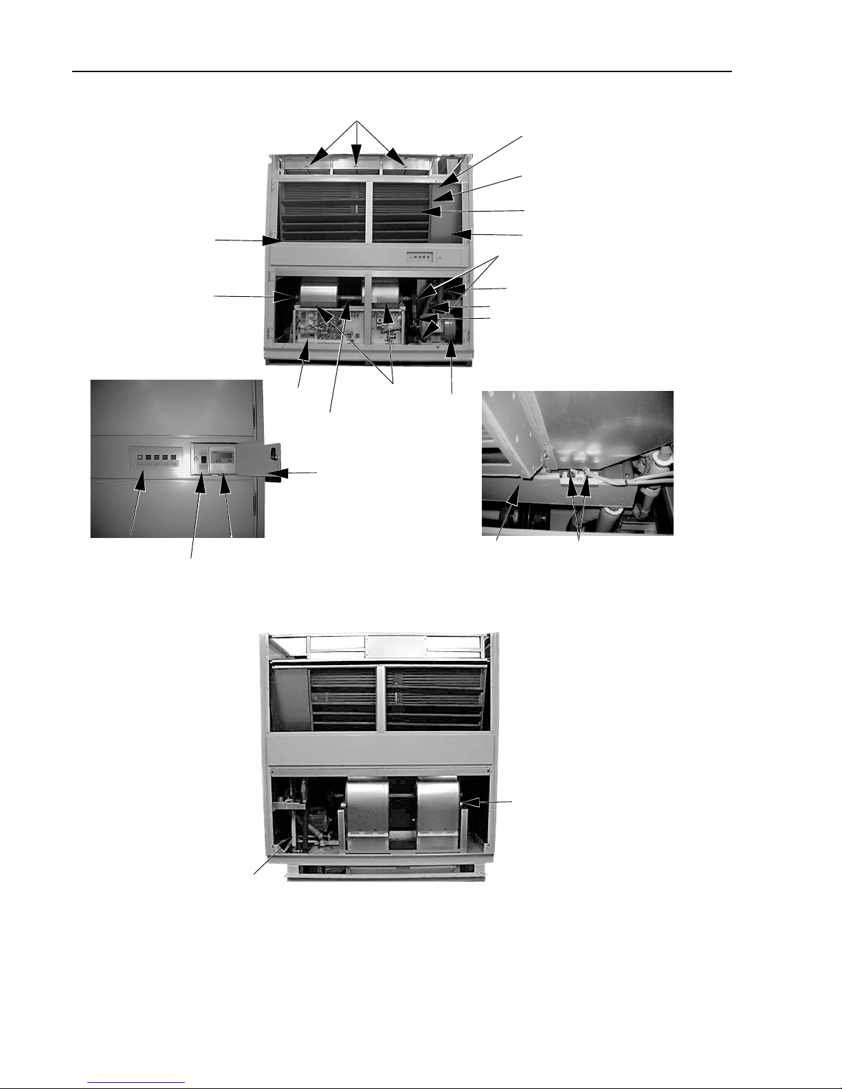
[1] Indoor Unit Components and Internal Structure
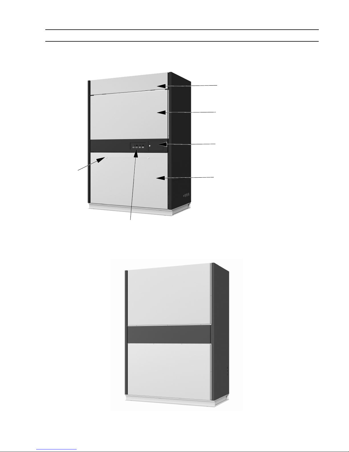
1. PFD-P250VM-E models
(1) Front view of a indoor unit
(2) Rear view of a indoor unit
Lock key X 2
Display lamp
Panel for refrigerant circuit maintenance
Panel for air filter maintenance
Operation panel (remote controller)
Panel for controller/fan related parts maintenance
Page 5
- 4 -
[ I Indoor Unit Components ]
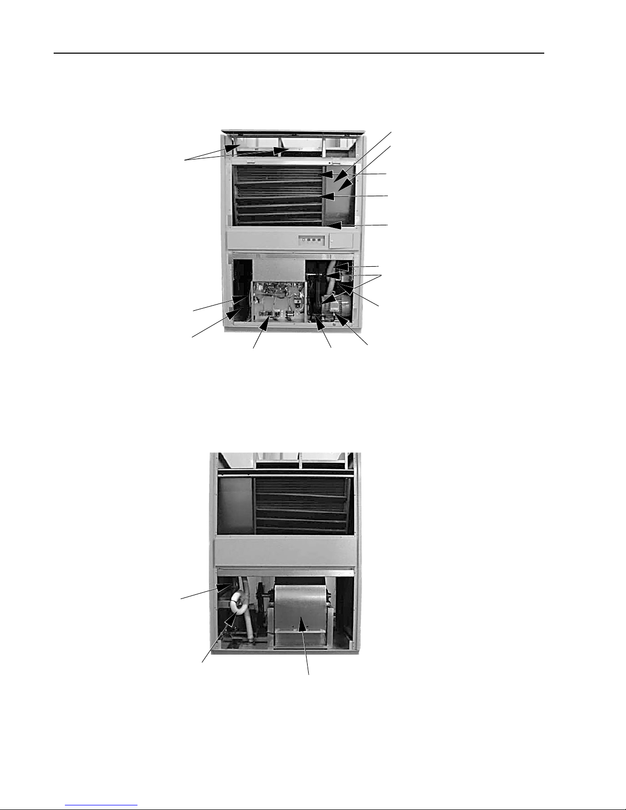
(3) Front view of internal structure
(4) Rear view of internal structure
Heat exchanger X 2 (front / back)
Sub drain pan
Suction temperature thermistor
(on the right side of heat exchanger)
Linear expansion valve (LEV)
Drain pan
Drain hose
Pulley X 2
Pipes (gas/liquid)
Fan motor
V belt
Controller
Air filter
Fan casing
(on the back of controller)
Discharge temperature thermistor
(on the left side of fan casing)
Drain hose
Pipes (ga /liquid)
Fan casing
Page 6
- 5 -
[ I Indoor Unit Components ]
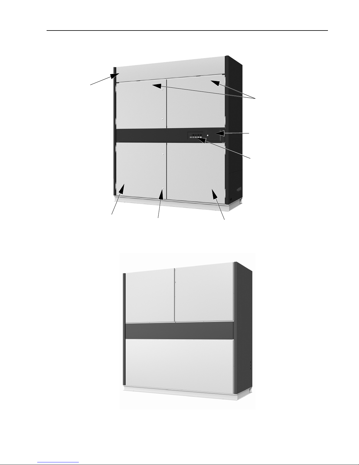
2. PFD-P500VM-E models
(1) Front view of a indoor unit
(2) Rear view of a indoor unit
Lock key X 4
Panel for controller maintenance
Display lamp
Operation panel (remote controller)
Panel for fan related parts maintenance
Panel for refrigerant circuit maintenance
Panel for air filter maintenance
Page 7
- 6 -
[ I Indoor Unit Components ]
(3) Front view of internal structure
(4) Rear view of a refrigerant circuit
Remote controller
Float switch X 2
Drain pan
Display lamp
Normal/inspection switching switch
Heat exchanger X 2 (front:No. 1; back:No. 2)
Sub drain pan
Suction temperature thermistor
(on the right side of heat exchanger)
Linear expansion valve (LEV)
Drain pan
Operation panel
Bearing
Drain hose
Pulley X 2
Pipes (gas/liquid)
Fan motor
V belt
<Location of drain pan overflow detection float switch>
Controller
Air filter
Fan casing
Discharge temperature thermistor
(on the left side of fan casing)
Bearing
Pipes (gas/liquid)
Page 8
- 7 -
[ I Indoor Unit Components ]
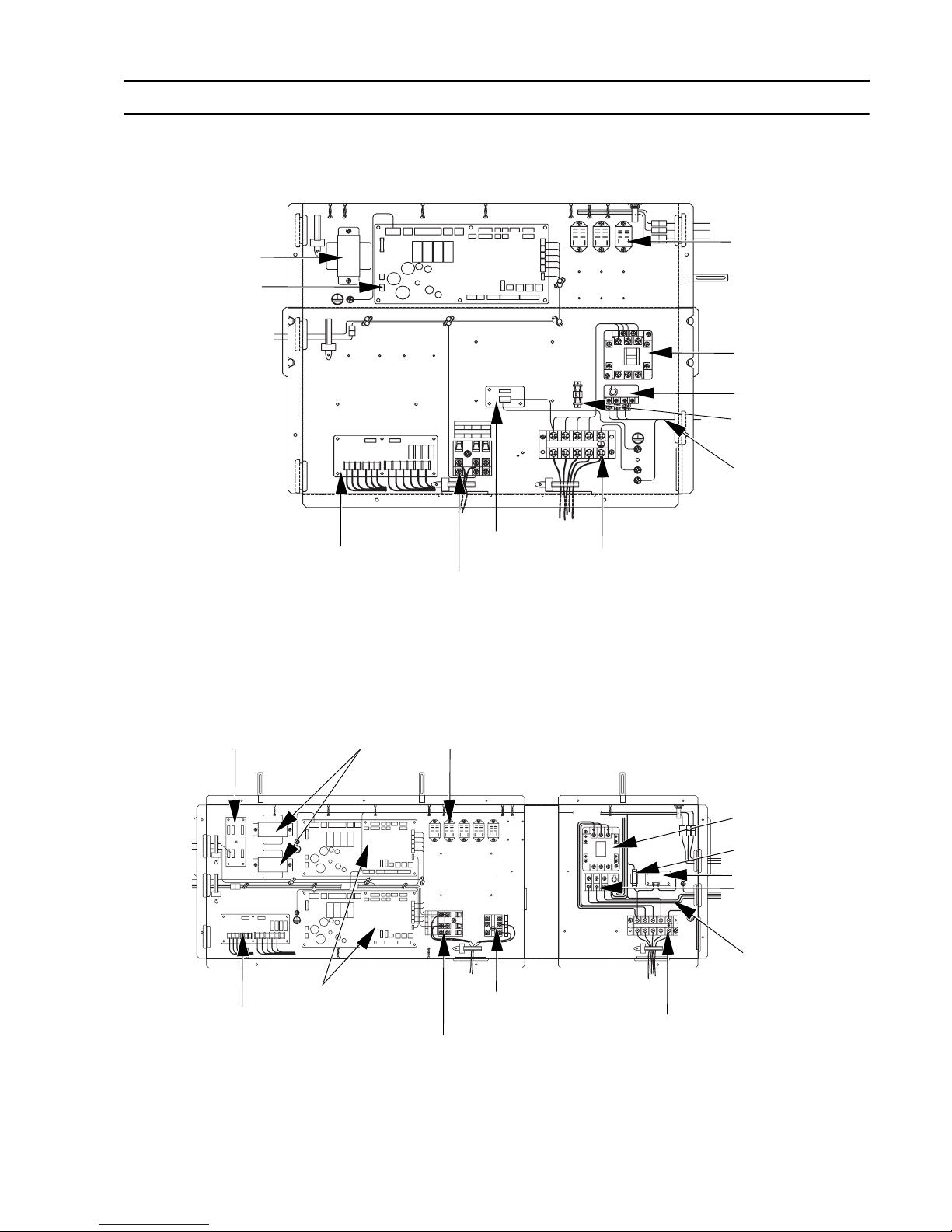
[2] Control Box of the Indoor Unit
1. PFD-P250VM-E models
2. PFD-P500VM-E models
Circuit board for external I/O
Terminal block for transmission line (upper)
Terminal block for MA remote controller (lower)
Power supply terminal bed
Surge absorber board
Motor wiring
Surge breaker (51F)
Fuse (F1)
Electro magnetic
contactor (52F)
Relay(X11,Z1,Z3)
Controller board
Transformer
Circuit board for external I/O
Terminal block for transmission line on No.2 side (upper)
Terminal block for MA remote controller (lower)
Power supply terminal bed
Terminal block for transmission
line on No.1 side
Motor wiring
Surge breaker (51F)
Electro magnetic
contactor (52F)
Relay(X11,X12,Z1,Z2,Z3)
Controller board
Transformer
Adapter board for LEV
Surge absorber board
Fuse (F1)
Page 9
- 8 -
[ I Indoor Unit Components ]
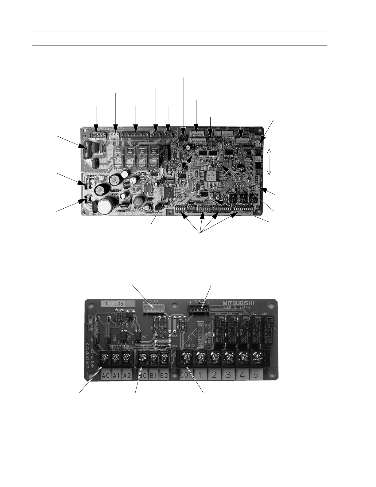
[3] Indoor Unit Circuit Board
1. PFD-P250,P500VM-E models
(1) Indoor Control Board
(2) External Input/Output Circuit Board
CND
Power supply
input
(AC 200V)
F901
Fuse
CN2M
Indoor unit
transmission
line
CN3T
Power supply input
(from transformer)
CNT
Power supply output
(to transformer)
CN90
Fan output
CNP
Drain pump
output
CN60
LEV output
SW1,2,3,4
Dip switch
CN24
Control signal
output
CN51
Switch input
LED1
LED2
CN31
Float switch input
CN32
Switch input
SWC
Switching between
discharge/suction control
Thermistor input
CN20
CN21
CN29
CN22
CN33
Lamp output
CN3A
Remote controller connection
CN53
Indoor control board (No.1)
To CN51
CN54
Indoor control board (No.2)
To CN51
TB22 (Relay contact output)
No.1 operation status
No.1 error status
No.2 operation status
No.2 error status
TB23 (Input with voltage)
ON/OFF
TB21 (Input no voltage)
ON/OFF
Page 10

- 9 -
II Refrigerant Circuit
[1] Principal Parts and Functions .......................................................................................... 11
Page 11

- 10 -
Page 12
- 11 -
[ II Refrigerant Circuit ]
II Refrigerant Circuit
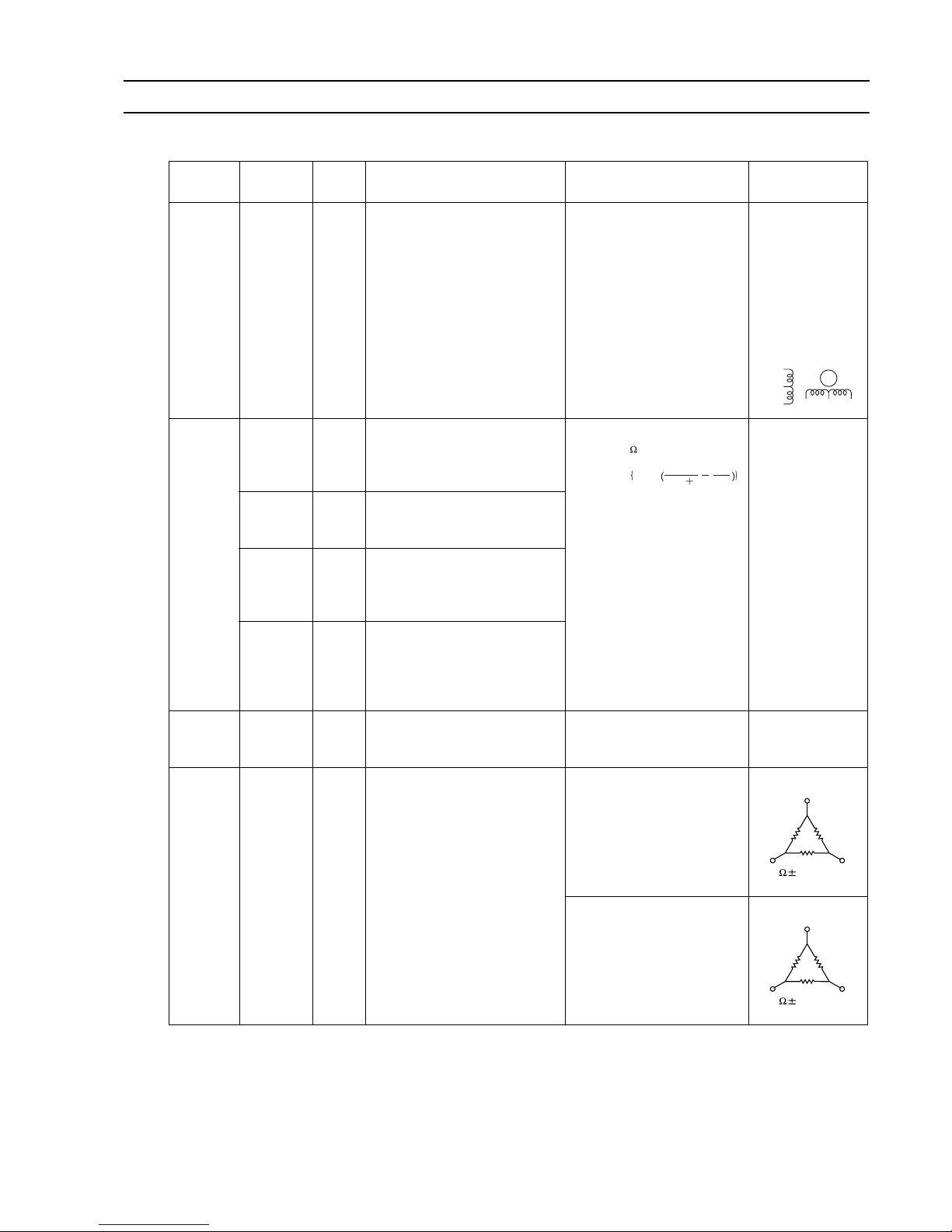
[1] Principal Parts and Functions
2. Indoor unit
(1) PFD-P250,500VM-E
Part
name
Symbols
(functions)
Notes Usage Specifications Check method
Linear expansion
valve
(LEV)
LEV 1.Adjusts superheat at the heat
exchanger outlet of the indoor
unit during cooling
2. Adjusts subcool at the heat
exchanger outlet of the indoor
unit during cooling
DC12V
Opening of a valve driven by
a stepping motor
0-(2000) pulses
Continuity check
with a tester
Continuity between white, red,
and orange.
Continuity between yellow,
brown, and blue.
Thermistor
TH21
(Suction
air temperature)
Indoor unit control (Thermo)
0°C : 15kohm
10°C :9.7kohm
20°C :6.4kohm
25°C :5.3kohm
30°C :4.3kohm
40°C :3.1kohm
Resistance check
TH22
(Pipe temperature)
Indoor unit control (Freeze prevention, Pre-heating stand-by)
TH23
(Gas pipe
temperature)
LEV control during cooling operation (Superheat detection)
TH24
(Discharge air
temperature)
Controls indoor unit discharge
(thermostat)
Float
Switch
33P1
33P2
Detects drain pan water level Contact Resistance:
Under 250 mohm
B contact type
Continuity check
with a tester
Motor MF Sends air PFD-P250VM-E
AC400V Type E 4P
Output 3.7kW
Resistance check
PFD-P500VM-E
AC400V Type B 4P
Output 5.5kW
Resistance check
YellowMBlueBrown
White
Red
Orange
R = 15k
0
R = 3460
R = 15
0/80
t
3460
273 t
1
273
1
exp
V
U
W
0.45 10%/2 phases
V
U
W
1.72 10%/2 phases
Page 13

- 12 -
[ II Refrigerant Circuit ]
Page 14

- 13 -
III Control
[1] Functions and Factory Settings of the Dipswitches ......................................................... 15
[2] Controlling the Outdoor Unit ............................................................................................ 20
[3] Operation Flow Chart....................................................................................................... 28
[4] Controlling the Indoor Unit ............................................................................................... 29
Page 15

- 14 -
Page 16

- 15 -
[ III Control ]
III Control
[1] Functions and Factory Settings of the Dipswitches
1. Outdoor unit
(1) Main board
Switch Function
Function according to switch setting Switch setting timing
OFF ON OFF ON
SWU 1-2 Unit address setting Set to 00 or 51-100 with the dial switch Before power on
SW1 1-10
For self-diagnosis/operation monitoring
Refer to the LED monitor display on
the outdoor unit board.
Anytime after power on
SW2
1- - - -
2
Deletion of connection information
Normal control Deletion Before power on
3
Deletion of error history SW
Storage of IC/OC
error history
Deletion of IC/OC
error history
Anytime after power on (When
switched from OFF to ON)
4
Refrigerant amount
adjustment
Normal control
Refrigerant
amount adjustment mode
Anytime after power on (Will be disabled 2 hours after compressor start
up except during initial start up mode)
5- - - -
6- - - -
7 Forced defrost Normal control
Forced defrost
starts
Anytime after
power on (When
switched from
OFF to ON)
10 minutes after
compressor startup
8 Defrost timer setting 50 minutes 90 minutes
Anytime after power on (When
switched from OFF to ON)
9- - - -
10 - - - -
SW3
1
Test run mode: enabled/disabled
SW3-2 disabled SW3-2 enabled Anytime after power on
2
Test run mode: ON/
OFF
Stops all ICs
Sends a test-run
signal to all IC
After power on and when SW3-1 is
on.
3
Defrost start temperature
-10°C
(-8 °C for 500
model unit)
-7°C
(-5 °C for 500
model unit)
Anytime after power on
4
Defrost end temperature
10°C
( 7°C for 500
model unit)
15°C
(12°C for 500
model unit)
Anytime after power on (except during defrost operation)
5- - - -
6 Pump down operation Normal control
Pump down operation
After power on and while compressor
is stopped
7
Target condensing
temperature on the
heating mode Tcm
49°C 53°C Anytime after power on
8- - - -
9- - - -
10 - - - -
Note: All are set to OFF at factory shipment.
Page 17

- 16 -
[ III Control ]
SW4
1- - - -
2- - - -
3- - - -
4
Reset of the integrated operation time Valid/Invalid
(comp 1 side)
Disabled Enabled Anytime after power on
5
Reset of the integrated operation time Valid/Invalid
(comp 2 side)
Disabled Enabled Anytime after power on
6- - - -
7- - - -
8- - - -
9- - - -
10
Dehumidification priority control Valid/Invalid
Enabled Disabled Anytime after power on
SW5
1- - - -
2
Rotation time under
two-refrigerant circuit
system
240hr 120hr Anytime after power on
3- - - -
4
Switching thermostat
control function
Valid Invalid Anytime after power on
5- - - -
6- - - -
7- - - -
8- - - -
9- - - -
10 - - - -
SWU
3
Reset of the integrated operation time
Resetting the integrated operation
time according to the settings of SW44 and 4-5
After power on. (when switching from
0 or 1 to 2)
Switch Function
Function according to switch setting Switch setting timing
OFF ON OFF ON
Note: All are set to OFF at factory shipment.
Page 18

- 17 -
[ III Control ]
(2) Compressor INV board
Note1 Except for SW2-1, all are set to OFF at factory shipment. Unless otherwise specified, set the switch to OFF
where indicated by "-," which may be set to a certain setting for a reason.
Note2 Leave SW1-1 to OFF during normal operation. If it is set to ON, errors cannot be detected and the unit may be
damaged.
(3) FAN INV board
Note: Except for SW2-1, all are set to OFF at factory shipment. Unless otherwise specified, set the switch to OFF where
indicated by "-," which may be set to a certain setting for a reason.
Switch Function
Function according to switch
setting
Switch setting timing
OFF ON OFF ON
SW1 1 Enabling/disabling the following error
detection functions;
ACCT or DCCT sensor circuit error
(530X Detail No. 115, 116)
ACCT or DCCT sensor failure
(530X Detail No.117,118)
IPM open/Disconnected CNCT2
(530X Detail No. 119)
Detection of erroneous wiring
(530X Detail No.120)
Error detection enabled
Error detection disabled
Anytime after power on
2 - - - - -
3 - - - - -
4 - - - - -
SW2 1 Inverter address 0 1 Always leave it to ON
2 - - - - -
3 - - - - -
4 - - - - -
Switch Function
Function according to switch
setting
Switch setting timing
OFF ON OFF ON
SW2 1 Inverter address 0 5 Always leave it to ON
2 - - - - -
3 - - - - -
4 - - - - -
Page 19

- 18 -
[ III Control ]
2. Function of the switch (Indoor unit)
(1) Dipswitches
[SW1,3,7]
[SW2,SW3-2,SW4]
[SW5]
Switch Function
Function according to switch setting
OFF ON
Switch setting timing
OFF ON
Notes
SW1
SW3
SW7
1
2
3
4
5
6
7
8
9
10
1
2
3
4
1
2
3
4
5
6
7
9
10
8
Clogged filter detection
Filter check reminder
time setting
Remote display option
External input
Operation switching
Capacity code
100h
Fan output
2500h
Thermo-ON signal
Available
Level
External input MA remote controller
Pulse
Not available Available
Not available Available
Not available Available
Refer to the combination with SW2
Not available
---
---
---
---
---
---
---
---
---
---
-
LEV setting conversion
function
Reset of the integrated
operation time
Valid/Invalid (fan belt)
Reset of the integrated
operation time
Valid/Invalid (fan motor)
--
---
---
-
--
---
While the unit is stopped
(Remote controller OFF)
Note 1. Setting timing for DIPSW 1 and 3 is during unit stoppage (remote controller OFF). It is not necessary to reset the settings by power-off.
Note 2. Settings in the shaded areas are factory settings.
Model System
Capacity code
SW3-2
123456
P250
50 OFF
ON
OFF
P500
Two-refrigerant circuit connection
One-refrigerant circuit connection
One-refrigerant circuit connection
100
50
ON
OFF
SW2 SW4
12345
ON
OFF
ON
OFF
ON
OFF
ON
OFF
ON
OFF
*
* The setting is changed at site under two-refrigerant circuit connection
<Capacity code and function setting>
If the capacity code or the function is set wrongly when the circuit board is replaced, reset the power of both the indoor unit and the outdoor unit.
Function
Switch setting timing
During unit stoppage (remote controller OFF)
(when switching from OFF to ON)
Reset of the integrated
operation time
Resetting the integrated operation time
according to the setting of SW7-1 and 7-2
Operation by switch setting
Page 20

- 19 -
[ III Control ]
[SW8]
(2) Slide switches
3. Function of the switch <Remote controller>
MA remote controller (PAR-20MAA)
The SW is located at the bottom of the remote controller under the cover. Operate the switches to perform the remote
controller main/sub setting or other function settings. Normally, do not change the settings of switches other than the SW1
(main/sub switching switch). (All the switches are set to "ON" at factory setting.)
Anytime
after power on
1
Normal control
Compulsory thermo OFF
23
Compulsory thermo OFF setting during test run
(used in the grouped indoor units connected to
different outdoor units)
ON
OFF
ON
OFF
Function Operation by switch setting
Switch setting timing
Switch Function Operation by switch setting
Switch setting timing
SWC 1~2
Switching between
suction/discharge temperature
control
Anytime
after power on
Option
Standard
Option
Standard
Input setting
Suction temperature control
Discharge temperature control
*
* The settings for the two circuit boards must be equivalent to switch between suction/discharge temperature control under
two-refrigerant circuit system.
Remote controllerSwitching switch
1ON234
Switch
2
1
Function
Remote controller
main/sub setting
At power on of the
remote controller
Normal
startup
Timer mode
startup
3
Cooling/heating display
set by automatic setting
Displayed Not displayed
4
Suction temperature display
(discharge temperature display)
Displayed Not displayed
Operation by switch settings
Switch setting timing
ON OFF
Main Sub
Before power on
Before power on
Before power on
Before power on
When two remote controllers are connected
to one group, set either of the remote
controllers to "Sub".
To resume the operation with timer mode
after the power is restored when the
schedule timer is connected, set to
"Timer mode startup".
When the automatic mode is set and the
"Cooling"/"Heating" display is not necessary,
set to "Not displayed".
When the suction temperature (discharge
temperature) display is not necessary,
set to "Not displayed".
Page 21

- 20 -
[ III Control ]
[2] Controlling the Outdoor Unit
-1- Initial Control
When the power is turned on, the initial processing of the microcomputer is given top priority.
During the initial processing, control processing of the operation signal is suspended. The control processing is resumed
after the initial processing is completed. Initial processing involves data processing in the microcomputer and initial setting
of each of the LEV opening. This process will take up to 2 minutes.
During the initial processing, the LED monitor on the outdoor unit's main board displays S/W version -> refrigerant type
-> heat pump -> cooling only and capacity -> and communication address in turn every second.
-2- Control at Start-up
The upper limit of frequency during the first 3 minutes of the operation is 50 Hz.
When the power is turned on, normal operation will start after the initial start-up mode (to be described later) has been
completed (with a restriction on the frequency).
-3- Bypass Control
Bypass solenoid valves (P250,SV1; P500,SV1,SV3), which bypass the high- and low- pressure sides, perform the following functions.
(1) Bypass solenoid valve (SV1) (ON = Open)
[Example of an SV1 operation]
(2) Bypass valve (SV3, P500 model only) (ON = Open)
The opening of SV3 is controlled by the operating state of No.1 and No.2 compressors.
Operation
SV1
ON OFF
At No. 1 compressor start-up or at No. 2
compressor start-up
(P500 model only)
ON for 4 minutes.
After the restoration of thermo or 3 minutes
after restart
ON for 2 minutes.
During cooling or heating operation with the
compressor stopped
Always ON.
Exception: OFF when HPS-LPS is 0.2 MPa or less
After the operation has stopped ON for 3 minutes.
Exception: OFF when HPS-LPS is 0.2 MPa or less
During defrost operation
(See *1 in the figure below.)
Always ON
During oil-recovery operation Always OFF during cooling operation and always ON during heating op-
eration when running an oil-recovery operation after running a continuous
operation at low frequency.
During an operation with the compressor
running at 30 Hz (After 3 minutes have
passed since start-up)
When low pressure (LPS) drops
below 0.23 MPa.
When low pressure (LPS) exceeds
0.38 MPa.
When high pressure (Pd) rises When Pd exceeds
3.77 MPa
When Pd is or below
3.43 MPa and 30 seconds have
passed
No.1 Compressor No.2 Compressor SV3
Stopped Stopped OFF
In operation Stopped ON
In operation In operation OFF
Startup
Thermo. Thermo. Defrost
time
(*1)
Stopped
OFF ON
Compressor
Bypass solenoid
valve (SV1)
(4-min.) (2-min.) (8-min.)
(3-min.
)
Page 22

- 21 -
[ III Control ]
-4- Compressor Frequency Control
Depending on the capacity required, the frequency of the compressor is controlled to bring the evaporation temperature
(Te) close to the target evaporation temperature (Tem) during cooling operation, and to keep constant condensing temperature (49°C =2.88MPa) during heating operation.
The target evaporation temperature (Tem) varies as follows during cooling operation depending on the capacity required.
When lacking in capacity : Tem is lowered
When the capacity exceeds the needs : Tem is raised
Minimum and maximum Tem Valued : -10°C Tem 25°C
For P250 models, the capacity is controlled by only the inverter-driven compressor, and for P500 models, the capacity is
controlled by the compressor No.1 (inverter-driven) and No.2 (constant capacity).
The following table shows the frequency change of the inverter compressor during normal operation.
(1) No. 2 compressor operation/stop (P500 model only)
No.2 compressor changeover from stop to in-operation
When No.1 compressor does not meet the capacity requirement, No.2 compressor will start its operation.
No.2 compressor changeover from stop to in-operation
When an operation of both No.1 and No.2 compressors exceeds the capacity requirement, No.2 compressor will stop
its operation.
(2) Pressure limit
The maximum limit of high pressure (Pd) is set for each frequency level. If this limit is exceeded, the frequency will be
reduced every 30 seconds.
(3) Discharge temperature limit
The discharge temperature (Td) of the compressor in operation is detected, and if it exceeds the upper limit, the frequency
is reduced by 5 Hz.
Control is performed 30 seconds after compressor start-up and every 30 seconds thereafter.
Operating temperature is 115°C
(4) Periodic frequency control
Frequency control other than the ones performed at start-up, upon status change, and for protection is called periodic
frequency control (convergent control) and is performed in the following manner.
[Periodic control cycle]
Periodic control is performed after the following time has passed
30 seconds after either compressor start-up or the completion of defrost operation
30 seconds after frequency control based on discharge temperature or pressure limit
[The amount of frequency change]
The amount of frequency change is controlled to approximate the target value based on the evaporation temperature
(Te) and condensing temperature (Tc).
Model Frequency/cooling Frequency/heating Speed
P250 model 20-60 Hz 20-60Hz 3 Hz/second
P500 model 20-70 Hz 20-70 Hz 3 Hz/second
The maximum frequency during heating operation is affected by the outdoor air temperature to a certain extent.
Page 23

- 22 -
[ III Control ]
-5- Defrost Operation Control
(1) Starting the defrost operation
Defrost operation is started when the pipe temperature (TH5) of -10°C or below (-8°C or below for P500-type) has con-
tinuously been detected for 3 minutes after the integrated compressor operation time of 50 minutes have passed (90 minutes when the defrost prohibit timer is set to 90 minutes).
If 10 minutes have passed since compressor start-up or since the completion of defrost operation, forced defrost opera-
tion will start by turning on the forced defrost switch (DIP SW2-7).
Even if the defrost prohibit timer is set to 90 minutes, the actual defrost prohibit time for the next operation will be 50
minutes if defrosting took 12 minutes.
(2) Defrost operation
(3) Stopping the defrost operation
Defrost operation will stop when 12 minutes have passed since the beginning of defrost operation (15 minutes when the
defrost prohibit timer is set to 90 minutes), or when the piping temperature (TH5) of 10°C or above has been continuously
detected for 2 minutes (TH5 above 7°C for 2 minutes for P500 model and above).
Defrost operation will not stop its operation for 2 minutes once started unless the piping temperature exceeds 25°C within
2 minutes, in which case the operation will stop (Above 20°C within 2 minutes for P500 model and above).
(4) Problems during defrost operation
If a problem is detected during defrost operation, the operation will be stopped, and the defrost prohibition time based on
the integrated compressor operation time will be set to 20 minutes.
Compressor frequency Model No.1 Compressor No.2 Compressor
P250 model 53 -
P500model
(50/60 Hz)
70/60 ON (50/60 Hz)
Outdoor unit fan Stopped
SV1 ON
SV3 (P500 model only) ON
21S4a OFF
21S4b (P500 model only) OFF
SV4c (P500 model only) OFF
21S5b (P500 model only) OFF
21S5c (P500 model only) OFF
LEV1 480 pulses
Page 24

- 23 -
[ III Control ]
-6- Refrigerant Recovery Control
Recovery of refrigerant is performed during heating operation to prevent the refrigerant from accumulating inside the unit
while it is stopped (unit in fan mode), or inside the indoor unit that is in cooling mode or in heating mode with thermo off. It
is also performed during cooling operation to prevent an excessive amount of refrigerant from accumulating in the outdoor
heat exchanger.
(1) During heating operation
[Starting refrigerant recovery mode]
The refrigerant recovery mode in heating starts when all of the following three conditions are met:
15 minutes have passed since the completion of previous refrigerant recovery.
Td > 105°C
Frequencies below 50 Hz
[Refrigerant recovery]
1) Refrigerant is recovered with the LEV on the applicable indoor unit (unit under stopping mode, fan mode, cooling,
heating with thermo off) being opened for 15 seconds.
2) Periodic capacity control of the outdoor units and periodic LEV control of the indoor units will be suspended during
refrigerant recovery operation; they will be performed after the recovery has been completed.
3) Defrost operation will be suspended until refrigerant recovery has been completed.
(2) During cooling operation
[Starting refrigerant recovery mode]
The refrigerant recovery mode starts when all the following conditions are met
30 minutes have passed since the completion of previous refrigerant recovery.
When the unit keeps running for 3 minutes in a row or more with high discharge temperature
Td > 105°C or
Pd > 3.43 MPa (35 kg/cm
2
G) and SC0 > 10 deg°C
[Refrigerant recovery]
Increase the opening of LEV1 (Periodic control begins when 30 seconds have elapsed).
Opening of LEV during refrigerant recovery
(Opening of indoor unit LEV: 500 pulses)
Initial opening of LEV
Start Finish
15 seconds
Page 25

- 24 -
[ III Control ]
-7- Capacity Control of Outdoor Fan and Heat Exchanger
(1) Control method
The outdoor fan air flow rate is controlled to keep constant evaporation temperature during cooling operation and to keep
constant condensing temperature during heating operation.
The capacity of the heat exchanger on the P500 models of outdoors is controlled by the 4-way valve (21S4b) or the so-
lenoid valve (SV5b).
(2) Control
Outdoor unit fan stops while the compressor is stopped (except in the presence of input from snow sensor).
The fan operates at full speed for 5 seconds after start-up.
The outdoor unit fan stops during defrost operation.
(3) Capacity control of outdoor heat exchanger
Notes:
The unit runs a cooling cycle when 21S4b and 21S4c are not powered and runs a heating cycle when it is powered.
SV5b and SV5c are open when it is not powered and is closed when it is powered.
While the unit is stopped, 21S4b and 21S4c are not powered cooling cycle, and SV5b and SV5c are open.
-8- Subcool Coil Control (Linear Expansion Valve <LEV1>)
The amount of super heat is controlled and kept constant based on the bypass outlet temperature (TH8) of subcool coil
every 30 seconds.
The degree of opening is controlled based on the subcool coil outlet/inlet temperature (TH5, TH7), high pressure (Pd), and
discharge temperature. The LEV will be closed (0) during heating operation and when the compressor is stopped, and it
will be open during cooling operation with Thermo off.
The LEV stays open at 480 during defrost operation.
[P500 models]
Operation
mode
Heat exchanger
capacity
Number of fans Inverter control Notes
Cooling 50% 1 5-100% 21S4b ON, 21S4c OFF
SV5b ON, SV5c OFF
100% 2 10-100% 21S4b OFF, 21S4c OFF
SV5b OFF, SV5c OFF
Heating 100% 2 10-100% 21S4b ON,21S4 ON
SV5b OFF, SV5c OFF
Defrost 100% 0 0% 21S4b OFF, 21S4c OFF
SV5b OFF, SV5c OFF
Page 26

- 25 -
[ III Control ]
-9- Control at Initial Start-up
When the unit is started for the first time, it will run the following course of operation.
(1) Flow chart of initial operation mode
(2) Initial start-up control of P500 models: time chart
Example
(3) Caution for Test Run
In the first test run after the power-on, a compressor operates for start-up confirmation. It's not a failure even if the compressor alternate between start and stop. This operation will be finished in 70 minutes maximum. The flag 7 of the service
LED lights during this operation by setting the self-diagnosis switch (SW1) as below.
Start of initial operation mode
Step 1
P250
P500
Operation of No.1 compressor only
Exception : Completed if discharge superheat reaches above 25
C within
5 minutes of start-up.
Step 3
Forced operation of only No.2 compressor only
Completed in the integrated operation time of 5 minutes
Completion of initial operation mode
f 60 Hz. Completed in the integrated operation time of 25 minutes.
60 Hz or less for the first 30 minutes , 85 Hz or less after 30 minutes.
No.2 compressor not in operation.
Completed in the integrated operation time of 40 minutes.
:
:
P500 types
P250 types
No.1 compressor
ON/OFF
No.2 compressor
ON/OFF
Completion of initial operation mode
40 minutes
Step 1 Step 3
5 minutes
12345678910
ON
OFF
Page 27

- 26 -
[ III Control ]
-10- Emergency Operation Mode
When compressors (No.1 or No.2) fails, the unit goes into the emergency operation mode to respond to the problem. The
unit can be put into this mode by performing an error reset on the remote controller.
(1) Starting the emergency operation
1) When an error occurs, the error source and the error code will be displayed on the display on the remote controller.
2) When the error type displayed in 1 above allows the unit to run the emergency operation (as shown in the table
below), the retry operation will start automatically.
(2) Ending the emergency operation
1) End conditions
When one of the following conditions is met, emergency operation will end.
When an error is reset
*When resetting an error with the remote controller or the external input
When an error is detected that does not allow the unit to run the emergency operation.
(3) Miscellaneous
1) End conditions
When encountering problems other than the ones listed above, the system makes an error stop without performing
emergency operation. (Only the indoor fan operates unless problems are found with the fan.)
When problems are found in only one of the two units of a 2-refrigerant circuit, only the unit with the problems will run
an emergency operation or stop its operation, and the other unit will keep running its operation.
Emergency operation is intended only as a first aid until the unit is serviced. Have the unit serviced without delay to
restore a normal operation.
Pattern of
emergency
operation
mode
Error
source
Type of error that allows the unit to go
into the emergency operation
Type of error
that does not al-
low the unit to
go into the
emergency op-
eration
Operation
At malfunction of No.1
(INV)
Outdoor
unit
Heatsink thermistor
<Inverter error>
Overcurrent break
Overload protection
Heatsink overheat protection
Cooling fan abnormality
Bus voltage drop protection
IDC sensor/circuit error
VDC sensor/circuit error
THHS sensor/circuit error
IPM communication error
4230
4250
4240
4230
4260
4220
5301
4200
5110
0403
All errors other
than the ones
listed on the left
Emergency operation with only
No.2 compressor
At malfunction of No.2
Overcurrent protection 4108 Emergency operation with only
No.1 compressor
Thermistor
error
TH5
TH7
TH8
5105
5107
5108
Page 28

- 27 -
[ III Control ]
-11- Capacity Control between Outdoor Units (when two refrigerant circuits are connected)
The following two capacity control methods between indoor units are available.
Control to make only one of the outdoor units (which has the smaller address) operate and keep running during low-load
hours at startup.
Control to make one of the outdoor units stop, and the other outdoor unit operate when the load becomes low during
normal operation. After a certain period of time has passed since only one of the outdoor units started operation, the unit
in operation stops, and the other outdoor unit starts operation automatically.
(1) Starting Conditions
When it is determined that the load is less than 50%, using suction temperature as a reference.
Operation frequencies of both indoor and outdoor units remain near the minimum level three minutes after start-up.
(2) Stopping Conditions
When operation frequency of the running unit rises up near the maximum capacity.
When it is determined that the load is over 50%, using suction temperature as a reference.
When compressor stops while running only one unit.
-12- Dehumidification priority control
The dehumidification priority control is the control to increase the amount of dehumidification by increasing the frequency
of the compressor when the external signal (dehumidification command) is received during cooling operation.
During dehumidification priority control, the room temperature may drop below the preset temperature set during normal
operation.
Under this control, the set temperature wil be compulsory at the minimum value.
(Under discharge temperature control:14°C Under suction temperature conrol:19°C)
The temperature nor the humidity can be controlled simultaneously as the reheat function is not available.
-13- Operation Mode
(1) Indoor unit operation mode
The operation mode can be selected from the following 4 modes using the remote controller.
(2) Outdoor unit operation mode
Note:
The heating mode can be used for standby of the indoor unit when the outdoor temperature is low. Confirm that the devices to be cooled are not influenced by the heat.
The discharge temperature control cannot be used.
The discharge temperature is controlled not to drop less or equal 30°C. It may take time to reach the indoor target temperature.
When the indoor temperature reaches the cooling operation range, switch the operation from heating to cooling.
1 Cooling mode
2 Heating mode
3Fan mode
4 Stopping mode
1 Cooling mode All indoor units in operation are in cooling mode.
2 Heating mode All indoor units in operation are in heating mode.
3 Stopping mode All indoor units are in fan mode or stopping mode.
Page 29

- 28 -
[ III Control ]
[3] Operation Flow Chart
(1) Heating operation (For warming up the indoor unit)
Heating operation
Test run mode
ON
Thermostat ON
Defrost
operation
3-minute restart
prevention
*Note 1,2
*Note 1,2
YES
YES
YES
YES
YES
NO
NO
NO
NO
NO
1. Indoor/outdoor unit fan control
2. I
nverter frequency control
3. Indoor unit LEV, LEV1 control
4. Solenoid valve control
5. 52C control
Normal operation
Defrost operation
4-way valve ON
During test run mode
1.
Indoor unit fan operation at
Very Low speed
2. Inverter output 0Hz
3.
Indoor unit LEV, LEV1 Fully closed
4. All solenoid valves OFF
5. Outdoor unit fan stop
6. 52C OFF
4-way valve OFF
Stopping the
defrost operation
Stopping the defrost
operation
Return to heating
operation
1. Indoor unit fan stops
2.
I
nverter defrost frequency control
3.
Indoor unit LEV fully closed.
4. Solenoid valve control
5. Outdoor unit fan stop
6. LEV1 control
7. 52C control
*Note 1. When outdoor unit starts defrosting, it transmits defrost operations command to indoor unit, and the indoor unit starts
defrosting operations. Similarly when defrosting operation stops, indoor unit returns to heating operation after receiving
defrost end command of outdoor unit.
*Note 2. Defrost end condition: 10 or more minutes must pass after defrost operation.
or
Outdoor unit piping temperature: refer to "-5-. Defrost operation control" of [2] Controlling the Outdoor Unit.
Note 3. Refer to "-5-. Defrost operation control" of [2] Controlling the Outdoor Unit for indoor fan control.
Note 4. The discharge temperature is controlled to keep approx. 30 C or below in heating mode.
Unit in the stopped state
Page 30

- 29 -
[ III Control ]
[4] Controlling the Indoor Unit
(2) Thermostat Reading
(1) Thermostat Functions and Function Selection
A. Discharge temperature control (SWC is set to "Standard".)
-1- Thermostat Functions
<Indoor unit control>
There are two controller circuit boards with two refrigerant circuits inside the indoor unit or 16 and 20 HP.
There is one controller circuit board with one refrigerant circuit. Each refrigerant circuit is controlled independently
(in case of one refrigerant circuit, one-to-one control of indoor unit and outdoor unit) in the following method.
When only the controller circuit board No. 1 with one refrigerant circuit is equipped inside the indoor unit of 16 or 20 HP,
the following control is performed.
(a) Thermo ON Condition
• Three minutes have past since thermo OFF AND
• TH24
•Two control methods are available; suction temperature control and discharge temperature control.
•The suction/discharge temperature control can be switched by the switches (SWC) on the controller circuit board
inside the controller of the indoor unit.
•The discharge temperature control is selected (SWC is set to "Standard") at factory shipment.
•To switch the control, set SWC on controller circuit board inside the controller as follows.
•The SWC settings made on two controller circuit boards must be equivalent.<20HP only>
*Only the suction temperature control is performed in the heating mode regardless of the SWC settings.
To perform suction temperature control: Set SWC to "Option".
To perform discharge temperature control: Set SWC to "Standard".
- Target Temperature >1 C AND
• TH21 is higher than when thermo is OFF.
TH24: Discharge thermistor
TH21: Suction thermistor
(b) Thermo OFF Condition
< When Dipsw5-4 on the outdoor unit is ON >
• 30 minutes have past since thermo ON AND
• TH24 - Target Temperature < -1 C has been detected for 10 minutes
OR TH24 - Target Temperature < 15 C was detected
< When Dipsw5-4 on the outdoor unit is OFF >
When Dipsw5-4 on the outdoor unit is ON >
When Dipsw5-4 on the outdoor unit is OFF >
• Two minutes have past since thermo ON
• TH24 - Target Temperature < -1 C has been detected for 5 minute AND F=Fmin.
B. Suction Temperature Control (SWC is set to "Option".)
(a) Thermo ON Condition
• Three minutes have past since thermo OFF AND
• T
H21 - Target Temperature > 1 C
(b) Thermo OFF Condition
<
• Thirty minutes have past since thermo ON AND
• TH21 - Target Temperature < -1 C has been detected for 10 minutes OR TH21 - Target
Temperature < -5 C was detected.
<
• Two minutes have past since thermo ON AND
• TH21 - Target Temperature < -1 C has been detected for 5 minute AND F=Fmin.
Page 31

- 30 -
[ III Control ]
-2- Actuator Control
(1) LEV Control
•W
• The degree of LEV opening is set to the initial degree depending on the condensing pressure at start-up.
• When the operation is stopped by the remote controller or by the external input
• After the start-up, the degree of LEV opening is controlled every minute so that the superheat detected by
the thermistors TH22 (liquid pipe) and TH23 (gas pipe) of the indoor unit can be within a certain range.
• The degree of LEV full opening/closing is 41 pulses.
• Depending on the operating condition of the outdoor unit, a control other than the superheat control described
above may be performed.
The unit makes an error stop when the contact point (B contact) of the float switch loses its contact
(i.e. loosened floated parts, disconnected wire, unfastened connector etc.) for more than 1 minute or longer.
hen suction or discharge temperature nears the target temperature, superheat control value rises and
LEV opening narrows.
(2) Fan Control
Whether the thermostat is ON or OFF, the fan stays ON except during operation stoppage.
Exception: Fan stops when problem with the fan is detected (Error Code 4109).
* Fan problems may be experienced in the following situations: Surge breaker trip (51F) or malfunctions
of sub relays (Z1, Z2, or Z3.)
(3) Float Switch Control
(4) Indicator Lamp
Indicator lamps on the front side of the unit indicate the operation status of the indoor unit.
Power Supply Lamp (White) : Lit upon power ON. Extinguished upon power OFF.
Operation Lamp (Green) : Lit during operation. Extinguished during stoppage.
Error
Inspection lamp (orange)
Lamp (Red) : Lit when errors are detected in each refrigerant circuit. Extinguished during
normal operation or after error reset.
: Lit when the inspection switch of the indoor unit is ON (during inspection).
Extinguished when the switch is OFF (during normal operation).
-3- Temperature Setting Range
The temperature range can be set between 19 C (14 C) and 30 C using the remote controller when the suction
temperature control (or the discharge temperature control) is performed.
* Depending on the operating conditions, target temperature and actual discharge/suction temperatures may
not match. For example, even if the target discharge temperature is set at 14 C, if the load exceeds the
capability of the unit, the actual temperature will not reach 14 C.
-4- Emergency Operation Mode
The emergency operation is an operation that operates the unit temporarily depending on the error types
described later. The emergency operation is run automatically when the following errors are detected.
(1) Starting an Emergency Operation
When the following problems are detected, the system runs an emergency operation, displaying error codes.
During this operation, near normal operation is run, ignoring the following abnormal operation data. (Some
of the actuator will run at a fixed state during this time.)
(2) Stopping the Emergency Operation
Emergency operation mode is stopped in the following situations:
When
A different type of error is detected during emergency operation
When emergency operation disabled error is detected
abnormal mode is reset
*How
* i.e. when TH22 error is detected during emergency operation caused by TH21 error
to reset an abnormal mode
Error codesTypes of Errors
TH21
TH22
TH23
TH24
Thermistor Error Open/Short Detection 5101
5102
5103
5104
Chart: Types of errors in which emergency operation can be run
Page 32

- 31 -
[ III Control ]
(3) Miscellaneous
When the errors other than described in the chart, the unit makes an error stop without performing emergency
operation. (Only the indoor fan operates, however; it stops when the fan is in trouble.)
When one of the two refrigerant circuits, the outdoor unit with the refrigerant circuit in error performs emergency
operation or makes an error stop, while the other outdoor unit keeps normal operation.
Emergency operation is intended only as a first aid until the unit is serviced. Have the unit serviced without delay to restore a normal operation.
-5- Twenty-second restart-suspension mode
The unit will be in a twenty-second restart-suspension mode (same operation as Thermo
OFF) in any of the fol-
lowing situations.
• When the demand for outdoor unit changes from Thermo ON to Thermo OFF.
• When operation mode changes from normal to emergency mode.
• When anti-freeze mode is completed.
* The outdoor unit has also a twenty-second restart-suspension mode, and it works separately from the
indoor unit.
* In heating mode, the mode changes to three-minute restart-prevention mode.
-6- Anti-Freeze Control (In cooling mode)
(1) Starting Conditions
This operation will start when all of the following conditions are met:
• Thermo ON status has been detected for 16 minutes.
• TH22 (liquid pipe temp. Thermistor) < 1 C has been detected for 20 minutes.
(2) Control Operation
The unit will be in the same condition as Thermo OFF condition for six minutes. When the following conditions
are met, the unit will be in a 20-second restart-suspension mode.
(3) Stopping Conditions
When either of the following conditions is met:
• TH22
10 C
• Six minutes have elapsed since the beginning of this operation.
Page 33

- 32 -
[ III Control ]
-7- Switching Between Pulse and Level of MA Remote Controller External Input
The start/stop operation can be performed by either of the MA remote controller or the external input (pulse/level).
Input
DIPSW on the address circuit board (No.1 and No. 2)
Function
Start/Stop
Usage
Sending ON/OFF command
to the indoor unit
Signal specifications
Pulse
(With-voltage/No-voltage a-contact)
<In case of with-voltage>
Power supply:12~24V DC
Electrical current:10mA (12V DC)
(Pulse powering time) (Pulse interval)
<Pulse specification>
200ms
Valid operation
External input (level)
External input (pulse)
MA remote controller
SW1-10 = ON
SW1-10 = OFF
SW1-9 = OFF
SW1-9 = ON
* For the MA remote controller and the external input, the operation command sent later has no priority.
* When the Normal/Inspection switch on the main unit is set to "Inspection", the external input will be disabled.
Only the operation performed by the MA remote controller is valid.
* Use a contact point for small electrical current (12V DC 1mA).
-8- Operation during Electrical Power Failure
After the controller in this air conditioning unit receives signals indicating power failure or an instantaneous
drop in voltage, unless the unit receives a command not to restart, it will resume its operation after power
supply is restored.
Depending on the duration of power outage, the following operations will be run.
Note 1: When indoor unit is in the maintenance mode , it will not resume operation even
after the power has
been restored.
Note 2: After the unit resumes its operation, MA remote controller will display ’HO’ for fifteen seconds, during
which time the MA remote controller will not respond. To turn off the unit during this time, turn off the
power with an electric leak breaker.
Duration of Power Outage Unit Operation
Shorter than 6msec Both indoor and outdoor units will stay on.
Longer than 6msec and
Shorter than 50msec
(Note1, Note2)
It is recognized by the unit as aninstantaneous power outage
Indoor Unit: The fan stays on.
Outdoor Unit: Compressor stops, then resumes its operation 20 seconds later.
Longer than 50msec
(Note1, Note2)
It is recognized by the unit as power outage.
Air-conditioning unit will stop (incl. fan and compressor).
It will resume operation after the power has been restored.
* The unit operation is resumed after 20 seconds plus "half of the indoor unit address"
seconds (40 seconds at maximum) have passed since the power has been restored.
200ms
Page 34

- 33 -
IV Test Run Mode
[1] Items to be checked before a Test Run........................................................................... 35
[2] Test Run Method ............................................................................................................. 36
[3] Standard Operation Data (Reference Data) .................................................................... 37
Page 35

- 34 -
Page 36

- 35 -
[ IV Test Run Mode ]
IV Test Run Mode
[1] Items to be checked before a Test Run
1 Check for refrigerant leak and loose cables and connectors.
2 Measure the insulation resistance between the power supply terminal block and the ground with a 500V megger and make
sure it reads at least 1.0Mohm.
Caution:
(1) Do not operate the unit if the insulation resistance is below 1.0Mohm.
(2) Do not apply megger voltage to the terminal block for transmission line. Doing so will damage the controller board.
(3) The insulation resistance between the power supply terminal block and the ground could go down to close to 1Mohm
immediately after installation or when the power is kept off for an extended period of time because of the accumulation
of refrigerant in the compressor.
(4) If insulation resistance reads at least 1Mohm, by turning on the main power and powering the crankcase heater for at
least 12 hours, the refrigerant in the compressor will evaporate and the insulation resistance will go up.
(5) Do not measure the insulation resistance of the terminal block for transmission line for the unit remote controller.
3 Make sure that the stop valve on the gas pipe, liquid pipe, and oil balance pipe are fully open.
Caution: Securely tighten the cap.
4 Check the phase sequence and the voltage of the 3-phase power supply.
Caution: If an open phase or a reverse phase is detected, it will be treated as an abnormal stop during test run (4103
error).
5 [When the power supply extension unit for transmission line is connected]
Turn on the power of the power supply extension unit for transmission line before turning on the power of the outdoor
unit.
Caution:
(1) When the power of the outdoor unit is turned on first, the system connection information may not be recognized cor-
rectly.
(2) When the power of the outdoor unit is turned on first, turn on the power of the power supply extension unit for transmis-
sion line first, and reset the power of the outdoor unit.
6 Turn on the main power to the unit at least 12 hours before test run to power the crankcase heater.
Caution: Insufficient powering time may result in compressor damage.
7 To connect the power supply unit to the transmission line for centralized control, perform test run with the power supply unit
turned on. Leave the male connector on the power supply switch connector (CN41) of the outdoor unit as it is.
Page 37

- 36 -
[ IV Test Run Mode ]
[2] Test Run Method
1
ON
OFF
23
1
ON
OFF
23
Turn on the main power.
It will take approximately one minute until the unit is operable.
Leave the unit on for 12 hours (to power the outdoor unit compressor crankcase heater).
Run an individual test on each of the refrigerant circuit to make sure that pipes or wires are not cross-connected.
1 First, run a test on No.1-side refrigerant circuit.
2 Set the Normal/Maintenance Switch of the indoor unit to Maintenance.
3 While the unit is stopped, set the SW8-2 on the circuit board on No.2 side to "OFF". (See Note 1.)
4 Run a test, using the remote controller for the indoor unit.
Indoor fan will start, and outdoor unit of only No.1 refrigerant circuit will start operating. During this time, the outdoor unit
on No.2-side refrigerant circuit will remain at a halt.
Confirm that indoor fan and outdoor unit in the No.1-side refrigerant circuit operate normally.
Confirm that pipes or wires are connected correctly.
5 Stop the operation with the remote controller for the indoor unit.
End of No.1 refrigerant circuit test run.
6 Run a test on No.2-side refrigerant circuit.
7 While the unit is stopped, set the SW8-2 on the circuit board on No.1 side to "OFF", and set the SW8-2 on the circuit
board on No.2 side to "ON".
8 Run a test by using the remote controller in the indoor unit.
Indoor fan will start, and only the outdoor unit in No.2-side refrigerant circuit will start. During this time, the outdoor unit in
No.1-side refrigerant circuit is stopped.
Confirm that indoor fan and outdoor unit of No.2-side refrigerant circuit are operating normally.
Confirm that pipes and wires are connected correctly.
9 Stop the test, using the remote controller for the indoor unit.
End of No.2 refrigerant circuit test run.
10 While the unit is stopped, set the SW8-2 on the circuit board on No.1 side to "ON".
11 Finally, run simultaneous tests in both No.1- and No.2-side refrigerant circuit.
12 Perform test run with the remote controller for the indoor unit.
Indoor fan will start, and outdoor units in both No.1- and No.2-side refrigerant circuit will start.
Confirm that indoor fan and both outdoor units operate normally.
13 Stop the test, using the remote controller in the indoor unit
End of test
14 Switch the Normal/Maintenance switch inside indoor unit back to Normal.
After the test run is completed, set the Normal/Maintenance switch to "Normal", and confirm that the SW8 on the circuit
boards on both No.1 and No.2 sides is set as shown below (factory setting).
Procedures
Note 1 When two refrigerant circuits are connected, both refrigerant circuits start running when the operation is started with the remote
controller without setting the SW8 on the indoor unit as shown on the right.
To enable each refrigerant circuit to operate individually, the setting of the SW8 shown on the right is required.
Unit operation
Performs test run when the test run command is received
Remains a halt even if the test run command is received
Unit operation when SW8 on the circuit board inside the indoor unit is opearted
Remarks
Factory setting
SW8
Note 2 The error code is displayed on the remote controller when the error lamp is lit on the indoor unit during test run.
Refer to the next page or later for details of error codes.
Note 3 Set the Dip SW5-4 to "ON" on the outdoor unit if the test run cannot be kept due to low load.
After the test run is completed, set the Dip SW5-4 to "OFF". (The SW must be switched while the unit is stopped.)
Note 4 When one refrigerant circuit is connected, the procedures 3 and 6-13 in the chart above are not required.
Note 5 When the test run is performed for the first time after the power is turned on, the standby operation of the compressor is performed.
The compressor may run and stop repeatedly. This is not a malfunction.
This operation lasts for 70 minutes at maximum.
Page 38

- 37 -
[ IV Test Run Mode ]
[3] Standard Operation Data (Reference Data)
(1) Cooling operation
Operation
Indoor unit model Outdoor unit model
PFD-P500VM-E PUHY-P500YGM-A
Operating conditions
Ambient
temperature
Indoor DB/
WB
°C
27/19
Outdoor 35/-
Piping Total pipe length m 7.5
Outdoor
unit
Compressor frequency
(No.1/No.2)
Hz
50Hz:70/50
60Hz:62/60
LEV
opening
Indoor unit
Pulse
593
SC (LEV1) 193
Pressure
High pressure (after O/S)/low
pressure (before accumulator)
MPa 2.90/0.99
Temp. of
each section
Outdoor
unit
Discharge
(TH11/TH12)
°C
84/85
Heat exchanger outlet (TH5)
43
Compressor inlet 22/23
Compressor shell
bottom
43/45
SC heat exchanger
outlet (TH7)
26
Bypass outlet (TH8) 15
Indoor
unit
LEV inlet 26
Heat exchanger
outlet
18
 Loading...