

Page 1
Page 2
ii
HWE1018A GB
Safety Precautions
Before installing the unit, thoroughly read the following safety precautions.
Observe these safety precautions for your safety.
WARNING
This symbol is intended to alert the user to the presence of important instructions that must be followed to avoid
the risk of serious injury or death.
CAUTION
This symbol is intended to alert the user to the presence of important instructions that must be followed to avoid
the risk of serious injury or damage to the unit.
After reading this manual, give it to the user to retain for future reference.
Keep this manual for easy reference. When the unit is moved or repaired, give this manual to those who provide these
services.
When the user changes, make sure that the new user receives this manual.
WARNING
Do not use refrigerant other than the type indicated in
the manuals provided with the unit and on the nameplate.
Doing so may cause the unit or pipes to burst, or result in
explosion or fire during use, during repair, or at the time of
disposal of the unit.
It may also be in violation of applicable laws.
MITSUBISHI ELECTRIC CORPORATION cannot be held
responsible for malfunctions or accidents resulting from the
use of the wrong type of refrigerant.
Ask your dealer or a qualified technician to install the
unit.
Improper installation by the user may result in water leakage, electric shock, smoke, and/or fire.
Properly install the unit on a surface that can withstand the weight of the unit.
Unit installed on an unstable surface may fall and cause injury.
Only use specified cables. Securely connect each cable so that the terminals do not carry the weight of the
cable.
Improperly connected or fixed cables may produce heat
and start a fire.
Take appropriate safety measures against strong
winds and earthquakes to prevent the unit from falling.
If the unit is not installed properly, the unit may fall and
cause serious injury to the person or damage to the unit.
Do not make any modifications or alterations to the
unit. Consult your dealer for repair.
Improper repair may result in water leakage, electric shock,
smoke, and/or fire.
Do not touch the heat exchanger fins.
The fins are sharp and dangerous.
In the event of a refrigerant leak, thoroughly ventilate
the room.
If refrigerant gas leaks and comes in contact with an open
flame, poisonous gases will be produced.
Properly install the unit according to the instructions
in the installation manual.
Improper installation may result in water leakage, electric
shock, smoke, and/or fire.
Have all electrical work performed by an authorized
electrician according to the local regulations and instructions in this manual, and a dedicated circuit must
be used.
Insufficient capacity of the power supply circuit or improper
installation may result in malfunctions of the unit, electric
shock, smoke, and/or fire.
Page 3
ii
HWE1018A GB
WARNING
Securely attach the terminal block cover (panel) to the
unit.
If the terminal block cover (panel) is not installed properly,
dust and/or water may infiltrate and pose a risk of electric
shock, smoke, and/or fire.
Only use the type of refrigerant that is indicated on the
unit when installing or reinstalling the unit.
Infiltration of any other type of refrigerant or air into the unit
may adversely affect the refrigerant cycle and may cause
the pipes to burst or explode.
When installing the unit in a small room, exercise caution and take measures against leaked refrigerant
reaching the limiting concentration.
Consult your dealer with any questions regarding limiting
concentrations and for precautionary measures before installing the unit. Leaked refrigerant gas exceeding the limiting concentration causes oxygen deficiency.
Consult your dealer or a specialist when moving or reinstalling the unit.
Improper installation may result in water leakage, electric
shock, and/or fire.
After completing the service work, check for a gas
leak.
If leaked refrigerant is exposed to a heat source, such as a
fan heater, stove, or electric grill, poisonous gases may be
produced.
Do not try to defeat the safety features of the unit.
Forced operation of the pressure switch or the temperature
switch by defeating the safety features of these devices, or
the use of accessories other than the ones that are recommended by MITSUBISHI may result in smoke, fire, and/or
explosion.
Only use accessories recommended by MITSUBISHI.
Ask a qualified technician to install the unit. Improper installation by the user may result in water leakage, electric
shock, smoke, and/or fire.
Control box houses high-voltage parts.
When opening or closing the front panel of the control box,
do not let it come into contact with any of the internal components. Before inspecting the inside of the control box,
turn off the power, keep the unit off for at least 10 minutes,
and confirm that the voltage between FT-P and FT-N on
INV Board has dropped to DC20V or less. (It takes about
10 minutes to discharge electricity after the power supply is
turned off.)
Page 4
iiiiii
HWE1018A GB
Precautions for handling units for use with R410A
CAUTION
Do not use the existing refrigerant piping.
A large amount of chlorine that may be contained in the re-
sidual refrigerant and refrigerating machine oil in the existing piping may cause the refrigerating machine oil in the
new unit to deteriorate.
R410A is a high-pressure refrigerant and can cause the
existing pipes to burst.
Use refrigerant pipes made of phosphorus deoxidized
copper. Keep the inner and outer surfaces of the pipes
clean and free of such contaminants as sulfur, oxides,
dust, dirt, shaving particles, oil, and water.
These types of contaminants inside the refrigerant pipes
may cause the refrigerant oil to deteriorate.
Store the pipes to be installed indoors, and keep both
ends of the pipes sealed until immediately before brazing. (Keep elbows and other joints wrapped in plastic.)
Infiltration of dust, dirt, or water into the refrigerant system
may cause the refrigerating machine oil to deteriorate or
cause the unit to malfunction.
Use a small amount of ester oil, ether oil, or alkylbenzene to coat flares and flanges.
Infiltration of a large amount of mineral oil may cause the refrigerating machine oil to deteriorate.
Charge liquid refrigerant (as opposed to gaseous refrigerant) into the system.
If gaseous refrigerant is charged into the system, the composition of the refrigerant in the cylinder will change and
may result in performance loss.
Use a vacuum pump with a reverse-flow check valve.
If a vacuum pump that is not equipped with a reverse-flow
check valve is used, the vacuum pump oil may flow into the
refrigerant cycle and cause the refrigerating machine oil to
deteriorate.
Prepare tools for exclusive use with R410A. Do not use
the following tools if they have been used with the conventional refrigerant (gauge manifold, charging hose,
gas leak detector, reverse-flow check valve, refrigerant
charge base, vacuum gauge, and refrigerant recovery
equipment.).
If the refrigerant or the refrigerating machine oil left on
these tools are mixed in with R410A, it may cause the refrigerating machine oil to deteriorate.
Infiltration of water may cause the refrigerating machine
oil to deteriorate.
Gas leak detectors for conventional refrigerants will not
detect an R410A leak because R410A is free of chlorine.
Do not use a charging cylinder.
If a charging cylinder is used, the composition of the refrigerant will change, and the unit may experience power loss.
Exercise special care when handling the tools for use
with R410A.
Infiltration of dust, dirt, or water into the refrigerant system
may cause the refrigerating machine oil to deteriorate.
Page 5
iv
HWE1018A GB
Before installing the unit
WARNING
Do not install the unit where a gas leak may occur.
If gaseous refrigerant leaks and piles up around the unit, it
may be ignited.
Do not use the unit to keep food items, animals, plants,
artifacts, or for other special purposes.
The unit is not designed to preserve food products.
Do not use the unit in an unusual environment.
Do not install the unit where a large amount of oil or steam
is present or where acidic or alkaline solutions or chemical
sprays are used frequently. Doing so may lead to a remarkable drop in performance, electric shock, malfunctions, smoke, and/or fire.
The presence of organic solvents or corrosive gas (i.e.
ammonia, sulfur compounds, and acid) may cause gas
leakage or water leakage.
When installing the unit in a hospital, take appropriate
measures to reduce noise interference.
High-frequency medical equipment may interfere with the
normal operation of the air conditioner or vice versa.
Do not install the unit on or over things that cannot get
wet.
When the humidity level exceeds 80% or if the drainage
system is clogged, the indoor unit may drip water. Drain water is also discharged from the outdoor unit. Install a centralized drainage system if necessary.
Page 6
vv
HWE1018A GB
Before installing the unit (moving and reinstalling the unit) and performing
electrical work
CAUTION
Properly ground the unit.
Do not connect the grounding wire to a gas pipe, water pipe,
lightning rod, or grounding wire from a telephone pole. Improper grounding may result in electric shock, smoke, fire,
and/or malfunction due to noise interference.
Do not put tension on the power supply wires.
If tension is put on the wires, they may break and result in
excessive heat, smoke, and/or fire.
Install an earth leakage breaker to avoid the risk of
electric shock.
Failure to install an earth leakage breaker may result in
electric shock, smoke, and/or fire.
Use the kind of power supply wires that are specified
in the installation manual.
The use of wrong kind of power supply wires may result in
current leak, electric shock, and/or fire.
Use breakers and fuses (current breaker, remote
switch <switch + Type-B fuse>, moulded case circuit
breaker) with the proper current capacity.
The use of wrong capacity fuses, steel wires, or copper
wires may result in malfunctions, smoke, and/or fire.
Do not spray water on the air conditioner or immerse
the air conditioner in water.
Otherwise, electric shock and/or fire may result.
When handling units, always wear protective gloves to
protect your hands from metal parts and high-temperature parts.
Periodically check the installation base for damage.
If the unit is left on a damaged platform, it may fall and
cause injury.
Properly install the drain pipes according to the instructions in the installation manual. Keep them insulated to avoid dew condensation.
Improper plumbing work may result in water leakage and
damage to the furnishings.
Exercise caution when transporting products.
Products weighing more than 20 kg should not be carried
alone.
Do not carry the product by the PP bands that are used on
some products.
Do not touch the heat exchanger fins. They are sharp and
dangerous.
When lifting the unit with a crane, secure all four corners
to prevent the unit from falling.
Properly dispose of the packing materials.
Nails and wood pieces in the package may pose a risk of
injury.
Plastic bags may pose a risk of choking hazard to chil-
dren. Tear plastic bags into pieces before disposing of
them.
Page 7
vi
HWE1018A GB
Before the test run
CAUTION
Turn on the unit at least 12 hours before the test run.
Keep the unit turned on throughout the season. If the unit is
turned off in the middle of a season, it may result in malfunctions.
To avoid the risk of electric shock or malfunction of the
unit, do not operate switches with wet hands.
Do not touch the refrigerant pipes with bare hands during and immediately after operation.
During or immediately after operation, certain parts of the
unit such as pipes and compressor may be either very cold
or hot, depending on the state of the refrigerant in the unit
at the time. To reduce the risk of frost bites and burns, do
not touch these parts with bare hands.
Do not operate the unit without panels and safety
guards.
Rotating, high-temperature, or high-voltage parts on the unit
pose a risk of burns and/or electric shock.
Do not turn off the power immediately after stopping
the operation.
Keep the unit on for at least five minutes before turning off
the power to prevent water leakage or malfunction.
Do not operate the unit without the air filter.
Dust particles may build up in the system and cause malfunctions.
Page 8

CONTENTS
HWE1018A GB
I Read Before Servicing
[1] Read Before Servicing.............................................................................................................. 3
[2] Necessary Tools and Materials ................................................................................................ 4
[3] Piping Materials ........................................................................................................................ 5
[4] Storage of Piping ...................................................................................................................... 7
[5] Pipe Processing........................................................................................................................ 7
[6] Brazing...................................................................................................................................... 8
[7] Air Tightness Test..................................................................................................................... 9
[8] Vacuum Drying (Evacuation) ..................................................................................................10
[9] Refrigerant Charging .............................................................................................................. 11
[10] Remedies to be taken in case of a Refrigerant Leak............................................................ 11
[11] Characteristics of the Conventional and the New Refrigerants ............................................ 12
[12] Notes on Refrigerating Machine Oil...................................................................................... 13
II Restrictions
[1] System configuration .............................................................................................................. 17
[2] Types and Maximum allowable Length of Cables .................................................................. 18
[3] Switch Settings and Address Settings .................................................................................... 20
[4] An Example of a System to which an MA Remote Controller is connected ........................... 24
[5] Restrictions on Pipe Length.................................................................................................... 32
III Outdoor Unit Components
[1] Outdoor Unit Components and Refrigerant Circuit ................................................................. 37
[2] Control Box of the Outdoor Unit.............................................................................................. 39
[3] Outdoor Unit Circuit Board...................................................................................................... 40
IV Indoor Unit Components
[1] External Dimensions............................................................................................................... 47
[2] Indoor Unit Components and Internal Structure ..................................................................... 49
[3] Control Box of the Indoor Unit ................................................................................................ 53
[4] Indoor Unit Circuit Board ........................................................................................................ 54
[5] Separating the top and bottom of the unit............................................................................... 55
V Electrical Wiring Diagram
[1] Electrical Wiring Diagram of the Outdoor Unit ........................................................................ 61
[2] Electrical Wiring Diagram of the Indoor Unit ........................................................................... 62
VI Refrigerant Circuit
[1] Refrigerant Circuit Diagram .................................................................................................... 67
[2] Principal Parts and Functions ................................................................................................. 70
VII Control
[1] Functions and Factory Settings of the Dipswitches ................................................................ 77
[2] Controlling the Outdoor Unit ................................................................................................... 82
[3] Controlling the Indoor Unit ...................................................................................................... 94
[4] Operation Flow Chart.............................................................................................................. 98
VIII Test Run Mode
[1] Items to be checked before a Test Run ................................................................................ 105
[2] Test Run Method .................................................................................................................. 106
[3] Operating Characteristic and Refrigerant Amount................................................................ 107
[4] Adjusting the Refrigerant Amount......................................................................................... 107
[5] Refrigerant Amount Adjust Mode.......................................................................................... 109
[6] The following symptoms are normal. .................................................................................... 111
[7] Standard Operation Data (Reference Data) ......................................................................... 112
[8] Initialization Procedure for System Rotation Settings .......................................................... 113
IX Troubleshooting
[1] Error Code Lists.................................................................................................................... 123
[2] Responding to Error Display on the Remote Controller........................................................ 126
[3] Investigation of Transmission Wave Shape/Noise ............................................................... 178
[4] Troubleshooting Principal Parts............................................................................................ 181
[5] Refrigerant Leak ................................................................................................................... 200
[6] Compressor Replacement Instructions................................................................................. 201
[7] Troubleshooting Using the Outdoor Unit LED Error Display................................................. 203
[8] Replacement instructions for motor and bearing .................................................................. 204
[9] Maintenance/Inspection Schedule ........................................................................................ 210
X LED Monitor Display on the Outdoor Unit Board
[1] How to Read the LED on the Service Monitor ...................................................................... 215
Page 9

HWE1018A GB
Page 10

- 1 -
HWE1018A GB
I Read Before Servicing
[1] Read Before Servicing ....................................................................................................... 3
[2] Necessary Tools and Materials.......................................................................................... 4
[3] Piping Materials ................................................................................................................. 5
[4] Storage of Piping ............................................................................................................... 7
[5] Pipe Processing.................................................................................................................7
[6] Brazing............................................................................................................................... 8
[7] Air Tightness Test..............................................................................................................9
[8] Vacuum Drying (Evacuation) ........................................................................................... 10
[9] Refrigerant Charging........................................................................................................ 11
[10] Remedies to be taken in case of a Refrigerant Leak ....................................................... 11
[11] Characteristics of the Conventional and the New Refrigerants ....................................... 12
[12] Notes on Refrigerating Machine Oil ................................................................................. 13
Page 11

- 2 -
HWE1018A GB
Page 12
[ I Read Before Servicing ]
- 3 -
HWE1018A GB
I Read Before Servicing
[1] Read Before Servicing
1. Check the type of refrigerant used in the system to be serviced.
Refrigerant Type
New refrigerant series split-type air-conditioners for computer rooms R410A
2. Check the symptoms exhibited by the unit to be serviced.
Refer to this service handbook for symptoms relating to the refrigerant cycle.
3. Thoroughly read the safety precautions at the beginning of this manual.
4. Preparing necessary tools: Prepare a set of tools to be used exclusively with each type of refrigerant.
Refer to "Necessary Tools and Materials" for information on the use of tools.(page 4)
5. Verification of the connecting pipes: Verify the type of refrigerant used for the unit to be moved or replaced.
Use refrigerant pipes made of phosphorus deoxidized copper. Keep the inner and outer surfaces of the pipes clean and free
of such contaminants as sulfur, oxides, dust, dirt, shaving particles, oil, and water.
These types of contaminants inside the refrigerant pipes may cause the refrigerant oil to deteriorate.
6. If there is a leak of gaseous refrigerant and the remaining refrigerant is exposed to an open flame, a poisonous gas
hydrofluoric acid may form. Keep workplace well ventilated.
CAUTION
Install new pipes immediately after removing old ones to keep moisture out of the refrigerant circuit.
The use of refrigerant that contains chloride, such as R22, will cause the refrigerating machine oil to deteriorate.
Page 13
[ I Read Before Servicing ]
- 4 -
HWE1018A GB
[2] Necessary Tools and Materials
Prepare the following tools and materials necessary for installing and servicing the unit.
Tools for use with R410A (Adaptability of tools that are for use with R22 or R407C)
1. To be used exclusively with R410A (not to be used if used with R22 or R407C)
2. Tools and materials that may be used with R410A with some restrictions
3. Tools and materials that are used with R22 or R407C that may also be used with R410A
4. Tools and materials that must not be used with R410A
Tools for R410A must be handled with special care to keep moisture and dust from infiltrating the cycle.
Tools/Materials Use Notes
Gauge Manifold Evacuation and refrigerant charging Higher than 5.09MPa[738psi] on the
high-pressure side
Charging Hose Evacuation and refrigerant charging The hose diameter is larger than the
conventional model.
Refrigerant Recovery Cylinder Refrigerant recovery
Refrigerant Cylinder Refrigerant charging The refrigerant type is indicated. The
cylinder is pink.
Charging Port on the Refrigerant Cylinder Refrigerant charging The charge port diameter is larger
than that of the current port.
Flare Nut Connection of the unit with the pipes Use Type-2 Flare nuts.
Tools/Materials Use Notes
Gas Leak Detector Gas leak detection The ones for use with HFC refrigerant
may be used.
Vacuum Pump Vacuum drying May be used if a check valve adapter
is attached.
Flare Tool Flare processing Flare processing dimensions for the
piping in the system using the new refrigerant differ from those of R22. Refer to I [3] Piping Materials.
Refrigerant Recovery Equipment Refrigerant recovery May be used if compatible with
R410A.
Tools/Materials Use Notes
Vacuum Pump with a Check Valve Vacuum drying
Bender Bending pipes
Torque Wrench Tightening flare nuts Only the flare processing dimensions
for pipes that have a diameter of
ø12.70 (1/2") and ø15.88 (5/8") have
been changed.
Pipe Cutter Cutting pipes
Welder and Nitrogen Cylinder Welding pipes
Refrigerant Charging Meter Refrigerant charging
Vacuum Gauge Vacuum level check
Tools/Materials Use Notes
Charging Cylinder Refrigerant charging Prohibited to use
Page 14
[ I Read Before Servicing ]
- 5 -
HWE1018A GB
[3] Piping Materials
1. Copper pipe materials
The distinction between O-materials (Annealed) and 1/2H-materials (Drawn) is made based on the strength of the pipes them-
selves.
O-materials (Annealed) can easily be bent with hands.
1/2H-materials (Drawn) are considerably stronger than O-material (Annealed) at the same thickness.
2. Types of copper pipes
3. Piping materials/Radial thickness
Use refrigerant pipes made of phosphorus deoxidized copper.
The operation pressure of the units that use R410A is higher than that of the units that use R22.
Use pipes that have at least the radial thickness specified in the chart below.
(Pipes with a radial thickness of 0.7 mm or less may not be used.)
The pipes in the system that uses the refrigerant currently on the market are made with O-material (Annealed), even if the
pipe diameter is less than ø19.05 (3/4"). For a system that uses R410A, use pipes that are made with 1/2H-material (Drawn)
unless the pipe diameter is at least ø19.05 (3/4") and the radial thickness is at least 1.2t.
The figures in the radial thickness column are based on the Japanese standards and provided only as a reference. Use pipes
that meet the local standards.
O-material (Annealed) Soft copper pipes (annealed copper pipes). They can easily be bent with hands.
1/2H-material (Drawn) Hard copper pipes (straight pipes). They are stronger than the O-material (Annealed)
at the same radial thickness.
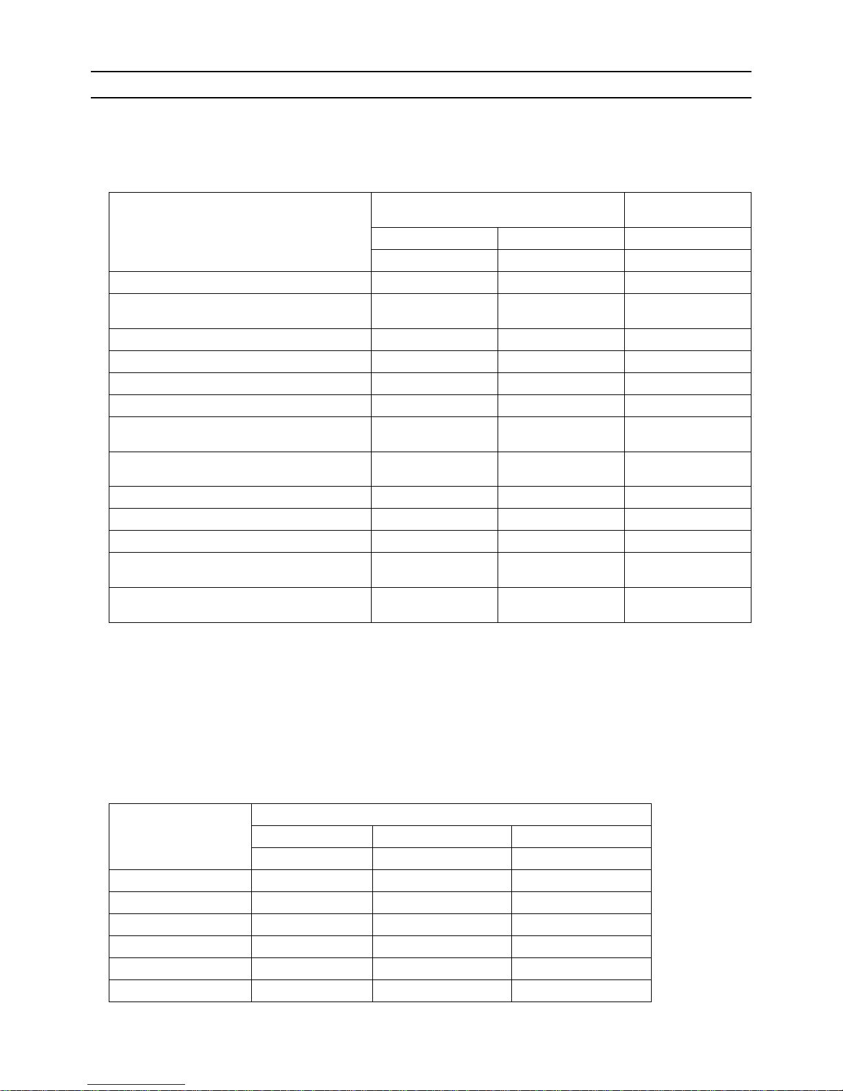
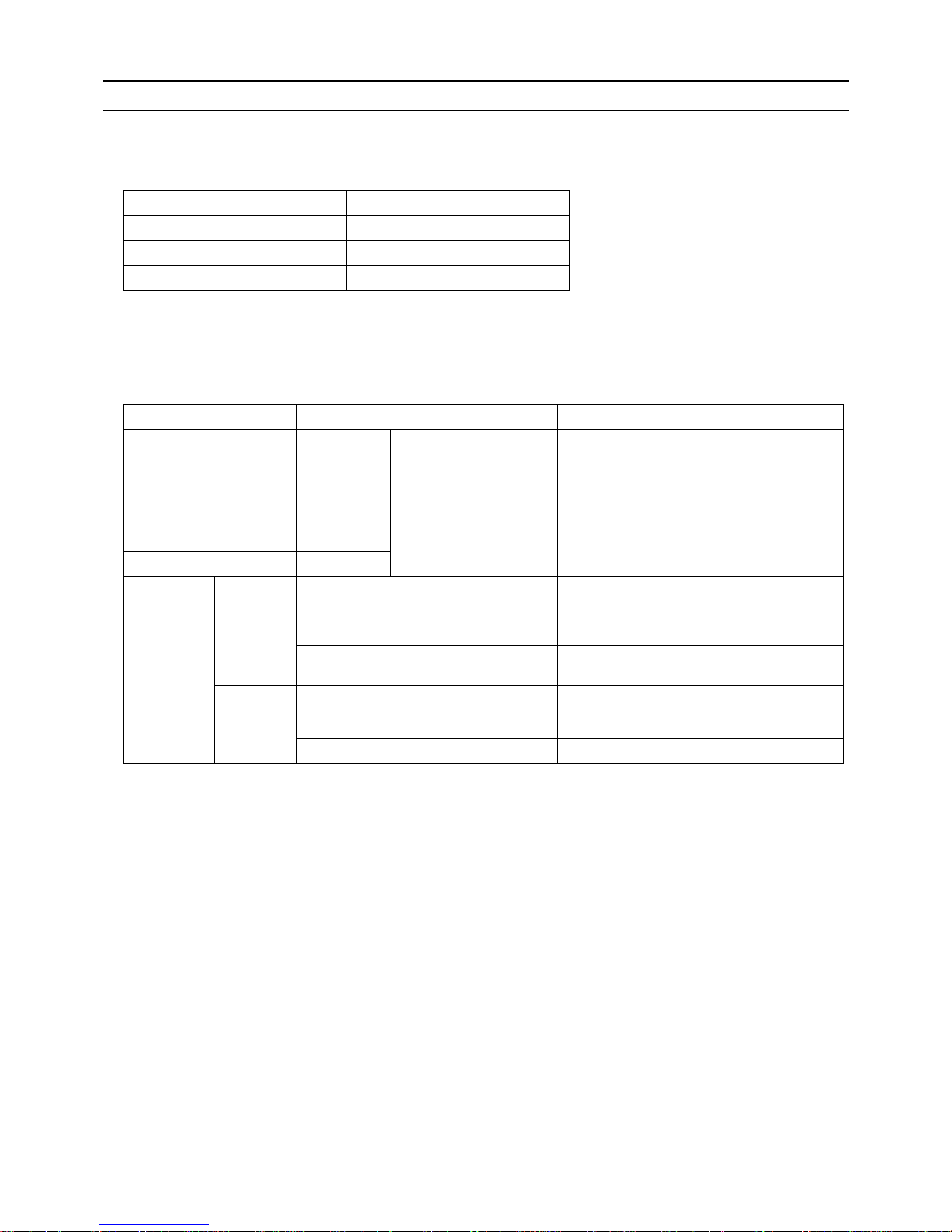
Maximum working pressure Refrigerant type
3.45 MPa [500psi] R22, R407C etc.
4.30 MPa [624psi] R410A etc.
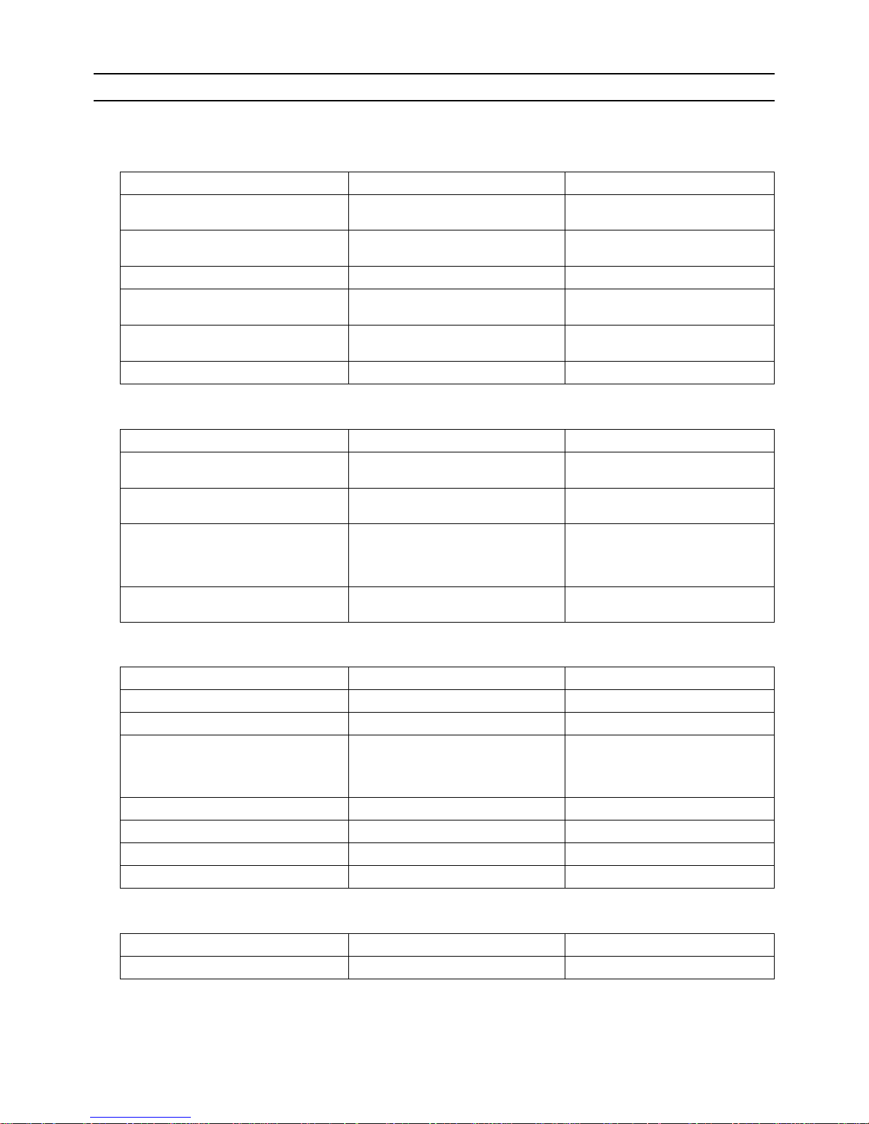
Pipe size (mm[in]) Radial thickness (mm) Type
ø6.35 [1/4"] 0.8t
O-material (Annealed)
ø9.52 [3/8"] 0.8t
ø12.7 [1/2"] 0.8t
ø15.88 [5/8"] 1.0t
ø19.05 [3/4"] 1.0t
1/2H-material,
H-material (Drawn)
ø22.2 [7/8"] 1.0t
ø25.4 [1"] 1.0t
ø28.58 [1-1/8"] 1.0t
ø31.75 [1-1/4"] 1.1t
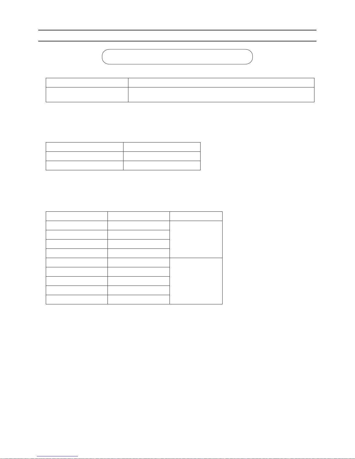
Do not use the existing piping!
Page 15
[ I Read Before Servicing ]
- 6 -
HWE1018A GB
4. Thickness and refrigerant type indicated on the piping materials
Ask the pipe manufacturer for the symbols indicated on the piping material for new refrigerant.
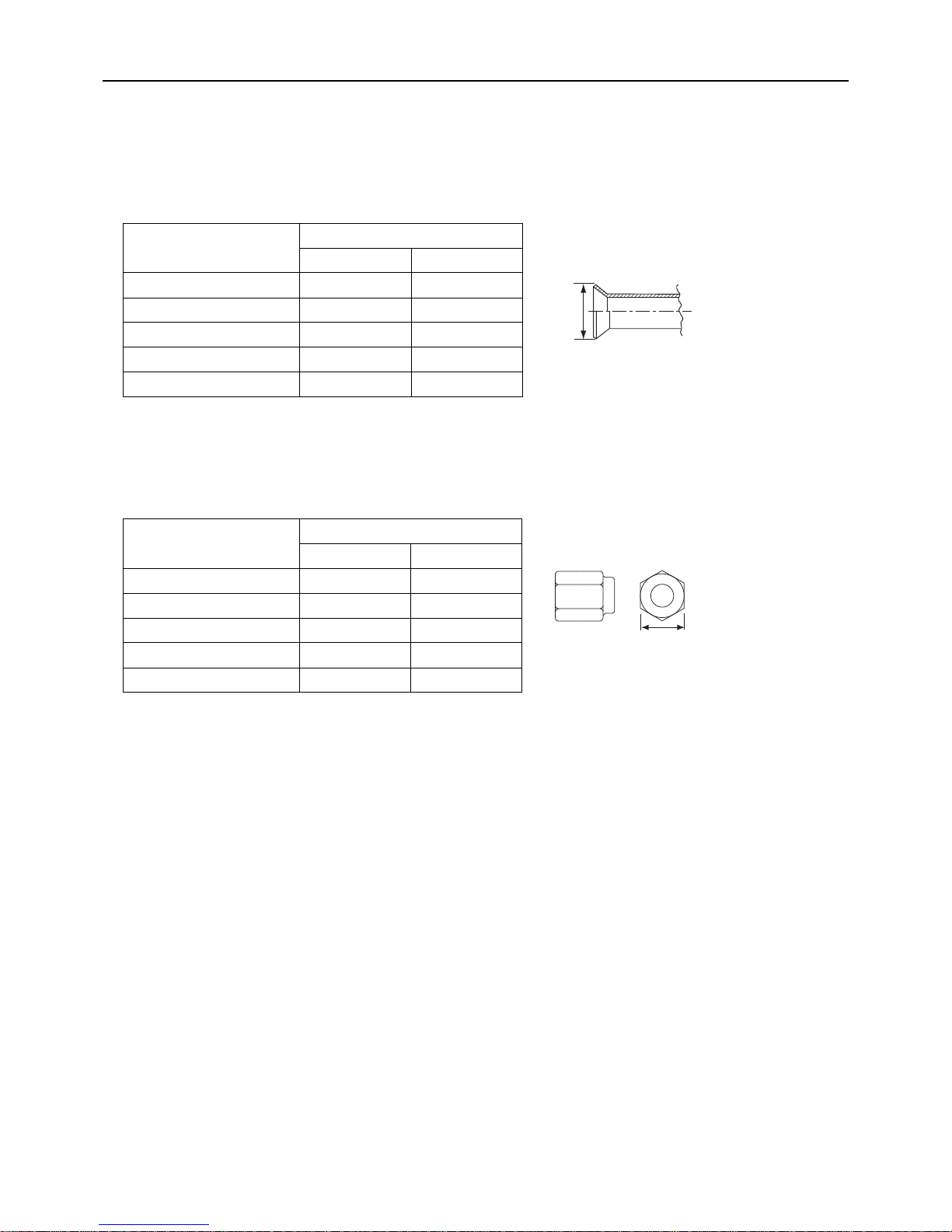
5. Flare processing (O-material (Annealed) and OL-material only)
The flare processing dimensions for the pipes that are used in the R410A system are larger than those in the R22 system.
If a clutch-type flare tool is used to flare the pipes in the system using R410A, the length of the pipes must be between 1.0
and 1.5 mm. For margin adjustment, a copper pipe gauge is necessary.
6. Flare nut
The flare nut type has been changed to increase the strength. The size of some of the flare nuts have also been changed.
The figures in the radial thickness column are based on the Japanese standards and provided only as a reference. Use pipes
that meet the local standards.
Flare processing dimensions (mm[in])
Pipe size (mm[in])
A dimension (mm)
R410A R22, R407C
ø6.35 [1/4"] 9.1 9.0
ø9.52 [3/8"] 13.2 13.0
ø12.7 [1/2"] 16.6 16.2
ø15.88 [5/8"] 19.7 19.4
ø19.05 [3/4"] 24.0 23.3
Flare nut dimensions (mm[in])
Pipe size (mm[in])
B dimension (mm)
R410A R22, R407C
ø6.35 [1/4"] 17.0 17.0
ø9.52 [3/8"] 22.0 22.0
ø12.7 [1/2"] 26.0 24.0
ø15.88 [5/8"] 29.0 27.0
ø19.05 [3/4"] 36.0 36.0
Dimension A
Dimension B
Page 16
[ I Read Before Servicing ]
- 7 -
HWE1018A GB
[4] Storage of Piping
1. Storage location
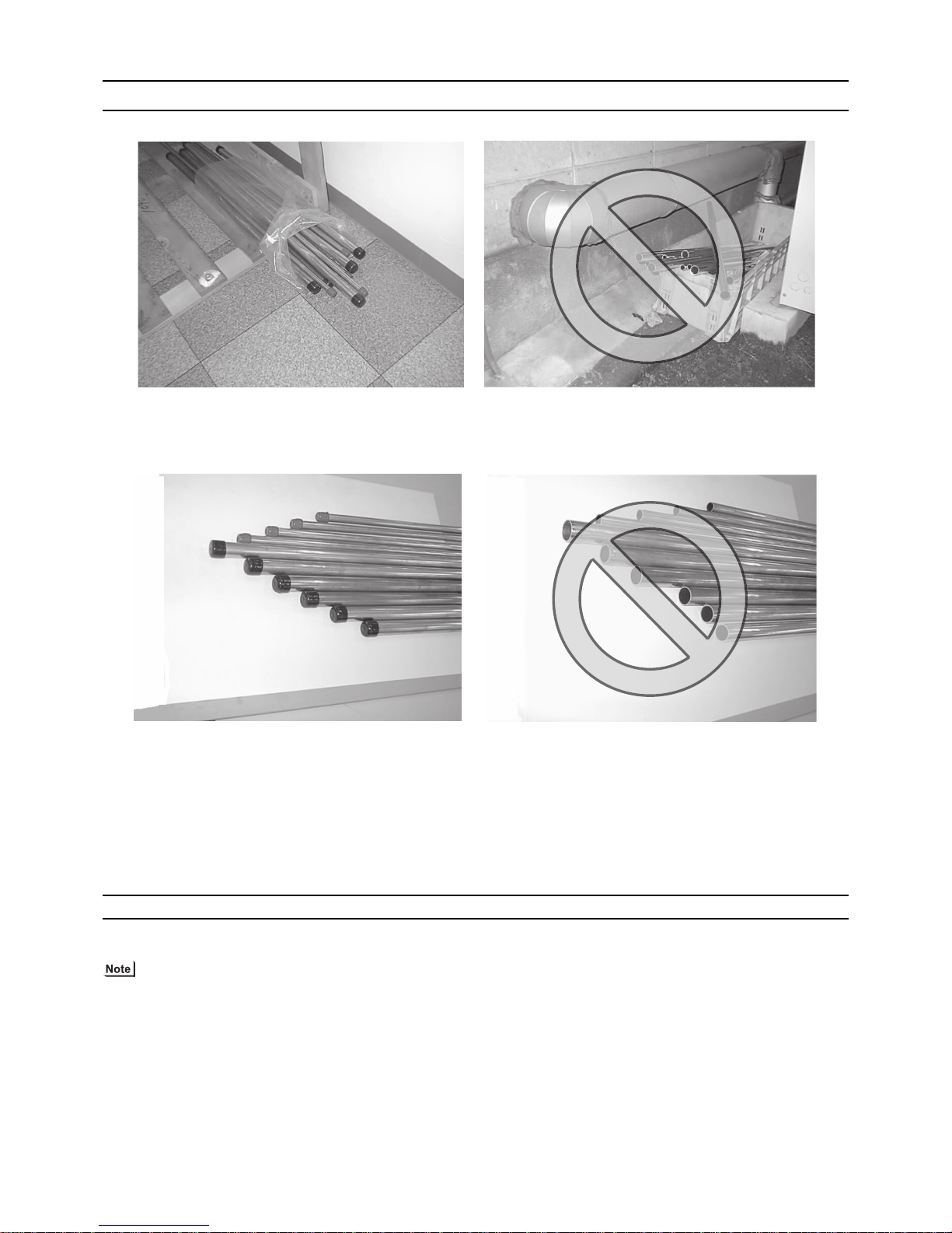
Store the pipes to be used indoors. (Warehouse at site or owner's warehouse)
If they are left outdoors, dust, dirt, or moisture may infiltrate and contaminate the pipe.
2. Sealing the pipe ends
Both ends of the pipes should be sealed until just before brazing.
Keep elbow pipes and T-joints in plastic bags.
The new refrigerator oil is 10 times as hygroscopic as the conventional refrigerating machine oil (such as Suniso) and, if not
handled with care, could easily introduce moisture into the system. Keep moisture out of the pipes, for it will cause the oil to
deteriorate and cause a compressor failure.
[5] Pipe Processing
Use a small amount of ester oil, ether oil, or alkylbenzene to coat flares and flanges.
Use a minimum amount of oil.
Use only ester oil, ether oil, and alkylbenzene.
Page 17
[ I Read Before Servicing ]
- 8 -
HWE1018A GB
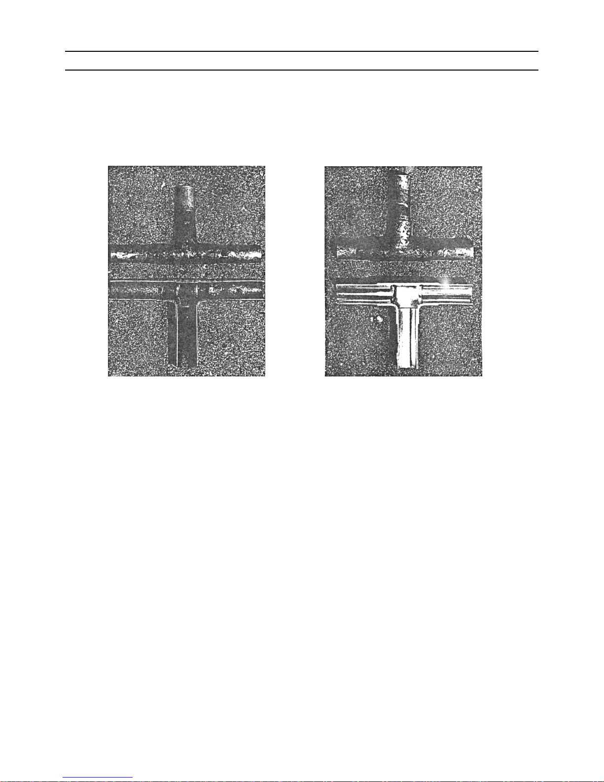
[6] Brazing
No changes have been made in the brazing procedures. Perform brazing with special care to keep foreign objects (such as oxide
scale, water, and dust) out of the refrigerant system.
Example: Inside the brazed connection
1. Items to be strictly observed
Do not conduct refrigerant piping work outdoors if raining.
Use non-oxidized solder.
Use a brazing material (BCuP-3) that requires no flux when brazing between copper pipes or between a copper pipe and
copper coupling.
If installed refrigerant pipes are not immediately connected to the equipment, then braze and seal both ends.
2. Reasons
The new refrigerating machine oil is 10 times as hygroscopic as the conventional oil and is more likely to cause unit failure if
water infiltrates into the system.
Flux generally contains chloride. Residual flux in the refrigerant circuit will cause sludge to form.
3. Notes
Do not use commercially available antioxidants because they may cause the pipes to corrode or refrigerating machine oil to
deteriorate.
Use of oxidized solder for brazing Use of non-oxidized solder for brazing
Page 18
[ I Read Before Servicing ]
- 9 -
HWE1018A GB
[7] Air Tightness Test
No changes have been made in the detection method. Note that a refrigerant leak detector for R22 will not detect an R410A leak.
1. Items to be strictly observed
Pressurize the equipment with nitrogen up to the design pressure (4.15MPa[601psi]), and then judge the equipment's air tight-
ness, taking temperature variations into account.
Refrigerant R410A must be charged in its liquid state (vs. gaseous state).
2. Reasons
Oxygen, if used for an air tightness test, poses a risk of explosion. (Only use nitrogen to check air tightness.)
Refrigerant R410A must be charged in its liquid state. If gaseous refrigerant in the cylinder is drawn out first, the composition
of the remaining refrigerant in the cylinder will change and become unsuitable for use.
3. Notes
Procure a leak detector that is specifically designed to detect an HFC leak. A leak detector for R22 will not detect an
HFC(R410A) leak.
Halide torch R22 leakage detector
Page 19
[ I Read Before Servicing ]
- 10 -
HWE1018A GB
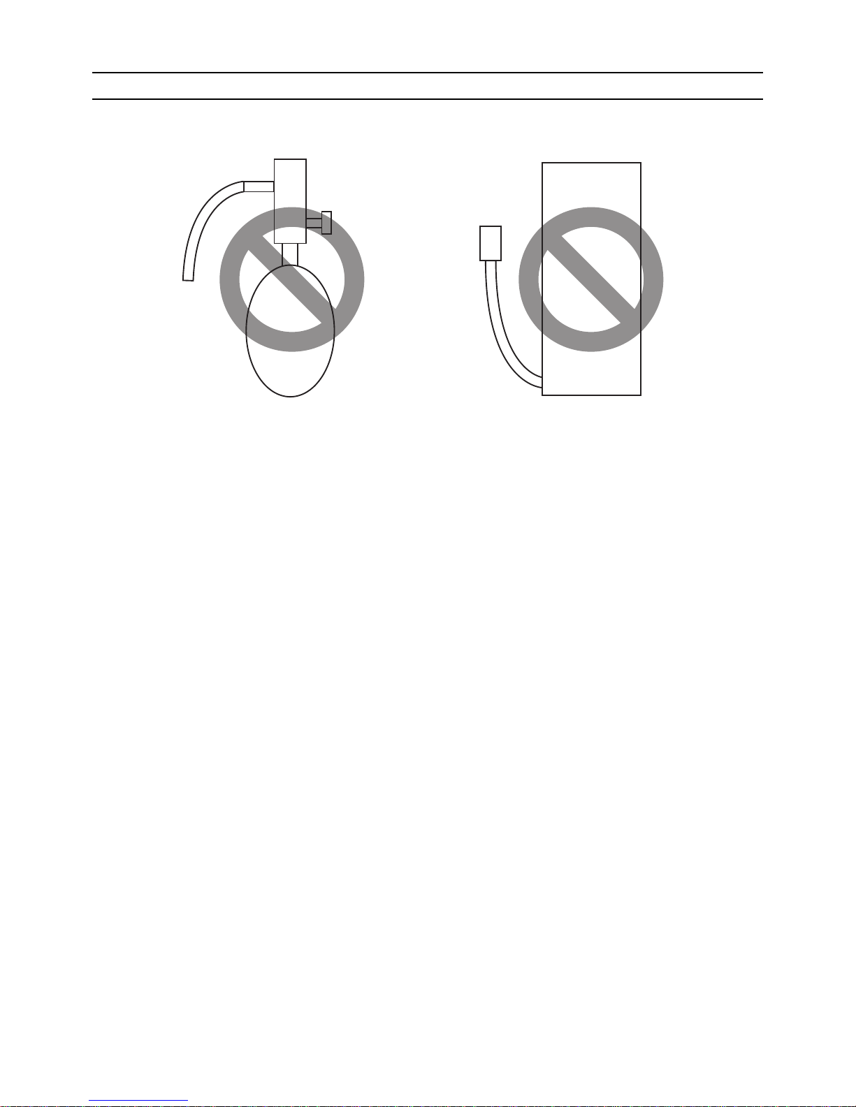
[8] Vacuum Drying (Evacuation)
1. Vacuum pump with a reverse-flow check valve (Photo1)
To prevent the vacuum pump oil from flowing into the refrigerant circuit during power OFF or power failure, use a vacuum
pump with a reverse-flow check valve.
A reverse-flow check valve may also be added to the vacuum pump currently in use.
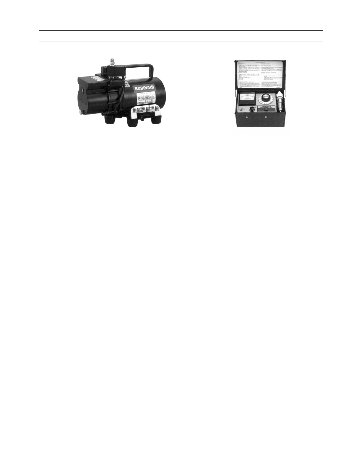
2. Standard of vacuum degree (Photo 2)
Use a vacuum pump that attains 0.5Torr(65Pa) or lower degree of vacuum after 5 minutes of operation, and connect it directly
to the vacuum gauge. Use a pump well-maintained with an appropriate lubricant. A poorly maintained vacuum pump may not
be able to attain the desired degree of vacuum.
3. Required precision of vacuum gauge
Use a vacuum gauge that registers a vacuum degree of 5Torr(650Pa) and measures at intervals of 1Torr(130Pa). (A recommended vacuum gauge is shown in Photo2.)
Do not use a commonly used gauge manifold because it cannot register a vacuum degree of 5Torr(650Pa).
4. Evacuation time
After the degree of vacuum has reached 5Torr(650Pa), evacuate for an additional 1 hour. (A thorough vacuum drying re-
moves moisture in the pipes.)
Verify that the vacuum degree has not risen by more than 1Torr(130Pa) 1hour after evacuation. A rise by less than
1Torr(130Pa) is acceptable.
If the vacuum is lost by more than 1Torr(130Pa), conduct evacuation, following the instructions in section 6. Special vacuum
drying.
5. Procedures for stopping vacuum pump
To prevent the reverse flow of vacuum pump oil, open the relief valve on the vacuum pump side, or draw in air by loosening
the charge hose, and then stop the operation.
The same procedures should be followed when stopping a vacuum pump with a reverse-flow check valve.
6. Special vacuum drying
When 5Torr(650Pa) or lower degree of vacuum cannot be attained after 3 hours of evacuation, it is likely that water has pen-
etrated the system or that there is a leak.
If water infiltrates the system, break the vacuum with nitrogen. Pressurize the system with nitrogen gas to
0.5kgf/cm
2
G(0.05MPa) and evacuate again. Repeat this cycle of pressurizing and evacuation either until the degree of vac-
uum below 5Torr(650Pa) is attained or until the pressure stops rising.
Only use nitrogen gas for vacuum breaking. (The use of oxygen may result in an explosion.)
(Photo1) 15010H (Photo2) 14010
Recommended vacuum gauge:
ROBINAIR 14010 Thermistor Vacuum Gauge
Page 20
[ I Read Before Servicing ]
- 11 -
HWE1018A GB
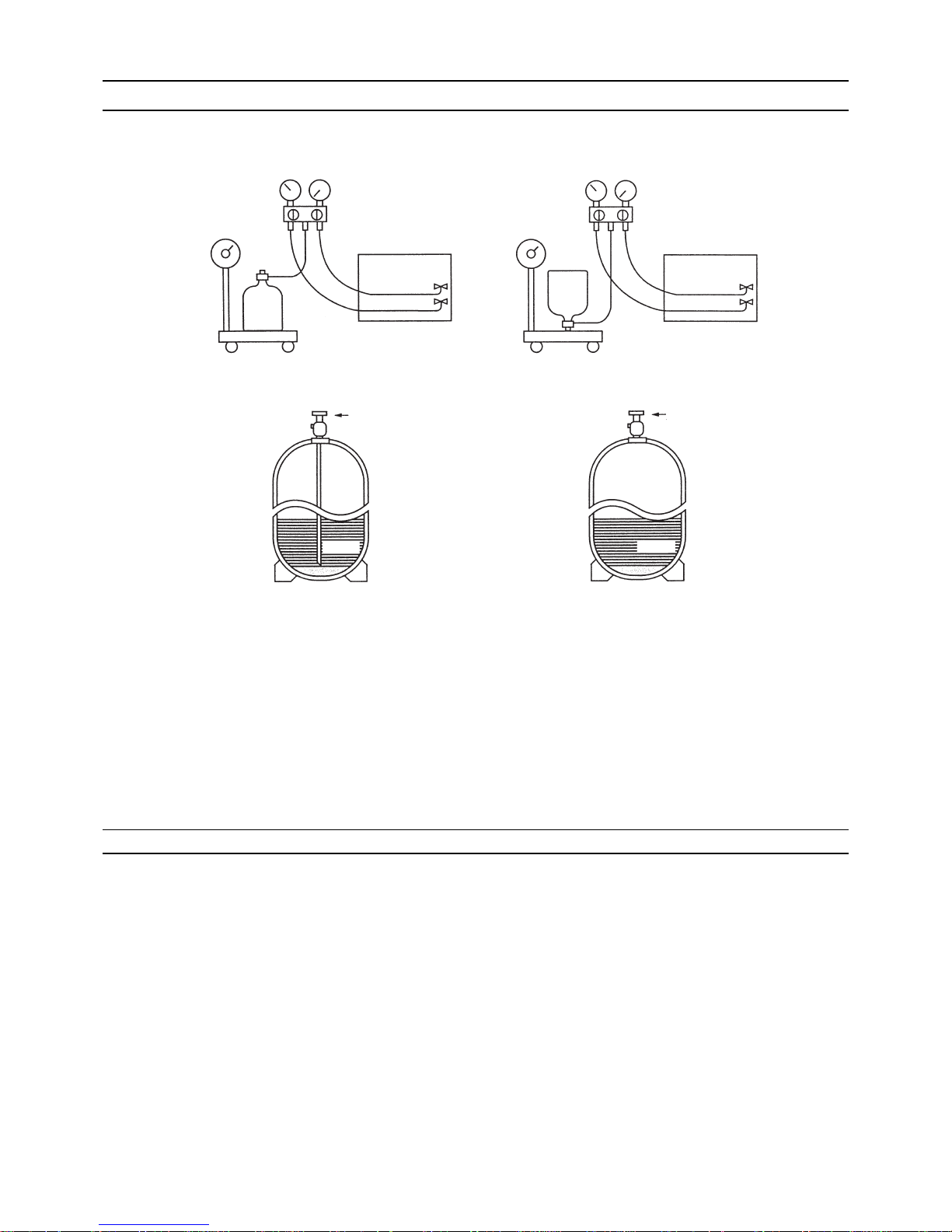
[9] Refrigerant Charging
1. Reasons
R410A is a pseudo-azeotropic HFC blend (boiling point R32=-52°C[-62°F], R125=-49°C[-52°F]) and can almost be handled
the same way as a single refrigerant, such as R22. To be safe, however, draw out the refrigerant from the cylinder in the liquid
phase. If the refrigerant in the gaseous phase is drawn out, the composition of the remaining refrigerant will change and become unsuitable for use.
2. Notes
When using a cylinder with a siphon, refrigerant is charged in the liquid state without the need for turning it upside down. Check
the type of the cylinder on the label before use.
[10] Remedies to be taken in case of a Refrigerant Leak
If the refrigerant leaks out, it may be replenished. The entire refrigerant does not need to be replaced. (Charge refrigerant in the
liquid state.)
Refer to "IX [5] Refrigerant Leak."(page 200)
Cylinder with a siphon
Cylinder color R410A is pink. Refrigerant charging in the liquid state
Cylinder
liquid
Valve Valve
liquid
Cylinder
Cylinder without a siphon
Page 21
[ I Read Before Servicing ]
- 12 -
HWE1018A GB
[11] Characteristics of the Conventional and the New Refrigerants
1. Chemical property
As with R22, the new refrigerant (R410A) is low in toxicity and chemically stable nonflammable refrigerant.
However, because the specific gravity of vapor refrigerant is greater than that of air, leaked refrigerant in a closed room will
accumulate at the bottom of the room and may cause hypoxia.
If exposed to an open flame, refrigerant will generate poisonous gases. Do not perform installation or service work in a confined area.
*1 When CFC11 is used as a reference
*2 When CO
2
is used as a reference
2. Refrigerant composition
R410A is a pseudo-azeotropic HFC blend and can almost be handled the same way as a single refrigerant, such as R22. To
be safe, however, draw out the refrigerant from the cylinder in the liquid phase. If the refrigerant in the gaseous phase is drawn
out, the composition of the remaining refrigerant will change and become unsuitable for use.
If the refrigerant leaks out, it may be replenished. The entire refrigerant does not need to be replaced.
3. Pressure characteristics
The pressure in the system using R410A is 1.6 times as great as that in the system using R22.
New Refrigerant (HFC type) Conventional Refriger-
ant (HCFC type)
R410A R407C R22
R32/R125 R32/R125/R134a R22
Composition (wt%) (50/50) (23/25/52) (100)
Type of Refrigerant Pseudo-azeotropic
Refrigerant
Non-azeotropic
Refrigerant
Single Refrigerant
Chloride Not included Not included Included
Safety Class A1/A1 A1/A1 A1
Molecular Weight 72.6 86.2 86.5
Boiling Point (°C/°F) -51.4/-60.5 -43.6/-46.4 -40.8/-41.4
Steam Pressure
(25°C,MPa/77°F,psi) (gauge)
1.557/226 0.9177/133 0.94/136
Saturated Steam Density
(25°C,kg/m
3
/77°F,psi)
64.0 42.5 44.4
Flammability Nonflammable Nonflammable Nonflammable
Ozone Depletion Coefficient (ODP)
*1
0 0 0.055
Global Warming Coefficient (GWP)
*2
1730 1530 1700
Refrigerant Charging Method Refrigerant charging in
the liquid state
Refrigerant charging in
the liquid state
Refrigerant charging in
the gaseous state
Replenishment of Refrigerant after a Refrigerant
Leak
Available Available Available
Temperature (°C/°F)
Pressure (gauge)
R410A R407C R22
MPa/psi MPa/psi MPa/psi
-20/-4 0.30/44 0.18/26 0.14/20
0/32 0.70/102 0.47/68 0.40/58
20/68 1.34/194 0.94/136 0.81/117
40/104 2.31/335 1.44/209 1.44/209
60/140 3.73/541 2.44/354 2.33/338
65/149 4.17/605 2.75/399 2.60/377
Page 22
[ I Read Before Servicing ]
- 13 -
HWE1018A GB
[12] Notes on Refrigerating Machine Oil
1. Refrigerating machine oil in the HFC refrigerant system
HFC type refrigerants use a refrigerating machine oil different from that used in the R22 system.
Note that the ester oil used in the system has properties that are different from commercially available ester oil.
2. Effects of contaminants
*1
Refrigerating machine oil used in the HFC system must be handled with special care to keep contaminants out.
The table below shows the effect of contaminants in the refrigerating machine oil on the refrigeration cycle.
3. The effects of contaminants in the refrigerating machine oil on the refrigeration cycle.
Refrigerant Refrigerating machine oil
R22 Mineral oil
R407C Ester oil
R410A Ester oil
*1. Contaminants is defined as moisture, air, processing oil, dust/dirt, wrong types of refrigerant, and refrigerating machine oil.
Cause Symptoms Effects on the refrigerant cycle
Water infiltration Frozen expansion valve
and capillary tubes
Clogged expansion valve and capillary tubes
Poor cooling performance
Compressor overheat
Motor insulation failure
Burnt motor
Coppering of the orbiting scroll
Lock
Burn-in on the orbiting scroll
Hydrolysis
Sludge formation and adhesion
Acid generation
Oxidization
Oil degradation
Air infiltration Oxidization
Infiltration of
contaminants
Dust, dirt
Adhesion to expansion valve and capillary
tubes
Clogged expansion valve, capillary tubes, and
drier
Poor cooling performance
Compressor overheat
Infiltration of contaminants into the compressor
Burn-in on the orbiting scroll
Mineral oil
etc.
Sludge formation and adhesion Clogged expansion valve and capillary tubes
Poor cooling performance
Compressor overheat
Oil degradation Burn-in on the orbiting scroll
Page 23

[ I Read Before Servicing ]
- 14 -
HWE1018A GB
Page 24

- 15 -
HWE1018A GB
II Restrictions
[1] System configuration ....................................................................................................... 17
[2] Types and Maximum allowable Length of Cables ........................................................... 18
[3] Switch Settings and Address Settings ............................................................................. 20
[4] An Example of a System to which an MA Remote Controller is connected..................... 24
[5] Restrictions on Pipe Length ............................................................................................. 32
Page 25

- 16 -
HWE1018A GB
Page 26

[ II Restrictions ]
- 17 -
HWE1018A GB
II Restrictions
[1] System configuration
*1 When two outdoor units are connected to one indoor unit, two refrigerant circuits must be connected.
Only one refrigerant circuit can be connected to the indoor unit at factory shipment. To connect two refrigerant circuits, perform some work on the unit.
1. Restrictions when the PFD-type indoor units are connected (related to the system)
(1) The PFD-type indoor units cannot be connected to the ME remote controller.
(2) The address settings must be made on this system.
(3) The following functions cannot be selected on the PFD-type indoor units.
1) Switching between automatic power recovery Enabled/Disabled (Fixed to "Enabled" in the PFD-type indoor units)
2) Switching between power source start/stop (Fixed to "Disabled" in the PFD-type indoor units)
(4) The PFD-type indoor units and other types of indoor units cannot be grouped.
(5) The following functions are limited when the system controller (such as G-50A) is connected.
1) To perform group operation in the system with two refrigerant circuits (combination of two outdoor units and one indoor unit:
P500 model only), the addresses of the controller boards No.1 and No.2 on a indoor unit must be set within a group.
2) The local operation cannot be prohibited with the main remote controller.
3) When the switches of the PFD-type indoor units are set as follows, the unit ON/OFF operation cannot be made with the main
remote controller.
When the Normal/Local switching switch is set to "Local"
When the DipSW1-10 on the controller circuit board is set to "ON"
Indoor unit model Outdoor unit model
PFD-P250VM-E PUHY-P250YJM-A
PFD-P500VM-E PUHY-P250YJM-A x 2 *1
Page 27
[ II Restrictions ]
- 18 -
HWE1018A GB
[2] Types and Maximum allowable Length of Cables
1. Wiring work
(1) Notes
1) Have all electrical work performed by an authorized electrician according to the local regulations and instructions in this manual.
2) Install external transmission cables at least 5cm [1-31/32"] away from the power supply cable to avoid noise interference.
(Do not put the control cable and power supply cable in the same conduit tube.)
3) Provide grounding for the outdoor unit as required.
4) Run the cable from the electric box of the indoor or outdoor unit in such way that the box is accessible for servicing.
5) Do not connect power supply wiring to the terminal block for transmission line. Doing so will damage the electronic components on the terminal block.
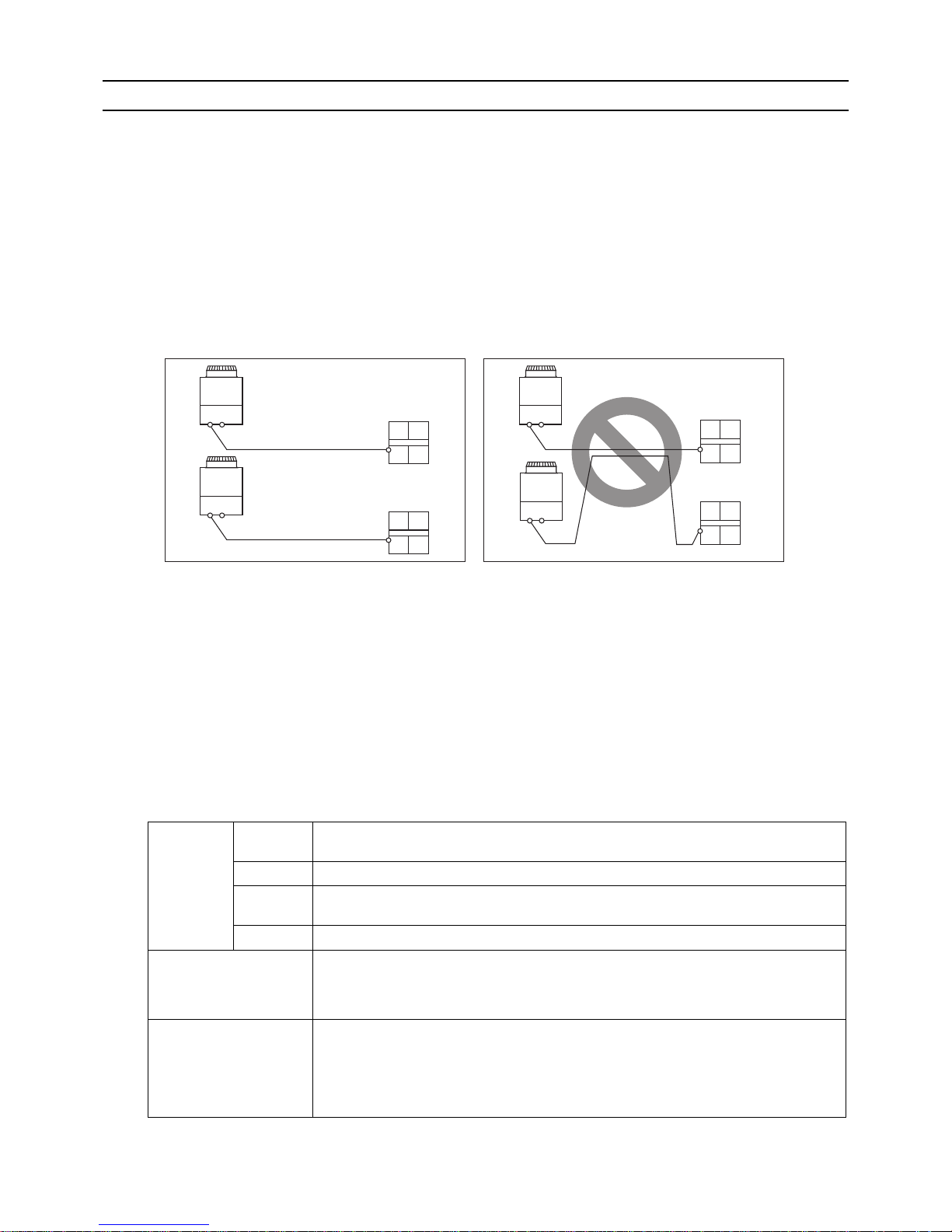
6) Use 2-core shielded cables as transmission cables.
Use a separate 2-core control cable for each refrigerant system. Do not use a single multiple-core cable to connect indoor
units that belong to different refrigerant systems. The use of a multiple-core cable may result in signal transmission errors and
malfunctions.
(2) Control wiring
Different types of control wiring are used for different systems.
Refer to section "[4] An Example of a System to which an MA Remote Controller is connected" before performing wiring work.
Types and maximum allowable length of cables
Control lines are categorized into 2 types: transmission line and remote controller line.
Use the appropriate type of cables and observe the maximum allowable length specified for a given system. If a given system
has a long transmission line or if a noise source is located near the unit, place the unit away from the noise source to reduce
noise interference.
1) M-NET transmission line
Cable type
Facility
type
All facility types
Type Shielded cable CVVS, CPEVS, MVVS
Number of
cores
2-core cable
Cable size Larger than 1.25mm
2
[AWG16]
Maximum transmission
line distance between the
outdoor unit and the farthest indoor unit
200m [656ft] max.
Maximum transmission
line distance for centralized control and Indoor/
outdoor transmission line
(Maximum line distance
via outdoor unit)
500m [1640ft] max.
*The maximum overall line length from the power supply unit on the transmission lines for
centralized control to each outdoor unit or to the system controller is 200m [656ft] max.
TB3:Terminal block for transmission line connection
TB7:Terminal block for transmission line for centralized control
multiple-core cable
2-core shielded cable
2-core shielded cable
Indoor unit
Indoor unit
Indoor unit
Indoor unit
Outdoor unit
Outdoor unit
Outdoor unit
TB3
TB7
TB3
TB7
TB3
TB7
TB3
TB7
Page 28

[ II Restrictions ]
- 19 -
HWE1018A GB
2) Remote controller wiring
*1 The use of cables that are smaller than 0.75mm
2
[AWG18] is recommended for easy handling.
MA remote controller
Cable type
Type CVV
Number of
cores
2-core cable
Cable size
0.3 to 1.25mm
2 *1
[AWG22 to 16]
Maximum overall line
length
200m [656ft] max.
Page 29
[ II Restrictions ]
- 20 -
HWE1018A GB
[3] Switch Settings and Address Settings
1. Switch setting
Refer to section "[4] An Example of a System to which an MA Remote Controller is connected" before performing wiring work.
Set the switches while the power is turned off.
If the switch settings are changed while the unit is being powered, those changes will not take effect, and the unit will not
function properly.
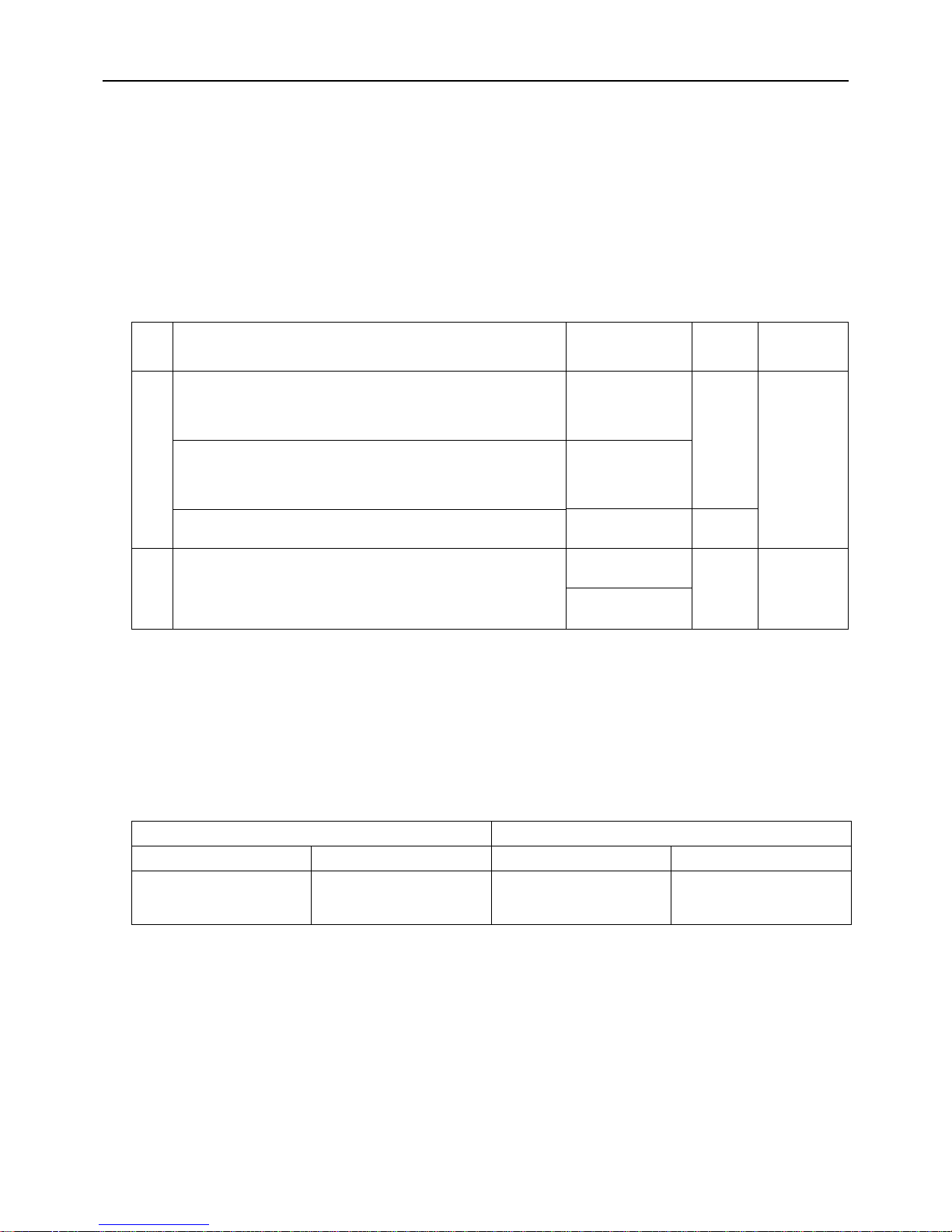
2. Address settings
(1) Address settings table
The need for address settings and the range of address setting depend on the configuration of the system. Refer to section
"II [4] An Example of a System to which an MA Remote Controller is connected"
*1. If a given address overlaps any of the addresses that are assigned to indoor or outdoor units in other refrigerant systems,
use a different, unused address within the setting range.
(2) Power supply switch connector connection on the outdoor unit
(Factory setting: The male power supply switch connector is connected to CN41.)
Unit or controller Symbols Address setting
range
Setting method Ad-
dress
setting
Indoor
unit
Main/sub
unit
IC 01 to 50
*1
In case of 10HP system, assign an odd number starting with
"01". In case of 20HP system with two refrigerant circuits, assign a sequential odd number starting with "01" to the upper
indoor controller, and assign "the address of the upper indoor
controller + 1" to the lower indoor controller.
00
MA remote
controller
MA No address settings required. (The main/sub switch must be configured if two
remote controllers are connected to the system or if the indoor units are connected to different outdoor units.)
Main
Outdoor unit OC 51 to 100
*1
Assign an address of the indoor units in the same refrigerant system and 50.
00
System configuration
Connection to the
system controller
Power supply unit for
transmission lines
Group operation of
units in a system with
multiple outdoor units
Power supply switch connector connection
System with one
outdoor unit
_ _ _ Leave CN41 as it is
(Factory setting)
System with multiple outdoor units
Not connected _ Not grouped
Grouped Disconnect the male con-
nector from the female
power supply switch connector (CN41) and connect it to the female power
supply switch connector
(CN40) on only one of the
outdoor units.
*Connect the S (shielded)
terminal on the terminal
block (TB7) on the outdoor unit whose CN41
was replaced with CN40
to the ground terminal
( ) on the electric box.
With connection to
the indoor-outdoor
transmission line
Not required Grouped/not grouped
With connection to
the centralized control system
Not required
(Powered from the
outdoor unit)
Grouped/not grouped
Required Grouped/not grouped Leave CN41 as it is
(Factory setting)
Page 30
[ II Restrictions ]
- 21 -
HWE1018A GB
(3) Settings of MA remote controller Main/Sub switching switch (When MA remote controller is used: factory setting
"Main")
Main/sub settings are available on the MA remote controller. When two remote controllers are connected, set either of them
to "Sub".
(4) Selecting the position of temperature detection for the indoor unit (Factory setting: SWC "Standard")
To use a suction temperature sensor, set SWC to "Option". (The suction temperature sensor is supplied as standard specification.)
(5) Connection of two refrigerant circuits
When two refrigerant circuits are connected on site, make the switch settings on the controller circuit board following the instructions described in the installation manual for the indoor unit.
(6) Cooling-only setting for the indoor unit: Cooling only model (Factory setting: SW3-1 on the indoor unit to "OFF.")
When using indoor unit as a cooling-only unit, set SW3-1 on the indoor unit to ON.
(7) Various types of control using input-output signal connector on the outdoor unit (various connection options)
*4. By setting Dip SW5-5, the Low-noise mode can be switched between the Capacity priority mode and the Low-noise pri-
ority mode.
When SW5-5 is set to ON: The Low-noise mode always remains effective.
When SW5-5 is set to OFF: The Low-noise mode is cancelled when certain outside temperature or pressure criteria are
met, and the unit goes into normal operation (capacity priority mode).
*5. When multiple outdoor units exist in one refrigerant circuit system, settings on every outdoor unit (signal input) are re-
quired.
*6. Take out signals from the outdoor unit (OC) if multiple outdoor units exist in a single system.
Type Usage Function
Terminal
to be
used
*1
*1. For detailed drawing, refer to "Example of wiring connection".
Option
Input Prohibiting cooling/heating operation (thermo OFF) by an external
input to the outdoor unit.
*It can be used as the DEMAND control device for each refriger-
ant system.
DEMAND (level) CN3D
*2
*2. For details, refer to 1) through 2) shown below.
Adapter for
external input
(PACSC36NA-E)
Performs a low level noise operation of the outdoor unit by an external input to the outdoor unit.
* It can be used as the silent operation device for each refrigerant
system.
Low-noise mode
(level)
*3*4
*3. Low-noise mode is valid when Dip SW4-4 on the outdoor unit is set to OFF. When DIP SW4-4 is set to ON, 4 levels of
on-DEMAND are possible, using different configurations of low-noise mode input and DEMAND input settings. When 2
or more outdoor units exist in one refrigerant circuit system, 8 levels of on-DEMAND are possible.
Forces the outdoor unit to perform a fan operation by receiving signals from the snow sensor.
*5
Snow sensor signal
input (level)
CN3S
Out-
put
How to extract signals from the outdoor unit
*It can be used as an operation status display device.
*It can be used for an interlock operation with external devices.
Operation status of
the compressor
*5
CN51 Adapter for
external output
(PACSC37SA-E)
Error status
*6
Low-noise mode is effective Capacity priority mode becomes effective
Cooling Heating Cooling Heating
TH7 < 30°C [86°F]
and
63HS1 < 32kg/cm
2
TH7 > 3°C [37°F]
and
63LS > 4.6kg/cm
2
TH7 > 35°C [95°F]
or
63HS1 > 35kg/cm
2
TH7 < 0°C [32°F]
or
63LS < 3.9kg/cm
2
Page 31

[ II Restrictions ]
- 22 -
HWE1018A GB
CAUTION
1) Wiring should be covered by insulation tube with supplementary insulation.
2) Use relays or switches with IEC or equivalent standard.
3) The electric strength between accessible parts and control circuit should have 2750V or more.
Example of wiring connection
3. Demand control
(1) General outline of control
Demand control is performed by using the external signal input to the 1-2 and 1-3 pins of CN3D on the outdoor units (OC and
OS).
Between 2 and 8 steps of demand control is possible by setting DIP SW4-4 on the outdoor units (OC and OS).
*1. Available demand functions
P250YJM model (single-outdoor-unit system): 2 and 4 steps shown in the rows (a) and (b) in the table above only.
P500YSJM model (two-outdoor-unit system OC+OS): 2-8 steps shown in the rows (a), (b), (c), and (d) in the table above.
*2. External signal is input to CN3D on the outdoor unit whose SW4-4 is set to ON. When SW4-4 is set to OFF on all outdoor
units, the signal is input to the CN3D on the OC.
Outdoor units whose SW4-4 is set to ON are selectable in a single refrigerant system.
Table.1
No Demand control switch
DipSW4-4
Input to CN3D *2
OC OS
(a) 2 steps(0-100%) OFF OFF OC
(b) 4 steps(0-50-75-100%) ON OFF OC
(c) OFF ON OS
(d) 8 steps(0-25-38-50-63-75-88-100%) ON ON OC and OS
CN51
CN3S
CN51
X
Y
L
1
L
2
ecruos rewop pmaL
Distant control
board
Relay circuit Adapter
1
Outdoor unit
control board
Preparations
in the field
Maximum cable
length is 10m
5
4
3
X
Y
L1 : Outdoor unit error display lamp
L2 : Compressor operation lamp (compressor running state)
X, Y : Relay (coil =<0.9W : DC12V)
1. Optional part : PAC-SC37SA-E or field supply.
2. Optional part : PAC-SC36NA-E or field supply.
X : Relay
Snow sensor : The outdoor fan runs when X is closed
in stop mode or thermostat mode.
X
CN3S
Preparations
in the field
Maximum cable
length is 10m
Adapter
2
Outdoor unit
control board
2
3
1
Contact rating voltage >= DC15V
Contact rating current >= 0.1A
Minimum applicable load =< 1mA at DC
Relay circuit
CN3D
2. Optional part : PAC-SC36NA-E or field supply.
X : Low-noise mode
X : Low-noise mode
Y : Compressor ON/OFF
X,Y : Relay
Contact rating voltage >= DC15V
Contact rating current >= 0.1A
Minimum appicable load =< 1mA at DC
Y
X
CN3D
Preparations
in the field
Maximum cable
length is 10m
Adapter
2
Outdoor unit
control board
3
2
1
Relay circuit
2. Optional part : PAC-SC36NA-E or field supply.
X
CN3D
Preparations
in the field
Maximum cable
length is 10m
Adapter
2
Outdoor unit
control board
2
3
1
X : Relay
fan frequency and maximum compressor frequency.
Contact rating voltage >= DC15V
Contact rating current >= 0.1A
Minimum applicable load =< 1mA at DC
Low-noise mode : The noise level is reduced by controlling the maximum
Relay circuit
Page 32

[ II Restrictions ]
- 23 -
HWE1018A GB
*3. If wrong sequence of steps are taken, the units may go into the Thermo-OFF (compressor stop) mode.
Ex) When switching from 100% to 50%
(Incorrect) 100% to 0% to 50% : The units may go into the Thermo-OFF mode.
(Correct) 100% to 75% to 50%
*4. The percentage of the demand listed in the table above is an approximate value based on the compressor volume and
does not necessarily correspond with the actual capacity.
*5. Notes on using demand control in combination with the low-noise mode
To enable the low-noise mode, it is necessary to short-circuit 1-2 pin of CN3D on the outdoor unit whose SW4-4 is set to
OFF.
When SW4-4 is set to ON on all outdoor units, the following operations cannot be performed.
Performing 4-step demand in combination with the low-noise operation in a single-outdoor-unit system.
Performing 8-step demand in combination with the low-noise operation in a two-outdoor-unit system.
(2) Contact input and control content
1) 2-step demand control
The same control as the Thermo-OFF is performed by closing 1-3 pin of CN3D.
2) 4-step demand control (When SW4-4 is set to ON on an outdoor unit)
Demand capacity is shown below.
3) 8-step demand control (When SW4-4 is set to ON on two outdoor units)
Demand capacity is shown below.
*1. The outdoor units whose SW4-4 is set to ON are designated as No. 1and No. 2 in the order of address from small to large.
Ex) When outdoor units whose SW4-4 is set to ON are designated as OC and OS, OC=No. 1 and OS=No. 2.
CN3D
1-3P
Open x = 100%
Close x = 0%
CN3D 1-2P
1-3P Open Close
Open x = 100% x = 75%
Close x = 0% x = 50%
8-step demand No.2 CN3D
1-2P Open Short-circuit
No.1 CN3D 1-2P 1-3P Open Short-circuit Open Short-circuit
Open Open 100% 50% 88% 75%
Short-circuit 50% 0% 38% 25%
Short-circuit Open 88% 38% 75% 63%
Short-circuit 75% 25% 63% 50%
Page 33

- 24 -
[ II Restrictions ]
GBHWE1018A
[4] An Example of a System to which an MA Remote Controller is connected
1. System with one refrigerant
(1) Sample control wiring
(2) Notes
1) Leave the male connector on the female power supply
switch connector (CN41) on the outdoor unit as it is.
2) It is not necessary to provide grounding to S terminal on
the terminal block for transmission line for centralized
control (TB7).
3) Although two indoor controllers (controller circuit boards)
are equipped inside the P500 models of indoor units, the
board on No.2 side (lower side) is not used. Do not connect wiring to the lower controller circuit board.
(3) Maximum allowable length
1) Indoor/outdoor transmission line
Maximum distance (1.25mm
2
[AWG16] or larger)
L1+L2 200m [656ft]
*Two indoor controllers (controller circuit boards)
are equipped in the indoor unit (P500).
OC
TB3
TB7
M1M2
M1M2
S
51
IC
TB5-1
A1B1S
01
TB5-2
A2 B2
S
02
AB
TB15
1
2
MA
L2L1
Leave the male
connector on
CN41 as it is.
Leave the male
connector on
CN41 as it is.
OS
TB3
TB7
M1M2
M1M2
S
52
Page 34

[ II Restrictions ]
25- 25 -
HWE1018A GB
(4) Wiring method
1) Indoor/outdoor transmission line
Connect M1, M2 terminals of the indoor/outdoor trans-
mission line terminal block (TB3) on the outdoor unit (OC
and OS) and A1, B1 terminals of the indoor/outdoor terminal block (TB5-1) on the indoor unit (IC). (Non-polarized 2-core cable)
Only use shielded cables.
Shielded cable connection
Connect the earth terminal of the OC and S terminal of
the IC terminal block (TB5-1).
2) Switch setting
Address setting is required as follows.
(5) Address setting method
The outdoor units in the same refrigerant circuit are automatically designated as OC and OS.
Units are designated as OC and OS in the descending order of capacity (ascending order of address if the capacities are the
same).
Procedures Unit or controller
Address
setting range
Setting method Notes
Factory
setting
1 Indoor
unit
Main unit IC 01 to 50 Assign a sequential odd number
starting with "01" to the upper indoor controller.
00
Sub unit IC 01 to 50 Assign sequential numbers start-
ing with the address of the main
unit in the same group. (Main
unit address +1)
2 Outdoor unit OC OS51 to 100 Assign sequential numbers to
the outdoor units starting with the
number that equals the address
of the indoor unit in the same refrigerant circuit plus 50.
00
3MA
remote
controller
Main
remote
controller
MA No settings
required.
-Main
Sub
remote
controller
MA Sub
remote
controller
Settings to be made with the sub/
main switch
Page 35

- 26 -
[ II Restrictions ]
GBHWE1018A
2. System with two refrigerant circuits
(1) Sample control wiring
(2) Notes
1) Assign the sequential number to the indoor units.
2) Do not connect the terminal blocks (TB5) on the indoor
unitsthat are connected to different outdoor units with
each other.
3) Replacement of male power supply switch connector(CN41) must be performed only on one of the outdoor
units.
4) Provide grounding to S terminal on the terminal block fortransmission line for centralized control (TB7) on only
one ofthe outdoor units.
5) When the power supply unit is connected to the transmission line for centralized control, leave the male connector on the female power supply switch connector
(CN41) as it is. (Factory setting)
(3) Maximum allowable length
1) Indoor/outdoor transmission line
Maximum distance (1.25mm
2
[AWG16] or larger)
L1, L2 200m [656ft]
2) Transmission line for centralized control
Maximum line distance via outdoor unit.
(1.25mm2 [AWG16] or larger)
L1+L31+L2 500m [1640ft]
OC
TB3
TB7
M1M2
M1M2
S
51
IC
TB5-1
A1 B1
S
01
TB5-2
A2 B2
S
02
OC
TB3
TB7
S
52
AB
TB15
1
2
MA
L31
L1
L2
CN41
CN40
Replace
Connect
M1M2
M1M2
*Two indoor controllers (controller circuit boards)
are equipped in the indoor unit (P500).
Leave the male
connector on
CN41 as it is.
Not connect
Page 36

[ II Restrictions ]
27- 27 -
HWE1018A GB
(4) Wiring method
1) Indoor/outdoor transmission line
Connect M1, M2 terminals of the indoor/outdoor trans-
mission line terminal block (TB3) on the outdoor unit (OC
) and A1, B1 terminals of the indoor/outdoor terminal
block (TB5-1) on the indoor unit (IC). (Non-polarized 2core cable)
Only use shielded cables.
Shielded cable connection
Connect the earth terminal of the OC and S terminal of
the IC terminal block (TB5-1).
2) Transmission line for centralized control
Daisy-chain terminals M1 and M2 on the terminal block
for transmission line for centralized control (TB7) on
each outdoor unit (OC). Disconnect the male connector
on the controller board from the female power supply
switch connector (CN41), and connect it to the female
power supply switch connector (CN40) on only one of the
outdoor units.
Only use shielded cables.
Shielded cable connection
To ground the shielded cable, daisy-chain the S-terminals on the terminal block (TB7) on each of the outdoor
units. Connect the S (shielded) terminal on the terminal
block (TB7) on the outdoor unit whose male connector
on CN41 was disconnected and connected to CN40 to
the earth terminal( ) on the electric box.
3) Switch setting
Address setting is required as follows.
(5) Address setting method
Procedures Unit or controller
Address
setting range
Setting method Notes
Factory
setting
1 Indoor
unit
Main unit IC 01 to 50 Assign a sequential odd number
starting with "01" to the upper indoor controller.
00
Sub unit IC 01 to 50 Assign sequential numbers start-
ing with the address of the main
unit in the same group. (Main
unit address +1)
2 Outdoor unit OC 51 to 100 Add 50 to the address assigned
to the indoor unit connected to
the system with one outdoor unit.
00
3MA
remote
controller
Main
remote
controller
MA No settings
required.
-Main
Sub
remote
controller
MA Sub
remote
controller
Settings to be made with the sub/
main switch
Page 37

- 28 -
[ II Restrictions ]
GBHWE1018A
3. System in which two MA remote controllers are connected to one indoor unit
(1) Sample control wiring
(2) Notes
1) Leave the male connector on the female power supply
switch connector (CN41) on the outdoor unit as it is.
2) It is not necessary to provide grounding to S terminal on
the terminal block for transmission line for centralized
control (TB7).
3) Although two indoor controllers (controller circuit boards)
are equipped inside the P500 models of indoor units, the
board on No.2 side (lower side) is not used. Do not connect wiring to the lower controller circuit board.
4) No more than two MA remote controllers (including both
main and sub controllers) can be connected to a group of
indoor units. If three or more MA remote controllers are
connected, remove the wire for the MA remote controller
from the terminal block (TB15).
(3) Maximum allowable length
1) Indoor/outdoor transmission line
Same as [4] 1.
2) MA remote controller wiring
Maximum overall line length (0.3 to 1.25mm
2
[AWG 22 to
16])
m1+m2 200m [656ft]
*Two indoor controllers (controller circuit boards)
are equipped in the indoor unit (P500).
Leave the male
connector on
CN41 as it is.
OC
TB3
TB7
M1M2
M1M2
S
51
IC
TB5-1
A1B1
S
01
TB5-2
A2 B2
S
02
AB
TB15
1
2
MA(Main)
AB
MA(Sub)
L2L1
Leave the male
connector on
CN41 as it is.
OS
TB3
TB7
M1M2
M1M2
S
52
A1 B2
MA
m1
m2
Page 38

[ II Restrictions ]
29- 29 -
HWE1018A GB
(4) Wiring method
1) Indoor/outdoor transmission line
Same as [4] 1.
2) MA remote controller wiring
When 2 remote controllers are connected to the system
When two remote controllers are connected to the system, connect terminals 1 and 2 of the terminal block
(TB15) on the indoor unit (IC) to the terminal block on the
MA remote controllers (option).
Set the Main/Sub switch on the connected MA remote
controllers (option) to SUB.(See the installation manual
for the MA remote controller for the setting method.)
3) Switch setting
Address setting is required as follows.
(5) Address setting method
The outdoor units in the same refrigerant circuit are automatically designated as OC and OS.
Units are designated as OC and OS in the descending order of capacity (ascending order of address if the capacities are the
same).
Procedures Unit or controller
Address
setting range
Setting method Notes
Factory
setting
1 Indoor
unit
Main unit IC 01 to 50 Assign a sequential odd number
starting with "01" to the upper indoor controller.
00
Sub unit IC 01 to 50 Assign sequential numbers start-
ing with the address of the main
unit in the same group. (Main
unit address +1)
2 Outdoor unit OC OS51 to 100 Assign sequential numbers to
the outdoor units starting with the
number that equals the address
of the indoor unit in the same refrigerant circuit plus 50.
00
3MA
remote
controller
Main
remote
controller
MA No settings re-
quired.
-Main
Sub
remote
controller
MA Sub
remote
controller
Settings to be made with the sub/
main switch
Page 39

- 30 -
[ II Restrictions ]
GBHWE1018A
4. System in which two indoor units are grouped with the MA remote controller
(1) Sample control wiring
(2) Notes
1) Leave the male connector on the female power supply
switch connector (CN41) on the outdoor unit as it is.
2) It is not necessary to provide grounding to S terminal on
the terminal block for transmission line for centralized
control (TB7).
3) Although two indoor controllers (controller circuit boards)
are equipped inside the P500 models of indoor units, the
board on No.2 side (lower side) is not used. Do not connect wiring to the lower controller circuit board.
4) No more than two MA remote controllers (including both
main and sub controllers) can be connected to a group of
indoor units. If three or more MA remote controllers are
connected, remove the wire for the MA remote controller
from the terminal block (TB15).
(3) Maximum allowable length
1) Indoor/outdoor transmission line
Same as [4] 1.
2) MA remote controller wiring
Maximum overall line length ( 0.3 to 1.25mm
2
[AWG22 to
16])
m1+m2+m3 200m [656ft]
OC
TB3
TB7
M1M2
M1M2
M1M2
M1M2
S
51
IC
TB5-1
A1 B1
S
01
TB5-2
A2 B2
S
02
AB
TB15
1
2
MA(Main) MA(Sub)
L2
OC
TB3
TB7
S
53
IC
TB5-1
A1
B1
S
03
TB5-2
A2 B2
S
04
AB
TB15
1
2
L2 L1 L1
m1 m2
m3
*Two indoor controllers
(controller circuit boards)
are equipped in the indoor
unit (P500).
Leave the male
connector on
CN41 as it is.
Leave the male
connector on
CN41 as it is.
OS
TB3
TB7
M1M2
M1M2
M1M2
M1M2
S
52
OS
TB3
TB7
S
54
Leave the male
connector on
CN41 as it is.
Leave the male
connector on
CN41 as it is.
Page 40

[ II Restrictions ]
31- 31 -
HWE1018A GB
(4) Wiring method
1) Indoor/outdoor transmission line
Same as [4] 1.
2) MA remote controller wiring
Group operation of indoor units
To perform a group operation of indoor units (IC), daisychain terminals 1 and 2 on the terminal block (TB15) on
all indoor units (IC). (Non-polarized 2-core cable)
Set the Main/Sub switch on one of the MA remote con-
trollers to SUB.
3) Switch setting
Address setting is required as follows.
(5) Address setting method
The outdoor units in the same refrigerant circuit are automatically designated as OC and OS.
Units are designated as OC and OS in the descending order of capacity (ascending order of address if the capacities are the
same).
Procedures Unit or controller
Address
setting range
Setting method Notes
Factory
setting
1 Indoor
unit
Main unit IC 01 to 50 Assign a sequential odd number
starting with "01" to the upper indoor controller.
00
Sub unit IC 01 to 50 Assign sequential numbers start-
ing with the address of the main
unit in the same group. (Main
unit address +1)
2 Outdoor unit OC OS51 to 100 Assign sequential numbers to
the outdoor units starting with the
number that equals the address
of the indoor unit in the same refrigerant circuit plus 50.
00
3MA
remote
controller
Main
remote
controller
MA No settings
required.
-Main
Sub
remote
controller
MA Sub
remote
controller
Settings to be made with the sub
/ main switch
Page 41

[ II Restrictions ]
- 32 -
HWE1018A GB
[5] Restrictions on Pipe Length
1. Sample connection
(1) System with one refrigerant circuit (P500 model)
(2) System with two refrigerant circuits (P250, P500 models)
Unit: m [ft]
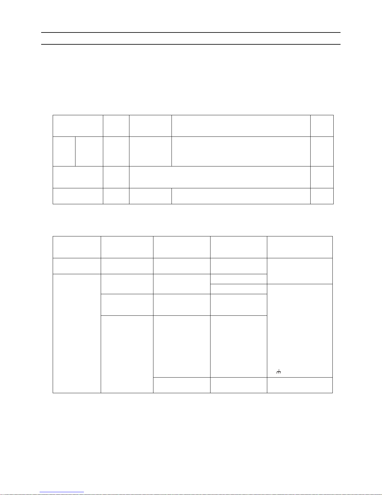
Operation Pipe sections Allowable length of pipes
Length Between outdoor units A+B 10 [32] or less
Total pipe length (L) from the outdoor unit to
the farthest indoor unit
A(B)+C
165 [541] or less
(Equivalent length 190 [623] or less)
Height
difference
Between indoor and outdoor units H 50m [164ft] or less (40m [131ft] or
less when the outdoor unit is lower,
15m [49ft] when the outdoor temperature is 10°C [50°F] or lower)
Between outdoor units h1 0.1 [0.3] or less
Allowable length Total pipe length (L) from the outdoor
unit to thefarthest indoor unit
Actual length 165m [541ft] or less
Allowable height
difference
Height difference between the indoor
and the outdoor units (H)
50m [164ft] or less (40m [131ft] or less when the outdoor
unit is lower, 15m [49ft] when the outdoor temperature is
10°C [50°F] or lower)
Outdoor unit
Indoor
L
H
h1
B
C
A
L
L
H
A
Outdoor unit
Indoor
Page 42

[ II Restrictions ]
- 33 -
HWE1018A GB
2. Refrigerant pipe size
(1) Diameter of the refrigerant pipe between the outdoor unit and the first branch (outdoor unit pipe size)
*1 Use ø12.7 [1/2"] pipes if the piping length exceeds 90 m [295 ft].
(2) Size of the refrigerant pipe between the first branch and the indoor unit (indoor unit pipe size)
Outdoor unit set name
(total capacity)
Liquid pipe size (mm) [inch] Gas pipe size (mm) [inch]
250 model ø9.52 [3/8"] *1 ø22.2 [7/8"]
model Pipe diameter (mm) [inch]
250 model Liquid pipe ø9.52 [3/8"]
Gas pipe ø22.2 [7/8"]
500 model Liquid pipe ø15.88 [5/8"]
Gas pipe ø28.58 [1-1/8"]
Page 43

[ II Restrictions ]
- 34 -
HWE1018A GB
Page 44

- 35 -
HWE1018A GB
III Outdoor Unit Components
[1] Outdoor Unit Components and Refrigerant Circuit .......................................................... 37
[2] Control Box of the Outdoor Unit....................................................................................... 39
[3] Outdoor Unit Circuit Board............................................................................................... 40
Page 45

- 36 -
HWE1018A GB
Page 46

[ III Outdoor Unit Components ]
- 37 -
HWE1018A GB
III Outdoor Unit Components
[1] Outdoor Unit Components and Refrigerant Circuit
1. PUHY-P250YJM-A
(1) Front view of a outdoor unit
Fan
Control
Control
BoxBox
Control
Box
Fan guard
Fin guard
Front panel
Heat exchanger
Heat exchangerHeat exchanger
Page 47

[ III Outdoor Unit Components ]
- 38 -
HWE1018A GB
2. PUHY-P250YJM-A
(1) Refrigerant circuit
High-pressure sensor(63HS1)
High-pressure switch(63H1)
Accumulator
Compressor cover
Compressor
Oil separator
Solenoid valve (SV1a)
Solenoid valve (SV9)Gas-side valve
Liquid-side valve
Linear expansion valve
(LEV2)
2-way valve(SV5b)
Linear expansion valve
(LEV1)
Subcool coil
High-pressure check joint
Low-pressure check joint
4-way valve(21S4a)
4-way valve(21S4b)
Check valve
Low-pressure sensor(63LS)
Page 48

[ III Outdoor Unit Components ]
- 39 -
HWE1018A GB
[2] Control Box of the Outdoor Unit
1) Exercise caution not to damage the bottom and the front panel of the control box. Damage to these parts affect the waterproof and dust proof properties of the control box and may result in damage to its internal components.
2) Faston terminals have a locking function. Make sure the cable heads are securely locked in place. Press the tab on the terminals to remove them.
<HIGH VOLTAGE WARNING>
Control box houses high-voltage parts.
When opening or closing the front panel of the control box, do not let it come into contact with any of
the internal components.
Before inspecting the inside of the control box, turn off the power, keep the unit off for at least 10 minutes,
and confirm that the voltage between FT-P and FT-N on INV Board has dropped to DC20V or less.
(It takes about 10 minutes to discharge electricity after the power supply is turned off.)
Control board
DC reactor (DCL)
Electromagnetic relay(72C)
Noise filter
Note.1
INV board
Fan board
Rush current protection resistor
(R1,R5) Note.2
Terminal block for transmission
line (TB3, TB7)
M-NET board
Terminal block for power supply
L1,L2,L3,N,
(TB1)
Capacitor(C100)
Page 49

[ III Outdoor Unit Components ]
- 40 -
HWE1018A GB
[3] Outdoor Unit Circuit Board
1. Outdoor unit control board
CN332
Output 18VDC
GND
(
Fan board
)
LED2
Lit during normal
CPU operation
CN72
72C
driving output
Serial communication signal input
GND (
INV board)
Output 17VDC
CN801
Pressure switch
connection
CN4
GND
Serial communication signal output
LEV
driving output
LED1
Service LED
SWU1,2
Address switch
SW1-5
Dip
switch
Sensor
input
CNVCC2
Output 12VDC
Output 5VDC
GND
CNIT
Output 12VDC
GND
Output 5VDC
Power supply detection input
Power supply ON/OFF signal output
CNS2
Transmission line input/output
for centralized control system (30VDC)
CN41
Power supply for
centralized control OFF
CN40
Power supply for
centralized control ON
CN102
Indoor/outdoor transmission line input/output (30VDC)
Power supply input for centralized control system (30VDC)
External signal input (contact input)
F01
Fuse
250V AC/3.15A
CNAC
L1
N
LED3
Lit
when powered
LED3
Lit
when powered
Actuator
driving output
Output 12VDC
Compressor
ON/OFF output
Error output
CN51
CNAC2
L1
N
CNDC
Bus voltage input
P
N
CN2
Page 50

[ III Outdoor Unit Components ]
- 41 -
HWE1018A GB
2. M-NET board
Power supply output for centralized control system
Indoor/outdoor transmission line input/output
CN102
CNS2
Transmission line input/output for
centralized control system
CNIT
12VDC input
GND
5VDC input
Power supply detection output
Power supply ON/OFF
signal input
LED1
Power supply for
indoor
transmission line
TP1,2
Check pins for
indoor/outdoor
transmission line
TB7
Terminal block for
transmission line for
centralized control
TB3
Indoor/outdoor
transmission block
Ground terminal for
transmission line
Grounding
Grounding
CN04
Bus voltage input
P
N
Grounding
Page 51

[ III Outdoor Unit Components ]
- 42 -
HWE1018A GB
3. INV board
1) Before inspecting the inside of the control box, turn off the power, keep the unit off for at least 10 minutes, and confirm that
the voltage between FT-P and FT-N on INV Board has dropped to DC20V or less.
It takes about 10 minutes to discharge electricity after the power supply is turned off.
SC-L1
Input(L1)
SC-L2
Input(L2)
SC-L3
Input(L3)
IGBT
(Rear)
Bus voltage check
terminal (P)
Note
Bus voltage check
terminal (N)
Note 1
SC-P2
Bus voltage Input(P)
SC-P1
Rectifier diode output (P)
LED1
Lit: Inverter in normal operation
Blink: Inverter error
CN6
Open: No-load operation setting
Short-circuited: Normal setting
CN5V
GND
5VDC output
RSH1
Overcurrent detection
resistor
CN4
GND
(Fan Board)
Serial communication
signal output
CN2
S
erial communication
signal output
GND
17VDC input
SC-V
Inverter output(V)
CNTYP Inverter
board type
SC-W
Inverter output(W)
SC-U
Inverter output(U)
CT22
Current sensor(W)
CT12
Current sensor(U)
C30 C37
Smoothing capacitor
CN1
Bus voltage output
N
P
CT3
Current sensor(L3)
Page 52

[ III Outdoor Unit Components ]
- 43 -
HWE1018A GB
4. Fan board
CNVDC
Bus voltage input
N
P
CNINV
Inverter output
W
V
U
CN18V
Input 18VDC
GND
LED3
Lit during normal
CPU operation
CN4
GND
Serial communication signal output
CN5
GND(Control board)
Serial communication signal output
CN21
Serial communication signal output
GND(INV board)
Input 17VDC
CN22
GND(INV board)
Input 5VDC
Serial communication signal input
GND(INV board)
Output 17VDC
THBOX
Thermistor
(Control box internal temperature
detection)
LED1
Inverter in normal operation
LED2
Inverter error
DIP IPM Rear
R630,R631
Overcurrent detection
resistor
Page 53

[ III Outdoor Unit Components ]
- 44 -
HWE1018A GB
5. Noise Filter
CN4
Output
(Rectified L2-N current)
P
N
CN5
Output
(Rectified L2-N current)
P
N
TB21
Input/output(L1)
TB22
Input/output(L2)
TB23
Input/output(L3)
TB24
Input(N)
CN1B
Input
L3
L2
CN1A
Input
N
L1
Grounding
F1,F2,F3,F4
Fuse
250VAC 6.3A
CN3
Output
L1
N
Grounding
CN2
Surge absorber circuit
Surge absorber circuit
Short circuit
Short circuit
Page 54

- 45 -
HWE1018A GB
IV Indoor Unit Components
[1] External Dimensions ........................................................................................................ 47
[2] Indoor Unit Components and Internal Structure .............................................................. 49
[3] Control Box of the Indoor Unit.......................................................................................... 53
[4] Indoor Unit Circuit Board.................................................................................................. 54
[5] Separating the top and bottom of the unit........................................................................ 55
Page 55

- 46 -
HWE1018A GB
Page 56

[ IV Indoor Unit Components ]
- 47 -
HWE1018A GB
IV Indoor Unit Components
[1] External Dimensions
1. PFD-P250VM-E model
Unit : mm
390
50
50
100
Note 1. Be sure to set up a trap for Emergency
drain piping.
(Trap height:beyond 100mm)
(Trap is not necessary for main drain piping.)
2. Approve this figure because it is refused
for the improvement and specification
subject to change without notice.
3. Amputate a gas pipe/liquid pipe in the
fixed height at the time of 2 refrigerant
circuit connection, and connect it with
the local pipe.
Drain piping connection
for humidifier
Air inlet
500 or more200 or more
400 or more
800 or more
Indoor unit
Service space
Unit surface
figure
Pipe execution
space
Unit front
figure
Indoor unit
Service space
Hole for the control wiring
Lifting bolts
<2-
ø
32 knock out
hole>
Hole for the power
supply(Body)
<Nomal/Local>
1380
Remote controller
A
Refrig. piping <gas>
ø
22.2 braze
Power supply:White
Operating :Green
Check :Yellow
Failure :Red
(Accessory)
Filter
Lamp
<view from A>
320
220
1950
20
100
462
580
Panel
<
ø
32 knock out hole>
Air inlet
Control box
50
140
Hole for the control wiring <
ø
32 knock out hole>
Main drain piping connection <Rp1-1/4>
<Accessory>
.
Lifting bolts ......4pc.
.
Front panel opening and closing key ......1pc.
100
Air outlet
Refrig. piping <liquid>
ø
9.52 braze
Hole for the power supply <
ø
32 knock out hole>
260
68
100
118 0
780
1340
Hole for the control wiring(
ø
60)
410
68
Hole for the power supply(
ø
60)
321
220
Hole for gas pipe connecting(
ø
42)
Air outlet
20
Bolt holes:8-
ø
18
140
305
100
518
Hole for liquid pipe connecting(
ø
24)
65
<Rp1-1/4>
Hole for liquid pipe connecting(
ø
24)
87
186
20
Emergency drain piping connection <Rp1-1/4>
Hole for gas pipe connecting(
ø
42)
Changeover switch(SW9)
340
100
150
260
171
20
401
740
Page 57

[ IV Indoor Unit Components ]
- 48 -
HWE1018A GB
2. PFD-P500VM-E model
Unit : mm
50100
140
50
50390
100
68
124
135
Note 1. Be sure to set up a trap for Emergency
drain piping.
(Trap height:beyond 100mm)
(Trap is not necessary for main drain piping.)
2. Approve this figure because it is refused
for the improvement and specification
subject to change without notice.
3. Amputate a gas pipe/liquid pipe in the
fixed height at the time of 2 refrigerant
circuit connection, and connect it with
the local pipe.
Refrig. piping <liquid> in 2 refrig. circuit system ø 9.52 braze No.1
Refrig. piping <gas> in 2 refrig. circuit system
type P450:ø 19.05 braze, type P560:ø 22.2 braze No.1
Refrig. piping <liquid> ø 15.88 braze
Refrig. piping <gas> ø 28.58 braze
Hole for No.2 gas pipe
connecting(ø 42) in 2
refrig. circuit system
Hole for No.2 liquid pipe
connecting(ø 24) in 2
refrig. circuit system
Hole for liquid pipe connecting(ø 34)
Hole for No.1 liquid pipe connecting
(ø 24) in 2 refrig. circuit system
Bolt holes:8-ø 18
Hole for No.1 gas pipe connecting(ø 42)
in 2 refrig. circuit system
Hole for gas pipe connecting(ø 48)
Main drain piping connecting<Rp1-1/4>
Drain piping connection
for humidifier
<Accessory>
· Lifting bolts ······4pc.
· Front panel opening and closing key ······1pc.
Air inlet
Service space
Indoor unit
Pipe execution
space
Panel opening
and closing
dimension
Indoor unit
Unit surface
figure
Service space
400 or more
Unit front
figure
1000 or more *1
200 or more
*1. It is necessary for the removal
of the panel beyond 600mm.
500 or more
710
Refrig. piping <gas> in 2 refrig. circuit system
type P450:ø 19.05 braze,
type P560:ø 22.2 braze No.2
680
<2-ø 32 knock out
hole>
<ø 32 knock out hole>
Air outlet
Air inlet
Power supply :White
Operating :Green
Check :Yellow
Failure1 :Red
Failure2 :Red
<Normal/Local>
(Accessory)
<view from A>
<Rp1-1/4>
Air
outlet
Hole for liquid side pipe connecting
or No.1 gas side pipe connecting(ø 42)
in 2 refrig. circuit system
Hole for No.2 gas side pipe connecting(ø 42)
in 2 refrig. circuit system
100 1001780
1940
100
2020
20
65
321
100
410
359 241
740
359
580
305
320
220
370
20
Emergency drain piping connection <Rp1-1/4>
Hole for No.1 liquid side pipe connecting
(ø 24) in 2 refrig. circuit system
Hole for the power supply(ø 60)
1950
780
Hole for gas side pipe connecting or
No.2 liquid side pipe connecting(ø 48)
in 2 refrig. circuit system
440
Air
outlet
185
379
135
Refrig. piping <liquid> in 2 refrig. circuit
system ø 9.52 braze No.2
68
120
Hole for the control wiring <ø 32 knock out hole>
Hole for the power supply <ø 32 knock out hole>
220
150
81
Hole for the control wiring(ø 60)
Panel
68
Lifting bolts
171
A
Control box
Lamp
Filter
Remote controller
838
Hole for the control wiring
1980
124
68
Hole for the power
supply(Body)
Changeover switch (SW9)
Page 58

[ IV Indoor Unit Components ]
- 49 -
HWE1018A GB
[2] Indoor Unit Components and Internal Structure
1. PFD-P250VM-E model
(1) Front view of a indoor unit
(2) Rear view of a indoor unit
Lock key X 2
Display lamp
Panel for refrigerant circuit maintenance
Panel for air filter maintenance
Operation panel (remote controller)
Panel for controller/fan related parts maintenance
Page 59

[ IV Indoor Unit Components ]
- 50 -
HWE1018A GB
(3) Front view of internal structure
(4) Rear view of internal structure
Heat exchanger X 2 (front / back)
Sub drain pan
Suction temperature thermistor
(on the right side of heat exchanger)
Linear expansion valve (LEV)
Drain pan
Drain hose
Pulley X 2
Pipes (gas/liquid)
Fan motor
V belt
Controller
Air filter
Fan casing
(on the back of controller)
Discharge temperature thermistor
(on the left side of fan casing)
Drain hose
Pipes (ga /liquid)
Fan casing
Page 60

[ IV Indoor Unit Components ]
- 51 -
HWE1018A GB
2. PFD-P500VM-E model
(1) Front view of a indoor unit
(2) Rear view of a indoor unit
Lock key X 4
Panel for controller maintenance
Display lamp
Operation panel (remote controller)
Panel for fan related parts maintenance
Panel for refrigerant circuit maintenance
Panel for air filter maintenance
Page 61

[ IV Indoor Unit Components ]
- 52 -
HWE1018A GB
(3) Front view of internal structure
(4) Rear view of internal structure
Remote controller
Float switch X 2
Drain pan
Display lamp
Normal/Local switching switch(SW9)
Heat exchanger X 2 (front:No. 1; back:No. 2)
Sub drain pan
Suction temperature thermistor
(on the right side of heat exchanger)
Linear expansion valve (LEV)
Drain pan
Operation panel
Bearing
Drain hose
Pulley X 2
Pipes (gas/liquid)
Fan motor
V belt
<Location of drain pan overflow detection float switch>
Controller
Air filter
Fan casing
Discharge temperature thermistor
(on the left side of fan casing)
Bearing
Pipes (gas/liquid)
Page 62

[ IV Indoor Unit Components ]
- 53 -
HWE1018A GB
[3] Control Box of the Indoor Unit
1. PFD-P250VM-E model
2. PFD-P500VM-E model
Circuit board for external I/O
Terminal block for transmission line (upper)
Terminal block for MA remote controller (lower)
Power supply terminal bed
Surge absorber board
Motor wiring
Surge breaker (51F)
Fuse (F1)
Electro magnetic
contactor (52F)
Relay(X11,Z1,Z3)
Controller board
Transformer
Circuit board for external I/O
Terminal block for transmission line on No.2 side (upper)
Terminal block for MA remote controller (lower)
Power supply terminal bed
Terminal block for transmission
line on No.1 side
Motor wiring
Surge breaker (51F)
Electro magnetic
contactor (52F)
Relay(X11,X12,Z1,Z2,Z3)
Controller board
Transformer
Adapter board for LEV
Surge absorber board
Fuse (F1)
Page 63

[ IV Indoor Unit Components ]
- 54 -
HWE1018A GB
[4] Indoor Unit Circuit Board
1. PFD-P250,P500VM-E models
(1) Indoor Control Board
(2) External Input/Output Circuit Board
CND
Power supply
input
(AC 220~240V)
F901
Fuse
CN2M
Indoor unit
transmission
line
CN3T
Power supply input
(from transformer)
CNT
Power supply output
(to transformer)
CN90
Fan output
CNP
Drain pump
output
CN60
LEV output
SW1,2,3,4
Dip switch
CN24
Control signal
output
CN51
Switch input
LED1
LED2
CN31
Float switch input
CN32
Switch input
SW5
SWC
Switching between
discharge/suction control
Thermistor input
CN20
CN21
CN29
CN22
CN33
Lamp output
CN3A
Remote controller connection
CN53
Indoor control board (No.1)
To C N51
CN54
Indoor control board (No.2)
To C N51
TB22 (Relay contact output)
No.1 operation status
No.1 error status
No.2 operation status
No.2 error status
TB23 (Input with voltage)
ON/OFF
TB21 (Input no voltage)
ON/OFF
Page 64

[ IV Indoor Unit Components ]
- 55 -
HWE1018A GB
[5] Separating the top and bottom of the unit
< Model 250 >
Filters (2)
Filter cover
Side panel: 14 screws
Front panel: 6 screws
Front panel:
2 chains
Rear panel: 9 screws
Side panel: 14 screws
Rear panel: 8 screws
A
(on four corners)
Filters (3)
Rear panel: 7 screws on each
Filter cover
Rear panel: 8 screws
Side panel: 14 screws
A
(on four corners)
Front panel:
2 hinges on each
Side panel:
14 screws
Bolt
Screw
Pull these pins up and down respectively
to remove the front panel.
Bolt
Screw
Detailed vie w of section A
< Model 500 >
Heat exchanger
unit (top)
Fan unit
(bottom)
Height (mm)
1120+510
*1
860
<Dimensions and weight of parts>
* Length of protruded pipe (removable)
Width (mm)
P250:1380
P500:1980
P250:1380
P500:1980
Depth (mm)
780
780
Weight (kg)
P250:158
P500:246
P250:128.5
P500:159
[Fig.1]
The top and the bottom of the unit can be separated.
(Requires brazing)
When separating the top and the bottom of the unit, perform the work on a level
surface.
Follow the procedures below when separating the sections.
Necessary tools and materials:
Ratchet wrench with a socket size of 17 mm (for M10)
General tools
Cable ties (for wires)
Gray vinyl tape (for pipes)
Supporting wood piece Height 800 mm x width 100 mm x thickness 20 (mm)
1 piece
(1) Removing the decoration panel and filter
<Model 250>
Remove the front panels (2), rear panels (2), and the side panels (2) in this
order by removing the hinges and the screws on the unit as shown in [Fig.1].
Open the filter cover and remove the filters (2 filters).
<Model 500>
Remove the front panels (4), rear panels (3), and the side panels (2) in this
order by removing the hinges and screws on the unit as shown in [Fig.1].
Open the filter cover and remove the filters (3 filters).
(2) Disconnecting the electric wires
Disconnect the wiring connectors from the remote controller, thermistor, float
switch, lamp , and linear expansion valve as shown in [Fig.2].
After removing the connectors, pull out the wires from the control box.
Unclamp the wires from the frame.
Put all wires together in a bundle on the unit.
(3) Removing the drain hose and the pipes from the brazed section of the pipe
Remove the drain hose by unscrewing the screws on both ends of the hose
band.
Peel off the pipe cover on the pipe so that the torch flame will not reach the
cover. Remove the pipe from the brazed section as shown in [Fig.3].
*Protect the section around the area to be worked on from the torch flame
(drain pan, wiring, insulation material on the frame etc).
1
2
(4) Separate the top and the bottom of the unit
Unscrew the screws and loosen bolt that are marked with the letter A in
Loosen bolt
[Fig.1] (on f our corners)
loose enough to allow the top and
the bottom of the unit to be separated. Be sure to re-tighten bolt after sepa
and bottom (Tightening torque:
rating the top
74N.m).
Separation work is now complete. Exercise caution not to damage or scratch the
unit during transportation or get your fingers caught between the units.
1
2
2
Page 65

[ IV Indoor Unit Components ]
- 56 -
HWE1018A GB
Clamp
Clamp
Linear expansion valve wiring
Thermistor wiring
Float switch wiring
Lamp wiring
Remote controller wiring
No. 2
No. 1
[Fig.2]
<Model 500>
<Model 250>
(the wire from the lamp assy.)
Bend the wire once, and fix the wire.
Fix the wire from the fan motor.
Connect the wire from the lamp assy.
Connect the wire from the lamp assy.
Page 66

[ IV Indoor Unit Components ]
- 57 -
HWE1018A GB
Drain pan
Heat exchanger
(gas pipe)
Heat exchanger
(liquid pipe)
Unbraze these sections
(2 places on the gas pipe
/upper part of the strainer)
Heat exchanger
(liquid pipe)
Heat exchanger
(gas pipe)
Drain pan
<Model 500>
<Model 500>
<Model 250>
<Model 250>
Unbraze these sections
(2 places on the liquid pipe
/upper part of the strainer)
[Fig. 3]
To p
Bottom
Bottom section of the unit
Top section of the unit Bottom section of the unit Top section of the unit
Bottom Bottom Bottom
To p To p To p
Control box
Motor
Control box
Motor
Fan
Supporting
wood piece
Supporting
wood piece
Heat exchanger
Piping side
Heat exchanger
Piping side
Fan
Note
1. Peel off the pipe cover carefully. The cover will be needed again when putting the units together.
2. When loading the unit on an elevator, place the separated sections upright as shown below.
(Place the right side up.) Place a piece of wood at the bottom of the bottom section for support to keep it level.
Unbraze this section
(1 place on the liquid pipe/
upper part of the strainer)
Unbraze these sections
(2 places on the gas pipe/
expanded part)
Page 67

[ IV Indoor Unit Components ]
- 58 -
HWE1018A GB
Caution
To put the top and bottom sections of the unit together, follow the procedures above in the reverse order.
Use a hand-lift truck to transport the units; they are heavy even when the top and button sections are separated.
Carrying the units by hand is dangerous and may result in personal injury if the units fall or topple over.
Exercise caution not to get your fingers caught when separating or assembling the top and bottom sections of
the unit.
Check to make sure that the frame is perpendicular to the horizontal plane before putting the panels together.
When the frames will not fit back into place, loosen bolt 2 as shown in [Fig.1], place the frames, and tighten bolt 2 .
Keep torch flame away from the insulation material on the drain pan and from other flammable materials when
performing brazing work. Use the shielding board that is supplied.
Be sure to securely tighten all screws and bolts. (tightening torque: 74N.m)
Perform a test run and check for abnormal sound, rattling, and water leaks.
Using [Fig.4] and Table 1 as a reference, connect all connectors correctly.
Use a cable tie and bundle the wires as they were before.
<Model 250>
No. 1 board
Connector location on the board
CN60
CN31
CN20
CN21
CN29
CN22
Connector location on the board Connector location on the adapter board
No. 1 board
CN31
CN20
CN21
CN29
*Same with the No. 2 board
LEV2B
LEV2A
<Model 500>
Board No.
No.1
Connector
CN31
CN20
CN21
CN29
CN60
Table 1
Table 1
Wire
mark
1
S1
E1
G1
V1
Connector
color
White
Red
White
Black
White
No. of
pins
3
2
2
2
6
Parts name
Float switch
Inlet thermistor
Liquid pipe thermistor
Gas pipe thermistor
Linear expansion valve
Board No.
No.1
No.2
Connector
CN31
CN20
CN21
CN29
LEV2A
CN31
CN20
CN21
CN29
LEV2B
Wire
mark
1
S1
E1
G1
V1
2
S2
E2
G2
V2
Connector
color
White
Red
White
Black
White
White
Red
White
Black
White
No. of
pins
3
2
2
2
6
3
2
2
2
6
Parts name
Float switch
Inlet thermistor
Liquid pipe thermistor
Gas pipe thermistor
Linear expansion valve
Float switch
Inlet thermistor
Liquid pipe thermistor
Gas pipe thermistor
Linear expansion valve
[Fig. 4]
[Fig. 4]
Page 68

- 59 -
HWE1018A GB
V Electrical Wiring Diagram
[1] Electrical Wiring Diagram of the Outdoor Unit ................................................................. 61
[2] Electrical Wiring Diagram of the Indoor Unit .................................................................... 62
Page 69

- 60 -
HWE1018A GB
Page 70

[ V Electrical Wiring Diagram ]
- 61 -
HWE1018A GB
V Electrical Wiring Diagram
[1] Electrical Wiring Diagram of the Outdoor Unit
1. Electrical wiring diagram of the outdoor unit
(1) PUHY-P250YJM-A
+-
++++
2
1
+
++
++
3
3
2
2
Heat exchanger capacity control
Cooling/Heating switching
21S4b
63HS1
SV9
SV5b
For opening/closing the bypass
circuit under the O/S
21S4a 4-way valve
Explanation
Symbol
63H1
63LS
Pressure
sensor
Pressure
switch
High pressure protection for the
outdoor unit
Discharge pressure
Low pressure
72C
Magnetic relay(inverter main circuit)
Current sensor(AC)
Crankcase heater(for heating the compressor)
CH11
CT12,22,3
HIC bypass,Controls refrigerant
flow in HIC circuit
Solenoid
valve
Linear
expansion
valve
LEV1
LEV2
SV1a
DCL DC reactor
Pressure control,Refrigerant flow
rate control
TB1
TB3
TB7
Terminal
block
Central control transmission
cable
Indoor/Outdoor transmission
cable
Power supply
TH2
TH3
TH4
TH5
TH6
TH7
THHS
Function setting connector
IPM temperature
OA temperature
Subcooled liquid refrigerant
temperature
ACC inlet pipe temperature
Discharge pipe temperature
Subcool bypass outlet
temperature
Thermistor
Z24,25
Pipe temperature
Outdoor unit heat exchanger
capacity control
For opening/closing the bypass
circuit
153
6
3
CN3
green
1
N
N
L
N
TB24
*1.Single-dotted lines indicate wiring not supplied with the unit.
*2.Dot-dash lines indicate the control box boundaries.
*3.Refer to the Data book for connecting input/output signal connectors.
*4.Daisy-chain terminals (TB3) on the outdoor units in the
same refrigerant system together.
*5.Faston terminals have a locking function.
Make sure the terminals are securely locked
in place after insertion. Press the tab
on the terminals to remove them.
*6.Control box houses high-voltage parts.
Before inspecting the inside of the
control box,turn off the power,keep
the unit off for at least 10 minutes,
and confirm that the voltage between
FT-P and FT-N on INV Board has dropped
to DC20V or less.
L3
L1
L2
Power Source
3N~
50/60Hz
380/400/415V
21S4b
CN501
X01
1
3
X09
3
6
CN508
black
Unit address
setting
CN504
green
CT12
C31
C33
CN5
red
D1
R4
Z5
1
SV9
R631
white
TH2
t
°
C8
red
CNIT
yellow
CNS2
t
°
1
1
LED1
Display
setting
CN51
12V
Function
setting
SW1
10
1
CN212
CNTYP4
green
F4
AC250V
6.3A T
R5
F3
F1
Z4
R2
F2
*3
3
2
Compressor ON/OFF output
Error detection output
CN201
Z25
1
4
1
1
1
TH3
Z3
3
Z2
U
ONOFF
SW2
10
1
SWU2
LED1
C4
C35
C37
R31
R33
R30
ON
SW3
10
Control Board
TH7
CN40
63HS1
CN41
TH6
t
°
t
TH4
3
2
2
2
1
SW5
LED3:Lit when powered
1
3
4
R32
2
Z1
1
DSA
C10
R34 R35
LEV1
LEV2
C36
3
C34
SC-V
CT22
SC-U
V
1
CN4
blue
red
1
M
1
1
t
LED3:CPU in
operation
black
4
1
CNTYP2
black
3
6
yellow
CN3K
*3
3
M
C3
TB21
C1
R3
3
CN1A
5
U
CN2
blue
CN3N
5
6
C7
U
44
R1
CN21
blue
TB1
1
CN1B
3
TB7 Power
selecting
connector
CN102
CNVDC
3
2
1
IPM
2
1
U
4
TP1
W
L3
DCL
V
black
72C
white
red
321
ON
OFF
1
M-NET power
supply circuit
123
C6
M-NET Board
12
1
Power failure
detection circuit
1
CNAC2
black
CN502
5
Indoor/Outdoor
transmission
cable
INV Board
red
3
CNT01
TB23
L2L1
U
4
1
ON
1
2
1's
digit
THHS
1
CNIT
red
S
2
1
1
CN990
1
3
W
TB3
10's
digit
OFF
LED2:CPU in operation
5
2
CNS2
yellow
TB7
1
CNDC
pink
M1
2
2
red
6
MS
3~
1
1
t
C100
*5
3
3
U
1
4
LED1:Power supply to
Indoor/Outdoor
transmission line
ZNR01
M2
32
M1
black
Central control
transmission
cable
*6
SC-L1
1
4
C2
C9
ON
C5
OFF
FT-N
R5
M
3~
Motor
(Compressor)
°
CN5V
yellow
5
2
3
3
3
red
CN3S
1
1
CN04
red
1
CN2
2
3
CN4
X05
2
2
Fan motor
(Heat exchanger)
SC-P2
P
1
CN211
CN202
red
TH5
°
N
CN1
M2
2
TP2
LED1:Normal operation(Lit)
/ Error(Blink)
2
CN503
blue
5
X04
4
*4
SC-W
U
C32
SC-L3
CH11
CN506
1
2
CN72
red
3
P
63H1
CN801
yellow
1
2
CN332
blue
F1,F2,F3
AC250V
6.3A T
21
OFF
SW4
10
1
CNT02
11
CN3D
432
1
21
CPU power
supply circuit
CNAC
red
2
1
F01
AC250V
3.15A T
1
t
ONOFF
10
SWU1
white
CN213
red
SC-L2
3
Z24
7
4
°
3 21122
7
1
2
CN5
1
CN4
red
CNINV
3
4
R630
1
1
C630
3
CN22
red
C631
5
F01
DC700V
4A T
1
CNTYP5
green
4
LED2:Error
21S4a
1
LED1:Normal
operation
2
3
2
U
X02
X03
CN18V
blue
5
1
7
CN4
3
CN6
2
°
IPM
4
SC-P1
FT-P
black
C30
red
DB1
CT3
72C
C1
CN2
CNTYP
black
R1
black
TB22
6
3
RSH1
CN102
3
R6
C11
1
1
1
FAN Board
63LS
ZNR1
U
3
Noise
Filter
SV5b
red
CNLVA
CNLVB
red
12345
6
white
black
SV1a
6
432
1
2
1
L1 L2 L3
CN215
black
<Symbol explanation>
Page 71

[ V Electrical Wiring Diagram ]
- 62 -
HWE1018A GB
[2] Electrical Wiring Diagram of the Indoor Unit
1. PFD-P250VM-E
u
Note: 1. The dotted lines show field wiring.
2. The address setting of the indoor unit should always be odd.
3. The outdoor unit to which the indoor unit is connected with the transmission line,
the address of the outdoor unit should be the indoor unit +50.
4. Mark indicates terminal bed, connector, board insertion connector
or fastening connector of control board.
0
F
E
D
C
B
A
9
0
9
8
7
6
5
4
3
2
1
9
1
2
3
4
5
6
7
8
0
8
7
6
5
4
3
2
1
2121
7123456
CN7V
CN24 CN25
X11
SW8
SW4
SW11
(1st digit)
SW12
(2nd digit)
SW14
SW7 SW2 SW1SW3
SWC SW5
Address
(odd)
1234561232121212112
T
CN3T
3
CN28 CN31CN29CN20 CN21 CN60CN22
Z3
33P1
97513131311
CNT CND
CN90CN33
CNP
5432
1
65432
CN51
1
CN52
Dehumidify
ZNR901
DSA1
CN3A
ZNR1
F901
X06 X05
X04
321
2
CN32
321
X01
CN2M
I.B.
1
X07
Z1
Inside section of control box
RC
2
1
2
1
TB15
Failure output
Distant location on/off
<no voltage or current>
Status output
Distant location on/off
<with voltage and current>
Power supply DC30V, AC100/200V
Switch(normal/local)
Power supply DC12~24V
Power supply
380/400/415V(50Hz)
400/415V(60Hz)
DC24~30V
Indoor unit
Control wiring
LED display(failure)
LED display(status)
LED display(power supply)
3N~
LED display(check)
SW9
234515432
1
B2B1BCA2A1
AC
54321
C
IFB
3
L3
A1SB1
L2
L1
X11
1
2
216
5
1
2
PE
N
F1
345
6
3
1
ZNR1
3
1
CN1
DSA1
PE
TB23
TB21
L
L
TB22
CN53
TB2
S.B.
CN54
L3
TB5
SHIELD
L2
L1
L4
FAN
over current
detection
51F
Z1
ZNR2
52F
Z3
51F
52F
MF
TH24
TH21
TH22
TH23
65432
1
LEV
SYMBOL
NAME
DSA1
Surge absorber
LED display (power supply)
F901
ZNR1, ZNR2, ZNR901
MF
I.B.
S.B.
IFB
TB2
TB5
TB15
TB21
TB22
TB23
F1TLEV
52F
51F
33P1
RC
L4
L3
L2
L1
Z3
Z1
X11
SWC(I.B.)
SW14(I.B.)
SW12(I.B.)
SW11(I.B.)
SW9
SW4(I.B.)
SW3(I.B.)
SW2(I.B.)
SW1(I.B.)
Surge absorber board
Switch (outlet/inlet temp.control)
Float switch
Fuse<6-3/6A>
Varistor
Transformer
Electronic linear expan.valve
Contactor(fan I/D)
Over current relay (fan I/D)
Fuse<5A>
Thermistor (inlet temp.detection)
Switch (connection No.set)
Switch (for mode selection)
Switch (for capacity code)
Switch (for mode selection)
Switch (for model selection)
Auxiliary relay(check)
LED display (failure)
LED display (status)
LED display (check)
Switch (normal/local)
TH24
TH23
TH22
TH21
Switch (1st digit address set)
Switch (2nd digit address set)
Fan motor
Indoor controller board
Power source terminal bed
Transmission terminal bed
External input/output board
Transmission terminal bed
MA Remote controller
Terminal bed for distant location on/off
<With voltage and current>
Terminal bed for distant location on/off
<No voltage or current>
Auxiliary relay(fan failure detection)
Auxiliary relay(fan)
Thermistor (piping temp.detection/gas)
Thermistor (piping temp.detection/liquid)
Thermistor (outlet temp.detection)
Terminal bed for distant location display
External input adapter
(PAC-SA88HA)
CN52
5(green)
1(brown)
Z
Indoor unit
control board
Relay circuit
The signal input of the dehumidify order is to
connect wiring referring to the bottom figure.
SW
Power
Distant control panel
SW:Defumidify order
(field supply
and construction)
Z
Z:Relay (Contact : Minimum applicable load
DC12V 1mA or less)
u
u
u
t
ttt
Page 72

[ V Electrical Wiring Diagram ]
- 63 -
HWE1018A GB
2. PFD-P500VM-E
ttt
t
ttt
t
1. The dotted lines show field wiring.
2. It is wiring for 1 refrigerant system at the time of shipping.
Change wiring and SW2, 3, 4 (No.1&No.2) as this figure in field
when you change it to 2 refrigerant circuit
3. Set up the address of No.1 board in the odd number, and set up the
address of No.2 board in the even number.
But, set up the address of the No.2 board in the No.1 board +1.
4. The outdoor unit to which the indoor unit is connected with the
transmission line, the address of the outdoor unit should be the
indoor unit +50.
5. Mark indicates terminal bed, connector, board insertion connector
or fastening connector of control board.
Note:
SW8
SW4 SW7 SW2
SWC SW5
0
F
E
D
C
B
A
9
0
9
8
7
6
5
4
3
2
1
9
1
2
3
4
5
6
7
8
0
8
7
6
5
4
3
2
1
6574321CN24 CN25
1
2
2
1
X11
CN7V
Address
(odd)
SW11
(1st digit)
SW12
(2nd digit)
SW14
No.1
CN51
CN52
Dehumidify
13
45
1
2
3
45
2
ZNR901
DSA1
ZNR1
F901
X06 X05 X04X01 X07
CN3A
CN32
CN2M
I.B.1
3212321
1
591513731
CNT
CND
CN90
13
CN33CNP
31
Z1
T
CN3T
31
CN28
21
CN31
12321
CN29
3222
1
11
CN20
CN21
CN60
CN22
21 654
Z3
33P1
SW1SW3
TH24-1
TH21-1
TH22-1
TH23-1
LEV2
LEV1
12345
6654321
AD.B.
6543 126543 12
6543 12
LEV1A
LEV1B
LEV1
2
1
Inside section of control box
RC
2
1
TB15
A1SB1
216
5
DC24~30V
No.1 Indoor unit
Control wiring
LED display(No.1 failure)
LED display(status)
TB5-1
SHIELD
L3
L1
1
3
ZNR1
3
1
CN1
DSA1
S.B.
3
L3
L2
L1
1
2
N
F1
Power supply
3N~
380/400/415V(50Hz)
400/415V(60Hz)
LED display(power supply)
PE
TB2
L5
345
6
Switch(normal/local)
SW9
No1.Failure output
Distant location on/off
<no voltage or current>
No1.Status output
Distant location on/off
<with voltage and current>
No2.Status output
No2.Failure output
Power supply DC30V, AC100/200V
Power supply DC12~24V
LED display(No.2 failure)
DC24~30V
No.2 Indoor unit
Control wiring
LED display(check)
L4
L2
L
L
L
L
54321
S
A2
B2
B2B1BCA2A1
AC
54321
C
IFB
CN54
TB22
CN53
TB21
TB23
SHIELD
TB5-2
3
4
X11
1
2
PE
X12
<note2>
CN3A1CN2M
123
CN32
213
2
123
1
I.B.2
54321
CN52
54321
CN51
Dehumidify
ZNR901
F901
ZNR1
DSA1
X01
X07
X04X05X06
CNP CN33
CN90
CND
CNT
CN3T
12
CN22 CN21CN20
1122
CN29
12321
CN31
12
CN28
531
CN60
1234563113 731 51139
Z2
<note2>
33P2
T
Z3
CN25CN24
12 CN7V
1234567
21
X12
SW5
SWC
SW12
(2nd digit)
SW11
(1st digit)
SW8
Address
(odd)
SW3 SW1SW2SW7SW4
SW14
0
F
E
D
C
B
A
9
0
9
8
7
6
5
4
3
2
1
9
1
2
3
4
5
6
7
8
0
8
7
6
5
4
3
2
1
No.2
FAN
over current
detection
51F
Z1
ZNR2
Z2
52F
Z3
TH24-2
TH21-2
TH22-2
TH23-2
51F
52F
MF
NAME
SYMBOL
Surge absorber
DSA1
L5
ZNR1, ZNR2, ZNR901
LED display (No.2 failure)
LED display (status)
LED display (check)
LED display (power supply)
MA Remote controller
RC
TB21
TB15
TB5-1, -2
TB2
IFB
S.B.
AD.B.
I.B.1, I.B.2
MF
Surge absorber board
Switch (outlet/inlet temp.control)
Float switch
Varistor
Transformer
Electronic linear expan.valve
Contactor(fan I/D)
Over current relay (fan I/D)
Thermistor (inlet temp.detection)
Switch (connection No.set)
Switch (for mode selection)
Switch (for capacity code)
Switch (for mode selection)
Switch (for model selection)
Auxiliary relay(check)
LED display (No.1 failure)
Switch (normal/local)
TH24-1, TH24-2
SW1(I.B.)
SW2(I.B.)
SW3(I.B.)
SW4(I.B.)
SW11(I.B.)
SW12(I.B.)
SW14(I.B.)
SWC(I.B.)
X11, X12
Z1, Z2Z3L1L2L3
L4
SW9
TH23-1, TH23-2
TH22-1, TH22-2
TH21-1, TH21-2
33P1, 33P2
51F
52F
LEV1, 2
T
F1
F901
TB23
TB22
Switch (1st digit address set)
Switch (2nd digit address set)
Fan motor
Indoor controller board
Adapter board
Power source terminal bed
Transmission terminal bed
External input/output board
Transmission terminal bed
Terminal bed for distant location on/off
<With voltage and current>
Terminal bed for distant location on/off
<No voltage or current>
Auxiliary relay(fan failure detection)
Auxiliary relay(fan)
Thermistor (piping temp.detection/gas)
Thermistor (piping temp.detection/liquid)
Thermistor (outlet temp.detection)
Terminal bed for distant location display
Fuse <6.3/6A>
Fuse <5A>
(field supply
and construction)
Power
SW
Indoor unit
control board
Z
1(brown)
5(green)
CN52
The signal input of the dehumidify order is to
connect wiring referring to the bottom figure.
Relay circuit
External input adapter
(PAC-SA88HA)
SW:Defumidify order
Z:Relay (Contact : Minimum applicable load
DC12V 1mA or less)
Distant control panel
Z
How to connect in case of 2 refrigerant circuit.
Remove the LEV1B connector
from AD.B. board, and
connect it to CN60 of
I.B.2 board.
Connect a connector to
CN3A, CN2M of I.B.2
board.
<note2>
65432
1
CN60
654321
CN3A
CN2M
I.B. 2
12321
LEV2
<note2>
How to set up to SW2, 3, 4.
(In case of 2 refrigerant circuit)
PFD-P500VM-E
(at the time of shipping)
ON
654321
ON
65432110987
ON
54321ON5432110987
ON
654321
ON
654321
2 refrigerant
circuit
1 refrigerant
circuit
SW2 SW3 SW4
External input-output
board (IFB)
The case of with-voltage input
...
A
The case of no-voltage input
....
B
When using the external input function on the indoor unit
that is connected to a two-refrigerant circuit, connect the
short-circuit plate that is supplied with the unit to the
appropriate terminals on the external input-output board.
ACA1A2BCB1
B2
A
B
TB23
TB21
u
u
u
u
u
u
Page 73

[ V Electrical Wiring Diagram ]
- 64 -
HWE1018A GB
Page 74

- 65 -
HWE1018A GB
VI Refrigerant Circuit
[1] Refrigerant Circuit Diagram ............................................................................................. 67
[2] Principal Parts and Functions .......................................................................................... 70
Page 75

- 66 -
HWE1018A GB
Page 76

[ VI Refrigerant Circuit ]
- 67 -
HWE1018A GB
VI Refrigerant Circuit
[1] Refrigerant Circuit Diagram
1. System with one refrigerant
(1) PUHY-P250YJM-A
SCC (HIC Circuit)
LEV1
SV1a
ACC
63HS1
21S4a
ST3
ST6
63H1
CJ2
ST7
TH4
TH2
TH3
TH7
TH6
21S4b
TH5
CP1
CJ1
63LS
SV5b
COMP
O/S
CV1
LEV2
ST1
ST2 BV2
BV1
SV9
CP2
TH23
TH22
Page 77

[ VI Refrigerant Circuit ]
- 68 -
HWE1018A GB
(2) PUHY-P500YSJM-A
LEV1
SV1a
ACC
63HS1
21S4a
ST3
ST6
63H1
CJ2
ST7
TH4
TH2
TH3
TH7
TH6
21S4b
TH5
CP1
CJ1
63LS
SV5b
COMP
O/S
CV1
LEV2
ST1
ST2 BV2
BV1
SV9
CP2
TH22
LEV1
SV1a
ACC
63HS1
21S4a
ST3
ST6
63H1
CJ2
ST7
TH4
TH2
TH3
TH7
TH6
21S4b
TH5
CP1
CJ1
63LS
SV5b
COMP
O/S
CV1
LEV2
ST1
ST2 BV2
BV1
SV9
CP2
TH23
Gas twinning
pipe
Liquid twinning
pipe
SCC
(HIC circuit)
SCC
(HIC circuit)
Page 78

[ VI Refrigerant Circuit ]
- 69 -
HWE1018A GB
2. System with two refrigerant circuits
(1) PUHY-P250YJM-A x 2
SCC
(HIC Circuit)
LEV1
SV1a
ACC
63HS1
21S4a
ST3
ST6
63H1
CJ2
ST7
TH4
TH2
TH3
TH7
TH6
21S4b
TH5
CP1
CJ1
63LS
SV5b
COMP
O/S
CV1
LEV2
ST1
ST2 BV2
BV1
SV9
CP2
TH22-1
SCC
(HIC Circuit)
LEV1
SV1a
ACC
63HS1
21S4a
ST3
ST6
63H1
CJ2
ST7
TH4
TH2
TH3
TH7
TH6
21S4b
TH5
CP1
CJ1
63LS
SV5b
COMP
O/S
CV1
LEV2
ST1
ST2 BV2
BV1
SV9
CP2
TH23-1
TH22-2
TH23-2
Page 79

[ VI Refrigerant Circuit ]
- 70 -
HWE1018A GB
[2] Principal Parts and Functions
1. Outdoor unit
Part
name
Symbols
(functions)
Notes Usage Specifications Check method
Compressor
MC1
(Comp1)
Adjusts the amount of circulating
refrigerant by adjusting the operating frequency based on the operating pressure data
250 models
Low-pressure shell scroll
compressor
Wirewound resistance
20°C[68°F] : 0.981ohm
High
pressure
sensor
63HS1 1) Detects high pressure
2) Regulates frequency and provides high-pressure protection
Low
pressure
sensor
63LS 1) Detects low pressure
2) Provides low-pressure protection
Pressure
switch
63H1 1) Detects high pressure
2) Provides high-pressure protection
4.15MPa[601psi] OFF setting
Pressure
0~4.15 MPa [601psi]
Vout 0.5~3.5V
0.071V/0.098 MPa [14psi]
Pressure [MPa]
=1.38 x Vout [V]-0.69
Pressure [psi]
=(1.38 x Vout [V] - 0.69) x 145
GND (Black)
Vout (White)
Vcc (DC5V) (Red)
Connector
63HS1
1
123
2
3
Pressure
0~1.7 MPa [247psi]
Vout 0.5~3.5V
0.173V/0.098 MPa [14psi]
Pressure [MPa]
=0.566 x Vout [V] - 0.283
Pressure [psi]
=(0.566 x Vout [V] - 0.283) x 145
GND (Black)
Vout (White)
Vcc (DC5V) (Red)
Connector
63LS
1
123
2
3
Page 80

[ VI Refrigerant Circuit ]
- 71 -
HWE1018A GB
Thermistor
TH4
(Discharge)
1) Detects discharge air temperature
2) Provides high-pressure protection
Degrees Celsius Resistance
check
0°C[32°F] :698kohm
10°C[50°F] :413kohm
20°C[68°F] :250kohm
30°C[86°F] :160kohm
40°C[104°F] :104kohm
50°C[122°F] : 70kohm
60°C[140°F] : 48kohm
70°C[158°F] : 34kohm
80°C[176°F] : 24kohm
90°C[194°F] :17.5kohm
100°C[212°F] :13.0kohm
110°C[230°F] : 9.8kohm
TH2 LEV 1 is controlled based on the
TH2, TH3, and TH6 values.
Degrees Celsius
0°C[32°F] :15kohm
10°C[50°F] :9.7kohm
20°C[68°F] :6.4kohm
25°C[77°F] :5.3kohm
30°C[86°F] :4.3kohm
40°C[104°F] :3.1kohm
Resistance
check
TH3
(Pipe
temperature)
1) Controls frequency
2) Controls defrosting during
heating operation
3) Detects subcool at the heat
exchanger outlet and controls
LEV1 based on HPS data
and TH3 data
TH7
(Outdoor temperature)
1) Detects outdoor air temperature
2) Controls fan operation
TH5 LEV2a and LEV2b are controlled
based on the 63LS and TH5 values.
TH6 Controls LEV1 based on TH2,
TH3, and TH6 data.
THHS
Inverter
heat sink temperature
Controls inverter cooling fan
based on THHS temperature
Degrees Celsius
0°C[32°F] :161kohm
10°C[50°F] :97kohm
20°C[68°F] :60kohm
25°C[77°F] :48kohm
30°C[86°F] :39kohm
40°C[104°F] :25kohm
Solenoid
valve
SV1a
Discharge-suction
bypass
1) High/low pressure bypass at
start-up and stopping, and
capacity control during lowload operation
2) High-pressure-rise prevention
AC220-240V
Open while being powered/
closed while not being powered
Continuity
check with a
tester
SV5b
Heat
exchanger
capacity control
Controls outdoor unit heat exchanger capacity
AC220-240V
Closed while being powered/
open while not being powered
SV9 High-pressure-rise prevention Open while being powered/
closed while not being powered
Part
name
Symbols
(functions)
Notes Usage Specifications Check method
R = 7.465k
120
R = 4057
R =
7.465
25/120
t
4057
273 t
1
393
1
exp
R = 15k
0
R = 3460
R = 15
0/80
t
3460
273 t
1
273
1
exp
R = 17k
50
R = 4016
R = 17
25/120
t
4016
273 t
1
323
1
exp
Page 81

[ VI Refrigerant Circuit ]
- 72 -
HWE1018A GB
Linear
expansion
valve
LEV1
(SC control)
Adjusts the amount of bypass flow
from the liquid pipe on the outdoor
unit during cooling
DC12V
Opening of a valve driven by a
stepping motor 0-480 pulses
(direct driven type)
Same as indoor LEV
The resistance
value differs
from that of the
indoor LEV.
(Refer to the
section "LEV
Troubleshooti
ng."(page 185
))
LEV2
(Refrigerant
flow adjustment)
Adjusts refrigerant flow during
heating
DC12V
Opening of a valve driven by a
stepping motor 2100 pulses
(Max. 3000 pulses)
Same as indoor LEV
Heater CH11 Heats the refrigerant in the com-
pressor
Cord heater AC240V
P250 model
1511 ohm 35W
Resistance
check
4-way
valve
21S4a Changeover between heating and
cooling
AC220-240V
Dead: cooling cycle
Live: heating cycle
Continuity
check with a
tester
21S4b 1) Changeover between heating
and cooling
2) Controls outdoor unit heat exchanger capacity
AC220-240V
Dead: cooling cycle
Outdoor unit heat exchanger
capacity at 100%
Live: heating cycle
Outdoor unit heat exchanger
capacity at 50%
or heating cycle
FAN
motor
FAN motor Regulates the heat exchanger ca-
pacity by adjusting the operating
frequency and operating the propeller fan, based on the operating
pressure
AC342V, 50.5Hz, 920W
Part
name
Symbols
(functions)
Notes Usage Specifications Check method
Page 82

[ VI Refrigerant Circuit ]
- 73 -
HWE1018A GB
2. Indoor unit
Part
name
Symbols
(functions)
Notes Usage Specifications Check method
Linear expansion
valve
(LEV)
LEV 1) Adjusts superheat at the
heat exchanger outlet of the
indoor unit during cooling
2) Adjusts subcool at the heat
exchanger outlet of the indoor unit during heating
DC12V
Opening of a valve driven by
a stepping motor
0-(2000) pulses
Continuity check
with a tester
Continuity between white, red,
and orange.
Continuity between yellow,
brown, and blue.
Thermistor
TH21
(Suction
air temperature)
Indoor unit control (Thermo)
0°C[32°F] : 15kohm
10°C[50°F] :9.7kohm
20°C[68°F] :6.4kohm
25°C[77°F] :5.3kohm
30°C[86°F]:4.3kohm
40°C[104°F] :3.1kohm
Resistance check
TH22
(Pipe temperature)
Indoor unit control (Freeze prevention, Pre-heating stand-by)
TH23
(Gas pipe
temperature)
LEV control during cooling operation (Superheat detection)
TH24
(Discharge air
temperature)
Controls indoor unit discharge
(thermostat)
Float
Switch
33P1 Detects drain pan water level Contact Resistance:
Under 250 mohm
B contact type
Continuity check
with a tester
33P2 P500
model
only
Motor MF Sends air PFD-P250VM-E
AC380~415V Type E 4P
Output 3.7kW
Rotation number
check
Standard 930rpm
PFD-P500VM-E
AC380~415V Type B 4P
Output 5.5kW
Rotation number
check
Standard 978rpm
YellowMBlueBrown
White
Red
Orange
R = 15k
0
R = 3460
R = 15
0/80
t
3460
273 t
1
273
1
exp
Page 83

[ VI Refrigerant Circuit ]
- 74 -
HWE1018A GB
Page 84

- 75 -
HWE1018A GB
VII Control
[1] Functions and Factory Settings of the Dipswitches ......................................................... 77
[2] Controlling the Outdoor Unit ............................................................................................ 82
[3] Controlling the Indoor Unit ............................................................................................... 94
[4] Operation Flow Chart....................................................................................................... 98
Page 85

- 76 -
HWE1018A GB
Page 86

[ VII Control ]
- 77 -
HWE1018A GB
VII Control
[1] Functions and Factory Settings of the Dipswitches
1. Outdoor unit
(1) Control board
1) Unless otherwise specified, leave the switch to OFF where indicated by "-," which may be set to OFF for a reason.
2) A: Only the switch on either the OC or OS needs to be set for the setting to be effective on both units.
B: The switches on both the OC and OS need to be set to the same setting for the setting to be effective.
C: The setting is effective for the unit on which the setting is made.
3) Refer to "VII [2] Controlling the Outdoor Unit" for details.(page 82)
Switch Function
Function according to switch setting Switch setting timing
Units that re-
quire switch
setting
Note.2
OFF ON OFF ON OC OS
SWU 1-2 Unit address setting Set to 51-100 with the dial switch Before power on C C
SW1 1-10
For self-diagnosis/
operation monitoring
Refer to the LED monitor display on the
outdoor unit board.
Anytime after power on
CC
SW2
1- - - - --
2
Deletion of connection information
Normal control Deletion Before power on
A-
3
Deletion of error history SW
(OC) Storage of IC/
OC error history
(OC) Deletion of IC/
OC error history
Anytime after power on
(When switched from OFF
to ON)
CC
4 Pump down mode Normal control Pump down mode
After being energized and
while the compressor is
stopped
A-
5- - - - -6- - - - --
7
Forced defrost
Note 3
Normal control
Forced defrost
starts
10 minutes
after compressor
startup
Anytime after power
on (When
switched
from OFF to
ON)
AA
8
Defrost timer setting
Note 3
50 minutes 90 minutes
Anytime after power on
(When switched from OFF
to ON)
BB
9- - - - --
10 - - - - - -
Page 87

[ VII Control ]
- 78 -
HWE1018A GB
1) Unless otherwise specified, leave the switch to OFF where indicated by "-," which may be set to OFF for a reason.
2) A: Only the switch on either the OC or OS needs to be set for the setting to be effective on both units.
B: The switches on both the OC and OS need to be set to the same setting for the setting to be effective.
C: The setting is effective for the unit on which the setting is made.
3) The noise level is reduced by controlling the compressor frequency and outdoor fan rotation speed.
Setting of CN3D is required.(page 23)
4) Set this switch back to OFF (°C) at the completion of maintenance.
Switch Function
Function according to switch setting Switch setting timing
Units that re-
quire switch
setting
Note.2
OFF ON OFF ON OC OS
SW3
1
Test run mode: enabled/disabled
SW3-2 disabled SW3-2 enabled Anytime after power on A -
2
Test run mode: ON/
OFF
Stops all ICs
Sends a test-run
signal to all ICs
After power on and when
SW3-1 is on.
A-
3
Defrost start temperature
-10°C [14°F] -5°C [23°F] Anytime after power on B B
4
Defrost end temperature
10°C [50°F] 5°C [41°F]
Anytime after power on
(except during defrost operation)
BB
5- - - - --
6
Temperature unit selection
Centigrade
Fahrenheit
Note 4
Any time after being powered
CC
7- - - - -8- - - - --
9 Model setting
Outdoor standard
static pressure
Outdoor high static
pressure
Before being energized C C
10 Model setting
High static pressure
60Pa
High static pressure
30Pa
Before being energized C C
SW4
1- - - - -2- - - - --
3
Refrigerant amount
adjustment
Normal operation
mode
Refrigerant amount
adjust mode
Anytime after being energized (except during initial startup mode.
Automatically cancelled
60 minutes after compressor startup)
A-
4
Low-noise mode/
step demand switching
Low-noise mode
Note 3
Step demand mode Before being energized C C
5- - - - --
6
Cumulative compressor operation
time data deletion
Cumulative compressor operation
time data is retained.
Cumulative compressor operation
time data is deleted.
Anytime after power on
(when the unit is turned
on)
CC
7- - - - -8- - - - -9- - - - --
10
Dehumidifying operation priority
mode:Enable/Disable
Enabled Disabled
Anytime after being
powered
A-
Page 88

[ VII Control ]
- 79 -
HWE1018A GB
1) Unless otherwise specified, leave the switch to OFF where indicated by "-," which may be set to OFF for a reason.
2) A: Only the switch on either the OC or OS needs to be set for the setting to be effective on both units.
B: The switches on both the OC and OS need to be set to the same setting for the setting to be effective.
C: The setting is effective for the unit on which the setting is made.
3) When set to the capacity priority mode and if the following conditions are met, the Low-noise mode will terminate, and the unit
will go back into the normal operation mode.
Cooling: Outside temperature is high or high pressure is high.
4) The table below summarizes the factory settings for dipswitches SW5-1 through SW5-4, and SW5-7. The factory setting for
all other dipswitches is OFF.
(2) INV board
Functions are switched with the following connector.
CN6 short-circuit connector is mated with the mating connector.
Leave the short-circuit connector on the mating connector during normal operation to enable error detection and protect the
equipment from damage.
Switch Function
Function according to switch setting Switch setting timing
Units that re-
quire switch
setting
Note.2
OFF ON OFF ON OC OS
SW5
1
Model selection See the table below (Note 4) Before being energized C C
2
3
4
5
Low-noise mode
selection
Capacity priority
mode Note 3
Low-noise mode Before being energized A -
6- - - - -7 Model selection See the table below Note 4 Before being energized B B
8- - - - -9- - - - --
10
System rotation
control
No units are specified as the control
unit
Control unit is specified.
While the unit is stopped
(When the switch is turned
from OFF to ON)
A-
SW 5
model
12347
ON ON OFF OFF ON P250 model
Connector Function
Function according to connec-
tor
Setting timing
Enabled Disabled Enabled Disabled
CN6 shortcircuit con-
nector
Enabling/disabling the following error
detection functions;
ACCT sensor failure
(5301 Detail No. 115)
ACCT sensor circuit failure
(5301 Detail No.117)
IPM open/ACCT erroneous wiring
(5301 Detail No. 119)
Detection of ACCT erroneous wiring
(5301 Detail No.120)
Error detection enabled
Error detection disable
(No load operation is possible.)
Anytime after power on
Page 89

[ VII Control ]
- 80 -
HWE1018A GB
2. Function of the switch (Indoor unit)
(1) Dipswitches
1) SW1,3
2) SW2,SW3-2,SW4
Switch Function
Function according to switch setting
OFF ON
Switch setting timing
OFF ON
Notes
SW1
SW3
SW7
1
2
3
4
5
6
7
8
9
10
1
2
3
4
1
2
3
4
5
6
7
9
10
8
Clogged filter detection
Filter check reminder
time setting
Remote display option
External input
Operation switching
Model setting
Capacity code
100h
Fan output
2500h
Thermo-ON signal
Available
Level
External input
Heat pump
MA remote controller
Cooling-only
Pulse
Not available Available
Not available Available
Not available Available
Refer to the combination with SW2
Not available
---
---
---
---
---
---
---
---
---
-
LEV setting conversion
function
Reset of the integrated
operation time
Valid/Invalid (fan belt)
Reset of the integrated
operation time
Valid/Invalid (fan motor)
--
---
---
-
--
-
--
While the unit is stopped
(Remote controller OFF)
Note 1. Setting timing for DIPSW 1 and 3 is during unit stoppage (remote controller OFF). It is not necessary to reset the settings by power-off.
Note 2. Settings in the shaded areas are factory settings.
Model System
Capacity code
SW3-2
123456
P250
50 OFF
ON
OFF
P500
Two-refrigerant circuit connection
One-refrigerant circuit connection
One-refrigerant circuit connection
50
OFF
SW2 SW4
12345
123456 12345
ON
OFF
ON
OFF
ON
OFF
*
100
ON
123456 12345
ON
OFF
ON
OFF
* The setting is changed at site under two-refrigerant circuit connection
<Capacity code and function setting>
If the capacity code or the model setting is changed upon replacement of the circuit board, power reset the indoor and outdoor units.
Page 90

[ VII Control ]
- 81 -
HWE1018A GB
3) SW5
4) SW8
(2) Slide switches
3. Function of the switch <Remote controller>
(1) MA remote controller (PAR-20MAA)
The SW is located at the bottom of the remote controller under the cover. Operate the switches to perform the remote controller main/sub setting or other function settings. Normally, do not change the settings of switches other than the SW1 (main/
sub switching switch). (All the switches are set to "ON" at factory setting.)
Function
Switch setting timing
During unit stoppage (remote controller OFF)
(when switching from OFF to ON)
Reset of the integrated
operation time
Resetting the integrated operation time
according to the setting of SW7-1 and 7-2
Operation by switch setting
Anytime
after power on
1
Normal control
Compulsory thermo OFF
23
123
Compulsory thermo OFF setting during test run
(used in the grouped indoor units connected to
different outdoor units)
ON
OFF
ON
OFF
Function Operation by switch setting
Switch setting timing
Switch Function Operation by switch setting
Switch setting timing
SWC 1~2
Switching between
suction/discharge temperature
control
Anytime
after power on
Option
Standard
Option
Standard
Input setting
Suction temperature control
Discharge temperature control
*
* The settings for the two circuit boards must be equivalent to switch between suction/discharge temperature control under
two-refrigerant circuit system.
Remote controllerSwitching switch
1ON234
Switch
2
1
Function
Remote controller
main/sub setting
At power on of the
remote controller
Normal
startup
Timer mode
startup
3
Cooling/heating display
set by automatic setting
Displayed Not displayed
4
Suction temperature display
(discharge temperature display)
Displayed Not displayed
Operation by switch settings
Switch setting timing
ON OFF
Main Sub
Before power on
Before power on
Before power on
Before power on
When two remote controllers are connected
to one group, set either of the remote
controllers to "Sub".
To resume the operation with timer mode
after the power is restored when the
schedule timer is connected, set to
"Timer mode startup".
When the automatic mode is set and the
"Cooling"/"Heating" display is not necessary,
set to "Not displayed".
When the suction temperature (discharge
temperature) display is not necessary,
set to "Not displayed".
Page 91

[ VII Control ]
- 82 -
HWE1018A GB
[2] Controlling the Outdoor Unit
-1- Outline of Control Method
The outdoor units are designated as OC and OS in the order of capacity from large to small (if two or more units have the
same capacity, in the order of address from small to large).
The setting of outdoor unit can be verified by using the self-diagnosis switch (SW1).
The OC determines the operation mode and the control mode, and it also communicates with the indoor units.
The OS exercises autonomous distributed control (over defrost, error detection, and actuator control etc.) according to the
operation/control mode signals that are sent from the OC.
-2- Startup sequence rotation (Single refrigerant circuit)
At the initial startup, outdoor units start up in the order of "OC and OS." When the cumulative operation time of the OC reaches
two hours, the OS will start up before the OC at the next start up.
Startup sequence rotation is performed while all the indoor units are stopped. (Even after two hours of operation, startup se-
quence rotation is not performed while the compressor is in operation.)
Refer to [-12- Control at Initial Start-up] for the initial startup.(page 87)
Performing startup sequence rotation does not change the basic operation of OC and OS. Only startup sequence is changed.
Startup sequence of the outdoor units can be checked with the self-diagnosis switch (SW1) on the OC.
-3- Initial Control
When the power is turned on, the initial processing of the microcomputer is given top priority.
During the initial processing, control processing of the operation signal is suspended. (The control processing is resumed after
the initial processing is completed. Initial processing involves data processing in the microcomputer and initial setting of each
of the LEV opening. This process will take up to 1 minute. This process will take approximately three minutes when it is performed for the first time.)
During the initial processing, the LED monitor on the outdoor unit's control board displays S/W version -> refrigerant type
-> heat pump -> cooling only and capacity -> and communication address in turn every second.
-4- Control at Start-up
The upper limit of frequency during the first 3 minutes of the operation is 50 Hz.
When the power is turned on, normal operation will start after the initial start-up mode (to be described later) has been com-
pleted (with a restriction on the frequency).
Display
SW1
ON
1 2 3 5 4 6 7 8 9 10
The unit is designated as the OC: “oc” appears on the display.
The unit is designated as OS: “oS-1” appears on the display
Display SW1
OC→OS: “oc” and the “OC” address appear alternately on the display.
OS→OC: “oS-1” and the “OS” address appear alternately on the display.
ON
1 2 3 5 4 6 7 8 9 10
Page 92

[ VII Control ]
- 83 -
HWE1018A GB
-5- Bypass Control
Bypass solenoid valves (SV1a), which bypass the high- and low- pressure sides, perform the following functions.
(1) Bypass solenoid valve (SV1a) (ON = Open), (SV9) (ON = Open)
Operation
SV1a
ON OFF
When starting-up the compressor of each
outdoor unit
ON for 4 minutes.
After the restoration of thermo or 20 seconds after restart
ON for 4 minutes.
During cooling or heating operation with the
compressor stopped
Always ON.
Exception: OFF when 63HS1-63LS is 0.2 MPa [29 psi] or less
After the operation has stopped ON for 3 minutes.
Exception: OFF when 63HS1-63LS is 0.2 MPa [29 psi] or less
During defrost operation ON
During compressor operation at Fmin frequency in the cooling mode and when the
low pressure (63LS) drops (three or more
minutes after compressor startup)
When low pressure (63LS) drops
below 0.23 MPa [33 psi].
When low pressure (63LS) exceeds 0.38 MPa [55 psi].
When high pressure (63HS1) rises When 63HS1 exceeds
3.62 MPa [525 psi]
When 63HS1 is or below
3.43 MPa [497 psi] and 30 seconds
have passed
Operation
SV9
ON OFF
When high pressure (63HS1) rises during
the heating operation
When 63HS1 exceeds 3.50MPa
[507psi]
When 63HS1 is or below 2.70Mpa
[391psi]
When startup or resuming operation after a
defrost cycle
If TH7>-15°C, stays ON for five minutes, then turns off
If TH7< = -15°C, stays ON for 25 minutes,
or stays ON until 63HS's reading is below 1.96 MPa [284 psi], then turns
off
Others Always OFF
Page 93

[ VII Control ]
- 84 -
HWE1018A GB
-6- Compressor Frequency Control
Depending on the capacity required, the frequency of the compressor is controlled to bring the evaporation temperature (Te)
close to the target evaporation temperature (Tem) during cooling operation, and to keep constant condensing temperature
(49°C[120°F] =2.88MPa[418psi]) during heating operation.
The target evaporation temperature (Tem) varies as follows during cooling operation depending on the capacity required.
When the capacity exceeds the needs : Tem is lowered.
When lacking in capacity : Tem is raised.
Minimum and maximum Tem Valued : -10°C[14°F] Tem < 25°C[77°F]
(1) Pressure limit
The upper limit of high pressure (63HS1) is preset, and when it exceeds the upper limit, the frequency is decreased every 15
seconds.
The actuation pressure is when the high-pressure reading on 63HS1 is 3.58MPa[519psi].
(2) Discharge temperature limit
Discharge temperature (TH4) of the compressor in operation is monitored, and when it exceeds the upper limit, the frequency
is decreased every minute.
Operating temperature is 115°C [239°F].
(3) Periodic frequency control
Frequency control other than the ones performed at start-up, upon status change, and for protection is called periodic frequency control (convergent control) and is performed in the following manner.
Periodic control cycle
Periodic control is performed after the following time has passed
30 seconds after either compressor start-up or the completion of defrost operation
30 seconds after frequency control based on discharge temperature or pressure limit
The amount of frequency change
The amount of frequency change is controlled to approximate the target value based on the evaporation temperature (Te) and
condensing temperature (Tc).
Model
Frequency/cooling (Hz) Frequency/heating (Hz)
Max Min Max Min
250 model 56 10 63 10
500 model 112 10 126 10
Page 94

[ VII Control ]
- 85 -
HWE1018A GB
-7- Defrost Operation Control
(1) Starting the defrost operation
The defrost cycle starts when the pipe temperature (TH3) at or below the value in the table below has continuously been de-
tected for three minutes after the cumulative compressor operation time of 50 minutes have passed (90 minutes when the
defrost prohibit timer is set to 90 minutes.).
If 10 minutes have passed since compressor start-up or since the completion of defrost operation, forced defrost operation
will start by turning on the forced defrost switch (DIP SW2-7).
Even if the defrost prohibit timer is set to 90 minutes, the actual defrost prohibit time for the next operation will be 50 minutes
if defrosting took 12 minutes.
In the multiple-outdoor-unit system, all of the outdoor units that are in operation go into the defrost mode simultaneously. The
unit(s) that is stopped at the time defrost operation starts remains stopped.
(2) Defrost operation
(3) Stopping the defrost operation
The defrost cycle ends when 12 minutes have passed since the beginning of the cycle, or when the pipe temperature (TH3),
in the following table, or above has been continuously detected for 4 minutes (when SW3-4 is set to OFF) or 2 minutes (when
SW3-4 is set to ON) that exceeds the values in the table below.
The defrost cycle will not end for two minutes once started unless one of the following conditions is met : Pipe temperature
reaches 25°C [77°F] and SW3-4 is set to OFF OR
*1
=25°C+TH7°C [77°F+TH7°F] and SW3-4 is set to ON.
*1 5°C [41°F] 25°C [77°F]
In the multiple system, defrosting is stopped on all units at the same time.
(4) Problems during defrost operation
If a problem is detected during defrost operation, the operation will be stopped, and the defrost prohibition time based on the
integrated compressor operation time will be set to 20 minutes.
Model
TH3
SW3 - 3 OFF SW3 - 3 ON
250 model - 10°C [14°F] - 5°C [23°F]
Compressor frequency Model Compressor frequency
250 model 65 Hz
Outdoor unit fan Stopped
SV1a ON
SV5b OFF (open)
21S4a OFF
21S4b OFF
SV9 OFF
LEV1 0 pulse
*1
*1. This value may be greater than 0 pulse depending on the 63LS and TH4 status.
LEV2 3000 pulses
Model
TH3
SW3 - 4 OFF SW3 - 4 ON
250 model 10°C [50°F] 5°C [41°F]
Page 95

[ VII Control ]
- 86 -
HWE1018A GB
-8- Refrigerant Recovery Control
Recovery of refrigerant is performed during heating operation to prevent the refrigerant from accumulating inside the unit while
it is stopped (unit in fan mode), or inside the indoor unit that is in cooling mode or in heating mode with thermo off. It is also
performed during cooling operation to prevent an excessive amount of refrigerant from accumulating in the outdoor heat exchanger.
It is also performed during cooling operation to prevent an excessive amount of refrigerant from accumulating in the outdoor
heat exchanger.
(1) During heating operation
Starting refrigerant recovery mode
The refrigerant recovery mode in heating starts when all of the following three conditions are met:
15 minutes have passed since the completion of previous refrigerant recovery.
TH4 > 115°C [239°F]
Frequencies below 50 Hz
Refrigerant recovery
1) Refrigerant is recovered with the LEV on the applicable indoor unit (unit under stopping mode, fan mode, cooling, heating with
thermo off) being opened for 30 seconds.
2) Periodic capacity control of the outdoor units and periodic LEV control of the indoor units will be suspended during refrigerant
recovery operation; they will be performed after the recovery has been completed.
(2) During cooling operation
Starting refrigerant recovery mode
The refrigerant recovery mode starts when all the following conditions are met:
30 minutes have passed since the completion of previous refrigerant recovery.
When the unit keeps running for 3 minutes in a row or more with high discharge temperature
TH4 > 105°C [221°F] or 63HS1 > 3.43 MPa [497 psi] (35 kg/cm
2
G) and SC0 > 10°C [18°F]
Refrigerant recovery
The opening of LEV1 is increased and periodic control begins again.
-9- Capacity Control of Outdoor Fan
(1) Control method
Depending on the capacity required, the rotation speed of the outdoor unit fan is controlled by the inverter to keep a constant
condensing temperature during cooling operation and a constant evaporation temperature during heating operation.
(2) Control
Outdoor unit fan stops while the compressor is stopped (except in the presence of input from snow sensor).
The fan operates at full speed for 5 seconds after start-up.(Only when TH7<0°C [32°F])
The outdoor unit fan stops during defrost operation.
-10- Subcool Coil Control (Linear Expansion Valve <LEV1>)
The OC and OS control the subcool coil individually.
The LEV is controlled every 30 seconds to maintain constant the subcool at the outdoor unit heat exchanger outlet that is
calculated from the values of high pressure (63HS1) and liquid piping temperature (TH3), or the superheat that is calculated
from the values of low pressure (63LS) and the bypass outlet temperature (TH2) of the subcool coil.
LEV opening is controlled based on the values of the inlet (TH6) and the outlet (TH3) temperatures of the subcool coil, high
pressure (63HS1), and discharge temperature (TH4). The LEV is closed (0) in the heating mode, while the compressor is
stopped, and during cooling Thermo-OFF. The LEV opens to a specified position when 15 minutes have passed after ThermoOFF. (65 pulses)
During defrost, normally, the valve is initially set at 0 pulse, although it may operate at higher pulses depending on the 63 LS
and TH4 status.
Opening of LEV during refrigerant recovery
Opening of indoor unit LEV: 400 pulses
Initial opening of LEV
Start
Finish
30 seconds
Page 96

[ VII Control ]
- 87 -
HWE1018A GB
-11- Refrigerant flow control (Linear expansion valve <LEV2>)
Refrigerant flow is controlled by each unit in the combined models during heating. Refrigerant flow control is performed by the
OC and OS individually. The valve opens to a specified angle during cooling (Opening: 2100 pulses)
Valve opening is controlled based on the values of high pressure (63HS1), discharge temperature (TH4), low pressure(
63LS), and piping temperature (TH5).
The valve moves to the predetermined position while the unit is stopped.
The valve opening may increase to 3000 pulses during the defrost cycle or when the units are operated in unusual operating
conditions.
-12- Control at Initial Start-up
When started up for the first time before 12 hours have elapsed after power on, the unit goes into the initial startup mode.
1. Flowchart of initial operation
Single outdoor unit system (P250 model)
Multiple outdoor unit system (P500 model)
50 F 60Hz
F < 50Hz
Initial startup mode starts.
Completed in the integrated operation time of 30 minutes.
Initial startup mode complete
Completed in the integrated operation time of 90 minutes.
Yes
No
50 F 60Hz (both OC and OS)
F < 50Hz (both OC and OS)
Completed in the integrated operation time of 30 minutes.
Completed in the integrated operation time of 90 minutes.
The compressor on the OC remains in operation, and the
compressor on the OS starts up.
50 F 60Hz (OC)
F < 50Hz (OC)
Completed in the integrated operation time of 30 minutes.
Completed in the integrated operation time of 90 minutes.
The compressor on the OC starts up.
Both the OC and OS stop.
The startup sequence of the OC and OS is rotated.
50 F 60Hz (OS)
F < 50Hz (OS)
Completed in the integrated operation time of 30 minutes.
Completed in the integrated operation time of 90 minutes.
The compressor on the OS starts up.
Initial startup mode complete
The compressor on the OC starts up.
The air conditioning load is large
enough to require a simultaneous
operation of OC and OS.
Initial startup mode starts.
F 60Hz
Page 97

[ VII Control ]
- 88 -
HWE1018A GB
-13- Emergency Operation Mode
Backup mode is a mode in which the unit is operated when the thermistor malfunctions. The unit automatically goes into the
backup mode when the following error is detected.
(1) Starting the emergency operation
1) When an error occurs, the error source and the error code will be displayed on the display on the remote controller.
2) Only the outdoor units that has not detected any errors will stay in operation.
3) If a TH2, TH3, TH5, or TH6 fault is detected, the sensor reading is complemented, and the unit will stay in operation.
4) If another thermistor fault is detected during the above-mentioned operation, the unit will make an abnormal stop.
Error codes that permit an emergency operation (Applicable to both OC and OS)
(2) Ending the emergency operation
1) End conditions
When one of the following conditions is met, emergency operation will end.
When an error is reset
*When resetting an error with the remote controller or the external input
When an error is detected that does not allow the unit to run the emergency operation.
(3) Miscellaneous
1) End conditions
When encountering problems other than the ones listed above, the system makes an error stop without performing emergen-
cy operation. (Only the indoor fan operates unless problems are found with the fan.)
When problems are found in only one of the two units of a 2-refrigerant circuit, only the unit with the problems will run an
emergency operation or stop its operation, and the other unit will keep running its operation.
Emergency operation is intended only as a first aid until the unit is serviced. Have the unit serviced without delay to restore a
normal operation.
Trouble source
Error codes that permit an
emergency operation
Error code description
Serial communication error
Bus voltage drop
Heatsink overheat protection
Overload protection
Overcurrent relay trip
Heatsink temperature sensor failure (THHS)
Current sensor/circuit failure
Subcool heat exchanger bypass outlet temperature sensor failure
Pipe temperature sensor failure
Discharge temperature sensor failure
Accumulator inlet temperature sensor failure
Subcool heat exchanger liquid outlet sensor failure
Outside air temperature sensor failure
Open phase
Power supply sync signal abnormality
0403
4220, 4225
4230
4240
4250, 4255
5110
5301
5102
5103
5104
5105
5106
5107
4102
4115
Compressor
Fan motor
Inverter
Thermistor
Power
TH2
TH3
TH4
TH5
TH6
TH7
Page 98

[ VII Control ]
- 89 -
HWE1018A GB
-14- Capacity Control between Outdoor Units (when two refrigerant circuits are connected)
The following two capacity control methods between indoor units are available.
Control to make only one of the outdoor units (which has the smaller address) operate and keep running during low-load hours
at startup.
Control to make one of the outdoor units stop, and the other outdoor unit operate when the load becomes low during normal
operation. After a certain period of time has passed since only one of the outdoor units started operation, the unit in operation
stops, and the other outdoor unit starts operation automatically.
(1) Starting Conditions
Air conditioning load that is calculated based on the return air temperature is 50% or above.
Operation frequencies of both indoor and outdoor units remain near the minimum level three minutes after start-up.
(2) Stopping Conditions
When operation frequency of the running unit rises up near the maximum capacity.
When it is determined that the load is over 50%, using suction temperature as a reference.
When compressor stops while running only one unit.
-15- Dehumidification priority control
The dehumidification priority control is the control to increase the amount of dehumidification by increasing the frequency of
the compressor when the external signal (dehumidification command) is received during cooling operation.
During dehumidification priority control, the room temperature may drop below the preset temperature set during normal operation.
Under this control, the set temperature wil be compulsory at the minimum value.
(Under discharge temperature control:14°C[57°F] Under suction temperature conrol:19°C[66°F])
The temperature nor the humidity can be controlled simultaneously as the reheat function is not available.
-16- Operation Mode
(1) Indoor unit operation mode
The operation mode can be selected from the following 4 modes using the remote controller.
(2) Outdoor unit operation mode
The heating mode can be used for standby of the indoor unit when the outdoor temperature is low. Confirm that the devices
to be cooled are not influenced by the heat.
The discharge temperature control cannot be used.
The discharge temperature is controlled not to drop less or equal 30°C[86°F]. It may take time to reach the indoor target temperature.
When the indoor temperature reaches the cooling operation range, switch the operation from heating to cooling.
1 Cooling mode
2 Heating mode
3Fan mode
4 Stopping mode
1 Cooling mode All indoor units in operation are in cooling mode.
2 Heating mode All indoor units in operation are in heating mode.
3 Stopping mode All indoor units are in fan mode or stopping mode.
Page 99

[ VII Control ]
- 90 -
HWE1018A GB
-17- DEMAND Control
Cooling/heating operation can be prohibited (Thermo-OFF) by an external input to the indoor units.
When DIP SW4-4 is set to ON, the 4-step DEMAND control is enabled.
Eight-step demand control is possible in the system with two outdoor units.
Refer to Chapter II [3] 2. (7) "Various types of control using input-output signal connector on the outdoor unit (various connection options)" for details.(page 21)
Page 100

[ VII Control ]
- 91 -
HWE1018A GB
-18- System Rotation Control Instructions
1. General Descriptions
Each group can consist of a maximum of 5 systems and a minimum of 2 systems.
With the use of this control function, one system in a given group serves as a backup and remains stopped.
The unit designated as the control unit (System 1 in Figure 1) sends command signals to other units in the group to start or
stop, and rotates the backup unit every 480 hours.
Rotation sequence is in the ascending order of address, starting from the lowest address after the control unit address.
(e.g., System 2 -> System 3 -> System 4 -> System 5 -> System 1 in Figure 1 below)
If other units in the group detect an error or if there is a communication failure between the systems, this control is terminated,
and the backup unit goes into operation.
CAUTION
To enable this control function, the following wiring and settings are required at installation.
1) Daisy-chain terminals M1 and M2 on the terminal block for transmission line for centralized control (TB7) on all
applicable outdoor units.
Move the power jumper connected to CN41 to CN40 on only one of the outdoor units.
To supply power to the outdoor unit from a power supply unit, leave the power jumper connected to CN41as it
is (factory setting).
2) Check that the label on the indoor unit circuit board reads KE90D352, if it does not, replace the circuit board.
3) Set the SW1-9 and SW1-10 on indoor units as follows to enable the external input: (SW1-9: ON; SW1-10: OFF).
4) Assign sequential addresses to the units as shown below (Figure 1 and 2).
(Only use odd numbers for the 10HP system.)
5) Make the rotation group settings by setting the appropriate switches on the outdoor units.
<Refer to Item 2 below.>
OC51
IC01
MA
Figure 1 Sample 20HP system group
OC52
IC02
OC53
IC03
MA
System 2
Backup unit
OC54
IC04
OC55
IC05
MA
System 3
OC56
IC06
OC57
IC07
MA
System 4
OC58
IC08
OC59
IC09
MA
System 5
OC60
IC10
Backup unit
OC51
IC01
MA
System 1
(Control unit)
System 1
(Control unit)
OC53
IC03
MA
System 2
OC55
IC05
MA
System 3
OC57
IC07
MA
System 4
OC59
IC09
MA
System 5
Figure 2 Sample 10HP system group
TB7
TB3
TB5
TB15
TB7
TB3
TB5
TB15
TB7
TB3
TB5
TB15
TB7
TB3
TB5
TB15
 Loading...