

Page 1

AIR CONDITIONING SYSTEMS
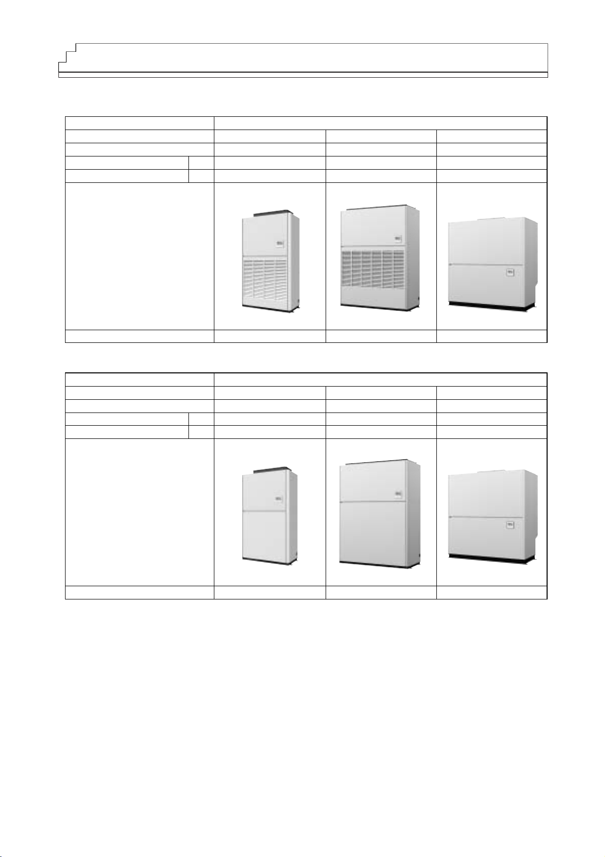
Model
PFAV-P-VM-E(-F)
PUHY-P-Y(S)HM-A
DATA BOOK
Page 2

%!. System Design
1. Outdoor Installation······································59
(1) Requirement on installation site
(2) Spacing
(3) Piping direction
(4) Weather countermeasure
2. Indoor Installation·········································68
(1) Requirement on installation site
(2) Spacing
(3) Installing the Indoor Unit
(4) Separating the indoor unit to allow for easy
transportation
(5) Internal diagram
%!!. Piping design
1. R410A Piping material ··································80
2. Piping Design ················································81
%!!!. Wiring Design
1. External wiring diagram ·······························84
(1) Power supply examples
2. Electrical work···············································86
(1) Power cable specifications
3. M-NET control ···············································87
(1) Types and maximum allowable length
of cables
(2) Switch settings and address settings
4. An Example of a System to which an MA
Remote Controller is connected··················89
5. System control ··············································92
(1) System control for the indoor units
(2) System control for the outdoor units
6. Caution for refrigerant leakage····················98
!. General Cautions
1. Indoor Unit Line-up·········································1
2. Temperature range ·········································2
3. Notes on selecting equipments·····················3
(1) Notes on using the Fresh Air Intake type units
!!. Indoor Unit
1. Specifications··················································5
(1) Standard type
(2) Fresh air intake type
2. External dimensions·······································7
(1) Standard type
(2) Fresh air intake type
3. Center of gravity ···········································13
4. Electrical wiring diagram ·····························14
5. Sound Pressure Levels ································18
6. Vibration levels ·············································21
7. Fan characteristic curves·····························22
8. Optional parts················································41
!!!. Outdoor Unit
1. Specifications················································42
2. External dimensions·····································43
3. Center of gravity ···········································47
4. Electrical wiring diagram ·····························48
5. Sound Pressure Levels ································49
6. Optional parts················································51
(1) Outdoor twinning kit
!%. Capacity Tables
(1) Correction by temperature························52
(2) Correction at frosting and defrosting··········54
(3) Correction by refrigerant piping length
(cooling) (heating) ·····································54
(4) Correction by indoor unit airflow rate
(cooling) (heating) ·····································55
(5) Input correction by capacity·······················56
(6) Bypass factor·············································57
%. Controller
1. Local remote controller ································58
(1) MA Remote controller
Contents
Page 3
1
!. General Cautions
1. Indoor Unit Line-up
Model type Fresh air intake type
Model size P300 P900
Nominal HP 10HP 30HP
Nominal cooling cap. *1 kW 28.0 80.0
Nominal heating cap. *2 kW 26.5 71.0
Floor standing
PFAV-P-VM-E-F
Connectable outdoor unit type PUHY-P250YHM-A PUHY-P750YSHM-A
*Nominal conditions *1,*2 are referable at the Specification sheet.
P600
20HP
56.0
50.0
PUHY-P500YSHM-A
Model type Standard type
Model size P250 P750
Nominal HP 10HP 30HP
Nominal cooling cap. *1 kW 25.0 71.0
Nominal heating cap. *2 kW 28.0 80.0
Floor standing
PFAV-P-VM-E
Connectable outdoor unit type PUHY-P250YHM-A PUHY-P750YSHM-A
*Nominal conditions *1,*2 are referable at the Specification sheet.
P500
20HP
50.0
56.0
PUHY-P500YSHM-A
Page 4
2
2. Temperature range
Cooling Heating
Indoor temperature
Wet-bulb temperature
10~25˚C [50~77˚F] (Note 1)
Dry-bulb temperature
15~28˚C [59~82˚F]
Outdoor temperature
Dry-bulb temperature
-5~43˚C [23~109˚F]
Wet-bulb temperature
-20~15.5˚C [-4~60˚F]
Standard type
Note 1. If units are operated for a long time at the dew point temperature of 23˚C [73˚F] or more, condensate may collect and drip from the indoor
units. If the units are operated under such conditions, cover the entire surface of all indoor units with insulating materials with a thickness of
between 0 and 20 mm [13/16 in.] to prevent condensate from collecting.
Cooling Heating (Note 2)
Indoor temperature
Wet-bulb temperature
15~35˚C [50~95˚F]
Dry-bulb temperature
0~20˚C [32~68˚F]
Outdoor temperature
Dry-bulb temperature
20~43˚C [68~109˚F]
Wet-bulb temperature
-4~15.5˚C [24~60˚F]
Fresh air intake type
Note 2. If the indoor intake air is pretreated to 0˚C in the primary treatment, the unit can be operated in the outdoor intake air temperature range of
between -20 and 15.5
˚CWB [-4 and 60˚FWB].
Page 5
3
(1) Notes on using the Fresh Air Intake type units
1Fresh air intake type indoor units supply pretreated outside air into the room. This type of units are not designed to
handle internal thermal load. Use other types of air conditioning units (e.g., CITY MULTI system) that are capable
of handling internal thermal load in combination with the Fresh Air Intake type units.
2The control mode is selectable between room temperature control and supply air temperature control. The default
mode is room temperature control. Install the supplied thermistor in a location that allows the sensor to measure
the representative room temperature.
·Fresh air intake type units are intended to be used in an environment at a temperature of 0˚CDB
[32
˚FDB] or above. If the units are operated in the fan mode at the temperature below 0˚C[32˚F],
condensation may form on the panel under certain conditions. Use caution so that the
condensation will not drip on appliances around the unit.
·The unit may be forced to operate in the heating mode to prevent cold draft when the return air
temperature (outside air temperature sensor reading) reaches 5
˚C[41˚F] or below. The fan will
stop during the defrost cycle and when there is a problem with the entire refrigerant systems.
The fan can be set to operate in the conditions above by making certain switch settings if a
sudden supply of cold air into the room during the heating season will not be a problem.
·Note that untreated outside air may be delivered directly into the room upon Thermo-OFF. Use
extra caution when the outside temperature is low. Direct exposure to outdoor air may have an
adverse effect on health or cause food spoilage.
·Fresh air intake type units are not equipped with a dehumidifying function. Take appropriate
measures to keep condensation from forming on the supply air grill and other parts that are
subject to condensation. Line the supply and return air ducts with insulation to prevent
condensation.
Common items
Room
temperature
control
(factory setting)
·Install the thermistor that is supplied with the indoor unit. Check that Switch 7-2 is set to OFF.
·Install the thermistor in a location that allows the sensor to measure the representative room
temperature.
·The unit will go into the forced Thermo-OFF mode when the return air dry bulb temperature
(outside air temperature sensor reading) is 21
˚C[70˚F] or below during cooling OR 20˚C[68˚F] or
above during heating.
·The settable temperature range on the remote controller is as follows: Cooling 19 - 30˚C[66 -
86
˚F]; Heating 17-28˚C[63 - 82˚F].
·Indoor temperature and humidity can fluctuate greatly depending on the outside air load.
Supply air
temperature
control
·Connect the connector of the supply air temperature sensor that is built in on the indoor unit to
the control board. Turn Switch 7-2 to ON.
·The unit will go into the forced Thermo-OFF mode and operate in the Fan mode when the return
air dry bulb temperature (outside air temperature sensor reading) is 14
˚C[57˚F] or below during
cooling OR 28
˚C[82˚F] or above during heating.
·Supply air temperature may fluctuate, depending on the temperature/humidity of the outside air
or on other operating conditions. Units may go in and out of the Thermo-ON/OFF mode when
the following conditions are met: The difference between the outside temperature and the preset
temperature is less than approximately 6
˚C[43˚F] due to excess capacity. They may change
depending on the air flow rate and preset temperature.
·Supply air temperature normally appears on the remote controller. When the unit operation is
not stable, this temperature may blink on the display and can be mistakenly interpreted as an
error. If this is a problem, change the setting to suppress the temperature display. Refer to the
section "How to use the remote controller" in the Instructions Manual for how to make the setting.
·The settable temperature range on the remote controller is as follows: Cooling 14 - 30˚C[57 -
86
˚F]; Heating 17-28˚C[63 - 82˚F].
·Depending on the air conditioning load, outside temperature, and due to the activation of
protection functions, the desired preset temperature may not always be achieved.
3
Fresh air intake type indoor unit
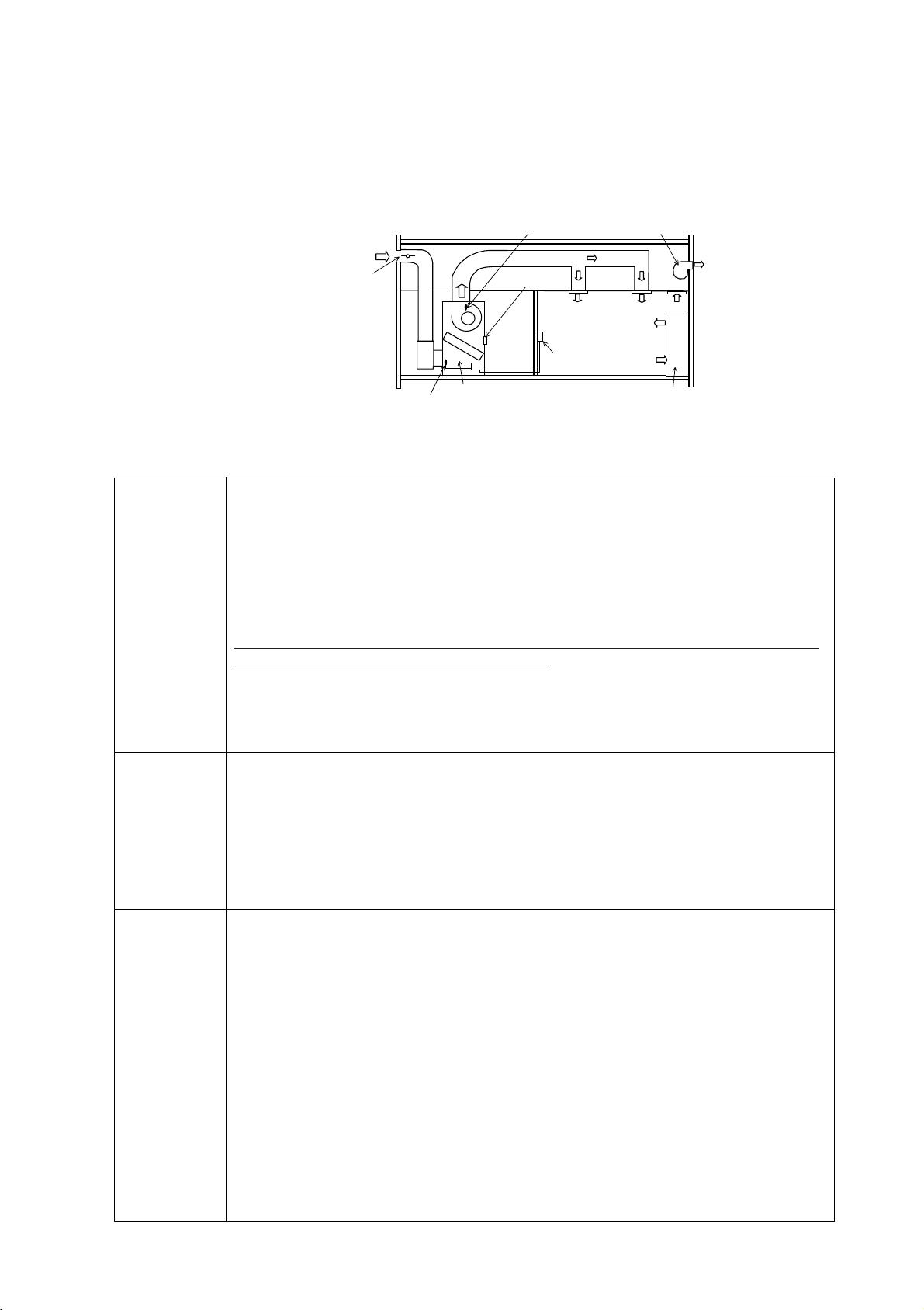
Indoor temperature controlling unit
Temperature sensor*2
Supply air temperature sensor*1
(Built in, not connected at the time of factory shipment)
(supplied)
Outside air damper
Outside air temperature sensor (built in)
Remote controller
(built in)
Discharge air
<Fresh Air Intake type sample installation>
*1 Enable to use the supply air
temperature control mode
*2 Enable to use the room
temperature control mode
3. Notes on selecting equipments
Page 6
4
4Fan control
The unit may be forced to operate in the heating mode to prevent cold draft when the return air temperature
(outside air temperature sensor reading) reaches 5
˚C[41˚F] or below. At the time of factory shipment, fan setting is
made so that the fan will stop during the defrost cycle and when there is a problem with the entire refrigerant
systems.
See below for switch settings and unit operation.
5Sample operation patterns (supply air temperature control)
The unit will follow the operation control pattern below at the nominal air flow rate and the preset temperature of
22
˚C[72˚F]. Use it only as a guide. The range changes with the air flow rate and preset temperature.
6Thermo-ON/OFF conditions (supply air temperature control)
*Settings in the shaded areas indicate factory settings.
Specifications
Forced heating
operation
Fan operation
during defrost
·Forced heating
operation disabled
·Fan stays on
when there is an
error. (The fan
stops when there
is a problem with
the fan or a
communication
error.)
·The fan turns off
when the entire
refrigerant system
is in the defrost
cycle
·Forced heating
operation enabled
·Fan turns off when
there is a problem.
·The fan turns on
during defrost
SW
SW1-7
SW3-4
Notes
When the return air temperature
reaches 5
˚C[41˚F] or below, the unit will
be forced to operate in the heating
mode to prevent cold draft regardless of
the actual operation mode setting.
If the return air temperature reaches
6
˚C[43˚F] or above, the units will
resume operation in the selected mode.
The fan will stop when there is an error,
regardless of the outside temperature.
Operation
OFF
ON
*Operating the fan during the defrost cycle can cause cold outside air to be delivered into the room, and it can also
delay normal unit operation to be resumed after the defrost cycle is completed, both of which can greatly decrease
the room temperature.
Outside temperature
[
˚F]
(
˚C)
Cooling mode
Forced
heating
operation
Cooling Thermo-OFF
Fan mode
Heating Thermo-OFF
Heating operation
Cooling operation
ControllableNote 1
Controllable
Thermo ON/OFF
Thermo ON/OFF
Supply air
temperature rises.
Forced
heating
operation
Heating mode
Fan mode
<Cooling operation>
32 41 50 59 68 77 86 95 109
051015 20 25 30 35 43
Note 1 Thermo-ON: Controllable; Thermo-OFF: Forced heating
Preset temperature
Thermo-OFF conditions
(1, 2, or 3)
Thermo-ON conditions
14
~ 30˚C [57 ~ 86˚F]
1Outside temp. < Preset temp.+0.0
2Supply air temp. < Preset temp.-2˚C lasting for consecutive 10 minutes
315 or more minutes after startup AND Supply air temp. < Preset temp.-5˚C
Supply air temp. > Preset temp +2˚C AND Return air temp. > Preset
temp.+1.5˚C, AND at least 3 minutes have passed since Thermo-OFF
<Heating operation>
Preset temperature
Thermo-OFF conditions
(1, 2, or 3)
Thermo-ON conditions
17
~ 28˚C [68 ~ 82˚F]
1Outside temp. < Preset temp.+0.0
2Supply air temp.> Preset temp.+5˚C lasting for consecutive 10 minutes
315 or more minutes after startup and Supply air temp. > Preset temp.+10˚C
Supply air temp. < Preset temp.-2˚C AND Return air temp. < Preset temp. -
1.5˚C AND at least three minutes have passed since Thermo-OFF
Page 7
1. Specifications
(1) Standard type
5
!!. Indoor Unit
Model Name
Indoor PFAV-P250VM-E
Outdoor
PUHY-P250YHM-A
Cooling
Heating
Cooling
Heating
System capacity
kW
kW
kW
kW
Cooling
Heating
25.0 (Maximum28.0)
28.0 (Maximum 31.5)
System Power input
7.46 / 7.53
8.27 / 8.34
System current
A
A
14.5-13.8-13.3 / 13.4-12.8-12.3
15.8-15.0-14.4 / 14.7-14.0-13.4
Power source 3-phase 4-wire 380-400-415V (50Hz / 60Hz)
Power input kW 0.82 / 0.89
Current A 3.4-3.2-3.1 / 2.3-2.2-2.1
Fan
Type x Quantity Sirocco fan x 2
Airflow rate
m /min
3
90
External static pressure Pa 30 / 90
Motor output kW 2.2
Refrigerant R410A
External finish
External dimension mm
1748(H) x 1200(W) x 485(D)
Protection devices Fan Over current protection
Refrigerant
piping diameter
mm
mm
Liquid pipe
9.52 Brazed (12.7 for over 90m)
Gas pipe 22.2 Brazed
Refrigerant piping allowable length
m 165
Sound pressure level dB(A) 55
Heat exchanger Cross fin (aluminum plate fin and copper tube)
Air filter Synthetic fiber unwoven cloth filter
Net weight kg 156
Operating
temperature range
Cooling
Heating
PFAV-P500VM-E
PUHY-P500YSHM-A
(PUHY-P250YHM-A x 2,
CMY-Y100VBK2)
50.0 (Maximum56.0)
56.0 (Maximum 63.0)
17.85 / 18.84
17.00 / 17.99
32.3-30.7-29.6 / 32.6-31.0-29.9
30.8-29.3-28.2 / 31.1-29.6-28.5
2.37 / 3.36
6.2-5.9-5.7 / 6.5-6.2-6.0
Sirocco fan x 1
180
30 / 130
5.5
R410A
Galvanized steel plate (with polyester coating)
MUNSELL 5Y 8 / 1 or similar
1899(H) x 1420(W) x 635(D)
Over current protection
15.88 Brazed
28.58 Brazed
165
59 / 62
265
Indoor: 10 to 25 degCWB
Indoor: 15 to 28 degCDB
(Outdoor: -5 to 43 degCDB)
(Outdoor: -20 to 15.5 degCWB)
PFAV-P750VM-E
PUHY-P750YSHM-A
(PUHY-P350YHM-A +
PUHY-P400YHM-A,
CMY-Y200VBK2)
71.0 (Maximum 80.0)
80.0 (Maximum 90.0)
26.33 / 27.40
23.93 / 25.00
48.1-45.7-44.1 / 47.5-45.1-43.5
43.4-41.2-39.8 / 42.8-40.6-39.2
4.30 / 5.37
10.9-10.4-10.0 / 10.3-9.8-9.4
Sirocco fan x 1
260
100 / 310
7.5
R410A
1860(H) x 1750(W) x 1064(D)
Over current protection
19.05 Brazed
34.93 Brazed
165
65
PP Honeycomb fabric filter
459
Note
1. Cooling / Heating capacity indicates the value at operation under the following conditions.
(Cooling) Indoor: 27degCDB / 19degCWB, Outdoor: 35degCDB
(Heating) Indoor: 20degCDB, Outdoor: 7degDB / 6degCWB
Pipe length: 7.5m, Height difference: 0m
2. The sound pressure level is measured in an anechoic room.
3. Long period operation in a high temperature and humidity atmosphere (dew point of 23
˚C or more) may cause
condensation to form in the indoor unit.
Works not included: Installation / foundation work, electric connection work, duct work, insulation work,
the power source switch and other items are not specified in the specifications.
Page 8
6
Model Name
Indoor PFAV-P300VM-E-F
Outdoor
PUHY-P250YHM-A
Cooling
Heating
Cooling
Heating
System capacity
kW
kW
kW
kW
Cooling
Heating
28.0 (Maximum 33.5)
26.5 (Maximum 28.0)
System Power input
6.73 / 6.72
7.57 / 7.56
System current
A
A
12.6-11.9-11.5 / 12.2-11.5-11.1
14.0-13.3-12.8 / 13.6-12.9-12.4
Power source 3-phase 4-wire 380-400-415V (50Hz / 60Hz)
Power input kW 0.37 / 0.36
Current A 1.9-1.8-1.7 / 1.5-1.4-1.3
Fan
Type x Quantity Sirocco fan x 2
Airflow rate
m /min
3
45
External static pressure Pa 80
Motor output kW 1.5
Refrigerant R410A
External finish
External dimension mm
1748(H) x 1200(W) x 485(D)
Protection devices Fan Over current protection
Refrigerant
piping diameter
mm
mm
Liquid pipe
9.52 Brazed (12.7 for over 90m)
Gas pipe 22.2 Brazed
Refrigerant piping allowable length
m 165
Sound pressure level dB(A) 48.5
Heat exchanger Cross fin (aluminum plate fin and copper tube)
Air filter Synthetic fiber unwoven cloth filter
Net weight kg 151
Operating
temperature range
Cooling
Heating
PFAV-P600VM-E-F
PUHY-P500YSHM-A
(PUHY-P250YHM-A x 2,
CMY-Y100VBK2)
56.0 (Maximum 67.0)
50.0 (Maximum 56.0)
14.69 / 15.05
15.43 / 15.79
26.1-24.9-24.0 / 26.2-25.0-24.0
27.4-26.1-25.1 / 27.5-26.2-25.1
0.90 / 1.26
2.9-2.8-2.8 / 3.0-2.9-2.8
Sirocco fan x 1
90
110 / 170
2.2
R410A
Galvanized steel plate (with polyester coating)
MUNSELL 5Y 8 / 1 or similar
1899(H) x 1420(W) x 635(D)
Over current protection
15.88 Brazed
28.58 Brazed
165
50 / 53
248
Indoor: 15 to 35 degCWB
Indoor: 0 to 20 degCDB
(Outdoor: 20 to 43 degCDB)
(Outdoor: -4 to 15.5 degCWB)
PFAV-P900VM-E-F
PUHY-P750YSHM-A
(PUHY-P350YHM-A +
PUHY-P400YHM-A,
CMY-Y200VBK2)
80.0 (Maximum 100.0)
71.0 (Maximum 80.0)
22.54 / 22.74
21.43 / 21.63
40.5-38.5-37.1 / 39.6-37.6-36.2
38.7-36.8-35.5 / 37.8-35.9-34.6
1.77 / 1.97
5.6-5.3-5.1 / 4.7-4.4-4.2
Sirocco fan x 1
120
210 / 330
3.7
R410A
1860(H) x 1750(W) x 1064(D)
Over current protection
19.05 Brazed
34.93 Brazed
165
57
PP Honeycomb fabric filter
437
Note
1. Cooling / Heating capacity indicates the value at operation under the following conditions.
(Cooling) Indoor,Outdoor: 33degCDB / 28degCWB
(Heating) Indoor,Outdoor: 7degDB / 3degCWB
Pipe length: 7.5m, Height difference: 0m
2. The sound pressure level is measured in an anechoic room.
3. The indoor intake air temperature should be kept more than 0 degC.
4. At factory setting, the fan temporary stops in defrosting. Change DIP SW for fan to operate in defrosting.
5. Indoor temperature and humidity cannnot be controlled with Fresh air intake type.
Works not included: Installation / foundation work, electric connection work, duct work, insulation work,
the power source switch and other items are not specified in the specifications.
(2) Fresh air intake type
Page 9
•PFAV-P250VM-E
7
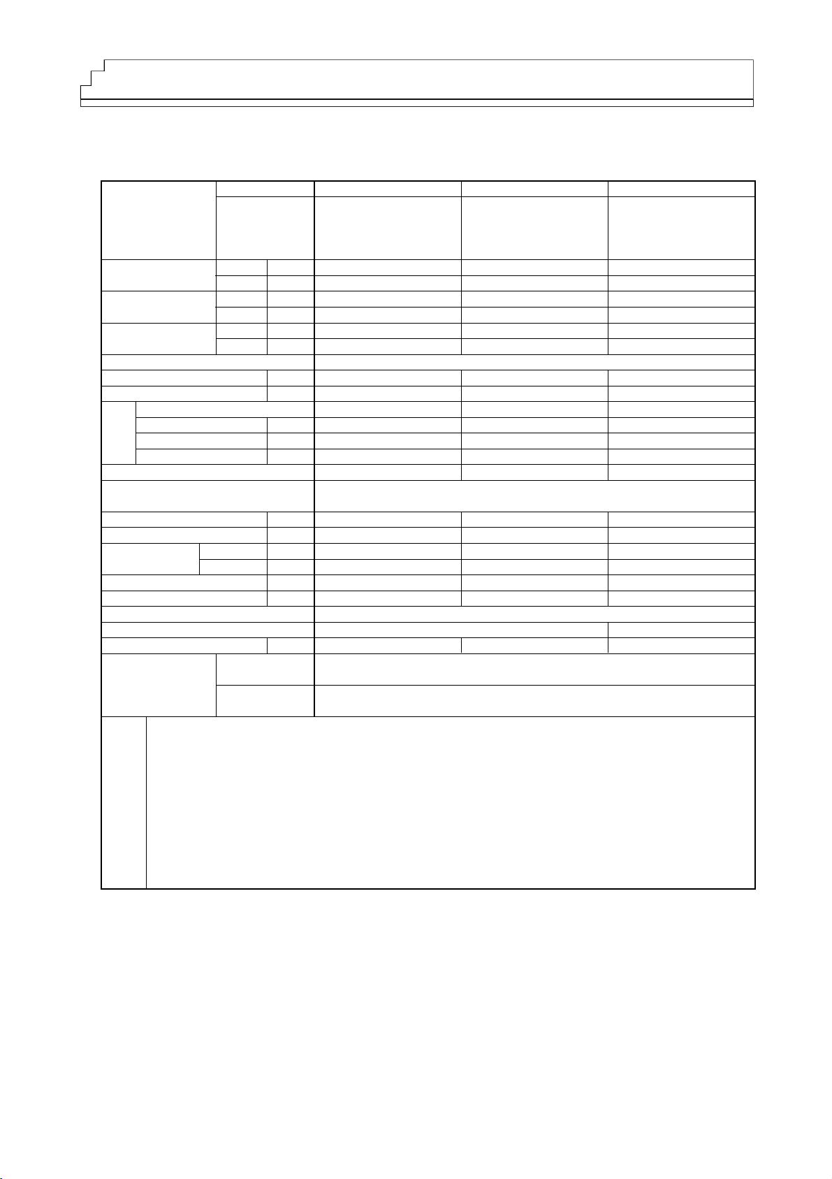
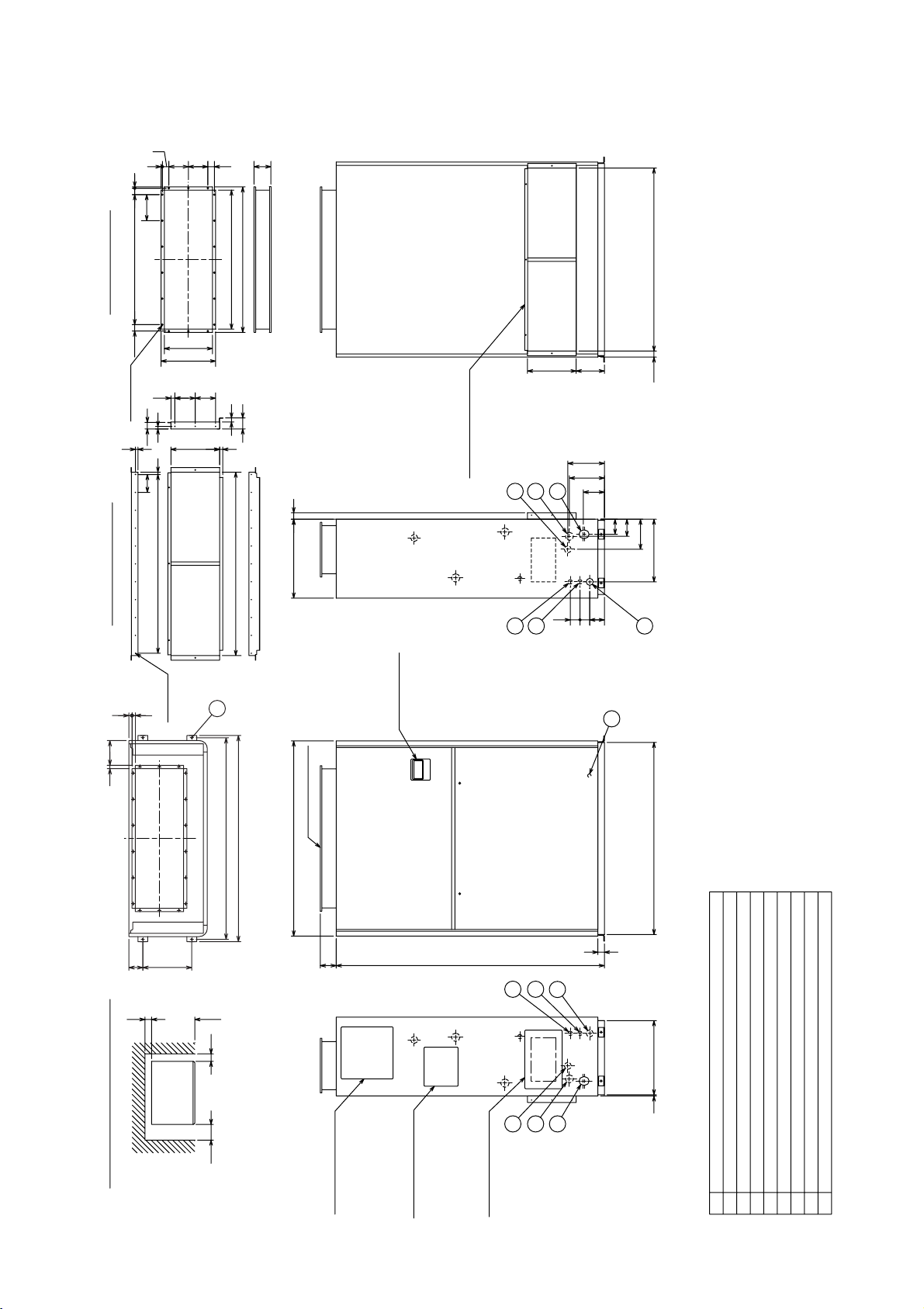
2. External dimensions
(1) Standard type
30
20 19
152
300
85
8
160
Indoor unit
8
8
800
Service panel
Service panel
Service panel
(Service for fan pulley)
(Service for motor pulley)
Supply air duct flange
1650
Required space for service and air flow
50
500 100
Minimum necessary dimension.
385
105
92
7 456
215
130
40
40
39.5
39.5
2
1
3
6
5
4
60
60
90
40
485
18-ø3Holes
104
120 120
336
296
7
Rear air inlet
Supply air duct flange
Front air inlet
5
6
4
3
1
2
835
895
160X5=800
1200
1234
1262
1182
225
185
Remote controller
98
Secure the proper space for
installation work such as
piping and wiring separately.
Notes 1.Be sure to wire the transmission line and power line separately.
2.When the room in which the unit is installed is airtight,
the pressure in the room may become negative.
This may result in problems such as the door to becoming difficult
to open etc.
To avoid these kinds of problems please ensure that a small amount of
air is able to ventilate the room via some kind of small hole or vent.
Earth terminal(installed in the control box)···M5
Wiring hole(The outdoor unit connection,Transmission line)······ø27
For mounting anchor bolt 4-ø12 Holes
Wiring hole······ø27
Power supply wiring hole······ø43
Drain hole······Rc 1
Refrigerant pipe<Liquid>···ø9.52 brazed
Refrigerant pipe<Gas>···ø22.2 brazed
DesignationNO.
1234567
8
Unit:mm
Page 10
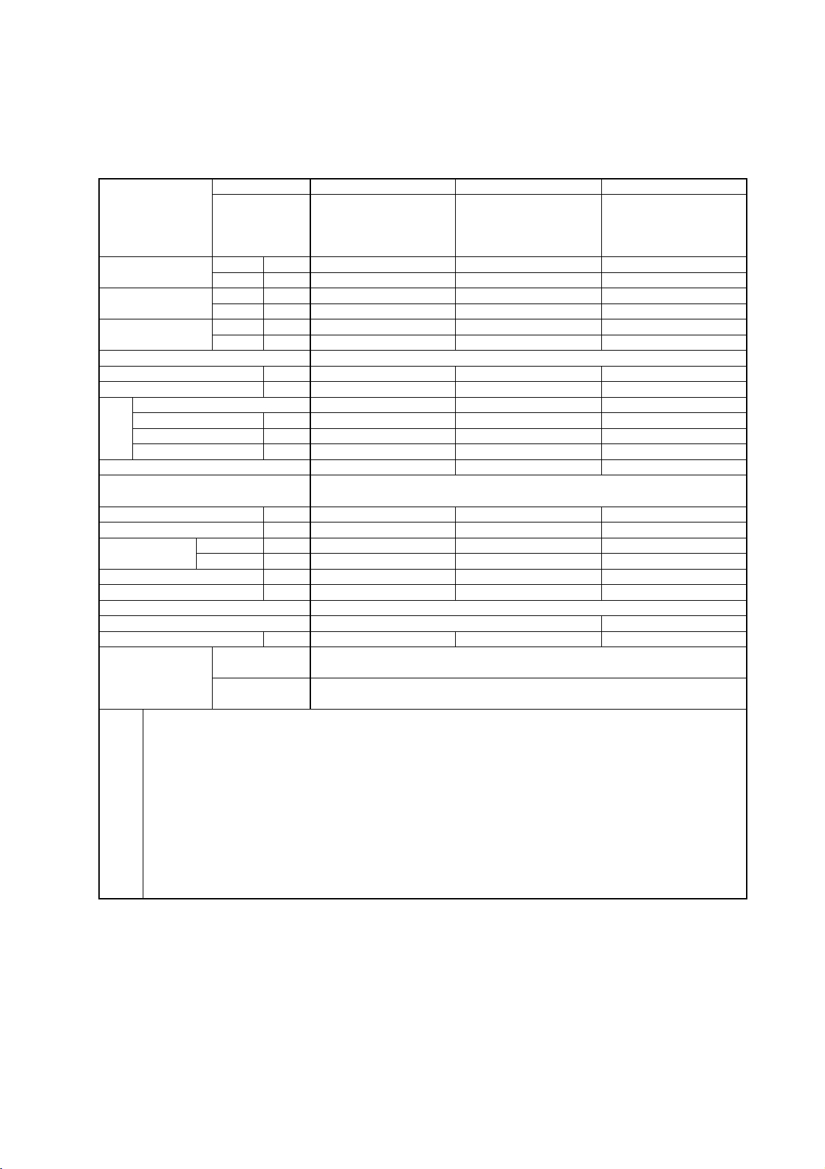
8
•PFAV-P500VM-E
8
7
6
5
4
3
2
1
NO. Designation
Refrigerant pipe<Gas>···ø28.5 brazed
Refrigerant pipe<Liquid>······ø15.88 brazed
Drain hole······Rc 1 1/4
Power supply wiring hole···ø52
Wiring hole······ø37
For mounting anchor bolt 4-ø12 Holes
Wiring hole(The outdoor unit connection,Transmission line)···ø27
Earth terminal(installed in the control box)···M5
213
Rear air inlet
Indoor unit
645
18-ø3.5Holes
Supply air duct flange
Required space for service and air flow
Secure the proper space for
installation work such as
piping and wiring separately.
Supply air duct flange
3
1
2
4
6
5
Remote controller
Front air inlet
7
Minimum necessary dimension.
247
9
484
444
9
33
20020033
118120
Notes 1.Be sure to wire the transmission line and power line separately.
2.When the room in which the unit is installed is airtight,
the pressure in the room may become negative.
This may result in problems such as the door to becoming difficult
to open etc.
To avoid these kinds of problems please ensure that a small amount of
air is able to ventilate the room via some kind of small hole or vent.
169
100
92
635
49
530
6070
100
100
50
1000
1420
1478
1450
1213
1253
247X5=1235
1850
40
9602
1398
296
20
82
90
20 21
440
8
Unit:mm
Page 11

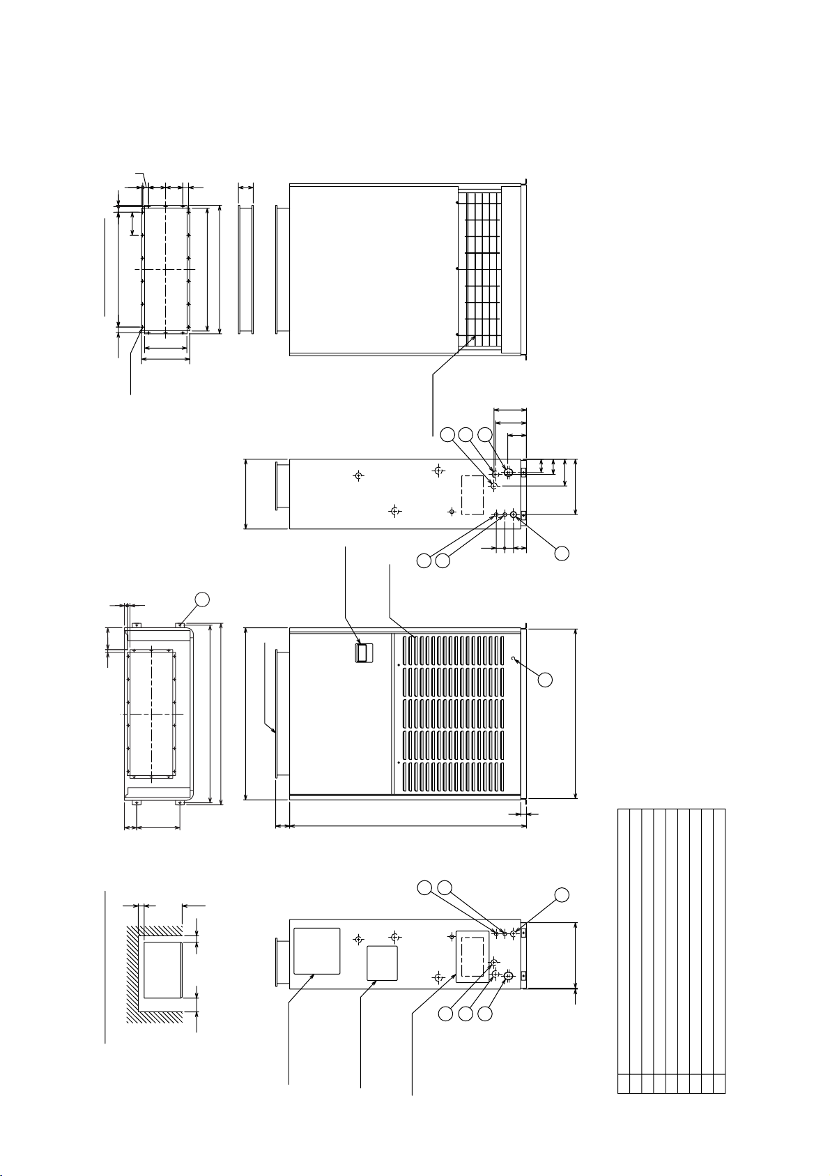
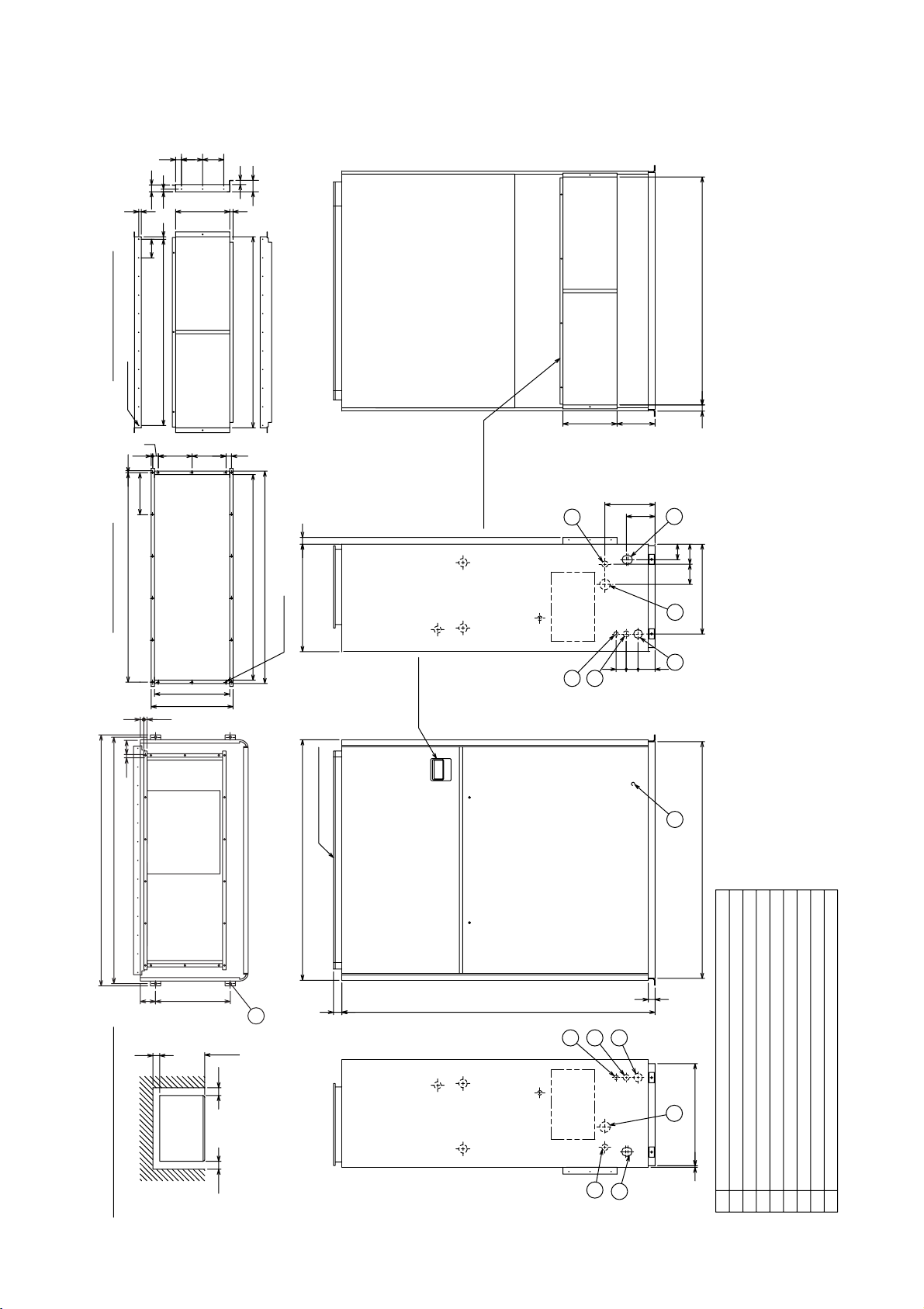
9
•PFAV-P750VM-E
Minimum necessary dimension.
Indoor unit
Required space for service and air flow
Secure the proper space for installation work
such as piping and wiring separately.
Please secure the size of *sign when you serve
the air filter from the right side of the main body.
Notes 1.Please secure the size in the service space of the air filter(*sign)
for a left side or a right side of the unit.
2.Be sure to wire the transmission line and power line separately.
3.When the room in which the unit is installed is airtight,
the pressure in the room may become negative.
This may result in problems such as the door to becoming difficult
to open etc.
To avoid these kinds of problems please ensure that a small amount of
air is able to ventilate the room via some kind of small hole or vent.
4.Connect by using the connecting pipes that are supplied.
(Size on inside)
(Size on inside)
2
5
6
3
4
(Size on inside)
8
7
2
1
5
6
Air filter
12
5
6
1
(Size on inside)
47656439606
30
12
476
110X4=440
18
20-ø4.3Holes
606
110X4=440 83
42
750 500
1000
400
580100
875
810
740
450
220
150
112
493
994
741
70
35
10
1212
106
200X5=1000
(599)
106
300
195
71525
30
*750(106)
1460
200X7=1400
(146)*750
30
200
10
(50)
1722 50
1045
976
300
1830
30
61575
1822
1774
1750
140100
490
220
150
191
261
Supply air duct flange
28-ø4.3Holes
note:1
Air filter service space
Remote controller
Supply air duct flange
Drain hole<Lower side>······Rc 1
Earth terminal(installed in the control box)······M5
Wiring hole(The outdoor unit connection,Transmission line)······ø38
For mounting anchor bolt 4-ø15 Holes
Wiring hole······ø62
Drain hole<Upper part>······Rc 1 1/4
Refrigerant pipe<Liquid>···ø19.05 brazed
Refrigerant pipe<Gas>···ø34.93 brazed
DesignationNO.
1234567
8
Unit:mm
Page 12
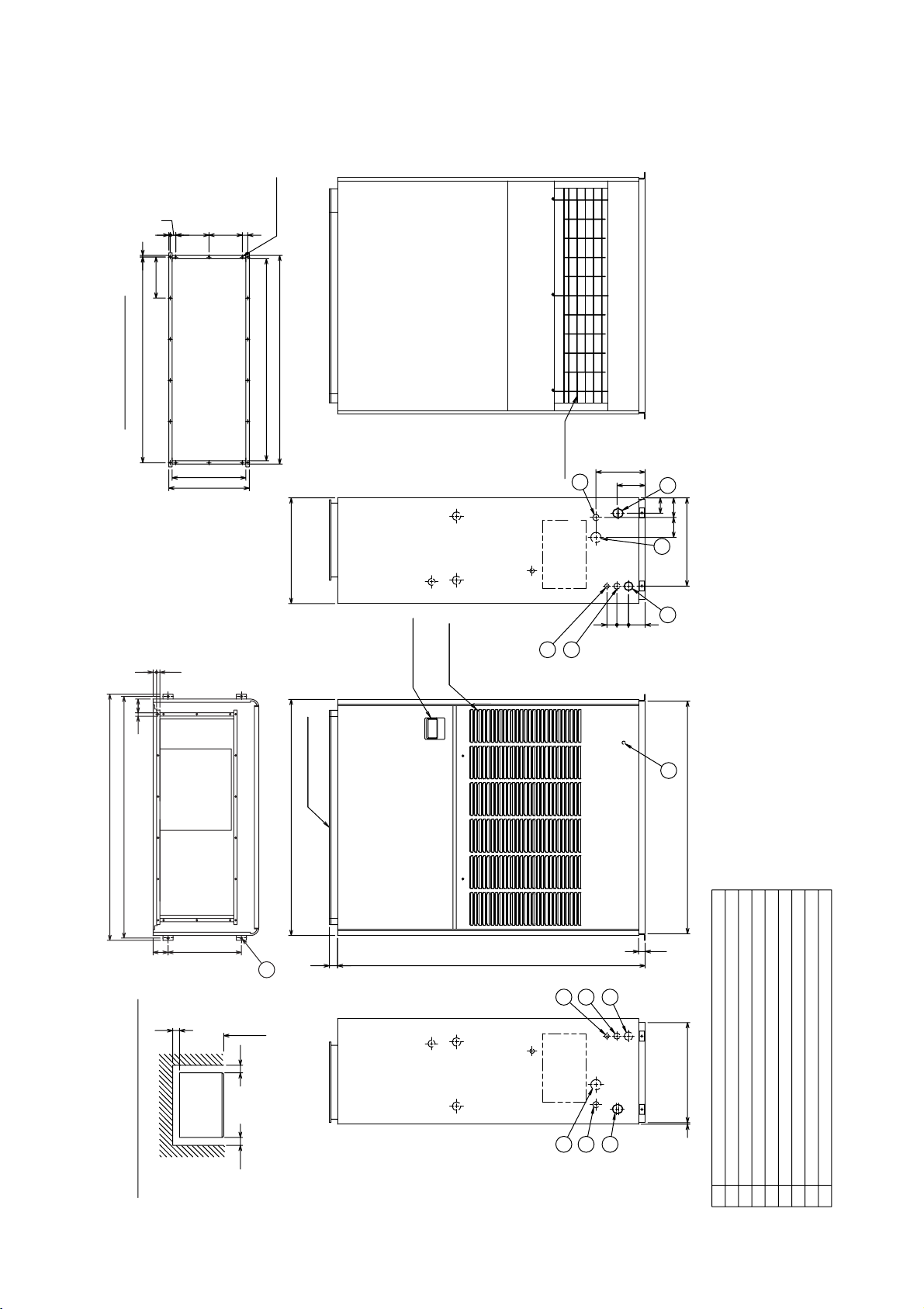
10
8
7
6
5
4
3
2
1
NO. Designation
Refrigerant pipe<Gas>
···ø
22.2 brazed
Refrigerant pipe<Liquid>
···ø
9.52 brazed
Drain hole
········
Rc 1
Power supply wiring hole
·······ø
43
Wiring hole
·····ø
27
For mounting anchor bolt 4-
ø
12 Holes
Wiring hole(The outdoor unit connection,Transmission line)
······ø
27
Earth terminal(installed in the control box)
···
M5
(1126)
37
Indoor unit
Notes 1.Be sure to wire the transmission line and power line separately.
2.When the room in which the unit is installed is airtight,
the pressure in the room may become negative.
This may result in problems such as the door to becoming difficult
to open etc.
To avoid these kinds of problems please ensure that a small amount of
air is able to ventilate the room via some kind of small hole or vent.
8
8
(Service for thermistor)
(Service for motor pulley)
(Service for fan pulley)
Service panel
Secure the proper space for
installation work such as
piping and wiring separately.
300173
Rear air inlet duct flange
40
Rear air inlet duct flange
67
26
125125
15
110
30020
15
28-
ø
3 Holes
1126
Supply air duct flange
98
Remote controller
185
225
1182
1200
160X5=800
895
855
2
1
3
4
6
5
Supply air duct flange
Service panel
Service panel
7
296
336
120120104
18-
ø
3.5 Holes
485
40
90
60
60
4
5
6
3
1
2
160
39.539.5
40
40
130
215
4567
92
105
385
Minimum necessary dimension.
100500
50
Required space for service and air flow
1650
13110X10=1100
25
40
800
30
20 19
152
300
85
8
1234
1262
•PFAV-P300VM-E-F
Unit:mm
(2) Fresh air intake type
Page 13
11
•PFAV-P600VM-E-F
Earth terminal(installed in the control box)
···
M5
Wiring hole(The outdoor unit connection,Transmission line)
······ø
27
For mounting anchor bolt 4-
ø
12 Holes
Wiring hole
·····ø
37
Power supply wiring hole
·······ø
52
Drain hole
········
Rc 1 1/4
Refrigerant pipe<Liquid>
···ø
15.88 brazed
Refrigerant pipe<Gas>
···ø
28.5 brazed
DesignationNO.
1 2 3 4 5 6 7
8
2
3
1
7
4
5
6
Supply air duct flange
Remote controller
Rear air inlet duct flange
2
3
14
6
5
37
(1346)
118120
Supply air duct flange
Rear air inlet duct flange
Required space for service and air flow
Minimum necessary dimension.
Secure the proper space for
Indoor unit
installation work such as
piping and wiring separately.
Notes 1.Be sure to wire the transmission line and power line separately.
2.When the room in which the unit is installed is airtight,
the pressure in the room may become negative.
This may result in problems such as the door to becoming difficult
to open etc.
To avoid these kinds of problems please ensure that a small amount of
air is able to ventilate the room via some kind of small hole or vent.
18-
ø
3.5 Holes
32-
ø
3 Holes
40
1000
320224
49
67
26
125125
15
110
32020 15
1346
13
12X110=1320
35
40
9
9
169
100
92
635
530
6070100
100
50
1420
1478
1450
1213
1253
20020033
33
444
484
247
247X5=1235
1850
40
9 602
1398
296
8
20
21
8220
90
440
Unit:mm
Page 14
12
•PFAV-P900VM-E-F
Minimum necessary dimension.
Indoor unit
Required space for service and air flow
Secure the proper space for installation work
such as piping and wiring separately.
Please secure the size of *sign when you serve
the air filter from the right side of the main body.
Notes 1.Please secure the size in the service space of the air filter(*sign)
for a left side or a right side of the unit.
2.Be sure to wire the transmission line and power line separately.
3.When the room in which the unit is installed is airtight,
the pressure in the room may become negative.
This may result in problems such as the door to becoming difficult
to open etc.
To avoid these kinds of problems please ensure that a small amount of
air is able to ventilate the room via some kind of small hole or vent.
4.Connect by using the connecting pipes that are supplied.
(Size on inside)
(Size on inside)
2
5
6
3
4
(Size on inside)
8
7
2
1
5
6
Air filter
12
5
6
1
(Size on inside)
47656439606
30
12
476
110X4=440
18
20-ø4.3Holes
606
110X4=440 83
42
750 500
1000
400
580100
875
810
740
450
220
150
112
493
994
741
70
35
10
1212
106
200X5=1000
(599)
106
300
195
71525
30
*750(106)
1460
200X7=1400
(146)*750
30
200
10
(50)
1722 50
1045
976
300
1830
30
61575
1822
1774
1750
140100
490
220
150
191
261
Supply air duct flange
28-ø4.3Holes
note:1
Air filter service space
Remote controller
Supply air duct flange
Drain hole<Lower side>······Rc 1
Earth terminal(installed in the control box)······M5
Wiring hole(The outdoor unit connection,Transmission line)······ø38
For mounting anchor bolt 4-ø15 Holes
Wiring hole······ø62
Drain hole<Upper part>······Rc 1 1/4
Refrigerant pipe<Liquid>···ø19.05 brazed
Refrigerant pipe<Gas>···ø34.93 brazed
DesignationNO.
1234567
8
Unit:mm
Page 15

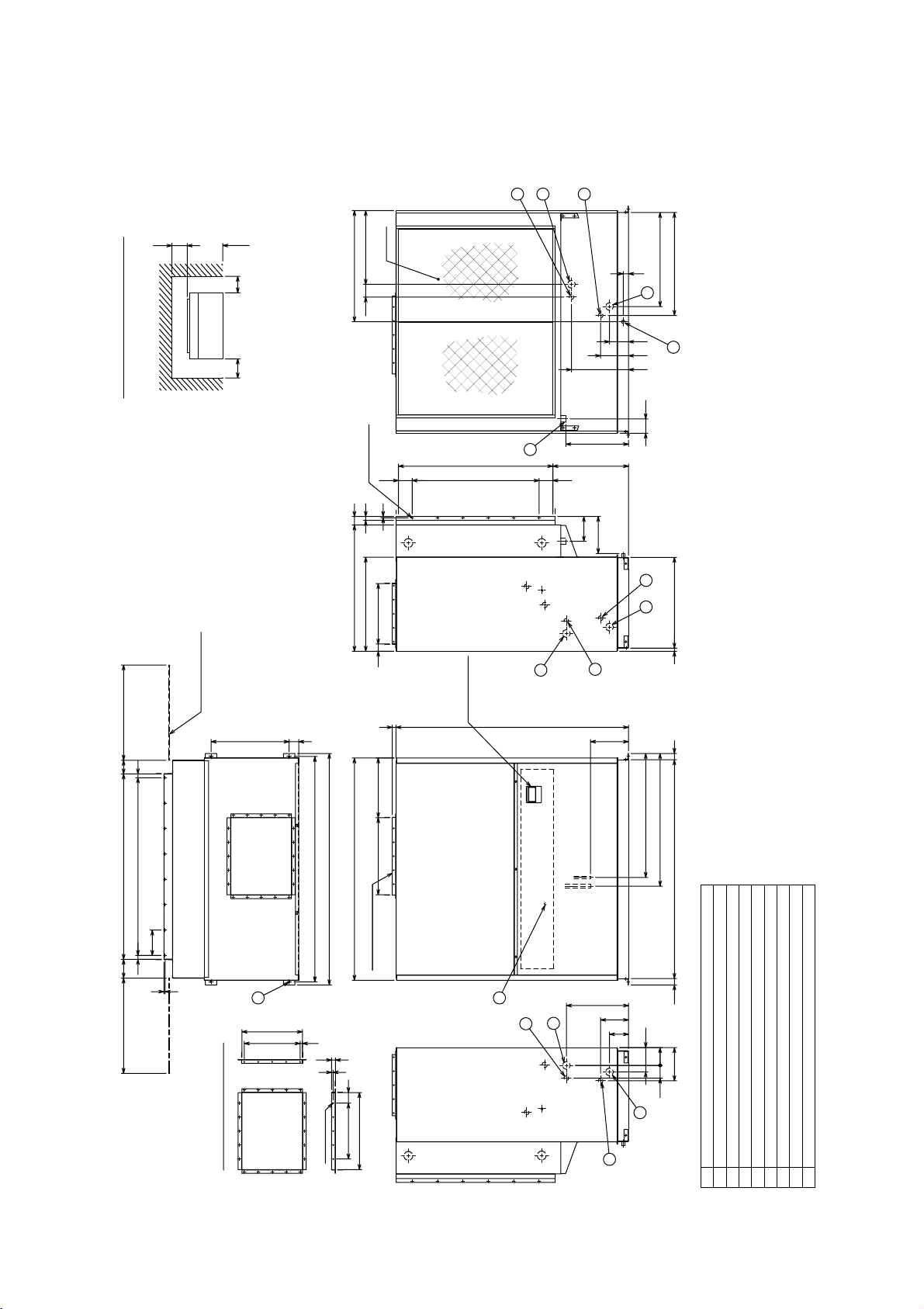
13
3. Center of gravity
(1) Indoor unit
•PFAV-P250,P500 (P300-F, P600-F)
•PFAV-P750 (P900-F)
W
X
Y
Z
L
445
615
835
1774
X
WModel L YXZ
PFAV-P250VM-E
PFAV-P500VM-E
PFAV-P300VM-E-F
PFAV-P600VM-E-F
1234
1450
1234
1450
300
440
300
440
573
651
573
667
156
217
161
219
835
1144
825
1113
XModel
PFAV-P750VM-E
PFAV-P900VM-E-F
1020
Page 16
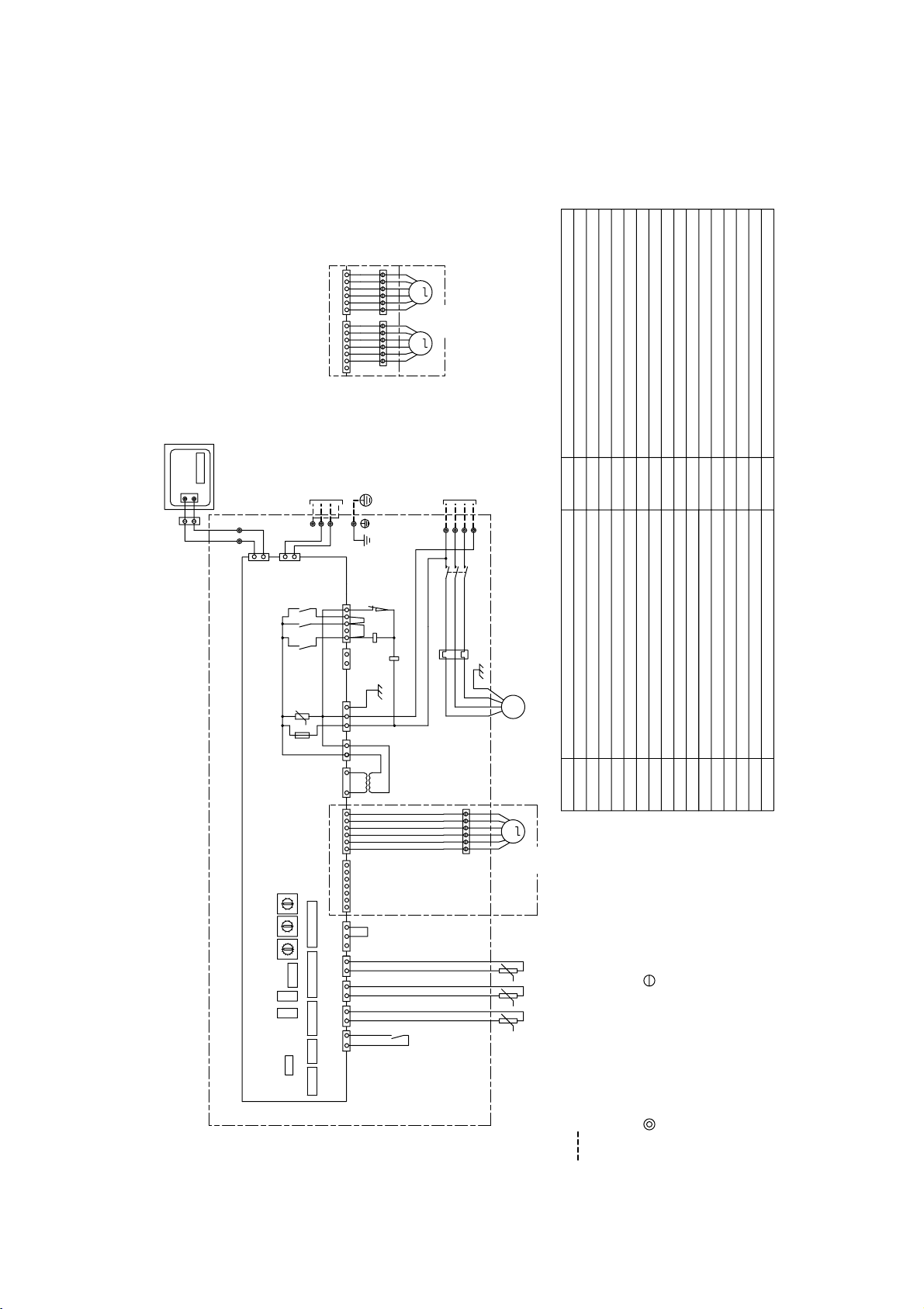
14
•PFAV-P250, 500VM-E
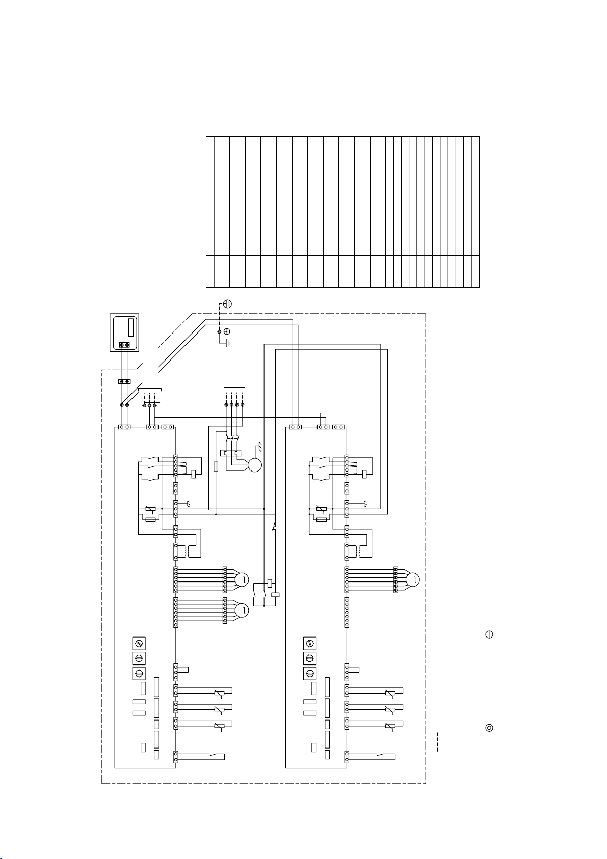
4. Electrical wiring diagram
(1) Standard type
Terminal bed(Indoor unit)
Liquid crystal monitor
Remote controller board
TB6
LCD
R.B.
Remote controller
Inside section of control box
Indoor/Outdoor
transmission line
Power supply
3N~
380/400/415V
50/60Hz
SWE
SWC
SW8
SW5
TH21 Thermistor(Supply air temp. detection)
Thermistor(Piping temp. detection/liquid)TH22
TH23
Auxiliary relay(Fan)X4
Switch
SW4
SW3
SW2
SW11
SW12
SW14
SW1
SW7
Thermistor(Piping temp. detection/gas)
(1st digit address set)
Switch
(Connection No. set)Switch
(For model selection)Switch
(For mode selection)Switch
(For capacity code)Switch
(For mode selection)Switch
(For model selection)Switch
(For four stages demand selection)Switch
(For trial run)Switch
(For mode selection)Switch
(For trial run of fan)Switch
CN28 Connector(Fan failure)
Over current relay(Fan motor)
Contactor (Fan motor)
Electronic linear expan. valve 1
Transformer
Varistor
Fuse<6.3A>
MA Remote controller terminal bed
Transmission terminal bed
Power source terminal bed
Fan motor
Symbol
Symbol explanation
TB15
51F
52F
LEV1
T
ZNR
F
TB5
TB2
M
Connector(Defrost output)CN33
NameSymbol
LEV2 Electronic linear expan. valve 2
(2nd digit address set)
Name
2
313 13
CN33
T
52F
ZNR
F
X06
1
1
1
CNT
CND
X4
2
1
2
11
M
CN28
3
2
1
CN20
CN21
321
X4
CN29
CN3T
CN60
CN31
R.B.
TB6
LCD
TB5
(Shield)
2
1
1
3
51F
52F
X05
X04
7
2
1
CN3A
M1
S
M2
35
CN90
CN2M
Indoor controller board
1
2
51F
CN7V
9
5
TH23TH22TH21
TB15
L2L1L3
TB2
1234567
123456
123456
LEV1
M
3
~
Fan motor
1
2
3
4
5
6
7
8
0
8
7
6
5
4
3
2
1
0
9
1
2
3
4
5
6
7
8
9
0
9
A
B
C
D
E
F
SW11
SW12
SW14 SW8 SW5 SWC
SWE
SW1 SW3 SW2 SW7 SW4
N
❈ P250
❈
P500
1234567
LEV1
654321
CN7V CN60
M
LEV2
654321 654321
M
t˚t˚t˚
Earth
U
Note: 1. (Heavy dotted line):Field wiring
2. Have all electric work done by a licensed electrician
according to the local regulations.
3. Earth leakage circuit breaker should be set up on the
wiring of the power supply.
4. Mark indicates terminal bed, connector.
5. Auto-restart function from power failure can be turned
on by setting SW1-9 dip switch to its ON position.
(Note:This function is not set to ON from the factory.)
Page 17
15
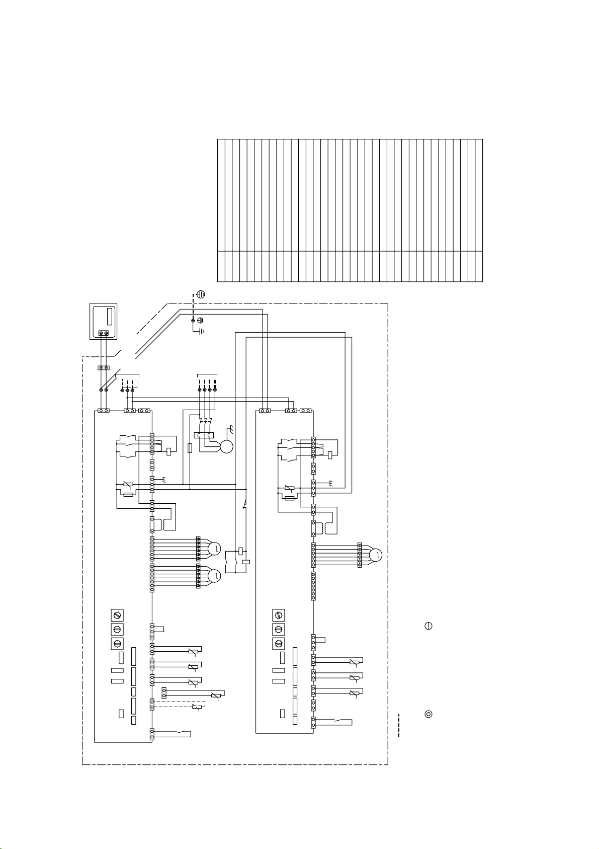
•PFAV-P750VM-E
X1,X2,X4
Fuse<6.3A>F1
F Fuse<6.3A>
Contactor (Fan motor)
Thermistor(Supply air temp. detection)TH21
Electronic linear expan. valve 3LEV3
Electronic linear expan. valve 2LEV2
Symbol Name
Fan motor
Electronic linear expan. valve 1
Remote controller board
Liquid crystal monitor
Power source terminal bed
Transmission terminal bed
Varistor
Transformer
Symbol explanation
MA Remote controller terminal bed
M
R.B.
LCD
TB2
TB5
TB15
ZNR
T
LEV1
Contactor (Fan motor)52F
51F Over current relay(Fan motor)
CN33 Connector(Defrost output)
Thermistor(Piping temp. detection/gas)
Thermistor(Piping temp. detection/liquid)
Switch (For model selection)SW7
SW1
SW14
SW12
SW11
SW4
SW5
SW8
Switch (For model selection)
Switch (Connection No. set)
Switch (For capacity code)
Switch (For four stages demand selection)
Switch (For mode selection)
Switch (2nd digit address set)
Switch (1st digit address set)
SW3
SW2
Switch (For mode selection)
TH22
TH23
TB6 Terminal bed(Indoor unit)
CN28 Connector(Fan failure)
SWE
SWC
Switch (For trial run)
Switch (For trial run of fan)
Switch (For mode selection)
Earth
Inside section of control box
LEV3
LEV2 LEV1
(Shield)
N
Indoor controller board No.2
31
123456
SW14
SW12
SW11
Indoor/Outdoor
transmission line
M1
S
M2
2
1
CN2M
CNP
1
3
CN28
12
X4
t˚ t˚ t˚
TH21 TH22 TH23
2121
CN21
21
CN20
CN29
CN3A
2
1
CN2M
CNP
1
3
SW8SW5
13 13
CN33
ZNR
F
X06
X05
X04
7135
CND
CN90
95
U
1
T
CN3T
31
CNT
2345
U
6
M
7
CN7V
SWE
t˚ t˚
50/60Hz
380/400/415V
9
TH23
CN29
21
t˚
M
654321
SW4
X4
X2
52F
X1
F1
SW7
SW2
654321
CN60
X2
3
1
321
CN31
SW11
SW12
SW14
CN7V
6543217
SW3 SW1
SWC
51F
CN31
123
Indoor controller board No.1
CN90
CND
CNT
CN60
CN20
SW5
1
1
5
2
2
3
1
3
4
1
56
L1
L2
TH21
SW2
SW7
1
3
CN3T
CN21
TH22
SWC
SW3
CN3A
1
2
SW4
Power supply
3N~
7
X04
X05
X06
F
ZNR
L3
52F
123456
T
CN33
31
CN28
3
1
1
2
M
M
31
3
12
12
X1
3~
X4
51F
SW1
SW8
SWE
5
TB2
1
2
3
4
5
6
7
8
0
9
A
B
C
D
E
F
8
7
6
5
4
3
2
1
0
9
1
2
3
4
5
6
7
8
9
0
TB5
0
9
8
7
6
5
4
3
2
1
9
0
1
2
3
4
5
6
7
8
F
E
D
C
B
A
9
0
8
7
6
5
4
TB15
Remote controller
LCD
TB6
R.B.
3
2
1
Note: 1. (Heavy dotted line):Field wiring
2. Have all electric work done by a licensed electrician according to
the local regulations.
3. Earth leakage circuit breaker should be set up on the wiring of the
power supply.
4. Mark indicates terminal bed, connector.
5. To enable the "auto recovery after power failure" function, set
SW1-9 of both No. 1 and No. 2 circuit boards to ON.
(Factory setting: OFF)
Page 18
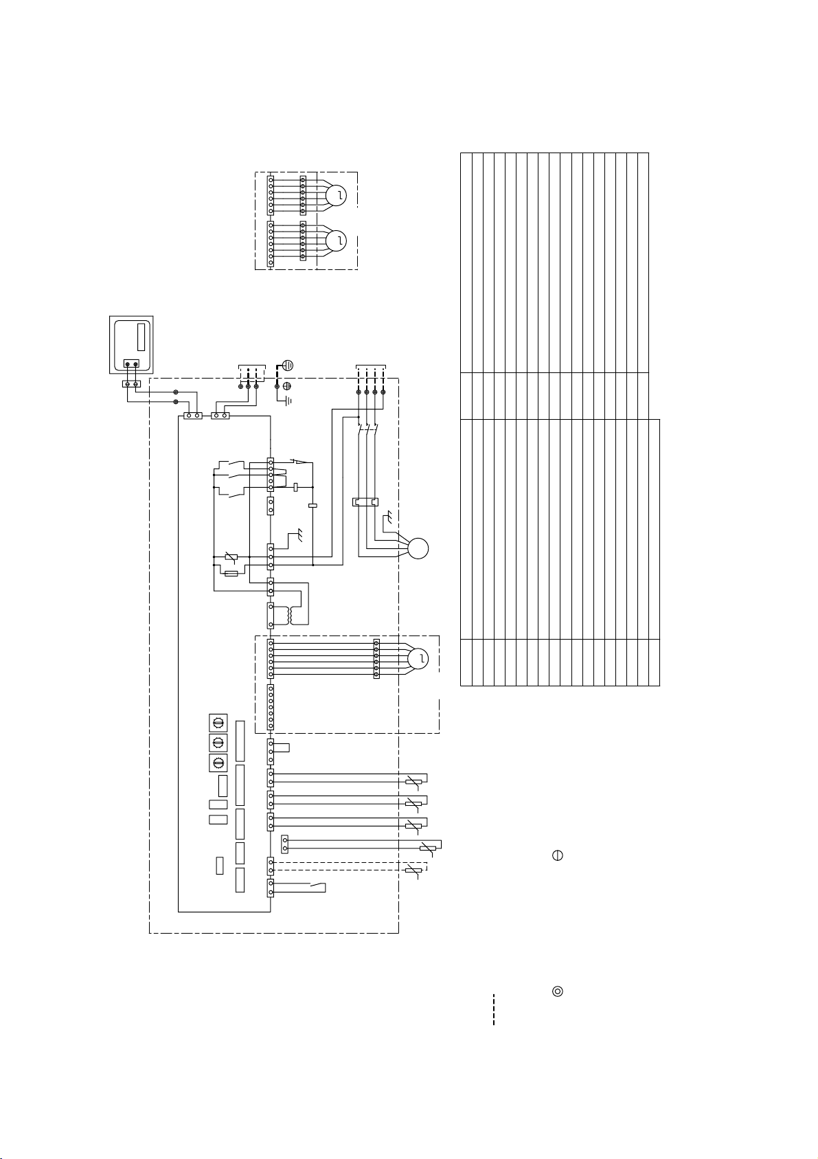
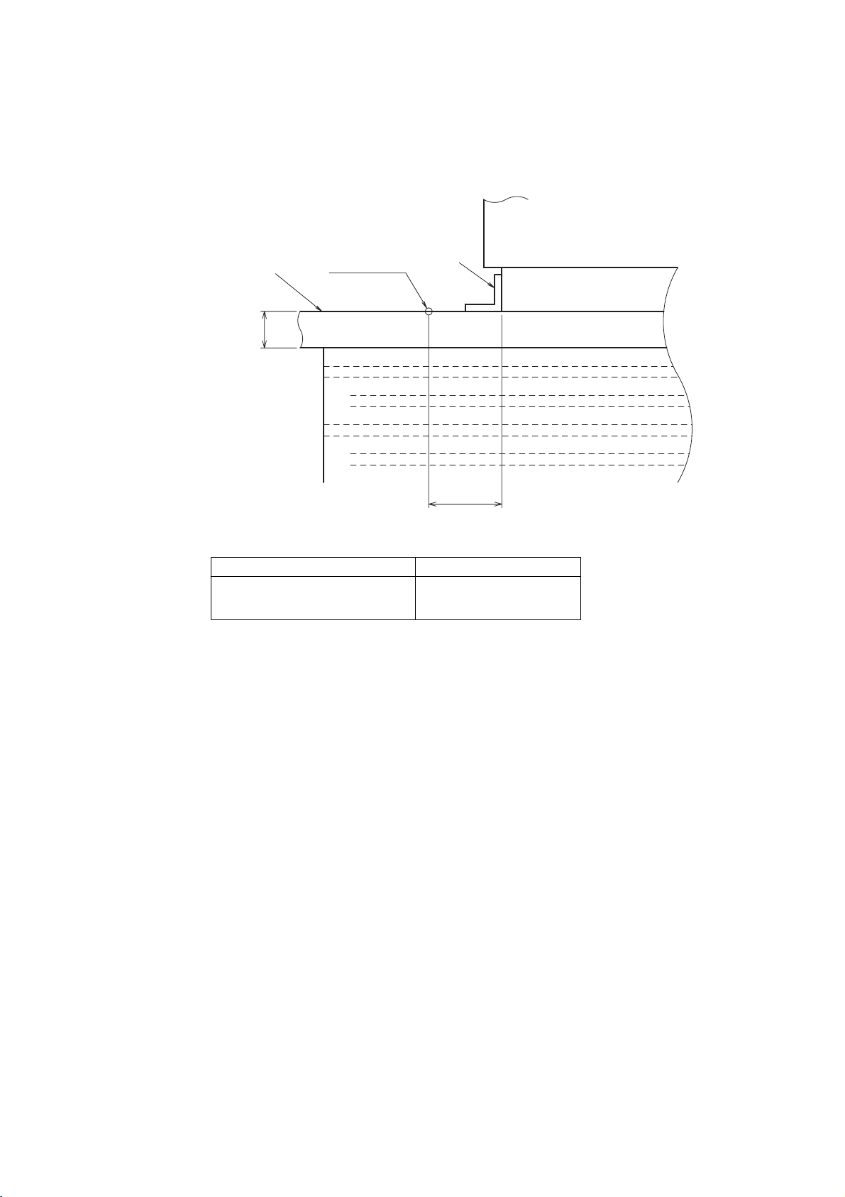
•PFAV-P300, 600VM-E-F
16
(2) Fresh air intake type
Remote controller
Inside section of control box
Indoor/Outdoor
transmission line
Power supply
3N~380/400/415V
50/60Hz
Remote controller board
Liquid crystal monitor
Terminal bed(Indoor unit)
LCD
TB6
R.B.
(accessory)
Note:7
TH24 Thermistor(Outdoor temp. detection)
2
3
1
3
1
3
CN33
T
52F
ZNR
F
XO6
1
1
1
CNT
CND
X4
2
1
2
11
M
CN28
3
2
1
CN20
CN21
3
2
1
X4
CN29
CN3T
CN60
CN31
R.B.
TB6
LCD
TB5
(Shield)
2
1
1
3
51F
52F
XO5
XO4
7
2
1
CN3A
M1
S
M2
3
5
CN90
CN2M
Indoor controller board
1
2
51F
CN7V
9
5
TH23TH22TH21
TB15
L2L1L3
TB2
1234567123456
123456
LEV1
M
3~
Fan motor
1
2
3
4
5
6
7
8
0
8
7
6
5
4
3
2
1
0
9
1
2
3
4
5
6
7
8
9
0
9
A
B
C
D
E
F
SW11
SW12
SW14 SW8 SW5 SWC
SWE
SW1 SW3 SW2 SW7 SW4
N
TH24
CN22
1
2
TH21
1
2
❈
P300
❈P
600
1234567
LEV1
654321
654321
CN7V CN60
M
LEV2
654321
M
Name
(2nd digit address set)
Electronic linear expan. valve 2LEV2
Symbol Name
Connector(Defrost output)
M
F
ZNR
T
LEV1
52F
51F
Symbol explanation
Symbol
Fan motor
Power source terminal bed
Transmission terminal bed
MA Remote controller terminal bed
Fuse<6.3A>
Varistor
Transformer
Electronic linear expan. valve 1
Contactor (Fan motor)
Over current relay(Fan motor)
Connector(Fan failure)
Switch (For trial run of fan)
Switch (For mode selection)
Switch
(For trial run)
Switch
(For four stages demand selection)
Switch
(For model selection)
Switch
(For mode selection)
Switch
(For capacity code)
Switch
(For mode selection)
Switch
(For model selection)
Switch
(Connection No. set)
Switch
(1st digit address set)
Thermistor(Piping temp. detection/gas)
SW7
SW1
SW14
SW12
SW11
SW2
SW3
SW4
Switch
X4 Auxiliary relay(Fan)
Thermistor(Piping temp. detection/liquid)
Thermistor(Supply air temp. detection)
SW5
SW8
SWC
SWE
TH23
TH22
TH21
CN33
CN28
TB15
TB5
TB2
t˚t˚t˚ t˚
t˚
Earth
U
Note: 1. (Heavy dotted line): Field wiring
2. Have all electric work done by a licensed electrician according
to the local regulations.
3. Earth leakage circuit breaker should be set up on the wiring of
the power supply.
4. Mark indicates terminal bed, connector.
5. Auto-restart function from power failure can be turned on by
setting SW1-9 dip switch to its ON position.
(Note: This function is not set to ON from the factory.)
6. Supply air thermistor is built in on the inside of the indoor unit.
A jumper is taped inside the control box without it being
connected to the connector.
Plug it into CN20 when using the supply air temperature to
control the room temperature.
Turn SW7-2 on the indoor unit to ON.
7. Indoor unit is supplied with a thermistor.
Install the sensor in the room to properly control the room
temperature.
Page 19
17
•PFAV-P900VM-E-F
LEV3
LEV2 LEV1
(Shield)
N
Indoor controller board No.2
TH21
TH21
31
123456
SW14
SW12
SW11
Indoor/Outdoor
transmission line
M1
S
M2
2
1
CN2M
CNP
1
3
CN20CN28
1212
X4
t˚ t˚ t˚
TH22 TH23 TH24
2121
CN29
21
CN21
CN22
CN3A
2
1
CN2M
CNP
1
3
SW8SW5
13 13
CN33
ZNR
F
X06
X05
X04
713 5
CND CN90
95
U
1
T
CN3T
31
CNT
2
t˚
345
U
6
M
7
CN7V
SWE
t˚
t˚ t˚
50/60Hz
380/400/415V
9
2
1
TH24
CN22
21
t˚
M
654321
SW4
X4
X2
52F
X1
F1
SW7 SW2
654321
CN60
X2
3
1
321
CN31
SW11
SW12
SW14
CN7V
6543217
SW3 SW1
SWC
51F
CN31
12
3
Indoor controller board No.1
CN90
CND
CNT
CN60
CN21
CN20
SW5
1
152
2
31 34156
L1
L2
TH22
SW2
SW7
13
CN3T
CN29
TH23
SWC
SW3
CN3A
1
2
SW4
Power supply
3N~
7
X04
X05
X06
F
ZNR
L3
52F
123456
T
CN33
31
CN28
3
1
1
2
M
M
313
121212
X1
3~
X4
51F
SW1
SW8
SWE
5
Remote controller
TB2
1
2
3
4
5
6
7
8
0
9
A
B
C
D
E
F
8
7
6
5
4
3
2
1
0
9
1
2
3
4
5
6
7
8
9
0
TB5
0
9
8
7
6
5
4
3
2
1
9
0
1
2
3
4
5
6
7
8
F
E
D
C
B
A
9
0
8
7
6
5
4
TB15
LCD
TB6
R.B.
3
2
1
Inside section of control box
X1,X2,X4
Fuse<6.3A>F1
F Fuse<6.3A>
Contactor (Fan motor)
Thermistor(Supply air temp. detection)TH21
Electronic linear expan. valve 3LEV3
Electronic linear expan. valve 2LEV2
Symbol Name
Fan motor
Electronic linear expan. valve 1
Remote controller board
Liquid crystal monitor
Power source terminal bed
Transmission terminal bed
Varistor
Transformer
Symbol explanation
MA Remote controller terminal bed
M
R.B.
LCD
TB2
TB5
TB15
ZNR
T
LEV1
Contactor (Fan motor)52F
51F Over current relay(Fan motor)
CN33 Connector(Defrost output)
Thermistor(Piping temp. detection/gas)
Thermistor(Piping temp. detection/liquid)
Thermistor(Outdoor temp. detection)
Switch (For model selection)SW7
SW1
SW14
SW12
SW11
SW4
SW5
SW8
Switch (For model selection)
Switch (Connection No. set)
Switch (For capacity code)
Switch (For four stages demand selection)
Switch (For mode selection)
Switch (2nd digit address set)
Switch (1st digit address set)
SW3
SW2
Switch (For mode selection)
TH22
TH24
TH23
TB6 Terminal bed(Indoor unit)
CN28 Connector(Fan failure)
SWE
SWC
Switch (For trial run)
Switch (For trial run of fan)
Switch (For mode selection)
Earth
(accessory)
Note:7
Note: 1. (Heavy dotted line): Field wiring
2. Have all electric work done by a licensed electrician according to the local regulations.
3. Earth leakage circuit breaker should be set up on the wiring of the power supply.
4. Mark indicates terminal bed, connector.
5. To enable the "auto recovery after power failure" function, set SW1-9 of both No. 1 and No. 2 circuit
boards to ON.
(Factory setting: OFF)
6. Supply air thermistor is built in on the inside of the indoor unit.
A jumper is taped inside the control box without it being connected to the connector.
Plug the jumper into CN20 on No. 1 circuit board when using the supply air temperature to control the
room temperature. Turn SW7-2 of both No. 1 and No. 2 circuit boards on the indoor unit to ON.
7. Indoor unit is supplied with a thermistor.
Install the sensor in the room to properly control the room temperature.
Page 20
18
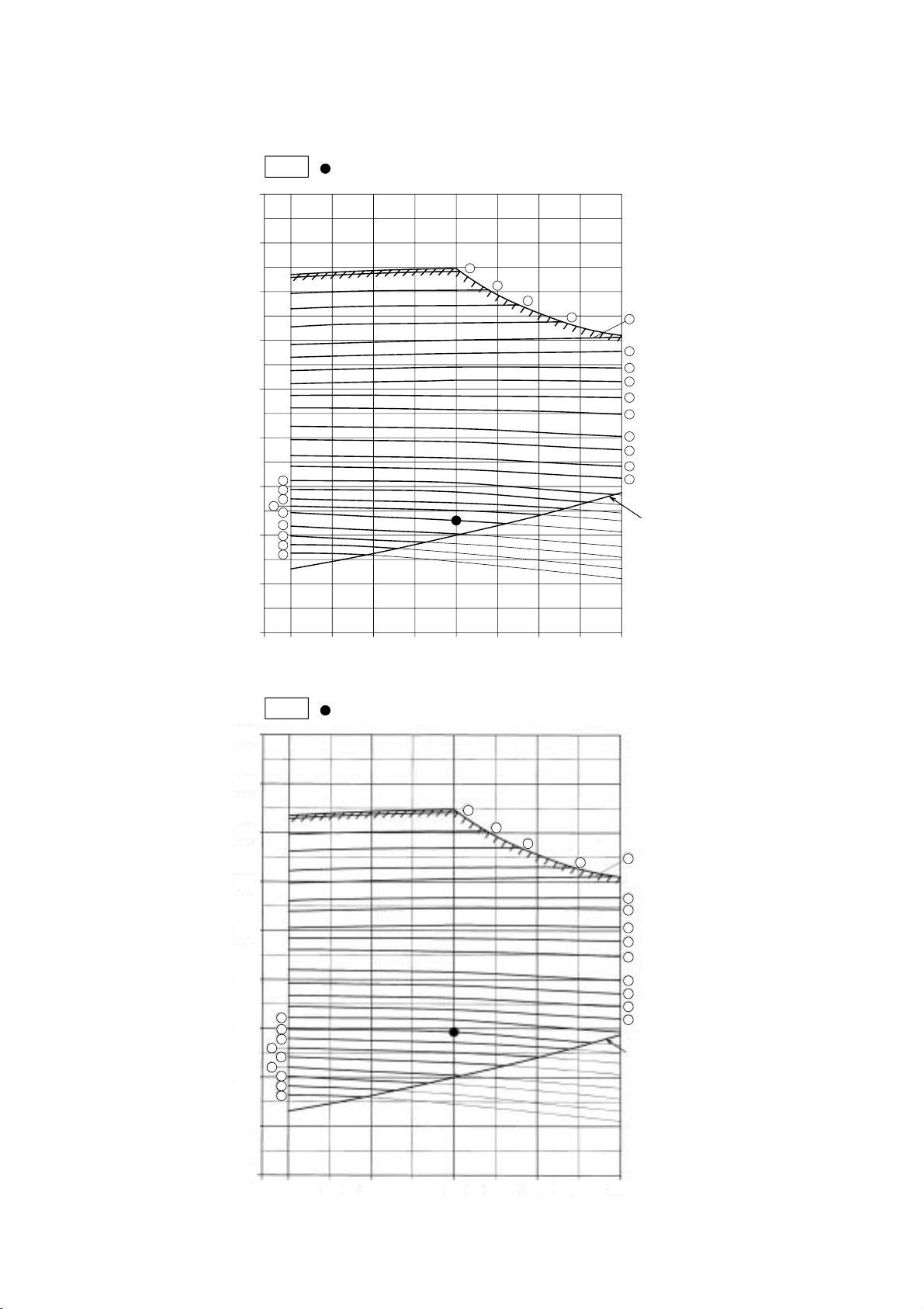
5. Sound Pressure Levels
•PFAV-P500VM-E
Power sorce : 3N 380/400/415V 50/60Hz
Note:The measuring point is the 1m from the bottom of the unit.
(1m from the front of the unit.)
32
8000Hz55dB(A)
38.5
4000Hz
44
2000Hz
47.5
1000Hz
51
500Hz
58.5
250Hz
63
125Hz
66
32 553645.546.550596368
63Hz
50Hz
60Hz
50Hz, 60Hz
NC Curve
·OCTAVE BAND CENTER FREQUENCIES (Hz)
·Approximate minimum
audible limit on
continuous noise.
90
80
70
60
50
40
30
20
10
63 125 250 500 1000 2000 4000 8000
NC-70
NC-60
NC-50
NC-30
NC-20
NC-40
OCTAVE BAND PRESSURE LEVEL (dB) 0 dB=20µPa
1m
1m
Measurement
location
Power sorce : 3N 380/400/415V 50/60Hz
Note:The measuring point is the 1m from the bottom of the unit.
(1m from the front of the unit.)
38
8000Hz62dB(A)
46.5
4000Hz
54
2000Hz
57
1000Hz
57.5
500Hz
60
250Hz
69
125Hz
77.5
33 5941.549535656.56573.5
63Hz
50Hz
60Hz
50Hz, 60Hz
NC Curve
·OCTAVE BAND CENTER FREQUENCIES (Hz)
·Approximate minimum
audible limit on
continuous noise.
90
80
70
60
50
40
30
20
10
63 125 250 500 1000 2000 4000 8000
NC-70
NC-60
NC-50
NC-30
NC-20
NC-40
OCTAVE BAND PRESSURE LEVEL (dB) 0 dB=20µPa
1m
1m
Measurement
location
•PFAV-P250VM-E
Page 21
19
•PFAV-P300VM-E-F
Power sorce : 3N 380/400/415V 50/60Hz
Note:The measuring point is the 1m from the bottom of the unit.
(1m from the front of the unit.)
44.5
8000Hz65dB(A)
49
4000Hz
56
2000Hz
60
1000Hz
62.5
500Hz
62.5
250Hz
63.5
125Hz
72.5
44.5 6549566062.562.563.572.5
63Hz
50Hz
60Hz
50Hz/60Hz
NC Curve
·OCTAVE BAND CENTER FREQUENCIES (Hz)
·Approximate minimum
audible limit on
continuous noise.
90
80
70
60
50
40
30
20
10
63 125 250 500 1000 2000 4000 8000
NC-70
NC-60
NC-50
NC-30
NC-20
NC-40
OCTAVE BAND PRESSURE LEVEL (dB) 0 dB=20µPa
1m
1m
Measurement
location
1m
1m
Power sorce : 3N 380/400/415V 50/60Hz
Measurement
location
Note:The measuring point is the 1m from the bottom of the unit.
(1m from the front of the unit.)
25.5
8000Hz
48.5
dB(A)
32
4000Hz
37.5
2000Hz
41
1000Hz
44.5
500Hz
52
250Hz
56.5
125Hz
59.5
25.5 48.529.5394043.552.556.561.5
63Hz
50Hz
60Hz
50Hz, 60Hz
NC Curve
·OCTAVE BAND CENTER FREQUENCIES (Hz)
·Approximate minimum
audible limit on
continuous noise.
90
80
70
60
50
40
30
20
10
63 125 250 500 1000 2000 4000 8000
NC-70
NC-60
NC-50
NC-30
NC-20
NC-40
OCTAVE BAND PRESSURE LEVEL (dB) 0 dB=20µPa
•PFAV-P750VM-E
Page 22
20
•PFAV-P900VM-E-F
Power sorce : 3N 380/400/415V 50/60Hz
Note:The measuring point is the 1m from the bottom of the unit.
(1m from the front of the unit.)
23
8000Hz53dB(A)
34.5
4000Hz
41
2000Hz
46.5
1000Hz
49
500Hz
54.5
250Hz
61.5
125Hz
69.5
17 5027.534.54145.55160.567
63Hz
50Hz
60Hz
50Hz, 60Hz
NC Curve
·OCTAVE BAND CENTER FREQUENCIES (Hz)
·Approximate minimum
audible limit on
continuous noise.
90
80
70
60
50
40
30
20
10
63 125 250 500 1000 2000 4000 8000
NC-70
NC-60
NC-50
NC-30
NC-20
NC-40
OCTAVE BAND PRESSURE LEVEL (dB) 0 dB=20µPa
1m
1m
Measurement
location
Power sorce : 3N 380/400/415V 50/60Hz
Note:The measuring point is the 1m from the bottom of the unit.
(1m from the front of the unit.)
32
8000Hz57dB(A)
41
4000Hz
43.5
2000Hz
51.5
1000Hz
52.5
500Hz
58
250Hz
67
125Hz
70
32 574143.551.552.5586770
63Hz
50Hz
60Hz
50Hz/60Hz
NC Curve
·OCTAVE BAND CENTER FREQUENCIES (Hz)
·Approximate minimum
audible limit on
continuous noise.
90
80
70
60
50
40
30
20
10
63 125 250 500 1000 2000 4000 8000
NC-70
NC-60
NC-50
NC-30
NC-20
NC-40
OCTAVE BAND PRESSURE LEVEL (dB) 0 dB=20µPa
1m
1m
Measurement
location
•PFAV-P600VM-E-F
Page 23
21
6. Vibration levels
•PFAV indoor unit
Concrete
Measurement
location
Leg
PFAV Unit
10cm
20cm
Vibration Levels [dBA]
40 or less
Model
PFAV-P250,500,750VM-E
PFAV-P300,600,900VM-E-F
Page 24
22
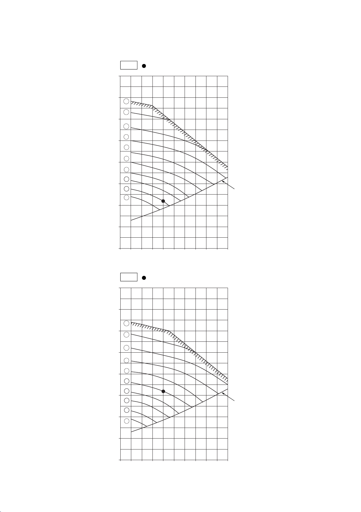
7. Fan characteristic curves
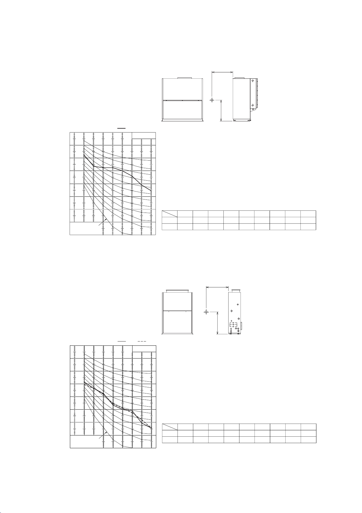
11070 75 80 85 90 95 100 105
100
200
300
400
500
700
900
800
600
2.2kW
0
14
13
12
11
5
6
7
8
9
10
4
1
2
3
15
20
21
22
23
16
17
18
19
······Standard
50Hz
Internal resistance
Airflow rate < m
3
/ min >
Total static pressure < Pa >
······Standard
60Hz
11070 75 80 85 90 95 100 105
100
200
300
400
500
700
900
800
600
0
23
22
21
20
19
18
17
16
2.2kW
14
13
12
11
10
9
8
7
6
5
4
3
2
1
15
Internal resistance
Total static pressure < Pa >
Airflow rate < m
3
/ min >
•PFAV-P250VM-E
Page 25
23
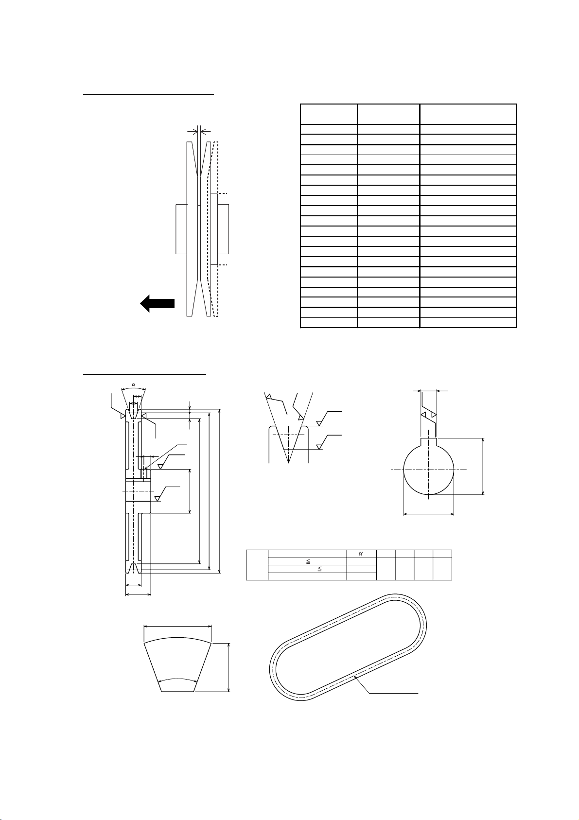
Specification(Pulley , Belt )
Standard(Factory set) <50Hz>
Motor
Motor pulley Fan pulley
V-belt (H)
<mm / in>
Over current relay
(Fan motor)
Pitch diameter
(Changeability) <PCø>
2.2kW
Bore (E) <ø>Bore (E) <ø>
Nominal
diameter (B) <ø>
140.2 28 212 20 1423 / 56 5.0A
Standard <60Hz>
Motor
Motor pulley Fan pulley
V-belt (H)
<mm / in>
Over current relay
(Fan motor)
Pitch diameter
(Changeability) <PCø>
2.2kW
Bore (E) <ø>Bore <ø>
Nominal
diameter (B) <ø>
129.1
(factory set 140.2)
28 212 20 1423 / 56 5.0A
1
2
3
4
5
6
7
8
9
10
11
12
13
14
15
16
17
18
19
20
21
22
23
1663
1620
1581
1540
1499
1459
1418
1378
1344
1308
1261
1225
1179
1139
1100
1060
1018
992
955
908
868
820
785
159
159
159
159
159
159
159
159
159
159
159
159
159
159
159
159
159
159
159
159
159
159
159
3
1/2
1·1/4
2
2·3/4
2·1/2
4·1/4
1·1/2
2·1/2
3
4
4·3/4
3/4
1·3/4
2·3/4
3·3/4
1/4
1
2
2
3·1/4
4·3/4
3
28
28
28
28
28
28
28
28
28
28
28
28
28
28
28
28
28
28
28
28
28
28
28
31.3
31.3
31.3
31.3
31.3
31.3
31.3
31.3
31.3
31.3
31.3
31.3
31.3
31.3
31.3
31.3
31.3
31.3
31.3
31.3
31.3
31.3
31.3
8
8
8
8
8
8
8
8
8
8
8
8
8
8
8
8
8
8
8
8
8
8
8
118
132
132
132
132
132
132
150
150
150
150
150
180
180
180
180
212
212
212
224
224
224
250
127
141
141
141
141
141
141
159
159
159
159
159
189
189
189
189
221
221
221
233
233
233
259
102
116
116
116
116
116
116
134
134
134
134
134
164
164
164
164
196
196
196
208
208
208
234
50
50
50
50
50
50
50
56
56
56
56
56
56
56
56
56
54
54
54
54
54
54
54
20
20
20
20
20
20
20
20
20
20
20
20
20
20
20
20
20
20
20
20
20
20
20
23.5
23.5
23.5
23.5
23.5
23.5
23.5
23.5
23.5
23.5
23.5
23.5
23.5
23.5
23.5
23.5
23.5
23.5
23.5
23.5
23.5
23.5
23.5
7
7
7
7
7
7
7
7
7
7
7
7
7
7
7
7
7
7
7
7
7
7
7
1270 / 50
1296 / 51
1296 / 51
1296 / 51
1296 / 51
1296 / 51
1296 / 51
1321 / 52
1321 / 52
1321 / 52
1321 / 52
1321 / 52
1372 / 54
1372 / 54
1372 / 54
1372 / 54
1423 / 56
1423 / 56
1423 / 56
1423 / 56
1423 / 56
1423 / 56
1474 / 58
17.7
16.5
16.8
17.2
17.6
18.0
18.4
16.9
17.4
17.7
18.2
19.0
16.8
17.3
17.8
18.4
16.6
17.5
18.0
18.0
18.6
19.6
18.8
7.0
6.9
6.9
6.9
7.0
7.0
7.1
6.9
7.0
7.0
7.0
7.1
6.9
6.9
7.0
7.0
6.8
6.9
6.9
6.7
6.8
6.9
6.8
Rotational
speed
<rpm>
No.
Outside
diameter
<ø>
Outside
diameter (A)
<ø>
Nominal
Diameter (B)
<ø>
Deflection
force
<N>
Amount
of
deflection
<mm>
14.7
15.1
15.3
15.6
15.8
14.9
14.7
15.0
15.3
15.6
16.0
14.5
15.3
15.7
16.1
16.5
16.3
16.6
15.9
16.6
15.7
16.9
17.5
6.9
7.0
7.0
7.0
7.1
6.9
6.9
6.9
7.0
7.0
7.1
6.8
6.9
6.9
7.0
7.0
6.8
6.9
6.8
6.9
6.5
6.6
6.7
Slide peace
Rotation
number
Bore (E)
<ø>
Bore (E)
<ø>
(C)
<ø>
(D)
<ø>
(F)
<mm>
(G)
<mm>
(F)
<mm>
(G)
<mm>
V-belt (H)
<mm / in>
Motor 2.2kW,1450rpm <50Hz>
Motor pulley Fan pulley
1
2
3
4
5
6
7
8
9
10
11
12
13
14
15
16
17
18
19
20
21
22
23
1664
1622
1579
1535
1506
1458
1422
1375
1339
1304
1248
1221
1181
1141
1101
1060
1022
994
967
908
879
825
787
159
159
159
159
159
159
159
159
159
159
159
159
159
159
159
159
159
159
159
159
159
159
159
1·1/2
2·1/2
3
3·3/4
4·1/4
1·1/2
3/4
1·3/4
2·1/2
3·1/4
4·1/4
1/4
1·1/4
2·1/4
3·1/4
4·1/4
3·3/4
4·1/2
2·1/4
4
1·3/4
3·1/2
4·3/4
28
28
28
28
28
28
28
28
28
28
28
28
28
28
28
28
28
28
28
28
28
28
28
31.3
31.3
31.3
31.3
31.3
31.3
31.3
31.3
31.3
31.3
31.3
31.3
31.3
31.3
31.3
31.3
31.3
31.3
31.3
31.3
31.3
31.3
31.3
8
8
8
8
8
8
8
8
8
8
8
8
8
8
8
8
8
8
8
8
8
8
8
150
150
150
150
150
180
180
180
180
180
180
212
212
212
212
212
224
224
250
250
280
280
280
159
159
159
159
159
189
189
189
189
189
189
221
221
221
221
221
233
233
259
259
289
289
289
134
134
134
134
134
164
164
164
164
164
164
196
196
196
196
196
208
208
234
234
264
264
264
56
56
56
56
56
56
56
56
56
56
56
54
54
54
54
54
54
54
54
54
54
54
54
20
20
20
20
20
20
20
20
20
20
20
20
20
20
20
20
20
20
20
20
20
20
20
23.5
23.5
23.5
23.5
23.5
23.5
23.5
23.5
23.5
23.5
23.5
23.5
23.5
23.5
23.5
23.5
23.5
23.5
23.5
23.5
23.5
23.5
23.5
7
7
7
7
7
7
7
7
7
7
7
7
7
7
7
7
7
7
7
7
7
7
7
1321 / 52
1321 / 52
1321 / 52
1321 / 52
1321 / 52
1372 / 54
1372 / 54
1372 / 54
1372 / 54
1372 / 54
1372 / 54
1423 / 56
1423 / 56
1423 / 56
1423 / 56
1423 / 56
1423 / 56
1423 / 56
1474 / 58
1474 / 58
1499 / 59
1499 / 59
1499 / 59
Rotational
speed
<rpm>
No.
Outside
diameter
<ø>
Outside
diameter (A)
<ø>
Nominal
Diameter (B)
<ø>
Slide peace
Rotation
number
Bore (E)
<ø>
Bore (E)
<ø>
(C)
<ø>
(D)
<ø>
(F)
<mm>
(G)
<mm>
(F)
<mm>
(G)
<mm>
V-belt (H)
<mm / in>
Motor 2.2kW,1750rpm <60Hz>
Motor pulley Fan pulley
Deflection
force
<N>
Amount
of
deflection
<mm>
Page 26
24
Variable-width pulley PC ø table
Shape of the pulley (unit:mm)
Fixed disc
must be
* See p.40 for "How to choose the pulley."
placed on
the motor
side.
Number of
turns to apply
Pulley distance
(mm)
PC ø of variable-width
pulleys for 2.2kW motor
0
1/4
1/2
3/4
1
1·1/4
1·1/2
1·3/4
2
2·1/4
2·1/2
2·3/4
3
3·1/4
3·1/2
3·3/4
4
4·1/4
4·1/2
4·3/4
(0)
(0.4)
(0.8)
(1.1)
(1.5)
(1.9)
(2.3)
(2.6)
(3.0)
(3.4)
(3.8)
(4.1)
(4.5)
(4.9)
(5.3)
(5.6)
(6.0)
(6.4)
(6.8)
(7.1)
150.0
148.8
147.5
146.3
145.1
143.9
142.6
141.4
140.2
139.0
137.7
136.5
135.3
134.1
132.8
131.6
130.4
129.1
127.9
126.7
Pulley
M8
(keyway)
e
12.5
k
5.5
o
9.5
ko
12.5
m
Rz 3.2
Rz 3.2
Rz 12.5
B (d
m
: Pulley nominal diameter)
Belt
dm:Pulley nominal diameter
201 < d
m
dm 126
34˚
36˚
38˚
Rz 6.3
Rz 6.3
Rz 3.2
Rz 3.2
C
A (d : Pulley outside diameter)
25
40
11
e
kk
m
Rz 6.3
Rz 6.3
Rz 3.2
D
E
G
F
161 < dm 200
40˚
12.5
9
H (outer center)
Page 27
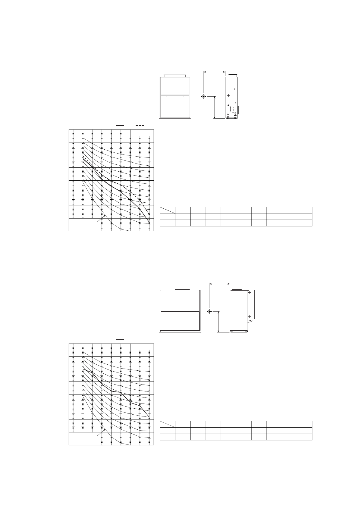
25
•PFAV-P500VM-E
180160140 220 240200
200
0
400
500
300
100
150 170 190 210 230
600
700
800
2
3
1
4
5
6
7
8
9
10
5.5KW
······Standard
50Hz
Internal resistance
Airflow rate < m
3
/ min >
Total static pressure < Pa >
······Standard
60Hz
Internal resistance
Airflow rate < m
3
/ min >
Total static pressure < Pa >
700
600
500
400
300
200
100
240230220210200190180170160150
0
140
800
3
2
1
5
6
7
8
9
10
4
5.5KW
Page 28
26
Specification(Pulley , Belt )
Standard(Factory set) <50Hz>
Motor
Motor pulley Fan pulley
V-belt (H)
<mm / in>
Over current relay
(Fan motor)
Nominal
diameter (B) <ø>
5.5kW
Bore (E) <ø>Bore (E) <ø>
Nominal
diameter (B) <ø>
118 38 236 32 1042 / 41 11A
Standard <60Hz>
Motor
Motor pulley Fan pulley
V-belt (H)
<mm / in>
Over current relay
(Fan motor)
Nominal
diameter (B) <ø>
5.5kW
Bore (E) <ø>Bore (E) <ø>
Nominal
diameter (B) <ø>
118
Note1. Use two V-belts for P500 indoor unit.
Note1. Use two V-belts for P500 indoor unit.
38 236 32 1042 / 41 11A
1
2
3
4
5
6
7
8
9
10
1135
1094
1034
979
929
884
835
796
753
712
190
170
170
180
190
200
212
236
236
250
201
181
181
191
201
211
223
247
247
261
171
151
151
161
171
181
193
217
217
231
80
71
71
71
80
80
80
80
80
80
32
32
32
32
32
32
32
32
32
32
36
36
36
36
36
36
36
36
36
36
10
10
10
10
10
10
10
10
10
10
966 / 38
889 / 35
889 / 35
915 / 36
915 / 36
940 / 37
966 / 38
1016 / 40
1042 / 41
1042 / 41
Rotational
speed
<rpm>
No.
Outside
diameter (A)
<ø>
Nominal
Diameter (B)
<ø>
Bore (E)
<ø>
(C)
<ø>
(D)
<ø>
(F)
<mm>
(G)
<mm>
145
125
118
118
118
118
118
125
118
118
156
136
129
129
129
129
129
136
129
129
126
106
99
99
99
99
99
106
99
99
71
70
70
70
70
70
70
70
70
70
38
38
38
38
38
38
38
38
38
38
41.3
42
42
42
42
42
42
42
42
42
10
10
10
10
10
10
10
10
10
10
Outside
diameter (A)
<ø>
Nominal
Diameter (B)
<ø>
Bore (E)
<ø>
(C)
<ø>
(D)
<ø>
(F)
<mm>
(G)
<mm>
V-belt (H)
<mm / in>
Motor 5.5kW,1450rpm <50Hz>
Motor pulley Fan pulley
1
2
3
4
5
6
7
8
9
10
1105
1059
1005
946
894
847
798
753
701
660
224
190
200
212
224
236
250
280
300
300
235
201
211
223
235
247
261
291
311
311
205
171
181
193
205
217
231
261
281
281
80
80
80
80
80
80
80
80
80
80
32
32
32
32
32
32
32
32
32
32
36
36
36
36
36
36
36
36
36
36
10
10
10
10
10
10
10
10
10
10
1016 / 40
915 / 36
940 / 37
966 / 38
991 / 39
1042 / 41
1042 / 41
1118 / 44
1143 / 45
1143 / 45
Rotational
speed
<rpm>
No.
Outside
diameter (A)
<ø>
Nominal
Diameter (B)
<ø>
Bore (E)
<ø>
(C)
<ø>
(D)
<ø>
(F)
<mm>
(G)
<mm>
145
118
118
118
118
118
118
125
125
118
156
129
129
129
129
129
129
136
136
129
126
99
99
99
99
99
99
106
106
99
71
70
70
70
70
70
70
70
70
70
38
38
38
38
38
38
38
38
38
38
41.3
42
42
42
42
42
42
42
42
42
10
10
10
10
10
10
10
10
10
10
Outside
diameter (A)
<ø>
Nominal
Diameter (B)
<ø>
Bore (E)
<ø>
(C)
<ø>
(D)
<ø>
(F)
<mm>
(G)
<mm>
V-belt (H)
<mm / in>
Motor 5.5kW,1750rpm <60Hz>
Motor pulley Fan pulley
23.2
25.9
27.2
27.6
27.6
28.5
28.5
27.6
28.9
29.9
3.5
3.4
3.4
3.5
3.3
3.4
3.4
3.4
3.6
3.4
21.4
23.8
24.5
24.5
24.9
24.9
25.7
25.4
26.2
27.3
3.4
3.3
3.4
3.4
3.4
3.6
3.4
3.4
3.2
3.3
Deflection
force
<N>
Amount
of
deflection
<mm>
Deflection
force
<N>
Amount
of
deflection
<mm>
Page 29
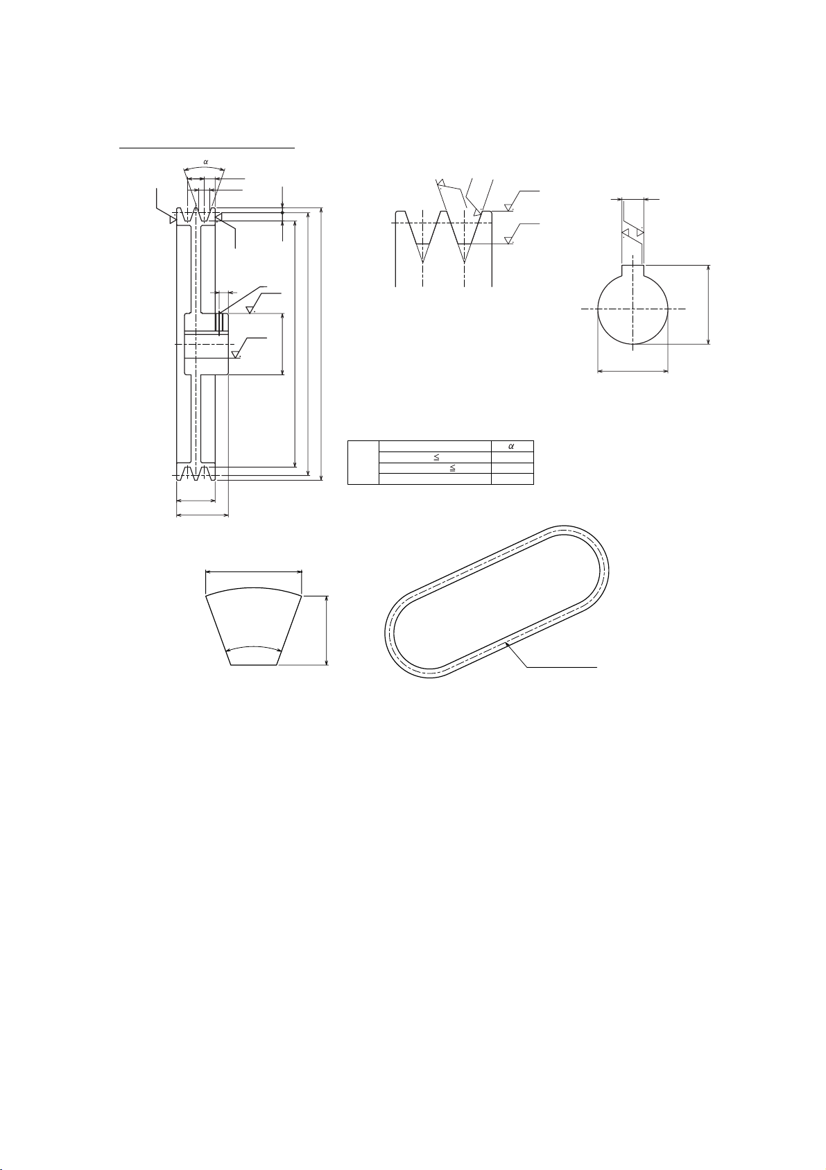
27
Shape of the pulley (unit:mm)
* See p.40 for "How to choose the pulley."
40˚
16.5
11.0
H (outer center)
M8
Rz 6.3
Rz 3.2
Rz 6.3
Rz 6.3
19
Rz 3.2
Rz 3.2
(keyway)
9.5 5.5
12.5
59
44
12.5
C
Rz 3.2
R
z 3
.2
Rz 6.3
Rz 6.3
D
A (d:Pulley outside diameter)
B (dm:Pulley nominal diameter)
11
Belt
dm:Pulley nominal diameter
201 < d
m
dm 160
34˚
36˚
38˚
161 < d
m
200
E
G
F
Page 30
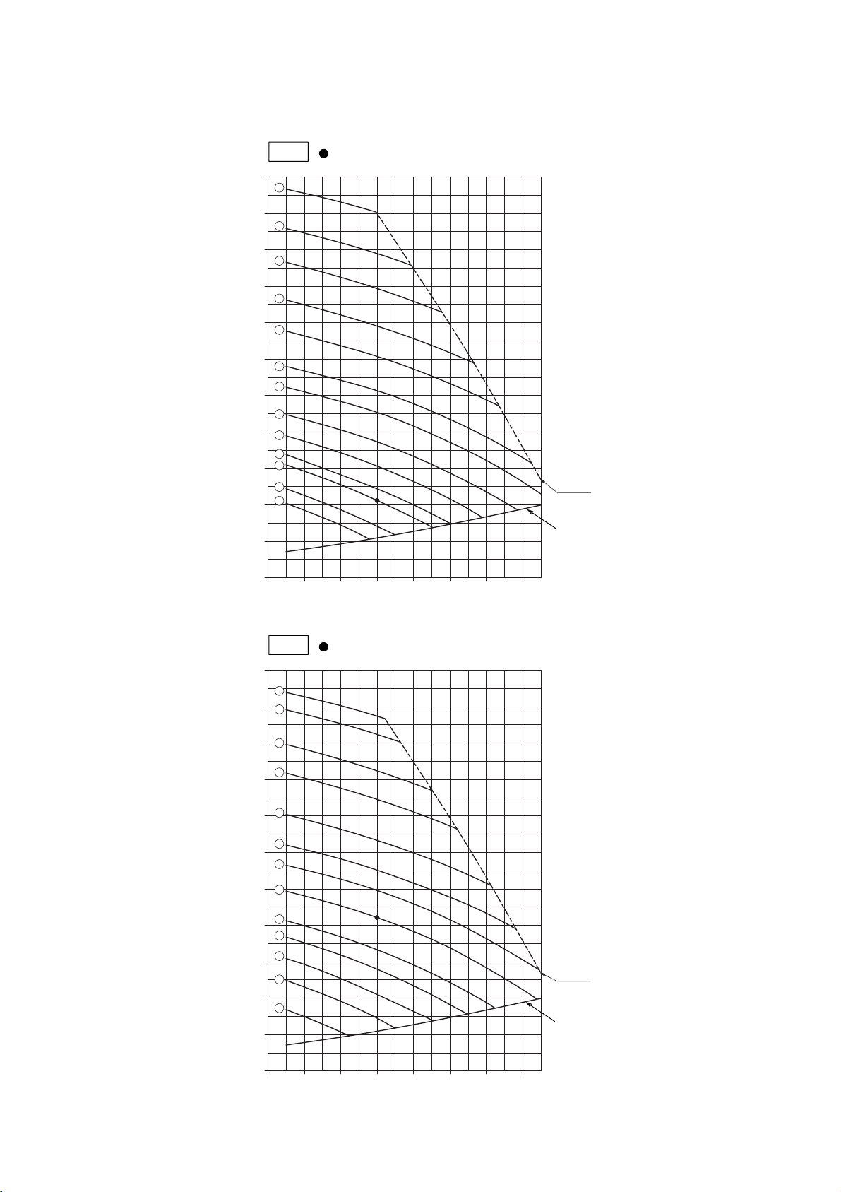
28
7.5kW
1
3
4
5
6
9
11
2
7
8
13
12
10
340320300280260240220
0
1100
1000
900
800
700
600
500
400
300
200
100
······Standard
50Hz
Internal resistance
Airflow rate < m
3
/ min >
Total static pressure < Pa >
······Standard
60Hz
Internal resistance
Airflow rate < m
3
/ min >
Total static pressure < Pa >
7.5kW
1
2
3
4
5
6
7
8
9
10
11
13
12
100
200
300
400
500
600
700
800
900
1000
1100
0
220 240 260 280 300 320 340
•PFAV-P750VM-E
Page 31

29
Specification(Pulley , Belt )
Standard(Factory set) <50Hz>
Motor
Motor pulley Fan pulley
V-belt (H)
<mm / in>
Over current relay
(Fan motor)
Nominal
diameter (B) <ø>
7.5kW
Bore (E) <ø>Bore (E) <ø>
Nominal
diameter (B) <ø>
145 38 300 32 1347 / 53 15A
Standard <60Hz>
Motor
Motor pulley Fan pulley
V-belt (H)
<mm / in>
Over current relay
(Fan motor)
Nominal
diameter (B) <ø>
7.5kW
Bore (E) <ø>Bore (E) <ø>
Nominal
diameter (B) <ø>
145 38 300 32 1347 / 53 15A
1
2
3
4
5
6
7
8
9
10
11
12
13
1193
1134
1083
1025
976
918
875
822
773
725
701
653
621
243
243
300
300
315
300
315
300
300
300
300
300
315
254
254
311
311
326
311
326
311
311
311
311
311
326
224
224
281
281
296
281
296
281
281
281
281
281
296
70
70
90
90
90
90
90
90
90
90
90
90
90
32
32
32
32
32
32
32
32
32
32
32
32
32
36
36
36
36
36
36
36
36
36
36
36
36
36
10
10
10
10
10
10
10
10
10
10
10
10
10
1321 / 52
1321 / 52
1448 / 57
1448 / 57
1448 / 57
1423 / 56
1423 / 56
1372 / 54
1372 / 54
1347 / 53
1347 / 53
1347 / 53
1347 / 53
Rotational
speed
<rpm>
No.
Outside
diameter (A)
<ø>
Nominal
Diameter (B)
<ø>
Bore (E)
<ø>
(C)
<ø>
(D)
<ø>
(F)
<mm>
(G)
<mm>
200
190
224
212
212
190
190
170
160
150
145
135
135
211
201
235
223
223
201
201
181
171
161
156
146
146
181
171
205
193
193
171
171
151
141
131
126
116
116
80
71
80
80
80
71
71
71
71
71
71
63
63
38
38
38
38
38
38
38
38
38
38
38
38
38
41.3
41.3
41.3
41.3
41.3
41.3
41.3
41.3
41.3
41.3
41.3
41.3
41.3
10
10
10
10
10
10
10
10
10
10
10
10
10
Outside
diameter (A)
<ø>
Nominal
Diameter (B)
<ø>
Bore (E)
<ø>
(C)
<ø>
(D)
<ø>
(F)
<mm>
(G)
<mm>
V-belt (H)
<mm / in>
Motor 7.5kW,1450rpm <50Hz>
Motor pulley Fan pulley
1
2
3
4
5
6
7
8
9
10
11
12
13
1178
1152
1100
1056
992
944
(900)
846
788
750
700
656
591
315
243
300
315
300
315
300
300
300
315
400
400
400
326
254
311
326
311
326
311
311
311
326
411
411
411
296
224
281
296
281
296
281
281
281
296
381
381
381
90
70
90
90
90
90
90
90
90
90
90
90
90
32
32
32
32
32
32
32
32
32
32
32
32
32
36
36
36
36
36
36
36
36
36
36
36
36
36
10
10
10
10
10
10
10
10
10
10
10
10
10
1474 / 58
1270 / 50
1423 / 56
1423 / 56
1372 / 54
1372 / 54
1372 / 54
1347 / 53
1347 / 53
1347 / 53
1550 / 61
1550 / 61
1550 / 61
Rotational
speed
<rpm>
No.
Outside
diameter (A)
<ø>
Nominal
Diameter (B)
<ø>
Bore (E)
<ø>
(C)
<ø>
(D)
<ø>
(F)
<mm>
(G)
<mm>
212
160
190
190
170
170
170
145
135
135
160
150
135
235
171
201
201
181
181
181
156
146
146
171
161
146
193
141
171
171
151
151
151
126
116
116
141
131
116
80
71
71
71
71
71
71
71
71
71
71
71
71
38
38
38
38
38
38
38
38
38
38
38
38
38
41.3
41.3
41.3
41.3
41.3
41.3
41.3
41.3
41.3
41.3
41.3
41.3
41.3
10
10
10
10
10
10
10
10
10
10
10
10
10
Outside
diameter (A)
<ø>
Nominal
Diameter (B)
<ø>
Bore (E)
<ø>
(C)
<ø>
(D)
<ø>
(F)
<mm>
(G)
<mm>
V-belt (H)
<mm / in>
Motor 7.5kW,1450rpm <50Hz>
Motor pulley
Fan pulley
Note1. Use two V-belts for P750 indoor unit.
Note1. Use two V-belts for P750 indoor unit.
Note2. Set the scroll damper opening to 2 for the pulley set 7 . (Factory setting : 0)
23.9
25.3
23.3
24.2
24.2
25.6
26.4
28.4
29.6
31.6
32.4
34.4
35.5
5.0
5.1
4.9
5.1
4.8
5.1
4.8
4.9
4.9
4.8
4.9
5.0
4.7
22.6
25.4
23.3
24.0
25.2
25.6
25.2
28.2
29.7
30.6
28.9
30.2
32.5
5.0
5.0
5.1
4.8
4.9
4.6
4.9
4.9
5.0
4.7
4.6
4.7
4.8
Deflection
force
<N>
Amount
of
deflection
<mm>
Deflection
force
<N>
Amount
of
deflection
<mm>
Page 32

30
Shape of the pulley (unit:mm)
* See p.40 for "How to choose the pulley."
40˚
16.5
11.0
H (outer center)
M8
Rz 6.3
Rz 3.2
Rz 6.3
Rz 6.3
19
Rz 3.2
Rz 3.2
(keyway)
9.5 5.5
12.5
59
44
12.5
C
Rz 3.2
R
z 3
.2
Rz 6.3
Rz 6.3
D
A (d:Pulley outside diameter)
B (dm:Pulley nominal diameter)
11
Belt
dm:Pulley nominal diameter
201 < d
m
dm 160
34˚
36˚
38˚
161 < d
m
200
E
G
F
Page 33

31
•PFAV-P300VM-E-F
36 54
1.5kW
4540 50
600
800
700
500
400
300
200
100
0
22
20
19
18
17
16
15
14
13
12
11
10
9
7
8
5
2
4
3
1
23
21
6
24
25
······Standard
50Hz
Internal resistance
Airflow rate < m
3
/ min >
Total static pressure < Pa >
Internal resistance
Airflow rate < m
3
/ min >
Total static pressure < Pa >
······Standard
60Hz
36 54
1.5kW
4540 50
600
800
700
500
400
300
200
100
0
22
20
23
21
19
18
14
17
16
15
13
12
11
10
9
8
7
6
5
4
2
3
1
Page 34

32
Specification(Pulley , Belt )
Standard(Factory set) <50Hz>
Motor
Motor pulley Fan pulley
V-belt (H)
<mm / in>
Over current relay
(Fan motor)
Pitch diameter
(Changeability) <PCø>
1.5kW
Bore (E) <ø>Bore <ø>
Nominal
diameter (B) <ø>
140 24 280 20 1499 / 59 3.6A
Motor
Motor pulley Fan pulley
V-belt (H)
<mm / in>
Over current relay
(Fan motor)
Pitch diameter
(Changeability) <PCø>
1.5kW
Bore (E) <ø>Bore <ø>
Nominal
diameter (B) <ø>
116.7
(factory set 140)
24 280 20 1499 / 59 3.6A
Standard <60Hz>
1
2
3
4
5
6
7
8
9
10
11
12
13
14
15
16
17
18
19
20
21
22
23
24
25
1600
1538
1497
1457
1417
1376
1336
1306
1259
1223
1175
1140
1098
1059
1019
980
940
906
858
819
787
755
725
700
661
149
149
149
149
149
149
149
149
149
149
149
149
149
149
149
149
149
149
149
149
149
149
149
149
149
2
0
3/4
1·1/2
2·1/4
3
3·3/4
1
2
2·3/4
3·3/4
4·1/2
3/4
1·3/4
2·3/4
3·3/4
4·3/4
0
1·1/2
2·3/4
3·3/4
2·1/4
0
1
2·1/2
24
24
24
24
24
24
24
24
24
24
24
24
24
24
24
24
24
24
24
24
24
24
24
24
24
27.3
27.3
27.3
27.3
27.3
27.3
27.3
27.3
27.3
27.3
27.3
27.3
27.3
27.3
27.3
27.3
27.3
27.3
27.3
27.3
27.3
27.3
27.3
27.3
27.3
8
8
8
8
8
8
8
8
8
8
8
8
8
8
8
8
8
8
8
8
8
8
8
8
8
118
132
132
132
132
132
132
150
150
150
150
150
180
180
180
180
180
224
224
224
224
224
280
280
280
127
141
141
141
141
141
141
159
159
159
159
159
189
189
189
189
189
233
233
233
233
233
289
289
289
102
116
116
116
116
116
116
134
134
134
134
134
164
164
164
164
164
196
196
196
196
196
234
234
234
50
50
50
50
50
50
50
56
56
56
56
56
56
56
56
56
56
54
54
54
54
54
54
54
54
20
20
20
20
20
20
20
20
20
20
20
20
20
20
20
20
20
20
20
20
20
20
20
20
20
23.5
23.5
23.5
23.5
23.5
23.5
23.5
23.5
23.5
23.5
23.5
23.5
23.5
23.5
23.5
23.5
23.5
23.5
23.5
23.5
23.5
23.5
23.5
23.5
23.5
7
7
7
7
7
7
7
7
7
7
7
7
7
7
7
7
7
7
7
7
7
7
7
7
7
1245 / 49
1270 / 50
1270 / 50
1270 / 50
1245 / 49
1245 / 49
1245 / 49
1296 / 51
1296 / 51
1296 / 51
1296 / 51
1296 / 51
1347 / 53
1347 / 53
1347 / 53
1347 / 53
1347 / 53
1423 / 56
1423 / 56
1423 / 56
1423 / 56
1423 / 56
1499 / 59
1499 / 59
1499 / 59
Rotational
speed
<rpm>
No.
Outside
diameter
<ø>
Outside
diameter (A)
<ø>
Nominal
Diameter (B)
<ø>
Slide peace
Rotation
number
Bore (E)
<ø>
Bore (E)
<ø>
(C)
<ø>
(D)
<ø>
(F)
<mm>
(G)
<mm>
(F)
<mm>
(G)
<mm>
V-belt (H)
<mm / in>
Motor 1.5kW,1450rpm <50Hz>
Motor pulley Fan pulley
1
2
3
4
5
6
7
8
9
10
11
12
13
14
15
16
17
18
19
20
21
22
23
1596
1547
1505
1462
1419
1376
1337
1302
1254
1218
1182
1135
1094
1055
1017
979
941
912
877
825
783
753
729
149
149
149
149
149
149
149
149
149
149
149
149
149
149
149
149
149
149
149
149
149
149
149
4
1·1/2
2·1/4
3
3·3/4
4·1/2
1/2
1·1/4
2·1/4
3
3·3/4
4·3/4
0
1
2
3
4
4·3/4
3
4·1/2
3
2·1/4
4·3/4
24
24
24
24
24
24
24
24
24
24
24
24
24
24
24
24
24
24
24
24
24
24
24
27.3
27.3
27.3
27.3
27.3
27.3
27.3
27.3
27.3
27.3
27.3
27.3
27.3
27.3
27.3
27.3
27.3
27.3
27.3
27.3
27.3
27.3
27.3
8
8
8
8
8
8
8
8
8
8
8
8
8
8
8
8
8
8
8
8
8
8
8
132
150
150
150
150
150
180
180
180
180
180
180
224
224
224
224
224
224
250
250
280
280
280
141
159
159
159
159
159
189
189
189
189
189
189
233
233
233
233
233
233
259
259
289
289
289
116
134
134
134
134
134
164
164
164
164
164
164
208
208
208
208
208
208
234
234
264
264
264
50
56
56
56
56
56
56
56
56
56
56
56
54
54
54
54
54
54
54
54
54
54
54
20
20
20
20
20
20
20
20
20
20
20
20
20
20
20
20
20
20
20
20
20
20
20
23.5
23.5
23.5
23.5
23.5
23.5
23.5
23.5
23.5
23.5
23.5
23.5
23.5
23.5
23.5
23.5
23.5
23.5
23.5
23.5
23.5
23.5
23.5
7
7
7
7
7
7
7
7
7
7
7
7
7
7
7
7
7
7
7
7
7
7
7
1245 / 49
1296 / 51
1296 / 51
1296 / 51
1296 / 51
1296 / 51
1347 / 53
1347 / 53
1347 / 53
1347 / 53
1347 / 53
1347 / 53
1423 / 56
1423 / 56
1423 / 56
1423 / 56
1423 / 56
1423 / 56
1474 / 58
1474 / 58
1499 / 59
1499 / 59
1499 / 59
Rotational
speed
<rpm>
No.
Outside
diameter
<ø>
Outside
diameter (A)
<ø>
Nominal
Diameter (B)
<ø>
Slide peace
Rotation
number
Bore (E)
<ø>
Bore (E)
<ø>
(C)
<ø>
(D)
<ø>
(F)
<mm>
(G)
<mm>
(F)
<mm>
(G)
<mm>
V-belt (H)
<mm / in>
Motor 1.5kW,1750rpm <60Hz>
Motor pulley Fan pulley
12.8
12.1
12.4
12.6
12.9
13.2
13.5
12.5
12.8
13.3
13.7
14.1
12.6
12.9
13.3
13.7
14.2
12.7
13.2
13.7
14.2
13.5
12.8
13.2
14.2
6.8
6.7
6.8
6.8
6.7
6.7
6.8
6.8
6.8
6.9
6.9
7.0
6.8
6.8
6.9
7.0
7.0
6.7
6.8
6.9
6.9
6.9
6.5
6.6
6.6
11.8
11.1
11.3
11.7
11.9
12.2
11.0
11.2
11.4
11.7
11.9
12.3
11.2
11.4
11.7
12.0
12.3
12.6
12.2
12.7
12.5
12.3
13.2
6.8
6.8
6.9
6.9
6.9
7.0
6.8
6.8
6.9
6.9
7.0
7.0
6.7
6.8
6.8
6.9
7.0
7.0
6.9
7.0
6.7
6.6
6.8
Deflection
force
<N>
Amount
of
deflection
<mm>
Deflection
force
<N>
Amount
of
deflection
<mm>
Page 35

33
Variable-width pulley PC ø table
Shape of the pulley (unit:mm)
Number of
turns to apply
Pulley distance
(mm)
PC ø of variable-width
pulleys for 2.2kW motor
0
1/4
1/2
3/4
1
1·1/4
1·1/2
1·3/4
2
2·1/4
2·1/2
2·3/4
3
3·1/4
3·1/2
3·3/4
4
4·1/4
4·1/2
4·3/4
(0)
(0.4)
(0.8)
(1.1)
(1.5)
(1.9)
(2.3)
(2.6)
(3.0)
(3.4)
(3.8)
(4.1)
(4.5)
(4.9)
(5.3)
(5.6)
(6.0)
(6.4)
(6.8)
(7.1)
140.0
138.8
137.5
136.3
135.1
133.9
132.6
131.4
130.2
129.0
127.7
126.5
125.3
124.1
122.8
121.6
120.4
119.1
117.9
116.7
Fixed disc
must be
* See p.40 for "How to choose the pulley."
placed on
the motor
side.
Pulley
M8
(keyway)
e
10
k
4.5
o
8
ko
9.2
m
Rz 3.2
Rz 3.2
Rz 12.5
B (d
m
: Pulley nominal diameter)
Belt
dm:Pulley nominal diameter
201 < d
m
36˚
38˚
Rz 6.3
Rz 6.3
Rz 3.2
Rz 3.2
C
A (d : Pulley outside diameter)
20
35
11
e
kk
m
Rz 6.3
Rz 6.3
Rz 3.2
D
E
G
F
161 < dm 200
40˚
12.5
9
H (outer center)
Page 36

34
······Standard
50Hz
Internal resistance
Airflow rate < m
3
/ min >
Total static pressure < Pa >
······Standard
60Hz
72 1089080 100
0
200
400
600
500
300
100
700
12
11
10
9
8
7
6
5
4
3
2
1
13
2.2KW
Internal resistance
Airflow rate < m
3
/ min >
Total static pressure < Pa >
72 1089080 100
0
200
400
600
500
300
100
2.2KW
700
10
9
8
7
6
5
4
3
1
2
•PFAV-P600VM-E-F
Page 37

35
Specification(Pulley , Belt )
Standard(Factory set) <50Hz>
Motor
Motor pulley Fan pulley
V-belt (H)
<mm / in>
Over current relay
(Fan motor)
Nominal
diameter (B) <ø>
2.2kW
Bore (E) <ø>Bore (E) <ø>
Nominal
diameter (B) <ø>
118 28 300 32 1194 / 47 5.0A
Standard <60Hz>
Motor
Motor pulley Fan pulley
V-belt (H)
<mm / in>
Over current relay
(Fan motor)
Nominal
diameter (B) <ø>
2.2kW
Bore (E) <ø>Bore (E) <ø>
Nominal
diameter (B) <ø>
118 28 300 32 1194 / 47 5.0A
1
2
3
4
5
6
7
8
9
10
11
12
13
1016
961
911
866
817
774
735
694
657
621
580
521
492
170
180
190
200
212
224
236
250
280
280
300
355
355
181
191
201
211
223
235
247
261
291
291
311
366
366
151
161
171
181
193
205
217
231
261
261
281
336
336
63
63
63
63
63
63
63
71
71
71
71
71
71
32
32
32
32
32
32
32
32
32
32
32
32
32
36
36
36
36
36
36
36
36
36
36
36
36
36
10
10
10
10
10
10
10
10
10
10
10
10
10
966 / 38
991 / 39
1016 / 40
1016 / 40
1042 / 41
1067 / 42
1093 / 43
1118 / 44
1169 / 46
1169 / 46
1194 / 47
1372 / 54
1347 / 53
Rotational
speed
<rpm>
No.
Outside
diameter (A)
<ø>
Nominal
Diameter (B)
<ø>
Bore (E)
<ø>
(C)
<ø>
(D)
<ø>
(F)
<mm>
(G)
<mm>
118
118
118
118
118
118
118
118
125
118
118
125
118
129
129
129
129
129
129
129
129
136
129
129
136
129
99
99
99
99
99
99
99
99
106
99
99
106
99
56
56
56
56
56
56
56
56
56
56
56
56
56
28
28
28
28
28
28
28
28
28
28
28
28
28
31.3
31.3
31.3
31.3
31.3
31.3
31.3
31.3
31.3
31.3
31.3
31.3
31.3
8
8
8
8
8
8
8
8
8
8
8
8
8
Outside
diameter (A)
<ø>
Nominal
Diameter (B)
<ø>
Bore (E)
<ø>
(C)
<ø>
(D)
<ø>
(F)
<mm>
(G)
<mm>
V-belt (H)
<mm / in>
Motor 2.2kW,1450rpm <50Hz>
Motor pulley Fan pulley
1
2
3
4
5
6
7
8
9
10
1023
964
912
865
816
771
728
678
646
572
200
212
224
236
250
280
280
300
315
355
211
223
235
247
261
291
291
311
326
366
181
193
205
217
231
261
261
281
296
336
63
63
63
71
71
71
71
71
71
71
32
32
32
32
32
32
32
32
32
32
36
36
36
36
36
36
36
36
36
36
10
10
10
10
10
10
10
10
10
10
1016 / 40
1042 / 41
1067 / 42
1093 / 43
1118 / 44
1169 / 46
1169 / 46
1194 / 47
1245 / 49
1347 / 53
Rotational
speed
<rpm>
No.
Outside
diameter (A)
<ø>
Nominal
Diameter (B)
<ø>
Bore (E)
<ø>
(C)
<ø>
(D)
<ø>
(F)
<mm>
(G)
<mm>
118
118
118
118
118
125
118
118
118
118
129
129
129
129
129
136
129
129
129
129
99
99
99
99
99
106
99
99
99
99
56
56
56
56
56
56
56
56
56
56
28
28
28
28
28
28
28
28
28
28
31.3
31.3
31.3
31.3
31.3
31.3
31.3
31.3
31.3
31.3
8
8
8
8
8
8
8
8
8
8
Outside
diameter (A)
<ø>
Nominal
Diameter (B)
<ø>
Bore (E)
<ø>
(C)
<ø>
(D)
<ø>
(F)
<mm>
(G)
<mm>
V-belt (H)
<mm / in>
Motor 5.5kW,1750rpm <60Hz>
Motor pulley Fan pulley
21.3
21.3
21.7
21.7
22.3
22.3
22.7
22.7
22.3
23.4
24.2
23.8
25.8
4.1
4.1
4.2
4.0
4.0
4.1
4.1
4.1
3.9
3.9
3.8
4.2
4.0
18.7
19.3
19.3
19.6
19.6
19.4
20.2
20.8
20.8
22.2
4.0
4.0
4.1
4.1
4.1
3.9
3.9
3.8
3.9
4.0
Deflection
force
<N>
Amount
of
deflection
<mm>
Deflection
force
<N>
Amount
of
deflection
<mm>
Page 38

36
Shape of the pulley (unit:mm)
* See p.40 for "How to choose the pulley."
M8
(keyway)
e
12.5
k
5.5
o
9.5
ko
12.5
m
Rz 3.2
Rz 3.2
Rz 12.5
B (d
m
: Pulley nominal diameter)
Belt
dm:Pulley nominal diameter
201 < d
m
dm 160
34˚
36˚
38˚
Rz 6.3
Rz 6.3
Rz 3.2
Rz 3.2
C
A (d : Pulley outside diameter)
25
40
11
e
kk
m
Rz 6.3
Rz 6.3
Rz 3.2
D
E
G
F
161 < dm 200
40˚
16.5
11.0
H (outer center)
Page 39

37
······Standard
50Hz
Internal
resistance
Airflow rate < m
3
/ min >
Total static pressure < Pa >
13
14
3
1
2
4
5
6
7
8
10
11
12
9
3.7kW
120
1000
900
800
700
600
500
400
300
200
100
100 140
0
96 144 120
1000
900
800
700
600
500
400
300
200
100
100 140
0
96 144
······Standard
60Hz
Internal
resistance
Airflow rate < m
3
/ min >
Total static pressure < Pa >
2
1
3
4
5
6
8
9
13
10
11
12
14
3.7kW
7
•PFAV-P900VM-E-F
Page 40

38
Specification(Pulley , Belt )
Standard(Factory set) <50Hz>
Motor
Motor pulley Fan pulley
V-belt (H)
<mm / in>
Over current relay
(Fan motor)
Nominal
diameter (B) <ø>
3.7kW
Bore (E) <ø>Bore (E) <ø>
Nominal
diameter (B) <ø>
125 28 315 32 1423 / 56 7.5A
Standard <60Hz>
Motor
Motor pulley Fan pulley
V-belt (H)
<mm / in>
Over current relay
(Fan motor)
Nominal
diameter (B) <ø>
3.7kW
Bore (E) <ø>Bore (E) <ø>
Nominal
diameter (B) <ø>
125 38 315 32 1423 / 56 7.5A
Note1. Use two V-belts for P900 indoor unit.
Note2. Set the scroll damper opeing to 5 for the pulley set 3 . (Factory setting : 0)
Note1. Use two V-belts for P900 indoor unit.
Note2. Set the scroll damper opeing to 5 for the pulley set 2 . (Factory setting : 0)
Note3. Note2. Set the scroll damper opeing to 5 for the pulley set 14 . (Factory setting : 0)
1
2
3
4
5
6
7
8
9
10
11
12
13
14
1025
976
(940)
875
783
737
690
644
621
575
544
508
489
453
300
315
315
315
315
315
315
315
315
315
400
400
400
400
311
326
326
326
326
326
326
326
326
326
411
411
411
411
281
296
296
296
296
296
296
296
296
296
381
381
381
381
80
90
90
90
90
90
90
90
90
90
90
90
90
90
32
32
32
32
32
32
32
32
32
32
32
32
32
32
36
36
36
36
36
36
36
36
36
36
36
36
36
36
10
10
10
10
10
10
10
10
10
10
10
10
10
10
1474 / 58
1474 / 58
1474 / 58
1448 / 57
1423 / 56
1423 / 56
1423 / 56
1423 / 56
1423 / 56
1423 / 56
1550 / 61
1550 / 61
1550 / 61
1550 / 61
Rotational
speed
<rpm>
No.
Outside
diameter (A)
<ø>
Nominal
Diameter (B)
<ø>
Bore (E)
<ø>
(C)
<ø>
(D)
<ø>
(F)
<mm>
(G)
<mm>
212
212
212
190
170
160
150
140
135
125
150
140
135
125
223
223
223
201
181
171
161
151
146
136
161
151
146
136
193
193
193
171
151
141
131
121
116
106
131
121
116
106
80
80
80
71
71
71
71
71
71
63
71
71
63
63
28
28
28
28
28
28
28
28
28
28
28
28
28
28
31.3
31.3
31.3
31.3
31.3
31.3
31.3
31.3
31.3
31.3
31.3
31.3
31.3
31.3
8
8
8
8
8
8
8
8
8
8
8
8
8
8
Outside
diameter (A)
<ø>
Nominal
Diameter (B)
<ø>
Bore (E)
<ø>
(C)
<ø>
(D)
<ø>
(F)
<mm>
(G)
<mm>
V-belt (H)
<mm / in>
Motor 3.7kW,1450rpm <50Hz>
Motor pulley Fan pulley
1
2
3
4
5
6
7
8
9
10
11
12
13
14
1056
(1025)
944
889
833
778
750
694
656
634
613
591
547
(500)
315
315
315
315
315
315
315
315
400
400
400
400
400
400
326
326
326
326
326
326
326
326
411
411
411
411
411
411
296
296
296
296
296
296
296
296
381
381
381
381
381
381
90
90
90
90
90
90
90
90
90
90
90
90
90
90
32
32
32
32
32
32
32
32
32
32
32
32
32
32
36
36
36
36
36
36
36
36
36
36
36
36
36
36
10
10
10
10
10
10
10
10
10
10
10
10
10
10
1448 / 57
1448 / 57
1423 / 56
1423 / 56
1423 / 56
1423 / 56
1423 / 56
1423 / 56
1550 / 61
1550 / 61
1550 / 61
1550 / 61
1550 / 61
1551 / 61
Rotational
speed
<rpm>
No.
Outside
diameter (A)
<ø>
Nominal
Diameter (B)
<ø>
Bore (E)
<ø>
(C)
<ø>
(D)
<ø>
(F)
<mm>
(G)
<mm>
190
190
170
160
150
140
135
125
150
145
140
135
125
125
201
201
181
171
161
151
146
136
161
156
151
146
136
136
171
171
151
141
131
121
116
106
131
126
121
116
106
106
71
71
71
71
71
71
63
63
71
71
71
63
63
63
28
28
28
28
28
28
28
28
28
28
28
28
28
28
31.3
31.3
31.3
31.3
31.3
31.3
31.3
31.3
31.3
31.3
31.3
31.3
31.3
31.3
8
8
8
8
8
8
8
8
8
8
8
8
8
8
Outside
diameter (A)
<ø>
Nominal
Diameter (B)
<ø>
Bore (E)
<ø>
(C)
<ø>
(D)
<ø>
(F)
<mm>
(G)
<mm>
V-belt (H)
<mm / in>
Motor 3.7kW,1750rpm <60Hz>
Motor pulley Fan pulley
14.5
14.5
14.5
15.2
15.8
16.5
17.2
17.9
18.4
19.4
18.7
19.6
20.1
21.2
5.3
5.0
5.0
5.0
5.0
5.1
5.2
5.3
5.3
5.4
4.7
4.8
4.8
4.9
14.7
14.7
14.9
15.3
15.6
16.1
16.4
17.1
16.9
17.2
17.5
17.8
18.6
18.6
5.0
5.0
5.0
5.1
5.2
5.3
5.3
5.4
4.7
4.7
4.8
4.8
4.9
4.9
Deflection
force
<N>
Amount
of
deflection
<mm>
Deflection
force
<N>
Amount
of
deflection
<mm>
Page 41

39
Shape of the pulley (unit:mm)
* See p.40 for "How to choose the pulley."
40˚
16.5
11.0
H (outer center)
M8
Rz 6.3
Rz 3.2
Rz 6.3
Rz 6.3
19
Rz 3.2
Rz 3.2
(keyway)
9.5 5.5
12.5
59
44
12.5
C
Rz 3.2
R
z 3
.2
Rz 6.3
Rz 6.3
D
A (d:Pulley outside diameter)
B (dm:Pulley nominal diameter)
11
Belt
dm:Pulley nominal diameter
201 < d
m
dm 160
34˚
36˚
38˚
161 < d
m
200
E
G
F
Page 42

40
1
2
3
4
5
6
7
8
9
10
11
12
13
1193
1134
1083
1025
976
918
875
822
773
725
701
653
621
243
243
300
300
315
300
315
300
300
300
300
300
315
254
254
311
311
326
311
326
311
311
311
311
311
326
224
224
281
281
296
281
296
281
281
281
281
281
296
70
70
90
90
90
90
90
90
90
90
90
90
90
32
32
32
32
32
32
32
32
32
32
32
32
32
36
36
36
36
36
36
36
36
36
36
36
36
36
10
10
10
10
10
10
10
10
10
10
10
10
10
1321 / 52
1321 / 52
1448 / 57
1448 / 57
1448 / 57
1423 / 56
1423 / 56
1372 / 54
1372 / 54
1347 / 53
1347 / 53
1347 / 53
1347 / 53
Rotational
speed
<rpm>
No.
Outside
diameter (A)
<ø>
Nominal
Diameter (B)
<ø>
Bore (E)
<ø>
(C)
<ø>
(D)
<ø>
(F)
<mm>
(G)
<mm>
200
190
224
212
212
190
190
170
160
150
145
135
135
211
201
235
223
223
201
201
181
171
161
156
146
146
181
171
205
193
193
171
171
151
141
131
126
116
116
80
71
80
80
80
71
71
71
71
71
71
63
63
38
38
38
38
38
38
38
38
38
38
38
38
38
41.3
41.3
41.3
41.3
41.3
41.3
41.3
41.3
41.3
41.3
41.3
41.3
41.3
10
10
10
10
10
10
10
10
10
10
10
10
10
Outside
diameter (A)
<ø>
Nominal
Diameter (B)
<ø>
Bore (E)
<ø>
(C)
<ø>
(D)
<ø>
(F)
<mm>
(G)
<mm>
V-belt (H)
<mm / in>
Motor 7.5kW,1450rpm <50Hz>
Motor pulley Fan pulley
23.9
25.3
23.3
24.2
24.2
25.6
26.4
28.4
29.6
31.6
32.4
34.4
35.5
5.0
5.1
4.9
5.1
4.8
5.1
4.8
4.9
4.9
4.8
4.9
5.0
4.7
Deflection
force
Amount
of
Deflection
How to choose the pulley
(EXAMPLE)
Indoor unit : PFAV-P750VM-E (50Hz)
Required external static pressure : 600 Pa
Required air flow rate : 250m
3
/min
7.5kW
1
3
4
5
6
9
11
2
7
8
13
12
10
340320300280260240220
0
1100
1000
900
800
700
600
500
400
300
200
100
······Standard
50Hz
Internal resistance
Airflow rate < m
3
/ min >
Total static pressure < Pa >
Note1. Use two V-belts for P750 indoor unit.
The fan characteristic curve shows the internal resistance
is 100 Pa when the air flow rate is 250m
3
/min.
Total static pressure =
internal resistance + external static pressure
=100 Pa + 600 Pa
=700 Pa
Read the intersection point of the total static pressure 700
Pa and the air flow rate 250m
3
/min in the fan characteristic
curve. You will see that the set of pulleys No.4 is suitable
under the condition.
The left table shows the details of appropriate pulley
combinations.
Motor pulley : ø212-B-2-38
Fan pulley : ø300-B-2-32
V-belt : B57/1448 mm
Note 1. When replacing the motor on site, reset the thermal relay accordingly.
Note 2. Mitsubishi Electric shall not be held responsible for the pulley or motor modified on site.
Page 43

41
8. Optional parts
(1) Plenum chamber
Air outlet
Branch duct hole
(Knockout)
Branch duct hole
(Knockout)
10- 3 Holes
Side air outlet
60
495
70
505
1420
1200
410
65 65 385150 150
395
635
310
Air outlet
210
55
170
55
65 65150
150
260
260
485
410
Note: The assembly operation is necessary for this plenum.
This is assembled plenum externals size.
741
486
1750
Air outlet
Note 1. The external static pressure in the plenum chamber is 30 Pa.
Note 2. The plenum chamber is not interchangeable with the Fresh air intake type.
Note 3. Largely changing the louver angle may result in condensing or capacity shortage of the unit.
For P750 indoor unit
PA C
-CC87PL-E
For P250 indoor unit
PA C
-CC83PL-E
For P500 indoor unit
PA C
-CC85PL-E
mm
mm
mm
Keep the louver angle within the range of 20˚C from horizontal and vertical standard.
When the plenum chamber is used, an adjustment of the pully is required.
10- 3 Holes
Page 44

42
!!!. Outdoor Unit
1. Specifications
Model
Set Model
Power source
PUHY-P250YHM-A PUHY-P500YSHM-A
PUHY-P250YHM-A PUHY-P250YHM-A PUHY-P350YHM-A PUHY-P400YHM-A
3-phase 4-wire 380-400-415V 50/60Hz
Sound pressure level
(measured in anechoic room)
dB <A>
57
Refrigerant
piping diameter
Liquid pipe mm(in.)
9.52 (3/8) Brazed
(12.7 (1/2) Brazed,total length>=90m)
Gas pipe mm(in.)
22.2 (7/8) Brazed
60
15.88 (5/8) Brazed
28.58 (1-1/8) Brazed
FAN Type x Quantity
Propeller fan x 1 Propeller fan x 1
Air flow rate m
3
/ min
185
L/s
3,083
cfm
6,532
185
3,083
6,532
Control, Driving
mechanism
Inverter-control,
Direct-driven by motor
Inverter-control,
Direct-driven by motor
Motor output kW
0.46 x 1
External static press.
0Pa(0mmH
2O)
0.46 x 1
0Pa(0mmH2O)
Propeller fan x 1
185
3,083
6,532
Inverter-control,
Direct-driven by motor
0.46 x 1
0Pa(0mmH
2O)
Compressor Type x Quantity
Inverter scroll hermetic compressor
Manufacture
MITSUBISHI ELECTRIC CORPORATION
Starting method
Inverter
Motor output kW
6.7
Case heater kW
0.035
Lubricant
MEL32
Inverter
6.7
0.035
MEL32
Inverter
6.7
0.035
MEL32
External finish
Pre-coated galvanized steel sheets
<MUNSELL 5Y 8/1 or similar>
External dimension HxWxD mm
1710(without legs 1650) x920x760
in.
mm(in)
mm(in)
67-3/8(without legs 65) x36-1/4x29-15/16
Protection
devices
High pressure
protection
High pres. Sensor & High pres.
Switch at 4.15 MPa (601psi)
Inverter circuit
(COMP. / FAN)
Over-heat protection,
Over-current protection
Compressor
Over-heat protection
Fan motor
Liquid pipe
Gas pipe
Thermal switch
Refrigerant Type x original charge
R410A x 9.0 kg (20lb)
1710(without legs 1650) x920x760
67-3/8(without legs 65) x36-1/4x29-15/16
High pres. Sensor & High pres.
Switch at 4.15 MPa (601psi)
Over-heat protection,
Over-current protection
Over-heat protection
Thermal switch
R410A x 9.0 kg (20lb)
Control
LEV and HIC circuit LEV and HIC circuit
Ne
Pipe between
unit and
distributor
t weight kg(lbs)
200 (441)
–
–
–
–
Heat exchanger
Salt-resistant cross fin & copper tube
HIC circuit (HIC: Heat Inter-Changer)
Copper pipe,pipe-in-pipe structure
200 (441)
Salt-resistant cross fin & copper tube
Copper pipe,pipe-in-pipe structure
Auto-defrost mode (Reversed refrigerant circle)
WKB94G533
Installation Manual
Refrigerant conn. pipe
Outdoor Twinning Kit : CMY-Y100VBK2
WKE94C140 WKE94C140
Defrosting method
Auto-defrost mode
(Reversed refrigerant circle)
Drawing External
WKB94G531
Wiring
WKE94C140
Standard
attachment
Document
Installation Manual
Accessory
Refrigerant conn. pipe
Optional parts
Remark
•Details on foundation work, duct work, insulation work, electrical wiring, power source switch, and other items shall be referred
to the Installation Manual.
Note : Unit converter
kcal =kW x 860
BTU/h =kW x 3,412
cfm =m
3
/min x 35.31
lb =kg / 0.4536
* Due to continuing improvement, above specifications may be subject to change without notice.
*Above specification data is
subject to rounding variation.
* External static pressure option is available (30Pa, 60Pa / 3.06mmH
2O, 6.12mmH2O).
9.52 (3/8) Brazed
22.7 (7/8) Brazed
PUHY-P750YSHM-A
63.5
19.05 (3/4) Brazed
34.93 (1-3/8) Brazed
Propeller fan x 1
225
3,750
7,945
Inverter-control,
Direct-driven by motor
0.46 x 1
0Pa(0mmH
2O)
Inverter
10.3
0.045
MEL32
1710(without legs 1650) x1,220x760
67-3/8(without legs 65) x48-1/16x29-15/16
High pres. Sensor & High pres.
Switch at 4.15 MPa (601psi)
Over-heat protection,
Over-current protection
Over-heat protection
Thermal switch
R410A x 11.5 kg (26lb)
LEV and HIC circuit
245 (541)
Salt-resistant cross fin & copper tube
Copper pipe,pipe-in-pipe structure
Auto-defrost mode (Reversed refrigerant circle)
WKB94G535
Installation Manual
Refrigerant conn. pipe
Outdoor Twinning Kit : CMY-Y200VBK2
WKE94C140
12.7 (1/2) Brazed
28.58 (1-1/8) Brazed
Propeller fan x 1
225
3,750
7,945
Inverter-control,
Direct-driven by motor
0.46 x 1
0Pa(0mmH
2O)
Inverter
10.5
0.045
MEL32
1710(without legs 1650) x1,220x760
67-3/8(without legs 65) x48-1/16x29-15/16
High pres. Sensor & High pres.
Switch at 4.15 MPa (601psi)
Over-heat protection,
Over-current protection
Over-heat protection
Thermal switch
R410A x 11.5 kg (26lb)
245 (541)
WKE94C140
15.88 (5/8) Brazed
28.58 (1-1/8) Brazed
1710(without legs 1650) x920x760
67-3/8(without legs 65) x36-1/4x29-15/16
High pres. Sensor & High pres.
Switch at 4.15 MPa (601psi)
Over-heat protection,
Over-current protection
Over-heat protection
Thermal switch
R410A x 9.0 kg (20lb)
200 (441)
9.52 (3/8) Brazed
22.7 (7/8) Brazed
Page 45

43
2. External dimensions
•PUHY-P250YHM-A(-BS)
172142
B
A
Gas
Liquid
Gas
Liquid
Connection specifications for
the refrigerant service valve
PUHY-P250YHM
Position dimensions
for the refrigerant
service valve
Model
Connecting pipe specifications
Refrigerant service
valve <gas>
Refrigerant service
valve <liquid>
34 Knockout hole
52 Knockout hole
52 or 27 Knockout hole
65 or 40 Knockout hole
150X92 Knockout hole
102X72 Knockout hole
Front through hole
Bottom through hole
Front through hole
Front through hole
Bottom through hole
Front through hole
For transmission cables
For wires
For pipes
Specifications
Usage
NO.
Note1.Please refer to the next page for information
regarding necessary spacing around the
unit and foundation work.
2.The detachable leg can be removed at site.
3.At brazing of pipes,wrap the refrigerant service valve
with wet cloth and keep the temperature of
refrigerant service valve under 120˚C.
<Accessories>
Connecting pipe
<Gas> ·Elbow(ID25.4XOD25.4)···P250 1pc.
·Pipe (ID25.4XOD22.2) ··· P250 1pc.
<Liquid> ·Pipe (ID9.52XOD9.52) ··· P250 1pc.
*1
*1 Connect by using the connecting pipes (for bottom piping and front piping)
that are supplied.
*2 Total length >=90m [295ft]
(front and back,2 points)
Note 2*
5555
60 60
760
A
B
60
Detachable leg
60
1710
72
Control box
132
6
4
3
1
25
Intake
air
90
204
102251
240
Intake
air
Service
panel
1410
1650
760
920
88
25
54
Intake
air
Discharge air
98
Front view
Left side view
Top view
22.2 Brazed
( 12.7 Brazed)*2
9.52 Brazed
221
150
(Mounting pitch)
(Mounting pitch)
Refrigerant service
valve <gas>
Refrigerant service
valve <liquid>
2X2-14X20 Oval hole
145
83
760
80 760 80
18 724(721 727) 18
92 86
131
251
186
5
2
145
Bottom view
Unit:mm
Page 46

44
•PUHY-P350,400YHM-A
Connection specifications for
the refrigerant service valve
Position dimensions
for the refrigerant
service valve
Model
Connecting pipe specifications
12.7 Brazed
( 15.88 Brazed)
Note1.Please refer to the next page for information
regarding necessary spacing around the
unit and foundation work.
2.The detachable leg can be removed at site.
3.At brazing of pipes,wrap the refrigerant service valve
with wet cloth and keep the temperature of
refrigerant service valve under 120
˚C.
Refrigerant service
valve <gas>
Refrigerant service
valve <liquid>
<Accessories>
Connecting pipe
<Gas>
·Elbow(ID25.4XOD25.4) ···P350,P400 1pc.
·Pipe (ID25.4XOD28.58) ···P350,P400
<Liquid>
·Pipe (ID15.88XOD15.88) ···P350,P400
·Pipe (ID15.88XOD12.7) ···P350,P400
NO.
Usage
Specifications
For pipes
For wires
For transmission cables
Front through hole
Bottom through hole
Front through hole
Front through hole
Bottom through hole
Front through hole
102X72 Knockout hole
150X94 Knockout hole
65 or 40 Knockout hole
52 or 27 Knockout hole
65 Knockout hole
34 Knockout hole
12.7 Brazed
PUHY-P400YHM
PUHY-P350YHM
172158
B
Gas
A
Liquid
Gas
Liquid
(front and back,2 points)
Note 2*
*1
*1 Connect by using the connecting pipes (for bottom piping and front piping)
that are supplied.
*2 Indicates dimensions and connection specifications in the case the unit is
used in combination with other outdoor units.
*2
60 60
760
55252555
B
A
60
Detachable leg
60
1710
1220
760
1650
2401410
90
102301
98254
88132
4
3
6
1
Intake
air
Control box
Intake
air
Service
panel
72
Discharge air
Intake
air
54
Top view
Front view
Left side view
28.58 Brazed
1pc.
1pc.
1pc.
(Mounting pitch)
(Mounting pitch)
Refrigerant service
valve <gas>
Refrigerant service
valve <liquid>
150271
94 84
145
2X2-14X20 Oval hole
216
18724(721 727)
8080 1060
18
301 83
145
2
5
131
760
Bottom view
Unit:mm
Page 47

45
•PUHY-P500YSHM-A(-BS)
Unit:mm
b
c or e
d or f
Detachable leg
Note 2*
a
Note 1.Connect the pipes as shown in the figure above. Refer to the table above for the pipe size.
2.The detachable leg can be removed at site.
3.Twinning pipes should not be tilted more than 15 degrees from the ground.See the Installation Manual for details.
Gas
Gas
Liquid
Liquid
Outdoor unit 2
920760
30
920
60
1650
1710
Intake
air
Outdoor unit 2
Outdoor unit 1
Discharge air
Intake
air
Intake
air
Left view
To indoor unit
Front view
c
d
b
a
f
e
Gas Twinning pipe<optional parts>
Liquid Twinning pipe<optional parts>
To indoor unit
Twinning pipe connection size
PUHY-P500YSHM-A(-BS)
PUHY-P250YHM-A(-BS)
PUHY-P250YHM-A(-BS)
Package unit name
Component unit name
Outdoor Twinning Kit(optional parts)
Indoor unit Twinning pipe
Outdoor unit 1
28.58
15.88
CMY-Y100VBK2
Twinning pipe Outdoor unit
Unit model
P250
9.52 22.2
Page 48

46
•PUHY-P750YSHM-A(-BS)
CMY-Y200VBK2
PUHY-P350YHM-A(-BS)
PUHY-P400YHM-A(-BS)
PUHY-P750YSHM-A(-BS)
Note 1.Connect the pipes as shown in the figure above. Refer to the table above for the pipe size.
2.The detachable leg can be removed at site.
3.Twinning pipes should not be tilted more than 15 degrees from the ground.See the Installation Manual for details.
b
a
Gas
Liquid
Indoor unit Twinning pipe
Outdoor Twinning Kit(optional parts)
Outdoor unit 2
Outdoor unit 1
Component unit name
Package unit name
Twinning pipe connection size
1650
60
1710
760 301220 1220
Front view
Left view
Detachable leg
Note 2*
Intake
air
Discharge air
Outdoor unit 2Outdoor unit 1
Intake
air
Intake
air
d
c
f
e
b
a
To indoor unit
Gas Twinning pipe<optional parts>
Liquid Twinning pipe<optional parts>
To indoor unit
34.93
19.05
c or e
d or f
Gas
Liquid
Twinning pipe Outdoor unit
Unit model
P350
P400
15.88
12.7
28.58
28.58
Unit:mm
Page 49

47
3. Center of gravity
• PUHY-P250YHM-A
Unit:mm
Unit:mm
760
80
Y
724
1470
Z
60
920
X
760
Model X Y Z
334 329 652
PUHY-P250YHM-A (-BS)
1060
80
Y
724
1470
Z
60
1220
X
760
Model X Y Z
440 329 630
440 329 630
PUHY-P350YHM-A (-BS)
PUHY-P400YHM-A (-BS)
• PUHY-P350, P400YHM-A
Page 50

48
4. Electrical wiring diagram
•PUHY-P250, 350, 400YHM-A
P350/P400 *7 exist
*7 do not exist
Model name
*7.Difference of appliance
Appliance
P250
For opening/closing the bypass
circuit
Outdoor unit heat exchanger
capacity control
Solenoid
valve
Control box internal temperatureTHBOX
Pipe temperature
Z24,25
Thermistor
Subcool bypass outlet
temperature
Discharge pipe temperature
ACC inlet pipe temperature
Subcooled liquid refrigerant
temperature
OA temperature
IGBT temperature
Function setting connector
THHS
TH7
TH6
TH5
TH4
TH3
TH2
Power supply
Explanation
Indoor/Outdoor transmission
cable
Central control transmission
cable
Ter m inal
block
TB7
TB3
TB1
Symbol
Pressure control,Refrigerant flow
rate control
DC reactorDCL
SV1a
LEV2a,b
LEV1
Linear
expansion
valve
Solenoid
valve
HIC bypass,Controls refrigerant
flow in HIC circuit
CT12,22,3
CH11 Crankcase heater(for heating the compressor)
Current sensor(AC)
Magnetic relay(inverter main circuit)72C
Low pressure
Discharge pressure
High pressure protection for the
outdoor unit
Pressure
switch
Pressure
sensor
63LS
63H1
Symbol
Explanation
4-way valve21S4a,b,c
For opening/closing the bypass
circuit under the O/S
SV5b,c
SV9
63HS1
<Symbol explanation>
*1.Single-dotted lines indicate wiring
not supplied with the unit.
*2.Dot-dash lines indicate the control
box boundaries.
*3.Refer to the Data book for connecting
input/output signal connectors.
*4.Daisy-chain terminals (TB3) on the
outdoor units in the same refrigerant
system together.
*5.Faston terminals have a locking
function.Make sure the terminals
are securely locked in place after
insertion.Press the tab on the
terminals to removed them.
*6.Control box houses high-voltage parts.
Before inspecting the inside of the
control box,turn off the power,keep
the unit off for at least 10 minutes,
and confirm that the voltage between
FT-P and FT-N on INV Board has dropped
to DC20V or less.
M1 M2
*7
SV1a
Z3
21
M-NET power
supply circuit
C5
LED3:CPU in
operation
LED1:Normal
operation
SC-L1
SC-L2
1
2
W
U
SC-W
1
Z5
R1R2R3
C3
C2
F3F2F1
Z1 Z2
R5
D1
R4
R6
C17
Diode
Bridge
C7C8C9
C10
C4
C1
C6
Power Source
3N
50/60Hz
380/400/415V
NL3L2L1
TB1
NL3L2L1
L
F4
AC250V
6.3A T
black
white
red
3
1
CN3
green
TB24
N
TB23
L3
TB22
L2
TB21
L1
CN1B
4131
CN1A
UUU
F1,F2,F3
AC250V
6.3A T
U
Z4
DSA
CN2
653
1
Noise
Filter
U
ZNR01
U
31
CN5
red
3
CN4
blue
1
471
CNINV
CNVDC
4
1
FAN Board
F01
DC700V
4A T
C630
C631
R631
R630
IPM
CN18V
blue
CN4
red
CN5
21 1 3 12
234
1
CN21
blue
CN22
red
654
3
THBOX
LED2:Error
Fan motor
(Heat exchanger)
M
3
V
DCL
R1 R5
*5
black
red
C100
2
43
1
72C
black
red
SC-P1
SC-P2
4
CN1
1
LED1 Normal operation(lit)
/Error(blink)
CN5V
yellow
CN6
21 3 1
CN4
1
2
CN2
15273
1
CNTYP
Black
C1
RSH1
THHS
*6
FT-P
FT-N
P
N
INV Board
R34
C30
C32
C34
C36
R30
R32
C31
C33
C35
C37
R31
R33
black
white
red
R35
CT3
SC-L3
IGBT
SC-U
SC-V
CT12 CT22
red white black
blackwhitered
U
V
W
MS
3
Motor
(Compressor)
Central control
transmission
cable
Indoor/Outdoor
transmission
cable
Indoor/Outdoor
transmission
cable
*4
TP2TP1
TB7
SM2M1
TB3
M-NET Board
13
CN04
red
LED1:Power supply to
Indoor/Outdoor transmission line
CN102
4321
CNS2
yellow
21 5432
CNIT
red
1
63H1
P
LEV2b
M
LEV2a
M
M
LEV1
12345
6
CNLVA
CNLVB
red
12345
6
54321
6
CNLVC
red
3
1
CNTYP2
black
Z24
321
Z25
CNTYP5
green
CNTYP4
green
432
1
CN213
red
CN212
2
1
CN990
2
1
TH6
TH7
TH3
TH5
213
63LS
63HS1
213
TH2
TH4
321
CN202
red
CN201
231
CN215
black
2
1
CN211
2
1
red
CNIT
yellow
CNS2
51234
OFF
ON
1234
1234
CN41
CN40
CN102
4321
CN3D
123
red
CN3S
123
blue
CN3N
123
*3
yellow
CN3K
12
CNAC
red
21 3
F01
AC250V
3.15A T
653
1
SV9
X09
X10
CN508
black
21S4c
SV5c
X08
X07
135
6
CN507
red
653
1
SV5b
CN506
X06
X05
3
1
21S4a
CN504
green
X04
X03
CH11
3
1
CN503
blue
2
1
CN502
X02
X01
21S4b
1
1
CN501
2
3
CNAC2
black
6
5
72C
1
2
CN72
red
31
CNDC
pink
12
CNT01
13 12 21 21
CN801
yellow
CNT02
CN332
blue
CN4
CN2
752
1
CPU power
supply circuit
Power failure
detection circuit
Control Board
LED1
SW1
ONOFF
1
10
SW2
ONOFF
1
10
SW3
ONOFF
1
10
SW4
ONOFF
1
10
ONOFF
1
10
SW5
543
12V
1
CN51
*3
SWU2 SWU1
10's
digit
1's
digit
Unit address
setting
LED1
Display
setting
Function
setting
Compressor ON/OFF output
Error detection output
TB7 Power
selecting
connector
LED3:Lit when powered
LED2:CPU in operation
ttt
t
t
t
t
t
Page 51

•PUHY-P250YHM-A(-BS)
49
5. Sound Pressure Levels
Measurement
location
1m
1m
•PUHY-P500YSHM-A(-BS)
Measurement
location
1m
1m
10
20
30
40
50
60
70
80
90
63 125 250 500 1k 2k 4k 8k
NC-40
NC-30
NC-20
NC-60
NC-50
NC-70
Octave band central frequency (Hz)
Octave band sound level (dB)
Approximate minimum
audible limit on
continuous noise
Standard 50/60Hz
Low 50/60Hz
63 125 250 500 1k 2k 4k 8k dB(A)
Standard 59.0 62.0 60.0 54.0 50.5 46.0 41.0 35.0 57.0
Low Noise Mode
58.0 53.5 44.0 39.0 36.5 32.5 31.0 24.5 44.0
When Low Noise Mode is set,the A/C system's capacity is limited. The system could return to normal operation
from Low Noise Mode automatically in the case that the operation condition is severe.
50/60Hz
50/60Hz
63 125 250 500 1k 2k 4k 8k dB(A)
Standard 62.0 65.0 63.0 57.0 53.5 49.0 44.0 38.0 60.0
Low Noise Mode
61.0 56.5 47.0 42.0 39.5 35.5 34.0 27.5 47.0
When Low Noise Mode is set,the A/C system's capacity is limited. The system could return to normal operation
from Low Noise Mode automatically in the case that the operation condition is severe.
50/60Hz
50/60Hz
90
80
70
60
50
40
Octave band sound level (dB)
30
Approximate minimum
20
audible limit on
continuous noise
10
63 125 250 500 1k 2k 4k 8k
Standard 50/60Hz
Low 50/60Hz
Octave band central frequency (Hz)
NC-70
NC-60
NC-50
NC-40
NC-30
NC-20
Page 52

50
•PUHY-P750YSHM-A(-BS)
Measurement
location
1m
1m
10
20
30
40
50
60
70
80
90
63 125 250 500 1k 2k 4k 8k
NC-40
NC-30
NC-20
NC-60
NC-50
NC-70
Octave band central frequency (Hz)
Octave band sound level (dB)
Approximate minimum
audible limit on
continuous noise
Standard 50/60Hz
Low 50/60Hz
63 125 250 500 1k 2k 4k 8k dB(A)
Standard 75.0 68.0 64.5 60.0 56.5 53.0 49.5 43.0 63.5
Low Noise Mode
56.0 57.0 52.0 48.0 47.5 49.0 47.0 43.0 55.0
When Low Noise Mode is set,the A/C system's capacity is limited. The system could return to normal operation
from Low Noise Mode automatically in the case that the operation condition is severe.
50/60Hz
50/60Hz
Page 53

51
49
(2 pcs.)
98
241
183
83
505
342
588
160
62
49
62
Distributer
Distributer
Pipe cover
(Dot-dashed
part)
12.7
12.7
12.7
12.7
Local brazing
Note 2
15.88
15.88
28.58
Note 2
25.4
22.2
25.4
22.2
Pipe cover
(Dot-dashed
part)
Local brazing
28.58
(2 pcs.)
22.2
19.05
12.7
15.88
12.7
9.52
28.58
22.2
For Gas pipe: For Liquid pipe:
ID: Inner Diameter OD: Outer Diameter
mm
CMY-Y100VBK2
<Deformed pipe(Accessory)>
For Gas pipe: For Liquid pipe:
ID: Inner Diameter OD: Outer Diameter
mm
CMY-Y200VBK2
<Deformed pipe(Accessory)>
(2 pcs.)
49
15.88
12.7
41.28
34.93
69
Local brazing
Pipe cover
15.88
19.05
15.88
15.88
19.05
15.88
Note 2
191
244
85
115
Distributer
(Dot-dashed
part)
28.58
28.58
28.58
28.58
31.75
Local brazing
(Dot-dashed
part)
Pipe cover
162
585
337
Note 2
34.93
Distributer
503
The angle of the branch pipe is within against the ground.
2. Use the attached pipe to braze the port-opening of the distributer.
3. Pipe diameter is indicated by inside diameter.
Note 1. Reference the attitude angle of the branch pipe below the fig.
Distributer
15
15
For PUHY-P-YSHM, following optional Outdoor Twinning Kit is needed to use to combine to refrigerant flows of its PUHY-PYHM. Details of selecting the proper kit should be referred to the System Design Section.
6. Optional parts
(1) Outdoor twinning kit
Page 54

52
!%. Capacity Tables
(1) Correction by temperature
1Cooling
0.6
0.7
0.8
0.9
1.0
1.1
1.2
1.3
-5 0 5 10 15 20 25 30 35 40 45
24
22
20
18
16
15
0.5
0.6
0.7
0.8
0.9
1.0
1.1
1.2
1.3
-5 0 5 10 15 20 25 30 35 40 45
Outdoor temperature (˚CDB)
24
22
20
18
16
15
Ratio of cooling capacity
Outdoor temperature (˚CDB)
Indoor Temperature (˚CWB)
Indoor Temperature (˚CWB)
Ratio of power input
• P250
• Cooling input
• Cooling capacity
0.7
0.8
0.9
1.0
1.1
1.2
1.3
1.4
-5 0 5 10 15 20 25 30 35 40 45
24
22
20
18
16
15
0.5
0.6
0.7
0.8
0.9
1.0
1.1
1.2
1.3
-5 0 5 10 15 20 25 30 35 40 45
24
22
20
18
16
15
Outdoor temperature (˚CDB)
Outdoor temperature (˚CDB)
Indoor Temperature (˚CWB)
Indoor Temperature (˚CWB)
Ratio of cooling capacity
Ratio of power input
• P500
• Cooling input
• Cooling capacity
0.7
0.8
0.9
1.0
1.1
1.2
1.3
1.4
-5 0 5 10 15 20 25 30 35 40 45
24
22
20
18
16
15
0.5
0.6
0.7
0.8
0.9
1.0
1.1
1.2
1.3
-5 0 5 10 15 20 25 30 35 40 45
24
22
20
18
16
15
Outdoor temperature (˚CDB)
Ratio of cooling capacity
Outdoor temperature (˚CDB)
Indoor Temperature (˚CWB)
Indoor Temperature (˚CWB)
Ratio of power input
• P750
• Cooling input
• Cooling capacity
0.4
0.5
0.6
0.7
0.8
0.9
1.0
1.1
1.2
1.3
20 25 30 35 40 45
35
30
2520
15
0.5
0.6
0.7
0.8
0.9
1.0
1.1
1.2
1.3
1.4
20 25 30 35 40 45
35
30
25
20
15
Outdoor temperature (˚CDB)
Ratio of cooling capacity
Outdoor temperature (˚CDB)
Indoor Temperature (˚CWB)
Indoor Temperature (˚CWB)
Ratio of power input
• Fresh air intake type
• Cooling input
• Cooling capacity
Page 55

53
2Heating
0.4
0.5
0.6
0.7
0.8
0.9
1.0
1.1
1.2
1.3
1.4
-20 -15 -10 -5 0 5 10 15
15
20
25
27
0.5
0.6
0.7
0.8
0.9
1.0
1.1
-20 -15 -10 -5 0 5 10 15
15
20
25
27
Outdoor temperature (˚CWB)
Ratio of heatling capacity
Outdoor temperature (˚CWB)
Indoor Temperature [˚CDB]
Indoor Temperature [˚CDB]
Ratio of power input
• P250
• Heating input
• Heating capacity
0.4
0.5
0.6
0.7
0.8
0.9
1.0
1.1
1.2
1.3
-20 -15 -10 -5 0 5 10 15
15
20
25
27
0.5
0.6
0.7
0.8
0.9
1.0
1.1
-20 -15 -10 -5 0 5 10 15
15
20
25
27
Outdoor temperature (˚CWB)
Ratio of heatling capacity
Outdoor temperature (˚CWB)
Indoor Temperature [˚CDB]
Indoor Temperature [˚CDB]
Ratio of power input
• P500
• Heating input
• Heating capacity
0.4
0.5
0.6
0.7
0.8
0.9
1.0
1.1
1.2
1.3
-20 -15 -10 -5 0 5 10 15
15
20
25
27
0.4
0.5
0.6
0.7
0.8
0.9
1.0
1.1
-20 -15 -10 -5 0 5 10 15
15
20
25
27
Outdoor temperature (˚CWB)
Ratio of heatling capacity
Outdoor temperature (˚CWB)
Indoor Temperature [˚CDB]
Indoor Temperature [˚CDB]
Ratio of power input
• P750
• Heating input
• Heating capacity
0.4
0.5
0.6
0.7
0.8
0.9
1.0
1.1
-4 -2 0 2 4 6 8 10 12 14 16
15
20
10
7
0
0.4
0.5
0.6
0.7
0.8
0.9
1.0
1.1
1.2
1.3
-4 -2 0 2 4 6 8 10 12 14 16
15
20
10
7
0
Outdoor temperature (˚CWB)
Ratio of heatling capacity
Outdoor temperature (˚CWB)
Indoor Temperature [˚CDB]
Indoor Temperature [˚CDB]
Ratio of power input
• Fresh air intake type
• Heating input
• Heating capacity
Page 56

54
(2) Correction at frosting and defrosting
Outdoor temp. ˚CWB
PUHY-P250YHM-A
PUHY-P500YSHM-A
PUHY-P750YSHM-A
6
1.00
1.00
1.00
4
0.95
0.98
0.98
2
0.84
0.89
0.89
1
0.83
0.86
0.88
0
0.83
0.89
0.89
-2
0.87
0.90
0.90
-4
0.90
0.92
0.92
-6
0.95
0.95
0.95
-8
0.95
0.95
0.95
-10
0.95
0.95
0.95
-20
0.95
0.95
0.95
• Table of correction factor at frosting and defrosting
(3) Correction by refrigerant piping length
0.65
0.70
0.75
0.80
0.85
0.90
0.95
1.00
020406080100 120 140 160 180
0.90
0.92
0.94
0.96
0.98
1.00
020406080100 120 140 160 180
Piping equivalent length (m)
Cooling capacity correction factor
Piping equivalent length (m)
Heating capacity correction factor
• P250,P300-E-F
• Heating
• How to obtain piping equivalent length
• Cooling
Equivalent length = (Actual piping length to the indoor unit)
+ (0.42 number of bent on the piping) m
Piping equivalent length (m)
Cooling capacity correction factor
Piping equivalent length (m)
Heating capacity correction factor
• P500,P600-E-F
• Heating
• How to obtain piping equivalent length
• Cooling
Equivalent length = (Actual piping length to the indoor unit)
+ (0.5 number of bent on the piping) m
0.65
0.70
0.75
0.80
0.85
0.90
0.95
1.00
0406080100 120 140 160 180
0.90
0.92
0.94
0.96
0.98
1.00
020406080100120 140 160 180
20
0.65
0.70
0.75
0.80
0.85
0.90
0.95
1.00
020406080100 120 140 160 180
0.90
0.92
0.94
0.96
0.98
1.00
020406080100 120 140 160 180
Piping equivalent length (m)
Cooling capacity correction factor
Piping equivalent length (m)
Heating capacity correction factor
• P750,P900-E-F
• How to obtain piping equivalent length
Equivalent length = (Actual piping length to the indoor unit)
+ (0.7 number of bent on the piping) m
• Heating
• Cooling
Page 57

55
(4) Correction by indoor unit airflow rate
Airflow rate (m3/min)
Capacity / input correction factor
Airflow rate (m3/min)
Capacity / input correction factor
• P250
• Heating
• Cooling
*1.Solid line indicates capacity correction factor
*2.Broken line indicates input correction factor
0.90
1.00
1.10
70 80 90 100 110
0.90
1.00
1.10
70 80 90 100 110
0.90
1.00
1.10
150 160 170 180 190 200 210 220 230 240
0.90
1.00
1.10
150 160 170 180 190 200 210 220 230 240
Airflow rate (m3/min)
Capacity / input correction factor
Airflow rate (m3/min)
Capacity / input correction factor
• P500
• Heating
• Cooling
*1.Solid line indicates capacity correction factor
*2.Broken line indicates input correction factor
Airflow rate (m3/min)
Capacity / input correction factor
Airflow rate (m3/min)
Capacity / input correction factor
• P750
• Heating
• Cooling
*1.Solid line indicates capacity correction factor
*2.Broken line indicates input correction factor
0.90
1.00
1.10
210 230 250 270 290 310 330 350
0.90
1.00
1.10
210 230 250 270 290 310 330 350
Ratio of indoor airflow rate ( % )
Capacity / input correction factor
Ratio of indoor airflow rate ( % )
Capacity / input correction factor
• Fresh air intake type
• Heating
• Cooling
*1.Solid line indicates capacity correction factor
*2.Broken line indicates input correction factor
0.90
1.00
1.10
80 90 100 110 120
0.90
1.00
1.10
80 90 100 110 120
Page 58

56
(5) Input correction by capacity
Ratio of heating capacity (*2)
Cooling input correction factor
Ratio of cooling capacity (*1)
Heating input correction factor
• P250
• Heating
• Cooling
*1.Cooling capacity devided by maximum cooling capacity
*2.Heating capacity devided by maximum heating capacity
*3." " in figure indicates nominal input factor at nominal capacity.
0.40
0.50
0.60
0.70
0.80
0.90
1.00
50% 60% 70% 80% 90% 100%
0.40
0.50
0.60
0.70
0.80
0.90
1.00
50% 60% 70% 80% 90% 100%
Ratio of heating capacity (*2)
Cooling input correction factor
Ratio of cooling capacity (*1)
Heating input correction factor
• P300-E-F
• Heating
• Cooling
*1.Cooling capacity devided by maximum cooling capacity
*2.Heating capacity devided by maximum heating capacity
*3." " in figure indicates nominal input factor at nominal capacity.
0.40
0.50
0.60
0.70
0.80
0.90
1.00
50% 60% 70% 80% 90% 100%
0.40
0.50
0.60
0.70
0.80
0.90
1.00
50% 60% 70% 80% 90% 100%
Ratio of heating capacity (*2)
Cooling input correction factor
Ratio of cooling capacity (*1)
Heating input correction factor
• P500,P600-E-F
• Heating
• Cooling
*1.Cooling capacity devided by maximum cooling capacity
*2.Heating capacity devided by maximum heating capacity
*3." " in figure indicates P500 type nominal input factor at nominal capacity.
*4." " in figure indicates P600-F type nominal input factor at nominal capacity.
0.40
0.50
0.60
0.70
0.80
0.90
1.00
50% 60% 70% 80% 90% 100%
0.40
0.50
0.60
0.70
0.80
0.90
1.00
50% 60% 70% 80% 90% 100%
Ratio of heating capacity (*2)
Cooling input correction factor
Ratio of cooling capacity (*1)
Heating input correction factor
• P750,P900-E-F
• Heating
• Cooling
*1.Cooling capacity devided by maximum cooling capacity
*2.Heating capacity devided by maximum heating capacity
*3." " in figure indicates P750 type nominal input factor at nominal capacity.
*4." " in figure indicates P900-F type nominal input factor at nominal capacity.
0.40
0.50
0.60
0.70
0.80
0.90
1.00
50% 60% 70% 80% 90% 100%
0.40
0.50
0.60
0.70
0.80
0.90
1.00
50% 60% 70% 80% 90% 100%
Page 59

(6) Bypass factor
57
Airflow rate (m3/min)
Bypass factor
Airflow rate (m3/min)
Bypass factor
• P250
• P500
0.00
0.10
0.20
0.30
0.40
70 80 90 100 110
0.00
0.10
0.20
0.30
0.40
0.50
150 160 170 180 190 200 210 220 230 240
Airflow rate (m3/min)
Bypass factor
Airflow rate (m3/min)
Bypass factor
• P750
• P300-E-F
0.00
0.10
0.20
0.30
0.00
0.10
0.20
0.30
0.40
210 230 250 270 290 310 330 350
35 40 45 50 55
Airflow rate (m3/min)
Bypass factor
Airflow rate (m3/min)
Bypass factor
• P600-E-F
• P900-E-F
0.00
0.10
0.20
0.30
70 80 90 100 110
0.00
0.10
0.20
0.30
95 105 115 125 135 145
Page 60

58
%. Controller
1. Local remote controller
(1) MA Remote controller
PAR-21MAA : built-in the indoor unit.
• Dot matrix liquid crystal screen displays
complete operating status.
• Digital display lets you set temperature in
1°C/°F increments.
•Weekly Timer: up to 8 ON/OFF/Temperature
Settings can be made per day. The time can
be set in 1-minute increments. The setting is
kept in nonvolatile memory.
No need to worry about resetting at power
failure.
• Equipped with a thermostat sensor in the
remote controller that makes possible more
comfortable room temperature control.
• Ability to limit the set temperature (upper and
lower temperature can be set.)
• Ability to restrict setting changes (either all
changes or all except ON/OFF)
• Constantly monitors for malfunctions in the
system, and is equipped with a "self-diagnosis
function" that lets you know by error code
immediately when a malfunction occurs.
• Dimensions: 130(W) x120(H) x 19(D) mm
PAR-21MAA
ON/OFF
FILTER
CHECK
OPERATION
CLEAR
TEST
TEMP.
MENU
BACK DAY
MONITOR/SET
CLOCK
ON/OFF
ERROR CODE
AFTER
TIMER
TIME SUN MON TUE WED THU FRI SAT
ON
OFFHrAFTER
FILTER
FUNCTION
ONLY1Hr.
WEEKLY
SIMPLE
AUTO OFF
Functions
ON/OFF
Run and stop operation for a single group
Operation mode
switching
Switches between Cool / Fan / Heat.
Operation modes vary depending on the air conditioner unit.
Temperature
setting
Per mit / Prohibit
local operation
Weekly
scheduler
Individually prohibit operation of each local remote control
function (Start/Stop, Change operation mode, Set
temperature, Reset filter).
1: When the local remote controller inactivation co mmand
is received from the master system controller,
" " is displayed.
Indoor unit intake
temperature
Prohibition/permission
of specified mode
(Cooling prohibited
/heating prohibited
/cooling-heating prohibited)
Measures the intake temperature of the indoor unit when
the indoor unit is operating.
Error
When an error is currently occurring on an air conditioner
unit, the afflicted unit and the error code are displayed.
Test run This operates air conditioner units in test run mode.
Item
Description
Operations
Display
ON/OFF/Temperature setting can be done up to 8 times one
day in the week.
The time can be set by the minute.
By the setting from System Controller, the operation for the
following modes is prohibited.
At cooling prohibited : Cool
At heating prohibited : Heat
At cooling-heating prohibited : Cool, Heat
1
:Each unit
:Collective
:Each block:Each group
:Each floor :Not available
Sets the temperature for a single group
Range of temperature setting
Cool : 19°C- 30°C (14°C - 30°C) [66°F- 86°F]( [57°F - 86°F])
Heat : 17°C- 28°C (17°C - 28°C) [68°F- 82°F]( [68°F - 82°F])
Function to limit
the setting range
of room
temperature
(Set temperature
range limit)
Set temperature range limit to cooling, heating, or auto mode.
Setting/releasing of simplified locking for remote control
switch can be performed.
· Locking of all switches
· Locking of all switches except Star t/Stop switch
Easy-to-operate
simplified locking
function
(Auto lock function)
TEMP.
( ) in case of using middle-temperature on PDFY, PEFY-VML/VMR/VMS/VMH-E
by setting DipSW7-1 to ON. Yet, PEFY-P-VMH-E-F is excluded.
(Front view) (Side view) (Rear view)
External dimension
Unit:mm
120
130
19
46
83.5
Page 61

59
%!. System Design
1. Outdoor Installation
(1) Requirement on installation site
1. No direct thermal radiation to the unit;
2. No possibility of annoying the neighbors by the sound of the unit;
3. Avoid the sites where strong winds blow.
4. With strength to bear the weight of the unit;
5. Drain flow from the unit is cared at heating mode;
6. Enough space for installation and service as shown at (2);
7. Avoid the sites where acidic solutions or chemical sprays (sulfur series)are used frequently.
8. The unit should be secure from combustible gas,oil,steam,chemical gas like acidic
solution,sulfur gas and so on.
Page 62

60
(2) Spacing
• PUHY-P250YHM-A
Secure enough space around the unit as shown in the figure below.
When the height of the walls on the front,back or on the sides<H>
exceeds the wall height limit as defined below
add the height that exceeds the height limit <h> to the figures that
are marked with an asterisk.
1.Required space around the unit
In case of single installation
2.Foundation work
<Wall height limit> Front :Up to the unit height
Back
:Up to 500mm from
the unit bottom
Side :Up to the unit height
<field supply required>
<field supply required>
Detachable leg
Detachable leg
Corner of the
installation leg
M10 anchor bolt
<field supply required>
30mm max.
ïWith a space of at least
300mm to the wall on
the back of the unit
ïWith a space of at least
100mm to the wall on
the back of the unit
30mm max.
<Side view>
H
h
h
H
Front
<Top view>
<Top view>
Front
Corner of the
installation leg
M10 anchor bolt
<field supply required>
Front
Unit height
<To be left open>
<To be left open>
<To be left open>
<To be left open>
<To be left open>
<To be left open>
<To be left open>
30 min.
450 min.
450 min.
15 min.* 15 min.* 50 min.* 50 min.*
300 min.*
450 min.*
100 min.*
450 min.*
300 min.*450 min.*
100 min.*450 min.*
100 min.
450 min.*
450 min.
450 min.
100 min.*
15 min.*
300 min.*900 min.300 min.*
300 min.*900 min.
1000 min.*
500
When the pipes or cables are routed at the bottom of the unit,
make sure that the through hole at the base of the unit does not get blocked
with the installation base.
Refer to the Installation Manual when installing units on an installation base.
In case of collective installation
When multiple units are installed adjacent to each other, secure enough space to allow
for air circulation and walkway between groups of units as shown in the figures below.
At least two sides must be left open.
As with the single installation, add the height that exceeds the height limit<h>
to the figures that are marked with an asterisk.
Take into consideration the surface strength,water drainage route,
piping route,and wiring route when preparing the installation site.
<Note that the drain water comes out of the unit during operation.>
Build the foundation in such way that the corner of the installation leg is
securely supported as shown in the right figure.(Fig.A,B)
The protrusion length of the anchor bolt must not exceed 30mm.(Fig.A,B)
Use four fixing plates as shown in the right figure <field supply required>
when using post-installed anchor bolts.(Fig.C,D)
To prevent small animals and water from entering the unit and damaging its parts,
close the gap around the edges of through holes for pipes and wires with
filler plates <field supply required>.
<Unit:mm>
Front
Wall <H>
Front
Wall <H>
<To be left open>
Wall <H>
Wall <H>
Wall <H>
<To be left open>
Front
Wall <H>
<To be left open>
<Unit:mm>
Front
Wall <H>
Wall<H>
Front
Front
Front
Front
Front
Front
Wall <H>
Wall<H>
Fixing plate
Fixing plate
Fig.D (with detachable legs)
Fig.C (without detachable legs)
Fig.B (with detachable legs)
Fig.A (without detachable legs)
Unit : mm
When using a rubber isolating cushion, please ensure it is large enough
to cover the entire width of each of the unit's legs.
Page 63

61
(3) Piping direction
a) Lifting method
·
When lifting the unit with ropes, run the ropes under the unit and use the lifting hole.
·
Support the unit at four points with two ropes, and avoid giving mechanical shock.
·
Suspension rope angle must be or less, so as to avoid compressing fan guard.
·
Use two ropes, each at least 8m [26 ft.] in length
·
Use ropes strong enough to support the weight of the unit.
·
Always suspend the unit from four corners. (It is dangerous to suspend a unit from two corners and must not be
attempted.)
·
Use protective pads to keep the ropes from scratching the panels on the unit.
·
Products weighing more than 20 kg [45 LBS] should not be carried alone.
·
Do not carry the product by the PP bands.
·
To avoid the risk of injury, do not touch the heat exchanger fins.
·
Plastic bags may pose a risk of choking hazard to children. Tear plastic bags into pieces before disposing of them.
·
When lifting and transporting outdoor units with ropes, run the ropes through lifting hole at the unit base. Securely
fix the unit so that the ropes will not slide off, and always lift the unit at four points to prevent the unit from falling.
Exercise caution when transporting products.
CAUTION
8 [26]
8 [26]
4
0˚
(Unit : m [ft.])
Page 64

62
b) IInstallation <Outdoor Unit>
· P250
· P350, P400
Installation base perpendicular to the unit's front panelInstallation base parallel to the unit's front panel
When the pipes and/or cables are routed at the bottom of the unit, make sure that the through hole at the base of
the unit does not get blocked with the installation base.
When the pipes are routed at the bottom of the unit, the base should be at least 100 mm [3-15/16 in.] in height.
(Unit : mm [in.]) (Unit : mm [in.])
221
150
86 [3-13/32]
92 [3-5/8]
145 [5-23/32]
145
(Mounting pitch)
(Mounting pitch)
2X2-14X20 Oval hole
Refrigerant service
valve <gas>
Refrigerant service
valve <liquid>
(760 [29-15/16])
80
760 [29-15/16]
80
18
18
131
83251
186
Bottom view
724(721 727)
150
84 [3-5/16]
[5-3/16]
[5-23/32]
[5-3/16]
[5-23/32]
94 [3-23/32]
(Mounting pitch)
Refrigerant service
valve <liquid>
(Mounting pitch)
2X2-14X20 Oval hole
Refrigerant service
valve <gas>
271
216
18
8080
1060 [41-3/4]
18
[23/32] [23/32]
[23/32][23/32]
[28-13/32~28-5/8]
[28-13/32~28-5/8]
301 83
131
(760 [29-15/16])
145
145 [5-23/32]
Bottom view
724(721 727)
[3-5/32]
[3-5/32][3-5/32]
[3-5/32]
[7-11/32]
[8-17/32]
[11-7/8]
[3-9/32]
[10-11/16]
[5-29/32]
[9-29/32]
[3-9/32]
[8-23/32]
[5-29/32]
The gaps around the edges of through holes for pipes and wires on the
unit allow water or mice to enter the unit and damage its parts. Close
these gaps with filler plates.
This unit allows two types of pipe routing:
· Bottom piping
· Front piping
To prevent small animals, water, and snow from
entering the unit and damage its parts, close the
gap around the edges of through holes for pipes
and wires with filler plates.
CAUTION
Fill the gap at the site
Filler plate
(not supplied)
c) Refrigerant pipe routing
Page 65

63
d) Installation
30mm
[1-3/16 in.]
30mm
[1-3/16 in.]
Install the unit in such a
way that the corner of
the angle bracket at the
base of the unit shown
in the figure is securely
supported. The brackets
may bend if they are not
securely supported.
:M10 anchor bolt procured at the site.
:Corner is not seated.
: Fixing bracket for hole-in anchor bolt
(3 locations to fix with screws).
:Detachable leg
A
<Without detachable leg>
A
B
B
C
C
D
AAAA
724±3 [(28-13/32~28-5/8)]
724±3 [(28-13/32~28-5/8)]
(For maintenance)
30 [1-3/16]
190 [7-1/2]
30 [1-3/16]
190 [7-1/2]
· Secure the unit with anchor bolts as shown in the figure below so that the unit will not topple over with strong wind or
during an earthquake.
· Install the unit on a durable base made of such materials as concrete or angle steel.
·Take appropriate anti-vibration measures (e.g., vibration damper pad, vibration isolation base) to keep vibrations and
noise from being transmitted from the unit through walls and floors.
·When using a rubber cushion, install it so that the cushion covers the entire width of the unit leg.
· Install the unit in such a way that the corner of the angle bracket at the base of the unit shown in the figure below is
securely supported.
· Install the anchor bolt in such a way that the top end of the anchor bolt do not stick out more than 30 mm [1-3/16 in.].
· This unit is not designed to be anchored with post-installation-type anchor bolts, although by adding fixing brackets
anchoring with such type of anchor bolts becomes possible.
· Individual installation · Collective installation
Ta ke into consideration the durability of the base, water drainage route (Drain water is discharged from outdoor units
during operation.), piping route, and wiring route when performing foundation work.
Properly install the unit on a surface that can withstand the weight of
the unit. Unit installed on an unstable surface may fall and cause injury.
WARNING
Ta ke appropriate safety measures against strong winds and earthquakes to prevent the unit from falling.
WARNING
(Unit : mm [in.])
Leave a minimum of 30 mm [1-3/16 in.] between units.
760±2 [29-15/16(29-27/32~30)]A
P250
1060±2 [41-3/4(41-21/32~41-13/16)]
P350, P400PUHY
Install the unit in such a
way that the corner of
the angle bracket at the
base of the unit shown
in the figure is securely
supported. The brackets
may bend if they are not
securely supported.
<With detachable leg>
A
B
C
D
D
e) Anchor bolt positions
Page 66

64
f ) Twinning on the outdoor unit side
• The tilt angle of the twinning pipe
The tilt angle of the twinning pipe must be within ±15 ° with the ground.
Tilting the twinning pipe more than specified will cause damage to the unit.
• The piping connection
When connecting the twinning kit to the outdoor unit, note the following:
If the length of piping from the twinning kit to the outdoor unit is more than 2 m (6 ft), install a trap
within 2 m (6 ft) from the outdoor unit. The height of the trap must be 200 mm (7 inch) or higher.
• The length of the straight part of the pipe before the
branching
For the twinning kit, always use the accessory piping
parts.
The length of the straight part of pipe connected in
front of the twinning pipe must be 500 mm (19 inch)
or longer.
(Connect the field piping so that the length of the
straight part of pipe connected in front of the twinning
pipe can be 500 mm (19 inch) or longer.)
If the length is less than 500 mm (19 inch), it will
cause damage to the unit.
When installing the twinning kit in a higher position than the outdoor unit base, make sure that the
twinning kit is installed in a position lower than 200 mm (7 inch) from the outdoor unit base.
Reducer
±
15
°
The tilt angle of the reducer should be
within
±15°
with the ground.
Note: See the following drawing for the fitting
position of the twinning pipe.
To Indoor unit
Less than 2 m (6 ft)
To Indoor unit
2m
200 mm (7 inch)
or over
Trap
(gas pipe only)
<2 m (6 ft) or less>
<More than 2 m (6 ft)>
<PUHY-P500YSHM-A>
Outdoor unit 1 Outdoor unit 2
200 mm (7 inch)
or less
Twinning pipe1
To Indoor unit
Page 67

65
g) Twinning on the outdoor unit side
See the following drawing for connecting the pipes between the outdoor units.
CAUTION
The length of the straight pipe must be 500mm or longer.
If not, it may cause improper operation.
Field piping
Field piping
Twinning kit
The length of the straight pipe
must be 500 mm (19 inch) or longer
<PUHY-P500YSHM-A>
Page 68

66
(4) Weather countermeasure
In cold and/or snowy areas, sufficient countermeasures to wind and snow damages should be taken for
operating unit in normal and good condition in winter time. Even in the other areas, full consideration is
required for installation of unit in order to prevent abnormal operations caused by wind or snow. When
rain and snow directly fall on unit in the case of air-conditioning operations in 10 or less degrees
centigrade outdoor air, mount inlet and outlet ducts on unit for assuring stable operations.
Countermeasure to snow and wind
Prevention the Outdoor unit from wind and snow damages in cold or snowy areas, snow hood shown
below is recommended and helpful.
Note:
1. Height of frame base for snow damage prevention (H) shall be twice as high as expected snowfall.
Width of frame base shall not exceed that of the unit. The frame base shall be made of angle steel,
etc., and designed so that snow and wind slip through the structure. (If frame base is too wide, snow
will be accumulated on it.)
2. Install unit so that wind will not directly lash against openings of inlet and outlet
ducts.
3. Build frame base at customer referring to this figure.
Material :Galvanized steel plate 1.2T
Painting :Overall painting with polyester powder
Color :Munsell 5Y8/1 (same as that of unit)
4. To install units side by side,install a filler plate between the fan guard and the
outlet-side snow food as shown in Figure A.
(The filler plate provided accommodates the installation pitch of between 30-80
mm.)
5. When the unit is used in a cold region and the heating operation is continuously performed for a long
time when the outside air temperature is below freezing, install a heater to the unit base or take other
appropriate measures to prevent water from freezing on the base.
• Snow hood
Outlet
Inlet
<Side view> <Front view>
750
453760
906
453 453910
H
86
1324 800
(920)
(760)
A
B
B
B
B
B
B
A
<Front view>
453 4531210
H86 1324 800
(1220)
1206
Figure A
Filler plate
Page 69

67
Countermeasure to wind
Referring to the figure shown below, take appropriate measures which will suit the actual situation of the
place for installation.
A unit installed alone is vulnerable to strong winds. Select the installation site carefully to minimize the
effect of winds.
To install a unit in a place where the wind always blows from the same direction, install the unit so that
the outlet faces away from the direction of the wind.
Wind
Install the outdoor unit where seasonal
winds do not blow directly against the
unit, such as behind a building.
Install the outdoor unit to avoid having
seasonal winds against the front of air
outlet/inlet on the unit.
A
A
A
A
Page 70

68
(1) Requirement on installation site
1. In the way that the supply air is evenly distributed throughout the room,
2. In a place where the intruding air does not affect the unit's performance,
3. In a place where the flow of supply or return air is not obstructed,
4. In a place where airborne flammable oil droplets or steam are not present,
5. In a place where the risk of flammable gas leakage, migration, and/or accumulation is absent,
6. In a place where no high-frequency emitting devices are used,
7. In the way that the sensor of a fire alarm is not located on the supply air outlet side.
(Heated supply air may trigger a false alarm during heating operation.)
8. Do not install the unit in a place where acid solutions are frequently used.
9. Do not install the unit in a place where special chemical sprays (e.g., sulfuric gas) are used.
10. Do not install the unit in a place where corrosive gas or organic solvents are present.
11. In an environment high in oil mist, formic acid that is generated from a mixture of oil and drain water
can corrode the copper pipe and seriously shorten its life.
12. Corrosive gasses (e.g., sulfuric gas) that are generated in a place where food items are processed
and/or stored can damage the indoor unit and seriously shorten its life.
<Caution>
• If the units are operated for a long time at the dew point temperature of 23˚C[73˚F] or more, condensate
may collect and drip from the indoor units. If the units are operated under such conditions, cover the
entire surface of all indoor units with insulating materials with a thickness of between 10 mm[7/16 in.]
and 20 mm[13/16 in.] to prevent condensate from collecting.
• Indoor units that are installed in a machine room and connected to an adjacent room with a duct may
collect condensate if the temperature and humidity in the machine room rise high enough. If this
situation happens, circulate the air in the machine room and in the adjacent room to lower the
temperature and humidity in the machine room.
• If the unit is installed in a room with good airtightness, negative pressure may be created in the room,
which can hold the door shut. Create an air passage to prevent negative pressure from developing in the
room.
2. Indoor Installation
Page 71

69
(2) Spacing
• PFAV-P300,600VM-E-F
(Unit mm)
Wood base
100 or more
Through hole for
the remote controller
wiring to outdoor unit
Power cable hole
(380V or more)
Wire hole for the
device power
supply
Drain pipe
Refrigerant pipes
50 or more
90 or more
Duct space (if a
duct is connected)
300
P300: 500 or more
P600: 100 or more
(Front space)
• PFAV-P250,500VM-E
(Unit mm)
Optional plenum chamber
(Front space)
Power cable hole
(380V or more)
Wire hole for the
device power supply
Through hole for
the remote controller
wiring to outdoor unit
Wood base
Refrigerant pipes
Drain pipe
300
85 or more
P250: 800 or more
P500: 1000 or more
50 or more
100 or more
P250: 500 or more
P500: 100 or more
Duct space (if a
duct is connected)
Page 72

70
• PFAV-P750VM-E
• PFAV-P900VM-E-F
(Unit mm)
A(Front sp ace)
B
Remote controller
cable hole (to
outdoor unit)
Power cable
hole (380V
ormore)
Wood base
Refrigerant pipe
(liquid)
1000 or more
750 or more 500 or more
400 or more
85 or more
• Select a solid surface, and install the unit on a wood base at least 8.5 cm in thickness to allow for proper
discharge of drain water and to prevent vibration from the air conditioning units from being transmitted to
the floor.
✻Secure additional clearance space for piping and wiring installation.
Page 73

• Do not unpack indoor units until they have been transported to the installation site.
• Use a forklift to transport the units.
• Install anchor bolts (locally procured).
Anchor bolt size
P250, P500, P300-F, P600-F : ø8 (M8 screw)
P750, P900-F : ø10 (M10 screw)
• Be sure to install indoor units on a level surface. Since the center of gravity of the unit is in the middle of
the unit, if the units are tilted they may fall.
Caution when connecting a duct
• Install a canvas duct between the unit and the duct.
• Use non-flammable parts for the duct.
• Provide sufficient heat/sound insulation to ducts and flanges.
• Avoid using ducts made of flexible aluminum or similar lightweight materials. They may vibrate and
produce noise.
(1) Installation
71
(3) Installing the Indoor Unit
CAUTION
Properly dispose of packing materials.
• Pallets and the nails on the pallets can pose the risk of injury.
• Plastic bags can pose suffocation and choking hazards: keep out of the reach of children. Tear the
plastics bags before disposing of them.
CAUTION
Exercise caution when transporting units.
• Products weighing 20 kg[45 lbs] or more should not be carried by one person.
• Do not carry the product by the PP bands that are used on some packages.
• To reduce the risk of cuts, keep your hands away from the heat exchanger fins.
• When using a crane or other hoisting equipment to lift a unit, always suspend the unit from four corners.
WARNING
Install the unit on a level surface.
• If the unit is installed on an incline, water leakage or malfunctions may result. Check for straightness
with a level.
WARNING
Do not stand on the unit.
• You may fall down or the item may fall, causing injury.
Page 74

Notes on when an optional plenum chamber is installed
The unit described in this manual is designed to be used with a duct. When an Optional plenum chamber
is used, an adjustment of the pulley is required.
• Refer to the manual that came with the plenum chamber for how to install it.
Notes on how to remove the top front panel on the unit (P250, P500, P300-F,P600-F models)
Before removing the top front panel (panel with a built-in remote controller) to adjust or replace the pulley
or belt, or to install optional parts, remote controller cables need to be disconnected.
Take the following procedures to remove the panel.
(1) Loosen the two securing screws on the bottom front panel, pull the front panel forward, and remove the
panel by pulling the panel up and forward.
(2) Disconnect the remote controller connector A in the figure below.
✻ Be sure to disconnect the connector before removing the top front panel to prevent the remote
controller cable from being damaged.
(3) Remove the two fixing screws on the top front panel and pull open the panel bottom, and then pull up
the remote controller cable (connector A).
(4) Pull up the top front panel to remove it.
✻ Use caution not to place the panel on the cables or connector.
Note : Support the bottom front panel to prevent it from falling forward when removing the securing screws.
72
To p front panel
Remote controller
Connector A
Bottom front panel
Securing screws
Page 75

Note 1 The fixed disc of the pulley must be placed on the motor side.
(Do not place the sliding piece on the motor side.) See Figure 1.
Note 2 After adjusting the width of the variable-width pulley, also adjust the alignment (centering).
(Using a ruler, align the pulleys so that the width of 1 and 2 in Figure 2 is the same.)
Note 3 The pulley groove width in Table 1 are reference values. Adjust the PC ø of the variable-width
pulley by applying the specified number of turns.
73
• Adjusting the variable-width pulley
Adjust the PC ø of variable-width pulley according to the procedures described below.
1Loosen the setscrew holding the fixed and the sliding discs in place.
2Turn the sliding disc counter-clockwise until no gap is left (0 mm) between the fixed and the sliding
discs.
3Select the PC ø in Table 1 that is closest to the one to be used. Once the PC ø has been selected,
see the number of turns to apply that corresponds to the selected PC ø to determine how many turns
to apply to the sliding disc.
4Fix the fixed and the sliding discs in place with the setscrew. (Tightening torque:13.5 N·m)
Let the tip of the setscrew rest in the V-shaped notch on the flat part of the fixed disc to hold the
sliding disc in position.
Apply Screw Lock (field supplied) to the setscrew to keep it from coming unscrewed. (Screwlock:
ThreeBond 1322N or its equivalent)
5Perform a test run, and check that the pulley is not loose. When the test run is completed, check the
setscrew for looseness.
Note: Check that the desired rotation speed is in the operating range as indicated in the fan performance
diagram. (If the rotation speed exceeds the operating range, the overcurrent relay on the fan will trip.)
Important notes on pulleys and pulley belts
CAUTION
Fixed disc of the pulley
Fixed disc must be placed
on the motor side.
(Figure 1) Variable-width pulley
1
(Figure 2) Adjusting the horizontal alignment of the variable-width pulley
(Table 1) PC ø of variable-width pulleys
Number of turns to
apply to the sliding disc
Pulley distance (mm)
PC ø of variable-width
pulleys for 1.5 kW motor
PC ø of variable-width
pulleys for 2.2 kW motor
0
(0)
140.0
150.0
1/4
(0.4)
138.8
148.8
1/2
(0.8)
137.5
147.5
3/4
(1.1)
136.3
146.3
(1.5)
135.1
145.1
Sliding disc
Screw (M8)
(Pointed Allen screw)
Pulley distance
FAN side pulley
2
1 = 2
1
1·1/4
(1.9)
133.9
143.9
Fixed disc of
the pulley
1·1/2
1·3/4
(2.3)
(2.6)
132.6
131.4
142.6
141.4
Rotation direction of the pulley while in use
The fixed and the sliding discs can be fixed in position relative to
each other by threading the setscrew through one of the two
holes on the sliding disc so that the tip of the setscrew rests in the
V-shaped notch on either of the two flat parts of the fixed disc.
Flat part
The fixed disc has threads
and the sliding disc has grooves.
Variable width pulley
Ruler
2
2·1/4
2·1/2
2·3/4
3
3·1/4
(3.0)
(3.4)
(3.8)
(4.1)
(4.5)
(4.9)
130.2
129.0
127.7
126.5
125.3
124.1
140.2
139.0
137.7
136.5
135.3
134.1
3·1/2
(5.3)
122.8
132.8
3·3/4
(5.6)
121.6
131.6
4
(6.0)
120.4
130.4
4·1/4
(6.4)
119.1
129.1
4·1/2
(6.8)
117.9
127.9
4·3/4
(7.1)
116.7
126.7
Page 76

(Figure 1) Pulley's degree of parallelism
(Figure 2) Belt tension
L
C
Belt deflection force
W(N)
C:Center distance (mm)
K
K
K
K
K
Fan bearing needs periodical grease supply in every 2000 hours. Supply grease
using a grease gun from a fill opening at the fan bearing. (Fig.4)
Recommended grease: Showa Shell Sekiyu "Alvania No.3"
• Fan bearing (P750, P900-F)
Fill opening
Fig.4 Bearing
To adjust the belt tension for P500model, tools in certain size (as shown
in Fig. 3-1/3-2) are required for
loosening the motor base fixing bolts.
• Tools for Adjusting Belt Tension
13
75
10.5
18
190
17
36
27.5
[Fig. 3-1] Extention bar [Fig. 3-2] Ratchet handle/9.5mm (3/8")
74
(1) The fan pulley and the motor pulley must be aligned to meet the criteria shown in Figure 1 and Table 1.
(2) Set the tension for the V-belt so that the deflection force falls within the range as shown in the table in
!!-7.
(3) After the belt has been broken in on the pulley (after 24 to 28 hours of operation), check the belt for
looseness and adjust the belt tension as specified in step (2) above as necessary. When setting the
tension for a new belt, set it to a value 1.15 times the deflection force W.
(4) After the initial adjustment of the belt as described in step (3) above, readjust the belt tension every
2000 hours of operation. [The belt is due for replacement when the belt has been stretched by 2% of its
original length, including the initial stretch of 1%. (Approx. 5000 hours of operation)]
Note: Apply Screwlock (not supplied) to the retention screw on the pulley to prevent the screw from
loosening. Tighten the screw to the torque of 13.5 N·m. (Screwlock: Equivalent to ThreeBond 1322N)
(Table 1) Horizontal alignment of the pulley
Pulley
Degree of parallelism
K (arc-minute) Note
10 or smallerCast iron pulley Equivalent to 3 mm
[1/8 in.] of displacement
per 1 m[3-1/4 ft]
• Horizontal pulley alignment and proper belt tension
Page 77

(4)
Separating the indoor unit to allow for easy transportation
The indoor unit can be separated into the base block, fan block, and other parts.
Place the unit on a level surface before separating the unit.
The dimension of the base block after it is separated from the other parts is
marked with ✻ in the figure below.
The above step completes the procedure.
Use caution not to damage or scratch the unit during transportation.
1. Take the following steps to separate the unit, referring to the figures below.
2. Reassemble the unit in the reverse order as above.
Replace all fixing screws and bolts back in, and tighten each of them to the proper tightening torque.
3. Items to be checked during test run
Check for abnormal sounds and water leakage after test run.
a. Remove the decoration panels 1 through 6 in that order.
b. Remove the fan block fixing screws located in the positions as shown in the figure, and pull the fan
block 7 forward to remove it.
Please note that the fan block on the P500 model weighs 118 kg[261 lbs] (P600-F model weighs 93kg[205 lbs].).
c. Remove the beam 8.
d. Remove the side panels 9 and
10 on the right and left.
Instructions for separating the P500, P600-F indoor unit into parts
11
7
6
4
8
3
5
10
2
9
1
635
1,420
1850 49
1160 706
✻✻
<Front>
<Front>
Fan block fixing screws
(4 places in the front on both sides)
<Right side> <Rear>
Net weight
Base block net weight
P500, P600-F
Fan block dimensions
Base block dimensions
(Side view
of the fan
case)
70kg[155lbs]
✻
P500-F model
units are not
equipped with
duct flange.
75
Unit:mm
Page 78

76
The heat exchanger block can be separated from the main body of indoor unit (Brazing is required).
Place the unit on a level surface before separating the unit.
indicates the surface to split up.
The dimensions of the base block after being separated from the heat exchanger block are marked with ✻
in the figure below.
• Instructions for separating the P750, P900-F indoor unit into parts
Heat exchanger
block
Unit weight
PFAV-P750VM-E
Weight
459
800 ✻
1750 ✻
741
1830 ✻
PFAV-P900VM-E-F
437
The heat exchanger block actually cannot be
separated in whole as the figure shows.
Each part needs to be removed to complete the
separation.
1. Take the following steps to separate the heat exchanger from the main unit referring to the figures in the
next page.
a. Remove filter plates 1 (2 screws are attached each) on the right and left side of the heat exchanger
block and take out the filter.
b. Remove air inlet flanges 23, and then decoration panels 4 through 9 in number order.
c. Cut off the part of the charge pipe connected to the field piping to reduce internal pressure. Then,
debraze the piping part shown in the figure (on the very left in the next page) and disconnect the
thermistor wiring. Thermistors are mounted both on the right and left side of the heat exchanger,
three for each.
✻ Braze pipes under nitrogen purge to avoid oxidation, and keep contaminants and water out of the
pipes.
d. Unscrew the screws of the heat exchanger10fixed to the drain pan B12and remove the heat
exchanger.
e. Unscrew the screw on the drain pan F11. Slightly lift up the drain pan B 12and remove it from the F
11
.
Page 79

77
f. Remove supporting plates13on both sides of the drain pan B 12.
This is the separation process. Use caution not to damage or scratch the unit during transportation.
Take extra precautions when transporting the heat exchanger to prevent damaging its fin or heat
transfer tube from shock.
2. Reassemble in the reverse order as above.
Replace all fixing screws and bolts back in, and tighten each of them to the proper tightening torque.
Also, replace the thermistors back on with their wirings properly reconnected and fixed.
3. Do not compress the unit during separation or transportation.
After unit transportation or reassembling, check that the fan parts (pulley/fan/bearing) have no loosen
screws and pulleys are in proper position so that the V-belt will not be damaged.
4. Sound and water leakage check
Check for abnormal sounds and water leakage after test run.
One screwed part
for each (right/left)
side.
Four screwed parts
on the back side
Debraze here.
Gas pipe : 2 parts
Liquid pipe : 3 parts
Unit weight rate
PFAV-P750VM-E
Base block weight
Heat exchanger weight
310
PFAV-P900VM-E-F
288
40
6
9
4
2
1
12
10
13
11
35
7
8
40
Page 80

(5) Internal diagram
78
• PFAV-P250VM-E
• PFAV-P300VM-E-F
Material:
Alloyed hot-dip galvanized
steel sheet
✻Fresh air intake type does
not have a perforated plate
for air return.
Material:
Alloyed hot-dip galvanized
steel sheet
Material:
Hot-dip galvanized steel sheet
Material:
Hot-rolled mild
steel plate
Material:
Synthetic non-woven
fabric
Material:
Hot-dip galvanized
steel sheet
Material:
Alloyed hot-dip galvanized
steel sheet
Material:
Coil phosphorus
deoxidized copper
Fins aluminum
Material:
Hot-dip galvanized
steel sheet
Material:
Gray cast iron
Material:
Hot-dip galvanized
steel sheet
V-belt
Fan
Front panel (Upper)
Remote controller
Front panel (Lower)
Te rminal block for
transmission
Te rminal block for power
supply connection
Control board
Control box
Air filter
Fan motor
Linear expansion valve
Drain pan
Indoor heat exchanger
Rear panel
Pulley
Outlet
Material: Alloyed hot-dip
galvanized steel sheet
✻Fresh air intake type only
Intake duct flange
• PFAV-P500VM-E
• PFAV-P600VM-E-F
Material:
Hot-dip galvanized
steel sheet
Rear panel
Material:
Coil phosphorus
deoxidized copper
Fins aluminum
Indoor heat exchanger
Material:
Hot-dip galvanized
steel sheet
Outlet
Siroccofan
Material:
Alloyed hot-dip galvanized
steel sheet
Material: Alloyed hot-dip
galvanized steel sheet
✻Fresh air intake type only
Drain pan
Intake duct flange
Pulley
Materials: Gray cast iron
Material:
Hot-rolled mild
steel plate
Fan motor
Material:
Synthetic non-woven
fabric
Air filter
Linear expansion
valve
Material:
Hot-dip galvanized
steel sheet
Control box
Control board
Te rminal block for power
supply connection
Te rminal block for
transmission
Material:
Alloyed hot-dip galvanized
steel sheet
✻Fresh air intake type does
not have a perforated plate
for air return.
Front panel (Lower)
Remote controller
Material:
Alloyed hot-dip galvanized
steel sheet
Front panel (Upper)
Material:
Hot-dip galvanized steel sheet
Fan
Page 81

79
• PFAV-P750VM-E
• PFAV-P900VM-E-F
0
1
2
3
4
5
5
4
3
2
1
0
Control board
Material:
Coil phosphorus deoxidized
copper
Fins aluminum
Material:
Gray cast iron
Material:
PP Honeycomb
fabric
Material:
Alloyed hot-dip
galvanized steel
sheet
Heat exchanger
Pulley
Material:
Hot-rolled mild steel
sheet
Fan motor
Material:
Hot-dip galvanized
steel sheet
Fan
Material:
Alloyed hot-dip
galvanized steel
sheet
Front panel (upper)
Remote
controller
Te rminal block
for transmission
V-belt
Drain pan F
Material:
Hot-dip galvanized
steel sheet
Control box
Te rminal
Linear expansion
valve
Scroll dumper
Air filter
Material:
Alloyed hot-dip galvanized
steel sheet
Drain pan
Material:
Hot-dip galvanized
steel sheet
Rear panel
Material:
Cold-rolled steel plate
JIS G 3141 1.2t
Drain pan
Detailed view
Page 82

80
%!!. Piping design
1. R410A Piping material
Refrigerant pipe for PFAV shall be made of phosphorus deoxidized copper, and has two types.
A. Type-O : Soft copper pipe (annealed copper pipe), can be easily bent with human's hand.
B. Type-1/2H pipe : Hard copper pipe (Straight pipe), being stronger than Type-O pipe of the same radical
thickness.
The maximum operation pressure of R410A air conditioner is 4.30 MPa. The refrigerant piping should
ensure the safety under the maximum operation pressure. MITSUBISHI ELECTRIC recommends pipe size
as Table 1-1, or You shall follow the local industrial standard. Pipes of radical thickness 0.7mm or less shall
not be used.
Flare
Due to the relative higher operation pressure of R410A compared to R22, the flare connection should follow
dimensions mentioned below so as to achieve enough the air-tightness.
* For pipe sized ø19.05 (3/4") for R410A air conditioner, choice of pipe type is up to you.
Size (mm) Size (inch) Radial thickness (mm) Pipe type
ø1/4" 0.8
ø3/8" 0.8
ø1/2" 0.8 Type-O
Type-O
Type-O
Type-O
Type-O
ø5/8"
ø3/4"
ø3/4"
ø7/8" 1.0
1.0
1.0
Type-1/2H or H
Type-1/2H or H
Type-1/2H or H
Type-1/2H or H
Type-1/2H or H
Type-1/2H or H
Type-1/2H or H
ø1" 1.0
ø1-1/8" 1.0
ø1-1/4" 1.1
ø1-3/8" 1.2
1.2
ø41.28 ø1-5/8" 1.4
Table 1-1. Copper pipe size and radial thickness for R410A PFAV
ø6.35
ø9.52
ø12.7
ø15.88
ø19.05
ø19.05
ø22.2
ø25.4
ø28.58
ø31.75
ø34.93
Flare pipe Pipe size A (For R410A) Flare nut Pipe size
(mm[in.]) (mm[in.])
B (For R410A)
ø6.35 [1/4"]
ø9.52 [3/8"]
ø12.70 [1/2"]
ø15.88 [5/8"]
ø19.05 [3/4"]
24.0
16.6
19.7
9.1
13.2
ø6.35 [1/4"]
ø9.52 [3/8"]
ø12.70 [1/2"]
ø15.88 [5/8"]
ø19.05 [3/4"]
36.0
17.0
22.0
26.0
29.0
A
B
Page 83

81
2. Piping Design
1-2-1. PUHY-P250 Piping
Note1. "-"
Note2. If the A/C system is designed to use cooling mode under outdoor temperature 0˚C, H’<=15m.
Note3. As bents cause pressure loss on transportation of refrigerant, fewer bents design is better;
Piping length needs to consider the actual length and equivalent length which bents are counted.
Equivalent piping length (m)=Actual piping length+"M" x Quantity of bent.
IU : Indoor unit , OU : Outdoor unit
Fig. 1-2-1A Piping scheme
L1
A
OU
IU
H (OU above IU)
H' (OU under IU)
Tab le1-2-1-2. Bent equivalent length "M"
M (m/bent [ft./bent])Outdoor Model
PUHY-P250 0.42 [1.38]
Tab le1-2-1-1. Piping length (m [ft.])
Max. length
Piping in the figureItem Max. equivalent length
A
Height between OU and IU (OU above IU)
Height between OU and IU (OU under IU)
OU: Outdoor Unit, IU: Indoor Unit
190 [623']165 [541']Far thest IU from OU (L1)
H
H'
50 [164']
40 [131']
-
-
(mm [in.])
Outdoor Pipe(Gas)Pipe(Liquid)
PUHY-P250=CMY-Y102L-G2 ø22.20 [7/8"]ø9.52 [3/8"] *1
*1. A>=90m [295ft.], ø12.70mm [1/2in.]
Tab le1-2-1-3. Piping "A" size selection rule
(mm [in.])
Indoor Unit size Pipe(Gas)Pipe(Liquid)
P250, P300-F *2 ø22.20 [7/8"]ø9.52 [3/8"]
*2. "-F" indicates Fresh air intake type
Tab le1-2-1-4. Indoor unit piping size selection rule
Page 84

82
1-2-2. PUHY-P500, 750 Piping
Outdoor Twinning Kit
CMY-Y100,200VBK2
Note1. "-"
Note2. If the A/C system is designed to use cooling mode under outdoor temperature 0˚C, H’<=15m.
Note3. As bents cause pressure loss on transportation of refrigerant, fewer bents design is better;
Piping length needs to consider the actual length and equivalent length which bents are counted.
Equivalent piping length (m)=Actual piping length+"M" x Quantity of bent.
H (OU above IU)
H' (OU under IU)
h2
T
A
L1
S
IU : Indoor unit , OU : Outdoor unit
Fig. 1-2-1B Piping scheme
2m
To indoor unit
To indoor unit
To indoor unit
2mTo indoor unit
Trap (gas
pipe only)
Upward
incline
Downward
incline
Install the pipes from the outdoor unit to the branch
joint with a downward incline.
If the length of pipe between the branch joint and outdoor
unit exceeds 2 m, provide at rap at a distance 2 m or less
from the branch joint.
OK
NG
OU
OU
IU
max
Tab le1-2-2-2. Bent equivalent length "M"
M (m/bent [ft./bent])Outdoor Model
PUHY-P500 0.50 [1.64]
PUHY-P750 0.70 [2.29]
Tab le1-2-2-1. Piping length (m [ft.])
Max. length
Piping in the figureItem
Max. equivalent length
A
Height between OU and IU (OU above IU)
Height between OU and IU (OU above IU)
OU: Outdoor Unit, IU: Indoor Unit
190 [623']165 [541']Far thest IU from OU (L1)
h2 -0.1[0.3']Height between OU and OU
S+T -10[32']Distance between OU and OU
H
H'
50 [164']
40 [131']
-
-
(mm [in.])
Outdoor Pipe(Gas)Pipe(Liquid)
CMY-Y100VBK2 ø28.58[1-1/8"]ø15.88[5/8"]
CMY-Y200VBK2 ø34.93[1-3/8"]ø19.05[3/4"]
CMY-Y100VBK2; PUHY-P500
CMY-Y200VBK2; PUHY-P750
Tab le1-2-2-3. Piping "A" size selection rule
(mm [in.])
Indoor Unit size Pipe(Gas)Pipe(Liquid)
P500, P600-F * ø28.58 [1-1/8"]ø15.88 [5/8"]
P750, P900-F * ø34.93 [1-3/8"]ø19.05 [3/4"]
* "-F" indicates Fresh air intake type
Tab le1-2-2-4. Indoor unit piping size selection rule
Page 85

83
1-2-3. PUHY-P-YHM's refrigerant charging calculation
Sample connection (with PFAV-P600VM-E-F)
Amount of refrigerant to be charged
Refrigerant for extended pipes (field piping) is not factory-charged to the outdoor unit. Add an appropriate amount of refrigerant
for each pipe on site.
Record the size of each liquid pipe and the amount of refrigerant that was charged on the outdoor unit for future reference.
Calculating the amount of refrigerant to be charged
The amount of refrigerant to be charged is calculated with the size of the on-site-installed liquid pipes and their length.
Calculate the amount of refrigerant to be charged according to the formula below.
Round up the calculation result to the nearest 0.1kg. (i.e., 16.08 kg = 16.1 kg)
<Amount of refrigerant to be charged>
Calculating the amount of refrigerant to be charged
Amount of factorycharged refrigerant
Sample calculation
Total length of ø19.05
liquid pipe x 0.29
(m)x0.29(kg/m)
+
Total length of ø15.88
liquid pipe x 0.2
(m)x0.2(kg/m)
A : ø9.52
B : ø9.52
C : ø15.88
3m
2m
2m
3.0kg
5.0kg
9.0kg
+
Total length of ø12.7
liquid pipe x 0.12
(m)x0.12(kg/m)
P250 model
11.5kg
P350 model
11.5kg
P400 model
Outdoor unit model Charged amount
Total length for ø15.88
each pipe size : ø9.52
C=2m
A+B=5m
=2x0.2+5x0.06+5.0
=5.7kg
This yields the following result :
+
Total length of ø9.52
liquid pipe x 0.06
(m)x0.06(kg/m)
+
Total length of ø6.35
liquid pipe x 0.024
(m)x0.024(kg/m)
+
P250, P300-F
P500, P600-F
8.0kg
P750, P900-F
Model connected
indoorunits
Amount for the
indoor unit
OU OU
IU
Note1. "-"
Note2. If the A/C system is designed to use Cooling-mode under Outside temperature 0˚C, H’<=15m.
Note3. As bents cause pressure loss on transportation of refrigerant, fewer bents design is better;
Piping length needs to consider the actual length and equivalent length which bents are counted.
Equivalent piping length (m)=Actual piping length+"M" x Quantity of bent.
2m
To indoor unit
To i ndoor unit
To indoor unit
max2mTo indoor unit
Trap (gas
pipe only)
Upward
incline
Downward
incline
Install the pipes from the outdoor unit to the branch
joint with a downward incline.
If the length of pipe between the branch joint and outdoor
unit exceeds 2 m, provide at rap at a distance 2 m or less
from the branch joint.
OK
NG
Outdoor Twinning Kit
CMY-Y100VBK2
P600-F
A
B
C
Page 86

84
*1 The Ground-fault interrupter should support Inverter circuit. (e.g. Mitsubishi Electric's NV-C series or equivalent).
*2 Ground-fault interrupter should combine using of local switch or wiring breaker.
*3 It shows data for B-type fuse of the breaker for current leakage.
Local switch Minimum Wire thickness
Earth wire
<mm
2
>
Power wire
<mm2>
Wiring breaker
(NFB)
<A>
OCP*3
<A>
BC
<A>
Ground-fault interrupter
*1, *2
ModelSymbol
GFI
LW
BC
OCP
WB
NFB
OU
IU
SC
MA R/C
Ground-fault interrupter
Local switch
Breaker capacity
Over-current protector
Wiring breaker
Non-fuse breaker
Outdoor unit
Indoor unit
System controller
MA remote controller
PUHY-P250 30A 100mA 0.1sec. or less 32 32 30 4 4
Note:
1 The transmission cable is not-polarity double-wire.
2 Symbol means a screw terminal for wiring.
3 The shield wire of transmission cable should be connected to the grounding terminal at
Outdoor unit. All shield wire of M-Net transmission cable among Indoor units should be
connected to the S terminal at Indoor unit or all shield wire should be connected together.
The broken line at the scheme means shield wire.
4 When the Outdoor unit connected with system controller, power-supply to TB7 of the
outdoor unit(s) is needed. The connector change from CN41 to CN40 at one of the
outdoor units will enable the outdoor unit to supply power to TB7, or an extra power
supplying unit PAC-SC50KUA should be used. The transmission cable (above 1.25mm
2
,
shielded, CVVS/CPEVS/MVVS) among Outdoor units and system controllers is called
central control transmission cable. The shield wire of the central control transmission
cable must be grounded at the Outdoor unit whose CN41 is changed to CN40.
5 MA R/C transmission cable (0.3-1.25mm
2
) must be less than 200m in length, while ME
R/C transmission cable (0.3-1.25mm
2
) must be less than 10m in length. But transmission
cable to the ME R/C can be extend using a M-NET cable (>=1.25mm
2
) when the length
is counted in the M-Net length. Both Compact MA and ME R/C transmission cables size
0.75~1.25mm
2
in thickness.
6 MA remote controller and ME remote controller should not be grouped together.
7 If using 1 or 2 (main/sub) MA remote controller to control more than 1 Indoor unit, use MA
transmission cable to connect all the TB15 terminals of the Indoor units. It is called
"Grouping".
8 Indoor board consumes power from TB3. The power balance should be considered
according to 3.M-NET control.
9 If Transmission booster is needed, be sure to connect the shield wires to the both sides
to the booster.
10 The critical current for choosing power source equipment is approximate
1.4 times of total rated current of the Outdoor unit(s) or Indoor unit(s).
11 Numbers shown with ( ) indicates a diameter of the compact remote controller.
12 When System controller (SC) is connected to the system, turn the SW2-1 on.
13 The phases of electricity power must be confirmed to be right used. Phase-reverse, or
phase-missing could break the controllers.
GFILW
WB
LW
WB
GFI
CN41 CN40
TB1
Thermistor
Thermistor cable
>=1.25mm
2
Shield cable
Connector
CN20
MA R/C
MA R/C
(two remote controllers)
To other OU
OU
TB15
(1,2)
TB5(M1,M2)
TB2
(L1,L2,L3,N)
TB3
(M1,M2)
(L1,L2,L3,N)
S(Shield)
TB7
(M1,M2)
TB7
(S)
Note4
IU
Note3
Central control
transmission cable
>=1.25mm
2
Shield cable
(CVVS, CPEVS
MVVS)
<In the case a system controller is connected.>
SC
Note12
Power supply
3-phase 4-wire
380-400-415V 50/60Hz
Note10,13
Power supply
3-phase 4-wire
380-400-415V 50/60Hz
Note10,13
Indoor-outdoor
transmission cable
>=1.25mm
2
Shield cable
MA R/C cable
0.3-1.25mm
2
(0.75~1.25mm )
2
<=200m
Note5, Note11
Connector
•PUHY-P250YHM-A + PFAV-P300VM-E-F
(1) Power supply examples
%!!!. Wiring Design
1. External wiring diagram
Page 87

85
*1 The Ground-fault interrupter should support Inverter circuit. (e.g. Mitsubishi Electric's NV-C series or equivalent).
*2 Ground-fault interrupter should combine using of local switch or wiring breaker.
*3 It shows data for B-type fuse of the breaker for current leakage.
Local switch Minimum Wire thickness
Earth wire
<mm
2
>
Power wire
<mm2>
Wiring breaker
(NFB)
<A>
OCP*3
<A>
BC
<A>
Ground-fault interrupter
*1, *2
ModelSymbol
GFI
LW
BC
OCP
WB
NFB
OU
IU
SC
MA R/C
Ground-fault interrupter
Local switch
Breaker capacity
Over-current protector
Wiring breaker
Non-fuse breaker
Outdoor unit
Indoor unit
System controller
MA remote controller
PUHY-P250 30A 100mA 0.1sec. or less 32 32 30 4
PUHY-P350 40A 100mA 0.1sec. or less 40 40 40 6
PUHY-P400 60A 100mA 0.1sec. or less 63 63 60 10.0
4
6
10.0
Note:
1 The transmission cable is not-polarity double-wire.
2 Symbol means a screw terminal for wiring.
3 The shield wire of transmission cable should be connected to the grounding terminal at
Outdoor unit. All shield wire of M-Net transmission cable among Indoor units should be
connected to the S terminal at Indoor unit or all shield wire should be connected together.
The broken line at the scheme means shield wire.
4 When the Outdoor unit connected with system controller, power-supply to TB7 of the
outdoor unit(s) is needed. The connector change from CN41 to CN40 at one of the
outdoor units will enable the outdoor unit to supply power to TB7, or an extra power
supplying unit PAC-SC50KUA should be used. The transmission cable (above 1.25mm
2
,
shielded, CVVS/CPEVS/MVVS) among Outdoor units and system controllers is called
central control transmission cable. The shield wire of the central control transmission
cable must be grounded at the Outdoor unit whose CN41 is changed to CN40.
5 MA R/C transmission cable (0.3-1.25mm
2
) must be less than 200m in length, while ME
R/C transmission cable (0.3-1.25mm
2
) must be less than 10m in length. But transmission
cable to the ME R/C can be extend using a M-NET cable (>=1.25mm
2
) when the length
is counted in the M-Net length. Both Compact MA and ME R/C transmission cables size
0.75~1.25mm
2
in thickness.
6 MA remote controller and ME remote controller should not be grouped together.
7 If using 1 or 2 (main/sub) MA remote controller to control more than 1 Indoor unit, use MA
transmission cable to connect all the TB15 terminals of the Indoor units. It is called
"Grouping".
8 Indoor board consumes power from TB3. The power balance should be considered
according to
3.M-NET control.
9 If Transmission booster is needed, be sure to connect the shield wires to the both sides
to the booster.
10 The critical current for choosing power source equipment is approximate
1.4 times of total rated current of the Outdoor unit(s) or Indoor unit(s).
11 Numbers shown with ( ) indicates a diameter of the compact remote controller.
12 When System controller (SC) is connected to the system, turn the SW2-1 on.
13. The phases of electricity power must be confirmed to be right used. Phase-reverse, or
phase-missing could break the controllers.
CN20
TB15
(1,2)
TB2
(L1,L2,L3,N)
Central control
transmission cable
>=1.25mm
2
Shield cable
(CVVS, CPEVS
MVVS)
<In the case a system controller is connected.>
SC
Note12
Power supply
3-phase 4-wire
380-400-415V 50/60Hz
Note10,13
Power supply
3-phase 4-wire
380-400-415V 50/60Hz
Note10,13
GFILW
WB
GFILW
WB
To other OU
TB1
TB3
(M1,M2)
(L1,L2,L3,N)
TB7
(M1,M2)
TB7
(S)
TB1
TB3
(M1,M2)
(L1,L2,L3,N)
TB7
(M1,M2)
TB7
(S)
Note3
Note3
CN41 CN40
Connector
Note4
OU
OU
Indoor-outdoor
transmission cable
>=1.25mm
2
Shield cable
IU
S(Shield)
TB5(M1,M2)
Connector
Thermistor cable
>=1.25mm
2
Shield cable
Thermistor
MA R/C
(two remote controllers)
MA R/C
Note5, Note11
MA R/C cable
0.3-1.25mm
2
(0.75~1.25mm )
2
<=200m
LW
WB
GFI
Power supply
3-phase 4-wire
380-400-415V 50/60Hz
Note10,13
•PUHY-P500YSHM-A + PFAV-P600VM-E-F
Page 88

86
Thickness of wire for main power supply, capacities of the switch and system impedance
1. Use dedicated power supplies for the outdoor unit and indoor unit. Ensure OC and OS are wired individually.
2. Bear in mind ambient conditions (ambient temperature,direct sunlight, rain water,etc.) when proceeding with the wiring and connections.
3. The wire size is the minimum value for metal conduit wiring. If the voltage drops, use a wire that is one rank thicker in diameter.
Make sure the power-supply voltage does not drop more than 10%.
4. Specific wiring requirements should adhere to the wiring regulations of the region.
5. Power supply cords of parts of appliances for outdoor use shall not be lighter than polychloroprene sheathed flexible cord (design 245 IEC57). For example,
use wiring such as YZW.
6. A switch with at least 3 mm contact separation in each pole shall be provided by the Air Conditioner installer.
Warning:
Be sure to use specified wires for connections and ensure no external force is imparted to terminal connections. If connections are not fixed firmly, heating
or fire may result.
Be sure to use the appropriate type of overcurrent protection switch. Note that generated overcurrent may include some amount of direct current.
Caution:
Some installation sites may require attachment of an earth leakage breaker for the inverter. If no earth leakage breaker is installed, there is a danger of
electric shock.
Do not use anything other than a breaker and fuse with the correct capacity. Using a fuse or wire of too large capacity may cause malfunction or fire.
30
40
60
20
20
32
40
63
16
16
32
40
63
16
16
4.0
6.0
10.0
1.5
1.5
4.0
6.0
10.0
10.0
10.0
1.5
1.5
Main cable
Local swtich (A)
Minimum wire thickness (mm
2
)
Branch Capacity Fuse
Outdoor unit
-
-
-
-
-
Breaker for
wiring (NFB) (A)
Ground
indoor unit
PUHY-P250
PUHY-P350
PUHY-P400
Model
30A 100mA 0.1sec. or less
40A 100mA 0.1sec. or less
60A 100mA 0.1sec. or less
20A 30mA 0.1sec. or less
20A 30mA 0.1sec. or less
Breaker for current leakage
PFAV-P300-F
20
16 16
1.5
1.5
-
20A 30mA 0.1sec. or less
PFAV-P250
40
32 32
4.0
4.0
-
40A 100mA 0.1sec. or less
PFAV-P500
50
50 50
-
50A 100mA 0.1sec. or less
PFAV-P750
PFAV-P600-F
30
32
20
4.04.0
-
30A 30mA 0.1sec. or less
PFAV-P900-F
2. Electrical work
(1) Power cable specifications
Page 89

(2) Switch settings and address settings
The need for switch settings depends on the system configuration. Be sure to read the section "4. An
Example of a System to which an MA Remote Controller is connected" before starting wiring work.
Set the switches with the power to the unit turned off.
Changes that are made to the settings while the unit is being energized will not take effect, and the unit
will not function properly.
87
3. M-NET control
Control wiring depends on system configurations.
Be sure to read the section "4. An Example of a System to which an MA Remote Controller is connected"
before starting wiring work.
(1) Types and maximum allowable length of cables
Control lines are categorized into two types: transmission line and remote controller line. Use the
appropriate type of cables and observe the maximum allowable length specified for a given system.
If a noise source is located near the unit, place the unit as far away from the noise source as possible to
reduce noise interference.
2Remote controller wiring
Cable type
Maximum total transmission line length
Type
Number of cores
Cable size
MA remote controller
2-core cable
VCTF,VCTFK,CVV
CVS,VVR,VVF,VCT
The use of cables that are 0.75 mm
2
[AWG 18] or smaller in diameter is
recommended for easy handling.
(Note.1)
0.3~1.25 mm
2
[AWG22 to 16]
(Note 1)
200 m[656 ft] max.
Facility type
Maximum transmission line distance between
the outdoor unit and the farthest indoor unit
Maximum transmission line distance for central
control and Indoor-outdoor transmission line
(Maximum line distance via outdoor unit )
200 m[656 ft] max.
500 m[1640 ft] max.
*The maximum line distance from the power supply unit on
the transmission line for central control to each outdoor unit
or to the system controller is 200 m[656 ft] .
Cable type
Type
Number of cores
Cable size
All facility types
Shielded cable
CVVS·CPEVS·MVVS
2-core cable
1.25 mm
2
[AWG 16] min.
1Transmission line (M-NET transmission line)
Page 90

88
The MA remote controller has a Main/Sub setting. To connect two controllers to a system, one of
them should be set to Sub.
5Main/Sub setting on the MA remote controller "When the MA remote controller is used (Factory
setting: Main)"
The need for address settings and the address setting range depend on the system configuration.
See "4. An Example of a System to which an MA Remote Controller is connected" for details.
1Address setting
2Connection of the power jumper on the outdoor unit (Factory setting: Power jumper is connected to
CN41.)
3Setting the central control switch for outdoor units
System configuration
Single refrigerant
circuit system
Connection to the
system controller
Power supply
device
Group operation of the indoor units connected to
different outdoor units
Connection of the power
jumper on the outdoor unit
Leave the power jumper
on CN41 as it is.
Without connection to the system controller
With connection to the system controller (Note 1)
System configuration
Leave it to off. (Factory setting)
ON
Central controller switch settings (SW2-1) (Note 2)
(Note.1) When only the LM adapter is connected, leave DIP SW2-1 to OFF as it is.
(Note.2) Set SW2-1 on all outdoor units in the same refrigerant circuit to the same setting.
Address set at
Unit or controller Mark Setting procedure
time of shipment
Model
Indoor unit Main/Sub IC
01 to 50 For the indoor units of the same group, set the lowest address for the indoor unit
✻
1
Note 1,4 to be used as the main, and set consecutive numbers for the addresses of indoor units.
MA remote controller MA
An address does not need to be set. (However, when operation is to be performed with two remote
controllers, the main/sub selector settings need to be set.)
Main
OC 51 to 100
Set an address equivalent to the lowest indoor unit address in the same refrigerant circuit
Outdoor unit system + 50. Set consecutive numbers for the addresses of outdoor units in the same 00
OS Note 2
refrigerant circuit system. OC and OS are differentiated automatically. (Note 3)
Centralized
controller
TR, SC 0, 201 to 250 Any address within the address range on the left. 000
System remote
controller
SR, SC 201 to 250 Any address within the address range on the left. 201
Schedule timer
System
(M-NET compatible)
ST, SC 201 to 250 Any address within the address range on the left. 202
controller ON/OFF remote
controller
AN, SC 201 to 250 Set an address that is the smallest group number you want to control + “200”.
201
Group remote
controller
GR, SC 201 to 250 Set an address that is the smallest group number you want to control + “200”.
LM adapter
P250, P500
P300-F, P600-F
P750
P900-F
No.1=00 No.1=01
No.2=02
SC 201 to 250 Any address within the address range on the left. 247
Note 1: If an address is a duplicate of an indoor unit or outdoor unit of another refrigerant circuit system, set it to another address, which is within the setting range and is
not in use.
Note 2: To set the address of an outdoor unit to
Note 4: Two control boards are installed on P750-F and P900-F indoor units. Be sure to assign an address to the No.1 and No. 2 control boards so that the No. 2
control board address equals the No.1 control board address plus 1.
“100,” set it as 50.
Note 3: The outdoor units OC and OS of the same refrigerant circuit system are differentiated automatically.
The order of OC and OS becomes from the one with the highest capacity. (If the capacity is the same, the order is from the one with the lowest address.)
Address setting
range
✻
1
4Selecting the sensor for indoor temperature detection (Factory setting: SW1-1 is set to OFF.)
To use the built-in sensor on the remote controller, set the DIP SW1-1 to ON.
✻ Some models of remote controllers do not have a built-in temperature sensor.
Use the built-in temperature sensor on the indoor unit instead.
✻ When using the built-in sensor on the remote controller, install the remote controller where the room
temperature can be detected.
6For the models which has more than one control board in an indoor unit, make SW1-1/SW3-8
settings of all control boards to be exactly the same.
Page 91

89
4. An Example of a System to which an MA Remote Controller is connected
❈
P750,P900-F models only
Page 92

90
Page 93

91
(* L2 + L31 + L4 + L32 200m [656ft])
Page 94

(2) Sequential starting of indoor unit fan and outdoor unit compressor is possible by setting the indoor unit
address.
Startup time of each unit when operation signals are sent via MELANS
Startup time of each unit when operation signals are sent via the MA remote controller
MELANS group number (example)
Indoor unit (address)
Fan/compressor sequential
startup time (Notes 1)
Indoor unit (address)
Fan/compressor sequential
startup time (Notes 1 and 2)
01
01
0 second
02
02
1 second
17
17
16 seconds
50
50
49 seconds
···
···
···
···
···
···
···
···
···
···
(Note 1) Sequential startup time for the main unit is 0, regardless of the address that is assigned to it.
(Note 2) The maximum sequential startup time is 8 seconds when operation signals are sent via the MA remote
controller.
01
0.5 seconds021 second
17
0.5 seconds
16
16
15 seconds
16
8 seconds
50
1 second
5. System control
(1) System control for the indoor units
1. Various start/stop control (Indoor unit setting)
(1) The restart setting for the indoor unit can be set with the DIP SW (SW1-9, 10) on the unit.
Operation recovery after power failureFunction
Setting(SW1)(Note 4)
Power reset
(Notes 1, 2, and 3)
Automatic recovery after
power failure(Note 3)
(Note 1) Do not turn off the power to the outdoor unit.
Tu r ning off the power to the outdoor unit cuts of the power to the crankcase heater, and this may lead to
compressor failure when the operation is resumed after power failure.
(Note 2) Power resetting cannot be performed on the models with both a drain pump and a humidifier. Power resetting
this type of models will cause water leakage.
(Note 3) This setting can be used when SWC is turned off.
(Note 4) Dipswitches on all indoor units need to be set.
Indoor unit will go into operation within approximately five minutes of
power restoration regardless of its operation status before power off
(or power failure).
Indoor unit will go into operation within approximately five minutes of
power restoration if it was in operation when the power was turned off
(or power failure).
Indoor unit will remain stopped regardless of its operation status before
power off (or power failure).
910
ON OFF
OFF OFF
OFF ON
92
Page 95

93
(3) Emergency Operation Mode
Page 96

94
Page 97

95
(2) System control for the outdoor units
1.
Various types of control using input-output signal connector on the outdoor unit (various connection options)
*6. Take out signals from the outdoor unit that is designated as OC if multiple outdoor units exist in a single system.
Page 98

96
Page 99

97
Page 100

98
6. Caution for refrigerant leakage
6-1. Refrigerant property
6-2. Confirm the Critical concentration and take countermeasure
The installer and/or air conditioning system specialist shall secure safety against refrigerant leakage according to local regulations or standards.
The following standard may be applicable if no local regulation or standard is available.
R410A refrigerant is harmless and incombustible. The R410A is heavier than the indoor air in density. Leakage of the refrigerant in a room
has possibility to lead to a hypoxia situation. Therefore, the Critial concentration specified below shall not be exceeded even if the leakage
happens.
Critical concentration
Critical concentration hereby is the refrigerant concentration in which no human body would be hurt if immediate measures can be taken
when refrigerant leakage happens.
Critical concentration of R410A: 0.30kg/m
3
(The weight of refrigeration gas per 1 m
3
air conditioning space.);
The Critical concentration is subject to ISO5149, EN378-1.
For the PFAV system, the concentration of refrigerant leaked should not have a chance to exceed the Critical concentration in any situntion.
The maximum refrigerant leakage concentration (Rmax) is defined as the result of the possible maximum refrigerant weight (Wmax)
leaked into a room divided by its room capacity (V). It is referable to Fig. 6-1. The refrigerant of Outdoor unit here includes its original
charge and additional charge at the site.
The additional charge is calculated according to 3-3. "Refrigerant charging calculation", and shall not be over charged
at the site
.
Procedure 6-2-1~3 tells how to confirm maximum refrigerant leakage concentration (Rmax) and how to take countermeasures
Refrigerant pipe
to Outdoor unit
Indoor unit
Opening
Fresh air supply fan (always ON)
Indoor space
(Floor)
Fig.6-2. Fresh air supply always ON
Fig.6-3.
Fresh air supply upon sensor action
Fig.6-4. Fresh air supply and refrigerant
shut-off upon sensor action
Note 1. Countermeasure 3 should be done in a proper way in which the fresh air supply shall be on whenever the leakage happens.
Note 2. In principle, MITSUBISHI ELECTRIC requires proper piping design, installation and air-tight testing after installation to avoid leakage happening.
In the area should earthquake happen, anti-vibration measures should be fully considered.
The piping should consider the extension due to the temperature variation.
Maximum refrigerant leakage concentration (Rmax)
Rmax=Wmax / V (kg/m
3
)
Maximum refrigerant leakage concentration (Rmax)
Rmax=Wmax / V (kg/m3)
where, Wmax=W1+W2
W1: Refrigerant weight of Outdoor unit No.1
W2: Refrigerant weight of Outdoor unit No.2
Fig. 6-1 The maximum refrigerant leakage concentration
6-2-1.Find the room capacity (V),
If a room having total opening area more than 0.15% of the floor area at a low position with another room/space, the two rooms/space are
considered as one. The total space shall be added up.
6-2-2.Find the possible maximum leakage (Wmax) in the room. If a room has Indoor unit(s) from more than 1 Outdoor unit, add up the refriger-
ant of the Outdoor units.
6-2-3.Divide (Wmax) by (V) to get the maximum refrigerant leakage concentration (Rmax).
6-2-4.Find if there is any room in which the maximum refrigerant leakage concentration (Rmax) is over 0.30kg/m3.
If no, then the PFAV is safe against refrigerant leakage.
If yes, following countermeasure is recommended to do at site.
Countermeasure 1: Let-out (making V bigger)
Design an opening of more than 0.15% of the floor area at a low position of the wall to let out the refrigerant whenever leaked.
e.g. make the upper and lower seams of door big enough.
Countermeasure 2: Smaller total charge (making Wmax smaller)
e.g. Avoid connecting more than 1 Outdoor unit to one room.
e.g. Using smaller model size but more Outdoor units.
e.g. Shorten the refrigerant piping as much as possible.
Countermeasure 3: Fresh air in from the ceiling (Ventilation)
As the density of the refrigerant is bigger than that of the air. Fresh air supply from the ceiling is better than air exhausting from the ceiling.
Fresh air supply solution refers to Fig. 6-2~4.
against a possible leakage.
Outdoor unit (No.1)
Flow of refrigerant
Indoor
unit
Indoor
unit
Outdoor unit (No.1)
Flow of refrigerant
Outdoor unit (No.2)
Flow of refrigerant
Fresh air supply fan
Refrigerant pipe
Fresh air supply fan
to Outdoor unit
Refrigerant pipe (high pressure pipe)
Refrigerant stop valve
Indoor space
(Floor)
Indoor unit
Opening
Indoor space
(Floor)
Indoor unit
Opening
to Outdoor unit
Sensor for refrigerant leakage (Oxygen sensor or refrigerant sensor).
[At 0.3m height from the floor]
Sensor for refrigerant leakage (Oxygen sensor or refrigerant sensor).
[At 0.3m height from the floor]
 Loading...