

Page 1

TECHNICAL & SERVICE MANUAL
AIR-COOLED SPLIT-TYPE
PACKAGED AIR CONDITIONERS
For use with the R410A
HEAT PUMP PEH-RP8MYA
PEH-RP10MYA
Models
<Indoor unit>
2004
Page 2

Page
Contents
1 SAFETY PRECAUTION ..........................................................................................................
2 PART NAMES AND FUNCTIONS............................................................................................
3 SPECIFICATIONS ..................................................................................................................
4 OUTLINE AND DIMENSIONS................................................................................................
5 ELECTRICAL WIRING DIAGRAM.........................................................................................
6 TECHNICAL DATA ................................................................................................................
[1] Capacity/Input Ratio against Changes in Room Airflow Rate...........................................
[2] Capacity table
[3] Correction factors
...................................................................................................................
..............................................................................................................
[4] Airflow Characteristic Curves............................................................................................
[6] Standard Operation Data ................................................................................................
NC Curve (Indoor unit)......................................................................................................
7 SERVICE DATA......................................................................................................................
[1] Appearance of Equipment ................................................................................................
[2] Internal Construction.........................................................................................................
[3] Refrigerant Circuit .............................................................................................................
8 FUNCTION OF SWITCH ON INDOOR CIRCUIT BOARD.....................................................
[1] DIP SW1 for model Selection (DIP SW1 has been set at factory)....................................
[2] DIP SW2 for Capacity Setting (DIP SW2 has been set at factory) ...................................
[3] DIP SWE for Emergency Operation..................................................................................
9 TEST RUN ..............................................................................................................................
[1] Before test run ..................................................................................................................
[2] Test run procedures ..........................................................................................................
[3] Self-diagnosis ...................................................................................................................
[4]
Remote controller diagnosis
.............................................................................................
[5] Center of Gravity (Indoor unit) ..........................................................................................
[7]
1
3
5
7
10
11
11
12
16
17
18
20
20
21
21
22
22
22
22
23
23
23
25
27
17
19
Page 3
- 1 -
1
SAFETY PRECAUTION
Cautions for units utilizing refrigerant R410A
CAUTIONS RELATED TO NEW REFRIGERANT
Use new refrigerant pipes.
Make sure that the inside and outside of refrigerant piping is clean and it has no contamination
such as sulfur hazardous for use, oxides, dirt,
shaving particles, etc.
In addition, use pipes with specified thickness.
Store the piping to be used during installation
indoors and keep both ends of the piping sealed
until just before brazing. (Leave elbow joints, etc.
in their packaging.)
Use ester oil, ether oil or alkylbenzene oil (small
amount) as the refrigerant oil applied to flares
and flange connections.
In case of using the existing pipes for R22, be careful with
the followings.
· Change flare nut to the one provided with this product.
Use a newly flared pipe.
· Avoid using thin pipes.
Charge refrigerant from liquid phase of gas
cylinder.
If the refrigerant is charged from gas phase, composition
change may occur in refrigerant and the efficiency will be
lowered.
Do not use refrigerant other than R410A.
If other refrigerant (R22 etc.) is used, chlorine in refrigerant can cause deterioration of refrigerant oil etc.
Use a vacuum pump with a reverse flow check
valve.
Vacuum pump oil may flow back into refrigerant cycle and
that can cause deterioration of refrigerant oil etc.
Use the following tools specifically designed for
use with R410A refrigerant.
The following tools are necessary to use R410A refrigerant.
Keep the tools with care.
If dirt, dust or moisture enter into refrigerant cycle, that can
cause deterioration of refrigerant oil or malfunction of compressor.
Do not use a charging cylinder.
If a charging cylinder is used, the composition of refrigerant will change and the efficiency will be lowered.
Flare tool
Electronic refrigerant
charging scale
Vacuum pump adaptor
Size adjustment gauge
Gauge manifold
Torque wrench
Gas leak detector
Charge hose
Tools for R410A
Contamination inside refrigerant piping can cause deterioration of refrigerant oil etc.
If dirt, dust or moisture enter into refrigerant cycle, that can
cause deterioration of refrigerant oil or malfunction of compressor.
If large amount of mineral oil enter, that can cause deterioration of refrigerant oil etc.
Ventilate the room if refrigerant leaks during
operation. If refrigerant comes into contact with
a flame, poisonous gases will be released.
[1] Cautions for service
(1) Perform service after collecting the refrigerant left in unit completely.
(2) Do not release refrigerant in the air.
(3) After completing service, charge the cycle with specified amount of refrigerant.
(4) When performing service, install a filter drier simultaneously.
Be sure to use a filter drier for new refrigerant.
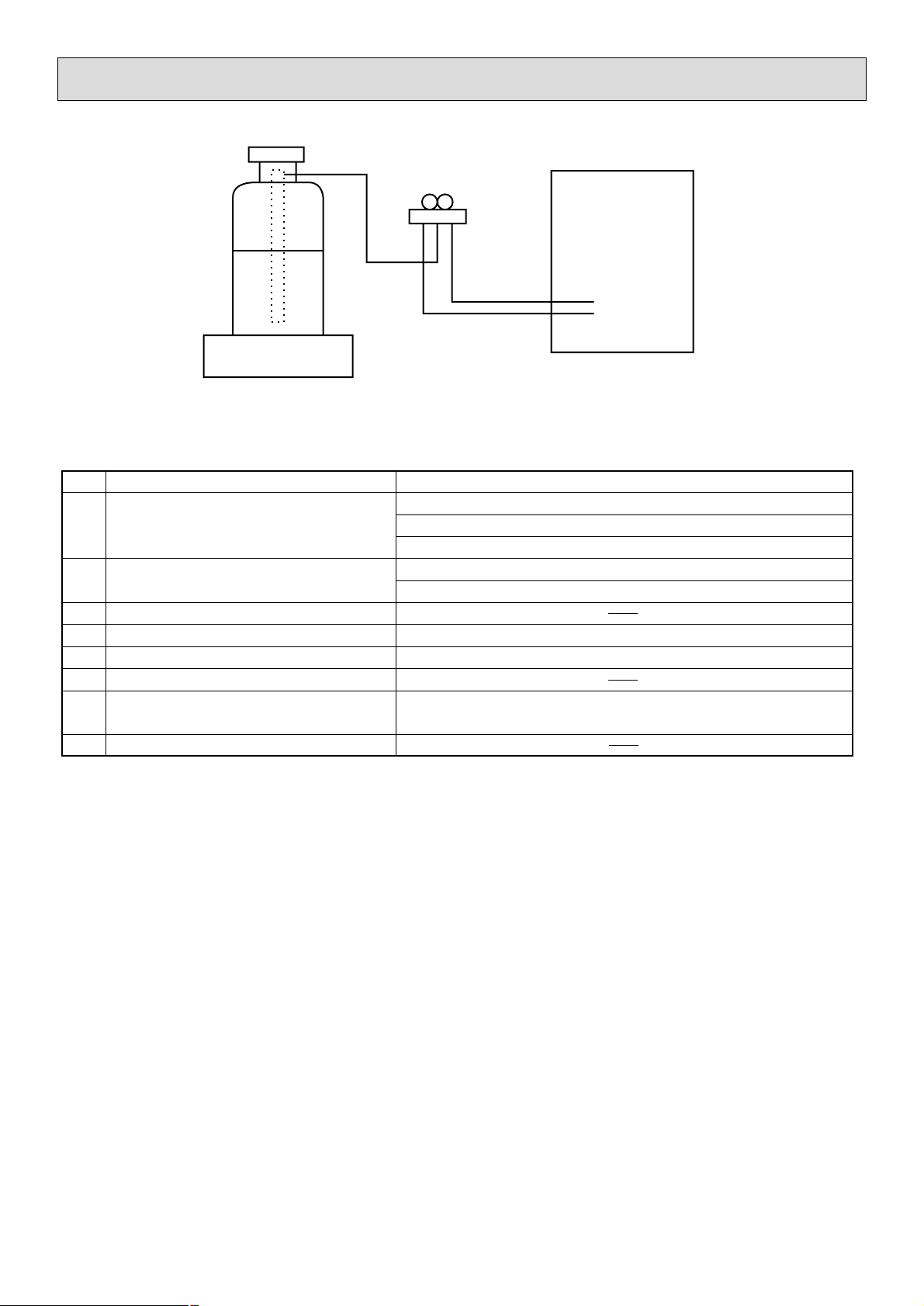
[2] Additional refrigerant charge
When charging directly from cylinder
· Check that cylinder for R410A on the market is syphon type.
· Charging should be performed with the cylinder of syphon stood vertically. (Refr igerant is charged from liquid phase.)
Page 4
- 2 -
Unit
[3] Service tools
Use the below service tools as exclusive tools for R410A refrigerant.
No. Specifications
1 Gauge manifold ·Only for R410A
·Use the existing fitting
specifications
. (UNF1/2)
·Use high-tension side pressure of 5.3MPa·G or over.
2 Charge hose ·Only for R410A
·Use pressure performance of 5.09MPa·G or over.
3 Electronic scale
4 Gas leak detector ·Use the detector for R134a, R407C or R410A.
5 Adaptor for reverse flow check ·Attach on vacuum pump.
6 Refrigerant charge base
7 Refrigerant cylinder ·Only for R410A Top of cylinder (Pink)
Cylinder with syphon
8 Refrigerant recovery equipment
Gravimeter
Page 5
- 3 -
2
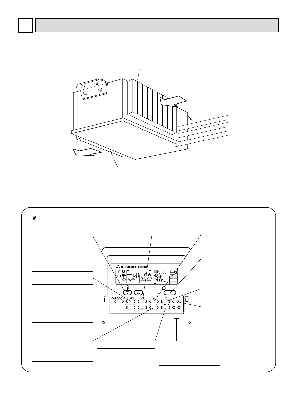
PART NAMES AND FUNCTIONS
● Indoor Unit
PEH-RP8MYA
PEH-RP10MYA
Air intake duct flange
Air outlet duct flange
Air outlet
Air intake
(sucks the air inside the room into the unit)
● Operation buttons
PAR-20MAA
ON/OFF
CENTRALLY CONTROLLED
ERROR CODE
CLOCK
ON OFF
˚C
CHECK
CHECK MODE
FILTER
TEST RUN
FUNCTION
˚C
1Hr.
NOT AVAILABLE
STAND BY
DEFROST
FILTER
CHECK TEST
TEMP.
TIMER SET
This sets the ventilation fan speed.
VENTILATION button
Press this button to switch the cooling,
electronic dry (dehumidify), automatic
and heating modes.
OPERATION SWITCH button
This sets the room temperature. The
temperature setting can be performed
in 1: units
Setting range
Cooling 19: to 30:
Heating 17: to 28:
TEMP. ADJUSTMENT button
This switches between continuous
operation and the timer operation.
TIMER button
This switches between the operation
and stop modes each time it is pressed.
The lamp on this button lights during
operation.
ON/OFF button
Only press this button to perform an
inspection check or test operation.
Do not use it for normal operation.
CHECK-TEST RUN button
This switch the horizontal fan motion
ON and OFF.
(Not available for this model.)
LOUVER button
This adjusts the vertical angle of the
ventilation.
AIR DIRECTION button
This resets the filter service indication
display
FILTER button
This sets the current time, start time
and stop time.
TIME SETTING button
This sets the ventilation fan speed.
FAN SPEED button
(Not available for this model.)
Page 6
- 4 -
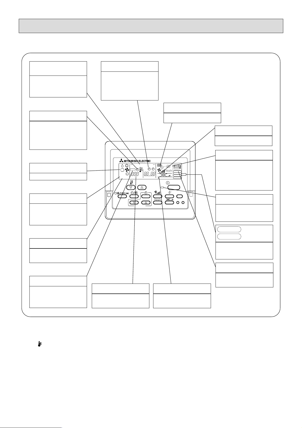
Caution
● Only the Power display lights when the unit is stopped and power supplied to the unit.
● When the central control remote control unit, which is sold separately, is used the ON-OFF button, operation switch button
and TEMP. adjustment button do not operate.
● “NOT AVAILABLE” is displayed when the Air speed button are pressed.This indicates that this room unit is not equipped with
the fan direction adjustment function and the louver function.
● When power is turned ON for the first time, it is normal that “H0” is displayed on the room temperature indication (For max.
2minutes). Please wait until this “H0” indication disappear then start the operation.
CENTRALLY
CONTROLLED display
This indicates when the unit is con-
trolled by optional features such as
central control type remote controller.
TIMER display
This indicates when the continuous
operation and time operation modes
are set.
It also display the time for the timer
operation at the same time as when
it is set.
OPERATION MODE display
This indicates the operation mode.
STANDBY display
The [STANDBY] symbol is only dis-
played from the time the heating
operation starts unit the heated air
begins to blow.
DEFROST display
This indicates when the defrost oper-
ation is performed.
CHECK display
This indicates when a malfunction
has occurred in the unit which should
be checked.
CLOCK display
The current time , start time and stop
time can be displayed in ten second
intervals by pressing the time switch
button.The start time or stop time is
always displayed during the timer
operation.
● Display
In this display example on the bottom left, a condition where all display lamps light is shown for explanation purposes although this differs
from actual operation.
Operation lamp
This lamp lights during operation,
goes off when the unit stops and
flashes when a malfunction occurs.
POWER display
This lamp lights when electricity is
supplied to the unit.
SET TEMPERATURE display
This displays the selected setting
temperature.
AIR DIRECTION display
This displays the air direction.
ROOM TEMPERATURE display
The temperature of the suction air
is displayed during operation.The
display range is 8°C to 39°C.The
display flashes 8°C when the actual
temperature is less than 8°C and
flashes 39°C when the actual temperature is greater than 39°C.
display
This display lights in the check mode
or when a test operation is performed.
CHECK MODE
TEST RUN
This lamp lights when the filter need
to be cleaned.
AIR SPEED display
The selected fan speed is displayed.
FILTER display
PAR-20MAA
ON/OFF
CENTRALLY CONTROLLED
ERROR CODE
CLOCK
ON OFF
˚C
CHECK
CHECK MODE
FILTER
TEST RUN
FUNCTION
˚C
1Hr.
NOT AVAILABLE
STAND BY
DEFROST
FILTER
CHECK TEST
TEMP.
TIMER SET
Page 7
Specifications of air-source heat pump type packaged air conditioner
(Ceiling concealed type indoor unit)
Model name PEH-RP8MYA
PEH-RP8MYAService Ref.
PEH-RP8MYAService Ref.
PUHZ-RP8YHAService Ref.
Outdoor
unit
Indoor unit
Quantity Symbol
Capacity kcal/h
kW
Indoor side Dry bulb temperature/wet bulb temperature
Outdoor side Dry bulb temperature/wet bulb temperature
Power source
Power consumption kW
Operating current A
Remote controller temperature setting range °C
Airflow direction control
Type × Quantity
Airflow rate m
3
/min
External static pressure
Pa
Motor output kW
External finish
Unit (H × W × D) mm
Panel (H × W × D) mm
Heat exchanger type
Air filter
Insulation material
Refrigerant piping size Liquid/Gas
φ
mm
φ
mm
Drain piping size
Noise level dB(A)
Net weight kg
Minimum wire thickness
Circuit breaker
Operation control device (provided)
Decoration panel (Option)
Other mountable major options
Accessories
Special note, Non-standard specifications, etc.
1. The cooling and heating capacities are the maximum capacities that were obtained by operating in the above
air conditions and with a refrigerant pipe of about 5m.
2. The actual capacity characteristics vary with the combination of indoor and outdoor units. See the technical
informaition.
3. The operating noise is the data that was obtained by measuring it 1.5 m from the unit’s bottom in an anechoic
room. (Noise meter A-scale value)
4. The
5. Refer to the service manual of outdoor unit for the outdoor unit’s specifications.
figure of Electrical characteristic, Airflow rate, Noise level, indicates, at 50 Pa setting.
Cooling Heating
16,300 19,300
19.0 (10.0~22.4) 22.4 (10.0~25.0)
27 °C/19 °C 20 °C/–
35 °C/24 °C7 °C/6 ˚C
3N~ 380/400/415V 50Hz
0.65/0.65/0.65 0.65/0.65/0.65
1.12/1.12/1.12 1.12/1.12/1.12
19 ~ 30 17 ~ 28
–
Sirrocco fan × 2
60
50/150
0.75
Galvanizing
428 × 1380 × 650
–
Cross fin
Saran net
Polyethylene foam
9.52/25.4
25.4 (RC1)
49 (at 50 Pa)
70
1.6 mm
15 A
Remote controller: PAR-20MAA
–
–
Electrical characteristics
Fan
External dimension
External wiring
Composing parts
Notes:
Installation manual, Operation manual,
Remote controller
–
Air con-
dition
- 5 -
3
SPECIFICATIONS
Page 8
PEH-RP10MYA
Cooling Heating
18,900 23,200
27 °C/19 °C 20 °C/–
35 °C/24 °C7 °C/ 6 °C
3N~ 380/400/415V 50 Hz
0.94/0.94/0.94 0.94/0.94/0.94
1.64/1.64/1.64 1.64/1.64/1.64
19 ~ 30 17 ~ 28
–
Sirrocco fan × 2
80
50/150
1.23
Galvanizing
428 × 1,580 × 650
–
Cross fin
Saran net
Polyethyene foam
12.7/28.58
25.4 (RC1)
53 (at 50 Pa)
80
1.6 mm
15 A
Remote controller: PAR-20MAA
–
–
Installation manual, Operation manual,
Remote controller
–
PUHZ-RP10YHA
PEH-RP10MYA
PEH-RP10MYA
22.0 (12.5~28.0) 27.0 (15.7~31.5)
Specifications of air-source heat pump type packaged air conditioner
(Ceiling concealed type indoor unit)
Model name
Service Ref.
Service Ref.
Service Ref.
Outdoor
unit
Indoor unit
Quantity Symbol
Capacity kcal/h
kW
Indoor side Dry bulb temperature/wet bulb temperature
Outdoor side Dry bulb temperature/wet bulb temperature
Power source
Power consumption kW
Operating current A
Remote controller temperature setting range °C
Airflow direction control
Type × Quantity
Airflow rate m
3
/min
External static pressure
Pa
Motor output kW
External finish
Unit (H × W × D) mm
Panel (H × W × D) mm
Heat exchanger type
Air filter
Insulation material
Refrigerant piping size Liquid/Gas
φ
mm
φ
mm
Drain piping size
Noise level dB(A)
Net weight kg
Minimum wire thickness
Circuit breaker
Operation control device (provided)
Decoration panel (Option)
Other mountable major options
Accessories
Special note, Non-standard specifications, etc.
1. The cooling and heating capacities are the maximum capacities that were obtained by operating in the above
air conditions and with a refrigerant pipe of about 5m.
2. The actual capacity characteristics vary with the combination of indoor and outdoor units. See the technical
informaition.
3. The operating noise is the data that was obtained by measuring it 1.5 m from the unit’s bottom in an anechoic
room. (Noise meter A-scale value)
4. The
5. Refer to the service manual of outdoor unit for the outdoor unit’s specifications.
figure of Electrical characteristic, Airflow rate, Noise level, indicates, at 50 Pa setting.
Electrical characteristics
Fan
External dimension
External wiring
Composing parts
Notes:
Air condition
- 6 -
Page 9
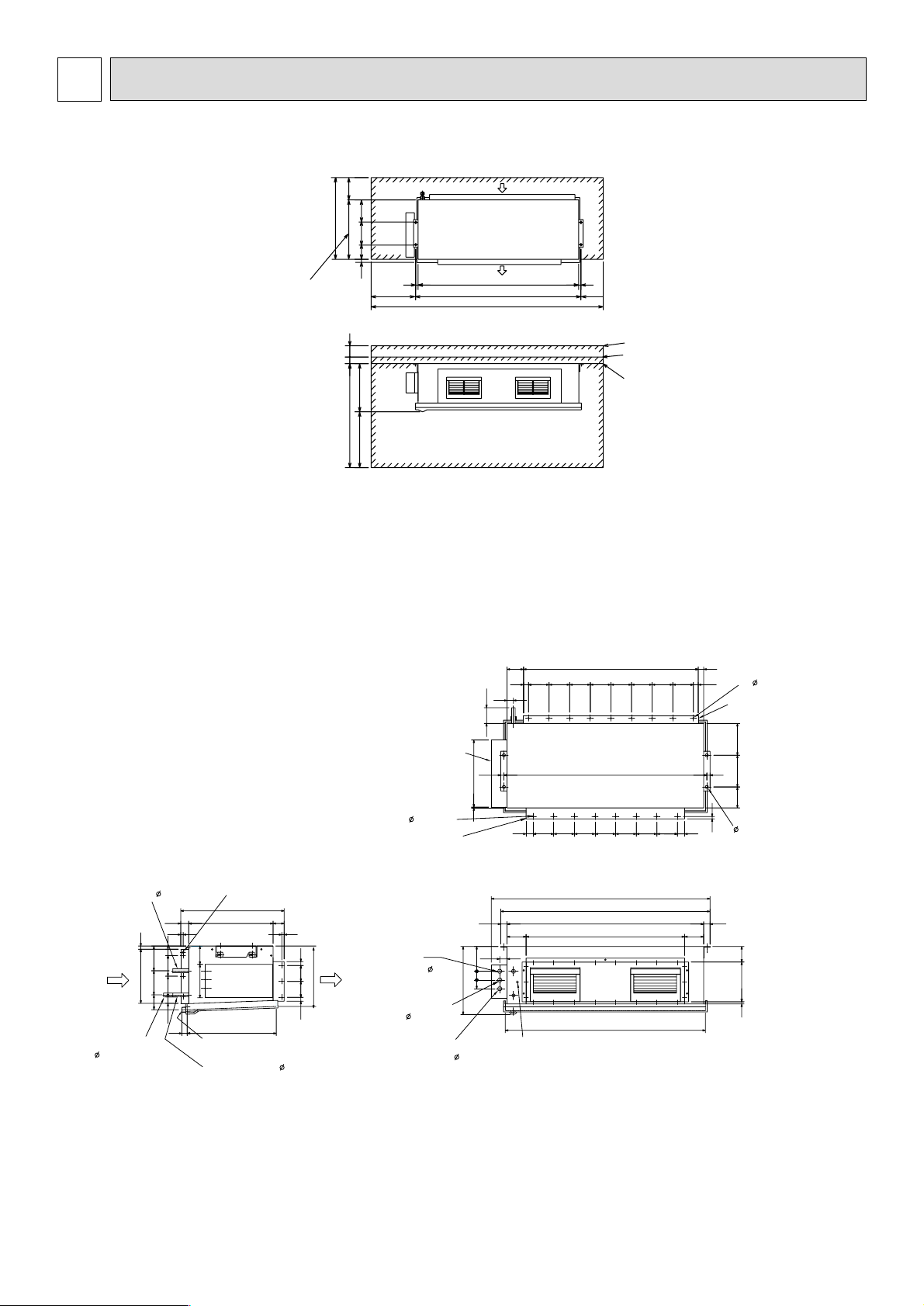
(1) Indoor Unit
• Model PEH-RP8MYA
Note: When connecting duct to the inlet side, remove the air filter attached to the unit body , and mount
an air filter onto the inlet duct side separately.
AIR INLET SENSOR
REFRIGERANT PIPE
12.7
(1/2 BRAZE)
REFRIGERANT PIPE 25.4
(1 BRAZE)
AIR INLET
AIR OUTLET
POWER SUPPLY
WIRING HOLE 27
(AIR INLET SIDE)
CONTROLLER
WIRING HOLE 27
(AIR INLET SIDE)
CONNECT WIRE (PEH-PUH)
WIRING HOLE 27
(AIR INLET SIDE)
ACCESSORY PIPE
(USE FOR ONLY R410A)
9.52 (3/8 BRAZE)
DUCT EARTH POINT
(BOTH DUCT SIDE)
152
650
428
95
156
AIR INLET DUCT
FLANGE
24- 3.1 HOLES
34
31
1102
104
130130130130130130130130
31
344
20
15
7053050
130
130
42
42
DRAIN: Rc 1
CONTROL BOX
4- 12 HOLES
22- 3.1 HOLES
AIR OUTLET DUCT
FLANGE
33
562
382
25 100
100 25
1240
20
20
1280
15
40
120
4513013013013013013013045
40
1320
1000
120
1264
98250
14
(FOR HUNGING
BOLT M10)
<FIELD SUPPLY>
15
100
40
210 116
4235
46
55 55 156
1380
131 200 199
928
1240
20
530
13132
200
199
400
730
200
1280
1880
200
20
428500
25 75
(1)
(2)
(3)
(1) When connecting air inlet
(2) When installing the suspension fixtures prior to installation of the indoor unit without inlet duct
(3) When hanging the indoor unit directly without inlet duct
(A) Service space
(B) Suspension bolt pitch
(C) Air inlet
(D) Air outlet
(A)
(A)
(C)
(B)
(B)
(D)
- 7 -
4
OUTLINE AND DIMENSIONS
Page 10
- 8 -
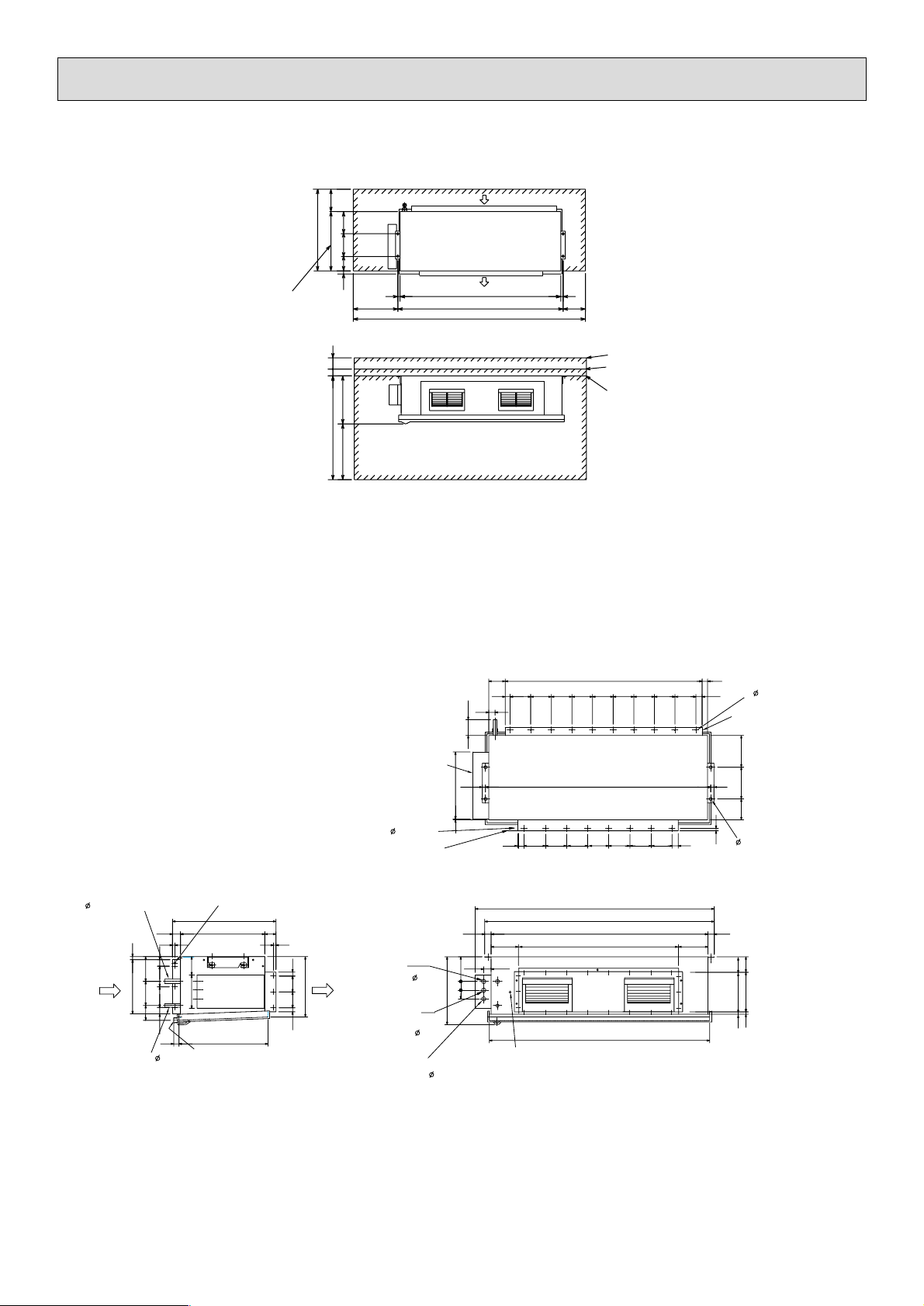
• Model PEH-RP10MYA
Note: When connecting duct to the inlet side, remove the air filter attached to the unit body , and mount
an air filter onto the inlet duct side separately.
(B)
730
200
530
25 75
928
428500
199
200
13132
(A)
400
20
(B)
1440
1480
2080
(C)
(D)
20
200
(1)
(2)
(3)
(A)
(1) When connecting air inlet
(2) When installing the suspension fixtures prior to installation of the indoor unit without inlet duct
(3) When hanging the indoor unit directly without inlet duct
(A) Service space
(B) Suspension bolt pitch
(C) Air inlet
(D) Air outlet
REFRIGERANT PIPE
28.6 (1-1/8 BRAZE)
15
20
42
156
130
344
152
AIR INLET
REFRIGERANT PIPE
(1/2 BRAZE)
130
95
42
33
12.7
AIR INLET SENSOR
650
210 116
562
DRAIN: Rc 1
104
66
40
100
1302
130130130130130130130130
34
130
66
26- 3.1 HOLES
AIR INLET DUCT
FLANGE
CONTROL BOX
20
423
FLANGE
5
45
130
40
220
46
428
55 55 156
DUCT EARTH POINT
(BOTH DUCT SIDE)
22- 3.1 HOLES
AIR OUTLET DUCT
7053050
15
CONTROLLER
100 25
25 100
382
AIR OUTLET
WIRING HOLE 27
(AIR INLET SIDE)
CONNECT WIRE
(PEH-PUH)
WIRING HOLE 27
(AIR INLET SIDE)
POWER SUPPLY
WIRING HOLE 27
(AIR INLET SIDE)
1480
130
1580
1520
1440 40
1000
1464
20
131 200 199
45130130130130
220
15
4- 12 HOLES
(FOR HUNGING
<FIELD SUPPLY>
98
250
14
BOLT M10)
130
Page 11

(2) Remote Controller
• Model
PAR-20MAA
- 9 -
120
(Front view) (Side view) (Rear view)
130
19
83.5
46
Page 12

(1) Indoor Unit
• Models PEH-RP8MYA/RP10MYA
INDOOR UNIT
SYMBOL NAME
MF1 FAN MOTOR (INDOOR)
51F OVER CURRENT RELAY (INDOOR FAN MOTOR)
52F CONTACTOR (INDOOR FAN MOTOR)
49F INTERNAL THERMOSTAT (INDOOR FAN MOTOR)
TB2, 4, 5 TERMINAL BLOCK
TH1 ROOM TEMP. (0˚C/15kΩ, 25˚C/5.4kΩ)
TH2 THERMISTOR PIPE TEMP. (0˚C/15kΩ, 25˚C/5.4kΩ)
TH5 COND./EVA. TEMP. (0˚C/15kΩ, 25˚C/5.4kΩ)
F1 FUSE (4A 250VAC CLASS T)
ZNR VARISTOR
X4-6 AUXILIARY RELAY (INDOOR CONTROLLER BOARD)
SW1 SWITCH (MODEL SELECTION)
SW2 SWITCH (CAPACITY CORD)
SWE SWITCH (EMERGENCY OPERATION)
LED1 LED (POWER SUPPLY : INDOOR CONTROLLER BOARD)
LED2 LED (POWER SUPPLY : REMOTE CONTROLLER)
LED3 LED (TRANSMISSION : INDOOR-OUTDOOR)
CR SURGE KILLER
CN03, CN21, 2D
CN20-22, 29, 32
CONNECTOR (INDOOR CONTROLLER BOARD)
CN41, 90, FAN
CN01, 02, 2S CONNECTOR (INDOOR POWER BOARD)
C01, 02, 12 CONNECTOR (FAN MOTOR)
FB FERRITE CORE
OUTDOOR UNIT
SYMBOL NAME
TB3 TERMINAL BLOCK
REMOTE CONTROLLER
SYMBOL NAME
TB6 TERMINAL BLOCK
Note:
1. The dotted lines show field wiring.
2. Color of earth wire is yellow and green twisting.
3. Specification subject to change without notice.
4. Indoor and outdoor connecting wires are made with
polarities, make sure matching wiring and terminal.
5. Emergency operation
If a trouble occurs with either the remote controller
or the indoor microcomputer and no other trouble
exisits, emergency operation for cooling or heating
can be performed by changing the setting of switch
(SWE) on the indoor controller board.
6. SW2 is shown PEH-RP10MYA setting.
In case of PEH-RP8MYA setting is shown as below.
Caution:
1. To protect fan motor from abnor mal current,over
current relays is installed.
Therefore, do not change factory set value of over
current relays.
SW2
ON
OFF
4321
PE
- 10 -
5
ELECTRICAL WIRING DIA GRAM
REMOTE CONTROLLER
REMOTE CONTROLLER
BOARD
LCD
CN
T B 6
CIRCUIT BREAKER
(FIELD SUPPLY)
PEH-RP8,10MYA:15A
POWER SUPPLY
3N~PE
380/400/415V
50Hz
C0
5 2 F 5 1 F
1
CN2
2
1
CN2
2
2 1
(WHITE)
(50Pa)
INDOO
CONTROLLER
1
2
CN9
3
4
5
6
7
8
9
CN2
D C 14V
F B
INDOO
POWER BOARD
CN2S
D C 14V
1
2
14V
T B 2
L 1
RED
L 2
WHITE
L 3
BLACK
N
PE
T B 5
1
2
PE
INLET
DUCT
PE
OUTLET
PE
PE
DUCT
INDOOR UNIT [PEH-RP8, RP10MYA]
C02
PE
(RED)
(150Pa)
2
1
MF1
3
2
1
3
1
2
3
5 3 1
4
1
2
1
2
1
2
C R
DC
CN01
ZNR
1
2
CN3
3
L E D 1
L E D 2
L E D 3
1 2 3
F1
CN03
1
2
3
CN02
CN41
CN29
CN21
CN20
FAN
4 9 F
5 1 F
T H 1
T H 2
T H 5
4
SW
4321
SW
SW
X4 X5 X6
7 5 3 1
52F
1
C12
3
1235
ON
OFF
ON
OFF
ON
OFF
X6X5X4
T B 4
S 1
S 2
S 3
TO OUTDOOR
CONNECTING
(POLER)
POWER
3N~
380/400/415V
OUTDOOR UNIT
T B 3
S1
S2
S3
T B 1
L1
L2
L3
N
PE
Page 13

50 55 60 65
70
Capacity/Input ratio
Airflow rate (m3/min)
1.0
1.05
0.95
Cooling
Capacity/Input ratio
Heating
Airflow rate (m3/min)
50 55
60 65 70
1.0
1.05
0.95
Input
Capacity
Capacity
Input
[1] Capacity/Input Ratio against Changes in Room Airflow Rate
• Model PEH-RP8MYA
• Model
PEH-RP10MYA
- 11 -
6
TECHNICAL DATA
Cooling
1.05
1.0
Input
Capacity/Input ratio
Capacity
0.95
70 75 80 85
Airflow rate (m3/min)
1.05
Heating
Input
1.0
Capacity
Capacity/Input ratio
0.95
90
70 75 80 85
Airflow rate (m3/min)
90
Page 14

[2] Capacity table
COOLING CAPACITY (1)
PEH-RP8MYA/PUHZ-RP8YHA (Indoor unit Airflow rate 60m
3
/min)
Outdoor intake air DB˚C
2520
CA
SHC(W)
SHF P.C. CA
SHC(W)
SHF P.C. CA
SHC(W)
SHF P.C.
18810
20140
21660
18810
20140
21660
18810
20140
21660
23085
18810
20140
21660
23085
18810
20140
21660
23085
18810
20140
21660
23085
18810
20140
21660
23085
18810
20140
21660
23085
18810
20140
21660
23085
12227
10674
8881
13731
12285
10613
15236
13897
12346
10388
16741
15508
14079
12235
17493
16313
14945
13158
18246
17119
15812
14082
18810
18730
17545
15929
18810
20140
19277
17775
18810
20140
21010
19622
20
22
24
26
27
28
30
32
34
16
18
20
16
18
20
16
18
20
22
16
18
20
22
16
18
20
22
16
18
20
22
16
18
20
22
16
18
20
22
16
18
20
22
0.65
0.53
0.41
0.73
0.61
0.49
0.81
0.69
0.57
0.45
0.89
0.77
0.65
0.53
0.93
0.81
0.69
0.57
0.97
0.85
0.73
0.61
1.00
0.93
0.81
0.69
1.00
1.00
0.89
0.77
1.00
1.00
0.97
0.85
5.82
5.93
6.12
5.82
5.93
6.12
5.82
5.93
6.12
6.26
5.82
5.93
6.12
6.26
5.82
5.93
6.12
6.26
5.82
5.93
6.12
6.26
5.82
5.93
6.12
6.26
5.82
5.93
6.12
6.26
5.82
5.93
6.12
6.26
18240
19570
21185
18240
19570
21185
18240
19570
21185
22610
18240
19570
21185
22610
18240
19570
21185
22610
18240
19570
21185
22610
18240
19570
21185
22610
18240
19570
21185
22610
18240
19570
21185
22610
11856
10372
8686
13315
11938
10381
14774
13503
12075
10175
16234
15069
13770
11983
16963
15852
14618
12888
17693
16635
15465
13792
18240
18200
17160
15601
18240
19570
18855
17410
18240
19570
20549
19219
0.65
0.53
0.41
0.73
0.61
0.49
0.81
0.69
0.57
0.45
0.89
0.77
0.65
0.53
0.93
0.81
0.69
0.57
0.97
0.85
0.73
0.61
1.00
0.93
0.81
0.69
1.00
1.00
0.89
0.77
1.00
1.00
0.97
0.85
6.15
6.26
6.41
6.15
6.26
6.41
6.15
6.26
6.41
6.62
6.15
6.26
6.41
6.62
6.15
6.26
6.41
6.62
6.15
6.26
6.41
6.62
6.15
6.26
6.41
6.62
6.15
6.26
6.41
6.62
6.15
6.26
6.41
6.62
17670
18905
20615
17670
18905
20615
17670
18905
20615
22040
17670
18905
20615
22040
17670
18905
20615
22040
17670
18905
20615
22040
17670
18905
20615
22040
17670
18905
20615
22040
17670
18905
20615
22040
11486
10020
8452
12899
11532
10101
14313
13044
11751
9918
15726
14557
13400
11681
16433
15313
14224
12563
17140
16069
15049
13444
17670
17582
16698
15208
17670
18905
18347
16971
17670
18905
19997
18734
0.65
0.53
0.41
0.73
0.61
0.49
0.81
0.69
0.57
0.45
0.89
0.77
0.65
0.53
0.93
0.81
0.69
0.57
0.97
0.85
0.73
0.61
1.00
0.93
0.81
0.69
1.00
1.00
0.89
0.77
1.00
1.00
0.97
0.85
6.52
6.70
6.84
6.52
6.70
6.84
6.52
6.70
6.84
7.06
6.52
6.70
6.84
7.06
6.52
6.70
6.84
7.06
6.52
6.70
6.84
7.06
6.52
6.70
6.84
7.06
6.52
6.70
6.84
7.06
6.52
6.70
6.84
7.06
Indoor
intake air
DB˚C
Indoor
intake air
WB˚C
30
NOTE: CA : Capacity (W) SHC : Sensible heat capacity (W)
P.C. : Power consumption (kW)
SHF
: Sensible heat factor
- 12 -
Page 15

COOLING CAPACITY (2)
PEH-RP8MYA/PUHZ-RP8YHA (Indoor unit Airflow rate 60m
3
/min)
Outdoor intake air DB˚C
4035
CA
SHC(W)
SHF P.C. CA
SHC(W)
SHF P.C. CA
SHC(W)
SHF P.C.
16910
18240
19760
16910
18240
19760
16910
18240
19760
21280
16910
18240
19760
21280
16910
18240
19760
21280
16910
18240
19760
21280
16910
18240
19760
21280
16910
18240
19760
21280
16910
18240
19760
21280
10992
9667
8102
12344
11126
9682
13697
12586
11263
9576
15050
14045
12844
11278
15726
14774
13634
12130
16403
15504
14425
12981
16910
16963
16006
14683
16910
18240
17586
16386
16910
18240
19167
18088
20
22
24
26
27
28
30
32
34
16
18
20
16
18
20
16
18
20
22
16
18
20
22
16
18
20
22
16
18
20
22
16
18
20
22
16
18
20
22
16
18
20
22
0.65
0.53
0.41
0.73
0.61
0.49
0.81
0.69
0.57
0.45
0.89
0.77
0.65
0.53
0.93
0.81
0.69
0.57
0.97
0.85
0.73
0.61
1.00
0.93
0.81
0.69
1.00
1.00
0.89
0.77
1.00
1.00
0.97
0.85
6.99
7.17
7.35
6.99
7.17
7.35
6.99
7.17
7.35
7.50
6.99
7.17
7.35
7.50
6.99
7.17
7.35
7.50
6.99
7.17
7.35
7.50
6.99
7.17
7.35
7.50
6.99
7.17
7.35
7.50
6.99
7.17
7.35
7.50
16150
17670
19000
16150
17670
19000
16150
17670
19000
20520
16150
17670
19000
20520
16150
17670
19000
20520
16150
17670
19000
20520
16150
17670
19000
20520
16150
17670
19000
20520
16150
17670
19000
20520
10498
9365
7790
11790
10779
9310
13082
12192
10830
9234
14374
13606
12350
10876
15020
14313
13110
11696
15666
15020
13870
12517
16150
16433
15390
14159
16150
17670
16910
15800
16150
17670
18430
17442
0.65
0.53
0.41
0.73
0.61
0.49
0.81
0.69
0.57
0.45
0.89
0.77
0.65
0.53
0.93
0.81
0.69
0.57
0.97
0.85
0.73
0.61
1.00
0.93
0.81
0.69
1.00
1.00
0.89
0.77
1.00
1.00
0.97
0.85
7.50
7.72
7.86
7.50
7.72
7.86
7.50
7.72
7.86
8.08
7.50
7.72
7.86
8.08
7.50
7.72
7.86
8.08
7.50
7.72
7.86
8.08
7.50
7.72
7.86
8.08
7.50
7.72
7.86
8.08
7.50
7.72
7.86
8.08
15390
16530
17860
15390
16530
17860
15390
16530
17860
19380
15390
16530
17860
19380
15390
16530
17860
19380
15390
16530
17860
19380
15390
16530
17860
19380
15390
16530
17860
19380
15390
16530
17860
19380
10004
8761
7323
11235
10083
8751
12466
11406
10180
8721
13697
12728
11609
10271
14313
13389
12323
11047
14928
14051
13038
11822
15390
15373
14467
13372
15390
16530
15895
14923
15390
16530
17324
16473
0.65
0.53
0.41
0.73
0.61
0.49
0.81
0.69
0.57
0.45
0.89
0.77
0.65
0.53
0.93
0.81
0.69
0.57
0.97
0.85
0.73
0.61
1.00
0.93
0.81
0.69
1.00
1.00
0.89
0.77
1.00
1.00
0.97
0.85
8.12
8.30
8.44
8.12
8.30
8.44
8.12
8.30
8.44
8.59
8.12
8.30
8.44
8.59
8.12
8.30
8.44
8.59
8.12
8.30
8.44
8.59
8.12
8.30
8.44
8.59
8.12
8.30
8.44
8.59
8.12
8.30
8.44
8.59
Indoor
intake air
DB˚C
Indoor
intake air
WB˚C
45
NOTE: CA : Capacity (W) SHC : Sensible heat capacity (W)
P.C. : Power consumption (kW)
SHF
: Sensible heat factor
- 13 -
Page 16

COOLING CAPACITY (3)
PEH-RP10MYA/PUHZ-RP10YHA (Indoor unit Airflow rate 80m
3
/min)
NOTE: CA : Capacity (W) SHC : Sensible heat capacity (W)
P.C. : Power consumption (kW)
SHF
: Sensible heat factor
Outdoor intake air DB˚C
2520
CA
SHC(W)
SHF P.C. CA
SHC(W)
SHF P.C. CA
SHC(W)
SHF P.C.
21780
23320
25080
21780
23320
25080
21780
23320
25080
26730
21780
23320
25080
26730
21780
23320
25080
26730
21780
23320
25080
26730
21780
23320
25080
26730
21780
23320
25080
26730
21780
23320
25080
26730
15682
13992
12038
17424
15858
14045
19166
17723
16051
13900
20909
19589
18058
16038
21780
20522
19061
17107
21780
21454
20064
18176
21780
23320
22070
20315
21780
23320
24077
22453
21780
23320
25080
24592
20
22
24
26
27
28
30
32
34
16
18
20
16
18
20
16
18
20
22
16
18
20
22
16
18
20
22
16
18
20
22
16
18
20
22
16
18
20
22
16
18
20
22
0.72
0.60
0.48
0.80
0.68
0.56
0.88
0.76
0.64
0.52
0.96
0.84
0.72
0.60
1.00
0.88
0.76
0.64
1.00
0.92
0.80
0.68
1.00
1.00
0.88
0.76
1.00
1.00
0.96
0.84
1.00
1.00
1.00
0.92
6.74
6.87
7.08
6.74
6.87
7.08
6.74
6.87
7.08
7.25
6.74
6.87
7.08
7.25
6.74
6.87
7.08
7.25
6.74
6.87
7.08
7.25
6.74
6.87
7.08
7.25
6.74
6.87
7.08
7.25
6.74
6.87
7.08
7.25
21120
22660
24530
21120
22660
24530
21120
22660
24530
26180
21120
22660
24530
26180
21120
22660
24530
26180
21120
22660
24530
26180
21120
22660
24530
26180
21120
22660
24530
26180
21120
22660
24530
26180
15206
13596
11774
16896
15409
13737
18586
17222
15699
13614
20275
19034
17662
15708
21120
19941
18643
16755
21120
20847
19624
17802
21120
22660
21586
19897
21120
22660
23549
21991
21120
22660
24530
24086
0.72
0.60
0.48
0.80
0.68
0.56
0.88
0.76
0.64
0.52
0.96
0.84
0.72
0.60
1.00
0.88
0.76
0.64
1.00
0.92
0.80
0.68
1.00
1.00
0.88
0.76
1.00
1.00
0.96
0.84
1.00
1.00
1.00
0.92
7.12
7.25
7.42
7.12
7.25
7.42
7.12
7.25
7.42
7.67
7.12
7.25
7.42
7.67
7.12
7.25
7.42
7.67
7.12
7.25
7.42
7.67
7.12
7.25
7.42
7.67
7.12
7.25
7.42
7.67
7.12
7.25
7.42
7.67
20460
21890
23870
20460
21890
23870
20460
21890
23870
25520
20460
21890
23870
25520
20460
21890
23870
25520
20460
21890
23870
25520
20460
21890
23870
25520
20460
21890
23870
25520
20460
21890
23870
25520
14731
13134
11458
16368
14885
13367
18005
16636
15277
13270
19642
18388
17186
15312
20460
19263
18141
16333
20460
20139
19096
17354
20460
21890
21006
19395
20460
21890
22915
21437
20460
21890
23870
23478
0.72
0.60
0.48
0.80
0.68
0.56
0.88
0.76
0.64
0.52
0.96
0.84
0.72
0.60
1.00
0.88
0.76
0.64
1.00
0.92
0.80
0.68
1.00
1.00
0.88
0.76
1.00
1.00
0.96
0.84
1.00
1.00
1.00
0.92
7.54
7.76
7.92
7.54
7.76
7.92
7.54
7.76
7.92
8.18
7.54
7.76
7.92
8.18
7.54
7.76
7.92
8.18
7.54
7.76
7.92
8.18
7.54
7.76
7.92
8.18
7.54
7.76
7.92
8.18
7.54
7.76
7.92
8.18
Indoor
intake air
DB˚C
Indoor
intake air
WB˚C
30
- 14 -
Page 17

COOLING CAPACITY (4)
PEH-RP10MYA/PUHZ-RP10YHA (Indoor unit Airflow rate 80m
3
/min)
Outdoor intake air DB˚C
4035
CA
SHC(W)
SHF P.C. CA
SHC(W)
SHF P.C. CA
SHC(W)
SHF P.C.
19580
21120
22880
19580
21120
22880
19580
21120
22880
24640
19580
21120
22880
24640
19580
21120
22880
24640
19580
21120
22880
24640
19580
21120
22880
24640
19580
21120
22880
24640
19580
21120
22880
24640
14098
12672
10982
15664
14362
12813
17230
16051
14643
12813
18797
17741
16474
14784
19580
18586
17389
15770
19580
19430
18304
16755
19580
21120
20134
18726
19580
21120
21965
20698
19580
21120
22880
22669
20
22
24
26
27
28
30
32
34
16
18
20
16
18
20
16
18
20
22
16
18
20
22
16
18
20
22
16
18
20
22
16
18
20
22
16
18
20
22
16
18
20
22
0.72
0.60
0.48
0.80
0.68
0.56
0.88
0.76
0.64
0.52
0.96
0.84
0.72
0.60
1.00
0.88
0.76
0.64
1.00
0.92
0.80
0.68
1.00
1.00
0.88
0.76
1.00
1.00
0.96
0.84
1.00
1.00
1.00
0.92
8.09
8.30
8.51
8.09
8.30
8.51
8.09
8.30
8.51
8.68
8.09
8.30
8.51
8.68
8.09
8.30
8.51
8.68
8.09
8.30
8.51
8.68
8.09
8.30
8.51
8.68
8.09
8.30
8.51
8.68
8.09
8.30
8.51
8.68
18700
20460
22000
18700
20460
22000
18700
20460
22000
23760
18700
20460
22000
23760
18700
20460
22000
23760
18700
20460
22000
23760
18700
20460
22000
23760
18700
20460
22000
23760
18700
20460
22000
23760
13464
12276
10560
14960
13913
12320
16456
15550
14080
12355
17952
17186
15840
14256
18700
18005
16720
15206
18700
18823
17600
16157
18700
20460
19360
18058
18700
20460
21120
19958
18700
20460
22000
21859
0.72
0.60
0.48
0.80
0.68
0.56
0.88
0.76
0.64
0.52
0.96
0.84
0.72
0.60
1.00
0.88
0.76
0.64
1.00
0.92
0.80
0.68
1.00
1.00
0.88
0.76
1.00
1.00
0.96
0.84
1.00
1.00
1.00
0.92
8.68
8.94
9.10
8.68
8.94
9.10
8.68
8.94
9.10
9.36
8.68
8.94
9.10
9.36
8.68
8.94
9.10
9.36
8.68
8.94
9.10
9.36
8.68
8.94
9.10
9.36
8.68
8.94
9.10
9.36
8.68
8.94
9.10
9.36
17820
19140
20680
17820
19140
20680
17820
19140
20680
22440
17820
19140
20680
22440
17820
19140
20680
22440
17820
19140
20680
22440
17820
19140
20680
22440
17820
19140
20680
22440
17820
19140
20680
22440
12830
11484
9926
14256
13015
11581
15682
14546
13235
11669
17107
16078
14890
13464
17820
16843
15717
14362
17820
17609
16544
15259
17820
19140
18198
17054
17820
19140
19853
18850
17820
19140
20680
20645
0.72
0.60
0.48
0.80
0.68
0.56
0.88
0.76
0.64
0.52
0.96
0.84
0.72
0.60
1.00
0.88
0.76
0.64
1.00
0.92
0.80
0.68
1.00
1.00
0.88
0.76
1.00
1.00
0.96
0.84
1.00
1.00
1.00
0.92
9.40
9.61
9.78
9.40
9.61
9.78
9.40
9.61
9.78
9.95
9.40
9.61
9.78
9.95
9.40
9.61
9.78
9.95
9.40
9.61
9.78
9.95
9.40
9.61
9.78
9.95
9.40
9.61
9.78
9.95
9.40
9.61
9.78
9.95
Indoor
intake air
DB˚C
Indoor
intake air
WB˚C
45
NOTE: CA : Capacity (W) SHC : Sensible heat capacity (W)
P.C. : Power consumption (kW)
SHF
: Sensible heat factor
- 15 -
Page 18

HEATING CAPACITY
PUHZ-RP8YHA/PUHZ-RP10YHA
Cooling capacity correction factors
Heaing capacity correction factors
[3] CORRECTION FACTORS
Outdoor intake air WB˚C
-5
CA P.C. CA P.C. CA P.C.
14224
13664
13216
17145
16470
15930
4.12
4.47
4.75
4.96
5.38
5.72
PEH-RP8MYA
(Airflow Rate
60m
3
/min)
PEH-RP10MYA
(Airflow Rate
80m
3
/min)
15
20
25
15
20
25
15456
14784
14336
18630
17820
17280
4.54
4.89
5.30
5.47
5.89
6.39
17248
16352
15680
20790
19710
18900
5.24
5.65
6.14
6.31
6.81
7.40
Service Ref.
Indoor
intake air
DB˚C
0-10
Refrigerent piping length (one way)
5m 10m 15m 20m 25m 30m 35m 40m
1.00
1.00
0.985
0.985
PEH-RP8MYA
PEH-RP10MYA
0.971
0.971
0.958
0.958
0.943
0.943
0.931
0.931
0.919
0.919
0.908
0.908
Service Ref.
Refrigerent piping length (one way)
45m 50m 55m 60m
PEH-RP8MYA
PEH-RP10MYA
0.898
0.898
0.887
0.887
0.876
0.876
0.865
0.865
Service Ref.
65m 70m
0.855
0.855
0.847
0.847
75m 80m
0.838
0.838
0.829
0.829
Refrigerent piping length (one way)
5m 10m 15m 20m 25m 30m 35m 40m
1.00
1.00
0.997
0.997
PEH-RP8MYA
PEH-RP10MYA
0.994
0.994
0.991
0.991
0.988
0.988
0.985
0.985
0.982
0.982
0.979
0.979
Service Ref.
Refrigerent piping length (one way)
45m 50m 55m 60m
PEH-RP8MYA
PEH-RP10MYA
0.976
0.976
0.973
0.973
0.970
0.970
0.967
0.967
Service Ref.
65m 70m
0.964
0.964
0.961
0.961
75m 80m
0.958
0.958
0.955
0.955
Outdoor intake air WB˚C
5
CA P.C. CA P.C. CA P.C.
PEH-RP8MYA
(Airflow Rate
60m
3
/min)
PEH-RP10MYA
(Airflow Rate
80m
3
/min)
15
20
25
15
20
25
22624
21840
20608
27270
26325
24840
6.28
6.77
7.19
7.57
8.16
8.66
25536
24640
23744
30780
29700
28620
6.98
7.54
8.06
8.41
9.08
9.71
28448
27440
26432
34290
33075
31860
7.54
8.10
8.69
9.08
9.76
10.47
Service Ref.
Indoor
intake air
DB˚C
1510
NOTE: CA : Capacity (W) P.C. : Power consumption (kW)
- 16 -
Page 19

External static pressure (Pa)
40 50 60 70 80
50
0
200
Operating airflow range
Airflow rate (m
3
/min)
100
150
220
External static pressure (Pa)
60 70 80 90 100
50
0
200
Operating airflow range
Airflow rate (m
3
/min)
100
150
220
PEH-RP8MYA
PEH-RP10MYA
[4] Airflow Characteristic Curves
[5] Center of Gravity (Indoor unit)
Item
Model name
PEH-RP8MYA
PEH-RP10MYA
Center of gravity
X
630
730
Y
230
235
Z
240
240
unit : (mm)
X
Y
Z
Top of the unit
• Models PEH-RP8MYA/RP10MYA
- 17 -
Page 20

[6] Standard Operation Data
The unit of pressure has been charged to MPa based on international SI system.
The converesion factor is : 1(MPa)=10.2(kgf/cm
2
)
PEH-RP10MYAPEH-RP8MYA
PEH-RP10MYAPEH-RP8MYAIndoor unit Service Ref.
3, 503, 50
400400
0.940.65
1.641.12
PUHZ-RP10YHAPUHZ-RP8YHA
3, 503, 50
400400
V
kW
A
V
HeatingCoolingHeatingCooling
Service Ref.
Mode
11.9812.0110.1510.63
67.170.271.373.0
38.747.841.447.1
3.014.64.712.2
5555
20272027
15191519
37.015.338.814.7
735735
624624
D.B.
W.B.
D.B.
D.B.
W.B.
–0.82–0.75
–0.15–0.18
SHF
BF
2.27
(23.2)
2.86
(29.2)
2.59
(26.4)
2.81
(28.7)
0.63
(6.4)
0.96
(9.8)
0.69
(7.0)
0.92
(9.4)
Phase, Hz
Volts
Input
Current
Outdoor unit Service Ref.
Phase, Hz
Volts
Current
Discharge temreature
Condensing temreature
Suction temreature
Ref. pipe length
Intake air temreature
Discharge air temreature
Intake air temreature
Discharge pressure
Suction pressure
A
˚C
˚C
˚C
m
˚C
˚C
˚C
˚C
˚C
MPa
(kgf/cm
2
)
MPa
(kgf/cm2)
Outdoor
side
Indoor
side
Refrigerant circuit Electrical circuit
- 18 -
Page 21

[7] NC Curve (Indoor unit)
PEH-RP8MYA
Measurement condition
PEH-RP10MYA
Measurement condition
OCTAVE BAND CENTER FREQUENCIES <Hz>
OCTAVE BAND PRESSURE LEVEL <dB> 0dB = 20
µPa
OCTAVE BAND CENTER FREQUENCIES <Hz>
OCTAVE BAND PRESSURE
LEVEL
<dB>
0dB = 20
µPa
- 19 -
Aux. duct
1m 2m
1.5m
Measured point
70
External static pressure: 50Pa
60
50
40
30
20
Approximate minimum
audible limit on
continuous noise
10
63 125 250 500 1000 2000 4000 8000
External static pressure: 150Pa
NC60
NC50
NC40
NC30
NC20
Aux. duct
1m 2m
Measured point
1.5m
70
External static pressure: 50Pa
60
External static pressure: 150Pa
50
40
30
20
Approximate minimum
audible limit on
continuous noise
10
63 125 250 500 1000 2000 4000 8000
NC60
NC50
NC40
NC30
NC20
Page 22

[1] Appearance of Equipment
• PEH-RP8MYA/RP10MYA Electrical Parts Box (with cover removed)
Terminal bed
(indoor/outdoor connecting line)
Terminal bed (power)
Over current relay
(fan motor)
Indoor power board
Magnetic contactor (fan motor)
Terminal bed
(remote controller transmission line)
Indoor circuit board
- 20 -
7
SERVICE DATA
Page 23

[2] Internal Construction
• PEH-RP8MYA/RP10MYA (Indoor unit)
Refrigerant piping flange connection : LP øA
Refrigerant piping flare connection : HP
ø
B
Leg
(for installation)
Duct flange
Air filter
Heat exchanger
Fan motor
Sirrocco fan
Drian connection (R1)
Electrical parts box
Drain pan
Model name
PEH-RP8MYA
PEH-RP10MYA
A
25.4
28.58
B
9.52
12.7
[3] Refrigerant Circuit
Brazing connection
Indoor Heat exchanger
Cooling operation
Heating operation
- 21 -
Page 24

[1] DIP SW1 for model Selection (DIP SW1 has been set at factory)
PEH-RP8MYA/RP10MYA : SW1-1, -4 ON, SW1-2, -3, -5 OFF
[2] DIP SW2 for Capacity Setting (DIP SW2 has been set at factory)
PEH-RP8MYA : SW2-1, -2, -3 and, -4 OFF
[3] DIP SWE for Emergency Operation
When SWE is turned ON, FAN turns ON. Setting of emergency operation other than SWE is
performed at the outdoor unit. For a description of the specific emergency operation execution
method, refer to the outdoor unit (PUHZ-RP8YHA, PUHZ-RP10YHA) Technical & Service Manual.
ON
OFF
54321
ON
OFF
4321
ON
OFF
PEH-RP10MYA : SW2-1 ON, SW2-2, -3, and, -4 OFF
ON
OFF
4321
- 22 -
8
FUNCTION OF SWITCH ON INDOOR CIRCUIT BOARD
Page 25

[1] Before test run
The test run can be carried out either from the outdoor unit or the indoor unit.
1. Check list
• After the installation, piping setup,and wiring of the indoor and outdoor units is complete, check that refrigerant is not
leaking, the power and control wires are not loose, and the poles are not reversed.
• Use a 500 V insulation resistance tester to make sure that the resistance between the power terminal and the ground
is 1.0 M or more. If it is less than 1.0 M, do not operate the unit. *Absolutely do not touch the tester to indoor/outdoor
connection terminals S1, S2, and S3. An accident could occur.
• Make sure there is no malfunction in the outdoor
unit. (If there is a malfunction, y ou can diagnose it using LED2 on the
board.)
• Check that the ball valve is fully open on both the liquid and gas ends.
• Check the electrical power phase. If the phase is reversed, the fan may rotate in the wrong direction or stop, or
unusual sounds may be produced.
• Starting at least 12 hours before the test run,send current through the crankcase heater. (If the current is running f or
a shorter period of time, damage to the compressor could result.)
• For specific models requiring changing of settings for higher ceilings or selection of power supply ON/OFF capability,
make proper changes referring to the description for Selection of Functions through Remote Controller.
After the above checks are complete, carry out the test run as indicated in the following outline.
[2] Test run procedures
1. Indoor unit
Operating procedures
(1) Turn on the main power supply
While the room temperature display on the remote controller reads “CENTRALLY CONTROLLED”, the remote
controller is disabled.Turn off the “CENTRALLY CONTROLLED” display before using the remote controller.
(2) Press “TEST RUN” button twice
(A) The ‘TEST RUN’ indicator should light up.
(3) Press button
Cooling/drying mode : Cool air should start to blow.
Heating mode : Warm air should start to blow (after a while).
(4) Check the outdoor unit fan for correct running
The outdoor unit features automatic capacity control to provide optimum fan speeds. The fan keeps running at a low
speed to meet the current outside air condition unless it exceeds its available maximum power. Then, in actuality,
the fan may stop or run in the reverse direction depending on the outside air, which does not mean malfunction.
(5) Press the “ON/OFF” button to reset the test run in progress
• The test run will be automatically shut down after two hours in response to the AUTO STOP setting of two hours on
the timer.
•
During the test run, the room temperature display shows the indoor unit tubing temperatures.
(A)
(5)
(2)
(3)
- 23 -
9
TEST RUN
STAND BY
DEFROST
PAR-20MAA
CENTRALLY CONTROLLED
CLOCK
CHECK
ßC
TEMP.
TIMER SET
ERROR CODE
ON OFF
1Hr.
NOT AVAILABLE
ßC
FILTER
CHECK MODE
TEST RUN
FUNCTION
ON/OFF
FILTER
CHECK TEST
Page 26

• In the case of the test run, the OFF timer will activate, and the test run will automatically stop after two hours.
• The room temperature display section shows the control temperature for the indoor units during the test run.
• Check that all the indoor units are running properly for simultaneous twin and triple operation.
Malfunctions may not be displayed even if the wiring is incorrect.
(*1)
After turning ON the power,the system will go into startup mode,and the remote controller operation lamp (red) and
the room temperature display section’s “H0 ” will flash. Also, in the case of the indoor substrata LEDs, LED 1 and
LED 2 light up (when address is 0) or become dim (when address is not 0), and LED 3 flashes. In the case of the
outdoor substrata LED display, – and – are displayed alternatively at 1-second intervals.
• If one of the above operations does not function correctly, the following causes should be considered, and if
applicable, dealt with. (The following symptoms have been determined under test run mode. Note that “startup” in
the chart means the *1 display above.)
Remote controller is displaying “H0”, and operation is
not possible.
After power is turned ON,“H0 ” is displayed for 3 mins.,
then error code is displayed.
Power is turned ON,and “EE” or “EF” are displayed
after “H0” is displayed.
Display messages do not appear even when remote
controller operation switch is turned ON (operation
lamp does not light up).
Operation display appears but soon disappears even
when remote controller operations are executed.
After “startup” display,“00” is displayed
(correct operation).
After “startup” display,error code is
displayed.
After “startup” display, “F1” (negative
phase) is displayed.
After “startup” display, “00” or “EE” is
displayed (“EE” is displayed when a test
run is made).
After “startup” display, “EA” (error for
number of units) or “Eb” (unit number
error) is displayed.
After “startup” display , “00” is displayed
(correct operation).
After “startup” display , “00” is displayed
(correct operation).
After “startup” display , “00” is displayed
(correct operation).
• After power is turned ON, system star tup lasts for about
2 mins., and “H0” is displayed (correct operation).
• Outdoor unit ’s safeguard installation connector is open.
• Negative phase and open phase of outdoor unit’s power
terminal board.
(Single phase: L, N, /triple phase: L1, L2, L3, N, )
• Incorrect connection of outdoor ter minal board (Single
phase: L, N, /triple phase: L1, L2, L3, N, grounding
and S1, S2, S3)
• Outdoor unit and indoor unit construction differ.
• Wiring for the indoor and outdoor unit is not connected
correctly. (Polarity is wrong for S1, S2, S3)
• Remote controller transmission wire short.
• There is no outdoor unit for address 0 (address is
something other than 0).
• Remote controller transmission wire burnout.
• After cancellation of function selection, operation is not
possible for about 30 secs. (correct operation).
Symptoms
Remote Controller Display Outdoor Substrate LED Display
Cause
* Press the remote controller’s “CHECK” button twice consecutively to be able to run a self diagnosis. See the chart
below for content of error code displays.
LCD Nonconformity content
P1 Suction sensor error
P2 Tubing (liquid) sensor error
P4 Drain sensor error
P5 Drain overflow safeguard operation
P6 Freezing/overheating safeguard operation
LCD Nonconformity content
P8 Tube temperature error
P9 Tube (2-phase tube)sensor error
U0 ~ UP Outdoor unit nonconformity
F1 ~ FA Outdoor unit nonconformity
E0 ~ E5 Signal error between remote
controller and indoor unit
LCD Nonconformity content
E6 ~ EF Signal error between indoor and
outdoor units
---- No error history
FFFF No relevant unit
See the chart below for details of the LED displays (LED 1, 2, 3) on the indoor substrate.
LED 1 (microcomputer power supply) Displays the
ON/OFF
of power for control.Check that this is lit during normal use.
LED 2 (remote controller feed) Displays the
ON/OFF
of feed to wired remote controller. Is only lit for indoor unit linked to outdoor unit with address “00”.
LED 3 (indoor and outdoor signals) Displays signal between indoor and outdoor units. Check that this is flashing during normal use.
2. Outdoor unit
(1) Check Items
• After installation of indoor and outdoor units,and piping and electric wiring work,check that the unit is free from leaks
of refrigerant,loosened connections,and incorrect polarity.
• Check that there is no negative phase and open phase. (The F1 message for negative phase and the F2 message
for open phase will flash at LED 1 on the outdoor substrate. If this happens,rewire correctly.)
• Measure the impedance between power terminals (Single phase: L, N, /triple phase: L1, L2, L3, N, ) and the
ground with a 500 V Megger and check that it is 1.0 M or more. Do not operate the equipment if measurement is
less than 1.0 M. *Never conduct this operation on the outdoor connection wiring terminals (S1, S2, S3) as this
causes damage.
- 24 -
Page 27

• When there is no error at the outdoor unit. (If there is an error at the outdoor unit, it can be evaluated at LED 1 [digital
display] of the outdoor substrate.)
• The stop valves are open both the liquid and gas sides.
After checking the above, execute the test run in accordance with the following.
(2) Test run start and finish
• Operation from the indoor unit
Execute the test run using the installation manual for the indoor unit.
• Operation from the outdoor unit
Execute settings for test run start,finish and operation mode (cooling, heating) using the DIP switch SW 4 on the
outdoor substrate.
OFF ON
1
2
A
B
C
D
< SW4 >
A Stop
B Cooling
C Operation
D Heating
a) Set the operation mode (cooling, heating) using SW 4-2
b) Turn ON SW 4-1, The operation mode for SW 4-2 will be adhered to, and the test run will commence
c) Turn OFF SW 4-1 to finish the test run
• There may be a faint knocking noise emitted from the proximity of the fan during the test run. This is torque
fluctuation occurring due to control of fan revolutions. There is no problem with the product.
Note:
The SW 4-2 operation mode cannot be changed during the test run. (To change test run mode, stop the equipment
with SW 4-1, change the operation mode, then restart test run with SW 4-1.)
• If the 2-hour timer is set,the test run will stop automatically after 2 hours.
• During the test run,the room temperature display on the indoor unit will indicate the temperature of the indoor unit
piping.
[3] Self-diagnosis
Use the remote controller to look up each units error history.
1. Change to self-diagnosis mode
Press the CHECK button twice within three seconds to show
the following
2. Select the refrigerant address number to be selfdiagnosed
Press the buttons to scroll through the
refrigerant address numbers (00 to 15)and select the
refrigerant address number to be slf-diagnosed.
After three seconds from making the change,the lit refrigerant
address to be self-diagnosed will start to flash,and selfdiagnosis will commence.
3. Self-diagnosis result display
See the above chart for details of error code contents.
(1) When there is an error history
a) Alternating display
b) Error code
c) Attribute of error search
d) Unit number
1.
2.
3. (1)
- 25 -
1Hr.
ßC
FILTER
CHECK MODE
FUNCTION
STAND BY
DEFROST
CHECK
INDOOR UNIT
ADDRES S NO
ßC
CLOCK
ON OFF
STAND BY
DEFROST
STAND BY
DEFROST
STAND BY
DEFROST
CHECK
INDOOR UNIT
ADDRES S NO
CHECK
INDOOR UNIT
ADDRES S NO
CHECK
INDOOR UNIT
ADDRES S NO
ßC
ßC
b)
ßC
ON OFF
CLOCK
ON OFF
CLOCK
ERROR CODE
ON OFF
CLOCK
1Hr.
ßC
FILTER
CHECK MODE
FUNCTION
1Hr.
ßC
FILTER
CHECK MODE
FUNCTION
a)
c)
1Hr.
ßC
FILTER
CHECK MODE
FUNCTION
d)
Page 28

4. Reset error history
Display the error history at the self-diagnosis result display screen
3.
The address for self-diagnosis will flash when the
button is pressed twice within three seconds.
The diagram on the left will be displayed when error history has
been reset.
Note that the error content will be redisplayed if error history
resetting is unsuccessful.
a) Alternating display
5. Canceling self-diagnosis
The following two methods can be used to cancel self-diagnosis.
Press the CHECK button twice within three seconds to cancel
self-diagnosis. The display screen will return to the status before
self-diagnosis. Press the 1 ON/OFF button to cancel selfdiagnosis. The indoor unit will stop. (This operation is ineffectual
when operation is prohibited.)
CLOCK ON OFF
3. (2)
(3)
4.
5.
(2) When there is no error history
(3)
When the address does not exist
- 26 -
STAND BY
DEFROST
CHECK
INDOOR UNIT
ADDRES S NO
ßC
ON OFF
CLOCK
ERROR CODE
1Hr.
ßC
FILTER
CHECK MODE
FUNCTION
1Hr.
ßC
FILTER
CHECK MODE
FUNCTION
STAND BY
DEFROST
CHECK
INDOOR UNIT
ADDRES S NO
ßC
ON OFF
CLOCK
ERROR CODE
1Hr.
ßC
FILTER
CHECK MODE
FUNCTION
a)
1Hr.
ßC
FILTER
CHECK MODE
FUNCTION
STAND BY
DEFROST
STAND BY
DEFROST
CHECK
INDOOR UNIT
ADDRES S NO
CHECK
INDOOR UNIT
ADDRES S NO
ßC
ßC
ON OFF
CLOCK
ERROR CODE
ON OFF
CLOCK
1Hr.
ßC
FILTER
CHECK MODE
FUNCTION
STAND BY
DEFROST
CHECK
INDOOR UNIT
ADDRES S NO
ßC
CLOCK
ON OFF
STAND BY
DEFROST
CHECK
INDOOR UNIT
ADDRES S NO
ßC
ON OFF
CLOCK
ERROR CODE
1Hr.
ßC
FILTER
CHECK MODE
FUNCTION
Page 29

1. First, check the electricity current marker
If the correct voltage (DC 12 V)is not displayed on the remote
controller, the electric current marker will be lit. If the electricity
current marker is not lit, check the remote controller wiring
and the indoor unit.
(1) Electric current marker
2. Transfer to remote control mode
Hold down the CHECK button for five seconds or more to
display the diagram on the left.
Press the FILTER button to commence diagnosis of remote
controller.
3. Remote controller diagnosis results
(1)The remote control is functioning correctly.
Check other possible causes as there are no problems
with the remote controller.
(2) The remote controller has a nonconformity.
The remote controller must be replaced.
Error display 1 (“NG”) flashes to show a nonconformity in
the transmitter-receiver circuit.
Potential problems other than those diagnosed for
the remote controller.
(1) Single transmission not possible if error display 2 (“E3”)
flashes.
There is “noise” on the transmission line, or damage of
other remote controllers for the indoor units can be
considered. Check the transmission path and other
controllers.
(2) Data error has occurred when error display three shows
“ERC” and number of data errors.
Number of generated data errors (maximum 66 errors).
The number of generated data errors stands for the
difference in the number of bits of transmitted data from
the remote controller and the actual number of bits that
were transmitted along the transmission path. If this error
occurs, “noise”, etc., is interfering with the transmission
data. Check the transmission path.
[4] Remote controller diagnosis
If operation cannot be carried out from the remote controller,use this function to
diagnose the remote controller.
1.
2.
3. (1)
(2)
(1)
(2)
4. Cancel the remote controller diagnosis
Hold down the CHECK button for five seconds or more to cancel the remote controller diagnosis. The “H0” operation
lamp will flash, and the display screen will return to the status before remote controller diagnosis in approximately 30
seconds.
L) Remote controller transmission data
M) Transmission data at transmission path
K) When the number of data
errors generated is 02
- 27 -
STAND BY
DEFROST
STAND BY
DEFROST
STAND BY
DEFROST
STAND BY
DEFROST
CLOCK
INDOOR UNIT
ADDRESS NO
CHECK
INDOOR UNIT
ADDRESS NO
CHECK
INDOOR UNIT
ADDRESS NO
CHECK
INDOOR UNIT
ADDRESS NO
ßC
ßC
ßC
ßC
CLOCK
CLOCK
CLOCK
CLOCK
ON OFF
ON OFF
ON OFF
ON OFF
(1)
1Hr.
1Hr.
1Hr.
1Hr.
ßC
FILTER
CHECK MODE
FUNCTION
ßC
FILTER
CHECK MODE
FUNCTION
ßC
FILTER
CHECK MODE
FUNCTION
ßC
FILTER
CHECK MODE
FUNCTION
STAND BY
DEFROST
STAND BY
DEFROST
STAND BY
DEFROST
CHECK
INDOOR UNIT
ADDRESS NO
CHECK
INDOOR UNIT
ADDRES S NO
CHECK
INDOOR UNIT
ADDRES S NO
1Hr.
ßC
FILTER
CHECK MODE
FUNCTION
1Hr.
ßC
FILTER
CHECK MODE
FUNCTION
1Hr.
ßC
FILTER
CHECK MODE
FUNCTION
ßC
ßC
ßC
CLOCK
CLOCK
CLOCK
ON OFF
ON OFF
ON OFF
Page 30

— MEMO —
Page 31

- 29 -
Page 32

New publication, effective Nov. 2004.
Specifications subject to change without notice.
The Air Conditioning & Refrigeration Systems Works acquired ISO 9001 certification under
Series 9000 of the International Standard Organization (ISO) based on a review of quality
warranties for the production of refrigeration and air conditioning equipment.
ISO Authorization System
The ISO 9000 series is a plant authorization system relating to quality warranties as stipulated by the ISO. ISO 9001 certifies quality warranties based on the “design, development,
production, installation and auxiliary services” for products built at an authorized plant.
The Air Conditioning & Refrigeration Systems Works acquired environmental management
system standard ISO 14001 certification.
The ISO 14000 series is a set of standards applying to environmental protection set by the
International Standard Organization (ISO). ISO 14001 certifies the plant’s environmental
protection system and activities.
Certificate Number FM33568
Certificate Number EC97J1227
Registered on March 10, 1998
MEE04K306-A
Printed in Malaysia
HEAD OFFICE: MITSUBISHI DENKI BLDG., 2-2-3, MARUNOUCHI, CHIYODA-KU, TOKYO 100-8310, JAPAN
 Loading...