

Page 1
TECHNICAL & SERVICE MANUAL
HEAT PUMP PEH-P400MYA
PEH-P500MYA
Models
AIR-COOLED SPLIT-TYPE
PACKAGED AIR CONDITIONERS
<Indoor unit>
2005
For use with the R407C
Page 2

Page
Contents
1 PRECAUTIONS FOR DEVICES THAT USE R407C REFRIGERANT .................................... 1
[1] Storage of Piping Material .................................................................................................. 2
[2] Piping Machining ................................................................................................................ 3
[3] Necessary Apparatus and Materials and Notes on Their Handling .................................... 4
[4] Brazing ................................................................................................................................ 5
[5] Airtightness Test.................................................................................................................. 6
[6] Vacuuming .......................................................................................................................... 6
[7] Charging of Refrigerant ......................................................................................................7
2PART NAMES AND FUNCTIONS ............................................................................................ 8
3 SPECIFICATIONS .................................................................................................................. 10
4PART NAMES AND FUNCTIONS .......................................................................................... 12
5 ELECTRICAL WIRING DIAGRAM ......................................................................................... 15
6 TECHNICAL DATA TO MEET LVD ........................................................................................ 16
[1] Capacity/Input Ratio against Changes in Room Airflow Rate ........................................... 16
[2] Bypass Factor Curves ...................................................................................................... 16
[3] Cooling Sensible Heating Capacity Table ......................................................................... 17
[4] Airflow Characteristic Curves............................................................................................ 17
[5] Center of Gravity (Indoor unit) .......................................................................................... 18
[6] NC Curve (Indoor unit) ...................................................................................................... 19
7 SERVICE DATA ...................................................................................................................... 20
[1] Appearance of Equipment ................................................................................................ 20
[2] Internal Construction ......................................................................................................... 21
[3] Refrigerant Circuit ............................................................................................................. 21
8 FUNCTION OF SWITCH ON INDOOR CIRCUIT BOARD ..................................................... 22
[1] DIP SW1 for model Selection (DIP SW1 has been set at factory) .................................... 22
[2] DIP SW2 for Capacity Setting (DIP SW2 has been set at factory) ................................... 22
[3] DIP SWE for Emergency Operation.................................................................................. 22
9 TEST RUN .............................................................................................................................. 23
[1] Before test run .................................................................................................................. 23
[2] Test run procedures ..........................................................................................................23
[3] Self-diagnosis ................................................................................................................... 26
[4]
Remote controller diagnosis
............................................................................................. 27
Page 3
¡ PRECAUTIONS FOR DEVICES THAT USE R407C REFRIGERANT
Caution
Do not use the existing refrigerant piping.
•A large amount of chlorine that may be contained in
the residual refrigerant and refrigerating machine oil
in the existing piping may cause the refrigerating
machine oil in the new unit to deteriorate.
Use refrigerant pipes made of phosphorus
deoxidized copper. Keep the inner and outer
surfaces of the pipes clean and free of such
contaminants as sulfur, oxides, dust, dirt, shaving
particles, oil, and water.
• These types of contaminants inside the refrigerant
pipes may cause the refrigerant oil to deteriorate.
Store the pipes to be installed indoors, and keep both
ends of the pipes sealed until immediately before
brazing. (Keep elbows and other joints wrapped in
plastic.)
•
Infiltration of dust, dirt, or water into the refrigerant
system may cause the refrigerating machine oil to
deteriorate or cause the unit to malfunction.
Use a small amount of ester oil, ether oil, or
alkylbenzene to coat flares and flanges.
• Infiltration of a large amount of mineral oil may
cause the refrigerating machine oil to deteriorate.
Charge liquid refrigerant (as opposed to gaseous
refrigerant) into the system.
• If gaseous refrigerant is charged into the system, the
composition of the refrigerant in the cylinder will
change and may result in performance loss.
Only use refrigerant R407C.
• The use of other types of refrigerant that contain
chlorine (i.e. R22) may cause the refrigerating
machine oil to deteriorate.
Use a vacuum pump with a reverse-flow check valve.
•
If a vacuum pump that is not equipped with a
reverse-flow check valve is used, the vacuum pump
oil may flow into the refrigerant cycle and cause the
refrigerating machine oil to deteriorate.
Prepare tools for exclusive use with R407C. Do not
use the following tools if they have been used with
the conventional refrigerant (gauge manifold,
charging hose, gas leak detector, reverse-flow
check valve, refrigerant charge base, vacuum
gauge, and refrigerant recovery equipment.).
• If the refrigerant or the refrigerating machine oil left
on these tools are mixed in with R407C, it may cause
the refrigerating machine oil to deteriorate.
• Infiltration of water may cause the refrigerating
machine oil to deteriorate.
• Gas leak detectors for conventional refrigerants will
not detect an R407C leak because R407C is free
of chlorine.
Do not use a charging cylinder.
•
If a charging cylinder is used, the composition of the
refrigerant will change, and the unit may experience
power loss.
Exercise special care when handling the tools for
use with R407C.
• Infiltration of dust, dirt, or water into the refrigerant
system may cause the refrigerating machine oil to
deteriorate.
If the refrigerant leaks, recover the refrigerant in the
refrigerant cycle, then recharge the cycle with the
specified amount of the liquid refrigerant indicated
on the air conditioner.
•Since R407C is a nonazeotropic refrigerant, if additionally charged when the refrigerant leaked, the composition of the refrigerant in the refrigerant cycle will
change and result in a drop in performance or abnormal stopping.
- 1 -
Page 4
- 2 -
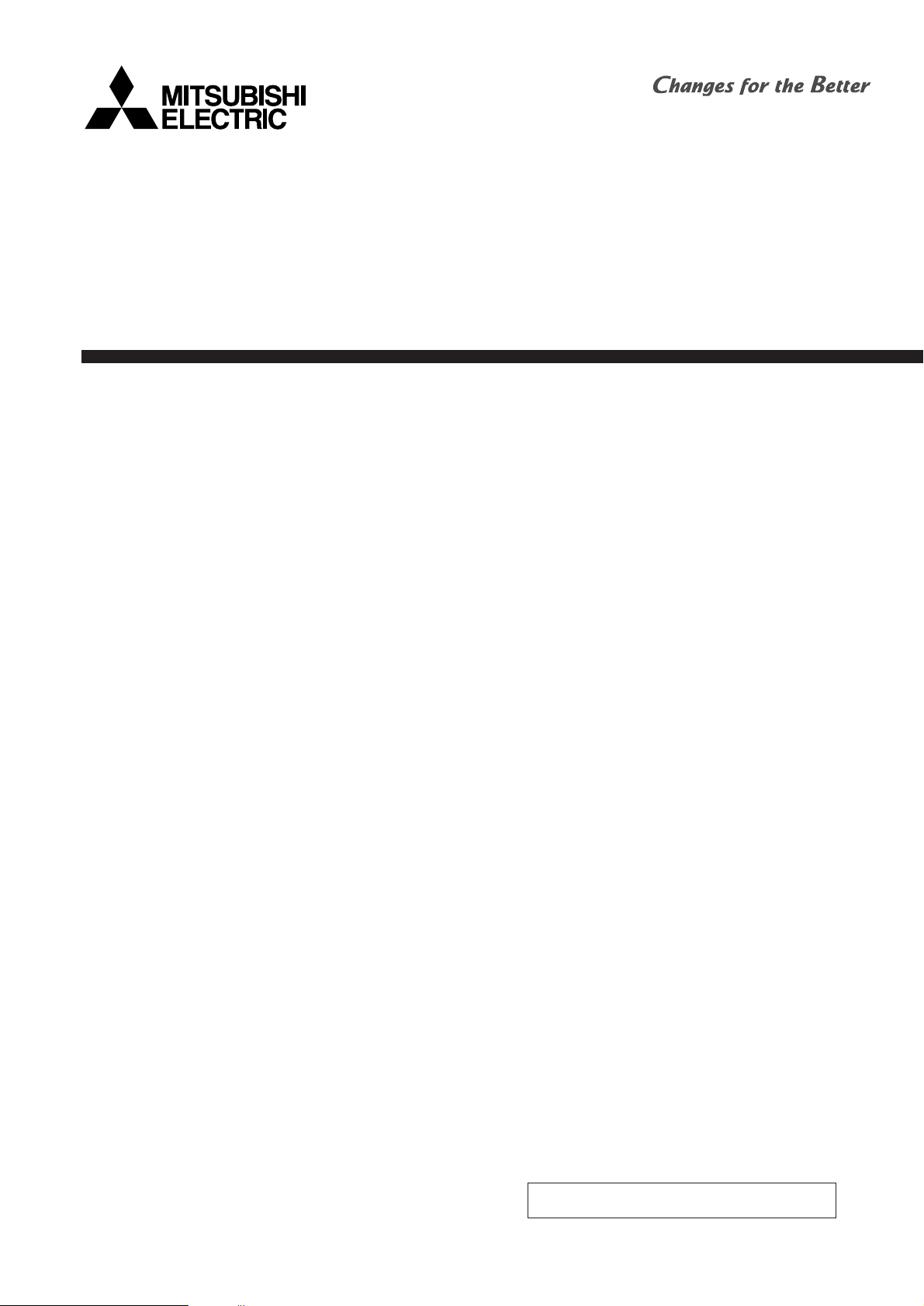
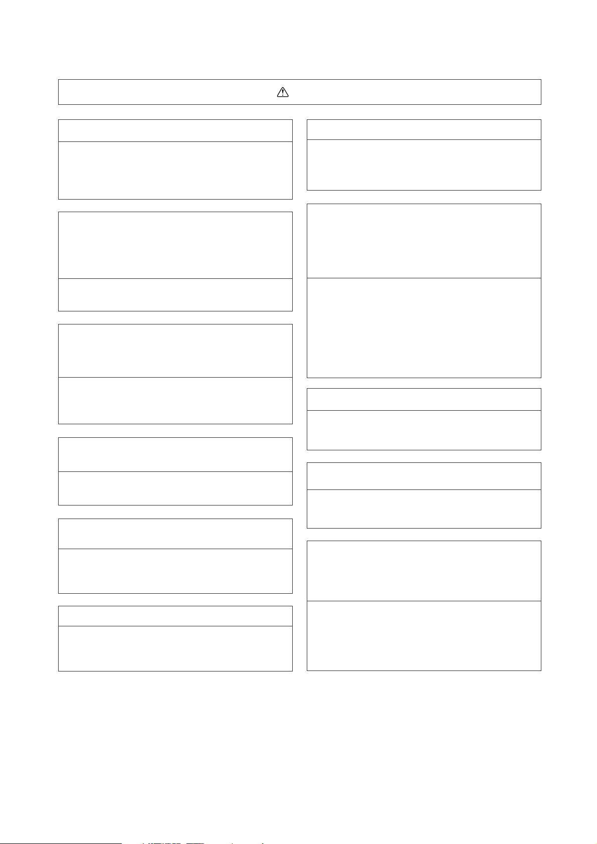
[1] Storage of Piping Material
(1) Storage location
Store the pipes to be used indoors. (Warehouse at site or owner’s warehouse)
Storing them outdoors may cause dirt, waste, or water to infiltrate.
(2) Pipe sealing before storage
Both ends of the pipes should be sealed until immediately before brazing.
Wrap elbows and T’s in plastic bags for storage.
* The new refrigerator oil is 10 times more hygroscopic than the conventional refrigerator oil (such as Suniso). Water
infiltration in the refrigerant circuit may deteriorate the oil or cause a compressor failure. Piping materials must be stored
with more care than with the conventional refrigerant pipes.
OK
OK
NO
NO
Page 5
- 3 -
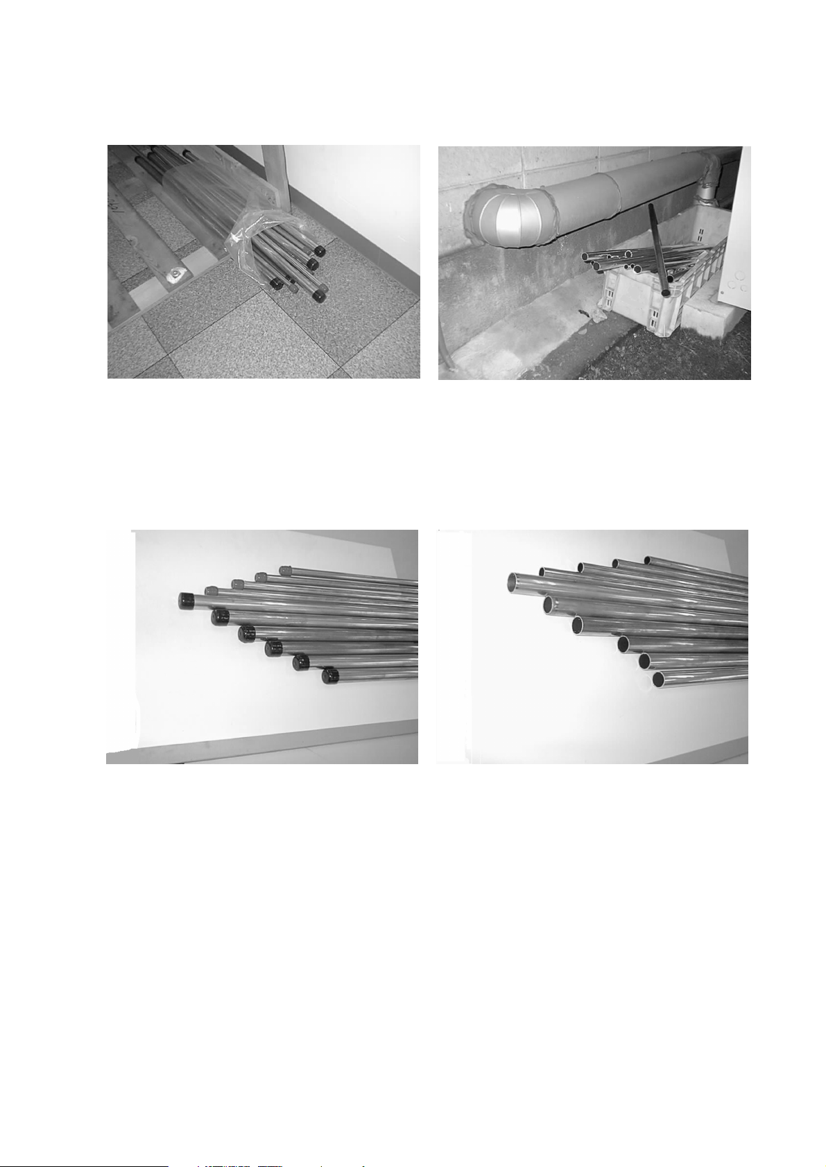
[2] Piping Machining
Use ester oil, ether oil or alkylbenzene (small amount) as the refrigerator oil to coat flares and flange connections.
Use only the necessary minimum quantity of oil.
Reason:
1. The refrigerator oil used for the equipment is highly hygroscopic and may introduce water inside.
Notes:
• Introducing a great quantity of mineral oil into the refrigerant circuit may also cause a compressor failure.
•
Do not use oils other than ester oil, ether oil or alkylbenzene.
Page 6
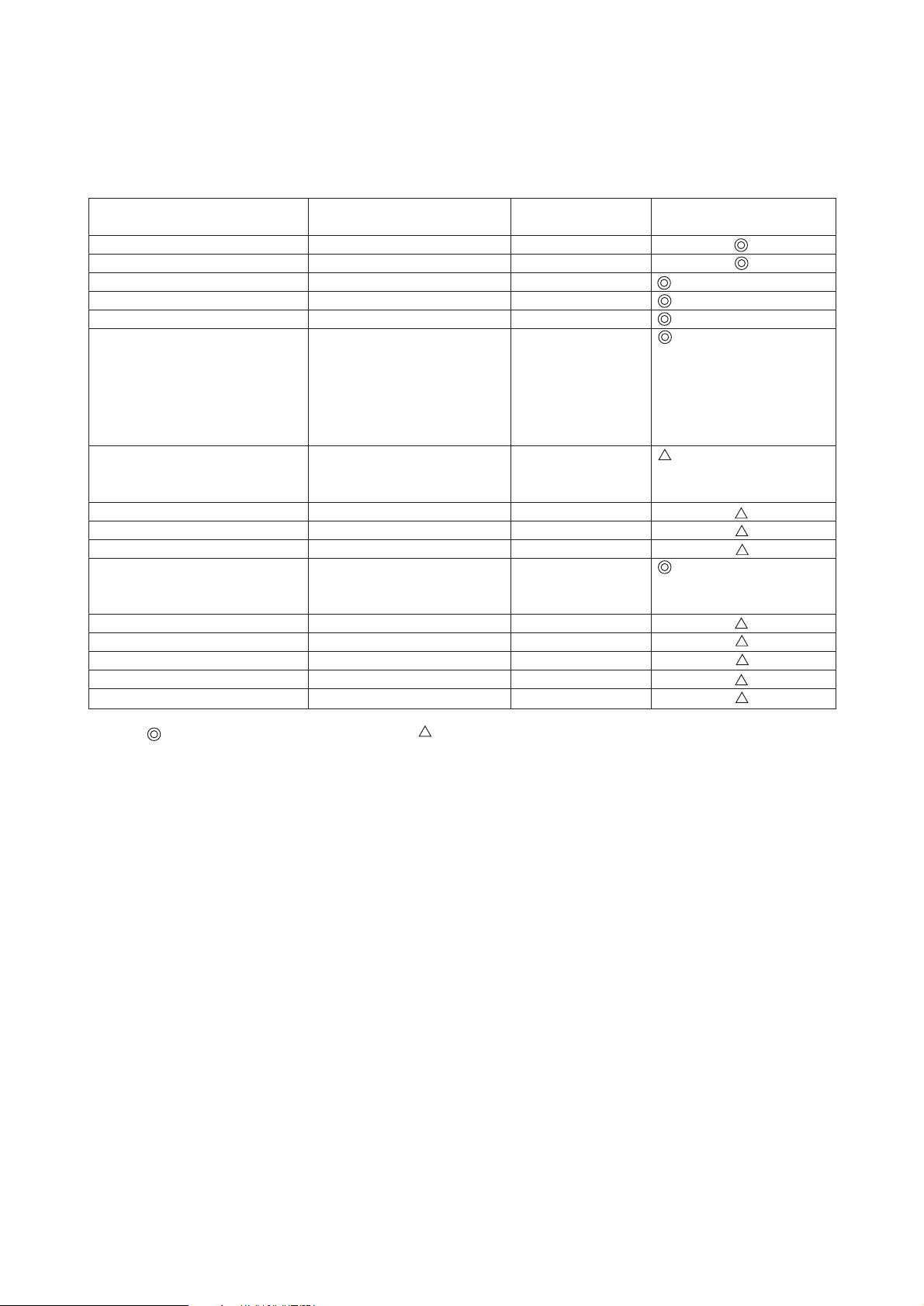
[3] Necessary Apparatus and Materials and Notes on Their Handling
The following tools should be marked as dedicated tools for R407C.
<<Comparison of apparatus and materials used for R407C and for R22>>
Apparatus Used Use R22 R407C
Gauge manifold Evacuating, refrigerant filling Current product
Charging hose Operation check Current product
Charging cylinder Refrigerant charging Current product Do not use
Gas leakage detector Gas leakage check Current product Shared with R134a
Refrigerant collector Refrigerant collection R22 For R407C use only
Refrigerant cylinder Refrigerant filling R22 Identification of dedi-
cated use for R407C:
Record refrigerant
name and put brown
belt on upper part of
cylinder.
Vacuum pump Vacuum drying Current product Can be used by attach-
ing an adapter with a
check valve.
Vacuum pump with a check valve Current product
Flare tool Flaring of pipes Current product
Bender Bending of pipes Current product
Application oil Applied to flared parts Current product Ester oil or Ether oil or
Alkybenzene (Small
amount)
Torque wrench Tightening of flare nuts Current product
Pipe cutter Cutting of pipes Current product
Welder and nitrogen cylinder Welding of pipes Current product
Refrigerant charging meter Refrigerant charging Current product
Vacuum gauge Checking the vacuum degree Current product
Symbols: To be used for R407C only. Can also be used for conventional refrigerants.
Tools for R407C must be handled with more care than those for conventional refrigerants. They must not come into contact
with any water or dirt.
- 4 -
Page 7
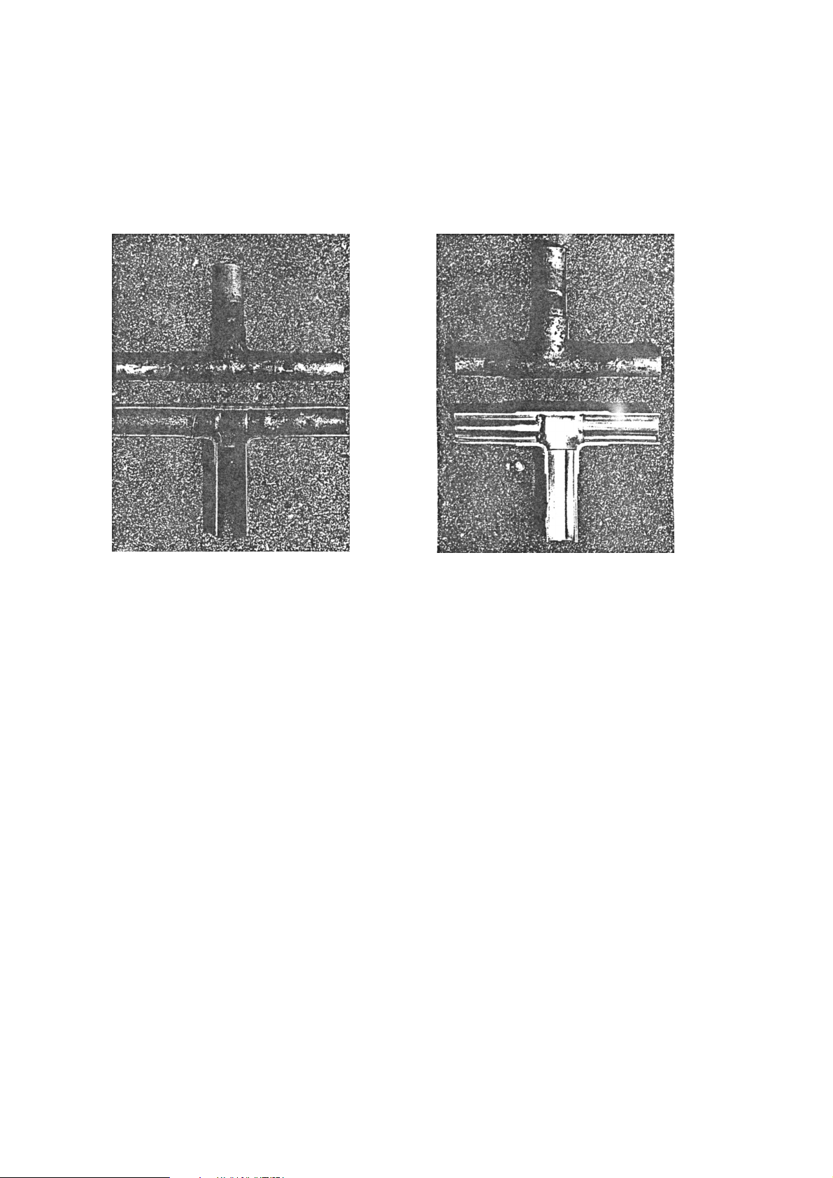
[4] Brazing
No changes from the conventional method, but special care is required so that foreign matter (ie. oxide scale, water, dirt,
etc.) does not enter the refrigerant circuit.
Example: Inner state of brazed section
When non-oxide brazing was not used When non-oxide brazing was used
Items to be strictly observed:
1. Do not conduct refrigerant piping work outdoors on a rainy day.
2. Apply non-oxide brazing.
3. Use a brazing material (BCuP-3) which requires no flux when brazing between copper pipes or between a copper
pipe and copper coupling.
4. If installed refrigerant pipes are not immediately connected to the equipment, then braze and seal both ends of them.
Reasons:
1. The new refrigerant oil is 10 times more hygroscopic than the conventional oil. The probability of a machine failure if
water infiltrates is higher than with conventional refrigerant oil.
2. A flux generally contains chlorine. A residual flux in the refrigerant circuit may generate sludge.
Note:
• Commercially available antioxidants may have adverse effects on the equipment due to its residue, etc. When
applying non-oxide brazing, use nitrogen.
- 5 -
Page 8
[5] Airtightness Test
No changes from the conventional method. Note that a refrigerant leakage detector for R22 cannot detect R407C leakage.
Halide torch R22 leakage detector
Items to be strictly observed:
1. Pressurize the equipment with nitrogen up to the design pressure and then judge the equipment’s airtightness, taking
temperature variations into account.
2. When investigating leakage locations using a refrigerant, be sure to use R407C.
3. Ensure that R407C is in a liquid state when charging.
Reasons:
1. Use of oxygen as the pressurized gas may cause an explosion.
2. Charging with R407C gas will lead the composition of the remaining refrigerant in the cylinder to change and this
refrigerant can then not be used.
Note:
•A leakage detector for R407C is sold commercially and it should be purchased.
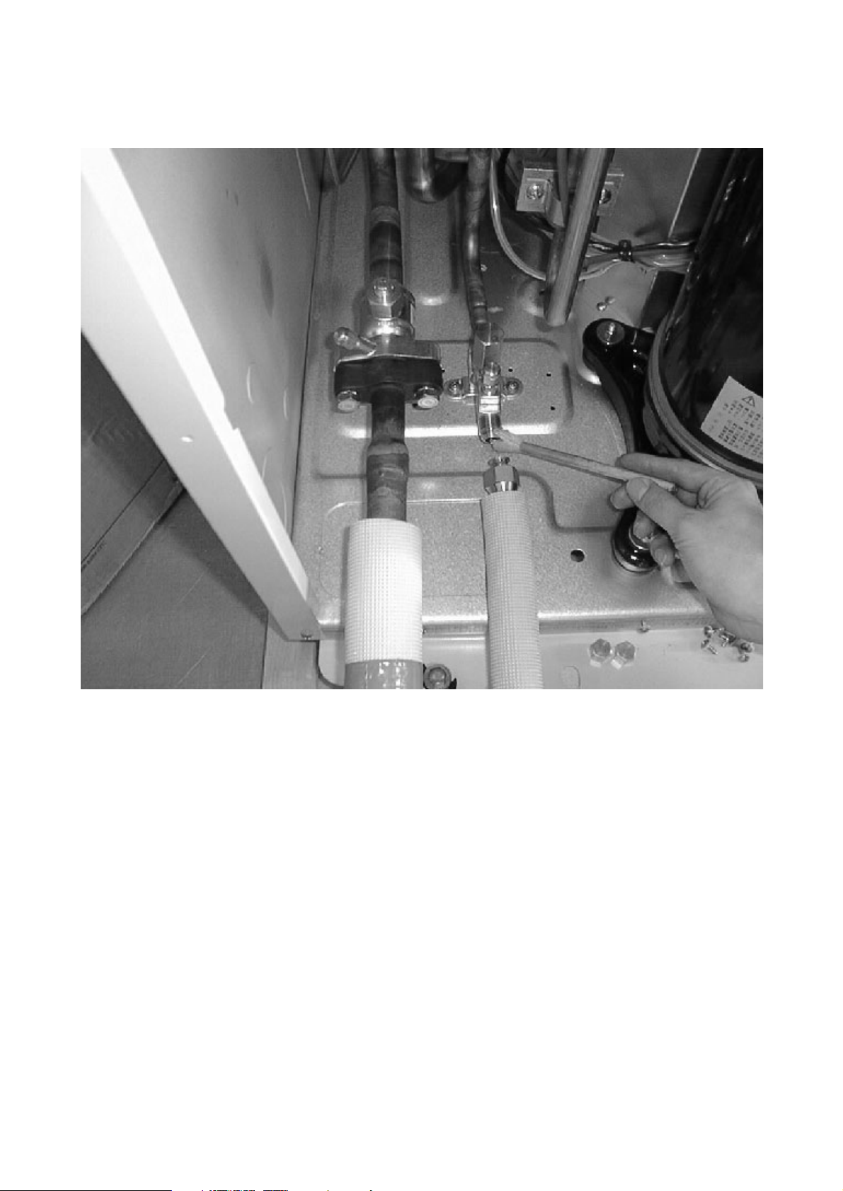
[6] Vacuuming
1. Vacuum pump with check valve
A vacuum pump with a check valve is required to prevent the vacuum pump oil from flowing back into the refrigerant
circuit when the vacuum pump power is turned off (power failure).
It is also possible to attach a check valve to the actual vacuum pump afterwards.
2. Standard degree of vacuum for the vacuum pump
Use a pump which reaches 0.5 Torr (500 MICRON) or below after 5 minutes of operation.
In addition, be sure to use a vacuum pump that has been properly maintained and oiled using the specified oil. If the
vacuum pump is not properly maintained, the degree of vacuum may be too low.
3. Required accuracy of the vacuum gauge
Use a vacuum gauge that can measure up to 5 Torr. Do not use a general gauge manifold since it cannot measure a
vacuum of 5 Torr.
4. Evacuating time
•Evacuate the equipment for 1 hour after -755 mmHg (5 Torr) has been reached.
• After envacuating, leave the equipment for 1 hour and make sure the that vacuum is not lost.
5. Operating procedure when the vacuum pump is stopped
In order to prevent a backflow of the vacuum pump oil, open the relief valve on the vacuum pump side or loosen the
charge hose to drawn in air before stopping operation.
The same operating procedure should be used when using a vacuum pump with a check valve.
NO
NO
- 6 -
Page 9
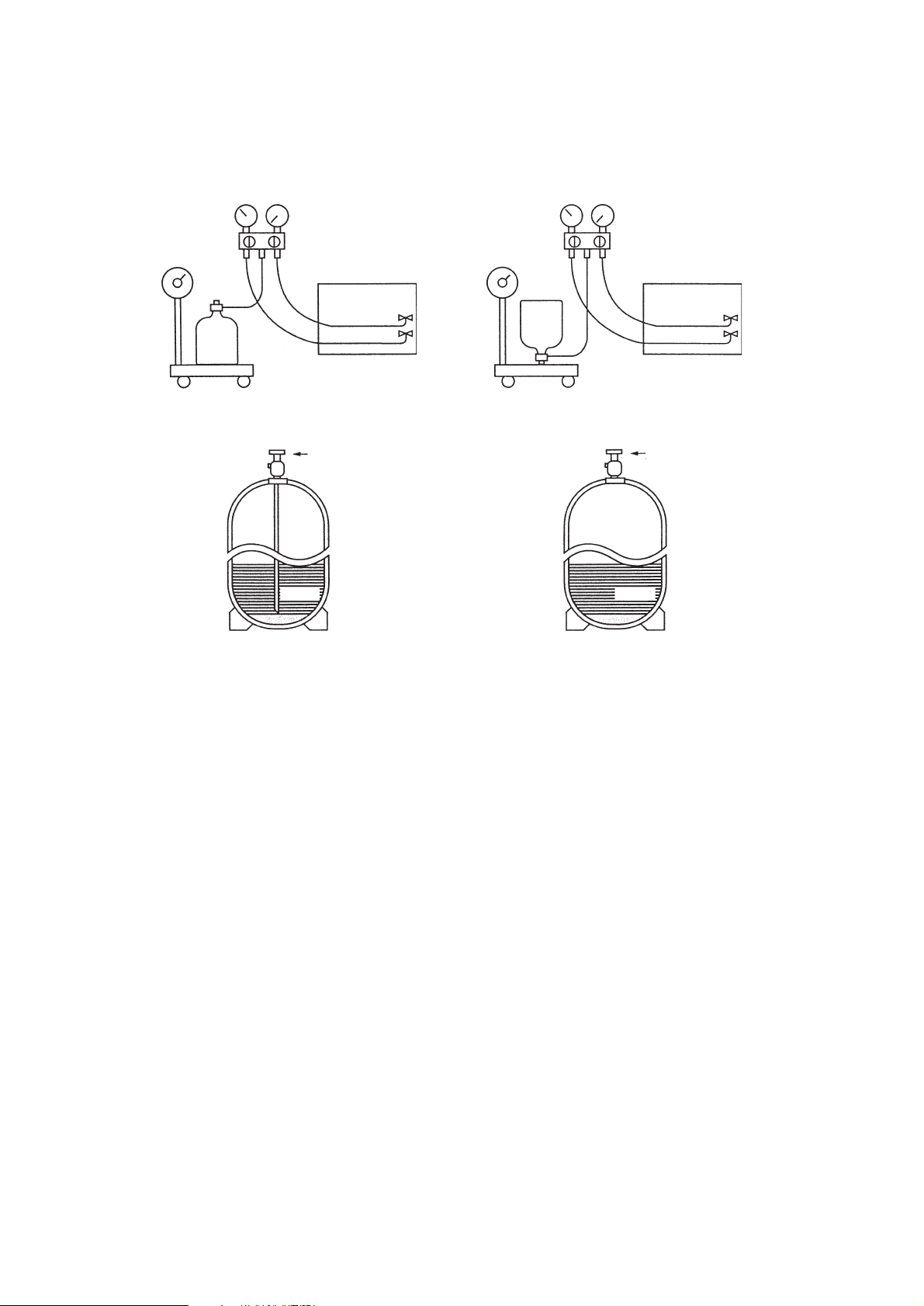
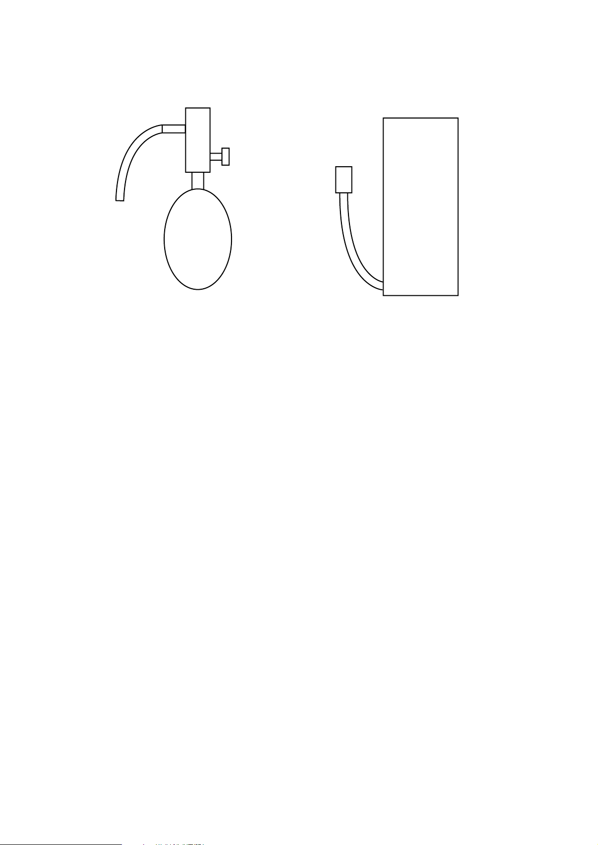
[7] Charging of Refrigerant
R407C must be in a liquid state when charging, because it is a non-azeotropic refrigerant.
For a cylinder with a syphon attached For a cylinder without a syphon attached
Cylinder color identification R407C-Gray Charged with liquid refrigerant
R410A-Pink
Reasons:
1. R407C is a mixture of 3 refrigerants, each with a different evaporation temperature. Therefore, if the equipment is
charged with R407C gas, then the refrigerant whose evaporation temperature is closest to the outside temperature is
charged first while the rest of refrigerants remain in the cylinder.
Note:
• In the case of a cylinder with a syphon, liquid R407C is charged without turning the cylinder up side down. Check the
type of cylinder before charging.
Cylin-
der
Cylin-
der
Valve
Valve
Liquid
Liquid
- 7 -
Page 10
Air inlet
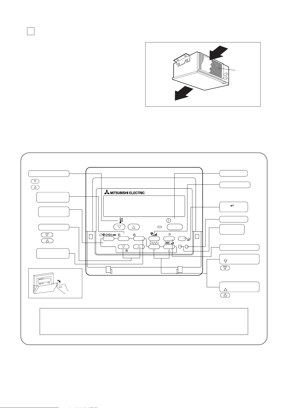
2 PART NAMES AND FUNCTIONS
Indoor unit
• Air inlet : Sucks the ambient air in.
• Filter : The filter bruit into the unit as standard is a
simple filter to remove visible dust and dirt. If
air pulification is one of the conditions required
for use, consult with your dealer.
• Air outlet : Blows the air back out into the room.
Remote controller (PAR-21MAA)
• Once the controls are set, the same operation mode can be repeated by simply pressing the ON/OFF button.
Operation buttons
- 8 -
PAR-21MAA
ON/OFF
FILTER
CHECK
OPERATION
CLEAR
TEST
TEMP.
MENU
BACK DAY
MONITOR/SET
CLOCK
ON/OFF
Set Temperature buttons
Down
Up
Timer Menu button
(Monitor/Set button)
Mode button
(Return button)
Set Time buttons
Back
Ahead
Timer On/Off button
(Set Day button)
Opening the
door.
ON/OFF button
Fan Speed button
Filter button
(<Enter> button)
Test Run button
Airflow Up/Down button
Louver button
(
Operation button)
To preceding
operation number.
Ventilation button
(
Operation button)
To next operation
number.
Note:
If you press a button for a feature that is not installed at the indoor unit, the remote controller will display the “Not Available”
message.
If you are using the remote controller to drive multiple indoor units, this message will appear only if the feature is not present
at the parent unit.
Check button
(Clear button)
Air outlet
Filter
Page 11

Display
- 9 -
Caution
● Only the (Power on indicator) lights when the unit is stopped and power supplied to the unit.
● When the central control remote control unit, which is sold separately, is used the ON-OFF button, operation switch button
and TEMP. adjustment button do not operate.
● If you press a button for a feature that is not installed at the indoor unit, the remote controller will display the “Not Available”
message.
● When power is turned ON for the first time, it is normal that “PLEASE WAIT” is displayed on the screen (For max. 3minutes).
Please wait until this “PLEASE WAIT” disappear then start the operation.
For purposes of this explanation,
all parts of the display are shown
as lit. During actual operation, only
the relevant items will be lit.
˚F˚C
˚F˚C
ERROR CODE
AFTER
TIMER
TIME SUN MON TUE WED THU FRI SAT
ON
OFF
Hr
AFTER
FILTER
FUNCTION
ONLY1Hr.
WEEKLY
SIMPLE
AUTO OFF
Identifies the current operation
Shows the operating mode, etc.
* Multilanguage display is sup-
ported.
“Centrally Controlled” indicator
Indicates that operation of the remote controller has been prohibited by a master controller.
“Timer Is Off” indicator
Indicates that the timer is off.
Temperature Setting
Shows the target temperature.
Day-of-Week
Shows the current day of the week.
Time/Timer Display
Shows the current time, unless the simple or Auto Off
timer is set.
If the simple or Auto Off timer is set, shows the time
remaining.
“Sensor” indication
Displayed when the remote controller
sensor is used.
“Locked” indicator
Indicates that remote controller buttons have been locked.
“Clean The Filter” indicator
Comes on when it is time to clean the
filter.
Timer indicators
The indicator comes on if the corresponding timer is set.
Up/Down Air Direction indicator
The indicator shows the direction of the outcoming airflow.
“One Hour Only” indicator
Displayed if the airflow is set to
weak and downward during COOL
or DRY mode. (Operation varies
according to model.)
The indicator goes off after one
hour, at which time the airflow direction also changes.
Room Temperature display
Shows the room temperature.
Louver display
Indicates the action of the swing
louver. Does not appear if the
louver is stationary.
(Power On indicator)
Indicates that the power is on.
Fan Speed indicator
Shows the selected fan speed.
Ventilation indicator
Appears when the unit is running in
Ventilation mode.
Page 12

3 SPECIFICATIONS
Specifications of air-source heat pump type packaged air conditioner
(Ceiling concealed type indoor unit)
Model name PEH-P400MYA Quantity Symbol
Capacity kcal/h
kW
Indoor side Dry bulb temperature/wet bulb temperature
Outdoor side Dry bulb temperature/wet bulb temperature
Power source
Power consumption kW
Operating current A
Remote controller temperature setting range °C
Airflow direction control
Type × Quantity
Airflow rate m3/min
External static pressure Pa
Motor output kW
External finish
Unit (H × W × D) mm
Panel (H × W × D) mm
Heat exchanger type
Air filter
Insulation material
Refrigerant piping dimension Liquid/Gas
φ
mm
Drain piping dimension
φ
mm
Noise level dB (A)
Net
Control capacity
weight kg
%
Minimum wire thickness
Circuit breaker
Operation control device (provided)
Decoration panel (Option)
Other mountable major options
Accessories
Special note, Non-standard specifications, etc.
1. The cooling and heating capacities are the maximum capacities that were obtained by operating in the above
air conditions and with a refrigerant pipe of about 7.5 m.
2. The actual capacity characteristics vary with the combination of indoor and outdoor units. See the technical
informaition.
3. The operating noise is the data that was obtained by measuring it 1.5 m from the unit’s bottom in an anechoic
room. (Noise meter A-scale value)
Cooling Heating
36,000 40,800
41.8 47.4
27 °C/19 °C 20 °C/–
35 °C/24 °C7 °C/6 ˚C
3N~ 380/415V 50Hz
2.3/2.3/2.3 2.3/2.3/2.3
4.5/4.3/4.1 4.5/4.3/4.1
19 ~ 30 17 ~ 28
–
Sirrocco fan × 2
140
150, 170, 180
1.5
Galvanizing
706 × 1,690 × 865
–
Cross fin
Saran net
Polyethylene foam
(12.7/25.4) × 2
25.4 (R1)
54, 55, 55
180
0 - 50 -100
1.6 mm
15 A
Remote controller: PAR-21MAA
–
–
Electrical characteristics
Fan
External dimension
External wiring
Composing parts
Notes:
Installation manual, Operation manual,
Remote controller
–
Air con-
dition
- 10 -
Page 13

Specifications of air-source heat pump type packaged air conditioner
(Ceiling concealed type indoor unit)
Model name
PEH-P500MYA
Quantity Symbol
Capacity kcal/h
kW
Indoor side Dry bulb temperature/wet bulb temperature
Outdoor side Dry bulb temperature/wet bulb temperature
Power source
Power consumption kW
Operating current A
Remote controller temperature setting range °C
Airflow direction control Vertical
Type × Quantity
Airflow rate m3/min
External static pressure Pa
Motor output kW
External finish
Unit (H × W × D) mm
Panel (H × W × D) mm
Heat exchanger type
Air filter
Insulation material
Refrigerant piping size Liquid/Gas
φ
mm
Drain piping size
φ
mm
Noise level dB (A)
Net
Control capacity
weight kg
%
Minimum wire thickness
Circuit breaker
Operation control device (provided)
Decoration panel (Option)
Other mountable major options
Accessories
Special note, Non-standard specifications, etc.
1. The cooling and heating capacities are the maximum capacities that were obtained by operating in the above
air conditions and with a refrigerant pipe of about 7.5 m.
2. The actual capacity characteristics vary with the combination of indoor and outdoor units. See the technical
informaition.
3. The operating noise is the data that was obtained by measuring it 1.5 m from the unit’s bottom in an anechoic
room. (Noise meter A-scale value)
Cooling Heating
44,800 52,400
52.0 61.0
27 °C/19 °C 20 °C/–
35 °C/24 °C7 °C/ 6 °C
3N~ 380/415V 50 Hz
2.5/2.5/2.5 2.5/2.5/2.5
5.1/4.9/4.7 5.1/4.9/4.7
19 ~ 30 17 ~ 28
–
Sirrocco fan × 2
170
150, 160, 180
2.0
Galvanizing
706 × 1,993 × 865
–
Cross fin
Saran net
Polyethyene foam
(12.7/28.58) × 2
25.4 (R1)
60, 60, 60
212
0 - 50 - 100
1.6 mm
15 A
Remote controller: PAR-21MAA
–
–
Electrical characteristics
Fan
External dimension
External wiring
Composing parts
Notes:
Installation manual, Operation manual,
Remote controller
–
Air con-
dition
- 11 -
Page 14

4 PART NAMES AND FUNCTIONS
(1) Indoor Unit
• Models PEH-P400MYA
(1)
When connecting air inlet
(2)
When installing the suspension fixtures prior to installation of the
indoor unit without inlet duct
(3)
When hanging the indoor unit directly without inlet duct
(A)
Service space
(B)
Suspension bolt pitch
(C)
Air inlet
(D)
Air outlet
400
1587
1637
2187
200
200
746700
620
63
946
706
500
1206
25
75
*1
*1 When there is not 500mm of service space on top of the unit, there must be 700mm
of service space at the air outlet side.
(1)
(3)
(A)
(A)
(C)
(B)
(B)
(D)
(2)
Return air
sensor
Refrigerant pipe
ø25.4(1 braze)
Refrigerant pipe
ø12.7(1/2 braze)
Refrigerant pipe
ø12.7(1/2 braze)
Refrigerant pipe
ø25.4(1 braze)
Right side view
Left side view
Front view
Top view
Rubber bush <For the
controller wiring>
(Bottom side)
Rubber bush <For the
outdoor unit connecting
wiring> (Bottom side)
Rubber bush <For the
power supply wiring>
(Bottom side)
Return air
Supply air
A
View A
(2 Places)
81
150 1388 49
10X130Pitch=1300
280 1099 208
865
51
15
15
50158750
917425674211
24
4-ø12 Holes
Return air
duct flange
34-
ø3 Holes
26-
ø3 Holes
Control box
Supply air
duct flange
Drain R1
110
5X110Pitch=550
3X130Pitch=390
160
207
1637 2525
130
29.5
8X130Pitch=1040
42
60606040
1690
425
29.5
15
15
44
620
130
6363
44
50
130
600
100
87
36
462207
36
706
69
37
19
745
2327
<For hanging bolt M10>
[Field supply]
- 12 -
Page 15

• Models PEH-P500MYA
(1)
When connecting air inlet
(1)
(2)
(3)
(2)
When installing the suspension fixtures prior to installation of the
indoor unit without inlet duct
(3)
When hanging the indoor unit directly without inlet duct
(A)
Service space
(A)
(A)
(B)
(B)
(C)
(D)
(B)
Suspension bolt pitch
(C)
Air inlet
(D)
Air outlet
400
1890
1940
2490
200
200
746700
620
63
946
706
500
1206
25
75
*1
*1 When there is not 500mm of service space on top of the unit, there must be 700mm
of service space at the air outlet side.
Return air
sensor
Refrigerant pipe
ø12.7(1/2 braze)
Refrigerant pipe
ø28.58(1-1/8 braze)
Refrigerant pipe
ø28.58(1-1/8 braze)
Refrigerant pipe
ø12.7(1/2 braze)
View A
A
Right side view
Left side view
Front view
Return air
Supply air
Top view
Rubber bush <For the
controller wiring>
(Bottom side)
Rubber bush <For t he
outdoor unit connecting
wiring> (Bottom side)
Rubber bush <For the
power supply wiring>
(Bottom side)
91
54
(2 Places)
130
100
110
50
25
1890
1099
90
60
190
29.5
15
15
5X110Pitch=550
44
620 6363
40
44
29.5
25
24
130
600
323
51
87
36
193
462207
36
706
69
37
19
745
23
1993
8X130Pitch=1040
425
1940
60
85
130
160
1648
4-ø12 Holes
27
3X130Pitch=390
207
60
Return air
duct flange
50
38-ø3 Holes
Control box
90
12X130Pitch=1560
15
865
15
42 49
251
468
26-ø3 Holes
Drain R1
Supply air
duct flange
<For hanging bolt M10>
[Field supply]
81
- 13 -
Page 16

(2) Remote Controller
• Models
PAR-21MAA
- 14 -
120
(Front view) (Side view) (Rear view)
130
19
83.5
46
Page 17

5 ELECTRICAL WIRING DIAGRAM
(1) Indoor Unit
• Models PEH-P400,500MYA
SUPPLY AIR
DUCT
RETURN AIR
DUCT
7. mark is connector.
Caution,
1.To protect fan motor from abnormal
current, over current relays is installed.
Therefore, do not change factory set
value of over current relays.
PEH-P400,500MYA : 15A
CIRCUIT BREAKER
(FIELD SUPPLY)
3N~PE
380/400/415V
50HZ
POWER SUPPLY
TO OUTDOOR UNIT
CONNECTING WIRES
(POLAR)
TO OUTDOOR UNIT
CONNECTING WIRES
(POLAR)
(No.2)
CONTROLLER BOARD
INDOOR
Note:
1.The dotted lines show field wiring.
2.Color of earth wire is yellow and green
twisting.
3.Specification subject to change without
notice.
(No.2)
(No.1)
POWER BOARD
INDOOR
INDOOR
POWER BOARD
BOARD
REMOTE CONTROLLER
(No.1)
CONTROLLER BOARD
INDOOR
SYMBOL NAME
AUXILIARY RELAYX1,2
TB6
SYMBOL
TB3
SYMBOL
NAME
NAME
INDOOR
CONTROLLER
BOARD
FB21,FB22
6.SW2(*1) shows PEH-P500MYA setting.
(2 places)
In case of PEH-P400MYA setting is
shown as below.
FB11,FB12 FERRITE CORE
TERMINAL BLOCK
TERMINAL BLOCK
COND/EVA TEMP
LIQUID PIPE TEMP
ROOM TEMP
OUTDOOR UNIT
52F MAGNETIC CONTACTOR (INDOOR FAN MOTOR)
SURGE KILLERCR
SWITCH(EMERGENCY OPERATION)
SWITCH(CAPACITY CORD)
SW1 SWITCH(MODEL SELECTION)
TH5-1,5-2
4.Indoor and outdoor connecting wires
are made with polarities, make sure
matching wiring and terminal.
5.Emergency operation
If a trouble occurs with either the remote
controller or the indoor microcomputer
and no other trouble exists, emergency
controller board.
switch (SWE) "ON" on the indoor
operation for cooling or heating can be
performed by changing the setting of
LED (TRANSMISSION<INDOOR.OUTDOOR>)LED3
LED (POWER SUPPLY<REMOTE CONTROLLER>)LED2
LED (POWER SUPPLY)LED1
SWE
SW2
VARISTORZNR
FUSE (T6.3AL250V)FUSE
REMOTE CONTROLLER
INDOOR UNIT
THERMISTOR
TERMINAL BLOCK
INTERNAL THERMOSTAT (INDOOR FAN MOTOR)
OVER CURRENT RELAY (INDOOR FAN MOTOR)
FAN MOTOR (INDOOR)
TH2-1,2-2
TH1-1,1-2
TB2,4-1,4-2,5
49F
51F
MF1
X4-6 AUXILIARY RELAY
X6X5X4
X6X5X4
CR
4123
(*1)SW2
OFF
ON
5
51F
51F
FB22
FB12
5
C01
49F
3
2
1
C01
TB4-1
TB4-2
TH1-2
TH2-2
TH5-2
TH5-1
TH2-1
TH1-1
OUTDOOR UNIT
X2
S3
S2
S1
FB21
RED
BLUE
X2
X1
X1
52F
L1
L2
L3
N
LCD
TB2
MF1
TB6
TB5
S3
S2
REMOTE CONTROLLER
INDOOR UNIT CONTROL BOX
OUTDOOR UNIT
(No. 2)
(No. 1)
2
1
4
PE
S1
52F
RED
WHITE
BLACK
PE
PE
PE
PE
PE
FB11
1
2
2
1
2
1
4
3
2
1
CN29
CN41
CN21
CN20
ON
OFF
SWE
ON
OFF
SW1
54321
CN3C
2
1
3
7
8
9
4
5
6
3
3
1
2
1
2
1
2
1
2
LED3
LED2
LED1
X6X5X4
375 1
DC13.1V
2 113
13
13
ZNR
FUSE
54321
CN51
CN31
CN32
CND
CNDK
FAN
CN2L
CN22
CN90
CN2D
DC
13.1V
CN2S
1
2
CNSK
1
3
DC
13.1V
CN2S
1
2
CNSK
1
3
CN3C
2
1
3
7
8
9
4
5
6
3
3
1
2
1
2
1
2
1
2
LED3
LED2
LED1
DC13.1V
21 13
13
ZNR
FUSE
54321
CN51
CN31
CN32
CND
CN2L
CN22
CN90
CN2D
1
2
2
1
2
1
4
3
2
1
CN29
CN41
CN21
CN20
ON
OFF
SWE
ON
OFF
SW1
54321
X6X5X4
375 1
13
CNDK
FAN
TAB1
TAB1
5
ON
OFF
(*1)SW2
3214
5
ON
OFF
(*1)SW2
3214
PE
N
L1
T B 1
T B 3
L2
L3
S1
S2
S3
PE
N
L1
T B 1
T B 3
L2
L3
S1
S2
S3
POWER
3N~
380/400/415V
POWER
3N~
380/400/415V
- 15 -
Page 18

- 16 -
0
0.05
0.1
0.15
0.2
0.25
130123 140 150 160 168
0
0.05
0.1
0.15
0.2
0.25
150143 160 170 180 190 200 204
6 TECHNICAL DATA TO MEET LVD
[1] Capacity/Input Ratio against Changes in Room Airflow Rate
Heating
130123 140 150 160 168
Capacity/Input ratio
Airflow rate (m3/min)
1.0
1.05
0.95
Cooling
Input
Capacity
123 140130 150 160 168
Capacity/Input ratio
Airflow rate (m3/min)
1.0
1.05
1.08
0.95
Input
Capacity
Heating
143 160150 170 180 190 200 204
Capacity/Input ratio
Airflow rate (m3/min)
1.0
1.05
1.08
0.95
Input
Capacity
150143 160 170 180 190 200 204
Capacity/Input ratio
Airflow rate (m3/min)
1.0
1.05
0.95
Cooling
Input
Capacity
• Models PEH-P400MYA
• Models
PEH-P500MYA
[2] Bypass Factor Curves
Bypass factor
Airflow rate (m3/min)
Bypass factor
Airflow rate (m3/min)
PEH-P500MYA
PEH-P400MYA
Page 19

- 17 -
[3] Cooling Sensible Heating Capacity Table
(1) PEH-P400MYA (Airflow rate 140m3/min)
(2) PEH-P500MYA (Airflow rate 170m
3
/min)
Outdoor
temp.
(°C)
20
25
30
35
40
43
Indoor inlet air temperature (DB/WB°
C)
CA SHC CA SHC
CA
SHC CA SHC CA SHC
23/16 25/18 27/19 28/20 30/22
Outdoor
temp.
(°C)
20
25
30
35
40
43
Indoor inlet air temperature (DB/WB°
C)
CA SHC CA SHC
CA
SHC CA SHC CA SHC
23/16 25/18 27/19 28/20 30/22
External static pressure (Pa)
Operating airflow range
Airflow rate (m
3
/min)
External static pressure (Pa)
Operating airflow range
Airflow rate (m
3
/min)
PEH-P400MYA
PEH-P500MYA
[4] Airflow Characteristic Curves
36200 29200 38600 28900
40000 31000 41600 30900
43800 30400
35000 28600 37400 28400
39000 30500 40600 30500
43000 30100
33800 28100 36200 27900
37800 30100 39400 30100
41800 29700
32400 27400 34800 27300
36000 29300 38000 29500 40400 29200
30600 26600 33200 26700
34800 28800 36400 28900 39000 28700
29600 26200 32000 26200
33800 28400 35400 28500 38000 28300
45000 32900 48000 32700 49800 34600 51600 34600 54600 34100
43600 32200 46600 32000 48600 34100 50400 34100 53400 33600
42000 31400 45000 31300 47000 33400 49000 33500 52000 33000
40200 30600 43200 30500 44800 32500 47200 32700 50400 32400
38200 29600 41200 29600 43200 31800 45400 32000 48400 31600
36800 29000 40000 29100 42000 31300 44000 31400 47200 31200
0
50
100
150
200
250
120 130 140 150 160 170
0
50
100
150
200
250
140 150 160 170 180 190 210200
Page 20

- 18 -
[5] Center of Gravity (Indoor unit)
• Models PEH-P400MYA/P500MYA
Item
Model name
PEH-P400MYA 830
1015
420
390
340
340
PEH-P500MYA
Center of gravity
XYZ
unit : (mm)
Y
Z
X
Page 21

- 19 -
[6] NC Curve (Indoor unit)
1m 2m
1.5m
Measured point
Aux. duct
1m 2m
1.5m
Measured point
Aux. duct
PEH-P400MYA
Measurement condition
PEH-P500MYA
Measurement condition
OCTAVE BAND CENTER FREQUENCIES <Hz>
OCTAVE BAND PRESSURE LEVEL <dB> 0dB = 20
µPa
OCTAVE BAND CENTER FREQUENCIES <Hz>
OCTAVE BAND PRESSURE
LEVEL
<dB>
0dB = 20
µPa
External static pressure: 150Pa
Approximate minimum
audible limit on
continuous noise
Approximate minimum
audible limit on
continuous noise
10
20
30
40
50
60
70
80
90
63Hz 125Hz 250Hz 500Hz 1000Hz 2000Hz 4000Hz 8000Hz
NC-40
NC-30
NC-20
NC-70
NC-60
NC-50
10
20
30
40
50
60
70
80
90
63Hz 125Hz 250Hz 500Hz 1000Hz 2000Hz 4000Hz 8000Hz
NC-20
NC-30
NC-40
NC-50
NC-60
NC-70
External static pressure: 150Pa
Page 22

- 20 -
7 SERVICE DATA
[1] Appearance of Equipment
• PEH-P400MYA/P500MYA Electrical Parts Box (with cover removed)
Over current
relay
(fan motor)
Terminal bed
(remote controller
transmission line)
Magnetic
contactor
(fan motor)
Terminal bed TB4-2(No.2)Terminal bed (power)
(indoor/outdoor connecting line)
Terminal bed TB4-1(No.1)
Auxiliary relay
(indoor/outdoor connecting line)
Indoor power board (No.1)
Indoor power board (No.2) Indoor circuit board (No.1)
Indoor circuit board
(No.2)
Page 23

- 21 -
[2] Internal Construction
• PEH-P400MYA/P500MYA (Indoor unit)
Refrigerant piping connection (No.2) : øB
Refrigerant piping connection (No.2) : øA
Refrigerant piping connection (No.1) : øB
Refrigerant piping connection (No.1) : øA
Leg
(for installation)
Air filter
Heat exchanger
Fan motor
Sirrocco fan
Drian connection (R1)
Electrical parts box
Drain pan
Model name
PEH-P400MYA
PEH-P500MYA
A
25.4
28.58
B
12.7
12.7
[3] Refrigerant Circuit
Brazing connection
Indoor Heat exchanger
Cooling operation
PEH-P400, 500MYA is comprised of two refrigerant cycles.
Heating operation
Page 24

- 22 -
8 FUNCTION OF SWITCH ON INDOOR CIRCUIT BOARD
[1] DIP SW1 for model Selection (DIP SW1 has been set at factory)
[2] DIP SW2 for Capacity Setting (DIP SW2 has been set at factory)
[3] DIP SWE for Emergency Operation
When SWE is turned ON, FAN turns ON. Setting of emergency operation other than SWE is
performed at the outdoor unit. For a description of the specific emergency operation execution
method, refer to the outdoor unit (PUH-P200MYA, PUH-P250MYA) Technical & Service Manual.
PEH-P400MYA/P500MYA : SW1-1, -4 ON, SW1-2, -3, -5 OFF
PEH-P400MYA : SW2-3, -5 ON, SW2-1, -2, -4 OFF
ON
OFF
12345
12345 12345
ON
OFF
ON
OFF
ON
OFF
PEH-P500MYA : SW2-2, -3, -5 ON, SW2-1, -4 OFF
Page 25

- 23 -
ON/OFF
TEMP.
˚C
˚C
“CENTRALLY CONTROLLED”
indicator
[1] Before test run
The test run can be carried out either from the outdoor unit or the indoor unit.
1. Check list
• After the installation, piping setup,and wiring of the indoor and outdoor units is complete, check that refrigerant is not
leaking, the power and control wires are not loose, and the poles are not reversed.
• Use a 500 V insulation resistance tester to make sure that the resistance between the power terminal and the ground
is 1.0 M or more. If it is less than 1.0 M, do not operate the unit. *Absolutely do not touch the tester to indoor/outdoor
connection terminals S1, S2, and S3. An accident could occur.
• Make sure there is no malfunction in the outdoor
unit. (If there is a malfunction, you can diagnose it using LED1 on the
board.)
• Check that the ball valve is fully open on both the liquid and gas ends.
• Check the electrical power phase. If the phase is reversed, the fan may rotate in the wrong direction or stop, or
unusual sounds may be produced.
• Starting at least 12 hours before the test run,send current through the crankcase heater. (If the current is running for
a shorter period of time, damage to the compressor could result.)
•For specific models requiring changing of settings for higher ceilings or selection of power supply ON/OFF capability,
make proper changes referring to the description for Selection of Functions through Remote Controller.
After the above checks are complete, carry out the test run as indicated in the following outline.
[2] Test run procedures
1. Indoor unit
Operating procedures
1
2
3
4
5
Turn on the main power supply
While the display on the remote controller indicates
“ ” , the remote controller is disabled. Turn off the “ ”
indicator before using the remote controller.
Press the [TEST] button twice successively within three seconds. Test run starts.
“TEST RUN” and “OPERATION MODE” are displayed alternately.
Press [ ] button
Cooling/drying mode: Cool air should start to blow.
Heating mode: Warm air should start to blow (after a while).
Check the outdoor unit fan for correct running
The outdoor unit features automatic capacity control to provide optimum fan speeds. The fan keeps running at a
low speed to meet the current outside air condition unless it exceeds its available maximum power. Then, in
actuality, the fan may stop or run in the reverse direction depending on the outside air, which does not mean
malfunction.
Press the [ ON/OFF] button to reset the test run in progress
• The test run will be automatically shut down after two hours in response to the AUTO STOP setting of two hours
on the timer.
• During the test run, the room temperature display shows the indoor unit tubing temperatures.
• In the case of the test run, the OFF timer will activate, and the test run will automatically stop after two hours.
• The room temperature display section shows the control temperature for the indoor units during the test run.
• Check that all the indoor units are running properly for simultaneous twin and triple operation.
Malfunctions may not be displayed even if the wiring is incorrect.
9 Test run
Page 26

- 24 -
˚C
PAR-21MAA
ON/OFF
FILTER
CHECK
OPERATION
CLEAR
TEST
TEMP.
MENU
BACK DAY
MONITOR/SET
CLOCK
ON/OFF
Operation mode display
“TEST RUN” and “OPERATION MODE” are
displayed alternately.
Timer stops test run after two hours.
Piping temperature display
Stop test run by pressing the [
ON/OFF] button.
During test run, the RUN lamp remains on.
[TEST] button
[
] button
* Press the remote controller’s “CHECK” button twice consecutively to be able to run a self diagnosis. See the chart
below for content of error code displays.
LCD Nonconformity content
P1 Suction sensor error
P2 Tubing (liquid) sensor error
P4 Drain sensor error
P5 Drain overflow safeguard operation
P6 Freezing/overheating safeguard operation
LCD Nonconformity content
P8 Tube temperature error
P9 Tube (2-phase tube) sensor error
U0 ~ UP Outdoor unit nonconformity
F1 ~ FA Outdoor unit nonconformity
E0 ~ E5 Signal error between remote
controller and indoor unit
LCD Nonconformity content
E6 ~ EF Signal error between indoor and
outdoor units
---- No error history
FFFF No relevant unit
See the chart below for details of the LED displays (LED 1, 2, 3) on the indoor substrate.
LED 1 (microcomputer power supply)
Displays the ON/OFF of power for control. Check that this is lit during normal use.
LED 2 (remote controller feed)
Displays the ON/OFF of feed to wired remote controller. Is only lit for indoor unit linked to outdoor unit with address “00”.
LED 3 (indoor and outdoor signals)
Displays signal between indoor and outdoor units. Check that this is flashing during normal use.
Symptoms
Remote Controller Display Outdoor Substrate LED Display
Cause
Remote controller is displaying “PLEASE WAIT”, and
operation is not possible.
After power is turned ON, “PLEASE WAIT” is displayed for 3 mins., then error code is displayed.
Power is turned ON, and “EE” or “EF” are displayed
after “PLEASE WAIT” is displayed.
Display messages do not appear even when remote
controller operation switch is turned ON (operation
lamp does not light up).
Operation display appears but soon disappears even
when remote controller operations are executed.
After “startup” display, “00” is displayed (correct operation).
After “startup” display, error code is
displayed.
After “startup” display, “F1” (negative
phase) is displayed.
After “startup” display, “00” or “EE” is
displayed (“EE” is displayed when a
test run is made).
After “startup” display, “EA” (error for
number of units) or “Eb” (unit number
error) is displayed.
After “startup” display, “00” is displayed (correct operation).
After “startup” display, “00” is displayed (correct operation).
After “startup” display, “00” is displayed (correct operation).
• After power is turned ON, system startup lasts for about 2 mins., and
“PLEASE WAIT” is displayed (correct operation).
• Outdoor unit’s safeguard installation connector is open.
• Negative phase and open phase of outdoor unit’s power terminal board
(Single phase: L, N,
/triple phase: L1, L2, L3, N, )
• Incorrect connection of outdoor terminal board (Single phase: L, N,
/
triple phase: L1, L2, L3, N,
grounding and S1, S2, S3)
• Outdoor unit and indoor unit construction differ
• Wiring for the indoor and outdoor unit is not connected correctly. (Polarity
is wrong for S1, S2, S3)
• Remote controller transmission wire short
• There is no outdoor unit for address 0 (address is something other than
0).
• Remote controller transmission wire burnout
• After cancellation of function selection, operation is not possible for about
30 secs. (correct operation).
6
Register a telephone number
The telephone number of the repair shop, sales office, etc., to contact if an error occurs can be registered in the
remote controller. The telephone number will be displayed when an error occurs.
For registration procedures, refer Function selection of remote controller.
(*1)
After turning ON the power, the system will go into startup mode, and the remote controller operation lamp (green)
and the display section’s “PLEASE WAIT” will flash. Also, in the case of the indoor substrate LEDs, LED 1 and
LED 2 light up (when address is 0) or become dim (when address is not 0), and LED 3 flashes. In the case of the
outdoor substrate LED display, and are displayed
alternatively at 1-second intervals.
• If one of the above operations does not function correctly, the following causes should be considered, and if
applicable, dealt with. (The following symptoms have been determined under test run mode. Note that “startup”
in the chart means the *1 display above.)
– –
Page 27

- 25 -
• When there is no error at the outdoor unit. (If there is an error at the outdoor unit, it can be evaluated at LED 1 [digital
display] of the outdoor substrate.)
• The stop valves are open both the liquid and gas sides.
After checking the above, execute the test run in accordance with the following.
(2) Test run start and finish
• Operation from the indoor unit
Execute the test run using the installation manual for the indoor unit.
• Operation from the outdoor unit
Execute settings for test run start,finish and operation mode (cooling, heating) using the DIP switch SW 4 on the
outdoor substrate.
OFF ON
1
2
A
B
C
D
< SW4 >
A Stop
B Cooling
C Operation
D Heating
a) Set the operation mode (cooling, heating) using SW 4-2
b) Turn ON SW 4-1, The operation mode for SW 4-2 will be adhered to, and the test run will commence
c) Turn OFF SW 4-1 to finish the test run
• There may be a faint knocking noise emitted from the proximity of the fan during the test run. This is torque
fluctuation occurring due to control of fan revolutions. There is no problem with the product.
Note:
The SW 4-2 operation mode cannot be changed during the test run. (To change test run mode, stop the equipment
with SW 4-1, change the operation mode, then restart test run with SW 4-1.)
• If the 2-hour timer is set,the test run will stop automatically after 2 hours.
• During the test run,the room temperature display on the indoor unit will indicate the temperature of the indoor unit
piping.
2. Outdoor unit
(1) Check Items
• After installation of indoor and outdoor units,and piping and electric wiring work,check that the unit is free from leaks
of refrigerant,loosened connections,and incorrect polarity.
• Check that there is no negative phase and open phase. (The F1 message for negative phase and the F2 message
for open phase will flash at LED 1 on the outdoor substrate. If this happens,rewire correctly.)
• Measure the impedance between power terminals (Single phase: L, N, /triple phase: L1, L2, L3, N, ) and the
ground with a 500 V Megger and check that it is 1.0 M or more. Do not operate the equipment if measurement is
less than 1.0 M. *Never conduct this operation on the outdoor connection wiring terminals (S1, S2, S3) as this
causes damage.
Page 28

- 26 -
[3] Self-diagnosis
Self check result display <Error history> (For the contents of the error code, refer to 13. Troubleshooting, error code list.)
Error history reset
The error history is displayed in Self check results display.
5 Self check reset
There are the following two ways of resetting self check.
Press the H [CHECK] button twice successively within three seconds
→ Resets self check and returns to the state before self check.
Press the I [
ON/OFF] button → Self check resets and indoor units stop.
(When operation is prohibited, this operation is ineffective.)
Retrieve the error history of each unit using the remote controller.
Self check address or self check refrigerant address
Appro
Switch to the self check mode.
When the HF [CHECK] button is pressed twice successively
within three seconds , the display shown below appears.
Set the address or refrigerant address No. you want to self check.
When the [
TEMP. ( ) and ( )] buttons are pressed,
the address decreases and increases between 01 and 50 or
00 and 15. Set it to the address
No. or refrigerant address No.
you want to self check.
ximately three seconds after the change operation,
the self check refrig
erant address changes from flashing
to a steady light and self check begins.
Address 3 digits or unit address No. 2 digits
<When opposite side does not exist>
<When there is no error history>
ERROR CODE
ERROR CODE ERROR CODE
ERROR CODE ERROR CODE
ERROR CODE
When the D [ MENU] button is pressed twice successively
within three seconds, the self check address or refrigerant
address flashes
.
When the error history was reset, the display shown below appears.
When error history reset failed, the error contents are displayed again.
Error code 4 digits or error code 2 digits
3
2
4
3
1
Page 29

- 27 -
[4] Remote controller diagnosis
If operation cannot be carried out from the remote controller, use this function to diagnose the remote controller.
ERROR CODE
Power mark
When the A [FILTER] button is pressed, remote controller
check begins.
When remote controller is faulty
(Error display 1) “NG” flashes
→ Remote controller send/receive
circuit abnormal
Remote controller switching is necessary.
(Error display 3) “ERC” and data error count are displayed
→ Data error generation
“Data error count” is the difference between the number of bits of
remote controller
send data and the number of bits actually sent
to the transmission line
. In this case,
the send data was disturbed
by the noise, etc. Check the transmission line.
Send data on transmission line
When data error count is 02
Remote controller send data
1 First check the power mark.
When normal voltage (DC12V) is not applied to the remote
controller, the powermark goes off.
When the power mark is off, check the remote controller
wiring and the indoor
unit.
2 Switch to the remote controller check mode.
When the H [CHECK] button is held down for five
seconds or longer, the dis
play shown below appears.
3 Remote controller check result
When remote controller is normal
Since there is no problem at the remote controller, check
for other causes.
When the problem is other than the checked remote controller
(Error code 2) “E3” “6833” “6832” flash → Cannot send
There is noise on the transmission line, or the indoor unit or
another remote con
troller is faulty. Check the transmission
line and the other remote controllers.
4 Remote controller check reset
When the H [CHECK] button is held down for five seconds or longer, remote controller check resets and the
“PLEASE WAIT” and RUN lamp flash. Approximately 30
seconds later, the remote controller returns to the state before
remote controller check.
Page 30

- 28 -
— MEMO —
Page 31

- 29 -
— MEMO —
Page 32

New publication, effective Sep. 2005.
Specifications subject to change without notice.
The Air Conditioning & Refrigeration Systems Works acquired ISO 9001 certification under
Series 9000 of the International Standard Organization (ISO) based on a review of quality
warranties for the production of refrigeration and air conditioning equipment.
ISO Authorization System
The ISO 9000 series is a plant authorization system relating to quality warranties as stipulated by the ISO. ISO 9001 certifies quality warranties based on the “design, development,
production, installation and auxiliary services” for products built at an authorized plant.
The Air Conditioning & Refrigeration Systems Works acquired environmental management
system standard ISO 14001 certification.
The ISO 14000 series is a set of standards applying to environmental protection set by the
International Standard Organization (ISO). ISO 14001 certifies the plant’s environmental
protection system and activities.
HEAD OFFICE MITSUBISHI DENKI BLDG. MARUNOUCHI TOKYO 100-0005 TELEX J24532 CABLE MELCO TOKYO
Certificate Number FM33568
Certificate Number EC97J1227
Registered on March 10, 1998
HWE05200
Printed in Malaysia
 Loading...