

Mitsubishi PEHD-3EKA3.UK, PEHD-4EKSA3.UK, PEHD-5EKSA3.UK, PEHD-6EKSA.UK, PEHD-3EKHA3.UK Service Manual
...Page 1
SPLIT-TYPE, HEAT PUMP AIR CONDITIONERS
ADVANCE AND EVER ADVANCING
TECHNICAL & SERVICE MANUAL
<indoor unit> Service ref.
Models
PEHD-3EKA3.UK
PEHD-3EKHA
3.UK
PEHD-4EKSA
3.UK
PEHD-4EKHSA
3.UK
PEHD-5EKSA
3.UK
PEHD-5EKHSA
3.UK
PEHD-6EKSA.UK
PEHD-6EKHSA.UK
The Slim Line.
From Mitsubishi Electric
TM
1. FEATURES ················································ 1
2. PART NAMES AND FUNCTIONS ············· 2
3. SPECIFICATIONS······································ 5
4. DATA··························································· 9
5. REFRIGERANT SYSTEM DIAGRAM ·······14
6. OUTLINES AND DIMENSIONS ················15
7. WIRING DIAGRAM ···································16
8. DISASSEMBLY INSTRUCTIONS ············ 17
9. PARTS LIST·············································· 20
10
. OPTIONAL PARTS··································· 24
CONTENTS
INDOOR UNIT
REMOTE CONTROLLER
This manual does not cover the
following outdoor units. When
servicing them, please refer to
the service manual No.OC150A
and this manual as a set.
PUH-3YKA
2.UK
PUH-3VKA
2.UK
PUH-4YKSA
2.UK
PUH-4VKSA
2.UK
PUH-5YKSA
2.UK
PUH-6YKSA
2.UK
Page 2
1
1
FEATURES
1. NEXT GENERATION AIR-CONDITIONING VENTILATION INTERLOCKING SYSTEM "Mr.SLIM"+
"LOSSNAY"
Proper ventilation is important to improve the quality of indoor environments. It eliminates unclean air, which is not only
unpleasant, but unhealthy. This "Mr.SLIM" + "LOSSNAY" ventilation interlocking system achieves high air quality with
minimum energy consumption.
LOSSNAY's unique total heat exchanger reduces heating and cooling expenses by about 25 percent annually(in
comparison with our existing models). In addition, its mechanism of simultaneous forced air supply and exhaust enables it
to deliver high quality air.
Together, "Mr.SLIM" + "LOSSNAY" system makes next-generation air conditioning possible. This system is both people
and environment friendly.
2. TOTALLY INVISIBLE INDOOR UNIT BEHIND THE CEILING
The totally hidden indoor unit that lies above the ceiling surface enables you to utilize full floor space while allowing for
flexible interior design. This new feature is recommended for stores and offices where the user's own imagination is
allowed to be incorporated.
3. MOST SUITABLE FOR SIMULTANEOUS TWO ROOM AIR CONDITIONING
Using air ducts for cooling/heating airflow that matches the structure and purpose of the room enables you to provide two
air outlets for simultaneous cooling/heating of two rooms.
4. HIGH EXTERNAL STATIC PRESSURE(OPTION MOTOR)
The exceptional external static pressure of 130Pa allows long ducts to be used more extensively to achieve convenient
location of indoor units.(STD:70Pa)
5. DRAIN WATER LIFT-UP MECHANISM(OPTION KIT)
This allows more versatility when selecting drain piping layouts.
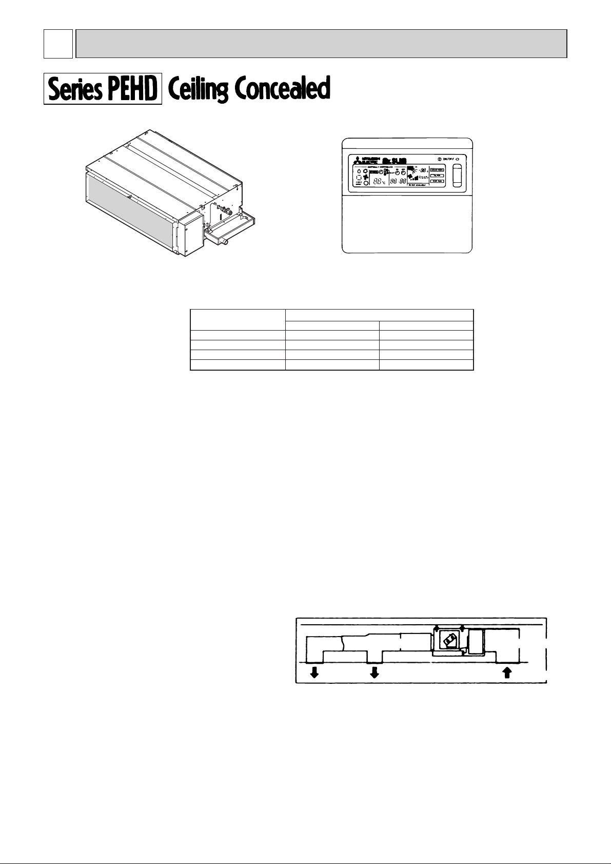
air outlet air outlet
Air outlet duct
Air intake duct
air intake
lndoor unit
Remote controller
Models Cooling capacity / Heating capacity
Btu/h W
PEHD-3EK(H)A3
PEHD-4EK(H)SA
3
PEHD-5EK(H)SA
3
PEHD-6EK(H)SA
26,300/30,700(37,900)
33,100/35,500(43,700)
42,300/47,400(57,700)
50,000/54,500(64,700)
7,700/9,000(11,100)
9,700/10,400(12,800)
12,400/13,900(16,900)
14,650/16,000(19,000)
Page 3
2
2
PART NAMES AND FUNCTIONS
6. ADVANCED MICROPROCESSOR
(1) Easy to use microprocessor
1) Ultra-thin remote controller
The streamlined, square controller is designed to blend well with any interior. Also, the sophisticated microprocessor allows you to easily carry out a wide range of operations.
2) Attractive liquid crystal display (LCD)
The unit's operation mode, set temperature, room temperature, timer setting, and fan speed are displayed on the
remote controller's easy-to-read Liquid Crystal Display (LCD)
3) Convenient 24-hour ON-OFF timer
The timer switches Mr.SLIM on and off automatically at the time you set. Once the timer is set, the remaining time
is shown on the LCD.
4) Self-diagnostic feature indicates faults instantly
If a problem occurs, the unit will stop operating and the set temperature indicator will change to a self-diagnostic
indicator, which shows the location of the trouble.
If the check switch is pressed twice, the unit stops operating and the check mode is initiated. The location of the
most recent problem that was stored in the memory is displayed on the LCD. This is extremely useful for
maintenance purposes.
5) Useful memory feature for storing instructions
The previous set value is memorized so that constant temperature control can be achieved. For example, if a
power failure occurs, the temperature will not have to be re adjusted afterwards.
(2) Non-polar two-wire remote controller cable
The slim, non-polar, two-wire remote controller cable makes installation simple and trouble free. Also, the remote
controller wire can be extended up to 500m.
(3) Automatic cooling/heating changeover operation
An automatic cooling and heating changeover operation system allows you to easily control comfortable year-round
air conditioning.
Once the desired temperature is set, unit operation switches automatically between cooling and heating, in
accordance with the room temperature. In addition, the use of an outdoor unit fan speed controller allows cooling even
when outdoor temperatures are as low as - 5˚C.
7. INNOVATIVE MICROPROCESSOR CONTROL SYSTEM
The most significant feature of PEHD-EK series is the advanced microprocessor control. The development of this system
is due to the recent world-wide trend in the air conditioning of larger buildings. They are moving away from centralized
duct systems to using individual split type units instead. There are a number of reasons for this change. First of all, the
duct's costly and troublesome installation is eliminated. Second, the overall air conditioning balance is excellent in split
type units. Lastly, the operation costs are low due to the flexible control of each unit. This system was developed
exclusively by Mitsubishi Electric because of high demand. The microprocessor control makes individual control, group
control, control using two remote controllers, and remote on/off and individual control possible without troublesome
equipment modifications.
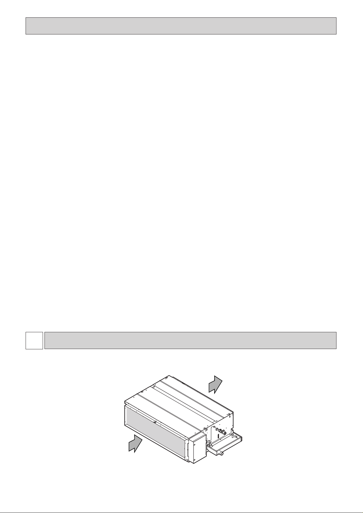
● Indoor Unit
Air intake
(sucks the air inside the room into the unit)
Air outlet
Page 4
3
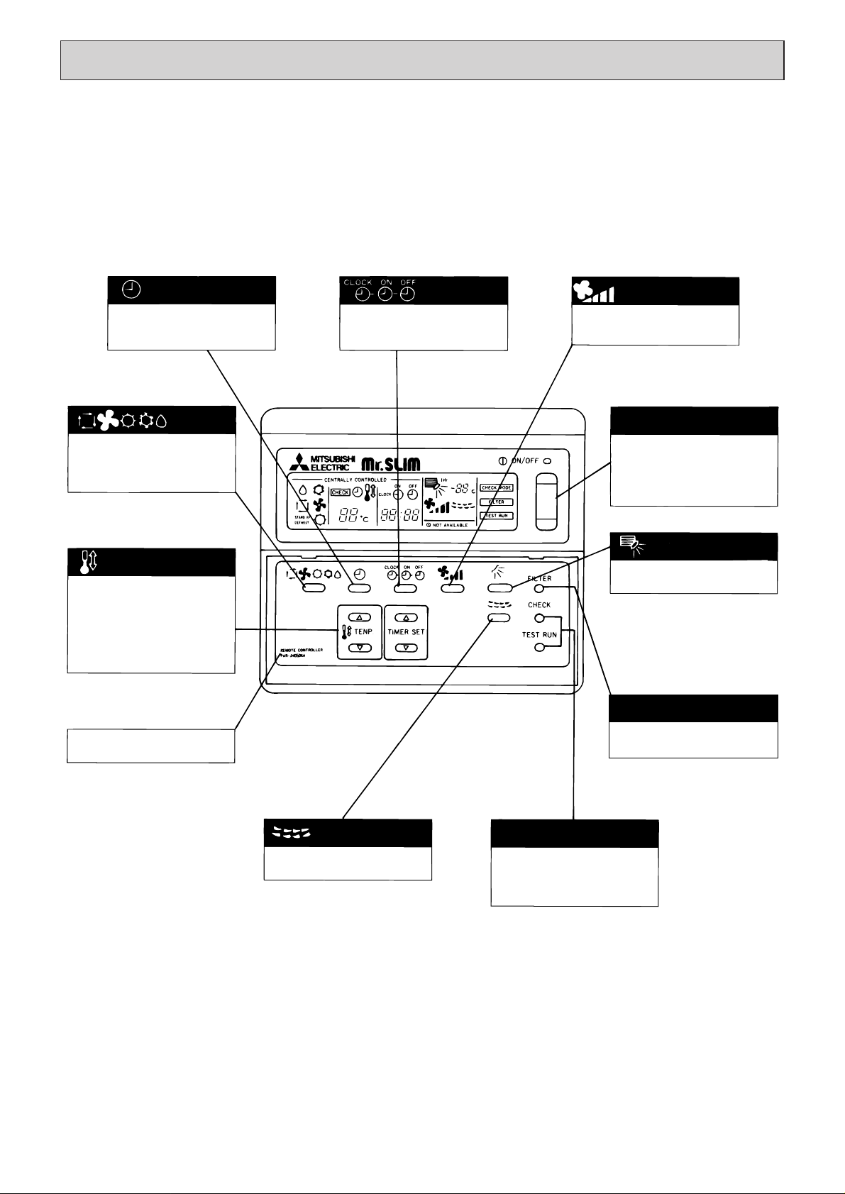
● Remote controller
● Once the operation of the unit is set, subsequent
operations can be performed only by pressing the
ON/OFF button repeatedly.
● Operation buttons
This switches between continuous operation and the timer
operation.
Press this button to switch the
cool, electronic dry (dehumidify)
automatic and heat modes.
This sets the room temperature. The temperature setting
can be performed in 1˚C
units.
Setting range :
Cool 19˚C to 30˚C
Heat 17˚C to 28˚C
The model name of the
remote controller is indicated.
This switches the horizontal
fan motion ON and OFF.
(This button does not operate
in this model)
Only press this button to perform an inspection check or
test operation. Do not use it
for normal operation.
This resets the filter service
indication display.
(This button dose not operate
in this model.)
This adjusts the vertical angle
of the ventilation.
(This button dose not operate
in this model)
This switches between the
operation and stop modes
each time it is pressed. The
lamp on this button lights during operation.
This sets / switches the current
time, start time and stop time.
This sets the ventilation fan
speed.
button
button
TEMP button
button
CHECK-TEST RUN
button
FILTER button
button
ON/OFF button
button
button
Page 5

4
● Display
This indicates when the unit
is controlled by optinal features such as central control
type remote controller.
The current time, start time
and stop time can be displayed in tencecond intervals
by pressing the time switch
button. The start time or stop
time is always displayed during
the timer operation.
The selected fan speed is displayed.
This indicates when the continuous operation and time
operation modes are set.
It also displays the time for
the timer operation at the
same time as when it is set.
This indicates the operation
mode.
This indicates when the stand
by mode is set from the time
the sleep operation starts
until the heating air discharges.
This indicates when the defrost operation is performed.
This indicates when a malfunction has occurred in the unit
which should be checked.
This displays the selected setting temperature.
The temperature of the suction air is displayed during
operation. The display range is
8˚C to 39˚C. The display flashes
8˚C when the actual temperature is less then 8˚C and
flashes 39˚C when the actual
temperature is greater then
39˚C.
This lamp lights during operation, goes off when the unit
stops and flashes when a malfunction occurs.
This display lights in the
check mode or when a test
operation is perfomed.
This lamp lights when electricity is supplied to the unit.
Caution
• Only the display lights whe the unit is stopped and power is supplied to the unit.
• When power is turned ON for the first time, the (CENTRAL CTRL) display appears to go off momentarily but this is not a
malfunction.
• When the central control remote control unit, which is sold separately, is used the ON - OFF button,
button and TEMP button do not operate.
• "NOT AVAILABLE" is displayed when the button and button are pressed. This indicates that this room
unit is not equipped with the fan direction adjustment function and the louver function.
CENTRALLY
CONTROLLED display
display
OPERATION MODE
display
STANDBY display
DEFROST display
CHECK display
Display
display
display
display
Operation lamp
CHECK MODE
TEST RUN
˚C
display
˚C
display
CLOCK
ON OFF
Page 6
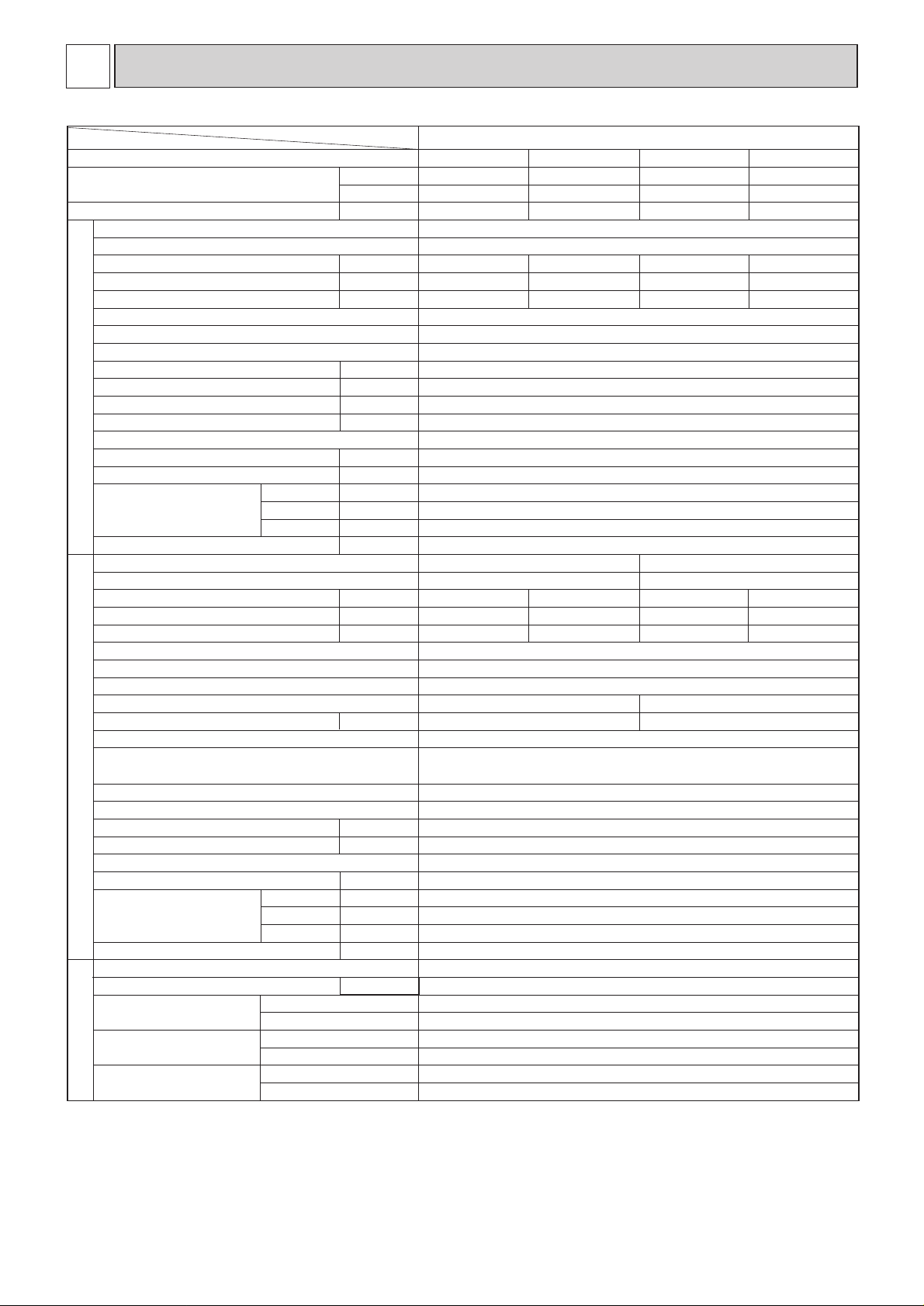
5
3
SPECIFICATION
Item
Function
Capacity
Total input
INDOOR UNIT
Model name
Power supply
Starting current
Running current
Input
External finish
Heat exchanger
Fan(drive) x No.
Fan motor output
Airflow(Low-High)
External static pressure
Booster heater
Operation control & Thermostat
Noise level(Low-High)
Cond.drain conn.O.D.
Dimensions
Weight
dB(A)
mm,(in)
mm,(in)
mm,(in)
mm,(in)
W
D
H
kg,(lbs)
Model name
Power supply
Input
Running current
Starting current
External finish
Refrigerant control
Compressor
Model
Motor output
kW
Protection devices
Stater type
Heat exchanger
Fan(drive) x No.
Fan motor output
kW
Airflow
CMM,(CFM)
Defrost method
Noise level
dB(A)
Dimensions
W
D
H
mm,(in)
mm,(in)
mm,(in)
kg,(lbs)
Weight
Refrigerant
kg,(lbs)
Charge
Pipe size O.D.
Connection method
Between the indoor
& outdoor unit
Liquid mm,(in)
Gas mm,(in)
Indoor side
Outdoor side
Height difference
Piping length
REFRIGERANT
PIPING
OUTDOOR UNIT
kW
A
A
Btu/h
W
kW
kW
A
A
kW
kW
CMM,(CFM)
Pa(mmAq)
Model
4
4
✻✻
✻
✻
✻
✻
✻
✻
✻
✻
✻
5
1
2
3
1. External static pressure at 130Pa
2. Ex-works at 70Pa(OPTION MOTOR: 130Pa)
3. External static pressure at 70Pa
4. Rating conditions <JIS B 8615, 8616>
(INDOOR) Cooling: 27˚CDB, 19˚CWB Heating: 20˚CDB
(OUTDOOR) Cooling: 35˚CDB Heating: 7˚CDB, 6˚CWB
5. Noise level: Sound pressure level
PEHD-3EK(H)A3.UK
Cooling
26,300
7,700
3.55
Cooling
26,300
7,700
3.55
Heating
PEHD-3EK(H)A
3.UK
~/N,50Hz, 220-240V
0.40
1.70
1.90
0.40 (2.50)
1.70 (10.41)
1.90 (10.65)
0.40
1.70
1.90
0.40 (2.50)
1.70 (10.41)
1.90 (10.65)
3N~, 380/220-415/240V, 50Hz~/N, 220-240V ,50Hz
Galvanized sheets
Plate fin coil
Centrifugal (direct)x2
0.15
20-25 (700-800)
70(7)/130(13) at Hi-notch
2.1
Remote control & Built-in
37-41
32 (1-1/4)
1,175 (46-1/8)
740 (29-1/8)
325 (12-13/16)
44 (97) [46 (101)]
PUH-3YKA
2PUH-3VKA2
3.15
13.82
58
2.94
12.89
58
3.15
5.16
37
2.94
4.81
37
Munsell 5Y7/1
Capillary tube
Hermetic
NH52VND NH52YDA
2.2 2.4
Line start
Plate fin coil
Propeller (direct)x2
0.085
50 (1764)
Reverse cycle
52
870 (34-1/4)
295+24 (11-5/8 add 1)
850 (33-7/16)
75 (165)
R-22
3.2 (7.1)
9.52 (3/8)
15.88 (5/8)
Flared
Flared
Max.50m
Max.50m
Heating
30,700 (37,900)
9,000 (11,100)
3.34 (5.44)
30,700 (37,900)
9,000 (11,100)
3.34 (5.44)
V: Inner thermostat,HP switch
Y: Reversed-phase protector, Thermal relay, Thermal switch, HP switch
Page 7
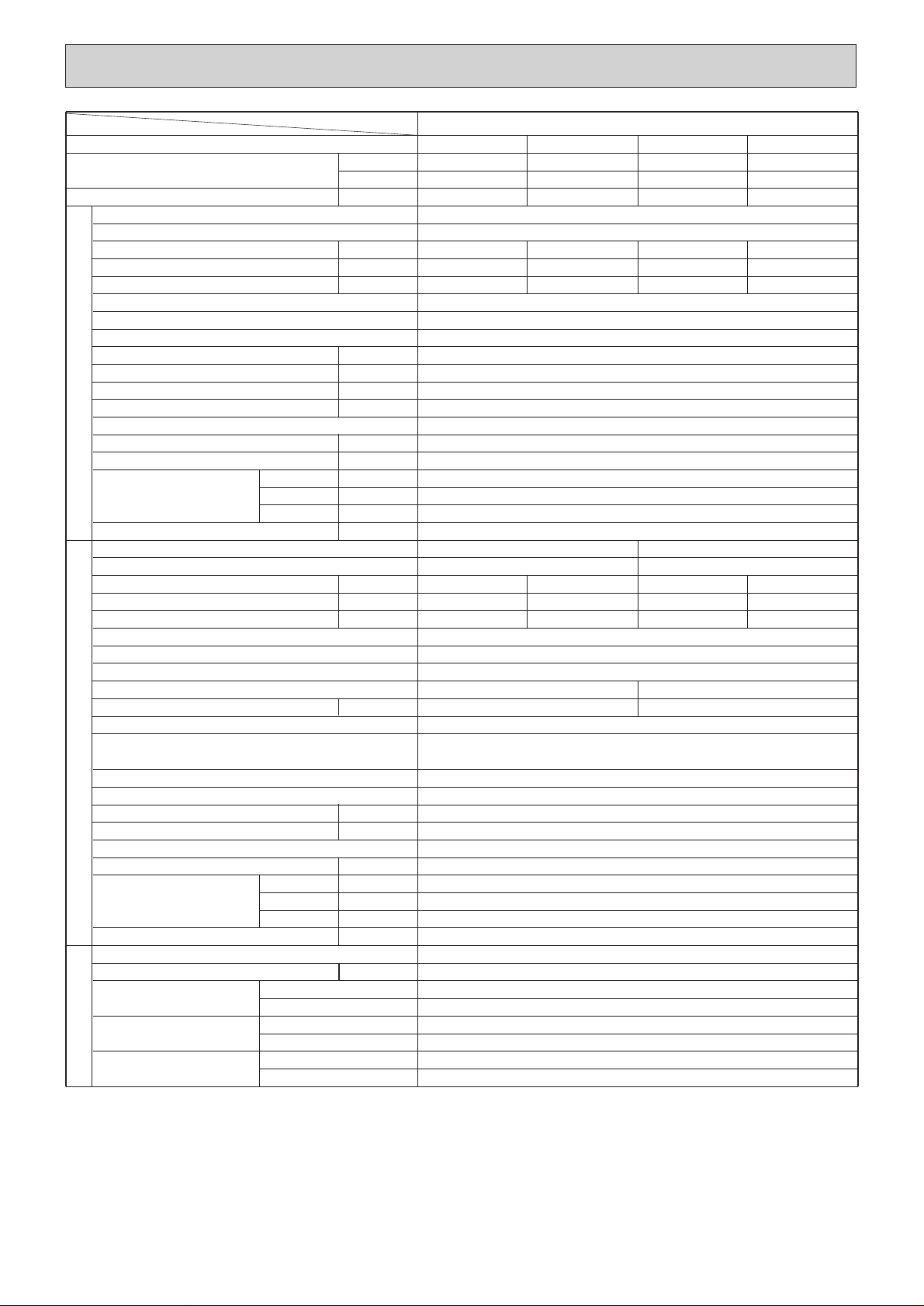
6
Item
Function
Capacity
Total input
Model name
Power supply
Input
Running current
Starting current
External finish
Heat exchanger
Fan(drive) x No.
Fan motor output
Airflow(Low-High)
External static pressure
Booster heater
INDOOR UNIT
Operation control & Thermostat
Noise level(Low-High)
Cond.drain conn.O.D.
Dimensions
Weight
Model name
Power supply
Input
Running current
Starting current
External finish
Refrigerant control
Compressor
Model
Motor output
Stater type
Protection devices
Heat exchanger
Fan(drive) x No.
OUTDOOR UNIT
Fan motor output
Airflow
Defrost method
Noise level
Dimensions
Weight
Refrigerant
Charge
Pipe size O.D.
PIPING
Connection method
REFRIGERANT
Between the indoor
& outdoor unit
Model
Cooling
✻
✻
W
kW
4
Btu/h
4
kW
A
A
kW
33,100
9,700
4.14
0.62
2.64
3.20
1
✻
CMM,(CFM)
Pa(mmAq)
2
✻
kW
✻✻
dB(A)
5
3
mm,(in)
W
D
H
mm,(in)
mm,(in)
mm,(in)
kg,(lbs)
~/N, 220-240V, 50Hz
kW
A
A
3.52
16.30
79
kW
V: Inner thermostat, HP switch
Y: Reversed-phase protector, Thermal relay, Thermal switch, HP switch
kW
CMM,(CFM)
dB(A)
W
D
H
mm,(in)
mm,(in)
mm,(in)
kg,(lbs)
kg,(lbs)
Liquid mm,(in)
Gas mm,(in)
Indoor side
Outdoor side
Height difference
Piping length
PEHD-4EK(H)SA3.UK
Heating
35,500 (43,700)
10,400 (12,800)
4.14 (6.54)
PEHD-4EK(H)SA
Cooling
33,100
9,700
3.82
3.UK
~/N, 50Hz, 220-240V
0.62 (3.02)
2.64 (12.58)
3.20 (13.2)
0.62
2.64
3.20
Galvanized sheets
Plate fin coil
Centrifugal (direct)x2
0.27
27-34 (950-1200)
70(7) / 130(13) at Hi-notch
2.4
Remote control & Built-in
41-46
32 (1-1/4)
1,415 (55-11/16)
740 (29-1/8)
325 (12-13/16)
62 (137) [65(143)]
PUH-4VKSA2
3N~, 380/220-415/240V, 50Hz
3.52
16.30
3.20
5.24
79
Munsell 5Y7/1
Capillary tube
Hermetic
NH56VNDT
2.7 .7
Line start
Plate fin coil
Propeller (direct) x2
0.065+0.065
95 (3350)
Reverse cycle
54
870 (34-1/4)
295+24 (11-5/8 and 1)
1258 (49-1/2)
94 (207)
R-22
4.2 (9.2)
9.52 (3/8)
19.05 (3/4)
Flared
Flared
Max.50m
Max.50m
PUH-4YKSA
40
NH56YDA
Heating
35,500 (43,700)
10,400 (12,800)
3.81 (6.21)
0.62 (3.02)
2.64 (12.58)
3.20 (13.2)
2
3.19
5.22
40
1. External static pressure at 130Pa
✻
2. Ex-works at 70Pa(OPTION MOTOR: 130Pa)
✻
✻
3. External static pressure at 70Pa
4. Rating conditions <JIS B 8615, 8616>
✻
(INDOOR) Cooling: 27˚CDB, 19˚CWB Heating: 20˚CDB
(OUTDOOR) Cooling: 35˚CDB Heating: 7˚CDB, 6˚CWB
5. Noise level: Sound pressure level
✻
Page 8
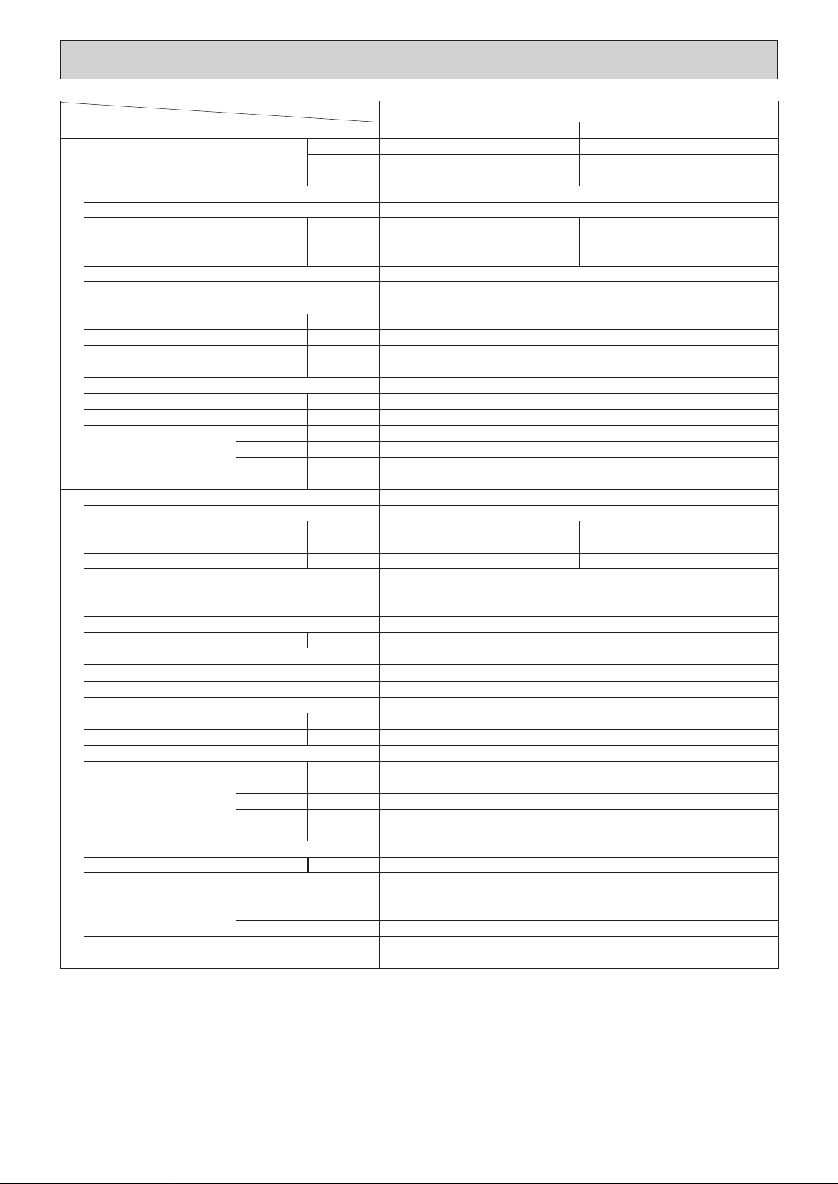
7
Item
Function
Capacity
Total input
Model name
Power supply
Input
Running current
Starting current
External finish
Heat exchanger
Fan(drive) x No.
Fan motor output
Airflow(Low-High)
External static pressure
Booster heater
INDOOR UNIT
Operation control & Thermostat
Noise level(Low-High)
Cond.drain conn.O.D.
Dimensions
Weight
Model name
Power supply
Input
Running current
Starting current
External finish
Refrigerant control
Compressor
Model
Motor output
Stater type
Protection devices
Heat exchanger
Fan(drive) x No.
OUTDOOR UNIT
Fan motor output
Airflow
Defrost method
Noise level
Dimensions
Weight
Refrigerant
Charge
Pipe size O.D.
PIPING
Connection method
REFRIGERANT
Between the indoor
& outdoor unit
Model
✽
✽
Btu/h
4
4
W
kW
kW
A
A
kW
CMM,(CFM)
Pa(mmAq)
kW
✽
dB(A)
5
mm,(in)
W
D
H
mm,(in)
mm,(in)
mm,(in)
kg,(lbs)
kW
A
A
kW
kW
CMM,(CFM)
dB(A)
W
D
H
mm,(in)
mm,(in)
mm,(in)
kg,(lbs)
kg,(lbs)
Liquid mm,(in)
Gas mm,(in)
Indoor side
Outdoor side
Height difference
Piping length
PEHD-5EK(H)SA3.UK
Cooling
42,300
12,400
4.85
PEHD-5EK(H)SA
3.UK
Heating
47,400 (57,700)
13,900 (16,900)
4.80 (7.80)
~/N, 50Hz, 220-240V
0.64
2.72
6.00
0.64 (3.64)
2.72 (15.17)
6.00 (18.50)
Galvanized sheets
Plate fin coil
Centrifugal (direct)x2
✽
1
0.30
33.5-42 (1180-1480)
✽
2
70(7) /130(13) at Hi-notch
3.0
Remote control & Built-in
✽
3
44-50
32 (1-1/4)
1,415 (55-11/16)
740 (29-1/8)
325 (12-13/16)
65(143) [68(150)]
PUH-5YKSA
2
3N~, 380/220-415/240V, 50Hz
4.21
6.89
53
4.16
6.81
53
Munsell 5Y7/1
Capillary tube
Hermetic
ZR-61K3-TFD
3.5
Line start
Internal thermostat, Anti-phase protector, Thermal switch, HP switch
Plate fin coil
Propeller(direct)x2
0.085+0.085
95 (3350)
Reverse cycle
55
970 (38-3/16)
345+24 (13-9/16 add 1)
1258 (49-1/2)
114 (251)
R-22
5.4 (11.9)
9.52 (3/8)
19.05 (3/4)
Flared
Flared
Max.50m
Max.50m
✽
1. External static pressure at 130Pa
✽
2. Ex-works at 70Pa(OPTION MOTOR: 130Pa)
✽
3. External static pressure at 70Pa
✽
4. Rating conditions < JIS B 8615, 8616>
(INDOOR) Cooling: 27˚CDB, 19˚CWB Heating: 20˚CDB
(OUTDOOR) Cooling: 35˚CDB Heating: 7˚CDB, 6˚CWB
✽
5. Noise level: Sound pressure level
Page 9
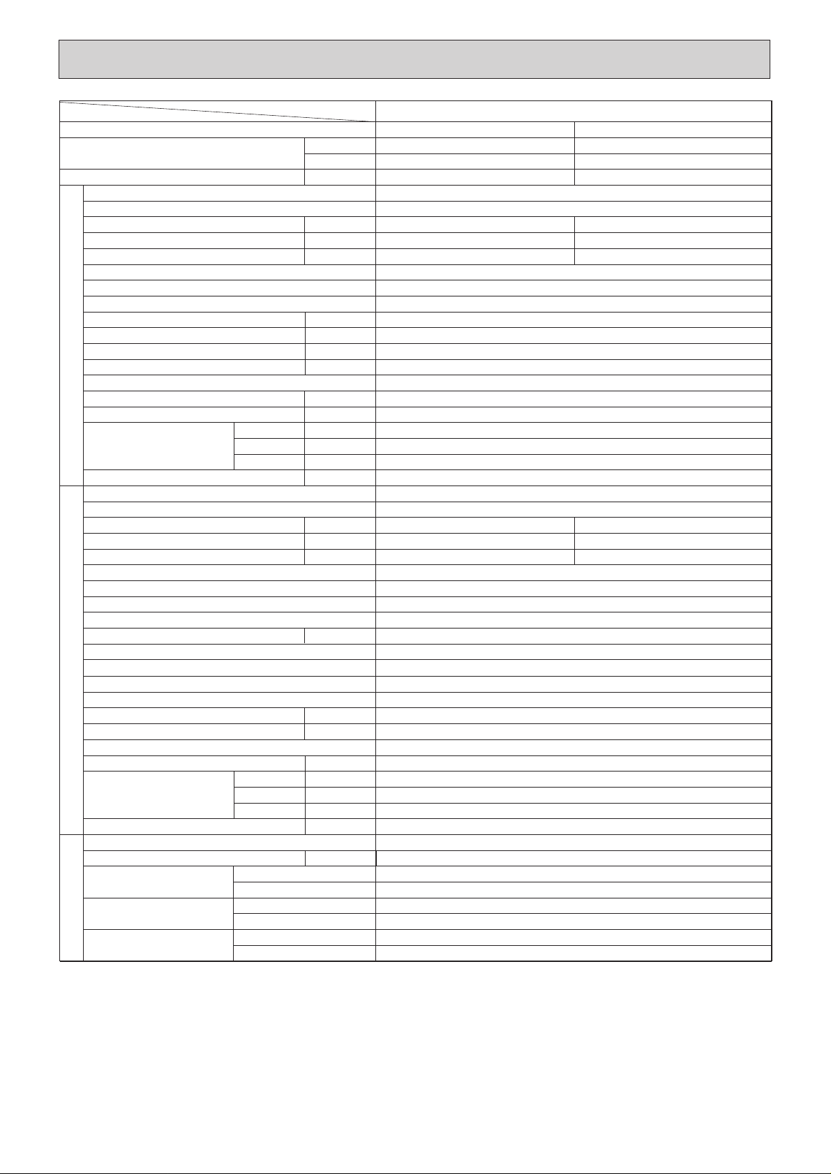
8
Item
Function
Capacity
Total input
Model name
Power supply
Input
Running current
Starting current
External finish
Heat exchanger
Fan(drive) x No.
Fan motor output
Airflow(Low-High)
External static pressure
Booster heater
INDOOR UNIT
Operation control & Thermostat
Noise level(Low-High)
Cond.drain conn.O.D.
Dimensions
Weight
Model name
Power supply
Input
Running current
Starting current
External finish
Refrigerant control
Compressor
Model
Motor output
Stater type
Protection devices
Heat exchanger
Fan(drive) x No.
OUTDOOR UNIT
Fan motor output
Airflow
Defrost method
Noise level
Dimensions
Weight
Refrigerant
Charge
Pipe size O.D.
PIPING
Connection method
REFRIGERANT
Between the indoor
& outdoor unit
Model
✽ 4
✽ 4
Btu/h
W
kW
kW
A
A
kW
CMM,(CFM)
Pa(mmAq)
kW
✽ 5
dB(A)
mm,(in)
W
D
H
mm,(in)
mm,(in)
mm,(in)
kg,(lbs)
kW
A
A
kW
kW
CMM,(CFM)
dB(A)
W
D
H
mm,(in)
mm,(in)
mm,(in)
kg,(lbs)
kg,(lbs)
Liquid mm,(in)
Gas mm,(in)
Indoor side
Outdoor side
Height difference
Piping length
PEHD-6EK(H)SA.UK
Cooling
50,000
14,650
5.39
Heating
54,500 (64,700)
16,000 (19,000)
5.24 (8.24)
PEHD-6EK(H)SA.UK
~ /N,50Hz,220-240V
0.66
2.79
6.25
0.66 (3.66)
2.79 (15.24)
6.25 (18.75)
Galvanized sheets
Plate fin coil
Centrifugal (direct)x2
✽ 1
0.30
36.5-46 (1,280-1,620)
✽ 2
70(7) / 130(13) at Hi-notch
3.0
Remote control & Built-in
✽ 3
46-51
32 (1-1/4)
1,715 (67-1/2)
740 (29-1/8)
325 (12-13/16)
70(154) [ 73(161)]
PUH-6YKSA
2.UK
3N~ , 380/220-415/240V, 50Hz
4.73
7.74
74
4.58
7.50
74
Munsell 5Y7/1
Capillary tube
Hermetic
ZR68KC-TFD
4.0
Line start
Internal thermostat, Anti-phase protector, Thermal switch, HP switch
Plate fin coil
Propeller(direct)x 2
0.10+ 0.10
100 (3530)
Reverse cycle
56
970 (38-3/16)
345+ 24 (13-9/16 and 1)
1,258 (49-1/2)
117 (258)
R-22
5.0 (11.0)
9.52 (3/8)
19.05 (3/4)
Flared
Flared
Max.50m
Max.50m
✽ 1. External static pressure at 130Pa
✽ 2. Ex-works at 70Pa(OPTION MOTOR: 130Pa)
✽ 3. External static pressure at 70Pa
✽ 4. Rating conditions < JIS B 8615, 8616>
(INDOOR) Cooling: 27˚CDB, 19˚CWB Heating: 20˚CDB
(OUTDOOR) Cooling: 35˚CDB Heating: 7˚CDB, 6˚CWB
✽ 5. Noise level: Sound pressure level
Page 10
9
4
DA T A
Service Ref.
Indoor
intake air
WB˚C
20 25 30 35 40 45
CA P.C. CA P.C. CA P.C. CA P.C. CA P.C. CA P.C.
14,782 4.32 14,372 4.50 13,844 4.86 13,273 5.20 12,731 5.55 12,116 5.90
15,734 4.40 15,324 4.60 14,767 4.96 14,177 5.33 13,581 5.69 12,951 6.05
16,701 4.49 16,305 4.68 15,734 5.07 15,119 5.45 14,489 5.84 13,844 6.24
17,683 4.58 17,346 4.78 16,745 5.17 16,115 5.58 15,456 6.00 14,782 6.44
16
18
20
22
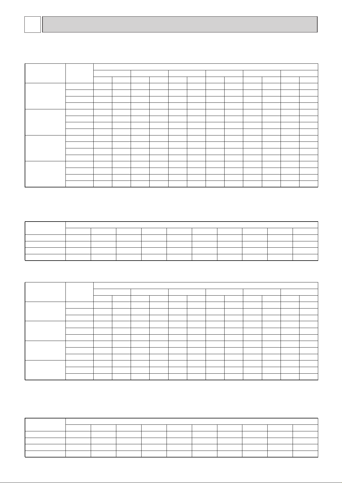
1. PERFORMANCE DATA
1) COOLING CAPACITY
Note C A: Capacity(W)
P.C.: Power consumption(kW)
PEHD-6EK(H)SA.UK
Service Ref.
PEHD-6EK(H)SA.UK
Refrigerant piping length(one way)
5m 10m 15m 20m 25m 30m 35m 40m 45m 50m
1.00 0.975 0.955 0.935 0.918 0.900 0.884 0.869 0.855 0.840
Cooling capacity correction factors
Service Ref. -10 -5 0 5 10 15
10,957 3.58 12,557 3.95 14,313 4.35 16,220 4.78 18,277 5.22 20,480 5.69
10,492 3.85 12,064 4.26 13,773 4.69 15,616 5.14 17,590 5.63 19,695 6.13
10,083 4.09 11,574 4.54 13,227 5.01 15,037 5.51 17,006 6.03 19,131 6.58
15
20
25
2) HEATING CAPACITY
Indoor
intake air
WB˚C
Outdoor intake air DB˚C
PEHD-6EK(H)SA.UK
CA P.C. CA P.C. CA P.C. CA P.C. CA P.C. CA P.C.
Note C A : Capacity(W)
P.C.: Power consumption(kW)
Service Ref.
PEHD-6EK(H)SA.UK
Refrigerant piping length(one way)
5m 10m 15m 20m 25m 30m 35m 40m 45m 50m
1.00 1.00 1.00 1.00 1.00 1.00 0.998 0.995 0.993 0.990
Heating capacity correction factors
PEHD-3EK(H)A3.UK
PEHD-4EK(H)SA
3.UK
PEHD-5EK(H)SA
3.UK
7,839 2.87 7,623 3.00 7,315 3.21 6,984 3.43 6,637 3.64 6,283 2.9016
8,339 2.94 8,124 3.06 7,792 3.29 7,454 3.51 7,099 3.74 6,738 3.1018
8,847 2.98 8,639 3.11 8,301
8,832
9,215
3.35 7,946 3.60 7,585 3.83 7,215 3.3320
9,363 3.04 9,186 3.18 3.43 8,470 3.68 8,100 3.94 7,715 3.5622
9,875 3.09 9,603 3.23 3.46 8,798 3.69 8,361 3.92 7,915 3.1116
10,505 3.16 10,234 3.29 9,816 3.54 9,390 3.78 8,943 4.02 8,488 3.3418
11,145 3.20 10,883 3.34 10,457 3.61 10,010 3.87 9,555 4.12 9,089 3.5820
11,795 3.26 11,572 3.41 11,126 3.69 10,670 3.96 10,204 4.24 9,719 3.8322
12,623 3.92 12,276 4.10 11,780 4.39 11,247 4.68 10,689 4.98 10,118 3.9616
13,429 4.01 13,083 4.18 12,549 4.49 12,003 4.80 11,433 5.11 10,851 4.2518
14,247 4.07 13,913 4.25 13,367 4.58 12,797 4.91 12,215 5.24 11,619 4.5420
15,078 4.15 14,793 4.34 14,223 4.68 13,640 5.03 13,045 5.38 12,425 4.8622
PEHD-3EK(H)A3.UK
PEHD-4EK(H)SA
3.UK
PEHD-5EK(H)SA
3.UK
PEHD-3EK(H)A
3.UK
PEHD-4EK(H)SA
3.UK
PEHD-5EK(H)SA
3.UK
1.00 0.981 0.968 0.952 0.940 0.925 0.913 0.900 0.886 0.874
1.00 0.989 0.980 0.970 0.960 0.950 0.940 0.930 0.920 0.910
1.00 0.981 0.968 0.952 0.940 0.925 0.913 0.900 0.886 0.874
6,245 2.35 7,128 2.59 8,091 2.84 9,136 3.10 10,251 3.38 11,439 4.3715
5,975 2.53 6,849 2.78 7,786 3.05 8,793 3.34 9,865 3.64 11,007 4.2020
5,751 2.69 6,570 2.97 7,479 3.27 8,469 3.57 9,540 3.90 10,683 4.0925
7,217 2.60 8,237 2.86 9,350 3.14 10,557 3.43 11,846 3.74 13,218 4.8415
6,905 2.81 7,914 3.08 8,997 3.38 10,161 3.70 11,399 4.03 12,719 4.6620
6,646 2.98 7,592 3.29 8,642 3.62 9,786 3.96 11,024 4.32 12,345 4.5225
9,646 3.28 11,009 3.60 12,497 3.96 14,110 4.32 15,833 4.72 17,666 6.1015
9,229 3.53 10,577 3.88 12,025 4.26 13,581 4.66 15,235 5.08 16,999 5.8720
8,883 3.76 10,147 4.15 11,550 4.56 13,079 4.99 14,734 5.44 16,500 5.7025
PEHD-3EK(H)A3.UK
PEHD-4EK(H)SA
3.UK
PEHD-5EK(H)SA
3.UK
1.00 1.00 1.00 1.00 1.00 1.00 0.998 0.995 0.993 0.990
1.00 1.00 1.00 1.00 1.00 1.00 0.998 0.995 0.993 0.990
1.00 1.00 1.00 1.00 1.00 1.00 0.998 0.995 0.993 0.990
Page 11

10
2. PERFORMANCE CURVE
PEHD-3EK(H)A
3.UK
PEHD-4EK(H)SA
3.UK
PEHD-5EK(H)SA
3.UK
PEHD-6EK(H)SA.UK
Cooling
1.4
1.2
1
0.8
0.6
1.4
1.2
1
0.8
0.6
0.4
1.4
1.2
1
0.8
0.6
1.4
1.2
1
0.8
0.6
0.4
22
20
18
16
22
20
18
16
INDOOR WB
(˚C)
INDOOR WB
(˚C)
INDOOR DB
(˚C)
INDOOR DB
(˚C)
CAPACITY(RATIO)
CAPACITY(RATIO)
TOTAL INPUT(RATIO)
TOTAL INPUT(RATIO)
OUTDOOR DB
(˚C)
OUTDOOR WB
(˚C)
-12 -10 -5 0 5 10 15
-5 5 15 25 35 46
Heating
15
20
25
25
20
15
Page 12

3. FAN PERFORMANCE AND CORRECTED AIR FLOW
11
PEHD-3EK(H)A3.UK
Fan performance <130pa>
Recommended range
200
180
160
140
120
100
=
80
(1Pa 0.1mmAg)
60
Extemal static pressure (Pa)
40
20
12 16 20 24 28 32
Air flow
Corrected Air Flow
Cooling
1.1
Lo
Hi
(CMM)
Capacity
Input
1.3
1.2
Fan performance <70pa>
Recommended range
180
160
140
120
100
80
=
60
(1Pa 0.1mmAg)
40
20
Extemal static pressure (Pa)
12 16 20 24 28 32
Air flow
Heating
Lo
Hi
(CMM)
1.0
0.9
Correction factor
0.8
12 16 20 24 28 32
Air flow (CMM)
PEHD-4EK(H)SA3.UK
Fan performance <130pa>
Recommended range
200
180
160
140
120
100
=
80
(1Pa 0.1mmAg)
60
Extemal static pressure (Pa)
40
20
Corrected Air Flow
Lo
26 28 30 32 34 36 38 40
Air flow
Cooling
1.1
Hi
(CMM)
Correction factor
Capacity
Input
1.1
1.0
0.9
0.8
12 16 20 24 28 32
Air flow (CMM)
Fan performance <70pa>
Recommended range
220
200
180
160
140
120
100
=
80
(1Pa 0.1mmAg)
60
Extemal static pressure (Pa)
40
20
24 26 28 30 32 34 36 38
1.2
1.1
Lo
Air flow
Heating
Hi
(CMM)
1.0
0.9
Correction factor
0.8
24 26 28 30 32 34 36 38 40
Air flow (CMM)
1.0
0.9
Correction factor
0.8
24 26 28 30 32 34 36 38 40
Air flow (CMM)
Page 13

12
PEHD-5EK(H)A3.UK
Fan performance <130pa>
=
(1Pa 0.1mmAg)
Extemal static pressure (Pa)
Recommended range
220
200
180
160
140
120
100
80
60
40
20
Lo
Hi
Fan performance <70pa>
Recommended range
220
200
180
160
140
120
100
=
80
(1Pa 0.1mmAg)
60
Extemal static pressure (Pa)
40
20
Lo
Hi
32 34 36 38 40 42 44 46 48
Air flow
Corrected Air Flow
Cooling
1.1
1.0
0.9
Correction factor
0.8
32 34 36 38 40 42 44 46 48
PEHD-6EK(H)SA.UK
Fan performance <130pa>
=
(1Pa 0.1mmAg)
Extemal static pressure (Pa)
Recommended range
220
200
180
160
140
120
100
80
60
40
20
Lo
38 40 42 44 46 48 50
36
Air flow
(CMM)
Air flow (CMM)
(CMM)
Hi
52
Capacity
Input
32 34 36 38 40 42 44 46
Air flow
Heating
1.2
1.1
1.0
0.9
Correction factor
0.8
32 34 36 38 40 42 44 46 48
(CMM)
Fan performance <70pa>
Recommended range
200
180
160
140
120
100
=
80
(1Pa 0.1mmAg)
60
40
Extemal static pressure (Pa)
20
Lo
36
38 40 42 44 46 48
Air flow
Air flow (CMM)
Hi
50
(CMM)
Corrected Air Flow Capacity
Cooling
1.1
1.0
0.9
Correction factor
0.8
36 38 40 42 44 46
Air flow (CMM)
Input
48 50
52
Heating
1.2
1.1
1.0
0.9
Correction factor
0.8
36 38 40 42 44 46
Air flow (CMM)
48
50 52
Page 14

13
4. ELECTRICAL DATA
Models
Indoor
Outdoor
Mode
Capacity(W)
Total input(kW)
Input(kW)
Current(A)
Starting current(A)
Input(kW)
Current(A)
Starting current(A)
IndoorOutdoor
PUH-6YKSA
PEHD-6EK(H)SA.UK
Cool
14,300
5.20
0.56
2.59
5.75
4.64
8.10
68
Heat
15,800
(18,300)
5.12
(7.62)
0.56
(3.06)
2.59
(13.91)
5.75
(17.11)
4.56
7.96
68
Indoor ······220V 50Hz 1phase
Outdoor ···220/380V 50Hz 1/3phases
Models
Indoor
Outdoor
Mode
Capacity(W)
Total input(kW)
Input(kW)
Current(A)
Starting current(A)
Input(kW)
Current(A)
Starting current(A)
IndoorOutdoor
PUH-6YKSA
PEHD-6EK(H)SA.UK
Cool
14,500
5.30
0.61
2.69
6.00
4.69
7.87
71
Heat
15,900
(18,600)
5.18
(7.88)
0.61
(3.31)
2.69
(14.37)
6.00
(17.74)
4.57
7.67
71
Indoor ······230V 50Hz 1phase
Outdoor···230/400V 50Hz 1/3phases
Models
Indoor
Outdoor
Mode
Capacity(W)
Total input(kW)
Input(kW)
Current(A)
Starting current(A)
Input(kW)
Current(A)
Starting current(A)
IndoorOutdoor
PUH-6YKSA
PEHD-6EK(H)SA.UK
Cool
14650
5.39
0.66
2.79
6.25
4.73
7.74
74
Heat
16000
(19000)
5.24
(8.24)
0.66
(3.66)
2.79
(15.24)
6.25
(18.75)
4.58
7.50
74
Indoor·······240V 50Hz 1phase
Outdoor···240/415V 50Hz 1/3phases
PEHD-4EK(H)SA3.UKPEHD-3EK(H)A3.UK PEHD-5EK(H)SA3.UK
PUH-4YKSAPUH-4VKSAPUH-3YKA
PUH-5YKSA
PUH-3VKA
Cool
12,200
4.73
0.54
2.50
5.50
4.19
7.32
49
Heat
13,700
(16,200)
4.67
(7.17)
0.54
(3.04)
2.50
(13.82)
5.50
(16.86)
4.13
7.21
49
Cool HeatCool
9,500
3.87
0.52
2.41
2.93
3.35
16.90
79
Heat
10,200
(12,200)
3.87
(5.87)
0.52
(2.52)
2.41
(11.45)
2.93
(12.02)
3.35
16.90
79
9,500
3.69
0.52
2.41
2.93
3.17
5.29
37
10,200
(12,200)
3.68
(5.68)
0.52
(2.52)
2.41
(11.45)
2.93
(12.02)
3.16
5.28
37
Cool
7,500
3.43
0.30
1.39
1.74
3.13
14.67
54
Heat
8,900
(10,700)
3.22
(5.02)
0.30
(2.10)
1.39
(9.55)
1.74
(9.92)
2.92
13.68
54
Cool
7,500
3.43
0.30
1.39
1.74
3.13
5.23
34
Heat
8,900
(10,700)
3.22
(5.02)
0.30
(2.10)
1.39
(9.55)
1.74
(9.92)
2.92
4.88
34
PEHD-4EK(H)SA3.UKPEHD-3EK(H)A3.UK PEHD-5EK(H)SA3.UK
PUH-4YKSAPUH-4VKSAPUH-3YKA
PUH-5YKSA
PUH-3VKA
Cool
12,300
4.79
0.59
2.62
5.75
4.20
7.05
51
Heat
13,800
(16,500)
4.74
(7.44)
0.59
(3.29)
2.62
(14.30)
5.75
(17.49)
4.15
6.97
51
Cool
9,600
4.01
0.57
2.53
3.07
3.44
16.60
79
Heat
10,300
(12,500)
4.01
(6.21)
0.57
(2.77)
2.53
(12.64)
3.07
(12.64)
3.44
16.60
79
Cool
9,600
3.76
0.57
2.53
3.07
3.19
5.23
39
Heat
10,300
(12,500)
3.75
(5.95)
0.57
(2.77)
2.53
(12.64)
3.07
(12.64)
3.18
5.22
39
Cool
7,600
3.49
0.35
1.55
1.82
3.14
14.22
56
Heat
8,950
(10,850)
3.28
(5.18)
0.35
(2.25)
1.55
(9.78)
1.82
(10.08)
2.93
13.27
56
Cool
7,500
3.49
0.35
1.55
1.82
3.14
5.21
36
Heat
8,950
(10,850)
3.28
(5.18)
0.35
(2.25)
1.55
(9.78)
1.82
(10.08)
2.93
4.86
36
PEHD-4EK(H)SA3.UKPEHD-3EK(H)A3.UK PEHD-5EK(H)SA3.UK
PUH-4YKSAPUH-4VKSAPUH-3YKA
PUH-5YKSA
PUH-3VKA
Cool
12,400
4.85
0.64
2.72
6.00
4.21
6.89
53
Heat
13,900
(16,900)
4.80
(7.80)
0.64
(3.64)
2.72
(15.17)
6.00
(18.50)
4.16
6.81
53
Cool
9,700
4.14
0.62
2.64
3.20
3.52
16.30
79
Heat
10,400
(12,800)
4.14
(6.54)
0.62
(3.02)
2.64
(12.58)
3.20
(13.20)
3.52
16.30
79
Cool
9,700
3.82
0.62
2.64
3.20
3.20
5.24
40
Heat
10,400
(12,800)
3.81
(6.21)
0.62
(3.02)
2.64
(12.58)
3.20
(13.20)
3.19
5.22
40
Cool
7,700
3.55
0.40
1.70
1.90
3.15
13.82
58
Heat
9,000
(11,100)
3.34
(5.44)
0.40
(2.50)
1.70
(10.41)
1.90
(10.65)
2.94
12.89
58
Cool
7,700
3.55
0.40
1.70
1.90
3.15
5.16
37
Heat
9,000
(11,100)
3.34
(5.44)
0.40
(2.50)
1.70
(10.41)
1.90
(10.65)
2.94
4.81
37
Page 15

14
5. STANDARD OPERATION DATA
5
REFRIGERANT SYSTEM DIAGRAM
Indoor unit
Indoor
heat
exchanger
Strainer
Restrictor
valve
Thermistor
TH2
Distributor
with strainer
Capillary
tube
PEHD-3(OD4.0xID2.0xL400)
PEHD-4(OD4.0xID2.4xL550)
PEHD-5(OD4.0xID2.4xL350)
PEHD-6(OD4.0xID2.4xL300)
Refrigerant flow in cooling R.V.coil
Refrigerant flow in heating Heating : ON
Cooling : OFF
Unit : mm
PEHD-3EK(H)A3.UK
PEHD-4EK(H)SA
3.UK
PEHD-5EK(H)SA
3.UK
PEHD-6EK(H)SA.UK
Models
Mode
TotalElectrical circuitRefrigerant circuit
Indoor side
Outdoor
side
SHF
BF
Capacity
Input
Indoor unit model
Phase . Hz
Volts
Amperes
Outdoor unit-model
Phase,Hz
Volts
Amperes
W
kW
Discharge pressure
Suction pressure
Discharge temperature
Condensing temperature
Suction temperature
Ref.Pipe length
Intake air temperature
Intake air temperature
Discharge air temperature
MPa
MPa
˚C
˚C
˚C
m
DB˚C
WB˚C
DB˚C
DB˚C
WB˚C
PEHD-6EK(H)SA.UK
Cooling Heating
14,400 16,000
5.39 5.24
PEHD-6EK(H)SA
1 . 50
240
2.79 2.79
PUH-6YKSA
3.50
415
7.74 7.50
2.00 1.74
0.47 0.36
84.5 71.6
52.7
-
5.6 -2.3
55
27 20
19 15
14.2 40.1
35 7
24 6
0.77
-
0.11
-
Cooling Heating
12,400 13,900
4.85 4.80
PEHD-5EK(H)SA
1 . 50
240
2.72 2.72
PUH-5YKSA
3.50
415
6.89 6.81
1.88 1.70
0.51 0.37
75.8 74.3
48.8
-
6.8
55
27 20
19 15
15.1 37.0
35 7
24 6
0.85
-
0.13
-
Cooling Heating
7,700 9,000
3.55 3.34
PEHD-3EK(H)A
1 . 50
240
1.70 1.70
PUH-3YKA
3.50
415
5.16 4.81
2.00 1.84
0.45 0.34
86.3 81.7
52.1
-
4.8 -2.8
55
27 20
19 15
15.2 37.8
35 7
24 6
0.78
-
0.20
-
Cooling Heating
7,700 9,000
3.55 3.34
PEHD-3EK(H)A
1 . 50
240
1.70 1.70
PUH-3VKA
1.50
240
13.82 12.89
2.04 1.86
0.47 0.34
89.6 83.9
53.1
-
4.2 -3.8
55
27 20
19 15
15.3 37.8
35 7
24 6
0.78
-
0.21
-
Cooling Heating
9,700 10,400
3.82 3.81
PEHD-4EK(H)SA
1 . 50
240
2.64 2.64
PUH-4YKSA
3.50
415
5.24 5.22
1.86 1.70
0.53 0.38
77.7 74.3
49.2
-
7.6 -1.3 -1.7
55
27 20
19 15
15.8 36.1
35 7
24 6
0.80
-
0.22
-
Cooling Heating
9,700 10,400
4.14 4.14
PEHD-4EK(H)SA
1 . 50
240
2.64 2.64
PUH-4VKSA
1.50
240
16.30 16.30
1.88 1.71
0.49 0.36
83.3 80.1
51.5
-
7.5 -1.5
55
27 20
19 15
15.8 36.3
35 7
24 6
0.80
-
0.22
-
PEHD-4EK(H)SA3.UKPEHD-3EK(H)A3.UK PEHD-5EK(H)SA3.UK
Page 16

15
6
OUTLINES & DIMENSIONS
1. INDOOR UNIT(PEHD-6)
210
12-ø3
450
450
140
282
680
3 3
30
319
261
181 40
30
A
C B 81
10
375
10
80
C B 81
A
E 13
30
D
20
35
30
1053 169
307
113
122
12-ø3
(14x22)
Lifting bolt hole
45
163
323
308
44 75
7
6
5
13
Keep duct-work length 850mm or more.
Be sure to apply the air filter (field supply) near the air inlet grille.
Service space:500 or more
81
365~465
197
81
50~150
55
Access door
Air outlet
Air inlet
3
1
2
4
Refrigerant piping flare connection (liquid ø9.52 copper tube) : HP
Refrigerant piping flare connection (gas øF copper tube) : LP
Drain 25A (male screw)
Electrical parts box
Electric Heater ··· Only PEHD-EKH(S)A Type
Drain Pump (Option)
Drain Pipe (Option) ··· Use VP25 (O.D.ø32 PVC TUBE) )
Set
1
2
3
4
5
6
7
Model
PEHD-3
PEHD-4·5
PEHD-6
A
1012
1252
1552
B
280
360
460
C
290
370
470
D
1070
1310
1610
E
1044
1284
1584
F
15.88
19.05
19.05
2. REMOTE CONTROLLER
Unit:mm (inch)
Rear side wiring arangement opening
46
83.5
130
18
120
PEHD-3EK(H)A3.UK
PEHD-4EK(H)SA3.UK
PEHD-5EK(H)SA
3.UK
PEHD-6EK(H)SA.UK
Page 17

16
7
WIRING DIAGRAM
MODELS:PEHD-3EK(H)A3, PEHD-4EK(H)SA3, PEHD-5EK(H)SA3, PEHD-6EK(H)SA WIRING DIAGRAM
SW3SW5
OFF
ON
WHT
YLW
BRN
AC10.8V
T
RED
BRN
WHT
2
1
DP
2
35
RED
ORN
MF
External static
pressure 130Pa pressure 70Pa
BRN
41
C
X3X2X1 X6X5X4
M3
BLK
GRN/YLW
2
53
6
BLK
External static
TH2
65
CN2L
LOSSNAY
CN21
PIPE
SW2
TH1
CN20
INTAKE
SW6
CN50
DRAIN
1122
2
4135
BLU
BLK
BLK
GRY
GRY
1
32
4
DS
RED
YLW
91043 1287564312431243 124321
CN4T
TRANS
RED
AC14.5V
ORN
SW1
BRN
✽
#········ Option parts
C
CN1<R.B>
CN2<R.B>
CN2L<R.B>
CN51<R.B>
F<I.B>
FS1,FS2
✽
H
✽
I.B
LCD
MF
R.B
SW1(I.B)
SW2(I.B)
SW3(I.B)
SW5(I.B)
SW6(I.B)
Capacitor (fan motor)
Connector (program timer)
Connector (remote switch)
Connector (lossnay)
Connector (centrally control)
Fuse < 6.3 A >
Thermal fuse(FS1:16A FS2:15A)
Electric heater
Indoor controller board
Liquid crystal display
Fan motor(with inner thermostat)
Remote controller board
Switch(mode selector)
Switch(address selector)
Switch(emergency operation)
Switch(model selector)
Switch(model selector)
NOTES
1.Since the indoor transfomer(T) is connected with 240V power;
if 220,230V power is used. Change the wiring connection
shown in fig: *1
When power supply is
fig: *1
230V
220V
240 YELLOW
230 ORANGE
220 RED
2. Since the outdoor side electric wiring may change be sure
to check the outdoor unit electric wiring for servicing.
3. Indoor and outdoor connecting wires are made with palarities
ensure wires match terminals.
4. Symbols used in circuit diagram above are, :Terminal block,
:connector, :PC board insertion tab.
5. Emergency operation
If trouble occurs with either the remote controller or
the indoor microcomputer and no other trouble exists,emergency operation for cooling or heating can be performed by
changing the setting of dip switch(SW3<I.B>)on the indoor
controller board (emergency dry operation is not possible).
SW1 (R.B)
SW3 (R.B)
SW4 (R.B)
SW5 (R.B)
SW6 (R.B)
SW7 (R.B)
SW8 (R.B)
SW9 (R.B)
SW10(R.B)
SW14(R.B)
SW15(R.B)
SW17(R.B)
T
TB2
I.B
CN24
HEATER
CN22
TO REMOCON
YLW
BLU
RED
8
88H1
8
88H2
3
3
88H2
88H1
7
7
5
5
PRP
PRP
BRN
ORN
YLW
RED
BLU
GRN/YLW
YLWYLW
M2
PNK
M1
M0
WHT
14
GRN/YLW
6
WHITE
ZNR
BLU
F
S
RED
CN30
OUTDOOR
R
CN51
CENTRALLY
CONTROL
CN40
REMOCON
POWER
4321321
MF
C
········ Only models PEHD-EKH(S)A
Switch (ON/OFF)
Switch(cooling/drying operation mode)
Switch(automatic operation mode)
Switch(heating operation mode)
Switch(lowers set temperature)
Switch(raises set temperature)
Switch(timer time)
Switch(timer.continuous and ON/OFF)
Switch(fan speed high/low selector)
Switch(test run)
Switch(inspection)
Switch(address selector)
Transformer
Terminal block (power)
[ Check items]
(1) Make sure that no other trouble exists with the outdoor unit.
Trouble with the outdoor unit prevents emergency operation.
(If any trouble exists with the outdoor unit,the trouble
location will be displayed on the remote controller and
the trouble position will be shown on the outdoor controller board LED.See electric circuit diagram of the outdoor
unit for details.)
(2) Make sure that there is no trouble with the indoor fan.
Emergency operation will be a continuous run with operation
by the power ON/OFF.
(ON/OFFwith the remote controller is not possible).
[Emergency operation procedure ]
(1) Set the dip switch(SW3<I.B>)on the indoor controller board
to 1 · 2 · 3 on and 4 off for cooling, and 2 · 3 · 4
on and 1 off for heeting.
(2)Turn on the outdoor unit side circuit breaker.
(3) During emergency operation indoor fan runs at High speed.
(4)Thermostat will not function.Cold air blows out for defrosting
during heating thus do not operate defrosting for a long time.
(5) Emergency cooling should be limited to 10 hours maximum
(the indoor unit heat exchanger may freeze).
TB4
TB5,TB6
TH1
TH2
X1(I.B)
X4(I.B)
X5(I.B)
X6(I.B)
ZNR
26H
✽
88H1
✽
88H1
✽
CN50
DP
#
DS
#
BLU
2
1
3
2
1
RED
TB5
TB4
TB2
L
N
4
3
2
1
TRANSMISSION WIRES
DC 12V
TO OUTDOOR UNIT
CONNECTING WIRES
DC 12V(polar)
BREAKER
POWER SUPPLY
~ (1phase)
220~ 240V 50Hz
PE
TO DUCT
CN2
213
LCD
CN1 SW17
546312
FS1
SW5
43 12567890
FS2
OFF
ON
R.B
TB6
26H
H
SW1
SW4
SW3
SW7
SW6
SW9
SW8
SW10
SW15 SW14
Terminal block (indoor/outdoor connecting line)
Terminal block (remote controller transmission line)
Thermistor (room temperature sensor 0˚C/15kΩ.25˚C/5.4kΩ )
Thermistor (pipe temperature sensor 0˚C/15kΩ.25˚C/5.4kΩ )
Auxiliary relay (drain pump)
Auxiliary relay (fan motor)
Auxiliary relay (fan motor)
Auxiliary relay (fan motor)
Varistor
Thermal switch(over heat prevention)
Contactor (electric heater)
Contactor (electric heater)
Drain sensor connector
Drain pump
Drain sensor
Page 18

17
8
DISASSEMBLY INSTRUCTIONS
Disconnect the fan motor connecter
(and the booster heater connector)
Drain pan
catches (Hidden)
Drain pan
catches (Hidden)
Filter
Bottom plate
Drain pan
Heat exchanger
Bottom plate
assembly
1
2
A
Figure1.
11
. Removing the fan motor
1. Removing the 9 screws that fix the bottom plate A, and
remove it.
2. Removing the drain pan as follows:
(1) Remove the screw that fixes the drain pan.
(2) Slide the drain pan in the direction 1, Figure1 and
unhook the drain pan catch near the drain pipe.
(3) Slide the drain pan in the direction 2, Figure1 and
unhook the 2 catches on the other side of the drain
pipe.
3. Remove the 8 screws that fix the bottom plate
assembly, and remove it.
4. Disconnect the fan motor connector from the controller
box.
(For the models with booster heater, disconnect the
booster heater connector as well.)
5. Remove the fan plate as follow:
Figure2.
(1)Remove the 4 screws1
(2)Slide down the fan plate to remove.
6. Remove the sirocco fan setting screw and the motor
fixture setting screw to remove the motor fixture.
Remove the other motor fixture as well, and then remove
the fan motor.
1
1
Fan base
Page 19

18
Figure3.
Booster heater
Fan base
Sirocco fan
Sirocco fan
Housing assembly
Housing
assembly
Piece
Piece
Leg
Bush
Bush
Motor
Motor base
(Only PEHD-3)
22
. Removing the booster heater
1. Remove the bottom plate, drain pan, and bottom plate
assembly. (Refer
1-1~3.)
2. Disconnect the booster heater connector from the controller
box.
3. Remove the 2 lower screws on the both sides of the booster
heater.
4. Loosen the 2 upper screws on the both sides of the booster
heater.
5. Removing the booster heater.
Figure4.
Booster heater
Screw holes
Page 20

19
Pump cover
33
. Removing the drain water lift-up pump
1. Remove the drain pan. (Refer 1- 2.)
2. Disconnect the drain pump connector and drain sensor
connector from the controller box.
3. Remove the two screws of the pump cover assembly.
4. Remove the drain hose from drain socket.
5. Remove the three screws of the drain pump assembly.
6. Remove the earth screw and four nuts of the drain
pump assembly.
7. Remove the drain pump from drain pump assembly.
Drain socket
assembly
Drain pump
assembly
Drain hose
Rubber plug
Drain pan cover
1
2
Drain pan
Page 21

20
9
PARTS LIST
14.15.16
1.2.3
11.12.13
4.5.6
7.8.9.10
No.
1
2
3
4
5
6
7
8
9
10
11
12
13
14
15
16
Part No. Part Name Drawing No.
Qt'y/set
Spec.
1
1
1
1
1
1
1111
11
1
1
1
1
W631101Z04
W631188G02
W264218G02
W631186G01
W630129G01
PEHD-
PEHD-
5EKHSA3
PEHD-
5EKSA
3
PEHD-
4EKHSA3
PEHD-
4EKSA
3
PEHD-
3EKHA
3
PEHD-
3EKA
3
6EKSA
PEHD-
6EKHSA
Bottom plate 1
Bottom plate 2 ass'y
W634030G01Bottom plate 2 ass'y
W634052G01Bottom plate 2 ass'y
W634028Z01Bottom plate 1
W634050Z01Bottom plate 1
H.EX.General ass'y
W258255G10H.EX.General ass'y
W258255G09H.EX.General ass'y
W258952G08H.EX.General ass'y
Drain pan ass'y
W634034G01Drain pan ass'y
W634056G01Drain pan ass'y
Filter
W611960G04
Filter
W611960G05
Filter
1111
11
1111
11
1111
11
11
11
11
PEHD-3EKA3.UK, PEHD-3EKHA3.UK
PEHD-4EKSA
3.UK, PEHD-4EKHSA3.UK
PEHD-5EKSA
3.UK, PEHD-5EKHSA3.UK
PEHD-6EKSA.UK, PEHD-6EKHSA.UK
EXTERNAL PARTS
Page 22

21
PEHD-3EKA3.UK, PEHD-3EKHA3.UK
PEHD-4EKSA
3.UK, PEHD-4EKHSA3.UK
PEHD-5EKSA
3.UK, PEHD-5EKHSA3.UK
PEHD-6EKSA.UK, PEHD-6EKHSA.UK
BLOWER PARTS
3.4.5
8
15.16.17
18.19
9
2
10.11.12
21
13.14
6.7
6.7
1
2
8
1.20
9
No.
1
2
3
4
5
6
7
8
9
10
11
12
13
14
15
16
17
18
19
20
✽
21
Part No. Part Name Drawing No.
R60 508 131
R60 508 132
R61 766 104
R61 Y01 104
R61 Y20 221
R61 Y21 221
R61 Y17 221
R61 652 130
R61 Y04 262
R61 Y05 262
R61 Y06 262
R61 652 131
Piece
Piece
Fan base ass'y
Bush
Sirocco fan
Housing ass'y
Motor
Motor support
Leg
Heater ass'y 5
Capacitor 16
Attachment
Motor base
R02K338H02 2
R02K338G82
W634058G01Fan base ass'y
W634036G01Fan base ass'y
W631187G01
W491760H02Bush
W860050H02
W631126G01
W631120G01
P714661X01Motor
P714659X01Motor
P714614X01
W241060H03
W631122Z04
W258903G07Heater ass'y 3
W258903G08Heater ass'y 4
W258903G09
P412172X01Capacitor 6
P412223X01
W353715H01
W634069Z01
PEHD-
PEHD-
3EKHA
3EKA
3
11
22
22
22
11
11
1
22
11
PEHD-
4EKSA
4EKHSA3
3
3
11
22
11
11
11
Qt'y/set
PEHD-
1
PEHD-
PEHD-
5EKSA
3
5EKHSA3
2222
11
2222
2222
22
11
11
22
1
PEHD6EKSA
2
1
2
2
2
1
1
2
PEHD-
6EKHSA
22222
with a nut
2
1
2
20-25L
2
2
<MF>150W,1Phase 220~ 240V
<MF>240W,1Phase 220~ 240V
<MF>250W,1Phase 220~ 240V
1
1
1
<C>
<C>
2
✽: Not illustrated
Page 23

22
PEHD-3EKA3.UK, PEHD-3EKHA3.UK
PEHD-4EKSA
3.UK, PEHD-4EKHSA3.UK
PEHD-5EKSA
3.UK, PEHD-5EKHSA3.UK
PEHD-6EKSA.UK, PEHD-6EKHSA.UK
CONTROL BOX PARTS
4
10
5
8
6
7
No.
Part No. Part Name Drawing No.
1
R61978247 Terminalbed
R61979247
2
R61435246
3
4
5
6
7
8
9
R61274215
10
Terminalbed
Terminalbed
Controller
Transformer work DWG.
Thermistor S
Thermistor H
Ferrite core
Ferrite core
Start relay
P436109X01
P436110X01
BA73S950H02
RG00C006G02
W855468G05
BG71V163H03
BG71V164H08
P419114X01
P419115X01
P421221X01
PEHD-
3EKA
3
PEHD-
3EKHA
PEHD-
4EKSA
3
PEHD-
4EKHSA3
3
Qt'y/set
PEHD5EKSA
111111
111111
111111
111111
111111
111111
111111
111111
PEHD-
3
5EKHSA3
222
PEHD-
6EKSA
11111111
1
1
1
1
1
1
1
1
PEHD-
6EKHSA
< TB4 >
< TB2 >
1
< TB5 >
1
< I.B >
1
<T>
1
< RT1 >
1
< RT2 >
1
1
1
LY1F< 88H1,2 >
2
2
1
9
3
Spec.
Page 24

23
PEHD-3EKA3.UK, PEHD-3EKHA3.UK
PEHD-4EKSA
3.UK, PEHD-4EKHSA3.UK
PEHD-5EKSA
3.UK, PEHD-5EKHSA3.UK
PEHD-6EKSA.UK, PEHD-6EKHSA.UK
DRAIN WATER LIFT-UP PUMP PARTS
3
4
1.2
5
No.
Part No. Part Name Drawing No.
1
2
3
4
5
R61 E96 558
Drain pump-94
Cushion
Drain socket ass'y
Drain sensor ass'y
Rubber plug
Qt'y/set
PEHD-
PEHD-
PEHD-
PEHD-
PEHD-
4EKHSA3
5EKSA
111111
444444
111111
111111
111111
3
3EKA
3
BG56J144G13 1
DB26F111H03
BB00P145G17
DE00H343G21
P312040X01
3
3
4EKSA
3EKHA
PEHD-
5EKHSA3
PEHD-
6EKSA
4
1
1
1
PEHD-
6EKHSA
1
4
1
1
1
Spec.
Page 25

24
Part No. PAC-SC51PI-E PAC-SC52PI-E PAC-SC53PI-E PAC-SC54PI-E
5m 7m 10m 15mPipe length
Pipe size OD
Connection method
Liquid:/ø9.52 Gas:/ø19.05
Indoor unit:Flared Outdoor unit:Flared
1. REFRIGERANT PIPES
For model:PEHD-4EK(H)SA3.UK, PEHD-5EK(H)SA3.UK, PEHD-6EK(H)SA.UK
Note 1.How to connect refrigerant pipes.
Factory supplied optional piping contains refrigerant at above atmospheric pressure. As long as the connection
takes no more than 5 minutes, no air will enter, and there will be no need for air purging.
Remove the blind caps and make the connections within 5 minutes. After the connections for the indoor and
outdoor units are made, open the stop valve on the outdoor unit to allow refrigerant gas to flow.
If piping length exceeds 5m, an additional charge of refrigerant is needed.
Note 2.The following main parts are contained in the optional refrigerant piping kit.
Heat insulating cover, vinyl tapes, nipples, sleeve and flange(for wall hole), connecting cables,
Part No.
Model Name
PAC-SC32PTA
Program timer
2. TIMER
Part name
Part No.
Program timer
PAC-SC32PTA
Exterior dimensions(mm)
5-4/32X4-23/32X23/32(130X120X18mm)
Installation Wall mount
Type of clock Quartz
Clock accuracy
±
50second/month at 25 ˚C
Display-Time Liquid crystal display
Liquid crystal display
Liquid crystal display
Program cycle
-Timer setting unit
-Week
24 hours
Timer setting unit 30 minutes
No. of set points 48/day
2-1 Program timer specifications
Power rating
5V DC ± 5%(Supplied by Remote Controller)
2-2 Feature of program timer
(1) Daily timer function
Daily timer can be set in 30 minute units for up to 24 hours.
Each unit can be set for unit ON, unit OFF, or setback operation.
(2) Setback operation(PAC-SK65PT)
Set back operation is useful for reducing running costs.
e.g.AT a hotel with a 24-hour system
8:00~23:00 Cooling operation with set temperature at 26 ˚C
23:00~8:00 Setback operation with 2 degrees of setback
As shown in the chart on the right, the set temperature rises 2
degrees automatically during the setback operation. When the
setback operation ends, normal operation will begin.
(3) Weekly timer function
Daily timer function can apply to each day of the week.
10
OPTIONAL PARTS
28˚C
26˚C
8:00
Normai
operation
8:00
Normai
operation
23:00
Setback
operation
Part No. PAC-05FFS-E PAC-07FFS-E PAC-10FFS-E PAC-15FFS-E
5m 7m 10m 15mPipe length
Pipe size OD
Connection method
Liquid:/ø9.52 Gas:/ø15.88
Indoor unit:Flared Outdoor unit:Flared
For model:PEHD-3EK(H)A3.UK
Page 26

25
2-3 HOW to connect program timer
(1) Install the program timer next to the remote controller the same way as the remote is controller installed.
(2) Connect the program timer and the remote controller with a 6-wire cable as shown in the figure below.
NOTE: While the program timer is connected to the remote controller, the 24
hour ON/OFF timer on the remote controller will not operate.
How to connect program timer(For PKH-2FKA
2
, 2.5/3/4FK(S)A1)
(1) Install the program timer next to the remote controller the same way as the remote controller is installed.
(2) Connect the program timer and the remote controller with a 5-wire cable as shown in the figure below.
NOTE: While the program timer is connected to the remote controller, the 24
hour ON/OFF timer on the remote controller will not operate.
2-4 Names and functions
<PAC-SC32PTA>
To Indoor unit
2.wire cable
Remote
controller
Program
timer
Connector CN 1Connector CN 1
6-wire cable
2.wire cable
Connector CN 1Connector CN 1
5-wire cable
To Indoor unit
1
2
3
ORN
BRN
RED
3. TIMER ADAPTER
This adapter is needed for system control and for operation via external contacts. Adapter connection is described on
page 25.
Part No. PAC-SA89TA-E
Used for selection of it. The day
operation pattern set by PATTERN
SETTING is to be applied in weekly
day unit setting.
When SET is displayed, clock
adjustment, change of weekly day, daily
and weekly timer setting can be
performed. When MONITOR is
displayed, all switches except
SET/MONITOR SW are invalidat-ed.
This is normal status.
Used for week day setting.
Using this switch, select "MONITOR"
or "SET" Mode.
"MONITOR" : Indicates the current
timer setting. All
switches expect MODE
SELECTOR SW are
invalidated then. This
is the normal status.
"SET" : Set to "SET" mode for clock
adjustment, charge or week
day, daily and weekly timer
setting.
During MONITOR status,
current time is displayed.
During Daily timer setting,
time desired for timer setting is displayed.
Indicates the setting
set back range.
24 hours is divided indo 48 blocks
and each block represents 30
minutes. The block display consists
of patterns.
Used for set back setting.
Set back can be done in the range
of 1, 2, 4, 6, and 8˚C.
Used to specify the setting pattern.
Used for timer in 30 minute units.
Used for setting timer in day or
week unit.
Pushing SW moves the week day
light display in order of
S➞M➞T➞W···
enabling the week day.
Used for adjustment of the current time.
Push SW to advance the time. Each time the but-
ton is pushed the time advances by 1 minute, pushing continuously advances by 1 minute at 0.5 second interval, and when the lower digit of minutes
becomes 0, indication advances in 10 minute units.
SW is used for reversing the time. Each time the
button is pushed the time reverses by 1 min-ute,
pushing continuously reverses the time by 1 minute
at 0.5 second interval, and when the lower digit
of minute becomes 0 indication reverses in 10
minute units.
WEEKLY TIMER SETTING DISPLAY CURRENT TIME DISPLAY
SET/MONITOR DISPLAY
WEEK DAY SETTING SW
MODE SELECTOR SW CLOCK ADJUSTMENT SW WEEKLY TIMER SW
DAILY TIMER SW
ON/SET BACK/ OFF SW
SET BACK SETTING SW
DAILY TIMER SETTING DISPLAY
SET BACK DISPLAY
Page 27

26
5. CENTRALIZED REMOTE CONTROLLER
Allows individual or combined control of up to 16 units.When using the PAC-805RC, the program timer adapter(PAC825AD) is also needed.
5-1 Dimensions Unit:mm
4. MULTIPLE REMOTE CONTROLLER ADAPTER
This adapter is needed for remote indication(operation/check.)
Part No. PAC-SA88HA-E
117
117
12
113
113
56.5
23.5 11
8
Part No. PAC-805RC
5-2 Functions
"ENGAGED" indicator
When this indicator is lit, transmisson is in
progress and all swiches are inoperative.
switch
This change-over switch governs the operation of the accessory remote controller.
"DUAL"
Instructions from both the accessory
remote controller and the centralized
remote controller are valid. (Priority
given to the last instruction received.)
"CENTRAL"
ON / OFF switching by the accessory
remote controller is invalidate. Operation is
controlled by the centralized remote controller only.
Inital setting is "DUAL"
LCD Matrix display
This display indicates the operational status of all connected units either by steady
lighting or by flashing.
switch
Operation ON / OFF switch.
buttons These
buttons are used to designate the
attached unit (s). (They designate the unit
to be centrally controlled.)
•When group "00" is designated ; collective ON/OFF instruction is sent to all
units.
•When group "01" - "16" is designated;
ON/OFF instruction is sent only to
the designated units.
switch
This change-over switch is for the program timer.
Use "ACTIVE" when a program timer is
connected.
Use "BYPASS" when a program timer is
not connected.
Independent "DUAL / CENTRAL" and "ACTIVE / BYPASS" setting of all the groups is prossible. When the power supply to
the centralized remote controller is cut due to power failure, all settings will return to the original "DUAL" and "BYPASS".
DUAL/CENTRAL
POWER ON/OFF
BACK AHEAD
ACTIVE/BYPASS
1
2
3
4
5
BRN
RED
ORN
YLW
GRN
non-polarity
Page 28

27
5-3 Connection method
(1) Connection in the power supply cord.
1. Connect the power supply cord to the power supply terminal-block and fix in-place with a tie-wrap. Connect a single
phase 200V AC(220, 230, 240V)to
AN
.
As Eis the GND terminal,be sure to ground the earth wire.
2. Connect the transmission line to the transmission terminal-block and fix it in-place with a tie-wrap. Use a ø1.6
(AWG14)or above two-wire cable for the transmission line.
CAUTION: Never connect the power supply cord to the transmission terminal-block.
TERMINAL-BLOCK
FOR TRANSMISSION
TERMINAL-BLOCK
OF POWER SUPPLY
Fuse(5A)
TRANSFORMER
Tie-wrap
Tie-wrap
Transmission
POWER
SUPPLY
Wiring has to be changed when
a 200,230 or 240V power is used.
(2) Connection method of centralized remote controller and power supply board.
1. Connect the centralized remote controller and power supply board with a non-polar, two-wire cable.
TO adaptor's
terminal-block
TO adaptor's
terminal-block
Non-polar
two-wire cable
Power supply board box
Centralized
remote controller
Power supply
board
Dip swirch
SW17
2. Wiring diagram
3. Be sure to set the maximum address number with the dipswitch
SW17 on the centralized remote controller.
Page 29

28
6. PROGRAM TIMER ADAPTER
This adapter is needed when a program timer(PAC-SK65PT)or a centralised remote controller(PAC-805RC)is used.
6-1 Parts included
6-2 Connection method
Connection and wiring methods differ with the type of the indoor unit used. Confirm the type before carrying out the work.
Part No. PAC-825AD
1 ADAPTER ···································x1 2 3-core cable ·································· x1 2 3-core cable ·································· x1
2 4-core cable ·································· x1 2 5-core cable ·································· x1
Length:2m(6' 7")
Length:2m(6' 7")
Length:2m(6' 7" )
Length:2m(6' 7")
Fig. 1
TERMINAL-BLOCK
FOR
TRANSMISSION
Dip switch
SW 1
Transmission cord
TRANSFORMER
Fuse(5A)
TERMINAL-BLOCK
FOR POWER
SUPPLY
POWER SUPPLY CORD
Terminal block for
transmission to
program timer or
centralized remote
controller
Wiring has to be changed when 200V power supply is used.
POWER
SUPPLY
Fig. 2
(1) Connections in the adapter box
1. Connect the power supply cord to the terminal-block and fix in-place with a tie-wrap.
Connect a single phase 200V AC(220, 230, 240V) to AN
.
As E is the GND terminal, be sure to ground the earth wire.
2. Connect the transmission line to the transmission terminal-block and fix it in-place with a tie-wrap(when a centralized
remote controller is being used).
CAUTION: Never connect the power supply cord to the transmission terminal-block.
(2) When the centralised remote controller is used, set the address number with the dipswitch SW1 of the program timer
adapter.
Page 30

29
(3)Connections from adapter 6-3 Dimensions (Unit:mm)
Fig. 3
To program timer or
centralized remote
controller
Adaptor
200-240V AC
CN30 CN50
CN51
5-core cable3-core cable
Remote controller Indoor unit
Maximum length of each cable is 10m.
Fig. 4
40
80
40 27
4 Fixing screw holes
5.5
95
200
22
22
35
86 70
230
15 15
18
15
27
35
65
3
holes
hole
7. OPTIONAL REMOTE CONTROLLER
This is for the control using two remote controllers.
Part No. PAC-JH050KA
Applied model
PEHD-3EK(H)A.UK
4/5/6 EK(H)SA
Rear side wiring arangement opening.
130
18
120
46
83.5
Page 31

30
8. OPTIONAL MOTOR
The external static pressure of 130Pa allows long ducts to be used more extensively to enable the most convenient
positioning of indoor units.
9. DRAIN WATER LIFT-UP MECHANISM
This allows more versatility when selecting drain piping layouts.
Part No. PAC-SK005MT-F
PAC-SK004MT-F
PAC-SK003MT-F
PEHD-3EK(H)A
3
.UK
PEHD-4EK(H)SA
3
.UK
PEHD-5EK(H)SA
3
.UK, PEHD-6EK(H)SA.UK
Applied model
Part No. PAC-SK002DM-F
PEHD-3EK(H)A
3
.UK, PEHD-4EK(H)SA3.UK, PEHD-5EK(H)SA3.UK, PEHD-6EK(H)SA.UK
Applied model
Page 32

HEAD OFFICE MITSUBISHI DENKI BLDG. MARUNOUCHI TOKYO100 TELEX J24532 CABLE MELCO TOKYO
MEE 99K002
Issued in June. 1999
Printed in Japan
New publication, effective June. 1999
Specifications subject to change without notice.
TM
 Loading...