

Page 1

CEILING-CONCEALED (LOW/MEDIUM/HIGH-STATIC PRESSURE)
PEFY-P-NMSU-E/PEFY-P-NMAU-E/PEFY-P-NMHU-E
1. SPECIFICATIONS ..................................................................................................................................................PEFY-3
2. EXTERNAL DIMENSIONS ...................................................................................................................................PEFY-12
3. CENTER OF GRAVITY ........................................................................................................................................PEFY-17
4. ELECTRICAL WIRING DIAGRAMS .....................................................................................................................PEFY-19
5. SOUND PRESSURE LEVELS .............................................................................................................................PEFY-23
5-1. Sound Pressure Levels ..............................................................................................................................PEFY-23
5-2. NC Curves ..................................................................................................................................................PEFY-24
6. FAN CHARACTERISTIC CURVES ......................................................................................................................PEFY-34
7. VENTILATION AIR INTAKE/STATIC PRESSURE CURVES ...............................................................................PEFY-56
8. OPTIONAL PARTS ...............................................................................................................................................PEFY-57
8-1. Optional Parts Line Up for the Indoor Unit .................................................................................................PEFY-57
8-2. FBL1-Series Filter Boxes for PEFY-P-NMSU-E .........................................................................................PEFY-57
8-3. FBM2-Series Filter Boxes for PEFY-P-NMAU-E ........................................................................................PEFY-58
8-4. BRP-Series Bottom Return Plate for PEFY-P-NMAU-E .............................................................................PEFY-58
8-5. Long-life Filter PAC-KE-LAF and Filter Box PAC-KE-TB-F for PEFY-P-NMHU-E .....................................PEFY-59
8-6. External Heater Adapter CN24RELAY-KIT-CM3 for PEFY-P-NMHU-E/NMAU-E .....................................PEFY-59
8-7. External Heater Adapter CN24RELAY-KIT-CM3 for PEFY-P-NMSU-E .....................................................PEFY-60
8-8. Drain Pump Kit PAC-KE04DM-F for PEFY-P-NMHU-E .............................................................................PEFY-60
PEFY-P-NMHU-E
PEFY-P-NMSU-E
PEFY-P-NMAU-E
PEFY-1PEFY-P-NMSU-E/PEFY-P-NMAU-E/PEFY-P-NMHU-E (June 2010)
Page 2
PEFY-P-NMSU-E
PEFY-P-NMSU-E (Low Profile)
PEFY-P-NMHU-E
PEFY-P-NMSU-E
For PEFY-P-NMHU-E,
can be done from the side
all the maintenance work
inspection hole.
Low airflow Middle airflow High airflow
PEFY-P06NMSU-E 22 dBA 24 dBA 28 dBA
PEFY-P08NMSU-E 23 dBA 26 dBA 30 dBA
PEFY-P12NMSU-E 23 dBA 28 dBA 35 dBA
PEFY-P06,08,12,15,18,24NMSU-E Model
unit: mm(in.)
Long room
L-shaped rooms
Room with fixed
ceiling fixtures
PEFY-P15NMSU-E 28 dBA 30 dBA 33 dBA
PEFY-P18NMSU-E 30 dBA 34 dBA 37 dBA
PEFY-P24NMSU-E 30 dBA 35 dBA 40 dBA
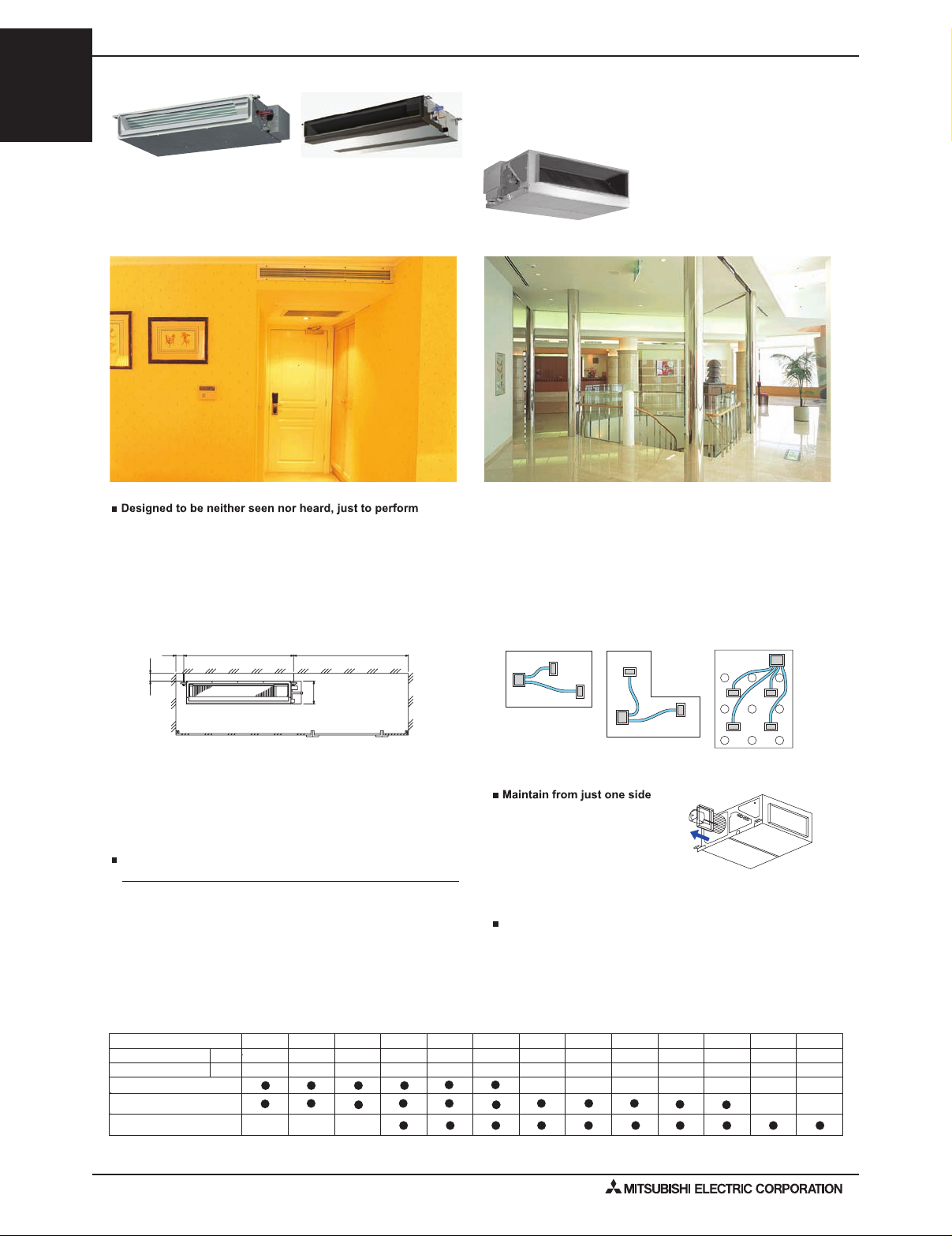
The PEFY models are high-performance, ceiling-concealed indoor units. In fact, if it weren’t for the constantly comfortable environment these units deliver, you
would not know they were there. The ducted fan coils are designed to be installed above the ceiling, hidden from public view, and they’re extremely quiet with
lowest sound of 22 dBA. The PEFY are extremely easy to access and maintain according to their application. They open on one side so you can easily access
the fan or motor for maintenance. They can be easily customized to your cooling and heating needs. The external static pressure settings are adjustable to
meet different application conditions such as the use of a high performance filter.
The additional external static pressure up to 0.8 in.WG
on PEFY-NMHU-E provides flexibility for duct extension,
branching, and air outlet configuration.
7-7/8" extremely thin body of PEFY-NMSU-E requires less ceiling space
Access door
Ceiling surface
Service space (viewed from the side)
600 mm [23-5/8 in] or more
100 mm
[3-15/16 in]
or more
10 mm
[13/32 in]
or more
200 [7-7/8]
Flexible design allows for elegant interior layout
PEFY-P-NMAU-E (Medium Static)
PEFY-P-NMHU-E (Alt. High Static)
PEFY-P-NMAU-E
PEFY-P-NMSU has a condensate lift of 21-11/16 in.,
and PEFY-P-NMAU has a condensate lift of 27-9/16 in.
PEFY-P-NMSU-E
PEFY-P-NMHU-E
P08 P12 P15 P18 P30 P36 P48P06 P24 P27 P54 P72 P96
Ceiling concealed
48,000
6,700
Nominal cooling cap.*1
Nominal heating cap.*2
6,000 8,000 12,000 15,000 18,000 24,000 27,000 30,000 36,000 54,000 72,000 96,000
60,000 80,000 108,00027,000 30,000 34,000 40,000 54,0009,000 13,500 17,000 20,000
BTU/h
BTU/h
* (Details are referred to in the specification sheet.)
* Refer to the Nominal conditions *1, *2 in the Specification sheet.
PEFY-P-NMAU-E
Sound Pressure Levels
CEILING-CONCEALED (LOW/MEDIUM/HIGH-STATIC PRESSURE)
PEFY-P-NMAU-E
PEFY-P-NMHU-E
PEFY-2
PEFY-P-NMSU-E/PEFY-P-NMAU-E/PEFY-P-NMHU-E (June 2010)
Page 3

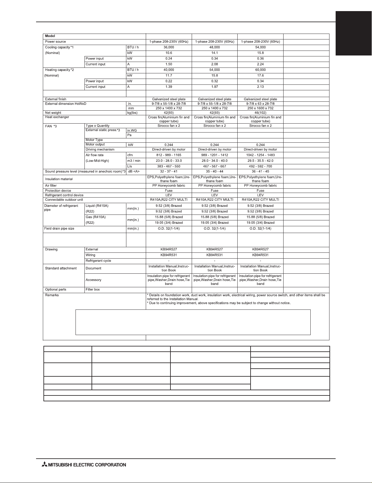
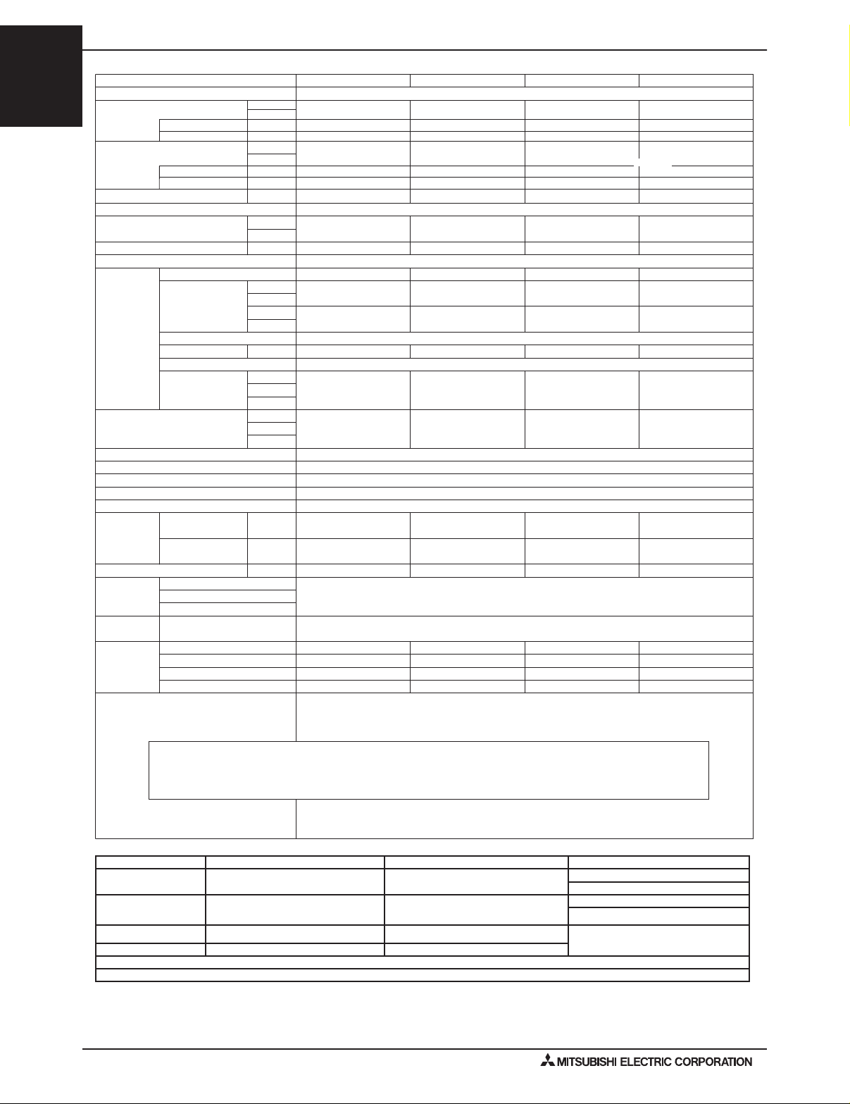
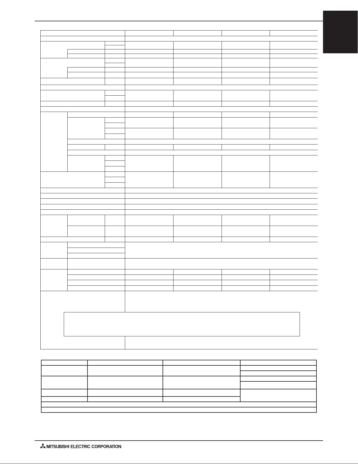
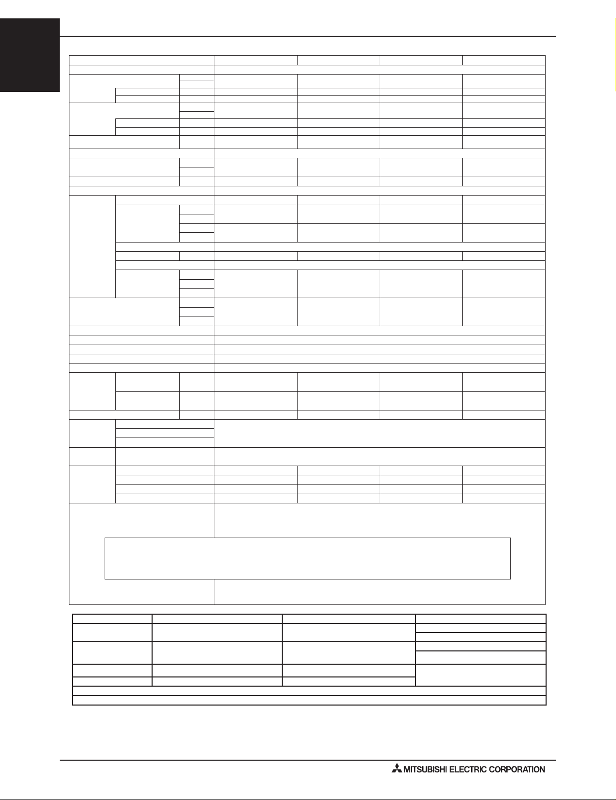
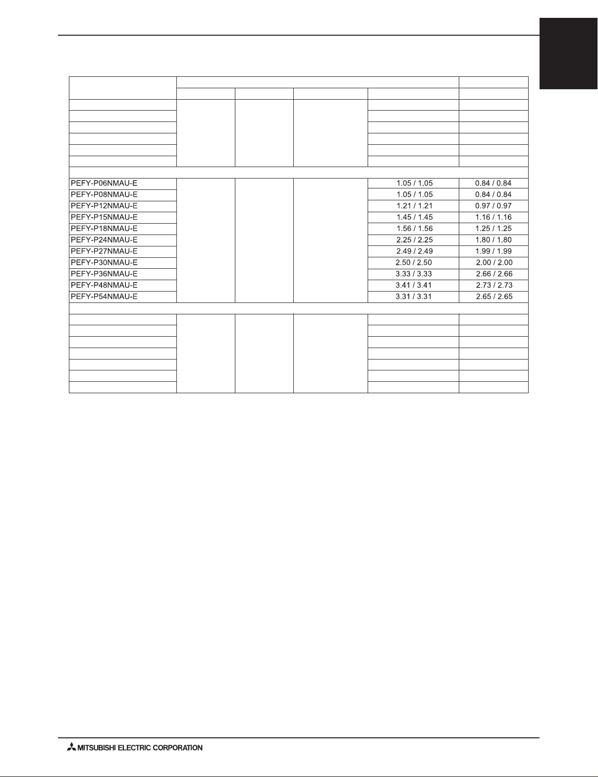
1. SPECIFICATIONS
Model PEFY-P06NMSU-E PEFY-P08NMSU-E PEFY-P12NMSU-E PEFY-P15NMSU-E
Power source 1-phase 208/230v 60Hz
Cooling capacity *1
(Nominal)
Heating capacity *2
(Nominal)
MCA A 0.47 / 0.50 0.47 / 0.50 0.68 / 0.74 1.20 / 1.33
External nish Galvanized
External dimension H x W x D
Net weight Lbs (kg) 42(19) 42(19) 46(20) 54(24)
Heat exchanger Cross n(aluminium n and copper tube)
Fan *4
Sound pressure level (Low-Mid-High)
(Measured in anechoic room) *4
Insulation material Polystyrene foam,polyethylene foam,urethane foam
Air lter PP honeycomb fabric (washable)
Protection Device Fuse
Refrigerant Control Device LEV
Connectable Outdoor Unit *3 R410A,R22 CITY MULTI R410A,R22 CITY MULTI R410A,R22 CITY MULTI
Diameter of
refrigerant pipe
(O.D.)
Diameter of drain pipe in. (mm) O.D. 1-1/4(32) O.D. 1-1/4(32) O.D. 1-1/4(32) O.D. 1-1/4(32)
Drain lift mechanism in. (mm) 21-11/16 (551) 21-11/16 (551) 21-11/16 (551) 21-11/16 (551)
Drawing
Standard
Attachment
Optional Parts External heater adaptor CN24RELAY-KIT-CM CN24RELAY-KIT-CM CN24RELAY-KIT-CM CN24RELAY-KIT-CM
Power input kW 0.05/0.05 0.06/0.06 0.07/0.07 0.07/0.07
Current input A 0.42/0.41 0.51/0.49 0.56/0.53 0.57/0.55
Power input kW 0.03/0.03 0.04/0.04 0.05/0.05 0.05/0.05
Current input A 0.32/0.31 0.41/0.39 0.46/0.43 0.47/0.45
Type x quantity Sirocco fan x 2 Sirocco fan x 2 Sirocco fan x 2 SIROCCO FAN X 3
External
Static pressure
Motor type DC brushless motor
Motor output kW 0.096 0.096 0.096 0.096
Driving mechanism Direct-driven
Airow rate
(Low-Mid-High)
Liquid (R410A)
(R22 )
Gas
(R410A)
(R22 )
External WKB94L522
Wiring WKB94L523
Refrigerant cycle Document Installation manual, instruction book
Accessory Drain hose (exible joint)
Btu / h 6,000 8,000 12,000 15,000
kW 1.8 2.3 3.5 4.4
Btu / h 6,700 9,000 13,500 17,000
kW 2.0 2.6 4.0 5.0
in. 7-7/8 X 31-1/8 X 27-9/16 7-7/8 X 31-1/8 X 27-9/16 7-7/8 X 31-1/8 X 27-9/16 7-7/8 X 39 X 27-9/16
mm 200 X 790 X 700 200 X 790 X 700 200 X 790 X 700 200 X 990 X 700
in.WG
PA 5-(15*)-35-50 5-(15*)-35-50 5-(15*)-35-50 5-(15*)-35-50
in.WG
PA 5-(15*)-35-50 5-(15*)-35-50 5-(15*)-35-50 5-(15*)-35-50
cfm
3
m
L / s 83-100-117 91-116-150 100-133-175 133-158-183
dB <A> 22-24-28 (208V) 23-26-30 (208V) 23-28-35 (208V) 28-30-33 (208V)
dB<A> 22-24-28 (230V) 23-26-30 (230V) 23-28-35 (230V) 28-30-33 (230V)
dB <A> - - - -
in. (mm)
in. (mm)
0.02-(0.06*)-0.14-0.20
(208V)
0.02-(0.06*)-0.14-0.20
(230V)
/ min. 5-6-7 5.5-7-9 6-8-10.5 8-9.5-11
176-212-247 194-247-317 211-282-370 282-335-388
1/4 (6.35) Brazed 1/4 (6.35) Brazed 1/4 (6.35) Brazed 1/4 (6.35) Brazed
1/4 (6.35) Brazed 1/4 (6.35) Brazed 1/4 (6.35) Brazed 1/4 (6.35) Brazed
1/2 (12.7) Brazed 1/2 (12.7) Brazed 1/2 (12.7) Brazed 1/2 (12.7) Brazed
1/2 (12.7) Brazed 1/2 (12.7) Brazed 1/2 (12.7) Brazed 1/2 (12.7) Brazed
0.02-(0.06*)-0.14-0.20
(208V)
0.02-(0.06*)-0.14-0.20
(230V)
0.02-(0.06*)-0.14-0.20
(208V)
0.02-(0.06*)-0.14-
0.20(230V)
0.02-(0.06*)-0.14-0.20
(208V)
0.02-(0.06*)-0.14-
0.20(230V)
PEFY-P-NMHU-E
PEFY-P-NMSU-E
PEFY-P-NMAU-E
Ventilation Air: Providing sufcient ventilation air is an important part of every building design.
ASHRAE standard 62 provides the minimum ventilation air requirements. Also check local
Remark
Note: *1 Nominal cooling conditions *2 Nominal heating conditions Unit converter
Indoor:
Outdoor: 95degF D.B. (35degC D.B.)
Pipe length: 25 ft. (7.6 m) 25 ft. (7.6 m)
Level difference: 0 ft. (0 m) 0 ft. (0 m)
*3 PUHY-THMU,PURY-THMU,PUHY-YHMU,PURY-YHMU,PQHY, PQRY, PUHY-HP, PUMY-NHMU, PUHY-T/YHMU, PURY-T/YHMU
*4 The external static pressure is set to 15 Pa (0.06 in. WG) at factory shipment.
*Due to continuing improvement, above specication may be subject to change without notice.
codes.
Installation
Details on foundation work, duct work, insulation work, electrical wiring, power source switch, and other items shall be
referred to the Installation Manual.
80degF D.B. / 67degF W.B.
(26.7degC D.B. / 19.4degC W.B.)
70degF D.B. (21.1degC D.B.)
47degF D.B. / 43degF W.B.
(8.3degC D.B. / 6.1degC W.B.)
kcal/h = kW x 860
BTU/h = kW x 3,412
cfm = m3/min x 35.31
lbs = kg / 0.4536
*Above specication data is
subject to rounding variation.
PEFY-3PEFY-P-NMSU-E/PEFY-P-NMAU-E/PEFY-P-NMHU-E (June 2010)
Page 4
PEFY-P-NMSU-E
1. SPECIFICATIONS
Model PEFY-P18NMSU-E PEFY-P24NMSU-E
Power source 1-phase 208/230V 60Hz
Cooling capacity *1
(Nominal)
PEFY-P-NMAU-E
PEFY-P-NMHU-E
Heating capacity *2
(Nominal)
MCA A 1.20 / 1.33 1.57 / 1.73
External nish Galvanized
External dimension H x W x D
Net weight Lbs (kg) 54(24) 62(28)
Heat exchanger Cross n(Aluminium n and copper tube)
Fan *3
Sound pressure level (Low-Mid-High)
(Measured in anechoic room) *3
Insulation material Polystyrene foam,Polyethylene foam,Urethane foam
Air lter PP Honeycomb fabric (washable)
Protection Device Fuse
Refrigerant Control Device LEV
Connectable Outdoor Unit R410A,R22 CITY MULTI R410A,R22 CITY MULTI
Diameter of
refrigerant pipe
(O.D.)
Diameter of drain pipe in. (mm) O.D. 1-1/4(32) O.D. 1-1/4(32)
Drain lift mechanism in. (mm) 21-11/16 (551) 21-11/16 (551)
Drawing
Standard
Attachment
Optional Parts External heater adaptor CN24RELAY-KIT-CM CN24RELAY-KIT-CM
Remark Details on foundation work, duct work, insulation work, electrical wiring, power source switch, and other
Power input kW 0.09/0.09 0.12/0.12
Current input A 0.74/0.70 0.98/0.93
Power input kW 0.07/0.07 0.10/0.10
Current input A
Type x quantity Sirocco fan x 3 Sirocco fan x 4
External
Static pressure
Motor type DC brushless motor
Motor output kW 0.096 0.096
Driving mechanism Direct-driven
Airow rate
(Low-Mid-High)
Liquid (R410A)
(R22 )
Gas
(R410A)
(R22 )
External WKB94L522
Wiring WKB94L523
Refrigerant cycle Document Installation Manual, Instruction Book
Accessory Drain hose (exible joint)
Btu / h 18,000 24,000
kW 5.3 7.0
Btu / h 20,000 27,000
kW 5.9 7.9
0.64/0.60 0.88/0.83
in. 7-7/8 x 39 x 27-9/16 7-7/8 x 46-7/8 x 27-9/16
mm 200 x 990 x 700 200 x 1190 x 700
in.WG 0.02-(0.06*)-0.14-0.20 (208V) 0.02-(0.06*)-0.14-0.20(208V)
PA 5-(15*)-35-50 5-(15*)-35-50
in.WG 0.02-(0.06*)-0.14-0.20 (230V) 0.02-(0.06*)-0.14-0.20(230V)
PA 5-(15*)-35-50 5-(15*)-35-50
cfm 353-441-529 423-565-706
3
/ min. 10-12.5-15 12-16-20
m
L / s 167-208-250 200-267-333
dB <A> 30-34-37 (208V) 30-35-40 (208V)
dB<A> 30-34-37 (230V) 30-35-40 (230V)
dB <A> - -
in. (mm)
in. (mm)
items shall be referred to the Installation Manual.
1/4 (6.35) Brazed 3/8 (9.52) Brazed
3/8 (9.52) Brazed 3/8 (9.52) Brazed
1/2 (12.7) Brazed 5/8 (15.88) Brazed
5/8 (15.88) Brazed 5/8 (15.88) Brazed
Ventilation Air: Providing sufcient ventilation air is an important part of every building design.
ASHRAE standard 62 provides the minimum ventilation air requirements. Also check local
codes.
Note: *1 Nominal cooling conditions *2 Nominal heating conditions Unit converter
Indoor:
Outdoor: 95degF D.B. (35degC D.B.)
Pipe length: 25 ft. (7.6 m) 25 ft. (7.6 m)
Level difference: 0 ft. (0 m) 0 ft. (0 m)
*3 The external static pressure is set to 15 Pa (0.06 in. WG) at factory shipment.
*Due to continuing improvement, above specication may be subject to change without notice.
PEFY-4
PEFY-P-NMSU-E/PEFY-P-NMAU-E/PEFY-P-NMHU-E (June 2010)
80degF D.B. / 67degF W.B.
(26.7degC D.B. / 19.4degC W.B.)
70degF D.B. (21.1degC D.B.)
47degF D.B. / 43degF W.B.
(8.3degC D.B. / 6.1degC W.B.)
kcal/h = kW x 860
BTU/h = kW x 3,412
cfm = m3/min x 35.31
lbs = kg / 0.4536
*Above specication data is
subject to rounding variation.
Page 5
1. SPECIFICATIONS
PEFY-P-NMHU-E
PEFY-P-NMSU-E
PEFY-P-NMAU-E
MCA
PEFY-P06NMAU-E PEFY-P08NMAU-E
A
0.14-(0.20*)-0.28-0.40-0.60
1.05
35-(50*)-70-100-150 35-(50*)-70-100-150
DC brushless motor
1.05 1.21
0.14-(0.20*)-0.28-0.40-0.60 0.14-(0.20*)-0.28-0.40-0.60 0.14-(0.20*)-0.28-0.40-0.60
DC brushless motor DC brushless motor
PEFY-P12NMAU-E
35-(50*)-70-100-150 35-(50*)-70-100-150
PEFY-P15NMAU-E
1.45
DC brushless motor
Drain Lift Mechanism
External Heater Adapter
27-9/16 27-9/16 27-9/16 27-9/16
CN24RELAY-KIT-CM3
CN24RELAY-KIT-CM3
CN24RELAY-KIT-CM3
CN24RELAY-KIT-CM3
Ventilation Air: Providing sufcient ventilation air is an important part of every building design.
ASHRAE standard 62 provides the minimum ventilation air requirements. Also check local
codes.
Note: *1 Nominal cooling conditions *2 Nominal heating conditions Unit converter
Indoor:
Outdoor: 95degF D.B. (35degC D.B.)
Pipe length: 25 ft. (7.6 m) 25 ft. (7.6 m)
Level difference: 0 ft. (0 m) 0 ft. (0 m)
*3 The rated external static pressure is set to 50 Pa (0.20 in. WG) at factory shipment.
*Due to continuing improvement, above specication may be subject to change without notice.
80degF D.B. / 67degF W.B.
(26.7degC D.B. / 19.4degC W.B.)
70degF D.B. (21.1degC D.B.)
47degF D.B. / 43degF W.B.
(8.3degC D.B. / 6.1degC W.B.)
kcal/h = kW x 860
BTU/h = kW x 3,412
cfm = m3/min x 35.31
lbs = kg / 0.4536
*Above specication data is
subject to rounding variation.
PEFY-5PEFY-P-NMSU-E/PEFY-P-NMAU-E/PEFY-P-NMHU-E (June 2010)
Page 6
1. SPECIFICATIONS
PEFY-P-NMSU-E
PEFY-P-NMAU-E
PEFY-P-NMHU-E
MCA
PEFY-P18NMAU-E PEFY-P24NMAU-E
A
1.56
0.14-(0.20*)-0.28-0.40-0.60
35-(50*)-70-100-150
DC brushless motor
2.25
0.14-(0.20*)-0.28-0.40-0.60
35-(50*)-70-100-150
DC brushless motor
PEFY-P27NMAU-E
2.49
0.14-(0.20*)-0.28-0.40-0.60
35-(50*)-70-100-150
DC brushless motor
PEFY-P30NMAU-E
2.50
0.14-(0.20*)-0.28-0.40-0.60
35-(50*)-70-100-150
DC brushless motor
Drain Lift Mechanism
External Heater Adapter
27-9/16
CN24RELAY-KIT-CM3
27-9/16 27-9/16 27-9/16
CN24RELAY-KIT-CM3
CN24RELAY-KIT-CM3
CN24RELAY-KIT-CM3
Ventilation Air: Providing sufcient ventilation air is an important part of every building design.
ASHRAE standard 62 provides the minimum ventilation air requirements. Also check local
codes.
Note: *1 Nominal cooling conditions *2 Nominal heating conditions Unit converter
Indoor:
Outdoor: 95degF D.B. (35degC D.B.)
Pipe length: 25 ft. (7.6 m) 25 ft. (7.6 m)
Level difference: 0 ft. (0 m) 0 ft. (0 m)
*3 The rated external static pressure is set to 50 Pa (0.20 in. WG) at factory shipment.
*Due to continuing improvement, above specication may be subject to change without notice.
80degF D.B. / 67degF W.B.
(26.7degC D.B. / 19.4degC W.B.)
70degF D.B. (21.1degC D.B.)
47degF D.B. / 43degF W.B.
(8.3degC D.B. / 6.1degC W.B.)
kcal/h = kW x 860
BTU/h = kW x 3,412
cfm = m3/min x 35.31
lbs = kg / 0.4536
*Above specication data is
subject to rounding variation.
PEFY-6
PEFY-P-NMSU-E/PEFY-P-NMAU-E/PEFY-P-NMHU-E (June 2010)
Page 7
1. SPECIFICATIONS
PEFY-P-NMHU-E
PEFY-P-NMSU-E
PEFY-P-NMAU-E
MCA
PEFY-P36NMAU-E
A
3.33 3.41
0.14-(0.20*)-0.28-0.40-0.60
35-(50*)-70-100-150
DC brushless motor
PEFY-P48NMAU-E
0.14-(0.20*)-0.28-0.40-0.60
35-(50*)-70-100-150 35-(50*)-70-100-150
DC brushless motor
PEFY-P54NMAU-E
3.31
0.14-(0.20*)-0.28-0.40-0.60
DC brushless motor
Drain Lift Mechanism in.
27-9/16
CN24RELAY-KIT-CM3
27-9/16
CN24RELAY-KIT-CM3 CN24RELAY-KIT-CM3
27-9/16
Ventilation Air: Providing sufcient ventilation air is an important part of every building design.
ASHRAE standard 62 provides the minimum ventilation air requirements. Also check local
codes.
Note: *1 Nominal cooling conditions *2 Nominal heating conditions Unit converter
Indoor:
Outdoor: 95degF D.B. (35degC D.B.)
Pipe length: 25 ft. (7.6 m) 25 ft. (7.6 m)
Level difference: 0 ft. (0 m) 0 ft. (0 m)
*3 The rated external static pressure is set to 50 Pa (0.20 in. WG) at factory shipment.
*Due to continuing improvement, above specication may be subject to change without notice.
80degF D.B. / 67degF W.B.
(26.7degC D.B. / 19.4degC W.B.)
70degF D.B. (21.1degC D.B.)
47degF D.B. / 43degF W.B.
(8.3degC D.B. / 6.1degC W.B.)
kcal/h = kW x 860
BTU/h = kW x 3,412
cfm = m3/min x 35.31
lbs = kg / 0.4536
*Above specication data is
subject to rounding variation.
PEFY-7PEFY-P-NMSU-E/PEFY-P-NMAU-E/PEFY-P-NMHU-E (June 2010)
Page 8
PEFY-P-NMSU-E
07
81
98
81
1. SPECIFICATIONS
ModelPEFY-P15NMHU-EPEFY-P18NMHU-E PEFY-P24NMHU-E PEFY-P27NMHU-E
Power source 1-phase 208/230 V 60Hz
Cooling capacity BTU / h 15,000 18,000 24,000 27,000
(Nominal)
PEFY-P-NMAU-E
PEFY-P-NMHU-E
Heating capacity *2 BTU / h
(Nominal) kW 5.05.9 7.
MCA
External finish Galvanized
External dimension H x W x Din. 14-31/32 x 29-17/32 x 35-7/1614-31/32 x 29-17/32 x 35-7/1614-31/32 x 29-17/32 x 35-7/1614-31/32 x 39-3/8 x 35-7/16
Net weight lbs (kg) 98 (44) 100 (45) 100 (45) 111 (50)
Heat exchanger Cross fin(Aluminium fin and copper tube)
FANType x Quantity Sirocco fan x 1Sirocco fan x 1Sirocco fan x 1Sirocco fan x 1
Sound pressure level (Low-High) dB <A>25-32 (208V) 25-32 (208V) 29-36 (208V) 30-38 (208V)
(measured in anechoic room) dB <A>34-39 (230V) 34-39 (230V) 36-41 (230V) 35-41 (230V)
Insulation material Polystyrene foam,Polyethylene foam,Urethane foam
Air filter Field-supplied; see Optional Parts
Protection device Fuse
Refrigerant control device LEV
Connectable outdoor unit R410A,R22 CITY MULTI
Diameter of Liquid(R410A)
refrigerant pipe (R22 )1/4 (6.35) Flare 3/8 (9.52) Flare3/8 (9.52) Flare3/8 (9.52) Flare
(O.D.) Gas (R410A)
Field drain pipe size in. (mm) O.D. 1-1/4 (32) O.D. 1-1/4 (32) O.D. 1-1/4 (32) O.D. 1-1/4 (32)
DrawingExternal W277664
Standard Document Installation Manual,Installation Book
attachment Accessory Drain hose I.D. 1-1/4inch (32mm)(flexible joint)
Optional partsDrain pump PAC-KE04DM-F PAC-KE04DM-F PAC-KE04DM-F PAC-KE04DM-F
Remarks *Details on foundation work, duct work, insulation work, electrical wiring, power source switch, and other items shall be referred to the
*1
Power input kW 0.188/0.207 0.188/0.207 0.245/0.270 0.270/0.297
Current inpu
Power input kW
Current inputA
*3
Externalstatic
pressure
Motor type 1-phase induction motor
Motor output kW 0.130 0.1300.180 0.220
Driving mechanism Direct-driven
Airflow rate cfm353-494 353-494477-671 547-777
(Low-High) m3 / min10.0-14.0 10.0-14.013.5-19.0 15.5-22.0
Wiring W660134
Refrigerant cycle -
External heater adaptor CN24RELAY-KIT-CM3
Filter box PAC-KE63TB-F PAC-KE63TB-F PAC-KE63TB-F PAC-KE80TB-F
Long life filter PAC-KE86LAF PAC-KE86LAF PAC-KE86LAF PAC-KE88LAF
kW 4.45.3
tA
A
mm 380 x 750 x 900380 x 750 x 900380 x 750 x 900380 x 1,000 x 900
(208V)in.WG
Pa
(230V) in.WG
Pa
L / s167-233 167-233225-317 258-367
*3
dB <A> ----
in. (mm)
in. (mm)
(R22 )1/2 (12.7) Flare 5/8 (15.88) Flare 5/8 (15.88) Flare 5/8 (15.88) Flare
0.96/1.060.96/1.061.25/1.3
17,000 20,000 27,000 30,000
0.188/0.207 0.188/0.207 0.245/0.270 0.270/0.297
0.96/1.060.96/1.061.25/1.3
1.20 / 1.331.20 / 1.331.57 / 1.731.72 / 1.89
(0.201*)-0.642 (208V)
(50*)-160 (50*)-160
0.401-(0.602*)-0.803 (230V)
100-(150*)-200
1/4 (6.35) Flare 1/4 (6.35) Flare3/8 (9.52) Flare3/8 (9.52) Flare
1/2 (12.7) Flare 1/2 (12.7) Flare5/8 (15.88) Flare5/8 (15.88) Flare
Installation Manual.
*Due to continuing improvement, above specification may be subject to change without notice.
(0.201*)-0.642 (208V)(0.201*)-0.642 (208V)(0.201*)-0.642 (208V)
0.401-(0.602*)-0.803 (230V)
100-(150*)-200 100-(150*)-200
CN24RELAY-KIT-CM3
CN24RELAY-KIT-CM3
7.
(50*)-160 (50*)-160
0.401-(0.602*)-0.803 (230V)
0.401-(0.602*)-0.803 (230V)
100-(150*)-200
CN24RELAY-KIT-CM3
.9
.37/1.51
.8
.37/1.51
Ventilation Air: Providing sufcient ventilation air is an important part of every building design.
ASHRAE standard 62 provides the minimum ventilation air requirements. Also check local codes.
Note: *1 Nominal cooling conditions *2 Nominal heating conditions Unit converter
Indoor:
Outdoor: 95degF D.B. (35degC D.B.)
80degF D.B. / 67degF W.B.
(26.7degC D.B. / 19.4degC W.B.)
70degF D.B. (21.1degC D.B.)
47degF D.B. / 43degF W.B.
(8.3degC D.B. / 6.1degC W.B.)
Pipe length: 25 ft. (7.6 m) 25 ft. (7.6 m)
Level difference: 0 ft. (0 m) 0 ft. (0 m)
*3 The rated external static pressure is set to 50 Pa (0.20 in. WG) for 208V and 150 Pa (0.60) for 230V at factory shipment.
*Due to continuing improvement, above specication may be subject to change without notice.
PEFY-8
PEFY-P-NMSU-E/PEFY-P-NMAU-E/PEFY-P-NMHU-E (June 2010)
kcal/h = kW x 860
BTU/h = kW x 3,412
cfm = m3/min x 35.31
lbs = kg / 0.4536
*Above specication data is
subject to rounding variation.
Page 9
1. SPECIFICATIONS
40
40
00
02
----
74
Model PEFY-P30NMHU-E PEFY-P36NMHU-E PEFY-P48NMHU-E PEFY-P54NMHU-E
Power source 1-phase 208/230 V 60Hz
Cooling capacityBTU / h 30,000 36,000 48,000 54,000
(Nominal)
Heating capacity *2 BTU / h
(Nominal)
MCA 2.08 / 2.29 4.23 / 4.674.23 / 4.6
External finish Galvanized
External dimension H x W x Din. 14-31/32 x 39-3/8 x 35-7/1614-31/32 x 47-1/4 x 35-7/1614-31/32 x 47-1/4 x 35-7/1614-31/32 x 47-1/4 x 35-7/16
Net weight lbs (kg) 111 (50) 155 (70) 155 (70) 155 (70)
Heat exchanger Cross fin(Aluminium fin and copper tube)
FAN Type x Quantity Sirocco fan x 1Sirocco fan x 2Sirocco fan x 2Sirocco fan x 2
Sound pressure level (Low-High) dB <A>33-40 (208V)31-41 (208V) 31-41 (208V)31-41 (208V)
(measured in anechoic room) dB <A>38-43 (230V)38-44 (230V) 38-44 (230V) 38-44 (230V)
Insulation material Polystyrene foam,Polyethylene foam,Urethane foam
Air filter Field-supplied; see Optional Parts
Protection device Fuse
Refrigerant control device LEV
Connectable outdoor unit R410A,R22 CITY MULTI
Diameter of Liquid(R410A)
refrigerant pipe (R22 )3/8 (9.52) Flare3/8 (9.52) Flare3/8 (9.52) Flare3/8 (9.52) Flare
(O.D.) Gas(R410A)
Field drain pipe size in. (mm) O.D. 1-1/4 (32) O.D. 1-1/4 (32) O.D. 1-1/4 (32) O.D. 1-1/4 (32)
Drawing External W277664
Standard Document Installation Manual,Installation Book
attachment Accessory Drain hose I.D. 1-1/4inch (32mm)(flexible joint)
Optional parts Drain pump PAC-KE04DM-F PAC-KE04DM-F PAC-KE04DM-F PAC-KE04DM-F
Remarks *Details on foundation work, duct work, insulation work, electrical wiring, power source switch, and other items shall be referred to the
*1
Power input kW 0.326/0.3600.683/0.7540.683/0.75
Current input A 1.66/1.83 3.38/3.73 3.38/3.73 3.43/3.78
Power input kW
Current input
A
*3
External
static
pressure
Motor type 1-phase induction motor
Motor output kW 0.2300.400 0.40
Driving mechanism Direct-driven
Airflow rate cfm 636-883 936-1,342936-1,342 989-1,412
(Low-High) m3 / min18.0-25.0 26.5-38.0 26.5-38.
Wiring W660134
Refrigerant cycle -
External heater adaptor
Filter box PAC-KE80TB-F PAC-KE140TB-F PAC-KE140TB-F PAC-KE140TB-F
Long life filter PAC-KE88LAF PAC-KE89LAF PAC-KE89LAF PAC-KE89LAF
W
k
kW
A
mm 380 x 1,000 x 900 380 x 1,200 x 900 380 x 1,200 x 900380 x 1,200 x 900
(208V) in.WG
Pa
(230V) in.WG
Pa
L / s 300-417 442-633 442-633 467-667
*3
dB <A>
in. (mm)
in. (mm)
(R22 )5/8 (15.88) Flare3/4 (19.05) Flare3/4 (19.05) Flare 3/4 (19.05) Flare
0.401-(0.602*)-0.803 (230V)
CN24RELAY-KIT-CM3
Installation Manual.
*Due to continuing improvement, above specification may be subject to change without notice.
8.8 10.6 14.1 15.8
34,000 40,000 54,000 60,000
10.0 11.7 15.8 17.6
0.326/0.3600.683/0.7540.683/0.75
1.66/1.83 3.38/3.73 3.38/3.73 3.43/3.78
(0.201*)-0.642 (208V)
(50*)-160
100-(150*)-200
3/8 (9.52) Flare 3/8 (9.52) Flare 3/8 (9.52) Flare 3/8 (9.52) Flare
5/8 (15.88) Flare5/8 (15.88) Flare5/8 (15.88) Flare 5/8 (15.88) Flare
(0.201*)-0.642 (208V)
(50*)-160
0.401-(0.602*)-0.803 (230V)
100-(150*)-200
CN24RELAY-KIT-CM3
(0.201*)-0.642 (208V)
(50*)-160
0.401-(0.602*)-0.803 (230V)
100-(150*)-200
CN24RELAY-KIT-CM3 CN24RELAY-KIT-CM3
(0.201*)-0.642 (208V)
0.401-(0.602*)-0.803 (230V)
100-(150*)-200
.695/0.767
.695/0.767
.29 / 4.73
(50*)-160
.400
8.0-40.0
PEFY-P-NMHU-E
PEFY-P-NMSU-E
PEFY-P-NMAU-E
Ventilation Air: Providing sufcient ventilation air is an important part of every building design.
ASHRAE standard 62 provides the minimum ventilation air requirements. Also check local codes.
Note: *1 Nominal cooling conditions *2 Nominal heating conditions Unit converter
Indoor:
Outdoor: 95degF D.B. (35degC D.B.)
80degF D.B. / 67degF W.B.
(26.7degC D.B. / 19.4degC W.B.)
70degF D.B. (21.1degC D.B.)
47degF D.B. / 43degF W.B.
(8.3degC D.B. / 6.1degC W.B.)
Pipe length: 25 ft. (7.6 m) 25 ft. (7.6 m)
Level difference: 0 ft. (0 m) 0 ft. (0 m)
*3 The rated external static pressure is set to 50 Pa (0.20 in. WG) for 208V and 150 Pa (0.60) for 230V at factory shipment.
*Due to continuing improvement, above specication may be subject to change without notice.
kcal/h = kW x 860
BTU/h = kW x 3,412
cfm = m3/min x 35.31
lbs = kg / 0.4536
*Above specication data is
subject to rounding variation.
PEFY-9PEFY-P-NMSU-E/PEFY-P-NMAU-E/PEFY-P-NMHU-E (June 2010)
Page 10
PEFY-P-NMSU-E
1. SPECIFICATIONS
Model PEFY-P72NMHU-E PEFY-P96NMHU-E
Power source 3-phase 208/230 V 60Hz
Cooling capacity BTU / h 72,000 96,000
PEFY-P-NMAU-E
PEFY-P-NMHU-E
(Nominal)
Heating capacity
(Nominal)
MCA 5.60 / 6.187.12 / 7.85
External finish Galvanized
External dimension H x W x Din. 18-17/32 x 49-7/32 x 44-1/8 18-17/32 x 49-7/32 x 44-1/8
Net weightlbs (kg) 221 (100) 221 (100)
Heat exchanger Cross fin(Aluminium fin and copper tube)
FANType x Quantity Sirocco fan x 2Sirocco fan x 2
Sound pressure leveldB <A>45 (208V)52 (208V)
(measured in anechoic room) dB <A>47 (230V) 54 (230V)
Insulation material Polystyrene foam,Polyethylene foam,Urethane foam
Air filter Field-supplied; see Optional Parts
Protection device Fuse
Refrigerant control device LEV
Connectable outdoor unit R410A,R22 CITY MULTI
Diameter of Liquid(R410A)
refrigerant pipe (R22) 1/2 (12.7) Brazed 1/2 (12.7) Brazed
(O.D.) Gas (R410A)
Field drain pipe size in. (mm) O.D. 1-1/4 (32) O.D. 1-1/4 (32)
DrawingExternal W277665
Standard Document Installation Manual,Installation Book
attachment Accessory Drain hose I.D. 1-1/4inch (32mm)(flexible joint)
Optional partsDrain pump PAC-KE04DM-F PAC-KE04DM-F
Remarks *Details on foundation work, duct work, insulation work, electrical wiring, power source switch, and other items shall be referred to the
*1
Power inputkW 1.352/1.495 1.690/1.870
Current inputA 4.48/4.945.69/6.28
*2
Power inputkW
Current inputA
*3
Externalstatic
pressure
Motor type 3-phase induction motor
Motor output kW 0.650 0.850
Driving mechanism Direct-driven
Airflow rate cfm2,048 2,541
Wiring W660130
Refrigerant cycle -
External heater adaptor CN24RELAY-KIT-CM3
Filter box PAC-KE250TB-F PAC-KE250TB-F
Long life filter PAC-KE85LAF PAC-KE85LAF
kW
BTU / h
kW 23.4 31.7
A
mm 470 x 1,250 x 1,120 470 x 1,250 x 1,120
(208V) in.WG
Pa
(230V) in.WG
Pa
m3 / min58.072.0
L / s967 1,200
*3
dB <A>- -
in. (mm)
in. (mm)
(R22 )1 (25.4) Brazed1-1/8 (28.58) Brazed
CN24RELAY-KIT-CM3
Installation Manual.
*Due to continuing improvement, above specification may be subject to change without notice.
21.1 28.1
80,000 108,000
1.352/1.495 1.690/1.870
4.48/4.945.69/6.28
0.281-(0.642*) (208V)
70-(160*)
0.401-(0.803*) (230V)
100-(200*)
3/8 (9.52) Brazed 3/8 (9.52) Brazed
3/4 (19.05) Brazed 7/8 (22.2) Brazed
0.281-(0.642*) (208V)
70-(160*)
0.401-(0.803*) (230V)
100-(200*)
Ventilation Air: Providing sufcient ventilation air is an important part of every building design.
ASHRAE standard 62 provides the minimum ventilation air requirements. Also check local codes.
Note: *1 Nominal cooling conditions *2 Nominal heating conditions Unit converter
Indoor:
Outdoor: 95degF D.B. (35degC D.B.)
80degF D.B. / 67degF W.B.
(26.7degC D.B. / 19.4degC W.B.)
70degF D.B. (21.1degC D.B.)
47degF D.B. / 43degF W.B.
(8.3degC D.B. / 6.1degC W.B.)
Pipe length: 25 ft. (7.6 m) 25 ft. (7.6 m)
Level difference: 0 ft. (0 m) 0 ft. (0 m)
*3 The rated external static pressure is set to 160 Pa (0.642 in. WG) for 208V and 200 Pa (0.803) for 230V at factory shipment.
*Due to continuing improvement, above specication may be subject to change without notice.
PEFY-10
PEFY-P-NMSU-E/PEFY-P-NMAU-E/PEFY-P-NMHU-E (June 2010)
kcal/h = kW x 860
BTU/h = kW x 3,412
cfm = m3/min x 35.31
lbs = kg / 0.4536
*Above specication data is
subject to rounding variation.
Page 11
1. SPECIFICATIONS
S
Electrical characteristics of Indoor unit
Symbols: MCA : Min.Circuit Amps (=1.25xFLA) FLA : Full Load Amps
tI
)F
IFM :Indoor Fan Motor
Model
PEFY-P06NMSU-E 0.47 / 0.50 0.32 / 0.31
PEFY-P08NMSU-E 0.47 / 0.50 0.41 / 0.39
PEFY-P12NMSU-E 0.68 / 0.74 0.46 / 0.43
PEFY-P15NMSU-E 1.20 / 1.33 0.47 / 0.45
PEFY-P18NMSU-E 1.20 / 1.33 0.64 / 0.60
PEFY-P24NMSU-E 1.57 / 1.73 0.88 / 0.83
Hz VoltsVoltage rangeMCA(A
60Hz
Indoor Uni
208 / 230V
188 to 253V
FM
LA(A)
PEFY-P-NMHU-E
PEFY-P-NMSU-E
PEFY-P-NMAU-E
PEFY-P27NMHU-E 1.72 / 1.89 1.37 / 1.51
PEFY-P30NMHU-E 2.08 / 2.29 1.66 / 1.83
PEFY-P36NMHU-E 4.23 / 4.67 3.38 / 3.73
PEFY-P48NMHU-E 4.23 / 4.67 3.38 / 3.73
PEFY-P54NMHU-E 4.29 / 4.73 3.43 / 3.78
PEFY-P72NMHU-E 5.60 / 6.18 4.48 / 4.94
PEFY-P96NMHU-E 7.12 / 7.85 5.69 / 6.28
60Hz 208 / 230 198 to 253V
60Hz 208 / 230 188 to 253V
V
V
PEFY-11PEFY-P-NMSU-E/PEFY-P-NMAU-E/PEFY-P-NMHU-E (June 2010)
Page 12
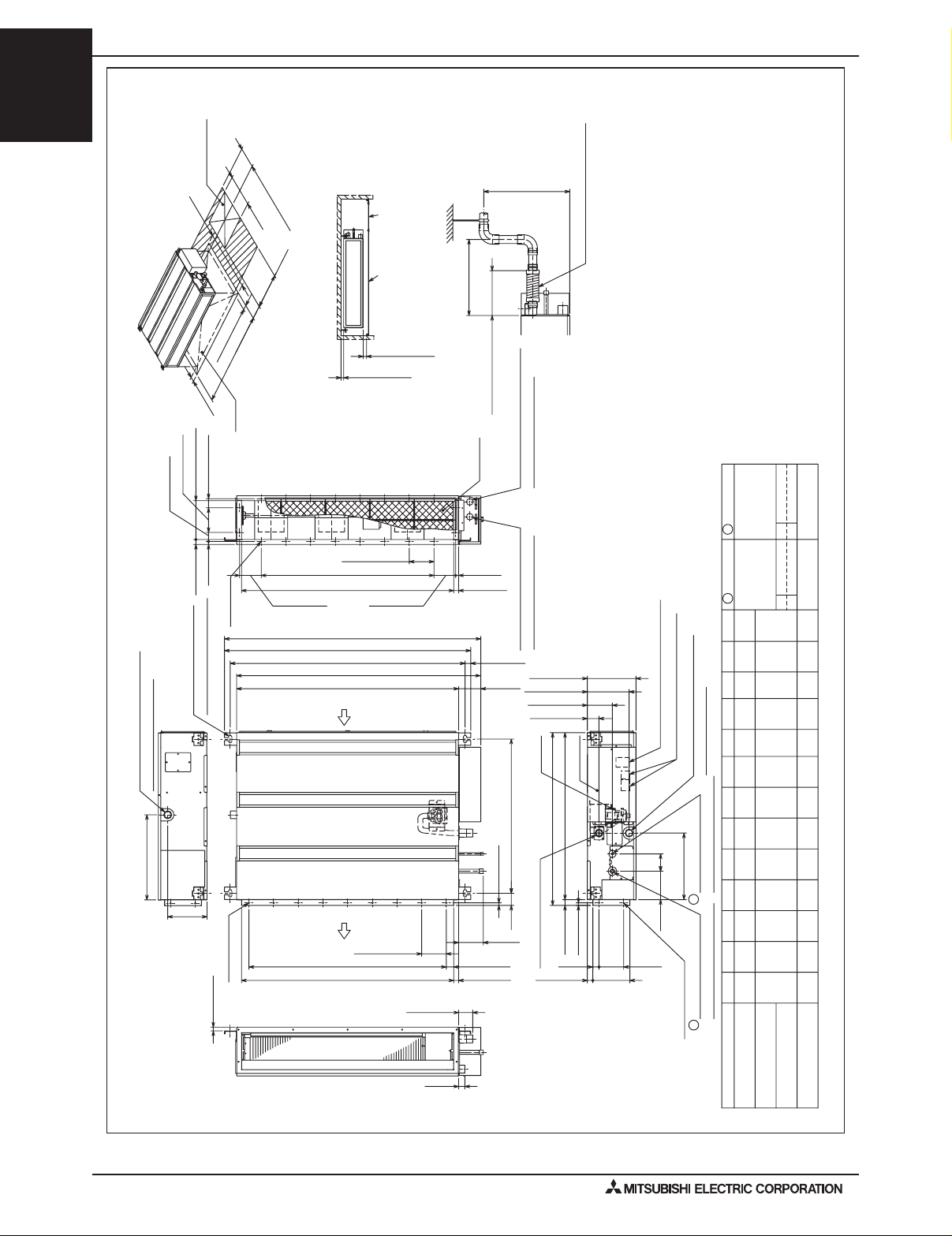
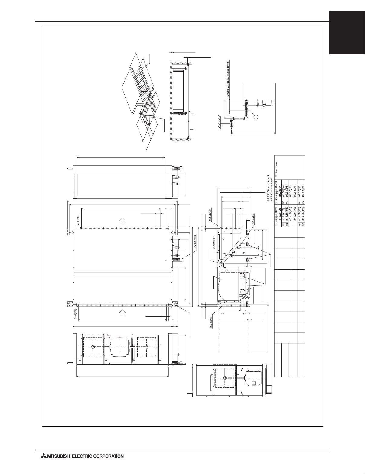
2. EXTERNAL DIMENSIONS
PEFY-P-NMSU-E
PEFY-P06,08,12,15,18,24NMSU-E
PEFY-P-NMAU-E
PEFY-P-NMHU-E
Access door
(11-13/16)
450
More than 300
(17-23/32)
450
(17-23/32)
50~150
(1-31/32~5-29/32)
100(3-15/16)
37(1-15/32)
777
(30-19/32)
50(1-31/32)
37(1-15/32)
157.5 (6-7/32)20(13/16)
50(1-31/32)
G
Note2
Access door
(11-13/16)
Ceiling surface
Required space for service and maintenance
Make the access door at the appointed
(13/16)
(13/32)
More than 10
Less than 300
position properly for service maintenance.
More than 20
±5(6-29/32±7/32)
(Actual length)
175
Air filter
Knockout hole ø27(1-3/32)
(Transmission wiring)
Ref.: PEFY_NMSU_EXD_USDB_ALL
(21-21/32)
Less than 550
Drain hose (I.D.ø32(1-1/4))
<accessory>
Note 1. Use M10 screw for the Suspension bolt (field supply).
Unit : mm(in)
2. Keep the service space for the maintenance at the bottom.
3. This chart indicates for PEFY-P15·18NMSU-E models,which has
3 fans.
PEFY-P06~12NMSU-E models have 2 fans.
PEFY-P24NMSU-E model have 4 fans.
4. In case of the inlet duct is used,remove the air filter(supply with
the unit), then install the filter(field supply) at suction side.
*1:R410A outdoor unit
*2:R22 outdoor unit
mm(in.)
ø6.35(1/4)
ø9.52(3/8)
ø6.35(1/4)ø12.7(1/2)
*1
ø9.52(3/8)
*2
12(1/2)
L-ø2.9(1/8)
Suspension bolt hole
4-14x30(9/16x1-3/16) Slot
Drain pipe(O.D.ø32(1-1/4))
(Emergency draining)
345 (13-19/32)
159(6-9/32)
2xE-ø2.9(1/8)
15 (19/32)
100(3-15/16)
100(3-15/16)xJ=K
H20(13/16)
88(3-15/32)
M
C
N
A
Air
inlet
Air
outlet
D (Duct)
88(3-15/32)
B (Suspension bolt pitch)23(29/32)
100(3-15/16)
57(2-1/4)
12(1/2)
Knockout hole ø27(1-3/32)
(Power source wiring)
(3-9/16)
90
625 (Suspension bolt pitch)
10(13/32)
49
(1-15/16) (24-5/8)
100(3-15/16)
30(1-3/16) 100(3-15/16)x(E-1)=F
20(13/16)
200(7-7/8)
170(6-23/32)
102(4-1/32)
48(1-29/32)
Drain pump
Control box
677 (26-21/32)23(29/32)
700 (27-9/16)
10(13/32)
Drain pipe(O.D.ø32(1-1/4))
23(29/32)
12
Terminal bed(Power source)
Terminal bed(Transmission)
Drain pipe(O.D.ø32(1-1/4))
(Gravity draining)
70
(2-25/32)(4-19/32)
Refrigerant piping
brazing connection (liquid)
270(10-21/32)
2
116
(3-15/16)
100 25 (1)
(5-29/32)
150(Duct)
Refrigerant piping
brazing connection (gas)
1
2x2-ø2.9(1/8)
Gas pipe Liquid pipe
790
990
(31-1/8)
839
1039
(33-1/16)
L
16
KMN
500
700
(19-11/16)
5
J
H
(26)
660
G
800600
(31-1/2)
F
800 1000 860
(23-5/8)
7
E
D
860
(26)
660798752
C
(31-7/16)
B
(29-5/8)
700
900 952 998
(27-9/16)
ø12.7(1/2)
ø15.88(5/8)
*2
*1
(39)
(40-29/32)
20
(27-9/16)
7
(33-7/8)
(39-3/8)
(31-1/2)
9
(33-7/8)
(39-5/16)
(37-1/2)
(35-7/16)
ø15.88(5/8)
1190
(46-7/8)
1239
(48-25/32)
24
900
(35-7/16)
9
1060
(41-3/4)
1200
(47-1/4)
1000
(39-3/8)
11
1060
(41-3/4)
1198
(47-3/16)
1152
(45-3/8)
1100
(43-5/16)
PEFY-12
25(1)
PEFY-P-NMSU-E/PEFY-P-NMAU-E/PEFY-P-NMHU-E (June 2010)
Model A
PEFY-P06,08,12NMSU-E
PEFY-P18NMSU-E
PEFY-P15NMSU-E
PEFY-P24NMSU-E
Page 13
2. EXTERNAL DIMENSIONS
2. EXTERNAL DIMENSIONS
DATA U6
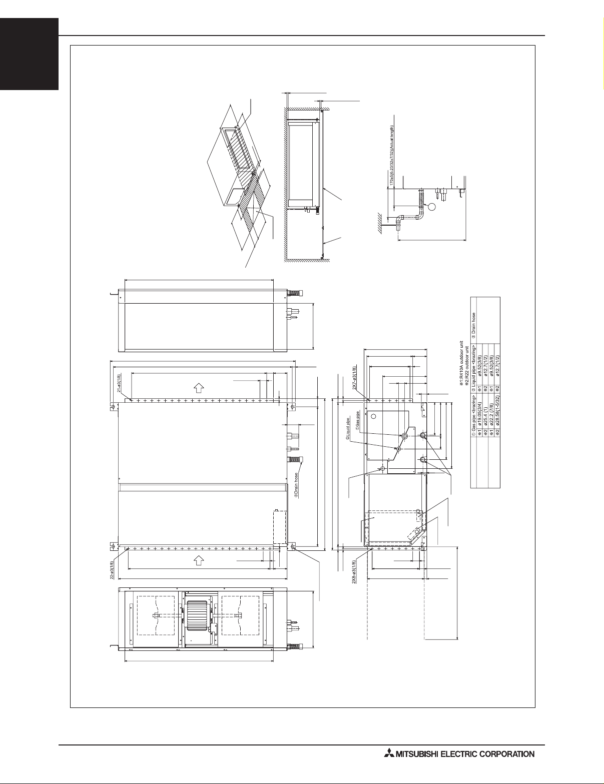
2. EXTERNAL DIMENSIONS
PEFY-P-NMHU-E
PEFY-P-NMSU-E
PEFY-P-NMAU-E
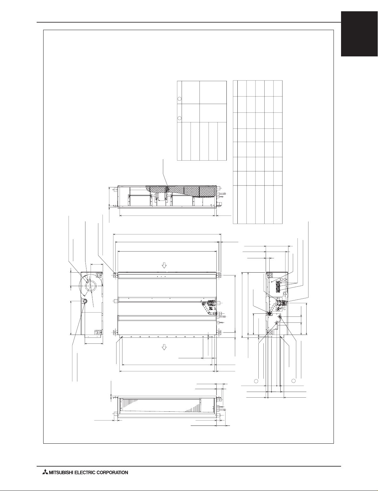
PEFY-P06, 08, 12, 15, 18, 24, 27, 30, 36, 48, 54NMAU-E
Note 1. Use M10 screw for the Suspension bolt (field supply).
2. Keep the service space for the maintenance at the bottom.
3. This chart indicates for PEFY-P24·27·30·36·48·54NMAU-E
models,which have 2 fans. PEFY-P06·08·12·15·18NMAU-E
models have 1 fan.
4. In case of the inlet duct is used,remove the air filter
(supply with the unit), then install the filter
(field supply) at suction side.
(8-5/16)
5. Ventilation air must be 0°C (32°F) or higher when accepting
ventilation into PEFY knockout hole.
18 (3/4) 210
Air filter
G
(1/4)
Ø6.35
Unit:mm(in.)
Liquid pipe
2
Gas pipe
(1/2)
Ø12.7
1
Model
PEFY-P06,08,12NMAU-E
PEFY-P15,P18NMAU-E
G
(3/8)
Ø9.52
FB CD E
(5/8)
Ø15.88
PEFY-P24,27,30NMAU-E
PEFY-P36,48NMAU-E
PEFY-P54NMAU-E
AModel
Unit:mm(in.)
21 (7/8)
858
658
1058
(41-11/16)
(33-13/16)
(25-15/16)
800
600
7
660
800
(31-1/2)
(29-11/16)
700 754
(27-9/16) (26) (23-5/8)
PEFY-P06,08,12NMAU-E
1300 1358
1000
(51-3/16) (53-1/2)
9
11
14
860
136015001454
(41-3/4) (39-3/8)
(33-7/8) (31-1/2)
1200
1000
(39-3/8)
(59-1/16) (53-9/16)
954900
1154 1060
(37-9/16)
(45-7/16) (47-1/4)
1100
1400
(55-1/8) (57-1/4)
(35-7/16)
(43-5/16)
PEFY-P15,P18NMAU-E
PEFY-P24,27,30NMAU-E
PEFY-P36,48NMAU-E
Unit : mm(in.)
15581500
(59-1/16) (61-3/8)
16
1560170016541600
(66-15/16) (61-7/16)
(63) (65-1/8)
PEFY-P54NMAU-EVent
Note 5
Suspension bolt hole
4-14x30 (9/16x1-3/16) Slot
(5-3/8)
3-Ø2.9(1/8) mounting hole
Ventilation air intake Ø100(3-15/16)
knock out hole
153 (6-1/16)
120°
378 (14-15/16)
Drain pipe(O.D. Ø32(1-1/4))
(Emergency draining)
135
120°
Ø125
(4-15/16)
200 (7-7/8)
15 (5/8)
2xE-Ø2.9(1/8)
C
B(Suspension bolt pitch)
A
Air
inlet
Air
outlet
100 (3-15/16)X(E-1)=F30 (1-3/16)
D(Duct)20 (13/16)
10 (7/16)
100 (3-15/16)
73 (2-7/8)
58 (2-5/16)
23 (15/16)
643 (25-3/8)
(Suspension bolt pitch)
57 (2-1/4)
(O.D.Ø32(1-1/4))
Drain pipe
732 (28-7/8)
700 (27-9/16)32 (1-5/16)
238 (9-3/8)
10 (7/16)
Refrigerant piping
2
250 (9-7/8)
217 (8-9/16)
41 (1-5/8)
Control box
Terminal block(Transmission)
Drain pump
brazing connection (liquid)
40 (1-5/8)
23 (15/16)178 (7-1/16)
(DUCT)
Terminal block(Power source)
Drain pipe(O.D.Ø32(1-1/4))(Gravity draining)
67136
(2-11/16)
356 (1/16)
(5-3/8)
2x2-Ø2.9(1/8)
Refrigerant piping
brazing connection (gas)
1
33 (1-5/16) 122 (4-13/16)
100 (3-15/16)
40 (1-5/8)40 (1-5/8)
100 (3-15/16)
PEFY-13PEFY-P-NMSU-E/PEFY-P-NMAU-E/PEFY-P-NMHU-E (June 2010)
Page 14
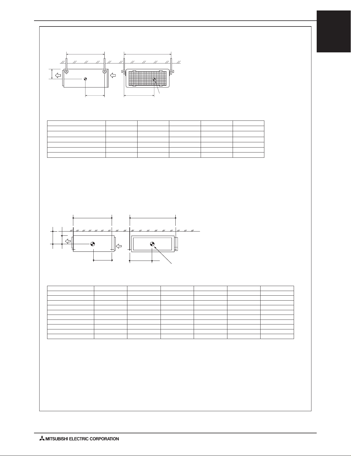
2. EXTERNAL DIMENSIONS
2. EXTERNAL DIMENSIONS
DATA U6
DATA U6
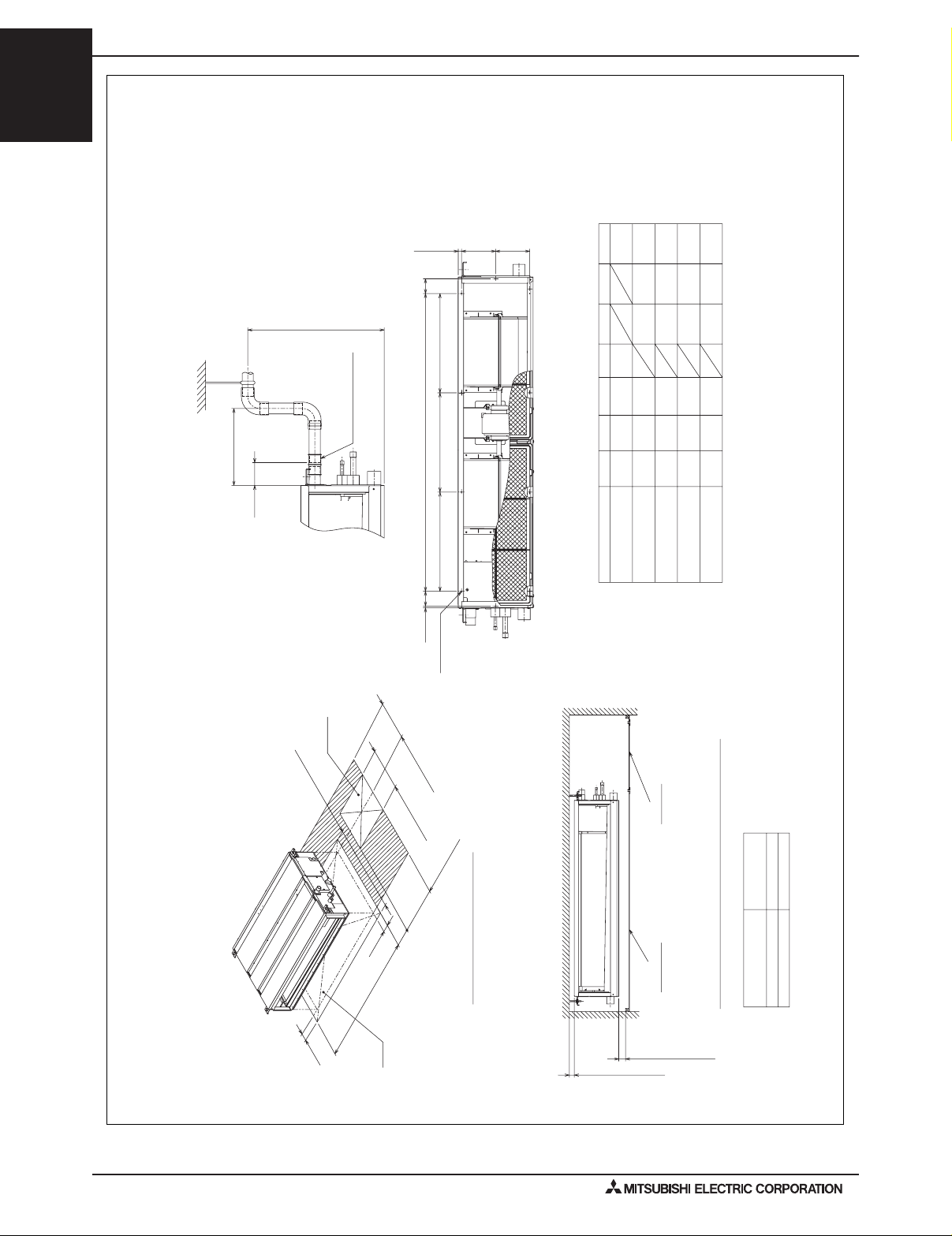
Make the access door at the appointed position properly for service maintenance.
<Suction filter box built-in specification>
Unit : mm(in.)
PEFY-P06, 08, 12, 15, 18, 24, 27, 30, 36, 48, 54NMAU-E
PEFY-P-NMAU-E
PEFY-P-NMSU-E
PEFY-P-NMHU-E
(11-13/16)
Less than 300
0
-10
65
0
-7/16
(2-9/16 )
(Actual length)
Less than 700
(27-9/16)
<accessory>
Drain hose (I.D.Ø32(1-1/4))
JKx(M-1)=NJ6 (1/4)
Unit : mm(in.)
(4-7/16) (4-7/16)
112 112 11 (7/16)
KLK
P
10410
10
12
12
Unit:mm(in.)
780
990
(39)
1280
1480
(50-7/16)
(58-5/16)(14-5/8)(2-3/16)
4
5
M
LKJN
300150
(11-13/16)
260
330
(5-15/16)(1-3/4)
44800
49
H
1000 54
1200
(31-1/2)
(39-3/8) (2-3/16) (10-1/4) (30-3/4)
Model
PEFY-P15,P18NMAU-E
PEFY-P06,08,12NMAU-E
5
370
320
(13)(1-15/16)
(12-5/8)
54
(2-3/16)(59-1/16)
1500
1700 54
(47-1/4)
(66-15/16)
PEFY-P24,27,30NMAU-E
PEFY-P36,48NMAU-E
PEFY-P54NMAU-E
Access door
777 (30-5/8)
50 (2)
50 (2)
H
Note2
P-Ø2.9 (1/8)
(11-13/16)
More than 300
450 (17-3/4)
450 (17-3/4)
250~300
(9-7/8~11-13/16)
Access door
Required space for service and maintenance
Ceiling surface
More than 10 (7/16)
L
20(13/16)
250(9-7/8)
for air filter
Maintenance type
Under maintenance
Make the access door at the appointed position properly for service maintenance.
More than 20 (13/16)
Side maintenance
PEFY-14
PEFY-P-NMSU-E/PEFY-P-NMAU-E/PEFY-P-NMHU-E (June 2010)
Page 15
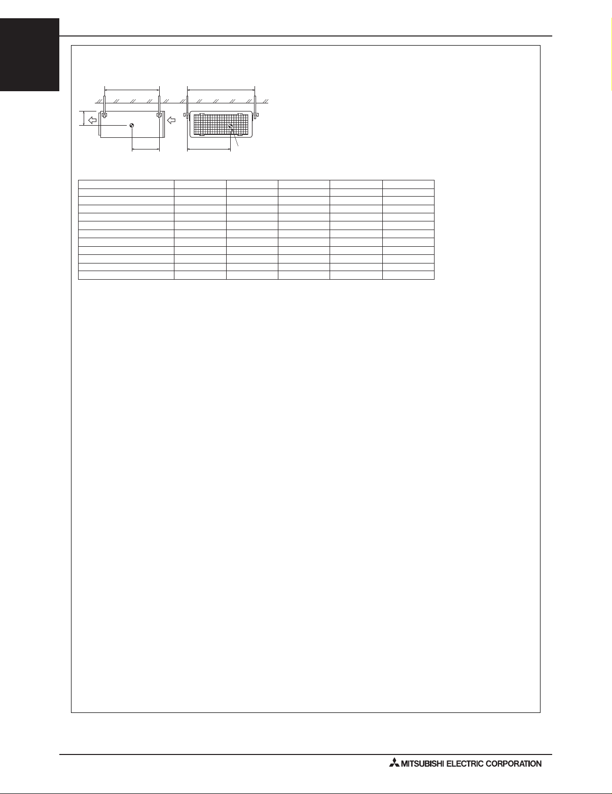
2. EXTERNAL DIMENSIONS
DATA U3
2. EXTERNAL DIMENSIONS
PEFY-P-NMHU-E
PEFY-P-NMSU-E
PEFY-P-NMAU-E
PEFY-P15,18,24,27,30,36,48,54NMHU-E
54NMHU-E models, which has 2 fans.
·
48
·
30NMHU-E models have 1 fan.
·
27
·
24
·
18
·
when the heat exchanger is cleaned.
In case field supplied air filter is used, attach it where the filter
service is easily done.
PEFY-P15
2.Keep the service space for the maintenance from the bottom
3.This chart indicates for PEFY-P36
4.Make sure to install the air filter(field supply) on the air intake side.
Note1.Use M10 screw for the Suspension bolt (field supply).
5.On Model :18,36,48,54, you would use flare nut packed with the
(24-5/8)
625
Required space for service and maintenance.
Indoor Unit, when connecting the Outdoor Unit for R22.
E
A
Air outlet
Air inlet
C
Note2
L
(1-31/32)
50
(1-31/32)
50
(17-23/32)
450
450
150~200
(17-23/32)
(27-9/16)
(5-29/32~7-7/8)
700
100~200
(3-15/16~7-7/8)
B(Suspension bolt pitch)
50(1-31/32)X(J-1)=K50
50(1-31/32)X(G-1)=H
50(1-31/32)
50(1-31/32)
Access door
(1-31/32)
80
(3-5/32)
(19/32)
15
(13/32)
10
F
20(13/16) or more
250(9-27/32)
23(29/32)
60(2-3/8)
(2-31/32)
( )
75
(2-3/8)
( )
60
904(35-19/32)
383(15-3/32)
814(32-1/16)(Suspension bolt pitch)
(1-5/8)
41
(2-25/32)
70
Suspension bolt hole
4-14X30(9/16X1-3/16) Slot
340(13-13/32)
20(13/16) or more
Ceiling surface
Access door
Make the access door at the appointed position properly for service maintenance.
15(19/32)
29(1-5/32)
847(33-3/8)
900(35-7/16)
24(31/32)
10(13/32)
Drain hole
(option)
Control box
300(11-13/16) or less
50
(1-31/32)
77130
(3-1/16)
380(14-31/32)
250(9-27/32)
328(12-15/16)
50X4=200
25(1)
(1-31/32X4=7-7/8)
50(1-31/32)
(1-31/32)X5=(9-27/32)
50X5=250
3
550(21-21/32) Max
94(3-23/32)
(5-1/8)
41
5/8)
(1-
(6-13/32)
163
343(13-17/32)
387(15-1/4)
92 200(7-7/8)
(3-5/8)
30(1-3/16)
Terminal bed
(Transmission)
Terminal box
Terminal bed
(Power source)
45(1-25/32)
17(11/16) 340(13-13/32)
Keep duct-work length 850mm(33-15/32 in.) or more.
Drw. : IU-W277664
Unit : mm(in)
When installing the drain pump kit (option).
mm(in.)
Drain hose
I.D.32mm (1-1/4inch)
<flexible joint>
(accessory)
L KJ HGFE DCBA
780
1230
1030
(40-9/16)
(48-7/16)
(30-23/32)
450
700
900
(27-9/16)
(35-7/16)
(17-23/32)
10
15
19
500
800
(19-11/16)
11
50
(1-31/32)
550
(21-21/32)
600
(23-5/8)
680
(26-25/32)
754
(29-11/16)
800
(31-1/2)
1000
(31-1/2)
17
25
25
(1)
800
1000
(31-1/2)
850
1050
(33-1/2)
930
1130
(36-5/8)
1004
1204
(39-17/32)
1050
1250
(41-11/32)
30NMHU-E
·
(39-3/8)
21
(1)
(39-3/8)
(41-11/32)
(44-1/2)
(47-13/32)
(49-7/32)
54NMHU-E
·
48
·
Drain hole
Model
PEFY-P18NMHU-E
PEFY-P36
PEFY-P24NMHU-E
PEFY-P27
D
Model:P15~30(Note3)
PEFY-P15NMHU-E
PEFY-15PEFY-P-NMSU-E/PEFY-P-NMAU-E/PEFY-P-NMHU-E (June 2010)
Page 16
2. EXTERNAL DIMENSIONS
DATA U3
2. EXTERNAL DIMENSIONS
PEFY-P72,96NMHU-E
PEFY-P-NMAU-E
PEFY-P-NMSU-E
PEFY-P-NMHU-E
when the heat exchanger is cleaned.
on the air intake side.
In case field supplied air filter is used, attach it where
the filter service is easily done.
2.Keep the service space for the maintenance from the bottom
3.Make sure to install the air filter(field supply)
packed with the Indoor Unit, when connecting
Note1.Use M10 screw for the Suspension bolt (field supply).
4.On this model, you would use pipe
Note2
(28-3/4)
730
(53-5/32)
1350
(1-31/32)
50
(1-31/32)
50
450
450
150~200
the Outdoor Unit for R22.
Required space for service and maintenance.
1100(43-5/16)
1372(54-1/32)
Air outlet
(17-23/32)
(31-1/2)
(5-29/32~7-7/8)
800
200~300
(7-7/8~11-13/16)
1326(52-7/32)(Suspension bolt pitch)23(29/32)
50(1-31/32)
(17-23/32)
Access door
(1-31/32)
50 50X20=1000(1-31/32X20=39-3/8)
(19/32)
15
100
(3-15/16)
20(13/16) or more
340(13-13/32)
60(2-3/8)1034(40-23/32)(Suspension bolt pitch)
20(13/16) or more
Ceiling surface
Access door
Make the access door at the appointed position properly for service maintenance.
29(1-5/32)
15(19/32)
470(18-17/32)
(1-31/32X6=11-13/16)
20
327(12-7/8)
105 340(13-13/32)
(4-5/32)
(13/16)
164 44
(6-15/32)
3
550(21-21/32) Max
41(1-5/8)
300(11-13/16) or less
When installing the drain pump kit (option).
50X6=300
(1-3/4)
Drw. : IU-W277665
Unit : mm(in)
mm(in.)
Drain hose
I.D.32mm (1-1/4inch)
<flexible joint >
(accessory)
Air inlet
1250(49-7/32)
110(43-5/16)
50(1-31/32)
(3-3/32)
( )
78
1120(44-1/8)
1124(44-9/32)
1067(42-1/32)
Drain hole
(option)
Control box
(13/32)
10
102 25 50X21=1050(1-31/32X21=41-11/32)
(4-1/32)
(1)
4-14X30(9/16X3/16) Slot
Suspension bolt hole
420(16-9/16)
10(13/32)
24(31/32)
50 (1-31/32)
(1-31/32X7=13-25/32)
50X7=350
420(16-9/16)
222(8-3/4)
249(9-13/16)95
422(16-5/8)
489(19-9/32)
(3-3/4)
(1-3/16)
30
Terminal bed
(Power source)
Model
PEFY-P96NMHU-E
PEFY-P72NMHU-E
Drain hole
Terminal bed
(Transmission)
35(1-13/32)
20(13/16)
Keep duct-work length 850mm(33-15/32 in.) or more.
PEFY-16
PEFY-P-NMSU-E/PEFY-P-NMAU-E/PEFY-P-NMHU-E (June 2010)
Page 17
3. CENTER OF GRAVITY
PEFY-P-NMHU-E
PEFY-P-NMSU-E
PEFY-P-NMAU-E
PEFY-P06,08,12,15,18,24NMSU-E
L
YX
752 [29-5/8]
752 [29-5/8]
752 [29-5/8]
952 [37-1/2]
952 [37-1/2]
1152 [45-3/8]
A
L
275 [10-27/32]
Z
Model name
PEFY-P06NMSU-E
PEFY-P08NMSU-E
PEFY-P12NMSU-E
PEFY-P15NMSU-E
PEFY-P18NMSU-E
PEFY-P24NMSU-E
W
W
625 [24-5/8]
625 [24-5/8]
625 [24-5/8]
625 [24-5/8]
625 [24-5/8]
625 [24-5/8]
PEFY-P15,18,24,27,30,36,48,54,72,96NMHU-E
X
263 [10-3/8]
263 [10-3/8]
280 [11-1/32]
280 [11-1/32]
285 [11-1/4]
A: Center of gravity
Y
338 [13-5/16]
338 [13-5/16]
340 [13-13/32]
422 [16-5/8]
422 [16-5/8]
511 [20-1/8]
Ref.: PEFY_NMSU_COG_USDB_ALL
(mm)[in]
Z
105 [4-5/32]
105 [4-5/32]
104 [4-1/8]
104 [4-1/8]
104 [4-1/8]
104 [4-1/8]
H
Z
Model name
PEFY-P15NMHU-E
PEFY-P18NMHU-E
PEFY-P24NMHU-E
PEFY-P27NMHU-E
PEFY-P30NMHU-E
PEFY-P36NMHU-E
PEFY-P48NMHU-E
PEFY-P54NMHU-E
PEFY-P72NMHU-E
PEFY-P96NMHU-E
W
X
814 [32-1/16]
814 [32-1/16]
814 [32-1/16]
814 [32-1/16]
814 [32-1/16]
814 [32-1/16]
814 [32-1/16]
814 [32-1/16]
1034 [40-23/32]
1034 [40-23/32]
L
Y
A
W
L
754 [29-11/16]
754 [29-11/16]
754 [29-11/16]
1004 [39-17/32]
1004 [39-17/32]
1204 [47-13/32]
1204 [47-13/32]
1204 [47-13/32]
1326 [52-7/32]
1326 [52-7/32]
210 [8-9/32]
210 [8-9/32]
210 [8-9/32]
210 [8-9/32]
210 [8-9/32]
210 [8-9/32]
210 [8-9/32]
210 [8-9/32]
255 [10-1/16]
255 [10-1/16]
H
A: Center of gravity
X
374 [14-3/4]
374 [14-3/4]
374 [14-3/4]
394 [15-17/32]
394 [15-17/32]
364 [14-11/32]
364 [14-11/32]
364 [14-11/32]
462 [18-7/32]
462 [18-7/32]
Y
440 [17-11/32]
440 [17-11/32]
440 [17-11/32]
584 [22-32/32]
584 [22-32/32]
649 [25-9/16]
649 [25-9/16]
649 [25-9/16]
660 [25-32/32]
660 [25-32/32]
(mm)[in]
Z
190 [7-1/2]
190 [7-1/2]
190 [7-1/2]
190 [7-1/2]
190 [7-1/2]
190 [7-1/2]
190 [7-1/2]
190 [7-1/2]
235 [9-9/32]
235 [9-9/32]
PEFY-17PEFY-P-NMSU-E/PEFY-P-NMAU-E/PEFY-P-NMHU-E (June 2010)
Page 18
3. CENTER OF GRAVITY
3. CENTER OF GRAVITY
DATA U6
3. CENTER OF GRAVITY
PEFY-P06, 08, 12, 15, 18, 24, 27, 30, 36, 48, 54NMAU-E
PEFY-P-NMAU-E
PEFY-P-NMSU-E
PEFY-P-NMHU-E
Z
LW
Model name
PEFY-P06NMAU-E
PEFY-P08NMAU-E
PEFY-P12NMAU-E
PEFY-P15NMAU-E
PEFY-P18NMAU-E
PEFY-P24NMAU-E
PEFY-P27NMAU-E
PEFY-P30NMAU-E
PEFY-P36NMAU-E
PEFY-P48NMAU-E
PEFY-P54NMAU-E
YX
W
643 [25 - 6/16]
643 [25 - 6/16]
643 [25 - 6/16]
643 [25 - 6/16]
643 [25 - 6/16]
643 [25 - 6/16]
643 [25 - 6/16]
643 [25 - 6/16]
643 [25 - 6/16]
643 [25 - 6/16]
643 [25 - 6/16]
A
L
754 [29 - 11/16]
754 [29 - 11/16]
754 [29 - 11/16]
954 [37 - 9/16]
954 [37 - 9/16]
1154 [45 - 7/16]
1154 [45 - 7/16]
1154 [45 - 7/16]
1454 [57 - 4/16]
1454 [57 - 4/16]
1654 [65 - 2/16]
A : Center of gravity
X
330 [13]
330 [13]
330 [13]
340 [13 - 7/16]
340 [13 - 7/16]
325 [12 - 13/16]
325 [12 - 13/16]
325 [12 - 13/16]
330 [13]
330 [13]
332 [13 - 2/16]
Y
300 [11 -13/16]
300 [11 -13/16]
300 [11 -13/16]
375 [14 -13/16]
375 [14 -13/16]
525 [20 -11/16]
525 [20 -11/16]
525 [20 -11/16]
675 [26 -10/16]
675 [26 -10/16]
725 [28 -9/16]
(mm)[in]
Z
130 [5 -2/16]
130 [5 -2/16]
130 [5 -2/16]
130 [5 -2/16]
130 [5 -2/16]
130 [5 -2/16]
130 [5 -2/16]
130 [5 -2/16]
130 [5 -2/16]
130 [5 -2/16]
130 [5 -2/16]
PEFY-18
PEFY-P-NMSU-E/PEFY-P-NMAU-E/PEFY-P-NMHU-E (June 2010)
Page 19

4. ELECTRICAL WIRING DIAGRAMS
PEFY-P-NMHU-E
PEFY-P-NMSU-E
PEFY-P-NMAU-E
PEFY-P06,08,12,15,18,24NMSU-E
CNP
(Blue)
X1
13
1351213248132 4567
U
FUSE
DSA
I.B.
CND
ZNR02
(Black)
(Blue)
CN2M
INSIDE SECTION OF CONTROL BOX
U
ZNR01
LED1
Rectify circuit
DC310~340V
CNMF
(Red)
CN20CN4FCN44CN41CN52 CN51
PULL BOX
FUSE (16A)
BREAKER (16A)
TO NEXT INDOOR UNIT
TB2
G
L2
L1
Ref.: PEFY_NMSU_EWD_USDB_ALL
POWER SUPPLY
~ 208V/230V 60Hz
M
M
t°
I.B.
Note: If using gravity drain, unplug pump
connector.
1~
CONTROL BOX
Drainpump
Fan motor
TB2TB15TB5A.B.
PARTS LOCATION
SW2SW4SW3
CN42CN81CN32
ON
OFF
(Red)
(Red)
CN3A
1
SWE
LED2
(Blue)
CN90
3
1
CN27
(Red)
(Yellow)
CN4Y CN24
CN60
432
(Green)
6
5
A.B.
1324 12 14567
4231
8765432
432
1
SW5
CN43
SWBSWA
SW1
1
3
2
1
0
F
E
D
1
0
9
1
0
9
2
8
2
8
4
C
CN82
5
6
A
B
3
4
7
3
4
7
7
8
9
SWC
6
6
TB15
12
S(SHIELD)
M2
M1
TB5
SW14
(Connection No.)
5
SW11
(1st digit)
5
SW12
(2nd digit)
FSTH22 TH23 TH21
t° t°
M
LEV
TO MA REMOTE
CONTROLLER
NOTE:1.The wirings to TB2,TB5,TB15 shown in dotted line are field work.
TO OUTDOOR UNIT
BC CONTROLLER
REMOTE CONTROLLER
Switch (for model selection)
Connector (emergency operation)
Switch (for mode selection)
Switch (2nd digit address set)
Switch (connection No.set)
Switch (for mode selection)
SYMBOLNAME
SW3(I.B.)
Switch (for mode selection)
SW1(A.B.)
SW4(I.B.)
SW5(A.B.)
SWE(I.B.)
Switch (for static pressure selection)
Switch (for model selection)
Switch (1st digit address set)
SW11(A.B.)
SW12(A.B.)
Switch (for static pressure selection)
SW14(A.B.)
SWB(A.B.)
SWA(A.B.)
SWC(A.B.)
NAMESYMBOLSYMBOL
2.Mark indicates terminal bed, connector.
3.Use copper supply wire.
Connector (HA terminal-A)
Connector (Centrally control)
Connector (Remote switch)
CN32
CN51
CN41
Connector (Drain Safety)CN4Y
Connector (Wireless)
Float switchFS
Connector (Remote indication)
CN90
CN52
Switch (for capacity code)
Thermistor (piping temp.detection/liquid)
Thermistor (piping temp.detection/gas)
TH21 Thermistor (inlet air temp.detection)
TH23
TH22
SW2(I.B.)
NAME
Transmission terminal bedTB15
Power source terminal bed
Indoor controller board
Address board
I.B.
A.B.
SYMBOL EXPLANATION
Fuse AC250V 6.3AFUSE
TB2
TB5 Transmission terminal bed
ArresterDSA
VaristorZNR01,02
X1 Aux. relay
Connector (Heater)CN24
Connector (Damper)
CN27
PEFY-19PEFY-P-NMSU-E/PEFY-P-NMAU-E/PEFY-P-NMHU-E (June 2010)
Page 20

PEFY-P-NMSU-E
4. ELECTRICAL WIRING DIAGRAMS
PEFY-P-NMAU-E
PEFY-P-NMHU-E
Note: If using gravity drain,
unplug pump connector.
External Heater
PEFY-20
PEFY-P-NMSU-E/PEFY-P-NMAU-E/PEFY-P-NMHU-E (June 2010)
Page 21

4. ELECTRICAL WIRING DIAGRAMS
PEFY-P-NMHU-E
PEFY-P-NMSU-E
PEFY-P-NMAU-E
PEFY-P15,18,24,27,30,36,48,54NMHU-E
PULL BOX
FUSE(15A)
BC CONTROLLER
ME REMOTE CONTROLLER
TO OUTDOOR UNIT
TO MA REMOTE CONTROLLER
TB15 (TRANSMISSION TERMINAL BED)
2
1
1
3
I.B.
CN3A
(Blue)
31
5
INSIDE SECTION OF CONTROL BOX
FAN2
(Yellow)
(White)(Yellow)(Green)(Red)(Green)
CN24 CN22CN27CN25CN23
(Green)(White) (White) (White)
CN32 CN52 CN51 CN41
SW2
SW3
SW4
CN42
(Red)
4
123
123
TB5 (TRANSMISSION TERMINAL BED)
M2
S(SHIELD)
2
(Blue)
XO4XO6 XO5
XO1
ZNR
F1
AC250V
6.3A T
( )
LED2
LED1
(Red)
4
CN81
5
M1
S.B.
1
CN2M
FAN3
(White)
71
3
CNP
(Blue)
3
CND
(Red)
31
CNT
(White)
1
31
1
CN3T
(Red)
3
1
2
3
4
56
CN60
(White)
12
CN31
(White)
1
2
CN29
(Black)(Red)
1
2
CN21
(White)
1
2
CN20
7
8
6
TO NEXT INDOOR UNIT
1
3
CN1
(Yellow)
DSA1
ZNR1
5A F
AC250V
( )
F2
1
1
T
1
*A
31
CN31
65
1234
A.B.
2
2
2
TB2
L1
CN62
CN82
8
G
L2
*insert
*A connector is
attached to the
drain pump kit,
which is an
SW7
SW5
(White)
SW1
(White)
6
5
7
4
C
0
0
BREAKER(15A)
131
3
44
(Red)
5
8
8
9
9
1
36
3
(Blue)
89189
1
1
3
3
4
4
5
6
8
8
9
9
(White)
*NOTE 1,2
optional part.
DS
3
2
1
4
5
9
6
7
8
(1st digit)
SW11
3
2
1
4
5
9
6
7
8
(2nd digit)
SW12
4
3
5
2
6
1
7
0
8
F
9
E
A
B
D
C
(Connection No.)
SW14
2
3
1
POWER SUPPLY
~ 208/230V 60Hz
TO DUCT
MF
Color/External static pressure
Red/High Pressure
Blue/Low Pressure
White/Middle Pressure
attachment to alter the external static pressure on the fan
DP
*NOTE 1
Note: If using gravity drain,
unplug pump connector.
LEV
*NOTE 1
TH23
TH21 TH22
Drw. : IU-W660134
I.B.
C
NAMESYMBOL
NAMESYMBOL
(The Drain Pump operates continuously if the connector is inserted
connector or fastening connector of control board.
After the test run, make sure to remove the *A connector.
4.Mark indicates terminal bed, connector, board insertion
2.*A in the chart is the connector for a drain pump test run operation.
3.The wirings to TB2,TB5,TB15 shown in chained line are field work.
and the power is supplied.)
NOTE;1.The part of the broken line indicates the circuit for optional parts.
NAME
SYMBOL
SYMBOL EXPLANATION
TB5,TB15
CONTROL BOX
A.B.TB2
S.B.
PARTS LOCATION
Thermistor (piping temp.detection/liquid)
Thermistor (inlet temp.detection)TH21
Thermistor (piping temp.detection/gas)
Switch(for mode selection)
Switch (2nd digit address set)
Switch (1st digit address set)
TH22
TH23
SW11(A.B.)
SW12(A.B.)
Surge absorber boardS.B.
ConnectorCN22
Power supply (I.B.)
Power supply (Remote controller)
Drain sensor
LED2
LED1
<DS>
Power source terminal bed
Fan motor
Capacitor (for MF)
Indoor controller board
Address board
C
MF
I.B.
TB2
A.B.
Switch(for capacity code)
Switch (connection No.set)
SW14(A.B.)
ConnectorCN23
TB5 Transmission terminal bed
Switch(for mode selection)
Switch(for model selection)
Switch(for voltage selection)
Switch(for model selection)
SW1(A.B.)
SW5(A.B.)
SW7(A.B.)
SW4(I.B.)
SW2(I.B.)
SW3(I.B.)
ConnectorCN27
Connector (Humidifier)CN25
Connector (External Heater)CN24
Connector (Centrally control)
Connector (HA terminal-A)
Connector (Centrally control)
CN51
CN41
CN32
Transmission terminal bedTB15
Fuse AC250V 5A F
Fuse AC250V 6.3A TF1
Electronic linear expan.valve
Transformer
Drain pump
T
LEV
<F2>
<DP>
Aux.relay
Inside < > is the optional parts.
X01,X04~X06
Connector (Remote indication)
CN52
Varistor
ZNR,ZNR1
PEFY-21PEFY-P-NMSU-E/PEFY-P-NMAU-E/PEFY-P-NMHU-E (June 2010)
Page 22

4. ELECTRICAL WIRING DIAGRAMS
PEFY-P-NMSU-E
PEFY-P72,96NMHU-E
PEFY-P-NMAU-E
PEFY-P-NMHU-E
TO MA REMOTE CONTROLLER
TB15 (TRANSMISSION TERMINAL BED)
2
1
1
3
I.B.
(Blue)
CN3A
XO4XO5XO6
531
FAN2
(Yellow)
INSIDE SECTION OF CONTROL BOX
(Green)(Red)(White)(Yellow)(Green)
CN27 CN22CN23 CN24 CN25
CN41CN51CN52CN32
(White)(Green)(White) (White)
SW2
SW3
SW4
(Red)
CN42
4
123
123
BC CONTROLLER
ME REMOTE CONTROLLER
TO OUTDOOR UNIT
TB5 (TRANSMISSION TERMINAL BED)
S(SHIELD)
M2
M1
1
3
S.B.
CN1
1
2
(Yellow)
DSA1
ZNR1
(Blue)
CN2M
FAN3
(White)
7
5
3
1
52F
51F
CR
CNP
(Blue)
XO1
3
CND
(Red)
ZNR
31
F1
CNT
(White)
6.3A T
1
AC250V
( )
31
T
1
(Red)(White)
CN3T
3
CN60
2
CN31
(White)
1
2
(Black)(White)(Red)
CN29
LED2
11
2
CN21CN20
1
2
LED1
(Red)
CN81
4
5
7
6
8
*A
1
2
3
4
5
6
31
CN31
56
1234
A.B.
1
1
1
CN62
CN82
8
2
2
2
(White)
(White)
7
BREAKER
TB2
52F
51F
F2
6
5
POWER SUPPLY
3~ 208V/230V 60Hz
GL3L2
L1
( 9A )
5A F
AC250V
( )
*NOTE 1,2
LEV adapter board
*A connector is attached
to the drain pump kit,
which is an optional part.
654321
3
2
1
4
5
0
9
6
7
8
(1st digit)
SW11
SW7
3
2
1
4
5
0
9
6
7
8
(2nd digit)
SW12
SW5
4
3
5
2
6
1
7
0
8
F
9
E
A
B
D
SW1
C
SW14
(Connection No.)
2
3
4
1
Drw. : IU-W660130
I.B.
A.B.
TO DUCT
51F
(Blue)
89
4
5
6
9
95
8
8
6
MF
1234
1
2
3
(White)
DP
LEV2
654321
123456
123456654321
LEV1
DS
*NOTE 1
TH23
TH22
TH21
52F
S.B.
TB2
Color/External static pressure
White/High Pressure
Blue/Low Pressure
49F
*NOTE 1
Note: If using gravity drain,
unplug pump connector.
NAMESYMBOL
Thermistor (piping temp.detection/liquid)
Thermistor (inlet temp.detection)TH21
TH22
Contactor (fan motor)
Over current relay (fan motor)
52F
51F
SYMBOL NAME
is installed. Therefore, do not change factory set value of Over
current relays.
(The Drain Pump operates continuously if the connector is inserted
After the test run, make sure to remove the *A connector.
connector or fastening connector of control board.
and the power is supplied.)
3.The wirings to TB2,TB5,TB15 shown in chained line are field work.
4.Mark indicates terminal bed, connector, board insertion
2.*A in the chart is the connector for a drain pump test run operation.
CAUTION;1.To protect Fan motor from abnormal current, Over current relays<51F>
NOTE;1.The part of the broken line indicates the circuit for optional parts.
NAME
Indoor controller board
Fan motor
MF
I.B.
SYMBOL
SYMBOL EXPLANATION
CONTROL BOX
TB5,TB15
PARTS LOCATION
Switch (1st digit address set)
Switch (2nd digit address set)
Switch (connection No.set)
Switch(for mode selection)
Switch(for voltage selection)
Switch(for model selection)
Switch(for capacity code)
Switch(for mode selection)
Switch(for model selection)
Aux.relay
Thermistor (piping temp.detection/gas)
TH23
SW14(A.B.)
SW12(A.B.)
SW11(A.B.)
Power supply (Remote controller)
Power supply (I.B.)
LED2
LED1
Power source terminal bed
Address board
TB2
A.B.
ConnectorCN22
Transmission terminal bedTB5
ConnectorCN23
TB15 Transmission terminal bed
SW1(A.B.)
Connector (External Heater)CN24
F1 Fuse AC250V 6.3A T
SW7(A.B.)
SW5(A.B.)
ConnectorCN27
Connector (Humidifier) CN25
Fuse AC250V 5A F
Transformer
T
<F2>
Inner thermostat
49F
SW4(I.B.)
SW3(I.B.)
SW2(I.B.)
X01,X04~X06
Connector (Centrally control)
Connector (HA terminal-A)
Connector (Centrally control)
Connector (Remote indication)CN52
CN51
CN41
CN32
Varistor
Electronic linear expan.valve
Drain pump
Drain sensor
S.B. Surge absorber board
<DS>
<DP>
ZNR,ZNR1
LEV1,LEV2
Inside < > is the optional parts.
PEFY-22
PEFY-P-NMSU-E/PEFY-P-NMAU-E/PEFY-P-NMHU-E (June 2010)
Page 23

5. SOUND PRESSURE LEVELS
DATA U6
5-1. Sound Pressure Levels
PEFY-P-NMHU-E
PEFY-P-NMSU-E
PEFY-P-NMAU-E
3-1/4ft.
(1m)
Aux.duct
Measurement location
6-1/2ft.
(2.0m)
(1.5m)
4-7/8ft.
Measured in an anechoic room.
Sound level at anechoic room : Low-Mid-High
Model Sound pressure level dB(A)
35Pa 50Pa 70Pa 100Pa 150Pa
PEFY-P06NMAU-E 26-27-28 26-28-29 26-29-31 27-30-33 28-33-37
PEFY-P08NMAU-E 26-27-28 26-28-29 26-29-31 27-30-33 28-33-37
PEFY-P12NMAU-E 28-30-34 28-30-34 29-32-36 29-33-37 31-35-40
PEFY-P15NMAU-E 28-30-34 28-30-34 29-32-36 29-33-37 32-36-40
PEFY-P18NMAU-E 28-31-35 28-32-35 29-33-37 30-34-38 32-37-41
PEFY-P24NMAU-E 29-32-35 29-32-36 30-33-38 31-35-39 33-38-41
PEFY-P27NMAU-E 30-33-37 30-34-38 31-36-39 33-37-41 36-41-44
PEFY-P30NMAU-E 30-33-37 30-34-38 31-36-39 33-37-41 36-41-44
PEFY-P36NMAU-E 31-36-40 32-37-41 33-38-42 35-39-43 37-42-45
PEFY-P48NMAU-E 35-40-44 35-40-44 37-41-45 38-42-46 39-44-47
PEFY-P54NMAU-E 36-41-45 36-41-45 38-42-46 39-43-47 40-45-48
PEFY-23PEFY-P-NMSU-E/PEFY-P-NMAU-E/PEFY-P-NMHU-E (June 2010)
Page 24

PEFY-P-NMSU-E
10.0
15.0
20.0
25.0
30.0
35.0
40.0
45.0
50.0
55.0
60.0
65.0
70.0
63 125 250 500 1k 2k 4k 8k
NC-60
NC-50
Octave band pressure level (dB) 0dB=20μPa
Approximate minimum
audible limit on
continuous noise
NC-40
NC-30
NC-20
Octave band center frequencies (Hz)
High
Middle
60Hz
Low
60Hz
60Hz
Ref.:PEFY_NMSU_NCC_USDB_P06-1
PEFY-P06NMSU-E
External Static Pressure: 5Pa,0.02[in.WG]
Power Source: 208/230V(60Hz)
10.0
15.0
20.0
25.0
30.0
35.0
40.0
45.0
50.0
55.0
60.0
65.0
70.0
63 125 250 500 1k 2k 4k 8k
NC-60
NC-50
Octave band pressure level (dB) 0dB=20μPa
Approximate minimum
audible limit on
continuous noise
NC-40
NC-30
NC-20
Octave band center frequencies (Hz)
High
Middle
60Hz
Low
60Hz
60Hz
Ref.:PEFY_NMSU_NCC_USDB_P06-2
PEFY-P06NMSU-E
External Static Pressure: 15Pa,0.06[in.WG]
Power Source: 208/230V(60Hz)
10.0
15.0
20.0
25.0
30.0
35.0
40.0
45.0
50.0
55.0
60.0
65.0
70.0
63 125 250 500 1k 2k 4k 8k
NC-60
NC-50
Octave band pressure level (dB) 0dB=20μPa
Approximate minimum
audible limit on
continuous noise
NC-40
NC-30
NC-20
Octave band center frequencies (Hz)
High
Middle
60Hz
Low
60Hz
60Hz
Ref.:PEFY_NMSU_NCC_USDB_P06-3
PEFY-P06NMSU-E
External Static Pressure: 35Pa,0.14[In.WG]
Power Source: 208/230V(60Hz)
10.0
15.0
20.0
25.0
30.0
35.0
40.0
45.0
50.0
55.0
60.0
65.0
70.0
63 125 250 500 1k 2k 4k 8k
NC-60
NC-50
Octave band pressure level (dB) 0dB=20μPa
Approximate minimum
audible limit on
continuous noise
NC-40
NC-30
NC-20
Octave band center frequencies (Hz)
High
Middle
60Hz
Low
60Hz
60Hz
Ref.:PEFY_NMSU_NCC_USDB_P06-4
PEFY-P06NMSU-E
External Static Pressure: 50Pa,0.20[in.WG]
Power Source: 208/230V(60Hz)
10.0
15.0
20.0
25.0
30.0
35.0
40.0
45.0
50.0
55.0
60.0
65.0
70.0
63 125 250 500 1k 2k 4k 8k
NC-60
NC-50
Octave band pressure level (dB) 0dB=20μPa
Approximate minimum
audible limit on
continuous noise
NC-40
NC-30
NC-20
Octave band center frequencies (Hz)
High
Middle
60Hz
Low
60Hz
60Hz
Ref.:PEFY_NMSU_NCC_USDB_P08-1
PEFY-P08NMSU-E
External Static Pressure: 5Pa,0.02[in.WG]
Power Source: 208/230V(60Hz)
10.0
15.0
20.0
25.0
30.0
35.0
40.0
45.0
50.0
55.0
60.0
65.0
70.0
63 125 250 500 1k 2k 4k 8k
NC-60
NC-50
Octave band pressure level (dB) 0dB=20μPa
Approximate minimum
audible limit on
continuous noise
NC-40
NC-30
NC-20
Octave band center frequencies (Hz)
High
Middle
60Hz
Low
60Hz
60Hz
Ref.:PEFY_NMSU_NCC_USDB_P08-2
PEFY-P08NMSU-E
External Static Pressure: 15Pa,0.06[in.WG]
Power Source: 208/230V(60Hz)
5. SOUND LEVELS
DATA U4
PEFY
5. SOUND PRESSURE LEVELS
5-2. NC Curves
PEFY-P-NMAU-E
PEFY-P-NMHU-E
PEFY-P08NMSU-E
External Static Pressure: 35Pa,0.14[in.WG]
Power Source: 208/230V(60Hz)
70.0
65.0
60.0
55.0
50.0
45.0
40.0
35.0
30.0
25.0
20.0
Approximate minimum
audible limit on
15.0
continuous noise
Octave band pressure level (dB) 0dB=20μPa
10.0
63 125 250 500 1k 2k 4k 8k
Octave band center frequencies (Hz)
PEFY-P12NMSU-E
External Static Pressure: 15Pa,0.06[in.WG]
Power Source: 208/230V(60Hz)
70.0
65.0
60.0
55.0
50.0
45.0
40.0
35.0
30.0
25.0
20.0
Approximate minimum
audible limit on
15.0
continuous noise
Octave band pressure level (dB) 0dB=20μPa
10.0
63 125 250 500 1k 2k 4k 8k
Octave band center frequencies (Hz)
PEFY-24
PEFY-P-NMSU-E/PEFY-P-NMAU-E/PEFY-P-NMHU-E (June 2010)
PEFY-P08NMSU-E
External Static Pressure: 50Pa,0.20[in.WG]
Power Source: 208/230V(60Hz)
60Hz
High
60Hz
Middle
60Hz
Low
NC-60
NC-50
Ref.:PEFY_NMSU_NCC_USDB_P08-3
High
Middle
Low
Ref.:PEFY_NMSU_NCC_USDB_P12-2
NC-40
NC-30
NC-20
60Hz
60Hz
60Hz
NC-60
NC-50
NC-40
NC-30
NC-20
70.0
65.0
60.0
55.0
50.0
45.0
40.0
35.0
30.0
25.0
20.0
15.0
Octave band pressure level (dB) 0dB=20μPa
10.0
PEFY-P12NMSU-E
External Static Pressure: 35Pa,0.14[in.WG]
Power Source: 208/230V(60Hz)
70.0
65.0
60.0
55.0
50.0
45.0
40.0
35.0
30.0
25.0
20.0
15.0
Octave band pressure level (dB) 0dB=20μPa
10.0
High
Middle
Low
Approximate minimum
audible limit on
continuous noise
63 125 250 500 1k 2k 4k 8k
Octave band center frequencies (Hz)
Ref.:PEFY_NMSU_NCC_USDB_P08-4
High
Middle
Low
Approximate minimum
audible limit on
continuous noise
63 125 250 500 1k 2k 4k 8k
Octave band center frequencies (Hz)
Ref.:PEFY_NMSU_NCC_USDB_P12-3
PEFY-P12NMSU-E
External Static Pressure: 5Pa,0.02[in.WG]
Power Source: 208/230V(60Hz)
60Hz
60Hz
60Hz
NC-60
NC-50
NC-40
NC-30
NC-20
70.0
65.0
60.0
55.0
50.0
45.0
40.0
35.0
30.0
25.0
20.0
Approximate minimum
audible limit on
15.0
continuous noise
Octave band pressure level (dB) 0dB=20μPa
10.0
63 125 250 500 1k 2k 4k 8k
Octave band center frequencies (Hz)
PEFY-P12NMSU-E
External Static Pressure: 50Pa,0.20[in.WG]
Power Source: 208/230V(60Hz)
60Hz
60Hz
60Hz
NC-60
NC-50
NC-40
NC-30
NC-20
70.0
65.0
60.0
55.0
50.0
45.0
40.0
35.0
30.0
25.0
20.0
Approximate minimum
audible limit on
15.0
continuous noise
Octave band pressure level (dB) 0dB=20μPa
10.0
63 125 250 500 1k 2k 4k 8k
Octave band center frequencies (Hz)
High
Middle
Low
Ref.:PEFY_NMSU_NCC_USDB_P12-1
High
Middle
Low
Ref.:PEFY_NMSU_NCC_USDB_P12-4
60Hz
60Hz
60Hz
60Hz
60Hz
60Hz
NC-60
NC-50
NC-40
NC-30
NC-20
NC-60
NC-50
NC-40
NC-30
NC-20
Page 25

5. SOUND PRESSURE LEVELS
5. SOUND LEVELS
DATA U4
PEFY
10.0
15.0
20.0
25.0
30.0
35.0
40.0
45.0
50.0
55.0
60.0
65.0
70.0
63 125 250 500 1k 2k 4k 8k
NC-60
NC-50
Octave band pressure level (dB) 0dB=20μPa
Approximate minimum
audible limit on
continuous noise
NC-40
NC-30
NC-20
Octave band center frequencies (Hz)
High
Middle
60Hz
Low
60Hz
60Hz
Ref.:PEFY_NMSU_NCC_USDB_P08-3
PEFY-P08NMSU-E
External Static Pressure: 35Pa,0.14[in.WG]
Power Source: 208/230V(60Hz)
10.0
15.0
20.0
25.0
30.0
35.0
40.0
45.0
50.0
55.0
60.0
65.0
70.0
63 125 250 500 1k 2k 4k 8k
NC-60
NC-50
Octave band pressure level (dB) 0dB=20μPa
Approximate minimum
audible limit on
continuous noise
NC-40
NC-30
NC-20
Octave band center frequencies (Hz)
High
Middle
60Hz
Low
60Hz
60Hz
Ref.:PEFY_NMSU_NCC_USDB_P08-4
PEFY-P08NMSU-E
External Static Pressure: 50Pa,0.20[in.WG]
Power Source: 208/230V(60Hz)
10.0
15.0
20.0
25.0
30.0
35.0
40.0
45.0
50.0
55.0
60.0
65.0
70.0
63 125 250 500 1k 2k 4k 8k
NC-60
NC-50
Octave band pressure level (dB) 0dB=20μPa
Approximate minimum
audible limit on
continuous noise
NC-40
NC-30
NC-20
Octave band center frequencies (Hz)
High
Middle
60Hz
Low
60Hz
60Hz
Ref.:PEFY_NMSU_NCC_USDB_P12-1
PEFY-P12NMSU-E
External Static Pressure: 5Pa,0.02[in.WG]
Power Source: 208/230V(60Hz)
10.0
15.0
20.0
25.0
30.0
35.0
40.0
45.0
50.0
55.0
60.0
65.0
70.0
63 125 250 500 1k 2k 4k 8k
NC-60
NC-50
Octave band pressure level (dB) 0dB=20μPa
Approximate minimum
audible limit on
continuous noise
NC-40
NC-30
NC-20
Octave band center frequencies (Hz)
High
Middle
60Hz
Low
60Hz
60Hz
Ref.:PEFY_NMSU_NCC_USDB_P12-2
PEFY-P12NMSU-E
External Static Pressure: 15Pa,0.06[in.WG]
Power Source: 208/230V(60Hz)
10.0
15.0
20.0
25.0
30.0
35.0
40.0
45.0
50.0
55.0
60.0
65.0
70.0
63 125 250 500 1k 2k 4k 8k
NC-60
NC-50
Octave band pressure level (dB) 0dB=20μPa
Approximate minimum
audible limit on
continuous noise
NC-40
NC-30
NC-20
Octave band center frequencies (Hz)
High
Middle
60Hz
Low
60Hz
60Hz
Ref.:PEFY_NMSU_NCC_USDB_P12-3
PEFY-P12NMSU-E
External Static Pressure: 35Pa,0.14[in.WG]
Power Source: 208/230V(60Hz)
10.0
15.0
20.0
25.0
30.0
35.0
40.0
45.0
50.0
55.0
60.0
65.0
70.0
63 125 250 500 1k 2k 4k 8k
NC-60
NC-50
Octave band pressure level (dB) 0dB=20μPa
Approximate minimum
audible limit on
continuous noise
NC-40
NC-30
NC-20
Octave band center frequencies (Hz)
High
Middle
60Hz
Low
60Hz
60Hz
Ref.:PEFY_NMSU_NCC_USDB_P12-4
PEFY-P12NMSU-E
External Static Pressure: 50Pa,0.20[in.WG]
Power Source: 208/230V(60Hz)
5. SOUND LEVELS
DATA U4
PEFY-P-NMHU-E
PEFY-P-NMSU-E
PEFY-P-NMAU-E
PEFY-P15NMSU-E
External Static Pressure: 5Pa,0.02[in.WG]
Power Source: 208/230V(60Hz)
70.0
65.0
60.0
55.0
50.0
45.0
40.0
35.0
30.0
25.0
20.0
Approximate minimum
audible limit on
15.0
Octave band pressure level (dB) 0dB=20μPa
continuous noise
10.0
63 125 250 500 1k 2k 4k 8k
PEFY-P15NMSU-E
External Static Pressure: 50Pa,0.20[in.WG]
Power Source: 208/230V(60Hz)
70.0
65.0
60.0
55.0
50.0
45.0
40.0
35.0
30.0
25.0
20.0
Approximate minimum
audible limit on
15.0
Octave band pressure level (dB) 0dB=20μPa
continuous noise
10.0
63 125 250 500 1k 2k 4k 8k
PEFY-P18NMSU-E
External Static Pressure: 35Pa,0.14[in.WG]
Power Source: 208/230V(60Hz)
70.0
65.0
60.0
55.0
50.0
45.0
40.0
35.0
30.0
25.0
20.0
Approximate minimum
audible limit on
15.0
Octave band pressure level (dB) 0dB=20μPa
continuous noise
10.0
63 125 250 500 1k 2k 4k 8k
PEFY-P24NMSU-E
External Static Pressure: 15Pa,0.06[in.WG]
Power Source: 208/230V(60Hz)
70.0
65.0
60.0
55.0
50.0
45.0
40.0
35.0
30.0
25.0
20.0
Approximate minimum
audible limit on
15.0
Octave band pressure level (dB) 0dB=20μPa
continuous noise
10.0
63 125 250 500 1k 2k 4k 8k
High
Middle
Low
Octave band center frequencies (Hz)
Octave band center frequencies (Hz)
Octave band center frequencies (Hz)
Octave band center frequencies (Hz)
Ref.:PEFY_NMSU_NCC_USDB_P15-1
High
Middle
Low
Ref.:PEFY_NMSU_NCC_USDB_P15-4
High
Middle
Low
Ref.:PEFY_NMSU_NCC_USDB_P18-3
High
Middle
Low
Ref.:PEFY_NMSU_NCC_USDB_P24-2
PEFY-P15NMSU-E
External Static Pressure: 15Pa,0.06[in.WG]
Power Source: 208/230V(60Hz)
60Hz
60Hz
60Hz
NC-60
NC-50
NC-40
NC-30
NC-20
60Hz
60Hz
60Hz
NC-60
NC-50
NC-40
NC-30
NC-20
60Hz
60Hz
60Hz
NC-60
NC-50
NC-40
NC-30
NC-20
70.0
65.0
60.0
55.0
50.0
45.0
40.0
35.0
30.0
25.0
20.0
Approximate minimum
audible limit on
15.0
Octave band pressure level (dB) 0dB=20μPa
continuous noise
10.0
63 125 250 500 1k 2k 4k 8k
PEFY-P18NMSU-E
External Static Pressure: 5Pa,0.02[in.WG]
Power Source: 208/230V(60Hz)
Octave band pressure level (dB) 0dB=20μPa
PEFY-P18NMSU-E
External Static Pressure: 50Pa,0.20[in.WG]
Power Source: 208/230V(60Hz)
Octave band pressure level (dB) 0dB=20μPa
Octave band center frequencies (Hz)
70.0
65.0
60.0
55.0
50.0
45.0
40.0
35.0
30.0
25.0
20.0
Approximate minimum
audible limit on
15.0
continuous noise
10.0
63 125 250 500 1k 2k 4k 8k
Octave band center frequencies (Hz)
70.0
65.0
60.0
55.0
50.0
45.0
40.0
35.0
30.0
25.0
20.0
Approximate minimum
audible limit on
15.0
continuous noise
10.0
63 125 250 500 1k 2k 4k 8k
Octave band center frequencies (Hz)
PEFY-P24NMSU-E
External Static Pressure: 35Pa,0.14[in.WG]
Power Source: 208/230V(60Hz)
60Hz
60Hz
60Hz
NC-60
NC-50
NC-40
NC-30
NC-20
70.0
65.0
60.0
55.0
50.0
45.0
40.0
35.0
30.0
25.0
20.0
Approximate minimum
audible limit on
15.0
Octave band pressure level (dB) 0dB=20μPa
continuous noise
10.0
63 125 250 500 1k 2k 4k 8k
Octave band center frequencies (Hz)
60Hz
High
60Hz
Middle
60Hz
Low
Ref.:PEFY_NMSU_NCC_USDB_P15-2
60Hz
High
60Hz
Middle
60Hz
Low
Ref.:PEFY_NMSU_NCC_USDB_P18-1
60Hz
High
60Hz
Middle
60Hz
Low
Ref.:PEFY_NMSU_NCC_USDB_P18-4
60Hz
High
60Hz
Middle
60Hz
Low
Ref.:PEFY_NMSU_NCC_USDB_P24-3
PEFY-P15NMSU-E
External Static Pressure: 35Pa,0.14[in.WG]
Power Source: 208/230V(60Hz)
70.0
65.0
NC-60
NC-50
NC-40
NC-30
NC-20
NC-60
NC-50
NC-40
NC-30
NC-20
NC-60
NC-50
NC-40
NC-30
NC-20
60.0
55.0
50.0
45.0
40.0
35.0
30.0
25.0
20.0
Approximate minimum
audible limit on
15.0
Octave band pressure level (dB) 0dB=20μPa
continuous noise
10.0
63 125 250 500 1k 2k 4k 8k
PEFY-P18NMSU-E
External Static Pressure: 15Pa,0.06[in.WG]
Power Source: 208/230V(60Hz)
Octave band pressure level (dB) 0dB=20μPa
PEFY-P24NMSU-E
External Static Pressure: 5Pa,0.02[in.WG]
Power Source: 208/230V(60Hz)
Octave band pressure level (dB) 0dB=20μPa
Octave band center frequencies (Hz)
70.0
65.0
60.0
55.0
50.0
45.0
40.0
35.0
30.0
25.0
20.0
Approximate minimum
audible limit on
15.0
continuous noise
10.0
63 125 250 500 1k 2k 4k 8k
Octave band center frequencies (Hz)
70.0
65.0
60.0
55.0
50.0
45.0
40.0
35.0
30.0
25.0
20.0
15.0
10.0
Approximate minimum
audible limit on
continuous noise
63 125 250 500 1k 2k 4k 8k
Octave band center frequencies (Hz)
High
Middle
Low
Ref.:PEFY_NMSU_NCC_USDB_P15-3
Ref.:PEFY_NMSU_NCC_USDB_P18-2
Ref.:PEFY_NMSU_NCC_USDB_P24-1
PEFY-P24NMSU-E
External Static Pressure: 50Pa,0.20[in.WG]
Power Source: 208/230V(60Hz)
70.0
65.0
NC-60
NC-50
NC-40
NC-30
NC-20
60.0
55.0
50.0
45.0
40.0
35.0
30.0
25.0
20.0
Approximate minimum
audible limit on
15.0
Octave band pressure level (dB) 0dB=20μPa
continuous noise
10.0
63 125 250 500 1k 2k 4k 8k
Octave band center frequencies (Hz)
Ref.:PEFY_NMSU_NCC_USDB_P24-4
60Hz
60Hz
60Hz
60Hz
High
60Hz
Middle
60Hz
Low
60Hz
High
60Hz
Middle
60Hz
Low
60Hz
High
60Hz
Middle
60Hz
Low
NC-60
NC-50
NC-40
NC-30
NC-20
NC-60
NC-50
NC-40
NC-30
NC-20
NC-60
NC-50
NC-40
NC-30
NC-20
NC-60
NC-50
NC-40
NC-30
NC-20
PEFY-25PEFY-P-NMSU-E/PEFY-P-NMAU-E/PEFY-P-NMHU-E (June 2010)
Page 26

5. SOUND PRESSURE LEVELS
5. SOUND LEVELS
DATA U6
5-2. NC curves
PEFY-P06,08NMAU-E
External Static Pressure: 35Pa,0.14[in.WG]
Power Source: 208-230V(60Hz)
PEFY-P-NMAU-E
PEFY-P-NMSU-E
PEFY-P-NMHU-E
70.0
65.0
60.0
55.0
50.0
45.0
40.0
35.0
30.0
25.0
20.0
Approximate minimum
audible limit on
15.0
Octave band pressure level (dB) 0dB=20μPa
continuous noise
10.0
63 125 250 500 1k 2k 4k 8k
PEFY-P06,08NMAU-E
External Static Pressure: 100Pa,0.4[in.WG]
Power Source: 208-230V(60Hz)
70.0
65.0
60.0
55.0
50.0
45.0
40.0
35.0
30.0
25.0
20.0
Approximate minimum
audible limit on
15.0
Octave band pressure level (dB) 0dB=20μPa
continuous noise
10.0
63 125 250 500 1k 2k 4k 8k
High
Middle
Low
Octave band center frequencies (Hz)
High
Middle
Low
Octave band center frequencies (Hz)
60Hz
60Hz
60Hz
60Hz
60Hz
60Hz
PEFY-P06,08NMAU-E
External Static Pressure: 50Pa,0.20[in.WG]
Power Source: 208-230V(60Hz)
70.0
65.0
NC-60
NC-50
NC-40
NC-30
NC-20
60.0
55.0
50.0
45.0
40.0
35.0
30.0
25.0
20.0
Approximate minimum
audible limit on
15.0
Octave band pressure level (dB) 0dB=20μPa
continuous noise
10.0
63 125 250 500 1k 2k 4k 8k
Octave band center frequencies (Hz)
PEFY-P06,08NMAU-E
External Static Pressure: 150Pa,0.6[in.WG]
Power Source: 208-230V(60Hz)
70.0
65.0
NC-60
NC-50
NC-40
NC-30
NC-20
60.0
55.0
50.0
45.0
40.0
35.0
30.0
25.0
20.0
Approximate minimum
audible limit on
15.0
Octave band pressure level (dB) 0dB=20μPa
continuous noise
10.0
63 125 250 500 1k 2k 4k 8k
Octave band center frequencies (Hz)
High
Middle
Low
High
Middle
Low
60Hz
60Hz
60Hz
60Hz
60Hz
60Hz
PEFY-P06,08NMAU-E
External Static Pressure: 70Pa,0.28[in.WG]
Power Source: 208-230V(60Hz)
70.0
65.0
NC-60
NC-50
NC-40
NC-30
NC-20
60.0
55.0
50.0
45.0
40.0
35.0
30.0
25.0
20.0
Approximate minimum
audible limit on
15.0
Octave band pressure level (dB) 0dB=20μPa
continuous noise
10.0
63 125 250 500 1k 2k 4k 8k
Octave band center frequencies (Hz)
PEFY-P12NMAU-E
External Static Pressure: 35Pa,0.14[in.WG]
Power Source: 208-230V(60Hz)
70.0
65.0
NC-60
NC-50
NC-40
NC-30
NC-20
60.0
55.0
50.0
45.0
40.0
35.0
30.0
25.0
20.0
Approximate minimum
audible limit on
15.0
Octave band pressure level (dB) 0dB=20μPa
continuous noise
10.0
63 125 250 500 1k 2k 4k 8k
Octave band center frequencies (Hz)
High
Middle
Low
High
Middle
Low
60Hz
60Hz
60Hz
60Hz
60Hz
60Hz
NC-60
NC-50
NC-40
NC-30
NC-20
NC-60
NC-50
NC-40
NC-30
NC-20
PEFY-P12NMAU-E
External Static Pressure: 50Pa,0.20[in.WG]
Power Source: 208-230V(60Hz)
70.0
65.0
60.0
55.0
50.0
45.0
40.0
35.0
30.0
25.0
20.0
Approximate minimum
audible limit on
15.0
Octave band pressure level (dB) 0dB=20μPa
continuous noise
10.0
63 125 250 500 1k 2k 4k 8k
Octave band center frequencies (Hz)
High
Middle
Low
60Hz
60Hz
60Hz
PEFY-P12NMAU-E
External Static Pressure: 150Pa,0.6[in.WG]
Power Source: 208-230V(60Hz)
70.0
65.0
60.0
55.0
50.0
45.0
40.0
35.0
30.0
25.0
20.0
Approximate minimum
audible limit on
15.0
Octave band pressure level (dB) 0dB=20μPa
continuous noise
10.0
63 125 250 500 1k 2k 4k 8k
Octave band center frequencies (Hz)
High
Middle
Low
60Hz
60Hz
60Hz
PEFY-P12NMAU-E
External Static Pressure: 70Pa,0.28[in.WG]
Power Source: 208-230V(60Hz)
70.0
65.0
NC-60
NC-50
NC-40
NC-30
NC-20
60.0
55.0
50.0
45.0
40.0
35.0
30.0
25.0
20.0
Approximate minimum
audible limit on
15.0
Octave band pressure level (dB) 0dB=20μPa
continuous noise
10.0
63 125 250 500 1k 2k 4k 8k
Octave band center frequencies (Hz)
PEFY-P15NMAU-E
External Static Pressure: 35Pa,0.14[in.WG]
Power Source: 208-230V(60Hz)
70.0
65.0
NC-60
NC-50
NC-40
NC-30
NC-20
60.0
55.0
50.0
45.0
40.0
35.0
30.0
25.0
20.0
Approximate minimum
audible limit on
15.0
Octave band pressure level (dB) 0dB=20μPa
continuous noise
10.0
63 125 250 500 1k 2k 4k 8k
Octave band center frequencies (Hz)
High
Middle
Low
High
Middle
Low
60Hz
60Hz
60Hz
60Hz
60Hz
60Hz
PEFY-P12NMAU-E
External Static Pressure: 100Pa,0.4[in.WG]
Power Source: 208-230V(60Hz)
70.0
65.0
NC-60
NC-50
NC-40
NC-30
NC-20
60.0
55.0
50.0
45.0
40.0
35.0
30.0
25.0
20.0
Approximate minimum
audible limit on
15.0
Octave band pressure level (dB) 0dB=20μPa
continuous noise
10.0
63 125 250 500 1k 2k 4k 8k
Octave band center frequencies (Hz)
PEFY-P15NMAU-E
External Static Pressure: 50Pa,0.20[in.WG]
Power Source: 208-230V(60Hz)
70.0
65.0
NC-60
NC-50
NC-40
NC-30
NC-20
60.0
55.0
50.0
45.0
40.0
35.0
30.0
25.0
20.0
Approximate minimum
audible limit on
15.0
Octave band pressure level (dB) 0dB=20μPa
continuous noise
10.0
63 125 250 500 1k 2k 4k 8k
Octave band center frequencies (Hz)
High
Middle
Low
High
Middle
Low
60Hz
60Hz
60Hz
60Hz
60Hz
60Hz
NC-60
NC-50
NC-40
NC-30
NC-20
NC-60
NC-50
NC-40
NC-30
NC-20
PEFY-26
PEFY-P-NMSU-E/PEFY-P-NMAU-E/PEFY-P-NMHU-E (June 2010)
Page 27

5. SOUND LEVELS
DATA U6
5. SOUND PRESSURE LEVELS
PEFY-P-NMHU-E
PEFY-P-NMSU-E
PEFY-P-NMAU-E
PEFY-P15NMAU-E
External Static Pressure: 70Pa,0.28[in.WG]
Power Source: 208-230V(60Hz)
70.0
65.0
60.0
55.0
50.0
45.0
40.0
35.0
30.0
25.0
20.0
Approximate minimum
audible limit on
15.0
Octave band pressure level (dB) 0dB=20μPa
continuous noise
10.0
63 125 250 500 1k 2k 4k 8k
PEFY-P18NMAU-E
External Static Pressure: 35Pa,0.14[in.WG]
Power Source: 208-230V(60Hz)
70.0
65.0
60.0
55.0
50.0
45.0
40.0
35.0
30.0
25.0
20.0
Approximate minimum
audible limit on
15.0
Octave band pressure level (dB) 0dB=20μPa
continuous noise
10.0
63 125 250 500 1k 2k 4k 8k
High
Middle
Low
Octave band center frequencies (Hz)
High
Middle
Low
Octave band center frequencies (Hz)
60Hz
60Hz
60Hz
60Hz
60Hz
60Hz
PEFY-P15NMAU-E
External Static Pressure: 100Pa,0.4[in.WG]
Power Source: 208-230V(60Hz)
70.0
65.0
NC-60
NC-50
NC-40
NC-30
NC-20
60.0
55.0
50.0
45.0
40.0
35.0
30.0
25.0
20.0
Approximate minimum
audible limit on
15.0
Octave band pressure level (dB) 0dB=20μPa
continuous noise
10.0
63 125 250 500 1k 2k 4k 8k
Octave band center frequencies (Hz)
PEFY-P18NMAU-E
External Static Pressure: 50Pa,0.20[in.WG]
Power Source: 208-230V(60Hz)
70.0
65.0
NC-60
NC-50
NC-40
NC-30
NC-20
60.0
55.0
50.0
45.0
40.0
35.0
30.0
25.0
20.0
Approximate minimum
audible limit on
15.0
Octave band pressure level (dB) 0dB=20μPa
continuous noise
10.0
63 125 250 500 1k 2k 4k 8k
Octave band center frequencies (Hz)
High
Middle
Low
High
Middle
Low
60Hz
60Hz
60Hz
60Hz
60Hz
60Hz
PEFY-P15NMAU-E
External Static Pressure: 150Pa,0.6[in.WG]
Power Source: 208-230V(60Hz)
70.0
65.0
NC-60
NC-50
NC-40
NC-30
NC-20
60.0
55.0
50.0
45.0
40.0
35.0
30.0
25.0
20.0
Approximate minimum
audible limit on
15.0
Octave band pressure level (dB) 0dB=20μPa
continuous noise
10.0
63 125 250 500 1k 2k 4k 8k
Octave band center frequencies (Hz)
PEFY-P18NMAU-E
External Static Pressure: 70Pa,0.28[in.WG]
Power Source: 208-230V(60Hz)
70.0
65.0
NC-60
NC-50
NC-40
NC-30
NC-20
60.0
55.0
50.0
45.0
40.0
35.0
30.0
25.0
20.0
Approximate minimum
audible limit on
15.0
Octave band pressure level (dB) 0dB=20μPa
continuous noise
10.0
63 125 250 500 1k 2k 4k 8k
Octave band center frequencies (Hz)
High
Middle
Low
High
Middle
Low
60Hz
60Hz
60Hz
60Hz
60Hz
60Hz
NC-60
NC-50
NC-40
NC-30
NC-20
NC-60
NC-50
NC-40
NC-30
NC-20
PEFY-P18NMAU-E
External Static Pressure: 100Pa,0.4[in.WG]
Power Source: 208-230V(60Hz)
70.0
65.0
60.0
55.0
50.0
45.0
40.0
35.0
30.0
25.0
20.0
Approximate minimum
audible limit on
15.0
Octave band pressure level (dB) 0dB=20μPa
continuous noise
10.0
63 125 250 500 1k 2k 4k 8k
Octave band center frequencies (Hz)
High
Middle
Low
60Hz
60Hz
60Hz
PEFY-P24NMAU-E
External Static Pressure: 50Pa,0.20[in.WG]
Power Source: 208-230V(60Hz)
70.0
65.0
60.0
55.0
50.0
45.0
40.0
35.0
30.0
25.0
20.0
Approximate minimum
audible limit on
15.0
Octave band pressure level (dB) 0dB=20μPa
continuous noise
10.0
63 125 250 500 1k 2k 4k 8k
Octave band center frequencies (Hz)
High
Middle
Low
60Hz
60Hz
60Hz
PEFY-P18NMAU-E
External Static Pressure: 150Pa,0.6[in.WG]
Power Source: 208-230V(60Hz)
70.0
65.0
NC-60
NC-50
NC-40
NC-30
NC-20
60.0
55.0
50.0
45.0
40.0
35.0
30.0
25.0
20.0
Approximate minimum
audible limit on
15.0
Octave band pressure level (dB) 0dB=20μPa
continuous noise
10.0
63 125 250 500 1k 2k 4k 8k
Octave band center frequencies (Hz)
PEFY-P24NMAU-E
External Static Pressure: 70Pa,0.28[in.WG]
Power Source: 208-230V(60Hz)
70.0
65.0
NC-60
NC-50
NC-40
NC-30
NC-20
60.0
55.0
50.0
45.0
40.0
35.0
30.0
25.0
20.0
Approximate minimum
audible limit on
15.0
Octave band pressure level (dB) 0dB=20μPa
continuous noise
10.0
63 125 250 500 1k 2k 4k 8k
Octave band center frequencies (Hz)
High
Middle
Low
High
Middle
Low
60Hz
60Hz
60Hz
60Hz
60Hz
60Hz
PEFY-P24NMAU-E
External Static Pressure: 35Pa,0.14[in.WG]
Power Source: 208-230V(60Hz)
70.0
65.0
NC-60
NC-50
NC-40
NC-30
NC-20
60.0
55.0
50.0
45.0
40.0
35.0
30.0
25.0
20.0
Approximate minimum
audible limit on
15.0
Octave band pressure level (dB) 0dB=20μPa
continuous noise
10.0
63 125 250 500 1k 2k 4k 8k
Octave band center frequencies (Hz)
PEFY-P24NMAU-E
External Static Pressure: 100Pa,0.4[in.WG]
Power Source: 208-230V(60Hz)
70.0
65.0
NC-60
NC-50
NC-40
NC-30
NC-20
60.0
55.0
50.0
45.0
40.0
35.0
30.0
25.0
20.0
Approximate minimum
audible limit on
15.0
Octave band pressure level (dB) 0dB=20μPa
continuous noise
10.0
63 125 250 500 1k 2k 4k 8k
Octave band center frequencies (Hz)
High
Middle
Low
High
Middle
Low
60Hz
60Hz
60Hz
60Hz
60Hz
60Hz
NC-60
NC-50
NC-40
NC-30
NC-20
NC-60
NC-50
NC-40
NC-30
NC-20
PEFY-27PEFY-P-NMSU-E/PEFY-P-NMAU-E/PEFY-P-NMHU-E (June 2010)
Page 28

5. SOUND LEVELS
DATA U6
5. SOUND PRESSURE LEVELS
PEFY-P24NMAU-E
External Static Pressure: 150Pa,0.6[in.WG]
Power Source: 208-230V(60Hz)
PEFY-P-NMAU-E
PEFY-P-NMSU-E
PEFY-P-NMHU-E
70.0
65.0
60.0
55.0
50.0
45.0
40.0
35.0
30.0
25.0
20.0
Approximate minimum
audible limit on
15.0
Octave band pressure level (dB) 0dB=20μPa
continuous noise
10.0
63 125 250 500 1k 2k 4k 8k
PEFY-P27,30NMAU-E
External Static Pressure: 70Pa,0.28[in.WG]
Power Source: 208-230V(60Hz)
70.0
65.0
60.0
55.0
50.0
45.0
40.0
35.0
30.0
25.0
20.0
Approximate minimum
audible limit on
15.0
Octave band pressure level (dB) 0dB=20μPa
continuous noise
10.0
63 125 250 500 1k 2k 4k 8k
High
Middle
Low
Octave band center frequencies (Hz)
High
Middle
Low
Octave band center frequencies (Hz)
60Hz
60Hz
60Hz
60Hz
60Hz
60Hz
PEFY-P27,30NMAU-E
External Static Pressure: 35Pa,0.14[in.WG]
Power Source: 208-230V(60Hz)
70.0
65.0
NC-60
NC-50
NC-40
NC-30
NC-20
60.0
55.0
50.0
45.0
40.0
35.0
30.0
25.0
20.0
Approximate minimum
audible limit on
15.0
Octave band pressure level (dB) 0dB=20μPa
continuous noise
10.0
63 125 250 500 1k 2k 4k 8k
Octave band center frequencies (Hz)
PEFY-P27,30NMAU-E
External Static Pressure: 100Pa,0.4[in.WG]
Power Source: 208-230V(60Hz)
70.0
65.0
NC-60
NC-50
NC-40
NC-30
NC-20
60.0
55.0
50.0
45.0
40.0
35.0
30.0
25.0
20.0
Approximate minimum
audible limit on
15.0
Octave band pressure level (dB) 0dB=20μPa
continuous noise
10.0
63 125 250 500 1k 2k 4k 8k
Octave band center frequencies (Hz)
High
Middle
Low
High
Middle
Low
60Hz
60Hz
60Hz
60Hz
60Hz
60Hz
PEFY-P27,30NMAU-E
External Static Pressure: 50Pa,0.20[in.WG]
Power Source: 208-230V(60Hz)
70.0
65.0
NC-60
NC-50
NC-40
NC-30
NC-20
60.0
55.0
50.0
45.0
40.0
35.0
30.0
25.0
20.0
Approximate minimum
audible limit on
15.0
Octave band pressure level (dB) 0dB=20μPa
continuous noise
10.0
63 125 250 500 1k 2k 4k 8k
Octave band center frequencies (Hz)
PEFY-P27,30NMAU-E
External Static Pressure: 150Pa,0.6[in.WG]
Power Source: 208-230V(60Hz)
70.0
65.0
NC-60
NC-50
NC-40
NC-30
NC-20
60.0
55.0
50.0
45.0
40.0
35.0
30.0
25.0
20.0
Approximate minimum
audible limit on
15.0
Octave band pressure level (dB) 0dB=20μPa
continuous noise
10.0
63 125 250 500 1k 2k 4k 8k
Octave band center frequencies (Hz)
High
Middle
Low
High
Middle
Low
60Hz
60Hz
60Hz
60Hz
60Hz
60Hz
NC-60
NC-50
NC-40
NC-30
NC-20
NC-60
NC-50
NC-40
NC-30
NC-20
PEFY-P36NMAU-E
External Static Pressure: 35Pa,0.14[in.WG]
Power Source: 208-230V(60Hz)
70.0
65.0
60.0
55.0
50.0
45.0
40.0
35.0
30.0
25.0
20.0
Approximate minimum
audible limit on
15.0
Octave band pressure level (dB) 0dB=20μPa
continuous noise
10.0
63 125 250 500 1k 2k 4k 8k
Octave band center frequencies (Hz)
High
Middle
Low
60Hz
60Hz
60Hz
PEFY-P36NMAU-E
External Static Pressure: 100Pa,0.4[in.WG]
Power Source: 208-230V(60Hz)
70.0
65.0
60.0
55.0
50.0
45.0
40.0
35.0
30.0
25.0
20.0
Approximate minimum
audible limit on
15.0
Octave band pressure level (dB) 0dB=20μPa
continuous noise
10.0
63 125 250 500 1k 2k 4k 8k
Octave band center frequencies (Hz)
High
Middle
Low
60Hz
60Hz
60Hz
PEFY-P36NMAU-E
External Static Pressure: 50Pa,0.2[in.WG]
Power Source: 208-230V(60Hz)
70.0
65.0
NC-60
NC-50
NC-40
NC-30
NC-20
60.0
55.0
50.0
45.0
40.0
35.0
30.0
25.0
20.0
Approximate minimum
audible limit on
15.0
Octave band pressure level (dB) 0dB=20μPa
continuous noise
10.0
63 125 250 500 1k 2k 4k 8k
Octave band center frequencies (Hz)
PEFY-P36NMAU-E
External Static Pressure: 150Pa,0.6[in.WG]
Power Source: 208-230V(60Hz)
70.0
65.0
NC-60
NC-50
NC-40
NC-30
NC-20
60.0
55.0
50.0
45.0
40.0
35.0
30.0
25.0
20.0
Approximate minimum
audible limit on
15.0
Octave band pressure level (dB) 0dB=20μPa
continuous noise
10.0
63 125 250 500 1k 2k 4k 8k
Octave band center frequencies (Hz)
High
Middle
Low
High
Middle
Low
60Hz
60Hz
60Hz
60Hz
60Hz
60Hz
PEFY-P36NMAU-E
External Static Pressure: 70Pa,0.28[in.WG]
Power Source: 208-230V(60Hz)
70.0
65.0
NC-60
NC-50
NC-40
NC-30
NC-20
60.0
55.0
50.0
45.0
40.0
35.0
30.0
25.0
20.0
Approximate minimum
audible limit on
15.0
Octave band pressure level (dB) 0dB=20μPa
continuous noise
10.0
63 125 250 500 1k 2k 4k 8k
Octave band center frequencies (Hz)
PEFY-P48NMAU-E
External Static Pressure: 35Pa,0.14[in.WG]
Power Source: 208-230V(60Hz)
70.0
65.0
NC-60
NC-50
NC-40
NC-30
NC-20
60.0
55.0
50.0
45.0
40.0
35.0
30.0
25.0
20.0
Approximate minimum
audible limit on
15.0
Octave band pressure level (dB) 0dB=20μPa
continuous noise
10.0
63 125 250 500 1k 2k 4k 8k
Octave band center frequencies (Hz)
High
Middle
Low
High
Middle
Low
60Hz
60Hz
60Hz
60Hz
60Hz
60Hz
NC-60
NC-50
NC-40
NC-30
NC-20
NC-60
NC-50
NC-40
NC-30
NC-20
PEFY-28
PEFY-P-NMSU-E/PEFY-P-NMAU-E/PEFY-P-NMHU-E (June 2010)
Page 29

5. SOUND LEVELS
DATA U6
5. SOUND PRESSURE LEVELS
PEFY-P-NMHU-E
PEFY-P-NMSU-E
PEFY-P-NMAU-E
PEFY-P48NMAU-E
External Static Pressure: 50Pa,0.20[in.WG]
Power Source: 208-230V(60Hz)
70.0
65.0
60.0
55.0
50.0
45.0
40.0
35.0
30.0
25.0
20.0
Approximate minimum
audible limit on
15.0
Octave band pressure level (dB) 0dB=20μPa
continuous noise
10.0
63 125 250 500 1k 2k 4k 8k
PEFY-P48NMAU-E
External Static Pressure: 150Pa,0.6[in.WG]
Power Source: 208-230V(60Hz)
70.0
65.0
60.0
55.0
50.0
45.0
40.0
35.0
30.0
25.0
20.0
Approximate minimum
audible limit on
15.0
Octave band pressure level (dB) 0dB=20μPa
continuous noise
10.0
63 125 250 500 1k 2k 4k 8k
High
Middle
Low
Octave band center frequencies (Hz)
High
Middle
Low
Octave band center frequencies (Hz)
60Hz
60Hz
60Hz
60Hz
60Hz
60Hz
PEFY-P48NMAU-E
External Static Pressure: 70Pa,0.28[in.WG]
Power Source: 208-230V(60Hz)
70.0
65.0
NC-60
NC-50
NC-40
NC-30
NC-20
60.0
55.0
50.0
45.0
40.0
35.0
30.0
25.0
20.0
Approximate minimum
audible limit on
15.0
Octave band pressure level (dB) 0dB=20μPa
continuous noise
10.0
63 125 250 500 1k 2k 4k 8k
Octave band center frequencies (Hz)
PEFY-P54NMAU-E
External Static Pressure: 35Pa,0.14[in.WG]
Power Source: 208-230V(60Hz)
70.0
65.0
NC-60
NC-50
NC-40
NC-30
NC-20
60.0
55.0
50.0
45.0
40.0
35.0
30.0
25.0
20.0
Approximate minimum
audible limit on
15.0
Octave band pressure level (dB) 0dB=20μPa
continuous noise
10.0
63 125 250 500 1k 2k 4k 8k
Octave band center frequencies (Hz)
High
Middle
Low
High
Middle
Low
60Hz
60Hz
60Hz
60Hz
60Hz
60Hz
PEFY-P48NMAU-E
External Static Pressure: 100Pa,0.4[in.WG]
Power Source: 208-230V(60Hz)
70.0
65.0
NC-60
NC-50
NC-40
NC-30
NC-20
60.0
55.0
50.0
45.0
40.0
35.0
30.0
25.0
20.0
Approximate minimum
audible limit on
15.0
Octave band pressure level (dB) 0dB=20μPa
continuous noise
10.0
63 125 250 500 1k 2k 4k 8k
Octave band center frequencies (Hz)
PEFY-P54NMAU-E
External Static Pressure: 50Pa,0.20[in.WG]
Power Source: 208-230V(60Hz)
70.0
65.0
NC-60
NC-50
NC-40
NC-30
NC-20
60.0
55.0
50.0
45.0
40.0
35.0
30.0
25.0
20.0
Approximate minimum
audible limit on
15.0
Octave band pressure level (dB) 0dB=20μPa
continuous noise
10.0
63 125 250 500 1k 2k 4k 8k
Octave band center frequencies (Hz)
High
Middle
Low
High
Middle
Low
60Hz
60Hz
60Hz
60Hz
60Hz
60Hz
NC-60
NC-50
NC-40
NC-30
NC-20
NC-60
NC-50
NC-40
NC-30
NC-20
PEFY-P54NMAU-E
External Static Pressure: 70Pa,0.28[in.WG]
Power Source: 208-230V(60Hz)
70.0
65.0
60.0
55.0
50.0
45.0
40.0
35.0
30.0
25.0
20.0
Approximate minimum
audible limit on
15.0
Octave band pressure level (dB) 0dB=20μPa
continuous noise
10.0
63 125 250 500 1k 2k 4k 8k
Octave band center frequencies (Hz)
High
Middle
Low
60Hz
60Hz
60Hz
PEFY-P54NMAU-E
External Static Pressure: 100Pa,0.4[in.WG]
Power Source: 208-230V(60Hz)
70.0
65.0
NC-60
NC-50
NC-40
NC-30
NC-20
60.0
55.0
50.0
45.0
40.0
35.0
30.0
25.0
20.0
Approximate minimum
audible limit on
15.0
Octave band pressure level (dB) 0dB=20μPa
continuous noise
10.0
63 125 250 500 1k 2k 4k 8k
Octave band center frequencies (Hz)
High
Middle
Low
60Hz
60Hz
60Hz
PEFY-P54NMAU-E
External Static Pressure: 150Pa,0.6[in.WG]
Power Source: 208-230V(60Hz)
70.0
65.0
NC-60
NC-50
NC-40
NC-30
NC-20
60.0
55.0
50.0
45.0
40.0
35.0
30.0
25.0
20.0
Approximate minimum
audible limit on
15.0
Octave band pressure level (dB) 0dB=20μPa
continuous noise
10.0
63 125 250 500 1k 2k 4k 8k
Octave band center frequencies (Hz)
High
Middle
Low
60Hz
60Hz
60Hz
NC-60
NC-50
NC-40
NC-30
NC-20
PEFY-29PEFY-P-NMSU-E/PEFY-P-NMAU-E/PEFY-P-NMHU-E (June 2010)
Page 30

5. SOUND PRESSURE LEVELS
5. SOUND LEVELS
DATA U4
10.0
15.0
20.0
25.0
30.0
35.0
40.0
45.0
50.0
55.0
60.0
65.0
70.0
63 125 250 500 1k 2k 4k 8k
NC-60
NC-50
Octave band pressure level (dB) 0dB=20μPa
Approximate minimum
audible limit on
continuous noise
NC-40
NC-30
NC-20
Octave band center frequencies (Hz)
High
Middle
60Hz
Low
60Hz
60Hz
Ref.:PEFY_NMSU_NCC_USDB_P18-3
PEFY-P18NMSU-E
External Static Pressure: 35Pa,0.14[in.WG]
Power Source: 208/230V(60Hz)
10.0
15.0
20.0
25.0
30.0
35.0
40.0
45.0
50.0
55.0
60.0
65.0
70.0
63 125 250 500 1k 2k 4k 8k
NC-60
NC-50
Octave band pressure level (dB) 0dB=20μPa
Approximate minimum
audible limit on
continuous noise
NC-40
NC-30
NC-20
Octave band center frequencies (Hz)
High
Middle
60Hz
Low
60Hz
60Hz
Ref.:PEFY_NMSU_NCC_USDB_P18-4
PEFY-P18NMSU-E
External Static Pressure: 50Pa,0.20[in.WG]
Power Source: 208/230V(60Hz)
10.0
15.0
20.0
25.0
30.0
35.0
40.0
45.0
50.0
55.0
60.0
65.0
70.0
63 125 250 500 1k 2k 4k 8k
NC-60
NC-50
Octave band pressure level (dB) 0dB=20μPa
Approximate minimum
audible limit on
continuous noise
NC-40
NC-30
NC-20
Octave band center frequencies (Hz)
High
Middle
60Hz
Low
60Hz
60Hz
Ref.:PEFY_NMSU_NCC_USDB_P24-1
PEFY-P24NMSU-E
External Static Pressure: 5Pa,0.02[in.WG]
Power Source: 208/230V(60Hz)
10.0
15.0
20.0
25.0
30.0
35.0
40.0
45.0
50.0
55.0
60.0
65.0
70.0
63 125 250 500 1k 2k 4k 8k
NC-60
NC-50
Octave band pressure level (dB) 0dB=20μPa
Approximate minimum
audible limit on
continuous noise
NC-40
NC-30
NC-20
Octave band center frequencies (Hz)
High
Middle
60Hz
Low
60Hz
60Hz
Ref.:PEFY_NMSU_NCC_USDB_P24-2
PEFY-P24NMSU-E
External Static Pressure: 15Pa,0.06[in.WG]
Power Source: 208/230V(60Hz)
10.0
15.0
20.0
25.0
30.0
35.0
40.0
45.0
50.0
55.0
60.0
65.0
70.0
63 125 250 500 1k 2k 4k 8k
NC-60
NC-50
Octave band pressure level (dB) 0dB=20μPa
Approximate minimum
audible limit on
continuous noise
NC-40
NC-30
NC-20
Octave band center frequencies (Hz)
High
Middle
60Hz
Low
60Hz
60Hz
Ref.:PEFY_NMSU_NCC_USDB_P24-3
PEFY-P24NMSU-E
External Static Pressure: 35Pa,0.14[in.WG]
Power Source: 208/230V(60Hz)
10.0
15.0
20.0
25.0
30.0
35.0
40.0
45.0
50.0
55.0
60.0
65.0
70.0
63 125 250 500 1k 2k 4k 8k
NC-60
NC-50
Octave band pressure level (dB) 0dB=20μPa
Approximate minimum
audible limit on
continuous noise
NC-40
NC-30
NC-20
Octave band center frequencies (Hz)
High
Middle
60Hz
Low
60Hz
60Hz
Ref.:PEFY_NMSU_NCC_USDB_P24-4
PEFY-P24NMSU-E
External Static Pressure: 50Pa,0.20[in.WG]
Power Source: 208/230V(60Hz)
5. SOUND LEVELS
DATA U4
PEFY
PEFY-P15NMHU-E
External Static Pressure: 50Pa,0.20[in.WG]
Power Source: 208V 60Hz
PEFY-P-NMAU-E
PEFY-P-NMSU-E
PEFY-P-NMHU-E
70.0
65.0
60.0
55.0
50.0
45.0
40.0
35.0
30.0
25.0
20.0
Approximate minimum
audible limit on
15.0
Octave band pressure level (dB) 0dB=20μPa
continuous noise
10.0
63 125 250 500 1k 2k 4k 8k
Octave band center frequencies (Hz)
PEFY-P15NMHU-E
External Static Pressure: 150Pa,0.6[in.WG]
Power Source: 230V 60Hz
70.0
65.0
60.0
55.0
50.0
45.0
40.0
35.0
30.0
25.0
20.0
Approximate minimum
audible limit on
15.0
Octave band pressure level (dB) 0dB=20μPa
continuous noise
10.0
63 125 250 500 1k 2k 4k 8k
Octave band center frequencies (Hz)
PEFY-P18NMHU-E
External Static Pressure: 160Pa,0.64[in.WG]
Power Source: 208V 60Hz
70.0
65.0
60.0
55.0
50.0
45.0
40.0
35.0
30.0
25.0
20.0
Approximate minimum
audible limit on
15.0
Octave band pressure level (dB) 0dB=20μPa
continuous noise
10.0
63 125 250 500 1k 2k 4k 8k
Octave band center frequencies (Hz)
PEFY-P18NMHU-E
External Static Pressure: 200Pa,0.8[in.WG]
Power Source: 230V 60Hz
70.0
65.0
60.0
55.0
50.0
45.0
40.0
35.0
30.0
25.0
20.0
Approximate minimum
audible limit on
15.0
Octave band pressure level (dB) 0dB=20μPa
continuous noise
10.0
63 125 250 500 1k 2k 4k 8k
Octave band center frequencies (Hz)
PEFY-P15NMHU-E
External Static Pressure: 160Pa,0.64[in.WG]
Power Source: 208V 60Hz
60Hz
High
60Hz
Low
NC-60
NC-50
NC-40
Ref.:NC_PEFY-P15NMHU-E_WYN B0-4423-2
High
Low
Ref.:NC_PEFY-P15NMHU-E_WYN B0-4423-4
High
Low
Ref.:NC_PEFY-P18NMHU-E_WYN B0-4424-1
NC-30
NC-20
60Hz
60Hz
NC-60
NC-50
NC-40
NC-30
NC-20
60Hz
60Hz
NC-60
NC-50
NC-40
NC-30
NC-20
70.0
65.0
60.0
55.0
50.0
45.0
40.0
35.0
30.0
25.0
20.0
15.0
Octave band pressure level (dB) 0dB=20μPa
10.0
PEFY-P15NMHU-E
External Static Pressure: 200Pa,0.8[in.WG]
Power Source: 230V 60Hz
70.0
65.0
60.0
55.0
50.0
45.0
40.0
35.0
30.0
25.0
20.0
15.0
Octave band pressure level (dB) 0dB=20μPa
10.0
PEFY-P18NMHU-E
External Static Pressure: 100Pa,0.4[in.WG]
Power Source: 230V 60Hz
70.0
65.0
60.0
55.0
50.0
45.0
40.0
35.0
30.0
25.0
20.0
15.0
Octave band pressure level (dB) 0dB=20μPa
10.0
PEFY-P24NMHU-E
External Static Pressure: 50Pa,0.2[in.WG]
Power Source: 208V 60Hz
60Hz
High
60Hz
Low
NC-60
NC-50
NC-40
NC-30
NC-20
Ref.:NC_PEFY-P18NMHU-E_WYN B0-4424-3
70.0
65.0
60.0
55.0
50.0
45.0
40.0
35.0
30.0
25.0
20.0
15.0
Octave band pressure level (dB) 0dB=20μPa
10.0
60Hz
High
60Hz
Low
Approximate minimum
audible limit on
continuous noise
63 125 250 500 1k 2k 4k 8k
Octave band center frequencies (Hz)
Ref.:NC_PEFY-P15NMHU-E_WYN B0-4423-1
60Hz
High
60Hz
Low
Approximate minimum
audible limit on
continuous noise
63 125 250 500 1k 2k 4k 8k
Octave band center frequencies (Hz)
Approximate minimum
audible limit on
continuous noise
63 125 250 500 1k 2k 4k 8k
Octave band center frequencies (Hz)
Approximate minimum
audible limit on
continuous noise
63 125 250 500 1k 2k 4k 8k
Octave band center frequencies (Hz)
Ref.:NC_PEFY-P15NMHU-E_WYN B0-4423-3
Ref.:NC_PEFY-P18NMHU-E_WYN B0-4424-5
Ref.:NC_PEFY-P24NMHU-E_WYN B0-4425-2
60Hz
High
60Hz
Low
60Hz
High
60Hz
Low
PEFY-P15NMHU-E
External Static Pressure: 100Pa,0.4[in.WG]
Power Source: 230V 60Hz
NC-60
NC-50
NC-40
NC-30
NC-20
Octave band pressure level (dB) 0dB=20μPa
PEFY-P18NMHU-E
External Static Pressure: 50Pa,0.20[in.WG]
Power Source: 208V 60Hz
NC-60
NC-50
NC-40
NC-30
NC-20
Octave band pressure level (dB) 0dB=20μPa
PEFY-P18NMHU-E
External Static Pressure: 150Pa,0.6[in.WG]
Power Source: 230V 60Hz
NC-60
NC-50
NC-40
NC-30
NC-20
Octave band pressure level (dB) 0dB=20μPa
PEFY-P24NMHU-E
External Static Pressure: 160Pa,0.64[in.WG]
Power Source: 208V 60Hz
NC-60
NC-50
NC-40
NC-30
NC-20
Octave band pressure level (dB) 0dB=20μPa
70.0
65.0
60.0
55.0
50.0
45.0
40.0
35.0
30.0
25.0
20.0
15.0
10.0
70.0
65.0
60.0
55.0
50.0
45.0
40.0
35.0
30.0
25.0
20.0
15.0
10.0
70.0
65.0
60.0
55.0
50.0
45.0
40.0
35.0
30.0
25.0
20.0
15.0
10.0
70.0
65.0
60.0
55.0
50.0
45.0
40.0
35.0
30.0
25.0
20.0
15.0
10.0
Approximate minimum
audible limit on
continuous noise
63 125 250 500 1k 2k 4k 8k
Octave band center frequencies (Hz)
Approximate minimum
audible limit on
continuous noise
63 125 250 500 1k 2k 4k 8k
Octave band center frequencies (Hz)
Approximate minimum
audible limit on
continuous noise
63 125 250 500 1k 2k 4k 8k
Octave band center frequencies (Hz)
Approximate minimum
audible limit on
continuous noise
63 125 250 500 1k 2k 4k 8k
Octave band center frequencies (Hz)
High
Low
Ref.:NC_PEFY-P15NMHU-E_WYN B0-4423-5
High
Low
Ref.:NC_PEFY-P18NMHU-E_WYN B0-4424-2
High
Low
Ref.:NC_PEFY-P18NMHU-E_WYN B0-4424-4
High
Low
Ref.:NC_PEFY-P24NMHU-E_WYN B0-4425-1
60Hz
60Hz
60Hz
60Hz
60Hz
60Hz
60Hz
60Hz
NC-60
NC-50
NC-40
NC-30
NC-20
NC-60
NC-50
NC-40
NC-30
NC-20
NC-60
NC-50
NC-40
NC-30
NC-20
NC-60
NC-50
NC-40
NC-30
NC-20
PEFY-30
PEFY-P-NMSU-E/PEFY-P-NMAU-E/PEFY-P-NMHU-E (June 2010)
Page 31

5. SOUND PRESSURE LEVELS
5. SOUND LEVELS
DATA U4
PEFY
10.0
15.0
20.0
25.0
30.0
35.0
40.0
45.0
50.0
55.0
60.0
65.0
70.0
63 125 250 500 1k 2k 4k 8k
NC-60
NC-50
Octave band pressure level (dB) 0dB=20μPa
Approximate minimum
audible limit on
continuous noise
NC-40
NC-30
NC-20
Octave band center frequencies (Hz)
High
Low
60Hz
60Hz
Ref.:NC_PEFY-P18NMHU-E_WYN B0-4424-1
PEFY-P18NMHU-E
External Static Pressure: 160Pa,0.64[in.WG]
Power Source: 208V 60Hz
10.0
15.0
20.0
25.0
30.0
35.0
40.0
45.0
50.0
55.0
60.0
65.0
70.0
63 125 250 500 1k 2k 4k 8k
NC-60
NC-50
Octave band pressure level (dB) 0dB=20μPa
Approximate minimum
audible limit on
continuous noise
NC-40
NC-30
NC-20
Octave band center frequencies (Hz)
High
Low
60Hz
60Hz
Ref.:NC_PEFY-P18NMHU-E_WYN B0-4424-5
PEFY-P18NMHU-E
External Static Pressure: 100Pa,0.4[in.WG]
Power Source: 230V 60Hz
10.0
15.0
20.0
25.0
30.0
35.0
40.0
45.0
50.0
55.0
60.0
65.0
70.0
63 125 250 500 1k 2k 4k 8k
NC-60
NC-50
Octave band pressure level (dB) 0dB=20μPa
Approximate minimum
audible limit on
continuous noise
NC-40
NC-30
NC-20
Octave band center frequencies (Hz)
High
Low
60Hz
60Hz
Ref.:NC_PEFY-P18NMHU-E_WYN B0-4424-4
PEFY-P18NMHU-E
External Static Pressure: 150Pa,0.6[in.WG]
Power Source: 230V 60Hz
10.0
15.0
20.0
25.0
30.0
35.0
40.0
45.0
50.0
55.0
60.0
65.0
70.0
63 125 250 500 1k 2k 4k 8k
NC-60
NC-50
Octave band pressure level (dB) 0dB=20μPa
Approximate minimum
audible limit on
continuous noise
NC-40
NC-30
NC-20
Octave band center frequencies (Hz)
High
Low
60Hz
60Hz
Ref.:NC_PEFY-P18NMHU-E_WYN B0-4424-3
PEFY-P18NMHU-E
External Static Pressure: 200Pa,0.8[in.WG]
Power Source: 230V 60Hz
10.0
15.0
20.0
25.0
30.0
35.0
40.0
45.0
50.0
55.0
60.0
65.0
70.0
63 125 250 500 1k 2k 4k 8k
NC-60
NC-50
Octave band pressure level (dB) 0dB=20μPa
Approximate minimum
audible limit on
continuous noise
NC-40
NC-30
NC-20
Octave band center frequencies (Hz)
High
Low
60Hz
60Hz
Ref.:NC_PEFY-P24NMHU-E_WYN B0-4425-2
PEFY-P24NMHU-E
External Static Pressure: 50Pa,0.2[in.WG]
Power Source: 208V 60Hz
10.0
15.0
20.0
25.0
30.0
35.0
40.0
45.0
50.0
55.0
60.0
65.0
70.0
63 125 250 500 1k 2k 4k 8k
NC-60
NC-50
Octave band pressure level (dB) 0dB=20μPa
Approximate minimum
audible limit on
continuous noise
NC-40
NC-30
NC-20
Octave band center frequencies (Hz)
High
Low
60Hz
60Hz
Ref.:NC_PEFY-P24NMHU-E_WYN B0-4425-1
PEFY-P24NMHU-E
External Static Pressure: 160Pa,0.64[in.WG]
Power Source: 208V 60Hz
PEFY-P-NMHU-E
PEFY-P-NMSU-E
PEFY-P-NMAU-E
PEFY-P24NMHU-E
External Static Pressure: 100Pa,0.4[in.WG]
Power Source: 230V 60Hz
70.0
65.0
60.0
55.0
50.0
45.0
40.0
35.0
30.0
25.0
20.0
Approximate minimum
audible limit on
15.0
Octave band pressure level (dB) 0dB=20μPa
continuous noise
10.0
63 125 250 500 1k 2k 4k 8k
Octave band center frequencies (Hz)
PEFY-P27NMHU-E
External Static Pressure: 50Pa,0.2[in.WG]
Power Source: 208V 60Hz
70.0
65.0
60.0
55.0
50.0
45.0
40.0
35.0
30.0
25.0
20.0
15.0
Octave band pressure level (dB) 0dB=20μPa
10.0
Approximate minimum
audible limit on
continuous noise
63 125 250 500 1k 2k 4k 8k
Octave band center frequencies (Hz)
High
Low
Ref.:NC_PEFY-P24NMHU-E_WYN B0-4425-5
High
Low
Ref.:NC_PEFY-P27NMHU-E_WYN B0-4426-2
PEFY-P24NMHU-E
External Static Pressure: 150Pa,0.6[in.WG]
Power Source: 230V 60Hz
60Hz
60Hz
NC-60
NC-50
NC-40
NC-30
NC-20
60Hz
60Hz
NC-60
NC-50
NC-40
NC-30
NC-20
70.0
65.0
60.0
55.0
50.0
45.0
40.0
35.0
30.0
25.0
20.0
Approximate minimum
audible limit on
15.0
Octave band pressure level (dB) 0dB=20μPa
continuous noise
10.0
63 125 250 500 1k 2k 4k 8k
Octave band center frequencies (Hz)
PEFY-P27NMHU-E
External Static Pressure: 160Pa,0.64[in.WG]
Power Source: 208V 60Hz
70.0
65.0
60.0
55.0
50.0
45.0
40.0
35.0
30.0
25.0
20.0
15.0
Octave band pressure level (dB) 0dB=20μPa
10.0
Approximate minimum
audible limit on
continuous noise
63 125 250 500 1k 2k 4k 8k
Octave band center frequencies (Hz)
60Hz
High
60Hz
Low
NC-60
NC-50
NC-40
NC-30
NC-20
Ref.:NC_PEFY-P24NMHU-E_WYN B0-4425-4
Ref.:NC_PEFY-P27NMHU-E_WYN B0-4426-1
High
Low
60Hz
60Hz
NC-60
NC-50
NC-40
NC-30
NC-20
PEFY-P24NMHU-E
External Static Pressure: 200Pa,0.8[in.WG]
Power Source: 230V 60Hz
70.0
65.0
60.0
55.0
50.0
45.0
40.0
35.0
30.0
25.0
20.0
Approximate minimum
audible limit on
15.0
Octave band pressure level (dB) 0dB=20μPa
continuous noise
10.0
63 125 250 500 1k 2k 4k 8k
PEFY-P27NMHU-E
External Static Pressure: 100Pa,0.4[in.WG]
Power Source: 230V 60Hz
Octave band pressure level (dB) 0dB=20μPa
Octave band center frequencies (Hz)
70.0
65.0
60.0
55.0
50.0
45.0
40.0
35.0
30.0
25.0
20.0
15.0
10.0
Approximate minimum
audible limit on
continuous noise
63 125 250 500 1k 2k 4k 8k
Octave band center frequencies (Hz)
High
Low
Ref.:NC_PEFY-P24NMHU-E_WYN B0-4425-3
High
Low
Ref.:NC_PEFY-P27NMHU-E_WYN B0-4426-5
60Hz
60Hz
60Hz
60Hz
NC-60
NC-50
NC-40
NC-30
NC-20
NC-60
NC-50
NC-40
NC-30
NC-20
PEFY-31PEFY-P-NMSU-E/PEFY-P-NMAU-E/PEFY-P-NMHU-E (June 2010)
Page 32

5. SOUND LEVELS
DATA U4
5. SOUND PRESSURE LEVELS
PEFY-P27NMHU-E
External Static Pressure: 150Pa,0.6[in.WG]
PEFY-P-NMAU-E
PEFY-P-NMSU-E
PEFY-P-NMHU-E
Power Source: 230V 60Hz
70.0
65.0
60.0
55.0
50.0
45.0
40.0
35.0
30.0
25.0
20.0
Approximate minimum
audible limit on
15.0
Octave band pressure level (dB) 0dB=20μPa
continuous noise
10.0
63 125 250 500 1k 2k 4k 8k
PEFY-P30NMHU-E
External Static Pressure: 160Pa,0.64[in.WG]
Power Source: 208V 60Hz
70.0
65.0
60.0
55.0
50.0
45.0
40.0
35.0
30.0
25.0
20.0
Approximate minimum
audible limit on
15.0
Octave band pressure level (dB) 0dB=20μPa
continuous noise
10.0
63 125 250 500 1k 2k 4k 8k
PEFY-P30NMHU-E
External Static Pressure: 200Pa,0.8[in.WG]
Power Source: 230V 60Hz
70.0
65.0
60.0
55.0
50.0
45.0
40.0
35.0
30.0
25.0
20.0
Approximate minimum
audible limit on
15.0
Octave band pressure level (dB) 0dB=20μPa
continuous noise
10.0
63 125 250 500 1k 2k 4k 8k
PEFY-P36,48,54NMHU-E
External Static Pressure: 100Pa,0.4[in.WG]
Power Source: 230V 60Hz
70.0
65.0
60.0
55.0
50.0
45.0
40.0
35.0
30.0
25.0
20.0
Approximate minimum
audible limit on
15.0
Octave band pressure level (dB) 0dB=20μPa
continuous noise
10.0
63 125 250 500 1k 2k 4k 8k
High
Low
Octave band center frequencies (Hz)
Ref.:NC_PEFY-P27NMHU-E_WYN B0-4426-4
High
Low
Octave band center frequencies (Hz)
Ref.:NC_PEFY-P30NMHU-E_WYN B0-4427-1
High
Low
Octave band center frequencies (Hz)
Ref.:NC_PEFY-P30NMHU-E_WYN B0-4427-3
High
Low
Octave band center frequencies (Hz)
Ref.:NC_PEFY-P36,48,54NMHU-E_WYN B0-4428-5
60Hz
60Hz
60Hz
60Hz
60Hz
60Hz
60Hz
60Hz
PEFY-P27NMHU-E
External Static Pressure: 200Pa,0.8[in.WG]
Power Source: 230V 60Hz
70.0
65.0
NC-60
NC-50
NC-40
NC-30
NC-20
60.0
55.0
50.0
45.0
40.0
35.0
30.0
25.0
20.0
Approximate minimum
audible limit on
15.0
Octave band pressure level (dB) 0dB=20μPa
continuous noise
10.0
63 125 250 500 1k 2k 4k 8k
Octave band center frequencies (Hz)
Ref.:NC_PEFY-P27NMHU-E_WYN B0-4426-3
PEFY-P30NMHU-E
External Static Pressure: 100Pa,0.4[in.WG]
Power Source: 230V 60Hz
70.0
65.0
NC-60
NC-50
NC-40
NC-30
NC-20
60.0
55.0
50.0
45.0
40.0
35.0
30.0
25.0
20.0
Approximate minimum
audible limit on
15.0
Octave band pressure level (dB) 0dB=20μPa
continuous noise
10.0
63 125 250 500 1k 2k 4k 8k
Octave band center frequencies (Hz)
Ref.:NC_PEFY-P30NMHU-E_WYN B0-4427-5
PEFY-P36,48,54NMHU-E
External Static Pressure: 50Pa,0.02[in.WG]
Power Source: 208V 60Hz
70.0
65.0
NC-60
NC-50
NC-40
NC-30
NC-20
60.0
55.0
50.0
45.0
40.0
35.0
30.0
25.0
20.0
Approximate minimum
audible limit on
15.0
Octave band pressure level (dB) 0dB=20μPa
continuous noise
10.0
63 125 250 500 1k 2k 4k 8k
Octave band center frequencies (Hz)
Ref.:NC_PEFY-P36,48,54NMHU-E_WYN B0-4428-2
PEFY-P36,48,54NMHU-E
External Static Pressure: 150Pa,0.6[in.WG]
Power Source: 230V 60Hz
70.0
65.0
NC-60
NC-50
NC-40
NC-30
NC-20
60.0
55.0
50.0
45.0
40.0
35.0
30.0
25.0
20.0
Approximate minimum
audible limit on
15.0
Octave band pressure level (dB) 0dB=20μPa
continuous noise
10.0
63 125 250 500 1k 2k 4k 8k
Octave band center frequencies (Hz)
Ref.:NC_PEFY-P36,48,54NMHU-E_WYN B0-4428-4
High
Low
High
Low
High
Low
High
Low
60Hz
60Hz
60Hz
60Hz
60Hz
60Hz
60Hz
60Hz
PEFY-P30NMHU-E
External Static Pressure: 50Pa,0.02[in.WG]
Power Source: 208V 60Hz
70.0
65.0
NC-60
NC-50
NC-40
NC-30
NC-20
60.0
55.0
50.0
45.0
40.0
35.0
30.0
25.0
20.0
15.0
Octave band pressure level (dB) 0dB=20μPa
10.0
Approximate minimum
audible limit on
continuous noise
63 125 250 500 1k 2k 4k 8k
Octave band center frequencies (Hz)
Ref.:NC_PEFY-P30NMHU-E_WYN B0-4427-2
PEFY-P30NMHU-E
External Static Pressure: 150Pa,0.6[in.WG]
Power Source: 230V 60Hz
70.0
65.0
NC-60
NC-50
NC-40
NC-30
NC-20
60.0
55.0
50.0
45.0
40.0
35.0
30.0
25.0
20.0
Approximate minimum
audible limit on
15.0
Octave band pressure level (dB) 0dB=20μPa
continuous noise
10.0
63 125 250 500 1k 2k 4k 8k
Octave band center frequencies (Hz)
Ref.:NC_PEFY-P30NMHU-E_WYN B0-4427-4
PEFY-P36,48,54NMHU-E
External Static Pressure: 160Pa,0.64[in.WG]
Power Source: 208V 60Hz
70.0
65.0
NC-60
NC-50
NC-40
NC-30
NC-20
60.0
55.0
50.0
45.0
40.0
35.0
30.0
25.0
20.0
Approximate minimum
audible limit on
15.0
Octave band pressure level (dB) 0dB=20μPa
continuous noise
10.0
63 125 250 500 1k 2k 4k 8k
Octave band center frequencies (Hz)
Ref.:NC_PEFY-P36,48,54NMHU-E_WYN B0-4428-1
PEFY-P36,48,54NMHU-E
External Static Pressure: 200Pa,0.8[in.WG]
Power Source: 230V 60Hz
70.0
65.0
NC-60
NC-50
NC-40
NC-30
NC-20
60.0
55.0
50.0
45.0
40.0
35.0
30.0
25.0
20.0
Approximate minimum
audible limit on
15.0
Octave band pressure level (dB) 0dB=20μPa
continuous noise
10.0
63 125 250 500 1k 2k 4k 8k
Octave band center frequencies (Hz)
Ref.:NC_PEFY-P36,48,54NMHU-E_WYN B0-4428-3
High
Low
High
Low
High
Low
High
Low
60Hz
60Hz
60Hz
60Hz
60Hz
60Hz
60Hz
60Hz
NC-60
NC-50
NC-40
NC-30
NC-20
NC-60
NC-50
NC-40
NC-30
NC-20
NC-60
NC-50
NC-40
NC-30
NC-20
NC-60
NC-50
NC-40
NC-30
NC-20
PEFY-32
PEFY-P-NMSU-E/PEFY-P-NMAU-E/PEFY-P-NMHU-E (June 2010)
Page 33

5. SOUND PRESSURE LEVELS
5. SOUND LEVELS
DATA U4
PEFY
PEFY-P-NMHU-E
PEFY-P-NMSU-E
PEFY-P-NMAU-E
PEFY-P72NMHU-E
External Static Pressure: 70Pa,0.28[in.WG]
Power Source: 208V 60Hz
70.0
65.0
60.0
55.0
50.0
45.0
40.0
35.0
30.0
25.0
20.0
Approximate minimum
audible limit on
15.0
Octave band pressure level (dB) 0dB=20μPa
continuous noise
10.0
63 125 250 500 1k 2k 4k 8k
PEFY-P72NMHU-E
External Static Pressure: 200Pa,0.8[in.WG]
Power Source: 230V 60Hz
70.0
65.0
60.0
55.0
50.0
45.0
40.0
35.0
30.0
25.0
20.0
Approximate minimum
audible limit on
15.0
Octave band pressure level (dB) 0dB=20μPa
continuous noise
10.0
63 125 250 500 1k 2k 4k 8k
PEFY-P96NMHU-E
External Static Pressure: 100Pa,0.4[in.WG]
Power Source: 230V 60Hz
70.0
65.0
60.0
55.0
50.0
45.0
40.0
35.0
30.0
25.0
20.0
Approximate minimum
audible limit on
15.0
Octave band pressure level (dB) 0dB=20μPa
continuous noise
10.0
63 125 250 500 1k 2k 4k 8k
High
Octave band center frequencies (Hz)
Ref.:NC_PEFY-P72NMHU-E_WYN B0-4441-2
High
Octave band center frequencies (Hz)
Ref.:NC_PEFY-P72NMHU-E_WYN B0-4441-3
High
Octave band center frequencies (Hz)
Ref.:NC_PEFY-P96NMHU-E_WYN B0-4442-4
60Hz
60Hz
60Hz
PEFY-P72NMHU-E
External Static Pressure: 160Pa,0.64[in.WG]
Power Source: 208V 60Hz
70.0
65.0
NC-60
NC-50
NC-40
NC-30
NC-20
60.0
55.0
50.0
45.0
40.0
35.0
30.0
25.0
20.0
Approximate minimum
audible limit on
15.0
Octave band pressure level (dB) 0dB=20μPa
continuous noise
10.0
63 125 250 500 1k 2k 4k 8k
Octave band center frequencies (Hz)
Ref.:NC_PEFY-P72NMHU-E_WYN B0-4441-1
PEFY-P96NMHU-E
External Static Pressure: 70Pa,0.28[in.WG]
Power Source: 208V 60Hz
70.0
65.0
NC-60
NC-50
NC-40
NC-30
NC-20
60.0
55.0
50.0
45.0
40.0
35.0
30.0
25.0
20.0
Approximate minimum
audible limit on
15.0
Octave band pressure level (dB) 0dB=20μPa
continuous noise
10.0
63 125 250 500 1k 2k 4k 8k
Octave band center frequencies (Hz)
Ref.:NC_PEFY-P96NMHU-E_WYN B0-4442-2
PEFY-P96NMHU-E
External Static Pressure: 200Pa,0.8[in.WG]
Power Source: 230V 60Hz
70.0
65.0
NC-60
NC-50
NC-40
NC-30
NC-20
60.0
55.0
50.0
45.0
40.0
35.0
30.0
25.0
20.0
Approximate minimum
audible limit on
15.0
Octave band pressure level (dB) 0dB=20μPa
continuous noise
10.0
63 125 250 500 1k 2k 4k 8k
Octave band center frequencies (Hz)
Ref.:NC_PEFY-P96NMHU-E_WYN B0-4442-3
High
High
High
60Hz
60Hz
60Hz
PEFY-P72NMHU-E
External Static Pressure: 100Pa,0.4[in.WG]
Power Source: 230V 60Hz
70.0
65.0
NC-60
NC-50
NC-40
NC-30
NC-20
60.0
55.0
50.0
45.0
40.0
35.0
30.0
25.0
20.0
Approximate minimum
audible limit on
15.0
Octave band pressure level (dB) 0dB=20μPa
continuous noise
10.0
63 125 250 500 1k 2k 4k 8k
Octave band center frequencies (Hz)
Ref.:NC_PEFY-P72NMHU-E_WYN B0-4441-4
PEFY-P96NMHU-E
External Static Pressure: 160Pa,0.64[in.WG]
Power Source: 208V 60Hz
70.0
65.0
NC-60
NC-50
NC-40
NC-30
NC-20
NC-60
NC-50
NC-40
NC-30
NC-20
60.0
55.0
50.0
45.0
40.0
35.0
30.0
25.0
20.0
15.0
Octave band pressure level (dB) 0dB=20μPa
10.0
Approximate minimum
audible limit on
continuous noise
63 125 250 500 1k 2k 4k 8k
Octave band center frequencies (Hz)
Ref.:NC_PEFY-P96NMHU-E_WYN B0-4442-1
High
High
60Hz
NC-60
NC-50
NC-40
NC-30
NC-20
60Hz
NC-60
NC-50
NC-40
NC-30
NC-20
PEFY-33PEFY-P-NMSU-E/PEFY-P-NMAU-E/PEFY-P-NMHU-E (June 2010)
Page 34

6. FAN CHARACTERISTIC CURVES
PEFY-P-NMSU-E
PEFY-P06NMSU-E
External static pressure : 5Pa,0.020[in.WG]
Power source : 208,230V / 60Hz
40
PEFY-P-NMHU-E
[0.161]
[0.141]
[0.121]
[0.100]
[0.080]
[0.060]
[0.040]
[0.020]
35
30
25
20
15
10
5
0
[0]
4
PEFY-P-NMAU-E
PEFY-P06NMSU-E
External static pressure : 35Pa,0.141[in.WG]
Power source : 208,230V / 60Hz
80
[0.321]
70
[0.281]
60
[0.241]
50
[0.201]
40
[0.161]
30
[0.121]
Static pressure (Pa)[in.WG]
20
[0.080]
[0.040]
10
0
[0]
Low
High
Middle
Low
Middle
3
/min)[cfm]
High
Airflow rate (m
Airflow rate (m3/min)[cfm]
PEFY-P06NMSU-E
External static pressure : 15Pa,0.060[in.WG]
Power source : 208,230V / 60Hz
[0.161]
[0.141]
[0.121]
[0.100]
[0.080]
[0.060]
Static pressure (Pa)[in.WG]Static pressure (Pa)[in.WG]
[0.040]
[0.020]
89765 4
[282] [318][247][212][141] [177]
PEFY-P06NMSU-E
External static pressure : 50Pa,0.201[in.WG]
Power source : 208,230V / 60Hz
[0.321]
[0.281]
[0.241]
[0.201]
[0.161]
[0.121]
Static pressure (Pa)[in.WG]
[0.080]
[0.040]
89765
[282] [318][247][212][141] [177]
Suction : Back inletSuction : Back inlet
40
35
30
25
20
15
10
5
0
[0]
80
70
60
50
40
30
20
10
0
[0]
4
Middle
Low
Airflow rate (m
Low
Airflow rate (m
High
Middle
3
/min)[cfm]
3
/min)[cfm]
High
60Hz60Hz
89765
[282] [318][247][212][141] [177]
Suction : Back inletSuction : Back inlet
60Hz60Hz
897654
[282] [318][247][212][141] [177]
PEFY-P08NMSU-E
External static pressure : 5Pa,0.020[in.WG]
Power source : 208,230V / 60Hz
40
[0.161]
35
[0.141]
30
[0.121]
25
[0.100]
20
[0.080]
15
[0.060]
Static pressure (Pa)[in.WG] Static pressure (Pa)[in.WG]
10
[0.040]
[0.020]
[0]
PEFY-34
5
0
Low
5
PEFY-P-NMSU-E/PEFY-P-NMAU-E/PEFY-P-NMHU-E (June 2010)
Middle
Airflow rate (m3/min)[cfm]
High
89
[282] [318][247][212][141] [177]
10764
[353]
PEFY-P08NMSU-E
External static pressure : 15Pa,0.060[in.WG]
Power source : 208,230V / 60Hz
40
[0.161]
35
[0.141]
30
[0.121]
25
[0.100]
20
[0.080]
15
[0.060]
[0.040]
[0.020]
10
5
0
[0]
Low
Middle
Airflow rate (m
3
/min)[cfm]
Suction : Back inletSuction : Back inlet
High
89
[282] [318][247][212][141] [177]
60Hz60Hz
107645
[353]
Page 35

6. FAN CHARACTERISTIC CURVES
PEFY-P-NMHU-E
PEFY-P-NMSU-E
PEFY-P-NMAU-E
PEFY-P08NMSU-E
External static pressure : 35Pa,0.141[in.WG]
Power source : 208,230V / 60Hz
80
[0.321]
70
[0.281]
60
[0.241]
50
[0.201]
40
[0.161]
30
[0.121]
Static pressure (Pa)[in.WG]
20
[0.080]
10
[0.040]
0
[0]
Low
Middle
Airflow rate (m
3
/min)[cfm]
PEFY-P12NMSU-E
External static pressure : 5Pa,0.020[in.WG]
Power source : 208,230V / 60Hz
40
[0.161]
35
[0.141]
30
[0.121]
25
[0.100]
20
[0.080]
15
[0.060]
Static pressure (Pa)[in.WG]Static pressure (Pa)[in.WG]
10
[0.040]
[0.020]
5
0
[0]
Low
Middle
89
Airflow rate (m3/min)[cfm]
[282] [318][247][212][141] [177]
PEFY-P08NMSU-E
Suction : Back inlet Suction : Back inlet
60Hz 60Hz
High
89
[282] [318][247][212][141] [177]
107645
[353]
External static pressure : 50Pa,0.201[in.WG]
Power source : 208,230V / 60Hz
80
[0.321]
70
[0.281]
60
[0.241]
50
[0.201]
40
[0.161]
30
[0.121]
Static pressure (Pa)[in.WG]
20
[0.080]
10
[0.040]
0
[0]
Low
Middle
Airflow rate (m
3
/min)[cfm]
89
[282] [318][247][212][141] [177]
PEFY-P12NMSU-E
Suction : Back inlet Suction : Back inlet
60Hz 60Hz
High
11
107645
[388]
[353]
External static pressure : 15Pa,0.060[in.WG]
Power source : 208,230V / 60Hz
50
[0.201]
45
[0.181]
40
[0.161]
35
[0.141]
30
[0.121]
25
[0.100]
20
[0.080]
15
Static pressure (Pa)[in.WG]
[0.060]
[0.040]
[0.020]
10
5
0
[0]
Low
Middle
Airflow rate (m
89
[282] [318][247][212][141] [177]
3
/min)[cfm]
High
High
107645
[353]
107645
[353]
11
[388]
PEFY-P12NMSU-E
External static pressure : 35Pa,0.141[in.WG]
Power source : 208,230V / 60Hz
80
[0.321]
70
[0.281]
60
[0.241]
50
[0.201]
40
[0.161]
[0.121]
[0.080]
[0.040]
30
20
10
0
[0]
Low
Middle
Airflow rate (m
89
[282] [318][247][212][141] [177]
3
/min)[cfm]
PEFY-P12NMSU-E
Suction : Back inlet Suction : Back inlet
60Hz 60Hz
High
11
107645
[388]
[353]
External static pressure : 50Pa,0.201[in.WG]
Power source : 208,230V / 60Hz
80
[0.321]
70
[0.281]
60
[0.241]
50
[0.201]
40
[0.161]
30
[0.121]
Static pressure (Pa)[in.WG]
20
[0.080]
10
[0.040]
0
[0]
Low
Middle
89
Airflow rate (m3/min)[cfm]
[282] [318][247][212][141] [177]
High
107645
[353]
[388]
11
PEFY-35PEFY-P-NMSU-E/PEFY-P-NMAU-E/PEFY-P-NMHU-E (June 2010)
Page 36

6. FAN CHARACTERISTIC CURVES
PEFY-P-NMSU-E
PEFY-P15NMSU-E
External static pressure : 5Pa,0.020[in.WG]
Power source : 208,230V / 60Hz
40
PEFY-P-NMHU-E
[0.161]
[0.141]
[0.121]
[0.100]
[0.080]
[0.060]
[0.040]
[0.020]
35
30
25
20
15
10
[0]
5
0
[212]
Low
8
7
6
[247]
[282]
PEFY-P-NMAU-E
PEFY-P15NMSU-E
External static pressure : 35Pa,0.141[in.WG]
Power source : 208,230V / 60Hz
80
[0.321]
70
[0.281]
60
[0.241]
50
[0.201]
40
[0.161]
30
[0.121]
Static pressure (Pa)[in.WG]
20
[0.080]
10
[0.040]
0
[0]
6
[212]
[247]
Low
8
7
[282]
High
Middle
10
9
[353]
[318]
[318]
3
/min)[cfm]
High
10
9
[353]
Airflow rate (m
Middle
Airflow rate (m3/min)[cfm]
PEFY-P15NMSU-E
Suction : Back inlet Suction : Back inlet
60Hz 60Hz
13
12
[388]
11
[424]
[459]
External static pressure : 15Pa,0.060[in.WG]
Power source : 208,230V / 60Hz
40
[0.161]
35
[0.141]
30
[0.121]
25
[0.100]
20
[0.080]
7
[247]
Low
15
[0.060]
Static pressure (Pa)[in.WG]
10
[0.040]
5
[0.020]
0
[0]
6
[212]
[282]
8
Middle
9
[318]
Airflow rate (m
High
[353]
10
3
/min)[cfm]
11
[388]
PEFY-P15NMSU-E
Suction : Back inlet Suction : Back inlet
60Hz 60Hz
13
12
[388]
11
[424]
[459]
External static pressure : 50Pa,0.201[in.WG]
Power source : 208,230V / 60Hz
80
[0.321]
70
[0.281]
60
[0.241]
50
[0.201]
40
[0.161]
30
[0.121]
Static pressure (Pa)[in.WG]
20
[0.080]
10
[0.040]
0
[0]
6
[212]
7
[247]
Low
8
[282]
Airflow rate (m
Middle
[318]
High
10
9
[353]
3
/min)[cfm]
11
[388]
12
[424]
12
[424]
13
[459]
13
[459]
PEFY-P18NMSU-E
External static pressure : 5Pa,0.020[in.WG]
Power source : 208,230V / 60Hz
40
[0.161]
35
[0.141]
30
[0.121]
25
[0.100]
20
[0.080]
15
[0.060]
Static pressure (Pa)[in.WG] Static pressure (Pa)[in.WG]
10
[0.040]
5
[0.020]
0
[0]
8
[282]
[318]
PEFY-36
Low
10
9
[353]
PEFY-P-NMSU-E/PEFY-P-NMAU-E/PEFY-P-NMHU-E (June 2010)
Middle
11
[424]
[388]
Airflow rate (m
12
13
[459]
3
/min)[cfm]
PEFY-P18NMSU-E
Suction : Back inlet Suction : Back inlet
60Hz 60Hz
High
16
15
14
[494]
[530]
[565]
External static pressure : 15Pa,0.060[in.WG]
Power source : 208,230V / 60Hz
50
[0.201]
40
[0.161]
30
[0.121]
20
[0.080]
Static pressure (Pa)[in.WG]
[318]
Low
9
[0.040]
10
[0]
0
[282]
8
10
[353]
Middle
12
11
[388]
Airflow rate (m3/min)[cfm]
[424]
[459]
High
15
14
13
[494]
[530]
16
[565]
Page 37

Air filter static pressure cuves
6. FAN CHARACTERISTIC CURVES
PEFY-P06,08,12,15,18,24,27NMSU-E
Air filter
Power source : 208-230V 60Hz
15
[0.060]
P15,18
P24
PEFY-P-NMHU-E
PEFY-P-NMSU-E
PEFY-P-NMAU-E
10
[0.040]
5
Static pressure (Pa) [in. WG]
[0.020]
0
[0]
0 10 20
[0] [353] [706]
P06,08,12
Airflow rate (m3/min) [cfm]
PEFY-37PEFY-P-NMSU-E/PEFY-P-NMAU-E/PEFY-P-NMHU-E (June 2010)
Page 38

6. FAN CHARACTERISTIC CURVES
Initial Filter Pressure Drop with 1" MERV 8 Filter(s) Installed
Initial FIlter Pressure Drop Curves with Optional 1" MERV 8 Filter(s) Installed - PEFY-NMSU
PEFY-P-NMAU-E
PEFY-P-NMSU-E
PEFY-P-NMHU-E
PEFY-38
PEFY-P-NMSU-E/PEFY-P-NMAU-E/PEFY-P-NMHU-E (June 2010)
Page 39

6. FAN CHARACTERISTIC CURVES
Initial FIlter Pressure Drop Curves with Optional 1" MERV 8 Filter(s) Installed - PEFY-NMSU
PEFY-P-NMHU-E
PEFY-P-NMSU-E
PEFY-P-NMAU-E
PEFY-39PEFY-P-NMSU-E/PEFY-P-NMAU-E/PEFY-P-NMHU-E (June 2010)
Page 40

6. FAN CHARACTERISTIC CURVES
6. FAN CHARACTERISTICS CURVES
DATA U6
6. FAN CHARACTERISTICS CURVES
PEFY-P06,08NMAU-E
External static pressure : 35Pa [0.141in.WG]
Power source : 208-230V
PEFY-P-NMAU-E
PEFY-P-NMSU-E
PEFY-P-NMHU-E
50
[0.201]
Limit
40
[0.161]
30
[0.121]
20
[0.080]
Static pressure (Pa) [in. WG]
10
[0.040]
Rated point
High
Middle
Low
PEFY-P06,08NMAU-E
External static pressure : 50Pa [0.201in.WG]
Power source : 208-230V
60
[0.241]
50
[0.201]
[0.161]
[0.121]
Static pressure (Pa) [in. WG]
[0.080]
[0.040]
Limit
40
30
20
10
Rated point
Low
High
Middle
0
[0.000]
5 6 7 8 9 10 11 12 5 6 7 8 9 10 11 12
[177] [212] [247] [282] [318] [353] [388] [424] [177] [212] [247] [282] [318] [353] [388] [424]
Airflow rate (m3/min) [cfm]
PEFY-P06,08NMAU-E
External static pressure : 70Pa [0.281in.WG]
Power source : 208-230V
80
[0.321]
70
[0.281]
[0.241]
[0.201]
[0.161]
[0.121]
Static pressure (Pa) [in. WG]
[0.080]
[0.040]
[0.000]
Limit
60
50
40
30
20
10
0
5 6 7 8 9 10 11 12 5 6 7 8 9 10 11 12
[177] [212] [247] [282] [318] [353] [388] [424] [177] [212] [247] [282] [318] [353] [388] [424]
Airflow rate (m3/min) [cfm]
Rated point
High
Middle
Low
0
[0.000]
Airflow rate (m3/min) [cfm]
PEFY-P06,08NMAU-E
External static pressure : 100Pa [0.402in.WG]
Power source : 208-230V
110
[0.442]
100
[0.402]
90
[0.362]
[0.321]
[0.281]
[0.241]
[0.201]
[0.161]
Static pressure (Pa) [in. WG]
[0.121]
[0.080]
[0.040]
[0.000]
Limit
80
70
60
50
40
30
20
10
0
Airflow rate (m3/min) [cfm]
Rated point
Low
Middle
PEFY-P06,08NMAU-E
External static pressure : 150Pa [0.603in.WG]
Power source : 208-230V
160
[0.643]
150
[0.603]
140
[0.563]
130
[0.522]
[0.482]
[0.442]
[0.402]
[0.362]
[0.321]
[0.281]
[0.241]
Static pressure (Pa) [in. WG]
[0.201]
[0.161]
[0.121]
[0.080]
[0.040]
[0.000]
Limit
120
110
100
90
80
70
60
50
40
30
20
10
0
5 6 7 8 9 10 11 12
[177] [212] [247] [282] [318] [353] [388] [424]
Airflow rate (m3/min) [cfm]
Rated point
Low
High
Middle
High
PEFY-40
PEFY-P-NMSU-E/PEFY-P-NMAU-E/PEFY-P-NMHU-E (June 2010)
Page 41

6. FAN CHARACTERISTICS CURVES
DATA U6
6. FAN CHARACTERISTIC CURVES
PEFY-P-NMHU-E
PEFY-P-NMSU-E
PEFY-P-NMAU-E
PEFY-P12NMAU-E
External static pressure : 35Pa [0.141in.WG]
Power source : 208-230V
50
[0.201]
40
[0.161]
[0.121]
[0.080]
Static pressure (Pa) [in. WG]
[0.040]
[0.000]
Limit
Rated point
30
High
20
10
0
5 10 15 5 10 15
[177] [353] [530] [177] [353] [530]
Airflow rate (m3/min) [cfm]
Middle
Low
PEFY-P12NMAU-E
External static pressure : 70Pa [0.281in.WG]
Power source : 208-230V
90
[0.362]
80
[0.321]
[0.281]
[0.241]
[0.201]
[0.161]
Static pressure (Pa) [in. WG]
[0.121]
[0.080]
[0.040]
[0.000]
Limit
70
60
50
40
30
20
10
0
5 10 15 5 10 15
[177] [353] [530] [177] [353] [530]
Airflow rate (m3/min) [cfm]
Rated point
Middle
Low
PEFY-P12NMAU-E
External static pressure : 150Pa [0.603in.WG]
Power source : 208-230V
160
[0.643]
150
[0.603]
140
[0.563]
130
[0.522]
[0.482]
[0.442]
[0.402]
[0.362]
[0.321]
[0.281]
[0.241]
Static pressure (Pa) [in. WG]
[0.201]
[0.161]
[0.121]
[0.080]
[0.040]
[0.000]
Limit
120
110
100
90
80
70
60
50
40
30
20
10
0
5 10 15
[177] [353] [530]
Airflow rate (m3/min) [cfm]
Rated point
Middle
Low
High
High
PEFY-P12NMAU-E
External static pressure : 50Pa [0.201in.WG]
Power source : 208-230V
70
[0.281]
60
[0.241]
[0.201]
[0.161]
[0.121]
Static pressure (Pa) [in. WG]
[0.080]
[0.040]
[0.000]
Limit
50
40
30
20
10
0
Airflow rate (m3/min) [cfm]
Rated point
Middle
Low
PEFY-P12NMAU-E
External static pressure : 100Pa [0.402in.WG]
Power source : 208-230V
110
[0.442]
100
[0.402]
90
[0.362]
[0.321]
[0.281]
[0.241]
[0.201]
[0.161]
Static pressure (Pa) [in. WG]
[0.121]
[0.080]
[0.040]
[0.000]
Limit
80
70
60
50
40
30
20
10
0
Airflow rate (m3/min) [cfm]
Rated point
Low
High
High
Middle
PEFY-41PEFY-P-NMSU-E/PEFY-P-NMAU-E/PEFY-P-NMHU-E (June 2010)
Page 42

6. FAN CHARACTERISTICS CURVES
DATA U6
6. FAN CHARACTERISTIC CURVES
PEFY-P15NMAU-E
External static pressure : 35Pa [0.141in.WG]
Power source : 208-230V
PEFY-P-NMAU-E
PEFY-P-NMSU-E
PEFY-P-NMHU-E
60
[0.241]
50
[0.201]
[0.161]
[0.121]
Static pressure (Pa) [in. WG]
[0.080]
[0.040]
[0.000]
Limit
40
Rated point
30
20
10
0
7 9 11 13 15 17 19 21 7 9 11 13 15 17 19 21
[247] [318] [388] [459] [530] [600] [671] [742] [247] [318] [388] [459] [530] [600] [671] [742]
Low
Airflow rate (m3/min) [cfm]
High
Middle
PEFY-P15NMAU-E
External static pressure : 70Pa [0.281in.WG]
Power source : 208-230V
90
[0.362]
80
[0.321]
[0.281]
[0.241]
[0.201]
[0.161]
Static pressure (Pa) [in. WG]
[0.121]
[0.080]
[0.040]
[0.000]
Limit
70
60
50
40
30
20
10
0
7 9 11 13 15 17 19 21 7 9 11 13 15 17 19 21
[247] [318] [388] [459] [530] [600] [671] [742] [247] [318] [388] [459] [530] [600] [671] [742]
Airflow rate (m3/min) [cfm]
Rated point
Middle
Low
PEFY-P15NMAU-E
External static pressure : 150Pa [0.603in.WG]
Power source : 208-230V
170
[0.683]
160
[0.643]
150
[0.603]
140
[0.563]
[0.522]
[0.482]
[0.442]
[0.402]
[0.362]
[0.321]
[0.281]
[0.241]
Static pressure (Pa) [in. WG]
[0.201]
[0.161]
[0.121]
[0.080]
[0.040]
[0.000]
Limit
130
120
110
100
90
80
70
60
50
40
30
20
10
0
7 9 11 13 15 17 19 21
[247] [318] [388] [459] [530] [600] [671] [742]
Airflow rate (m3/min) [cfm]
Rated point
Middle
Low
High
High
PEFY-P15NMAU-E
External static pressure : 50Pa [0.201in.WG]
Power source : 208-230V
70
[0.281]
60
[0.241]
[0.201]
[0.161]
[0.121]
Static pressure (Pa) [in. WG]
[0.080]
[0.040]
[0.000]
Limit
50
40
30
20
10
0
Airflow rate (m3/min) [cfm]
Rated point
Middle
Low
PEFY-P15NMAU-E
External static pressure : 100Pa [0.402in.WG]
Power source : 208-230V
120
[0.482]
110
[0.442]
100
[0.402]
[0.362]
[0.321]
[0.281]
[0.241]
[0.201]
[0.161]
Static pressure (Pa) [in. WG]
[0.121]
[0.080]
[0.040]
[0.000]
Limit
90
80
70
60
50
40
30
20
10
0
Airflow rate (m3/min) [cfm]
Rated point
Low
High
High
Middle
PEFY-42
PEFY-P-NMSU-E/PEFY-P-NMAU-E/PEFY-P-NMHU-E (June 2010)
Page 43

6. FAN CHARACTERISTICS CURVES
DATA U6
6. FAN CHARACTERISTIC CURVES
PEFY-P-NMHU-E
PEFY-P-NMSU-E
PEFY-P-NMAU-E
PEFY-P18NMAU-E
External static pressure : 35Pa [0.141in.WG]
Power source : 208-230V
60
[0.241]
[0.201]
[0.161]
50
Limit
40
High
Rated point
30
[0.121]
Middle
20
Static pressure (Pa) [in. WG]
[0.080]
10
[0.040]
0
10 15 20
[0.000]
[353] [530] [706]
Low
Airflow rate (m3/min) [cfm]
PEFY-P18NMAU-E
External static pressure : 70Pa [0.281in.WG]
Power source : 208-230V
100
[0.402]
90
[0.362]
Limit
80
[0.321]
70
[0.281]
60
[0.241]
50
[0.201]
40
[0.161]
Static pressure (Pa) [in. WG]
30
[0.121]
20
[0.080]
10
[0.040]
0
[0.000]
10 15 20
[353] [530] [706]
Low
Airflow rate (m3/min) [cfm]
Rated point
High
Middle
PEFY-P18NMAU-E
External static pressure : 150Pa [0.603in.WG]
Power source : 208-230V
170
[0.683]
160
[0.643]
150
[0.603]
140
[0.563]
[0.522]
[0.482]
[0.442]
[0.402]
[0.362]
[0.321]
[0.281]
[0.241]
Static pressure (Pa) [in. WG]
[0.201]
[0.161]
[0.121]
[0.080]
[0.040]
[0.000]
Limit
130
120
110
100
90
80
70
60
50
40
30
20
10
0
10 15 20
[353] [530] [706]
Airflow rate (m3/min) [cfm]
Rated point
Middle
Low
High
PEFY-P18NMAU-E
External static pressure : 50Pa [0.201in.WG]
Power source : 208-230V
80
[0.321]
70
[0.281]
[0.241]
[0.201]
[0.161]
[0.121]
Static pressure (Pa) [in. WG]
[0.080]
[0.040]
[0.000]
Limit
60
50
40
30
20
10
0
10 15 20
[353] [530] [706]
Airflow rate (m3/min) [cfm]
Middle
Low
PEFY-P18NMAU-E
External static pressure : 100Pa [0.402in.WG]
Power source : 208-230V
130
[0.522]
120
[0.482]
110
[0.442]
[0.402]
[0.362]
[0.321]
[0.281]
[0.241]
[0.201]
Static pressure (Pa) [in. WG]
[0.161]
[0.121]
[0.080]
[0.040]
[0.000]
Limit
100
90
80
70
60
50
40
30
20
10
0
10 15 20
[353] [530] [706]
Airflow rate (m3/min) [cfm]
Low
Rated point
High
Rated point
High
Middle
PEFY-43PEFY-P-NMSU-E/PEFY-P-NMAU-E/PEFY-P-NMHU-E (June 2010)
Page 44

6. FAN CHARACTERISTICS CURVES
DATA U6
6. FAN CHARACTERISTIC CURVES
PEFY-P24NMAU-E
External static pressure : 35Pa [0.141in.WG]
Power source : 208-230V
PEFY-P-NMAU-E
PEFY-P-NMSU-E
PEFY-P-NMHU-E
60
[0.241]
50
Limit
[0.201]
40
[0.161]
30
[0.121]
20
Static pressure (Pa) [in. WG]
[0.080]
10
[0.040]
0
10 15 20 25 30 10 15 20 25 30
[0.000]
[353] [530] [706] [883] [1059] [353] [530] [706] [883] [1059]
Low
Rated point
High
Middle
Airflow rate (m3/min) [cfm]
PEFY-P24NMAU-E
External static pressure : 70Pa [0.281in.WG]
Power source : 208-230V
90
[0.362]
80
[0.321]
Limit
70
[0.281]
60
[0.241]
50
[0.201]
40
[0.161]
30
Static pressure (Pa) [in. WG]
[0.121]
20
[0.080]
10
[0.040]
0
[0.000]
10 15 20 25 30 10 15 20 25 30
[353] [530] [706] [883] [1059] [353] [530] [706] [883] [1059]
Rated point
High
Middle
Low
Airflow rate (m3/min) [cfm]
PEFY-P24NMAU-E
External static pressure : 150Pa [0.603in.WG]
Power source : 208-230V
170
[0.683]
160
[0.643]
150
[0.603]
140
Limit
[0.563]
130
[0.522]
120
[0.482]
110
[0.442]
100
[0.402]
90
[0.362]
80
[0.321]
70
[0.281]
60
[0.241]
Static pressure (Pa) [in. WG]
50
[0.201]
40
[0.161]
30
[0.121]
20
[0.080]
10
[0.040]
0
[0.000]
10 15 20 25 30
[353] [530] [706] [883] [1059]
Rated point
High
Middle
Low
Airflow rate (m3/min) [cfm]
PEFY-P24NMAU-E
External static pressure : 50Pa [0.201in.WG]
Power source : 208-230V
70
[0.281]
60
[0.241]
[0.201]
[0.161]
[0.121]
Static pressure (Pa) [in. WG]
[0.080]
[0.040]
[0.000]
Limit
50
40
30
20
10
0
Rated point
Middle
Low
Airflow rate (m3/min) [cfm]
PEFY-P24NMAU-E
External static pressure : 100Pa [0.402in.WG]
Power source : 208-230V
120
[0.482]
110
[0.442]
100
[0.402]
[0.362]
[0.321]
[0.281]
[0.241]
[0.201]
Static pressure (Pa) [in. WG]
[0.161]
[0.121]
[0.080]
[0.040]
[0.000]
Limit
90
80
70
60
50
40
30
20
10
0
Rated point
Middle
Low
Airflow rate (m3/min) [cfm]
High
High
PEFY-44
PEFY-P-NMSU-E/PEFY-P-NMAU-E/PEFY-P-NMHU-E (June 2010)
Page 45

6. FAN CHARACTERISTICS CURVES
DATA U6
6. FAN CHARACTERISTIC CURVES
PEFY-P-NMHU-E
PEFY-P-NMSU-E
PEFY-P-NMAU-E
PEFY-P27,30NMAU-E
External static pressure : 35Pa [0.141in.WG]
Power source : 208-230V
60
[0.241]
50
[0.201]
[0.161]
[0.121]
Static pressure (Pa) [in. WG]
[0.080]
[0.040]
[0.000]
Limit
40
Rated point
30
20
10
0
10 15 20 25 30 10 15 20 25 30
[353] [530] [706] [883] [1059] [353] [530] [706] [883] [1059]
Low
Airflow rate (m3/min) [cfm]
High
Middle
PEFY-P27,30NMAU-E
External static pressure : 70Pa [0.281in.WG]
Power source : 208-230V
90
[0.362]
80
[0.321]
[0.281]
[0.241]
[0.201]
[0.161]
Static pressure (Pa) [in. WG]
[0.121]
[0.080]
[0.040]
[0.000]
Limit
70
60
50
40
30
20
10
0
10 15 20 25 30 10 15 20 25 30
[353] [530] [706] [883] [1059] [353] [530] [706] [883] [1059]
Airflow rate (m3/min) [cfm]
Rated point
High
Middle
Low
PEFY-P27,30NMAU-E
External static pressure : 150Pa [0.603in.WG]
Power source : 208-230V
170
[0.683]
160
[0.643]
150
[0.603]
140
[0.563]
[0.522]
[0.482]
[0.442]
[0.402]
[0.362]
[0.321]
[0.281]
[0.241]
Static pressure (Pa) [in. WG]
[0.201]
[0.161]
[0.121]
[0.080]
[0.040]
[0.000]
Limit
130
120
110
100
90
80
70
60
50
40
30
20
10
0
10 15 20 25 30
[353] [530] [706] [883] [1059]
Airflow rate (m3/min) [cfm]
Rated point
Middle
Low
High
PEFY-P27,30NMAU-E
External static pressure : 50Pa [0.201in.WG]
Power source : 208-230V
70
[0.281]
60
[0.241]
[0.201]
[0.161]
[0.121]
Static pressure (Pa) [in. WG]
[0.080]
[0.040]
[0.000]
Limit
50
40
30
20
10
0
Low
Airflow rate (m3/min) [cfm]
Rated point
Middle
PEFY-P27,30NMAU-E
External static pressure : 100Pa [0.402in.WG]
Power source : 208-230V
120
[0.482]
110
[0.442]
100
[0.402]
[0.362]
[0.321]
[0.281]
[0.241]
[0.201]
Static pressure (Pa) [in. WG]
[0.161]
[0.121]
[0.080]
[0.040]
[0.000]
Limit
90
80
70
60
50
40
30
20
10
0
Airflow rate (m3/min) [cfm]
Rated point
Middle
Low
High
High
PEFY-45PEFY-P-NMSU-E/PEFY-P-NMAU-E/PEFY-P-NMHU-E (June 2010)
Page 46

6. FAN CHARACTERISTICS CURVES
DATA U6
6. FAN CHARACTERISTIC CURVES
PEFY-P36NMAU-E
External static pressure : 35Pa [0.141in.WG]
Power source : 208-230V
PEFY-P-NMAU-E
PEFY-P-NMSU-E
PEFY-P-NMHU-E
70
[0.281]
60
[0.241]
Limit
50
[0.201]
40
[0.161]
30
[0.121]
Static pressure (Pa) [in. WG]
20
[0.080]
10
[0.040]
0
[0.000]
10 15 20 25 30 35 40 45 10 15 20 25 30 35 40 45
[353] [530] [706] [883] [1059] [1236] [1412] [1589] [353] [530] [706] [883] [1059] [1236] [1412] [1589]
Low
Airflow rate (m3/min) [cfm]
Rated point
High
Middle
PEFY-P36NMAU-E
External static pressure : 70Pa [0.281in.WG]
Power source : 208-230V
120
[0.482]
110
[0.442]
100
[0.402]
[0.362]
[0.321]
[0.281]
[0.241]
[0.201]
Static pressure (Pa) [in. WG]
[0.161]
[0.121]
[0.080]
[0.040]
[0.000]
Limit
90
80
70
60
50
40
30
20
10
0
10 15 20 25 30 35 40 45 10 15 20 25 30 35 40 45
[353] [530] [706] [883] [1059] [1236] [1412] [1589] [353] [530] [706] [883] [1059] [1236] [1412] [1589]
Low
Airflow rate (m3/min) [cfm]
Rated point
High
Middle
PEFY-P36NMAU-E
External static pressure : 150Pa [0.603in.WG]
Power source : 208-230V
200
[0.804]
190
[0.764]
180
[0.723]
170
[0.683]
[0.643]
[0.603]
[0.563]
[0.522]
[0.482]
[0.442]
[0.402]
[0.362]
[0.321]
[0.281]
Static pressure (Pa) [in. WG]
[0.241]
[0.201]
[0.161]
[0.121]
[0.080]
[0.040]
[0.000]
Limit
160
150
140
130
120
110
100
90
80
70
60
50
40
30
20
10
0
10 15 20 25 30 35 40 45
[353] [530] [706] [883] [1059] [1236] [1412] [1589]
Airflow rate (m3/min) [cfm]
Rated point
High
Middle
Low
PEFY-P36NMAU-E
External static pressure : 50Pa [0.201in.WG]
Power source : 208-230V
100
[0.402]
90
[0.362]
[0.321]
[0.281]
[0.241]
[0.201]
[0.161]
Static pressure (Pa) [in. WG]
[0.121]
[0.080]
[0.040]
[0.000]
Limit
80
70
60
50
40
30
20
10
0
Airflow rate (m3/min) [cfm]
Middle
Low
PEFY-P36NMAU-E
External static pressure : 100Pa [0.402in.WG]
Power source : 208-230V
150
[0.603]
140
[0.563]
130
[0.522]
[0.482]
[0.442]
[0.402]
[0.362]
[0.321]
[0.281]
[0.241]
Static pressure (Pa) [in. WG]
[0.201]
[0.161]
[0.121]
[0.080]
[0.040]
[0.000]
120
110
100
Limit
90
80
70
60
50
40
30
20
10
0
Airflow rate (m3/min) [cfm]
Low
Rated point
High
Rated point
High
Middle
PEFY-46
PEFY-P-NMSU-E/PEFY-P-NMAU-E/PEFY-P-NMHU-E (June 2010)
Page 47

6. FAN CHARACTERISTICS CURVES
DATA U6
6. FAN CHARACTERISTIC CURVES
PEFY-P-NMHU-E
PEFY-P-NMSU-E
PEFY-P-NMAU-E
PEFY-P48NMAU-E
External static pressure : 35Pa [0.141in.WG]
Power source : 208-230V
70
[0.281]
Limit
60
[0.241]
50
[0.201]
40
[0.161]
30
[0.121]
Static pressure (Pa) [in. WG]
20
[0.080]
10
[0.040]
0
[0.000]
15 20 25 30 35 40 45 50
[530] [706] [883] [1059] [1236] [1412] [1589] [1766] [530] [706] [883] [1059] [1236] [1412] [1589] [1766]
Airflow rate (m3/min) [cfm]
Middle
Low
High
PEFY-P48NMAU-E
External static pressure : 70Pa [0.281in.WG]
Power source : 208-230V
140
[0.563]
130
[0.522]
120
[0.482]
Limit
110
[0.442]
100
[0.402]
90
[0.362]
80
[0.321]
70
[0.281]
60
[0.241]
50
[0.201]
Static pressure (Pa) [in. WG]
40
[0.161]
30
[0.121]
20
[0.080]
10
[0.040]
0
15 20 25 30 35 40 45 50 15 20 25 30 35 40 45 50
[0.000]
[530] [706] [883] [1059] [1236] [1412] [1589] [1766] [530] [706] [883] [1059] [1236] [1412] [1589] [1766]
Low
Airflow rate (m3/min) [cfm]
High
Middle
PEFY-P48NMAU-E
External static pressure : 150Pa [0.603in.WG]
Power source : 208-230V
220
[0.884]
210
[0.844]
200
[0.804]
190
[0.764]
180
Limit
[0.723]
170
[[0.683]
160
[0.643]
150
[0.603]
140
[0.563]
130
[0.522]
120
[0.482]
110
[0.442]
100
[0.402]
90
[0.362]
80
[0.321]
70
Static pressure (Pa) [in. WG]
[0.281]
60
[0.241]
50
[0.201]
40
[0.161]
30
[0.121]
20
[0.080]
10
[0.040]
0
[0.000]
15 20 25 30 35 40 45 50
[530] [706] [883] [1059] [1236] [1412] [1589] [1766]
Low
Airflow rate (m3/min) [cfm]
High
Middle
Rated point
Rated point
Rated point
PEFY-P48NMAU-E
External static pressure : 50Pa [0.201in.WG]
Power source : 208-230V
100
[0.402]
Limit
90
[0.362]
80
[0.321]
70
[0.281]
60
[0.241]
50
[0.201]
40
[0.161]
Static pressure (Pa) [in. WG]
30
[0.121]
20
[0.080]
10
[0.040]
0
[0.000]
15 20 25 30 35 40 45 50
Low
High
Middle
Airflow rate (m3/min) [cfm]
PEFY-P48NMAU-E
External static pressure : 100Pa [0.402in.WG]
Power source : 208-230V
170
[0.683]
160
[0.643]
150
[0.603]
Limit
140
[0.563]
130
[0.522]
120
[0.482]
110
[0.442]
100
[0.402]
90
[0.362]
80
[0.321]
70
[0.281]
60
[0.241]
Static pressure (Pa) [in. WG]
50
[0.201]
40
[0.161]
30
[0.121]
20
[0.080]
10
[0.040]
0
[0.000]
Low
Airflow rate (m3/min) [cfm]
High
Middle
Rated point
Rated point
PEFY-47PEFY-P-NMSU-E/PEFY-P-NMAU-E/PEFY-P-NMHU-E (June 2010)
Page 48

6. FAN CHARACTERISTICS CURVES
DATA U6
6. FAN CHARACTERISTIC CURVES
PEFY-P54NMAU-E
External static pressure : 35Pa [0.141in.WG]
Power source : 208-230V
PEFY-P-NMAU-E
PEFY-P-NMSU-E
PEFY-P-NMHU-E
70
[0.281]
Limit
60
[0.241]
50
[0.201]
40
[0.161]
30
[0.121]
Static pressure (Pa) [in. WG]
20
[0.080]
10
[0.040]
0
15 20 25 30 35 40 45 50 15 20 25 30 35 40 45 50
[0.000]
[530] [706] [883] [1059] [1236] [1412] [1589] [1766] [530] [706] [883] [1059] [1236] [1412] [1589] [1766]
Airflow rate (m3/min) [cfm]
Middle
Low
High
PEFY-P54NMAU-E
External static pressure : 70Pa [0.281in.WG]
Power source : 208-230V
130
[0.522]
120
[0.482]
110
[0.442]
Limit
100
[0.402]
90
[0.362]
80
[0.321]
70
[0.281]
60
[0.241]
50
[0.201]
40
Static pressure (Pa) [in. WG]
[0.161]
30
[0.121]
20
[0.080]
10
[0.040]
0
[0.000]
15 20 25 30 35 40 45 50 15 20 25 30 35 40 45 50
[530] [706] [883] [1059] [1236] [1412] [1589] [1766] [530] [706] [883] [1059] [1236] [1412] [1589] [1766]
Low
Airflow rate (m3/min) [cfm]
High
Middle
PEFY-P54NMAU-E
External static pressure : 150Pa [0.603in.WG]
Power source : 208-230V
200
[0.804]
190
[0.764]
180
[0.723]
170
[0.683]
Limit
160
[0.643]
150
[0.603]
140
[0.563]
130
[0.522]
120
[0.482]
110
[0.442]
100
[0.402]
90
[0.362]
80
[0.321]
70
[0.281]
Static pressure (Pa) [in. WG]
60
[0.241]
50
[0.201]
40
[0.161]
30
[0.121]
20
[0.080]
10
[0.040]
0
[0.000]
15 20 25 30 35 40 45 50
[530] [706] [883] [1059] [1236] [1412] [1589] [1766]
Low
Airflow rate (m3/min) [cfm]
High
Middle
Rated point
Rated point
Rated point
PEFY-P54NMAU-E
External static pressure : 50Pa [0.201in.WG]
Power source : 208-230V
100
[0.402]
90
[0.362]
Limit
80
[0.321]
70
[0.281]
60
[0.241]
50
[0.201]
40
[0.161]
Static pressure (Pa) [in. WG]
30
[0.121]
20
[0.080]
10
[0.040]
0
[0.000]
Airflow rate (m3/min) [cfm]
Middle
Low
PEFY-P54NMAU-E
External static pressure : 100Pa [0.402in.WG]
Power source : 208-230V
160
[0.643]
150
[0.603]
140
[0.563]
130
Limit
[0.522]
120
[0.482]
110
[0.442]
100
[0.402]
90
[0.362]
80
[0.321]
70
[0.281]
60
[0.241]
50
Static pressure (Pa) [in. WG]
[0.201]
40
[0.161]
30
[0.121]
20
[0.080]
10
[0.040]
0
[0.000]
Airflow rate (m3/min) [cfm]
Middle
Low
High
Rated point
High
Rated point
PEFY-48
PEFY-P-NMSU-E/PEFY-P-NMAU-E/PEFY-P-NMHU-E (June 2010)
Page 49

6. FAN CHARACTERISTICS CURVES
DATA U6
6. FAN CHARACTERISTIC CURVES
Air filter static pressure cuves
PEFY-P06,08,12,15,18,24,27,30,36,48,54NMAU-E
Air filter
Power source : 208-230V 60Hz
15
[0.060]
10
[0.040]
P06,08,12
P15,18
P24,27,30
5
Static pressure (Pa) [in. WG]
[0.020]
0
[0]
0 10 20 30 40
[0] [353] [706] [1059] [1412]
Airflow rate (m3/min) [cfm]
P36,48
P54
PEFY-P-NMHU-E
PEFY-P-NMSU-E
PEFY-P-NMAU-E
PEFY-49PEFY-P-NMSU-E/PEFY-P-NMAU-E/PEFY-P-NMHU-E (June 2010)
Page 50

PEFY-P-NMSU-E
Initial Filter Pressure Drop with 2" MERV 13 Filter(s) Installed
6. FAN CHARACTERISTIC CURVES
Initial FIlter Pressure Drop Curves with Optional 2" MERV 13 Filter(s) Installed - PEFY-NMAU
PEFY-P06, P08-NMAU
PEFY-P-NMAU-E
PEFY-P-NMHU-E
with Filter Box FBM2-1
0.09
0.08
0.07
0.06
0.05
0.04
Static Pressure (in. WG)
Low
212 225 237 250 262 275 287 300
Air flow rate (c fm)
PEFY-P12-NMAU
with Filter Box FBM2-1
0.12
0.11
0.10
0.09
0.08
0.07
0.06
Static Pressure (in. WG)
Low
265 280 295 310 326 341 356 371
Air flow rate (c fm)
High
Med.
High
Med.
PEFY-P15-NMAU
with Filter Box FBM2-2
0.12
0.11
0.10
0.09
0.08
0.07
Static Pressure (in. WG)
0.06
Low
353 373 393 413 434 454 474 494
Med.
Air flow rate (c fm)
High
PEFY-50
PEFY-P-NMSU-E/PEFY-P-NMAU-E/PEFY-P-NMHU-E (June 2010)
Page 51

6. FAN CHARACTERISTIC CURVES
Initial FIlter Pressure Drop Curves with Optional 2" MERV 13 Filter(s) Installed - PEFY-NMAU
PEFY-P18-NMAU
with Filter Box FBM2-2
PEFY-P-NMHU-E
PEFY-P-NMSU-E
PEFY-P-NMAU-E
0.15
0.14
0.13
0.12
0.11
0.10
0.09
0.08
Static Pressure (in. WG)
Low
424 449 474 499 525 550 575 600
Med.
High
Airflow rate (cfm)
PEFY-P24-NMAU
with Filter Box FBM2-3
0.14
0.13
0.12
0.11
0.10
0.09
0.08
0.07
Static Pressure (in. WG)
Low
477 505 532 560 588 616 643 671
Med.
Airflow rate (cfm)
High
PEFY-P27, P30-NMAU
with Filter Box FBM2-3
0.16
0.15
0.14
0.13
0.12
0.11
0.10
0.09
0.08
Static Pressure (in. WG)
Low
512 545 578 611 643 676 709 742
Med.
Airflow rate (cfm)
High
PEFY-51PEFY-P-NMSU-E/PEFY-P-NMAU-E/PEFY-P-NMHU-E (June 2010)
Page 52

6. FAN CHARACTERISTIC CURVES
Initial FIlter Pressure Drop Curves with Optional 2" MERV 13 Filter(s) Installed - PEFY-NMAU
PEFY-P-NMSU-E
PEFY-P-NMAU-E
PEFY-P-NMHU-E
PEFY-P36-NMAU
with Filter Box FBM2-4
0.18
0.17
0.16
0.15
0.14
0.13
0.12
0.11
Static Pressure (in. WG)
Low
812 862 913 963 1014 1064 1115 1165
Med.
Airflow rate (cfm)
High
PEFY-P48-NMAU
with Filter Box FBM2-4
0.23
0.22
0.21
0.20
0.19
0.18
0.17
0.16
0.15
0.14
0.13
Static Pressure (in. WG)
Low
989 1049 1110 1170 1231 1291 1352 1412
Med.
Airflow rate (cfm)
High
Static Pressure (in. WG)
PEFY-52
0.21
0.20
0.19
0.18
0.17
0.16
0.15
0.14
0.13
0.12
PEFY-P54-NMAU
with Filter Box FBM2-5
High
Med.
Low
1042 1105 1168 1231 1294 1357 1420 1483
Airflow rate (cfm)
PEFY-P-NMSU-E/PEFY-P-NMAU-E/PEFY-P-NMHU-E (June 2010)
Page 53

6. FAN CHARACTERISTIC CURVES
PEFY-P-NMHU-E
PEFY-P-NMSU-E
PEFY-P-NMAU-E
PEFY-P15,18NMHU-E
External static pressure : 50,160Pa,0.201,0.642[in.WG]
Power source : 208V / 60Hz
250
[1.004]
200
[0.803]
150
[0.602]
100
[0.401]
Static pressure (Pa)[in.WG]
[0.201]
Low
50
0
[0]
10
[353]
Airflow rate (m3/min)[cfm]
High(50)
15
[530]
High(160)
Suction : Back inlet
PEFY-P24NMHU-E
External static pressure : 50,160Pa,0.201,0.642[in.WG]
Power source : 208V / 60Hz
250
[1.004]
200
[0.803]
150
[0.602]
Low
100
[0.401]
Static pressure (Pa)[in.WG]
50
[0.201]
High(50)
Suction : Back inlet
High(160)
PEFY-P15,18NMHU-E
External static pressure : 100,150,200Pa,0.401,0.602,0.803[in.WG]
60Hz 60Hz
Long-life
filter
Power source : 230V / 60Hz
250
[1.004]
200
[0.803]
150
[0.602]
100
[0.401]
Static pressure (Pa)[in.WG]
[0.201]
High(100)
Low
50
0
[0]
10
[353]
High(200)
High(150)
Airflow rate (m3/min)[cfm]
15
[530]
Suction : Back inlet
PEFY-P24NMHU-E
External static pressure : 100,150,200Pa,0.401,0.602,0.803[in.WG]
60Hz 60Hz
Power source : 230V / 60Hz
250
[1.004]
High(150)
200
[0.803]
High(100)
150
[0.602]
[0.401]
Static pressure (Pa)[in.WG]
[0.201]
Low
100
50
High(200)
Suction : Back inlet
Long-life
filter
0
[0]
15
[530]
Airflow rate (m
3
/min)[cfm]
[706]
20
PEFY-P27NMHU-E
External static pressure : 50,160Pa,0.201,0.642[in.WG]
Power source : 208V / 60Hz
250
[1.004]
200
[0.803]
150
[0.602]
100
[0.401]
Static pressure (Pa)[in.WG]
50
[0.201]
0
[0]
15
[530]
Low
Airflow rate (m3/min)[cfm] Airflow rate (m3/min)[cfm]
High(50)
20
[706]
High(160)
Suction : Back inlet
Long-life
filter
0
[0]
[530]
15
Airflow rate (m
3
/min)[cfm]
20
[706]
PEFY-P27NMHU-E
External static pressure : 100,150,200Pa,0.401,0.602,0.803[in.WG]
60Hz 60Hz
Long-life
filter
25
[883]
Power source : 230V / 60Hz
250
[1.004]
200
[0.803]
150
[0.602]
100
[0.401]
Static pressure (Pa)[in.WG]
50
[0.201]
High(150)
High(100)
Low
0
[0]
15
[530]
20
[706]
High(200)
Suction : Back inlet
[883]
Long-life
filter
Long-life
filter
25
PEFY-53PEFY-P-NMSU-E/PEFY-P-NMAU-E/PEFY-P-NMHU-E (June 2010)
Page 54

6. FAN CHARACTERISTIC CURVES
PEFY-P-NMSU-E
PEFY-P30NMHU-E
External static pressure : 50,160Pa,0.201,0.642[in.WG]
Power source : 208V
PEFY-P-NMAU-E
250
PEFY-P-NMHU-E
[1.004]
200
[0.803]
150
[0.602]
100
[0.401]
Static pressure (Pa)[in.WG]
50
[0.201]
0
[0]
[530]
15
/ 60Hz / 60Hz
High(50)
Low
20
[706]
PEFY-P36,48NMHU-E
External static pressure : 50,160Pa,0.201,0.642[in.WG]
Power source : 208V
250
[1.004]
200
[0.803]
150
[0.602]
/ 60Hz
High(50)
High(160)
High(160)
Suction : Back inlet
25
[883]
Suction : Back inlet
PEFY-P30NMHU-E
External static pressure : 100,150,200Pa,0.401,0.602,0.803[in.WG]
60Hz 60Hz
Long-life
filter
Power source : 230V
250
[1.004]
200
[0.803]
150
[0.602]
100
[0.401]
Static pressure (Pa)[in.WG]
50
[0.201]
0
[0]
[530]
Low
15
High(100)
[706]
Airflow rate (m3/min)[cfm]Airflow rate (m3/min)[cfm]
20
Suction : Back inlet
High(200)
High
(150)
25
[883]
PEFY-P36,48NMHU-E
External static pressure : 100,150,200Pa,0.401,0.602,0.803[in.WG]
Low
/ 60Hz
High(150)
High(100)
High(200)
60Hz 60Hz
Power source : 230V
250
[1.004]
200
[0.803]
150
[0.602]
Suction : Back inlet
Long-life
filter
100
[0.401]
Static pressure (Pa)[in.WG]
50
[0.201]
[0]
Low
0
25
[883]
30
[1059]
Airflow rate (m
35
[1236]
40
[1412]
3
/min)[cfm] Airflow rate (m3/min)[cfm]
PEFY-P54NMHU-E
External static pressure : 50,160Pa,0.201,0.642[in.WG]
Power source : 208V
250
[1.004]
200
[0.803]
150
[0.602]
100
[0.401]
Static pressure (Pa)[in.WG]
50
[0.201]
0
[0]
25
[883]30[1059]35[1236]40[1412]45[1589]
/ 60Hz / 60Hz
High(160)
High(50)
Low
Suction : Back inlet
100
[0.401]
Static pressure (Pa)[in.WG]
50
[0.201]
Long-life
45
[1589]
filter
0
[0]
25
[883]
30
[1059]
35
[1236]
40
[1412]
[1589]
PEFY-P54NMHU-E
External static pressure : 100,150,200Pa,0.401,0.602,0.803[in.WG]
60Hz 60Hz
Long-life
filter
50
[1766]
Power source : 230V
250
[1.004]
200
[0.803]
150
[0.602]
100
[0.401]
Static pressure (Pa)[in.WG]
50
[0.201]
0
[0]
Low
25
[883]30[1059]35[1236]40[1412]45[1589]
High(150)
High(100)
Airflow rate (m3/min)[cfm]Airflow rate (m3/min)[cfm]
Suction : Back inlet
High(200)
45
50
[1766]
Long-life
filter
Long-life
filter
PEFY-54
PEFY-P-NMSU-E/PEFY-P-NMAU-E/PEFY-P-NMHU-E (June 2010)
Page 55

6. FAN CHARACTERISTIC CURVES
PEFY-P-NMHU-E
PEFY-P-NMSU-E
PEFY-P-NMAU-E
PEFY-P72NMHU-E
External static pressure : 70,160Pa,0.281,0.642[in.WG]
Power source : 208V / 60Hz
350
[1.405]
300
[1.204]
250
[1.004]
200
[0.803]
150
[0.602]
Static pressure (Pa)[in.WG]
100
[0.401]
50
[0.201]
0
[0]
40
[1412]
45
[1589]
50
[1766]
(70)
55
[1942]
(160)
60
[2119]
65
[2295]
Suction : Back inlet
PEFY-P96NMHU-E
External static pressure : 70,160Pa,0.281,0.642[in.WG]
Power source : 208V / 60Hz
350
[1.405]
300
[1.204]
250
[1.004]
Suction : Back inlet
PEFY-P72NMHU-E
External static pressure : 100,200Pa,0.401,0.803[in.WG]
60Hz 60Hz
Long-life
filter
70
75
[2472]
[2648]
Power source : 230V / 60Hz
350
[1.405]
300
[1.204]
250
[1.004]
200
[0.803]
150
[0.602]
Static pressure (Pa)[in.WG]
100
[0.401]
50
[0.201]
0
[0]
40
[1412]
45
[1589]
(100)
50
[1766]
(200)
65
60
55
[1942]
Airflow rate (m3/min)[cfm]Airflow rate (m3/min)[cfm]
[2119]
[2295]
PEFY-P96NMHU-E
External static pressure : 100,200Pa,0.401,0.803[in.WG]
60Hz 60Hz
Power source : 230V / 60Hz
350
[1.405]
300
[1.204]
250
[1.004]
Suction : Back inlet
70
75
[2472]
[2648]
Suction : Back inlet
Long-life
filter
200
[0.803]
150
[0.602]
Static pressure (Pa)[in.WG]
100
[0.401]
50
[0.201]
0
[0]
55
[1942]60[2119]65[2295]70[2472]
(70)
Airflow rate (m
200
[0.803]
(160)
Long-life
80
75
[2648]
3
/min)[cfm] Airflow rate (m3/min)[cfm]
[2825]
85
[3001]90[3178]
filter
150
[0.602]
Static pressure (Pa)[in.WG]
100
[0.401]
50
[0.201]
0
[0]
55
[1942]60[2119]65[2295]70[2472]
(100)
(200)
[2648]
75
80
[2825]
85
[3001]90[3178]
Long-life
filter
PEFY-55PEFY-P-NMSU-E/PEFY-P-NMAU-E/PEFY-P-NMHU-E (June 2010)
Page 56

7. OA INTAKE-STATIC PRESSURE CURVES
DATA U6
7. VENTILATION AIR INTAKE/STATIC PRESSURE CURVES
7. OA INTAKE-STATIC PRESSURE CURVES
PEFY-P06,08,12,15,18,24,27,30,36,48,54NMAU-E
OA Intake-static pressure curves
PEFY-P-NMSU-E
PEFY-P-NMAU-E
PEFY-P-NMHU-E
-30
[-0.102]
-20
[-0.080]
-10
[-0.040]
0
[0]
10
[0.040]
20
[0.080]
Static pressure (Pa) [in. WG]
30
[0.102]
40
[0.161]
50
0 1 2 3 4 5
0.201]
[0] [35] [71] [106] [141] [177]
P06,08
P12
P15
P18
P24
P27,30
Airflow rate (m3/min) [cfm]
P54
P36 P48
PEFY-56
PEFY-P-NMSU-E/PEFY-P-NMAU-E/PEFY-P-NMHU-E (June 2010)
Page 57

8. OPTIONAL PARTS
Long-life filter
PAC-KE-LAF
Filter box
PAC-KE-TB-F
PEFY-P-NMHU-E
Drain pump
PAC-KE04DM-F
Long-life filter
PAC-KE-LAF
PEFY-P-NMHU-E
8
PEFY-P-NMHU-E
PEFY-P-NMSU-E
PEFY-P-NMAU-E
PEFY-P06,08,12NMAU-E
PEFY-P15,18NMAU-E
PEFY-P24,27,30NMAU-E
PEFY-P36,48NMAU-E
PEFY-P54NMAU-E
FBL1-1
FBL1-2
FBL1-3
FBM2-1
FBM2-2
FBM2-3
FBM2-4
FBM2-5
CN24RELAY-KIT-CM3
CN24RELAY-KIT-CM3
CN24RELAY-KIT-CM3
CN24RELAY-KIT-CM3
CN24RELAY-KIT-CM3
CN24RELAY-KIT-CM3
CN24RELAY-KIT-CM3
CN24RELAY-KIT-CM3
CN24RELAY-KIT-CM3
CN24RELAY-KIT-CM3
CN24RELAY-KIT-CM3
CN24RELAY-KIT-CM3
8-2. FBL1-Series MERV 8 Filter Boxes for PEFY -P-NMSU-E
Part No. Used on CITY MULTI Models Filters Included
FBL1-1 PEFY-P06,P08,P12-NMSU-E (1) - 12" x 25" x 1" 15 12
FBL1-2 PEFY-P15,P18-NMSU-E
FBL1-3 PEFY-P24-NMSU-E (2) - 12" x 20" x 1" 21 18
(1) - 12" x 20" x 1",
(1) - 12" x 14" x 1"
Ship Weight
(lbs.)
18 15
Net Weight
(lbs.)
PEFY-57PEFY-P-NMSU-E/PEFY-P-NMAU-E/PEFY-P-NMHU-E (June 2010)
Page 58

PEFY-P-NMSU-E
8. OPTIONAL PARTS
8-3. FBM2-Series MERV 13 Filter Boxes for PEFY -P-NMAU-E
Meet LEED requirement of MERV 13
PEFY-P-NMAU-E
PEFY-P-NMHU-E
Part No. Used on CITY MULTI Models Filters Included
FBM2-1 PEFY-P06, P08, P12-NMAU-E (1) - 14" x 25" x 2" 22 20
FBM2-2 PEFY-P15, P18-NMAU-E
FBM2-3 PEFY-P24, P27, P30-NMAU-E (2) - 14" x 20" x 2" 35 32
FBM2-4 PEFY-P36, P48-NMAU-E
FBM2-5 PEFY-P54-NMAU-E (3) - 14" x 20" x 2" 50 46
(1) - 14" x 20" x 2",
(1) - 14" x 14" x 2"
(2) - 14" x 20" x 2",
(1) - 14" x 14" x 2"
Ship Weight
(lbs.)
28 26
44 41
Net Weight
(lbs.)
8-4. BRP-Series Bottom Return Plate for PEFY-P-NMAU-E
Used to convert PEFY-NMSU indoor units from a rear return (as supplied) to a bottom return
L-shape Plate Dimensions
Return Plate Model Used with A B C
BRP-1 PEFY-P06,P08,P12NMSU-E 27-9/16” 26” 7-7/8”
BRP-2 PEFY-P15, P18NMSU-E 35-7/16” 33-7/8” 7-7/8”
BRP-3 PEFY-P24-NMSU-E 43-5/16” 41-3/4” 7-7/8”
PEFY-58
PEFY-P-NMSU-E/PEFY-P-NMAU-E/PEFY-P-NMHU-E (June 2010)
Page 59

8. OPTIONAL PARTS
8-5. Long-life Filter PAC-KE-LAF; Filter Box PAC-KE-TB-F for PEFY-P-NMHU
Life span: 2,500 hr
*. The actual dust situation affects the filter life span, which should be considered at the applying site.
Material: Synthetic fiber unwoven cloth filter
For information regarding static pressure loss, see subsection 6. Fan Characteristic Curves.
Long-life filter should be used together with filter box PAC-KE-TB-F.
PAC-KE-LAF
ItemPAC-KE86LAF PAC-KE88LAF PAC-KE89LAF PA C-KE85LAF
Quantity 2332
(298X300) (298X300) (298X300) (411X600)
Shape
Detailed installation information should be referred to its Installation Manual (WT02574X04)
PAC-KE-TB-F
Item Screw Filter box Installation manual
Quantity 10/12* 11
*PAC-KE250TB has 12 pieces of screw..
Shape
Detailed installation information should be referred to its Installation Manual (WT03018X02, WT03019X02)
8-6. External Heater Adapter CN24RELAY-KIT-CM3 for PEFY-P-NMHU/NMAU
External heater adaptor CN24RELAY-KIT- CM3 is a set of special wiring parts for controlling the electric heater* with the air conditioner system.
*The electric heater should be designed and prepared at the site.
A basic connection method is shown as follows:(For details, refer to its Installation Manual.)
Remote control Board Relay circuit
Electric Heater
power source
Electric
Heater
X
Indoor unit
Adapter
Red 1
White 2
X
White
1
2
control board
CN24
WhiteGreen
CN22
Outdoor unit
control board
PUHY,PURY-P-TGMU
SW5-2 "ON"
PUHY,PURY-P-T/YHMU
SW5-10 "ON"
PUMY series
SW4-4 "ON"
PUHY,PURY-P-T/YJMU
SW5-10 "ON"
PUHY,PURY-HP-TJMU
SW5-10 "ON"
PEFY-P-NMHU-E
PEFY-P-NMSU-E
PEFY-P-NMAU-E
Preparations in the field
Maximum cable length
is 10 m (32ft)
For relay X use the specifications given below Operation coil
Rated voltage : 12VDC
Power consumption : 0.9W or less
The length of the electrical wiring for the CN24RELAY-KIT-CM3 is 2 meters (6-1/2 ft)
To extend this length, use sheathed 2-core cable.
Control cable type : CVV, CVS, CPEV or equivalent.
Cable size : 0.5 mm
2
~ 1.25 mm2 (16 to 22 AWG)
Don't extend the cable more than 10 meters (32ft)
Recommended circuit
1-phase power
supply
Wiring diagram
Item
Quantity 2
Shape
Refer to the Installation Manual for wiring and installation details.
External output cable
208V, 230V/60Hz
R
S
R
S
Control board
Fan speed setting cable
with resistance
2
CN24
88H
88H
88H
FS1
FS2
FS1
FS2
26H
H1
H2
FS1, 2 ----- Thermal fuse
H1, H2 ----- Heater
26H --------- Overheat protection
88H --------- Electromagnetic contactor
thermostat
PEFY-59PEFY-P-NMSU-E/PEFY-P-NMAU-E/PEFY-P-NMHU-E (June 2010)
Page 60

PEFY-P-NMSU-E
If drain water can not flow out the Indoor unit by gravity and gradient, a Drain pump for draining is needed.
Drain pump PAC-KE04DM-F can pump water up to 550mm [21-21/32 in.] high from the drain pan.
Item Drain pump ass'y Separator Rubber plug Connector Dummy connector
Quantity 11211
Shape
Drain sensor
Drain socket
Item Rubber bushing Band PTT screw 4X10 Fixing plateInstallation manual
Quantity 126+1 (spare) 11
Shape
Detailed installation information should be referred to its Installation Manual (WT03312X02)
8. OPTIONAL PARTS
8-7. External Heater Adapter CN24RELAY-KIT-CM3 for PEFY-P-NMSU-E
External heater adaptor CN24RELAY-KIT- CM3 is a set of special wiring parts for controlling the electric heater* with the air conditioner system.
*The electric heater should be designed and prepared at the site.
PEFY-P-NMAU-E
PEFY-P-NMHU-E
A basic connection method is shown as follows:(For details, refer to its Installation Manual.)
Remote control Board Relay circuit
Electric Heater
power source
Electric
Heater
X
Adapter
Red 1
White
2
X
(for use with the panel heater)
1
3
Indoor unit
control board
White
White
CN24
CN4Y
Outdoor unit
control board
PUHY,PURY-P-TGMU
SW5-2 "ON"
PUHY,PURY-P-T/YHMU
SW5-10 "ON"
PUMY series
SW4-4 "ON"
PUHY,PURY-P-T/YJMU
SW5-10 "ON"
PUHY,PURY-HP-TJMU
SW5-10 "ON"
Preparations in the field
Maximum cable length
is 10 m (32ft)
For relay X use the specifications given below Operation coil
Rated voltage : 12VDC
Power consumption : 0.9W or less
The length of the electrical wiring for the CN24RELAY-KIT-CM3 is 2 meters (6-1/2 ft)
To extend this length, use sheathed 2-core cable.
Control cable type : CVV, CVS, CPEV or equivalent.
Cable size : 0.5 mm
2
~ 1.25 mm2 (16 to 22 AWG)
Don't extend the cable more than 10 meters (32ft)
Recommended circuit
1-phase power
supply
Wiring diagram
Item
Quantity 23
Shape
Refer to the Installation Manual for wiring and installation details.
External output cable
208V, 230V/60Hz
R
S
R
S
Control board
Connector
(for use with the panel heater)
CN24
88H
88H
88H
FS1
FS2
FS1
FS2
26H
H2
H1
FS1, 2 ----- Thermal fuse
H1, H2 ----- Heater
26H --------- Overheat protection
88H --------- Electromagnetic contactor
thermostat
8-8. Drain Pump Kit PAC-KE04DM-F for PEFY-NMHU-E
PEFY-60
PEFY-P-NMSU-E/PEFY-P-NMAU-E/PEFY-P-NMHU-E (June 2010)
 Loading...