

Mitsubishi Electric PEFY-P20VMR-E-L, PEFY-P20VMR-E-R, PEFY-P25VMR-E-L, PEFY-P25VMR-E-R, PEFY-P32VMR-E-L Service Manual
...Page 1
Air-Conditioners For Building Application
TECHNICAL & SERVICE MANUAL
Models
PEFY-P20VMR-E-L/R
PEFY-P25VMR-E-L/R
PEFY-P32VMR-E-L/R
For use with R410A
2006
Page 2
i
[ SAFETY PRECAUTIONS ]
I SAFETY PRECAUTIONS
SAFETY PRECAUTIONS
1. Read before installation and performing electrical work
Symbol explanations
: Indicates an action that must be avoided.
: Indicates important instructions.
: Indicates a parts that requires grounding.
: Indicates that caution must be taken with rotating parts. (This symbol is on the main unit label.) <Color: Yellow>
: Indicates that the parts that are marked with this symbol pose a risk of electric shock. (This symbol is on the main unit label.)
<Color: Yellow>
WARNING
Thoroughly read the following safety precautions prior to installation.
Observe these safety precautions for your safety.
This equipment may have adverse effects on the equipment on the same power supply system.
Contact the local power authority before connecting to the system.
WARNING
This symbol indicates that failure to follow the instructions exactly as stated poses the risk of serious injury or
death.
CAUTION
This symbol indicates that failure to follow the instructions exactly as stated poses the risk of serious injury or
damage to the unit.
WARNING
Carefully read the labels affixed to the main unit.
Ask your dealer or a qualified technician to install the unit.
Improper installation by the user may result in water
leakage, electric shock, or fire.
Properly install the unit on a surface that can withstand its
weight.
Unit installed on an unstable surface may fall and cause
injury.
Only use specified cables. Securely connect each cable so
that the terminals do not carry the weight of the cable.
Improperly connected cables may produce heat and start a
fire.
Take appropriate safety measures against wind gusts and
earthquakes to prevent the unit from toppling over.
Improper installation may cause the unit to topple over and
cause injury or damage to the unit.
Only use accessories (i.e., air cleaners, humidifiers, electric
heaters) recommended by Mitsubishi Electric.
Do not make any modifications or alterations to the unit.
Consult your dealer for repair.
Improper repair may result in water leakage, electric shock,
or fire.
Do not touch the heat exchanger fins with bare hands.
The fins are sharp and pose a risk of cuts.
In the event of a refrigerant leak, thoroughly ventilate the
room.
If gaseous refrigerant leaks out and comes in contact with
an open flame, toxic gases will be generated.
Properly install the unit according to the instructions in the
Installation Manual.
Improper installation may result in water leakage, electric
shock, or fire.
Have all electrical work performed by an authorized
electrician according to the local regulations and the
instructions in this manual. Use a dedicated circuit.
Insufficient power supply capacity or improper installation
of the unit may result in malfunctions of the unit, electric
shock, or fire.
Page 3
[ SAFETY PRECAUTIONS ]
ii
WARNING
2. Precautions for handling units for use with R410A
CAUTION
Keep electrical parts away from water.
Wet electrical parts pose a risk of electric shock, smoke, or
fire.
Securely attach the control box cover.
If the cover is not installed properly, dust or water may
infiltrate and pose a risk of electric shock, smoke, or fire.
Only use the type of refrigerant that is indicated on the unit
when installing or relocating the unit.
Infiltration of any other types of refrigerant or air into the unit
may adversely affect the refrigerant cycle and may cause
the pipes to burst or explode.
When installing the unit in a small space, take approp riate
precautions to prevent leaked refrigerant from reaching the
limiting concentration.
Leaked refrigerant gas will displace oxygen and may cause
oxygen starvation. Consult your dealer before installing the
unit.
Consult your dealer or a qualified technician when moving
or reinstalling the unit.
Improper installation may result in water leakage, electric
shock, or fire.
After completing the service work, check for a refrigerant
leak.
If leaked refrigerant is exposed to a heat source, such as a
fan heater, stove, or electric grill, toxic gases will be
generated.
Do not try to defeat the safety features of the unit.
Forced operation of the pressure switch or the temperature
switch by defeating the safety features for these devices, or
the use of accessories other than the ones that are
recommended by Mitsubishi Electric may result in smoke,
fire, or explosion.
Consult your dealer for proper disposal method.
Do not use a leak detection additive.
Do not use the existing refrigerant piping.
A large amount of chlorine that may be contained in the
residual refrigerant and refrigerator oil in the existing piping
may cause the refrigerator oil in the new unit to deteriorate.
Use refrigerant piping materials made of phosphorus
deoxidized copper. Keep the inner and outer surfaces of
the pipes clean and free of such contaminants as sulfur,
oxides, dust, dirt, shaving particles, oil, and moisture.
Contaminants in the refrigerant piping may cause the
refrigerator oil to deteriorate.
Store the piping materials indoors, and keep both ends of
the pipes sealed until immediately before brazing. (Keep
elbows and other joints wrapped in plastic.)
Infiltration of dust, dirt, or water into the refrigerant system
may cause the refrigerator oil to deteriorate or cause the
compressor to malfunction.
Use a small amount of ester oil, ether oil, or alkyl benzene
to coat flares and flanges.
Infiltration of a large amount of mineral oil may cause the
refrigerator oil to deteriorate.
Charge the system with refrigerant in the liquid phase.
If gaseous refrigerant is drawn out of the cylinder first, the
composition of the remaining refrigerant in the cylinder will
change and become unsuitable for use.
Only use R410A.
The use of other types of refrigerant that contain chloride
may cause the refrigerator oil to deteriorate.
Use a vacuum pump with a check valve.
If a vacuum pump that is not equipped with a check valve is
used, the vacuum pump oil may flow into the refrigerant
cycle and cause the refrigerator oil to deteriorate.
Prepare tools for exclusive use with R 410A. Do not use the
following tools if they have been used with the conventional
refrigerant: gauge manifold, charging hose, gas leak
detector, check valve, refrigerant charge base, vacuum
gauge, and refrigerant recovery equipment.
If the refrigerant or the refrigerator oil that may be left on
these tools are mixed in with R410A, it may cause the
refrigerator oil in the new system to deteriorate.
Infiltration of water may cause the refrigerator oil to
deteriorate.
Leak detectors for conventional refrigerants will not detect
an R410A leak because R410A is free of chlorine.
Do not use a charging cylinder.
If a charging cylinder is used, the composition of the
refrigerant in the cylinder will change and become
unsuitable for use.
Exercise special care when handling tools for use with
R410A.
Infiltration of dust, dirt, or water into the refrigerant system
may cause the refrigerator oil to deteriorate.
Page 4

CONTENTS
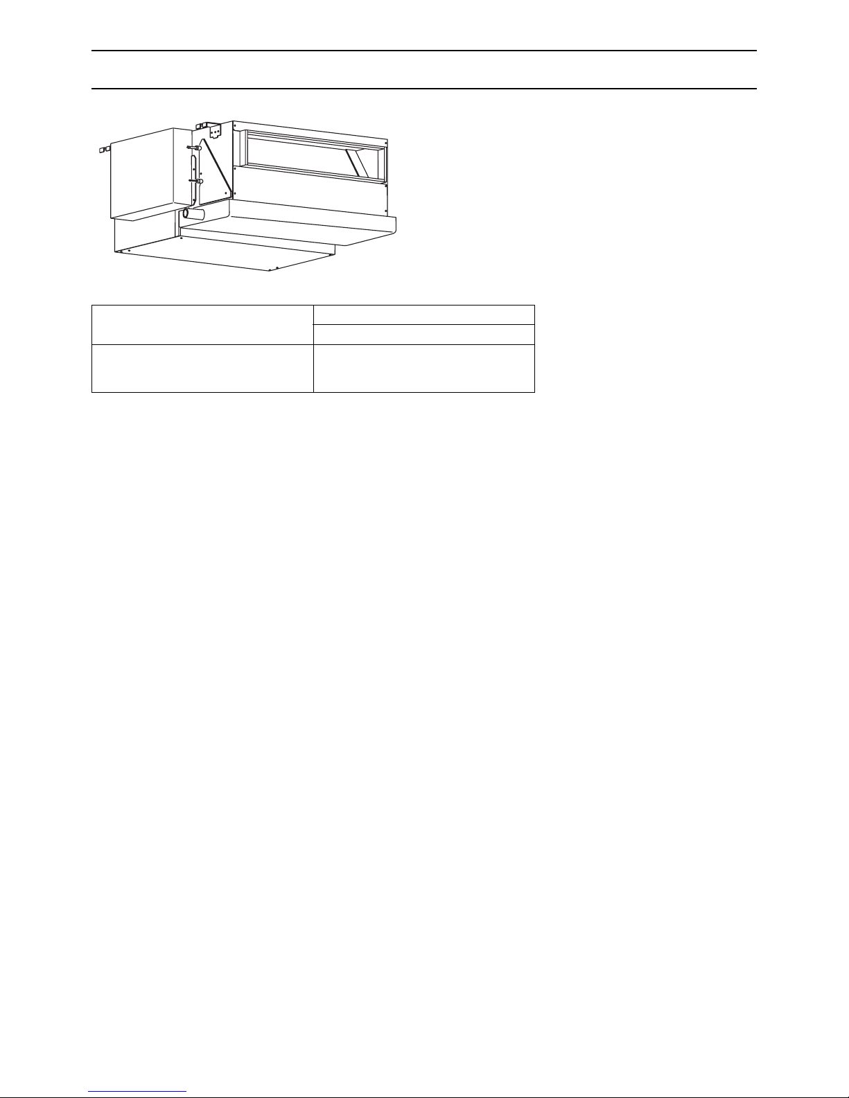
[1] FEATURES
Features......................................................................................................................................... 1
[2] COMPONENTS AND FUNCTIONS
Components and functions......................................... ... .... ... ... ... .... ... ... ... ... .... ... ... ......................... 2
[3] SPECIFICATIONS
3-1. Specifications ...................................................................................................................... 4
3-2. Electrical component specifications..... ... .... ... ... ... .... ... ... ... .... ... ... ... ... ................................... 5
[4] OUTLINES AND DIMENSIONS
PEFY-P20· 25· 32VMR-E-L/R .......................................................................................................6
[5] WIRING DIAGRAM
PEFY-P20· 25· 32VMR-E-L/R .......................................................................................................7
[6] REFRIGERANT SYSTEM DIAGRAM
Refrigerant system diagram........................................................................................................... 9
[7] TROUBLESHOOTING
7-1. Check methods.................................................................................................................. 10
7-2. Address switch setting.......................................................................................................12
7-3. Dipswitch setting (Factory setting).... ... ... .... ... ... ... .... ... ... ... .... ... ... ... ... ................................. 13
7-4. Functions of the LED on the indoor unit service board...................................................... 13
[8] DISASSEMBLY PROCEDURE
8-1. Control box....... ... ... ... .... ... ... ... .... ... .......................................... ... ... ... .... ... .......................... 14
8-2. Fan and fan motor.............................................................................................................15
8-3. Drainpan............................................................................................................................ 16
8-4. LEV, thermistor (Liquid/gas pipe) ...................................................................................... 17
8-5. Heat exchanger............................................. ... ... .... ... ... .......................................... ... ....... 18
8-6. Control box internal layout............................. ... ... .... ... ... ... .... ... ... ... ... .... ... ... ... ....................19
8-7. Thermistor position............................................................................................................ 19
Page 5
- 1 -
[ I FEATURES ]
I FEATURES
[1] FEATURES
Model
Cooling capacity/Heating capacity
kW
PEFY-P20VMR-E-L/R
PEFY-P25VMR-E-L/R
PEFY-P32VMR-E-L/R
2.2/2.5
2.8/3.2
3.6/4.0
Page 6
- 2 -
[ II COMPONENTS AND FUNCTIONS ]
II COMPONENTS AND FUNCTIONS
[2] COMPONENTS AND FUNCTIONS
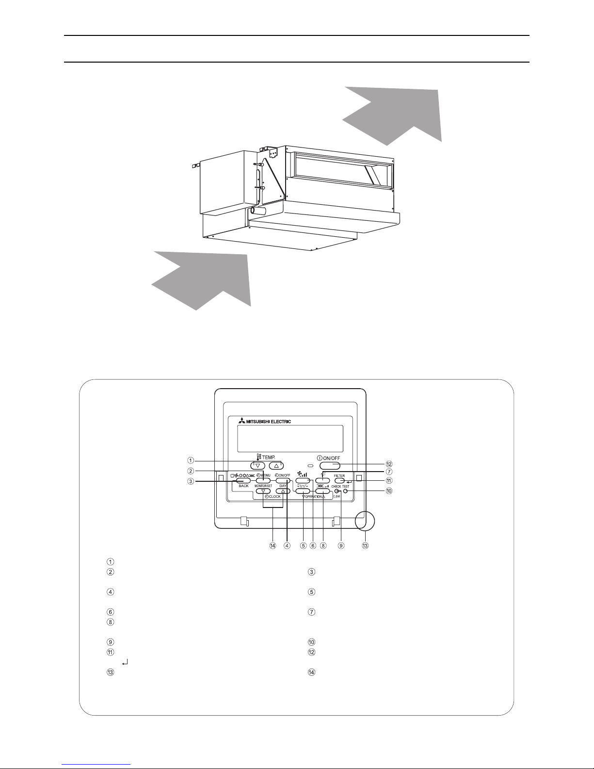
Indoor (Main) Unit
Remote controller
[PAR-21MAA]
Once the operation mode is selected, the unit will remain in the selected mode until
changed.
[Remote Controller Button]
Air
Air
Keep the remote controller out of direct sunlight to ensure accurate measurement of room temperature.
The sensor at the lower right-hand section of the remote controller must be free from obstructions to
ensure accurate measurement of room temperature.
[Set Temperature] Button
[Timer Menu] Button [Mode] Button
[Monitor/Set] Button [Back] Button
[Timer On/Off] Button [Louver] Button
[Set Day] Button [Operation] Button
[Fan Speed] Button [Vane Control] Button
[Ventilation] Button
[Operation] Button
[Check/Clear] Button [Test Run] Button
[Filter] Button [ON/OFF] Button
[ ] Button
Position of built-in room temperature thermistor
[Set Time] Button
Page 7
- 3 -
[ II COMPONENTS AND FUNCTIONS ]
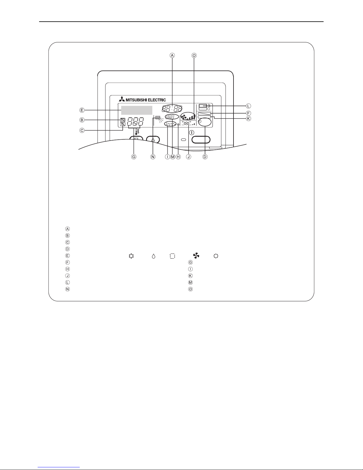
[Remote Controller Display]
ON/OFF
ERROR CODE
TIME
ON
OFFHrAFTER
SUN MON TUE WED THU FRI SAT
TIMER
AFTER
ONLY 1Hr.
°C°F
WEEKLY
SIMPLE
AUTO OFF
FILTER
FUNCTION
°C
°F
TEMP.
Current time/Timer time
Centralized control indicator
Timer OFF indicator
Timer mode
Operation mode display: COOL, DRY, AUTO, FAN, HEAT
Function Lock indicator Preset temperature
Power indicator Louver swing
Ventilation Filter sign
Thermistor position Room temperature
Vane setting Fan speed
Page 8

- 4 -
[ III SPECIFICATIONS ]
III SPECIFICATIONS
[3] SPECIFICATIONS
3-1. Specifications
Model PEFY-P20VMR-E-L/R PEFY-P25VMR-E-L/R PEFY-P32VMR-E-L/R
Cooling capacity *1 kW 2.2 2.8 3.6
Heating capacity *1 kW 2.5 3.2 4.0
Power supply voltage/frequency Single-phase 220/230/24 0 V 50Hz 220/230 V 60Hz
Power consumption
Cooling kW 0.06/0.06 0.07/0.08
Heating kW 0.06/0.06 0.07/0.08
Current consumption
Cooling A 0.29/0.29 0.34/0.38
Heating A 0.29/0.29 0.34/0.38
Settable temperature
range on the remote
controller
Cooling °C (°F) 19 to 30 (67 to 86)
Heating °C (°F) 17 to 28 (63 to 83)
Fan
Type × Quantity Sirocco fan × 1
External static pressure
5
Single-phase induction motor
Motor output kW 0.018 0.023
Driving mechanism Direct-driven
Airflow rate
(Low-Mid-High)
m
3
/min 4.8-5.8-7.9 4.8-5.8-9.3
External finish Galvanized
External dimensions
H × W × D
Rear inlet model
mm 292 × 640 × 580
In. 11-1/2 × 25-1/4 × 22-7/8
Bottom inlet model
mm 300 × 640 × 570
In. 11-7/8 × 25-1/4 × 22-1/2
Net weight kg 18
Wire
Min. wire size mm (in.) 1.6 (1/8)
Breaker amperage A 16
Refrigerant pipe
diameter
Liquid R410A mm (in.) ø6.35 (ø1/4) Brazed connection
Gas R410A mm (in.) ø12.7(ø1/2) Brazed connection
Drain pipe diameter mm (in.) Drain hose O.D. 26 (1-1/32)
Operating noise *2
(Low-Mid-High)
(measured in
anechoic room)
220V dB<A> 20-25-30 20-25-33
230V dB<A> 21-26-32 21-26-35
240V dB<A> 22-27-30 22-27-33
Insulation material Polyethylene foam, Urethane foam
Air filter PP Honeycomb fabric (washable)
Refrigerant control device LEV
Connectable outdoor unit R410A CITY MULTI
Protection devices Fuse
Heat exchanger Cross fin (Aluminium fin and copper tube)
Note:*1 Maximum capacity of the unit under the following conditions
<Cooling> Indoor temperature: 27°CDB/19°CWB (81°FDB/66°FWB Outdoor temperature: 35°CDB (95°FDB)
<Heating> Indoor temperature: 20°CDB (68°FDB) Outdoor temperature: 7°CDB/6°CWB (45°FDB/43°FWB)
Pipe length: 7.5m (24-9/16ft) Height difference: 0m (0ft)
*2 Noise levels of the unit with a rear air inlet. (Noise levels are higher for the unit with a bottom air inlet.)
Page 9

- 5 -
[ III SPECIFICATIONS ]
3-2. Electrical component specifications
Model
Component
Symbol PEFY-P20VMR-E-L/R PEFY-P25VMR-E-L/R PEFY-P32VMR-E-L/R
Transformer T (Primary) 50/60Hz 220-240V (Secondry) (23.5V 0.9A)
Room temperature
thermistor
TH21 Resistance 0°C/15kΩ, 10°C/9.6kΩ, 20°C/6.3kΩ, 25°C/5.4kΩ, 30°C/4.3kΩ, 40°C/3.0kΩ
Liquid pipe
thermistor
TH22 Resistance 0°C/15kΩ, 10°C/9.6kΩ, 20°C/6.3kΩ, 25°C/5.4kΩ, 30°C/4.3kΩ, 40°C/3.0kΩ
Gas pipe thermistor TH23 Resistance 0°C/15kΩ, 10°C/9.6kΩ, 20°C/6.3kΩ, 25°C/5.4k Ω, 30°C/4.3kΩ, 40°C/3.0kΩ
Fuse
(Control board)
F1 250V 6.3A
Fan motor
(with Innerthermostat)
MF 4-pole, Output 18W 4-pole, Output 23W
Inner-thermostat
(Fan motor)
OFF 135°C±5°C ON 86°C±15°C
Fan motor capacitor C1 1.5µF × 440V
Linear expansion
valve
LEV
12VDC Stepping motor drive port diameter ø3.2
(0~1800 pulses <on R410-compatible outdoor units>,
0~2000 pulses <on other types of outdoor units>)
Power supply
terminal block
TB2 (L, N, ) 330V 30A
Transmission
terminal block
TB5 TB15 (1, 2), (M1, M2, S) 300V 10A
Page 10

- 6 -
[ IV OUTLINES AND DIMENSIONS ]
IV OUTLINES AND DIMENSIONS
[4] OUTLINES AND DIMENSIONS
PEFY-P20· 25· 32VMR-E-L/R
2×10-φ3
2×2-
φ3
(In case of bottom inlet)
(In case of rear inlet)
(Suspension bolt pitch)
439
584
80
530
480
105
50×9=450
23
630
50
113
20mm min.
20mm min.
25
5
00
5
0
-
1
5
0
45
0
45
050
- 150
3
00
100
622
250
outlet (Note 1)
(In case of rear inlet)
(In case of bottom inlet)
(Suspension bolt pitch)
Suspension bolt
50 or below
50
15
292
570
300
148
580
62
25
100
30
28
25
275
15
Hard vinyl chloride drainpipe
Drain hose (accessory)
Drain pan
Insulation material
(150)
To be bonded with adhesive
To be gap-free
Hose band
Insulation material
for drain pan
Urethane foam
Right side
Left side
<Pipe size>
Refrigerant pipe (gas,brazed connection) φ12.7 ·········
Refrigerant pipe (liquid,brazed connection) φ6.35 ·········
Drain pipe connection diameter VP20 (dia. 26mm) ·········
Control box
Air outlet
Bottom air inlet
Rear
air inlet
Rear
air inlet
Bottom plate
Terminal block (Power supply)
Terminal block (M-Net Transmission)
Ceiling surface
Access door
1
Suspension bolt hole
Air filter
3
2
(A)
(B)
Note 1. Use M10 suspension bolts. (not supplied)
2. Keep the distance between the bottom end of the suspension bolt on the heat exchanger side and the top panel of the indoor unit to no more than
50 mm to allow easy removal of the panel and access to the indoor unit heat exchanger for maintenance.
3. Provide a 450 mm x 450 mm access door in the ceiling as shown below to allow access to the heat exchanger for cleaning and maintenance.
4. The figures in this drawing show the left-piping specifications. Upside-down mirror images of these figures would show the right-piping specificat ions.
5. Regular cleaning of the drain pan will prevent water overflow.
6. Either the bottom or rear inlet can be used.
7. Leave adequate space between the ceiling and unit when the bottom inlet is used.
(A) Space required for service and maintenance
(Note 2)
(B) Provide an access door as shown in the figure for maint enance.
Page 11

- 7 -
[ V WIRING DIAGRAM ]
V WIRING DIAGRAM
[5] WIRING DIAGRAM
PEFY-P20· 25· 32VMR-E-L/R
PE
S (SHIELD)
INSIDE THE CONTROL BOX
F1
AC250V
6.3A F
( )
SW7
CN3A
3
1
2
1
2
SW12
(10's digit)
SW11
(1's digit)
SW14
(Connection No.)
ZNR1
3
1
CN1
DSA1
S. B
5
4
(White)
2
1
I. B
CN2M
X04X06 X05
X01
CN70
CNP
CND
CNT
CN60
CN31
CN21CN20
CN81
123
4
5
6
1
1
1
1
1
31
12
3
2
2
2
3
31
3
3
4
7
6
71
56
CN52
12345
CN51
12345
CN40
1234
L
N
LEV
MF
TH21 TH22
SW3
SW2
SW1
SWA SWC SW5
M2
M1
1
3
CN3T
A. B
6
5
4
3
2
1
7
8
CN29
1
2
TH23
8
7
1234
123
4
CN42
SW4
(Blue)
CN62
CN82
ZNR
T
65
5
12
3
4
56
7
12
3
4
56
7
12
3
4
56
7
TB15 (TRANSMISSION TERMINAL BLOCK)
TB5 (TRANSMISSION TERMINAL
BLOCK)
8
7
5
6
4
3
2
0
9
1
F
E
D
C
B
A
9
9
0
1
2
3
4
5
6
7
8
0
8
7
6
5
4
3
2
1
TB2
]
C
1.5μF
TO MA REMOTE CONTROLLER
POWER SUPPLY
(A)
- 220,230,240V
50,60Hz
TO DUCT
TO NEXT INDOOR UNIT
PULL BOX
FUSE(16A)
BREAKER(16A)
TO OUTDOOR UNIT
BC CONTROLLER
REMOTE CONTROLLER
PE
Page 12

- 8 -
[ V WIRING DIAGRAM ]
[5] WIRING DIAGRAM
(A)
The fan motor connector is ready for connection to a 220V/230V power supply at factory shipment. Use blue connector adapter
(supplied) to connect to a 240V power supply.
Coler/Power supply voltage
White/220V. 230V
Blue/240V
NOTE: 1. Wiring to TB2, TB5, and TB15 indicated by the dash-double-dotted lines is on-site work.
2. terminal block, connector.
SYMBOL EXPLANATION
SYMBOL NAME SYMBOL NAME
MF Fan motor TH21 Thermistor (inlet temp.)
C Capacity (for MF) 1.5µF TH22 Thermistor (liquid pipe temp.)
I.B Indoor control board TH23 Thermistor (gas pipe temp.)
A.B Address board SW11 (A.B) Switch (For setting the 1’s digit in the address)
TB2 Power supply terminal block SW12 (A.B) Switch (For setting the 10’s digit in the address)
TB5 Transmission terminal block SW14 (A.B) Switch (connection No. setting)
TB15 Transmission terminal block SW1 (A.B) Switch (function setting)
F1 Fuse 250V AC 6.3A F SW2 (A.B) Switch (capacity code setting)
T Transformer SW3 (A.B) Switch (function setting)
LEV Electronic linear expan. valve SW4 (A.B) Switch (model setting)
S.B Surge absorber board SW5 (A.B) Switch (voltage setting)
X04~X06 Aux. relay SW7 (A.B) Switch (function setting)
Page 13

- 9 -
[ VI REFRIGERANT SYSTEM DIAGRAM ]
VI REFRIGERANT SYSTEM DIAGRAM
[6] REFRIGERANT SYSTEM DIAGRAM
Capacity PEFY-P20, 25, 32VMR-E-L/R
Gas pipe ø12.7<1/2>
Liquid pipe ø6.35<1/4>
Gas pipe thermistor TH23
Gas pipe
Brazed connections
Strainer (#100 mesh)
Linear expansion valve
Room temperature thermistor TH21
Heat exchanger
Liquid pipe thermistor
TH22
Page 14

- 10 -
[ VII TROUBLESHOOTING ]
VII TROUBLESHOOTING
[7] TROUBLESHOOTING
7-1. Check methods
1. Component and Check points
(1) Thermistor
• Room temperature thermistor (TH21)
• Liquid pipe thermistor (TH22)
• Gas pipe thermistor (TH23)
Disconnect the connector, and measure the resistance with a tester.
(Ambient temperature 10°C-30°C)
(Refer to the thermistor characteristic graph below.)
(2) Transformer
Disconnect the connector, and measure the resistance with a tester.
(3) Fan motor PEFY-P20· 25· 32
Measure the resistance between the terminals with a tester. (at 20°C)
Normal Abnormal
4.3kΩ-9.6kΩ Open or short
Normal Abnormal
CNT(1)-(3) Approx.15Ω
Open or short
CN3T(1)-(3) Approx. 4Ω
Motor terminal
or
Relay connector
Normal
Abnormal
P20· 25 P32
White-Black 192Ω 164Ω
Open or short
White-Brown 214Ω 185Ω
White-Yellow 236Ω 227Ω
White-Blue 272Ω 257Ω
White-Red 376Ω 355Ω
Yellow/Green
RedOrange
Blue
Yellow
Brown
Black
White
220~240V
50/60Hz
Page 15

- 11 -
[ VII TROUBLESHOOTING ]
(4) Linear expansion valve
Disconnect the connector, and measure the resistance with a tester.
<Thermistor characteristic graph>
Room temperature thermistor (TH21)
Liquid pipe thermistor (TH22)
Gas pipe thermistor (TH23)
Thermistor R
0
=15kΩ ±3%
Multiplier of B=3480kΩ ±2%
0°C 15kΩ
10°C 9.6kΩ
20°C 6.3kΩ
25°C 5.2kΩ
30°C 4.3kΩ
40°C 3.0kΩ
Normal Abnormal
(1)-(5)
White-Red
(2)-(6)
Yellow-Brown
(3)-(5)
Orange-Red
(4)-(6)
Blue-Brown
Open or short
150Ω ±10%
White
Yellow
Orange
Blue
Red
Brown
Resistance (kΩ)
Temperature (°C)
Rt=15exp {3480(
-
)}
1
273+t1273
Page 16

- 12 -
[ VII TROUBLESHOOTING ]
7-2. Address switch setting
1) When using an ME remote controller, set the address with the rotary switches (SW11, SW12).
* Address setting is not required when the unit remote controller is used.
2) Address settings vary in different systems.
Refer to the section on address setting in the outdoor unit installation manual.
3) Address is set with a combination of SW12 (10's digit) and SW11 (1's digit).
To set the address to "3," set SW12 to "0" and SW11 to "3."
To set the address to "25," set SW12 to "2" and SW11 to "5."
Make sure that power to the unit is turned off.
12345678910
123 54
Indoor unit control board
ON
OFF
ON
OFF
<Factory setting (All models)>
<Factory setting (All models)>
Refer to the next page for setting dipswitches SW2 and
SW3.
On-site address setting is required for the indoor units to run.
Page 17

- 13 -
[ VII TROUBLESHOOTING ]
7-3. Dipswitch setting (Factory setting)
7-4. Functions of the LED on the indoor unit service board
Symbol Printing: Silk printing Normal LED display
LED1 Main power supply When a voltage of 220-240 is applied to the indoor unit board → Lit
LED2 Transmission power supply When the MA remote controller is powered → Lit
PEFY-P32VMR-E-R
PEFY-P25VMR-E-R
PEFY-P20VMR-E-R
PEFY-P32VMR-E-L
PEFY-P25VMR-E-L
PEFY-P20VMR-E-L
G01
G02
G03
SW1 SW2 SW3
SW7SW4
SWC
SWA
SW5
12345678910
12345678910
220 V
240 V
220 V
240 V
220 V
240 V
1
111
2
1
11
1
3
1
1
1112
222
4
2
22
2
5
2
2
22
333
6
3
33
3
7
3
3
333
4544
8
4
454
4
9
544
55
10
5
5
55
66
6
6
66
77788899910
1010
3
3
3
2
2
2
1
1
1
Group No. Models
Option
Standard
Option
Standard
Option
Standard
ON
ON
ON
ON
ON
ON
ON
ON
ON
ON
ON
ON
ON
ON
ON
Page 18

- 14 -
[ VIII DISASSEMBLY PROCEDURE ]
VIII DISASSEMBLY PROCEDURE
[8] DISASSEMBLY PROCEDURE
8-1. Control box
1. Removing the control box cover
Remove the two fixing screws on the control box, and remove the
cover. (Fig. 1)
* The following services can be performed with the cover
removed. (Fig. 2)
Functions of the switches on the control board.
• Dip switch SW2......................Capacity code setting
• Dip switch SW3......................Function setting
• Dip switch SW4......................Model setting
Functions of the switches on the address board.
• Rotary switches SW11, 12.....Address setting
• Rotary switch SW14 ..............Connection No. setting
• Dip switch SW1......................Function setting (main)
Lead wires that are connected with the control box below can
be checked.
• Power supply lead wire
• Network remote contoller transmission wire
• Fan motor lead wire
• LEV lead wire
• Intake air thermistor lead wire
• Liquid pipe thermistor lead wire
• Gas pipe thermistor lead wire
• Power supply transformer lead wire
• Address board lead wire
Control board replacement
Address board replacement
Capacitor replacement
Power supply transformer replacement
Arrestor replacement
Intake air thermistor replacement
Power supply terminal block replacement
Transmission terminal block replacement
Exercise caution when removing heavy parts.
Control box
Fig. 1
Fig. 2
Note: Refer to "8-6. Control box internal layout" (P19) for the
positions of switches on the controller board and address
board.
Page 19

- 15 -
[ VIII DISASSEMBLY PROCEDURE ]
8-2. Fan and fan motor
1. Removing the fan casing, sirocco fan, and fan motor
(1) Remove the filter. (Fig. 3)
(2) Open the control box to remove the fan motor cable
connector.
(Unscrew the two fixing screws if it is difficult to remove the
connector.) (Fig. 4)
(3) Squeeze the four tabs on the fan casing to remove it. (Fig. 5)
(4) Remove the set screw on the sirocco fan and the two motor
set screws to remove the sirocco fan and fan motor. (Fig. 6)
Exercise caution when removing heavy parts.
Filter
Fig. 3
Fig. 4
Fan motor cable connector
Fig. 5
Fan casing
Fig. 6
Set screw
Page 20

- 16 -
[ VIII DISASSEMBLY PROCEDURE ]
8-3. Drainpan
1. Removing the drainpan
(1) Remove the one fixing screw on the drainpan. (Fig. 7)
(2) Slide the drainpan in the order as indicated with arrows ,
, and to remove the drainpan. (Fig. 8)
Exercise caution when removing heavy parts.
Fig. 7
Fig. 8
Page 21

- 17 -
[ VIII DISASSEMBLY PROCEDURE ]
8-4. LEV, thermistor (Liquid/gas pipe)
1. Removing the LEV
(1) Remove the drainpan according to the procedure in section
8-3.
(2) Remove the bottom plate by unscrewing the six fixing
screws. (Fig. 9)
(3) Remove the LEV driving motor using two spanners. (Fig. 10)
2. Removing the thermistors
(1) Remove the thermistors from the thermistor holders on the
piping. (Fig. 11)
(Liquid piping: small diameter; Gas piping: large diameter)
Exercise caution when removing heavy parts.
Fig. 9
LEV
Fig. 10
Thermistor
Fig. 11
Page 22

- 18 -
[ VIII DISASSEMBLY PROCEDURE ]
8-5. Heat exchanger
1. Removing the heat exchanger
(1) Remove the drainpan according to the procedure in section
8-3.
(2) Remove the bottom plate according to the procedure in
section 8-4.
(3) Remove the heat exchanger cover by unscrewing the five
fixing screws. (Fig. 12)
(4) Remove the heat exchanger by unscrewing the two fixing
screws. (Fig. 13)
Exercise caution when removing heavy parts.
Heat exchanger
cover
Fig. 12
Fig. 13
Page 23

- 19 -
[ VIII DISASSEMBLY PROCEDURE ]
8-6. Control box internal layout
8-7. Thermistor position
LN
SW2 SW3 SW4
CN31
CN60
CN29
CN21
CN20
CN2M
CN3A
CN3T
CND
CNT
CN70
CN42
CN81
SW14
SW5SWCSWA
SW12 SW11
SW7
MA Remo.Con.
CAUTION
Transmission.
M-NET Remo.Con.
TB5
TB15
12
M1
M2
S
Never connect
Power
supply
Power
supply
EARTH
N
L
Connector
adapter
Secondary
Transformer
Power supply
terminal block
DSA board
Transmission
terminal block
Capacitor (for motor)
Indoor unit control board
PrimaryAddress board
Fan motor connector
Gas thermistor
Liquid thermistor
Page 24

Oct. 2006 HWE06010
Printed in Japan
New publication, effective Oct. 2006
Specifications subject to change without notice
 Loading...