

Mitsubishi PEFY-P20VMM-E, PEFY-P25VMM-E, PEFY-P32VMM-E, PEFY-P40VMM-E, PEFY-P50VMM-E Service Manual
...Page 1
TECHNICAL & SERVICE MANUAL
Air-Conditioners For Building Application
<Indoor unit>
PEFY-P20VMM-E,PEFY-P71VMM-E
PEFY-P25VMM-E,PEFY-P80VMM-E
PEFY-P32VMM-E,PEFY-P100VMM-E
PEFY-P40VMM-E,PEFY-P125VMM-E
PEFY-P50VMM-E,PEFY-P140VMM-E
PEFY-P63VMM-E
2004
Models
INDOOR UNIT
Ceiling Concealed
Series PEFY
CONTENTS
SAFETY PRECAUTIONS ·························1
1. FEATURES············································3
2. PART NAMES AND FUNCTIONS ········4
3. SPECIFICATION ···································6
4. OUTLINES AND DIMENSIONS············8
5. WIRING DIAGRAM ·····························10
6.
REFRIGERANT SYSTEM DIAGRAM
····12
7. TROUBLE SHOOTING························13
8. DISASSEMBLY PROCEDURE···········18
For use with R410A & R407C & R22
Page 2
SAFETY PRECAUTIONS
- Inadequate connection and fastening may generate heat and
cause a fire.
• Prepare for typhoons and other strong winds and earthquakes
and install the unit at the specified place.
- Improper installation may cause the unit to topple and result in
injury.
• Always use an air cleaner, humidifier, electric heater, and other
accessories specified by Mitsubishi Electric.
- Ask an authorized technician to install the accessories. Improper
installation by the user may result in water leakage, electric shock,
or fire.
• Never repair the unit. If the air conditioner must be repaired,
consult the dealer.
- If the unit is repaired improperly, water leakage, electric shock, or
fire may result.
• Do not touch the heat exchanger fins.
- Improper handling may result in injury.
• If refrigerant gas leaks during installation work, ventilate the
room.
- If the refrigerant gas comes into contact with a flame, poisonous
gases will be released.
• Install the air conditioner according to this Installation Manual.
- If the unit is installed improperly, water leakage, electric shock, or
fire may result.
• Have all electric work done by a licensed electrician according
to “Electric Facility Engineering Standard” and “Interior Wire
Regulations”and the instructions given in this manual and always use a separate circuit.
- If the power source capacity is inadequate or electric work is per-
formed improperly, electric shock and fire may result.
• Securely install the cover of control box and the panel.
- If the cover and panel are not installed properly,dust or water may
enter the outdoor unit and fire or electric shock may result.
• Keep the electric parts away from water (washing water etc.).
- It might result in electric shock, catching fire or smoke.
• When installing and moving the air conditioner to another site,
do not charge it with a refrigerant differen t from the refrigerant specified on the unit.
- If a different refrigerant or air is mixed with the original refrigerant,
the refrigerant cycle may malfunction and the unit may be damaged.
• If the air conditioner is installed in a small room, measures
must be taken to prevent the refrigerant concentration from
exceeding the safety limit even if the refrigerant should leak.
- Consult the dealer regarding the appropriate measures to pre-
vent the safety limit from being exceeded. Should the refrigerant
leak and cause the safety limit to be exceeded, hazards due to
lack of oxygen in the room could result.
• When moving and reinstalling the air conditioner, consult the
dealer or an authorized technician.
- If the air conditioner is installed improperly, water leakage, elec-
tric shock, or fire may result.
• After completing installation work, make sure that refrigerant
gas is not leaking.
- If the refrigerant gas leaks and is exposed to a fan heater, stove,
oven, or other heat source, it may generate noxious gases.
• To dispose of this product, consult your dealer.
• Do not use a leak detection additive.
• Do
devices.
not reconstruct or change the settings of the protection
- If the pressure switch, thermal switch, or other protection device
is shorted and operated forcibly, or parts other than those specified
by Mitsubishi Electric are used, fire or explosion may result.
1. Before installation and electric work
s Before installing the unit, make sure you read all the
“Safety precautions”.
s The “Safety precautions” provide very important
points regarding safety. Make sure you follow them.
s This equipment may not be applicable to EN61000-3-
2: 1995 and EN61000-3-3: 1995.
s This equipment may cause the adverse effect on the
same supply system.
s Please report to or take consent by the supply au-
thority before connection to the system.
Symbols used in the text
Warning:
Describes precautions that should be observed to prevent danger
of injury or death to the user.
Caution:
Describes precautions that should be observed to prevent damage
to the unit.
Symbols used in the illustrations
: Indicates an action that must be avoided.
: Indicates that impor tant instructions must be followed.
: Indicates a part which must be grounded.
: Indicates that caution should be taken with rotating par ts. (This
symbol is displayed on the main unit label.) <Color: Yellow>
: Beware of electric shock (This symbol is displayed on the main
unit label.) <Color: Yellow>
Warning:
Carefully read the labels affixed to the main unit.
Warning:
• Ask the dealer or an authorized technician to install the air conditioner.
- Improper installation by the user may result in water leakage, elec-
tric shock, or fire.
• Install the air unit at a place that can withstand its weight.
- Inadequate strength may cause the unit to fall down, resulting in
injuries.
• Use the specified cables for wiring. Make the connections securely so that the outside force of the cable is not applied to the
terminals.
1
Page 3

2. Precautions for devices that use
R410A or R407C refrigerant
Caution:
• Do not use the existing refrigerant piping.
- The old refrigerant and refrigerator oil in the existing piping contains a large amount of chlorine which may cause the refrigerator
oil of the new unit to deteriorate.
• Use refrigerant piping made of phosphorus
per.
deoxidized cop-
In addition, be sure
that the inner and outer surfaces
of the pipes are clean and
free of hazardous sulphur, oxides,
dust/dirt, shaving particles,
minant.
oils, moisture, or any other conta-
- Contaminants on the inside of the refrigerant piping may cause
the refrigerant residual oil to deteriorate.
• Store the piping to be used during installation indoors and keep
both ends of the piping sealed until just before brazing. (Store
elbows and other joints in a plastic bag.)
- If dust, dirt, or water enters the refrigerant cycle, deterioration of
the oil and compressor trouble may result.
• Use ester oil, ether oil or alkylbenzene (small amount) as the
refrigerator oil to coat flares and flange connections.
- The refrigerator oil will degrade if it is mixed with a large amount of
mineral oil.
• Use liquid refrigerant to fill the system.
- If gas refrigerant is used to seal the system, the composition of
the refrigerant in the cylinder will change and performance may
drop.
• Do not use a refrigerant other than R410A or R407C.
- If another refrigerant (R22, etc.) is used, the chlorine in the refrig-
erant may cause the refrigerator oil to deteriorate.
• Use a vacuum pump with a reverse flow check valve.
- The vacuum pump oil may flow back into the refrigerant cycle and
cause the refrigerator oil to deteriorate.
• Do not use the following tools that are used with conventional
refrigerants.
(Gauge manifold, charge hose, gas leak detector, reverse flow
check valve, refrigerant charge base, vacuum gauge, refrigerant recovery equipment.)
- If the conventional refrigerant and refrigerator oil are mixed in the
R410A or R407C, the refrigerant may deteriorated.
- If
deteriorate.
water is mixed in the R410A or R407C, the refrigerator oil may
- Since R410A or R407C does not contain any chlorine, gas leak
detectors for conventional refrigerants will not react to it.
• Do not use a charging cylinder.
- Using a charging cylinder may cause the refrigerant to deteriorate.
• Be especially careful when managing the tools.
- If dust, dirt, or water gets in the refrigerant cycle, the refrigerant
may deteriorate.
2
Page 4
PEFY-P20VMM-E
PEFY-P25VMM-E
PEFY-P32VMM-E
PEFY-P40VMM-E
PEFY-P50VMM-E
PEFY-P63VMM-E
PEFY-P71VMM-E
PEFY-P80VMM-E
PEFY-P100VMM-E
PEFY-P125VMM-E
PEFY-P140VMM-E
2.2/ 2.5
2.8/ 3.2
3.6/ 4.0
4.5/ 5.0
5.6/ 6.3
7.1/ 8.0
8.0/ 9.0
9.0/ 10.0
11.2/ 12.5
14.0/ 16.0
16.0/ 18.0
FEATURES
1
Indoor unit
Ceiling Concealed
Series PEFY
Models
Cooling capacity/Heating capacity
kW
3
Page 5
PART NAMES AND FUNCTIONS
2
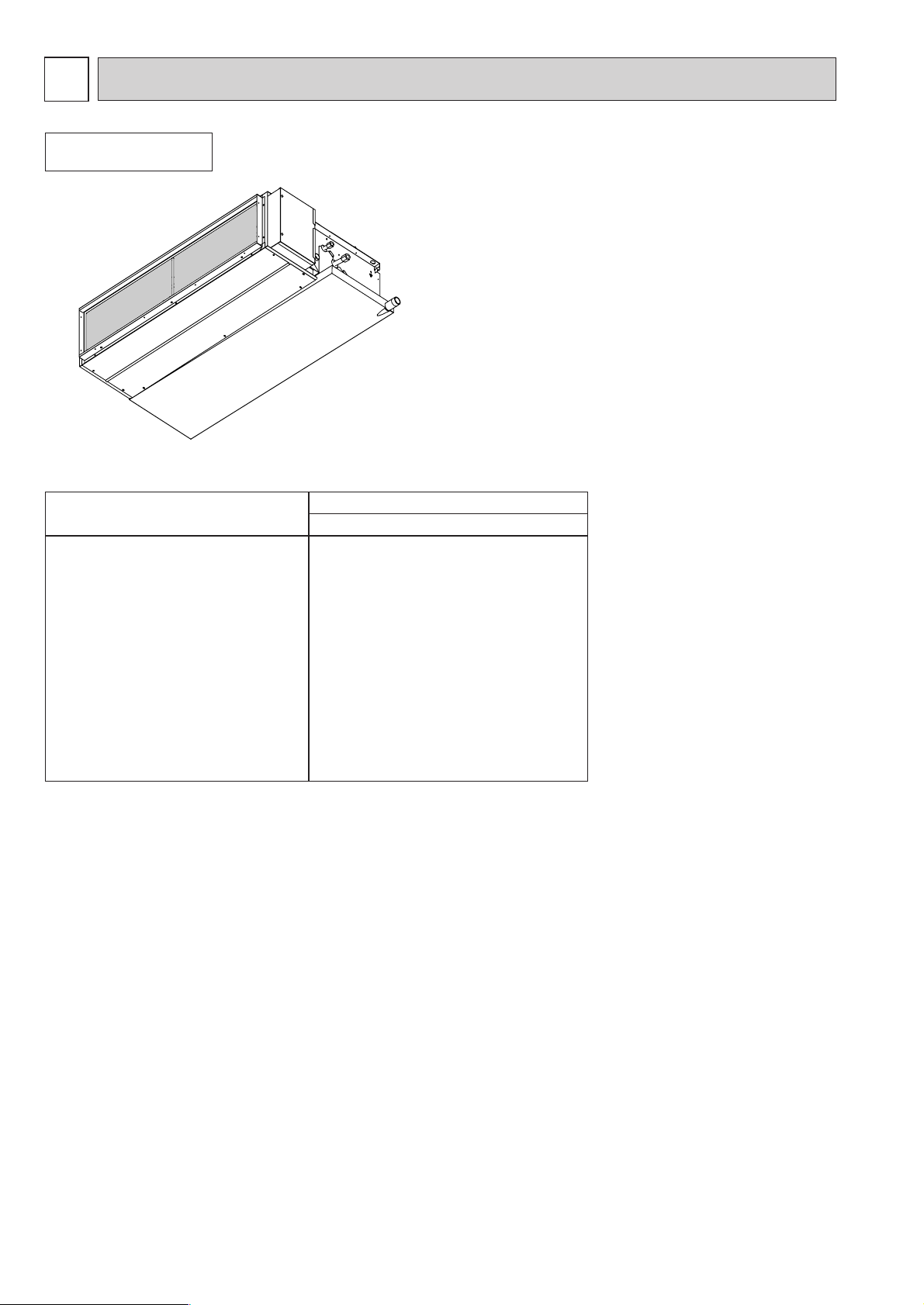
● Indoor (Main) Unit
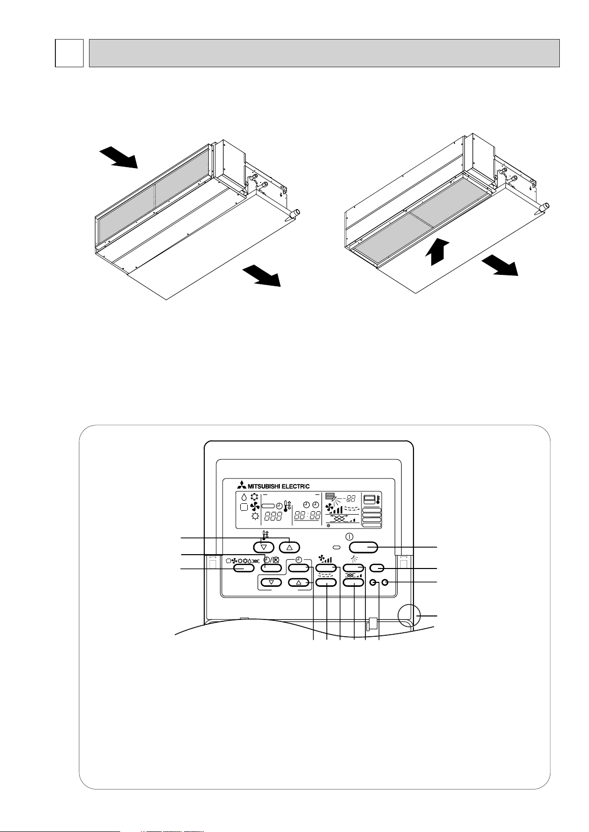
● Remote controller
● Operation buttons
[PAR-20MAA]
●
PAR-20MAA
ON/OFF
CENTRALLY CONTROLLED
ERROR CODE
CLOCK
ON OFF
˚C
CHECK
CHECK MODE
FILTER
TEST RUN
FUNCTION
˚C
1Hr.
NOT AVAILABLE
STAND BY
DEFROST
FILTER
CHECK TEST
TEMP.
TIMER SET
1
2
3
456879
0
C
A
B
Air inlet
Air outlet
1 [Room temperature adjustment] Button
2 [Timer/continuous] Button
3 [Selecting operation] Button
4 [Time selection] Button
[Time-setting] Button
5 [Louver] Button
6 [Fan speed adjustment] Button
Air inlet
Air outlet
[In case of rear inlet]
[In case of bottom inlet]
7 [Up/down airflow direction] Button
8 [Ventilation] Button
9 [Checking/built-in] Button
0 [Test run] Button
A [Filter] Button
B [ON/OFF] Button
C Position of built-in room temperature sensor
•
•
Once the controls are set, the same operation mode can be
repeated by simply pressing the ON/OFF button.
Never expose the remote controller to direct sunlight. Doing so can result in the erroneous measurement of room temperature.
Never replace any obstacle around the lower right-hand section of the remote controller. Doing so can
result in the erroneous measurement of room temperature.
4
Page 6
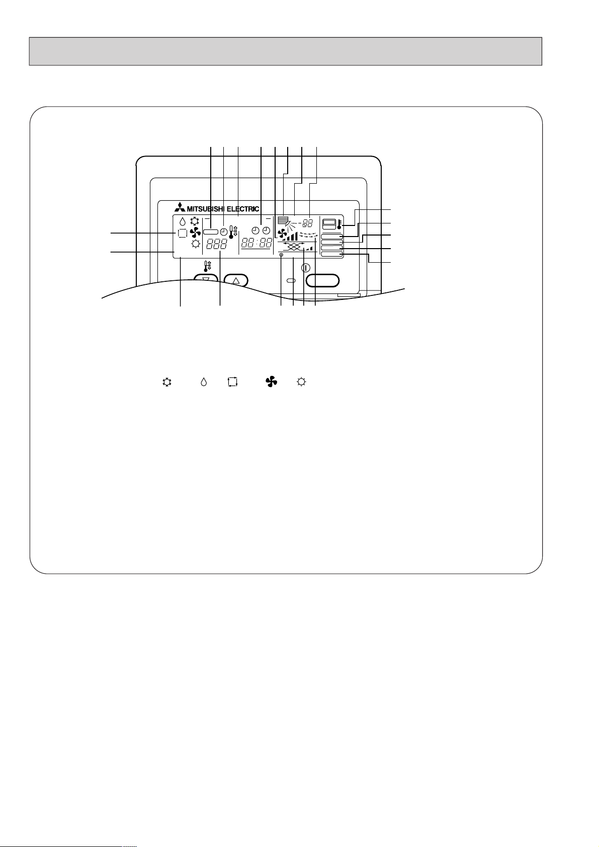
● Display
(A) Current time/Timer
(B) Centralized control
(C) Timer ON
(D) Abnormality occurs
(E) Operation mode: COOL, DRY, AU TO, FAN, HEAT
(F) Preparing for Heating mode
(G) Defrost mode
(H)
Set temperature
(I) Power ON
(J) Louver
(K) Not available function
(L) Ventilation
(M) Function setting mode
(N) Test run mode
(O) Error check mode
(P) Filter sign
(Q)
Set effective for 1 hr.
(R) Sensor position
(S) Room temperature
(T) Airflow
(U) Fan speed
5
E
F
STAND BY
DEFROST
G
ABCD
CENTRALLY CONTROLLED
CHECK
TEMP.
˚C
ON OFF
CLOCK
ERROR CODE
HIKLJ
1Hr.
NOT AVAILABLE
SQTU
˚C
CHECK MODE
ON/OFF
FILTER
TEST RUN
FUNCTION
R
P
O
N
M
Page 7
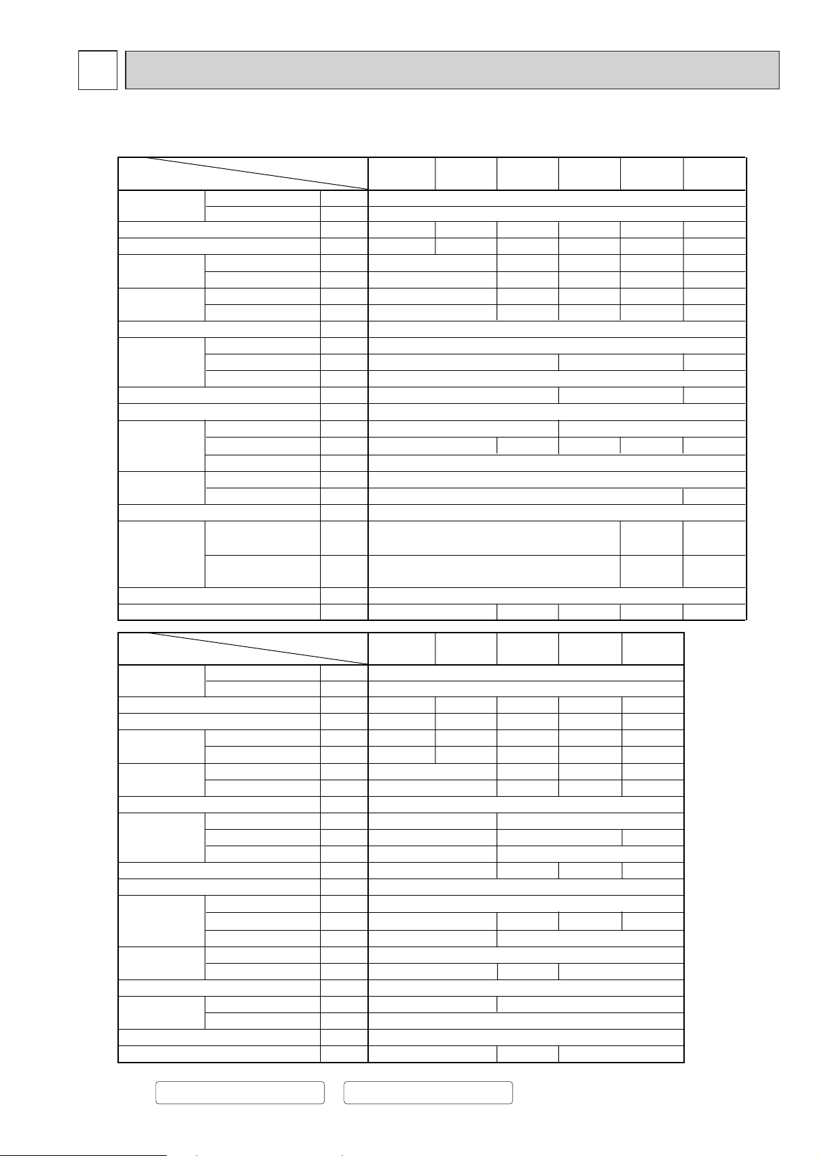
3
SPECIFICATION
3-1. Specification
Note: 1.Cooling / Heating capacity indicates the maximum value at operation under the following condition.
Cooling :Indoor 27°CDB/19.0°CWB Heating
:Indoor 20°C
:Outdoor 35
°CDB :Outdoor 7°CDB/6°CWB
2.The external static pressure is set to 50Pa at factory shipment.
0.078
0.078
220-240
50
Galvanized steel plate
325
740
Cross fin( Alminium plate fin and copper tube)
Single phase induction motor
P.P. honeycomb
ø9.52
R1(External thread)
Power source
Model
PEFY-P20
VMM-E
PEFY-P25
VMM-E
PEFY-P32
VMM-E
PEFY-P40
VMM-E
PEFY-P50
VMM-E
Item
Dimension
Fan
Motor
Refrigerant
pipe dimension
Power consumption
Current
Cooling capacity
Heating capacity
External finish
Net weight
Heat exchanger
Air filter
Drain pipe dimension
Noise level
(Low-[Middle]-High)
Voltage
Frequency
Cooling
Heating
Cooling
Heating
Height
Width
Depth
Type
External static pressure
Type
Output
Gas(Flare)
Liquid(Flare)
~V
Hz
kW
kW
kW
kW
A
A
mm
mm
mm
kg
m3/min
Pa
kW
mm
mm
dB
220-240
50
3.6
4.0
0.17
0.17
0.81
0.81
Galvanized steel plate
295
700
Cross fin( Alminium plate fin and copper tube)
7.5-9.0-10.5
30/50/100
Single phase induction motor
0.075
R1(External thread)
4.5
5.0
5.6
6.3
2.2
2.5
2.8
3.2
0.15
0.15
0.73
0.73
815
Note:1
Note:1
Note:1
Note:1
Note:2
Note:2
27
Sirocco fan ✕
1
6.0-7.2-8.5 10.0-12.0-14.0 12.0-14.5-17.0
Sirocco fan ✕
2
33
295
700
935
Airflow rate
(Low-[Middle]-High)
Power source
Model
PEFY-P71
VMM-E
PEFY-P63
VMM-E
PEFY-P80
VMM-E
PEFY-P100
VMM-E
PEFY-P125
VMM-E
Item
Dimension
Fan
Motor
Refrigerant
pipe dimension
Power consumption
Current
Cooling capacity
Heating capacity
External finish
Net weight
Heat exchanger
Air filter
Drain pipe dimension
Noise level
(Low-[Middle]-High)
Voltage
Frequency
Cooling
Heating
Cooling
Heating
Height
Width
Depth
Type
External static pressure
Type
Output
Gas(Flare)
Liquid(Flare)
~V
Hz
kW
kW
kW
kW
A
A
mm
mm
mm
kg
m3/min
Pa
kW
mm
mm
dB
11.2
12.5
0.29
0.29
1.34
1.34
14.0
16.0
0.40
0.40
1.90
1.90
8.0
9.0
0.25
0.25
7.1
8.0
0.22
0.22
1.07
1.07
9.0
10.0
0.25
0.25
1.15
1.15
1,175
42
1,175
42
0.200
Sirocco fan ✕
2
14.5-18.0-21.0
13.5-16.2-19.0
28.0-40.0
23.0-33.0
30/50/100 50/130
62 65
1,415 1,715
ø15.88 ø15.88(R410A), ø19.05(R22,R407C)
32-36-39
31-35-38
40-44 42-45
PEFY-P140
VMM-E
16.0
18.0
0.42
0.42
1.95
1.95
0.280
29.5-42.0
70
31-34-37 31-35-3828-32-3527-30-32
0.19
0.19
0.92
0.92
0.20
0.20
0.98
0.98
ø12.7
ø6.35
ø15.88
ø9.52
Airflow rate
(Low-[Middle]-High)
P.P. honeycomb
ø
12.7(R410A)
ø
15.88(R22,R407C)
ø
6.35(R410A)
ø
9.52(R22,R407C)
6
Page 8
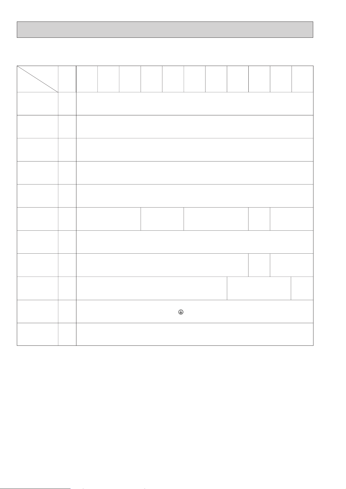
3-2. Electrical parts specifications
7
Model
Parts
name
Transformer T (Primary) 50/60Hz 220-240V (Secondry) (18.4V 1.7A)
Room
temperature
ther mistor
Liquid pipe
ther mistor
Gas pipe
ther mistor
Fuse
(Indoor con -
troller board)
Fan motor
(with Inner-
ther mostat)
Innerthermostat
(Fan motor)
Symbol
MF1,2
PEFY-P20
VMM-E
TH21 Resistance 0˚C/15k
TH22 Resistance 0˚C/15k
TH23 Resistance 0˚C/15kΩ ,10˚C/9.6kΩ ,20˚C/6.3kΩ ,25˚C/5.4kΩ ,30˚C/4.3kΩ ,40˚C/3.0kΩ
FUSE 250V 6.3A
PEFY-P25
VMM-E
4-pole Output 75W
D104P75MW
PEFY-P32
VMM-E
PEFY-P40
VMM-E
PEFY-P50
VMM-E
PEFY-P63
VMM-E
PEFY-P71
VMM-E
PEFY-P80
VMM-E
Ω ,10˚C/9.6kΩ ,20˚C/6.3kΩ ,25˚C/5.4kΩ ,30˚C/4.3kΩ ,40˚C/3.0kΩ
Ω ,10˚C/9.6kΩ ,20˚C/6.3kΩ ,25˚C/5.4kΩ ,30˚C/4.3kΩ ,40˚C/3.0kΩ
4-pole
Output 75W
D104P85MW
OFF 130˚C ± 5
ON 90˚C ± 20
4-pole Output 78W
D10CP95MW
PEFY-P100
NS-100VM-1
VMM-E
4-pole
Output
200W
PEFY-P125
VMM-E
4-pole
Output
280W
NS-125VM-1
PEFY-P140
VMM-E
an motor
F
capacitor
Linear
expansion valve
Power supply
terminal bed
Transmission
terminal bed
C1
LEV
TB2 (L,N, ) 330V 30A
TB5
TB15
DC12V Stepping motor drive port
dimension ø3.2 (0~2000pulse)
6.0µF X 440V X 1pcs
(M1,M2,S)
(1,2)
300V 10A
8.0µF X 440V
X 1pcs
DC12V Stepping motor drive
port dimension ø 5.2
(0
16µF X 440V
X 2pcs
Stepping motor drive
~2000pulse)
por t dimension ø6.4
DC12V
(0~2000pulse)
Page 9

4
OUTLINES AND DIMENSIONS
Indoor Unit PEFY-P20•25•32•40•50•63•71•80VMM-E
Unit : mm
8
C B
176
10
81
A
81
256
40
10
15
7
7
4
1
2
6
5
3
85
29
22761
81
A
E 13
13
282
45
80
277
21
30
640 30
24
35
10
179
109
10
3.5
3.5
256
288
40
176
Set
450
450
A
C B 81
10
C
30D
10-ø3(P20,25,32,40,50)
12-ø3(P63,71,80)
10-ø3(P20,25,32,40,50)
12-ø3(P63,71,80)
10-ø3(P20,25,32,40,50)
12-ø3(P63,71,80)
In case of bottom inlet
In case of rear inlet
(14✕22)
Lifting bolt hole
Air inlet
Air outlet
243
159
35556
10
81B
365~465
18
44 75
1234567
Refrigerant piping flare connection (liquid øF copper tube) :HP
Refrigerant piping flare connection (gas øG copper tube) :LP
Drain R1(External thread)
Electrical parts box
Drain Pump (Option)
Drain Pipe (Option)
• • • Flexible joint VP-25(I.D.ø32)
Filter
Keep duct-work length 850mm or more.
Be sure to apply the air filter near the air inlet grille.
Service space:500 or more
197
8155
Access door
Air outlet
Air inlet
12.76.35✻1 ✻1
804830305772
P50
12.7
12.76.35
6.35
G
15.88
F
9.52
✻2
✻2
684710245
---
652
P20,25,32
P40
Model
772 305 830 804
15.889.52
P63,71,80
1012
280 290
1070 1044
ABCDE
50~150
✻1:R410A outdoor unit
✻2:The other outdoor unit
Page 10

Indoor Unit PEFY-P100•125•140VMM-E
Unit : mm
9
29
C B 81
10
81
A
40
1811027915
30
282
Set
210
450
450
140
282
680
3
3
30
7
4
1
2
319
279
181
40
25
A
C B 81
10
375
10
80
C B 81AE 13
30D
20
35
30
10
53
169
In case of bottom inlet
In case of rear inlet
113
307
122
Lifting bolt hole
45
Air inlet
Air outlet
44
243
308
323
75
13
1
2
34576
Refrigerant piping flare connection (liquid ø9.52 copper tube) :HP
Refrigerant piping flare connection (gas ø15.88 <R410A outdoor unit > copper tube):LP
ø19.05 <R22 or R407C outdoor unit >
Drain R1 (External thread)
Electrical parts box
Drain Pump (Option)
Drain Pipe (Option)
• • • Flexible joint VP25(I.D.ø32)
Filter
Keep duct-work length 850mm or more.
Be sure to apply the air filter near the air inlet grille.
Service space:500 or more
81
197
8155
Access door
Air outlet
Air inlet
15841610
470460
1552
P140
EDCBA
12841310
370360
1252
Model
P100 • 125
12-
ø3
12-ø3
12-ø3
(14✕22)
365~465
50~150
6
5
3
7
Page 11

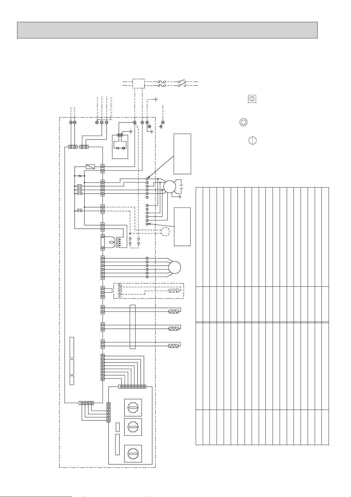
5
WIRING DIAGRAM
Indoor Unit PEFY-P20•25•32•40•50•63•71•80VMM-E
10
Thermistor (piping temp.detection/liquid)
Thermistor (piping temp.detection/gas)
Connector (Vane)
Switch (for mode selection)
Switch (for capacity code)
Switch (2nd digit address set)
Switch (connection No.set)
Switch (for mode selection)
MODELS 20/25/32/40/50/63/71/80 6µF X 1pcs
Switch (for model selection)
Ferrite core
Switch (for voltage selection)
DP
Drain pump
Drain sensor
DS
87654321
(Black)
(White)(Red)
(White)
1
423
(White)
POWER SUPPLY
~/N 220-240V 50Hz
TO DUCT
TO NEXT INDOOR UNIT
PULL BOX
FUSE(16A)
BREAKER(16A)
TO OUTDOOR UNIT
BC CONTROLLER
M-NET REMOTE
CONTROLLER
56
TO MA REMOTE CONTROLLER
SYMBOL SYMBOL
MF
C
I.B.
A.B.
F
T
LEV
Fan motor
✻Capacitor(for MF)
✻Capacitor
Electronic linear expan. valve
Indoor controller board
Address board
Transformer
Thermistor (inlet temp.detection)
Switch (1st digit address set)
SW2(I.B.)
SW3(I.B.)
TH21
TH22
TH23
CNV
SW11(A.B.)
SW12(A.B.)
SW14(A.B.)
SW1(A.B.)
SW4(I.B.)
TB2
TB5 Transmission terminal bed
Power source terminal bed
Fuse AC250V 6.3A F
FB1,2
SYMBOL EXPLANATION
NAME NAME
Surge absorber boardS.B.
Connector (Heater)
Connector (Humidifier)
Connector (Remote switch)
CN51
Connector (Centrally control)
Connector (Remote indication)
CN52
Connector (Vane)
CN23
CN24
CN25
Connector (Damper)
CN27
CN32
Connector (HA Terminal-A)CN41
Switch (option parts)SWA(A.B.)
SWC(A.B.) Switch (option parts)
SW5(A.B.)
TB15 Transmission terminal bed
0
0
9
8
7
6
2
1
9
8
7
6
5
4
3
2
1
1
2
3
4
5
6
7
8
9
0
5
4
3
F
E
D
C
B
A
TB2
TB5(TRANSMISSION TERMINAL BED)
TB15(TRANSMISSION TERMINAL BED)
OPTION
X1
X4
1
2
I.B.
ZNR
CND
F
FAN1
FAN2
FAN CON
CNT
CN60
CN31
CN21CN20
CN81
6
5
4
3
2
1
1
1
1
1
11
1
2
2
2
1
3
3
1
3
3
3
5
2
M2
M1
L
N
C
T
1
3
5
A.B.
SW12
(2nd digit)
SW11
(1st digit)
MF
SW3
SW2
7
8
SW14
(Connection No.)
CN29
12
1
2
4
3
CN42
SW1
LEV
TH23TH22TH21
SW4
ZNR1
3
1
CN1
DSA1
S.B.
FB1
FB2
CN82
CN62
SWCSWA
SW5
3
1
CNP
1
2
1
2
23456
123456
3
1
CN31
DS
INSIDE SECTION OF CONTROL BOX
CN3T
CN2M
S(SHIELD)
AC250V
6.3A F
( )
PE
CN3A
DP
NOTE;1.TB2,TB5 shown in dotted line are
field work.
2.Mark indicates terminal bed,
connector, board insertion
connector or fastening connector
of control board.
Page 12
Indoor Unit PEFY-P100•125•140VMM-E
11
87654321
(Black)(White)
(Red)
(White)
White Connector
for External static
pressure 50Pa
Red Connector
for External static
pressure 130Pa
1
234
M1
L
N
TO DUCT
PULL BOX
BREAKER(16A)
FUSE(16A)
POWER SUPPLY
~/N 220-240V 50Hz
TO NEXT INDOOR UNIT
TO OUTDOOR UNIT
BC CONTROLLER
M-NET REMOTE
CONTROLLER
56
TO MA REMOTE CONTROLLER
0
0
D
C
B
A
9
8
7
6
2
1
9
8
7
6
5
4
3
2
1
1
2
3
4
5
6
7
8
9
0
5
4
3
F
E
TB2
TB5(TRANSMISSION TERMINAL BED)
TB15(TRANSMISSION TERMINAL BED)
OPTION
I.B.
CN60
CN31
CN21CN20
CN81
6
5
4
3
2
1
1
1
2
2
A.B.
LEV
SW12
(2nd digit)
SW11
(1st digit)
TH22TH21
SW4
SW3
SW2
7
8
SW14
(Connection No.)
CN29
1
2
1
2
3
4
SW1
CN42
1
3
1
3
1
3
FAN3
CND
SW5
ZNR1
3
1
CN1
DSA1
S.B.
CNT
CN62
CN82
CNP
TH23
FB
123456
123456
3
1
2
CN31
1
DS
INSIDE SECTION OF CONTROL BOX
C
X06X05
X04
MF
1
2
M2
ZNR
1
3
T
CN2M
CN3T
S(SHIELD)
PE
CN3A
2
1
2
1
DP
12
3456
1
1
2
3
3
45
57
6
MODELS 100 8µF X 1pcs
125/140 8µF (16µF
X 2pcs)
✻Capacitor
SYMBOL EXPLANATION
NOTE;1.TB2,TB5 shown in dotted line are
field work.
2.Mark indicates terminal bed,
connector, board insertion
connector or fastening connector
of control board.
F
AC250V
6.3A F
( )
Ferrite core
Thermistor (piping temp.detection)
Connector (Vane)
Switch (for mode selection)
Switch (for capacity code)
Switch (2nd digit address set)
Switch (connection No.set)
Switch (for mode selection)
Switch (for model selection)
Aux.relay
Switch (for voltage selection)
DP
Drain pump
Drain sensor
DS
SYMBOL SYMBOL
MF
C
I.B.
A.B.
F
T
LEV
Fan motor
Electronic linear expan. valve
Indoor controller board
Address board
Transformer
Surge absorber board
Switch (1st digit address set)
SW2(I.B.)
SW3(I.B.)
S.B.
FB
TH21
CNV
SW11(A.B.)
SW12(A.B.)
SW14(A.B.)
SW1(A.B.)
SW4(I.B.)
TB2
TB15 Transmission terminal bed
Power source terminal bed
Fuse AC250V 6.3A F
X04~06
NAME NAME
Connector (Heater)
Connector (Humidifier)
Connector (Remote switch)
CN51
Connector (Centrally control)
Connector (Remote indication)
CN52
Connector (Vane)
CN23
CN24
CN25
Connector (Damper)
CN27
CN32
Connector (HA Terminal-A)CN41
Thermistor (piping temp.detection/liquid)TH22
TH23 Thermistor (piping temp.detection/gas)
SW5(A.B.)
TB5 Transmission terminal bed
✻Capacitor(for MF)
Page 13

REFRIGERANT SYSTEM DIAGRAM
6
Gas pipe
PEFY-P20,25,32,40VMM-E
ø12.7<1/2F>
PEFY-P50VMM-E
ø12.7 <1/2F>(R410A)
ø15.88 <5/8F>(R22,R407C)
ø 6.35 <1/4F>(R410A)
ø 9.52 <3/8F>(R22,R407C)
Liquid pipe
ø6.35<1/4F>
Capacity
Item
Gas pipe
ø15.88 <5/8F>(R410A)
ø19.05 <3/4F>(R22,R407C)
PEFY- P63,71,80VMM-E
ø15.88<5/8F>
Liquid pipe
ø9.52<3/8F>
PEFY-P100,125,140VMM-E
ø9.52<3/8F>
Capacity
Item
12
Gas pipe thermistor TH23
Liquid pipe thermistor TH22
Heat exchanger
Linear expansion valve
Strainer (#100mesh)
Room temparature thermistor TH21
Strainer (#100mesh)
Gas pipe
Flare connection
Page 14
7
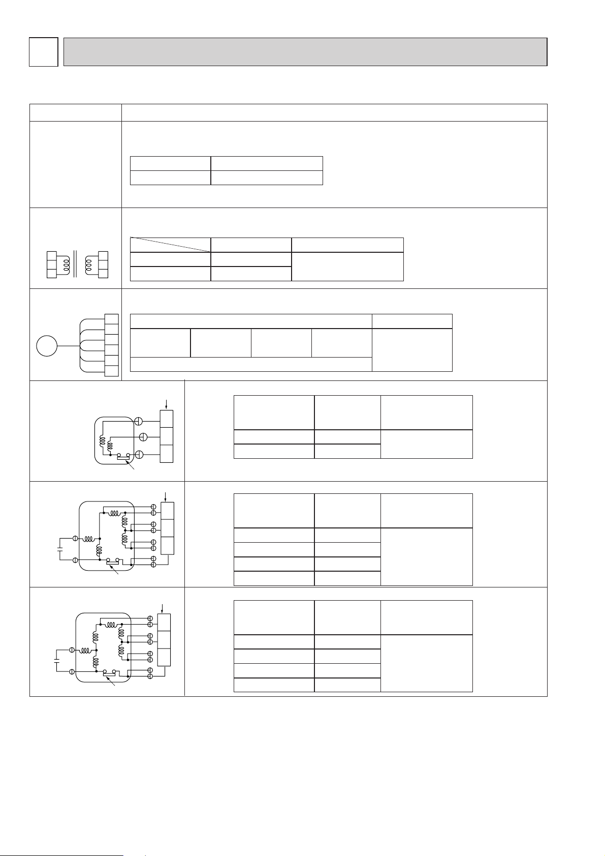
TROUBLE SHOOTING
7-1. How to check the parts
Room temparature
thermistor
(TH21)
Liquid pipe thermistor
(TH22)
Gas pipe thermistor
(TH23)
Trans
Fan motor
Linear expansion
valve
Disconnect the connector, then measure the resistance using a tester.
(Sorrounding temperature 10°C~30°C)
Disconnect the connector and measure the resistance using a tester.
Measure the resistance between the terminals using a tester. (at 20˚C)
Disconnect the connector then measure the resistance valve using a tester.
Refer to the next page for detail.
(Refer to the thermistor)
Normal
4.3kΩ~9.6kΩ
Abnormal
Open or short
CNT(1)-(3)
Normal
App.45Ω
CN3T(1)-(3) App.1Ω
Abnormal
Open or short
Motor terminal
or
Relay connector
Normal Abnormal
Red-Black 43.1Ω
Open or short
White-Black 53.6Ω
Normal
(1)-(5)
White-Red
150Ω ±10%
Abnormal
Open or short
(2)-(6)
Yellow-
Blown
(3)-(5)
Orange-Red
(4)-(6)
Blue-Brown
Parts name Check points
PEFY
- P20~80VMM-E
PEFY
- P100VMM-E
PEFY
-
P125•140VMM-E
Motor terminal
or
Relay connector
Normal Abnormal
Orange-Gray 26.7Ω
Open or short
Black-Gray 32.5Ω
Yellow-Gray 37.9Ω
Blue-Gray 42.4Ω
Motor terminal
or
Relay connector
Normal Abnormal
Orange-Gray 11.6Ω
Open or short
Black-Gray 13.6Ω
Blue-Gray 15.4Ω
Yellow-Gray 18.1Ω
Measure the resistance between the terminals using a tester. (at 20˚C)
Measure the resistance between the terminals using a tester. (at 20˚C)
13
CNT T CN3T
Red Blue
1
2
3
White
Blue
White
Yellow
Orange
LEV
Blue
Red
Brown
Red
C
White
Red
C
White
Protector
1
2
3
CN60
1
2
3
4
5
6
Relay connector
Relay connector
Protector
Relay connector
1
Red
White
2
3
Black
Protector
Orange
Black
Yellow
Yellow
Blue
Blue
Gray
Gray
1
3
5
5
1
4
3
3
7
1
Orange
Black
Blue
Blue
Yellow
Yellow
Gray
Gray
5
1
3
3
4
7
1
Page 15

<Thermistor Characteristic graph>
Room temparature thermistor(TH21)
Liquid pipe thermistor(TH22)
Gas pipe temparature thermistor(TH23)
Drain sensor(DS)
Thermistor R
0=15kΩ ± 3%
Fixed number of B=3480kΩ ± 2%
Rt=15exp { 3480( ) }
0˚C 15kΩ
10˚C 9.6kΩ
20˚C 6.3kΩ
25˚C 5.2kΩ
30˚C 4.3kΩ
40˚C 3.0kΩ
Thermistor for
lower temperature
Linear expansion valve
①
Operation summary of the linear expansion valve.
• Linear expansion valve open/close through stepping motor after receiving the pulse signal from the indoor controller board.
• Valve position can be changed in proportion to the number of pulse signal.
<Connection between the indoor controller board and the linear expansion valve>
1
273+t
1
273
14
< Thermistor for lower temperature >
50
40
30
Resistance (kΩ)
20
10
0
-20 -10 0 10 20 30 40 50
Temperature (˚C:)
Linear expansion valve
4
M
6
2
5
White
1
Red
3
Orange
Blue
Brown
Yellow
ø4
ø3
ø2
ø1
Brown
Red
Blue
Orange
Yellow
White
Connector(CN60)
Controller board
DC12V
6
5
4
3
2
1
Drive circuit
ø4
ø3
ø2
ø1
Page 16

Output
(Phase)
Output
ø1
1
ON
ø2 ON
ø3 OFF
ø4 OFF
2
OFF
ON
ON
OFF
3
OFF
OFF
ON
ON
4
ON
OFF
OFF
ON
<Output pulse signal and the valve operation>
➁
Linear expansion valve operation
➂
Trouble shooting
Symptom
Check points
Operation circuit failure of the micro
processor.
Disconnect the connector on the controller board, then connect LED for checking.
Pulse signal will be sent out for 10 seconds as soon as the
main switch is turned on. If there is LED lights on or lights
off, it means the operation circuit is abnormal.
Countermeasures
Exchange the indoor controller board due to drive
circuit failure.
Linear expansion
valve mechanism is
locked.
Valve doesn
´t close
completely (thermistor leaking).
Wrong connection of
the connector or
contact failure.
To check the linear expansion valve, operate the indoor unit in
fan mode and at the same time operate other indoor units in
cooling mode, then check the pipe temperature <liquid pipe
temperature> of the indoor unit by the outdoor multi controller board operation monitor. During fan operation, linear expansion
valve is closed completely and if there are
some leaking, detecting temperature of the
thermistor will go lower. If the detected
temperature is much lower than the temper-
ature indicated in the remote controller, it
means the valve is not closed all the way. It is not necessary
to exchange the linear expansion valve, if the leakage is small
and not making any trouble.
Motor will idle and make ticking noise when motor is operated
while the linear expansion valve is locked. This ticking sound
is the sign of the abnormality.
Check the color of lead wire and missing terminal of the connector.
Exchange the linear
expansion vale.
Exchange the linear
expansion valve.
If large amount of refrigeration is leaked, exchange
the linear expansion valve.
Disconnect the connector
at the controller board,
then check the continuity.
Measure the resistance between the each coil (red-white,
red-orange, brown-yellow, brown-blue) using a tester. It is
normal if the resistance is in the range of
Short or breakage of
the motor coil of the
linear expansion
valve.
Closing a valve : 1 → 2 → 3 → 4 → 1
Opening a valve : 4 → 3 → 2 → 1 → 4
The output pulse shifts in above order.
✻1. When linear expansion valve operation stops, all output phase
become OFF.
2. At phase interruption or when phase does not shift in order,
motor does not rotate smoothly and motor will lock and vibrate.
✻ When the switch is turned on, 2200 pulse closing valve signal will
be send till it goes to A point in order to define the valve position.
When the valve operates correctly, there is no noise or vibration
occurring from the linear expansion valve : however, when the
pulse number moves from E to A or when the valve is locked,
more noise can be heard than normal situation.
✻ Noise can be detected by placing the ear against a screw driver
handle while touching the screw driver to the linear expansion
valve.
15
Close
Valve position (capacity)
A
E
Open
D
C
2000 pulse
Opening a valve
all the way
Extra tightning (80~100pulse)
B
Pulse number
LED1kΩ
Thermistor
(TH21)
Linear
expansion
valve
6
5
4
3
2
1
10%.
150Ω
Page 17

7-2. FUNCTION OF DIP-SWITCH
:When both SW1-7 and SW1-8 are being set to ON, the fan stops at the heating thermostat OFF.
16
Switch Pole
1
2
3
4
SW1
Mode
Selection
5
6
7
8
9
10
SW2
Capacity
code
1~6
setting
Function
Operation by switch
ON OFF
Thermistor<Intake temperature
detection>position
Built-in remote controller
Filter clogging detection Provided Not provided
Filter life 2,500hr 100hr
Air intake Effective Not effective
Remote indication switching Thermostat ON signal indication Fan output indication
Humidifier control Operational while the heat is ON
Air flow st Low Extra low
Heat thermostat OFF Setting air flow Reset to SW1-7
Auto reset function Effective Not effective
Power ON/OFF Effective Not effective
MODELS SW2 MODELS SW2 MODELS SW2
PEFY-
P20VMM-E
PEFY-
P25VMM-E
PEFY-
P32VMM-E
PEFY-
P40VMM-E
ON
OFF
ON
OFF
ON
OFF
ON
OFF
123456
123456
123456
123456
PEFY-
P50VMM-E
PEFY-
P63VMM-E
PEFY-
P71VMM-E
PEFY-
P80VMM-E
ON
OFF
OFF
ON
OFF
ON
OFF
ON
123456
123456
123456
123456
Indoor unit
Operational, depending on the condition
PEFY-
P100VMM-E
PEFY-
P125VMM-E
PEFY-
P140VMM-E
ON
OFF
OFF
ON
OFF
ON
123456
123456
123456
Remarks
Address board
Indoor controller board
Set while the unit is off.
<At delivery>
Set for each capacity.
Heat pump/Cool only Cooling only Heat pump
SW3
Function
Selection
1
Louver Available Not available
2
Vane Available Not available
3
Vane swing function Available Not available
4
Vane horizontal angle Second setting First setting
5
Vane cooling limit angle setting
6
Horizontal angle Down blow
7
Heating 4deg up Not effective Effective
8
Indoor controller board
Set while the unit is off.
9
10
P20~P80
SW4
Unit
1~4
Selection
ON
OFF
1234
<At delivery>
Note :The DipSW setting is effective during unit stopping ( remote controller OFF ) for SW1,2,3 and 4 commonly and the
power source is not required to reset.
P100~P140
ON
OFF
Indoor controller board
Set while the unit is off.
1234
Page 18

17
3
2
1
100Pa
50Pa
30Pa
Option
Standard
SWC
220V
240V
1
2
3
(SWA)
0
5
9
4
8
3
7
2
6
1
SW12
10
0
5
9
4
8
3
7
2
6
1
SW11
1
0
8
F
7
E
6
D
5
C
4
B
3
A
2
9
1
SW14
0
5
9
4
8
3
7
2
6
1
SW12
0
5
9
4
8
3
7
2
6
1
SW11
0
8
F
7
E
6
D
5
C
4
B
3
A
2
9
1
SW14
Address board
Address board
Address board
Address board
Operation by switchSwitch Pole Remarks
*This switch is for only P20~P80 type.
<At delivery>
<At delivery>
1~3
SWA
Option
2
SWC
Option
SW11
1st digit
address
setting
SW12
2nd degit
address
setting
Rotary switch
SW14
Connect
ion No.
setting
Rotary switch
Address setting should be done when network
remote controller (PAR-F25MA) is being used.
This is the switch to be used when the indoor
unit is operated with R2 series outdoor unit as
a set.
Address board
2
SW5
Voltage
Selection
If the unit is used in the 230V or 240V range,
set the voltage to 240V.
If the unit is being used in a 220V area, set
the voltage
to 220V.
Address can be set while the
unit is stopped.
Note:1
Note:1
Note:2
Note:2
Note:2
Note 1:The DipSW setting is effective always after powering ( remote controller ON ) for SWA and SWC.
2:The DipSW setting is effective during unit stopping ( remote controller OFF ) for SW11,12,14 and 5
Factory setting is for use under an external static pressure of 50Pa,
17
no switch operation is needed when using under the standard
condition.
Page 19

8
DISASSEMBLY PROCEDURE
OPERATING PROCEDURE PHOTOS
1.Removing the control box cover
(1) Remo
2.Re-fit
(1) Re-fit in reverse order, be sure not to catch wires when
re-fitting.
3.Re-fit
(1) Re-fit in reverse order.
ve the covers two fixing screws (A) and remove
the
the covers three fixing screws (B) and remove
the
cover.
cover.
8-1. CONTROL BOX
Be careful on removing heavy parts.
fig.1
fig.2
8-2. THERMISTOR (Liquid piping temperature detection)
OPERATING PROCEDURE PHOTOS
1.Removing the pipe fixing cover
(1) Remove
2.Removing the thermistor
(1) Remove the thermistor from the thermistor holder which is
installed on the copper tube.
fig.1
18
(A)
(B)
Drain pan
Page 20

OPERATING PROCEDURE PHOTOS
1.Removing the thermistor and thermistor holder
(1) Pull out the thermistor holder (C) and thermistor (D).
8-3. THERMISTOR (Intake air temperature detection)
Be careful on removing heavy parts.
fig.1
fig.2
View from the opposite side.
8-4. DRAINPAN
OPERATING PROCEDURE
PHOTOS
1.Removing the drainpan
(1) Remove the drainpan (E) fixing screw .
(2) Slide the drainpan in the direction of the arrow1 and remove
in the direction of the arrow2
Note: The bottom plate can remain in position during this
procedure.
fig.1
fig.2
.
2.Re-fit
(1) Re-fit in reverse order.
2.Re-fit
(1) Re-fit in reverse order.
19
(C),(D)
(C),(D)
(E)
1
2
(E)
Page 21

OPERATING PROCEDURE PHOTOS
1.Remove the drainpan with procedure 8-4
2.Removing the bottom plate 2
(1) Remove the fixing screws (seven) of the bottom plate 2 (F)
and remove plate. fig.1.
3.Removing the thermistor
(1) Remove the thermistor (G) from the thermistor holder (H)
which is installed on the copper tube.
8-5. THERMISTOR (GAS piping temperature detection)
Be careful on removing heavy parts.
fig.1
fig.2
8-6. FAN and FAN MOTOR
OPERATING PROCEDURE PHOTOS
1.Removing the bottom plate 1 (I)
(1) Remove the fixing screws (eight) of the bottom plate 1 (I)
and remove plate.
2.Sliding the fan section
(1) Remove the fan motor cable connector in control box.
(2) Remove the fixing screws (four) of the fan base plate.
(3) Slide the fan section in direction of the arrow1.
fig.1
fig.2
Note: The bottom plate and drain pan can remain in position
during this procedure if accessing through the pipe
cover hole.
Note: The drain pan can remain in position during this
procedure.
4.Re-assemble
(1) Re-assemble in reverse order.
20
(F)
(G),(H)
1
(I)
Fan motor cable
Page 22

OPERATING PROCEDURE PHOTOS
3.Removing the fan casing and sirocco fan
(1) Remove the fan casing fixing screws (four for each fan).
(2) Remove the fan motor shaft fixing screw (one for each fan)
and remove the fan casing and sirocco fan.
4.Removing the fan motor
(1) Remove the
Be careful on removing heavy parts.
fig.3
8-7. HEAT EXCHANGER
OPERATING PROCEDURE PHOTOS
1.Remove the drainpan with procedure 8-4
2.Remove the bottom plate 2 with procedure 8-5
3.Removing Heat exchanger
(1) Remove the fixing screws (four) of the heat exchanger (M)
and remove the heat exchanger.
fig.1
fig.2
Remove the motor clamps (L) two clamps secure the motor
capacitor cable (K).
(2)
on each side (over the rubber bushing).
5.Re-assemble
(1) Re-assemble in reverse order.
Note: Piping, pipe cover and thermistor wires to be removed
first.
4.Re-assemble
(1) Re-assemble in reverse order.
21
(J)
(K)
(L)
Fan motor shaft
fixing screw
(M)
Page 23

Page 24

Issued in April 2004 MEE03K223
Printed in Japan
New publication effective April 2004.
Specifications subject to change without notice.
HEAD OFFICE: MITSUBISHI DENKI BLDG., 2-2-3, MARUNOUCHI, CHIYODA-KU, TOKYO 100-8310, JAPAN
 Loading...