

Page 1
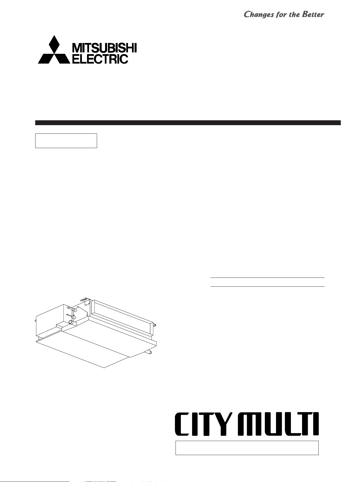
TECHNICAL & SERVICE MANUAL
Air-Conditioners For Building Application
<Indoor unit>
2005
Models
Ceiling Concealed
Series PEFY
PEFY-P06NMLU-E
PEFY-P08NMLU-E
PEFY-P12NMLU-E
INDOOR UNIT
CONTENTS
SAFETY PRECAUTIONS ·························1
1. FEATURES ···········································3
2. PART NAMES AND FUNCTIONS········4
3. SPECIFICATION ···································6
4. OUTLINES AND DIMENSIONS············8
5. WIRING DIAGRAM ·······························9
6.
REFRIGERANT SYSTEM DIAGRAM
····10
7. TROUBLE SHOOTING ·······················11
8. DISASSEMBLY PROCEDURE···········
14
For use with the R410A & R22
Page 2
SAFETY PRECAUTIONS
and install the unit at the specified place.
- Improper installation may cause the unit to topple and result in
injury.
• Always use an air cleaner, humidifier, electric heater, and other
accessories specified by Mitsubishi Electric.
- Ask an authorized technician to install the accessories. Improper
installation by the user may result in water leakage, electric shock,
or fire.
• Never repair the unit. If the air conditioner must be repaired,
consult the dealer.
- If the unit is repaired improperly, water leakage, electric shock, or
fire may result.
• Do not touch the heat exchanger fins.
- Improper handling may result in injury.
• If refrigerant gas leaks during installation work, ventilate the
room.
- If the refrigerant gas comes into contact with a flame, poisonous
gases will be released.
• Install the air conditioner according to this Installation Manual.
- If the unit is installed improperly, water leakage, electric shock, or
fire may result.
• Have all electric work done by a licensed electrician according
to “Electric Facility Engineering Standard” and “Interior Wire
Regulations”and the instructions given in this manual and always use a special circuit.
- If the power source capacity is inadequate or electric work is per-
formed improperly, electric shock and fire may result.
• Securely install the cover of control box and the panel.
- If the cover and panel are not installed properly,dust or water may
enter the outdoor unit and fire or electric shock may result.
• When installing and moving the air conditioner to another site,
do not charge the it with a refrigerant different from the refrigerant specified on the unit.
- If a different refrigerant or air is mixed with the original refrigerant,
the refrigerant cycle may malfunction and the unit may be damaged.
• If the air conditioner is installed in a small room, measures
must be taken to prevent the refrigerant concentration from
exceeding the safety limit even if the refrigerant should leak.
- Consult the dealer regarding the appropriate measures to pre-
vent the safety limit from being exceeded. Should the refrigerant
leak and cause the safety limit to be exceeded, hazards due to
lack of oxygen in the room could result.
• When moving and reinstalling the air conditioner, consult the
dealer or an authorized technician.
- If the air conditioner is installed improperly, water leakage, elec-
tric shock, or fire may result.
• After completing installation work, make sure that refrigerant
gas is not leaking.
- If the refrigerant gas leaks and is exposed to a fan heater, stove,
oven, or other heat source, it may generate noxious gases.
• Do not reconstruct or change the settings of the protection
devices.
- If the pressure switch, thermal switch, or other protection device
is shorted and operated forcibly, or parts other than those specified
by Mitsubishi Electric are used, fire or explosion may result.
1. Before installation and electric work
s Before installing the unit, make sure you read all the
“Safety precautions”.
s The “Safety precautions” provide very important
points regarding safety. Make sure you follow them.
s This equipment may cause the adverse effect on the
same supply system.
s Please report to or take consent by the supply au-
thority before connection to the system.
Symbols used in the text
Warning:
Describes precautions that should be observed to prevent danger
of injury or death to the user.
Caution:
Describes precautions that should be observed to prevent damage
to the unit.
Symbols used in the illustrations
: Indicates an action that must be avoided.
: Indicates that impor tant instructions must be followed.
: Indicates a part which must be grounded.
: Indicates that caution should be taken with rotating parts. (This
symbol is displayed on the main unit label.) <Color: Yellow>
: Beware of electric shock (This symbol is displayed on the main
unit label.) <Color: Yellow>
Warning:
Carefully read the labels affixed to the main unit.
Warning:
• Ask the dealer or an authorized technician to install the air conditioner.
- Improper installation by the user may result in water leakage, elec-
tric shock, or fire.
• Install the air unit at a place that can withstand its weight.
- Inadequate strength may cause the unit to fall down, resulting in
injuries.
• Use the specified cables for wiring. Make the connections securely so that the outside force of the cable is not applied to the
terminals.
- Inadequate connection and fastening may generate heat and cause
a fire.
• Prepare for typhoons and other strong winds and earthquakes
• Keep the electric parts away from water (washing water etc.).
- It might result in electric shock, catching fire or smoke.
• To dispose of this product, consult your dealer.
• Do not use a leak detection additive.
1
Page 3
2
2. Precautions for devices that use
Caution:
• Do not use the existing refrigerant piping.
- The old refrigerant and refrigerator oil in the existing piping contains a large amount of chlorine which may cause the refrigerator
oil of the new unit to deteriorate.
• Use refrigerant piping made of C1220 (Cu-DHP) phosphorus
deoxidized copper as specified in the *JIS H3300 “Copper and
copper alloy seamless pipes and tubes”. In addition, be sure
that the inner and outer surfaces of the pipes are clean and
free of hazardous sulphur, oxides, dust/dirt, shaving particles,
oils, moisture, or any other contaminant.
- Contaminants on the inside of the refrigerant piping may cause
the refrigerant residual oil to deteriorate.
*JIS: Japanese Industrial Standard
• Store the piping to be used during installation indoors and keep
both ends of the piping sealed until just before brazing. (Store
elbows and other joints in a plastic bag.)
- If dust, dirt, or water enters the refrigerant cycle, deterioration of
the oil and compressor trouble may result.
• Use ester oil, ether oil or alkylbenzene (small amount) as the
refrigerator oil to coat flares and flange connections.
- The refrigerator oil will degrade if it is mixed with a large amount of
mineral oil.
• Use liquid refrigerant to fill the system.
- If gas refrigerant is used to seal the system, the composition of
the refrigerant in the cylinder will change and performance may
drop.
• Do not use a refrig
- If another refrigerant (R22, etc.) is used, the chlorine in the refrig-
erant may cause the refrigerator oil to deteriorate.
• Use a vacuum pump with a reverse flow check valve.
- The vacuum pump oil may flow back into the refrigerant cycle and
cause the refrigerator oil to deteriorate.
• Do not use the following tools that are used with conventional
refrigerants.
(Gauge manifold, charge hose, gas leak detector, reverse flow
check valve, refrigerant charge base, vacuum gauge, refrigerant recovery equipment)
- If the conventional refrigerant and refrigerator oil are mixed in the
• Do not use a charging cylinder.
- Using a charging cylinder may cause the refrigerant to deteriorate.
• Be especially careful when managing the tools.
- If dust, dirt, or water gets in the refrigerant cycle, the refrigerant
may deteriorate.
R410A refrigerant
erant other than R410A.
R410A , the refrigerant may deteriorated.
- If deteriorate.water is mixed in the R410A , the refrigerator oil may
- Since R410A does not contain any chlorine, gas leak detectors
for conventional refrigerants will not react to it.
Warning:
Note the following when building a heater in the air
conditioning system.
- Leave enough space between units for proper ventilation so that
the indoor unit temperature does not exceed 40˚C when
windless.
- Keep the heater clean, and take appropriate measures so that
the indoor unit does not suck in the dust particles that
accumulate on the heater.
- Use the optional heater cable (PAC-YU24HT) to perform an
interlocked operation with indoor units.
- Do not build a heater inside the indoor unit.
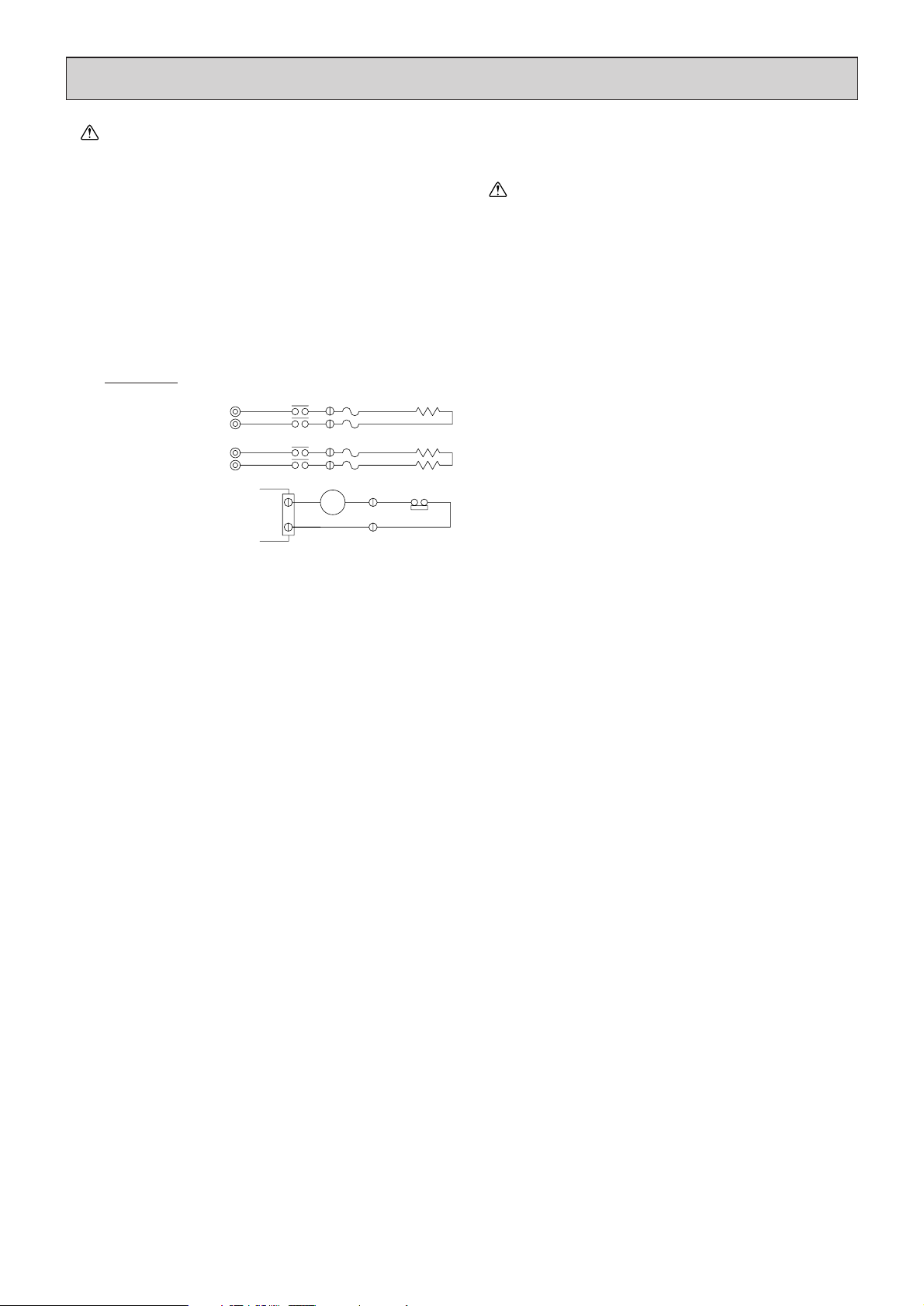
•
Recommended circuit
FS1
FS2
FS1
FS2
R
S
R
S
CN24
H2
88H
H1
88H
26H
88H
Wiring diagram
1-phase power
supply
208V, 230V/60Hz
Control board
FS1, 2 ----- Thermal fuse
H1, H2 ----- Heater
26H --------- Overheat protection
thermostat
88H --------- Electromagnetic contactor
Page 4
3
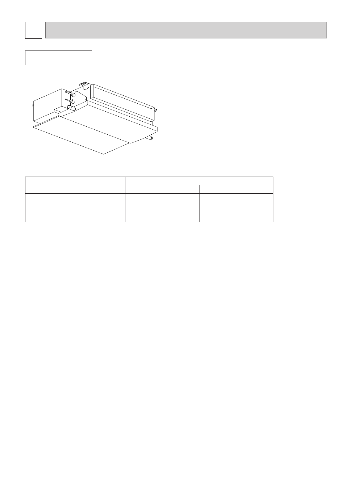
PEFY-P06NMLU-E
PEFY-P08NMLU-E
PEFY-P12NMLU-E
1.8 / 2.0
2.3 / 2.6
3.5 / 4.0
FEATURES
1
Indoor unit
Ceiling Concealed
Series PEFY
Models
Cooling capacity/Heating capacity
kW
6000 / 6700
8000 / 9000
12000 / 13500
BTU / h
Page 5
4
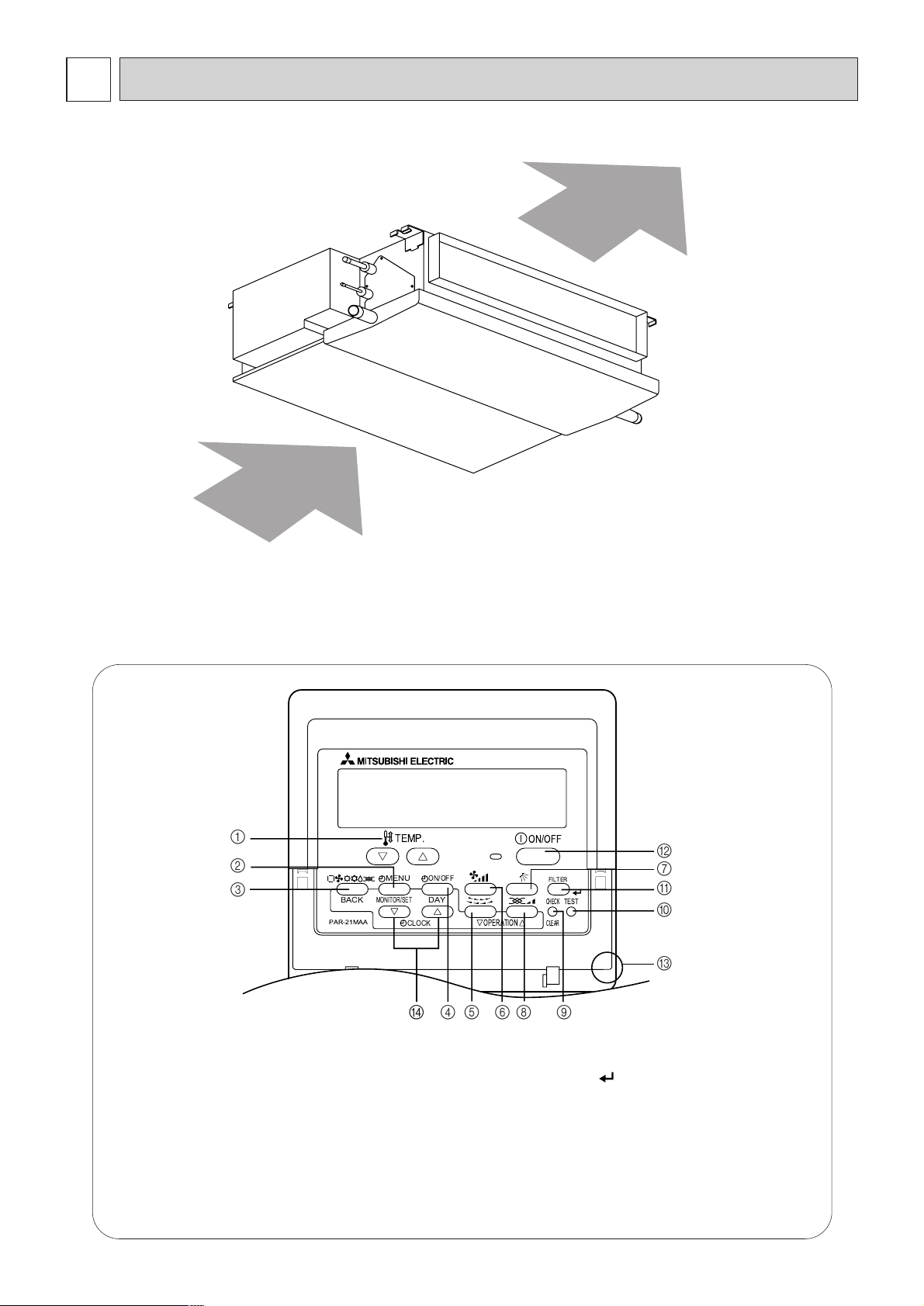
PART NAMES AND FUNCTIONS
2
● Indoor (Main) Unit
● Remote controller
[Operation buttons]
[PAR-21MAA]
● Once the controls are set, the same operation mode can
be repeated by simply pressing the ON/OFF button.
Air inlet
Air outlet
1 [Set Temperature] Button
2 [Timer Menu] Button
[Monitor/Set] Button
3 [Mode] Button
[Return] Button
4 [Timer On/Off] Button
[Set Day] Button
7 [Airflow Up/Down] Button
[Ventilation] Button
[Operation] Button
5 [Louver] Button
[Operation] Button
6 [Fan Speed] Button
[Check/Clear] Button
0 [Test run] Button
A
8
9
[Filter] Button
[ ] Button
B
C
D
[ON/OFF] Button
Position of built-in room temperature
[Set Time] Button
Ne• ver expose the remote controller to direct sunlight. Doing so can result in the erroneous measurement of room temperature.
• Never place any obstacle around the lower right-hand section of the remote controller. Doing so can
result in the erroneous measurement of room temperature.
PAR-21MAA
ON/OFF
FILTER
CHECK
OPERATION
CLEAR
TEST
TEMP.
MENU
BACK DAY
MONITOR/SET
CLOCK
ON/OFF
1
2
3
4D 568 9
0
C
A
B
7
Page 6
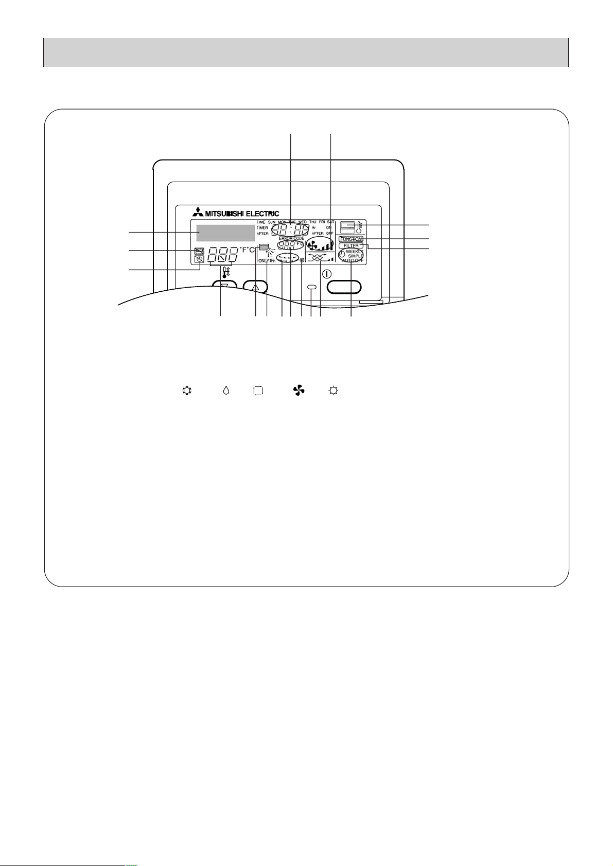
[Display]
C
C
ON/OFF
CENTRALLY CONTROLLED
ERROR CODE
CLOCK
ON OFF
CHECK
CHECK MODE
FILTER
TEST RUN
FUNCTION
1Hr.
NOT AVAILABLE
STAND BY
DEFROST
TEMP.
A
B
C
E
P
M
F
K
D
OLGNIHJQ
A
Current time/Timer
B
Centralized control
C
Timer OFF
D
Timer indicator
E
Operation mode: COOL, DRY, AUTO, FAN, HEAT
F
“Locked” indicator
G
H
Set temperature
I
Power ON
J
Louver
K
L
Ventilation
M
N
O
P
Filter sign
Set effective for 1 hr.
Sensor position
Room temperature
Airflow
Fan speed
5
Page 7
6
3
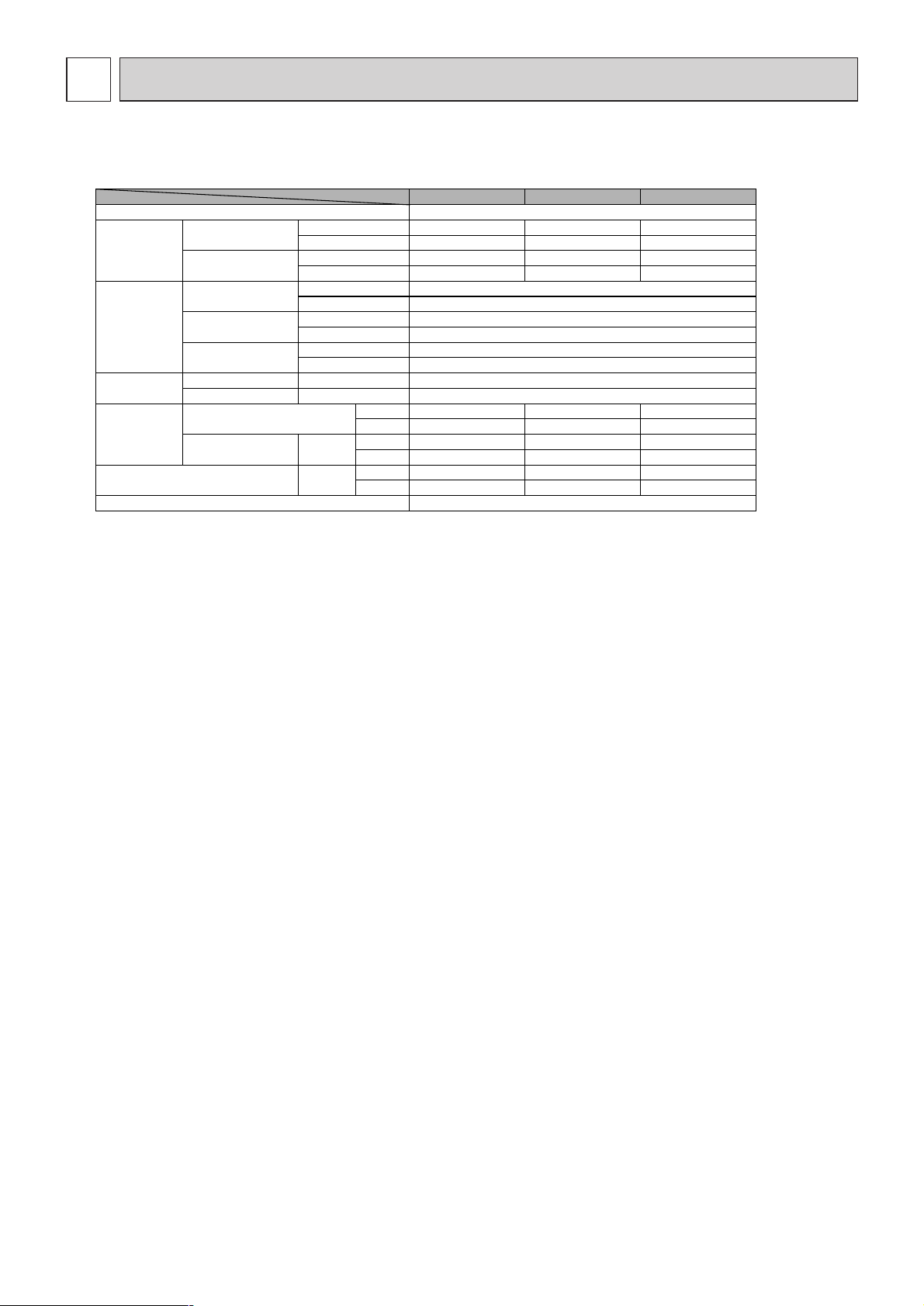
SPECIFICATION
3-1. Specification
Notes: *1 Cooling/Heating capacity indicates the maximum value at operation under the following condition.
Cooling: Indoor: 26.7 °C [80 °F] DB/19.4 °C [67 °F] WB Outdoor: 35 °C [95 °F] DB
Heating: Indoor: 21.1 °C [70 °F] DB Outdoor: 8.3 °C [47 °F] DB/6.1 °C [43 °F] WB
*2 The operating noise is the data that was obtained in an anechoic room.
Item Model
PEFY
PEFY-P-NMLU-E
-P06NMLU-E PEFY-P08NMLU-E PEFY-P12NMLU-E
Power sourse 208/230V, 60Hz
Capacity
*1
Cooling
kW 1.8 2.3 3.5
BTU/h 6000 8000 12000
Heating
kW 2.0 2.6 4.0
BTU/h 6700 9000 13500
Dimension
Height
mm 225
in 8-7/8
Width
mm 790
in 31-1/8
Depth
mm 550
in 21-21/32
Net weight
kg 18
lb 40
FAN
Airflow rate
(Low-Middle-High)
m
3
/min 4.8-5.8-7.9 4.8-5.8-7.9 4.8-5.8-9.5
cfm 169-205-279 169-205-279 169-205-335
External static
pressure
Pa
208V 5 5 5
230V 5 5 5
Noise level
(Low-Middle-High) *2
dB(A)
208V 25-29-36 25-29-36 25-29-40
230V 25-29-36 25-29-36 25-29-40
Filter Standard filter
Page 8
7
LEV
C1
MF1,2
PEFY-P06NMLU-E
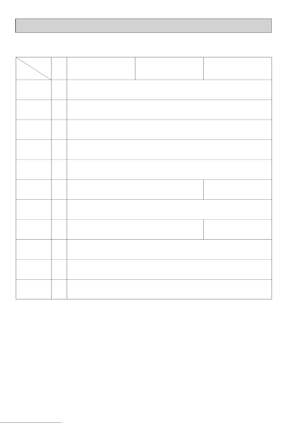
3-2. Electrical parts specifications
Model
Parts
name
Tranrsformer T (Primary) 50/60Hz 220-240V (Secondry) (23.5V 0.9A)
TH21
Resistance 0˚C[32˚F]/15kΩ,10˚C[50˚F]/9.6kΩ,20˚C[68˚F]/6.3kΩ,25˚C[77˚F]/5.4kΩ,
30˚C[86˚F]/4.3kΩ,40˚C[104˚F]/3.0kΩ
TH22
Resistance 0˚C[32˚F]/15kΩ,10˚C[50˚F]/9.6kΩ,20˚C[68˚F]/6.3kΩ,25˚C[77˚F]/5.4kΩ,
30˚C[86˚F]/4.3kΩ,40˚C[104˚F]/3.0kΩ
Gas pipe
thermistor
FUSE 250V 6.3A
TB2 (L1,L2,G) 330V 30A
TB5
TB15
(1,2),(M1,M2,S) 300V 10A
Fuse
(Indoor con-
troller board)
Power supply
terminal bed
Transmission
terminal bed
PEFY-P08NMLU-E PEFY-P12NMLU-E
OFF 135˚C
±5˚C[275˚F±41˚F]
ON 95˚C
±15˚C[203˚F±59˚F]
Room
temperature
thermistor
Fan motor
(with Inner-
thermostat)
4-pole Output 23W
CRC4417BB
4-pole Output 32W
CRC4418BB
Symbol
DC12V Stepping motor drive port dimension ø3.2
TH23
Resistance 0˚C[32˚F]/15kΩ,10˚C[50˚F]/9.6kΩ,20˚C[68˚F]/6.3kΩ,25˚C[77˚F]/5.4kΩ,
30˚C[86˚F]/4.3kΩ,40˚C[104˚F]/3.0kΩ
Innerthermostat
(Fan motor)
Liquid pipe
thermistor
Fan motor
capacitor
Linear
expansion valve
1.7µF✕440V
2.5µF✕440V
(0~1800pulse <at R410A outdoor unit>, 0~2000pulse <at the other outdoor unit>)
Page 9
8
4
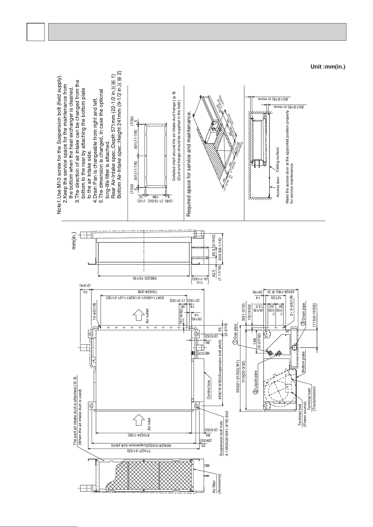
OUTLINES AND DIMENSIONS
PEFY-P06·08·12NMLU-E
Drain pipe
Gas pipe
Liquid pipe
Ceiling surface
Access door
Make the access door at the appointed position properly
for service maintenance.
Required space for service and maintenance.
Suspension bolt hole
4-14X30(9/16X1-3/16) Slot
Air filter
(Accessory)
Note1.Use M10 screw for the Suspension bolt (field supply).
2.Keep the service space for the maintenance from
the bottom when the heat exchanger is cleaned.
3.The direction of air intake can be changed from the
bottom to the rear by attaching the bottom plate
to the air intake side.
4.Drain Pan is changeable from right and left.
5.The dimension is changed, in case the optional
long-life filter is attached.
Rear Air-Intake spec.:Depth 571mm (22-1/2 in.)( 1)
Bottom Air-Intake spec.:Height 241mm (9-1/2 in.)( 2)
Control box
Terminal bed
(Transmission)
Terminal bed
(Power source)
Bottom plate
The part air intake duct is attached.( 3)
(When the air intake duct is used)
Detailed chart around the air intake duct frange.
(3)
(Duct and frange should be supplied in the field.)
mm(in.)
12-¿3(1/8)
Air outlet
Air inlet
23-
¿3(1/8)
450
(17-23/32)
50~150
(1-31/32~5-29/32)
300
(11-13/16)
(17-23/32)
450
25
(1)
500
(19-11/16)
50~150
110
(4-11/32)
)(
80
(3-5/32)
55
(2-3/16)
50X11=550(1-31/32X11=21-21/32)
16
(21/32)
582(22-15/16)
14
(9/16)
459(18-3/32)(Suspension bolt pitch)
15(19/32)
(113(4-15/32))
23
(29/32)
664(26-5/32)(Suspension bolt pitch)
720(28-3/8)
710(27-31/32)
225(8-7/8)( 2)
610(24-1/32)
50
(1-31/32)
80
(3-5/32)
30(1-3/16)
15(19/32)
148
(5-27/32)
13.5
204.5(8-1/16)
50
50
(9/16)
(1-
31/32)
(1-
31/32)
510(20-3/32)
14
(9/16)
127(5)
65.5
(2-19/32)
42.5
(1-11/16)
129
55
(7/32)(7/32)
301(11-7/8) 301(11-7/8)
189
(1/2)(3/8) (7-15/32)
550(21-21/32)( 1)
20(13/16) or more
20(13/16) or more
70
(2-3/4)
2
1
3
(1-31/32
~5-29/32)
Unit :mm(in.)
Page 10

9
5
WIRING DIAGRAM
PEFY-P06·08·12NMLU-E
NOTE;1.The wirings to TB2,TB5,TB15 shown in chained line are field work.
2.Mark indicates terminal bed, connector, board
insertion connector or fastening connector of control board.
Switch(for mode selection)
Switch(for model selection)
Switch(for capacity code)
Switch(for model selection)
Switch (connection No.set)
Switch (2nd digit address set)
Switch(for voltage selection)
Switch(for mode selection)
Thermistor (piping temp.detection/gas)
Thermistor (piping temp.detection/liquid)
Varistor
SW3(I.B.)
SW4(I.B.)
NAME
Connector
Connector CN25
ConnectorCN27
CN24
SW2(I.B.)
SW1(A.B.)
SW14(A.B.)
SW12(A.B.)
SW11(A.B.)
SW7(A.B.)
SW5(A.B.)
Switch (1st digit address set)
Connector (HA terminal-A)
Connector
Connector
Connector (Centrally control)
Power supply (Remote controller)
Power supply (I.B.)
CN51
CN41
CN23
CN22
LED2
LED1
SYMBOL SYMBOL
NAME
TH22
TH23
Thermistor (inlet temp.detection)
TH21
ZNR,ZNR1
CN32 Connector (Centrally control)
CN52 Connector (Remote indication)
Aux.relay
NAME
SYMBOL EXPLANATION
Power source terminal bed
Transmission terminal bed TB5
Transmission terminal bedTB15
TB2
Transformer
Address board
Indoor controller board
Electronic linear expan. valve
Capacitor (for MF)
Fan motor
LEV
T
A.B.
I.B.
C
MF
SYMBOL
X04X01,
~
X06
F1 Fuse AC250V 6.3A T
S.B. Surge absorber board
S.B. TB2 TB5,TB15
C
I.B.
A.B.
CONTROL BOX
PARTS LOCATION
The motor connector is connected
with 230V power at factory shipment.
If 208V power is used insert
the attachment.
TO OUTDOOR UNIT
BC CONTROLLER
REMOTE
CONTROLLER
BREAKER
(15A)
FUSE
(15A)
PULL
BOX
TO NEXT INDOOR UNIT
TO DUCT
POWER SUPPLY
~
208/230V 60Hz
TO MA REMOTE
CONTROLLER
*
insert
Color / Power source
White / 230V
Blue / 208V
1
2
3
4
5
6
7
8
0
8
7
6
5
4
3
2
1
0
9
8
7
6
5
4
3
2
1
0
9
9
A
B
C
D
E
F
TB5 (TRANSMISSION
TERMINAL BED)
TB15 (TRANSMISSION
TERMINAL BED)
(Blue)
CN42
CN81
CN32
CN82
CN62
CN20 CN21 CN29 CN31 CN60 CN3T
CN2M
CN3A
CNT CND
CN1
CNP
ZNR
ZNR1
DSA1
X01
X06 X05 X04
LED1 LED2
CN52 CN51 CN41 CN23 CN24 CN25 CN27 CN22
FAN2
FAN3
TB2
L1
L2
G
432
1
531
432
1
12121212 654321
123456
331
T
13
3
35731
1
2
1
3
1
2
1
M2
M1
11
876
5
567
8
123
4
A.B.
(White)
MF
C
LEV
TH21 TH22 TH23
SW14
(Connection No.)
SW11
(1st digit)
SW12
(2nd digit)
()
AC250V
6.3A T
F1
(Yellow)
(Red) (Green)(Green) (Yellow)(White)
(Yellow)
S.B.
I.B.
(Blue)
(Blue)
(Blue)
(White)
(Red)
(White)
(Red)
(Red) (Black)
(White)
(White)
(White)
(White)(White)(White) (Green)
(Red)
(Red)
SW4 SW3 SW2
(White)
(White)
SW1 SW5 SW7
S(SHIELD)
INSIDE SECTION OF CONTROL BOX
276 1345
276 1345
276 1345
276 1345
Page 11

10
REFRIGERANT SYSTEM DIAGRAM
6
Gas pipe
PEFY-P06·08·12NMLU-E
mm <in.>
ø
12.7<1/2>
Liquid pipe
ø
6.35<1/4>
Capacity
Item
Gas pipe thermistor TH23
Liquid pipe thermistor TH22
Heat exchanger
Linear expansion valve
Strainer (#100mesh)
Room temperature thermistor TH21
Gas pipe
Brazed joints
Strainer (#100mesh)
Page 12

11
7
TROUBLE SHOOTING
7-1. How to check the parts
Room temperature
thermistor
(TH21)
Liquid pipe thermistor
(TH22)
Gas pipe thermistor
(TH23)
Trans
Fan motor
Linear expansion
valve
Disconnect the connector, then measure the resistance using a tester.
(Sorrounding temperature 10°C~30°C[50°F~86°F])
Disconnect the connector and measure the resistance using a tester.
Measure the resistance between the terminals using a tester. (at 20˚C[68°F])
Disconnect the connector then measure the resistance valve using a tester.
(Refer to the thermistor characteristic graph)
Normal
4.3kΩ~9.6kΩ
Abnormal
Open or short
CNT(1)-(3)
Normal
App.15Ω
CN3T(1)-(3) App.4Ω
Abnormal
Open or short
Motor terminal
or
Relay connector
Normal
P06· 08
P12
Abnormal
White-Black
261
Ω
Open or short
White-Brown
White-Yellow
White-Blue
294
Ω
389
Ω
475
Ω
232
Ω
259
Ω
450
Ω
536
Ω
Normal
(1)-(5)
White-Red
150Ω±10%
Abnormal
Open or short
(2)-(6)
Yellow-
Brown
(3)-(5)
Orange-Red
(4)-(6)
Blue-Brown
Parts name Check points
PEFY-P06·08·12
<Thermistor characteristic graph>
Room temperature thermistor(TH21)
Liquid pipe thermistor(TH22)
Gas pipe temperature thermistor(TH23)
Drain sensor(DS)
Thermistor R
0=15kΩ±3%
Fixed number of B=3480k
Ω ± 2%
Rt=15exp { 3480( ) }
0˚C15kΩ
10˚C 9.6kΩ
20˚C 6.3kΩ
25˚C 5.2kΩ
30˚C 4.3kΩ
40˚C
32˚F
50˚F
68˚F
77˚F
86˚F
104˚F 3.0kΩ
0
10
20
30
40
50
-20 -10
0 1020304050 (˚C)
-4 14 32 50 68 86
104 122
[˚F]
Temperature
Resistance (kΩ)
1
273+t
1
273
CN3T
3
CNT
1
3T
Protector
LEV
CN60
White
Yellow
Orange
Blue
Red
Brown
Relay connector
White
1
Orange
2
Red
3
Black
4
Brown
7
Yellow
5
Blue
6
1
2
3
4
5
6
Page 13

12
CN62
SW1
SW7
ON
ON
ON
W254665G06
JP2
SW14
FP-AD-R
CN82
681 1
240V 220V
1
1
01
12
ASSY
2
34567891021
345678 9
G23
1
1
O
F
F
2
3
3
ABCDE F
10
JP1
SW5SWCSWA
1
3
2
SW12 SW11
0
1
2
3
4
5
6
7
8
9
A
B
C
D
E
F
0
1
2
3
4
5
6
7
8
9
0
1
2
3
4
5
6
7
8
9
7-2. Setting of address switch
Make sure that power source is turning off.
ON
OFF
123456789
10
SW1
Indoor unit control board
< At delivery (All models)>
< At delivery (All models)>
Refer to the next page for SW2,SW3 setting.
SW2 SW3
1)In case using M-NET remote controller, address is set by rotary switches.(SW11,SW12)
* It is not necessary setting address in case of using unit remote controller.
2) Indoor unit address setting rule is different by each field work.
Refer to install manual of outdoor unit , operate the address setting.
3)Setting the address is combination of SW11(1st digit address setting) and SW12(2nd digit address setting).
Address " 3 " setting is composed SW11 " 3 " and SW12 " 0 " .
Address " 25 " setting is composed SW11 " 5 " and SW12 " 2 " .
Indoor unit do not run without address setting in field.
ON
OFF
12 543
SW4
SW4
Page 14

13
7-3. Setting of Dip-switch (at delivery)
Models Dip-SW
7-4. Function
7-4. Function the unit of the indoor
LED service board
12345678910 12345678910 123123456
SW1 SW2
ON
OFF
ON
OFF
ON
OFF
ON
OFF
SW3 SW4
4
ON
OFF
220V
240V
SW5
123
SW4
4
123
SW4
4
5
5
5
12345678910 12345678910123456
ON
OFF
220V
240V
SW5
SW1 SW2
ON
OFF
ON
OFF
ON
OFF
ON
OFF
SW3
12345678910 12345678910123456
ON
OFF
220V
240V
SW5
SW1 SW2
ON
OFF
ON
OFF
ON
OFF
ON
OFF
2
3
1
123
SW7
123
SW7
ON
OFF
123
SW7
SWA
SWA
SWA
ON
OFF
Option
Standard
SWC
Option
Standard
SWC
Option
Standard
SWC
ON
OFF
SW3
2
3
1
2
3
1
PEFYP06NMLU-E
PEFYP08NMLU-E
PEFYP12NMLU-E
Symbol LED operation under normal state
LED1 At applying main power source
LED2
At receiving MA transmission power source
Lighting
Lighting
Page 15

14
8
DISASSEMBLY PROCEDURE
OPERATING PROCEDURE PHOTOS
1.Removing the control box cover
(1) Remove the fixing screws (two) of the control box (A), and
remove the cover. (Fig. 1)
*At this stage, the following servicing is possible.
1 Operation and check of the switches (listed below) which
are on the control board.
• Dip switch SW2 Capacity code setting
• Dip switch SW3 Function change
• Dip switch SW4 Model code setting
2 Operation and check of the switches (listed below) which
are on the adress board.
• Rotary switches SW11, 12 Address setting
• Rotary switch SW14 Branch port setting
• Dip switch SW1 Function change (main)
3 Connection check of the lead wires (listed below) which
are connected to the controller board.
• Power supply lead wire.
• Network remote contoller transmission lead wire.
• Fan motor lead wire.
• LEV lead wire
• Intake air sensor lead wire
• Liquid piping sensor lead wire
• Gas piping sensor lead wire
• Power supply transformer lead wire
• Address board lead wire
4 Control board exchange
5 Address board exchange
6 Condenser exchange
7 Power supply transformer exchange
8 Arrest exchange
9 Intake air sensor exchange
10 Power supply terminal bed exchange
11 Transmission terminal bed exchange
8-1. CONTROL BOX
Be careful on removing heavy parts.
fig.1
fig.2
·················
·················
·················
······
···············
·······················
(A)
Page 16

15
OPERATING PROCEDURE PHOTOS
8-2. FAN and FAN MOTOR
Be careful on removing heavy parts.
fig.3
fig.5
1.Removing the fan casing and sirocco fan.
(1) Remove the bottom plate 1. (fixing screws : six) (Fig. 3)
(2) Remove the fixing screws (three) of the fan casing, and turn
it in direction of arrow. (Fig. 4)
(3) Remove the fixing screws (two) of the fan casing, and loosen
the set screw of the sirocco fan, and remove the fan casing
and sirocco fan. (Fig. 5)
2.Removing the fan motor.
(1) Remove the control box. (fixing screws : three) (Fig. 7)
(2) Move the control box to place that is not block operation.
(Fig. 8)
(3) Remove the fan motor cable connector in the control box,
and remove the screws of the motor support. (Fig. 9)
fig.7
fig.9
fig.4
fig.6
fig.8
Fan casing
Bottom plate1
Set screw
Fan motor
cable connector
Page 17

16
fig.10
fig.11
8-3. DRAINPAN
OPERATING PROCEDURE PHOTOS
1.Removing the drainpan.
(1) Remove the fixing screw (one) of the drainpan.(Fig. 10).
(2) Slide the drainpan in the order of arrow 1,2,3, and remove
the drainpan. (Fig. 11)
Be careful on removing heavy parts.
1
2
3
Page 18

8-4.
LEV,THERMISTOR (Liquid/Gas piping temperature detection)
OPERATING PROCEDURE PHOTOS
1.Removing the LEV.
(1) Remove the drainpan with procedure 8-3.
(2) Remove the bottom plate 2 (fixing screws : six), and remove
the plate.(Fig. 12)
(3) Remove the LEV driving motor with a double spanner.
(Fig.13)
2.Removing the thermistors.
(1) Remove the thermistors from the thermistor holders which
are installed on the piping.(Fig. 14)
(liquid piping : fine piping , gas piping : thick piping)
fig.12
fig.13
fig.14
Be careful on removing heavy parts.
17
LEV
Thermistor
Page 19

8-5. HEAT EXCHANGER
OPERATING PROCEDURE PHOTOS
1.Removing the heat exchanger.
(1) Remove the drainpan with procedure 8-3.
(2) Remove the bottom plate2 with procedure 8-4.
(3) Remove the heat exchanger cover.(fixing screws : four)
(Fig. 15)
(4) Remove the heat exchanger.(fixing screws : three)
(Fig. 16),(Fig. 17)
fig.15
fig16
fig.17
Be careful on removing heavy parts.
18
Heat exchanger
cover
Page 20

19
8-6. CONTROL BOX INSIDE LAYOUT
8-7. SENSOR POSITION
Address board
SWA SWC SW5
SW14 SW12 SW1
SW1
CN82 CN62
Trans
FAN3
X06 X05
X04
L1 L2 G
DSA board
CNDCNTCNP
Indoor unit
contoller board
12
Condenser
(for motor)
Transmission terminal bed
Power sourse
terminal bed
Gas sensor
Liquid sensor
Page 21

Page 22

HEAD OFFICE: MITSUBISHI DENKI BLDG., 2-2-3, MARUNOUCHI, CHIYODA-KU, TOKYO 100-8310, JAPAN
Issued in Aug. 2005 HWE05140
Printed in Japan
New publication, effective Aug. 2005
Specifications subject to change without notice
Page 23

SERVICE PARTS LIST FOR
MITSUBISHI ELECTRIC
PACKAGED AIR-CONDITIONERS
Series PEFY-P•NMLU-E
For use with the R410A
INDEX
P E F Y - P 0 6 N M L U - E
P E F Y - P 0 8 N M L U - E
P E F Y - P 1 2 N M L U - E
REVISED
June 2009
BWE0511A
Please change the old catalog (issued July 2005, BWE05110) to this new catalog.
Content of revision : Some of parts are changed.
Page 24

PEFY-P06,P08,P12NMLU-E
EXTERNAL PARTS
109
104
101.102.103
105
110
111
108
107
106
G : RoHS Apply Only
No. Part No.
101 R61 Y26 483 W Heat exchanger assy 1 1 1 W265695G25 A
102 R63 902 936 G Thermistor(gas) NTH3A23-4<TH23> 1 1 1 P425491X01 A
103 R63 901 936 G Thermistor(liquid) NTH3A08-5<TH22> 1 1 1 P425484X01 A
104 R63 S38 401 G Linear expansion valve EDM4 XH<LEV> 1 1 1 P632407X02 A
105 R63 Y13 661 G Bottom plate A 1 1 1 W635907G02 A
106 R63 Y14 661 G Bottom plate B 1 1 1 W877415G02 A
107 R61 Y30 529 W Drain pan 1 1 1 W877416G06 A
108 R63 Y06 501 G Filter 1 1 1 W634781H01 A
109 R63 151 326 G Hanging metal fittings L 4 4 4 W398770H02 A
110 R61 Y01 601 W Insulated pipe 1 1 1 W469349H04
111 R61 E96 558 G Rubber stopper 1 1 1 P312040X01
W : RoHS Apply by Running Change
Part Name
Spec.
Dwg. No. Price
PEFY-P06NMLU-E
PEFY-P08NMLU-E
PEFY-P12NMLU-E
Revision History
1
Page 25

PEFY-P06,P08,P12NMLU-E
207
208
BLOWER PARTS
204203 205. 206
203
202
201
G : RoHS Apply Only
No. Part No.
201 R63 Y14 140 G Fan base 1 1 1 W267214G01 A
202 R63 370 130 G Motor suppprt 1 1 1 W234925H06 A
203 R61 220 044 G Rubber bush 2 2 2 W837244H01 A
204 R63 652 131 G Fixing plate 2 2 2 W353715H01 A
205 R61 004 221 G Motor 1 1 P780084X01 A
206 R63 005 221 G Motor 1 P780085X01 A
207 R63 839 675 G Fan cover 1 1 1 W234951G01 A
208 R63 045 103 G Sirocco fan assy 1 1 1 W234904G01 A
W : RoHS Apply by Running Change
Part Name
Spec.
Dwg. No. Price
PEFY-P06NMLU-E
PEFY-P08NMLU-E
PEFY-P12NMLU-E
Revision History
2
Page 26

PEFY-P06,P08,P12NMLU-E
306
309
CONTROL BOX PARTS
307
L
N
21
M1 M2
303. 304
302
308
G : RoHS Apply Only
No. Part No.
301 R63 Y08 715 G Terminal bed <TB2> 1 1 1 P436239X01 A
302 R63 336 246 G Terminal bed <TB5>,<TB15> 1 1 1 P436114X03 A
303 R61 Y34 252 W Capacitor 1.7μF <C> 1 1 P412302X01
304 R61 Y27 252 W Capacitor 2.5μF <C> 1 P412298X01
305 R63 Y22 280 G Board assy FP-DSA 1 1 1 W849072G13 A
306 R63 Y37 281 G Board assy AD 1 1 1 W849036G09 A
307 R61 Y72 281 G Board assy RY <I,B>
308 R61 Y22 260 W Transformer 1 1 1 P715353X01
309 R63 373 202 G Thermistor(inlet) <TH21> 1 1 1 P418059X01 A
W : RoHS Apply by Running Change
305
Part Name
301
<A,B>
Spec.
Dwg. No. Price
PEFY-P06NMLU-E
PEFY-P08NMLU-E
PEFY-P12NMLU-E
1 1 1 W849072G12
Revision History
3
Page 27

HE AD OFFI CE: TO KYO BLD G., 2- 7-3 , M ARUN OUC HI, CH IYOD A-K U, TOK YO 1 00- 831 0, JAP AN
BWE0511A (20090630)
 Loading...