

Page 1

1
SPLIT-TYPE, AIR CONDITIONERS
ADVANCE AND EVER ADVANCING
TECHNICAL & SERVICE MANUAL
<indoor unit> Service ref.
Models
PED-3EJA1.UK
PED-4EJSA
1
.UK
PED-5EJSA
1
.UK
PED-6EJSA.UK
The Slim Line.
From Mitsubishi Electric
TM
1. FEATURES ················································· 1
2. PART NAMES AND FUNCTIONS ·············· 2
3. SPECIFICATIONS ······································ 4
4. DATA ··························································· 6
5. REFRIGERANT SYSTEM DIAGRAM ······· 12
6. OUTLINES AND DIMENSIONS ·················14
7. WIRING DIAGRAM ···································· 15
8. DISASSEMBLY INSTRUCTIONS ············· 16
9. PARTS LIST ·············································· 19
10
. OPERATION FLOW-CHART ·····················24
11
. MICROPROCESSOR CONTROL·············· 28
12
. TROUBLE SHOOTING ······························34
13
. OPTIONAL PARTS ····································36
CONTENTS
INDOOR UNIT
REMOTE CONTROLLER
This manual does not cover the
following outdoor units. When
servicing them, please refer to
the service manual No.OC149B
and this manual as a set.
PU-3VJC.UK
PU-3YJC.UK
PU-4VLJSA
2.UK
PU-4YJSA
2.UK
PU-5YJSA.UK
PU-6YJSA.UK
Page 2
1
1
FEATURES
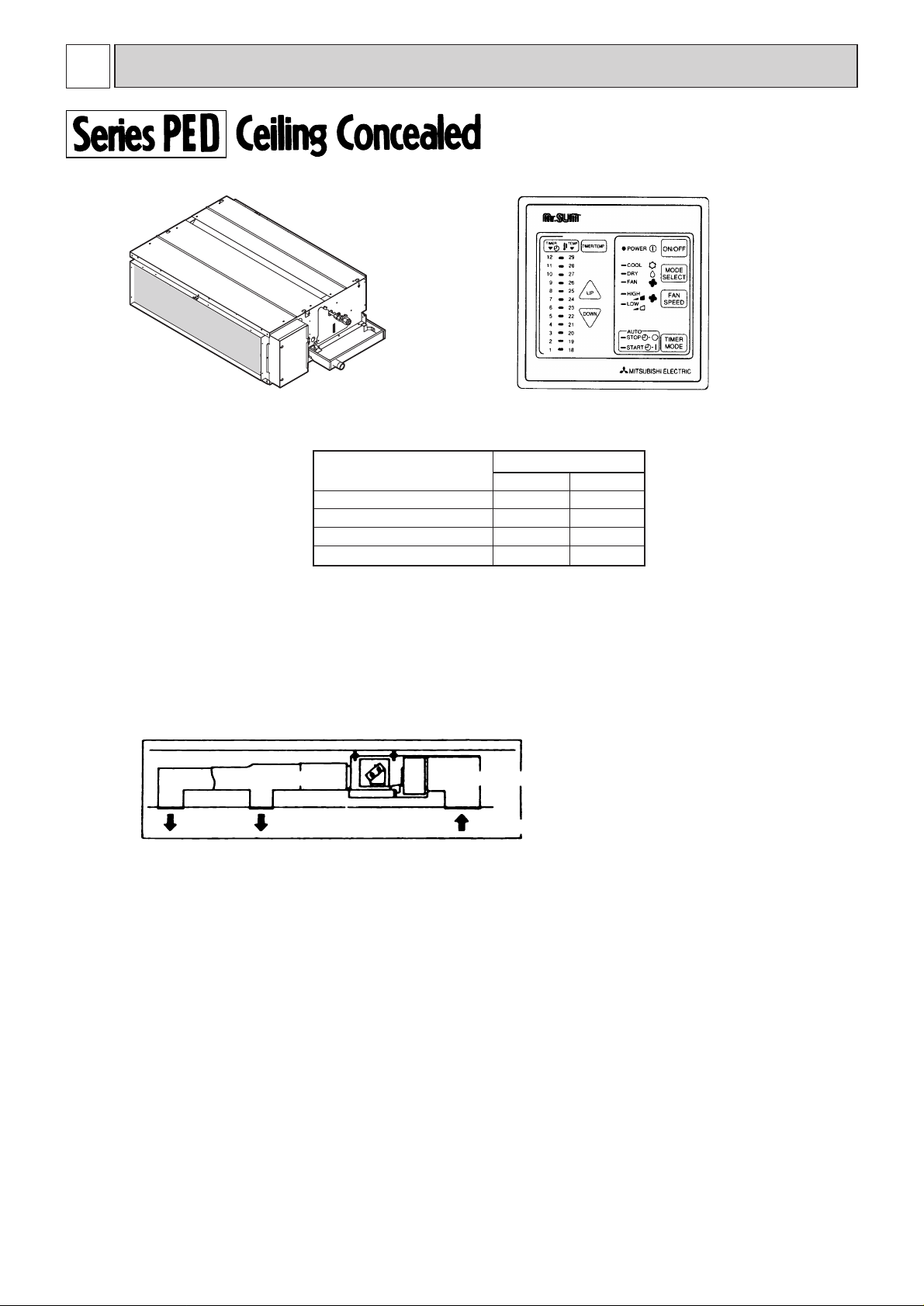
1. TOTALLY INVISIBLE INDOOR UNIT BEHIND THE CEILING
The totally hidden indoor unit that lies above the ceiling surface enables you to utilize full floor space while allowing for
flexible interior design. This new feature is recommended for stores and offices where the user's own imagination is
allowed to be incorporated.
2. MOST SUITABLE FOR SIMULTANEOUS TWO ROOM AIR CONDITIONING
Using air ducts for cooling airflow that matches the structure and purpose of the room, enables you to provide two air
outlets for simultaneous cooling of two rooms.
3. HIGH EXTERNAL STATIC PRESSURE (OPTION MOTOR)
The exceptional external static pressure of 130Pa allows long ducts to be used more extensively to achieve convenient
location of indoor units. (STD:70Pa)
4. DRAIN WATER LIFT-UP MECHANISM (OPTION KIT)
This allows more versatility when selecting drain piping layouts.
air outlet air outlet
Air outlet duct
Air intake duct
air intake
lndoor unit
Remote controller
Models Cooling capacity
W Btu/h
PED-6EJSA.UK 14,800 50,400
PED-3EJA1.UK
PED-4EJSA
1
.UK
PED-5EJSA
1
.UK
7,600
9,700
12,400
25,900
33,100
42,300
Page 3
2
2
PART NAMES AND FUNCTIONS
5. ADVANCED MICROPROCESSOR CONTROL
(1) Ultra - thin 12mm(1/2" )remote controller.
(2) Attractive LED display .
Every operation condition is indicated on the LED display.
(3) Simultaneous display of set temperature and room temperature.
(4) Convenient 12 - hour ON-OFF timer.
This convenient timer allows the unit to be switched on and off automatically,at the time you set. Once the timer is
set,the remaining time is shown on the LED display..
(5) Self - diagnostic function indicates problems instantly on remote controller.
(6) The useful memory feature can store instructions.
The previous set value is memorized so that constant temperature control can be obtained. For example,if a power
failure occurs, this feature will conveniently memorize the previous temperature and reset accordingly.
(7) There is a polar 12 core - conductor cable between the remote controller and indoor board.The cable can be extended
up to 50m.(option)
¡¡
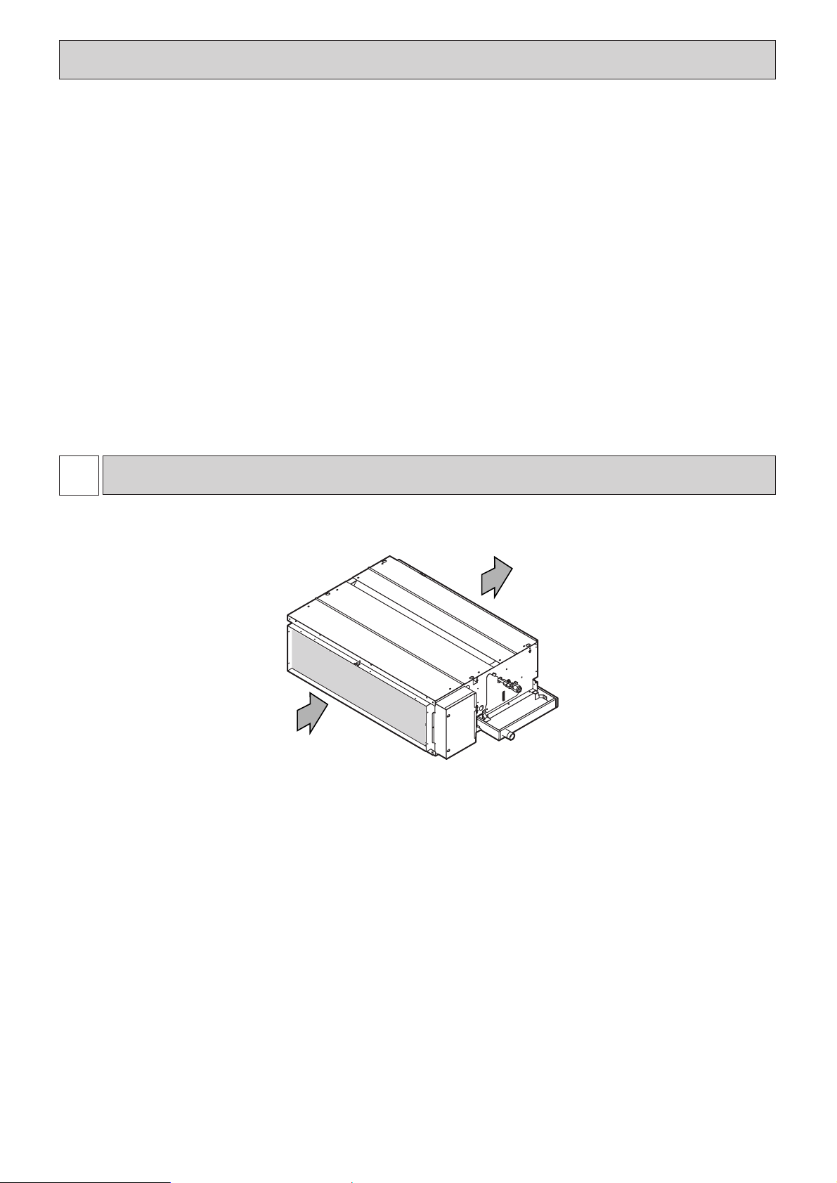
Indoor Unit
Air intake
(sucks the air inside the room into the unit)
Air outlet
Page 4
3
¡¡
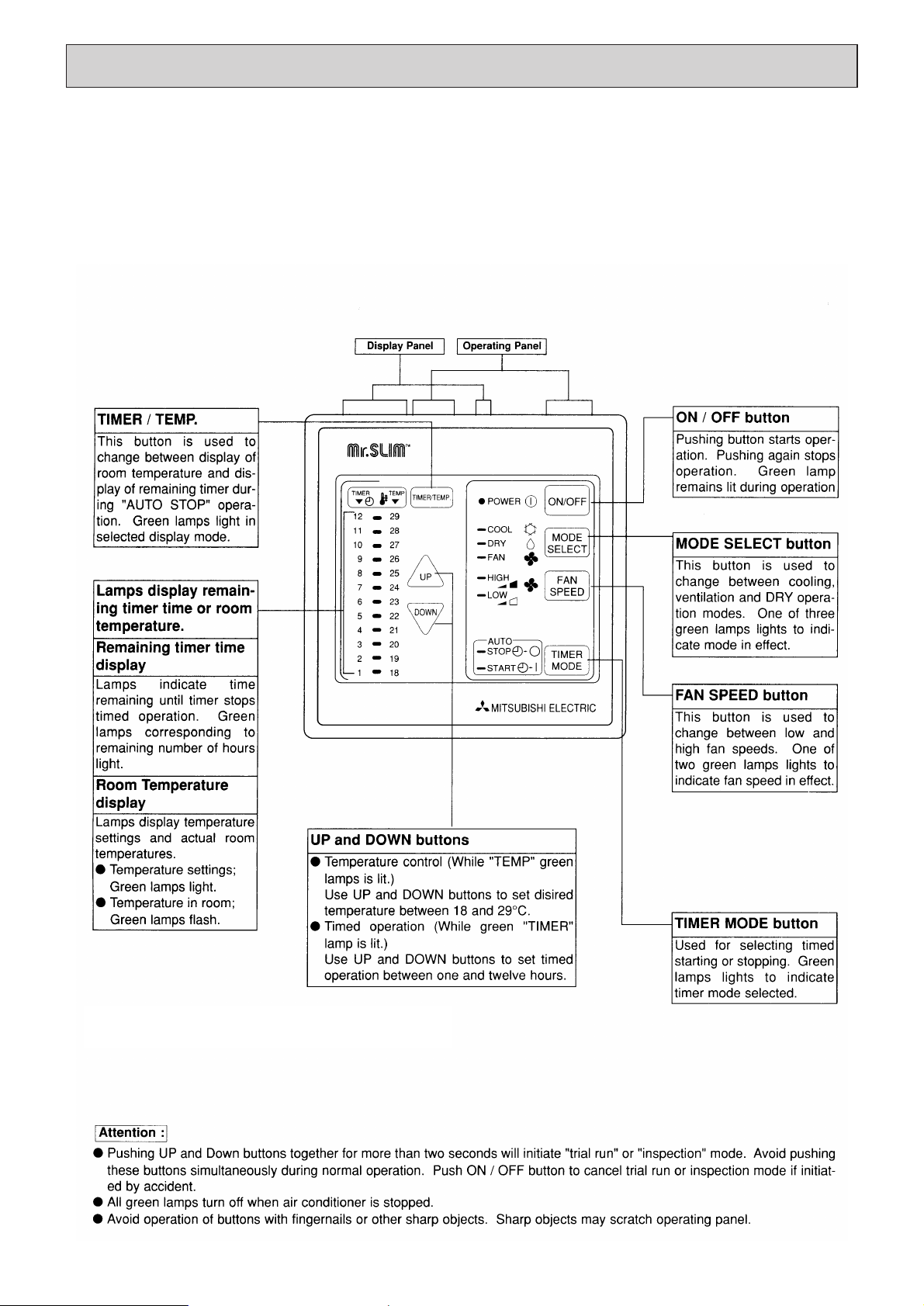
Remote controller
¡ Settings remain in effect until changed. Air
conditioner can be operated by simply pushing
ON/OFF button once settings have been made.
¡¡
Operation buttons
(Example display readings are for explanations only
;actual display readings will differ.
Page 5
4
3
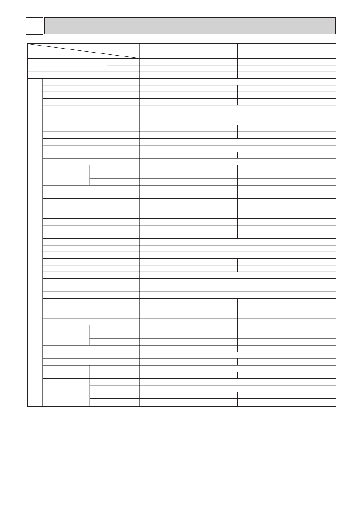
SPECIFICATIONS
Model
PED-4EJSA
1
.UKPED-3EJA1.UK
Item
Cooling capacity
4 Btu/h 33,100
W 9,700
Total input 4 kW 3.98
Power supply
~(1ph),50Hz,220-240V
Input kW 0.62
Running current A 2.64
Starting current A 3.2
External finish
Galvanized sheets
Heat exchanger
Plate fin coil
Plate fin coil
Fan (drive) ~No.
Centrifugal (direct)x2
Fan motor output 1 kW 0.27
Airflow (Low-High) CMM,(CFM)
27- 34(950-1200)
External static pressure 2 Pa(mmAq)
70(7)/130(13) at Hi-notch
Operation control & Thermostat
Remote control&Built-in
Noise level (Low-High)
3, 5 dB (A) 41-46
Cond. drain conn. O.D.
mm, (in)
32(1-1/4)
W mm, (in) 1415(55-11/16)
Dimensions
D mm, (in) 740(29-1/8)
H mm, (in) 325(12-13/16)
Weight
kg, (lbs) 62(137)
Model name
Power supply
Input kW 3.36
Running current A 5.5
Starting current A 38
3.52
16.3
79
External finish
Munsell 5Y 7/1
Refrigerant control
Capillary tube
Compressor
Hermetic
Model NHJ56YDAT
Motor output kW 2.7
Starter type
Line Start
Protection devices
V(L) : Inner thermostat,HP switch,LP switch
Y : Reversed-phase protector,Thermal switch,Thermal relay,HP switch,LP switch
Heat exchanger
Fan (drive) ~No.
Fan motor output kW 0.065+0.065
Airflow CMM,(CFM) 95(3352)
Noise level dB (A) 54
W mm, (in) 870(34-1/4)
Dimensions D mm, (in)
H mm, (in) 1258(49-1/2)
Weight kg, (lbs) 94(207)
Refrigerant
R-22
Charge kg, (lbs) 4.6(10.14)
NH56VNDT
2.7
3.8(8.38)
Pipe size O.D. Liquid mm, (in)
9.52(3/8)
Gas mm, (in)
(m)
(m)
19.05(3/4)
Connection method Indoor side
Flared
Outdoor side
Flared
Between the indoor Height difference 40
& outdoor unit Piping length 40
25,900
7,600
3.60
0.4
1.70
1.9
0.15
20- 25(700-800)
37-41
1175(46-1/8)
740(29-1/8)
325(12-13/16)
44(108)
PU-3YJC.UKPU-3VJC.UK PU-4YJSA.UKPU-4VLJSA.UK
3N~(3ph,4wires)
50Hz
380-415V
~(1ph)
50Hz
220-240V
3.20
5.3
36
3.20
13.9
68
3N~(3ph,4wires)
50Hz
380-415V
~(1ph)
50Hz
220-240V
NHJ52YDAT
2.2
NHJ52VNDT
2.2
Propeller(direct)X1
Propeller(direct)X2
0.085
50(1765)
52
870(34-1/4)
295+24(11-5/8 add 1) 295+24(11-5/8 add 1)
850(33-7/16)
73(161)
2.88(6.35)3.08(6.79)
15.88(5/8)
30
30
1. External static pressure at 130Pa. 4.Rating condition <JIS B 8615>
2. Ex-works at 70Pa(OPTION MOTOR :130Pa) INDOOR : 27˚CDB, 19 ˚CWB
3. External static pressure at 70Pa. OUTDOOR : 35 ˚CDB
5.Noise level : Sound pressure level
INDOOR UNIT
OUTDOOR
UNIT
REFRIGERANT
PIPING
✻
✻
✻
✻✻
✻
✻
✻
✻
✻
✻
Page 6
5
Model
PED-6EJSA.UKPED-5EJSA
1
.UK
Item
Cooling capacity
4 Btu/h 50,400
W 14,800
Total input 4 kW 5.84
Power supply
~(1ph),50Hz,220-240V
Input kW 0.66
Running current A 2.79
Starting current A 6.25
External finish
Galvanized sheets
Heat exchanger
Plate fin coil
Plate fin coil
Fan (drive) ~No.
Centrifugal (direct)x2
Fan motor output 1 kW 0.30
Airflow (Low-High) CMM,(CFM)
36.5- 46(1280-1620)
External static pressure 2 Pa(mmAq)
70(7)/130(13) at Hi-notch
Operation control & Thermostat
Remote control&Built-in
Noise level (Low-High)
3, 5 dB (A) 46-51
Cond. drain conn. O.D.
mm, (in)
32(1-1/4)
W mm, (in) 1715(67-1/2)
Dimensions
D mm, (in) 740(29-1/8)
H mm, (in) 325(12-13/16)
Weight
kg, (lbs) 70(154)
Model name
Power supply
Input kW 5.18
Running current A 8.48
Starting current A 74
External finish
Munsell 5Y 7/1
Refrigerant control
Capillary tube
Compressor
Hermetic
Model ZR72KCTFD
Motor output kW 4.2
Starter type
Line Start
Protection devices
Y : Reversed-phase protector,Thermal switch,Thermal relay,HP switch,LP switch
Heat exchanger
Fan (drive) ~No.
Fan moter output kW 0.065+0.065
Airflow CMM,(CFM) 100(3529)
Noise level dB (A) 56
W mm, (in) 970
Dimensions D mm, (in)
H mm, (in) 1258(49-1/2)
Weight kg, (lbs) 117(258)
Refrigerant
R-22
Charge kg, (lbs) 5.7(12.57)
Pipe size O.D. Liquid mm, (in)
9.52(3/8)
Gas mm, (in)
(m)
(m)
19.05(3/4)
Connection method Indoor side
Flared
Outdoor side
Flared
Between the indoor Height difference 45
& outdoor unit Piping length 45
42,300
12,400
5.3
0.64
2.72
6.0
0.40
33.5- 42(1180-1480)
44-50
1415(55-11/16)
740(29-1/8)
325(12-13/16)
65(143)
PU-5YJSA.UK PU-6YJSA.UK
3N~(3ph,4wires)
50Hz
380-415V
4.66
7.63
65.5
3N~(3ph,4wires)
50Hz
380-415V
ZR61KCTFD
3.5
Propeller(direct)X2
0.065+0.065
100(3529)
55
970
345+24(13-9/16 add 1) 345+24(13-9/16 add 1)
1258(49-1/2)
114(251)
5.1(11.24)
45
45
1. External static pressure at 130Pa. 4.Rating condition < JIS B 8615
>
2. Ex-works at 70Pa(OPTION MOTOR :130Pa) INDOOR : 27 DB, 19 WB
3. External static pressure at 70Pa. OUTDOOR : 35 DB
5.Noise level : Sound pressure level
INDOOR UNIT
OUTDOOR
UNIT
REFRIGERANT
PIPING
✻
✻
✻
✻
✻
✻
✻
✻
✻
✻
✻
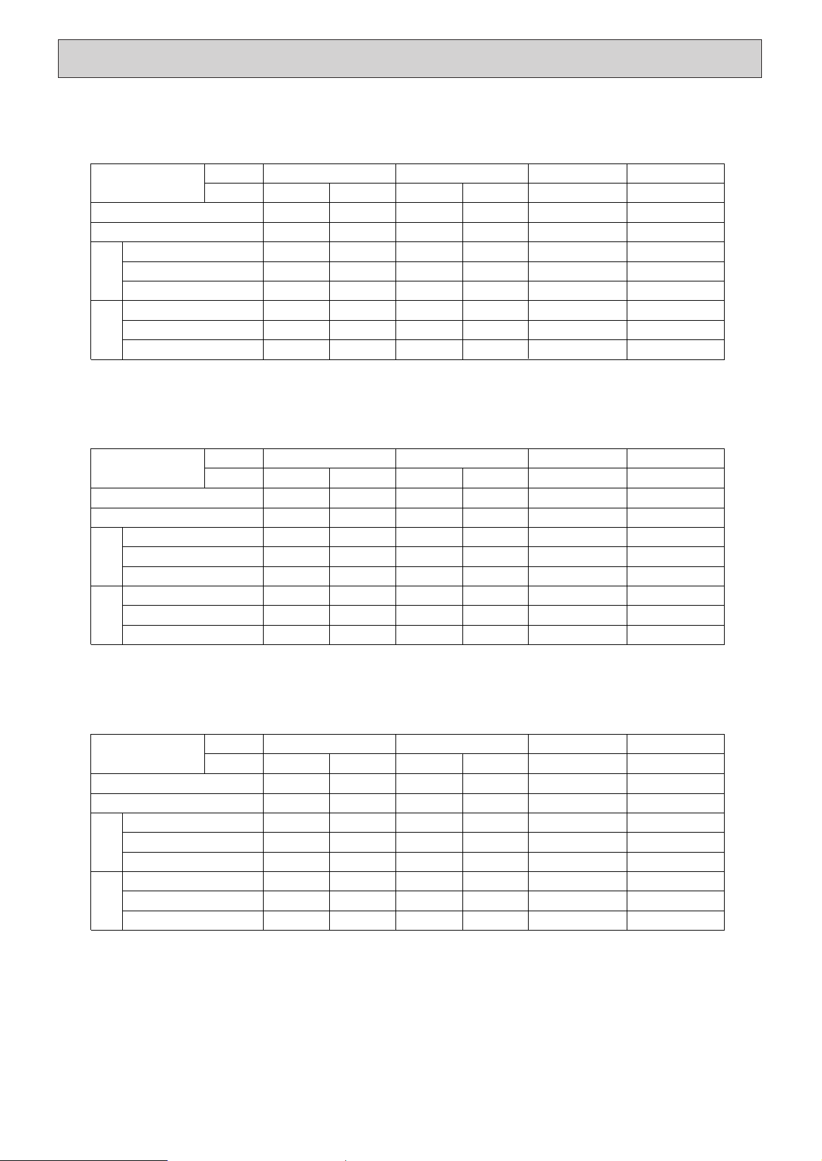
Page 7
6
Service Ref.
Indoor
intake air
WB˚C
20 25 30 35 40 45
CA P.C. CA P.C. CA P.C. CA P.C. CA P.C. CA P.C.
4.73 4.94 5.28 5.64
5.99
6.42
4.83 5.04 5.41 5.78 6.15 6.54
4.90 5.11 5.52 5.91 6.30 6.77
4.99 5.22 5.64 6.05 6.48 7.01
16
18
20
22
1. PERFORMANCE DATA
1) COOLING CAPACITY
Note C A: Capacity(W)
P.C.: Power consumption(kW)
PED6EJSA.UK
Service Ref.
Refrigerant piping length(one way)
5m 10m 15m 20m 25m 30m 35m 40m 45m 50m
2) COOLING CAPACITY CORRECTION FACTORS
12,623 4.29 12,276 4.48 11,780 4.79 11,247 5.12 10,689
5.44
10,118 4.33
13,429 4.38 13,083 4.57 12,549 4.91 12,003 5.25 11,433 5.58 10,851 4.64
14,247 4.45 13,913 4.64 13,367 5.01 12,797 5.36 12,215 5.72 11,619 4.97
15,078 4.53 14,793 4.74 14,223 5.12 13,640 5.49 13,045 5.88 12,425 5.31
16
18
20
22
PED5EJSA1.UK
9,875 3.22 9,603 3.36 9,215 3.60 8,798 3.84 8,361
4.08
7,915 3.24
10,505 3.29 10,234 3.43 9,816 3.69 9,390 3.93 8,943 4.19 8,488 3.48
11,145 3.34 10,883 3.48 10,457 3.76 10,010 4.04 9,555 4.29 9,089 3.73
11,795 3.40 11,572 3.56 11,126 3.84 10,670 4.13 10,204 4.42 9,719 3.99
16
18
20
22
PED4EJSA1.UK
7,737 2.91 7,524 3.04 7,220 3.26 6,893 3.48 6,551
3.69
6,201 2.94
8,231 2.98 8,018 3.10 7,691 3.34 7,357 3.56 7,007 3.79 6,650 3.15
8,732 3.02 8,527 3.16 8,193 3.40 7,843 3.65 7,486 3.88 7,121 3.37
9,241 3.08 9,067 3.22 8,717 3.48 8,360 3.73 7,995 4.00 7,615 3.61
16
18
20
22
PED3EJA1.UK
15,066 14,652 14,060 13,424 12,758 12,076
16,028 15,615 14,978 14,326 13,646 12,951
17,004 16,606 15,954 15,274 14,579 13,868
17,996 17,656 16,976 16,280 15,570 1,4830
PED- 6EJSA.UK
1.00 0.970 0.950 0.931
0.912 0.896 0.880 0.864 0.850 0.840
PED- 5EJSA1.UK
1.00 0.978 0.962 0.948
0.934 0.921
0.908 0.896
0.884 -
PED- 4EJSA1.UK
1.00 0.984 0.974 0.964
0.954 0.944
0.935 0.926
--
PED- 3EJA1.UK
1.00 0.978 0.962 0.948
0.934 0.921
--
--
4
DATA
Page 8
7
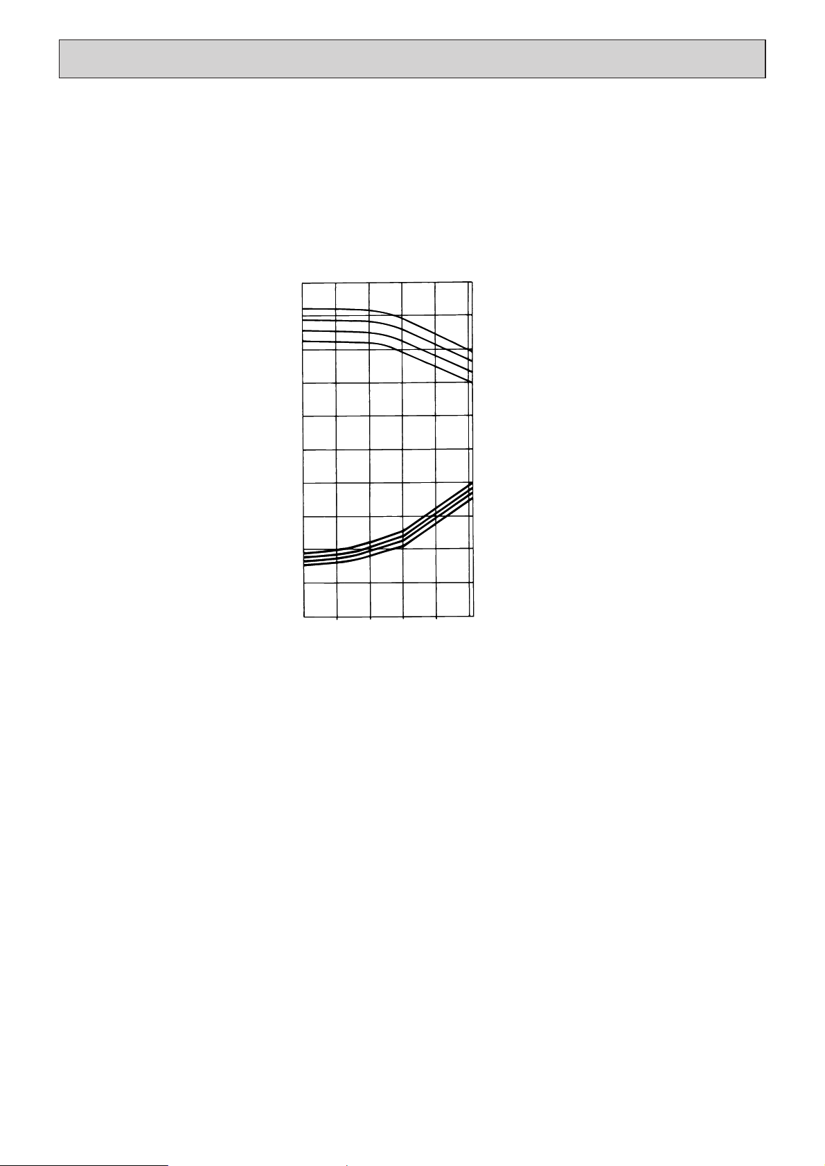
2. PERFORMANCE CURVE (CAPACITY RATIO & TOTAL INPUT RATIO)
Cooling
1.4
1.2
1
0.8
0.6
1.4
1.2
1
0.8
0.6
0.4
22
20
18
16
22
20
18
16
INDOOR WB
(˚C)
INDOOR WB
(˚C)
CAPACITY(RATIO)
TOTAL INPUT(RATIO)
OUTDOOR DB
(˚C)
-5 5 15 25 35 46
PED-3EJA1.UK
PED-4EJSA
1.UK
PED-5EJSA
1.UK
PED-6EJSA.UK
Page 9
8
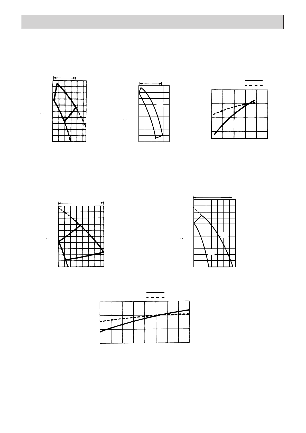
3. FAN PERFORMANCE AND CORRECTED AIR FLOW
Lo
Hi
140
120
100
200
180
160
80
60
40
20
12 16 20 24 28 32
Air flow
(CMM)
PED-3EJA1.UK
Fan performance <130pa>
Recommended range
Extemal static pressure (Pa)
(1Pa 0.1mmAg)
140
120
100
180
160
80
60
40
20
12 16 20 24 28 32
Air flow
(CMM)
Fan performance <70pa>
Recommended range
Extemal static pressure (Pa)
(1Pa 0.1mmAg)
Lo
Hi
Corrected Air Flow
Capacity
Input
1.1
1.0
0.9
0.8
12 16 20 24 28 32
Air flow (CMM)
Correction factor
Cooling
=
=
Lo
Hi
140
120
100
200
180
160
80
60
40
20
26 28 30 32 34 36 38 40
Air flow
(CMM)
PED-4EJSA1.UK
Fan performance <130pa>
Recommended range
Extemal static pressure (Pa)
(1Pa 0.1mmAg)
140
120
100
200
220
180
160
80
60
40
20
24 26 28 30 32 34 36 38
Air flow
(CMM)
Fan performance <70pa>
Recommended range
Extemal static pressure (Pa)
(1Pa 0.1mmAg)
Lo
Hi
Corrected Air Flow
Capacity
Input
1.1
1.0
0.9
0.8
24 26 28 30 32 34 36 38 40
Air flow (CMM)
Correction factor
Cooling
=
=
Page 10

9
Lo
200
220
180
160
140
120
100
80
60
40
20
36 38 40 42 44 46 48 50
Air flow
(CMM)
PED-6EJSA.UK
Fan performance <130pa>
Recommended range
Extemal static pressure (Pa)
(1Pa 0.1mmAg)
52
=
Hi
Corrected Air Flow Capacity
Input
1.1
1.0
0.9
0.8
36 38 40 42 44 46
48 50
52
Air flow (CMM)
Correction factor
Cooling
Lo
Hi
200
180
160
140
120
100
80
60
40
20
36 38 40 42 44 46 48 50
Air flow
(CMM)
Fan performance <70pa>
Recommended range
Extemal static pressure (Pa)
(1Pa 0.1mmAg)
=
Lo
Hi
140
120
100
200
220
180
160
80
60
40
20
32 34 36 38 40 42 44 46 48
Air flow
(CMM)
PED-5EJSA1.UK
Fan performance <130pa>
Recommended range
Extemal static pressure (Pa)
(1Pa 0.1mmAg)
140
120
100
200
220
180
160
80
60
40
20
32 34 36 38 40 42 44 46
Air flow
(CMM)
Fan performance <70pa>
Recommended range
Extemal static pressure (Pa)
(1Pa 0.1mmAg)
Lo
Hi
Corrected Air Flow
Capacity
Input
1.1
1.0
0.9
0.8
32 34 36 38 40 42 44 46 48
Air flow (CMM)
Correction factor
Cooling
=
=
Page 11
10
4. ELECTRICAL DATA
Indoor ····· 220V 50Hz 1phase
Outdoor ··· 220/380V 50Hz 1/3phases
Indoor ····· 230V 50Hz 1phase
Outdoor ··230/400V 50Hz 1/3phases
Indoor ····· 240V 50Hz 1phase
Outdoor ··240/415V 50Hz 1/3phases
PU-5YJSAPU-4YJSA
PED-5EJSA
1
.UKPED-4EJSA1.UK
12,300
5.20
0.59
2.62
5.75
4.61
7.89
65.5
9,600
3.90
0.57
2.53
3.07
3.33
5.6
38
PU-4VLJSA
9,600
4.01
0.57
2.53
3.07
3.44
16.6
79
PU-3YJA
PED-3EJA1.UK
7,500
3.55
0.35
1.55
1.82
3.20
5.5
36
PU-3VJA
7,500
3.55
0.35
1.55
1.82
3.20
14.5
68
PU-6YJSA
PED-6EJSA.UK
14,700
5.76
0.61
2.69
6.00
5.15
8.56
74
PU-5YJSAPU-4YJSA
PED-5EJSA
1
.UKPED-4EJSA1.UK
12,400
5.30
0.64
2.72
6.00
4.66
7.63
65.5
9,700
3.98
0.62
2.64
3.20
3.36
5.5
38
PU-4VLJSA
9,700
4.14
0.62
2.64
3.20
3.52
16.3
79
PU-3YJA
PED-3EJA
1
.UK
7,600
3.60
0.40
1.70
1.90
3.20
5.3
36
PU-3VJA
7,600
3.60
0.40
1.70
1.90
3.20
13.9
68
PU-6YJSA
PED-6EJSA.UK
14,800
5.84
0.66
2.79
6.25
5.18
8.48
74
PU-5YJSAPU-4YJSA
PED-5EJSA
1
.UKPED-4EJSA1.UK
12,200
5.10
0.54
2.50
5.50
4.56
8.15
65.5
9,500
3.81
0.52
2.41
2.93
3.29
5.7
38
PU-4VLJSA
9,500
3.87
0.52
2.41
2.93
3.35
16.9
79
PU-3YJA
PED-3EJA
1
.UK
7,400
3.48
0.30
1.39
1.74
3.18
5.7
36
PU-3VJA
7,400
3.48
0.30
1.39
1.74
3.18
15.1
68
PU-6YJSA
PED-6EJSA.UK
14,600
5.67
0.56
2.59
5.75
5.11
8.63
74
Models
Indoor
Outdoor
Capacity(W)
Total input(kW)
Input(kW)
Current(A)
Starting current(A)
Input(kW)
Current(A)
Starting current(A)
IndoorOutdoor
Models
Indoor
Outdoor
Capacity(W)
Total input(kW)
Input(kW)
Current(A)
Starting current(A)
Input(kW)
Current(A)
Starting current(A)
IndoorOutdoor
Models
Indoor
Outdoor
Capacity(W)
Total input(kW)
Input(kW)
Current(A)
Starting current(A)
Input(kW)
Current(A)
Starting current(A)
IndoorOutdoor
Page 12
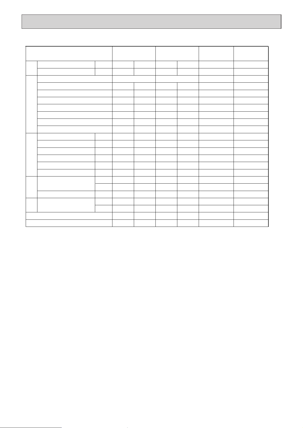
11
Models
TotalElectrical circuitRefrigerant circuit
Indoor side
Outdoor
side
SHF
BF
Capacity
Input
Indoor unit model
Phase Hz
Volts
Amperes
Outdoor unit-model
Phase,Hz
Volts
Amperes
W
kW
Discharge pressure
Suction pressure
Discharge temperature
Condensing temperature
Suction temperature
Ref.Pipe length
Intake air temperature
Intake air temperature
Diischarge air temperature
MPa
MPa
˚C
˚C
˚C
m
DB˚C
WB˚C
DB˚C
DB˚C
WB˚C
5. STANDARD OPERATION DATA (COOLING)
PED-5EJSA1.UK
12,400
5.30
PED-5EJSA
1
1.50
240
2.72
PU-5YJSAPU-4YJSA
3.50
415
7.63
1.84
0.40
82.9
49.3
0.3
5
27.0
19.0
15.5
35.0
24.0
0.85
0.13
9,700
4.14
1.50
240
2.64
PU-4VLJSA
1.50
240
16.3
1.80
0.52
82.1
48.5
8.1
5
27.0
19.0
15.7
35.0
24.0
0.80
0.22
9,700
3.98
1.50
240
2.64
3.50
415
5.5
1.81
0.52
74.0
48.7
8.5
5
27.0
19.0
16.0
35.0
24.0
0.80
0.22
PED-6EJSA.UKPED-4EJSA
1
.UK
14,800
5.88
PED-6EJSAPED-4EJSA
1
PU-3YJC
7,600
3.60
1.50
240
1.70
PU-3VJC
1.50
240
13.9
2.03
0.50
62.2
53.6
9.4
5
27.0
19.0
15.5
35.0
24.0
0.78
0.21
7,600
3.60
1.50
240
1.70
3.50
415
5.3
2.02
0.49
79.1
53.3
9.0
5
27.0
19.0
14.8
35.0
24.0
0.78
0.20
PED-3EJA
1
.UK
PED-3EJA
1
1.50
240
2.79
PU-6YJSA
3.50
415
8.47
2.07
0.46
78.3
53.6
4.3
5
27.0
19.0
13.6
35.0
24.0
0.74
0.14
Page 13
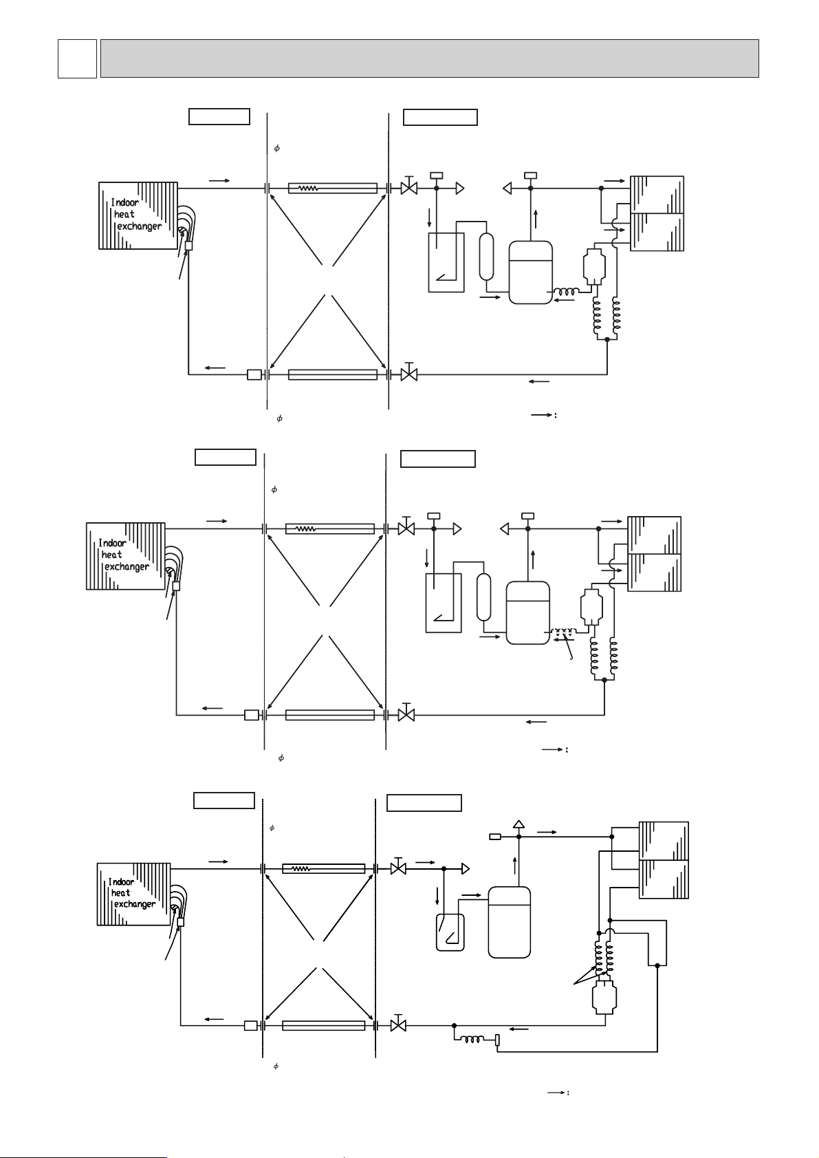
12
5
REFRIGERANT SYSTEM DIAGRAM
PED-3EJA1.UK
PED-4EJSA
1.UK
PED-5EJSA
1.UK
Strainer
Strainer
Strainer
Refrigerant pipe
(option)
9.52mm(3/8)
(With heat insulator)
Refrigerant pipe
(option)
9.52mm(3/8)
(With heat insulator)
Refrigerant pipe
(option)
9.52mm(3/8)
(With heat insulator)
Ball valve
(With service port)
Ball valve
(With service port)
Ball valve
(With service port)
Capillary tube
Capillary tube
Capillary tube
Capillary tube
Capillary tube
O.D.4.0XI.D.2.4-L=400
(O.D.4.0XI.D.2.4-L=840)X2pcs
(O.D.3.2XI.D.2.0-L=840)X2pcs
(O.D.3.2XI.D.1.8-L=800)X2pcs
PU-3YJC(O.D.3.2XI.D.1.4-L=800)
PU-3VJC(O.D.3.2XI.D.2.0-L=500)
Strainer
Strainer
Strainer
Compressor
Compressor
Compressor
Outdoor heat
exchanger
Outdoor heat
exchanger
Outdoor heat
exchanger
Check
plug
Check
plug
Check
plug
High pressure
switch
High pressure
switch
High pressure
switch
Low pressure
switch
Low pressure
switch
Charge
plug
Charge
plug
Charge
plug
Accumulator
Accumulator
Ball
valve
Ball
valve
Ball
valve
Flexible tube
Flexible tube
Flexible tube
Flared
connection
Flared
connection
Flared
connection
Thermistor
RT2
Thermistor
RT2
Thermistor
RT2
Distributor
Distributor
Distributor
Refrigerant pipe
(option)
19.05mm(3/4)
(With heat insulator)
Refrigerant pipe
(option)
19.05mm(3/4)
(With heat insulator)
Refrigerant pipe
(option)
15.88mm(5/8)
(With heat insulator)
PU-5YJSA2.UK
PU-4Y(VL)JSA2.UK
PU-3V(Y)JC.UK
flow of refrigerant
flow of refrigerant
flow of refrigerant
Capillary tube for
injection
Only PU-4YJSA(O.D.3.2XI.D.1.2-L=500)
*1
*1
Indoor unit
Indoor unit
Indoor unit
Outdoor unit
Outdoor unit
Outdoor unit
Page 14
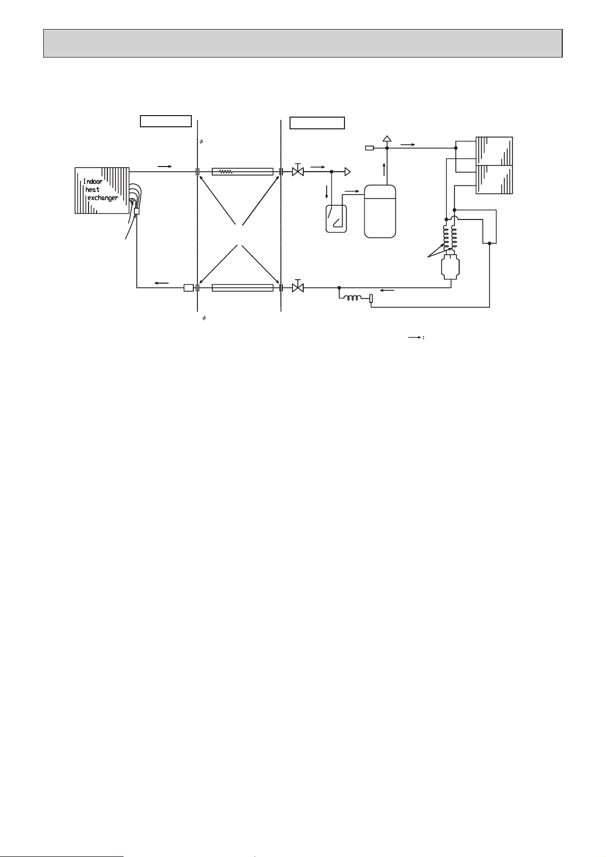
13
PED-6EJSA.UK
Strainer
Refrigerant pipe
(option)
9.52mm(3/8)
(With heat insulator)
Ball valve
(With service port)
Capillary tube
Capillary tube
O.D.4.0XI.D.2.4-L=200
(O.D.4.0XI.D.2.4-L=1200)X2pcs
Strainer
Compressor
Outdoor heat
exchanger
Check
plug
High pressure
switch
Charge
plug
Accumulator
Ball
valve
Flexible tube
Flared
connection
Thermistor
RT2
Distributor
Refrigerant pipe
(option)
19.05mm(3/4)
(With heat insulator)
PU-6YJSA.UK
flow of refrigerant
Indoor unit
Outdoor unit
Page 15

14
6
OUTLINES & DIMENSIONS
1. INDOOR UNIT
210
12-ø3
450
450
140
282
680
3 3
30
319
261
181 40
30
A
C B 81
10
375
10
80
C B 81
A
E 13
30
D
20
35
30
1053 169
307
113
122
12-ø3
(14x22)
Lifting bolt hole
45
163
323
308
44 75
6
5
13
Keep duct-work length 850mm or more.
Be sure to apply the air filter (field supply) near the air inlet grille.
Service space:500 or more
81
365~465
197
81
50~150
55
Access door
Air outlet
Air inlet
3
1
2
4
1 Refrigerant piping flare connection (liquid ø9.52 copper tube) : HP
2 Refrigerant piping flare connection (gas øF copper tube) : LP
3 Drain 25A (male screw)
4 Electrical parts box
5 Drain Pump (Option)
6 Drain Pipe (Option)···Use VP25 (O.D.ø32 PVC TUBE)
)
Set
Model
PED-3
PED-4·5
PED-6
A
1012
1252
1552
B
280
360
460
C
290
370
470
D
1070
1310
1610
E
1044
1284
1584
F
15.88
19.05
19.05
2. REMOTE CONTROLLER
PED-3EJA1.UK
PED-4EJSA
1.UK
PED-5EJSA
1.UK
PED-6EJSA.UK
Page 16

15
31
312
3124321
3
2
1
321
13 137
Drain sensor
Drain pump
Drain sensor connector
Drain pump connector
*
DS
*
DP
CN50
CNP
fig:*1
220V
230V
220 RED
230 ORANGE
240 YELLOW
NOTES
1.Since the indoor transfomer(T) is connected with 240V power. if 220,230V
power is used, Change the wiring connection shown in fig:
*
1
When power supply is
(indoor/outdoor connecting line)Terminal block
NAME
NAME NAME
SYMBOL EXPLANATION(
*
···· Option parts)
LD3<R.B>
F1,2<I.B>
CNR120<R.B>
CN51<I.B>
Connector (remote controller)
Capacitor (fan motor)
C
SYMBOL
LD5<R.B>
Auxiliary relay (fan motor)X5,X6(I.B)
Thermistor (pipe temperature sensor
0˚C/15kΩ.25˚C/5.4kΩ)
Terminal block (power)TB1
SYMBOL
SYMBOL
LD4<R.B>
CN120<I.B>
I.B
TB2
ZNR<I.B>
T
RT1
RT2
Indoor controller board
Fuse <6.3A>
Varistor
Transformer
X1(I.B) Auxiliary relay (drain pump)
Thermistor (room temperature sensor
0˚C/15kΩ.25˚C/5.4kΩ)
LD7<R.B>
LD8<R.B>
LD1<R.B>
Run indicator LED
Connector (centrally control)
Connector (remote controller)
Cooling indicator LED
Fan mode indicator LED
Fan high indicator LED
Indicator mode temperature LED
Indicator mode timer LED
LD12<R.B>
LD11<R.B>
LD10<R.B>
LD9<R.B>
Dry indicator LED
Fan low indicator LED
Off timer indicator LED
On timer indicator LED
LD13-24
<R.B>
Temperature/Timer remaining
time indicator LED
MF Indoor Fan motor
Function switchSW1(I.B)
SW2(I.B) Unit switch
SW3(I.B) Emergency operation switch
SW1(R.B) ON/OFF switch
SW2(R.B) Operation mode switch
SW3(R.B) Fan hige/low switch
SW5(R.B) Indicator switch
SW6(R.B) Temperature and timer setting up switch
SW7(R.B) Temperature and timer setting down switch
SW8(R.B) Timer continuous ON/OFF switch
R.B Remote controller board
GRN/YLW
BRN
BRN
BLU
BLK
BLK
GRY
GRY
YLW
GRN/YLW
BLU
RED
ORN
YLW
GRN/YLW
BLU
BLK
RED
WHT
WHT
ORN
YLW
WHT
RED
AC10.6V
AC14.5V
BRN
RED
TRANSMISSION WIRES
12VDC 12CORE CONNECTOR
TO OUTDOOR UNIT
CONNECTING WIRES
12VDC(non - polar)
CN31
HEATER
CN51
MULTIPLE
BLU
2
1
4321
DS
43 1
OFF
ON
SW5
SW8
SW3
SW2
ON
OFF
SW1
R.B
SW3
I.B
CN50
DRAIN
CN21
PIPE
CN20
INTAKE
1122
2
5
RT2
RT1
SW2
SW1
31
CND
POWER
OFF
ON
LD8 LD7
LD13
LD14
LD15
LD16
LD17
LD18
LD19
LD20
LD21
LD22
LD23
LD24
LD1
LD3
LD9
LD4
LD5
LD10
LD11
LD12
SW6
SW7
NOTES
[Check items]
(1)
(2)
[Emergency operation procedure]
MODELS: PED-3EJA1, PED-4EJSA1, PED-5EJSA1, PED-6EJSA WIRING DIAGRAM
X6X1 X5
ZNR
F2
T
CN4T
TRANS
CNT
TRANS
FAN1
F1
:OPTION PARTS
pressure 130Pa
External static
pressure 70Pa
External static
WHITE
RED
24 23
C
53 61
MF
DP
PE
BREAKER
TO DUCT
TB2
CN30
OUTDOOR
CN120
TO RC
TB1
N
L
POWER SUPPLY
~(1phase)
220 - 240VAC 50Hz
C
5461
MF
CNR120
Since the outdoor side electric wiring may change be sure
to check the outdoor unit electric wiring for servicing.
Symbols used in circuit diagram above are, :Terminal
block, :connector.
Emergency operation
If trouble occurs with either the remote controller or the
indoor microcomputer and no other trouble exists,emergency operation for cooling can be performed by changing
the setting of dip switch(SW3<I.B>)on the indoor controller
board (emergency dry operation is not possible).
Make sure that no other trouble exists with the outdoor unit.Trouble
with the outdoor unit prevents emergency operation.
(If any trouble exists with the outdoor unit, the trouble location will
be displayed on the remote controller and the trouble position will
be shown on the outdoor controller board LED.See electric circuit
diagram of the outdoor unit for details.)
Make sure that there is no trouble with the indoor fan.
Emergency operation will be a continuous run with operation by the
power ON/OFF(ON/OFFwith the remote controller is not possible).
Set the dip switch(SW3<I.B>)on the indoor controller board to 1 ·
2 on and 3 off for cooling.
Turn on the outdoor unit side circuit breaker.
During emergency operation indoor fan runs at High speed.
Thermostat will not function.Cold air blows out for defrosting during
heating thus do not operate defrosting for a long time.
Emergency cooling should be limited to 10 hours maximum(the
indoor unit heat exchanger may freeze).
(1)
(2)
(3)
(4)
(5)
1.
2.
3.
7
WIRING DIAGRAM
Page 17

16
8
DISASSEMBLY INSTRUCTIONS
Disconnect
the fan motor connecter
Drain pan
catches (Hidden)
Drain pan
catches (Hidden)
Filter
Bottom plate
Drain pan
Heat exchanger
Bottom plate
assembly
1
2
A
Figure1.
!!
. Removing the fan motor
1. Removing the 9 screws that fix the bottom plate A, and
remove it.
2. Removing the drain pan as follows:
(1) Remove the screw that fixes the drain pan.
(2) Slide the drain pan in the direction 1, Figure1 and
unhook the drain pan catch near the drain pipe.
(3) Slide the drain pan in the direction 2, Figure1 and
unhook the 2 catches on the other side of the drain
pipe.
3. Remove the 8 screws that fix the bottom plate
assembly, and remove it.
4. Disconnect the fan motor connector from the controller
box.
5. Remove the fan plate as follow:
Figure2.
(1)Remove the 4 screws 1
(2)Slide down the fan plate to remove.
6. Remove the sirocco fan setting screw and the motor
fixture setting screw to remove the motor fixture.
Remove the other motor fixture as well, and then remove
the fan motor.
1
1
Fan base
Page 18

17
Figure3.
Fan base
Sirocco fan
Sirocco fan
Housing assembly
Housing
assembly
Piece
Piece
Leg
Bush
Bush
Motor
Motor base
(Only PED-3)
Page 19

18
@@
. Removing the drain water lift-up pump
1. Remove the drain pan. (Refer 1- 2.)
2. Disconnect the drain pump connector and drain sensor
connector from the controller box.
3. Remove the two screws of the pump cover assembly.
4. Remove the drain hose from drain socket.
5. Remove the three screws of the drain pump assembly.
6. Remove the earth screw and four nuts of the drain
pump assembly.
7. Remove the drain pump from drain pump assembly.
Figure4.
Pump cover
Drain socket
assembly
Drain pump
assembly
Drain hose
Rubber plug
Drain pan cover
1
2
Drain pan
Page 20

19
9
PARTS LIST
14.15.16
1.2.3
11.12.13
4.5.6
7.8.9.10
No.
1
2
3
4
5
6
7
8
9
10
11
12
13
14
15
16
Part No. Part Name Drawing No.
Qt'y/set
Spec.
W631101Z04
W631188G02
W264221G03
W631186G01
W630129G01
Bottom plate 1
W634050Z01Bottom plate 1
W634028Z01Bottom plate 1
Bottom plate 2 ass'y
W634030G01Bottom plate 2 ass'y
W634052G01Bottom plate 2 ass'y
H.EX.General ass'y
W262881G03H.EX.General ass'y
W262863G06H.EX.General ass'y
W262863G05H.EX.General ass'y
Drain pan ass'y
W634034G01Drain pan ass'y
W634056G01Drain pan ass'y
Filter
W611960G04
Filter
W611960G05
Filter
PED-
6EJSA
PED-
5EJSA
PED-
4EJSA
PED3EJA
1
1
1
1
1
1
1
1
1
1
1
1
1
1
1
1
1
1
1
1
PED-3EJA1.UK
PED-4EJSA
1.UK
PED-5EJSA
1.UK
PED-6EJSA.UK
EXTERNAL PARTS
Page 21

20
8
9
2
1
2
1.17
6.7
6.7
10.11.12
15.16
13.14
9
8
3.4.5
18
No.
1
2
3
4
5
6
7
8
9
10
11
12
13
14
15
16
17
18
Part No. Part Name Drawing No.
PED-
6EJSA
Qt'y/set
with a nut
20-25L
R02K338H02 222
22
22
222
2
2
2
2
22
2
1
1
1
1
11
1
1
1
1
1
1
2
2
2
1
1
2
R02K338G82
W631187G01
W860050H02
W631126G01
W631120G01
P714614X01
W631122Z04
P412223X01
<MF>250W,1Phase
<MF>240W,1Phase
220~240V
220~240V
220~240V
<C>
R60 508 131
Piece
Piece
Fan base ass'y
W634036G01Fan base ass'y
W634058G01Fan base ass'y
Bush
Sirocco fan
Housing ass'y
Motor
P714659X01Motor
P714661X01Motor
Leg
Capacitor 16
P412172X01
Capacitor 6
R60 508 132
R61 Y01 104
W491760H02BushR61 766 104
R61 Y17 221
R61 Y21 221
R61 Y20 221
W241060H03Motor supportR61 652 130
W353715H01AttachmentR61 652 131
W634069Z01Motor base
PED-
5EJSA
PED-
4EJSA
PED3EJA
: Not illustrated
<MF>150W,1Phase
✽
✽
PED-3EJA1.UK
PED-4EJSA
1.UK
PED-5EJSA
1.UK
PED-6EJSA.UK
BLOWER PARTS
Page 22

21
6
5
3
4
7
2
1
7
No.
1
2
3
4
5
6
7
8
9
10
Part No. Part Name Drawing No.
P436109X01
P436110X01
BG00L760G22
BG65T178H03
BG71V161H04
BG71V162H08
P419114X01
PED-
6EJSA
Qt'y/set
Spec.
<TB2>
<TB1>
<I.B.>
<T>
<RT1>
<RT2>
R61 978 247 Terminalbed
Terminalbed
Controller
Transformer
Thermistor S
Thermistor H
Ferrite core
R61 979 247
PED-
5EJSA
PED-
4EJSA
PED3EJA
1111
1111
1111
1111
1111
1111
2222
PED-3EJA1.UK
PED-4EJSA
1.UK
PED-5EJSA
1.UK
PED-6EJSA.UK
CONTROL BOX PARTS
Page 23

22
1
2
3
No.
1
2
3
4
5
Part No. Part Name Drawing No.
BC00C006G34
BG00K507G02
BG78R190G10
Qt'y/set
Spec.
J controller
10m
0.5m
Remote controller
Remote controller cable
Cable ( for board )
1111
1111
1111
PED-
6EJSA
PED-
5EJSA
PED-
4EJSA
PED3EJA
PED-3EJA1.UK
PED-4EJSA
1.UK
PED-5EJSA
1.UK
PED-6EJSA.UK
ELECTRICAL PARTS
Page 24

23
3
4
1.2
5
No.
1
2
3
4
5
Part No. Part Name Drawing No.
BG56J144G13
DB26F111H03
BB00P145G17
DE00H343G21
P312040X01
Qt'y/set
Spec.
Drain pump-94
Cushion
Drain socket ass'y
Drain sensor ass'y
Rubber plug
R61 E96 558
PED-
6EJSA
PED-
5EJSA
PED-
4EJSA
PED3EJA
1111
4444
1111
1111
1111
PED-3EJA1.UK
PED-4EJSA
1.UK
PED-5EJSA
1.UK
PED-6EJSA.UK
DRAIN WATER LIFT-UP PUMP PARTS
Page 25

24
10
OPERATION FLOW-CHART
PED-3EJA1.UK
PED-4EJSA
1.UK
PED-5EJSA
1.UK
PED-6EJSA.UK
Page 26

252627
Page 27

Page 28

Page 29

28
11
MICROPROCESSOR CONTROL
Page 30

29
l
Page 31

30
l
Page 32

31
l
l
after
Page 33

323334
Page 34

Page 35

12
TROUBLE SHOOTING
Page 36

35
Page 37

36
PED-4EJSA1.UK,PED-5EJSA1.UK,PED-6EJSA.UK
PED-3EJA1.UK
PAC-05FFS-E
PAC-07FFS-E
PAC-10FFS-E
PAC-15FFS-E
15.88
13
OPTIONAL PARTS
Page 38

373839
Page 39

Page 40

wrap
wrap
wrap
Page 41

40
s
Page 42

41
1
5
Power
supply
BRN
RED
ORN
YRW
GRN
BRN
RED
ORN
YRW
GRN
JST
XHP3
<Wiring>
CN51
connector(5P)
Optional multiple
display adaptor
The maximum distance between
indoor board and relay is 10m.
Wiring at the actual
place
Electrical insulation is needed.
BROWN
RED
ORANGE
YELLOW
GREEN
X1
X2
Page 43

42
8. OPTIONAL MOTOR
The external static pressure of 130Pa allows long ducts to be used more extensively to enable the most convenient
positioning of indoor units.
9. DRAIN WATER LIFT-UP MECHANISM
This allows more versatility when selecting drain piping layouts.
Part No. PAC-SK005MT-F
PAC-SK004MT-F
PAC-SK003MT-F
PED-3EJA
1
.UK
PED-4EJSA
1
.UK
PED-5EJSA
1
.UK, PED-6EJSA.UK
Applied model
Part No. PAC-SK001DM-F
PED-3EJA
1
.UK, PED-6EJSA.UK
Applied model
Page 44

HEAD OFFICE MITSUBISHI DENKI BLDG. MARUNOUCHI TOKYO100 TELEX J24532 CABLE MELCO TOKYO
MEE99K001
Issued in July. 1999
Printed in Japan
New publication, effective July. 1999
Specifications subject to change without notice.
TM
 Loading...