

Mitsubishi Electric PDFY-10NMU-A, PDFY-32NMU-A, PDFY-16NMU-A, PDFY-40NMU-A, PDFY-24NMU-A Service Manual
...
TECHNICAL & SERVICE MANUAL
<Indoor unit>
PDFY-10NMU-A,PDFY-16NMU-A
PDFY-24NMU-A,PDFY-32NMU-A
PDFY-40NMU-A,PDFY-48NMU-A
2002
Models
Ceiling Concealed Built-in
Series PDFY
CONTENTS
SAFETY PRECAUTIONS·························1
1. FEATURES············································2
2. PART NAMES AND FUNCTIONS········3
3. SPECIFICATION ···································5
4. OUTLINES AND DIMENSIONS············7
95.WIRING DIAGRAM ·······························
6.
REFRIGERANT SYSTEM DIAGRAM
····11
7.TROUBLE SHOOTING························12
8. DISASSEMBLY PROCEDURE···········17
For use with the R22
AIR CONDITIONERS CITY MULTI

1
- Inadequate connection and fastening may generate heat and
cause a fire.
• Prepare for typhoons and other strong winds and earthquakes
and install the unit at the specified place.
- Improper installation may cause the unit to topple and result in
injury.
• Always use an air cleaner , humidifier, electric heater, and other
accessories specified by Mitsubishi Electric.
- Ask an authorized technician to install the accessories. Improper
installation by the user may result in water leakage, electric shock,
or fire.
• Never repair the unit. If the air conditioner must be repaired,
consult the dealer.
- If the unit is repaired improperly , water leakage , electric shoc k, or
fire may result.
• Do not touch the heat exchanger fins.
- Improper handling may result in injury.
• If refrigerant gas leaks during installation work, ventilate the
room.
- If the refrigerant gas comes into contact with a flame, poisonous
gases will be released.
• Install the air conditioner according to this Installation Manual.
- If the unit is installed improperly , water leakage , electric shock, or
fire may result.
• Have all electric work done by a licensed electrician according
to “Electric Facility Engineering Standard” and “Interior Wire
Regulations”and the instructions given in this manual and always use a special circuit.
- If the power source capacity is inadequate or electric work is per-
formed improperly, electric shock and fire may result.
• Securely install the cover of control box and the panel.
- If the cover and panel are not installed properly, dust or water
may enter the outdoor unit and fire or electric shock may result.
• When installing and moving the air conditioner to another site,
do not charge the it with a refrigerant different from the refrigerant (
- If a different refrigerant or air is mixed with the original refrigerant,
the refrigerant cycle may malfunction and the unit may be damaged.
• If the air conditioner is installed in a small room, measures
must be taken to prevent the refrigerant concentration from
exceeding the safety limit even if the refrigerant should leak.
- Consult the dealer regarding the appropriate measures to pre-
vent the safety limit from being exceeded. Should the refrigerant
leak and cause the safety limit to be exceeded, hazards due to
lack of oxygen in the room could result.
• When moving and reinstalling the air conditioner, consult the
dealer or an authorized technician.
- If the air conditioner is installed improperly, water leakage, elec-
tric shock, or fire may result.
• After completing installation work, make sure that refrigerant
gas is not leaking.
- If the refrigerant gas leaks and is exposed to a fan heater, stove,
oven, or other heat source, it may generate noxious gases.
• Do not reconstruct or change the settings of the protection
devices.
- If the pressure switch, thermal switch, or other protection device
is shorted and operated forcibly , or parts other than those specified
by Mitsubishi Electric are used, fire or explosion may result.
1. Before installation and electric work
s Before installing the unit, make sure you read all the
“Safety precautions”.
s The “Safety precautions” provide very important
points regarding safety. Make sure you follow them.
s This equipment may not be applicable to EN61000-3-
2: 1995 and EN61000-3-3: 1995.
s
s Please report to or take consent by the supply au-
thority before connection to the system.
Symbols used in the text
Warning:
Describes precautions that should be observed to prevent danger
of injury or death to the user.
Caution:
Describes precautions that should be observed to prevent damage
to the unit.
Symbols used in the illustrations
: Indicates an action that must be avoided.
: Indicates that important instructions must be followed.
: Indicates a part which must be grounded.
: Indicates that caution should be taken with rotating parts. (This
symbol is displayed on the main unit label.) <Color: Yellow>
: Beware of electric shock (This symbol is displayed on the main
unit label.) <Color: Yellow>
Warning:
Carefully read the labels affixed to the main unit.
Warning:
• Ask the dealer or an authorized technician to install the air conditioner.
- Improper installation by the user may result in water leakage, elec-
tric shock, or fire.
• Install the air unit at a place that can withstand its weight.
- Inadequate strength may cause the unit to fall down, resulting in
injuries.
• Use the specified cables for wiring. Make the connections securely so that the outside force of the cable is not applied to the
terminals.
This equipment may have an adverse effect equipment on the same electrical supply system.
R22) specified on the unit.
• When handling this product, always wear protective equipment.
EG : Gloves, full arm protection namely boiler suit, and safety glasses.
- Improper handling may result in injury.
SAFETY PRECAUTIONS
2
PDFY-10NMU-A
PDFY-16NMU-A
PDFY-24NMU-A
PDFY-32NMU-A
PDFY-40NMU-A
PDFY-48NMU-A
2.8 / 3.2
4.6 / 5.5
6.9 / 7.4
9.1 / 10
11.9 / 13.2
13.6 / 15.0
Ceiling Concealed Built-in
Series PDFY
Models
Cooling capacity/Heating capacity
kW
9500 / 10800
15700 / 18700
23600 / 25400
31000 / 34000
40500 / 45000
46500 / 51000
Btu / h
FEATURES1
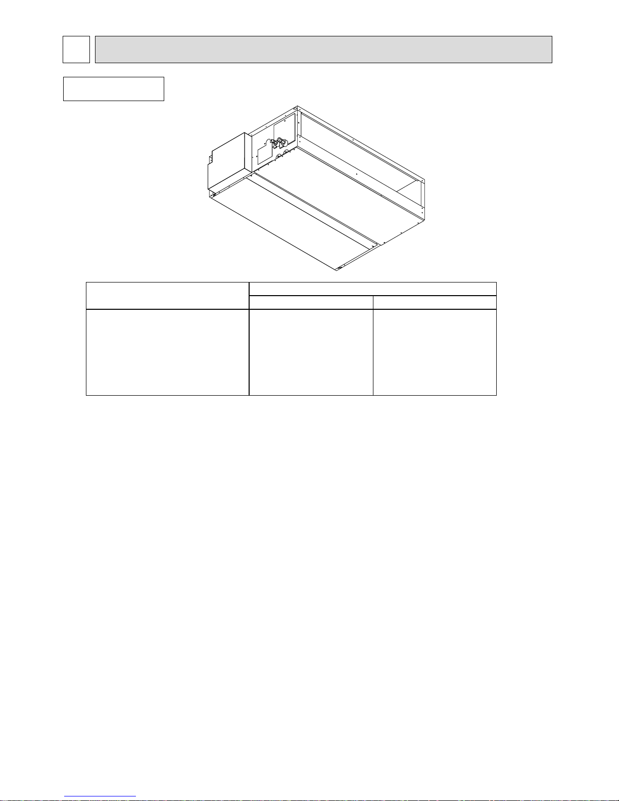
Indoor unit
3
●
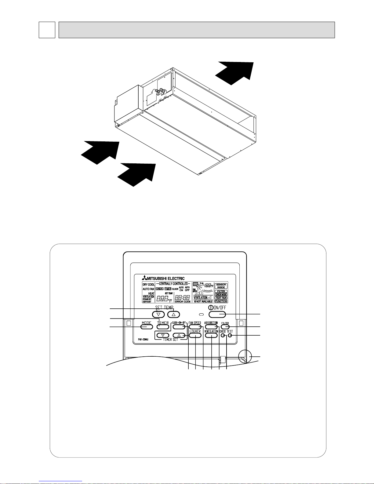
● ● Remote
Indoor (Main) Unit
controller
● Operation buttons
[PAR-20MAA]
Once the controls are set, the same operation mode can
be repeated by simply pressing the ON/OFF button.
1 [Room temperature adjustment] Button
2 [Timer/continuous] Button
3 [Selecting operation] Button
4 [Time selection] Button
[Time-setting] Button
5 [Louver] Button
6 [Fan speed adjustment] Button
7 [Up/down airflow direction] Button
8 [Ventilation] Button
9 [Checking/built-in] Button
0 [Test run] Button
A [Filter] Button
B [ON/OFF] Button
C Position of built-in room temperature
• Never expose the remote controller to direct sunlight. Doing so can result in the erroneous
measurement of room temperature.
• Never place any obstacle around the lower right-hand section of the remote controller. Doing so can
result in the erroneous measurement of room temperature.
1
2
3
456 8 79
0
C
A
B
PART NAMES AND FUNCTIONS2
Air outlet
Air inlet
4
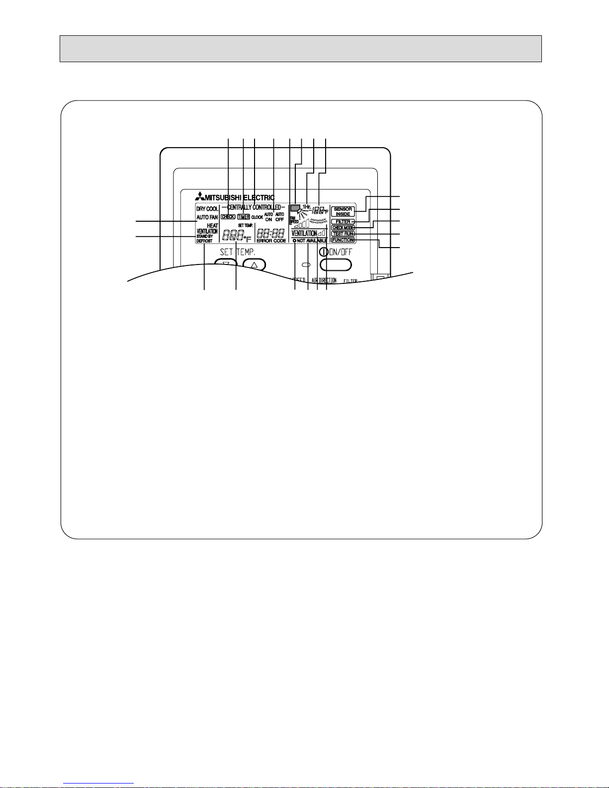
● Display
ABCD
E
F
H
IKLJ
M
P
N
O
R
SQTU
G
(A) Current time/Timer
(B) Centralized control
(C) Timer ON
(D) Abnormality occurs
(E) Operation mode: COOL, DRY, AUTO, FAN, HEAT
(F) Preparing for Heating mode
(G) Defrost mode
(H) Set temperature
(I) Power ON
(J) Louver
(K) Not available function
(L) Ventilation
(M) Function setting mode
(N) Test run mode
(O) Error check mode
(P) Filter sign
(Q) Set effective for 1 hr.
(R) Sensor position
(S) Room temperature
(T) Airflow
(U) Fan speed
5
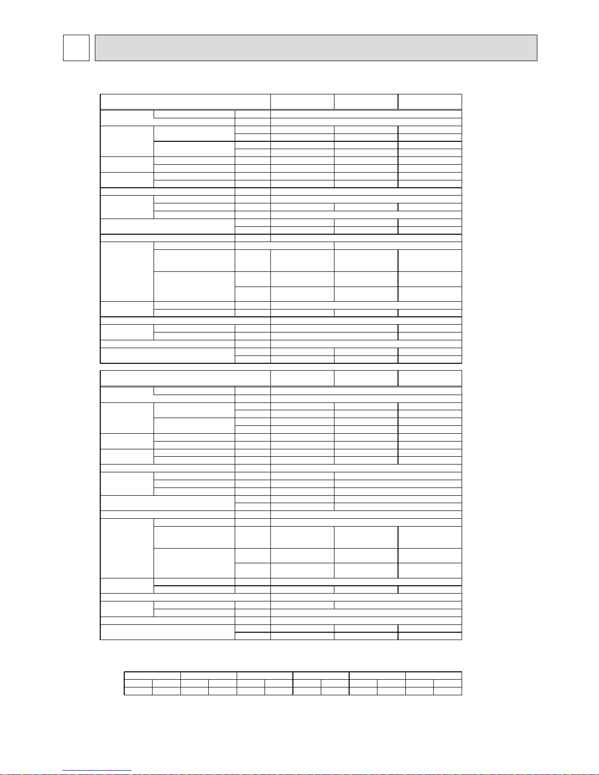
3-1. Specification
Voltage ~V
Frequency Hz
Capacity Cooling kW
*1 BTU
Heating kW
BTU
Power input
Cooling
kW
Heating
kW
Current
Cooling A
(208-230V)
Heating A
Dimensions Height
mm (in)
Width
mm (in)
Depth
mm (in)
Net weight
kg
Ib
Heat exchanger
Type
Airflow rate
(Low-Middle2-Middle1 High)
208V
230V
Type
Output kW
Gas(Flare)
mm (in)
Liquid(Flare)
mm (in)
mm (in)
208V
230V
Noise level (Low-Middle2-Mddle1-High) *3
(208-230V) dB(A)
Filter
Refrigerant
pipe dimension
Refrigerant
pipe dimension
Motor
Drain pipe dimension
External static pressure *2
(208-230V) Pa [in.WG]
FAN
Power sourse
Extwenal finish(Munsel No.)
Power sourse
Extwenal finish(Munsel No.)
FAN
External static pressure *2
(208-230V) Pa [in.WG]
Motor
Filter
Drain pipe dimension
Noise level (Low-Middle2-Mddle1-High) *3
Notes:*1
Cooling/Heating capacity indicates the maximum value at operation under the following condition.
Cooling : Indoor 26.7˚C[80˚F]DB/19.4˚C[67˚F]WB outdoor 35˚C[95˚F]DB
Heating : Indoor 21.1˚C[70˚F]DB outdoor 8.3˚C[47˚F]DB/6.1˚C[43˚F]WB
*2 As the factory setting is below.
Operation temperature
Cooling mode:15˚C[59˚F]WB-24˚C[75˚F]WB
Heating mode:15˚C[59˚F]DB-27˚C[80˚F]DB
*3 The operation noise is the data that was obtained in an anechoic room.
(208-230V) dB(A)
4.6 6.9
15700 23600
5.5 7.4
18700 25400
0.15 0.17
0.15 0.17
0.77-0.85 0.87-0.96
0.77-0.85 0.87-0.96
960(37-13/16) 1160(45-11/16)
32 39
71 86
10-11-12.5-14
[353-388-441-494]
12.5-14.0-16.0-18.0
[441-494-565-635]
30/50/80
[0.120/0.200/0.320]
30/50/80
[0.120/0.200/0.320]
40/60/100
[0.160/0.240/0.401]
40/60/100
[0.160/0.240/0.401]
0.095
ø 15.88(5/8)
ø 9.52(3/8)
32-34-35-37 28-32-34-37
34-36-37-39 30-34-36-39
11.9 13.6
40500 46500
13.2 15.0
45000 51000
0.29 0.39
0.29 0.39
1.48-1.64 1.99-2.21
1.48-1.64 1.99-2.21
19.5-28.0
[688-988]
24.0-34.0
[847-1200]
50-100-130
[0.200/0.401/0.521]
50-100-130
[0.200/0.401/0.521]
60-115-150
[0.240/0.461/0.601]
60-115-150
[0.240/0.461/0.601]
0.140 0.190
36-42 40-45
37-44 42-46
32(1-1/4)
~ 208-230V
Galvanizing
Sirocco fan X 2
735(28-15/16)
PDFY-40NMU-A PDFY-48NMU-A
295(11-5/8)
60Hz
PDFY-16NMU-A PDFY-24NMU-A
335(13-7/32)
1510(59-15/32)
775(30-17/32)
115
~ 208-230V
60Hz
Galvanizing
Sirocco fan X 2
32(1-1/4)
ø 9.52(3/8)
52(2)
ø 19.05(3/4)
2.8
9500
3.2
10800
0.12
0.12
0.61-0.68
0.61-0.68
710(27-31/32)
25.5
57
Sirocco fan X 1
6-6.5-7.5-8.5
[211-229-264-300]
30/50/80
[0.120/0.200/0.320]
40/60/100
[0.160/0.240/0.401]
26-28-31-34
28-30-33-36
9.1
31000
10.0
34000
0.21
0.21
1.07-1.19
1.07-1.19
295(11-5/8)
1160(45-11/16)
735(28-15/16)
39
86
14.0-16.5-18.5-21.0
[494-582-653-741]
30-50-100
[0.120/0.200/0.401]
40-60-115
[0.160/0.240/0.461]
0.095
ø 15.88(5/8)
32-35-38-40
34-37-40-42
Standard filter
ø 12.7(1/2)
ø 6.35(1/4)
Single phase induction motor
0.0850.075
Cross fin(Alminium plate fin and copper tube)
PDFY-32NMU-A
PDFY-10NMU-A
Single phase induction motor
Cross fin(Alminium plate fin and copper tube)
Standard filter
PDFY-10NMU-A
208V
50Pa
230V
60Pa
PDFY-16NMU-A
208V
80Pa
230V
100Pa
PDFY-24NMU-A
208V
80Pa
230V
100Pa
PDFY-32NMU-A
208V
50Pa
230V
60Pa
PDFY-40NMU-A
208V
50Pa
230V
60Pa
PDFY-48NMU-A
208V
50Pa
230V
60Pa
SPECIFICATION3
6
LEV
C1 3.0µF X 440V 5.0µF X 440V
5.0µF
X 440V
8.0µF
X 440V
6.0µF X 440V
MF1
PDFY-
10NMU-A
PDFY-
32NMU-A
PDFY-
40NMU-A
PDFY-
48NMU-A
PDFY-
24NMU-A
PDFY-
16NMU-A
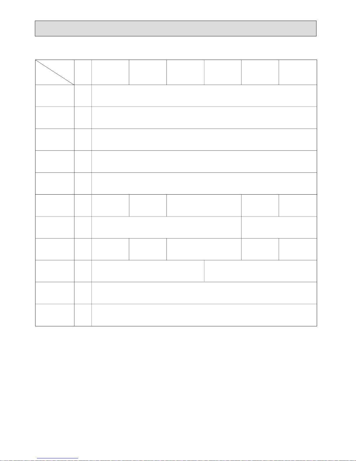
3-2. Electrical parts specifications
Model
Parts
name
Tranrsformer T (Primary) 240V 60Hz (Secondary) (23.5V 0.9A)
TH21 Resistance 0˚C/15kΩ,10˚C/9.6kΩ,20˚C/6.3kΩ,25˚C/5.4kΩ,30˚C/4.3kΩ,40˚C/3.0kΩ
Resistance 0˚C/15kΩ,10˚C/9.6kΩ,20˚C/6.3kΩ,25˚C/5.4kΩ,30˚C/4.3kΩ,40˚C/3.0kΩ
Resistance 0˚C/15kΩ,10˚C/9.6kΩ,20˚C/6.3kΩ,25˚C/5.4kΩ,30˚C/4.3kΩ,40˚C/3.0kΩ
TH22
Gas pipe
thermistor
FUSE 250V 6.3A
TB2 (L1,L2,G) 330V 30A
TB5
TB15
(1,2),(M1,M2,S) 330V 30A
Fuse
(Indoor con-
troller board)
Power supply
terminal bed
Transmission
terminal bed
OFF 130˚C±5˚C
ON 90˚C±20˚C
OFF 150˚C±5˚C
ON 96˚C±15˚C
Room
temperature
thermistor
Fan motor
(with Inner-
thermostat)
4-pole
Output 75W
D104P75MW
4-pole
Output 85W
D104P85MW
4-pole Output 95W
D104P95MW
4-pole
Output 140W
NC-100VM1
4-pole
Output 190W
NC-125VM1
Symbol
DC12V Stepping motor drive port dimension
3.2Ω (0~2000pulse) EDM-402MD
DC12V Stepping motor drive port dimension
5.2Ω (0~2000pulse) EDM-804MD
TH23
Innerthermostat
(Fan motor)
Liquid pipe
thermistor
Fan motor
capacitor
Linear
expansion valve
 Loading...