

Mitsubishi Electric PAC-AH125, PAC-AH140, PAC-AH250, PAC-AH500M-J, PAC-AH125M-J Installation Manual
...
GB
Air Handling Unit Controller
PAC-AH125, 140, 250, 500M-J
FOR INSTALLER
INSTALLATION MANUAL
For safe and correct use, please read this installation manual thoroughly before installing the controller.
2
2
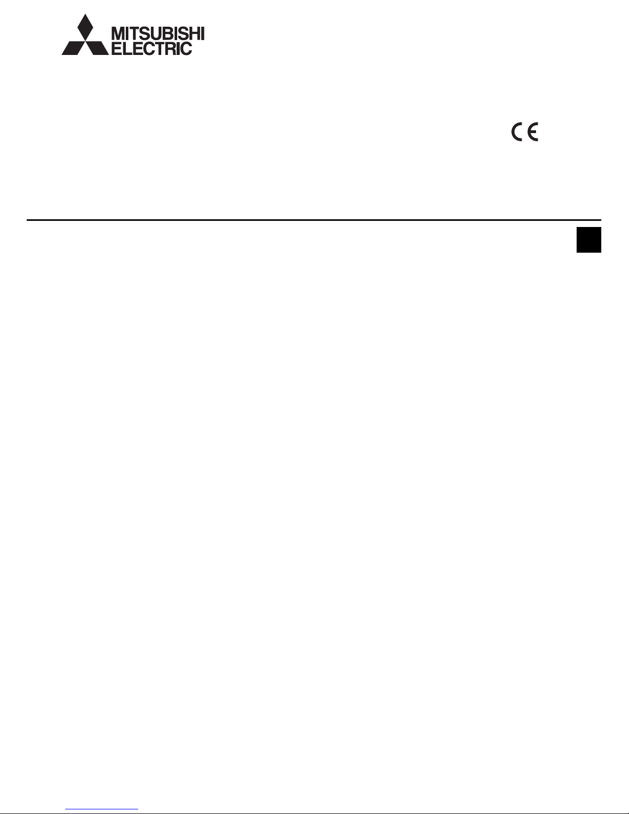
[Fig. 2.0.1]
1 Controller
2 LEV-kit
3 Thermistor
4 Clip
5 Insulation
6 Tie band
7 Installation manual
8 Tube
3
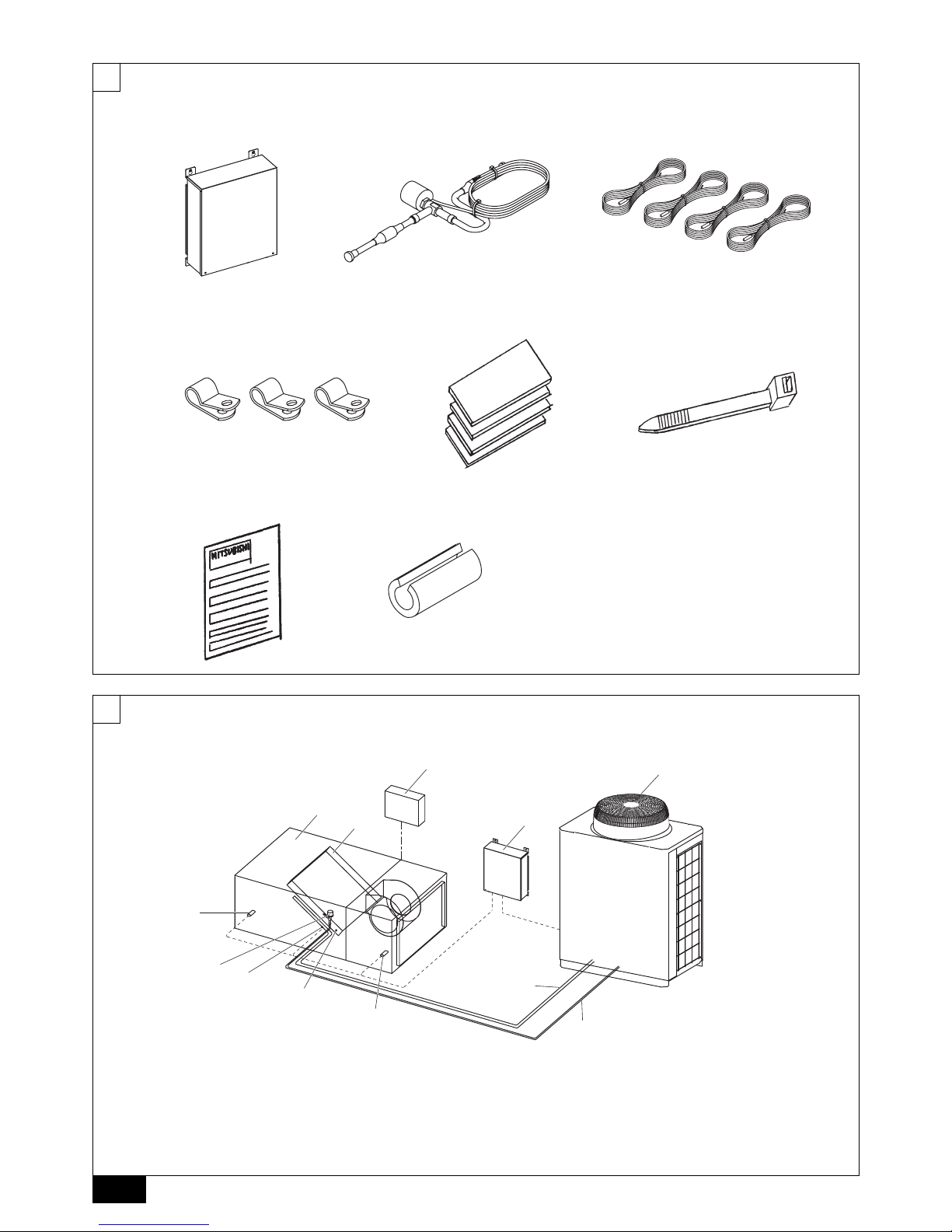
[Fig. 3.0.1]
A Air handling unit controller
(PAC-AH
·
M-J)
B Air handling unit (field supply)
C Controller (field supply)
D Outdoor unit
E Heat exchanger (field supply)
F Gas pipe
G Liquid pipe
H LEV-kit
I Thermistor (gas pipe)
J Thermistor (liquid pipe)
K Thermistor (suction air)
L Thermistor (discharge air)
12 3
4 56
78
B
L
H
I
J
K
G
F
A
C
D
E
3
4
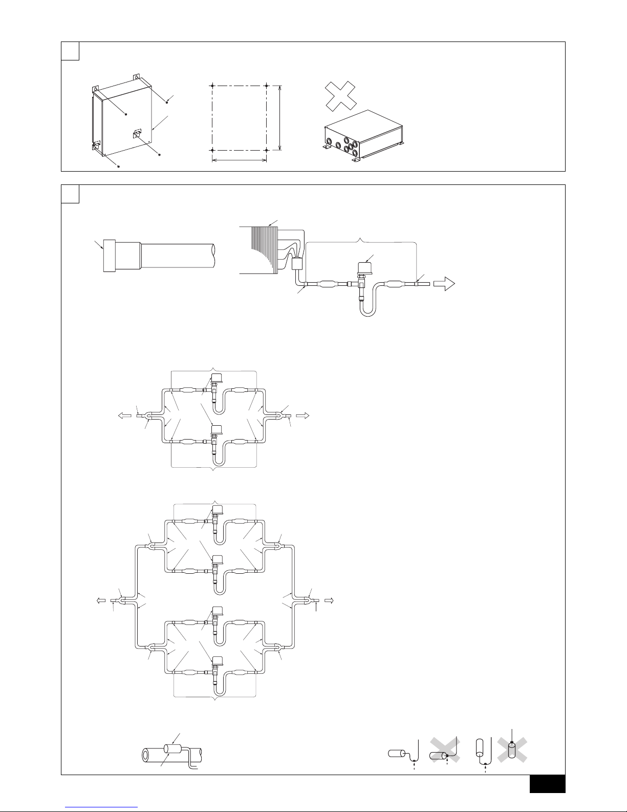
[Fig. 4.2.1]
A Controller
B Screw (field supply)
6
[Fig. 6.2.1]
A Remove the cap
[Fig. 6.2.2]
[Fig. 6.2.3]
A Heat exchanger (field supply)
B LEV-kit
C Brazing
D Linear expansion valve
E Outdoor unit
F Refrigerant pipe size ø9.52 (field supply)
G Distributor (field supply)
H Refrigerant pipe size ø9.52 (field supply)
[Fig. 6.2.4]
A Heat exchanger (field supply)
B LEV-kit
C Brazing
D Linear expansion valve
E Outdoor unit
F Refrigerant pipe size ø9.52 (field supply)
G Distributor (field supply)
H Refrigerant pipe size ø9.52 (field supply)
I Refrigerant pipe size
P400: ø12.7 (field supply)
P500: ø15.88 (field supply)
[Fig. 6.3.0.1] [Fig. 6.3.0.2]
B
A
400
274
A
B
A
D
C
C
E
A Heat exchanger (field supply)
B LEV-kit
C Brazing
D Linear expansion valve
E Outdoor unit
Type 125 - 140
G
G
H
H
C
F
C
F
D
E
A
B
B
Type 250
G
I
H
A
G
G
F
C
D
C
F
C
F
F
C
D
H
G
I
G
G
E
B
B
Type 500
A
B
A Most sensitive point of the thermistor
B Maximize the contact
4
6
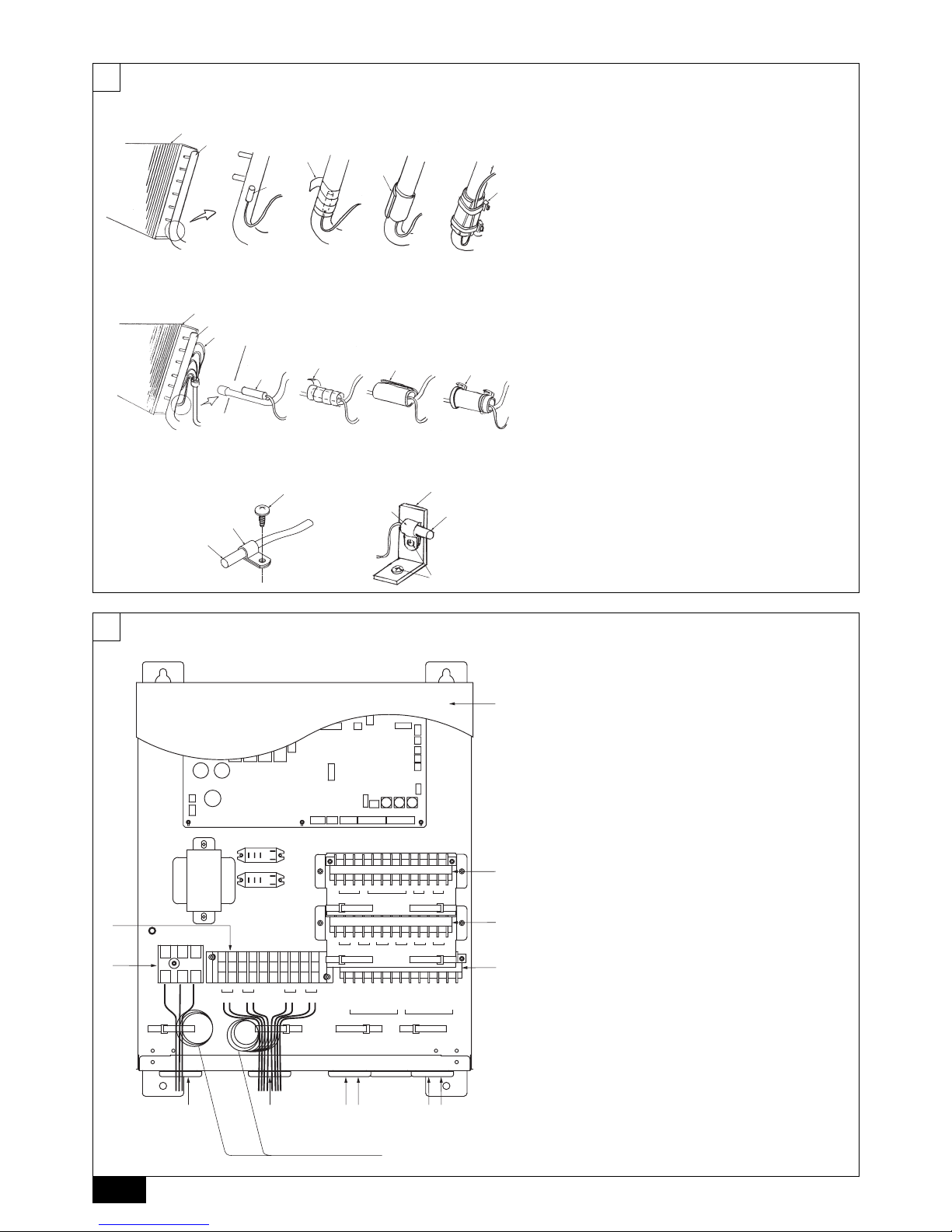
[Fig. 6.3.1]
A Heat exchanger (field supply)
B Gas pipe
C Thermistor (gas pipe)
D Aluminum tape (field supply)
E Insulation
F Tie band
[Fig. 6.3.2]
A Heat exchanger (field supply)
B Gas pipe
C Thermistor (liquid pipe)
D Aluminum tape (field supply)
E Insulation
F Tie band
G Capillary tube
[Fig. 6.3.3]
A Thermistor (suction/disch arge air)
B Clip
C Screw (field supply)
D Plate (field supply)
7
[Fig. 7.0.1]
A Cover
B Terminal block TB2
C Terminal block TB4
D Terminal block TBZ
E Terminal block TBX
F Terminal block TBY
G Power supply (220 - 240 V)/Earth
H Defrost signal
I Fan signal
J Operation signal
K Error signal (output)
L LEV-kit
M LEV-kit
N Distant signal (ON/OFF)
O Error signal (input)
P Thermistor (suction air)
Q Thermistor (gas pipe)
R Thermistor (liquid pipe)
S Thermistor (discharge air)
T To outdoor unit
U Contact signal
V To remote controller
W Analog signal
X Distant signal
Y Thermistor
Z Transmission
A
B
D
E
C
F
A
B
G
D
E
C
F
A
C
C
D
B
B
A
A
F
TUVW
NOPQR
LM
S
E
MZ
B
C
D
LYXG
G
W
H
I
T
E
G
R
E
E
N
B
L
A
C
K
R
E
D
B
R
O
W
N
Y
E
L
L
O
W
A1 A2
M1
CN2M
CN3T
M2
SW4 SW7 SW2 SW3 SW1
CN32
CN22
CN29
CN92
CN21
CN20
CN31
CN51
S
C1 C2 C4 C5 1 2 B1 B2C3
A11 A12 T31 T32 T21 T22 T11 T12 T1 T2
W
H
I
T
E
G
R
E
E
N
B
L
A
C
K
R
E
D
B
R
O
W
N
Y
E
L
L
O
W
H
D31 D32ID24 D23JD1 D2KD11 D12
Wind the wire around the
cable strap once to prevent
loose wires.
5
7
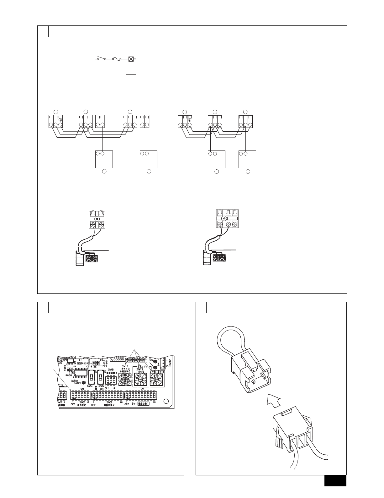
[Fig. 7.1.1]
A Switch 16 A
B Overcurrent protection 16 A
C Indoor unit
D Pull box
[Fig. 7.2.1] [Fig. 7.2.2]
A Terminal block for AHU controller/
indoor transmission cable
B Terminal block for outdoor transmis-
sion cable
C Remote controller
[Fig. 7.2.3] [Fig. 7.2.4]
A Non-polarized
B Remote Controller
89
[Fig. 8.1.1]
A Address switch
B SW2
[Fig. 9.0.1]
AB
D
C
TBY TBY TBY TBY
SM1M2 SM1M2
TB3
M1M2 21 21
AA
B
CC
TBY TBY
SM1M2 SM1M2
TB3
M1M2
AA
B
CC
DC10~13 V
AB
12
A
B
2
1
DC24~30 V
(A, B)
12
A
B
M2
M1
S
A
B
 Loading...