

Mitsubishi Electric PAC-AH63, PAC-AH140, PAC-AH250M-G Installation Manual
Air Handling Unit Controller
PAC-AH63, 125, 140, 250M-G
INSTALLATION MANUAL
For safe and correct use, please read this installation manual thoroughly before installing the controller.
GB
FOR INSTALLER
2
A
L
B
D
E
C
F
H
J
K
I
G
2
[Fig. 2.0.1]
3
[Fig. 3.0.1]
12 3
456
7
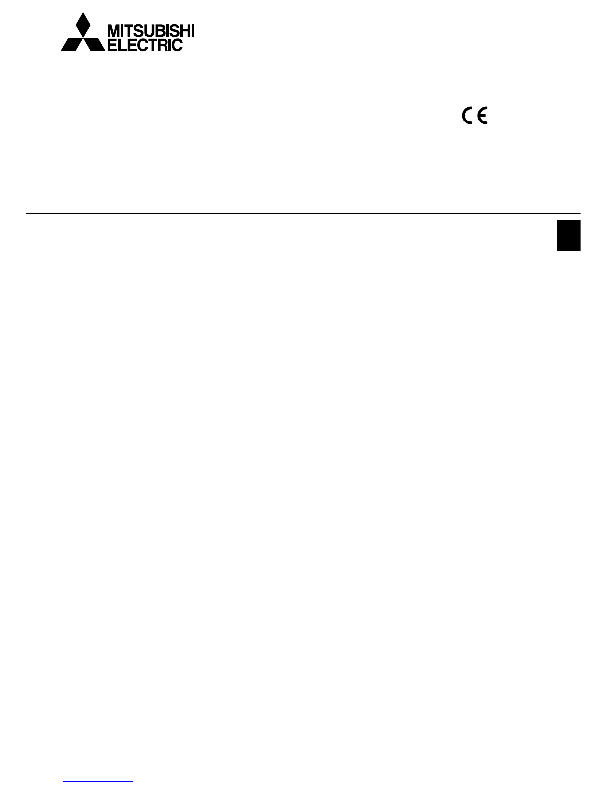
1 Controller
2 LEV-kit
3 Thermistor
4 Clip
5 Insulation
6 Tie band
7 Installation manual
8 Tube
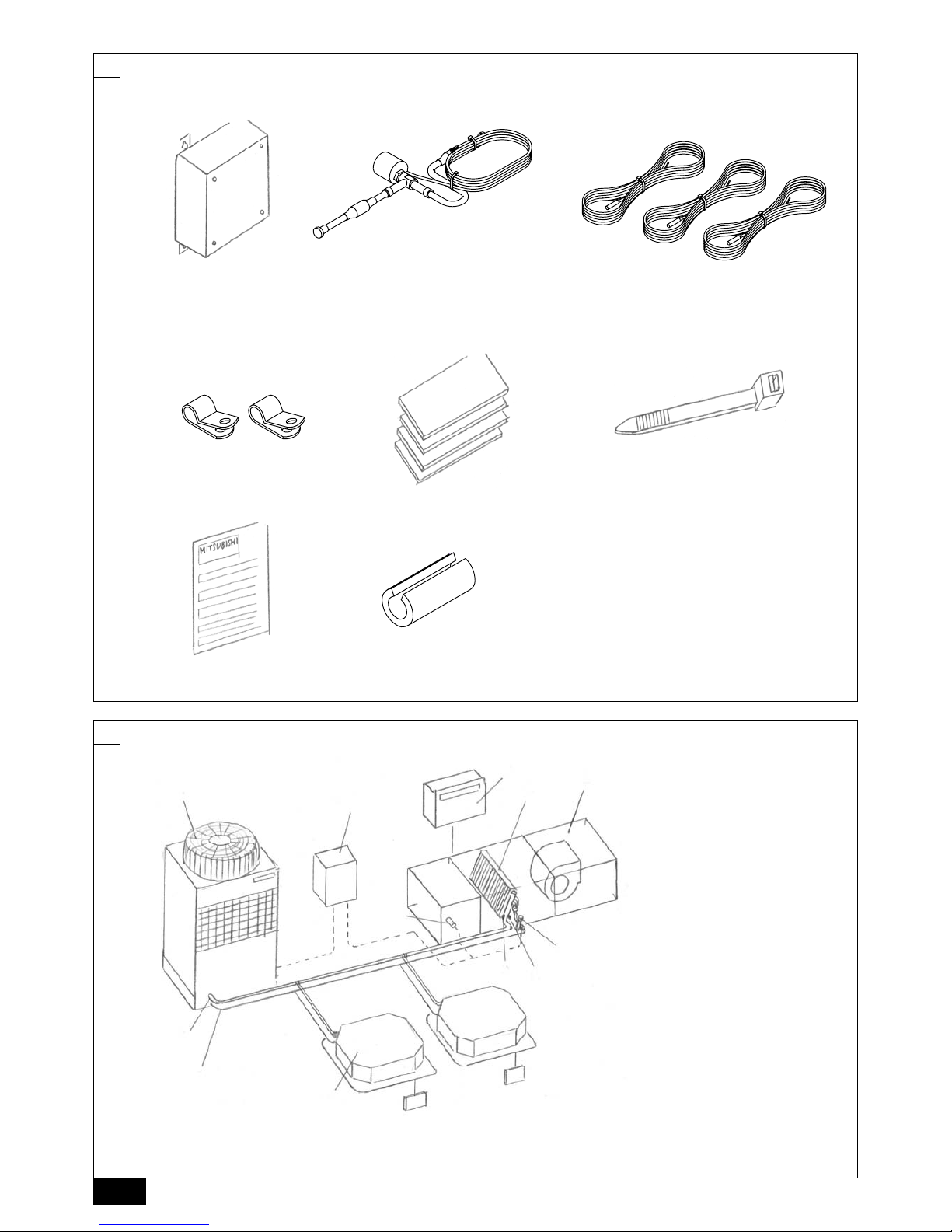
A Air handling unit controller (PAC-AH · M-G)
B Air handling unit (field supply)
C Controller (field supply)
D Outdoor unit
E Indoor unit (City Multi)
F Evaporator (field supply)
G Gas pipe
H Liquid pipe
I LEV-kit
J Thermistor (gas pipe)
K Thermistor (liquid pipe)
L Thermistor (inlet air)
8
3
A
B
D
C
C
E
G
E
B
B
G
A
C
C
H
FF
D
H
4
[Fig. 4.2.1]
6
[Fig. 6.2.2]
[Fig. 6.2.3]
B
A
410
260
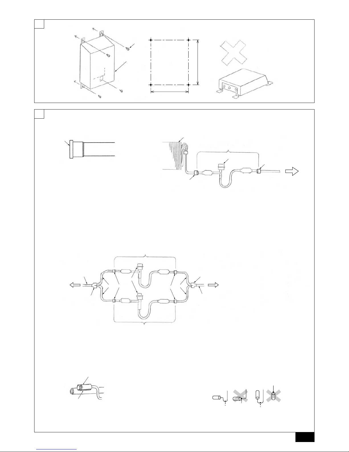
A Controller
B Screw (field supply)
A Evaporator (field supply)
B LEV-kit
C Brazing
D Linear expansion valve
E Outdoor unit
F Refrigerant pipe size ø9.52 (field supply)
G Distributor (field supply)
H Refrigerant pipe size ø9.52 (field supply)
Type 63 - 140
Type 250
A Evaporator (field supply)
B LEV-kit
C Brazing
D Linear expansion valve
E Outdoor unit
[Fig. 6.2.1]
A
A Remove the cap
[Fig. 6.3.0.1]
A
B
A Most sensitive point of the
thermistor
B Maximize the contact
[Fig. 6.3.0.2]
4
A
B
G
D
E
C
F
A
C
C
D
B
B
A
F
J
K
L
P
G
G
P
O
Q
J
R
H
I
R
D
C
O
MN
S
E
A
B
TB2
TB15
TB4
TBX
T21 T22 T11 T1 T2T12
white
yellow
green
black
red
brown
TB5
Q
7
[Fig. 7.0.1]
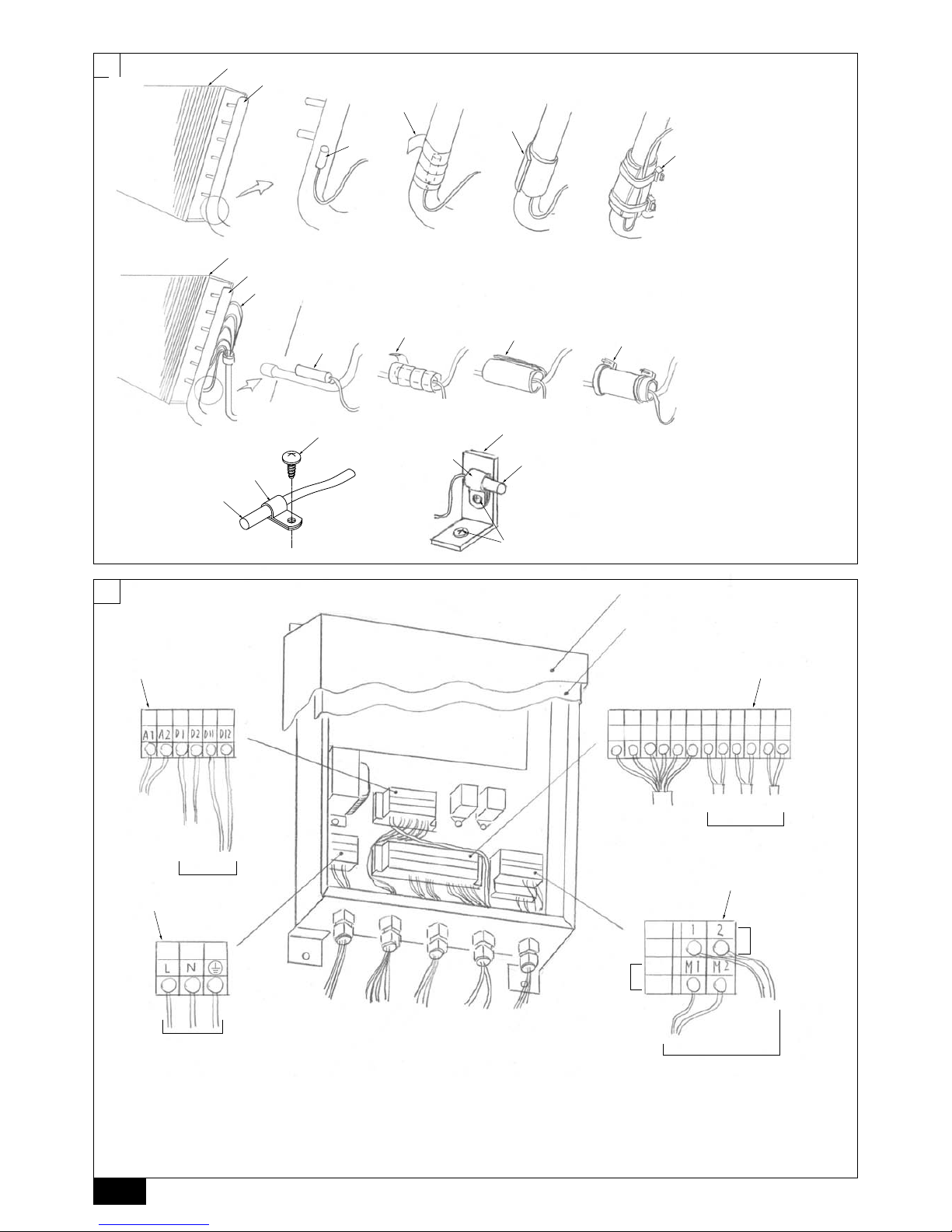
A Outer cover
B Inner cover
C Terminal block TB2
D Terminal block TB5 TB15
E Terminal block TBX
F Terminal block TB4
G Power supply (220 - 240 V)/Ear th
H To outdoor unit
I To remote controller
J Distant signal (ON/OFF)
K Operation signal
L Error signal
M Thermistor (gas pipe)
N Thermistor (liquid pipe)
O LEV-kit
P Distant signal
Q Thermistor
R Transmission
S Thermistor (inlet air)
A Evaporator (field supply)
B Gas pipe
C Thermistor (liquid pipe)
D Aluminum tape (field supply)
E Insulation
F Tie band
G Capillary tube
6
[Fig. 6.3.3]
A Thermistor (inlet air)
B Clip
C Screw (field supply)
D Plate (field supply)
A
B
D
E
C
F
[Fig. 6.3.1]
A Evaporator (field supply)
B Gas pipe
C Thermistor (gas pipe)
D Aluminum tape (field supply)
E Insulation
F Tie band
[Fig. 6.3.2]
5
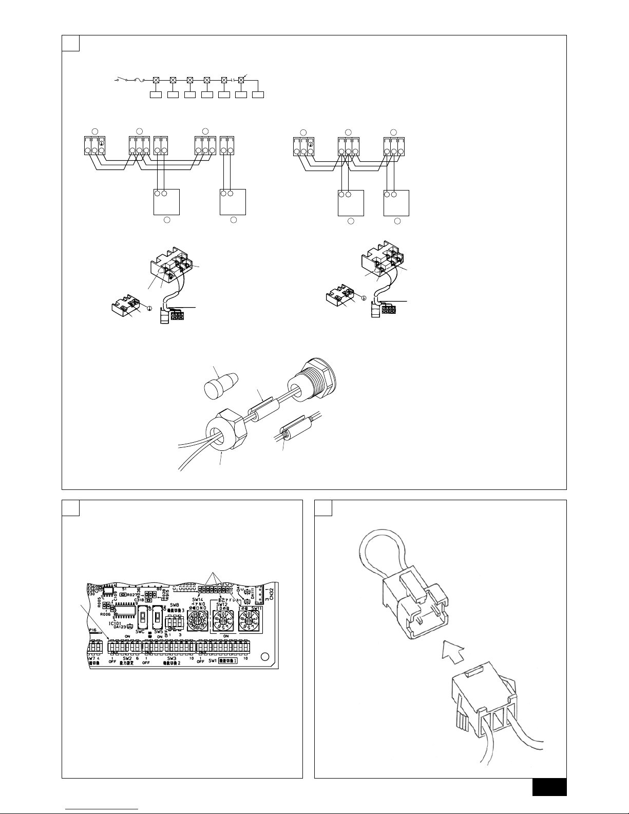
[Fig. 7.1.1]
[Fig. 7.2.1] [Fig. 7.2.2]
[Fig. 7.2.3] [Fig. 7.2.4]
A Terminal block for AHU controller/
indoor transmission cable
B Terminal block for outdoor trans-
mission cable
C Remote controller
M2
DC24~30V
M1
(A, B)
12
D
A
C
L
N
DC10~13V
AB
12
L
N
1
2
A
C
B
A Non-polarized
B Upper level (TB15)
C Remote Controller
D Lower level (TB5)
AB
DE
CCCCCCC
A Switch 16 A B Overcurrent protection 16 A
C Indoor unit D Total operating current be less than 16 A
E Pull box
TB5 TB5
SM1M2 SM1M2
TB3
M1M2
AA
B
CC
TB5 TB15 TB5 TB15
SM1M2 SM1M2
TB3
M1M2 21 21
AA
B
CC
7
9
[Fig. 9.0.1]
8
[Fig. 8.1.1]
A Address switch
B SW2
A
B
[Fig. 7.2.5]
B
C
A
D
A Bunch of wires
B Plug
C Tube
D Insulation tape
 Loading...