

Page 1
1. Outline
This fan controller apply to following units.
These units can be operated on cooling mode at the low ambient temperature with this optional FAN CONTROLLER.
Please read carefully this manual and install following this.
Model name Q'TY
1 set 2 set
3. Parts
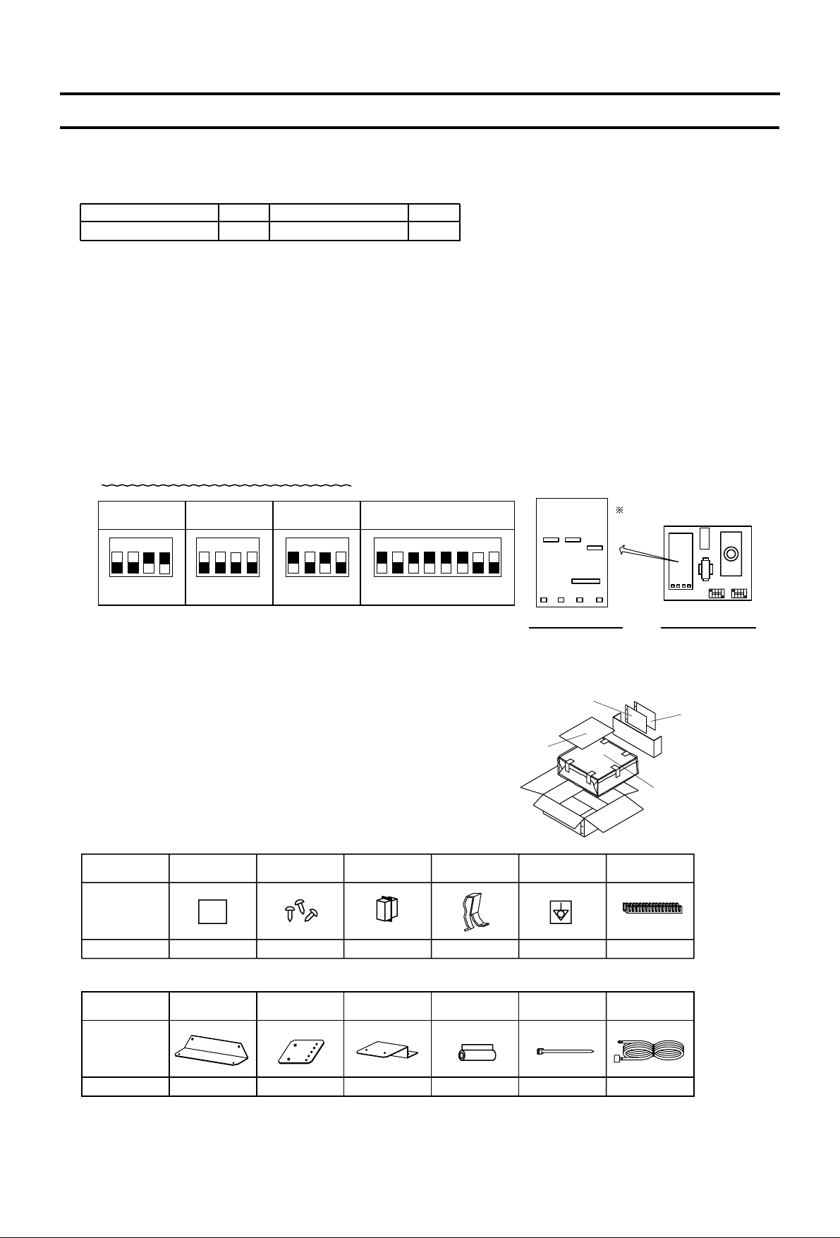
There are the following parts in this box, and confirm whether there are all attached.
There are two kinds of wiring sticker in this box.
Please select the pertinent one by model name.
2. Caution
Accessory assy 1
Name
Shape
Amount 2 12 1 1 1
1
2
Earth stickerWiring sticker Screw Connector cap Spring
Connector assy
Grommet
Accessory assy 2
Name
Shape
Amount 1 1 3 3 15
Attachment Attachment Attachment Pipe cover Band
(3,4 ON) (All OFF) (1,3 ON) (1,3,4,5,6 ON)
SW0 SW1 SW2 SW3
ON ON ONONON
Model name Q'TY
PRHG-15,20PRHG-8,10
34213421342134267851
Accessory assy 2
Accessory assy 1
Installation manual
(This manual)
Fan controller
SW3
SW1
SW0
SW2
Fan controller insideControl circuit board
Only SW3 direction is different.
1. Fan controller changes the outdoor fan speed.
Strong wind is injurious to fan speed controller.
Please install the windproof when unit is influenced by strong wind such as install it on the place there is no building in
surrounding or the rooftop
2. As the case may be the operation with FAN CONTROLLER generate an electromagnetic sound from fan motor.
Please consider the soundproofing wall equipment etc. when using the fan controller in the place where the noise
becomes a problem.
There is no worry which interferes to the unit though an electromagnetic sound might be generated from fan motor.
3. When shipping the fan controller, the dip switch on the control circuit board is set as follows.
Do not change factory set of all dip switches.
LOW AMBIENT COOLING PARTS; OPTION PAC-205FC (Fan controller)
-51-
Page 2
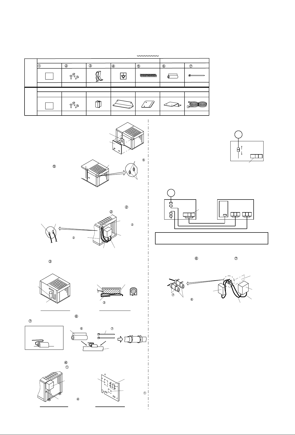
4.1. PRHG-8,10
4.1.1. Install
Insert the thermistorThermistor position
1. The service panel and control box
cover are removed.
2. Penetrate the knockout holes at
the top panel.
The grommet (2 pieces)
install to the hole for wiring
in the top panel.
4. Confirm the thermistor holder position.
The spring insert in the thermistor holder.
The thermistor (black wiring) which is connected to the fan
controller is put in the holder.
3.
6. The earth sticker and wiring sticker are put on an following place.
1. The earth sticker is put on the pillar.
2. The wiring sticker is put on the service panel cover (inside).
Put a wiring stickerPut a earth sticker
5. Please use the pipe cover (1 piece) and fix with the band
(2 pieces).
4.1.2. Wiring
3. After connect wiring, to prevent wiring being damaged with
the fin, the pipe cover (2 pieces) and band (4 pieces)
are used.
In that time, never bundle the thermistor wiring with other
wiring.
4. After wiring ends, the wiring is bundled with a remaining band.
Never bundle the thermistor and other wiring together.
5. Ensure there is not wiring mistake found, then only install the
controller box cover and service panel.
Fan
controller
Earth sticker
Unit wiring
sticker
Fan
controller
1. Disconnect connector C11 - C11.
The connector C11 removes to the motor
side and the control box side.
2. When the fan controller is installed, the connector is
connected in the control box.
The wiring from CN04 connect to the terminal block (F/C, N)
in the control box.
Please be careful, do not damage wires by the sheet metal edges
or the fin, etc.
MF2
Control box
C11
C11
Terminal block
Pipe cover Band
Pipe
Other wiringThermistor wiring
only
Compressor
Service panel
Control box
cover
Thermistor wiring
only
Other wiring
Fan controller
wiring sticker
Instruction
assy
Fan
controller
Thermistor
wiring only
Other wiring
Top panel
Control
box
Band
Pipe cover
Thermistor
wiring only
Other wiring
Install to
the top panel.
(Screw 2 pieces)
Install to the holder.
(Screw 1 piece)
Thermistor
holder position
CN04
UVW L1 L2 L3
MF2
Terminal block
Control box
Fan controller
C11
C11
Top panel
Grommet
Wiring hole
F/C N
F/C N
Thermistor Thermistor holder
Spring
The thermistor wiring is
bundled as follows before
the pipe cover is installed.
Please use the following parts during installation of fan controller.
There are two kinds of wiring sticker, please use writing as “W881927”.
Wiring from the fan controller is passed through the hole of
procedure 2.
The thermistor and other wiring should use separate wiring hole.
The fan controller install to the top panel with the screw (2
pieces) and install to the holder with the screw (1 piece).
Accessory assy 1
Wiring sticker Earth stickerScrew
Spring
Grommet
Accessory assy 2Accessory assy 1
Use
Not
use
Attachment
ONLY PU(H)-7,8,10
Accessory assy 2
Pipe cover Band
1
Attachment
1
Attachment
311
1
3
Screw Connector
9
113152
Wiring sticker
1
Connector assy
4. Instllation
-52-
Page 3
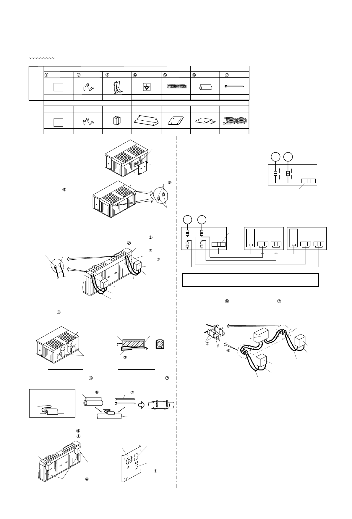
4.2. PRHG-15,20
4.2.1. Install
Insert the thermistorThermistor position
1. The service panel and control box
cover are removed.
2. Penetrate the knockout holes at
the top panel.
The grommet (2x2 pieces)
install to the hole for wiring
in the top panel.
4.
3.
6. The earth sticker and wiring sticker are put on an following place.
1. The earth sticker (2x1 pieces) is put on the pillar.
2. The wiring sticker (1 piece) is put on the service panel cover
(inside).
1.
Put a wiring stickerPut a earth sticker
4.2.2. Wiring
3.
4. After wiring ends, the wiring is bundled with a remaining band.
Never bundle the thermistor and other wiring together.
5.
2.
Earth sticker
Please be careful, do not damage wires by the sheet metal edges
or the fin, etc.
Pipe cover Band
Pipe
Thermistor holder
position
Compressor
Thermistor wiring
only
Other wiring
Band
Pipe cover
Thermistor
wiring only
Other wiring
Service panel
Control box
cover
Fan controller
wiring sticker
Instruction assy
Unit wiring sticker
Fan controller
Install to the pillar.
(Screw 1 piece)
Install to the top panel.
(Screw 2 pieces)
Other wiring
Thermistor wiring only
Other wiring
Thermistor wiring only
Fan controller
Fan controller
Control box
MF2 MF3
Terminal block
C11
C11
C21
C21
Fan
controller
Thermistor wiring only
Other wiring
Control box
Top panel
CN04
UVW L1 L2 L3
MF2 MF3
Terminal
block
CN04
UVW L1 L2 L3
Control box
Fan controller Fan controller
C11
C11
C21
C21
Fan controller
(As well as the another side.)
6. Please use the pipe cover (2x1 pieces) and fix with the band
(2x2 pieces).
Accessory assy 1
Wiring sticker Earth stickerScrew
Spring
Grommet
Accessory assy 2Accessory assy 1
Use
Not
use
Attachment
ONLY PU(H)-7,8,10
Accessory assy 2
Pipe cover Band
1
Attachment
1
Attachment
31
1
13
Screw Connector
9
1
13152
Wiring sticker
1
Connector assy
Thermistor Thermistor holder
Spring
F/C N
F/C N
Grommet
Wiring hole
The thermistor wiring is
bundled as follows before
the pipe cover is installed.
Please use the following parts during installation of fan controller. There are two kinds of wiring sticker, please use writing as
“W881927”.
The fan controller is necessary for these models by two sets. (The following accessory parts show the fan controller one set.)
Fan
controller
Thermistor wiring only
Other wiring
Top panel
Wiring from the fan controller is passed through the hole of
procedure 2.
The thermistor and other wiring should use separate wiring hole.
The fan controller install to the top panel with the screw (2x2
pieces) and install to the pillar with the screw (2x1 pieces).
Confirm the thermistor holder position. (2 places)
The spring (2x1 pieces) insert in the thermistor holder.
The thermistor (black wiring) which is connected to the fan
controller is put in the holder.
Disconnect connector C11 - C11 and
C21 - C21.
The connector C11 and C21 remove
to the motor side and the control box
side.
When the fan controller is installed, the connector is connected
in the control box.
The wiring from CN04 connect to the terminal block (F/C, N) in
the control box.
After connect wiring, to prevent wiring being damaged with the
fin, the pipe cover (2x2 pieces) and band (2x4 pieces) are
used.
In that time, never bundle the thermistor wiring with other
wiring.
Ensure there is not wiring mistake found, then only install the
controller box cover and service panel.
-53-
Page 4

5. Before starting the trial run
Please execute the following confirmations to prevent wrong connection.
If there is wrong connection, it may damage fan controller, but also damage the unit.
Confirmation
Please intercept the power supply without fail, and secure safety when you execute detaching wiring, the connector,
and the measurement machine to the following work.
Step
Step 1
Confirmation matter Check Correspondence
Connected confirmation
Step 1-1 Is fan controller's power supply input wiring position connected correctly as
shown in installed manual?
Step 1-2 Is the phase of the connection of fan controller power supply input (TB IN)
accurate?
Step 1-3 Is the phase of the connection of fan controller output (TB OUT) accurate?
Step 1-4 Is the phase of connection of fan controller output wiring to fan motor accurate?
Step 2
Drive confirmation
Step 2-1 Does the fan rotate in a correct direction, when the unit is driven ?
Step 2-2 The thermistor for the condensing temperature detection is removed to CN01.
Drive to the cooling operation.
(The unit stops abnormally when the cooling operation drive is continued for a
long time occasionally. - High pressure switch off)
Whether LED01 has blinked is confirmed.
When the unit is in operation, the fan controller output voltage measured
in TB OUT, and checked whether the output of about 200V.
There is a problem when it is an output of about 300V.
Step 2-3 The thermistor for the condensing temperature detection is surely connected
with CN01 as before.
Step 2-4
Step 1-5 Is the thermistor for the condensing temperature detection of the attachment
connected with CN01?
Step 1-6 Is the thermistor for the condensing temperature detection accurately installed
in the unit?
Step 1-7 In case of the heat pump model, the wiring for full load input is connected with
CN04?
In case of the heat pump model and the heating drive is possible, the heating
drive is executed and the voltage of CN04 is input AC198V - 264V.
In that case, the fan must be full load drive.
(The output of the power-supply voltage is confirmed in TB OUT. )
When heating cannot be driven, step 1-7, step 1-8 is executed again.
In case of the heat pump model, the wiring for full load input is connected
accurately in control box?
Step 1-8
Troubleshooting 1,2
Troubleshooting 3
Troubleshooting 4
CN04
U
TB OUT
VW L1 L2 L3
CN01
Fan controller layout
Refer to Step 1-2
Refer to Step 1-5
Step 2-2
Step 2-3
Refer to Step 1-7
Step 2-4
U : Red
V : White
W : Black
L1 : Red
L2 : White
L3 : Black
Refer to Step 1-3
TB IN
-54-
Page 5

6. Troubleshooting (PAC-205FC)
State of Machine
Cause Check point
1. The fun does not run.
Content of confirmation
3) The transformer (T01) is defective.
4) The thyristor module (SCRM) is defective.
5) The control printing wiring board is
defective.
6) The fan motor and unit side control box
are defective.
2) Connected mistake
1) The power-supply voltage is abnormal. The value of power-supply voltage is
confirmed. (TB IN)
Fan power supply wiring is connected
with fan controller power supply taking
out part, and confirm operation.
The blinking of LED01 is confirmed.
The resistance is confirmed.
(Between the lines of primary side, and
lines of secondary side.)
The content of P15 is checked. (SCRM) The content of P15 is judgment. (SCRM)
Whether the voltage is input to fan motor is
confirmed.
Whether the fan motor operation is
confirmed.
The fan controller connection is confirmed.
The unit side connection is confirmed.
Is the power-supply voltage 342-457V?
Troubleshooting
Replace the transformer in case of abnormal
resistance.
When the voltage impression and fan motor does
not work, fan motor is defective.
When the voltage is not impressed to the fan, the
unit side control box is defective.
When there is no wrong above-mentioned,
it is assumed fan controller connection state,
if abnormality relapses, the control printing board
is defective and exchange.
Replace SCRM when abnormality is found.
At the time of turning on light. (always)
The CN01 connector is removed, and measures
resistance. When the resistance is 1 kilo-ohm or
less, repair the control printing board due to the
thermistor short-circuit breakdown.
In case of thermistor is correct, the control
printing board is defective and exchange.
At the time of turning off light.
The CN01 connector is removed, and measures
resistance. When the resistance is 25 kilo-ohm or
more, repair the control printing board due to the
thermistor open breakdown.
In case of thermistor is correct, the control
printing board is defective and exchange.
The wiring mistake is corrected.
The power supply wiring is confirmed,
and corrected.
TB OUT - fan motor
Resistance between the lines of primary side
(red and white) about 310 ohm.
Resistance between the lines of secondary
side (CN02 the connector is removed from
the printing wiring board.)
Between 1-3 pin about 0.9 ohm
CN02- thermistor
NF-SCRM-TB OUT
CNU, CNV, CNW-SCRM
(The connection is noted.)
TB IN-NF wiring
TB IN-T01-CN02.
After checking item 1)-4), when the power
supply is turned on, the blinking of LED01 is
confirmed.
Please intercept the power supply without fail, and secure safety when you execute detaching wiring, the connector,
and the measurement machine to the following work.
-55-
Page 6

State of Machine
Cause Check point Content of confirmation
4) The control printing wiring board setting
is defective.
3) Connected mistake
3) Connected mistake
2) Output wiring supply reverse-phase.
1) Power supply reverse-phase.
2) Power supply reverse-phase.
Output wiring reverse-phase.
The phase of fan motor output wiring is
confirmed. (TB OUT)
The phase of fan motor output wiring is
confirmed. (TB OUT)
The phase of input voltage is confirmed.
(TB IN)
The phase of input voltage is confirmed.
(TB IN)
The set of dip switch is confirmed. (SW0-3)
(P2)
It is confirmed that the switch setting is
corresponding to the electric wiring diagram.
The control substrate is matched to setting the
electric wiring diagram.
The fan controller connection is confirmed.
The fan controller connection is confirmed.
The input voltage is confirmed. (CN04)
Is the phase of U, V, W correct?
Is the phase of L1, L2, L3 correct?
Is the phase of U, V, W correct?
Is the phase of L1, L2, L3 correct?
Troubleshooting
The phase of U, V, W is corrected.
The connected phase is confirmed.
The wiring mistake is corrected.
The phase of L1, L2,L3 is corrected.
The phase of U, V, W is corrected.
The phase of L1, L2,L3 is corrected.
NF-SCRM-TB OUT (The connection phase
is noted.)
CNU, CNV, CNW-SCRM
(The connection is noted.)
Is not AC198-264V input in CN04?
TB IN-NF wiring (The connection phase is noted.)
2. The fan rotates
oppositely.
3. The rotation speed
of fans cannot control.
Something wrong
occurs by step2-2 drive
confirmation of installed
confirmation matter.
It becomes high-
pressure abnormal
pressure.
1) During heating drive During heating drive, there is an input in CN04 and
the fan becomes full load drive. Normality
CN04- the wiring for full load input in heating
(CN04 input is AC198-264V in heating.)
There must not be connector connection in
CNX.
(CNX is compulsion full load input.
Full load when short-circuited.)
NF-SCRM-TB OUT (The connection phase is
noted.)
CNU, CNV, CNW-SCRM
(The connection is noted.)
TB IN-NF wiring (The connection phase is
noted.)
TB IN-T01-CN02 (The connection phase is
noted.)
CN02- thermistor
The connected phase is confirmed.
The wiring mistake is corrected.
In cooling, when there is an input in CN04, wiring
of CN04 is mistake connection.
The wiring is corrected.
When there is an input in CN04, the fan is full load..
When there is a connector connection in CNX,
it is removed.
The unit side connection is confirmed.
The connected phase is confirmed.
The wiring mistake is corrected.
TB OUT - fan motor
(The phase (U, V, W) is noted.)
Position of the wiring for full load input
(In heating)
Installation position of thermistor
If the position where the thermistor is installed is
wrong, the rotation speed control of the fan as
condensing temperature is impossible.
5) The thyristor module (SCRM) is defective. The content of P14 is checked. (SCRM) The content of P14 is judgment. (SCRM) SCRM exchange when abnormality is found.
-56-
Page 7

State of Machine
Cause Check point Content of confirmation
1) Connected mistake The fan controller connection is confirmed.
Troubleshooting
6) The control printing wiring board is
defective.
The blinking of LED01 is confirmed. At the time of turning on light (always)
(There is a possibility of the thermistor short-circuit.)
The CN01 connector is removed, and measures
resistance. When the resistance is 1 kilo-ohm or
less, repair the control printing board due to the
thermistor short-circuit breakdown.
In case of thermistor is correct, the control printing
board is defective and exchange.
At the time of turning off light
(There is a possibility of the thermistor open
breakdown.)
The CN01 connector is removed, and measures
resistance. When the resistance is 25 kilo-ohm or
more, repair the control printing board due to the
thermistor open breakdown.
In case of thermistor is correct, the control printing
board is defective and exchange.
After checking item 1)-5), when the power
supply is turned on, the blinking of LED01
is confirmed.
3) The control printing wiring board is
defective.
Item 1) is checked, again.After checking item 1), there is a
possibility of a defective printed circuit
board if a normal drive is not done.
After checking item 1), if there is no problem,
the control printing board is defective and exchange .
4. The f an ne v er
becomes full load
drive. (In heating)
CN04- the wiring for full load input
(CN04 input is AC198-264V in heating.)
NF-SCRM-TB OUT
CNU, CNV, CNW-SCRM
(The connection is noted.)
TB IN-NF wiring
TB IN-T01-CN02
It is confirmed that wiring is correctly connected.
The wiring mistake is corrected.
At the time of blinking
The item 2), 3) are confirmed again, and there is
no connection mistake, the control printing board
is defective and exchange.
The wiring mistake is corrected. The unit side connection is confirmed. Position of the wiring for full load input
(In heating)
2) The thyristor module (SCRM) is defective. The content of P14 is checked. (SCRM) The content of P14 is judgment. (SCRM) Replace SCRM when abnormality is found.
-57-
Page 8

Thyristor module
(SCRM)
<Judgment Method> Measure the resistance between each of the SCRM pins and judge if there is a failure or not by the resulting
values.
<Judgment Values 1> Check between G and K.
Use the smallest resistance range on the tester.
Judgment Value: 1.5 ohm 80 ohm
<Judgment Values 2>
<External View>
<Internal Circuit Diagrams>
Check between AK1 and AK2.
Use the greatest resistance range on the tester.
Judgment Value: 60 kilo-ohm ohm
K
AK1
AK1
AK1 AK1
AK2
AK2
AK2 AK2
GKGKG
GK GK GK
K
K
AK1
AK2
G
G
K
K
AK1
AK2
G
G
G
K
G
K
-58-
 Loading...