

Page 1
Models
PUHY-P72, P96, P120, P144T(Y)JMU-A
PUHY-P168, P192, P216, P240, P264, P288T(Y)SJMU-A
PUHY-P312, P336, P360T(Y)SJMU-A
Page 2
WARNING
CAUTION
WARNING
Safety Precautions
Before installing the unit, thoroughly read the following safety precautions.
Observe these safety precautions for your safety.
This symbol is intended to alert the user to the presence of important instructions that must be followed to avoid
the risk of serious injury or death.
This symbol is intended to alert the user to the presence of important instructions that must be followed to avoid
the risk of serious injury or damage to the unit.
After reading this manual, give it to the user to retain for future reference.
Keep this manual for easy reference. When the unit is moved or repaired, give this manual to those who provide these
services.
When the user changes, make sure that the new user receives this manual.
Ask your dealer or a qualified technician to install the
unit.
Improper installation by the user may result in water leakage, electric shock, smoke, and/or fire.
Properly install the unit on a surface that can withstand the weight of the unit.
Unit installed on an unstable surface may fall and cause injury.
Only use specified cables. Securely connect each cable so that the terminals do not carry the weight of the
cable.
Improperly connected or fixed cables may produce heat
and start a fire.
Take appropriate safety measures against strong
winds and earthquakes to prevent the unit from falling.
If the unit is not installed properly, the unit may fall and
cause serious injury to the person or damage to the unit.
Do not make any modifications or alterations to the
unit. Consult your dealer for repair.
Improper repair may result in water leakage, electric shock,
smoke, and/or fire.
In the event of a refrigerant leak, thoroughly ventilate
the room.
If refrigerant gas leaks and comes in contact with an open
flame, poisonous gases will be produced.
When installing the All-Fresh type units, take it into
consideration that the outside air may be discharged
directly into the room when the thermo is turned off.
Direct exposure to outdoor air may have an adverse effect
on health. It may also result in food spoilage.
Properly install the unit according to the instructions
in the installation manual.
Improper installation may result in water leakage, electric
shock, smoke, and/or fire.
Have all electrical work performed by an authorized
electrician according to the local regulations and instructions in this manual, and a dedicated circuit must
be used.
Insufficient capacity of the power supply circuit or improper
installation may result in malfunctions of the unit, electric
shock, smoke, and/or fire.
Do not touch the heat exchanger fins.
The fins are sharp and dangerous.
HWE09120 GB
ii
Page 3
WARNING
Securely attach the terminal block cover (panel) to the
unit.
If the terminal block cover (panel) is not installed properly,
dust and/or water may infiltrate and pose a risk of electric
shock, smoke, and/or fire.
After completing the service work, check for a gas
leak.
If leaked refrigerant is exposed to a heat source, such as a
fan heater, stove, or electric grill, poisonous gases may be
produced.
Only use the type of refrigerant that is indicated on the
unit when installing or reinstalling the unit.
Infiltration of any other type of refrigerant or air into the unit
may adversely affect the refrigerant cycle and may cause
the pipes to burst or explode.
When installing the unit in a small room, exercise caution and take measures against leaked refrigerant
reaching the limiting concentration.
Consult your dealer with any questions regarding limiting
concentrations and for precautionary measures before installing the unit. Leaked refrigerant gas exceeding the limiting concentration causes oxygen deficiency.
Consult your dealer or a specialist when moving or reinstalling the unit.
Improper installation may result in water leakage, electric
shock, and/or fire.
Do not try to defeat the safety features of the unit.
Forced operation of the pressure switch or the temperature
switch by defeating the safety features of these devices, or
the use of accessories other than the ones that are recommended by MITSUBISHI may result in smoke, fire, and/or
explosion.
Only use accessories recommended by MITSUBISHI.
Ask a qualified technician to install the unit. Improper installation by the user may result in water leakage, electric
shock, smoke, and/or fire.
Control box houses high-voltage parts.
When opening or closing the front panel of the control box,
do not let it come into contact with any of the internal components. Before inspecting the inside of the control box,
turn off the power, keep the unit off for at least 10 minutes,
and confirm that the voltage between FT-P and FT-N on
INV Board has dropped to DC20V or less. (It takes about
10 minutes to discharge electricity after the power supply is
turned off.)
HWE09120 GB
ii
Page 4
CAUTION
Precautions for handling units for use with R410A
Do not use the existing refrigerant piping.
A large amount of chlorine that may be contained in the re-
sidual refrigerant and refrigerating machine oil in the existing piping may cause the refrigerating machine oil in the
new unit to deteriorate.
R410A is a high-pressure refrigerant and can cause the
existing pipes to burst.
Use refrigerant pipes made of phosphorus deoxidized
copper. Keep the inner and outer surfaces of the pipes
clean and free of such contaminants as sulfur, oxides,
dust, dirt, shaving particles, oil, and water.
These types of contaminants inside the refrigerant pipes
may cause the refrigerant oil to deteriorate.
Store the pipes to be installed indoors, and keep both
ends of the pipes sealed until immediately before brazing. (Keep elbows and other joints wrapped in plastic.)
Infiltration of dust, dirt, or water into the refrigerant system
may cause the refrigerating machine oil to deteriorate or
cause the unit to malfunction.
Use a small amount of ester oil, ether oil, or alkylbenzene to coat flares and flanges.
Infiltration of a large amount of mineral oil may cause the refrigerating machine oil to deteriorate.
Charge liquid refrigerant (as opposed to gaseous refrigerant) into the system.
If gaseous refrigerant is charged into the system, the composition of the refrigerant in the cylinder will change and
may result in performance loss.
Use a vacuum pump with a reverse-flow check valve.
If a vacuum pump that is not equipped with a reverse-flow
check valve is used, the vacuum pump oil may flow into the
refrigerant cycle and cause the refrigerating machine oil to
deteriorate.
Prepare tools for exclusive use with R410A. Do not use
the following tools if they have been used with the conventional refrigerant (gauge manifold, charging hose,
gas leak detector, reverse-flow check valve, refrigerant
charge base, vacuum gauge, and refrigerant recovery
equipment.).
If the refrigerant or the refrigerating machine oil left on
these tools are mixed in with R410A, it may cause the refrigerating machine oil to deteriorate.
Infiltration of water may cause the refrigerating machine
oil to deteriorate.
Gas leak detectors for conventional refrigerants will not
detect an R410A leak because R410A is free of chlorine.
Do not use a charging cylinder.
If a charging cylinder is used, the composition of the refrigerant will change, and the unit may experience power loss.
Exercise special care when handling the tools for use
with R410A.
Infiltration of dust, dirt, or water into the refrigerant system
may cause the refrigerating machine oil to deteriorate.
Only use refrigerant R410A.
The use of other types of refrigerant that contain chlorine
(i.e. R22) may cause the refrigerating machine oil to deteriorate.
HWE09120 GB
iiiiii
Page 5

Before installing the unit
WARNING
Do not install the unit where a gas leak may occur.
If gaseous refrigerant leaks and piles up around the unit, it
may be ignited.
Do not use the unit to keep food items, animals, plants,
artifacts, or for other special purposes.
The unit is not designed to preserve food products.
Do not use the unit in an unusual environment.
Do not install the unit where a large amount of oil or steam
is present or where acidic or alkaline solutions or chemical
sprays are used frequently. Doing so may lead to a remarkable drop in performance, electric shock, malfunctions, smoke, and/or fire.
The presence of organic solvents or corrosive gas (i.e.
ammonia, sulfur compounds, and acid) may cause gas
leakage or water leakage.
When installing the unit in a hospital, take appropriate
measures to reduce noise interference.
High-frequency medical equipment may interfere with the
normal operation of the air conditioner or vice versa.
Do not install the unit on or over things that cannot get
wet.
When the humidity level exceeds 80% or if the drainage
system is clogged, the indoor unit may drip water. Drain water is also discharged from the outdoor unit. Install a centralized drainage system if necessary.
HWE09120 GB
iv
Page 6

CAUTION
Before installing the unit (moving and reinstalling the unit) and performing
electrical work
Properly ground the unit.
Do not connect the grounding wire to a gas pipe, water pipe,
lightning rod, or grounding wire from a telephone pole. Improper grounding may result in electric shock, smoke, fire,
and/or malfunction due to noise interference.
Do not put tension on the power supply wires.
If tension is put on the wires, they may break and result in
excessive heat, smoke, and/or fire.
Install an earth leakage breaker to avoid the risk of
electric shock.
Failure to install an earth leakage breaker may result in
electric shock, smoke, and/or fire.
Use the kind of power supply wires that are specified
in the installation manual.
The use of wrong kind of power supply wires may result in
current leak, electric shock, and/or fire.
Use breakers and fuses (current breaker, remote
switch <switch + Type-B fuse>, moulded case circuit
breaker) with the proper current capacity.
The use of wrong capacity fuses, steel wires, or copper
wires may result in malfunctions, smoke, and/or fire.
Periodically check the installation base for damage.
If the unit is left on a damaged platform, it may fall and
cause injury.
Properly install the drain pipes according to the instructions in the installation manual. Keep them insulated to avoid dew condensation.
Improper plumbing work may result in water leakage and
damage to the furnishings.
Exercise caution when transporting products.
Products weighing more than 20 kg should not be carried
alone.
Do not carry the product by the PP bands that are used on
some products.
Do not touch the heat exchanger fins. They are sharp and
dangerous.
When lifting the unit with a crane, secure all four corners
to prevent the unit from falling.
Properly dispose of the packing materials.
Nails and wood pieces in the package may pose a risk of
injury.
Plastic bags may pose a risk of choking hazard to chil-
dren. Tear plastic bags into pieces before disposing of
them.
Do not spray water on the air conditioner or immerse
the air conditioner in water.
Otherwise, electric shock and/or fire may result.
When handling units, always wear protective gloves to
protect your hands from metal parts and high-temperature parts.
HWE09120 GB
vv
Page 7

Before the test run
CAUTION
Turn on the unit at least 12 hours before the test run.
Keep the unit turned on throughout the season. If the unit is
turned off in the middle of a season, it may result in malfunctions.
To avoid the risk of electric shock or malfunction of the
unit, do not operate switches with wet hands.
Do not touch the refrigerant pipes with bare hands during and immediately after operation.
During or immediately after operation, certain parts of the
unit such as pipes and compressor may be either very cold
or hot, depending on the state of the refrigerant in the unit
at the time. To reduce the risk of frost bites and burns, do
not touch these parts with bare hands.
Do not operate the unit without panels and safety
guards.
Rotating, high-temperature, or high-voltage parts on the unit
pose a risk of burns and/or electric shock.
Do not turn off the power immediately after stopping
the operation.
Keep the unit on for at least five minutes before turning off
the power to prevent water leakage or malfunction.
Do not operate the unit without the air filter.
Dust particles may build up in the system and cause malfunctions.
HWE09120 GB
vi
Page 8

CONTENTS
I
II
III
IV
V
VI
VII
VIII
IX
X
Read Before Servicing
[1] Read Before Servicing.............................................................................................................. 3
[2] Necessary Tools and Materials ................................................................................................ 4
[3] Piping Materials ........................................................................................................................ 5
[4] Storage of Piping ...................................................................................................................... 7
[5] Pipe Processing........................................................................................................................ 7
[6] Brazing...................................................................................................................................... 8
[7] Air Tightness Test..................................................................................................................... 9
[8] Vacuum Drying (Evacuation) ..................................................................................................10
[9] Refrigerant Charging .............................................................................................................. 11
[10] Remedies to be taken in case of a Refrigerant Leak............................................................ 11
[11] Characteristics of the Conventional and the New Refrigerants ............................................ 12
[12] Notes on Refrigerating Machine Oil ...................................................................................... 13
Restrictions
[1] System configuration .............................................................................................................. 17
[2] Types and Maximum allowable Length of Cables .................................................................. 18
[3] Switch Settings and Address Settings .................................................................................... 19
[4] Sample System Connection ................................................................................................... 26
[5] An Example of a System to which an MA Remote Controller is connected ........................... 28
[6] An Example of a System to which an ME Remote Controller is connected ........................... 38
[7] An Example of a System to which both MA Remote Controller and
ME Remote Controller are connected .................................................................................... 40
[8] Restrictions on Pipe Length.................................................................................................... 42
Outdoor Unit Components
[1] Outdoor Unit Components and Refrigerant Circuit ................................................................. 49
[2] Control Box of the Outdoor Unit.............................................................................................. 53
[3] Outdoor Unit Circuit Board...................................................................................................... 56
Remote Controller
[1] Functions and Specifications of MA and ME Remote Controllers .......................................... 69
[2] Group Settings and Interlock Settings via the ME Remote Controller .................................... 70
[3] Interlock Settings via the MA Remote Controller .................................................................... 74
[4] Using the built-in Temperature Sensor on the Remote Controller.......................................... 75
Electrical Wiring Diagram
[1] Electrical Wiring Diagram of the Outdoor Unit ........................................................................ 79
[2] Electrical Wiring Diagram of Transmission Booster................................................................ 84
Refrigerant Circuit
[1] Refrigerant Circuit Diagram .................................................................................................... 87
[2] Principal Parts and Functions ................................................................................................. 88
Control
[1] Functions and Factory Settings of the Dipswitches ................................................................ 95
[2] Controlling the Outdoor Unit ................................................................................................. 102
[3] Operation Flow Chart............................................................................................................ 115
Test Run Mode
[1] Items to be checked before a Test Run ................................................................................ 123
[2] Test Run Method .................................................................................................................. 124
[3] Operating Characteristic and Refrigerant Amount................................................................ 125
[4] Adjusting the Refrigerant Amount......................................................................................... 125
[5] Refrigerant Amount Adjust Mode.......................................................................................... 128
[6] The following symptoms are normal. .................................................................................... 130
[7] Standard Operation Data (Reference Data) ......................................................................... 131
Troubleshooting
[1] Error Code Lists.................................................................................................................... 155
[2] Responding to Error Display on the Remote Controller........................................................ 158
[3] Investigation of Transmission Wave Shape/Noise ............................................................... 237
[4] Troubleshooting Principal Parts............................................................................................ 240
[5] Refrigerant Leak ................................................................................................................... 274
[6] Compressor Replacement Instructions................................................................................. 275
[7] Troubleshooting Using the Outdoor Unit LED Error Display................................................. 278
HWE09120 GB
LED Monitor Display on the Outdoor Unit Board
[1] How to Read the LED on the Service Monitor ...................................................................... 281
Page 9

HWE09120 GB
Page 10

I
Read Before Servicing
[1] Read Before Servicing ....................................................................................................... 3
[2] Necessary Tools and Materials.......................................................................................... 4
[3] Piping Materials .................................................................................................................5
[4] Storage of Piping ...............................................................................................................7
[5] Pipe Processing................................................................................................................. 7
[6] Brazing...............................................................................................................................8
[7] Air Tightness Test.............................................................................................................. 9
[8] Vacuum Drying (Evacuation) ........................................................................................... 10
[9] Refrigerant Charging........................................................................................................ 11
[10] Remedies to be taken in case of a Refrigerant Leak .......................................................11
[11] Characteristics of the Conventional and the New Refrigerants .......................................12
[12] Notes on Refrigerating Machine Oil ................................................................................. 13
HWE09120 GB
- 1 -
Page 11

- 2 -
Page 12

[ I Read Before Servicing ]
CAUTION
I Read Before Servicing
[1] Read Before Servicing
1. Check the type of refrigerant used in the system to be serviced.
Refrigerant Type
Multi air conditioner for building application CITY MULTI TJMU-A, YJMU-A series R410A
2. Check the symptoms exhibited by the unit to be serviced.
Refer to this service handbook for symptoms relating to the refrigerant cycle.
3. Thoroughly read the safety precautions at the beginning of this manual.
4. Preparing necessary tools: Prepare a set of tools to be used exclusively with each type of refrigerant.
Refer to "Necessary Tools and Materials" for information on the use of tools.(page 4)
5. Verification of the connecting pipes: Verify the type of refrigerant used for the unit to be moved or replaced.
Use refrigerant pipes made of phosphorus deoxidized copper. Keep the inner and outer surfaces of the pipes clean and free
of such contaminants as sulfur, oxides, dust, dirt, shaving particles, oil, and water.
These types of contaminants inside the refrigerant pipes may cause the refrigerant oil to deteriorate.
6. If there is a leak of gaseous refrigerant and the remaining refrigerant is exposed to an open flame, a poisonous gas
hydrofluoric acid may form. Keep workplace well ventilated.
Install new pipes immediately after removing old ones to keep moisture out of the refrigerant circuit.
The use of refrigerant that contains chloride, such as R22, will cause the refrigerating machine oil to deteriorate.
HWE09120 GB
- 3 -
Page 13

[ I Read Before Servicing ]
[2] Necessary Tools and Materials
Prepare the following tools and materials necessary for installing and servicing the unit.
Tools for use with R410A (Adaptability of tools that are for use with R22 or R407C)
1. To be used exclusively with R410A (not to be used if used with R22 or R407C)
Tools/Materials Use Notes
Gauge Manifold Evacuation and refrigerant charging Higher than 5.09MPa[738psi] on the
Charging Hose Evacuation and refrigerant charging The hose diameter is larger than the
Refrigerant Recovery Cylinder Refrigerant recovery
Refrigerant Cylinder Refrigerant charging The refrigerant type is indicated. The
Charging Port on the Refrigerant Cylinder Refrigerant charging The charge port diameter is larger
Flare Nut Connection of the unit with the pipes Use Type-2 Flare nuts.
2. Tools and materials that may be used with R410A with some restrictions
Tools/Materials Use Notes
Gas Leak Detector Gas leak detection The ones for use with HFC refrigerant
Vacuum Pump Vacuum drying May be used if a check valve adapter
Flare Tool Flare processing Flare processing dimensions for the
Refrigerant Recovery Equipment Refrigerant recovery May be used if compatible with
high-pressure side
conventional model.
cylinder is pink.
than that of the current port.
may be used.
is attached.
piping in the system using the new refrigerant differ from those of R22. Refer to I [3] Piping Materials
R410A.
3. Tools and materials that are used with R22 or R407C that may also be used with R410A
Tools/Materials Use Notes
Vacuum Pump with a Check Valve Vacuum drying
Bender Bending pipes
Torque Wrench Tightening flare nuts Only the flare processing dimensions
for pipes that have a diameter of
ø12.70 (1/2") and ø15.88 (5/8") have
been changed.
Pipe Cutter Cutting pipes
Welder and Nitrogen Cylinder Welding pipes
Refrigerant Charging Meter Refrigerant charging
Vacuum Gauge Vacuum level check
4. Tools and materials that must not be used with R410A
Tools/Materials Use Notes
Charging Cylinder Refrigerant charging Prohibited to use
Tools for R410A must be handled with special care to keep moisture and dust from infiltrating the cycle.
HWE09120 GB
- 4 -
Page 14

[ I Read Before Servicing ]
[3] Piping Materials
Do not use the existing piping!
1. Copper pipe materials
O-material (Annealed) Soft copper pipes (annealed copper pipes). They can easily be bent with hands.
1/2H-material (Drawn) Hard copper pipes (straight pipes). They are stronger than the O-material (Annealed)
The distinction between O-materials (Annealed) and 1/2H-materials (Drawn) is made based on the strength of the pipes them-
selves.
O-materials (Annealed) can easily be bent with hands.
1/2H-materials (Drawn) are considerably stronger than O-material (Annealed) at the same thickness.
2. Types of copper pipes
Maximum working pressure Refrigerant type
3.45 MPa [500psi] R22, R407C etc.
4.30 MPa [624psi] R410A etc.
3. Piping materials/Radial thickness
Use refrigerant pipes made of phosphorus deoxidized copper.
The operation pressure of the units that use R410A is higher than that of the units that use R22.
Use pipes that have at least the radial thickness specified in the chart below.
(Pipes with a radial thickness of 0.7 mm or less may not be used.)
at the same radial thickness.
Pipe size (mm[in]) Radial thickness (mm) Type
ø6.35 [1/4"] 0.8t
ø9.52 [3/8"] 0.8t
ø12.7 [1/2"] 0.8t
ø15.88 [5/8"] 1.0t
ø19.05 [3/4"] 1.0t
ø22.2 [7/8"] 1.0t
ø25.4 [1"] 1.0t
ø28.58 [1-1/8"] 1.0t
ø31.75 [1-1/4"] 1.1t
ø34.93 [1-3/8"] 1.1t
ø41.28 [1-5/8"] 1.2t
The pipes in the system that uses the refrigerant currently on the market are made with O-material (Annealed), even if the
pipe diameter is less than ø19.05 (3/4"). For a system that uses R410A, use pipes that are made with 1/2H-material (Drawn)
unless the pipe diameter is at least ø19.05 (3/4") and the radial thickness is at least 1.2t.
The figures in the radial thickness column are based on the Japanese standards and provided only as a reference. Use pipes
that meet the local standards.
O-material (Annealed)
1/2H-material,
H-material (Drawn)
HWE09120 GB
- 5 -
Page 15

[ I Read Before Servicing ]
Dimension A
Dimension B
4. Thickness and refrigerant type indicated on the piping materials
Ask the pipe manufacturer for the symbols indicated on the piping material for new refrigerant.
5. Flare processing (O-material (Annealed) and OL-material only)
The flare processing dimensions for the pipes that are used in the R410A system are larger than those in the R22 system.
Flare processing dimensions (mm[in])
A dimension (mm)
Pipe size (mm[in])
R410A R22, R407C
ø6.35 [1/4"] 9.1 9.0
ø9.52 [3/8"] 13.2 13.0
ø12.7 [1/2"] 16.6 16.2
ø15.88 [5/8"] 19.7 19.4
ø19.05 [3/4"] 24.0 23.3
If a clutch-type flare tool is used to flare the pipes in the system using R410A, the length of the pipes must be between 1.0
and 1.5 mm. For margin adjustment, a copper pipe gauge is necessary.
6. Flare nut
The flare nut type has been changed to increase the strength. The size of some of the flare nuts have also been changed.
Flare nut dimensions (mm[in])
B dimension (mm)
Pipe size (mm[in])
R410A R22, R407C
ø6.35 [1/4"] 17.0 17.0
ø9.52 [3/8"] 22.0 22.0
ø12.7 [1/2"] 26.0 24.0
ø15.88 [5/8"] 29.0 27.0
ø19.05 [3/4"] 36.0 36.0
The figures in the radial thickness column are based on the Japanese standards and provided only as a reference. Use pipes
that meet the local standards.
HWE09120 GB
- 6 -
Page 16

[ I Read Before Servicing ]
[4] Storage of Piping
1. Storage location
Store the pipes to be used indoors. (Warehouse at site or owner's warehouse)
If they are left outdoors, dust, dirt, or moisture may infiltrate and contaminate the pipe.
2. Sealing the pipe ends
Both ends of the pipes should be sealed until just before brazing.
Keep elbow pipes and T-joints in plastic bags.
The new refrigerator oil is 10 times as hygroscopic as the conventional refrigerating machine oil (such as Suniso) and, if not
handled with care, could easily introduce moisture into the system. Keep moisture out of the pipes, for it will cause the oil to
deteriorate and cause a compressor failure.
[5] Pipe Processing
Use a small amount of ester oil, ether oil, or alkylbenzene to coat flares and flanges.
Use a minimum amount of oil.
Use only ester oil, ether oil, and alkylbenzene.
HWE09120 GB
- 7 -
Page 17

[ I Read Before Servicing ]
[6] Brazing
No changes have been made in the brazing procedures. Perform brazing with special care to keep foreign objects (such as oxide
scale, water, and dust) out of the refrigerant system.
Example: Inside the brazed connection
Use of oxidized solder for brazing Use of non-oxidized solder for brazing
1. Items to be strictly observed
Do not conduct refrigerant piping work outdoors if raining.
Use non-oxidized solder.
Use a brazing material (BCuP-3) that requires no flux when brazing between copper pipes or between a copper pipe and
copper coupling.
If installed refrigerant pipes are not immediately connected to the equipment, then braze and seal both ends.
2. Reasons
The new refrigerating machine oil is 10 times as hygroscopic as the conventional oil and is more likely to cause unit failure if
water infiltrates into the system.
Flux generally contains chloride. Residual flux in the refrigerant circuit will cause sludge to form.
3. Notes
Do not use commercially available antioxidants because they may cause the pipes to corrode or refrigerating machine oil to
deteriorate.
HWE09120 GB
- 8 -
Page 18

[ I Read Before Servicing ]
[7] Air Tightness Test
No changes have been made in the detection method. Note that a refrigerant leak detector for R22 will not detect an R410A leak.
Halide torch R22 leakage detector
1. Items to be strictly observed
Pressurize the equipment with nitrogen up to the design pressure (4.15MPa[601psi]), and then judge the equipment's air tight-
ness, taking temperature variations into account.
Refrigerant R410A must be charged in its liquid state (vs. gaseous state).
2. Reasons
Oxygen, if used for an air tightness test, poses a risk of explosion. (Only use nitrogen to check air tightness.)
Refrigerant R410A must be charged in its liquid state. If gaseous refrigerant in the cylinder is drawn out first, the composition
of the remaining refrigerant in the cylinder will change and become unsuitable for use.
3. Notes
Procure a leak detector that is specifically designed to detect an HFC leak. A leak detector for R22 will not detect an
HFC(R410A) leak.
HWE09120 GB
- 9 -
Page 19

[ I Read Before Servicing ]
[8] Vacuum Drying (Evacuation)
(Photo1) 15010H (Photo2) 14010
Recommended vacuum gauge:
ROBINAIR 14010 Thermistor Vacuum Gauge
1. Vacuum pump with a reverse-flow check valve (Photo1)
To prevent the vacuum pump oil from flowing into the refrigerant circuit during power OFF or power failure, use a vacuum
pump with a reverse-flow check valve.
A reverse-flow check valve may also be added to the vacuum pump currently in use.
2. Standard of vacuum degree (Photo 2)
Use a vacuum pump that attains 0.5Torr(65Pa) or lower degree of vacuum after 5 minutes of operation, and connect it directly
to the vacuum gauge. Use a pump well-maintained with an appropriate lubricant. A poorly maintained vacuum pump may not
be able to attain the desired degree of vacuum.
3. Required precision of vacuum gauge
Use a vacuum gauge that registers a vacuum degree of 5Torr(650Pa) and measures at intervals of 1Torr(130Pa). (A recommended vacuum gauge is shown in Photo2.)
Do not use a commonly used gauge manifold because it cannot register a vacuum degree of 5Torr(650Pa).
4. Evacuation time
After the degree of vacuum has reached 5Torr(650Pa), evacuate for an additional 1 hour. (A thorough vacuum drying re-
moves moisture in the pipes.)
Verify that the vacuum degree has not risen by more than 1Torr(130Pa) 1hour after evacuation. A rise by less than
1Torr(130Pa) is acceptable.
If the vacuum is lost by more than 1Torr(130Pa), conduct evacuation, following the instructions in section 6. Special vacuum
drying.
5. Procedures for stopping vacuum pump
To prevent the reverse flow of vacuum pump oil, open the relief valve on the vacuum pump side, or draw in air by loosening
the charge hose, and then stop the operation.
The same procedures should be followed when stopping a vacuum pump with a reverse-flow check valve.
6. Special vacuum drying
When 5Torr(650Pa) or lower degree of vacuum cannot be attained after 3 hours of evacuation, it is likely that water has pen-
etrated the system or that there is a leak.
If water infiltrates the system, break the vacuum with nitrogen. Pressurize the system with nitrogen gas to
0.5kgf/cm
2
G(0.05MPa) and evacuate again. Repeat this cycle of pressurizing and evacuation either until the degree of vac-
uum below 5Torr(650Pa) is attained or until the pressure stops rising.
Only use nitrogen gas for vacuum breaking. (The use of oxygen may result in an explosion.)
HWE09120 GB
- 10 -
Page 20
[ I Read Before Servicing ]
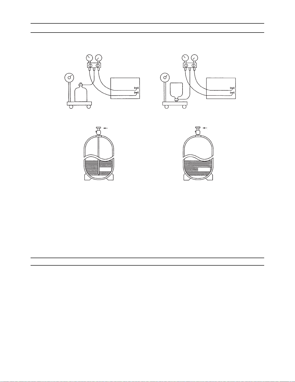
[9] Refrigerant Charging
Cylinder with a siphon
Cylinder without a siphon
Cylin-
Cylin-
der
der
Cylinder color R410A is pink. Refrigerant charging in the liquid state
Valve Valve
liquid
liquid
1. Reasons
R410A is a pseudo-azeotropic HFC blend (boiling point R32=-52°C[-62°F], R125=-49°C[-52°F]) and can almost be handled
the same way as a single refrigerant, such as R22. To be safe, however, draw out the refrigerant from the cylinder in the liquid
phase. If the refrigerant in the gaseous phase is drawn out, the composition of the remaining refrigerant will change and become unsuitable for use.
2. Notes
When using a cylinder with a siphon, refrigerant is charged in the liquid state without the need for turning it upside down. Check
the type of the cylinder on the label before use.
[10] Remedies to be taken in case of a Refrigerant Leak
If the refrigerant leaks out, it may be replenished. The entire refrigerant does not need to be replaced. (Charge refrigerant in the
liquid state.)
Refer to "IX [5] Refrigerant Leak."(page 274)
HWE09120 GB
- 11 -
Page 21

[ I Read Before Servicing ]
[11] Characteristics of the Conventional and the New Refrigerants
1. Chemical property
As with R22, the new refrigerant (R410A) is low in toxicity and chemically stable nonflammable refrigerant.
However, because the specific gravity of vapor refrigerant is greater than that of air, leaked refrigerant in a closed room will
accumulate at the bottom of the room and may cause hypoxia.
If exposed to an open flame, refrigerant will generate poisonous gases. Do not perform installation or service work in a confined area.
New Refrigerant (HFC type) Conventional Refriger-
ant (HCFC type)
R410A R407C R22
R32/R125 R32/R125/R134a R22
Composition (wt%) (50/50) (23/25/52) (100)
Type of Refrigerant Pseudo-azeotropic
Refrigerant
Non-azeotropic
Refrigerant
Single Refrigerant
Chloride Not included Not included Included
Safety Class A1/A1 A1/A1 A1
Molecular Weight 72.6 86.2 86.5
Boiling Point (°C/°F) -51.4/-60.5 -43.6/-46.4 -40.8/-41.4
Steam Pressure
1.557/226 0.9177/133 0.94/136
(25°C,MPa/77°F,psi) (gauge)
Saturated Steam Density
(25°C,kg/m
3
/77°F,psi)
64.0 42.5 44.4
Flammability Nonflammable Nonflammable Nonflammable
Ozone Depletion Coefficient (ODP)
Global Warming Coefficient (GWP)
Refrigerant Charging Method Refrigerant charging in
Replenishment of Refrigerant after a Refrigerant
*1
*2
0 0 0.055
1730 1530 1700
the liquid state
Refrigerant charging in
the liquid state
Refrigerant charging in
the gaseous state
Available Available Available
Leak
*1 When CFC11 is used as a reference
*2 When CO
is used as a reference
2
2. Refrigerant composition
R410A is a pseudo-azeotropic HFC blend and can almost be handled the same way as a single refrigerant, such as R22. To
be safe, however, draw out the refrigerant from the cylinder in the liquid phase. If the refrigerant in the gaseous phase is drawn
out, the composition of the remaining refrigerant will change and become unsuitable for use.
If the refrigerant leaks out, it may be replenished. The entire refrigerant does not need to be replaced.
3. Pressure characteristics
The pressure in the system using R410A is 1.6 times as great as that in the system using R22.
Pressure (gauge)
Temperature (°C/°F)
R410A R407C R22
MPa/psi MPa/psi MPa/psi
-20/-4 0.30/44 0.18/26 0.14/20
0/32 0.70/102 0.47/68 0.40/58
20/68 1.34/194 0.94/136 0.81/117
40/104 2.31/335 1.44/209 1.44/209
60/140 3.73/541 2.44/354 2.33/338
65/149 4.17/605 2.75/399 2.60/377
HWE09120 GB
- 12 -
Page 22
[ I Read Before Servicing ]
[12] Notes on Refrigerating Machine Oil
1. Refrigerating machine oil in the HFC refrigerant system
HFC type refrigerants use a refrigerating machine oil different from that used in the R22 system.
Note that the ester oil used in the system has properties that are different from commercially available ester oil.
Refrigerant Refrigerating machine oil
R22 Mineral oil
R407C Ester oil
R410A Ester oil
2. Effects of contaminants
*1
Refrigerating machine oil used in the HFC system must be handled with special care to keep contaminants out.
The table below shows the effect of contaminants in the refrigerating machine oil on the refrigeration cycle.
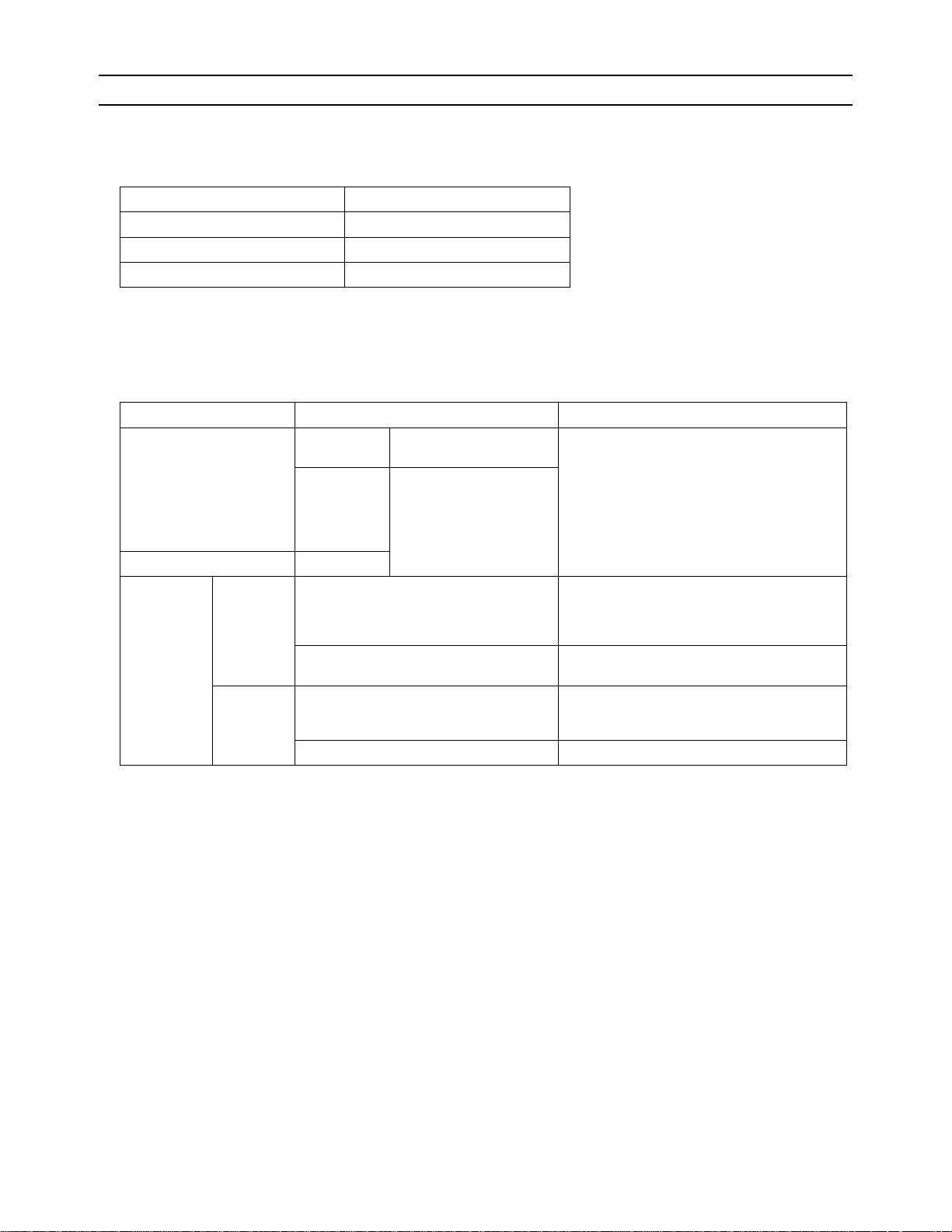
3. The effects of contaminants in the refrigerating machine oil on the refrigeration cycle.
Cause Symptoms Effects on the refrigerant cycle
Water infiltration Frozen expansion valve
and capillary tubes
Clogged expansion valve and capillary tubes
Poor cooling performance
Compressor overheat
Motor insulation failure
Burnt motor
Coppering of the orbiting scroll
Lock
Burn-in on the orbiting scroll
Clogged expansion valve, capillary tubes, and
drier
Hydrolysis
Air infiltration Oxidization
Adhesion to expansion valve and capillary
tubes
Sludge formation and adhesion
Acid generation
Oxidization
Oil degradation
Poor cooling performance
Infiltration of
contaminants
Dust, dirt
Infiltration of contaminants into the compressor
Compressor overheat
Burn-in on the orbiting scroll
Sludge formation and adhesion Clogged expansion valve and capillary tubes
Mineral oil
etc.
Poor cooling performance
Compressor overheat
Oil degradation Burn-in on the orbiting scroll
*1. Contaminants is defined as moisture, air, processing oil, dust/dirt, wrong types of refrigerant, and refrigerating machine oil.
HWE09120 GB
- 13 -
Page 23

[ I Read Before Servicing ]
- 14 -
GBHWE09120
Page 24

II
Restrictions
[1] System configuration ....................................................................................................... 17
[2] Types and Maximum allowable Length of Cables ........................................................... 18
[3] Switch Settings and Address Settings ............................................................................. 19
[4] Sample System Connection............................................................................................. 26
[5] An Example of a System to which an MA Remote Controller is connected..................... 28
[6] An Example of a System to which an ME Remote Controller is connected.....................38
[7] An Example of a System to which both MA Remote Controller and
ME Remote Controller are connected.............................................................................. 40
[8] Restrictions on Pipe Length ............................................................................................. 42
HWE09120 GB
- 15 -
Page 25

- 16 -
Page 26

[ II Restrictions ]
II Restrictions
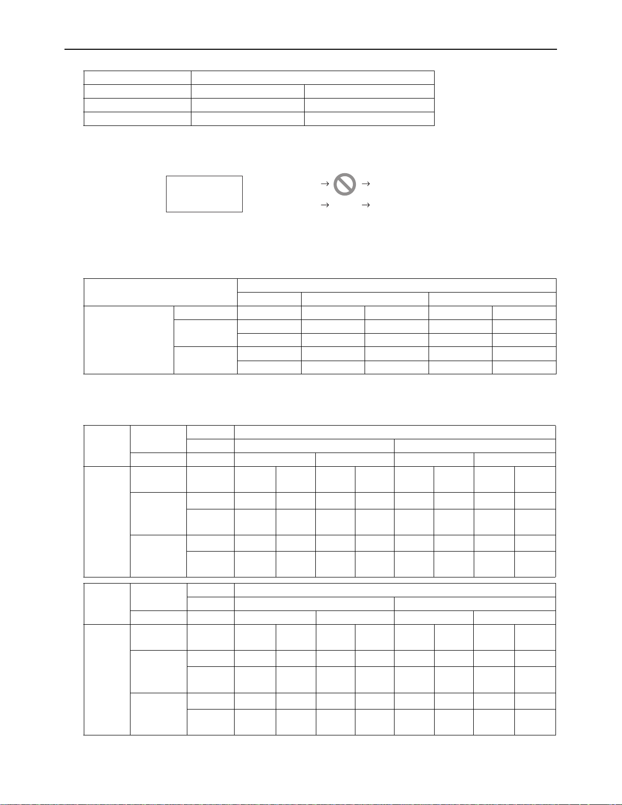
[1] System configuration
1. Table of compatible indoor units
The table below summarizes the types of indoor units that are compatible with different types of outdoor units.
Outdoor
units
Composing units Maximum total capacity
of connectable indoor
units
Maximum number
of connectable in-
door units
Types of connectable in-
door units
72 - - - 36 - 93 15 P06 - P96models
96 - - - 48 - 124 20
R410A series indoor units
120 - - - 60 - 156 26
144 - - - 72 - 187 31
168 96 72 - 84 - 218 36
192 120 72 - 96 - 249 41
216 120 96 - 108 - 280 46
240 120 120 - 120 - 312 50
264 144 120 - 132 - 343
288 144 144 - 144 - 374
312 120 120 72 156 - 405
336 120 120 96 168 - 436
360 144 120 96 180 - 468
1) "Maximum total capacity of connectable indoor units" refers to the sum of the numeric values in the indoor unit model names.
2) If the total capacity of the indoor units that are connected to a given outdoor unit exceeds the capacity of the outdoor unit, the
indoor units will not be able to perform at the rated capacity when they are operated simultaneously. Select a combination of
units so that the total capacity of the connected indoor units is at or below the capacity of the outdoor unit whenever possible.
HWE09120 GB
- 17 -
Page 27

[ II Restrictions ]
TB 3 TB 7 TB 3 TB
7
TB
3
TB 3 TB
7
TB
7
TB 3 TB
7
TB
3
TB
7
TB 3 TB 7 TB 3 TB
7
TB
3
TB 3 TB
7
TB
7
TB 3 TB
7
TB
3
TB
7
2-core shielded cable
2-core shielded cable
Indoor unit
Outdoor unit
TB3: Terminal block for indoor-outdoor transmission line TB7: Terminal block for centralized control
Remote Controller
Indoor unit
Outdoor unit
Remote Controller
multiple-core cable
[2] Types and Maximum allowable Length of Cables
1. Wiring work
(1) Notes
1) Have all electrical work performed by an authorized electrician according to the local regulations and instructions in this manual.
2) Install external transmission cables at least 5cm [1-31/32"] away from the power supply cable to avoid noise interference.
(Do not put the control cable and power supply cable in the same conduit tube.)
3) Provide grounding for the outdoor unit as required.
4) Run the cable from the electric box of the indoor or outdoor unit in such way that the box is accessible for servicing.
5) Do not connect power supply wiring to the terminal block for transmission line. Doing so will damage the electronic components on the terminal block.
6) Use 2-core shielded cables as transmission cables.
Use a separate 2-core control cable for each refrigerant system. Do not use a single multiple-core cable to connect indoor
units that belong to different refrigerant systems. The use of a multiple-core cable may result in signal transmission errors and
malfunctions.
(2) Control wiring
Different types of control wiring are used for different systems.
Refer to section "[5] An Example of a System to which an MA Remote Controller is connected - [7] An Example of a System
to which both MA Remote Controller and ME Remote Controller are connected" before performing wiring work.
Types and maximum allowable length of cables
Control lines are categorized into 2 types: transmission line and remote controller line.
Use the appropriate type of cables and observe the maximum allowable length specified for a given system. If a given system
has a long transmission line or if a noise source is located near the unit, place the unit away from the noise source to reduce
noise interference.
1) M-NET transmission line
Cable type
Maximum transmission
line distance between the
outdoor unit and the farthest indoor unit
Maximum transmission
line distance for centralized control and Indoor/
outdoor transmission line
(Maximum line distance
via outdoor unit)
Facility
type
All facility types
Type Shielded cable CVVS, CPEVS, MVVS
Number of
cores
Cable size Larger than 1.25mm
500 m [1640ft] max.
*The maximum overall line length from the power supply unit on the transmission lines for
2-core cable
2
[AWG16]
200 m [656ft] max.
centralized control to each outdoor unit or to the system controller is 200m [656ft] max.
HWE09120 GB
- 18 -
Page 28

[ II Restrictions ]
2) Remote controller wiring
MA remote controller
*1
ME remote controller
Type CVV CVV
Number of
cores
Cable type
Cable size
Maximum overall line
length
2-core cable 2-core cable
0.3 to 1.25mm
[AWG22 to 16]
(0.75 to 1.25mm
[AWG18 to 16]
2 *2
2 ) *3
0.3 to 1.25mm
[AWG22 to 16]
(0.75 to 1.25mm2 )
[AWG18 to 16]
The section of the cable that exceeds 10m
200 m [656ft] max.
[32ft] must be included in the maximum indoor-outdoor transmission line distance.
2 *2
*3
*1 MA remote controller refers to MA remote controller (PAR-20MAU, PAR-21MAA), MA simple remote controller, and
wireless remote controller.
*2 The use of cables that are smaller than 0.75mm
2
(AWG18) is recommended for easy handling.
*3 When connected to the terminal block on the Simple remote controller, use cables that meet the cable size specifi-
cations shown in the parenthesis.
[3] Switch Settings and Address Settings
1. Switch setting
Refer to section "[5] An Example of a System to which an MA Remote Controller is connected - [7] An Example of a System
to which both MA Remote Controller and ME Remote Controller are connected" before performing wiring work.
Set the switches while the power is turned off.
If the switch settings are changed while the unit is being powered, those changes will not take effect, and the unit will not
function properly.
Units on which to set the switches Symbol Units to which the power must be shut off
*3
CITY MULTI indoor unit Main/sub unit IC Outdoor units
LOSSNAY, OA processing unit
*1
LC Outdoor units
Air handling kit IC Outdoor units
and Indoor units
*3
and LOSSNAY
*3
or field supplied air handling
unit
ME remote controller Main/sub remote
RC Outdoor units
*3
controller
MA remote controller Main/sub remote
MA Indoor units
controller
CITY MULTI outdoor unit
*2
OC,OS1,OS2 Outdoor units
*3
*1. Applicable when LOSSNAY units are connected to the indoor-outdoor transmission line.
*2. The outdoor units in the same refrigerant circuit are automatically designated as OC, OS1, and OS2 in the order of
capacity from large to small (if two or more units have the same capacity, in the order of address from small to large).
*3. Turn off the power to all the outdoor units in the same refrigerant circuit.
HWE09120 GB
- 19 -
Page 29

[ II Restrictions ]
2. M-NET Address settings
(1) Address settings table
The need for address settings and the range of address setting depend on the configuration of the system.
Unit or controller Symbol Address set-
Setting method Facto-
ting range
CITY MULTI indoor unit
M-NET adapter
Main/sub unit IC 00,
01 to 50
Assign the smallest address to the main indoor
*1
unit in the group, and assign sequential address
numbers to the rest of the indoor units in the
same group.
*4
M-NET control interface
Free Plan adapter
LOSSNAY, OA processing unit
Air handling kit
LC 00,
01 to 50
Assign an arbitrary but unique address to each
*1
of these units after assigning an address to all
indoor units.
ME remote controller
Main remote
controller
Sub remote
controller
RC 101 to 150 Add 100 to the smallest address of all the in-
door units in the same group.
RC 151 to 200
*2
Add 150 to the smallest address of all the indoor units in the same group.
MA remote controller MA No address settings required. (The main/sub setting must be
made if 2 remote controllers are connected to the system.)
CITY MULTI outdoor unit OC,
OS1,
System controller Group remote
controller
00,
51 to 100
OS2
Assign sequential addresses to the outdoor
*1,*3
units in the same refrigerant circuit. The outdoor units in the same refrigerant circuit are
automatically designated as OC and OS.
*5
GR,SC201 to 250 Assign an address that equals the sum of the
smallest group number of the group to be controlled and 200.
System remote
controller
ON/OFF remote controller
SR,
SC
AN,
SC
Assign an arbitrary but unique address within
the range listed on the left to each unit.
Assign an address that equals the sum of the
smallest group number of the group to be controlled and 200.
Schedule timer
(compatible
ST,
SC
Assign an arbitrary but unique address within
the range listed on the left to each unit.
with M-NET)
Centralized
controller
AG-150A
TR,SC000
201 to 250
Assign an arbitrary but unused address within
the range listed on the left to each unit. Be sure
to set it to "000" to control K-control units.
G(B)-50A
GB-24A
Expansion
controller
PAC-
TR 000
201 to 250
Assign an arbitrary but unused address within
the range listed on the left to each unit. Be sure
to set it to "000" to control K-control units.
YG50ECA
BM adapter
BAC-HD150
SC 000
201 to 250
Assign an arbitrary but unused address within
the range listed on the left to each unit. Be sure
to set it to "000" to control K-control units.
LM adapter
LMAP03U
SC 201 to 250 Assign an arbitrary but unique address within
the range listed on the left to each unit.
ry set-
ting
00
00
101
Main
00
201
202
000
000
000
247
*1. Address setting is not required for a City Multi system that consists of a single refrigerant circuit (with some exceptions).
*2. To set the ME remote controller address to "200", set the rotary switches to "00".
*3. To set the outdoor unit address to "100," set the rotary switches to "50."
*4. Some indoor units have 2 or 3 controller boards that require address settings.
No. 2 controller board address must be equal to the sum of the No. 1 controller board address and 1, and the No.3
controller board address must equal to the No. 1 controller address and 2.
*5. The outdoor units in the same refrigerant circuit are automatically designated as OC, OS1, and OS2 in the order of
capacity from large to small (if two or more units have the same capacity, in the order of address from small to large).
HWE09120 GB
- 20 -
Page 30

[ II Restrictions ]
(2) Power supply switch connector connection on the outdoor unit
(Factory setting: The male power supply switch connector is connected to CN41.)
System configuration
Connection to
the system controller
Power supply unit
for transmission
lines
Group operation
of units in a system with multiple
Power supply switch connector connection
outdoor units
System with
one outdoor unit
System with
multiple outdoor
units
_ _ _ Leave CN41 as it is
(Factory setting)
Not connected _ Not grouped
Grouped Disconnect the male connector from the fe-
With connection
to the indoor
unit system
With connection
to the centralized control
system
Not required Grouped/not
grouped
Not required
(Powered from the
*1
Grouped/not
grouped
outdoor unit)
Required *
1
Grouped/not
grouped
male power supply switch connector (CN41)
and connect it to the female power supply
switch connector (CN40) on only one of the
outdoor units.
*Connect the S (shielded) terminal on the ter-
minal block (TB7) on the outdoor unit whose
CN41 was replaced with CN40 to the
ground terminal ( ) on the electric box.
Leave CN41 as it is
(Factory setting)
*2
*1 The need for a power supply unit for transmission lines depends on the system configuration.
*2 The replacement of the power jumper connector from CN41 to CN40 must be performed on only one outdoor unit in the
system.
(3) Settings for the centralized control switch for the outdoor unit (Factory setting: SW2-1 are set to OFF.)
System configuration Centralized control switch settings *
1
Connection to the system controller Not connected Leave it to OFF. (Factory setting)
Connection to the system controller Connected *
2
ON
*1 Set SW2-1 on all outdoor units in the same refrigerant circuit to the same setting.
*2 When only the LM adapter is connected, leave SW2-1 to OFF (as it is).
(4) Selecting the position of temperature detection for the indoor unit (Factory setting: SW1-1 set to "OFF".)
To stop the fan during heating Thermo-OFF (SW1-7 and 1-8 on the indoor units to be set to ON), use the built-in thermistor
on the remote controller or an optional thermistor.
1) To use the built-in sensor on the remote controller, set the SW1-1 to ON.
Some models of remote controllers are not equipped with a built-in temperature sensor.
Use the built-in temperature sensor on the indoor unit instead.
When using the built-in sensor on the remote controller, install the remote controller where room temperature can be detected.
(Note) Factory setting for SW1-1 on the indoor unit of the All-Fresh Models is ON.
2) When an optional temperature sensor is used, set SW1-1 to OFF, and set SW3-8 to ON.
When using an optional temperature sensor, install it where room temperature can be detected.
(5) Various start-stop controls (Indoor unit settings)
Each indoor unit (or group of indoor units) can be controlled individually by setting SW 1-9 and 1-10.
Function
Power ON/OFF by
the plug
*1,*2,*3
Automatic restoration
after power failure
Operation of the indoor unit when the operation is resumed after the unit was
stopped
Indoor unit will go into operation regardless of its operation status before power
off (power failure). (In approx. 5 minutes)
Indoor unit will go into operation if it was in operation when the power was
turned off (or cut off due to power failure). (In approx. 5 minutes)
Indoor unit will remain stopped regardless of its operation status before power
Setting (SW1)
910
OFF ON
ON OFF
OFF ON
off (power failure).
*1. Do not cut off power to the outdoor unit. Cutting off the power supply to the outdoor unit will cut off the power supply to the
crankcase heater and may cause the compressor to malfunction when the unit is put back into operation.
*2. Not applicable to units with a built-in drain pump or humidifier.
*3. Models with a built-in drain pump cannot be turned on/off by the plug individually. All the units in the same refrigerant cir-
cuits will be turned on or off by the plug.
*4. Requires that the dipswitch settings for all the units in the group be made.
*5. To control the external input to and output from the air conditioners with the PLC software for general equipment via the
G(B)-50A, set SW1-9 and SW1-10 to ON. With these settings made, the power start-stop function becomes disabled. To
use the auto recovery function after power failure while these settings are made, set SW1-5 to ON.
*4 *5
HWE09120 GB
- 21 -
Page 31

[ II Restrictions ]
CAUTION
(6) Miscellaneous settings
Cooling-only setting for the indoor unit: Cooling only model (Factory setting: SW3-1 "OFF.")
When using indoor unit as a cooling-only unit, set SW3-1 to ON.
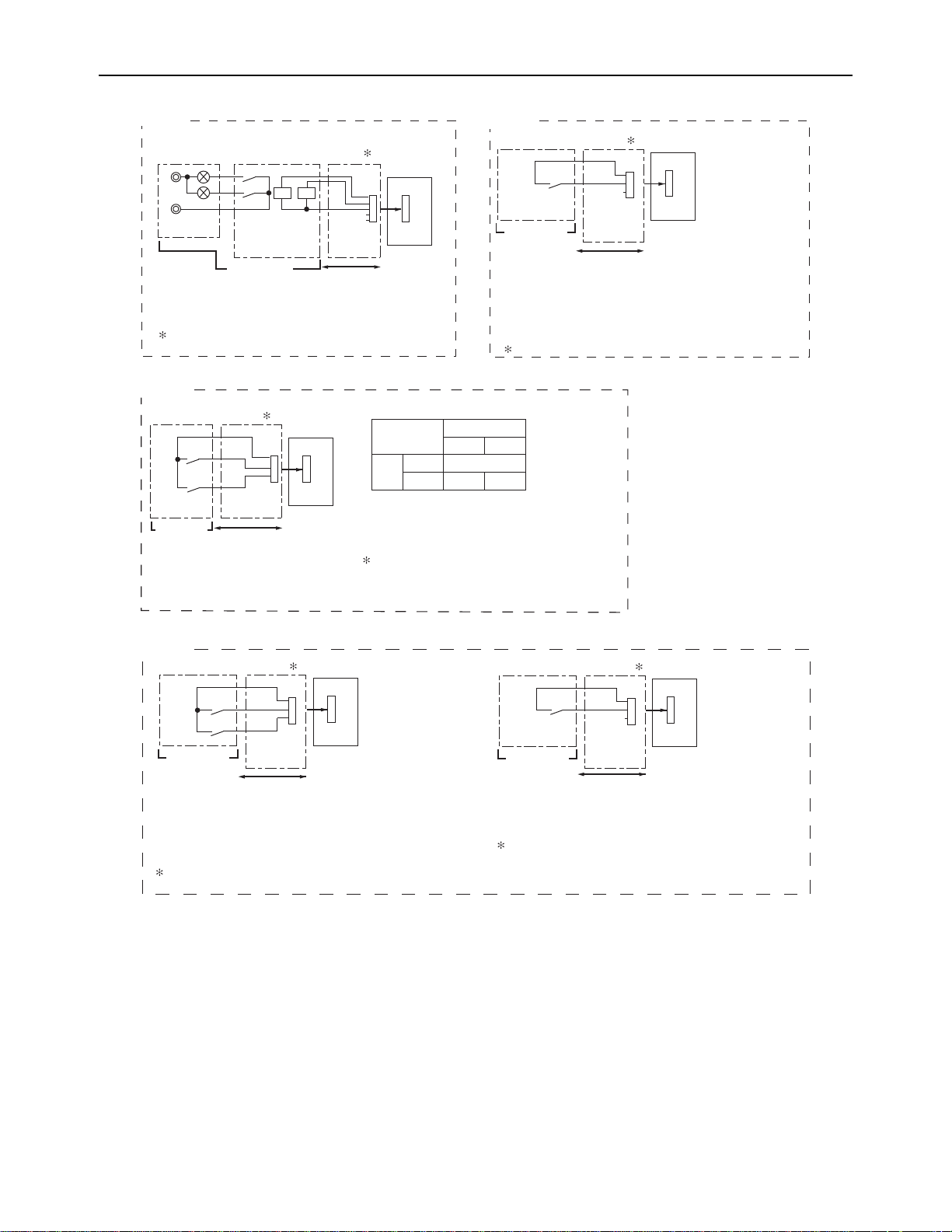
(7) Various types of control using input-output signal connector on the outdoor unit (various connection options)
Type Usage Function
Input Prohibiting cooling/heating operation (thermo OFF) by an external
DEMAND (level) CN3D
input to the outdoor unit.
*It can be used as the DEMAND control device for each system.
Performs a low level noise operation of the outdoor unit by an external input to the outdoor unit.
Low-noise mode
*3*4
(level)
to be
used
*1
*2
Option
Adapter for
external input
(PACSC36NA-E)
Terminal
* It can be used as the silent operation device for each refrigerant
system.
Forces the outdoor unit to perform a fan operation by receiving signals from the snow sensor.
*5
Cooling/heating operation can be changed by an external input to
Snow sensor signal
CN3S
input (level)
Auto-changeover CN3N
the outdoor unit.
Out-
How to extract signals from the outdoor unit
put
*It can be used as an operation status display device.
*It can be used for an interlock operation with external devices.
Operation status of
the compressor
Error status
*5
*6
CN51 Adapter for
external output
(PACSC37SA-E)
*1. For detailed drawing, refer to "Example of wiring connection".
*2. For details, refer to (1) through (4) shown below.
*3. Low-noise mode is valid when Dip SW4-4 on the outdoor unit is set to OFF. When DIP SW4-4 is set to ON, 4 levels of
on-DEMAND are possible, using different configurations of low-noise mode input and DEMAND input settings.When 2
or more outdoor units exist in one refrigerant circuit system, 8 levels of on-DEMAND are possible. When 3 outdoor units
exist in one refrigerant circuitsystem, 12 levels of on-DEMAND are possible.
*4. By setting Dip SW5-5, the Low-noise mode can be switched between the Capacity priority mode and the Low-noise pri-
ority mode.
When SW5-5 is set to ON: The Low-noise mode always remains effective.
When SW5-5 is set to OFF: The Low-noise mode is cancelled when certain outside temperature or pressure criteria are
met, and the unit goes into normal operation (capacity priority mode).
Low-noise mode is effective Capacity priority mode becomes effective
Cooling Heating Cooling Heating
TH7 < 30°C [86°F]
and
63HS1 < 32kg/cm
2
TH7 > 3°C [37°F]
and
63LS > 4.6kg/cm
TH7 > 35°C [95°F]
2
or
63HS1 > 35kg/cm
2
TH7 < 0°C [32°F]
or
63LS < 3.9kg/cm
2
*5. Each outdoor unit in the system with multiple outdoor units requires the signal input/output setting to be made.
*6. Take out signals from the outdoor unit (OC) if multiple outdoor units exist in a single system.
1) Wiring should be covered by insulation tube with supplementary insulation.
2) Use relays or switches with IEC or equivalent standard.
3) The electric strength between accessible parts and control circuit should have 2750V or more.
HWE09120 GB
- 22 -
Page 32
[ II Restrictions ]
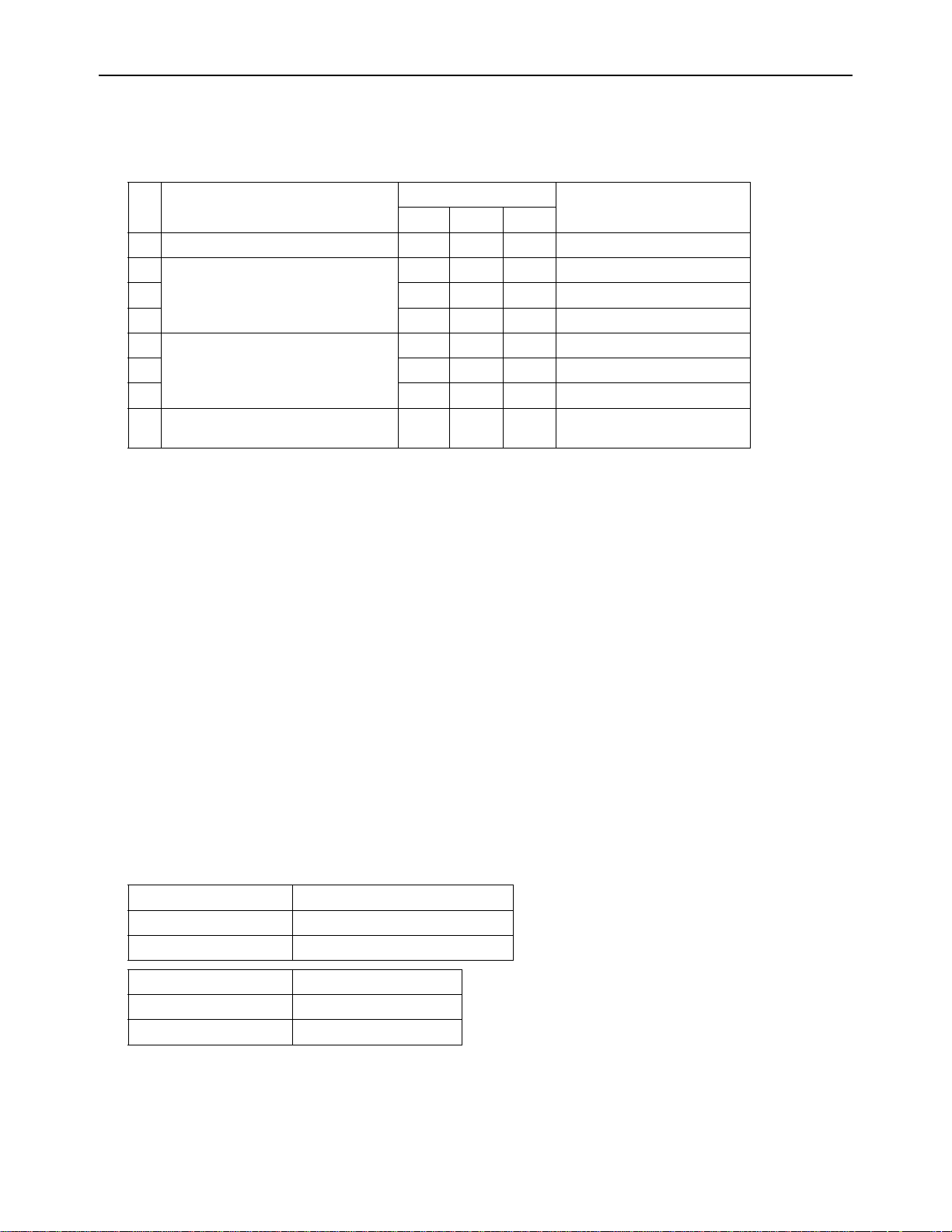
(1) CN51
(2) CN3S
CN51
X
Y
L
1
L
2
ecruos rewop pmaL
Distant control
board
Relay circuit Adapter
1
Outdoor unit
control board
Preparations
in the field
Maximum cable
length is 10m
5
4
3
X
Y
L1 : Outdoor unit error display lamp
L2 : Compressor operation lamp (compressor running state)
X, Y : Relay (coil =<0.9W : DC12V)
1. Optional part : PAC-SC37SA-E or field supply.
2. Optional part : PAC-SC36NA-E or field supply.
X : Relay
Snow sensor : The outdoor fan runs when X is closed
in stop mode or thermostat mode.
X
CN3S
Preparations
in the field
Maximum cable
length is 10m
Adapter
2
Outdoor unit
control board
2
3
1
Contact rating voltage >= DC15V
Contact rating current >= 0.1A
Minimum applicable load =< 1mA at DC
Relay circuit
(3) CN3N
2. Optional part : PAC-SC36NA-E or field supply.
Preparations
in the field
OFF
CoolingONHeating
Normal
Y
OFF
ON
X
Contact rating voltage >= DC15V
Contact rating current >= 0.1A
Minimum applicable load =< 1mA at DC
X : Cooling / Heating
Y : Validity / Invalidity of X
X,Y : Relay
CN3N
X
Y
Relay circuit
Adapter
2
Outdoor unit
control board
Maximum cable
length is 10m
1
2
3
Example of wiring connection
(4) CN3D
Relay circuit
X
Preparations
in the field
Y
X : Low-noise mode
Y : Compressor ON/OFF
X,Y : Relay
2. Optional part : PAC-SC36NA-E or field supply.
Adapter
Maximum cable
length is 10m
Contact rating voltage >= DC15V
Contact rating current >= 0.1A
Minimum appicable load =< 1mA at DC
2
1
2
3
Outdoor unit
control board
CN3D
1
2
3
Outdoor unit
2
control board
CN3D
Relay circuit
X
Preparations
in the field
X : Low-noise mode
X : Relay
Contact rating voltage >= DC15V
Contact rating current >= 0.1A
Minimum applicable load =< 1mA at DC
Adapter
Maximum cable
length is 10m
2. Optional part : PAC-SC36NA-E or field supply.
Low-noise mode : The noise level is reduced by controlling the maximum
fan frequency and maximum compressor frequency.
HWE09120 GB
- 23 -
Page 33
[ II Restrictions ]
3. Demand control
(1) General outline of control
Demand control is performed by using the external signal input to the 1-2 and 1-3 pins of CN3D on the outdoor units (OC,
OS1, and OS2).
Between 2 and 12 steps of demand control is possible by setting DIP SW4-4 on the outdoor units (OC, OS1, and OS2).
No Demand control switch
Input to CN3D *2
OC OS1 OS2
(a) 2 steps(0-100%) OFF OFF OFF OC
(b) 4 steps(0-50-75-100%) ON OFF OFF OC
(c) OFF ON OFF OS1
(d) OFF OFF ON OS2
(e) 8 steps(0-25-38-50-63-75-88-100%) ON ON OFF OC and OS1
(f) ON OFF ON OC and OS2
(g) OFF ON ON OS1 and OS2
DipSW4-4
(h) 12 steps(0-17-25-34-42-50-59-67-75-
ON ON ON OC, OS1, and OS2
84-92-100%)
*1. Available demand functions
P72-P144T(Y)JMU models (single-outdoor-unit system): 2 and 4 steps shown in the rows (a) and (b) in the table above
only.
P168-P288T(Y)SJMU models (two-outdoor-unit system OC+OS1): 2-8 steps shown in the rows (a), (b), (c), and (e) in the
table above only.
P312-P360T(Y)SJMU models (three-outdoor-unit system OC+OS1+OS2): 2-12 steps shown in the rows (a)-(h) in the table
above.
*2. External signal is input to CN3D on the outdoor unit whose SW4-4 is set to ON. When SW4-4 is set to OFF on all outdoor
units, the signal is input to the CN3D on the OC.
Outdoor units whose SW4-4 is set to ON are selectable in a single refrigerant system.
*3. If wrong sequence of steps are taken, the units may go into the Thermo-OFF (compressor stop) mode.
Ex) When switching from 100% to 50%
(Incorrect) 100% to 0% to 50% : The units may go into the Thermo-OFF mode.
(Correct) 100% to 75% to 50%
*4. The percentage of the demand listed in the table above is an approximate value based on the compressor volume and
does not necessarily correspond with the actual capacity.
*5. Notes on using demand control in combination with the low-noise mode
To enable the low-noise mode, it is necessary to short-circuit 1-2 pin of CN3D on the outdoor unit whose SW4-4 is set to
OFF.
When SW4-4 is set to ON on all outdoor units, the following operations cannot be performed.
Performing 4-step demand in combination with the low-noise operation in a single-outdoor-unit system.
Performing 8-step demand in combination with the low-noise operation in a two-outdoor-unit system.
Performing 12-step demand in combination with the low-noise operation in a three-outdoor-unit system.
(2) Contact input and control content
1) SW4-4: OFF (Compressor ON/OFF, Low-noise mode)
CN3D 1-3P Compressor ON/OFF
*1
Open Compressor ON
Short-circuit Compressor OFF
CN3D 1-2P Low-noise mode
*2
Open OFF
Short-circuit ON
*1. When SW4-4 on the outdoor unit in one refrigerant circuit system is set to ON , this function cannot be used.
*2. This function and the 4 levels or 8 levels on-DEMAND function can be used together. Input the order to CN3D 1-2P on
the outdoor unit whose SW4-4 is set to OFF.
HWE09120 GB
- 24 -
Page 34
[ II Restrictions ]
If the step listed as the wrong example above is taken, thermo may go off.
The percentage of the demand listed in the table above is an approximate value based on the
compressor volume and does not necessarily correspond with the capacity.
When this function is enabled, the night mode cannot be enabled.
(Wrong)
(Correct)
100%
100%
0%
75%
50%
50%
Demand control
steps
Note the following steps to be taken when using the STEP DEMAND
(Example) When switching from 100% to 50%
2) When SW4-4 on one outdoor unit in one refrigerant circuit system is set to ON (4 levels of on-DEMAND)
(*3)
CN3D 1-2P
CN3D 1-3P Open Short-circuit
Open 100% (No DEMAND) 75%
Short-circuit 0% (Compressor OFF) 50%
*3. Input the order to CN3D on the outdoor unit whose SW4-4 is set to ON.
3) When SW4-4 on the two outdoor units in one refrigerant circuit system is set to ON (8 levels of on-DEMAND)
8 levels of on-DEMAND No.2 CN3D
1-2P Open Short-circuit
No.1 CN3D 1-2P 1-3P Open Short-circuit Open Short-circuit
Open Open 100% 50% 88% 75%
Short-circuit 50% 0% 38% 25%
Short-circuit Open 88% 38% 75% 63%
Short-circuit 75% 25% 63% 50%
(*4, *5)
*4. Input the order to CN3D on the outdoor unit whose SW4-4 is set to ON.
*5. CN3D of No. 1, 2, 3 can be selected arbitrary with the outdoor unit whose SW4-4 is set to ON.
4) When SW4-4 on the all outdoor units in one refrigerant circuit system is set to ON (12 levels of on-DEMAND)
12 levels
of on-DEMAND
No.1
CN3D
No.2 CN3D 1-2P Open
1-3P Open Short-circuit
No.3 CN3D 1-2P Open Short-circuit Open Short-circuit
1-2P 1-3P Open Short-
circuit
Open Open 100% 67% 92% 84% 67% 34% 59% 50%
Short-
67% 34% 59% 50% 34% 0% 25% 17%
circuit
Short-circuit Open 92% 59% 84% 75% 59% 25% 50% 42%
Short-
84% 50% 75% 67% 50% 17% 42% 34%
circuit
12 levels
of on-DEMAND
No.1
CN3D
No.2 CN3D 1-2P Short-circuit
1-3P Open Short-circuit
No.3 CN3D 1-2P Open Short-circuit Open Short-circuit
1-2P 1-3P Open Short-
circuit
Open Open 92% 59% 84% 75% 84% 50% 75% 67%
Short-
59% 25% 50% 42% 50% 17% 42% 34%
circuit
*3. Input the order to CN3D on the outdoor unit whose SW4-4 is set to ON.
*4. CN3D of No. 1, 2, 3 can be selected arbitrary with the outdoor unit whose SW4-4 is set to ON.
HWE09120 GB
Short-circuit Open 84% 50% 75% 67% 75% 42% 67% 59%
Shortcircuit
75% 42% 67% 59% 67% 34% 59% 50%
- 25 -
Open Short-
circuit
Open Short-
circuit
Open Short-
circuit
Open Short-
circuit
(*4)
Open Short-
circuit
Open Short-
circuit
Page 35
[ II Restrictions ]
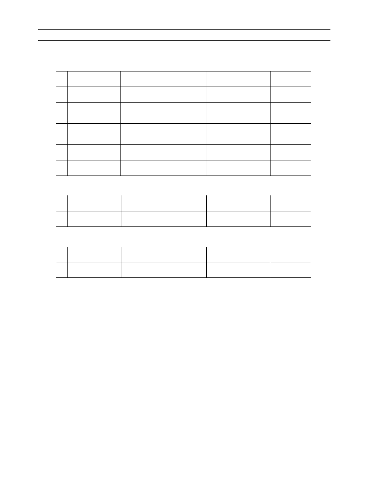
[4] Sample System Connection
Examples of typical system connection are shown on pages [5] to [7].
Refer to the Installation Manual that came with each device or controller for details.
(1) An example of a system to which an MA remote controller is connected
System
configuration
System with one out-
1.
2.
door unit
System with one out-
door unit
Grouping of units in a
3.
system with multiple
outdoor units
System with one out-
4.
5.
door unit
System with one out-
door unit
Connection to the system controller
NO
NO
NO
With connection to transmission line
for centralized control
With connection to indoor-outdoor
transmission line
Address start up for in-
door and outdoor units
Automatic
address setup
Manual
address setup
Manual
address setup
Manual
address setup
Manual
address setup
Notes
Connection of
multiple LOSSNAY units
(2) An example of a system to which an ME remote controller is connected
System
configuration
System with one out-
1.
door unit
Connection to the system controller
With connection to transmission line
for centralized control
Address start up for indoor
and outdoor units
Manual
address setup
Notes
(3) An example of a system to which both MA remote controller and ME remote controller are connected
System
configuration
System with one out-
1.
door unit
Connection to the system controller
With connection to transmission
line for centralized control
Address start up for indoor and outdoor units
Manual
address setup
Notes
HWE09120 GB
- 26 -
Page 36

[ II Restrictions ]
HWE09120 GB
- 27 -
Page 37
[ II Restrictions ]
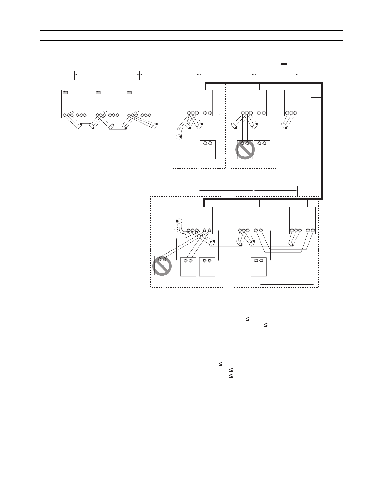
[5] An Example of a System to which an MA Remote Controller is connected
1. System with one outdoor unit (automatic address setup for both indoor and outdoor units)
(1) Sample control wiring
Leave the male
connector on
CN41 as it is.
SW2-1 OFF
Leave the male
connector on
CN41 as it is.
SW2-1 OFF
OS1 OS2
Leave the male
connector on
CN41 as it is.
SW2-1 OFF
00
TB3
TB7
M1 M2 M1 M2 M1 M2 M1 M2 M1 M2 M1 M2
TB3
S
TB7
TB3
S
OC
00 00
TB7
L2 L1
Group Group
IC
00
TB5 S TB
S
L3 L4
IC
00
15
1 2
m1
TB5 S TB
15
1 2
Interlock operation with
the ventilation unit
LC
00
TB5
M1 M2 M1 M2 M1 M2
S
L11
m4
A B
MA
(2) Cautions
1) ME remote controller and MA remote controller cannot
both be connected to the same group of indoor units.
2) No more than 2 MA remote controllers can be connected
to a group of indoor units.
3) A transmission booster is required in a system to which
more than 32 indoor units (26 units if one or more indoor
units of the 72 model or above is connected) are connected.
4) Automatic address setup is not available if start-stop input (CN32, CN51, CN41) is used for a group operation of
indoor units. Refer to "[5] 2. Manual address setup for
both indoor and outdoor units".(page 30)
5) To connect more than 2 LOSSNAY units to indoor units
in the same system, refer to "[5] 2. An example of a system with one outdoor unit to which 2 or more LOSSNAY
units are connected".(page 30)
A B
MA
L12 L13
Group Group
IC
A B
RC
IC
A B
MA
00 00
15
TB
TB5
M1 M2 M1 M2 M1 M2
S 1 2
m5
MA
A B
MA
A B
TB5 S TB
15
1 2
A B
MA
m2
m3
(3) Maximum allowable length
1) Indoor/outdoor transmission line
2
Maximum distance (1.25mm
[AWG16] or larger)
L1 +L2+L3+L4 200m[656ft]
L1 +L2+L11+L12+L13 200m[656ft]
2) Transmission line for centralized control
No connection is required.
3) MA remote controller wiring
Maximum overall line length
(0.3 to 1.25mm
2
[AWG22 to 16])
m1 200m [656ft]
m2+m3 200m [656ft]
m4+m5 200m [656ft]
IC
00
TB5 S TB
15
1 2
- 28 -
GBHWE09120
Page 38
[ II Restrictions ]
(4) Wiring method
1) Indoor/outdoor transmission line
Daisy-chain terminals M1 and M2 on the terminal block
for indoor-outdoor transmission line (TB3) on the outdoor
units (OC, OS1, OS2) (Note), and terminals M1 and M2
on the terminal block for indoor-outdoor transmission line
(TB5) on each indoor unit (IC). (Non-polarized two-wire)
Only use shielded cables.
The outdoor units in the same refrigerant circuit are automatically designated as OC, OS1, and OS2 in the order of capacity from large to small (if two or more units
have the same capacity, in the order of address from
small to large).
Shielded cable connection
Daisy-chain the ground terminal ( ) on the outdoor
units (OC, OS1, OS2), and the S terminal on the terminal
block (TB5) on the indoor unit (IC) with the shield wire of
the shielded cable.
2) Transmission line for centralized control
No connection is required.
3) MA remote controller wiring
Connect terminals 1 and 2 on the terminal block for MA
remote controller line (TB15) on the indoor unit (IC) to the
terminal block on the MA remote controller (MA). (Nonpolarized two-wire)
When 2 remote controllers are connected to the system
When 2 remote controllers are connected to the system,
connect terminals 1 and 2 of the terminal block (TB15) on
the indoor unit (IC) to the terminal block on the two MA
remote controllers.
Set one of the MA remote controllers to sub. (Refer to
(5) Address setting method
MA remote controller function selection or the installation
manual for the MA remote controller for the setting method.)
Group operation of indoor units
To perform a group operation of indoor units (IC), daisychain terminals 1 and 2 on the terminal block (TB15) on
all indoor units (IC) in the same group, and then connect
terminals 1 and 2 on the terminal block (TB15) on the indoor unit on one end to the terminal block on the MA remote controller. (Non-polarized two-wire)
When performing a group operation of indoor units that
have different functions, "Automatic indoor/outdoor address setup" is not available.
4) LOSSNAY connection
Connect terminals M1 and M2 on the terminal block
(TB5) on the indoor unit (IC) to the appropriate terminals
on the terminal block (TB5) on LOSSNAY (LC). (Non-polarized two-wire)
Interlock operation setting with all the indoor units in the
same system will automatically be made. (It is required
that the Lossnay unit be turned on before the outdoor
unit.)
Refer to "[5] 2. Manual address setup for both indoor and
outdoor units" in the following cases: performing an interlock operation of part of the indoor units in the system
with a LOSSNAY unit, using LOSSNAY alone without interlocking it with any units, performing an interlock operation of more than 16 indoor units with a LOSSNAY unit,
or connecting two or more LOSSNAY units to indoor
units in the same system.
5) Switch setting
No address settings required.
Proce-
dures
Unit or controller
1 Indoor unit Main unit IC No settings re-
Sub unit IC
Address setting
range
quired.
Setting
method
Notes
- To perform a group operation of indoor units that
have different functions,
Factory
setting
00
refer to [5] 2.(page 30)
2 LOSSNAY LC No settings re-
-00
quired.
3MA
remote controller
Main
remote controller
Sub
remote controller
MA No settings re-
quired.
MA Sub
remote controller
-Main
Settings to
be made according to
the remote
controller
function selection
4 Outdoor unit (Note) OC
OS1
No settings required.
-00
OS2
The outdoor units in the same refrigerant circuit are automatically designated as OC, OS1, and OS2.
The outdoor units are designated as OC, OS1, and OS2 in the order of capacity from large to small (if two or more units have
the same capacity, in the order of address from small to large).
HWE09120 GB
29- 29 -
Page 39

[ II Restrictions ]
2. An example of a system with one outdoor unit to which 2 or more LOSSNAY units are connected
(manual address setup for both indoor and outdoor units)
(1) Sample control wiring
Leave the male
connector on
CN41 as it is.
SW2-1 OFF
L1
Leave the male
connector on
CN41 as it is.
SW2-1 OFF
Leave the male
connector on
CN41 as it is.
SW2-1 OFF
53
TB3
TB3
TB7
M1 M2 M1 M2 M1 M2 M1 M2 M1 M2 M1 M2
S
TB7
TB3
S
L2
OC OS1 OS2
51 52
TB7
S
IC
01
TB5 S TB
M1 M2 M1 M2 M1 M2
L3 L4
Group Group
IC
02
15
1 2
TB5 S TB
15
1 2
TB5
Interlock operation with
the ventilation unit
LC
05
S
L11
(2) Cautions
1) ME remote controller and MA remote controller cannot
both be connected to the same group of indoor units.
2) No more than 2 MA remote controllers can be connected
to a group of indoor units.
3) A transmission booster is required in a system to which
more than 32 indoor units (26 units if one or more indoor
units of the 72 model or above is connected) are connected.
A B
MA
L12 L13
Group
IC
A B
MA
IC
04 03
TB5
S
15
TB
1 2
A B
MA
TB5 S TB
15
1 2
(3) Maximum allowable length
1) Indoor/outdoor transmission line
Same as [5] 1.
2) Transmission line for centralized control
No connection is required.
3) MA remote controller wiring
Same as [5] 1.
M1 M2 M1 M2 M1 M2
TB5
LC
06
S
- 30 -
GBHWE09120
Page 40

[ II Restrictions ]
(4) Wiring method
1) Indoor/outdoor transmission line
Same as [5] 1.
Shielded cable connection
Same as [5] 1.
2) Transmission line for centralized control
No connection is required.
3) MA remote controller wiring
Same as [5] 1.
When 2 remote controllers are connected to the system
Same as [5] 1.
Group operation of indoor units
Same as [5] 1.
(5) Address setting method
Proce-
dures
Unit or controller
1 Indoor unit Main
IC 01 to 50 Assign the smallest ad-
Address
setting
unit
Sub unit Assign sequential numbers
2 LOSSNAY LC 01 to 50 Assign an arbitrary but
3MA
remote controller
Main
remote
control-
MA No
settings required.
ler
Sub
remote
control-
MA Sub
remote
controller
ler
4 Outdoor unit OC
51 to 100 Assign sequential address
OS1
OS2
range
4) LOSSNAY connection
Connect terminals M1 and M2 on the terminal block
(TB5) on the indoor unit (IC) to the appropriate terminals
on the terminal block (TB5) on LOSSNAY (LC). (Non-polarized two-wire)
Interlock setting between the indoor units and LOSS-
NAY units must be entered on the remote controller. (Refer to "IV [3] Interlock Settings via the MA Remote
Controller" or the installation manual for the MA remote
controller for the setting method.)
5) Switch setting
Address setting is required as follows.
Setting method Notes
To perform a group operadress to the main unit in the
group.
tion of indoor units that
have different functions,
designate the indoor unit
starting with the address of
the main unit in the same
group +1. (Main unit ad-
in the group with the great-
est number of functions as
the main unit.
dress +1, main unit address +2, main unit
address +3, etc.)
None of these addresses
unique address to each of
these units after assigning
may overlap any of the in-
door unit addresses.
an address to all indoor
units.
-Main
Settings to be made according to the remote controller function selection
To set the address to 100,
to the outdoor units in the
same refrigerant circuit.
set the rotary switches to
50.
The outdoor units are automatically designated as
OC, OS1, and OS2.(Note)
Factory
setting
00
00
00
The outdoor units in the same refrigerant circuit are automatically designated as OC, OS1, and OS2.
The outdoor units are designated as OC, OS1, and OS2 in the order of capacity from large to small (if two or more units have
the same capacity, in the order of address from small to large).
HWE09120 GB
31- 31 -
Page 41
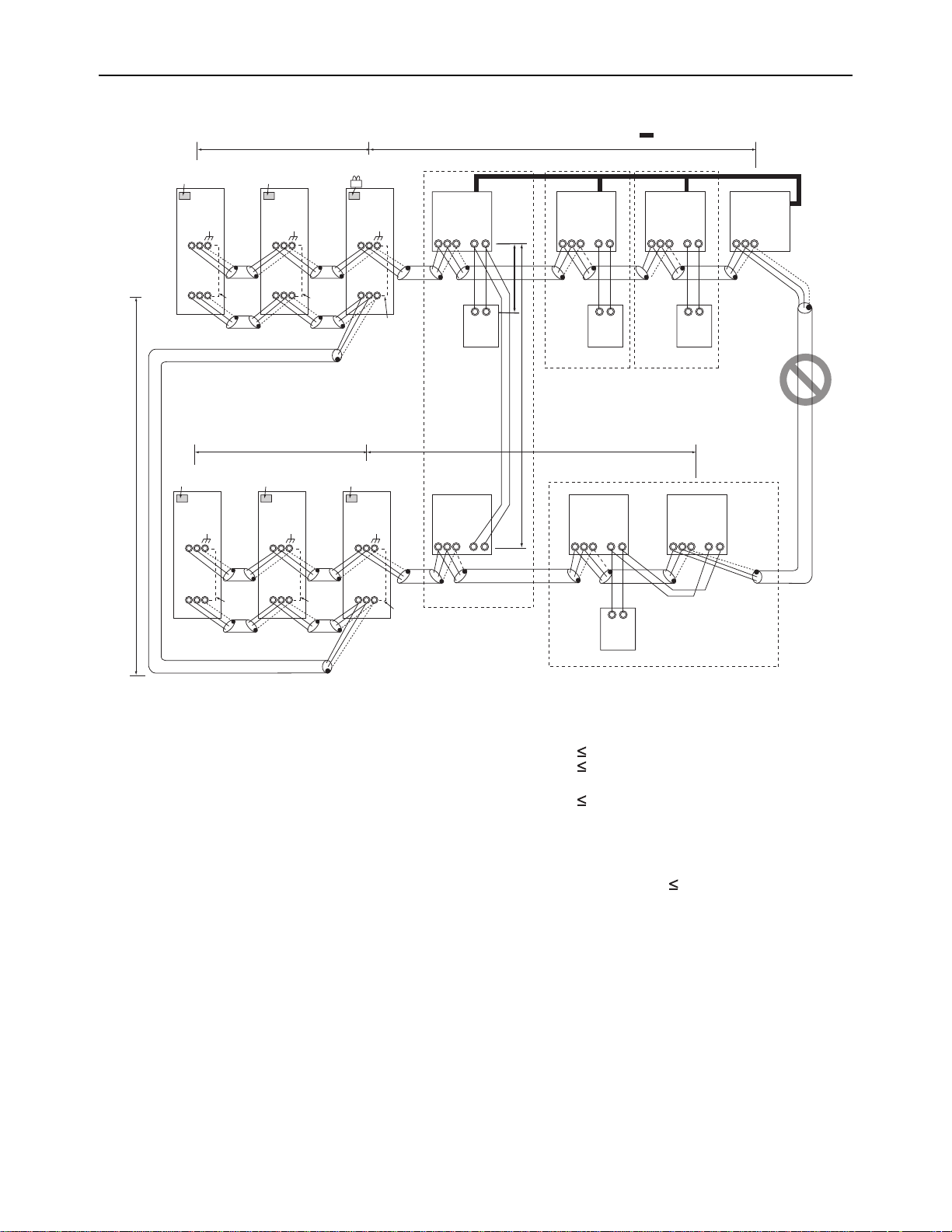
[ II Restrictions ]
3. Group operation of units in a system with multiple outdoor units
(1) Sample control wiring
L11
S
Leave the male
connector on
CN41 as it is.
SW2-1 OFF
To be left
unconnected
OS1
52
TB3
TB7
S
Leave the male
connector on
CN41 as it is.
SW2-1 OFF
OS2
53
TB3
M1 M2 M1 M2 M1 M2
TB7
M1 M2 M1 M2 M1 M2
To be left
unconnected
Move the male connector
from CN41 to CN40.
SW2-1 OFF
OC
51
TB3
TB7
S
To be connected
Group
IC
01
15
TB5 S TB
1 2
M1 M2 M1 M2 M1 M2 M1 M2
A B
m2
L12
Group
IC
03
TB5 S TB
15
1 2
A B
Interlock operation with
the ventilation unit
Group
IC
06
15
TB5 S TB
1 2
A B
TB5
LC
07
S
L31
Leave the male
connector on
CN41 as it is.
SW2-1 OFF
OS2
56
TB3
M1 M2 M1 M2 M1 M2
TB7
M1 M2 M1 M2 M1 M2
S
To be left
unconnected
L21
Leave the male
connector on
CN41 as it is.
SW2-1 OFF
55
TB3
TB7
OS1
S
Leave the male
connector on
CN41 as it is.
SW2-1 OFF
To be left
unconnected
54
TB3
TB7
OC
S
To be left
unconnected
TB5
M1 M2
(2) Cautions
1) ME remote controller and MA remote controller can not
both be connected to the same group of indoor units.
2) No more than 2 MA remote controllers can be connected
to a group of indoor units.
3) Do not connect the terminal blocks (TB5) on the indoor
units that are connected to different outdoor units with
each other.
4) Replacement of male power jumper connector (CN41)
must be performed only on one of the outdoor units.
5) Provide grounding to S terminal on the terminal block for
transmission line for centralized control (TB7) on only
one of the outdoor units.
6) A transmission booster is required in a system to which
more than 32 indoor units (26 units if one or more indoor
units of the 72 model or above is connected) are connected.
MA
m3
L22
IC
15
TB
S
1 2
Group
MA
IC
04 02
15
TB5 S TB
1 2 1 2
A B
MA
MA
IC
05
TB5 TB15
S
M1 M2 M1 M2
(3) Maximum allowable length
1) Indoor/outdoor transmission line
2
Maximum distance (1.25mm
[AWG16] or larger)
L11+L12 200m [656ft]
L21+L22 200m [656ft]
2) Transmission line for centralized control
L21+L31 200m [656ft]
3) MA remote controller wiring
Same as [5] 1.
4) Maximum line distance via outdoor unit
(1.25mm
2
[AWG16] or larger)
L12(L11)+L31+L22(L21) 500m [1640ft]
- 32 -
GBHWE09120
Page 42

[ II Restrictions ]
(4) Wiring method
1) Indoor/outdoor transmission line
Same as [5] 1.
Only use shielded cables.
Shielded cable connection
Same as [5] 1.
2) Transmission line for centralized control
Daisy-chain terminals M1 and M2 on the terminal block
for transmission line for centralized control (TB7) on the
outdoor units (OC) in different refrigerant circuits and on
the OC, OS1, and OS2 (Note a) in the same refrigerant
circuit
If a power supply unit is not connected to the transmission line for centralized control, replace the power jumper connector on the control board from CN41 to CN40 on
only one of the outdoor units.
a) The outdoor units in the same refrigerant circuit are auto-
matically designated as OC, OS1, and OS2 in the order
of capacity from large to small (if two or more units have
the same capacity, in the order of address from small to
large).
b) When not daisy-chaining TB7's on the outdoor units in
the same refrigerant circuit, connect the transmission
line for centralized control to TB7 on the OC (Note a). To
maintain centralized control even during an OC failure or
(5) Address setting method
a power failure, daisy-chain TB7 of OC, OS1, and OS2.
(If there is a problem with the outdoor unit whose power
jumper was moved from CN41 to CN40, centralized control is not possible, even if TB7's are daisy-chained).
Only use shielded cables.
Shielded cable connection
Daisy-chain the S terminal on the terminal block (TB7) on
the outdoor units (OC, OS1, OS2) with the shield wire of
the shielded cable. Short-circuit the earth terminal ( )
and the S terminal on the terminal block (TB7) on the outdoor unit whose power jumper connector is mated with
CN40.
3) MA remote controller wiring
Same as [5] 1.
When 2 remote controllers are connected to the system
Same as [5] 1.
Group operation of indoor units
Same as [5] 1.
4) LOSSNAY connection
Same as [5] 2.
5) Switch setting
Address setting is required as follows.
Proce-
dures
1 Indoor
Unit or controller
Main unit IC 01 to 50 Assign the smallest ad-
unit
Address setting
range
Setting method Notes
dress to the main unit in
the group.
Sub unit Assign sequential num-
bers starting with the address of the main unit in
the same group +1. (Main
unit address +1, main unit
address +2, main unit address +3, etc.)
2 LOSSNAY LC 01 to 50 Assign an arbitrary but
unique address to each of
these units after assigning
an address to all indoor
units.
3MA
remote
controller
Main
remote
controller
Sub
remote
controller
4 Outdoor unit OC
MA No
settings required.
MA Sub
remote controller
Settings to be made according to the remote controller function selection
51 to 100 Assign sequential address
OS1
OS2
to the outdoor units in the
same refrigerant circuit.
-Main
The outdoor units are automatically designated as
OC, OS1, and OS2.
(Note)
To perform a group
operation of indoor
units that have different functions, designate the indoor unit in
the group with the
greatest number of
functions as the main
unit.
None of these addresses may overlap
any of the indoor unit
addresses.
To set the address to
100, set the rotary
switches to 50.
Factory
setting
00
00
00
The outdoor units in the same refrigerant circuit are automatically designated as OC, OS1, and OS2.
The outdoor units are designated as OC, OS1, and OS2 in the order of capacity from large to small (if two or more units have
the same capacity, in the order of address from small to large).
HWE09120 GB
33- 33 -
Page 43

[ II Restrictions ]
4. A system in which a system controller is connected to the transmission line for centralized control and which is powered from an outdoor unit
(1) Sample control wiring
Interlock operation with
15
1 2
the ventilation unit
IC
03
TB5 S TB
1 2
LC
07
TB5
15
S
Leave the male
connector on
CN41 as it is.
SW2-1 OFF ON
OS2
53
TB3
M1 M2 M1 M2 M1 M2
Leave the male
connector on
CN41 as it is.
SW2-1 OFF ON
OS1
52
TB3
Move the male connector
from CN41 to CN40.
SW2-1 OFF ON
OC
51
TB3
L12 L11
Group Group Group
IC
01
15
TB5 S TB
1 2
M1 M2 M1 M2 M1 M2 M1 M2
IC
02
TB5 S TB
L31
TB7
S
M1 M2 M1 M2 M1 M2
To be left
unconnected
Leave the male
connector on
CN41 as it is.
SW2-1 OFF ON
OS2
56
TB3
M1 M2 M1 M2 M1 M2
TB7
M1 M2 M1 M2 M1 M2
S
To be left
unconnected
TB7
S
Leave the male
connector on
CN41 as it is.
SW2-1 OFF ON
OS1
55
TB3
TB7
S
To be left
unconnected
To be left
unconnected
Leave the male
connector on
CN41 as it is.
SW2-1 OFF ON
TB7
S
To be connected
OC
54
TB3
TB7
S
To be left
unconnected
L32
System controller
A B S
TB5
Note1
A B
MA
L22 L21
IC
15
TB
S
1 2
A B
MA
TB5 S TB
m2 m1
m3
Note1 When only the LM adapter is connected,
leave SW2-1 to OFF (as it is).
Note2 LM adapters require the power supply
capacity of single-phase AC 208/230V.
A B
MA
IC
Group Group
05 04
15
1 2
IC
06
TB5 S TB
15
1 2
A B
MA
A B
MA
LC
08
TB5
M1 M2 M1 M2 M1 M2 M1 M2
S
(2) Cautions
1) ME remote controller and MA remote controller cannot
both be connected to the same group of indoor units.
2) No more than 2 MA remote controllers can be connected
to a group of indoor units.
3) Do not connect the terminal blocks (TB5) on the indoor
units that are connected to different outdoor units with
each other.
4) Replacement of male power jumper connector (CN41)
must be performed only on one of the outdoor units.
5) Short-circuit the shield terminal (S terminal) and the
earth terminal ( ) on the terminal block for transmission
line for centralized control (TB7) on the outdoor unit
whose power jumper connector is mated with CN40.
6) A transmission booster is required in a system to which
more than 32 indoor units (26 units if one or more indoor
units of the 72 model or above is connected) are connected.
7) When a power supply unit is connected to the transmission line for centralized control, leave the power jumper
connector on CN41 as it is (factory setting).
(3) Maximum allowable length
1) Indoor/outdoor transmission line
Same as [5] 3.
2) Transmission line for centralized control
L31+L32(L21) 200m [656ft]
3) MA remote controller wiring
Same as [5] 1.
4) Maximum line distance via outdoor unit
(1.25mm
2
[AWG16] or larger)
L32+L31+L12(L11) 500m [1640ft]
L32+L22(L21) 500m [1640ft]
L12(L11)+L31+L22(L21) 500m[1640ft]
- 34 -
GBHWE09120
Page 44

[ II Restrictions ]
(4) Wiring method
1) Indoor/outdoor transmission line
Same as [5] 1.
Only use shielded cables.
Shielded cable connection
Same as [5] 1.
2) Transmission line for centralized control
Daisy-chain terminals A and B on the system controller,
terminals M1 and M2 on the terminal block for transmission line for centralized control (TB7) on the outdoor
units (OC) in different refrigerant circuits and on the outdoor units (OC, OS1, and OS2) in the same refrigerant
circuit. (Note b)
If a power supply unit is not connected to the transmission line for centralized control, replace the power jumper connector on the control board from CN41 to CN40 on
only one of the outdoor units.
If a system controller is connected, set the central control
switch (SW2-1) on the control board of all outdoor units
to "ON."
a) The outdoor units in the same refrigerant circuit are auto-
matically designated as OC, OS1, and OS2 in the order
of capacity from large to small (if two or more units have
the same capacity, in the order of address from small to
large).
b) When not daisy-chaining TB7's on the outdoor units in
the same refrigerant circuit, connect the transmission
line for centralized control to TB7 on the OC (Note a). To
maintain centralized control even during an OC failure or
a power failure, daisy-chain TB7 of OC, OS1, and OS2.
(5) Address setting method
(If there is a problem with the outdoor unit whose power
jumper was moved from CN41 to CN40, centralized control is not possible, even if TB7's are daisy-chained).
Only use shielded cables.
Shielded cable connection
Daisy-chain the S terminal on the terminal block (TB7) on
the outdoor units (OC, OS1, OS2) with the shield wire of
the shielded cable. Short-circuit the earth terminal ( )
and the S terminal on the terminal block (TB7) on the outdoor unit whose power jumper connector is mated with
CN40.
3) MA remote controller wiring
Same as [5] 1.
When 2 remote controllers are connected to the system
Same as [5] 1.
Group operation of indoor units
Same as [5] 1.
4) LOSSNAY connection
Connect terminals M1 and M2 on the terminal block
(TB5) on the indoor unit (IC) to the appropriate terminals
on the terminal block for indoor-outdoor transmission line
(TB5) on LOSSNAY (LC). (Non-polarized 2-core cable)
Indoor units must be interlocked with the LOSSNAY unit
using the system controller. (Refer to the operation manual for the system controller for the setting method.) Interlock setting from the remote controller is required if the
ON/OFF remote controller alone or the LM adapter alone
is connected.
5) Switch setting
Address setting is required as follows.
Proce-
dures
Unit or controller
Address
setting
range
Setting method Notes
1 Indoor unit Main unit IC 01 to 50 Assign the smallest address
to the main unit in the group.
Sub unit Assign sequential numbers
starting with the address of
the main unit in the same
group +1. (Main unit address
+1, main unit address +2,
main unit address +3, etc.)
2 LOSSNAY LC 01 to 50 Assign an arbitrary but
unique address to each of
these units after assigning
an address to all indoor units.
3MA
remote
controller
Main
remote
control-
MA No
settings required.
- Enter the same indoor
ler
Sub
remote
control-
MA Sub
remote controller
Settings to be made according to the remote controller
function selection
ler
4 Outdoor unit OC
51 to 100 Assign sequential address to
OS1
OS2
the outdoor units in the same
refrigerant circuit.
The outdoor units are automatically designated as OC,
OS1, and OS2. (Note)
To perform a group operation of indoor units that
have different functions,
designate the indoor unit
in the group with the
greatest number of functions as the main unit.
None of these addresses
may overlap any of the indoor unit addresses.
unit group settings on the
system controller as the
ones that were entered on
the MA remote controller.
To set the address to 100,
set the rotary switches to
50.
Factory
setting
00
00
Main
00
The outdoor units in the same refrigerant circuit are automatically designated as OC, OS1, and OS2.
The outdoor units are designated as OC, OS1, and OS2 in the order of capacity from large to small (if two or more units have
the same capacity, in the order of address from small to large).
HWE09120 GB
35- 35 -
Page 45

[ II Restrictions ]
IC
TB5 S TB
15
1 2
01
IC
TB5 S TB
15
1 2
02
A B
MA
A B
MA
LC
TB5
S
07
IC
TB5
S
1 2
TB
15
IC
TB5 S TB
15
1 2
05 04
LC
TB5
S
08
IC
TB5 S TB
15
1 2
03
A B
MA
IC
TB5 S TB
15
1 2
06
A B
MA
A B
MA
M1 M2 M1 M2 M1 M2 M1 M2
M1 M2
M1 M2
M1 M2 M1 M2
L12 L11
L22 L21
m3
OC
TB3
TB7
S
51
m2 m1
OS1
TB3
TB7
S
52
OS2
TB3
TB7
M1 M2 M1 M2 M1 M2
M1 M2 M1 M2 M1 M2
S
53
OC
TB3
TB7
S
54
OS1
TB3
TB7
S
55
OS2
TB3
TB7
M1 M2 M1 M2 M1 M2
M1 M2 M1 M2 M1 M2
S
56
L31
A B S
L25
Note1 LM adapters cannot be connected to the
indoor-outdoor transmission line.
Note1
System controller
SW2-1 OFF ON
SW2-1 OFF ON
Leave the male
connector on
CN41 as it is.
SW2-1 OFF ON
Leave the male
connector on
CN41 as it is.
Move the male connector
from CN41 to CN40.
SW2-1 OFF ON
Leave the male
connector on
CN41 as it is.
SW2-1 OFF ON
Leave the male
connector on
CN41 as it is.
SW2-1 OFF ON
Leave the male
connector on
CN41 as it is.
Group Group Group
Group Group
Interlock operation with
the ventilation unit
To be left
unconnected
To be left
unconnected
To be left
unconnected
To be left
unconnected
To be left
unconnected
To be connected
5. An example of a system in which a system controller is connected to the indoor-outdoor transmission line (except
LM adapter)
(1) Sample control wiring
(2) Cautions
1) ME remote controller and MA remote controller cannot
both be connected to the same group of indoor units.
2) No more than 2 MA remote controllers can be connected
to a group of indoor units.
3) Do not connect the terminal blocks (TB5) on the indoor
units that are connected to different outdoor units with
each other.
4) Replacement of male power jumper connector (CN41)
5) Provide grounding to S terminal on the terminal block for
6) A maximum of 3 system controllers can be connected to
7) When the total number of indoor units exceeds 26, it may
8) In a system to which more than 18 indoor units including
must be performed only on one of the outdoor units.
transmission line for centralized control (TB7) on only
one of the outdoor units.
the indoor-outdoor transmission line, with the exception
that only one G(B)-50A may be connected.
not be possible to connect a system controller on the indoor-outdoor transmission line.
one or more indoor units of 72 model or above are connected, there may be cases in which the system controller cannot be connected to the indoor-outdoor
transmission line.
(3) Maximum allowable length
1) Indoor/outdoor transmission line
Maximum distance (1.25mm
L11+L12 200m [656ft]
2
[AWG16] or larger)
L21+L22 200m [656ft]
L25 200m [656ft]
2) Transmission line for centralized control
- 36 -
L31+L21 200m [656ft]
3) MA remote controller wiring
Same as [5] 1.
4) Maximum line distance via outdoor unit
(1.25mm
L25+L31+L12(L11) 500m [1640ft]
L12(L11)+L31+L22(L21) 500m [1640ft]
2
[AWG16] or larger)
GBHWE09120
Page 46

[ II Restrictions ]
(4) Wiring method
1) Indoor/outdoor transmission line
Daisy-chain terminals M1 and M2 on the terminal block
for indoor-outdoor transmission line (TB3) on the outdoor
units (OC, OS1, OS2) (Note a), terminals M1 and M2 on
the terminal block for indoor-outdoor transmission line
(TB5) on each indoor unit (IC), and the S terminal on the
system controller. (Non-polarized two-wire)
Only use shielded cables.
a) The outdoor units in the same refrigerant circuit are auto-
matically designated as OC, OS1, and OS2. The outdoor
units are designated as OC, OS1, and OS2 in the order
of capacity from large to small (if two or more units have
the same capacity, in the order of address from small to
large).
Shielded cable connection
Daisy-chain the ground terminal ( ) on the outdoor
units (OC, OS1, OS2), the S terminal on the terminal
block (TB5) on the indoor unit (IC), and the S terminal on
the system controller with the shield wire of the shielded
cable.
2) Transmission line for centralized control
Daisy-chain terminals M1 and M2 on the terminal block
for transmission line for centralized control (TB7) on the
outdoor units (OC) in different refrigerant circuits and on
the OC, OS1, and OS2 in the same refrigerant circuit.
(Note b)
If a power supply unit is not connected to the transmission line for centralized control, replace the power jumper connector on the control board from CN41 to CN40 on
only one of the outdoor units.
Set the central control switch (SW2-1) on the control
board of all outdoor units to "ON."
(5) Address setting method
b) When not daisy-chaining TB7's on the outdoor units in the
same refrigerant circuit, connect the transmission line for
centralized control to TB7 on the OC (Note a). To maintain
centralized control even during an OC failure or a power failure, daisy-chain TB7 of OC, OS1, and OS2. (If there is a
problem with the outdoor unit whose power jumper was
moved from CN41 to CN40, centralized control is not possible, even if TB7's are daisy-chained).
Only use shielded cables.
Shielded cable connection
Daisy-chain the S terminal on the terminal block (TB7) on
the outdoor units (OC, OS1, OS2) with the shield wire of
the shielded cable. Short-circuit the earth terminal ( )
and the S terminal on the terminal block (TB7) on the outdoor unit whose power jumper connector is mated with
CN40.
3) MA remote controller wiring
Same as [5] 1.
When 2 remote controllers are connected to the system
Same as [5] 1.
Group operation of indoor units
Same as [5] 1.
4) LOSSNAY connection
Connect terminals M1 and M2 on the terminal block
(TB5) on the indoor units (IC) to the appropriate terminals on the terminal block for indoor-outdoor transmission line (TB5) on LOSSNAY (LC). (Non-polarized twowire)
Indoor units must be interlocked with the LOSSNAY unit
using the system controller. (Refer to the operation manual for the system controller for the setting method.) Interlock setting from the remote controller is required if the
ON/OFF remote controller alone is connected.
5) Switch setting
Address setting is required as follows.
Proce-
dures
1 Indoor
Unit or controller
Main unit IC 01 to 50 Assign the smallest address
unit
Sub unit Assign sequential numbers
Address set-
ting range
Setting method Notes
To perform a group opera-
to the main unit in the group.
tion of indoor units that have
different functions, desig-
starting with the address of
the main unit in the same
group +1. (Main unit address
+1, main unit address +2,
nate the indoor unit in the
group with the greatest
number of functions as the
main unit.
Factory
setting
00
main unit address +3, etc.)
2 LOSSNAY LC 01 to 50 Assign an arbitrary but
unique address to each of
these units after assigning an
None of these addresses
may overlap any of the indoor unit addresses.
00
address to all indoor units.
3MA
remote
controller
4 Outdoor unit OC
Main
remote
controller
Sub
remote
controller
MA No
settings required.
MA Sub
remote controller
Settings to be made according to the remote controller
function selection
51 to 100 Assign sequential address to
OS1
OS2
the outdoor units in the same
refrigerant circuit.
- Enter the same indoor unit
group settings on the system controller as the ones
that were entered on the MA
remote controller.
To set the address to 100,
set the rotary switches to 50.
Main
00
The outdoor units are automatically designated as OC,
OS1, and OS2. (Note)
The outdoor units in the same refrigerant circuit are automatically designated as OC, OS1, and OS2.
The outdoor units are designated as OC, OS1, and OS2 in the order of capacity from large to small (if two or more units have
the same capacity, in the order of address from small to large).
HWE09120 GB
37- 37 -
Page 47

[ II Restrictions ]
IC
TB5 S TB
15
1 2
01
IC
TB5 S TB
15
1 2
02
LC
TB5
S
07
IC
TB5
S
1 2
TB
15
IC
TB5 S TB
15
1 2
05 04
LC
TB5
S
08
IC
TB5 S TB
15
1 2
03
IC
TB5 S TB
15
1 2
06
A B
RC
101
A B
RC
102
A B
RC
103
Group
Group
Group Group Group
M1 M2 M1 M2 M1 M2 M1 M2
M1 M2 M1 M2 M1 M2 M1 M2
L12 L11
L22 L21
L31
A B S
L32
Note1
System controller
Interlock operation with
the ventilation unit
OC
TB3
TB7
S
51
m1
OS1
TB3
TB7
S
52
OS2
TB3
TB7
M1 M2 M1 M2 M1 M2
M1 M2 M1 M2 M1 M2
S
53
OC
TB3
TB7
S
54
OS1
TB3
TB7
S
55
OS2
TB3
TB7
M1 M2 M1 M2 M1 M2
M1 M2 M1 M2 M1 M2
S
56
Leave the male
connector on
CN41 as it is.
SW2-1 OFF ON
Leave the male
connector on
CN41 as it is.
SW2-1 OFF ON
Leave the male
connector on
CN41 as it is.
SW2-1 OFF ON
Leave the male
connector on
CN41 as it is.
SW2-1 OFF ON
Leave the male
connector on
CN41 as it is.
SW2-1 OFF ON
SW2-1 OFF ON
Move the male connector
from CN41 to CN40.
To be connected
To be left
unconnected
To be left
unconnected
To be left
unconnected
To be left
unconnected
To be left
unconnected
104
A B
RC
154
A B
RC
m3
106
A B
RC
m2
Note1 When only the LM adapter is connected,
leave SW2-1 to OFF (as it is).
Note2 LM adapters require the power supply
capacity of single-phase AC 208/230V.
[6] An Example of a System to which an ME Remote Controller is connected
(1) Sample control wiring
(2) Cautions
1) ME remote controller and MA remote controller cannot
both be connected to the same group of indoor units.
2) No more than 3 ME remote controllers can be connected
to a group of indoor units.
3) Do not connect the terminal blocks (TB5) on the indoor
units that are connected to different outdoor units with
each other.
4) Replace the power jumper connector of the control board
5) Provide an electrical path to ground for the S terminal on
from CN41 to CN40 on only one of the outdoor units.
the terminal block for centralized control on only one of
the outdoor units.
6) A transmission booster must be connected to a system
in which the total number of connected indoor units ex-
7) A transmission booster is required in a system to which
ceeds 20.
more than 16 indoor including one or more indoor units
of the 72 model or above are connected.
8) When a power supply unit is connected to the transmission line for centralized control, leave the power jumper
connector on CN41 as it is (factory setting).
(3) Maximum allowable length
1) Indoor/outdoor transmission line
2) Transmission line for centralized control
3) M-NET remote controller wiring
4) Maximum line distance via outdoor unit
- 38 -
Same as [5] 3.
Same as [5] 4.
Maximum overall line length
(0.3 to 1.25mm
2
[AWG22 to 16])
m1 10m [32ft]
m2+m3 10m [32ft]
If the standard-supplied cable must be extended, use a
cable with a diameter of 1.25mm
of the cable that exceeds 10m [32ft] must be included in
the maximum indoor-outdoor transmission line distance
2
[AWG16]. The section
described in 1).
When connected to the terminal block on the Simple remote controller, use cables that meet the following cable
size specifications: 0.75 - 1.25 mm
2
(1.25 mm
Same as [5] 4.
[AWG16] min.)
2
[AWG18-14].
GBHWE09120
Page 48
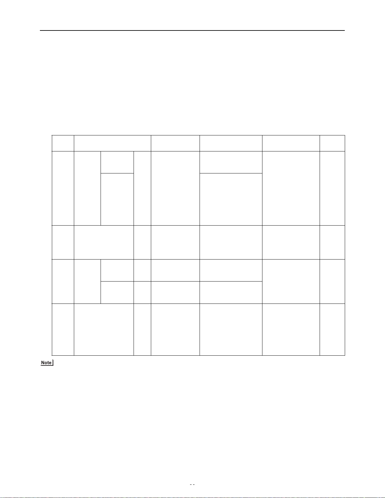
[ II Restrictions ]
(4) Wiring method
1) Indoor/outdoor transmission line
Same as [5] 1.
Shielded cable connection
Same as [5] 1.
2) Transmission line for centralized control
Same as [5] 4.
Shielded cable connection
Same as [5] 4.
3) ME remote controller wiring
ME remote controller is connectable anywhere on the in-
door-outdoor transmission line.
(5) Address setting method
Proce-
dures
1 Indoor
Unit or controller
Main unit IC 01 to 50 Assign the smallest ad-
Address setting
unit
Sub unit Assign sequential num-
2 LOSSNAY LC 01 to 50 Assign an arbitrary but
3 ME re-
mote
controller
Main
remote
controller
Sub
RC 101 to 150 Add 100 to the main unit
RC 151 to 200 Add 150 to the main unit
remote
controller
4 Outdoor unit OC
51 to 100 Assign sequential adOS1
OS2
range
When 2 remote controllers are connected to the system
Refer to the section on Switch Setting.
Performing a group operation (including the group
operation of units in different refrigerant circuits).
Refer to the section on Switch Setting.
4) LOSSNAY connection
Same as [5] 4.
5) Switch setting
Address setting is required as follows.
Setting method Notes
To perform a group
dress to the main unit in
the group.
operation of indoor
units that have differ-
ent functions, desig-
bers starting with the address of the main unit in
the same group +1.
(Main unit address +1,
main unit address +2,
nate the indoor unit in
the group with the
greatest number of
functions as the main
unit.
main unit address +3,
etc.)
None of these adunique address to each
of these units after assigning an address to all
dresses may overlap
any of the indoor unit
addresses.
indoor units.
It is not necessary to
address in the group
set the 100s digit.
To set the address
to 200, set the rota-
address in the group
ry switches to 00.
To set the address to
dress to the outdoor
units in the same refrig-
100, set the rotary
switches to 50.
erant circuit. The outdoor units are
automatically designated as OC, OS1, and
OS2. (Note)
Factory
setting
00
00
101
00
The outdoor units in the same refrigerant circuit are automatically designated as OC, OS1, and OS2.
The outdoor units are designated as OC, OS1, and OS2 in the order of capacity from large to small (if two or more units have
the same capacity, in the order of address from small to large).
HWE09120 GB
39- 39 -
Page 49
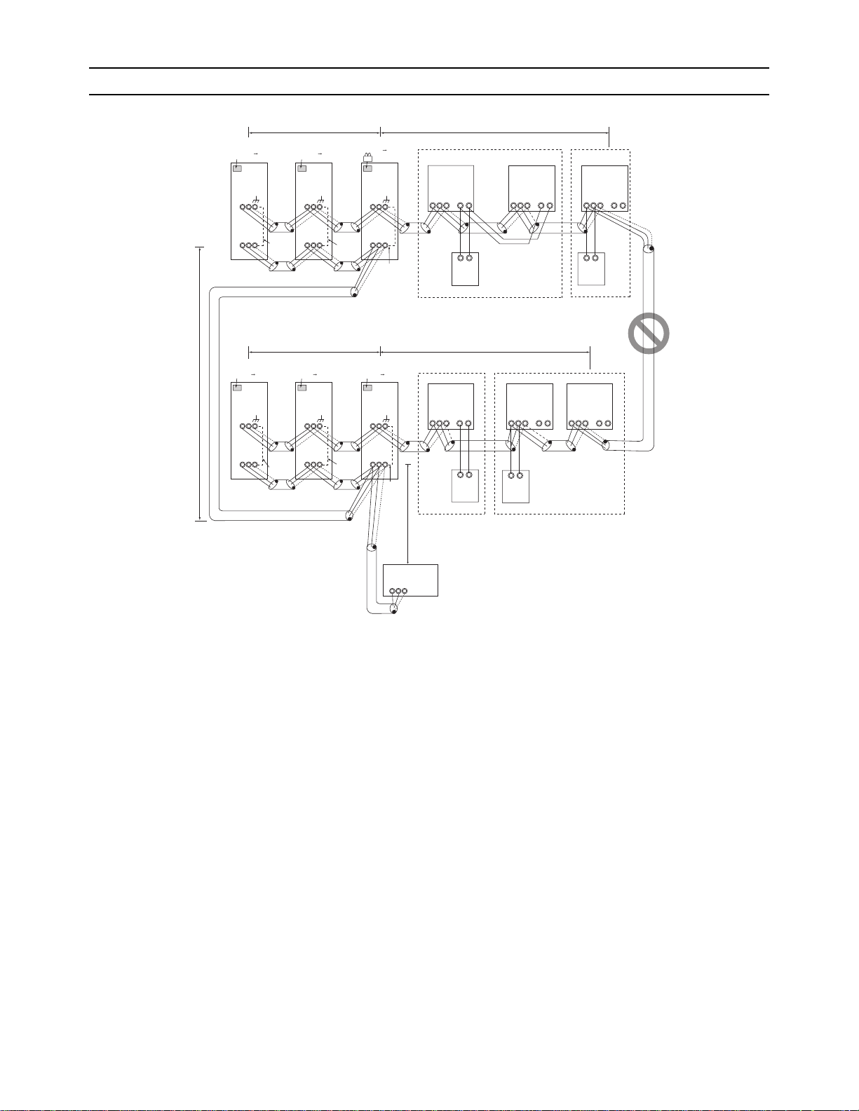
[ II Restrictions ]
[7] An Example of a System to which both MA Remote Controller and ME Remote Controller are connected
(1) Sample control wiring
Leave the male
connector on
CN41 as it is.
SW2-1 OFF ON
TB3
M1 M2 M1 M2 M1 M2
L11 L12
Leave the male
connector on
CN41 as it is.
SW2-1 OFF ON
TB3
Move the male connector
from CN41 to CN40.
SW2-1 OFF ON
OC OS1 OS2
51 52 53
TB3
Group
IC
01
TB5 TB
M1 M2
S
1 2
Group
IC
02
15
TB5 TB
M1 M2
15
1 2
S
TB5 TB
M1 M2
06
S
IC
15
1 2
To be left
unconnected
To be left
unconnected
TB7
To be connected
Leave the male
connector on
CN41 as it is.
SW2-1 OFF ON
OC
54
TB3
TB7
S
S
To be left
unconnected
System controller
A B S
L31
TB7
M1 M2 M1 M2 M1 M2
S
Leave the male
connector on
CN41 as it is.
SW2-1 OFF ON
OS2
56
TB3
M1 M2 M1 M2 M1 M2
TB7
S
M1 M2 M1 M2 M1 M2
TB7
To be left
unconnected
To be left
unconnected
S
L21 L22
Leave the male
connector on
CN41 as it is.
SW2-1 OFF ON
OS1
55
TB3
TB7
S
(2) Cautions
1) Be sure to connect a system controller.
2) ME remote controller and MA remote controller cannot
both be connected to the same group of indoor units.
3) Assign to the indoor units connected to the MA remote
controller addresses that are smaller than those of the indoor units that are connected to the ME remote controller.
4) No more than 2 ME remote controllers can be connected
to a group of indoor units.
5) No more than 2 MA remote controllers can be connected
to a group of indoor units.
6) Do not connect the terminal blocks (TB5) on the indoor
units that are connected to different outdoor units with
each other.
7) Replace the power jumper connector of the control board
from CN41 to CN40 on only one of the outdoor units.
8) Provide an electrical path to ground for the S terminal on
the terminal block for centralized control on only one of
the outdoor units.
9) A transmission booster must be connected to a system
in which the total number of connected indoor units exceeds 20.
10) A transmission booster is required in a system to which
more than 16 indoor including one or more indoor units
of the 72 model or above are connected.
11) When a power supply unit is connected to the transmission line for centralized control, leave the power jumper
connector on CN41 as it is (factory setting).
L32
Note1
TB5
M1 M2
S
IC
A B
MA
Group Group
IC
04 03
15
TB
1 2
A B
MA
TB5 TB
M1 M2
S
1 2
A B
104
RC
Note1 When only the LM adapter is connected,
leave SW2-1 to OFF (as it is).
Note2 LM adapters require the power supply
capacity of single-phase AC 208/230V.
A B
106
RC
IC
05
15
TB5 TB
M1 M2
S
15
1 2
(3) Maximum allowable length
1) Indoor/outdoor transmission line
Same as [5] 3.
2) Transmission line for centralized control
Same as [5] 4.
3) MA remote controller wiring
Same as [5] 1.
4) M-NET remote controller wiring
Same as [5] 1.
5) Maximum line distance via outdoor unit
(1.25 mm
2
[AWG16] min. )
Same as [5] 4.
- 40 -
GBHWE09120
Page 50
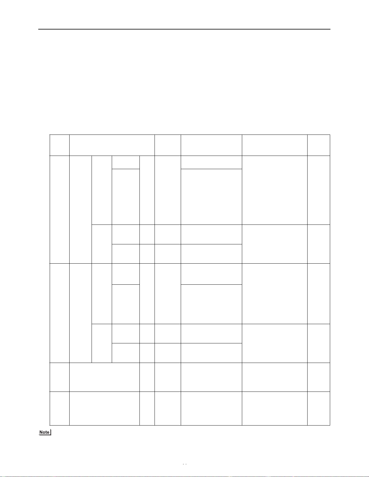
[ II Restrictions ]
(4) Wiring method
1) Indoor/outdoor transmission line
Same as [5] 3.
Shielded cable connection
Same as [5] 1.
2) Transmission line for centralized control
Same as [5] 4.
Shielded cable connection
Same as [5] 4.
3) MA remote controller wiring
Same as [5] 1.
When 2 remote controllers are connected to the system
(5) Address setting method
Proce-
dures
1 Opera-
tion
with the
MA re-
Unit or controller
In-
Main unit IC 01 to 50
door
unit
Sub unit
mote
controller
MA
remote
controller
Main re-
mote con-
troller
Sub
remote
MA No
MA Sub
controller
2 Opera-
tion
with the
ME remote
Indoor
unit
Main unit IC 01 to 50 Assign the smallest ad-
Sub unit
controller
ME remote
controller
Main re-
mote con-
troller
Sub
RC 101 to
RC 151 to
remote
controller
3 LOSSNAY LC 01 to 50
4 Outdoor unit OC
OS1
OS2
Address
setting
range
settings
required.
remote
controller
150
200
51 to 100
Same as [5] 1.
Group operation of indoor units
Same as [5] 1.
4) M-NET remote controller wiring
Same as [5] 1.
When 2 remote controllers are connected to the system
Same as [5] 1.
Group operation of indoor units
Same as [5] 1.
5) LOSSNAY connection
Same as [5] 4.
6) Switch setting
Address setting is required as follows.
Setting method Notes
Assign the smallest address
to the main unit in the group.
Assign sequential numbers starting with the address of the main unit in
the same group +1. (Main
unit address +1, main unit
address +2, main unit address +3, etc.)
-
Settings to be made according to the remote controller function selection
dress to the main unit in
the group.
Assign sequential numbers starting with the address of the main unit in
the same group +1. (Main
unit address +1, main unit
address +2, main unit address +3, etc.)
Add 100 to the main unit
address in the group.
Add 150 to the main unit
Assign an address smaller
than that of the indoor unit
that is connected to the ME
remote controller.
Enter the same indoor unit
group settings on the system
controller as the ones that
were entered on the MA remote controller.
To perform a group operation
of indoor units that have different functions, designate
the indoor unit in the group
with the greatest number of
functions as the main unit.
Enter the indoor unit group
settings on the system controller (MELANS).
Assign an address larger than
those of the indoor units that
are connected to the MA remote controller.
To perform a group operation
of indoor units that have different functions, designate
the indoor unit in the group
with the greatest number of
functions as the main unit.
It is not necessary to set
the 100s digit.
To set the address to 200,
set the rotary switches to
00.
address in the group.
Assign an arbitrary but
unique address to each of
these units after assigning
an address to all indoor
units.
Assign sequential address
to the outdoor units in the
same refrigerantcircuit.
The outdoor units are automatically designated as
OC, OS1, and OS2. (Note)
None of these addresses
may overlap any of the indoor unit addresses.
To set the address to 100,
set the rotary switches to 50.
Factory
setting
00
Main
00
101
00
00
The outdoor units in the same refrigerant circuit are automatically designated as OC, OS1, and OS2.
The outdoor units are designated as OC, OS1, and OS2 in the order of capacity from large to small (if two or more units have
the same capacity, in the order of address from small to large).
HWE09120 GB
41- 41 -
Page 51
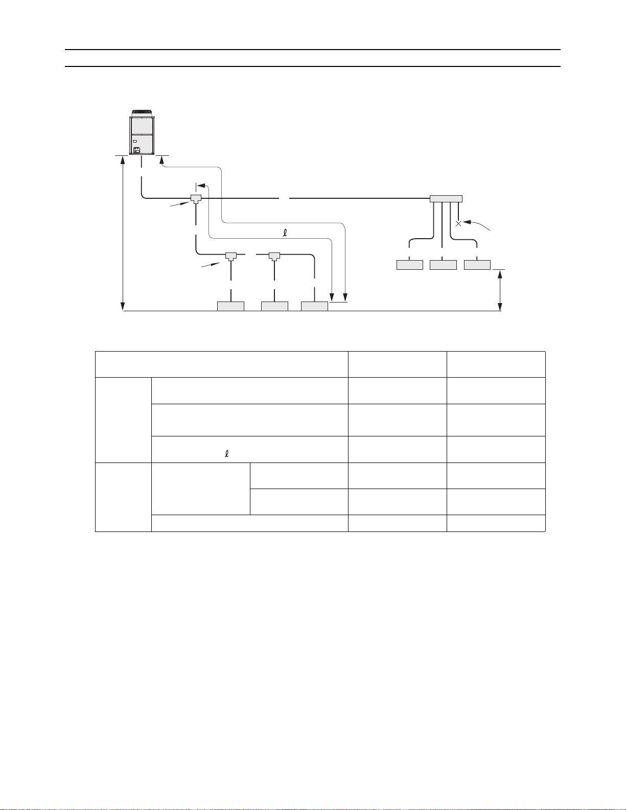
[ II Restrictions ]
[8] Restrictions on Pipe Length
(1) End branching
P72 - P144 models
Outdoor unit
A
D
First branch
(Branch joint)
B
Branch joint
(Outdoor unit above indoor unit)
(Outdoor unit below indoor unit)
'
H
H
C
a
Indoor Indoor Indoor
1
L
d
Indoor Indoor Indoor
b
2
c
3
4
Operation Pipe sections
Length Total pipe length A+B+C+D
+a+b+c+d+e+f
Height
difference
Total pipe length (L) from the outdoor unit to the
farthest indoor unit
Total pipe length from the first branch to the farthest indoor unit ( )
Between indoor and
outdoor units
Outdoor unit above indoor unit
Outdoor unit below in-
A+B+C+c or
A+D+f
B+C+c or
D+f
H 50 [164] or less
H' 40 [131] or less
door unit
Between indoor units h 15 [49] or less
Branch header
cap
e
5
f
6
h
Allowable length of
pipes
1000 [3280] or less
165 [541] or less
(Equivalent length 190
[623] or less)
40 [131] or less
Unit: m [ft]
HWE09120 GB
- 42 -
Page 52
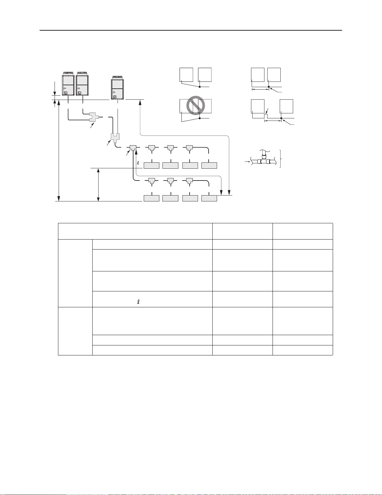
[ II Restrictions ]
P168 - P360 models
The figure shows a system with three outdoor units. (P312-P360 models)
Note1 Install the pipe that connects the branch pipe and the outdoor units in
the way that it has a downward inclination toward the branch pipe.
Provide a trap on the pipe (gas pipe only) within 2 m from the
joint pipe if the total length of the pipe that connects the joint
pipe and the outdoor unit exceeds 2 m.
h2
B D A
C
Second gas refrigerant distributor
Second liquid refrigerant distributor
First liquid refrigerant distributor
First gas refrigerant distributor
H
First branch
h1
Downward inclination
Upward inclination
L
To indoor unit
To indoor unit
(Note)
E F G I
a
Indoor Indoor Indoor Indoor
1
J K M
e
Indoor Indoor Indoor Indoor
5
c
b
d
E
3
2
g
f
6
4
i
7
8
Note : "Total sum of downstream unit model numbers"
in the table is the sum of the model numbers
of the units after point E in the figure.
Operation Pipe sections
2m [6ft]
2m [6ft] Max.
To indoor unit
Joint pipe
Trap
(gas pipe
only)
To downstream units
Allowable length of
To indoor unit
Joint pipe
pipes
Length Between outdoor units A+B+C+D 10 [32] or less
Total pipe length A+B+C+D+E+F+G+I+J
1000 [3280] or less
+K+M+a+b+c+d+e+f+g
+i
Total pipe length (L) from the outdoor unit to the
farthest indoor unit
Total pipe length from the first branch to the far-
A(B)+C+E+J+K+M+i
F+G+I+d or J+K+M+i 40 [131] or less
165 [541] or less
(Equivalent length 190
[623] or less)
thest indoor unit ( )
Height
difference
Between indoor and outdoor units H 50 [164] or less
(40 [131] or below if
outdoor unit is below in-
door unit)
Between indoor units h1 15 [49] or less
Between outdoor units h2 0.1[0.3] or less
Unit: m [ft]
HWE09120 GB
- 43 -
Page 53

[ II Restrictions ]
1. Refrigerant pipe size
(1) Diameter of the refrigerant pipe between the outdoor unit and the first branch (outdoor unit pipe size)
Outdoor unit set name
Liquid pipe size (mm) [inch] Gas pipe size (mm) [inch]
(total capacity)
72 model ø9.52 [3/8"] ø19.05 [3/4"]
96 model ø9.52 [3/8"]
120 model ø9.52 [3/8"]
*1
*2
ø22.2 [7/8"]
ø22.2 [7/8"]
144 model ø12.7 [1/2"] ø28.58 [1-1/8"]
168 model ø15.88 [5/8"] ø28.58 [1-1/8"]
192 model ø15.88 [5/8"] ø28.58 [1-1/8"]
216 model ø15.88 [5/8"] ø28.58 [1-1/8"]
240 model ø15.88 [5/8"] ø28.58 [1-1/8"]
264 - 312 model ø19.05 [3/4"] ø34.93 [1-3/8"]
336 - 360 model ø19.05 [3/4"] ø41.28 [1-5/8"]
*1. Use ø12.7 [1/2"] pipes if the piping length exceeds 90 m [295 ft].
*2. Use ø12.7 [1/2"] pipes if the piping length exceeds 40 m [131 ft].
(2) Size of the refrigerant pipe between the first branch and the indoor unit (indoor unit pipe size)
model Pipe diameter (mm) [inch]
06 - 15 models Liquid pipe ø6.35 [1/4"]
Gas pipe ø12.7 [1/2"]
18 - 54 models Liquid pipe ø9.52 [3/8"]
Gas pipe ø15.88 [5/8"]
72 model Liquid pipe ø9.52 [3/8"]
Gas pipe ø19.05 [3/4"]
96 model Liquid pipe ø9.52 [3/8"]
Gas pipe ø22.2 [7/8"]
(3) Size of the refrigerant pipe between the branches for connection to indoor units
Total capacity of the
Liquid pipe size (mm) [inch] Gas pipe size (mm) [inch]
downstream units
- 54 ø9.52 [3/8"] ø15.88 [5/8"]
P55 - P72 ø9.52 [3/8"] ø19.05 [3/4"]
P72 - P108 ø9.52 [3/8"] ø22.2 [7/8"]
P109 - P144 ø12.7 [1/2"] ø28.58 [1-1/8"]
P145 - P240 ø15.88 [5/8"] ø28.58 [1-1/8"]
P241 - P308 ø19.05 [3/4"] ø34.93 [1-3/8"]
P309 - ø19.05 [3/4"] ø41.28 [1-5/8"]
HWE09120 GB
- 44 -
Page 54
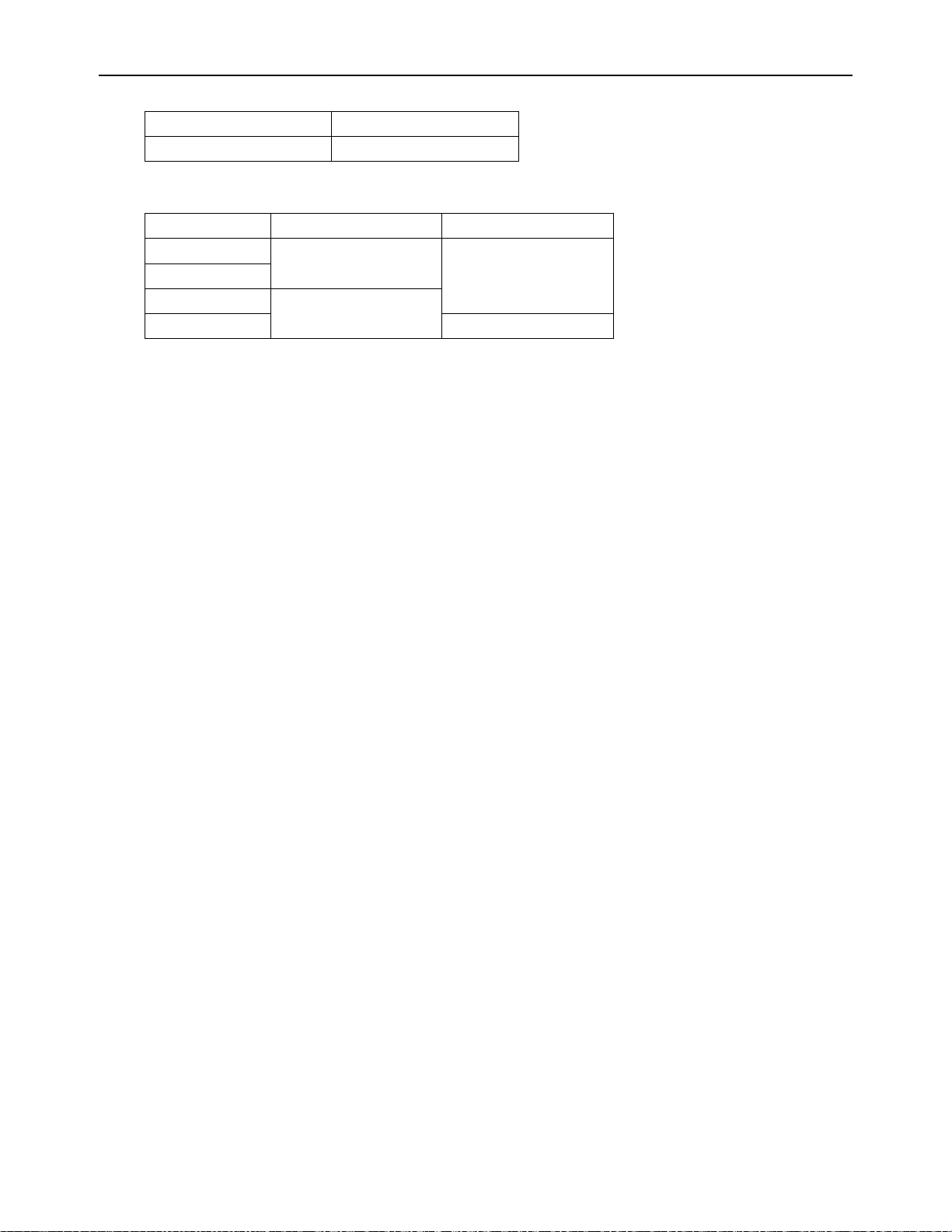
[ II Restrictions ]
(4) Size of the refrigerant pipe between the first distributor and the second distributor
Liquid pipe size (mm) [inch] Gas pipe size (mm) [inch]
ø19.05 [3/4"] ø34.93 [1-3/8"]
(5) Size of the refrigerant pipe between the first distributor or the second distributor and outdoor units
Liquid pipe size (mm) [inch] Gas pipe size (mm) [inch]
72 model ø9.52 [3/8"] ø22.2 [7/8"]
96 model
120 model ø12.7 [1/2"]
144 model ø28.58 [1-1/8"]
* Only applicable to the 144 model and below
HWE09120 GB
- 45 -
Page 55

[ II Restrictions ]
- 46 -
GBHWE09120
Page 56

III
Outdoor Unit Components
[1] Outdoor Unit Components and Refrigerant Circuit .......................................................... 49
[2] Control Box of the Outdoor Unit....................................................................................... 53
[3] Outdoor Unit Circuit Board............................................................................................... 56
HWE09120 GB
- 47 -
Page 57

- 48 -
Page 58

[ III Outdoor Unit Components ]
Fan
Control Control
Box
Control
Box
Fan guard
Fin guard
Front panel
Heat exchangerHeat exchangerHeat exchanger
III Outdoor Unit Components
[1] Outdoor Unit Components and Refrigerant Circuit
1. Front view of a outdoor unit
(1) PUHY-P72, P96TJMU-A
PUHY-P72, P96YJMU-A
HWE09120 GB
- 49 -
Page 59

[ III Outdoor Unit Components ]
Fan
Control Control
BoxBox
Control
box
Fan guard
Fin guard
Front panel
Heat exchanger
Contactor
box
Contactor
box
Transformer box
(YJMU-A only)
Transformer box
(YJMU-A only)
(2) PUHY-P120, P144TJMU-A
PUHY-P120, P144YJMU-A
HWE09120 GB
- 50 -
Page 60

[ III Outdoor Unit Components ]
High-pressure sensor(63HS1)
High-pressure switch(63H1)
Accumulator
Transformer box
(YJMU-A only)
Compressor cover
Compressor
Oil separator
Solenoid valve (SV1a)Solenoid valve (SV9)
Gas-side valve
Liquid-side valve
Linear expansion valve
(LEV2)
Solenoid valve(SV5b)
Linear expansion valve
(LEV1)
Subcool coil
High-pressure check joint
Low-pressure check joint
4-way valve(21S4a)
4-way valve(21S4b)
Check valve
Low-pressure sensor(63LS)
Accumulator
Transformer box
(YJMU-A only)
Compressor cover
Compressor
Oil separator
Solenoid valve (SV1a)
Solenoid valve
(SV9)Gas-side valveLiquid-side valve
Linear expansion valve
(LEV2)
Solenoid valve(SV5b)
Linear expansion valve
(LEV1)
Subcool coil
High-pressure
check joint
Low-pressure
check joint
4-way valve(21S4a)
4-way valve(21S4b)
Check valve
Low-pressure sensor
(63LS)
High-pressure sensor(63HS1)High-pressure switch(63H1)
2. Refrigerant circuit
(1) PUHY-P72TJMU-A
PUHY-P72YJMU-A
(2) PUHY-P96TJMU-A
PUHY-P96YJMU-A
HWE09120 GB
- 51 -
Page 61

[ III Outdoor Unit Components ]
High-pressure sensor(63HS1)
Accumulator
Compressor cover
Compressor
Oil separator
Solenoid valve
(SV1a)
Solenoid valve
(SV9)
Gas-side valve
Liquid-side valve
Linear expansion valve
(LEV2)
Solenoid valve(SV5b)
Linear expansion
valve(LEV1)
Subcool coil
High-pressure check joint
Low-pressure check joint
4-way valve(21S4a)
4-way valve(21S4b)
Check valve
Low-pressure sensor(63LS)
High-pressure switch
(63H1)
4-way valve(21S4c)
Solenoid valve(SV5c)
(3) PUHY-P120, P144TJMU-A
PUHY-P120, P144YJMU-A
The YJMU model has a transformer box.
HWE09120 GB
- 52 -
Page 62

[ III Outdoor Unit Components ]
<HIGH VOLTAGE WARNING>
Control box houses high-voltage parts.
When opening or closing the front panel of the control box, do not let it come into contact with any of
the internal components.
Before inspecting the inside of the control box, turn off the power, keep the unit off for at least 10 minutes,
and Check that the voltage across terminals FT-P and FT-N (YJMU) on the INV board or the voltage at
both ends of the main capacitor (C1) (TJMU) is 20VDC or below.
(It takes about 10 minutes to discharge electricity after the power supply is turned off.)
Electromagnetic relay(72C)
DC reactor (DCL)
Fan board
Rush current
protection resistor
(R1) Note.2
Noise filter
Note.2
Terminal block for
power supply
(TB1)
Note.1
Ground terminal
Smoothing capacitor(C1)
INV board
Terminal block for transmission line
(TB3, TB7)
M-NET board
Control board
[2] Control Box of the Outdoor Unit
1. PUHY-P72, P96TJMU-A
1) Exercise caution not to damage the bottom and the front panel of the control box. Damage to these parts affect the waterproof and dust proof properties of the control box and may result in damage to its internal components.
2) Faston terminals have a locking function. Make sure the cable heads are securely locked in place. Press the tab on the terminals to remove them.
HWE09120 GB
- 53 -
Page 63

[ III Outdoor Unit Components ]
Current sensor
(ACCT3)
Note.2
Fan board
INV board Control board
DC reactor (DCL)
Diode stack
Noise filter
Current sensor
(DCCT1)
Terminal block for
power supply
(TB1)
Ground terminal
Smoothing capacitor(C1)
Note.1
Current sensor
(ACCT2)
Current sensor
(ACCT1)
IPM
Terminal block for transmission line
(TB3, TB7)
M-NET board
Electromagnetic relay
(72C)
INV board
Terminal block for
power supply
(TB1)
Noise filter
DC reactor (DCL)
Electromagnetic relay(72C)
Capacitor(C100)
Rush current protection resistor
(R1,R5) Note.2
Fan board
Control board
M-NET board
Terminal block for transmission line
(TB3, TB7)
Note.1
Fuse(F4)
Fuse(F5)
Ground
terminal
2. PUHY-P96, P120, P144TJMU-A
3. PUHY-P72, P96, P120, P144YJMU-A
1) Exercise caution not to damage the bottom and the front panel of the control box. Damage to these parts affect the water-
2) Faston terminals have a locking function. Make sure the cable heads are securely locked in place. Press the tab on the ter-
HWE09120 GB
proof and dust proof properties of the control box and may result in damage to its internal components.
minals to remove them.
- 54 -
Page 64

[ III Outdoor Unit Components ]
4. Transformer Box (PUHY-P72, P96, P120, P144YJMU-A)
Transformer
(T03)
Transformer
(T02)
HWE09120 GB
- 55 -
Page 65

[ III Outdoor Unit Components ]
CN332
Output 18VDC
GND
(Fan board)
LED2
Lit during normal
CPU operation
Serial communication signal input
GND
INV board
Output 17VDC
CN801
Pressure switch
connection
CN4
GND
Serial communication signal output
LEV
driving output
LED1
Service LED
SWU1,2
Address switch
SW1-5
Dip
switch
Sensor
input
CNVCC2
Output 12VDC
Output 5VDC
GND
CNIT
Output 12VDC
GND
Output 5VDC
Power supply detection input
Power supply ON/OFF signal output
CNS2
Transmission line input/output
for centralized control system (30VDC)
CN41
Power supply for
centralized control OFF
CN40
Power supply for
centralized control ON
CN102
Indoor/outdoor transmission line input/output (30VDC)
Power supply input for centralized control system (30VDC)
External signal input (contact input)
F01
Fuse
250V AC/3.15A
CNAC
L1
L2
Actuator
driving output
Output 12VDC
Compressor
ON/OFF output
Error output
CN51
CNAC2
L1
L2
CNDC
Bus voltage input
P
N
CN2
CN72
72C driving output
(YJMU)
CN505
72C driving output
(TJMU)
LED3
Lit when powered
[3] Outdoor Unit Circuit Board
1. Outdoor unit control board
HWE09120 GB
- 56 -
Page 66

[ III Outdoor Unit Components ]
2. M-NET board
(TJMU only)
F01
250V
3.15A
Grounding
CN03(TJMU only)
Bus voltage input
P
N
CN04
Bus voltage input
(YJMU only)
Bus voltage output
(TJMU only)
P
N
Grounding
Grounding
CN102
Power supply output for centralized
control system (30VDC)
Indoor/outdoor transmission line
input/output (30VDC)
Ground terminal for
TB3
Indoor/outdoor transmission block
transmission line
CNS2
Transmission line
input/output for
centralized control
system (30VDC)
TB7
Terminal block for
transmission line for
centralized control
CNIT
Input 12VDC
GND
Input 5VDC
Power supply
detection output
Power supply
ON/OFF signal input
LED1
Power supply for
indoor
transmission line
TP1,2
Check pins for
indoor/outdoor
transmission line
HWE09120 GB
- 57 -
Page 67
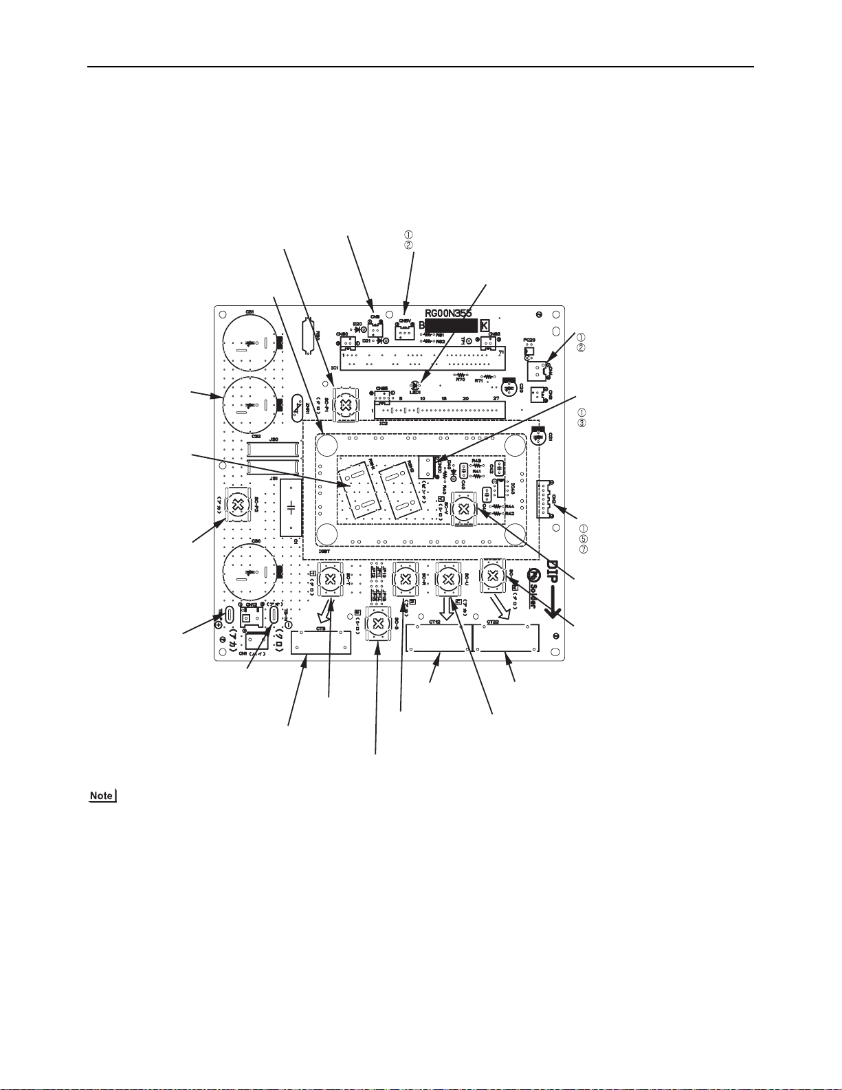
[ III Outdoor Unit Components ]
3. INV board
(1) PUHY-P72TJMU-A
SC-P1
Rectifier diode output (P)
C30,31,32
Smoothing capacitor
RSH1,2
Overcurrent detection
resistor
CN6
Open: No-load operation setting
Short-circuited: Normal setting
IGBT
(Rear)
CN5V
GND
Output 5VDC
LED1
Lit: Inverter in normal operation
Blink: Inverter error
CN4
GND
Serial communication signal output
CNDC
Bus voltage output
P
N
(Fan Board)
CN2
S
erial communication signal output
SC-P2
Bus voltage Input(
TB-P(Note)
Bus voltage output(P
P)
)
TB-N(Note)
Bus voltage output
(N)
SC-T
Input(L3)
CT3
Current sensor(
L3)
SC-S
Input(L2)
CT12
Current sensor
SC-R
Input(L1)
CT22
Current sensor
(U)
SC-U
Inverter output(U)
GND
Input 17VDC
SC-V
Inverter output(V)
SC-W
Inverter output(W)
(W)
Faston terminals have a locking function. Make sure the cable heads are securely locked in place. Press the tab on the terminals to remove them.
HWE09120 GB
- 58 -
Page 68
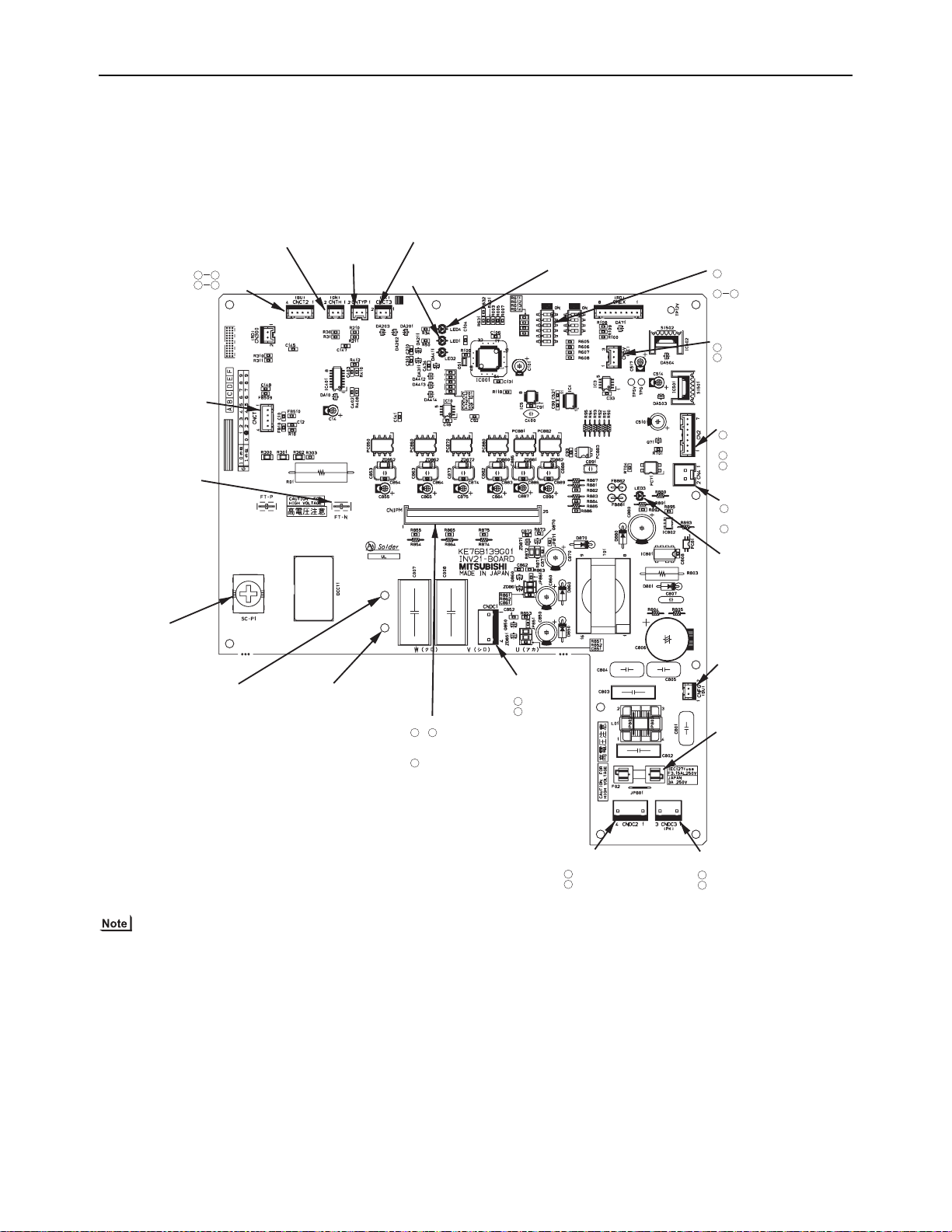
[ III Outdoor Unit Components ]
CNCT2
AC sensor input
ACCT1
ACCT2
CNTH
Thermistor input
(THHS)
CNTYP
Function setting
connector input
(Z26)
CNCT3
AC sensor input
(ACCT3)
LED1
Inverter operation (Lit)/error (Blinking)
SW1
:Fixed to OFF
CN5V
GND
5 VDC output
CN2
Serial communication
signal output
GND
17 VDC input
CN4
GND
(FAN INV board)
Serial communication
signal input
LED3
Charging
CNFG
Functional earth
F02
Fuse
AC250V 3.15A
CNDC3
Bus voltage output
P
N
P
N
CNDC2
Bus voltage input
CNDC1
Bus voltage output
SC-P1
Bus voltage
input/output(P)
IPM-P
Bus voltage output(P)
(IPM input)
IPM-N
Bus voltage input/output(N)
(IPM input)
FT-N(Note)
Bus voltage
output(N)
CNCT
DC sensor input
(DCCT1)
LED4
Lit during normal CPU operation
1 2
34
2
1
5
7
1
2
1
1
3
6
ON:No-load operation setting
OFF:Normal setting
P
N
1
CNIPM
~
Power and signal outputs for
driving the IPM
IPM error signal input
(IPM output)
1
24
25
4
1
4
1
3
(2) PUHY-P96, P120, P144TJMU-A
Faston terminals have a locking function. Make sure the cable heads are securely locked in place. Press the tab on the terminals to remove them.
HWE09120 GB
- 59 -
Page 69
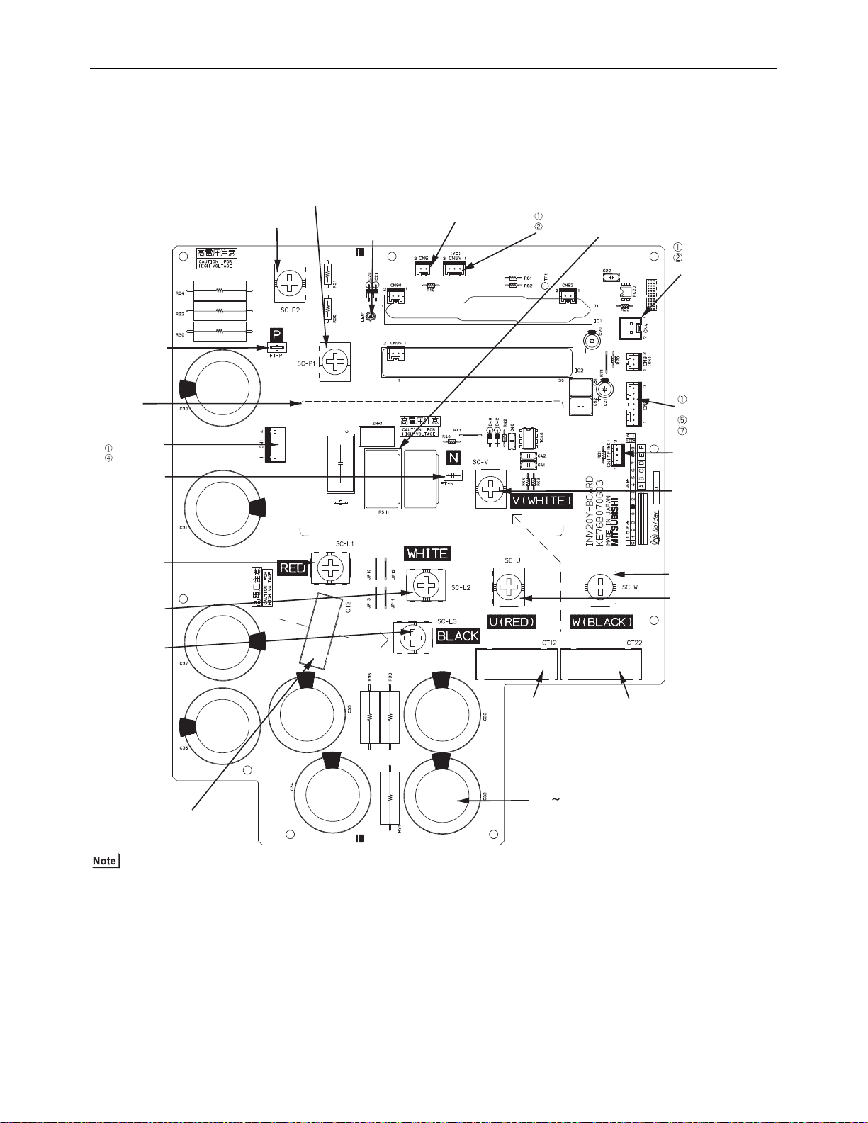
[ III Outdoor Unit Components ]
SC-L1
Input(L1)
SC-L2
Input(L2)
SC-L3
Input(L3)
IGBT
(Rear)
Bus voltage check
terminal (P)
Note
Bus voltage check
terminal (N)
Note 1
SC-P2
Bus voltage Input(P)
SC-P1
Rectifier diode output (P)
LED1
Lit: Inverter in normal operation
Blink: Inverter error
CN6
Open: No-load operation setting
Short-circuited: Normal setting
CN5V
GND
5VDC output
RSH1
Overcurrent detection
resistor
CN4
GND
(Fan Board)
Serial communication
signal output
CN2
S
erial communication
signal output
GND
17VDC input
SC-V
Inverter output(V)
CNTYP Inverter
board type
SC-W
Inverter output(W)
SC-U
Inverter output(U)
CT22
Current sensor(W)
CT12
Current sensor(U)
C30 C37
Smoothing capacitor
CN1
Bus voltage output
N
P
CT3
Current sensor(L3)
(3) PUHY-P72, P96, P120, P144YJMU-A
1) Before inspecting the inside of the control box, turn off the power, keep the unit off for at least 10 minutes, and confirm that
the voltage between FT-P and FT-N on INV Board has dropped to DC20V or less.
(It takes about 10 minutes to discharge electricity after the power supply is turned off.)
HWE09120 GB
- 60 -
Page 70
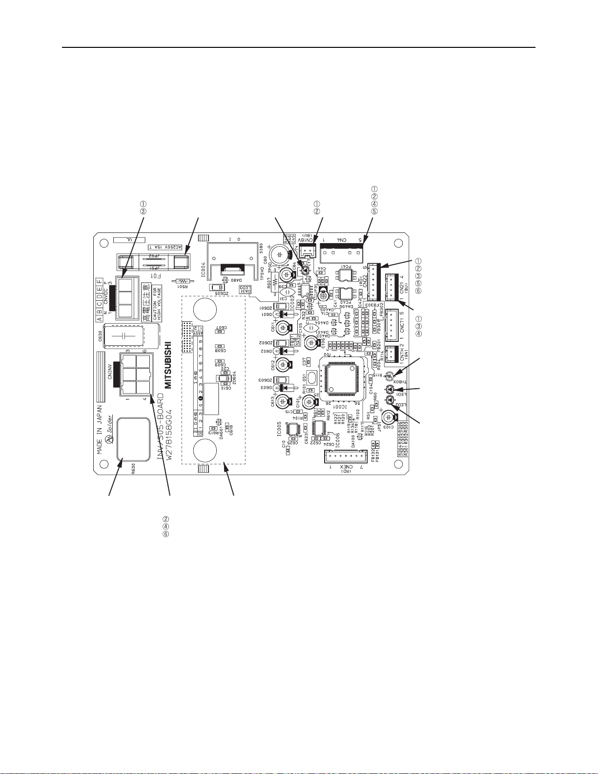
[ III Outdoor Unit Components ]
CNVDC
Bus voltage input
N
P
F01
Fuse
250VAC 15A
LED3
Lit during normal
CPU operation
CN18V
Input 18VDC
GND
CN4
GND
Serial communication signal output
GND(Control board)
Serial communication signal output
CN22
GND(INV board)
Input 5VDC
Serial communication signal input
GND(INV board)
Input 17VDC
CN21
Serial communication signal output
GND(INV board)
Input 17VDC
THBOX
Thermistor
(Control box internal temperature
detection)
LED1
Inverter in normal operation
LED2
Inverter error
DIP IPM(Rear)
CNINV
Inverter output
W
V
U
R630
Overcurrent detection
resistor
4. Fan board
(1) PUHY-P72, P96, P120, P144TJMU-A
HWE09120 GB
- 61 -
Page 71
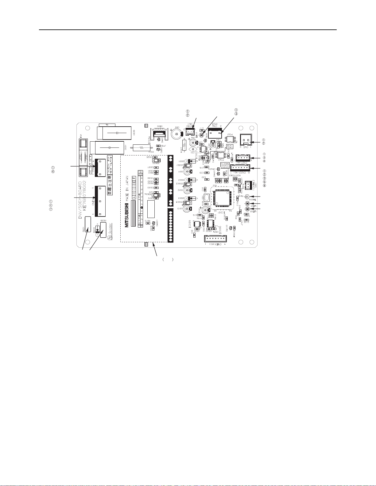
[ III Outdoor Unit Components ]
(2) PUHY-P72, P96, P120, P144YJMU-A
CNVDC
Bus voltage input
N
P
CNINV
Inverter output
W
V
U
R630,R631
Overcurrent detection
resistor
DIP IPM Rear
CN18V
Input 18VDC
GND
LED3
Lit during normal
CPU operation
CN4
GND
Serial communication signal output
CN5
GND(Control board)
Serial communication signal output
CN21
Serial communication signal output
GND(INV board)
Input 17VDC
CN22
GND(INV board)
Input 5VDC
Serial communication signal input
GND(INV board)
Output 17VDC
THBOX
Thermistor
(Control box internal temperature
detection)
LED1
Inverter in normal operation
LED2
Inverter error
HWE09120 GB
- 62 -
Page 72
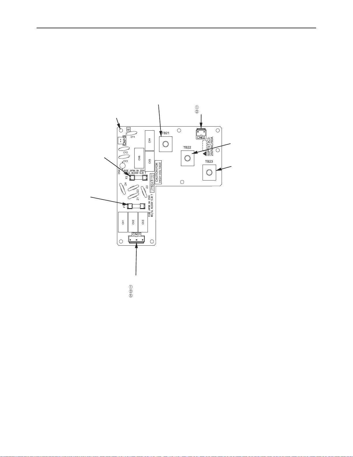
[ III Outdoor Unit Components ]
Grounding
TB21
Input/output(L1)
CN02
Output
L1
L2
TB22
Input/output(L2)
TB23
Input/output(L3)
CN01
Input
L3
L2
L1
F1
Fuse
250VAC 6.3A
F2
Fuse
250VAC 6.3A
5. Noise Filter
(1) PUHY-P72TJMU-A
HWE09120 GB
- 63 -
Page 73

[ III Outdoor Unit Components ]
Grounding
F3
Fuse
250VAC 6.3A
R1,2
Rush current
protection resistor
TB42
Bus voltage output(N)
TB31
Bus voltage output(P)
CN03
72C drive input
Electromagnetic relay
(72C)
Diode stack rectified voltage
input (Diode stack output)
Output
(Diode stack input)
TB23
Input
(L3)
TB22
Input
(L2)
TB21
Input
(L1)
CN01
Input
L3
L2
L1
F2
Fuse
250VAC 6.3A
F1
Fuse
250VAC 6.3A
CN02
Output
L1
L2
(2) PUHY-P96, P120, P144TJMU-A
HWE09120 GB
- 64 -
Page 74

[ III Outdoor Unit Components ]
CN4
Output
(Rectified L2-L3 current)
P
N
CN5
Output
(Rectified L2-L3 current)
P
N
TB21
Input/output(L1)
TB22
Input/output(L2)
TB23
Input/output(L3)
CN1B
Input
L3
L2
CN1A
Input
L1
Grounding
F1,F2,F3,F4
Fuse
250VAC 6.3A
CN6
Input
L2
L3
Grounding
CN2
Surge absorber circuit
Surge absorber circuit
Short circuit
Short circuit
(3) PUHY-P72, P96, P120, P144YJMU-A
HWE09120 GB
- 65 -
Page 75

[ III Outdoor Unit Components ]
- 66 -
GBHWE09120
Page 76

IV
Remote Controller
[1] Functions and Specifications of MA and ME Remote Controllers ................................... 69
[2] Group Settings and Interlock Settings via the ME Remote Controller .............................70
[3] Interlock Settings via the MA Remote Controller ............................................................. 74
[4] Using the built-in Temperature Sensor on the Remote Controller ................................... 75
HWE09120 GB
- 67 -
Page 77

- 68 -
Page 78

[ IV Remote Controller ]
MA remote controller
Outdoor unit
Indoor unit
M-NET transmission line
(indoor/outdoor transmission line)
groupgroup
ME remote controller
Outdoor unit
Indoor unit
M-NET transmission line
(indoor/outdoor transmission line)
groupgroup
IV Remote Controller
[1] Functions and Specifications of MA and ME Remote Controllers
There are two types of remote controllers: ME remote controller, which is connected on the indoor-outdoor transmission
line, and MA remote controller, which is connected to each indoor unit.
1. Comparison of functions and specifications between MA and ME remote controllers
Functions/specifications MA remote controller
*1*2
ME remote controller
*2
Remote controller address settings Not required Required
Indoor/outdoor unit address settings
Not required (required only by a system
with one outdoor unit)
*3
Wiring method Non-polarized 2-core cable
Required
Non-polarized 2-core cable
To perform a group operation, daisy-
chain the indoor units using non-polarized 2-core cables.
Remote controller connection Connectable to any indoor unit in the
group
Interlock with the ventilation unit Each indoor unit can individually be in-
terlocked with a ventilation unit. (Set up
via remote controller in the group.)
Changes to be made upon grouping change
MA remote controller wiring between indoor units requires rewiring.
Connectable anywhere on the indoor-outdoor transmission line
Each indoor unit can individually be interlocked with a ventilation unit. (Set up via
remote controller.)
Either the indoor unit address and remote
controller address must both be changed,
or the registration information must be
changed via MELANS.
*1. MA remote controller refers to MA remote controller (PAR-20MAU, PAR-21MAA), MA simple remote controller, and wire-
less remote controller.
*2. Either the MA remote controller or the ME remote controller can be connected when a group operation of units in a sys-
tem with multiple outdoor units is conducted or when a system controller is connected.
*3. Depending on the system configuration, some systems with one outdoor unit may require address settings.
2. Remote controller selection criteria
MA remote controller and ME remote controller have different functions and characteristics. Choose the one that better suits
the requirements of a given system. Use the following criteria as a reference.
MA remote controller
*1*2
There is little likelihood of system expansion and group-
ing changes.
Grouping (floor plan) has been set at the time of instal-
lation.
ME remote controller
There is a likelihood of centralized installation of remote
controllers, system expansion, and grouping changes.
Grouping (floor plan) has not been set at the time of in-
stallation.
*1*2
To connect the remote controller directly to the OA pro-
cessing unit.
*1. ME remote controller and MA remote controller cannot both be connected to the same group of indoor units.
*2. A system controller must be connected to a system to which both MA remote controller and ME remote controller are con-
nected.
<System with MA remote controller> <System with ME remote controllers>
HWE09120 GB
- 69 -
Page 79

[ IV Remote Controller ]
<Deletion error>
[Normal display]
(B) Interlock Settings (A) Group Settings
Indoor unit address display window
Indoor unit
address
display window
Interlocked unit
address
display window
Make the following settings to perform a group operation of units that are connected to different outdoor units or to manually set up the
indoor/outdoor unit address.
(A) Group settings...........Registration of the indoor units to be controlled with the remote controller,
and search and deletion of registered information.
(B) Interlock settings........Registration of LOSSNAY units to be interlocked with the indoor units,
and search and deletion of registered information
[Operation Procedures]
(1) Address settings
Register the indoor unit to be controlled with the remote controller.
Bring up either one of the following displays on the remote controller:
The blinking display of HO, which appears when the power is turned on, or the
normal display, which appears when the unit is stopped. The display window must
look like one of the two figures below to proceed to the next step.
1
2
Bring up the Group Setting window.
-Press and hold buttons [FILTER] and [LOUVER]
simultaneously for 2 seconds to bring up the display as
shown below.
3
A
C
D
B
Select the unit address.
-
Select the address of the indoor unit to be registered by pressing
button
[SET TEMP. ( ) or ( )] to advance or go back
through the addresses.
Register the indoor unit whose address appears on the
display.
- Press button [TEST] to register the indoor unit address
whose address appears on the display.
- If registration is successfully completed, unit type will appear
on the display as shown in the figure below.
- If the selected address does not have a corresponding indoor
unit, an error message will appear on the display. Check the
address, and try again.
5
<Successful completion of registration>
Unit type (Indoor unit in this case)
blinks to indicate a registration error.
(Indicates that selected address does not have a
corresponding unit.)
4
To register the addresses for multiple indoor units, repeat
steps and above.
3
4
To search for an address,
go to section (2) Address Search.
Next page.
To search for an address,
go to section (2) Address Search.
Bring up the Interlock Setting window.
-Press button [MODE] to bring up the following display.
Press again to go back to the Group Setting window as shown
under step .
6
G
2
Both the indoor unit address and
interlocked unit address will be
displayed together.
Bring up the address of the indoor unit and the address of the
LOSSNAY to be interlocked on the display.
- Select the address of the indoor unit to be registered by pressing
button [SET TEMP. ( ) or ( )] to advance or go back through
the addresses.
- Select the address of the LOSSNAY unit to be interlocked by
pressing button [TIMER SET ( ) or ( )] to advance or go back
through the interlocked unit addresses.
7
8
C
H
Make the settings to interlock LOSSNAY units with indoor
units.
- Press button [TEST] while both the indoor unit address and
the address of the LOSSNAY units to be interlocked
are displayed to enter the interlock setting.
- Interlock setting can also be made by bringing up the
LOSSNAY address in the indoor unit address display
window and the indoor unit address in the interlocked unit
address display window.
D
(Displayed alternately)
If registration is successfully
completed, the two displays as
shown on the left will appear
alternately.
If the registration fails,
will blink on the display.
(Indicates that the selected
address does not have a
corresponding unit.)
NOTE : Interlock all the indoor units in the group with the
LOSSNAY units; otherwise, the LOSSNAY units will
not operate.
[Blinking display of HO ]
ON/OFF
SET TEMP.
PAR-F27MEA-US
FILTER
CHECK
TEST
CLOCKONOFF
MODE TIMER
FAN SPEED
LOUVER
VENTILATION
AIR DIRECTION
TIMER SET
?
A
F
D
B
H
G
C
E
[2] Group Settings and Interlock Settings via the ME Remote Controller
1. Group settings/interlock settings
HWE09120 GB
- 70 -
Page 80
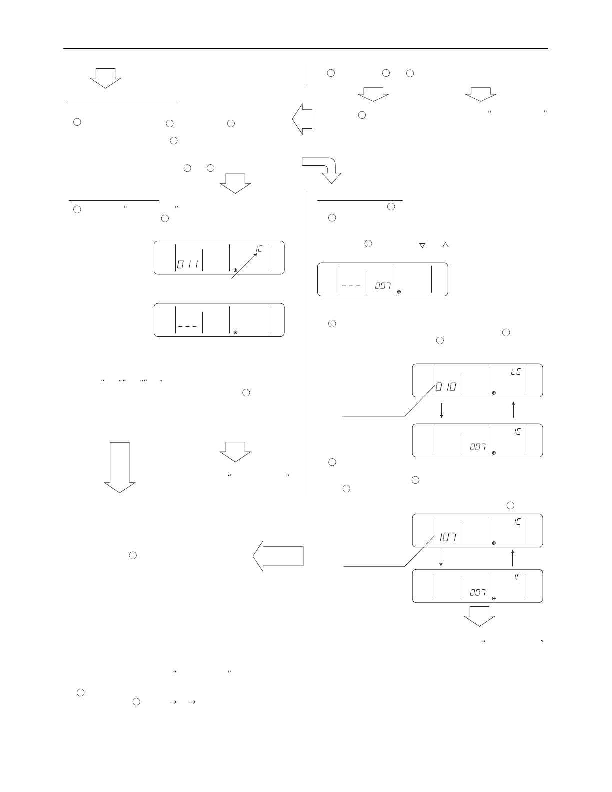
[ IV Remote Controller ]
<Entry found>
<No entries found>
(C) To return to the normal display
When all the group settings and interlock settings are made, take the
following step to go back to the normal display.
Press and hold buttons [FILTER] and [LOUVER]
simultaneously for 2 seconds to go back to the
window as shown in step .
(2) Address search
To search for the address of indoor units that have been entered into
the remote controller, follow steps and .
(A) To search group settings
Unit type
(Indoor unit in this case)
- When only one unit address is registered, the same address
will remain on the display regardless of how many times the
button is pressed.
- When the address of multiple units are registered
(i.e. 011, 012, 013 ), they will be displayed one at a time in
an ascending order with each pressing of button [TIMER ] .
To delete an address, go to
section (3) Address Deletion.
To go back to the normal display,
follow step
(Displayed alternately)
To delete an address,
go to section (3) Address Deletion .
Bring up the address of another registered unit on the
display.
- After completing step , a subsequent pressing of button
[TIMER] will bring up the address of another registered
unit.
(The display method is the same as the one in step .)
Address of an interlocked
LOSSNAY unit
Address of another
interlocked unit
Bring up on the display the address of the LOSSNAY unit
that was interlocked with the indoor unit in step .
- With each pressing of button [TIMER], the address of the
LOSSNAY and indoor unit that is interlocked with it will be
displayed alternately.
LOSSNAY can be searched in the same manner by bringing up
the LOSSNAY address in the Interlocked unit address display window.
(B) Interlock setting search
After performing step , proceed as follows:
Bring up the address of the indoor unit to be searched on
the display.
- Select the address of the indoor unit to be searched by pressing
button [TIMER SET ( ) or ( )] to advance or go back
through the interlocked addresses.
Repeat steps and in the previous page to interlock
all the indoor units in a group with the LOSSNAY unit.
7
8
To go back to the normal display,
follow step
To search for an address,
go to section (2) Address Search.
(3) Address deletion
(Displayed alternately)
10
A
B
1
Bring up the Group Setting window.
- Each pressing of button [TIMER ] will bring up the address of a
registered indoor unit and its unit type on the display.
11
E
1
2
E
10
E
13
13
13
12
14
12
6
E
H
9
10
The addresses of the indoor units that have been entered into the remote controller can be deleted by deleting the group settings.
The interlock settings between units can be deleted by deleting the interlock settings.
Follow the steps in section (2) Address Search to find the address to be deleted and perform deletion with the address being displayed in the
display window. To delete an address, the address must first be bought up on the display.
Delete the registered indoor unit address or the interlock setting between units.
- Press button ? [CLOCK ON OFF] twice while either the indoor unit address or the address of the interlocked unit is displayed on the
display to delete the interlock setting.
F
15
HWE09120 GB
- 71 -
Page 81
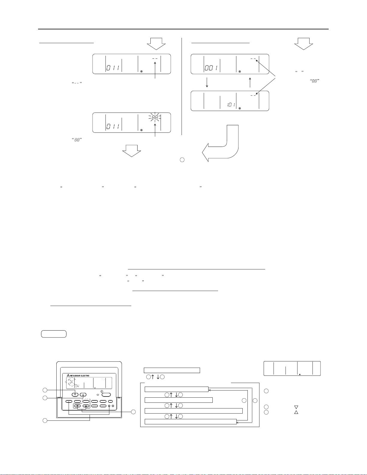
[ IV Remote Controller ]
(A) To delete group settings
(B) To delete interlock settings
<Successful completion of deletion>
will be displayed in the room temperature display window.
- If a transmission error occurs, the selected setting will not be
deleted, and the display will appear as shown below.
In this case, repeat the steps above.
(Displayed alternately)
<Deletion error>
will be displayed in the room temperature display window.
(4) Making (A) Group settings and (B) Interlock settings of a group from any arbitrary remote controller
(A) Group settings and (B) Interlock settings of a group can be made from any arbitrary remote controller.
Refer to (B) Interlock Settings under section 1 Group Settings/Interlock Settings for operation procedures.
Set the address as shown below.
(A) To make group settings
Interlocked unit address display window...Remote controller address
Indoor unit address display window...........The address of the indoor unit to be controlled with the remote controller
(B) To make interlock settings
Interlocked unit address display window...LOSSNAY address
Indoor unit address display window..........The address of the indoor unit to be interlocked with the LOSSNAY
If deletion is successfully
completed, will appear in
the unit type display window.
If the deletion fails, will
appear in the unit type display
window. In this case, repeat the
steps above.
- -
To go back to the normal display, follow step .
10
PAR-F27MEA-US
ON/OFF
FILTER
FUN SPEED
LOUVER
VENTILATION
AIR DIRECTION
CHECK TEST
TIMER SET
MODE TIMER
CLOCK? ON? OFF
SET TEMP.
COOL
AUTO
HEAT
FAN
SPEED
1
3
2
4
In the remote controller function selection mode, the settings for three types of functions can be made or changed as necessary.
3) Narrowed preset temperature range mode
The default temperature ranges are 67°F to 87°F in the cooling/dry mode and 63°F to 83°F in the heating mode.
By changing these ranges (raising the lower limit for the cooling/dry mode and lowering the upper limit for the heating mode), energy can be
saved.
*The settable range varies depending on the unit to be connected.
On the PAR-F27MEA-US model, automatic operation mode cannot be selected while the unit is in the narrowed preset temperature range mode.
Only the lower limit can be set for cooling/dry mode, and upper limit for heating mode.
NOTE
[Function selection mode sequence on the remote controller]
Normal Display (Stopped unit)
1 1
3
2
3
2
3
2
3
2
[Normal display]
Operation mode display selection mode
Room temperature display selection mode
Narrowed preset temperature range mode (cooling/dry mode)
Narrowed preset temperature range mode (heating mode)
CENTRALLY CONTROLLED
DAILY
AUTO OFF
DRY
FAN
REMAINDER
ERROR CODE
CLOCK
SET TEMP.
AUTOONAUTO
OFF
FAN
SPEED
CHECK MODE
FILTER
SENSOR
INSIDE
TEST RUN
LIMIT TEMP.
1Hr.
NOT AVAILABLE
VENTILATION
STAND BY
DEFROST
TIMER
CHECK
1
3
2
: Press and hold the [CHECK] and
[MODE] buttons simultaneously
for two seconds.
: [SET TEMP.
( ) ]
button
: [SET TEMP.
( ) ]
button
2) Room temperature display selection mode (Display or non-display of room temperature)
Although the suction temperature is normally displayed on the remote controller, the setting can be changed so that it will not appear on the
remote controller.
1) Operation mode display selection mode (Display or non-display of COOL/HEAT during automatic operation mode)
When the automatic operation mode is selected, the indoor unit will automatically perform a cooling or heating operation based on the room
temperature. In this case, AUTO COOL or AUTO HEAT will appear on the remote controller display.
This setting can be changed so that only AUTO will appear on the display.
Remote controller function selection mode
2. Remote controller function selection via the ME remote controller
HWE09120 GB
- 72 -
Page 82
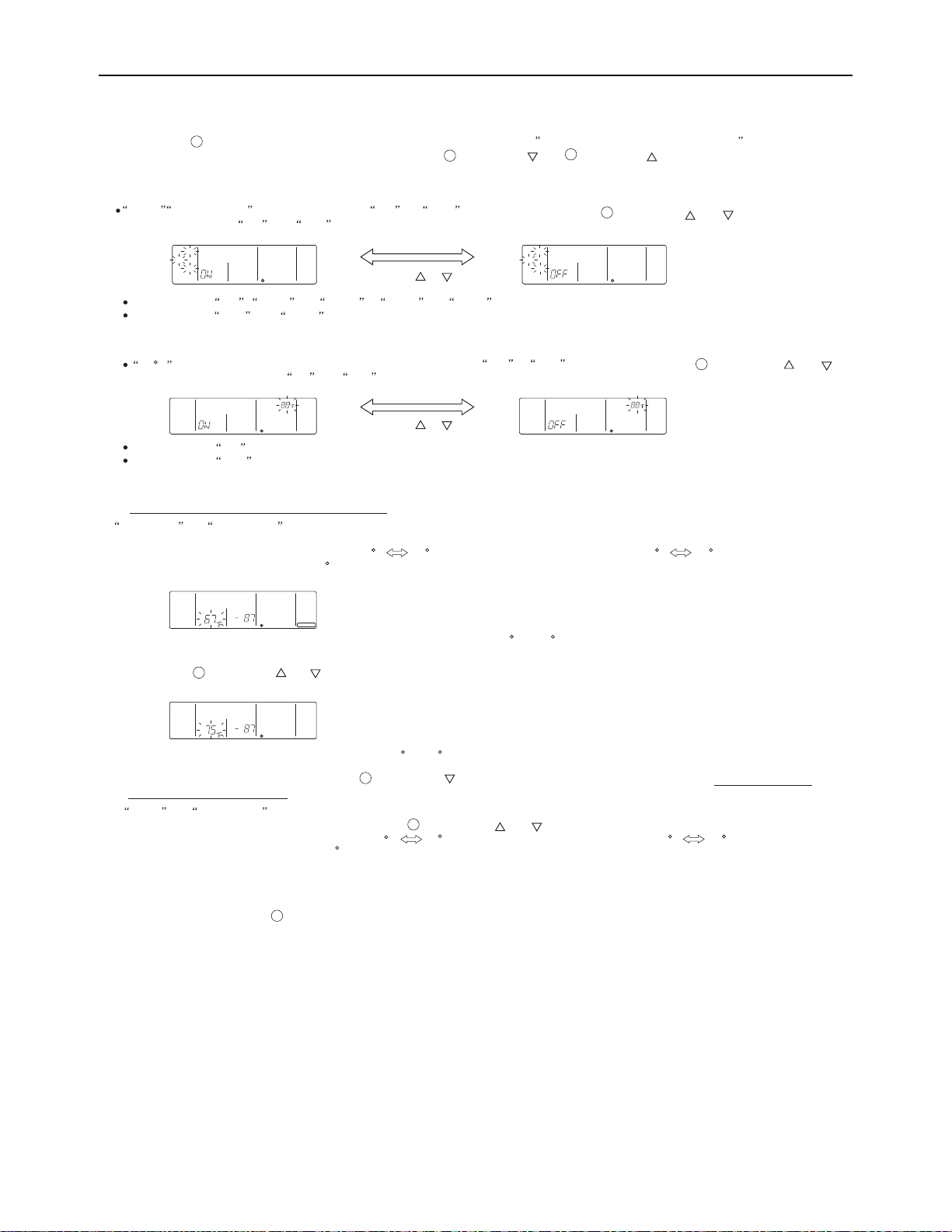
[ IV Remote Controller ]
1Hr.
NOT AVAILABLE
VENTILATION
STAND BY
DEFROST
TIMER
CHECK
[Operation Procedures]
1. Press the [ON/OFF] button on the remote controller to bring the unit to a stop. The display will appear as shown in the previous page (Normal
display).
2. Press buttons [CHECK] and [MODE] simultaneously for 2 seconds to go into the operation mode display selection mode
under the remote controller function selection mode. Press button [SET TEMP. ( )] or [SET TEMP. ( )] to go into the other three modes
under the remote controller function selection mode.
2
3
Operation mode display selection mode (Display or non-display of room temperature on the remote controller.)
AUTO COOL/HEAT will blink, and either ON or OFF will light up.
Press button [TIMER SET ( ) or ( )] in this
state to switch between ON and OFF.
When it is set to ON, AUTO and COOL or AUTO and HEAT will appear on the display during automatic operation mode.
When it is set to OFF, only AUTO will appear on the display during automatic operation mode.
Room temperature display selection mode (Display or non-display of room temperature)
Narrowed preset temperature range mode (The range of preset temperature can be changed.)
When it is set to ON, the room temperature will stay in the operation display window during operation.
When it is set to OFF, the room temperature will not appear in the operation display window during operation.
88 F will blink in the room temperature display window, and either ON or OFF will light up. Press button [TIMER SET ( ) or ( )]
in this state to switch between ON and OFF.
1) Temperature range setting for the cooling/dry mode
COOL/DRY and LIMIT TEMP. will light up in the display window, and the temperature range for the cooling/dry mode will appear on the display.
The lower limit temperature will be blinking in the preset temperature display window. While it is blinking, the temperature setting can be changed.
[Selection range for the lower limit temperature] : 67 F 87 F (Medium temperature range indoor unit 57 F 87 F)
(The upper limit temperature is fixed at 87 F
. Only the lower limit temperature is changeable.)
HEAT and LIMIT TEMP will light up, and the temperature range for the heating mode will appear on the screen.
The upper limit temperature can be changed with button [TIMER SET ( ) or ( )].
[Selection range for the upper limit temperature] : 63 F 83 F (Medium temperature range indoor unit 63 F 83 F)
(The lower limit temperature is fixed at 63 F
. Only the upper limit temperature is changeable.)
[When the temperature range for the cooling or dry mode is set to 67 F to 87 F]
[When the temperature range is changed to 75 F - 87 F]
2) Press button [TIMER SET ( ) or ( )] to set the lower limit temperature to the desired temperature.
3) After completing the step above, press button [SET TEMP. ( )] to go into the temperature range setting mode to set the temperature
range for the heating operation.
3. When all the necessary settings have been made, exit the remote controller function selection mode and go back to the Normal display by
pressing and holding buttons [CHECK] and [MODE] simultaneously for 2 seconds.
1
CENTRALLY CONTROLLED
DAILY
AUTO OFF
DRY COOL
AUTO FAN
HEAT
REMAINDER
ERROR CODE
CLOCK
SET TEMP.
AUTOONAUTO
OFF
FAN
SPEED
CHECK MODE
FILTER
SENSAOR
INSIDE
TEST RUN
LIMIT TEMP.
1Hr.
NOT AVAILABLE
VENTILATION
STAND BY
DEFROST
TIMER
CHECK
CENTRALLY CONTROLLED
DAILY
AUTO OFF
DRY COOL
AUTO FAN
HEAT
REMAINDER
ERROR CODE
CLOCK
SET TEMP.
AUTOONAUTO
OFF
FAN
SPEED
CHECK MODE
FILTER
SENSAOR
INSIDE
TEST RUN
LIMIT TEMP.
1Hr.
NOT AVAILABLE
VENTILATION
STAND BY
DEFROST
TIMER
CHECK
CENTRALLY CONTROLLED
DAILY
AUTO OFF
DRY COOL
AUTO FAN
HEAT
REMAINDER
ERROR CODE
CLOCK
SET TEMP.
AUTOONAUTO
OFF
FAN
SPEED
CHECK MODE
FILTER
SENSAOR
INSIDE
TEST RUN
LIMIT TEMP.
1Hr.
NOT AVAILABLE
VENTILATION
STAND BY
DEFROST
TIMER
CHECK
CENTRALLY CONTROLLED
DAILY
AUTO OFF
DRY COOL
AUTO FAN
HEAT
REMAINDER
ERROR CODE
CLOCK
SET TEMP.
AUTOONAUTO
OFF
FAN
SPEED
CHECK MODE
FILTER
SENSAOR
INSIDE
TEST RUN
LIMIT TEMP.
1Hr.
NOT AVAILABLE
VENTILATION
STAND BY
DEFROST
TIMER
CHECK
CENTRALLY CONTROLLED
DAILY
AUTO OFF
DRY COOL
AUTO FAN
HEAT
REMAINDER
ERROR CODE
CLOCK
SET TEMP.
AUTOONAUTO
OFF
FAN
SPEED
CHECK MODE
FILTER
SENSAOR
INSIDE
TEST RUN
LIMIT TEMP.
1Hr.
NOT AVAILABLE
VENTILATION
STAND BY
DEFROST
TIMER
CHECK
[TIMER SET ( ) (( ))] button
[TIMER SET ( ) (( ))] button
4
4
4
4
2
1
HWE09120 GB
- 73 -
Page 83
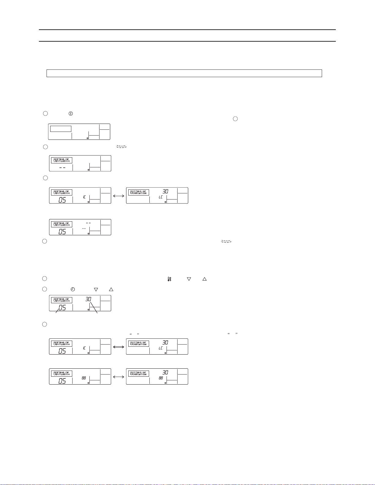
[ IV Remote Controller ]
[Operation Procedures]
<Indoor unit address and indoor unit> <LOSSNAY address and LOSSNAY>
- Without interlocked LOSSNAY settings
Search result
- The indoor unit address and the interlocked LOSSNAY address will appear alternately.
Press the [ON/OFF] button on the remote controller to bring the unit to a stop.
The display window on the remote controller must look like the figure below to proceed to step .
NOTE: When using LOSSNAY units in conjunction, interlock the addresses of all indoor units within the group and address of LOSSNAY units.
Perform this operation to enter the interlock setting between the LOSSNAY and the indoor units to which the remote controller is connected, or to
search and delete registered information.
* When the upper controller is connected, make the setting using the upper controller.
In the following example, the address of the indoor unit is 05 and the address of the LOSSNAY unit is 30.
2
< 1. Registration Procedures >
Indoor unit address LOSSNAY address
Press the [TEST] button to register the address of the selected indoor unit and the interlocked LOSSNAY unit.
- Registration completed
The registered indoor unit address and IC, and the interlocked LOSSNAY address and LC will appear alternately.
- Registration error
If the registration fails, the indoor unit address and the LOSSNAY address will be displayed alternately.
Registration cannot be completed: The selected unit address does not have a corresponding indoor unit or a LOSSNAY unit.
Registration cannot be completed: Another LOSSNAY has already been interlocked with the selected indoor unit.
1
3
2
Press and hold the [FILTER] and [ ] buttons simultaneously for two seconds to perform a search for the LOSSNAY that is interlocked with the
indoor unit to which the remote controller is connected.
If no settings are necessary, exit the window by pressing and holding the [FILTER] and [ ] buttons simultaneously for 2 seconds.
Go to step 1. Registration Procedures to make the interlock settings with LOSSNAY units, or go to step 2. Search Procedures to search for a
particular LOSSNAY unit.
Go to step 3. Deletion Procedures to delete any LOSSNAY settings.
To interlock an indoor unit with a LOSSNAY unit, press the [ TEMP. ( ) or ( )] button on the remote controller that is connected to the indoor
unit, and select its address (01 to 50).
Press the [ CLOCK ( ) or ( )] button to select the address of the LOSSNAY to be interlocked (01 to 50).
5
4
7
6
[3] Interlock Settings via the MA Remote Controller
1. LOSSNAY interlock setting (Make this setting only when necessary.)
(1) MA Remote Controller (PAR-21MAA)
HWE09120 GB
- 74 -
Page 84
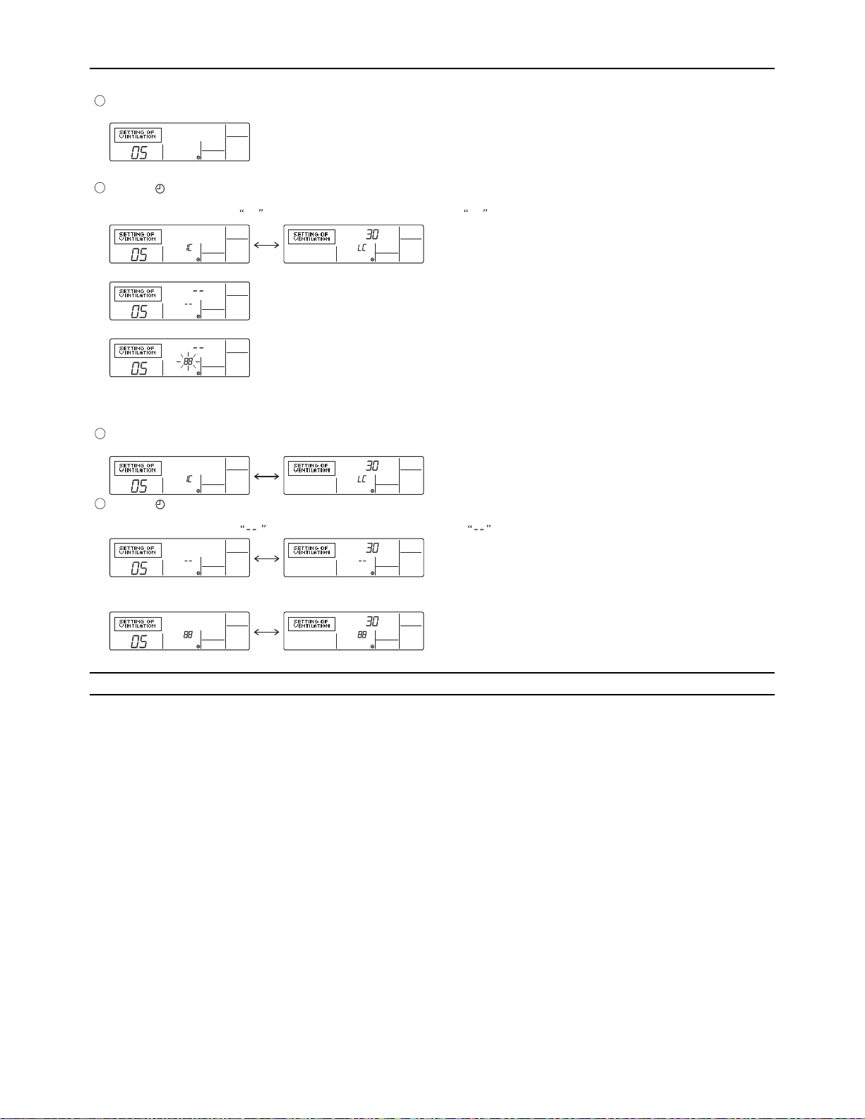
[ IV Remote Controller ]
<Indoor unit address>
- Search completed (No interlocked settings with a LOSSNAY exist.)
- The selected address does not have a corresponding indoor unit.
< 2. Search Procedures >
< 3. Deletion Procedures >
Press the [ MENU] button to search for the address of the LOSSNAY unit that is interlocked with the selected indoor unit.
- Search completed (With a LOSSNAY connection)
The indoor unit address and IC, and the interlocked LOSSNAY address and LC will appear alternately.
Take the following steps to delete the interlock setting between a LOSSNAY unit and the interlocked indoor unit from the remote controller
that is connected to the indoor unit.
Find the address of the LOSSNAY to be deleted (See section 2. Search Procedures. ), and bring up the result of the search for both the
indoor unit and LOSSNAY on the display.
Press the [ ON/OFF] button twice to delete the address of the LOSSNAY unit that is interlocked with the selected indoor unit.
- Registration completed
The indoor unit address and , and the interlocked LOSSNAY address and will appear alternately.
-Deletion error
If the deletion fails
8
9
10
11
To search for the LOSSNAY unit that is interlocked with a particular indoor unit, enter the address of the indoor unit into the remote controller that is
connected to it.
[4] Using the built-in Temperature Sensor on the Remote Controller
1. Selecting the position of temperature detection (Factory setting: SW1-1 on the controller board on the indoor unit is
set to OFF.)
To use the built-in sensor on the remote controller, set the SW1-1 on the controller board on the indoor unit to ON.
Some models of remote controllers are not equipped with a built-in temperature sensor. Use the built-in temperature sensor
on the indoor unit instead.
When using the built-in sensor on the remote controller, install the remote controller where room temperature can be detected.
HWE09120 GB
- 75 -
Page 85

[ IV Remote Controller ]
- 76 -
GBHWE09120
Page 86

V
Electrical Wiring Diagram
[1] Electrical Wiring Diagram of the Outdoor Unit .................................................................79
[2] Electrical Wiring Diagram of Transmission Booster......................................................... 84
HWE09120 GB
- 77 -
Page 87

- 78 -
Page 88
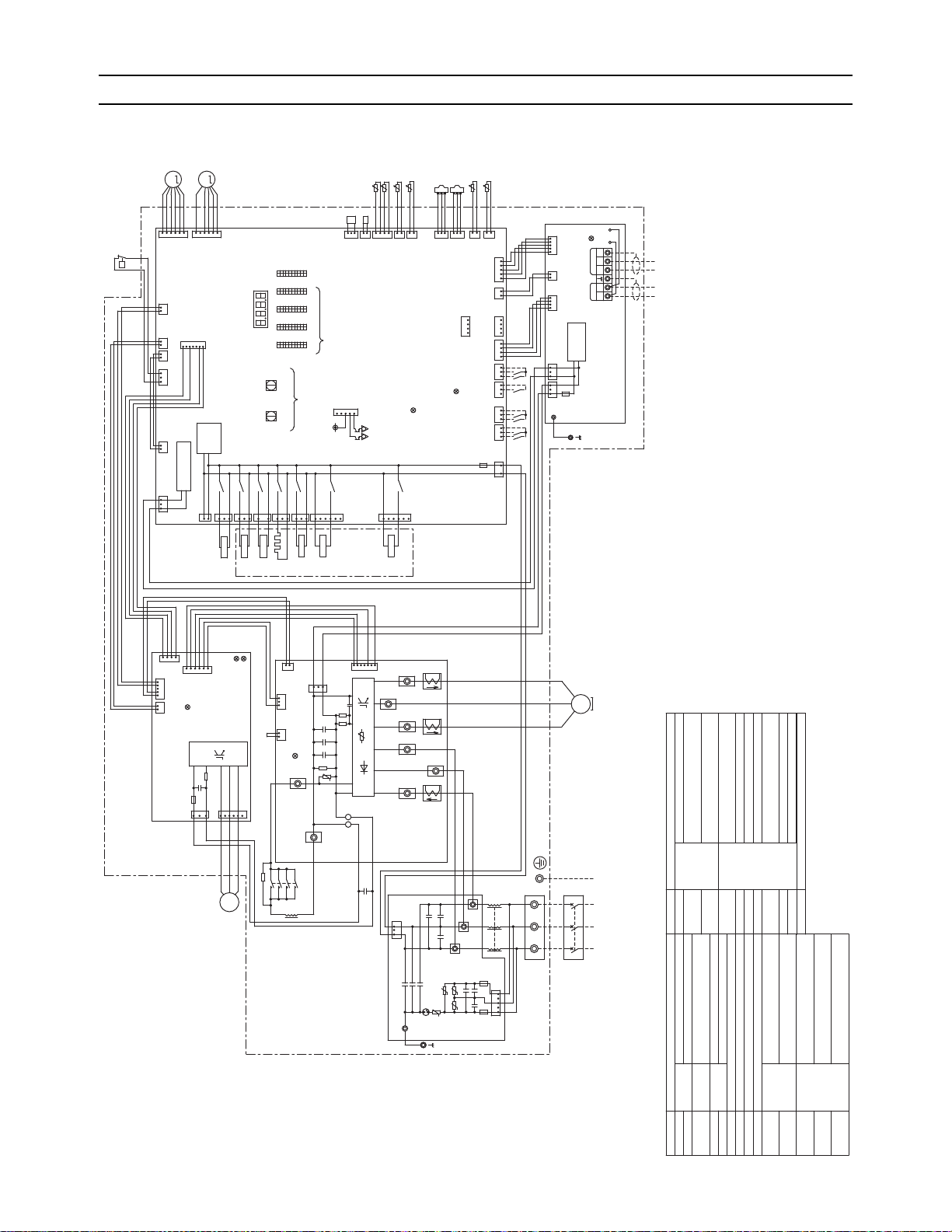
HIC bypass,Controls refrigerant
flow in HIC circuit
G
Ground
G
Explanation
Symbol
<Symbol explanation>
1
SV5b
X05
3
6
CN506
163
X09
CN508
black
SV9
L3L2
L1
1
SV1a
For opening/closing the bypass
circuit
Subcooled liquid refrigerant
temperature
Terminal
block
Central control transmission
cable
Indoor/Outdoor transmission
cable
Power supply
Function setting connector
IGBT temperature
OA temperature
ACC inlet pipe temperature
Discharge pipe temperature
Thermistor
Pipe temperature
Outdoor unit heat exchanger
capacity control
4-way valve
Explanation
CN504
green
3
1
CH11
3
1
X03
CN503
blue
72C
2
1
X02
CN502
3
1
X01
CN02
Motor
(Compressor)
TB21
F2
AC250V
6.3A T
CN5V
yellow
CN22
red
31
Fan motor
(Heat exchanger)
U
21
CNT01
V
M
3㨪
W
21
CN18V
blue
CNDC
pink
CN4
12 45
123
4
CN21
blue
12345
CPU power
supply circuit
1
F01
AC250V
3.15A T
CN03
black
1313
6
2
M-NET power
supply
circuit
12
2
M-NET Board
*4
7
4
TH2
TH4
tࠑ
tࠑ
321
Indoor/Outdoor
transmission
cable
Central control
transmission
cable
63HS1
5
red
CNAC
63LS
3
TP2
2
CN2
1
Control Board
LEV1
LEV2
3
TH5
M
TP1
TH6
TH7MTH3
TB3
M1 M2 M1 M2 S
TB7
123
6
tࠑ
4512
1234
tࠑ
1
21S4b
tࠑ
2
FAN Board
LED1
Unit address setting
tࠑ
LED1㧦Power supply to
ޓIndoor/Outdoor
ޓtransmission line
CN102
CNS2
yellow
SWU2
10's digit
SWU1
1's digit
10
1
10
1
10
1
10
1
SW4 SW3 SW2 SW1
ON
OFF ON
OFF ON OFF ON
X04
*3
LED3:Lit when powered
CN01
red
5
black
3
CNINV
1
3
CNVDC
CNIT
red
F01
AC250V
15A T
1
1
R630
3
654
3
1
2
C630
IPM
2
1
2
1
LED3:CPU in
operation
1
LED1:Normal
operation
2
1
1
OFF
2323123
blue
CN3N
yellow
CN3K
F01
AC250V
3.15A T
4521
OFF
432112 431
21234
6
21
CNLVA
122131
CN801
yellow
CNT02
CN332
blue
CN4
21223
3123
CN41CN102CN3D
4
1
red
CN3S
red
CNIT
yellow
CNS2
CN202
red
CN201
CN215
black
CN211
4321
Power selecting
connector
2
1
Z24
Z25
3
CNLVB
red
ON
CNTYP5
green
CNTYP4
green
CN990
CN40
LED2㧦CPU in operation
CN212
CN213
red
TB1
L3L2
whitered
Noise Filter
F1
AC250V
6.3A T
W
CX6
CY3
V
black
SC-V
7
tࠑ
black
INV Board
RSH2
3
ZNR1
C32
red
black
CN6
SC-U
CN2
SC-T
MS
3㨪
*5
CX5
C1
U
CN4
black
red
white
U
72C
31
R30
TB23
TB22
1
CT22
DSA1
black
1
CX2
CY1
CX1
Z3
CX3
Z4
Z1
U
SC-P2
3
CY2
CX4
black
white
*5
red
red
CT12
black
SC-W
1
SC-S
red
CT3
SC-R
red
R1
DCL
2
5
C31
C1
RSH1
U
C30
IGBT
CNDC
pink
LED1:Normal operation(Lit)
/Error(Blink)
2
1
2
THHS
1
L
TB-P
443334
*5
131423
43
24
white
red
white
CN501
21S4a
㧗㧗㧗
TB-N
SC-P1
1
P
63H1
Power supply
3㨪
60Hz
208/230V
CN04
red
LED2:Error
UZ2U
ONOFF
1
10
SW5
12V
5
4
3
1
CN51
*3
Function setting
LED1
Display
setting
Compressor ON/OFF output
Error detection output
L1
㧗
Pressure
sensor
Pressure
switch
High pressure protection for the
outdoor unit
Discharge pressure
Low pressure
Magnetic relay(inverter main circuit)
Current sensor(AC)
Crankcase heater(for heating the compressor)
Linear
expansion
valve
DC reactor
SV9
TB1
TB3
TB7
TH3
TH4
TH5
TH6
TH7
THHS
Z24,25
21S4a
Symbol
63H1
63HS1
63LS
72C
CH11
CT12,22,3
LEV1
DCL
SV5b
Cooling/Heating switching
Heat exchanger capacity control
21S4b
TH2
Subcool bypass outlet
temperature
LEV2
Pressure control,Refrigerant flow
rate control
SV1a
Solenoid
valve
For opening/closing the bypass
circuit under the O/S
white
CNAC2
black
132
1
X72
CN505
black
A1
A2
Power
failure
detection
circuit
*1. Single-dotted lines indicate wiring
not supplied with the unit.
*2. Dot-dash lines indicate the control
box boundaries.
*3. Refer to the Data book for connecting
input/output signal connectors.
*4. Daisy-chain terminals (TB3) on the
outdoor units in the same refrigerant
system together.
*5. Faston terminals have a locking
function.Make sure the terminals
are securely locked in place after
insertion.Press the tab on the
terminals to remove them.
[ V Electrical Wiring Diagram ]
V Electrical Wiring Diagram
[1] Electrical Wiring Diagram of the Outdoor Unit
1. Electrical wiring diagram of the outdoor unit
(1) PUHY-P72TJMU-A
HWE09120 GB
- 79 -
Page 89
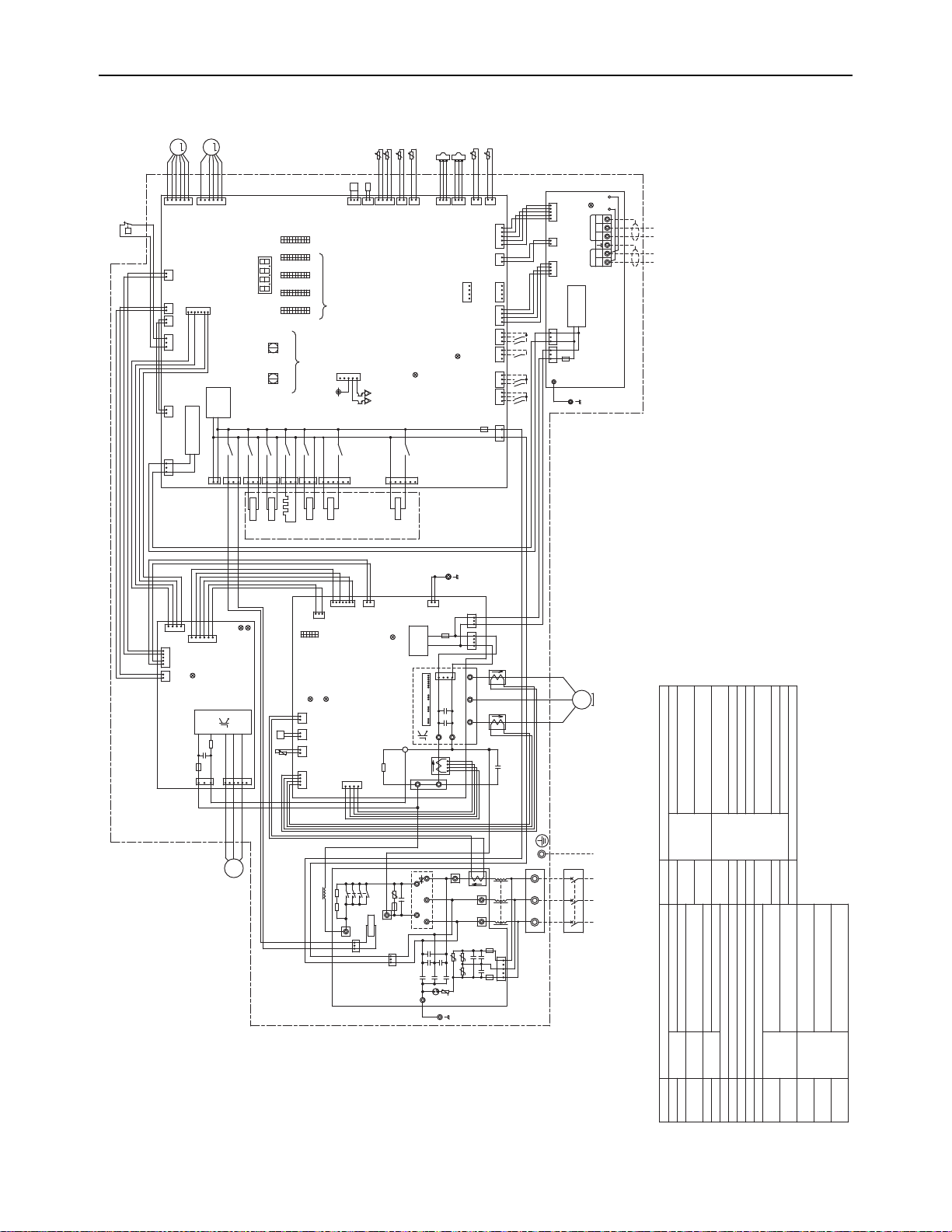
[ V Electrical Wiring Diagram ]
LED1:Normal operation(Lit)
/Error(Blink)
LED4:CPU in
operation
ON
CN5V
yellow
3
1
OFF
SW1
6
1
Function
setting
HIC bypass,Controls refrigerant
flow in HIC circuit
G
G
Ground
G
Explanation
Symbol
DCCT1 Current sensor(DC)
21S4b
X01
1
CN502
X02
1
2
CN503
blue
X03
1
3
CH11
CN501
3
X04
21S4a
CN504
green
3
116
3
X05
CN506
SV5b
For opening/closing the bypass
circuit
Subcooled liquid refrigerant
temperature
Terminal
block
Central control transmission
cable
Indoor/Outdoor transmission
cable
Power supply
Function setting connector
IGBT temperature
OA temperature
ACC inlet pipe temperature
Discharge pipe temperature
Thermistor
Pipe temperature
CN04
red
4-way valve
LED2:CPU in operation
CN3D
2
CN40
ON
LED3:Lit when powered
2t°112
32132
1
CN202
red
121
63HS1
CN211
TH4
3
1
TH2
12234
1
2
1
TH5
t°
CN990
CN212
CN213
red
Z25
Z24
CNTYP4
green
CNLVB
red
1
13
red
CNIT
4
Explanation
CN03
black
yellow
CNS2
*3
3
2
OFF
1
2
red
CN3S
51232132
yellow
CN3K
1
2
33
3
4
F01
AC250V
3.15A T
LEV1
21 1
blue
CN3N
Pressure
sensor
M
M
LEV2
CNLVA
122
Pressure
switch
CN102
2
CN18V
blue
High pressure protection for the
outdoor unit
LED3:CPU in
operation
F01
AC250V
15A T
LED3:Charge
2
4
1
C630
W
IPM
72C
CN03
black
~~~
C41
black
DSA1
IPM
FAN Board
CY2
Z4
U
CY3
CY1
CX6
CX4
U
Z2
Z3
TB23
U
CX1
-
1
Discharge pressure
F3
AC250V
6.3A T
CNDC2
1
*5
INV Board
SC-P1
CN02
Z5
Noise
Filter
TB42
3
CNCT
31
R2R1
DCL
72C
red
+
+
Diode Stack
U
*4
U
CX3
ACCT3
CNTYP
1
3
CN505
black
LED1
Power
failure
detection
circuit
CNDC
pink
X72
5
1
CNT02
black
CNIPM
W
F02
AC250V
3.15A T
ACCT1
V
C008
CNDC1
N
P
C007
U
white
1
1
TB3
red
V
IPM power
supply
circuit
CN2
CNCT3
black
LED1:Normal
operation
CN4
Power supply
3~
60Hz
208/230V
11
CNDC3
pink
2
CNFG
blue
3
t°
Low pressure
SWU2
Central control
transmission
cable
4
t°
4
25
Indoor/Outdoor
transmission
cable
10's digit
1
CNIT
red
S
TP2
CNS2
yellow
12
TP1
2
Magnetic relay(inverter main circuit)
TB7
3
F01
AC250V
3.15A T
45
M-NET power
supply
circuit
12
1
CN102
black
black
Current sensor(AC)
M-NET Board
432
Crankcase heater(for heating the compressor)
3
4
CNINV
261
CNTYP5
green
2
4
CN4
3
2
3
Error detection output
1
1
CN215
black
CN201
63LS
t°
3
1
CN4
LED2:Error
TH6
CN41
CN21
blue
t°
THHS
Z26
4
black
3121
SWU1
2
1
CNTH
green
3
7
521
white
U
1
red
1's digit
CX2
3
Compressor ON/OFF output
SW5
M
3~
U
Control Board
23
3
41
CNAC
red
1
752
63H1
CN801
yellow
*3
2
t°
LED1
Display
setting
3
Function setting
CN51
12V
10
1
536
TH7
P
CN2
5
TH3
Unit address setting
1
CN332
blue
211131
12
432
4
2
1
Linear
expansion
valve
R630
2
1
CNVDC
2
Power selecting
connector
Fan motor
(Heat exchanger)
1
3
DC reactor
1
SV9
TB31
1
654
3
R01
2
2
CNCT2
blue
4
Motor
(Compressor)
TB1
C1
DCCT1
ACCT2
FT-N
TB3
TB7
Z1
TB21
TH3
TH4
TB22
L
F2
AC250V
6.3A T
1
F1
AC250V
6.3A T
5
blackwhitered
TH5
TH6
TH7
THHS3Z24,25,26
CN01
L3
L3
L2
L2
L1
TB1
W
CNAC2
black
*1.Single-dotted lines indicate wiring
not supplied with the unit.
*2.Dot-dash lines indicate the control
box boundaries.
*3.Refer to the Data book for connecting
input/output signal connectors.
*4.Daisy-chain terminals (TB3) on the
outdoor units in the same refrigerant
system together.
*5.Faston terminals have a locking
function.Make sure the terminals
are securely locked in place after
insertion.Press the tab on the
terminals to remove them.
L1
21S4a
Symbol
63H1
63HS1
63LS
72C
CH11
ACCT1,2,3
LEV1
DCL
<Symbol explanation>
Cooling/Heating switching
Heat exchanger capacity control
21S4b
TH2
Subcool bypass outlet
temperature
LEV2
Pressure control,Refrigerant flow
rate control
SV1a
Solenoid
valve
For opening/closing the bypass
circuit under the O/S
SW1
OFF
10
ON OFF
CNT01
CX5
ON
10
1
SW2
OFF
10
ON
1
SW3
OFF ON
10
1
SW4
OFF ON
4
1
1
LED1:Power supply to
Indoor/Outdoor
transmission line
4
2
1
1
V
red
MS
3~
CN22
red
124
6
163
SV9
CN508
black
X09
M1 M2 M1 M2
CPU power
supply circuit
Outdoor unit heat exchanger
capacity control
SV5b
SV1a
(2) PUHY-P96TJMU-A
HWE09120 GB
- 80 -
Page 90

[ V Electrical Wiring Diagram ]
Contactor
Box
CNVDC
52F
Fan motor 2
(Heat exchanger)
Fan motor 1
(Heat exchanger)
CN12
black
white
red
black
white
red
642
1
black
white
red
TSR
W
V
U
A2
A1
LED1:Normal operation(Lit)
/Error(Blink)
TH3
TH7
TH6
TH5
TH2
TH4
52F Magnetic contactor(FAN)
Symbol
Explanation
For opening/closing the bypass
circuit under the O/S
Solenoid
valve
SV1a
Pressure control,Refrigerant flow
rate control
LEV2
Subcool bypass outlet
temperature
TH2
21S4b,c
Heat exchanger capacity control
Cooling/Heating switching
DCL
LEV1
ACCT1,2,3
CH11
72C
63LS
63HS1
63H1
Symbol
21S4a
Z24,25,26
THHS
TH7
TH6
TH5
TH4
TH3
TB1
DC reactor
Linear
expansion
valve
Crankcase heater(for heating the compressor)
Current sensor(AC)
Magnetic relay(inverter main circuit)
Low pressure
Discharge pressure
High pressure protection for the
outdoor unit
Pressure
switch
Pressure
sensor
Explanation
4-way valve
Pipe temperature
Thermistor
Discharge pipe temperature
ACC inlet pipe temperature
OA temperature
IGBT temperature
Function setting connector
Power supply
Terminal
block
Subcooled liquid refrigerant
temperature
Current sensor(DC)DCCT1
SV5b,c
Outdoor unit heat exchanger
capacity control
HIC bypass,Controls refrigerant
flow in HIC circuit
Indoor/Outdoor transmission cableTB3
Central control transmission cableTB7
For opening/closing the bypass circuitSV9
21S4b
X01
1
CN502
X02
1
2
CN503
blue
X03
1
3
CH11
CN501
3
X04
21S4a
CN504
green
3
116
3
X05
CN506
SV5b
635
1
SV5c
21S4c
CN507
red
X07
X08
CN04
red
LED2:CPU in operation
CN3D
2
CN40
ON
LED3:Lit when powered
2t°112
32132
1
CN202
red
121
63HS1
CN211
3
1122341
2
1
t°
CN990
CN212
CN213
red
Z25
Z24
CNTYP4
green
CNLVB
red
1
13
red
CNIT
4
CN03
black
yellow
CNS2
*3
3
2
OFF
1
2
red
CN3S
5123
2132
yellow
CN3K
1
2
3
3
3
4
F01
AC250V
3.15A T
LEV1
21 1
blue
CN3N
M
M
LEV2
CNLVA
122
CN102
2
CN18V
blue
LED3:CPU in
operation
F01
AC250V
15A T
LED3:Charge
2
4
1
C630
W
IPM
72C
CN03
black
~~~
C41
black
DSA1
IPM
FAN Board
CY2
Z4
U
CY3
CY1
CX6
CX4
U
Z2
Z3
TB23
U
CX1
-
1
F3
AC250V
6.3A T
CNDC2
1
*5
INV Board
SC-P1
CN02
Z5
Noise
Filter
TB42
3
CNCT
31
R2R1
DCL
72C
red
+
+
Diode Stack
U
*4
U
CX3
ACCT3
CNTYP
1
3
CN505
black
LED1
Power
failure
detection
circuit
CNDC
pink
X72
5
1
CNT02
black
CNIPM
F02
AC250V
3.15A T
ACCT1
V
C008
CNDC1
N
P
C007
U
white
1
1
TB3
red
IPM power
supply
circuit
CN2
CNCT3
black
LED1:Normal
operation
CN4
Power supply
3~
60Hz
208/230V
11
CNDC3
pink
2
CNFG
blue
3
t°
SWU2
Central control
transmission
cable
4
t°
4
25
Indoor/Outdoor
transmission
cable
10's digit
1
CNIT
red
S
TP2
CNS2
yellow
12
TP1
2
TB7
3
F01
AC250V
3.15A T
45
M-NET power
supply
circuit
12
1
CN102
black
black
M-NET Board
432
3
4
CNINV
261
CNTYP5
green
2
4
CN4
3
2
3
Error detection output
1
1
CN215
black
CN201
63LS
t°
3
1
CN4
LED2:Error
CN41
CN21
blue
t°
THHS
Z26
4
black
3121
SWU1
2
1
CNTH
green
3
7
521
white
U
1
red
1's digit
LED4:CPU in
operation
CX2
3
Compressor ON/OFF output
SW5
Control Board
23
3
41
CNAC
red
1
752
63H1
CN801
yellow
*3
2
t°
LED1
Display
setting
3
Function setting
CN51
12V
10
1
536
P
CN2
5
Unit address setting
1
CN332
blue
211131
12
432
4
2
1
R630
2
1
CN11
2
Power selecting
connector
1
3
1
TB31
1
654
3
R01
2
2
CNCT2
blue
4
Motor
(Compressor)
C1
DCCT1
ACCT2
FT-N
Z1
TB21 TB22
L
F2
AC250V
6.3A T
1
F1
AC250V
6.3A T
5
blackwhitered
3
CN01
L3
L3
L2
L2
L1
TB1
W
CNAC2
black
L1
SW1
OFF
10
ON OFF
CNT01
CX5
ON
10
1
SW2
OFF
10
ON
1
SW3
OFF ON
10
1
SW4
OFF ON
4
1
1
LED1:Power supply to
Indoor/Outdoor
transmission line
4
1
3
CN510
yellow
6
2
1
1
V
red
MS
3~
CN22
red
52F
1
Contactor Box
124
6
6
U
M
3~
V
W
642
1
163
SV9
CN508
black
X09
M1 M2 M1 M2
CPU power
supply circuit
1
5
X14
U
M
3~
V
W
CN5V
yellow
Function
setting
SW1
ONOFF
G
Ground
G
G
SV1a
*1.Single-dotted lines indicate wiring
not supplied with the unit.
*2.Dot-dash lines indicate the control
box boundaries.
*3.Refer to the Data book for connecting
input/output signal connectors.
*4.Daisy-chain terminals (TB3) on the
outdoor units in the same refrigerant
system together.
*5.Faston terminals have a locking
function.Make sure the terminals
are securely locked in place after
insertion.Press the tab on the
terminals to remove them.
<Symbol explanation>
(3) PUHY-P120, P144TJMU-A
HWE09120 GB
- 81 -
Page 91

[ V Electrical Wiring Diagram ]
+-
+
+
+
+
2
1
+++++
Transformer Box
*1.Single-dotted lines indicate wiring not supplied with the unit.
*2.Dot-dash lines indicate the control box boundaries.
*3.Refer to the Data book for connecting input/output signal connectors.
*4.Daisy-chain terminals (TB3) on the outdoor units in the
same refrigerant system together.
*5.Faston terminals have a locking function.
Make sure the terminals are securely locked
in place after insertion. Press the tab
on the terminals to remove them.
*6.Control box houses high-voltage parts.
Before inspecting the inside of the
control box,turn off the power,keep
the unit off for at least 10 minutes,
and confirm that the voltage between
FT-P and FT-N on INV Board has dropped
to DC20V or less.
HIC bypass,Controls refrigerant
flow in HIC circuit
Ground
G
GG
L3
L1
L2
Power Source
3~
60Hz
460V
T02
(Transformer)
CNTR2
432
1
1
2
3
4
T03
(Transformer)
CNTR3
21S4b
CN501
X01
1
3
X09
3
6
CN508
black
Unit address
setting
CN504
green
CT12
C31
C33
CN5
red
D1
R5
Z5
1
SV9
CNTR1
12
L1L2 L2
3
L3
45678
R631
white
TH2
t°
white
red
black
black
white
red
F4
AC600V
3A F
C8
F5
AC600V
3A F
red
CNIT
yellow
CNS2
t°
1
1
LED1
Display
setting
CN51
12V
Function
setting
SW1
10
1
CN212
CNTYP4
green
F4
AC250V
6.3A T
R4
F3
F1
Z4
R2
F2
*3
3
2
Compressor ON/OFF output
Error detection output
CN201
Z25
1
4
1
1
1
TH3
Z3
3
Z2
U
ONOFF
SW2
10
1
SWU2
LED1
C4
C35
C37
R31
R33
R30
ON
SW3
10
Control Board
TH7
CN40
63HS1
CN41
TH6
t°
t°
TH4
3
2
2
2
1
SW5
LED3:Lit when powered
1
3
4
R32
2
Z1
1
DSA
C10
R34 R35
LEV1
LEV2
C36
3
C34
SC-V
CT22
SC-U
V
1
CN4
blue
red
1
M
1
1
t°
LED3:CPU in
operation
black
4
1
CNTYP2
black
3
6
yellow
CN3K
*3
3
M
C3
TB21
C1
R3
3
CN1A
5
U
CN2
blue
CN3N
5
6
C7
U
44
R1
CN21
blue
TB1
1
CN1B
3
3
TB7 Power
selecting
connector
CN102
CNVDC
3
2
1
IPM
2
21
U
4
TP1
W
L3
DCL
V
black
72C
white
red
3
3
21
ON
OFF
12
M-NET power
supply circuit
123
C6
M-NET Board
12
1
Power failure
detection circuit
1
CNAC2
black
CN502
5
Indoor/Outdoor
transmission
cable
INV Board
red
3
CNT01
TB23
L2L1
U
4
1
ON
1
2
1's
digit
THHS
1
CNIT
red
S
2
1
1
CN990
1
3
W
TB3
10's
digit
OFF
LED2:CPU in operation
5
2
CNS2
yellow
TB7
1
CNDC
pink
M1
2
2
red
6
MS
3~
1
1
t°
C100
*5
3
3
U
1
4
LED1:Power supply to
Indoor/Outdoor
transmission line
ZNR01
M2
32
M1
black
Central control
transmission
cable
*6
SC-L1
1
4
C2
C9
ON
C5
OFF
FT-N
R5
M
3~
Motor
(Compressor)
CN5V
yellow
5
2
3
3
3
red
CN3S
1
1
CN04
red
1
CN2
2
3
CN4
X05
2
2
Fan motor
(Heat exchanger)
SC-P2
P
1
CN211
CN202
red
TH5
N
CN1
M2
2
TP2
LED1:Normal operation(Lit)
/ Error(Blink)
2
CN503
blue
5
X04
4
*4
SC-W
U
C32
SC-L3
CH11
CN506
1
2
CN72
red
3
P
63H1
CN801
yellow
1
2
CN332
blue
F1,F2,F3
AC250V
6.3A T
21
OFF
SW4
10
1
CNT02
11
CN3D
432
1
21
CPU power
supply circuit
CNAC
red
2
1
F01
AC250V
3.15A T
1
t°
ONOFF
10
SWU1
white
CN213
red
SC-L2
3
Z24
7
4
3 21122
7
1
2
CN5
1
CN4
red
CNINV
3
4
R630
1
1
C630
3
CN22
red
C631
5
F01
DC700V
4A T
1
CNTYP5
green
4
LED2:Error
21S4a
1
LED1:Normal
operation
2
3
2
U
X02
X03
CN18V
blue
5
1
7
CN4
3
CN6
2
IPM
4
SC-P1
FT-P
black
C30
red
DB1
CT3
72C
C1
CN2
CNTYP
black
R1
black
TB22
6
3
RSH1
CN102
3
R6
C17
1
1
1
FAN Board
63LS
ZNR1
U
L
3
Noise
Filter
SV5b
3
1
CN6
yellow
red
CNLVA
CNLVB
red
12345
6
white
black
SV1a
6
432
1
2
1
L1
L2 L3
CN215
black
For opening/closing the bypass
circuit
Terminal
block
Central control transmission
cable
Indoor/Outdoor transmission
cable
Power supply
Function setting connector
IGBT temperature
OA temperature
ACC inlet pipe temperature
Discharge pipe temperature
Thermistor
SV9
TB1
TB3
TB7
TH3
TH4
TH5
TH6
TH7
THHS
Z24,25
TH2
Subcool bypass outlet
temperature
DC reactor
Linear
expansion
valve
Crankcase heater(for heating the compressor)
Current sensor(AC)
Magnetic relay(inverter main circuit)
Low pressure
Discharge pressure
High pressure protection for the
outdoor unit
Pressure
switch
Cooling/Heating switching
Pressure
sensor
Explanation
4-way valve
Heat exchanger capacity control
For opening/closing the bypass
circuit under the O/S
Solenoid
valve
Pressure control,Refrigerant flow
rate control
DCL
LEV1
CT12,22,3
CH11
21S4b
72C
63LS
63HS1
63H1
<Symbol explanation>
Symbol
21S4a
LEV2
SV1a
SV5b
Outdoor unit heat exchanger
capacity control
Pipe temperature
Subcooled liquid refrigerant
temperature
(4) PUHY-P72, P96YJMU-A
HWE09120 GB
- 82 -
Page 92

[ V Electrical Wiring Diagram ]
+-
++++
2
1
+
++
++
Contactor
Box
W
V
CN11
1
black
2
8
7
5
red
white
8
M
3~
U
2
CN12
52F
TSR
black
white
red
black
white
red
W
V
U
U
V
W
5
1
7
A2
A1
Transformer Box
CNTR3
T03
(Transformer)
432
1
1
2
3
4
CNTR2
T02
(Transformer)
*1.Single-dotted lines indicate wiring not supplied with the unit.
*2.Dot-dash lines indicate the control box boundaries.
*3.Refer to the Data book for connecting input/output signal connectors.
*4.Daisy-chain terminals (TB3) on the outdoor units in the
same refrigerant system together.
*5.Faston terminals have a locking function.
Make sure the terminals are securely locked
in place after insertion. Press the tab
on the terminals to remove them.
*6.Control box houses high-voltage parts.
Before inspecting the inside of the
control box,turn off the power,keep
the unit off for at least 10 minutes,
and confirm that the voltage between
FT-P and FT-N on INV Board has dropped
to DC20V or less.
Magnetic contactor(FAN)52F
L3
L1
L2
Power Source3~60Hz
460V
Contactor Box
Fan motor 1
(Heat exchanger)
1
21S4b
21S4c
CN501
X01
1
3
X09
3
6
CN508
black
Unit address
setting
CN504
green
CT12
C31
C33
CN5
red
D1
R5
Z5
1
SV9
CNTR1
12
L1L2 L2
3
L3
45678
R631
white
TH2
t°
white
red
black
black
white
red
F4
AC600V
3A F
C8
F5
AC600V
3A F
red
CNIT
yellow
CNS2
t°
1
1
LED1
Display
setting
CN51
12V
Function
setting
SW1
10
1
CN212
CNTYP4
green
F4
AC250V
6.3A T
R4
F3
F1
Z4
R2
F2
*3
3
2
Compressor ON/OFF output
Error detection output
CN201
Z25
1
4
1
1
1
TH3
Z3
3
Z2
U
ONOFF
SW2
10
1
SWU2
LED1
C4
C35
C37
R31
R33
R30
ON
SW3
10
Control Board
TH7
CN40
63HS1
CN41
TH6
t°
t°
TH4
3
2
2
2
1
SW5
LED3:Lit when powered
1
3
4
R32
2
Z1
1
DSA
C10
R34 R35
LEV1
LEV2
C36
3
C34
SC-V
CT22
SC-U
V
1
CN4
blue
red
1
M
1
1
t°
LED3:CPU in
operation
black
4
1
CNTYP2
black
3
6
yellow
CN3K
*3
3
M
C3
TB21
C1
R3
3
CN1A
5
U
CN2
blue
CN3N
5
6
C7
U
44
R1
CN21
blue
TB1
1
CN1B
3
3
TB7 Power
selecting
connector
CN102
CNVDC
3
2
1
IPM
2
21
U
4
TP1
L3
DCL
black
72C
white
red
3
3
21
ON
OFF
12
M-NET power
supply circuit
123
C6
M-NET Board
12
1
Power failure
detection circuit
1
CNAC2
black
CN502
5
Indoor/Outdoor
transmission
cable
INV Board
red
3
CNT01
TB23
L2L1
Fan motor 2
(Heat exchanger)
4
1
ON
1
2
1's
digit
THHS
1
CNIT
red
S
2
1
1
CN990
1
3
W
TB3
10's
digit
OFF
LED2:CPU in operation
5
2
CNS2
yellow
TB7
1
CNDC
pink
M1
2
2
red
6
MS
3~
1
1
t°
C100
*5
3
3
U
1
4
LED1:Power supply to
Indoor/Outdoor
transmission line
ZNR01
M2
32
M1
black
Central control
transmission
cable
*6
SC-L1
1
4
C2
C9
ON
C5
OFF
FT-N
R5
M
3~
Motor
(Compressor)
CN5V
yellow
5
2
3
3
3
red
CN3S
1
1
CN04
red
1
CN2
2
3
CN4
X05
2
2
SC-P2
P
1
CN211
CN202
red
TH5
N
CN1
M2
2
TP2
LED1:Normal operation(Lit)
/ Error(Blink)
2
CN503
blue
5
X04
4
*4
SC-W
U
C32
SC-L3
CH11
CN506
1
2
CN72
red
3
P
63H1
CN801
yellow
1
2
CN332
blue
F1,F2,F3
AC250V
6.3A T
21
OFF
SW4
10
1
CNT02
11
CN3D
432
1
21
CPU power
supply circuit
CNAC
red
2
1
F01
AC250V
3.15A T
1
t°
CN507
red
ONOFF
10
SWU1
white
CN213
red
SC-L2
3
Z24
7
4
3 21122
7
1
2
CN5
1
CN4
red
CNINV
3
4
R630
1
1
C630
3
CN22
red
C631
5
F01
DC700V
4A T
1
CNTYP5
green
4
LED2:Error
21S4a
1
LED1:Normal
operation
2
3
2
U
X02
X03
CN18V
blue
5
1
7
CN4
3
CN6
2
IPM
4
SC-P1
FT-P
black
C30
red
DB1
CT3
72C
C1
CN2
CNTYP
black
R1
black
TB22
6
3
RSH1
CN102
3
R6
C17
1
1
1
FAN Board
63LS
ZNR1
U
L
3
Noise
Filter
SV5b
X08
3
1
CN6
yellow
red
SV5c
X07
356
6
5
X14
CN510
yellow
1
CNLVA
CNLVB
red
12345
6
white
black
SV1a
52F
G
Ground
6
432
1
G
G
2
1
L1 L2 L3
CN215
black
HIC bypass,Controls refrigerant
flow in HIC circuit
For opening/closing the bypass
circuit
Terminal
block
Central control transmission
cable
Indoor/Outdoor transmission
cable
Power supply
Function setting connector
IGBT temperature
OA temperature
ACC inlet pipe temperature
Discharge pipe temperature
Thermistor
SV9
TB1
TB3
TB7
TH3
TH4
TH5
TH6
TH7
THHS
Z24,25
TH2
Subcool bypass outlet
temperature
DC reactor
Linear
expansion
valve
Crankcase heater(for heating the compressor)
Current sensor(AC)
Magnetic relay(inverter main circuit)
Low pressure
Discharge pressure
High pressure protection for the
outdoor unit
Pressure
switch
Cooling/Heating switching
Pressure
sensor
Explanation
4-way valve
Heat exchanger capacity control
For opening/closing the bypass
circuit under the O/S
Solenoid
valve
Pressure control,Refrigerant flow
rate control
DCL
LEV1
CT12,22,3
CH11
21S4b,c
72C
63LS
63HS1
63H1
<Symbol explanation>
Symbol
21S4a
LEV2
SV1a
SV5b,c
Outdoor unit heat exchanger
capacity control
Pipe temperature
Subcooled liquid refrigerant
temperature
(5) PUHY-P120, P144YJMU-A
HWE09120 GB
- 83 -
Page 93

[ V Electrical Wiring Diagram ]
AC208V/230V
L
Red
Red Red
White
Green
250V 2A
Grounding
Red
Red
Red
U
U
White
White White
White
White
White BlueRedRed
DSA
White
White
Blue
Red
Red
Red
Red
Varistor
Varistor
Noise filter
Stabilized power supply
4
3
2
1
1
2
3
CN2
CN1
Black
Black
Black
Black
Green/Yellow
1
2
3
E
4
Choke coil
12
CN3
1212
CN4
CN2
1
2
CN1
Electronic control board
Black
White
Red
Red
Black
S
B
A
S
B
A
Terminal block 2 for
transmission line (TB3)
Expanded (indoor unit) side
Terminal block 1 for
transmission line (TB2)
Expanded (outdoor unit) side
Terminal block for power supply
(TB1)
[2] Electrical Wiring Diagram of Transmission Booster
HWE09120 GB
- 84 -
Page 94

VI
Refrigerant Circuit
[1] Refrigerant Circuit Diagram ............................................................................................. 87
[2] Principal Parts and Functions .......................................................................................... 88
HWE09120 GB
- 85 -
Page 95

- 86 -
Page 96
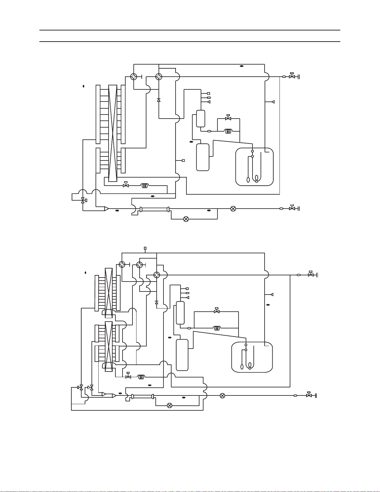
[ VI Refrigerant Circuit ]
HEX
O/S
Comp
ACC
CP2SV9
BV1
BV2
ST2
ST1
LEV2
CV
SV5b
63LS
CJ1
CP1
TH5
21S4b
TH6
TH7
TH3
TH2
TH4
CJ2
ST7
63HS1
ST6
ST3
21S4a
63H1
SV1a
LEV1
SCC
CV
TH7
HEX2
HEX1
TH3
SV5c
SV5b
21S4a
21S4c
21S4b
CJ2
TH2
SV9 CP2
63H1
ST3
63HS1
CJ1
O/S
TH4
Comp
ACC
ST6
ST7
SV1a
CP1
TH5
63LS
BV1
ST1
SCC
LEV1
TH6
LEV2
ST2
BV2
VI Refrigerant Circuit
[1] Refrigerant Circuit Diagram
1. Outdoor unit
(1) PUHY-P72, P96 models
(2) PUHY-P120, P144 models
HWE09120 GB
- 87 -
Page 97
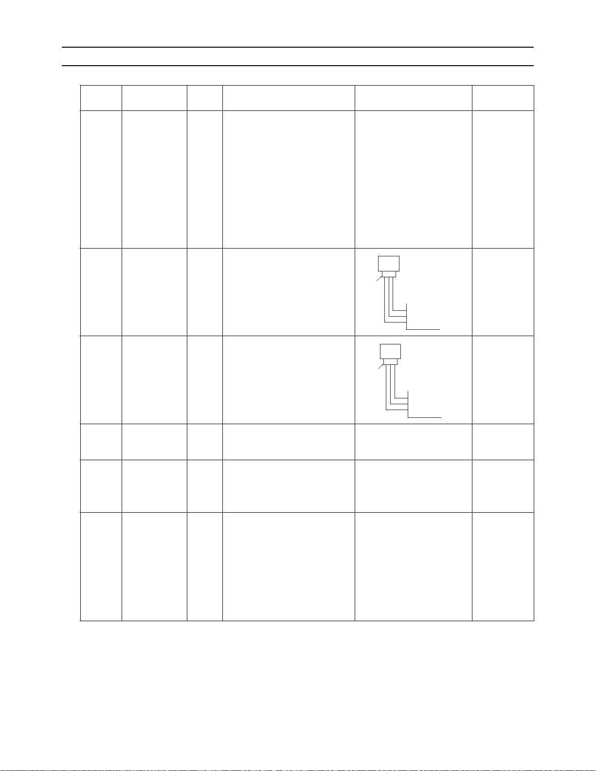
[ VI Refrigerant Circuit ]
Pressure
0~4.15 MPa [601psi]
Vout 0.5~3.5V
0.071V/0.098 MPa [14psi]
Pressure [MPa]
=1.38 x Vout [V]-0.69
Pressure [psi]
=(1.38 x Vout [V] - 0.69) x 145
GND (Black)
Vout (White)
Vcc (DC5V) (Red)
Connector
63HS1
1
123
2
3
[2] Principal Parts and Functions
1. Outdoor unit
Part
name
Compressor
High
pressure
sensor
Low
pressure
sensor
Symbols
(functions)
MC1
(Comp1)
Notes Usage Specifications Check method
Adjusts the amount of circulating
refrigerant by adjusting the operating frequency based on the operating pressure data
63HS1 1) Detects high pressure
2) Regulates frequency and provides high-pressure protection
63LS 1) Detects low pressure
2) Provides low-pressure protection
P72 model
Low-pressure shell scroll
compressor
Wirewound resistance
20°C[68°F] :
0.2ohm(TJMU)
0.71ohm(YJMU)
P96,P120,P144 models
Low-pressure shell scroll
compressor
Wirewound resistance
20°C[68°F] :
0.092ohm(TJMU)
0.323ohm(YJMU)
Pressure
63LS
0~1.7 MPa [247psi]
Vout 0.5~3.5V
123
0.173V/0.098 MPa [14psi]
Connector
Pressure [MPa]
=0.566 x Vout [V] - 0.283
Pressure [psi]
=(0.566 x Vout [V] - 0.283) x 145
1
GND (Black)
2
Vout (White)
3
Vcc (DC5V) (Red)
Pressure
switch
Power
supply
transformer
63H1 1) Detects high pressure
2) Provides high-pressure protection
Trans former YJMU
only
Decreases the power supply voltage (460V) supplied to the circuit
board
4.15MPa[601psi] OFF setting
Primary rated voltage:
460V, 50/60Hz
Secondary rated voltage:
229V
(No-load voltage)
Electromagnetic
contactor
52F P120
and
P144
only
Turns ON and OFF the output to
the fan motor.
AC208-230V Refer to the
section on
troubleshooting the outdoor
unit fan
(page 243) for
the ON/OFF
pattern of the
electromagnetic contactors.
HWE09120 GB
- 88 -
Page 98
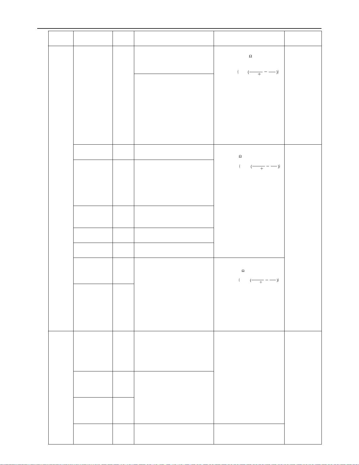
[ VI Refrigerant Circuit ]
R = 7.465k
120
R = 4057
R =
7.465
25/120
t
4057
273 t
1
393
1
exp
R = 15k
0
R = 3460
R = 15
0/80
t
3460
273 t
1
273
1
exp
R = 17k
50
R = 4016
R = 17
25/120
t
4016
273 t
1
323
1
exp
Part
name
Thermistor
Symbols
(functions)
TH4
(Discharge)
Notes
Usage Specifications Check method
1) Detects discharge air temperature
Degrees Celsius Resistance
check
2) Provides high-pressure protection
0°C[32°F] :698kohm
10°C[50°F] :413kohm
20°C[68°F] :250kohm
30°C[86°F] :160kohm
40°C[104°F] :104kohm
50°C[122°F] : 70kohm
60°C[140°F] : 48kohm
70°C[158°F] : 34kohm
80°C[176°F] : 24kohm
90°C[194°F] :17.5kohm
100°C[212°F] :13.0kohm
110°C[230°F] : 9.8kohm
TH2 LEV 1 is controlled based on the
TH2, TH3, and TH6 values.
TH3
(Pipe
temperature)
1) Controls frequency
2) Controls defrosting during
heating operation
3) Detects subcool at the heat
exchanger outlet and controls
LEV1 based on HPS data
and TH3 data
TH7
(Outdoor temperature)
1) Detects outdoor air temperature
2) Controls fan operation
Degrees Celsius
0°C[32°F] :15kohm
10°C[50°F] :9.7kohm
20°C[68°F] :6.4kohm
25°C[77°F] :5.3kohm
30°C[86°F] :4.3kohm
40°C[104°F] :3.1kohm
Resistance
check
TH5 LEV2 is controlled based on the
63LS and TH5 values.
TH6 Controls LEV1 based on TH2,
TH3, and TH6 data.
THHS
Inverter
Controls inverter cooling fan
based on THHS temperature
Degrees Celsius
heat sink temperature
THBOX
Control box internal temperature detection
0°C[32°F] :161kohm
10°C[50°F] :97kohm
20°C[68°F] :60kohm
25°C[77°F] :48kohm
30°C[86°F] :39kohm
40°C[104°F] :25kohm
Solenoid
valve
SV1a
Discharge-suction
bypass
1) High/low pressure bypass at
start-up and stopping, and
capacity control during lowload operation
AC208-230V
Open while being powered/
closed while not being powered
Continuity
check with a
tester
2) High-pressure-rise prevention
SV5b
Heat
Controls outdoor unit heat ex-
changer capacity
exchanger
capacity control
SV5c
For controlling
heat exchanger
capacity
P120,
P144
moels
only
SV9 High-pressure-rise prevention Open while being powered/
closed while not being powered
HWE09120 GB
- 89 -
Page 99

[ VI Refrigerant Circuit ]
Part
name
Linear
expansion
Symbols
(functions)
LEV1
(SC control)
Notes Usage Specifications Check method
Adjusts the amount of bypass flow
from the liquid pipe on the outdoor
unit during cooling
valve
LEV2
(Refrigerant
Adjusts refrigerant flow during
heating
flow adjustment)
Heater CH11 Heats the refrigerant in the com-
pressor
4-way
valve
21S4a Changeover between heating and
cooling
21S4b 1) Changeover betwee n heating
21S4c P120,
P144
moels
and cooling
2) Controls outdoor unit heat exchanger capacity
only
Fan motor
FAN motor 1,2 FAN
motor 2
is only
on the
P120
Regulates the heat exchanger capacity by adjusting the operating
frequency and operating the propeller fan based on the operating
pressure.
and
P144
models.
DC12V
Opening of a valve driven by a
stepping motor 0-480 pulses
(direct driven type)
DC12V
Opening of a valve driven by a
stepping motor 2100 pulses
(Max. 3000 pulses)
Belt heater
P72 model
1511 ohm 35W (AC230V)
P96, P120, and P144 models
1280 ohm 45W (AC240V)
AC208-230V
Dead: cooling cycle
Live: heating cycle
AC208-230V
Dead: cooling cycle
Outdoor unit heat exchanger
capacity at 100%
Live: heating cycle
Outdoor unit heat exchanger
capacity at 50%
or heating cycle
(TJMU)
AC180V, 50.5Hz, 920W
(YJMU)
AC414V, 50.5Hz, 920W
Same as indoor LEV
The resistance
value differs
from that of the
indoor LEV.
(Refer to the
section "LEV
Troubleshooti
ng.")(page 24
5)
Same as indoor LEV
Resistance
check
Continuity
check with a
tester
HWE09120 GB
- 90 -
Page 100
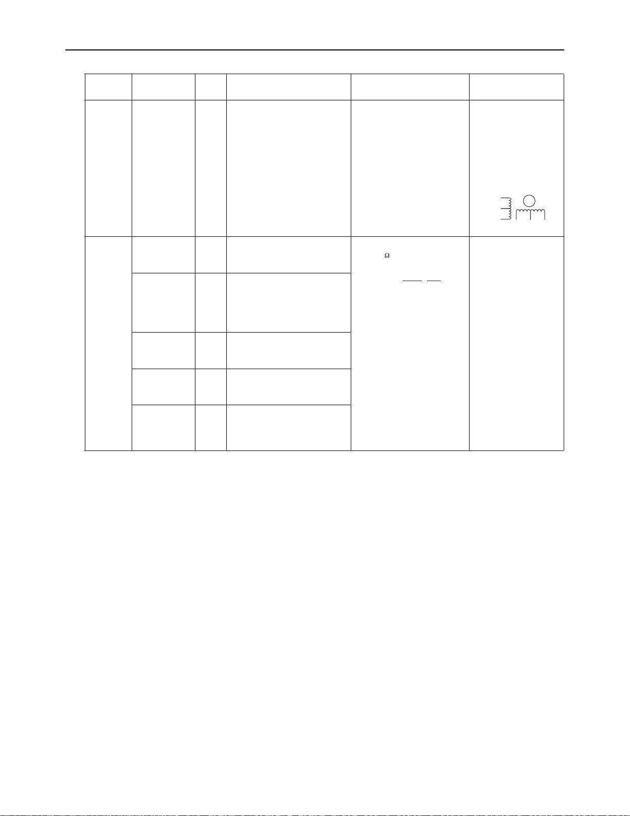
[ VI Refrigerant Circuit ]
1
273+t
R0=15k
R
0/80
=3460
Rt =
15exp{3460( - )}
1
273
2. Indoor Unit
Part
Name
Linear
expansion valve
Thermistor
Symbol
(functions)
Notes Usage Specification Check method
LEV 1) Adjusts superheat at the
indoor heat exchanger
outlet during cooling
2) Adjusts subcool at the
heat exchanger outlet of
the indoor unit during
cooling
TH1
Indoor unit control (Thermo)
(Suction air
temperature)
TH2
(Pipe temperature)
1) Indoor unit control (Frost
prevention, Hot adjust)
2) LEV control during heating operation (subcool
detection).
TH3
(Gas pipe
LEV control during cooling operation (superheat detection)
temperature)
TH4
Indoor unit control (Thermo)
Outdoor air
temperature)
Temperature
Indoor unit control (Thermo)
sensor (Indoor air temperature)
DC12V
Opening of stepping motor
driving valve 0-(1400) pulses
0°C [32°F]:15kohm
10°C [50°F] :9.7kohm
20°C [68°F]:6.4kohm
25°C [77°F] :5.3kohm
30°C [86°F] :4.3kohm
40°C [104°F] :3.1kohm
Refer to the section
"Continuity Test with a
Tester".
Continuity between
white, red, and orange.
Continuity between
yellow, brown, and
blue.
White
Red
Orange
Yellow
M
Brown Blue
Resistance check
HWE09120 GB
- 91 -
 Loading...