

Page 1

AIR CONDITIONERS CITY MULTI
Models PURY-P400, P500YMF-C
Service Handbook
Page 2

Page 3

Contents
1 PRECAUTIONS FOR DEVICES THA T USE R407C REFRIGERANT ..... 3
[1] Storage of Piping Material................................................................. 4
[2] Piping Machining............................................................................... 5
[3] Brazing.............................................................................................. 6
[4] Airtightness Test................................................................................ 7
[5] Vacuuming ........................................................................................ 7
[6] Charging of Refrigerant..................................................................... 8
[7] Dryer ................................................................................................. 8
2 COMPONENT OF EQUIPMENT ............................................................. 9
[1] Appearance of Components ............................................................. 9
[2] Refrigerant Circuit Diagram and Thermal Sensor ........................... 17
[3] Electrical Wiring Diagram................................................................ 20
[4] Standard Operation Data ................................................................ 24
[5] Function of Dip SW and Rotary SW................................................ 26
3 TEST RUN .............................................................................................29
[1] Before T est Run............................................................................... 29
[2] Test Run Method............................................................................. 33
4 GROUPING REGISTRATION OF INDOOR UNITS WITH M-NET
REMOTE CONTROLLER ...................................................................... 34
5 CONTROL.............................................................................................. 40
[1] Control of Outdoor Unit ................................................................... 40
[2] Control of BC Controller.................................................................. 49
[3] Operation Flow Chart...................................................................... 50
[4] List of Major Component Functions ................................................ 56
[5] Resistance of Temperature Sensor................................................. 59
6 REFRIGERANT AMOUNT ADJUSTMENT............................................ 60
[1] Operating Characteristics and Refrigerant Amount ........................ 60
[2] Adjustment and Judgement of Refrigerant Amount........................ 60
[3] Refrigerant Volume Adjustment Mode Operation............................ 62
7 TROUBLESHOOTING ...........................................................................66
[1] Principal Parts................................................................................. 66
[2] BC Controller Disassembly Procedure............................................ 99
[3] Self-diagnosis and Countermeasures Depending on the Check
Code Displayed............................................................................. 104
[4] LED Monitor Display ..................................................................... 121
8 PREP ARATION, REPAIRS AND REFRIGERANT REFILLING WHEN
REP AIRING LEAKS ............................................................................. 141
[1] Location of leaks:
[2] Location of leaks: Outdoor unit (Cooling mode)............................ 142
[3] Location of leaks:
[4] Location of leaks: Outdoor unit (when heating)............................. 143
Extension piping or indoor units (when cooling) ...
Extension piping or indoor units (Heating mode)..
141
142
9 CHECK THE COMPOSITION OF THE REFRIGERANT
(PURY -P200·250YMF-C only).................................................................144
–1–
Page 4
Safety precautions
Before installation and electric work
▲
Before installing the unit, make sure you read all
the “Safety precautions”.
▲
The “Safety precautions” provide very important
points regarding safety . Make sure you follow
them.
▲
This equipment may not be applicable to
EN61000-3-2: 1995 and EN61000-3-3: 1995.
▲
This equipment may have an adverse effect on
equipment on the same electrical supply system.
▲
Please report to or take consent by the supply
authority before connection to the system.
Symbols used in the text
Warning:
Describes precautions that should be observed to
prevent danger of injury or death to the user.
Caution:
Describes precautions that should be observed to
prevent damage to the unit.
Symbols used in the illustrations
: Indicates an action that must be avoided.
: Indicates that important instructions must be followed.
: Indicates a part which must be grounded.
: Beware of electric shock (This symbol is displayed on the
main unit label.) <Color: Yellow>
Warning:
Carefully read the labels affixed to the main unit.
Warning:
• Use the specified cables for wiring. Make the connections
securely so that the outside force of the cable is not
applied to the terminals.
- Inadequate connection and fastening may generate heat and
cause a fire.
• Have all electric work done by a licensed electrician
according to “Electric Facility Engineering Standard” and
“Interior Wire Regulations”and the instructions given in
this manual and always use a special circuit.
- If the power source capacity is inadequate or electric work is
performed improperly, electric shock and fire may result.
• Securely install the cover of control box and the panel.
- If the cover and panel are not installed properly, dust or water
may enter the outdoor unit and fire or electric shock may
result.
• After completing service work, make sure that refrigerant
gas is not leaking.
- If the refrigerant gas leaks and is exposed to a fan heater,
stove, oven, or other heat source, it may generate noxious
gases.
• Do not reconstruct or change the settings of the protection
devices.
- If the pressure switch, thermal switch, or other protection
device is shorted and operated forcibly, or parts other than
those specified by Mitsubishi Electric are used, fire or
explosion may result.
–2–
Page 5
11
1 PRECAUTIONS FOR DEVICES THAT USE R407C REFRIGERANT
11
Caution
Do not use the existing refrigerant piping.
• The old refrigerant and refrigerator oil in the existing
piping contains a large amount of chlorine which may
cause the refrigerator oil of the new unit to deteriorate.
Use refrigerant piping made of phosphorus deoxidized copper and copper alloy seamless pipes and
tubes”. In addition, be sure that the inner and outer
surfaces of the pipes are clean and free of hazardous
sulphur, oxides, dust/dirt, shaving particles, oils,
moisture, or any other contaminant.
• Contaminants on the inside of the refrigerant piping
may cause the refrigerant residual oil to deteriorate.
Store the piping to be used during installation indoors
and keep both ends of the piping sealed until just
before brazing. (Store elbows and other joints in a
plastic bag.)
• If dust, dirt, or water enters the refrigerant cycle,
deterioration of the oil and compressor trouble may
result.
Use a vacuum pump with a reverse flow check valve.
• The vacuum pump oil may flow back into the refrigerant cycle and cause the refrigerator oil to deteriorate.
Do not use the following tools that have been used
with conventional refrigerants.
(Gauge manifold, charge hose, gas leak detector, reverse flow check valve, refrigerant charge base,
vacuum gauge, refrigerant recovery equipment)
• If the conventional refrigerant and refrigerator oil are
mixed in the R407C, the refrigerant may deteriorated.
• If water is mixed in the R407C, the refrigerator oil
may deteriorate.
• Since R407C does not contain any chlorine, gas
leak detectors for conventional refrigerants will not
react to it.
Do not use a charging cylinder.
• Using a charging cylinder may cause the refrigerant
to deteriorate.
Be especially careful when managing the tools.
Use ester oil, ether oil or alkylbenzene (small
amount) as the refrigerator oil to coat flares and
flange connections.
• The refrigerator oil will degrade if it is mixed with a
large amount of mineral oil.
Use liquid refrigerant to seal the system.
• If gas refrigerant is used to seal the system, the composition of the refrigerant in the cylinder will change
and performance may drop.
Do not use a refrigerant other than R407C.
• If another refrigerant (R22, etc.) is used, the chlorine
in the refrigerant may cause the refrigerator oil to deteriorate.
• If dust, dirt, or water gets in the refrigerant cycle, the
refrigerant may deteriorate.
If the refrigerant leaks, recover the refrigerant in the
refrigerant cycle, then recharge the cycle with the
specified amount of the liquid refrigerant indicated
on the air conditioner.
• Since R407C is a nonazeotropic refrigerant, if additionally charged when the refrigerant leaked, the composition of the refrigerant in the refrigerant cycle will
change and result in a drop in performance or abnormal stopping.
–3–
Page 6
[1] Storage of Piping Material
(1) Storage location
Store the pipes to be used indoors. (Warehouse at site or owner’s warehouse)
Storing them outdoors may cause dirt, waste, or water to infiltrate.
(2) Pipe sealing before storage
Both ends of the pipes should be sealed until immediately before brazing.
Wrap elbows and T’s in plastic bags for storage.
* The new refrigerator oil is 10 times more hygroscopic than the conventional refrigerator oil (such as Suniso). Water
infiltration in the refrigerant circuit may deteriorate the oil or cause a compressor failure. Piping materials must be
stored with more care than with the conventional refrigerant pipes.
–4–
Page 7
[2] Piping Machining
Use ester oil, ether oil or alkylbenzene (small amount) as the refrigerator oil to coat flange connections.
Use only the necessary minimum quantity of oil !
Reason :
1. The refrigerator oil used for the equipment is highly hygroscopic and may introduce water inside.
Notes :
• Introducing a great quantity of mineral oil into the refrigerant circuit may also cause a compressor failure.
• Do not use oils other than ester oil, ether oil or alkylbenzene.
–5–
Page 8
[3] Brazing
No changes from the conventional method, but special care is required so that foreign matter (ie. oxide scale, water, dirt,
etc.) does not enter the refrigerant circuit.
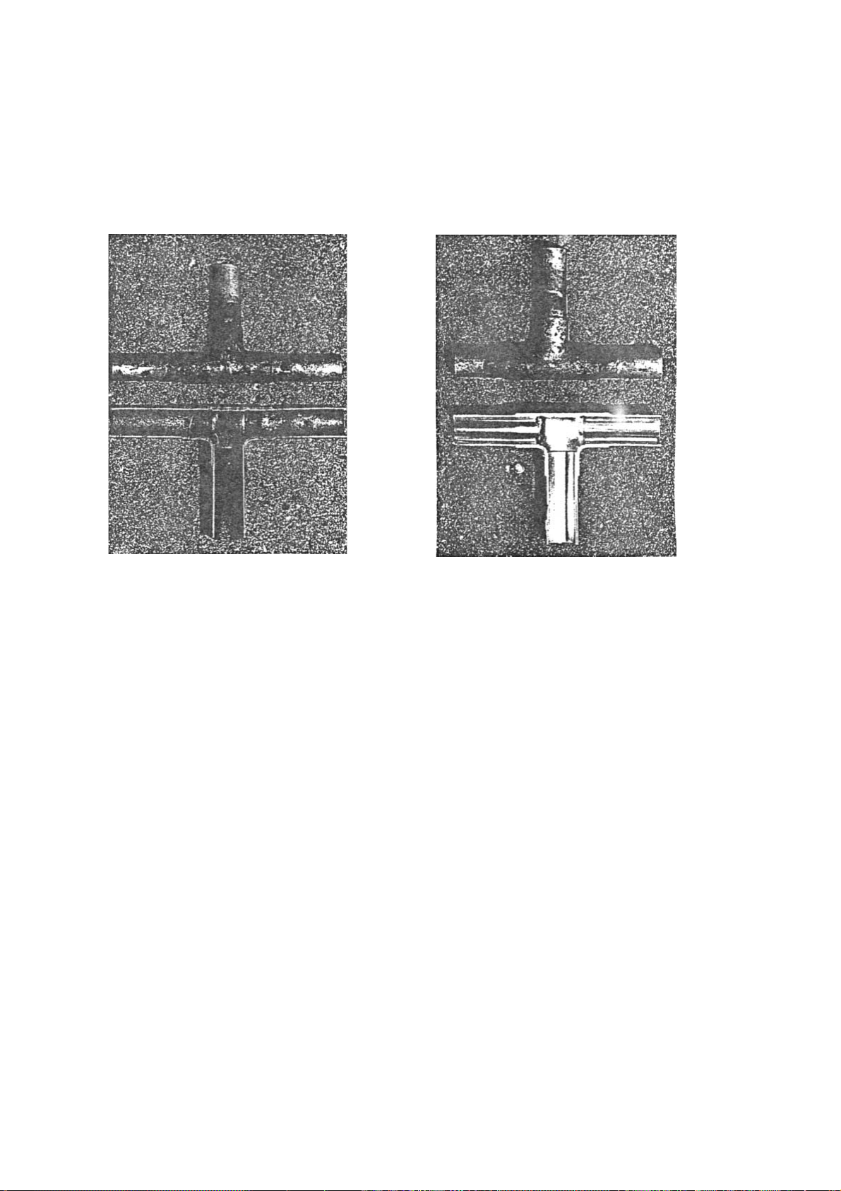
Example : Inner state of brazed section
When non-oxide brazing was not used When non-oxide brazing was used
Items to be strictly observed :
1. Do not conduct refrigerant piping work outdoors on a rainy day.
2. Apply non-oxide brazing.
3. Use a brazing material (Bcup-3) which requires no flux when brazing between copper pipes or between a copper pipe
and copper coupling.
4. If installed refrigerant pipes are not immediately connected to the equipment, then braze and seal both ends of them.
Reasons :
1. The new refrigerant oil is 10 times more hygroscopic than the conventional oil. The probability of a machine failure if
water infiltrates is higher than with conventional refrigerant oil.
2. A flux generally contains chlorine. A residual flux in the refrigerant circuit may generate sludge.
Note :
• Commercially available antioxidants may have adverse effects on the equipment due to its residue, etc. When
applying non-oxide brazing, use oxygen free nitrogen (OFN).
–6–
Page 9
[4] Airtightness Test
No changes from the conventional method. Note that a refrigerant leakage detector for R22 cannot detect R407C
leakage.
Halide torch R22 leakage detector
Items to be strictly observed :
1. Pressurize the equipment with nitrogen up to the design pressure and then judge the equipment’s airtightness, taking
temperature variations into account.
2. When investigating leakage locations using a refrigerant, be sure to use R407C.
3. Ensure that R407C is in a liquid state when charging.
Reasons :
1. Use of oxygen as the pressurized gas may cause an explosion.
2. Charging with R407C gas will lead the composition of the remaining refrigerant in the cylinder to change and this
refrigerant can then not be used.
Note :
• A leakage detector for R407C is sold commercially and it should be purchased.
[5] Vacuuming
1. Vacuum pump with check valve
A vacuum pump with a check valve is required to prevent the vacuum pump oil from flowing back into the refrigerant
circuit when the vacuum pump power is turned off (power failure).
It is also possible to attach a check valve to the actual vacuum pump afterwards.
2. Standard degree of vacuum for the vacuum pump
Use a pump which reaches 0.5 Torr (500 MICRON) or below after 5 minutes of operation.
In addition, be sure to use a vacuum pump that has been properly maintained and oiled using the specified oil. If the
vacuum pump is not properly maintained, the degree of vacuum may be too low.
3. Required accuracy of the vacuum gauge
Use a vacuum gauge that can measure up to 5 Torr. Do not use a general gauge manifold since it cannot measure a
vacuum of 5 Torr.
4. Evacuating time
• Evacuate the equipment for 1 hour after –755 mmHg (5 Torr) has been reached.
• After envacuating, leave the equipment for 1 hour and make sure that the vacuum is not lost.
5. Operating procedure when the vacuum pump is stopped
In order to prevent a backflow of the vacuum pump oil, open the relief valve on the vacuum pump side or loosen the
charge hose to drawn in air before stopping operation.
The same operating procedure should be used when using a vacuum pump with a check valve.
–7–
Page 10
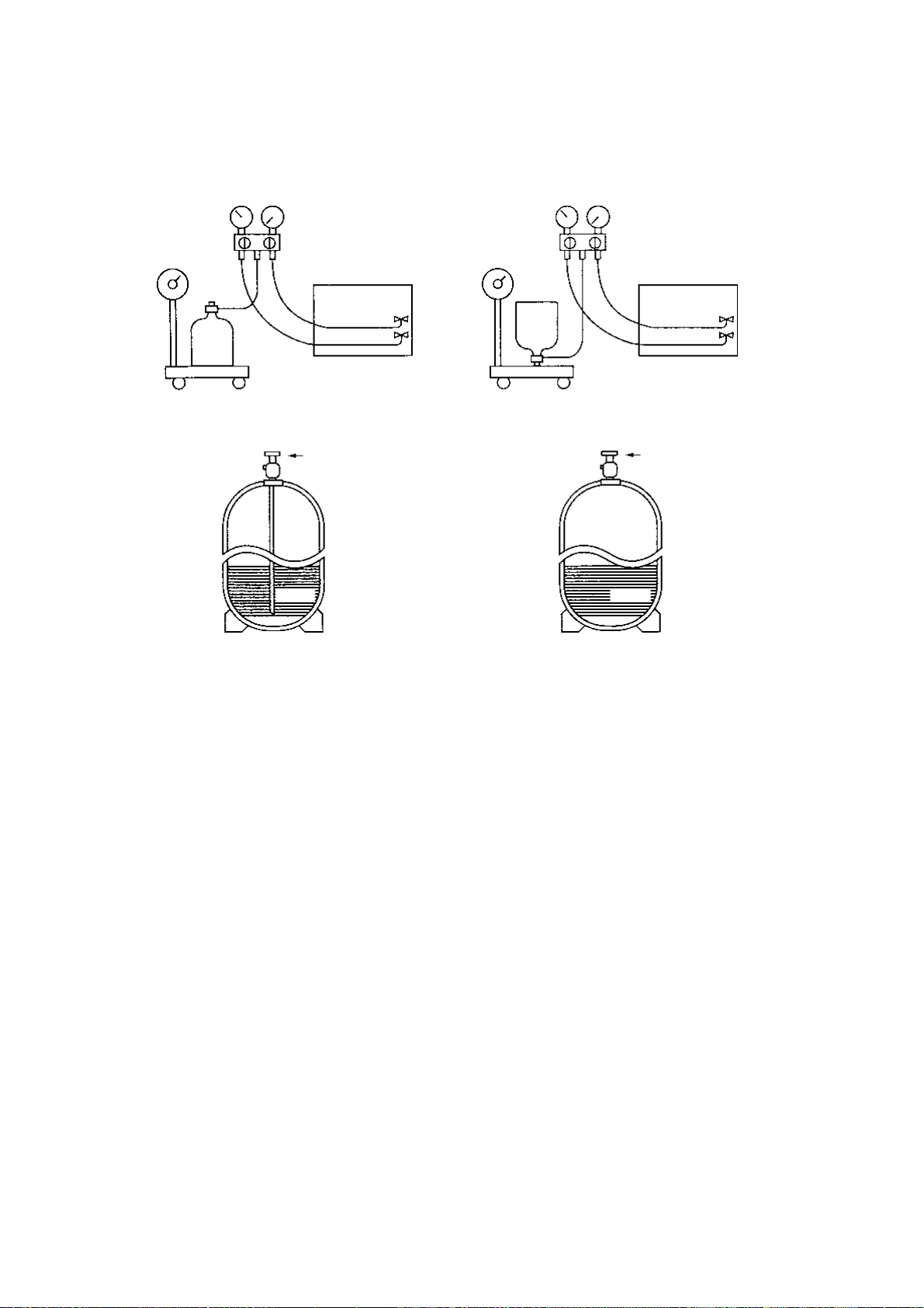
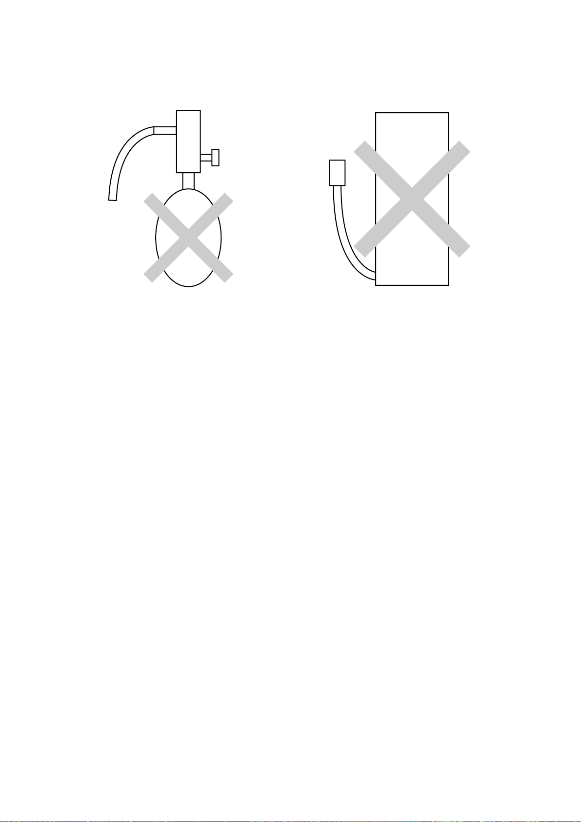
[6] Charging of Refrigerant
R407C must be in a liquid state when charging, because it is a non-azeotropic refrigerant.
For a cylinder with a syphon attached For a cylinder without a syphon attached
Cylin-
Cylin-
der
Cylinder color identification R407C-Gray Charged with liquid refrigerant
R410A-Pink
Valve
der
Valve
Liquid
Liquid
Reasons :
1. R407C is a mixture of 3 refrigerants, each with a different evaporation temperature. Therefore, if the equipment is
charged with R407C gas, then the refrigerant whose evaporation temperature is closest to the outside temperature is
charged first while the rest of refrigerants remain in the cylinder.
Note :
• In the case of a cylinder with a syphon, liquid R407C is charged without turning the cylinder up side down. Check the
type of cylinder before charging.
[7] Dryer
1. Replace the dryer when the refrigerant circuit is opened (Ex. Change the compressor, full gas leakage). Be sure to
replace the dryer with a CITY MULTI Series Y (For use with R407C).
If any other product is used, the unit will be damaged.
2. Opening the refrigerant circuit after changing to a new dryer is less than 1 hour. The replacement of the dryer should
be the last operation performed.
–8–
Page 11

22
2 COMPONENT OF EQUIPMENT
22
[1] Appearance of Components
Outdoor unit
• PURY-P400·500YMF-C
Fan motor
Heat exchanger(rear)
Propeller fan
Fan motor
Propeller fan
Heat exchanger(front)
4–way
valve
CV
block 1
SV block 1
CV block 2
SV block 2
Control box
4–way valveCS circuit
Drier
Compressor
P500 TYPEP400 TYPE
Accumulator
Compressor
Compressor
–9–
Page 12
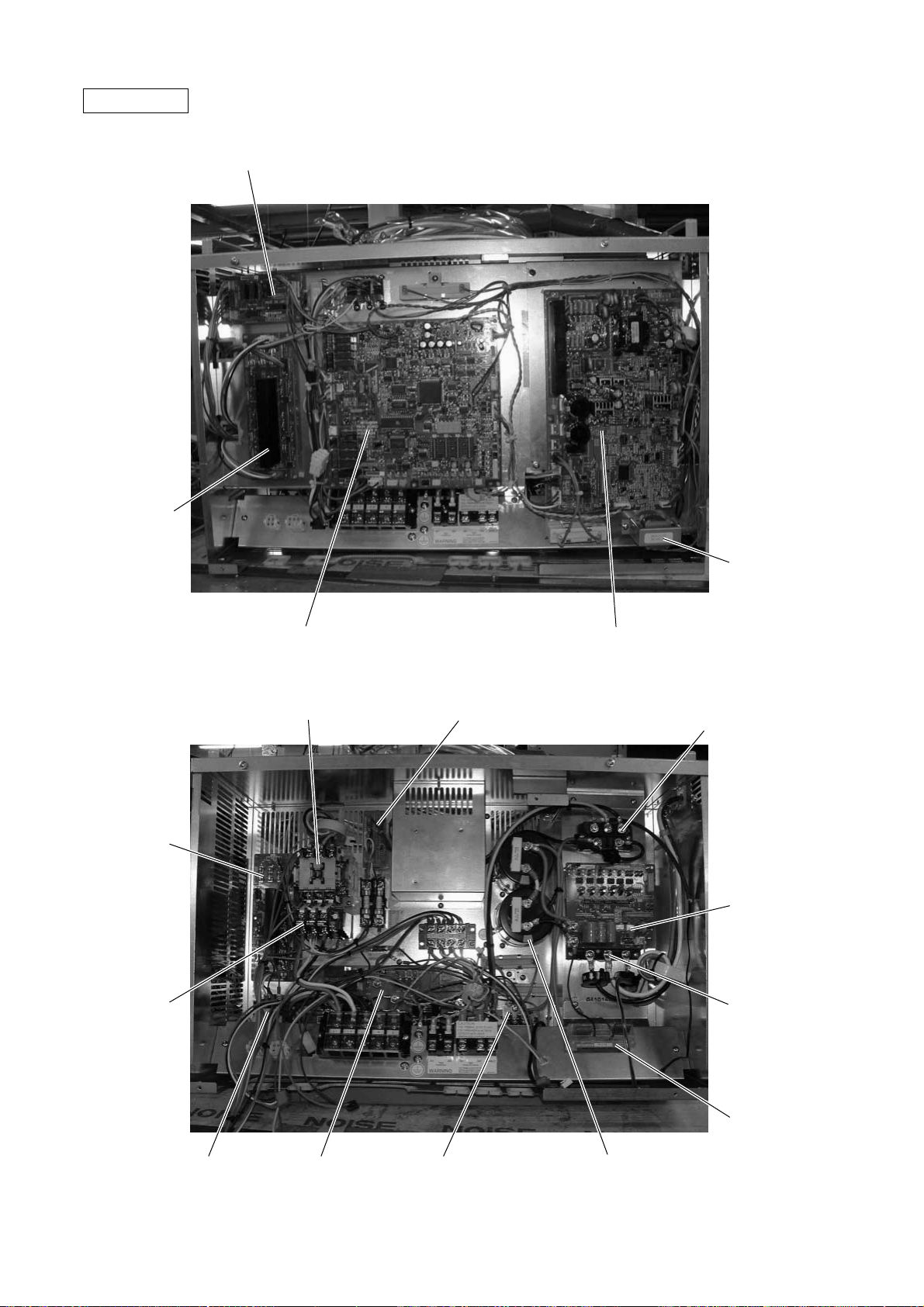
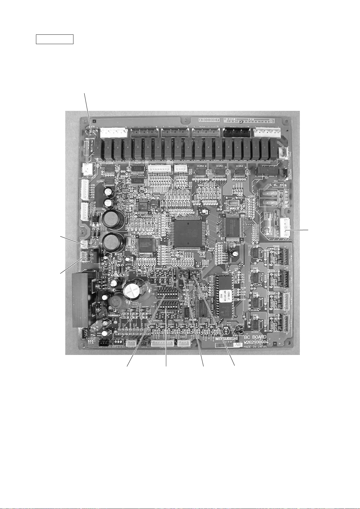
Controller Box
FANCON board
(for MF3)
RELAY board
FANCON board
(for MF2)
Overload relay
(51C2)
Magnetic contactor (52C2)
SNB board
Choke coil (L2)
INV boardMAIN board
Diode stack (DS)
G/A board
Inteligent Power
Module (IPM)
(52F)
Noise filter
(NP)
Y-C board
Magnetic contactor (52C1)Magnetic contactor
Capacitor (C2, C3)
(Smoothing capacitor)
–10–
Page 13
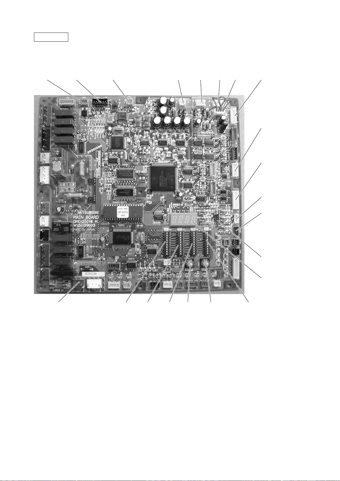
MAIN board
• PUHY / PURY
CNTR CNFC1
CNVCC4
Power source
for control(5V)
CNS1 CNS2
CN40
CN41
CNVCC3
Power Source
for control
1-2 30V
1-3 30V
4-6 12V
5-6 5V
CN51
Indication distance
3-4 Compressor
ON/OFF
3-5 Trouble
CNRS3
Serial transmission to
INV board
CN3D
CN20
Power supply
3 L1
1 N
SW3SW4 SW2 SWU2 SWU1
CN3S
CN3N
LD1
Service LED
SW1
–11–
Page 14
INV board
CNVDC
1-4
DC-560V
CN15V2
Power supply
for IPM control
CNR
CN52C
Control for
52C
CNFAN
Control
for MF1
CNAC2
Power
source
1 L2
3 N
5 G
SW1
CNRS2
Serial transmission
to MAIN board
CNVCC4
Power supply (5V)
CNL2
Choke coil
CNVCC2
Power supply
1-2 30V, 1-3 30V
4-6 12V, 5-6 5V
CNDR2
Out put to
G/A board
CNTH
CNACCT
–12–
Page 15
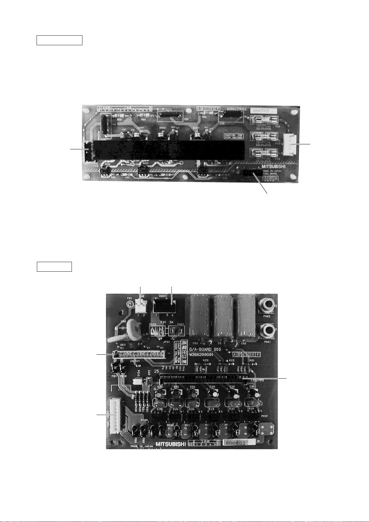
FANCON board
CNFAN
G/A board
CNPOW
CNFC2
CNE CNDC1
CN15V1
CNDR1
CNIPM1
–13–
Page 16
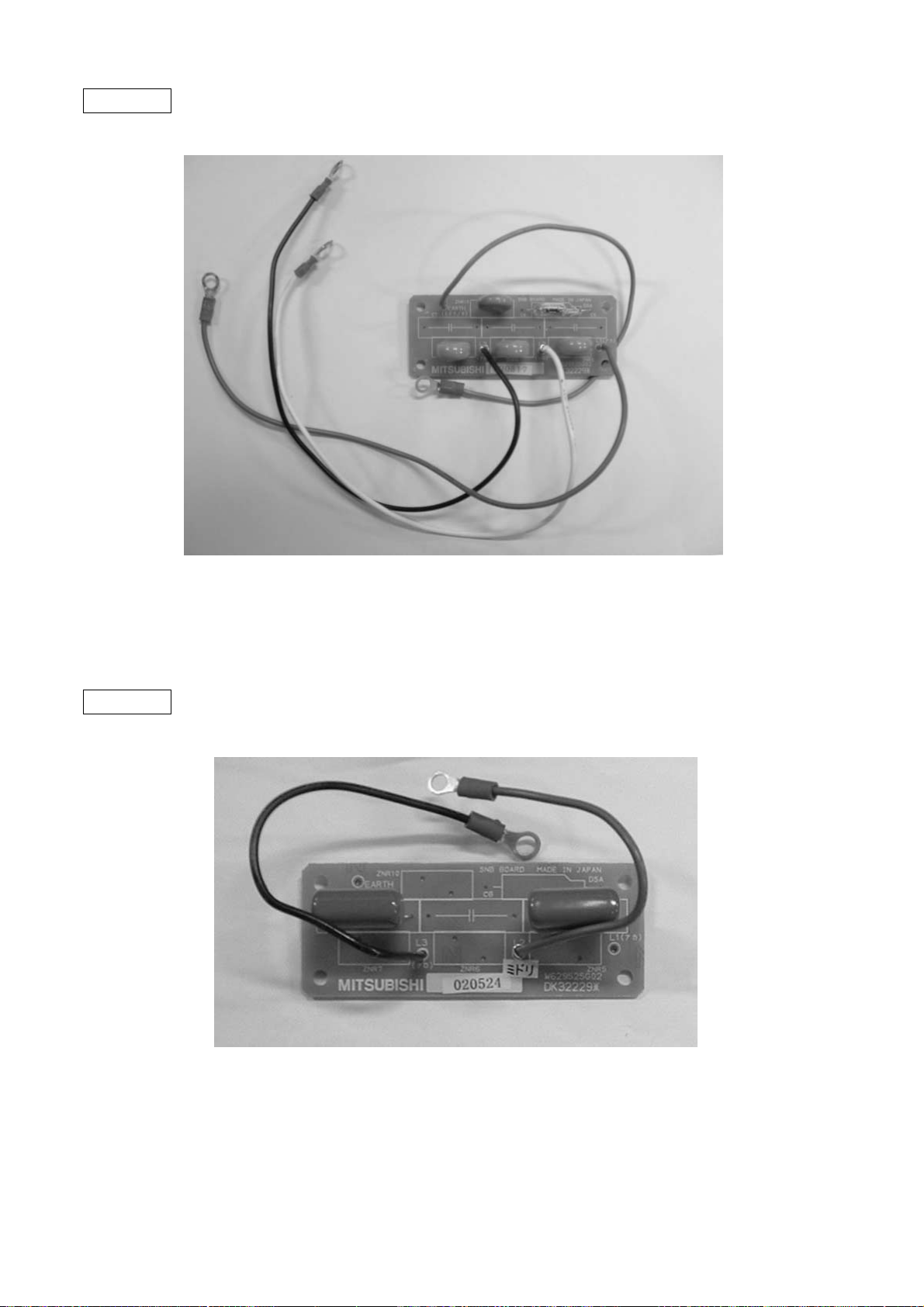
SNB board
Y -C board
–14–
Page 17
BC controller
CNTR
CN02
M-NET
transmission
CN03
CN12
Power
supply
1 EARTH
3 N
5 L
SW4 SW2 SW1SW5
–15–
Page 18
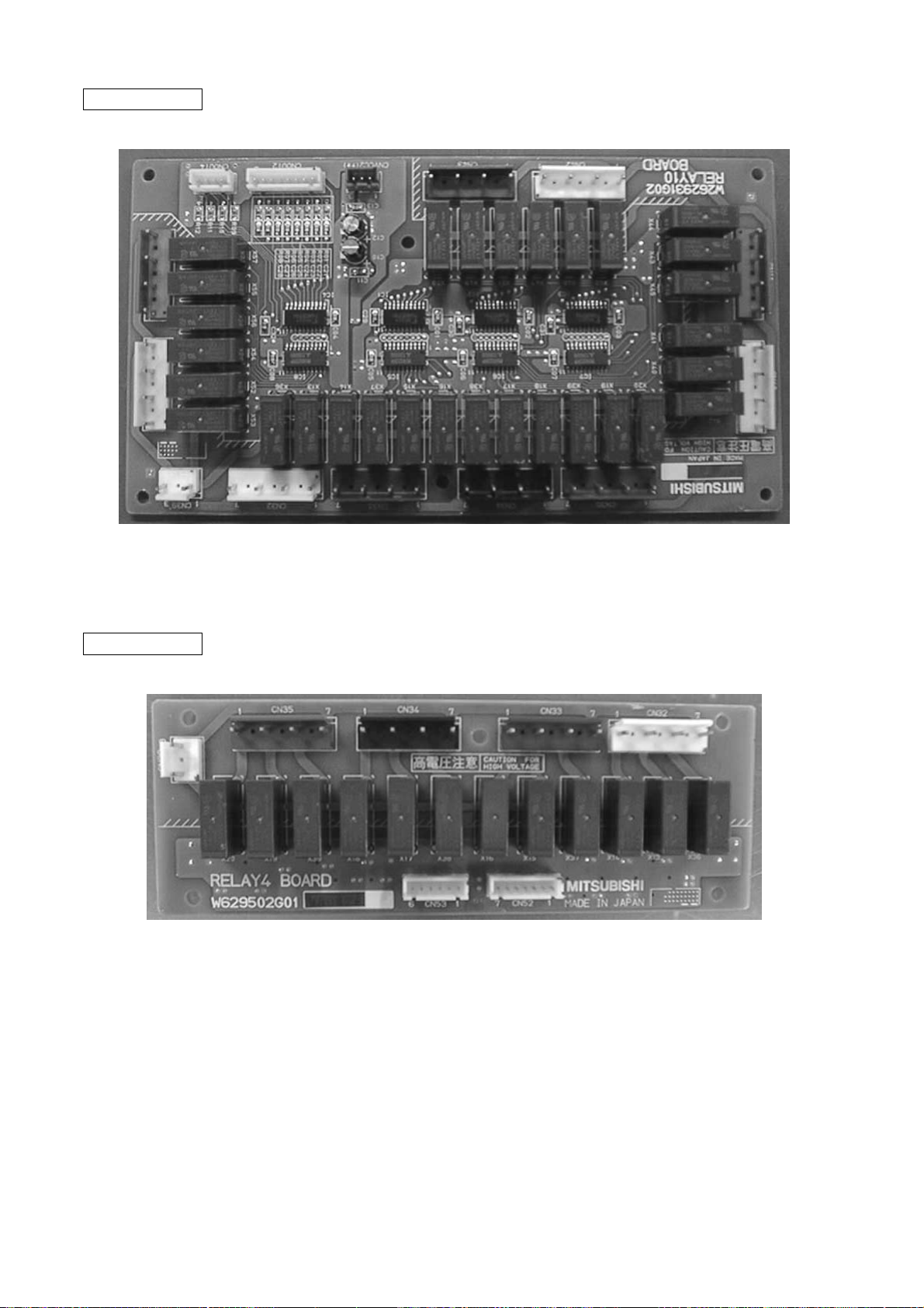
RELAY 10 board
RELA Y 4 board
–16–
Page 19
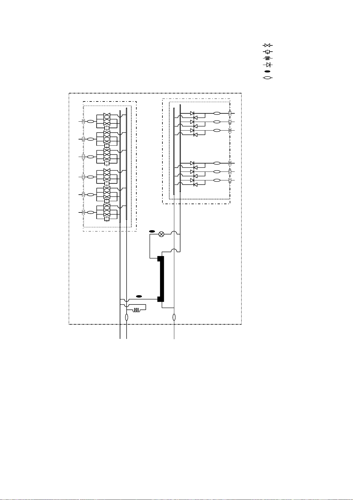
[2] Refrigerant Circuit Diagram and Thermal Sensor
PURY-P400, 500YMF-C
CV7b
CV5b
CV3b
CV2b
CV6b
BV1
ST1
BV2
TH5
SP : Service port
ACC : Accumulator
: Solenoid valve
: Orifice
: Capillary
: Check valve
: Thermal sensor
: Strainer
SV Block 2
SV8
SV7
HEXf4
HEXb2
SV Block 1
CJ2
SV5
SV3
SV6
SV4
CV7a
TH7
63LS
HEXf3
HEXb1
TH6
ST15
MA
HEXf2
CV4b
HEXf1
CV Block 2
ST14
ST13
ST12
ST11
CV5a
CV10a
CV9a
CV3a
CV2a
CV4a
CV8a
CV6a
Orifice
CV Block 1
21S4b
21S4a
SV4a
ST5
CJ1
ST2
SV6a
63HS
O/S
CP1
ST6
SV1
SV32
SV22
CP3a
CP3b
TH12
TH11
CV1b
CV1a
SA
63H2
63H1
–17–
Comp2
CJ3
SLEV
Comp1
ST9
ST3
TH3
ST4
TH4
ST8
CP2
TH9
Drier
CS Circuit
TH2
SV22, 32: P500 only
*
Page 20
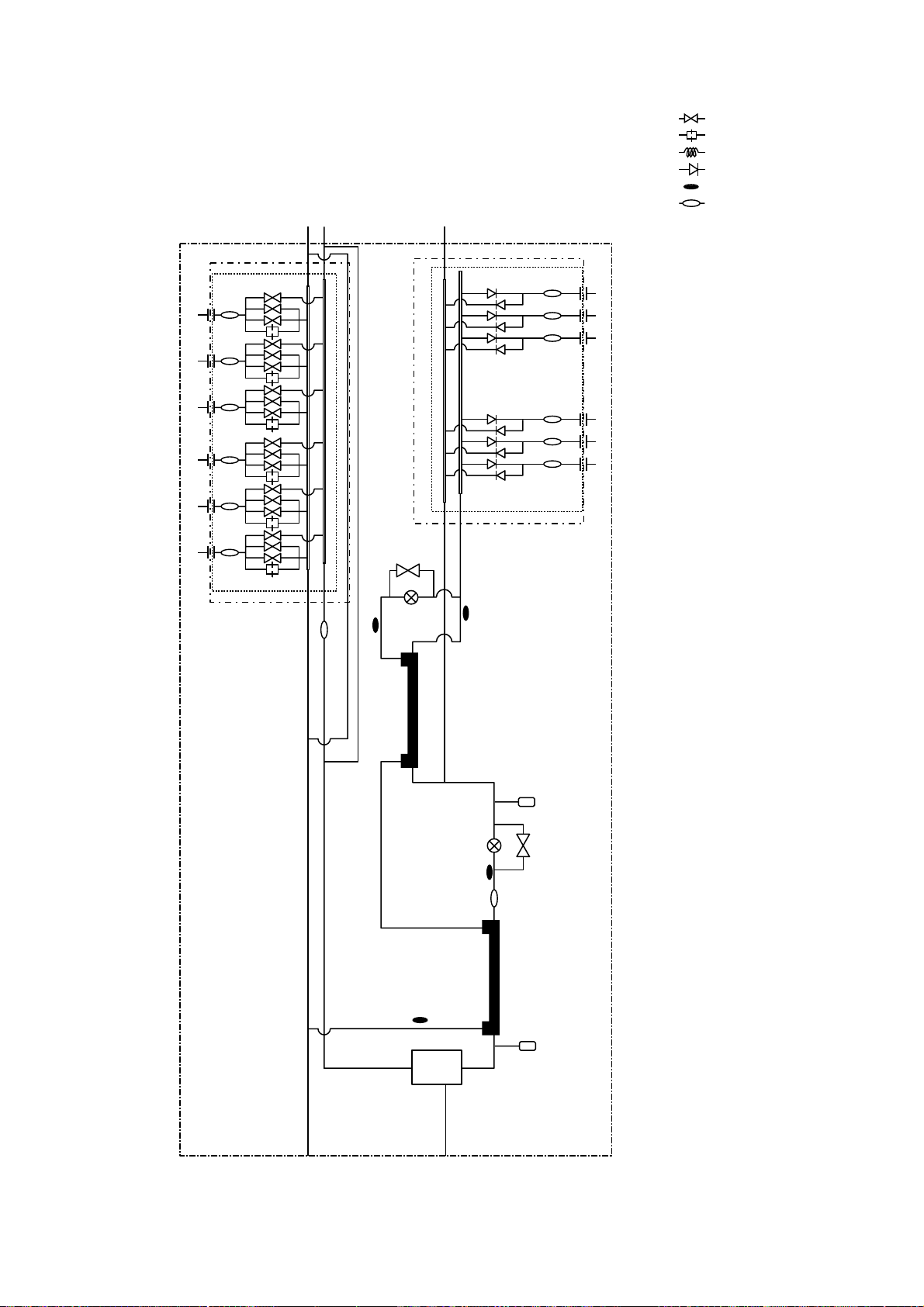
CMB-P108, 1010, 1013, 1016V-FA
: Solenoid valve
: Orifice
: Capillary
: Check valve
: Thermal sensor
: Strainer
Solenoid
valve block
TH15
SVM2
LEV3
TH12
TH16
LEV1
TH11
Check
valve block
PS3
SVM1
–18–
Gas/liquid
separator
PS1
Page 21
CMB-P108V-FB
: Solenoid valve
: Orifice
: Capillary
: Check valve
: Thermal sensor
: Strainer
Solenoid
valve block
TH22
CP
TH25
LEV3a
Check
valve block
–19–
Page 22
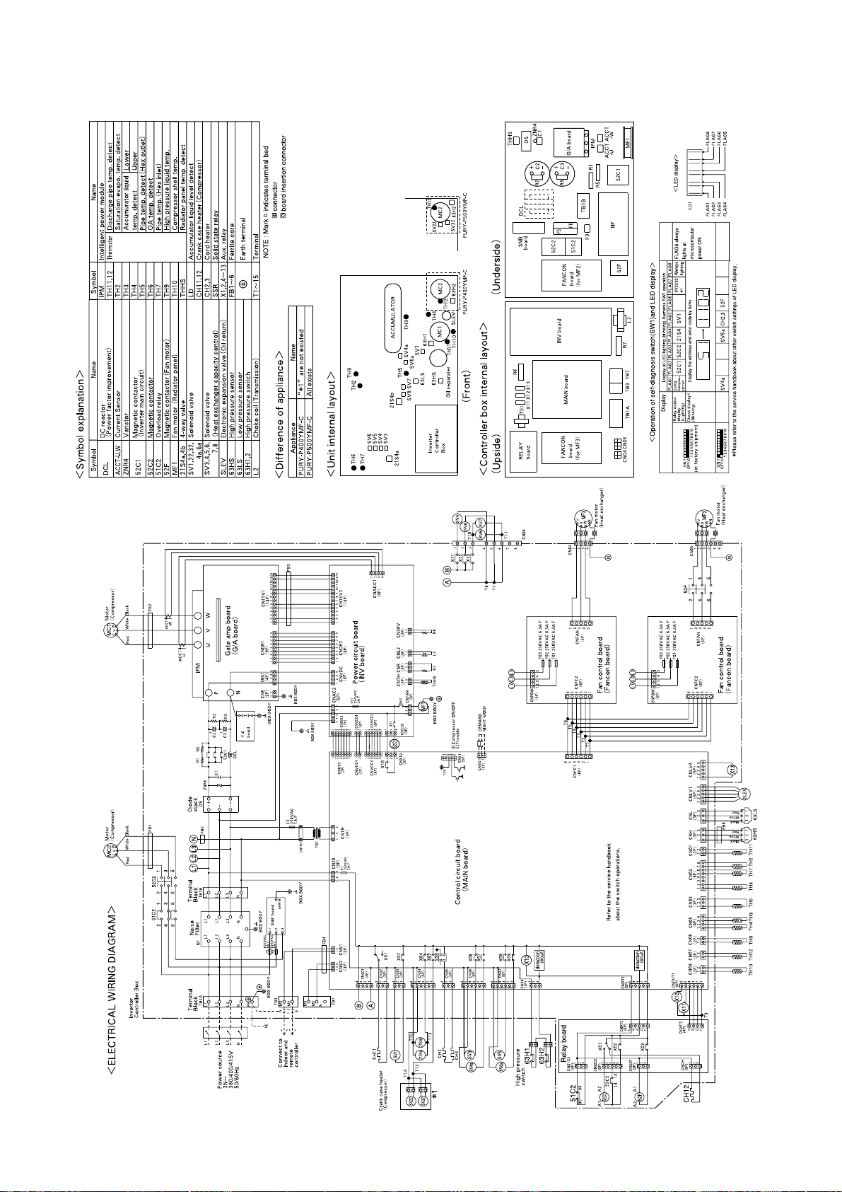
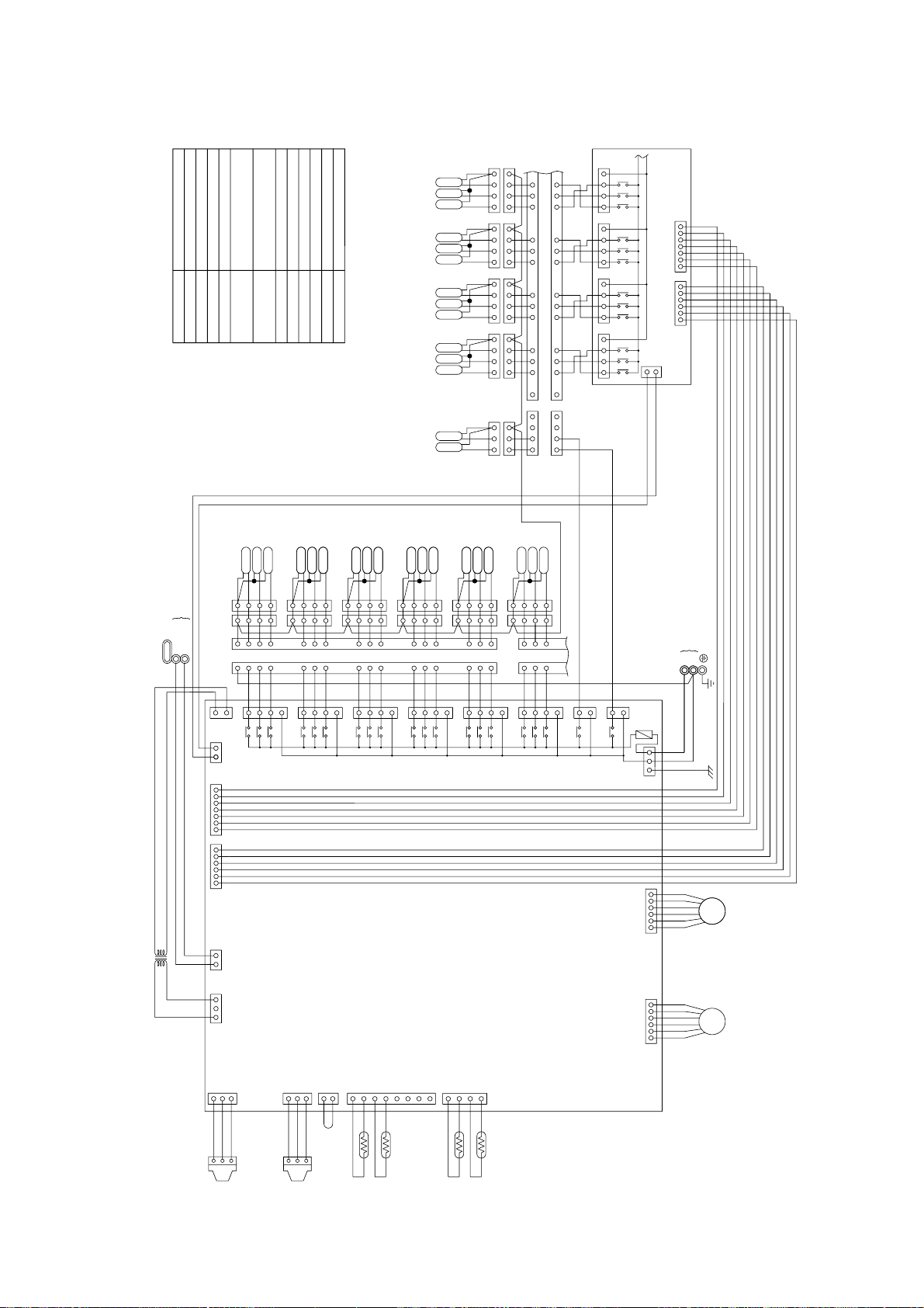
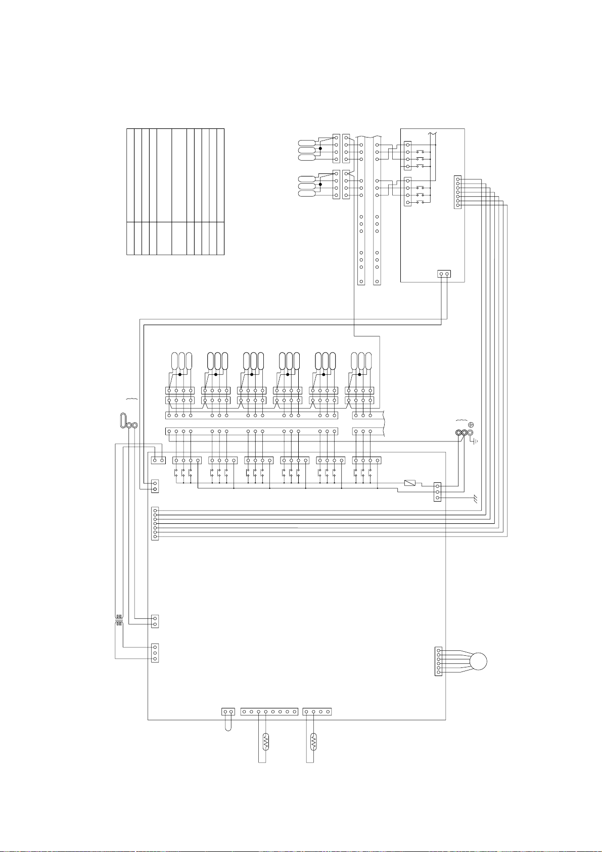
[3] Electrical Wiring Diagram
PURY-P400·500YMF-C
–20–
Page 23
5
1
2
34
4
1
2
3
1
2
3
1
2
3
SVM1
SVM2
131415
9
101112
5
6
78
4
4
5
6
87
9
12 11 10
15 14 13
16
16
1
2
3
4
1
2
3
4
1
2
3
4
1
2
3
4
1
2
3
4
1
2
3
4
1
2
3
4
1
2
3
4
SV7B
SV8B
SV9B
SV10B
SV7A
SV8A
SV9A
SV10A
SV7C
SV8C
SV9C
SV10C
SV1B
SV1A
SV1C
1
5
6
7
8
9
10
11
12
13
14
15
16
3
2
4
8
9
10
11
12
13
3
2
4
1
5
6
7
14
15
16
4
3
2
1
SV2C
SV2A
SV2B
SV3C
SV3A
SV3B
SV4C
SV4A
SV4B
SV5B
SV5A
SV5C
4
3
2
1
4
3
2
1
4
3
2
1
4
3
2
1
4
3
2
1
4
3
2
1
4
3
2
1
4
3
2
1
4
3
2
1
SV6B
SV6A
SV6C
1
2
3
4
1
2
3
4
33
2
1
2
1
X60
X21
CN46
CN36
3
1
3
1
Power source
L
N
~220V~240V 50/60Hz
Transmission line
Shield wire
CONT.board
CN38
1
3
1
CNTR
CN50CN51
7654321123456
CN02
CN12
13
7
5
3
1
7
5
3
1
7
5
3
1
7
5
3
1
7
5
3
1
7
5
3
1
3
TR
X2
X1
X30
X4
X3
X31
X6
X5
X32
X8
X7
X33
X10
X9
X34
X12
X11
X35
DC 30V
6
54
3
2
1
6
54
3
2
1
LEV3 LEV1
1
2
3
CNP1
1
2
3
CNP3
2
1
1
2
3
4
5
6
7
8
4
3
2
1
12321
CN03
CN13
CN10
CN11
CN07 CN05
TH11
TH12
TH15
TH16
PS1
PS3
22V
TB02
M2
M1
CN26
CN27
CN28
CN29
CN30
CN31
TB01
220~240V
LEV1
7654321123456
CN35
TB01
RELAY4 Board
CN32
CN33
CN34
CN39
3
1
X14
X13
X36
X37
X15
X16
X18
X17
X38
X39
X19
X20
CN52CN53
57317531753175133 3
F01
250VAC
6.3A F
T8T9
T7
T10
T1
T5
T4
T3
T2
T6
PE
3
2
1
3
2
1
EARTH
Fuse AC250V 6.3A F
F01
Terminal
T1 ~ 10
SVM1, 2
Solenoid valve
TB02
TB01
Terminal block
(for Transmission)
Solenoid valve
Solenoid valve
Solenoid valve
Terminal block
(for power source)
Pressure sensor
Expansion valve
Thermistor sensor
Transformer
NameSymbol
SV1 ~ 10A
SV1 ~ 10B
SV1 ~ 10C
TR
TH11, 12, 15, 16
LEV1, 3
PS1, 3
Note1:TB02 is terminal block for transmission.
Never connect power line to it.
<
Symbol explanation
>
CMB-P108·1010V-FA
–21–
Page 24
3
2
1
Power source
L
TB01TB01
N
~220V~240V 50/60Hz
1
2
3
SVM2
SVM1
1
3
2
8
8
9
9
10
10
11
11
12
12
13
13
3
2
4
4
1
5
5
6
6
7
7
14
14
15
15
16
16
4
3
2
1
4
3
2
1
4
3
2
1
4
3
2
1
4
3
2
1
4
3
2
1
4
3
2
1
4
3
2
1
4
3
2
1
4
3
2
1
1
2
3
4
1
2
3
4
3
3
4
4
2
2
1
1
SV11B
SV11A
SV11C
SV16C
SV16A
SV16B
SV15C
SV15A
SV15B
SV14C
SV14A
SV14B
SV13C
SV13A
SV13B
SV12C
SV12A
SV12B
131415
9
101112
5
6
78
4
4
5
6
87
9
12 11 10
15 14 13
16
16
1
2
3
4
1
2
3
4
1
2
3
4
1
2
3
4
1
2
3
4
1
2
3
4
1
2
3
4
1
2
3
4
SV7B
SV8B
SV9B
SV10B
SV7A
SV8A
SV9A
SV10A
SV7C
SV8C
SV9C
SV10C
SV1B
SV1A
SV1C
1
5
6
7
8
9
10
11
12
13
14
15
16
3
2
4
8
9
10
11
12
13
3
2
4
1
5
6
7
14
15
16
4
3
2
1
SV2C
SV2A
SV2B
SV3C
SV3A
SV3B
SV4C
SV4A
SV4B
SV5B
SV5A
SV5C
4
3
2
1
4
3
2
1
4
3
2
1
4
3
2
1
4
3
2
1
4
3
2
1
4
3
2
1
4
3
2
1
4
3
2
1
SV6B
SV6A
SV6C
1
2
3
4
1
2
3
4
33
2
1
2
1
3
1
3
1
CN36
CN46
X21
X60
Transmission line
Shield wire
1
2
3
8
7
6
5
4
3
2
1
4
CNTR
1
3
220~240V
CN35
CN31
CN30
CN29
CN28
CN27
CN26
CN38
M1
M2
TB02
TR
22V
PS3
PS1
TH16
TH15
TH12
TH11
CN32
7531
CN33
CN34
33
CN05CN07
CN11
CN10
CN13
CN02
CN03
12321
1
2
3
4
8
7
6
5
4
3
2
1
1
2
CNP3
3
2
1
CNP1
3
2
1
LEV1LEV3
1
2
3
45
6
1
2
3
45
6
DC 30V
X35
X11
X12
X34
X9
X10
X33
X7
X8
X32
X5
X6
X31
X3
X4
X30
X1
X2
X14
X13
X36
X37
X15
X16
21
CNVCC1
3
X38
X39
X17
X19
X18
X20
X45
X42
X43
X40
X44
X41
CN40
CN41
CNOUT4
CNOUT2
4
1
2
3
4
5
6
7
8
3
2
1
X48
X51
X47
X46
X50
X49
CN43
CN42
CN44
CN45
X55
X56
X52
X53
X57
X54
3
CNVCC2
12
31
753175317531
1
3
5
7
7
5
3
1
7
5
3
1
7
5
3
1
7
5
3
1
7
5
3
1
7
5
3
1
7
5
3
1
7
5
3
1
7
5
3
1
7
5
3
1
7
5
3
1
CNOUT1
CNOUT3
CN12
53
1
31
CN39
CONT.board
RELAY10 board
F01
250VAC
6.3A F
PE
EARTH
T16
T15
T14
T13
T12
T11
T8T9
T7
T10
T1
T5
T4
T3
T2
T6
3
2
1
3
2
1
Terminal
T1
~
16
Solenoid valve
SVM1, 2
PS1, 3
SV1
~
16A
SV1
~
16B
SV1
~
16C
Fuse AC250V 6.3A FF01
Symbol
Name
Pressure sensor
Terminal block
(for power source)
Solenoid valve
Solenoid valve
Solenoid valve
Terminal block
(for Transmission)
TB01
TB02
<
Symbol explanation
>
Transformer
Thermistor sensor
Expansion valve
TR
LEV1, 3
TH11, 12, 15, 16
Note1:TB02 is terminal block for transmission.
Never connect power line to it.
CMB-P1013·1016V-FA
–22–
Page 25
131415
9
101112
5
6
78
4
4
5
6
87
9
12 11 10
15 14 13
16
16
1
2
3
4
2
3
4
1
2
3
4
1
2
3
4
SV7B
SV8B
SV7A
SV8A
SV7C
SV8C
1
SV1B
SV1A
SV1C
1
5
6
7
8
9
10
11
12
13
14
15
16
3
2
4
8
9
10
11
12
13
3
2
4
1
5
6
7
14
15
16
4
3
2
1
SV2C
SV2A
SV2B
SV3C
SV3A
SV3B
SV4C
SV4A
SV4B
SV5B
SV5A
SV5C
4
3
2
1
4
3
2
1
4
3
2
1
4
3
2
1
4
3
2
1
4
3
2
1
4
3
2
1
4
3
2
1
4
3
2
1
SV6B
SV6A
SV6C
1
2
3
4
1
2
3
4
33
2
1
2
1
Power source
L
N
~220V~240V 50/60Hz
Transmission line
Shield wire
CONT.board
CN38
1
3
1
CNTR
CN50
7654321
CN02
CN12
1
53
7
5
3
1
7
5
3
1
7
5
3
1
7
5
3
1
7
5
3
1
7
5
3
1
3
TR
X2
X1
X30
X4
X3
X31
X6
X5
X32
X8
X7
X33
X10
X9
X34
X12
X11
X35
DC 30V
6
54
3
2
1
LEV3
2
1
1
2
3
4
5
6
7
8
4
3
2
1
12321
CN03
CN13
CN10
CN11
CN07
TH12
TH15
22V
TB02
M2
M1
CN26
CN27
CN28
CN29
CN30
CN31
TB01
220~240V
7654321
TB01
RELAY4 Board
CN32
CN33
CN39
3
1
X14
X13
X36
X37
X15
X16
CN52
75317513
F01
250VAC
6.3A F
T8
T7
T1
T5
T4
T3
T2
T6
PE
EARTH
F01
Fuse AC250V 6.3A F
Terminal
T1
~
8
TB02
TB01
Terminal block
(for Transmission)
Solenoid valve
Solenoid valve
Solenoid valve
Terminal block
(for power source)
Expansion valve
Thermistor sensor
Transformer
Name
Symbol
SV1
~
8A
SV1
~
8B
SV1
~
8C
TR
TH12, 15
LEV3
Note1:TB02 is terminal block for transmission.
Never connect power line to it.
<
Symbol explanation
>
CMB-P108V-FB
–23–
Page 26
[4] Standard Operation Data
1 Cooling operation
Items
Ambient temp.
Indoor unit
Condition
Piping
Indoor unit fan notch
Refrigerant volume
Total current
Voltage
Outdoor unit
Indoor unit
Indoor
Outdoor
Quantity
Quantity in operation
Model
Main pipe
Branch pipe
Total piping length
Outdoor unit
DB/WB
Set
-
m
-
kg
A
V
PURY-P400YMF-C PURY-P500YMF-C
27.0/19 27.0/19
35.0/24.0 35.0/24.0
55
55
100 100 100 50 50 125 125 125 100 25
55
10 10 10 10 10 10 10 10 10 10
55 55
Hi Hi Hi Hi Hi Hi Hi Hi Hi Hi
27.1 29.2
27.6/26.2/25.2 34.6/32.8/31.7
380/400/415 380/400/415
360 360 360 340 340 410 410 410 360 280
BC controller (1, 3)
LEV opening
Oil return (SLEV)
High pressure/Low pressure
(after O/S) (before MA)
BC
Pressure
controller
Outdoor
unit
Sectional temperature
High/Intermediate
Discharge (TH11/TH12)
Heat exchanger outlet (TH5)
Accumulator
Suction (Comp) (No.1/No.2)
Low pressure saturation
temperature (TH2)
Liquid level
Shell bottom (Comp No.1/No.2)
Inlet
Outlet
Upper (TH4)
Lower (TH3)
Pulse
kg/cm2G
(MPa)
°C
2000 300 2000 350
200 344
21.5/4.4 21.5/4.3
(2.11/0.43) (2.11/0.42)
20.5/20.5 20.5/20.5
(2.01/2.01) (2.01/2.01)
92/102 97/102
42
45
67
6/12 12/12
1
30
1
60/51 65/50
Indoor
unit
CS circuit (TH9)
Circulating configuration (αOC)
LEV inlet
Heat exchanger outlet
16
0.23
26
12
–24–
Page 27
2 Heating operation
Items
Outdoor unit
PURY-P400YMF-C PURY-P500YMF-C
Ambient temp.
Indoor unit
Condition
Piping
Indoor unit fan notch
Refrigerant volume
Total current
Voltage
Outdoor unit
Indoor unit
BC controller (1, 3)
Oil return (SLEV)
LEV opening
Indoor
Outdoor
Quantity
Quantity in operation
Model
Main pipe
Branch pipe
Total piping length
DB/WB
Set
-
m
-
kg
A
V
Pulse
20.0/- 20.0/-
7.0/6.0 7.0/6.0
55
55
100 100 100 50 50 125 125 125 100 25
55
10 10 10 10 10 10 10 10 10 10
55 55
Hi Hi Hi Hi Hi Hi Hi Hi Hi Hi
27.1 29.2
25.6/24.3/23.4 32.1/30.5/29.4
380/400/415 380/400/415
600 600 600 450 450 650 650 650 600 350
60 1400 60 1600
122
High pressure/Low pressure
(after O/S) (before MA)
BC
Pressure
controller
Outdoor
unit
Sectional temperature
High/Intermediate
Discharge (TH11/TH12)
Heat exchanger inlet (TH5)
Accumulator
Suction (Comp) (No.1/No.2)
Low pressure saturation
temperature (TH2)
Liquid level
Shell bottom (Comp No.1/No.2)
CS circuit (TH9)
Circulating configuration (αOC)
Inlet
Outlet
Upper (TH4)
Lower (TH3)
kg/cm2G
(MPa)
°C
21.5/3.6 21.5/3.2
(2.11/0.35) (2.11/0.31)
20.5/17.5 20.5/17.5
(2.01/1.72) (2.01/1.72)
88/93 88/93
– 3 – 1
– 6 – 7
– 6 – 7
– 5/2 – 5/0
– 10
30
– 6
43/45 40/33
5
0.28
Indoor
unit
Heat exchanger inlet
LEV inlet
81
34
–25–
Page 28
[5] Function of Dip SW and Rotary SW
(1) Outdoor unit
PURY-P400·500YMF-C.
1 Variable capacity unit
MAIN board
Switch Function
SWU 1 ~ 2
SW1
SW2
SW3
SW4
Unit Address Setting
For self diagnosis/
1 ~ 8
operation monitoring
9 ~ 10
Centralized Control
1
Switch
Deletion of connection
2
information.
Deletion of error history.
3
• Adjustment of Refriger-
4
ant Volume
• Ignore liquid level errors
5
6
Forced defrosting
7
8
Reset of the time the CS
9
circuit is closed.
10
SW3-2 Function Valid/
1
Invalid
Indoor Unit Test Operation
2
Defrosting start tempera-
3
ture .
Defrosting end tempera-
4
ture.
Target low-pressure
5
change
Pump Down Function
6
Target high-pressure
7
change
8
9
10
SW4-2 Function valid/
1
Invalid
Configuration compensa-
2
tion value
3
4
5
6
7
8
9
10
Models
-
-
-
-
-
-
-
-
-
-
-
-
-
-
-
Function According to Switch Operation Switch Set Timing
When Off When On When Off When On
Set on 51 ~ 100 with the rotary switch.*2
Centralized control not
connected.
Storing of refrigeration
system connection
information.
Store IC•OC error history.
Ordinary control
Ordinary control
When the CS circuit is
closed, that time is totaled.
SW3-2 Function Invalid
Stop all indoor units.
– 8°C
7°C
Ordinary control
Ordinary control
Ordinary control
Model 400
SW4-2 Function invalid
Changes as shown below by on → off change
0 %→3 %→6 %→9 %→12 %→ – 6 %→ – 3 %→0 %
Before power is turned on.
Refer to LED monitor display on the outdoor board.
Centralized control
connected.
Deletion of refrigeration
system connection
information.
Erase IC•OC error history .
• Refrigerant volume
adjustment operation.
• Ignore liquid level errors
-
Start forced defrosting.
Timer Reset
SW3-2 Function Valid
All indoor units test run
ON.
2deg lower than normal
Pump Down Operation
High pressure / 1.5 ~ 2.5 K
higher than normal
-
-
SW4-2 Function valid
-
-
-
-
-
-
-
-
-
-
-
-
-
– 10°C
12°C
-
-
Model 500
-
-
-
-
-
-
-
-
Before power is turned on.
Before power is turned on.
During normal operation when
power is on.
During normal
operation when
power is on.
During normal
operation when
power is on.
During normal operation when
power is on.
During normal operation when
power is on.
When SW3-1 is ON after power is
turned on.
During normal operation when
power is on.
During normal operation when
power is on. (Except during
defrosting)
During normal operation when
power is on.
While the compressor is stopped.
During normal operation when
power is on.
When switching on the power.
When switching on the power.
When SW4-1 is ON
-
Invalid 2 hours
after compressor
starts.
-
10 minutes or
more after
compressor
starts.
-
-
-
-
-
-
-
-
-
-
-
-
Note 1: Factory setting is SWU 1 to 2 = 00, SW3 - 10 = set by model. All other switches are set to OFF.
Note 2: If the address is set from 01 to 50, it automatically becomes 100.
–26–
Page 29
(2) Indoor unit
DIP SW1, 3
Switch SW name
Room temp. sensor position
1
Clogged filter detect.
2
Filter duration
3
OA intake
4
Remote display select.
5
SW1
SW3
Humidifier control
6
Heating thermo. OFF airflow
7
Heating thermo. OFF airflow
8
Power failure automatic
9
return
Power source start/stop
10
Model selection
1
2
Louver
3
Vane
4
Vane swing function
5
Vane horizontal angle
6
Vane angle set for cooling
Cooling capacity saving
for PKFY-P. VAM,
effective/ineffective
7
8
Heating 4deg up
9
10
Operation by SW
OFF ON OFF ON
Indoor unit inlet
None
100h
Ineffective
Fan output display
At stationary heating
Very low speed
SW1-7 setting
Ineffective
Ineffective
Heat pump
None
None
None
1st setting
Down blow B, C
–
–
Effective
–
–
–
–
Built in remote controller
Provided
2500h
Effective
Thermo. ON signal display
Always at heat.
Low speed
Set airflow
Effective
Effective
Cool.only
Provided
Provided
Provided
2nd setting
Horizontal
–
Ineffective
–
–
Switch set timing
At unit stopping
(at remote
controller OFF)
Remarks
Always ineffective for PKFY-P.VAM
Not provided for PKFY-P.VAM
Provided for PLFY-P.VGM (ON) setting
Always down blow B,C for PKFY-P.VAM
Horizontal (ON) setting for PLFY-P.VLMD
Ineffective (ON) setting for floor
standing
Note 1: The shaded part indicates the setting at factory shipment. (For the SW not being shaded, refer to the
table below.)
Switch
SW1
SW3
Model
3
6
7
3
4
6
8
VBM-A
OFF
OFF
ON
OFF
PLFY-P
VLMD-A
ON
OFF
ON
OFFONON
VKM-A
VML-A VMH-A
OFF ON
ON
OFF
PEFY-P
20~80VMM-A
OFF
ON
OFF ON
PDFY-P
100~140VMM-A
OFF
OFF
OFF
VM-A
ON
PFFY-P PCFY-P
VLRM-A, VLEM-A
OFF
OFF
ON OFF
PKFY-P
VGM-AONVAM-A VGM-A
OFF
OFF
ON
ON OFF ON
Note 2: The DipSW setting is only effective during unit stopping (remote controller OFF) for SW1, 2, 3 and 4 commonly
and the power source is not required to reset.)
3: When both SW1-7 and SW1-8 are being set to ON, the fan stops at the heating thermostat of OFF.
Setting of DIP SW2
Model P20 P25 P32 P40 P50 P63
Capacity (model name) code
SW2 setting
45 681013
ON
OFF
OFF
ON
OFF
ON
OFF
ON
OFF
ON
OFF
ON
Model P71 P80 P100 P125 P140 P200 P250
Capacity (model name) code
SW2 setting
14 16 20 25 28 40 50
ON
OFF
OFF
ON
OFF
ON
OFF
ON
OFF
ON
OFF
ON
OFF
ON
–27–
Page 30
Setting of DIP SW4 Setting of DIP SW5
Model Circuit board used
PMFY-P-VBM-A
PLFY-P-VLMD-A
PDFY-P20 ~ 80VM-A
PLFY-P40 ~ 63VKM-A
PLFY-P80 ~ 125VKM-A
PCFY-P-VGM-A
PKFY-P-VGM-A
PKFY-P-VAM-A
PEFY-P20 ~ 80VMM-A
PFFY -P-VLEM-A, P-VLRM-A
PEFY-P20 ~ 32VML-A
PEFY-P40 ~ 140VMH-A
PEHY-P200·250VMH-A
PDFY-P100·125VM-A
PEFY-P100 ~ 140VMM-A
Phase control
Relay selection
1234
ON OFF ON OFF
––––
ON OFF ON OFF
OFF OFF OFF ON
ON OFF OFF ON
OFF ON OFF ON
OFF OFF ON ON
––––
ON ON OFF OFF
OFF OFF OFF –
ON ON ON –
OFF OFF OFF –
ON OFF OFF –
OFF OFF ON –
ON ON ON OFF
SW4
220V
240V
Switch Function Operation by switch Switch set timing
(PLFY-P-VKM-A) (PCFY-P-VGM-A)
Ceiling height
3 3.5 m
2 2.8 m
1 2.3 m
Always after powering
SWA
Ceiling height setting
3
2
1
*The ceiling
height is
changed by
SWB setting.
3
2
1
SWA
SWA
SWB
SWC
External static
pressure setting
For options
Setting of air outlet opening
Airflow control
(PDFY-P20 ~ 80VM-A, PEFY-P20 ~ 80VMM-A)
3
2
1
*
For other models, change the setting of static pressure by replacing the connector.
100Pa
50Pa
30Pa
(PLFY-P-VLMD-A)
3
*As this switch is used by interlocking with SWC,
2
1
(PLFY-P-VKM-A)
refer to the item of SWC for detail.
2-way
3-way
4-way
SWA
SWB
123
2-way 3.5 m 3.8 m 3.8 m
3-way 3.0 m 3.3 m 3.5 m
4-way 2.7 m 3.0 m 3.5 m
(PLFY-P-VKM-A, PCFY-P-VGM-A, PKFY-P-VGM-A, PDFY-P-VM-A)
Option
Standard
*Set to the option to install the high efficiency
filter
Always after powering
Always after powering
Always after powering
Always after powering
–28–
Page 31

33
3 TEST RUN
33
[1] Before Test Run
(1) Check points before test run
1 Neither refrigerant leak nor loose power source/ transmission lines should be found.
2 Confirm that the resistance between the power source terminal block and the ground exceeds 2MΩ by measur-
ing it with a DC 500 V megger. Do not run if it is lower than 2MΩ.
Note: Never apply the megger to the MAIN board. If applied, the MAIN board will be broken.
3 Confirm that the Ball valve at gas and liquid, oil balance sides are fully opened.
Note: Certainly close the cap.
4 Be sure that the crankcase heater has been powered by turning the main power source on at least 12 hours
before starting the test run. The shorter powering time causes compressor trouble.
5 If any of the power supply wires (L1, L2, L3, N,
Please exercise caution.
6 A transmission booster (RP) is required when the number of connected indoor unit models in a cooling system
exceeds the number of models specified in the chart below.
Note: The maximum number of units that can be controlled is determined by the indoor unit model, the type of
remote controller and their capabilities.
.) are mistakenly connected, it is possible to damage the unit.
Remote controller type
(*1)
Capability of the
connected indoor units
The number of indoor units and the total number of remote controllers is displayed within the parenthesis ( ).
(*1) If even one unit that is higher than 200 exists in the cooling system, the maximum capacity will be “200 or
higher”.
* Please refer to the installation manual for more details.
* Before turning power on to the outdoor unit, first turn on the transmission booster. (If the outdoor unit are mistakenly
turned on first, turn on the transmission booster and then reset the outdoor unit power.)
(2) Caution at inverter check
Because the inverter power portion in outdoor unit electrical part box have a lot of high voltage portion, be sure to follow
the instructions shown below.
1
During energizing power source, never touch inverter power portion because high voltage (approx. 580 V) is
applied to inverter power portion.
Number of connected indoor units that
can be connected without a RP.
200 or lower
200 or higher
Remote controller PAR-F 25MA
Prior to Ver. E After Ver. F
16 (32) 20 (40)
16 (32) 16 (32)
2
When checking,
1
2
3
Shut off main power source, and check it with tester, etc.
Allow 10 minutes after shutting off main power source.
Open the MAIN board mounting panel, and check whether voltage of both ends of electrolytic capacitor is
20 V or less.
–29–
Page 32

(3) Check points for test run when mounting options
Built-in optional parts Content of test run Check point Result
Mounting of drain
water lifting-up
mechanism
Release connector of pump circuit,
1
check error detection by pouring water
into drain pan water inlet.
Local remote controller displays code No.
“2503”, and the mechanism stops.
No overflow from drain pan.
After that, connect connector of
2
circuit.
Check pump operations and drainage
3
status in cooling (test run) mode.
Mounting of permeable film humidifier
(4) Attention for mounting drain water lifting-up mechanism
Work Content of test run Check point Result
Disassembling and
assembling of drain
water lifting-up
mechanism
Check humidifier operations and
water supply status in heating (test
run) mode.
Lead wire from control box not
1
damaged.
Rubber cap properly inserted to drain
2
water outlet of drain pan?
Insulation pipe of gas and liquid pipes
3
dealt with as shown in the right
figure?
Drain water comes out by operations of
drain pump.
Sound of pump operations is heard, and
drain water comes out.
No water leak from connecting portions
of each water piping.
Water is supplied to water supply tank,
and float switch is operating.
Insulation pipe
Mounting of float
switch
Electric wiring
Drain pan and piping cover mounted
4
without gap?
Drain pan hooked on cut projection of
5
the mechanism?
Float switch installed without contacting
with drain pan?
No mistakes in wiring?
1
Connectors connected securely and
2
tightly?
No tension on lead wire when sliding
3
control box?
No gap
Float switch moves smoothly.
1
Float switch is mounted on mount-
2
ing board straight without deformation.
Float switch does not contact with
3
copper pipe.
Wiring procedure is exactly followed.
Connector portion is tightly hooked.
–30–
Page 33

(5) Check points for system structure
In the case of the PURY-P400·500 YMF-C
Check points from installation work to test run.
Classification Portion Check item Trouble
Installation
and piping
Power source
wiring
Instruction for selecting combination of outdoor unit, and
1
indoor unit followed? (Maximum number of indoor units
which can be connected, connecting model name, and
total capacity.)
2
Follow limitation of refrigerant piping length? For example, 100 m or less (total length: 220 m) at the farthest.
3
Connecting piping size of branch piping correct?
4
Branch pipe properly selected?
5
Refrigerant piping diameter correct?
6
Refrigerant leak generated at connection?
7
Insulation work for piping properly done?
8
Specified amount of refrigerant replenished?
9
Pitch and insulation work for drain piping properly done?
Specified switch capacity and wiring diameter of main
1
power source used?
2
Proper grounding work done on outdoor unit?
Not operate.
Not cool (at cooling).
Not heat (at heating).
Not cool, not heat, error stop.
Condensation drip in piping.
Not cool, not heat, error stop.
Water leak, condensation drip in
drain piping.
Error stop, not operate.
Electric shock.
3
The phases of the L line (L1, L2, L3) correct?
4
L line and N line connected correct?
Error stop, not operate.
Some electric parts will be damaged.
–31–
Page 34

TIMER SET
STAND BY
DEFROST
ERROR CODE
D A I L Y
AUTO OFF
CENTRALLY CONTROLLED
CLOCK
REMAINDER
ON OFF
˚C
1Hr.
NOT AVAILABLE
˚C
CHECK MODE
FILTER
CHECK
TEST RUN
LIMIT TEMP.
ON/OFF
TEMP
FILTER
CHECK TEST
ON OFF
CLOCK
PAR-F27MEA
TIMER SET
1Hr.
˚C
ON OFF
CLOCK
REMAINDER
ERROR CODE
˚C
ON OFF
CLOCK
NOT AVAILABLE
CHECK MODE
LIMIT TEMP.
ON/OFF
FILTER
TEST RUN
CHECK TEST
FILTER
CENTRALLY CONTROLLED
D A I L Y
AUTO OFF
CHECK
STAND BY
DEFROST
TEMP
2 31
PAR-F27MEA
Classification
Transmission
line
System set
Before starting
Portion Check item
1
Limitation of transmission line length followed? For
example, 200m or less (total length : 500m) at the farthest.
2 1.25mm2 or more transmission line used?
(Remote controller 10m or less 0.75mm
2
)
3 2-core cable used for transmission line?
4
Transmission line apart from power source line by 5cm or more?
5 One refrigerant system per transmission line?
The short circuit connector is changed form CN41 to
6
CN40 on the MAIN board when the system is centralized
control? (Just one outdoor unit. Not all outdoor units.)
7 • No connection trouble in transmission line?
8 Connection of wrong remote controller line terminals?
• MA Remote controller : TB15
• M-NET Remote controller : TB5
Address setting properly done? (M-NET Remote
1
controller, indoor unit, BC controller and outdoor unit.)
Setting of address No. done when shutting off power
2
source?
Address numbers not duplicated?
3
Turned on SW3-8 on indoor unit circuit board when
4
mounting room thermistor sensor?
Refrigerant piping ball valve (Liquid pressure pipe, gas
1
pressure pipe) opened?
2
Turn on power source 12 hours before starting operations?
–32–
Trouble
Erroneous operation, error stop.
Erroneous operation, error stop.
Error stop in case multiple-core
cable is used.
Erroneous operation, error stop.
Not operate.
Not operate.
Error stop or not operate.
Never finish the initial mode.
Error stop or not operate.
Can not be properly set with power
source turned on.
Not operate.
Set temperature not obtained at
heating operations (Thermostat
stop is difficult)
Error stop.
Error stop, compressor trouble.
Page 35

[2] Test Run Method
Operation procedure
Turn on universal power supply at least 12 hours before starting → Displaying “HO” on display panel for about two
1
minutes
2 Press
3 Press
4
5 Press
6 Press or button to change wind → Make sure that horizontal or downward blow is adjustable.
7 Make sure that indoor unit fans operate normally
8 Make sure that interlocking devices such as ventilator operate normally if any
9 Press
Note 1: If check code is displayed on remote controller or remote controller does not operate normally.
TEST RUN
Press
warm or cold air is blowing out
ON/OFF
2: Test run automatically stops operating after two hours by activation of timer set to two hours.
3: During test run, test run remaining time is displayed on time display section.
4: During test run, temperature of liquid pipe in indoor unit is displayed on remote controller room temperature
display section.
5: When pressing
controller. However, it is not a malfunction.
6: When pressing
remote controller. However, it is not a malfunction.
button twice → Displaying “TEST RUN’’ on display panel
selection button → Make sure that air is blowing out
select button to change from cooling to heating operation, and vice versa → Make sure that
adjust button → Make sure that air blow is changed
button to cancel test run → Stop operation
adjust button, depending on the model, “NOT A V AILABLE” may be displayed on remote
or button, depending on the model, “NOT A V AILABLE” may be displayed on
–33–
Page 36

4
GROUPING REGISTRATION OF INDOOR UNITS WITH M-NET REMOTE CONTROLLER
(1) Switch function
• The switch operation to register with the remote controller is shown below:
1Hr
NOT AVAILABLE
˚C
ON/OFF
C Switch to assign
indoor unit address
F Delete switch
G Registered mode
STAND BY
DEFROST
CENTRALLY CONTROLLED
D A I L Y
AUTO OFF
CHECK
˚C
TEMP
ON OFF
CLOCK
REMAINDER
ERROR CODE
ON OFF
CLOCK
selector switch
E Confirmation switch
PAR-F27MEA
TIMER SET
H Switch to assign inter-
locked unit address
Name Name of actual switch Description
Registration/ordinary
mode selection switch
Symbol
of switch
A + B
FILTER
+
This switch selects the ordinary mode or registered mode (ordinary
mode represents that to operate indoor units).
* To select the registered mode, press the
switch continuously for over 2 seconds under stopping state.
[Note] The registered mode can not be obtained for a while after
powering.
Pressing the
FILTER
+
CONTROLLED”.
Switch to assign indoor
unit address
C
of TEMP
This switch assigns the unit address for “INDOOR UNIT ADDRESS
NO.”
FILTER
CHECK MODE
TEST RUN
LIMIT TEMP.
FILTER
CHECK TEST
A
Registration/
ordinary mode
selector switch
D Registration switch
B
Registration/
ordinary mode
selector switch
FILTER
+
switch displays “CENTRALLY
Registration switch
Confirmation switch
Delete switch
Registered mode
selector switch
Switch to assign
interlocked unit address
D
TEST RUN
E
This switch is used for group/interlocked registration.
This switch is used to retrieve/identify the content of group and
interlocked (connection information) registered.
F
CLOCK → ON → OFF
G
This switch is used to retrieve/identify the content of group and
interlocked (connection information) registered.
This switch selects the case to register indoor units as group (group
setting mode) or that as interlocked (interlocked setting mode).
*The unit address is shown at one spot for the group setting mode
while at two spots for the interlocked setting mode.
H
of TIMER SET
This switch assigns the unit address of “OA UNIT ADDRESS NO.”
–34–
Page 37

(2) Attribute display of unit
• At the group registration and the confirmation/deletion of registration/connection information, the type (attribute) of the
unit is displayed with two English characters.
Display Type (Attribute) of unit/controller
Indoor unit connectable to remote controller
Outdoor unit
BC controller (Master)
BC controller (Slave)
Local remote controller
System controller (MJ)
[Description of registration/deletion/retrieval]
• The items of operation to be performed by the remote controller are given below. Please see the relating paragraph for
detail.
1 Group registration of indoor unit
• The group of the indoor units and operating remote controller is registered.
• It is usually used for the group operation of indoor units with different refrigerant system.
2 Retrieval/identification of group registration information of indoor units
• The address of the registered indoor units in group is retrieved (identified).
3 Retrieval/identification of registration information
• The connection information of any unit (indoor/outdoor units, remote controller or the like) is retrieved (identified).
4 Deletion of group registration information of indoor units
• The registration of the indoor units under group registration is released (deleted).
5 Deletion of the address not existing
• This operation is to be conducted when “6607” error (No ACK error) is displayed on the remote controller caused by
the miss setting at test run, or due to the old memory remained at the alteration/modification of the group composition.
Caution:
When MELANS (MJ-103MTRA for example) is being connected, do not conduct the group/pair registration using
the remote controller. The group/pair registration should be conducted by MELANS. (For detail, refer to the instruction exclusively prepared for MELANS.)
–35–
Page 38

(3) Group registration of indoor unit
1) Registration method
• Group registration of indoor unit ........................................................................ 1
The indoor unit to be controlled by a remote controller is registered on the remote controller.
[Registration procedure]
1 With the remote controller under stopping or at the display of “HO”, continuously press the
(A + B) at the same time for 2 seconds to change to the registration mode. (See the figure below.)
2 Assign the indoor unit address to “INDOOR UNIT ADDRESS NO.” by operating the
adjustment) (C).
Then press the
TEST RUN
switch (D) to register. In the figure below , the “INDOOR UNIT ADDRESS NO.” is being set
to 001.
3 After completing the registration, press the
FILTER
+ switch (A + B) at the same time for 2 seconds to
change to the original ordinary mode (with the remote controller under stopping).
Ordinary mode
• Remote controller under stopping • “HO” under displaying
FILTER
+ switch
(Room temperature
˚C
INDOOR UNIT
ADDRESS NO
Group setting mode
˚C
TEMP
PAR-F27MEA
TIMER SET
ERROR CODE
OA UNIT ADDRESS NO
1
ERROR CODE
OA UNIT ADDRESS NO
ON OFF
CLOCK
ON/OFF
CHECK TEST
FILTER
1
2 + 3
˚C
INDOOR UNIT
ERROR CODE
ADDRESS NO
OA UNIT ADDRESS NO
• Registration complete
▲
Indicates the type of unit
(Indoor unit in this case)
˚C
ERROR CODE
OA UNIT ADDRESS NO
• Registration error
▼
“88” flickers indicating registration error. (when the indoor unit
registered is not existing)
˚C
ERROR CODE
OA UNIT ADDRESS NO
2 Assign the
address (C)
System example
Remote controller
1 Change to the
registration
mode (A + B)
Indoor units
3 Press the
registration
switch (D)
Group
• Confirm the indoor unit address No.
• Confirm the connection of the transmission line.
–36–
Page 39

2) Method of retrieval/confirmation
• Retrieval/confirmation of group registration information on indoor unit .............. 2
The address of the indoor unit being registered on the remote controller is displayed.
[Operation procedure]
1 With the remote controller under stopping or at the display of “HO”, continuously press the
FILTER
+ B) at the same time for 2 seconds to change to the registration mode.
2 In order to confirm the indoor unit address already registered, press
switch (E). (See figure below.) When the group
of plural sets is registered, the addresses will be displayed in order at each pressing of switch (E).
3 After completing the registration, continuously press the
FILTER
+ switch (A + B) at the same time for 2
seconds to change to the original ordinary mode (with the remote controller under stopping).
• Registered
+ switch (A
PAR-F27MEA
TEMP
TIMER SET
CLOCK
ON OFF
ON/OFF
CHECK TEST
FILTER
1
1
▲
Indicates the type of unit
(Indoor unit in this case)
• No registration.
˚C
ERROR CODE
OA UNIT ADDRESS NO
▼
˚C
ERROR CODE
OA UNIT ADDRESS NO
Note: Only one address will be displayed
1 Press the switch for confirmation (E)
• Retrieval/confirmation of registration information ................................................ 3
The registered information on a certain unit (indoor unit, outdoor unit, remote controller or the like) is displayed.
[Operation procedure]
1 With the remote controller under stopping or at the display of “HO”, continuously press the
+ B) at the same time for 2 seconds to change to the registration mode.
2 Operate
switch (G) for the interlocked setting mode. (See figure below.)
3 Assign the unit address of which registration information is desired to confirm with the (TIMER SET) switch
(H). Then press the
switch (E) to display it on the remote controller. (See figure below.)
Each pressing of switch (E) changes the display of registered content. (See figure below.)
4 After completing the retrieval/confirmation, continuously press the
FILTER
for 2 seconds to change to the original ordinary mode (with the remote controller under stopping).
when the registration is one even the
switch is how often pressed
FILTER
+ switch (A
+ switch (A + B) at the same time
–37–
Page 40

• Registered
(Alternative
display)
PAR-F27MEA
TEMP
TIMER SET
CLOCK
ON OFF
ON/OFF
FILTER
CHECK TEST
▲
1 + 2
2 Press the switch for
confirmation (E)
1 Set the address
• No registration
▼
3) Method of deletion
• Deletion of group registration information of indoor unit ...................................... 4
(Alternative
display)
* Same display will appear when
the unit of “007” is not existing.
˚C
ERROR CODE
OA UNIT ADDRESS NO
[Operation procedure]
1 With the remote controller under stopping or at the display of “HO”, continuously press the
FILTER
switch (A + B) at the same time for 2 seconds to change to the registration mode.
2 Press the switch (E) to display the indoor unit address registered. (As same as 2)
3 In order to delete the registered indoor unit being displayed on the remote controller, press the
CLOCK → ON → OFF
two times continuously. At completion of the deletion, the attribute display section will be shown as “ – – “.
(See figure below.)
Note: Completing the deletion of all indoor units registered on the remote controller returns to “HO” display.
4 After completing the registration, continuously press the
FILTER
+ switch (A + B) at the same time for 2
seconds to change to the original ordinary mode (with the remote controller under stopping).
• Deletion completed
▲
˚C
INDOOR UNIT
ADDRESS NO
“– –” indicates the
deletion completed.
• Deletion completed
▼
INDOOR UNIT
ADDRESS NO
ERROR CODE
OA UNIT ADDRESS NO
˚C
ERROR CODE
OA UNIT ADDRESS NO
PAR-F27MEA
TEMP
TIMER SET
CLOCK
ON OFF
ON/OFF
CHECK TEST
FILTER
1
In case of group registration with other
indoor unit is existing
1
In case of no group
registration with other
indoor unit is existing
+
(F) switch
1 Press the switch for confirmation (F)
twice continuously.
–38–
Page 41

4) Deletion of information on address not existing
• Deletion of information on address not existing ................................................... 5
This operation is to be conducted when “6607” error (No ACK error) is displayed on the remote controller caused by
the miss setting at test run, or due to the old memory remained at the alteration/modification of group composition,
and the address not existing will be deleted.
Note: The connection information (connection between indoor unit and outdoor unit) on the refrigerant system can
not be deleted.
An example to delete the system controller of “250” from the indoor unit of “007” is shown below.
[Operation procedure]
1 With the remote controller under stopping or at the display of “HO”, continuously press the
FILTER
+ switch (A
+ B) at the same time for 2 seconds to change to the registration mode.
2 Operate
switch (G) for the interlocked setting mode ( ii ). (See the figure below.)
3 Assign the unit address existing to “OA UNIT ADDRESS No.” with the (TIMER SET) switch (H), and press
switch (E) to call the address to be deleted. (See the figure below.) As the error display on the remote controller is usually
transmitted from the indoor unit, “OA UNIT ADDRESS No.” is used as the address of the indoor unit.
4 Press the
5 After completing the deletion, continuously press the
CLOCK → ON → OFF
switch (F) twice. (See the figure below.)
FILTER
+ switch (A + B) at the same time for 2 seconds
to return to the original ordinary mode (with the remote controller under stopping).
• Deletion completed
When both indoor
INDOOR UNIT
ADDRESS NO
˚C
ERROR CODE
OA UNIT ADDRESS NO
(Alternative
display)
unit and interlocked
unit addresses are
existing
3
▲
INDOOR UNIT
ADDRESS NO
˚C
ERROR CODE
OA UNIT ADDRESS NO
(Alternative
display)
INDOOR UNIT
ADDRESS NO
PAR-F27MEA
2 Press the switch for
confirmation (E)
˚C
ERROR CODE
OA UNIT ADDRESS NO
▲
1 + 2
TEMP
ON OFF
CLOCK
TIMER SET
3 Press the deletion switch (F) twice
1 Set the address (H)
ON/OFF
CHECK TEST
FILTER
3
Deletion of
address not
existing
˚C
INDOOR UNIT
ADDRESS NO
• Deletion completed
˚C
INDOOR UNIT
ADDRESS NO
INDOOR UNIT
ADDRESS NO
(Alternative
˚C
▼
ERROR CODE
OA UNIT ADDRESS NO
*
ERROR CODE
OA UNIT ADDRESS NO
display)
ERROR CODE
OA UNIT ADDRESS NO
*
–39–
Page 42

55
5 CONTROL
55
[1] Control of Outdoor Unit
[1]- 1 PURY -P400·500 YMF-C
(1) Initial processing
• When turning on power source, initial processing of microcomputer is given top priority.
• During initial processing, control processing corresponding to operation signal is suspended. The control processing
is resumed after initial processing is completed. (Initial processing: Data processing in microcomputer and initial
setting of each LEV opening, requiring approx. 3 minutes at the maximum.)
(2) Control at staring
• For 3 minutes after starting, 60 Hz is the upper frequency limit. (When only No. 1 compressor is operating.)
• 75 Hz is the upper limit within 2 hours after the power supply has been turned ON and for the 30 minutes after the
compressor has started operation.
• Normal control is performed after the initial start mode (described later) has been completed.
(3) Compressor capacity control
• Variable capacitor compressor is performed by the variable capacity compressor (No. 1: inverter motor) and
constant capacity compressor (No. 2: It has capacity control switching).
• In response to the required performance, the number of compressors operating, the switching of capacity control
and the frequency of the variable capacitor compressor is controlled so that the evaporation temperature is
between – 2 and – 6°C in cooling mode and that the condensation temperature is 49°C in heating mode.
• The fluctuation of the frequency of the variable capacitor compressor is as follows. It is performed at 2 Hz per
second.
20 to 100 Hz (TH6 > 20°C and in cooling mode, or in heating mode)
30 to 100 Hz (TH6 < 20°C and in cooling mode)
1) No. 2 compressor operation, stopping and full-load/un-load switching
1 Switching from stopping to operation of No. 2 compressor.
When the required performance cannot be obtained by only No. 1 compressor, the No. 2 compressor will be
started. (The No. 2 compressor will be started in un-load operation.)
• After the No. 1 compressor has reached 100 Hz, the No. 2 compressor stops → un-load or un-load → full-load.
2 Switching from operation to stopping of No. 2 compressor.
When the required performance is exceeded when the two compressors, No. 1 and No. 2, are operating, the No.
2 compressor is stopped or performed in un-load operation.
3 Switching from un-load to full-load of No. 2 compressor
When the required performance cannot be obtained by the No. 1 compressor and the No. 2 compressor operating in un-load, the No. 2 compressor will be switched to full-load operation.
4 Switching from full-load to un-load of No. 2 compressor
When the required performance is exceeded when the two compressors, No.1 and No. 2 operating in full-load,
the No 2 compressor will be switched to un-load operation.
2) Pressure control
The upper limit value for the high pressure (Pd) has been set for each frequency. When this value is exceeded, the
frequency is reduced every 30 seconds.
3) Discharge temperature control
The discharge temperature of the compressor (Td) is monitored during the operation. If the upper limit is exceeded, the
frequency is reduced by 5 Hz.
• Control is performed every 30 seconds after 30 seconds at the compressor starting.
–40–
Page 43

• The operating temperature is 124°C (No. 1 compressor) or 115°C (No. 2 compressor).
4) Compressor frequency control
1 Ordinary control
The ordinary control is performed after the following times have passed.
• 30 seconds after the start of the compressor or 30 seconds after the completion of defrosting.
• 30 seconds after frequency control operation by means off the discharge temperature or the high pressure.
2 Amount of frequency fluctuation
The amount of frequency fluctuation is controlled in response to the evaporation temperature (Te) and the
condensation temperature (Tc) so that it will reach the target values.
3 Frequency control back-up by the bypass valve
Frequency control is backed-up by the turning on (opening) the bypass valve (SV4a) when only the No. 1
compressor is operated at its lowest frequency.
• Cooling
After the compressor has been operated for 15 minutes and only the No. 1 compressor is operated in un-load
(its lowest frequency), the bypass valve is turned ON when the low pressure (63 LS) is 1.0 kg/cm
MPa) or less and turned OFF when it is 2.0 kg/cm
ON
2
G (0.196 MPa) or more.
2
G (0.098
OFF
1.0 kg/cm
(0.098 MPa)
2
G
2.0 kg/cm
(0.196 MPa)
2
G
• Heating
After the compressor has been operated for 3 minutes and only the No. 1 compressor is operated in un-load
(its lowest frequency), the bypass valve is turned ON when the high pressure (Pd) exceeds 27 kg/cm
MPa) and turned OFF when it is 24 kg/cm
ON
OFF
24 kg/cm2G
(2.35 MPa) (2.65 MPa)
2
(2.35 MPa) or less.
27 kg/cm2G
(4) Bypass - capacity control
The solenoid valves are bypass valves (SV1, SV4a and SV6a) that allow bypassing of the high pressure and low
pressure sides and solenoid valves (SV22 and SV32) that control the capacity control valve inside the compressor.
They operate as follows.
1) Bypass valve (SV6a) [SV6a is on (open)]
• As shown in the table below, control is performed by the operation and stopping of the No. 1 compressor and No. 2
compressor.
2
(2.65
No. 1 compressor No. 2 compressor SV6a
Stop Stop OFF
Operate Stop ON
Operate Operate OFF
–41–
Page 44

2) Bypass solenoid valves (SV1, SV4) [Both SV1 and SV4 are on (open)]
SV22
SV32
COMP
Item
At compressor is started
Compressor stopped during cool-
ing or heating mode
After operation has been stopped
During defrosting ((*1) in Fig below)
During oil recovery operation
When low pressure (Ps) has
dropped during lower limit frequency operation(15 minutes after start)
When the high pressure (Pd) is
risen up during lower limit frequency operation (3 minutes after
starting)
When the discharge temperature
(Td) is risen up
SV1
ON OFF
ON for 4 minutes
ON
ON for 3 minutes
ON
ON during oil recovery operation after continuous low-frequency compressor operation.
—
Pd 27.5 kg/cm2G
(2.70 MPa)
Pd 24 kg/cm2G
(2.35 MPa) and
after 30 seconds.
—
ON
Ps < 1.0 kg/cm
(0.098 MPa)
Pd 27 kg/cm2G
(2.65 MPa)
130°C
• Td
(No. 1 compressor)
>
115°C
(No. 2 compressor)
and
•
Pd > 20 kg/cm2G
(1.96 MPa)
or
Ps < 3.5 kg/cm
(0.34 MPa)
SV4a
—
—
—
Normally ON
—
2
G
Ps 2.0 kg/cm2G
Pd
(2.35 MPa) and after
30 seconds
Td
2
G
OFF
(0.196 MPa)
24 kg/cm2G
115°C
(No. 1 compressor)
100°C
(No. 2 compressor)
* Example of operation of SV1
Compressor
Bypass
solenoid
valve (SV1)
Start
(4-minute)
Thermo.
OFF
Thermo.
ON
(2-minute) (4-minute) (3-minute)
3) Capacity control solenoid valve (SV22, SV32). :P500 only
• Operation of solenoid valve
Solenoid valve
Status
Full-load
(Operating at 100 %
capacity)
Un-load
(Capacity control
operation)
SV22 SV32
Coil Valve Coil Valve
OFF Open OFF Closed
ON Closed ON Open
Defrost
Stop
–42–
Page 45

(5) Oil return control (Electronic expansion valve (SLEV))
• The amount of opening of the oil-return LEV (SLEV) is determined as follows: in cooling, by the operating capacity
of the No. 1 compressor and the ambient temperature; in heating, by the operating capacity of the No. 1 compressor.
• It is opened (64pulses) when both compressors are stopped and started for 10 minutes. (Upper limit of LEV opening
is So = 388 pulse.)
• SLEV = 0 when the No. 1 compressor is stopped.
(6) Defrosting control
1) Start of defrosting
• After there has been heating operation for 50 minutes or after 90 minutes has passed and a piping temperature
(TH5) of – 8°C or less is detected for a preset time, defrosting begins.
• When 10 minutes has passed since the compressor began operation or for forced defrosting (Setting of Dip SW27 on) when 10 minutes has passed since recovery from defrosting forced defrost mode recomes active.
2) End of defrosting
• Defrosting ends when 12 minutes have passed since the start of defrosting, or when a piping temperature (TH5 and
TH7) of 7°C or more is detected for 4 minutes or longer. (Note that if the defrost-prohibited time is set on 90 minutes,
the defrost-prohibit time will be 50 minutes following a 12-minute timed recovery .
• Ending the defrosting is prohibited for 4 minutes after the start of defrosting.
3) Defrost-prohibit
• Defrosting is not performed for 10 minutes after the start of compressor operation and during oil recovery mode.
4) Abnormalities during defrosting
• If an error is detected during defrosting, the defrosting is stopped and the defrost-prohibit time is set to 20 minutes
by the compressor cumulative operating time.
–43–
Page 46

5) Change in number of operating indoor units while defrosting
• If the number of indoor units changes while the outdoor unit is defrosting, the defrosting operation continues. Once
defrosting has ended, control for changing the number of units is performed.
• If the indoor unit is stopped while the outdoor unit is defrosting or if the thermostat is set to off, the defrosting
operation continues. Once defrosting has ended, the unit is stopped.
6) Number of compressors operating during defrosting
• The number of compressors operating during defrosting is always two.
(7) Control of liquid level detecting heater
Detect refrigerant liquid level in accumulator, and heat refrigerant with liquid level heater for judging refrigerant amount.
7 steps of duty control is applied to liquid level heater depending on frequency and outdoor air temperature, 1 minute
after starting compressor.
(8) Judgement and control of refrigerant amount
• Judge refrigerant amount by detecting refrigerant liquid surface in the accumulator.
1) Judgement of accumulator liquid level
• Return refrigerant from accumulator liquid level detecting circuit to compressor inlet pipe, detect piping temperature, and judge liquid level.
When heated with heater, liquid refrigerant temperature is almost equal to low pressure saturation temperature,
and gas refrigerant temperature is a little higher than low pressure saturation temperature. By comparing these
temperatures A in accumulator inlet portion, refrigerant liquid level can be judged.
Accumulator liquid level is judged in 3 steps as shown in the figure, from temperature A and liquid level detecting
temperatures (TH3, TH4). After deciding refrigerant status (Liquid: TH3 and TH4 are TH2 + 9 °C or less, Gas: TH3
and TH4 are TH2 + 9°C or more), judge liquid level by comparing TH3 and TH4.
Balance pressure pipe
Dividing plate
*Temperature A: low pressure saturation temperature
AL=2
(TH2).
AL=1
Inlet pipe
TH2
AL=0
Outlet
pipe
TH4
TH3
• Judgement by the AL is at best only a
rough guideline.
Please do not add refrigerant based
on the AL reading alone.
2) Control of liquid level detection
1 Prohibition of liquid level detection
Liquid level is detected in normal conditions except for the following;
(Cooling)
• For 6 minutes after starting unit, and during unit stopping.
(Heating)
• During defrosting.
• For 10 minutes after refrigerant recovery.
(Note that liquid level determination is being performed even when liquid level detection is being disregarded.)
2 In case AL = 2 is detected for 3 consecutive minutes during liquid level detection (control at excessive refrigerant
replenishment and trouble mode)
• Changed to intermittent fault check mode preceded by 3 minutes restart prevention. But it is not abnormal when
the discharge SH is high. Error stop is observed when trouble is detected again in the same intermittent fault
check mode (for 30 minutes after unit stops for intermittent fault check).
• When turning on liquid level trouble disreguard switch (SW2-4), error stop is not observed, and 3 minutes restart
prevention by intermittent fault check mode is repeated. However, LED displays overflow.
(Turning SW2-4 on makes the error of TH6 < outdoor air sensor > inef fective.)
3 When operation mode shows “Stop,” excessive or insufficient refrigerant display and excessive or insufficient
refrigerant ignore display are extinguished.
–44–
Page 47

(9) Outdoor unit heat exchanger capacity control
1) Control method
• In order to stabilize the evaporation temperature during cooling and the high-pressure pressure during heating that
are required in response to performance needs, the capacity of the outdoor heat exchanger is controlled by regulating the fan volume of the outdoor unit by phase control and controlling the number of fans and by using the solenoid
valves to vary the number of out door heat exchangers being used.
2) Control
• When both of the compressors are stopped, the fans for the outdoor units are also stopped.
• The fans operate at full speed for 5 seconds after starting.
• The fans for the outdoor unit are stopped during defrosting.
3) Capacity control pattern
Operation mode
Full cooling
Cooling mainly
Full heating
Heating mainly
Defrosting
* In stop, all are OFF.
Operation pattern
SV3 SV4 SV5 SV6 SV7 SV8
ON
ON
OFF
OFF
OFF
OFF
ON
ON
OFF
OFF
OFF
OFF
OFF
ON
ON
ON
ON
OFF
ON
ON
ON
ON
ON
OFF
OFF
ON
ON
ON
ON
OFF
OFF
OFF
ON
ON
ON
ON
OFF
ON
Solenoid valve
ON
ON
ON
OFF
ON
OFF
ON
ON
ON
OFF
ON
OFF
OFF
ON
ON
ON
ON
OFF
ON
OFF
OFF
OFF
OFF
OFF
OFF
OFF
OFF
OFF
OFF
OFF
OFF
ON
OFF
OFF
OFF
ON
ON
OFF
ON
OFF
OFF
OFF
OFF
OFF
ON
OFF
OFF
OFF
OFF
OFF
OFF
ON
ON
OFF
OFF
OFF
ON
(10) Circulating composition sensor (CS circuit)
• As shown in the drawing below; the CS circuit has the structure to bypass part of the gas discharged from the compressor through the capillary tube to the suction side of the compressor, exchange heat before and after the capillary tube,
and produce two phase (gaseous and liquid) refrigerant at the capillary tube outlet. The dryness fraction of refrigerant at
the capillary tube outlet is estimated from the temperature of high pressure liquid refrigerant at the capillary tube inlet
(TH9) and the temperature of low pressure two phase (gaseous and liquid) refrigerant at the capillary outlet (TH2) and
the pressure (LPS) to calculate the composition of refrigerant circulating the refrigeration cycle (αOC). It is found by
utilizing the characteristic that the temperature of two phase (gaseous and liquid) R407C under a specified pressure
changes according to the composition and dryness fraction (gas-liquid ratio in weight).
• The condensing temperature (Tc) and the evaporating temperature (Te) are calculated from αOC, high pressure
(HPS), and low pressure (LPS).
• The compressor frequency, the outdoor fan, and others are controlled according to the codensing temperature (T c)
and the evaporating temperature (Te).
• CS circuit configuration (Outline drawing)
ON
OFF
OFF
OFF
OFF
OFF
ON
OFF
OFF
OFF
OFF
OFF
OFF
ON
ON
OFF
OFF
OFF
ON
Outdoor heat exchanger
Four-way valve
Heat exchanger
Compressor
Accumulator
TH9
TH2
LPS
CS circuit
–45–
Separate compressor
Indoor heat
exchanger
Flow control
valve
Page 48

(11) Control at initial starting
• When the ambient temperature is low (5°C or less in cooling and – 5°C or less in heating), initial starting will be
performed if the unit is started within 4 hours of the power being turned on.
• The following initial start mode will be performed when the unit is started for the first time after the power has
been turned on.
<Flow chart of initial start mode>
Start of initial operation mode
Step 1
•
Only the No.1 compressor is operated (f 75 Hz)
•
Operation of the No.2 compressor is prohibited.
•
Finished when cumulative operating time reaches
30 minutes.
At the completion of Step
2, if the frequency of No.1
compressor is below the
specified value and if Step
2 has been completed less
than 3 times, the process
does not proceed to Step 3
but rather enters the
Pause Step and then
repeats Step 2.
Pause Step
• Both compressors are stopped, regardless of the
demand from the indoor units. (3 minutes)
Step 2
•
Only the No.1 compressor is operated.
•
Operation of the No.2 compressor is prohibited.
•
Operates continuously for 10 minutes and finishes.
Step 3
••Both compressors, No.1 and No.2, are operated
(Forced)
Finished when cumulative operating time reaches
30 minutes.
Initial operation mode is finished.
–46–
Page 49

<Initial start control timing chart>
(Example 1)
(Example 2)
ON/OFF of
No.1 compressor
ON/OFF of
No.1 compressor
ON/OFF of
No.2 compressor
30 minutes
30 minutes
Step 1
3
minutes
10 minutes
3
minutes
3
minutes
10 minutes
Step 2
10 minutes
End of initial operation mode
5 minutes
Note 1
Step 3
End of initial operation mode
5 minutes
Note 1
Note 2
ON/OFF of
No.2 compressor
(Example 3)
ON/OFF of
No.1 compressor
ON/OFF of
No.2 compressor
Step 1
30 minutes
Step 1
3
minutes
Step 2
10 minutes
Step 2
3
minutes
Step 2Step 2
10 minutes
Step 2
3 times
3
minutes
Step 3
10 minutes
Step 2
End of initial operation mode
5 minutes
Note 3
Note 2
Step 3
Note 1:If the frequency of No. 1 compressor is above the specified level at the end of Step 2, the mode proceeds to
Step 3.
Note 2: At the completion of Step 2, if the frequency of No. 1 compressor is below the specified value and if Step 2 has
been completed less than 3 times, the process does not proceed to Step 3 but rather enters the Pause Step
and then repeats Step 2.
Note 3: At the completion of Step 2, if it has been completed more than 3 times, the mode will proceed to Step 3 even
if the frequency of No. 1 compressor is below the specified value.
–47–
Page 50

(12) Emergency response operating mode
The emergency operation mode is a mode in which the unit is run in an emergency to respond to the trouble when the
compressors (No. 1, No. 2) break down, making it possible to carry out a abnormality reset using the remote control.
1) Starting the Emergency Operation Mode
1 Trouble occurs (Display the abnormality code root and abnormality code on the remote control).
2 Carry out trouble reset with the remote control.
3 If the abnormality indicted in 1 above is of the kind that permits emergency operation (see the table below),
initiate a retry operation.
If the trouble indicated in 1 above is of the kind where emergency operation is impossible (see the table below),
restart operation after carrying out the previous abnormality reset (without entering the emergency operation
mode).
4 If the same abnormality is detected again during the retry operation in 3 above, carry out trouble reset once
more with the remote control, then try emergency operation starting corresponding to the contents of the
abnormality
T able Emergency Operation Mode Patterns and
Emergency Mode
Pattern
When a No. 1
Compressor Failure
Occurs
When No. 2
Compressor Failure
Occurs
Codes for which emergency operation is
possible.
Serial transmission abnormality 0403
VDC sensor/circuit abnormality 4200
Bus voltage abnormality 4220
Radiator panel overheat
protection 4230
Overcurrent protection 4240
IPM alarm output 4250
/Bus voltage abnormality
Thermal sensor abnormality
(Radiator panel) 5110
IAC sensor/circuit abnormality 5301
Overcurrent protection
Abnormality
Codes for which Emergency Operation is Possible or Impossible
Abnormality Codes for
which Emergency
Operation is Impossible
Trouble codes other than
those at left.
Emergency Operation only with the
No. 2 Compressor
* After the retry operation, even if
there is a different abnormality
code detected within <Inverter
Abnormality> at left, press the
button and after resetting, start
the unit by emergency operation.
[Example]
4250 → Reset → Retry → 4240
→ Reset → Emergency
operation
Emergency Operation only with the
No. 1 Compressor
Action
Caution
During emergency operation, only X marked percentage of indoor units can be operated during emergency operation
.
In case, more than X marked percentage of indoor units are operated, over than the percentage of indoor units
would be on the stand-by mode.
400 500
No. 1 Compressor Failure × 48 % × 65 %
No. 2 Compressor Failure × 65 % × 65 %
–48–
Page 51

[2] Control of BC Controller
(1) Control of SV A, SVB and SVC
SVA, SVB and SVC are turned on and off depending on connection mode.
Mode
Connection
SVA ON OFF OFF OFF
SVB OFF ON OFF OFF
SVC ON OFF OFF OFF
(2) Control of SVM1 (only FA type)
SVM1 is turned on and off corresponding to operation mode.
Operation mode Cooling-only Cooling-main Heating-only Heating-main Stop
SVM1 ON OFF OFF OFF OFF
(3) Control of LEV
LEV opening (sj) is controlled corresponding to operation mode as follows: (Number of pulse)
Operation mode
LEV1
FA
LEV3
Cooling Heating Stop Defrost
Cooling-only Heating-only Cooling-main Heating-main Stop
2000
Superheat
control *1
60
Differential
Pressure control
*2
• Liquid level
control *3
• Differential
pressure control
*2
60
Differential
Pressure control
*2
2000
60
FB
*1
*2
*3
* Please confirm that the above parts of BC controllers are being color-corded and shown with the name plate inside
the BC controller unit.
LEV3a
Superheat
control
Differential
pressure control
–
Superheat
control *1
Control every minute so that superheat amount detected by bypass inlet and oulet
temperatures TH12, TH15 stay in the specified range.
(FA: TH12, TH15, FB: TH22, TH25)
Control every minute so that detected differential pressure (PS1, PS3) stay in the
specified range.
60 or more pulses are sometimes detected because of rise in liquid side pressure (PS1).
60
Superheat
control *1
Superheat
control *1
60
–49–
Page 52

[3] Operation Flow Chart
(1) Outdoor unit
Start
“HO” blinks on the remote
controller
Oil return LEV, fully closed
1. 52C OFF
2. Inverter output 0Hz
3. Outdoor fan Stop
4. All solenoid valve OFF
NO
Fan
dress No. to remote
NO
Breaker
turned on
YES
Set indoor ad-
controller
YES
Operation
command
YES
Operation
mode
Error mode
NO
NO
Normal operations
Trouble observed
Stop
Note : 1
Cooling-only, Heating-only,
Cooling/heating mixed
Note : 2
YES
Error stop
52C ON
Note : 3
Operation
mode
Cooling (Cooling-
only) operations
Note : 1 For about 3 minutes after turning on power source, address and group information of outdoor unit, BC, controller indoor unit,
Note : 2 Two trouble modes included indoor unit side trouble, (BC controller trouble) and outdoor unit side trouble. In the case of indoor
Note : 3 Operation mode conforms to mode command by BC controller.
Note : 4 In case BC controller issues cooling/heating mixed operation mode, outdoor unit decides operation mode of cooling-main
and remote controller are retrieved by remote controller, during which “HO” blinks on and off on remote controller. In case
indoor unit is not grouped to remote controller, “HO” display on remote controller continues blinking even after 3 minutes after
turning on power source.
unit side trouble, error stop is observed in outdoor unit only when all the indoor units are in trouble. However, if one or more
indoor units are operating normally, outdoor unit shows only LED display without undergoing stop.
operation or heating-main operation.
Heating (Heating-
only) operations
Operation mode command to (BC controller) outdoor unit
Cooling/heating mixed
Note : 4
Operation
mode
Cooling-main
operations
Heating-main
operations
Error code blinks on the
outdoor controller board
Error command to
BC controller
Error code blinks on the
remote controller
–50–
Page 53

(2) BC controller
Start
Breaker
turned on
YES
Operation
NO
1.Operation mode judgement
(cooling-only, heating-only,
cooling/heating mixed)
2.Transmission to outdoor unit
Receiving operation mode
command from outdoor unit
command
YES
Error mode
Note : 1
YES
NO
Normal operations
Trouble observed
Stop
NO
Fan
Solenoid valve OFF,
LEV fully closed.
Cooling-only
operations
Note : 1 Two error modes include indoor unit side trouble, BC controller trouble, and outdoor unit side trouble. In the case of indoor
unit side trouble, error stop is observed in the concerned indoor unit only, and in the cases of BC controller and outdoor unit
side troubles, error stop is observed in all the indoor units, BC controller, and outdoor unit.
Operation mode
Operation mode
Heating-only
operations
Cooling/heating mixed
Operation mode
Cooling-main
operations
Heating-main
operations
Error stop
Error code blinks on the
outdoor controller board
Error command to
BC controller
Error code blinks on the
remote controller
–51–
Page 54

(3) Indoor unit
Start
Breaker
turned on
YES
NO
Normal operations
Trouble observed
Stop
YES
3-minute drain
pupm ON
Operation SW
turned on
NO
1. Protection function
self-holding cancelled.
2. Indoor unit LEV fully
closed.
Remove controller
display extinguished
FAN stop
Drain pump
ON
NO
YES
Note :1
Note :2
Error mode
YES
Error stop
Error code blinks on
the remote controller
Error command
to outdoor unit
Indoor unit LEV
fully closed
Note :1
Error code
blinks on the
outdoor
controller board
NO
Cooling mode
Cooling
display
Prohibition Prohibition
Heating
mode
Heating
display
YES
NO
Cooling
operations
Heating
operations
Operation mode
YES
NO
Dry
operation
Prohibition “Remote
controller blinking”
only for PURY
Dry mode
Dry display
Cooling/heating
automatic mode
Cooling/heating
automatic display
Note :3Note :3 Note :3
NO
YES
NO
Cooling/heating
automatic
operations
Prohibition Prohibition
Fan mode
Fan display
YES
Fan
operations
Note : 1 Indoor unit LEV fully closed : Opening 60
Note : 2 Two error modes include indoor unit trouble, (BC controller trouble) and outdoor unit side trouble. In the case of indoor unit
trouble, error stop is observed in the concerned indoor unit only, and in the cases of (BC controller and) outdoor unit side
troubles, error stop is observed in all the indoor units connected.
Note : 3 “Prohibition” status is observed (when several indoor units are connected to one connection, of BC controller and) when
connection mode is different from indoor unit operation mode. (Operation mode display on the remote controller blinks on
and off, fan stops, and indoor unit LEV is fully closed.)
–52–
Page 55
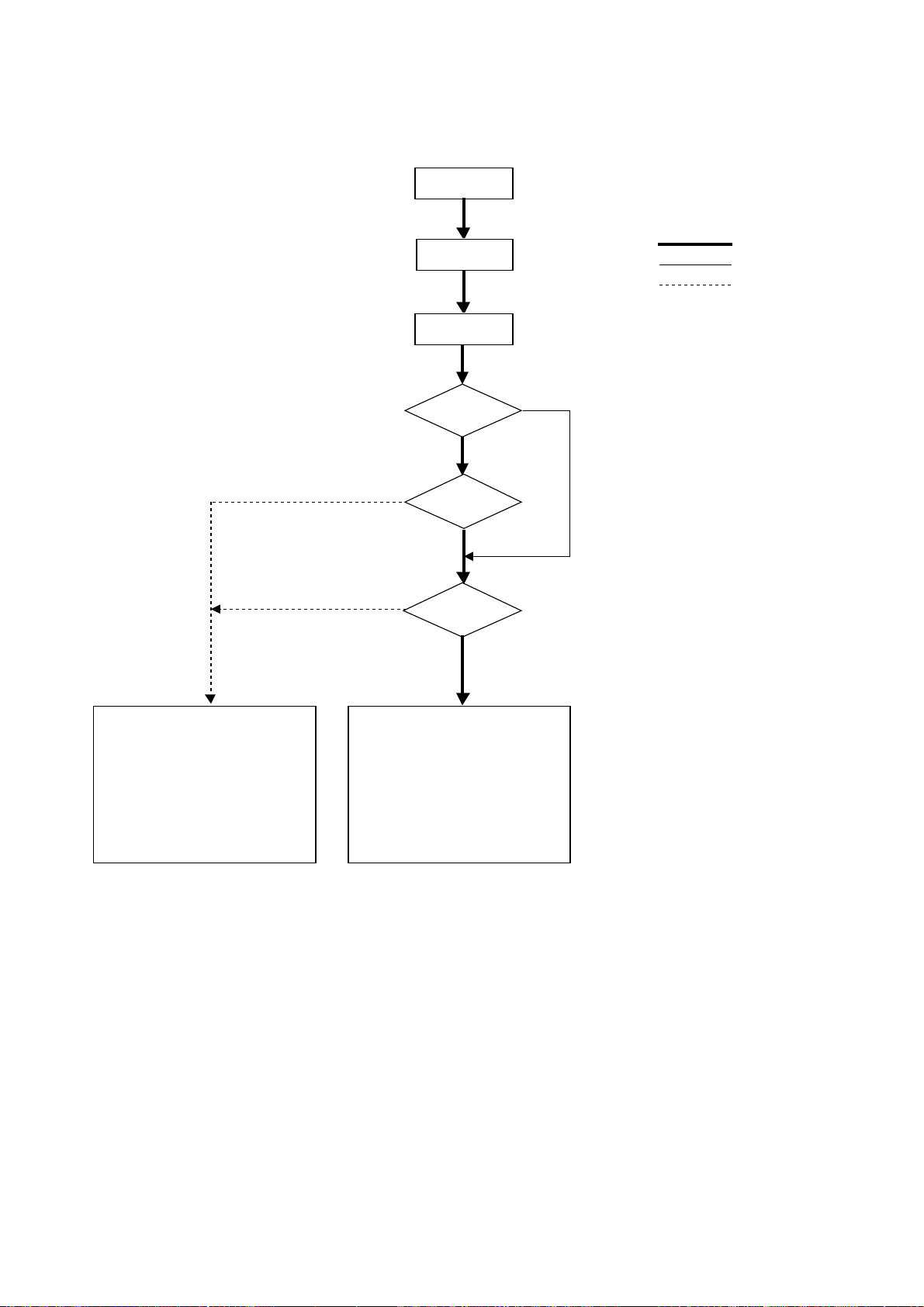
(4) Cooling operation
Cooling operation
NO
YES
4-way valve OFF
Indoor unit fan
operations
Test run start
NO
Thermostat ON
YES
3-minute
restart
prevention
NO
Normal operations
Test run
Stop
YES
1.Inverter output 0Hz
2.Indoor unit LEV, oil return LEV
3.Solenoid valve OFF
4.Outdoor unit fan stop
5.BC controller solenoid valve OFF
6.BC controller LEV fully closed
1.Inverter frequency control
2.Indoor unit LEV, oil return LEV
control
3.Solenoid valve control
4.Outdoor unit fan control
5.BC controller solenoid valve control
6.BC controller LEV control
–53–
Page 56

(5) Heating operation
Heating operation
4-way valve ON
NO
Thermostat ON
YES
Note : 1
Note : 2
Defrosting
operation
NO
Test run start
NO
YES
3-minute
restart
prevention
Normal operations
Defrosting operations
Stop
Test run
YES
4-way valve OFF
YES
1.Indoor unit fan stop
2.Inverter defrost frequency control
3.Indoor unit LEV fully opened, oil
return LEV fully closed
4.Solenoid valve control
5.Outdoor unit fan stop
6.BC controller solenoid valve control
7.BC controller LEV control
NO
1.Indoor unit fan very low speed
operations
2.Inverter output 0Hz
3.Indoor unit LEV, oil return LEV
fully closed
4.Solenoid valve OFF
5.Outdoor unit fan stop
6.BC controller solenoid valve
OFF
7.BC controller LEV fully closed
Note : 1 When outdoor unit starts defrosting, it transmits defrost operations command to (BC controller and) indoor unit, and the
Note : 2 Defrosting start condition : After integrated 50 minutes of compressor operations, and –8˚C: or less outdoor unit coil
indoor unit starts defrosting operations.
Similarly when defrosting operation stops, indoor unit returns to heating operation after receiving defrost end command of
outdoor unit.
Defrosting end condition : After 12 minutes of defrosting operation or the outdoor unit coil temperature (TH5 and TH7)
1.Indoor and outdoor unit fan
control
2.Inverter frequency control
3.Indoor unit LEV, oil return LEV
control
4.Solenoid valve control
5.BC controller solenoid valve
control
6.BC controller LEV control
temperature. (TH7)
having risen to 7˚C or more.
–54–
Page 57

(6) Dry operation
Dry operations
4-way valve OFF
Normal operations
Thermostat ON
Stop
1.Indoor unit fan stop
2.Inverter output 0Hz
3.Indoor unit LEV, oil return LEV
closed
4.Solenoid valve OFF
5.Outdoor unit fan stop
6.BC controller solenoid valve OFF
7.BC controller LEV fully closed
Test run start
NO
NO
Inlet temp. 18˚C
YES
1.Outdoor unit (Compressor) intermittent operations
2.Indoor unit fan intermittent operations
YES
(Synchronized with compressor :
low speed, OFF operations)
YES
Note : 1
Note : 2
Thermostat ON
Note : 1 When indoor unit inlet temperature exceeds 18˚C, outdoor unit (compressor) and indoor unit fan start intermittent operations
Note : 2 Thermostat is always kept on in test run, and indoor and outdoor unit intermittent operation (ON) time is a little longer than
synchronously. Operations of outdoor unit, BC controller, indoor unit LEV and solenoid valve accompanying compressor are
the same as those in cooling operations.
normal operations.
–55–
Page 58

[4] List of Major Component Functions
Name
Electronic
expansion
valve
Thermistor
Indoor unit
Compressor
High
pressure
sensor
Low
pressure
sensor
Pressure
switch
Thermistor
Outdoor unit
Code
(Function)
LEV
TH21
(Inlet air
temperature)
TH22
(Piping
temperature)
TH23
(Gas piping
temperature)
MC1
MC2
63HS
63LS
63H1
62H2
TH11,12
(Outlet)
TH2 (Low
pressure
saturation
temperature)
ApplicationProduct code Specification
1 Adjustment of super heat of heat
exchanger outlet port of indoor unit
during cooling.
2 Adjustment of sub-cool of heat ex-
changer outlet port of indoor unit
during heating.
Indoor unit control (Thermostat).
1 Indoor unit control (Freeze preven-
tion, hot adjust, etc.).
2 LEV control during heating (sub-cool
detection).
LEV control during cooling (super-heat
detection).
Uses the operating pressure to adjust
the operating frequency and adjust the
amount of circulating refrigerant.
When there is a load that cannot be
adjusted by MC1, this function ensures
the stable flow of refrigerant.
1 Detects high-pressure pressure.
2 Performs frequency control and high-
pressure protection.
1) Detects low-pressure.
2) Calculates the refrigerant circulation configuration.
3) Protects the low pressure
1 Detects high-pressure.
2 Performs high-pressure protection.
1 Detects high-pressure pressure.
2 Performs high-pressure protection.
0°C: 698 kΩ 60°C: 48 kΩ
10°C: 413 kΩ 70°C: 34 kΩ
20°C: 250 kΩ 80°C: 24 kΩ
30°C: 160 kΩ 90°C: 17.5 kΩ
40°C: 104 kΩ 100°C: 13.0 kΩ
50°C: 70 kΩ 110°C: 9.8 kΩ
1 Detects low pressure saturation tem-
perature.
2 Performs frequency control and liq-
uid level of accumulator.
DC 12 V
Amount of opening of the
stepping motor drive valve
60 to 2000 pulse.
(Gear Type)
R0 = 15 kΩ
B0/80 = 3460
Rt =
15exp{3460( - )}
1
273+t1273
Perform a continuity
check using a tester.
Conductivity among
white, red and orange.
Conductivity among yellow, brown and blue.
Orange
Resistance value
check
0°C: 15 kΩ
10°C: 9.7 kΩ
20°C: 6.4 kΩ
25°C: 5.3 kΩ
30°C: 4.3 kΩ
40°C: 3.1 kΩ
Low-pressure shell scroll
type. Winding resitance
0.481 (20°C).
Low-pressure shell scroll type.
Winding resistance: each phase.
1.996 (20°C): P400 YMF-C
1.197 (20°C): P500 YMF-C
Pressure
0 to 30 kg/cm2G
63HS
(0 to 2.94 MPa)
63LS
Vout 0.5 to 3.5 V
Connector
GND (Black)
Vout (White)
Vc (DC 5 V) (Red)
Pressure
0 to 10 kg/cm2G
(0 to 0.98 MPa)
Vout 0.5 to 3.5 V
(0.3 V/kg/cm2, V/MPa)
Gnd (black)
Vout (white)
Vc (DC 5 V) (Red)
Conductivity check
Connector
Connector
Set to 30 kg/cm2G
(2.94 MPa) OFF.
Resistance check
R120 = 7.465 kΩ
B25/120 = 4057
Rt =
7.465exp{4057( - )}
R0 = 33 kΩ
B0/100 = 3965
Rt =
33exp{3965( - )}
1
273+t1393
Resistance check
1
273+t1273
– 20°C: 92 kΩ
– 10°C: 55 kΩ
0°C: 33 kΩ
10°C: 55 kΩ
20°C: 13 kΩ
30°C: 8.2 kΩ
Inspection method
White
Red
M
Yellow Brown Blue
–56–
Page 59

Name
Thermistor
Outdoor unit
Solenoid
valve
Code
(Function)
TH4
(Liquid level
detection)
TH5
(Pipe
temperature)
(Outdoor
temperature)
TH7
(Pipe inlet
heat exchanger
temperature)
TH9
TH10
THHS inverter
heat sink temperature
SV1
dischargesuction
bypass
SV22
capacity
control (full
load)
SV32
capacity
control
(unload)
SV4a
dischargesuction
bypas
s
Detects liquid level of refrigerant inside
accumulator using the differences
among TH2, TH3, TH4.
1 Frequency control.
2 Controls defrosting during heating.
1 Detects the outdoor air temperature.
2 Performs fan control, liquid level
heater control, opening settings of
LEV for oil return and other functions.
Controls defrosfing during heating
1) Detects the CS circuit fluid temperature.
2) Calculates the refrigerant circulation
configuration.
1) Detects the compressor shell
temperature.
2) Provides compressor shell overheating protection.
Inverter cooling fan control using THHS
temperature.
1 Capacity control of high/low
pressure bypass when starting and
stopping.
2
Discharge pressure rise suppression.
Switching of capacity control valve inside
No. 2 compressor (Switching between
full load operation and unload operation)
(only P500 YMF-C).
Capacity control and controlling the rise
of high-pressure (Back-up of frequency
control).
R0 = 15 kΩ
B1/80 = 3460
Rt =
15exp{3460( - )}
1
273+t1273
0°C: 15 kΩ
10°C: 9.7 kΩ
20°C: 6.4 kΩ
25°C: 5.3 kΩ
30°C: 4.3 kΩ
40°C: 3.1 kΩ
R0 = 15 kΩ
B1/80 = 3460
Rt =
15exp{3460( - )}
1
273+t1273
0°C: 15 kΩ
10°C: 9.7 kΩ
20°C: 6.4 kΩ
25°C: 5.3 kΩ
30°C: 4.3 kΩ
40°C: 3.1 kΩ
R120 = 7.465 kΩ
B25/120 = 4057
Rt =
7.465exp
{4057( - )}
1
273+t1273+120
20°C: 250 kΩ 70°C: 34 kΩ
30°C: 160 kΩ 80°C: 24 kΩ
40°C: 104 kΩ 90°C: 17.5kΩ
50°C: 70 kΩ 100°C: 13.0kΩ
60°C: 48 kΩ 110°C: 9.8kΩ
R50 = 17 kΩ
B25/120 = 4170
Rt =
17exp {4170 ( - )}
1
273+t1323
0°C:181 kΩ
10°C:105 kΩ
20°C: 64 kΩ
25°C: 50 kΩ
30°C: 40 kΩ
40°C: 26 kΩ
AC 220 to 240 V
Open: conducting
Close: not conducting
AC 220 to 240 V
Close: conducting
Open: not conducting
AC 220 to 240 V
Open: conducting
Close: not conducting
Inspection methodApplicationProduct code Specification
Resistance checkTH3
Resistance checkTH6
Resistance check
Conductivity test
using tester
–57–
Page 60

Name
Solenoid
vallve
Linear
expansion
valve
Heater
Outdoor unit
4-way
valve
Code
(Function)
SV3~8 heat
exchanger
capacity
control
SV6a
dischargesuction
bypass
SLEV (Oil return)
CH11
CH12
crankcase
heater
CH2
CH3
Accumulator
liquid level
detection
21S4a
21S4b
Controls heat exchanger capacity of
outdoor unit.
Evaporation of liquid refrigerant inside
MC2.
Adjusts the rate of refrigerant (oil) returning from the accumulator.
Refrigerant heating inside compressor.
Refrigerant heating of accumulator
liquid level detection circuit.
Switching of cooling/heating cycle.
AC 220 to 240 V
Close: conducting
Open: not conducting
AC 220 to 240 V
Open: conducting
Close: not conducting
DC 12 V stepping motor drive
valve opening amount 0 to
480 pulse (Direct drive type).
Belt heater AC 200 to 240 V
MC1 1280 Ω 45 W
MC2 400:1280 Ω 45 W
500:1029 Ω 56 W
Code heater 2880 Ω
(1440 Ω + 1440 Ω)
AC 220 to 240 V
20 W (10 W + 10 W)
AC 220 to 240 V
Not conducting: cooling cycle
Conducting : heating cycle
Inspection methodApplicationProduct code Specification
Conductivity test
using tester.
Same as indoor unit
LEV. However, the
resistance value is
different than the indoor unit.
Resistance check
Resistance check
Conductivity check
using tester.
–58–
Page 61

[5] Resistance of Temperature Sensor
Thermistor for low temperature
Thermistor Ro= 15kΩ ± 3% (TH3 ~ 9) Thermistor R120 = 7.465kΩ ± 2% (TH1, 10)
t = 15exp {3460 ( - )} Rt = 7.465exp {4057 ( - )}
R
1
273+t
1
273+0
1
273+t
273+120
1
50
40
30
20
Resistance (kΩ)
10
0
–20 –10 10 20 30 40 500
25
20
15
10
Resistance (kΩ)
5
0
90 100 110 120
Temperature (˚C) Temperature (˚C)
Thermistor R
Rt = 33exp {3965 ( - )} Rt = 17exp {4170 ( - )}
o = 33kΩ ± 1% (TH2) Thermistor R50 = 17kΩ ± 2% (THHS)
1
273+t
1
273+0
1
273+t
1
273+50
Resistance (kΩ)
Resistance (kΩ)
Temperature (˚C) Temperature (˚C)
–59–
Page 62

66
6 REFRIGERANT AMOUNT ADJUSTMENT
66
By clarifying the relationship between the refrigerant amount and operating characteristics for BgR2 Series, conduct service
activities such as decision on the amount and adjustment of refrigerant on the market.
[1] Operating Characteristics and Refrigerant Amount
The followings are operating characteristics and refrigerant amount which draw special attention.
1
During cooling operations, required refrigerant amount tends to increase (refrigerant in accumulator decreases)
in proportion to increase in the number of operating indoor units. However, the change of increase rate is small.
2
During heating operations, liquid level of accumulator is the highest when all the indoor units are operating.
3
Discharge temperature hardly changes when increasing or decreasing refrigerant amount with accumulator
filled with refrigerant.
4
Tendency of
discharge
temperature
5
Compressor shell temperature is 20 ~ 70 degrees higher than low pressure saturation temperature (TH2) when
refrigerant amount is appropriate.
→ Judged as over replenishment when temperature difference from low pressure saturation temperature (TH2)
is 10 degrees or less.
During cooling operations, discharge temperature tends to rise at
overload than low temperature.
During heating operations, discharge temperature tends to rise at
low temperature than overload.
The lower the operating frequency is, the higher the discharge temperature
tends to become because of deteriorated compressor efficiency.
Comparison including
control system
[2] Adjustment and Judgement of Refrigerant Amount
(1) Symptom
The symptoms shown in the table below are the signs of excess or lack of refrigerant amount. Be sure to adjust the
amount of refrigerant in refrigerant amount adjustment mode, by checking operation status, judging refrigerant amount,
and performing LED monitor display with LED Dip S/W1, 1-10, for overall judgement of excess or lack of refrigerant
amount.
1
Error stop at 1500 remote controller display
(excessive refrigerant replenishment)
2
Operating frequency does not fully increase, thus resulting in
insufficient capacity
3
Error stop at 1102 remote controller display
(discharge temperature trouble)
4
Error stop at 1501 remote controller display
(low refrigerant trouble)
Excessive refrigerant replenishment
Insufficient refrigerant replenishment
–60–
Page 63

(2) Refrigerant Volume
1) Checking the Operating Condition
Operate all the indoor units in cooling or in heating, checking the discharge temperature, sub-cooling, low pressure
saturation temperature, inlet temperature, shell bottom temperature, fluid level, fluid step, etc. and rendering an overall
judgment.
Note:
Depending on the operating state, AL = 0 does not mean that there is insufficient refrigerant.
1 Discharge temperature is high. (125°C or higher)
Condition
2 Low pressure saturation temperature is extremely low.
3 Inlet superheating is high (if normal, SH = 20 deg. or lower).
4 Shell bottom temperature is high (the difference with the low pressure saturation
temperature is 70 deg. or greater)
5 Shell temperature is low (the difference with the low pressure saturation temperature is
10 deg. or lower).
6 Liquid level AL = 2
Refrigerant volume tends toward
insufficient.
Refrigerant volume tends toward
overcharge.
Judgment
2) Cautions When Judging the Liquid Level
If you are judging the liquid level, be sure the liquid level sensor function (sensor and heater) are operating normally.
1 Liquid Heater Disconnection Check
2 Liquid Heater Output Check
Turn 1 ON on the LED monitor display switch (SW1)
the signal for the heater relay to LED 5, then check the voltage of the heater terminal (AC
198 ~ 264 V) (leave the heater connections as they are).
3 Use the LED monitor display to check if there is misalignment between the actual
temperature and the detected temperature of TH2 ~ TH4.
Check Items Judgment
12345678910
ON
, and output
Normal if the resistance is 2.8 kΩ ± 7 %.
Normal if AC 198 ~ 264 V is output
together with the LED lighting.
3) Check the refrigerant volume by LED monitor display using the LED.
Set the LED monitor display switch (SW1) as shown below and check the past information (history) concerning the
refrigerant volume.
12345678910
Set SW1 as shown in he figure at right.
ON
If LD3 lights up, it indicates the refrigerant charge abnormal delay state just before emergency stop due to refrigerant overcharge (1500).
(3) Additional Refrigerant Charge Volume
At the time of shipping from the factory, the outdoor unit is charged with the amount of refrigerant shown in the
following table, but since no extension piping is included, please carry out additional charging on-site.
Outdoor Unit Model PURY-P400YMF-C PURY-P500YMF-C
Refrigerant Charge Volume 20 kg 22 kg
Calculation Formula
Calculate the additional refrigerant volume by calculating the size of the extension liquid piping and its length (units: m).
Additional Refrigerant Volume (kg) = (0.31 × L1) + (0.12 × L2) + (0.06 × L3) + (0.024 × L4) + α1 + α2
(Note 1)
In the calculation results, round up fractions smaller than 0.01 kg. (Example: 18.54 kg → 18.6 kg)
L
(α Calculation Table)
Total Capacity of Connected Indoor Units α1
161 ~ 330 2.0 kg
331 ~ 480 2.5 kg
481 ~ 630 3.0 kg
631 ~ 4.0 kg
1: Length of ø25.4 high press pipe (m)
L2: Length of ø12.7 liquid pipe (m)
L3: Length of ø9.52 liquid pipe (m)
L
4: Length of ø6.35 liquid pipe (m)
α1:refer to the calculation table.
α2
BC controller (master) only 0 kg
BC controller (slave) connected 3.0 kg
(Note 1) : In case high press pipe size (L1) is
ø22.22, 0.25 × L1.
–61–
Page 64

[3] Refrigerant Volume Adjustment Mode Operation
(1) Procedure
Depending on the operating conditions, it may be necessary either to charge with supplementary refrigerant, or to
drain out some, but if such a case arises, please follow the procedure given below.
1
Switching the function select switch (SW2-4), located on the outdoor unit’s control board, ON starts refrigerant
volume adjustment mode operation and the following operation occurs. (Refrigerant recovery mode and oil recovery
mode will be invalid.)
2
Additionally, if the LED monitor display switch (SW1) on the outdoor unit’s control board is set to
12345678910
ON
the accumulator’s liquid level is indicated by the LED lighting position.
AL = 0 (No fluid in accumulator)
AL = 1 (Liquid in accumulator)
AL = 2 (Overcharge)
Notes 1 Even if AL = 1 for a short time after operation in the refrigerant volume adjustment mode starts, as
time passes (as the refrigeration system stabilizes), it may change to AL = 0.
Notes 2 As the refrigerant volume can not be adjusted in the heating mode, retrieve the refrigerant, evacu-
ate air and then fill the specified volume of refrigerant if it is necessary to adjust the refrigerant
volume in the winter season.
Notes 3 A refrigerant volume adjustment performed in the cooling mode must be done with a gauge reading of 13 kg/cm2G or
higher.
If the pressure does not reach this guage reading the refrigerant cannot be collected.
Therefore, collect used refrigerant and evacuate the unit completely, and then fill new refrigerant up to a specified
quantity.
Notes 4 Judgment by the AL is at best only a rough guideline. Please do not add refrigerant based on the
AL reading alone. (Be sure to obtain calculations of the correct amount before adding refrigerant.)
Notes 5 When supplementing the refrigerant volume, please be careful to charge with liquid refrigerant.
TH1 SC11
,
12345678910
ON
SC16 Pd (High pressure)
12345678910
ON
12345678910
ON
12345678910
ON
–62–
Page 65

(2) Refrigerant adjustment in Cooling season (Flow chart)
In case of PURY-P400, 500YMF-C
Adjustment starts.
Start cooling operation of all indoor
units in a test run mode. Note 1
Has the
compressor been
operated for more than
30min?
Was the operation
condition stabilized?
The high pressure
> 13kg/cm2G?
*Operate for 5 minutes after adjusting the refrigerant and make a judgement.
TH1 ≤ 115˚C?
Fill refrigerant little by little from the
low-pressure side service port.
YES
NO
Note 1)As the refrigerant volume can not be adjusted in the heating mode,
retrieve the refrigerant, evacuate air and then fill the specified
volume of refrigerant if it is necessary to adjust the refrigerant
volume in the winter season.
Is the
thermostat turned
on/off in order for the indoor
unit to prevent from
frosting?
Stop the refrigerant volume adjustment
and retrieve the refrigerant. After
evacuating air, fill the specified volume
of refrigerant.
Are all indoor
units SHs more
than 6deg?
*Operate for 5 minutes after adjusting the refrigerant and make a judgement.
5deg ≤ SC11?
Note 2
10 ≤ SC16 ≤ 30deg?
Note 3
Is the LEV opening
degree stable when SH
< 6deg?
Fill refrigerant little by little from the
low-pressure side service port.
*Operate for 5 minutes after adjusting the refrigerant and make a judgement.
Retrieve the refrigerant little by little
30deg < SC16?
from the low-pressure side service
port.
Fill refrigerant little by little from the
low-pressure side service port.
*Operate for 5 minutes after adjusting the refrigerant and make a judgement.
TH1 ≤ 110˚C?
Adjustment completed.
Fill refrigerant little by little from the
low-pressure side service port.
–63–
Note 2)SC11 : Liquid refrigerant sub-cool for BC controller inlet
Note 3)SC16 : Liquid refrigerant sub-cool for BC controller outlet
Page 66

(3) Refrigerant adjustment in heating season (Flow chart)
In case of PURY-P400, 500YMF-C
Start
Adjustment
YES
Run all the indoor units in the
heating condition in the test run
mode.
Note: 1
Note: 2
Has the operating
condition stabilized?
Is the
Note: 3
accumulator's liquid level
AL = 0?
Charge with small amounts of
refrigerant at a time through the
low pressure service port.
After adjusting the refrigerant volume, run for 5
minutes and judge the AL.
Did the liquid level
change from AL = 0 to
AL = 1?
AL = 1 or 2
Is the
Note: 3
accumulator's liquid level
AL = 1?
Note: 4
Is the accumulator's
liquid level AL=0 when just one indoor
unit is running.
Drain out small amounts of
refrigerant at a time from the low
pressure service port.
Did the liquid level
change from AL = 1 to
AL = 0?
AL = 2
Adjustment is
not necessary.
Drain out small amounts of
refrigerant at a time from the low
pressure service port.
After adjusting the refrigerant volume, run for 5
minutes and judge the AL.
Did the liquid level
change from AL = 2 to
AL = 1?
NO
Finish charging with refrigerant. Finish draining out refrigerant. Finish draining out refrigerant.
Determine the difference between
the volume of refrigerant needed for
heating and the volume needed for
cooling and charge with that amount.
Draining out approximately 5 kg
of refrigerant.
Note: 5
Note: 6
Turn on switches No. 1, 2, 4, 5 and 6
of the self-diagnosis switch (SW1),
switching to the mode in which the
Adjustment
complated.
liquid level is displayed by the LED.
*
After adjusting the refrigerant volume, run for 5
minutes and judge the AL.
Is the
accumulator's liquid level
AL = 1?
Turn all of switches of
SW1 OFF.
Note: 7
Readjust.
If adjustment of the refrigerant volume was done by heating operation, it
is possible that accumulation of refrigerant due to the lengthened piping
could have a great influence, so it is recommended that operation be
checked during the cooling season.
Note: Do not let the drained out refrigerant escape to the outside atmo-
sphere.
Adjustment
complated.
–64–
Page 67

Note: 1 If there are any units which are not operating, it will cause refrigerant to accumulate, so by all means operate all the
indoor units. Also, in order to prevent stable operation from being disrupted by the thermostat going OFF, set the
trial operation mode.
Note: 2 If the high pressure is stabilized, it is safe to judge that the operation condition is stable.
Judge that operation is stabilized or not stabilized by whether the compressor starts after 3 or more minutes have
passed.
Note: 3 When turning on SW1 to
ON
, the LED will display the liquid level.
12345678910
Note: 4 If AL = 1, it indicates that adjustment is not necessary , but when the liquid level is on the low side even if it is in the
AL = 1 region, if one unit only is run and refrigerant is accumulating in the units that are stopped, it may result in
there being insufficient refrigerant, so at such a time, adjustment is necessary.
Note: 5 Determine the difference in the volume of refrigerant necessary for cooling and for heating as follows, and carry out
supplementary charging in accordance with the table below.
* The piping length is the total pipe length calculated for a high press pipe with a ø25.4 size.
Pipe Length
Additional Refrigerant
Volume
60 m or less 60 ~ 90 m
18 kg 27 kg 31 kg
90 m or longer
If the liquid pipe size is ø 12.7, the actual length is 0.3
If the liquid pipe size is ø 9.52, the actual length is 0.2
If the liquid pipe size is ø 6.35, the actual length is 0.1
–65–
Page 68

77
7 TROUBLESHOOTING
77
[1] Principal Parts
Pressure Sensor
(1) Judging Failure
1) Check for failure by comparing the sensing pressure according to the high pressure/low pressure pressure sensor
and the pressure gauge pressure.
Turn on switches 1, 3, 5, 6 (High) and 2, 4, 5, 6 (Low) of the digital display select switch (SW1) as shown below, and
the sensor pressure of the high pressure/low pressure sensors is displayed digitally by the light emitting diode LD1.
12345678910
High Pressure
Low Pressure
1 In the stopped condition, compare the pressure readings from the gauge and from the LD1 display.
(a) If the gauge pressure is 0~1 kg/cm
(b) If the pressure according to the LD1 display is 0~1 kg/cm2G (0.098MPa), there is faulty contact at the connec-
tor, or it is disconnected. Proceed to 4.
(c) If the pressure according to the LD1 display is 32 kg/cm
(d) If other than (a), (b) or (c), compare the pressure readings during operation. Proceed to 2.
ON
12345678910
ON
2
G (0.098MPa), the internal pressure is dropping due to gas leakage.
2
G (3.14MPa) or higher, proceed to 3.
2 Compare the pressure readings from the gauge and from the LD1 display while in the running condition.
(a) If the difference between the two pressures is within 1 kg/cm
2
G (0.098MPa), both the affected pressure sensor
and the main MAIN board are normal.
(b) If the difference between the two pressures exceeds 1 kg/cm
2
G (0.098MPa), the affected pressure sensor is
faulty (deteriorating performance).
(c) If the pressure reading in the LD1 display does not change, the affected pressure sensor is faulty.
3 Disconnect the pressure sensor from the MAIN board and check the pressure according to the LD1 display.
(a) If the pressure is 0~1 kg/cm
2
G (0.098MPa) on the LD1 display, the affected pressure sensor is faulty.
(b) If the pressure is 32 kg/cm2G (3.14MPa) (in the case of the low pressure sensor, 10 kg/cm2G (0.98MPa)) or
higher, the MAIN board is faulty.
4 Disconnect the pressure sensor from the MAIN board and short out the No. 2 and No. 3 pins of the connector
(63HS, 63LS), then check the pressure by the LD1 display.
(a) If the pressure according to the LD1 display is 32 kg/cm
2
G (3.14MPa) (in the case of the low pressure sensor,
10 kg/cm2G (0.98MPa)) or higher, the affected pressure sensor is faulty.
(b) If other than (a), the MAIN board is faulty.
2) Pressure sensor configuration.
The pressure sensors are configured in the circuit shown in the figure at right. If DC 5 V is applied between the red
and black wires, a voltage corresponding to the voltage between the white and black wires is output and this voltage
is picked up by the microcomputer. Output voltages are as shown below.
High Pressure 0.1 V per 1 kg/cm
2
G (0.098MPa)
Low Pressure 0.3 V per 1 kg/cm2G (0.098MPa)
–66–
Connector
63HS/
63LS
Vout 0.5~3.5 V
GND (Black)
Vout (White)
Vcc (DC5V) (Red)
Page 69

Solenoid Valve (SV1~8)
Check if the control board’s output signals and the operation of the solenoid valves match.
Setting the self-diagnosis switch (SW1) as shown in the figure below causes the ON signal of each relay to be output to
the LED’s.
Each LED shows whether the relays for the following parts are ON or OFF. When a LED lights up, it indicates that the
relay is ON.
SW1
12345678
LED
12345678910
ON
12345678910
ON
12345678910
ON
SV3 SV4 SV5 SV6 SV7, 8
2154a
2154b
SV6aSV4a
SV1
SV22/32
1) SV1 (Bypass valve)
1 Since SV1 will be set to ON 4 minutes after the compressor has started operation, confirm operation by monitoring the
LED display and listening for the operation of the solenoid valve.
2 It is possible to confirm the switching being performed by the operation of the solenoid valve while the unit is operating
by monitoring the temperature of the bypass circuit or the sound of the refrigerant.
2) SV22, SV32 (Full load/unload switching valve) (only P500YMF-C)
1 The No. 1 compressor is started first and operates for approximately 10 minutes and then the No. 2 compressor starts
in the unload mode. Since it will then switch to full load within 5 minutes, the operation can be confirmed by the LED
display and the operating temperature of the solenoid valve. (If the indoor unit operating is small, the No. 2 compressor
will not start.)
2 It is possible to determine whether or not the compressors are switching from unload to full load by check the changes
in amperage of the compressor at the moment of switching. The amperage under full load will be approximately 30 to
40 % more than operation under unload.
Note: The solenoid valve for SV22 is closed when conducting electricity while the SV32 is open when conducting
electricity.
3) SV4a (Bypass valve)
1 During unload operation in the cooling mode and when there is a rise in temperature and during unload operation in the
heating mode, SV4a will be set to ON according to conditions, making is possible to check operation by the LED
display and the operating sound of the solenoid valve.
2 It is possible to confirm the switching for the operating status by the temperature of the bypass circuit or the sound of
the refrigerant during the operation of the solenoid valve.
4) SV6b
When No. 2 compressor is operating and No. 2 compressor is stopped, the main SV6 will be set to ON, making it
possible to confirm operation by monitoring the LED display and listening to the operating sound. Note that it may be
set to OFF if the outlet temperature (TH11) exceeds 120°C .
5) 21S4a, 21S4b
21S4a, 21S4b are turned on during heating mode and heating-main mode.
6) SV3 ~ 8 (Control of heat exchanger capacity)
(a) Operations can be confirmed by LED display and operating sound of solenoid valve, because one or more of
SV3 ~8 are turned on depending on conditions during cooling-only operations.
(b) Operation can be confirmed by LED display and operating sound of solenoid valve, because all of SV3 ~ 8 are
turned on during heating-only operations.
(c) Operations can be confirmed by LED display and operating sound of solenoid valve, because one or more of
SV3 ~8 are turned on depending on conditions during cooling-principal and heating-principal operations.
–67–
Page 70

Solenoid Valves Block1
The refrigerant flow is as following figure. Hot gas (high pressured) flows in cooling mode and cool gas/liquid (low
pressured) flows in heating mode. Please refer to the Refrigerant Circuit Diagram.
And, ON/OFF of Solenoid valve is depends on the amount of running indoor units, ambient temperature and so on. So
please check by LED Monitor Display.
If the SV coil is taken off, then it is possible to open caps and check plungers. But the special tool which is on the Service
Parts List is needed.
* Closed torque : 13kg·m (1.3N·m)
–68–
Page 71

Solenoid Valves Block2
2
4
1
3
Solenoid V alves
Block 2
1
SV7
SV8
32 4
CV4b
CV7b
CV6b
CV5b
CV2b
CV3b
–69–
ST1
BV1
BV2
Page 72

Check Valves Block1
The refrigerant flow in the pipe 6, 7, 8 and 9 are depend on ON/OFF of the SV3, 4, 5 and 6.
Please confirm by LED monitor display.
You can open the cap of valve A, B and C, but 3 types of hexagon socket screw keys. The size is as follows.
* Closed torque : A : 1.7kg·m (0.17N·m)
B : 20kg·m (2.0N·m)
C : 13kg·m (1.3N·m)
–70–
Page 73

Check Valves Block2
1
3
5
6
4
7
2
CV5b
CV4b
CV6b
CV2b
Check V alves Block2
13576
CV3b
4
2
–71–
ST1
BV1
BV2
Page 74

Outdoor LEV
The valve percentage opening changes in proportion to the number of pulses.
(Connections between the outdoor unit’s MAIN board and SLEV, (PURY -P400·500YMF-C))
Pulse Signal Output and Valve Operation
Output (phase)
Output states
1234567 8
ø1 ON OFF OFF OFF OFF OFF ON ON
ø2 ON ON ON OFF OFF OFF OFF OFF
ø3 OFF OFF ON ON ON OFF OFF OFF
ø4 OFF OFF OFF OFF ON ON ON OFF
LEV Valve Closing and Valve Opening Operations
Valve Closing
Valve Opening
Valve Opening Angle (Flow Rate)
Fully Open
480 pulses
Output pulses change in the following orders when the
Valve is Closed 1→2→3→4→5→6→7→8→1
Valve is Open 8→7→6→5→4→3→2→1→8
*1. When the LEV percentage opening does not change,
all the output phases are off.
2. When the output is out of phase or remains ON
continuously, the motor cannot run smoothly, but move
jerkily and vibrates.
* When the power is switched ON, a 520 pulse valve
opening signal is output to make sure the valve’s
position, so that it is definitely at point A. (The pulse
signal is output for approximately 17 seconds.)
* When the valve operates smoothly, there is no sound
from the LEV and no vibration occurs, but when the
valve is locked, it emits a noise.
* Whether a sound is being emitted or not can be
determined by holding a screwdriver, etc. against it,
then placing your ear against the handle.
* If there is liquid refrigerant inside the LEV, the sound
may become lower.
Pulse Count
–72–
Page 75

Judgment methods and likely failure mode
Caution:
The specifications of the outdoor unit (outdoor LEV) and indoor unit (indoor LEV) differ. For this reason, there are
cases where the treatment contents differ, so follow the treatment specified for the appropriate LEV as indicated in
the right column.
Failure Mode Judgment Method Treatment Affected LEV
Microcomputer
driver circuit
failure
1 Disconnect the control board connector and connect
the check LED as shown in the figure below.
Indoor, BC controller
Outdoor
When the base power supply is turned on, the indoor LEV
outputs pulse signals for 10 seconds, the outdoor LEV
outputs pulse signals for 17 seconds, and BC controller
outputs pulse signals for 10-20 seconds.
If the LED does not light up, or lights up and remains on,
the driver circuit is abnormal.
In the case of driver circuit
failure, replace the control
board.
Indoor
BC controller
Outdoor
LEV mechanism
is locked.
The LEV motor
coils have a
disconnected
wire or is shorted.
Fully closed
failure (valve
leaks)
1 If the LEV is locked up, the drive motor turns with no
load and a small clicking sound is generated.
Generation of this sound when the LEV is fully closed
or fully open is abnormal.
Measure the resistance between the coils (red - white, red
- orange, brown - yellow, brown - blue) using a tester. They
are normal if the resistance is within 150Ω ± 10%.
Measure the resistance between the coils (gray - orange,
gray - red, gray - yellow, gray - black) using a tester. They
are normal if the resistance is within 46Ω ± 3%.
1 If you are checking the indoor unit’s LEV, operate the
indoor unit’s blower and the other indoor units in the
cooling mode, then check the piping temperatures
(liquid pipe temperatures) of the indoor units by the
operation monitor through the heat source unit’s
control board. When the fan is running, the linear
expansion valve is fully closed, so if there is leakage,
Thermistor
liquid pipe
(temperature sensor)
Linear
Expansion
Valve
the temperature sensed by the
thermistor (liquid pipe temperature
sensor) will become low. If the
temperature is considerably low
compared to the remote control’s
intake temperature display, it can
be judged that there is a fully
closed failure. In the case of
minimal leakage, it is not necessary to replace the
LEV if there are no other effects.
Replace the LEV.
Replace the LEV coils.
Replace the LEV coils.
If there is a large amount of
leakage, replace the LEV.
Indoor
BC controller
Outdoor
Indoor
BC controller
Outdoor
Indoor
BC controller
Faulty wire
connections in
the connector or
faulty contact.
1 Check for pins not fully inserted on the connector and
check the colors of the lead wires visually.
2 Disconnect the control board’s connector and conduct
a continuity check using a tester.
–73–
Check the continuity at the
places where trouble is found.
Indoor
BC controller
Outdoor
Page 76

Outdoor LEV (SLEV) Coil Removal Procedure (configuration)
As shown in the figure, the outdoor LEV is made in such a way that the coils and the body can be separated.
Coils
Stopper
Lead Wires
<Removing the Coils>
Fasten the body tightly at the bottom (Part A in the figure) so
that the body will not move, then pull out the coils toward the
top. If they catch on the stopper and are difficult to take out,
turn the coils left and right until the stoppers are free from the
stopper indentations, then pull the coils out.
If you take out the coils only without gripping the body, undue
force will be applied to the piping and the pipe may be bent
over, so be sure to fasten the body in such a way that it will not
move.
Body
Indentation for
Stopper
(12 places around
the circumference)
Part A
<Installing the Coils>
Fasten the body tightly at the bottom (Part A in the figure) so
that the body will not move, then insert the coils from the top,
inserting the coils’ stopper securely in one of the indentations
on the body. (There are four indentations for the stopper on
the body around its circumference, and it doesn’t matter which
indentation is used. However, be careful not to apply undue
force to the lead wires or twist them around inside the body .) If
the coils are inserted without gripping the body, it may exert
undue force on the piping, causing it to become bent, so be
sure to hold the body firmly so that it won’t move when installing the coils.
Part A
–74–
Page 77
Intelligent Power Module (IPM)
Measure resistances between each terminal of IPM with tester, and use the results for troubleshooting. Specified
resistance value is dependent on tester type to be used for resistance measurement, because diode inside IPM has
non-linearity, thus difference of impedance and voltage in tester being influential. As the internal impedance of
resistance range of analog tester equals to the center value of meter indication, the affect of internal impedance can
be minimized if the tester having close center value of resistance range. Because internal voltage is normally 1.5V,
the tester to be used for troubleshooting of IPM should satisfy the following conditions.
Internal voltage 1.5V (Power source : one dry cell battery)
Central value of resistance range 10 ~ 40Ω
The measured values for troubleshooting are shown in the table below.
(Use the minimum range for tester resistance range.)
• External view • Internal circuit diagram
1471016
B
P
N
• Judged value
Tester
+
Tester –
P
U
V
W
N
W
V
P
UVWN
∞∞∞∞
2~
100Ω
2~
100Ω
2~
100Ω
2~
100Ω2~100Ω2~100Ω2~100Ω
3
2
Pre-Driver
1
6
5
Pre-Driver
4
9
8
Pre-Driver
U
∞
7
11
13
Pre-Driver
10
14
Pre-Driver
15
Pre-Driver
12
∞
∞
Over heating
16
protection circuit
P
U
V
W
B
N
Diode stack
Perform continuity check with tester. Judged as normal if the following characteristics are observed.
(Use the minimum range for tester resistance range.)
Tester ⊕
Tester -
1 10~50Ω∞
2 10~50Ω∞
3 10~50Ω∞
Tester -
Tester
123
⊕
1 ∞ 10~50Ω
+
2 ∞ 10~50Ω
3 ∞ 10~50Ω
1
2
3
–
+–
+–
–75–
Page 78

(2) Trouble and remedy of remote controller
(In the case of MA remote controller)
Phenomena Factors Check method and handling
1
If pushing the remote
control operation SW
does not make a
sound such as feep
with the crystal
display lamp out, and
no operate is
possible.
(An appropriate
display on the
remote control is not
on.)
1) Power supply from transformers is not turned on in
Indoor Unit.
1 The original power supply of Indoor Unit is not
turned on.
2 The connector (CND. CNT, CN3T) on the
controller board in the room has come off.
3
Fuse on the control board in Indoor Unit has melting down.
4
Transformer defects or damage to unit.
2) MA remote controller has been wired incorrectly.
1 Break of the MA remote controller line and the
connection to the terminals has come off.
2 Short circuit of the MA remote control wiring
3 Reversed connections of the wiring on remote
controller.
4 Incorrect connection of the MA remote control wiring
to the transmission line terminal block (TB 5).
5 Reversed connections between the MA remote
control wiring in the indoor unit and AC 200V
power supply wiring.
6 Reversed connection between the MA remote
control wiring in the indoor unit and M-NET
transmission wiring.
3) The maximum number of MA remote controllers
connected to one is unit exceeded (two units).
4) The wiring length of the MA remote line and the
used electric wire diameter is out of specifications.
5) The wiring of the remote display output to the
outdoor unit is short circuited, or the relay is
connected with reversed polarity.
6) Defective of the controller board in the room
7) Defects of MA remote control
a) Check the MA remote control terminal
voltage (between A and B).
i) In the case of voltage DC8.5- 12V,
the remote controller is defective.
ii) In the case of voltage not available:
●
Check the left described 1) and 3),
after checking , if these are factors,
then modifications should be
performed.
●
If there are no factors of the left
described 1) and 3), move to b).
b) Remove the remote control wiring from
the terminal block TB13 for the MA
remote control in the indoor unit, and
check voltage between A and B.
i) In the case of voltage DC9-12V
Check the left described 2) and 4), if
these are factors, then modifications
should be performed.
ii) In the case of voltage not available:
●
Recheck the left described 1) once
again, if this is a factor, them
modifications should be performed.
●
If there are no factors in the left
described 1), check the wiring for the
remote display (the relay polarity, etc.)
●
If there are no factors, replace the
controller board in the indoor unit.
In the case of item 1), the
LED 1 on the controller
board in the unit is off.
2
When turning on the
remote control
operation SW, a
temporary operation
display is indicated,
and the display lights
out immediately, the
unit stops.
Check method and handling
The same
phenomena occurs in all units of
the same refrigerant system?
Self-diagnosis LED
check
7120 error display?
1) M-NET transmission power supply from the outdoor unit is not
supplied.
1 The original power supply of the outdoor unit is not turned on.
2 Disconnection of connectors on the board of the outdoor unit.
Main board --- CNS1, CNVCC3
INV board --- CNAC2, CNVCC1, CNL2
3 Power supply circuit defects of the outdoor unit.
(For detail, refer to Pages 127)
●
INV board defects
●
Blown fuse (F1 on INV Board)
●
Diode stack destruction
●
Prevention resistance of rush current (R1) damage
2) Transmission line short
3) Wiring mistakes of the M-NET transmission line on the side of
the outdoor unit
1 Break of transmission line, and removal of terminal block
2 The room transmission line is wired to the transmission line
terminal block (TB7) for the central control by mistakes.
4) M-NET transmission line break on the side of the room unit
5)
Disconnection off wiring between the M-NET transmission terminal block
(TB 5) and the room controller board CN2M and pulls off of connectors
NO
YES
Check for 4) item
YES
Check for 2) and 3) of
factors
In the case of factors 2) and
3) Indicated by 7102 error
code on the self-diagnosis
LED of the outdoor unit.
Terminal block (TB15)
voltage check for the
transmission line of the
indoor unit
NO
19 ~ 12V?
YES
Check for 5) item
NO
Check for 1) item
Modify the defect
–76–
Modify the defect
YES
Factors available?
Defects in the indoor
unit controller board or
MA remote control
NO
Page 79

Phenomena Factors
3 When the remote
control SW is turned
on, the indication
goes off after
approximately 20- 30
seconds, and indoor
unit stops.
Check method and handling
Check the BC controller
power terminal block
voltage
1) Power supply from the transformer is not available to the control board of BC controller.
1 The original power supply of the BC controller is not turned on.
2 Removal of connectors (CN12, CN38, CNTR) on the control board of the BC controller.
3 Fuse on the control board of the BC controller is blown.
4 Transformer defects of the BC controller and a malfunction.
5 Defects on the control board of the BC controller
220 ~ 240V?
YES
Fuse check on the
board
Fuse blown off
NO
Connector removal
checks
(CN03, CN12, CNTR)
Removed?
NO
Check for resistance
value of transformer
Within spec.?
YES
BC controller
Defects for the
control board
NO
YES
YES
NO
Verify the power
supply wiring original
power supply.
220 ~ 240V circuit
short and ground
checks
Connector connection
defects
Check for factors of
transformer cut
Earth route on the board
Earth route of sensor
and LEV
*1
Modify the defective
places
Power supply
reapplying
*1 As for transformer checks, It is subject to the failure judgment method of main parts in 4.5.
–77–
Page 80

Phenomena Factors
4 “HO” indication on
the remote controller
is not lit, and the
ON/OFF switch does
not work.
1) The M-NET transmission power supply form the
outdoor unit is not supplied.
1 The original power supply of Indoor Unit is not
turned on.
2 The connector on the controller board in Indoor
Unit is removed.
Main board ----CNS1, CNVCC3
INV board----CNAC2, CNVCC1, CNL2
3
Power supply circuit defects of the outdoor unit.
(For detail, refer to Pages 127)
●
INV board defects
●
Diode stack defects
●
Prevention resistance of rush current (R1)
damage.
2) Short circuit of the M-NET transmission line
3) Error wiring of the M-NET transmission line on the
side of the outdoor unit
1 A break of the transmission line or terminal block
removal
2 Indoor Unit transmission line is wired to the
transmission line terminal block (TB7) for the
central control by mistake.
4) M-NET transmission line break on the side of Indoor
Unit (Short/ Open)
5)
Loose or disconnection of wiring between the M-NET
transmission terminal block (TB 5) of Indoor Unit and
Indoor Unit controller board CN2M and disconnection of
connectors
6) Error wiring of the MA remote control
1 Short circuit of the MA remote wiring
2 A break of the MA remote control line (No.2) and
disconnection
3
Reversed wiring, cross-over in the group control
of the terminal block connection
4 Wire by mistakes the MA remote control to the
terminal block (TB5) for the transmission line
5
Connect by mistakes the M-NET transmission line to
the MA remote control terminal block (TB13)
7) The unit address is not “00” as it should be with
automatic address setting.
8) The address of
Indoor Unit
becomes 51 or more.
9) The master and slave setting of the MA remote
control becomes the slave setting.
10)Use the M-NET remote control in spite of the
automatic address.
11)Defects for the room controller board (MA remote
communication circuits)
12)Defects for the remote controller
In the case of 2), 3) and 7)
factors, indicate 7102 errors
by the self-diagnosis LED of
the outdoor unit.
Check method and handling
phenomena in all unit of the same
The same
refrigerant system happen?
YES
Self-diagnosis LED
checks
7120 error display?
NO
Check for 11) item
Factors
available?
NO
Check for 1) item
YES
NO
YES
Check for 2) and 3) of
factors
Change the M-NET
remote control to the
MA remote control.
Modify the defective
places
Check for 4) item
Modify the defective
places
Modify the defective
places
Check for the terminal
block (TB15) voltage
for the transmission
line of the indoor unit
NO
YES
19 ~ 12V?
Check the items of
5), 6), 8), 9), and 10)
Factors available?
Defects of the indoor
unit controller board or
MA remote control
YES
NO
–78–
Page 81

(In the case of M-NET remote controller)
Symptom Cause Checking method & countermeasure
1
Despite pressing of
remote controller
ON/OFF switch,
operation does not
start and there is no
electronic sound.
(No powering signal
appears.)
2
At about 10 seconds
after turning remote
controller operation
switch ON, the
display distinguishes
and the operation
stops.
1) M-NET transmission power source is not supplied
from outdoor unit.
1 Main power source of outdoor unit is not
connected.
2 Disconnection of connector on outdoor unit circuit
board.
Main board : CNS1, CNVCC3
INV board : CNAC2, CNVCC1, CNL2
3 Faulty power source circuit of outdoor unit.
• Faulty INV board,
• Blown fuse (F1 on INV board)
• Broken diode stack
• Broken resistor (R1) for rush current protection
2) Short circuit of transmission line.
3) Erroneous wiring of M-NET transmission line at outdoor unit.
1 Transmission line disconnection or slipping off from terminal
block.
2 Erroneous connection of indoor/outdoor transmission line to
TB7.
4) Disconnection of transmission wiring at remote controller.
5) Faulty remote controller.
1) Power source is not fed to indoor unit from transformer.
1 Main power source of indoor unit is not turned on.
2 Disconnection of connector (CND, CNT, CN3T) on indoor controller board.
3 Blown fuse on indoor controller board.
4 Faulty or disconnected transformer of indoor unit.
5 Faulty indoor controller board.
2) Faulty outdoor control circuit board uncontrolled.
As normal transmission is fails between indoor and outdoor units, outdoor unit model can not be
recognized.
a) Check transmission terminal block of
remote controller for voltage.
i) In case of 17 ~ 30V
→ Faulty network remote controller
ii) In case of less than 17V
→ See “Transmission Power Circuit
(30V) Check Procedure”.
The cause of 2) and 3) is
displayed with self-diagnosis
LED for 7102 error.
Checking method & countermeasure
Check indoor LED3
Lighting?
Lighting
Check for the change of LED
display by operating dip switch
SW1 for self-diagnosis.
Extinguishing or
unable to confirm
Check indoor unit
power source terminal
block voltage
AC 220~240V?
YES
Check fuse on circuit
board
Blown?
NO
Check connection of connector (CND, CNT , CN3T)
Disconnected
NO
Check transformer
resistance value
Within rated?
YES
Check self-diagnosis
function of outdoor unit
Changed?
NO
YES
YES
*1
NO
NO
Check main power source
of power source wiring.
Check 220V~240V
circuit for short circuit
and ground fault.
Improper connector
connection
Check cause of transformer disconnection.
•Ground fault on circuit
board
•Ground fault on
sensor, LEV
Apply power
source again.
Check self-diagnosis function after powering outdoor unit again.
NO
Faulty outdoor unit
control circuit board
Repair
faulty point.
YES
Faulty indoor
controller board
Changed?
YES
Accidental
trouble
*1 Check the transformer in accordance with the “TROUBLE SHOOTING” in the indoor unit’s service handbook.
–79–
Page 82

Symptom Cause
3 “HO” display on re-
mote controller does
not disappear and
ON/OFF switch is
(Without using MELANS)
1) Outdoor unit address is set to “00”
2) Erroneous address.
1 Address setting of indoor unit to be coupled with remote controller incorrect.
ineffective.
2 Address setting of remote controller incorrect.
3) Faulty wiring of transmission terminal block TB5 of indoor unit in the same group with remote
controller.
4) Centralized control SW2-1 of outdoor unit is turned ON.
5) Setting to interlocking system from indoor unit (Switch 3-1 = OFF), while Fresh Master is intended to
be use by remote controller operation (indoor unit attribute).
6) Disconnection or faulty wiring of indoor unit transmission line.
7) Disconnection between indoor unit M-NET transmission line terminal block (TB5) and connector
CN2M.
8) More than 2 sets of power supply connector (CN40) are inserted into centralized control transmission line of outdoor unit.
9) Faulty outdoor unit control circuit board.
10)Faulty indoor controller board.
11)Faulty remote controller.
(Interlocking control with MELANS)
12)No grouping registration from MELANS (Neglecting to set the relation between indoor unit and
network remote controller).
13)Disconnection of centralized control transmission line (TB7) at outdoor unit.
14)At system connected with MELANS, power supply connector (CN40) is inserted to centralized
control transmission line of outdoor unit.
Checking method & countermeasure
(Indoor unit = remote controller - 100.)
(Remote controller = indoor unit + 100.)
In case MELANS is not used
Same symptom for all
units in a single refrigerant system?
YES
Check outdoor unit
address
51 ~ 100?
YES
Check centralized
control switch SW2-1 at
outdoor unit
ON?
NO
Faulty outdoor unit
control circuit board
NO
NO
YES
Outdoor unit
address setting miss
Switch setting
miss
Change from
ON to OFF
Address setting
miss of remote
controller
Indoor address
setting miss
Transmission line
wiring miss of indoor unit M-NET
Disconnection
of CN2M
connector
Confirm address of remote
controller with “HO” displayed
NO
NO
NO
Check connection between indoor unit M-NET transmission terminal block (TB5) and connector CN2M
YES
Indoor unit + 100?
YES
Check address of
coupling indoor unit
Remote controller
-100?
YES
Check voltage of indoor unit MNET transmission terminal block
17 ~ 30V?
YES
Disconnection
NO
Check Fresh Master SW3-1
NO
Faulty indoor controller board
or remote controller
ON?
YES
Repair spot
in trouble
Setting miss of
Fresh Master
SW3-1
In case with MELANS used
When MELANS is used, “HO” display on the remote controller will disappear at the group registration of the indoor unit and local
remote controller.
If “HO” does not disappear after the registration, check the items 12) ~ 14) in the Cause column.
–80–
Page 83

Symptom Cause Checking method & countermeasure
4 “88” appears on re-
mote controller at
registration and
access remote
controller
[Generates at registration and confirmation]
1) Erroneous address of unit to be coupled.
2) Disconnection of transmission line of unit to be
coupled (No connection).
3) Faulty circuit board of unit to be coupled.
4) Installation miss of transmission line.
a) Confirm the address of unit to be
coupled.
b) Check the connection of transmission
line.
c) Check the transmission terminal block
voltage of unit to be coupled.
i) Normal if voltage is DC17 ~ 30V
ii) Check the item d) in case other than i).
[Confirmation of different refrigerant system controller]
5) Disconnection of power source of outdoor unit to be
confirmed.
6) Disconnection of centralized control transmission
line (TB7) of outdoor unit.
7) Power supply connector (CN40) is not inserted into
centralized control transmission line in grouping
with different refrigerant system without using
MELANS.
8) More than 2 sets of power supply connector are
inserted into the centralized control transmission line
of outdoor unit.
9) In the system connected with MELANS, power
supply connector (CN40) is inserted into the
centralized control transmission line of outdoor unit.
10)Short circuit of centralized control transmission line.
d) Confirm the power source of outdoor unit
to be coupled with the unit to be
confirmed.
e) Confirm that the centralized control
transmission line (TB7) of outdoor unit is
not disconnection.
f) Confirm the voltage of centralized control
transmission line.
i) Normal in case of 10V ~ 30V
ii) Check the items 7) ~ 10) left in case
other than i).
–81–
Page 84

Transmission Power Circuit (30 V) Check Procedure
If “” is not displayed by the remote control, investigate the points of the trouble by the following procedure and correct it.
No. Check Item Judgment Response
1
Disconnect the transmission line from TB3
and check the TB3 voltage.
DC24~30 V
Check the transmission line for the following, and
correct any defects.
Broken wire, short circuit, grounding, faulty
contact.
2
Check if the following connectors are
disconnected in the outdoor unit’s control
box.
MAIN Board: CNS1, CNVCC3, CNVCC4
INV Board: CNVCC2, CNVCC4, CNL2,
CNR, CNAC2
3
Disconnect the wires from CNVCC3 on the
Main board and check the voltage between
pins 1 and 3 on the wire side of the
CNVCC3.
Tester + .....1 pin
Tester - .....3 pin
4
Disconnect the wiring from CNVCC2 on the
INV board and check the voltage between
pins 1 and 3 of CNVCC2.
Tester + .....1 pin
Tester - .....3 pin
5
Disconnect the wiring from CNL2 on the
INV board, and check the resistance at
both ends of choke coil L2.
6
Disconnect the wiring from CNR on the INV
board, and check the resistance at both
ends of R7.
Except the above-mentioned
Connector disconnected
Except the above-mentioned
DC24~30 V
Except the above-mentioned
DC24~30 V
Except the above-mentioned
0.5~2.5Ω
Except the above-mentioned
19~25Ω
Except the above-mentioned
Go to No. 2
Connect the connectors as shown on the electric
wiring diagram plate.
Go to No. 3
Check the wiring between CNS1 and TB3 for the
following, and correct any defects.
Broken wire, short circuit, grounding, faulty
contact.
If there is no trouble, replace the Main board.
Go to No. 4
Check the wiring between CNVCC2 and
CNVCC3 for the following, and correct any
defects.
Broken wire, short circuit, grounding, faulty
contact.
Go to No. 5
Go to No. 6
Replace choke coil L2.
Go to No. 7
Replace R7.
7
Check the resistance at both ends of F01
on the INV board.
8
Check the voltage between pins 1 and 3 of
CNAC2 on the INV board.
9
Check the voltage between L2 and N on
power supply terminal block TB1.
0Ω
Except the above-mentioned
AC198~264 V
Except the above-mentioned
AC198~264 V
Except the above-mentioned
Go to No. 8
Replace F01
Replace the INV board.
Go to No. 9
Check the wiring to CNAC2 for the following and
correct any defects.
Broken wire, faulty contact.
Check the power supply wiring and base power
supply, and correct any defects.
–82–
Page 85

(3) Investigation of transmission wave shape/noise
Control is performed by exchanging signals between outdoor unit, indoor unit and remote controller by M-NET
transmission. If noise should enter into the transmission line, the normal transmission will be hindered causing
erroneous operation.
1) Symptom caused by the noise entered into transmission line
Cause Erroneous operation Error code
Noise entered into
transmission line
Signal changes and is misjudged as the signal of other
address.
Transmission wave shape changes to other signal due to
6600
6602
noise.
Transmission wave shape changes due to noise, and can
6607
not be received normally thus providing no reply (ACK).
Transmission can not be made continuously due to the
6603
entry of fine noise.
Transmission can be made normally, but reply (ACK) or
answer can not be issued normally due to noise.
6607
6608
2) Method to confirm wave shape
No fine noise allowed *1
<with transmission>
<without transmission>
VHL
52 µs
Logical
VBN
52 µs
value “0”
Logical
52 µs
value “1”
52 µs52 µs
No fine noise allowed *1
Check the wave shape of transmission line with an oscilloscope to confirm that the following conditions are being
satisfied.
1 The figure should be 104µs/bit ± 1%.
2 No finer wave shape (noise) than the transmission signal (52µs ± 1%) should be allowed. *1
3 The sectional voltage level of transmission signal should be as follows.
Logic value Transmission line voltage level
0VHL = 2.0V or more
1VBN = 1.3V or less
*1 However, minute noise from the DC-DC converter or inverter operation may be picked up.
–83–
Page 86

3) Checking and measures to be taken
(a) Measures against noise
Check the items below when noise can be confirmed on wave shape or the error code in the item 1) is generated.
Items to be checked Measures to be taken
1 Wiring of transmission and power lines in
crossing.
2 Wiring of transmission line with that of other
system in bundle.
3 Use of shield wire for transmission line (for
both indoor unit control and centralized
control).
4 The shield is to be daisy changed exactly the
same as the transmission line.
Checking for wiring method
5 Are the units and transmission lines grounded
as instructed in the INSTALLATION MANUAL?
6 Earthing of the shield of transmission line (for
indoor unit control) to outdoor unit.
7 Arrangement for the shield of transmission line
(for centralized control).
Check for earthing
Isolate transmission line from power line (5cm or more).
Never put them in the same conduit.
Wire transmission line isolating from other transmission line.
Wiring in bundle may cause erroneous operation like crosstalk.
Use specified transmission wire.
Type : Shield line CVVS/CPEVS
Wire diameter : 1.25mm2 or more
The transmission line is wired with 2-jumper system. Wire the shield
with jumper system as same for transmission line.
When the jumper wiring is not applied to the shield, the effect against
noise will be reduced.
Connect to ground as shown in the INSTALLATION MANUAL.
One point earthing should be made at outdoor unit.
Without earthing, transmission signal may be changed as the noise on
the transmission line has no way to escape.
For the shield earth of the transmission line for centralized control, the
effect of noise can be minimized if it is from one of the outdoor units in
case of the group operation with different refrigerant systems, and from
the upper rank controller in case the upper rank controller is used.
However, the environment against noise such as the distance of transmission line, the number of connecting sets, the type of connecting controller, and the place of installation, is different for the wiring for centralized control. Therefore, the state of the work should be checked as follows.
a) No earthing
• Group operation with different refrigerant systems
One point earthing at outdoor unit
• Upper rank controller is used
Earthing at the upper rank controller
b) Error is generated even though one point earth is being con-
nected.
Earth shield at all outdoor units.
Connect to ground as shown in the user’s manual.
(b) When the wave height value of transmission wave shape is low, 6607 error is generated, or remote controller is
under the state of “HO.”
Items to be checked Measures to be taken
8 The farthest distance of transmission line is
exceeding 200m.
9 The types of transmission lines are different.
0 No transmission power (30V) is being supplied
to the idoor unit or the remote control.
A Faulty indoor unit/remote controller.
Confirm that the farthest distance from outdoor unit to indoor unit/
remote controller is less than 200m.
Use the transmission wire specified.
Type of transmission line : Shield wire CVVS/CPEVS
Wire dia. of transmission line : 1.25mm2 or more
Refer to “Transmission Power Supply (30V) Circuit Check Procedure.”
Replace outdoor unit circuit board or remote controller.
–84–
Page 87

4) T reatment of Inverter and Compressor T roubles
If the compressor does not work when error codes 4240, 4250, 4340 or 4350 are detected, determine the point of
malfunction by following the steps in the LED monitor display and countermeasures depending on the check
code displayed, then perform the procedures below.
No. Check Item Symptoms T reatment
How many hours was the
power kept on before
1
operation?
1 If it was kept on for 12 hours or
longer as specified.
2 It was kept on for less than the
specified period.
Go to [2].
Go to [2] after keeping the power on for the
specified time.
When it is restarted, does
2
the trouble reappear?
3
Run the outdoor unit with
the wiring to the compressor
disconnected. At this time,
change SW1-1 on the INV
board to ON.
Note) The terminals of the 3
disconnected wires should
be isolated from each other.
*1 [Cautions when measuring the voltage and current of the inverter’s power circuit.]
1 The compressor stops and the
same error code is displayed.
1 The Inverter stops and the same
error code is displayed.
2 If the inverter’s output voltage is
output with good balance, *1.
3 If the balance in the inverter’s
output voltage is not good or if the
inverter’s output voltages are all 0 V
(a digital tester cannot be used) *1.
Perform the check of wiring shown in the
explanation of each error code.
Check the IPM is faulty. (Go to “Individual
Parts Failure Judgment Methods.”)
Check the coil resistance and insulation
resistance of the compressor, and if it is
normal, run it again, and if the trouble occurs
again, replace the compressor.
* Insulation resistance : 2MΩ or more
Coil resistance : 0.359 ~ 0.716Ω
Check the IPM.
Judge that the IPM is faulty. (Go to “Indi-
vidual Parts Failure Judgment Methods.”)
If the IPM is normal, replace the G/A board,
then perform this item again with SW1-1 ON.
If the problem is not solved, replace the INV board.
If the problem is solved and you connect the
compressor again, turn SW1-1 OFF again.
Check the compressor’s coil resistance and
insulation resistance.
Since the voltage and current on the inverter’s power supply side and its output side do not have a sine waveform, the
measurement values will differ depending on the measuring instrument and the circuit measured.
In particular, as the inverter’s output voltage has a pulse waveform, the output frequency also changes, so differences in
measurement values will be great depending on the measuring instrument.
1 When checking if the inverter’s output voltage is unbalanced or not (relative comparison of the voltages between
each of the lines), if you are testing with a portable tester, be sure to use an analog tester.
Use a tester of a type which can be used to judge if the IPM or diode module is faulty.
In particular, in cases where the inverter’s output frequency is low, there are cases where the variations in measured
voltage values between the different wires will be great when a portable digital tester is used, when in actuality they
are virtually equal, and there is danger of judging that the inverter is faulty.
2 It is recommended when checking the inverter’s output voltage values (when measuring absolute values), that, if a
measuring device for business frequencies is used, a rectified voltage meter (with a
Correct measurement values cannot be obtained with an ordinary portable tester. (either analog or digital)
symbol) be used.
–85–
Page 88

5) T reatment of Fan Motor Related T roubles
Condition Possible Cause Check Method and T reatment
1 The fan motor will not run
for 20 minutes or longer
when the AK value is
10%. (When the MAIN
board’s SW1 is set as
shown below, the AK
value is displayed by the
service LED.)
SW1 = 1110001000
2 The fan motor’s vibration
is great.
1) The power supply voltage
is abnormal.
2) Wiring is faulty .
If there is an open phase condition before the breaker, after
the breaker or at the power supply terminal blocks TB1A or
TB1B. Correct the connections.
If the power supply voltage deviates from the specified
range. Connect the specified power supply.
For the following wiring, 1 check the connections, 2 check
the contact at the connectors, 3 check the tightening torque
at parts where screws are tightened, 4 check the wiring
polarity , 5 check for a broken wire and 6 check for grounding.
TB1A~NF~TB1B~CNTR1~T01~CNTR,
TB1B~CNPOW, CNF AN~CN04~CNMF,
CNFAN~52F~CN05~CNMF
CNFC1~CNFC2
* Check if the wiring polarity is as shown on the wiring
diagram plate.
3) The motor is faulty.
4) A fuse (F1, F2, F3) is
defective.
5) The transformer (T01) is
defective.
6) The circuit board is faulty.
Measure the resistance of the motor’s coils: 20~60Ω
Measure the motor’s insulation resistance with a megger:
10 MΩ (DC 500 V) or more
If a fuse is defective, replace it.
Judge that T01 is faulty . Go to “Individual Parts Failure
Judgment Methods.”
If none of the items in 1) to 5) is applicable, and the trouble
reappears even after the power is switched on again,
replace the circuit board using the following procedure.
(When replacing the circuit board, be sure to connect the
connectors and ground wire, etc. securely .)
1 Replace the FANCON board only. If the problem is
saved, the FANCON board was defective.
2 Replace the FANCON board and replace the MAIN
board. If the problem is saved, the MAIN board is
defective.
3 If the trouble continues even after 1 and 2 above, then
both boards are defective.
–86–
Page 89

6) T roubleshooting at breaker tripping
Check items Measures to be taken
1 Check the breaker capacity.
The breaker’s capacity should be correct to “System
design” in data book.
2 Check for a short circuit or grounding in the electrical
system other than the inverter.
3 Check the resistance between terminals on the terminal
block TB1A for power source.
1 0 ~ several ohms or improper megohm value
4 Checking by powering again.
1 Main power source circuit breaker tripping
2 No display of remote controller
5 Operational check by operating air conditioner
Correct any defects.
Check each part inside the inverter power circuit
(resistance, megohm or the like).
a) Diode stack
Refer to “Troubleshooting of diode stack.”
b) IPM
Refer to “Troubleshooting of IPM.”
c) Rush current protection resistor
d) Electromagnetic contactor
e) DC reactor
* For c) ~ e), refer to “Individual Parts Failure Judge-
ment Methods.”
1 Normal operation without breaker tripping.
2 Breaker tripping
a) As there is a possibility of instantaneous short
circuit generated, find the mark of the short circuit
for repair.
b) When a) is not applicable, the compressor may be
faulty .
The ground fault of inverter output/compressor can
be supposed.
Disconnect the wiring to the compressor and check
the insulation resistance of the following parts with
a megger.
a) Compressor terminals.
b) Inverter output.
–87–
Page 90

7) Individual Parts Failure Judgment Methods.
Part Name Judgment Method
Diode Stack (DS) Refer to “Judging Diode Stack Failure.”
Intelligent Power Module(IPM) Refer to “Judging IPM Failure.”
Electromagnetic Contactor (52C) Measure the resistance value at each terminal.
A1A2
1/L1 3/L2 5/L3
Check Location Judgment Value
A1-A2 0.1k~1.3kΩ
1/L1-2/T1
3/L2-4/T2 ∞
2/T1 4/T2 6/T3
Rush Current Protection Resistor (R1, 5) Measure the resistance between terminals: 4.5k~5.5kΩ
DC Reactor (DCL) Measure the resistance between terminals: 1 Ω or lower
Measure the resistance between the terminals and the chassis: ∞
Cooling Fan (MF1) Measure the resistance between terminals: 0.1k~1.5kΩ
5/L3-6/T3
Transformer (T01) Measure the resistance between terminals on the primary side (CNTR1):
1.0k~2.5kΩ
Measure the resistance between terminals on the secondary side (CNTR):
20~60Ω
AC Current sensor (ACCT) Measure the resistance between terminal between 1pin and 2pin, 3pin and
4pin : 35 ~ 45 (Ω)
[Caution at replacement of inverter parts]
1 IPM and G/A board should be replaced together at the same time.
When the IPM is damaged, the G/A board may possibly be broken, and the use of the broken G/A board damages
the normal IPM. Therefore, replace the IPM and G/A board together at the same time. However, if the G/A board is
damaged, judge that the IPM is faulty, then judge whether replacement is necessary or not.
2 Fully check wiring for loose and incorrect connections.
The incorrect or loose connection of the power circuit part wiring like IPM and diode module causes damage to the
IPM. Therefore, check the wiring fully. As the insufficient tightening of screws is difficult to find, tighten them together
additionally after finishing other works. For the wiring of the base for IPM, observe the wiring diagram below carefully as it has many terminals.
3 Coat the grease provided uniformly onto the heat radiation surface of IPM /diode modules.
Coat the grease on the full surface in a thin layer, and fix the module securely with the screw for fastening. As the
radiation grease attached on the wiring terminal causes poor contact, wipe it off if attached.
–88–
Page 91

Motor
(Compressor)
Red
White Black
IPM
UVW
N
G/A board
P
Black
Red
Capacitor
(C2,C3)
–89–
Page 92

(4) Troubleshooting the major components of the BC controller
1) Pressure sensor
Pressure sensor troubleshooting flow
STAR T
Check pressure sensor, PS1,
PS3, connectors for disconnection, looseness, or incorrect attachment.
OK?
Yes
Unit running?
No
Yes
Check on the LED monitor display.
• TH2 or LPS of outdoor unit.
• HPS of outdoor unit
• PS1, PS3 of BC controller and
confirm the following relationship
HPS > PS1
(puressure calculated value)
PS3 > TH2 or LPS
OK?
Yes
Stop the unit (compressor OFF).
At least
10 minutes passed since
stopping?
Yes
Check PS1, PS3 on LED
monitor display and confirm
that none of the detected
pressure values is below
1kg/cm2G (0.098MPa).
Note 1
No
Note 2
No
No
Note 2
T ake corrective action.
Check that refrigerant piping and transmission line
connections are in agreement between outdoor
unit and BC controller.
No
OK?
Yes
Correct refrigerant
piping and transmission line.
OK?
No
Yes
HPS PS1 PS3 TH2
or LPS (pressure calculated value) (The difference is less than
1kg/
cm2G (0.098MPa)
OK?
No
Yes
No board or pressure
sensor abnormality.
Check that refrigerant piping and
transmission line connections are
in agreement between outdoor
unit and BC controller.
OK?
No
Yes
Confirm the
following relationship PS1
PS3?
Yes
Correct refrigerant
piping and the transmission line.
Check for faulty connector on
applicable pressure sensor.
OK?
Remove the pressure sensor
connector from the board, and
check the pressure.
No
Pressure
range within 0 to 1kg/cm
(0.098MPa)
Short connectors 2 and 3 on the
board and check the pressure.
Pressure
of at least 32kg/cm2G
(3.14MPa) indicated?
Replace the wrong
puressure sensor with the
correct pressure sensor, and
confirm It’s detected pressure is indicated correctly.
OK?
Yes
Yes
Note 3
Note 4
2
G
No
Repair faulty connection.
No
No
No
–90–
Change pres-
Yes
sure sensor.
Change board.
Page 93

Note 1 :
• Symptoms of incorrect i.e, reverse connection of PS
1 and PS3 to BC controller board
Symptom
Cooling-only Cooling-principal Heating-only Heating-principal
Normal
Insufficient
cooling.
SC11 large
SC16 small
PHM < 0
Warm indoor
SC small. When
SV opens some
noise produced.
Note 2 :
• Check using LED monitor display switch (outdoor MAIN board SW1)
SC11 small
SC16 small
PHM < 0
Insufficient heating
Warm indoor SC small
SC11 large
SC16 small
When SV opens some
noise produced.
PHM < 0
Measured Data
High pressure of
Signal
HPS
SW1 Setting Remarks
1ON2345678910
See converter.
outdoor
Low pressure satura-
TH2
1ON2345678910
See converter.
tion temperature
Low pressure of
LPS
1ON2345678910
See converter.
outdoor
BC controller pressure
(liquid measurement)
(intermediate)
PS1
PS3
1ON2345678910
1ON2345678910
Convert saturation
temperature to
desired pressure
using converter.
Note 3 :
• Check CNP1 (liquid measurement) and CMP3 (intermediate) connectors on BC controller board for disconnection or
looseness.
Note 4 :
• With the sensor of the applicable connector removed from the board, use the LED monitor display switch (Note 1) to
check the pressure value.
Pressure Sensor Replacement Precaution
(Pressure sensor output voltage)
–91–
Page 94

2) Temperature Sensor
Thermistor troubleshooting flow
Start
Note 1
Disconnect applicable thermistor
connector from the board.
Note 2
Measure temperature of applicable
thermistor (actual measured value).
Note 3
Check thermistor resistance value.
Compare temperature for thermistor
resistance value with actual measured valued.
No
difference?
Yes
Insert applicable thermistor connector
into board, and check sensor input
temperature on LED monitor for difference.
No
difference?
Yes
No abnormality
No
Note 4
No
.
Note 5
Change thermistor.
Check for connection
problem.
Change the controller
board.
–92–
Page 95

Note 1 :
• Board connector CN10 corresponds to TH11 through TH14, while connector
CN1 1 corresponds to TH15 through TS15. Remove the applicable connector
and check the sensor for each number.
Note 2, 3 :
1. Pull the sensor connector from the I/O board. Do not pull on the lead wire.
2. Measure resistance using a tester or other instrument.
3. Compare measured values with values on the graph below. A value within a range of ±10% is normal.
Resistance measurement point (connector)
Touch the probes of the tester or other instrument
to the shaded areas to measure.
Temperature sensor resistance (graph)
Resistance value
(kΩ)
Temperature (˚C)
Note 4 :
• Check using LED monitor display switch (outdoor MAIN board SW1)
Measured Data Signal SW1 Setting Remarks
1ON2345678910
1ON2345678910
1ON2345678910
1ON2345678910
1ON2345678910
1ON2345678910
FA
FB
Liquid inlet
temperature
Bypass inlet
temperature
Bypass outlet
temperature
Bypass inlet
temperature
Bypass inlet
temperature
Bypass outlet
temperature
TH11
TH12
TH15
TH16
TH22
TH25
Thermistor Ro=15 kΩ
Rt=15exp 3460 ( – )
273+t1273+0
See converter.
See converter.
See converter.
See converter.
See converter.
See converter.
1
–93–
Page 96

3) LEV, Solenoid Valve Troubleshooting Flow
No cooling
No heating
Note 1
Check disconnection or looseness
of connectors.
Is there a problem?
Operate in cooling or heating (1 system
only when there are plural systems)
Cooling or heating
operation?
Check if LEV 1 are fully open
LEV 1 fully open?
Yes
Check if LEV3 is controlled by
superheat.
LEV3 is not controlled.
Yes
Check if SVM1 is ON.
Yes
Heating operation
Note 2
No
No
Correct the problem.
Check LEV1
Check LEV3
Check if LEV 1 are fully shut.
No
Check if LEV 3 are controlled by
differential pressure.
No
LEV 1 fully shut?
Yes
LEV3 are not
controlled
Yes
Check if SVM1 is OFF.
Note 2
Note 3Note 3
SVM1 ON
Yes
Check if SVA, SVC are ON.
SVA, SVC ON
Yes
Check if SVB is OFF.
SVB OFF
Yes Yes
No
No
No
Check SVM1
Check SVA, SVC
Check SVB
Completion
No
Check if SVA, SVC are OFF.
No
No
SVM1 OFF
Yes
SVA, SVC OFF
Yes
Check if SVB is ON.
SVB ON
–94–
Page 97

1 LEV
Note 1 :
• Symptoms of incorrect connection to BC controller LEV board
LEV No. 1 3 Cooling-only Cooling-main Heating-only Heating-main
1) 1 3 Normal ←← ←
2) 3 1 Insufficient cooling
SH12 small,
SC11 small
SC16 small
Branch piping SC small
Insufficient cooling, insufficient heating
SH12 small, SC11 small
SC16 large,
Branch piping SC small
PHM large
Heating indoor SC small
PHM large
Insufficient cooling
Heating indoor SC small
PHM large
Improper installation is the same for 1 and 2, so it is omitted here.
Note 2 : Method for checking LEV full open, full closed condition
1 Check LEV full opening (pulse) using the LED monitor display (outdoor controller board SW1).
Full opened: 2000 pulses
Full closed: 60 pulses (LEV 1 may be greater than 60 during full heating operation.)
2 With LEV full opened, check for pressure differential by measuring temperature of piping on both sides.
3 With LEV full closed, check for refrigerant noise.
Note 3 :Use the following table to determine opening due to LEV differential pressure control and superheat
control.
• BC controller LEV basic operation characteristics
FA
Region Failure mode
LEV1
pulse
Small
Large
Small
LEV3
pulse
Large
Operating mode
Heating-only
Heating-main
Cooling-main
Cooling-only
Cooling-main
Heating-only
Heating-main
Cooling-only
Cooling-main
Heating-only
Heating-main
High pressure (PS1) - medium pressure (PS3) is large.
High pressure (PS1) - medium pressure (PS3) is small.
SH12 is large.
High pressure (PS1) - mid pressure (PS3) is small.
SC16 and SH12 are small.
High pressure (PS1) - mid pressure (PS3) is large.
Description Normal range
2.0 ~ 3.5 kg/cm2G
(0.20~0.34MPa)
SH12<25
2.0 ~ 3.5 kg/cm2G
(0.20~0.34MPa)
SC16>6
SH12>5
2.0 ~ 3.5 kg/cm2G
(0.20~0.34MPa)
Cooling-only
FB
LEV3a
pulse
*
Small
Cooling-main
Heating-main
Cooling-only
Cooling-main
SH22 is large.
SH22 is small.
SH22<25
SH12>5
Heating-main
* LEV3a operates when indoor unit connected to FB type is cooling mode.
–95–
Page 98

(Self-diagnostic monitor)
Measured Data Signal OUTDOOR MAIN board SW1 Setting
1ON2345678910
LEV1 pulse
–
LEV 3 pulse
LEV 3a pulse
BC controller bypass
output superheat
BC controller
intermediate subcool
BC controller liquid
subcool
–
–
SH12
SC16
SC11
(Solenoid Valve Troubleshooting Flow)
Start
Visually check for disconnection between connectors and terminals, and confirm correct lead colors.
Intermediate
connector
Brown
Red
To
LEV
Remove connectors from the board and
use a tester to check conduction.
• Check between connectors 1-3-5 and 24-6.
Blue
Orange
Yellow
White
2
5
1
3
4
6
OK?
Yes
OK?
Brown
Red
Blue
Orange
Yellow
White
No
No
Controller
board
6
5
4
3
2
1
1ON2345678910
1ON2345678910
1ON2345678910
1ON2345678910
1ON2345678910
Correction.
Check for the following:
LEV full open: ticking sound
LEV full closed: no sound
OK?
Yes
Confirm if LEV is closed fully.
OK?
Yes
Attach check LEDs
illustrated nearby to board
connectors and confirm
that LEDs light for 10
seconds.
No
Change LEV
No
Change LEV
6
5
4
3
2
1
10kΩ LED
Yes
Use a tester to measure resistance
between each coil (red-white, red-orange,
brown-yellow, brown-blue).
Correct value is: 150Ω±10%
No
OK?
Yes
Adjust, repair.
Change LEV
–96–
OK?
End
Yes
No
Change the
board.
Page 99

2 Solenoid Valve
Solenoid valve
troubleshooting
Operation OFF?
Check solenoid valve wiring
for incorrect connection, and
connector disconnection or
looseness.
No problem.
No
Operate cooler and heater for
the applicable solenoid valve’s
refrigerant system only.
Note 1
Clicking noise
produced when working
timing?
Yes
Yes
Measure piping temperature
on both sides of solenoid
valve and check for following.
Solenoid valve ON:
no differential
Solenoid valve OFF:
differential
Yes
Correct the problem.
No
Remove the coil and check for
a magnetic force.
Measure pipe temperature of
inlet and outlet sides of
solenoid valve.
No temperature differential: OK
T emperature differential: NG
Magnetic force
is OK?
Yes
OK?
Yes
Note 3
No
No
Stop the unit.
Disconnect solenoid valve
connector from the board and
check for a solenoid coil
conductance.
Conductance present?
Yes
With the solenoid valve connector is disconnected from the
board, use remote controller to
turn on the unit and check the
output (220-240V) from the
controller board.
220-240V output?
No
No
Yes
OK?
Yes
Solenoid valve
normal
No
Solenoid valve
faulty
–97–
Change the control
board.
Change the
solenoid valve.
Page 100

Solenoid valves (SVA, SVB, SVC, SVM1)
Coordination signals output from the board and solenoid valve operations. *SVM is not built in depending on models.
Note 1 : (SVA, SVB, SVC)
SVA, SVB and SVC are turned on and off in accordance with operation mode.
Mode
Branch port
Cooling Heating Stopped Defrosting
SVA ON OFF OFF OFF
SVB OFF ON OFF OFF
SVC ON OFF OFF OFF
(SVM1)
SVM is turned on and off in accordance with operation mode.
Operation Mode Cooling-only
SVM1 ON OFF OFF OFF ON OFF
Cooling-principal
Heating-only
Heating-principal
Note 2 : (SVA, SVB, SVC) (SVM1)
Measure temperature of piping on either side of SVA 1-A Measure temperature at points marked “X”.
Measure temperature of piping on either side of SVB 1-B
B
A
1
Defrosting Stopped
4) BC controller transformer
BC Controller control board
CNTR CN03
Red Blue Brown Brown
Normal Malfunction
CNTR(1)-(3) Approximately 90Ω
CN03(1)-(3) Approximately 1.7Ω
* Disconnect the connector before measurement.
–98–
Open or shorted
 Loading...