

Mitsubishi PURY-P400, P500YEM-A Service Manual
AIR CONDITIONERS CITY MULTI
Models PURY-P400, P500YEM-A
Service Handbook
Service Handbook PURY-P400, P500YEM-A
New publication effective Mar. 2004
Specifications subject to change without notice.
Service Handbook PURY-P400, P500YEM-A
Issued in 2004 Mar. MEE03K208
Printed in Japan
HEAD OFFICE: MITSUBISHI DENKI BLDG., 2-2-3, MARUNOUCHI, CHIYODA-KU, TOKYO 100-8310, JAPAN

–1–
Contents
1 PRECAUTIONS FOR DEVICES THAT USE R407C REFRIGERANT..... 3
[1] Storage of Piping Material................................................................. 4
[2] Piping Machining............................................................................... 5
[3] Brazing.............................................................................................. 6
[4] Airtightness T est................................................................................ 7
[5] Vacuuming ........................................................................................ 7
[6] Charging of Refrigerant..................................................................... 8
[7] Dryer ................................................................................................. 8
2 COMPONENT OF EQUIPMENT ............................................................. 9
[1] Appearance of Components ............................................................. 9
[2] Refrigerant Circuit Diagram and Thermal Sensor........................... 17
[3] Electrical Wiring Diagram................................................................ 20
[4] Standard Operation Data ................................................................ 24
[5] Function of Dip SW and Rotary SW................................................ 26
3 TEST RUN ............................................................................................. 29
[1] Before Test Run............................................................................... 29
[2] Test Run Method ............................................................................. 33
4 GROUPING REGISTRATION OF INDOOR UNITS WITH M-NET
REMOTE CONTROLLER ...................................................................... 34
5 CONTROL ............................................................................................. 40
[1] Control of Outdoor Unit ................................................................... 40
[2] Control of BC Controller.................................................................. 49
[3] Operation Flow Chart...................................................................... 50
[4] List of Major Component Functions ................................................ 56
[5] Resistance of Temperature Sensor................................................. 59
6 REFRIGERANT AMOUNT ADJUSTMENT ........................................... 60
[1] Operating Characteristics and Refrigerant Amount ........................ 60
[2] Adjustment and Judgement of Refrigerant Amount ........................ 60
[3] Refrigerant Volume Adjustment Mode Operation............................ 62
7 TROUBLESHOO TING........................................................................... 66
[1] Principal Parts................................................................................. 66
[2] BC Controller Disassembly Procedure.......................................... 100
[3] Self-diagnosis and Countermeasures Depending on the Check
Code Displayed............................................................................. 105
[4] LED Monitor Display ..................................................................... 127
8 PREPARATION, REPAIRS, AND REFRIGERANT REFILLING WHEN
REPAIRING LEAKS ............................................................................. 141
[1] Location of leaks: Extension piping or indoor units
(when cooling) .............................................................................. 141
[2] Location of leaks: Outdoor unit (Cooling mode)............................ 142
[3] Location of leaks: Extension piping or indoor units
(Heating mode) ............................................................................. 142
[4] Location of leaks: Outdoor unit (when heating)............................. 142
9 CHECK THE COMPOSITION OF THE REFRIGERANT ..................... 143
–2–
Safety Precautions
Before installation and electric work
Before installing the unit, be sure to read everything in the “Safety Precautions”.
The “Safety Precautions” provide critical information regarding safety. Be sure to exercise these
precautions to ensure safety.
This equipment may not be applicable to
EN61000-3-2: 1995 and EN61000-3-3: 1995.
This equipment may have an adverse effect on the
equipment on the same electrical supply system.
Please report to and seek an approval from the
local power company before connecting to the
system.
Symbols used in the text
Warning:
Describes precautions that should be observed to
prevent danger of injury to the user or death.
Caution:
Describes precautions that should be observed to
prevent damage to the unit.
Symbols used in the illustrations
: Indicates an action that must be avoided.
: Indicates important instructions that must be followed.
: Indicates a part that must be grounded.
: Risk of electric shock (This symbol is displayed on the main
unit label.) <Color: Yellow>
Warning:
Carefully read the labels affixed to the main unit.
Warning:
• Use the specified cables for wiring. Make the connections
securely so that the outside force of the cable is not
applied to the terminals.
- Inadequate connection and fastening may generate heat and
cause a fire.
• Have all electric work done by a licensed electrician
according to “Electric Facility Engineering Standard,”
“Interior Wire Regulations,” and the instructions given in
this manual. Always use a circuit designated solely to the
unit.
- If the power source capacity is inadequate or electric work is
performed improperly, electric shock and fire may result.
• Securely install the cover of control box and the panel.
- If the cover and panel are not installed properly, dust or water
may enter the outdoor unit and fire or electric shock may
result.
• After completing service work, make sure that refrigerant
gas is not leaking.
- If the refrigerant gas leaks and is exposed to a fan heater,
stove, oven, or other heat source, it may generate noxious
gases.
• Do not try to defeat the safety features of devices, and do
not change the settings.
- If the pressure switch, thermal switch, or other protection
device is shorted and operated forcibly, or parts other than
those specified by Mitsubishi Electric are used, fire or
explosion may result.
▲
▲
▲
▲
▲
–3–
11
11
1 PRECAUTIONS FOR DEVICES THAT USE R407C REFRIGERANT
Caution
Do not use the existing refrigerant piping.
• The old refrigerant and refrigerator oil in the existing
piping contains a large amount of chlorine which may
cause the refrigerator oil of the new unit to deteriorate.
Use pipes made of phosphorus deoxidized cover categorized under H3000 (Copper and copper alloy
seamless pipes and tubes). Be sure that the inner and
outer surfaces of the pipes are clean and free of contaminants, such as sulphur, oxides, dust/dirt, shaving particles, oils, and moisture.
• Contaminants on the inside of the refrigerant piping
may cause the refrigerant residual oil to deteriorate.
Store the piping to be used during installation indoors,
and keep both ends of the piping sealed until immediately before brazing. (Store elbows and other joints
in a plastic bag.)
• If dust, dirt, or water enters the refrigerant cycle,
deterioration of the oil and compressor trouble may
result.
Use a small amount of ester oil, ether oil or
alkylbenzene as the refrigerator oil to coat flares
and flange connections.
• The refrigerator oil will degrade if it is mixed with a
large amount of mineral oil.
Use liquid refrigerant to seal the system.
• If gas refrigerant is used to seal the system, the composition of the refrigerant in the cylinder will change
and performance may drop.
Do not use a refrigerant other than R407C.
• If another refrigerant (R22, etc.) is used, the chlorine
in the refrigerant may cause the refrigerator oil to deteriorate.
Use a vacuum pump with a reverse flow check valve.
• If other types of valves are used, the vacuum pump oil
may flow back into the refrigerant cycle and cause the
refrigerator oil to deteriorate.
Do not use the following tools that have been used
with conventional refrigerants.
(Gauge manifold, charge hose, gas leak detector, reverse flow check valve, refrigerant charge base,
vacuum gauge, refrigerant recovery equipment)
• If the conventional refrigerant and refrigerator oil left
on these tools are mixed in with R407C, the refrigerant may deteriorate. If water is mixed in with R407C,
the refrigerator oil may deteriorate. Since R407C
does not contain any chlorine, gas leak detectors for
conventional refrigerants will not operate properly.
• If water is mixed in with R407C, the refrigerator oil
may deteriorate.
• Since R407C does not contain any chlorine, gas
leak detectors for conventional refrigerants will not
operate properly.
Do not use a charging cylinder.
• The use of a charging cylinder may cause the refrigerant to deteriorate.
Be especially careful when managing the tools.
• If dust, dirt, or water enters the refrigerant cycle, the
refrigerant may deteriorate.
If the refrigerant leaks, recover the refrigerant in the
refrigerant cycle; then, recharge the cycle with the
specified amount of the liquid refrigerant indicated
on the air conditioner.
• Since R407C is a non-azeotropic refrigerant, if overcharged, the composition of the refrigerant in the refrigerant cycle will change and result in a drop in performance or abnormal stopping.
–4–
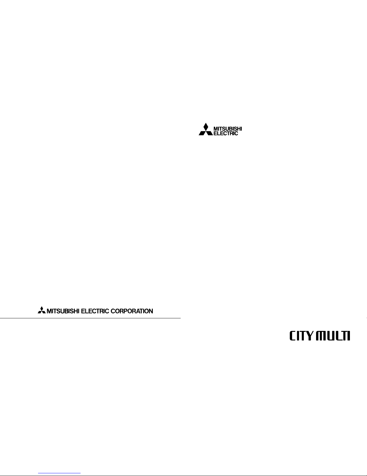
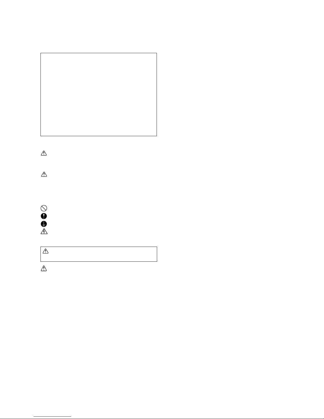
[1] Storage of Piping Material
(1) Storage location
Store the pipes to be used indoors.
Storing them outdoors may cause dirt, waste, or water to infiltrate.
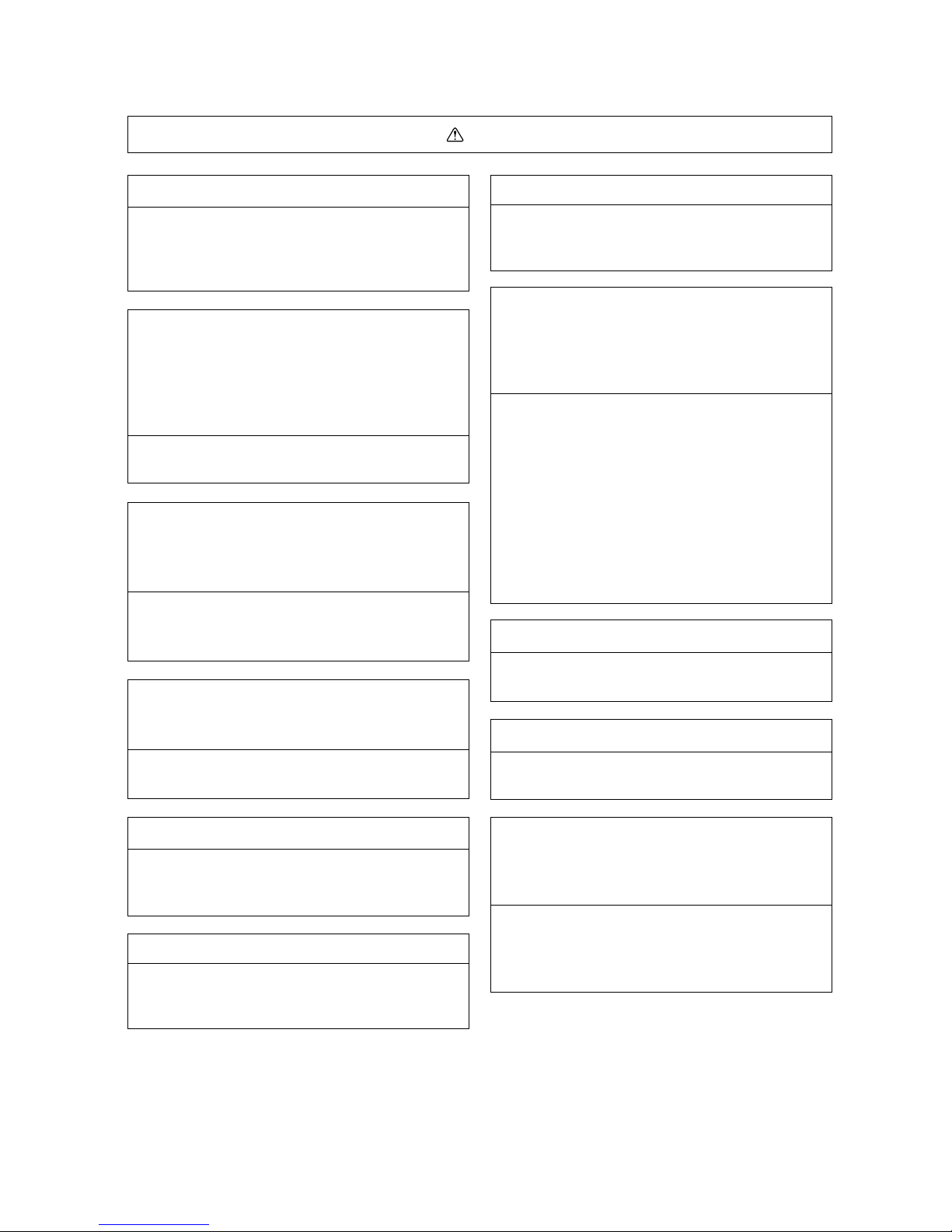
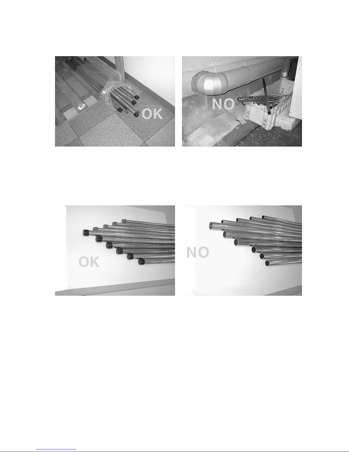
(2) Pipe sealing before storage
Both ends of the pipes should be sealed until immediately before brazing.
Wrap elbows and T’s in plastic bags for storage.
* The new refrigerator oil is ten times more hygroscopic than the conventional refrigerator oil (such as Suniso). Water
infiltration in the refrigerant circuit may deteriorate the oil or cause a compressor failure. Piping materials must be
stored with more care than with the conventional refrigerant pipes.
–5–
Use only the necessary minimum quantity of oil.
Reason :
1. The refrigerator oil used for the equipment is highly hygroscopic and may introduce water inside.
Notes :
• Introducing a great quantity of mineral oil into the refrigerant circuit may also cause a compressor failure.
• Do not use oils other than ester oil, ether oil or alkylbenzene.
[2] Piping Machining
Use a small amount of ester oil, ether oil, or alkylbenzene to coat flange connections.

–6–
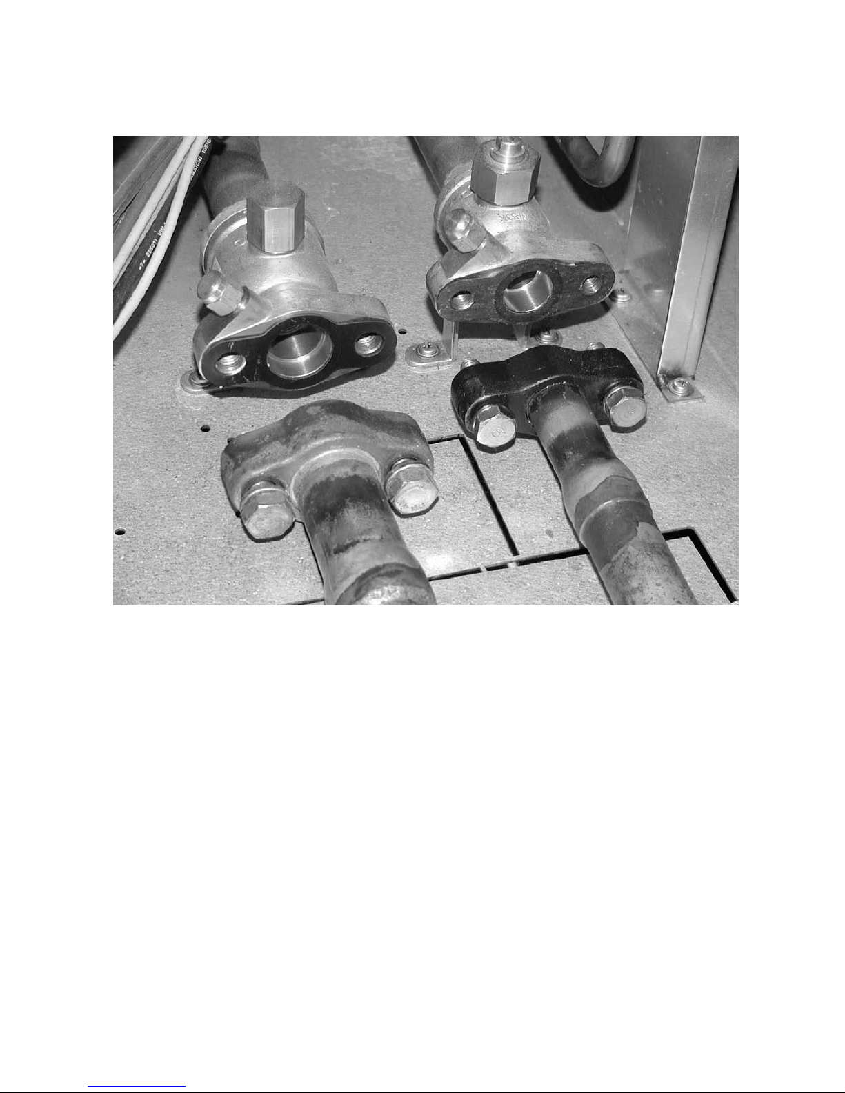
[3] Brazing
No changes have been noted from the conventional method, but special care is required to keep contaminants (i.e. oxide
scale, water, dirt) from entering the refrigerant circuit.
Example : Inside a brazed section
When non-oxide brazing was not used When non-oxide brazing was used
Items to be strictly observed :
1. Do not conduct refrigerant piping work outdoors on a rainy day.
2. Apply non-oxide brazing.
3. Use a brazing material (BCuP-3) which requires no flux when brazing the sections between copper pipes or between
a copper pipe and copper coupling.
4. If installed refrigerant pipes are not immediately connected to the equipment, then braze and seal both ends of them.
Reasons :
1. The new refrigerant oil is ten times more hygroscopic than the conventional oil. The probability of a machine failure
due to water infiltration is higher than with conventional refrigerant oil.
2. A flux generally contains chlorine. A residual flux in the refrigerant circuit may generate sludge.
Note :
• Commercially available antioxidants may have adverse effects on the equipment due to its residue, etc. When
applying non-oxide brazing, use oxygen free nitrogen (OFN).
–7–
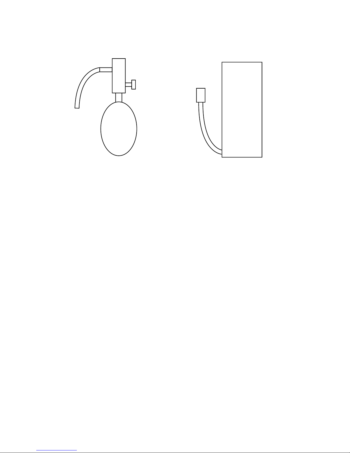
[4] Airtightness Test
No changes from the conventional method. Note that a refrigerant leakage detector for R22 cannot detect R407C
leakage.
Halide torch R22 leakage detector
Items to be strictly observed :
1. Pressurize the equipment with nitrogen up to the design pressure and then check the equipment’s airtightness,
taking temperature variations into account.
2. When investigating leakage locations using a refrigerant, be sure to use R407C.
3. Ensure that R407C is in a liquid state when charging.
Reasons :
1. Use of oxygen as the pressurized gas may cause an explosion.
2. If gas refrigerant is used, the composition of the remaining refrigerant in the cylinder will change and this refrigerant
will become unusable.
Note :
• A leakage detector for R407C is sold commercially, and it should be purchased.
[5] Vacuuming
1. Vacuum pump with check valve
A vacuum pump with a check valve is required to prevent the vacuum pump oil from flowing back into the refrigerant
circuit when the power supply is cut off due to power failure. A check valve may be added to a vacuum pump not
equipped with one.
2. Standard degree of vacuum for the vacuum pump
Use a pump which reaches 0.5 Torr (500 MICRON) or below after 5 minutes of operation.
Be sure to use a vacuum pump that has been properly maintained and oiled with the specified oil. If the vacuum pump
is not properly maintained, desired degree of vacuum may not be achieved.
3. Neccessary accuracy of the vacuum gauge
Use a vacuum gauge that can measure up to 5 Torr. Do not use a general gauge manifold since it cannot measure a
vacuum of 5 Torr.
4. Evacuating time
• Evacuate the equipment for 1 hour after –755 mmHg (5 Torr) has been reached.
• After envacuating, leave the equipment for 1 hour and make sure that the vacuum is not lost.
5. Operating procedure when the vacuum pump is stopped
In order to prevent a backflow of the vacuum pump oil, open the relief valve on the vacuum pump side or loosen the
charge hose to drawn in air before stopping operation.
The same operating procedure should be used when using a vacuum pump with a check valve.
NO
NO
–8–
Cylin-
der
Cylin-
der
Valve
Val ve
Liquid
Liquid
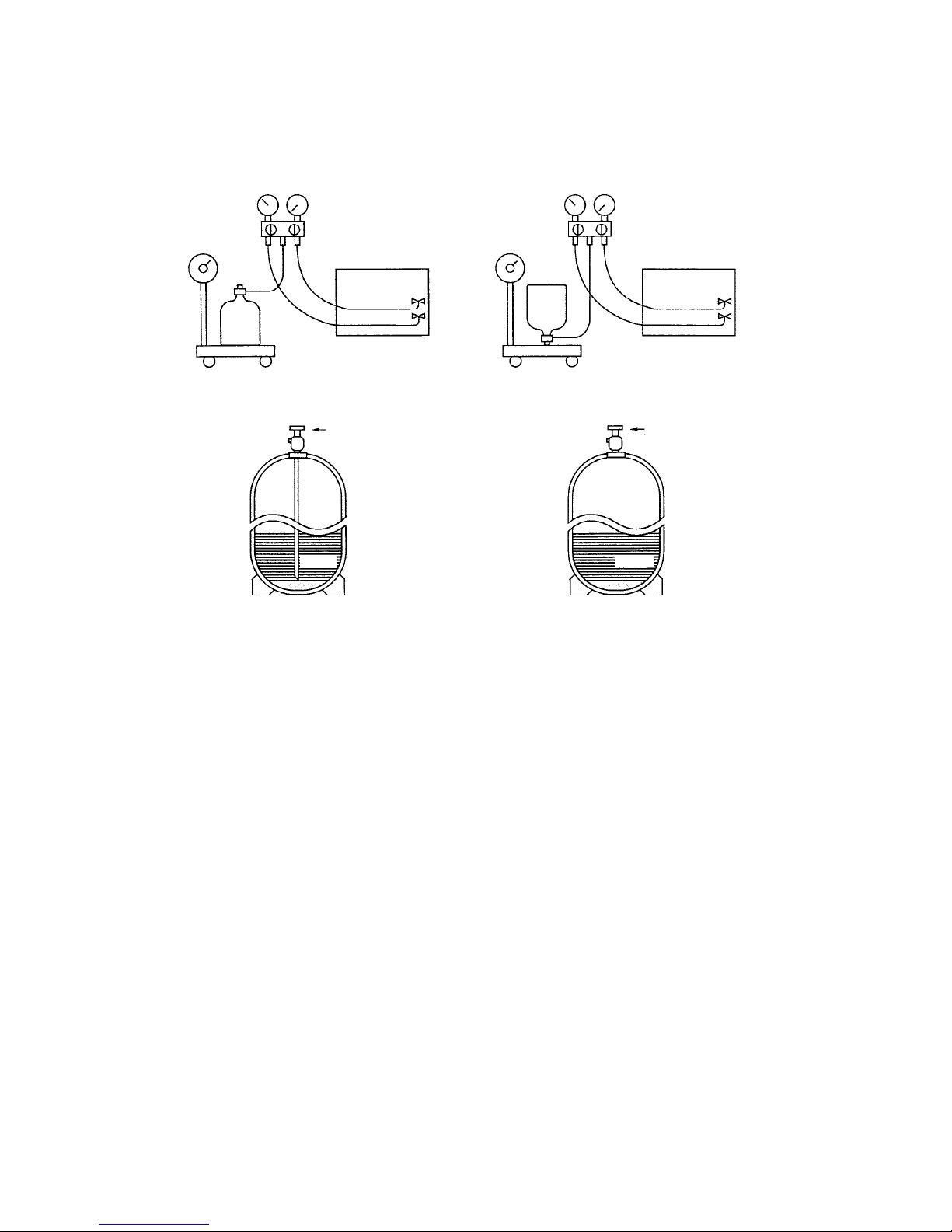
[6] Charging of Refrigerant
R407C must be in a liquid state when charging, because it is a non-azeotropic refrigerant.
For a cylinder with a syphon attached For a cylinder without a syphon attached
Cylinder color identification R407C-Gray Charged with liquid refrigerant
R410A-Pink
Reasons :
1. R407C is a mixture of three refrigerants, each with a different evaporation temperature. If the equipment is charged
with R407C gas, then the refrigerant whose evaporation temperature is closest to the outside temperature is charged
first while the rest of refrigerants remain in the cylinder.
Note :
• Do not use cylinders that are equipped with a siphon upside-down. Check the type of cylinder before charging.
[7] Dryer
1. Replace the dryer when the refrigerant circuit is opened (Ex. Change the compressor, full gas leakage). Be sure to
replace the dryer with a CITY MULTI Series Y (For use with R407C).
The use of any other product will damage the unit.
2. Do not leave the refrigerant circuit open for longer than one hour after removing the old drier.
–9–
22
22
2 COMPONENT OF EQUIPMENT
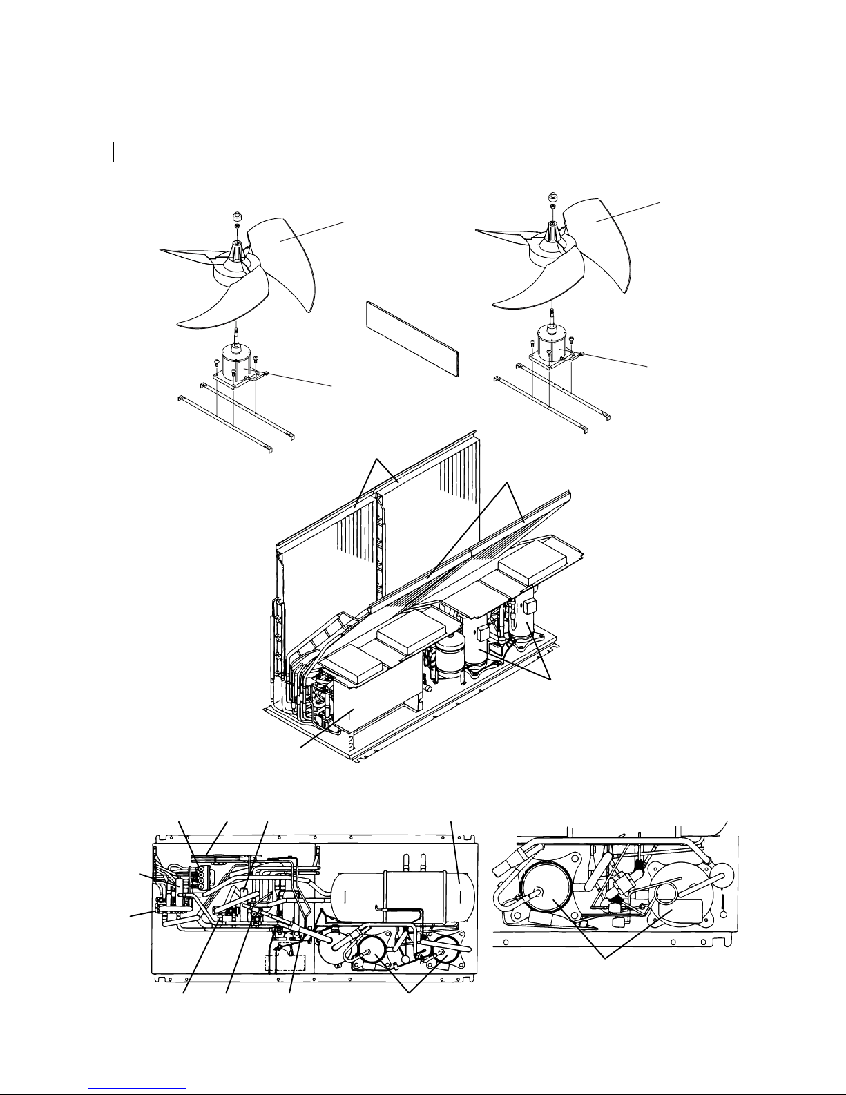
[1] Appearance of Components
Outdoor unit
Heat exchanger(front)
Compressor
Heat exchanger(rear)
SV block 1
SV block 2
4–way
valve
4–way valveCS circuit
Drier
CV
block 1
CV block 2
Control box
Compressor
Compressor
P500 TYPEP400 TYPE
Accumulator
Propeller fan
Fan motor
Propeller fan
Fan motor
–10–
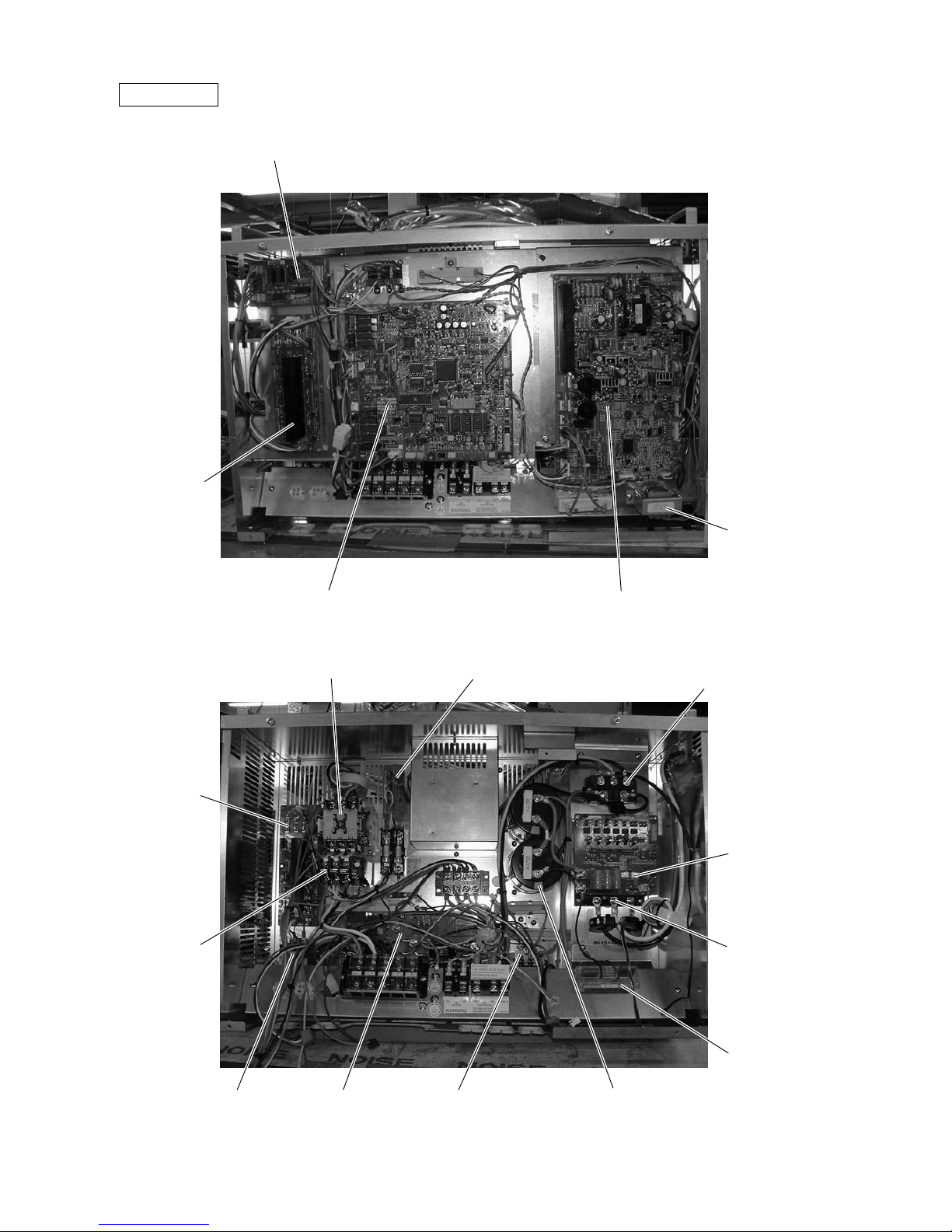
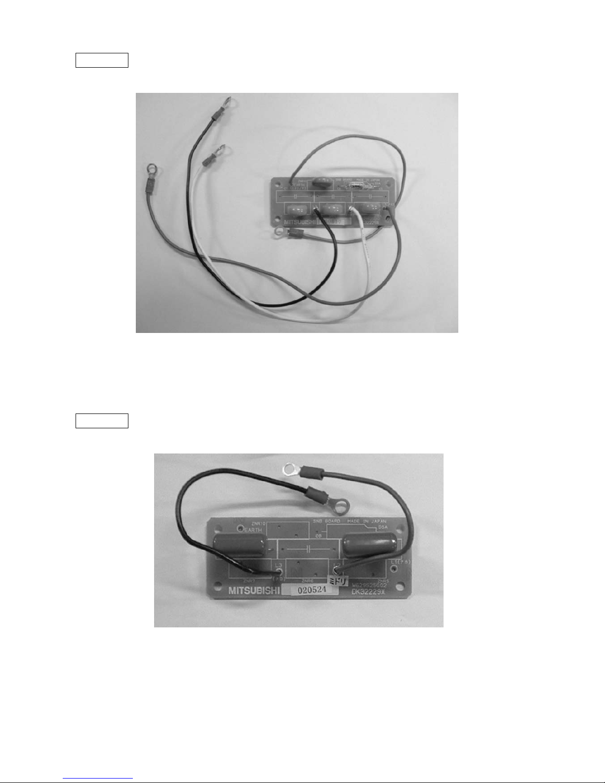
Controller Box
RELAY board
FANCON board
(for MF3)
INV boardMAIN board
Choke coil (L2)
Intelligent Power
Module (IPM)
G/A board
Y-C board
SNB board
Diode stack (DS)
Magnetic contactor (52C2)
Magnetic contactor (52C1)Magnetic contactor
(52F)
Overload relay
(51C2)
FANCON board
(for MF2)
Capacitor (C2, C3)
(Smoothing capacitor)
Noise filter
(NP)
–11–
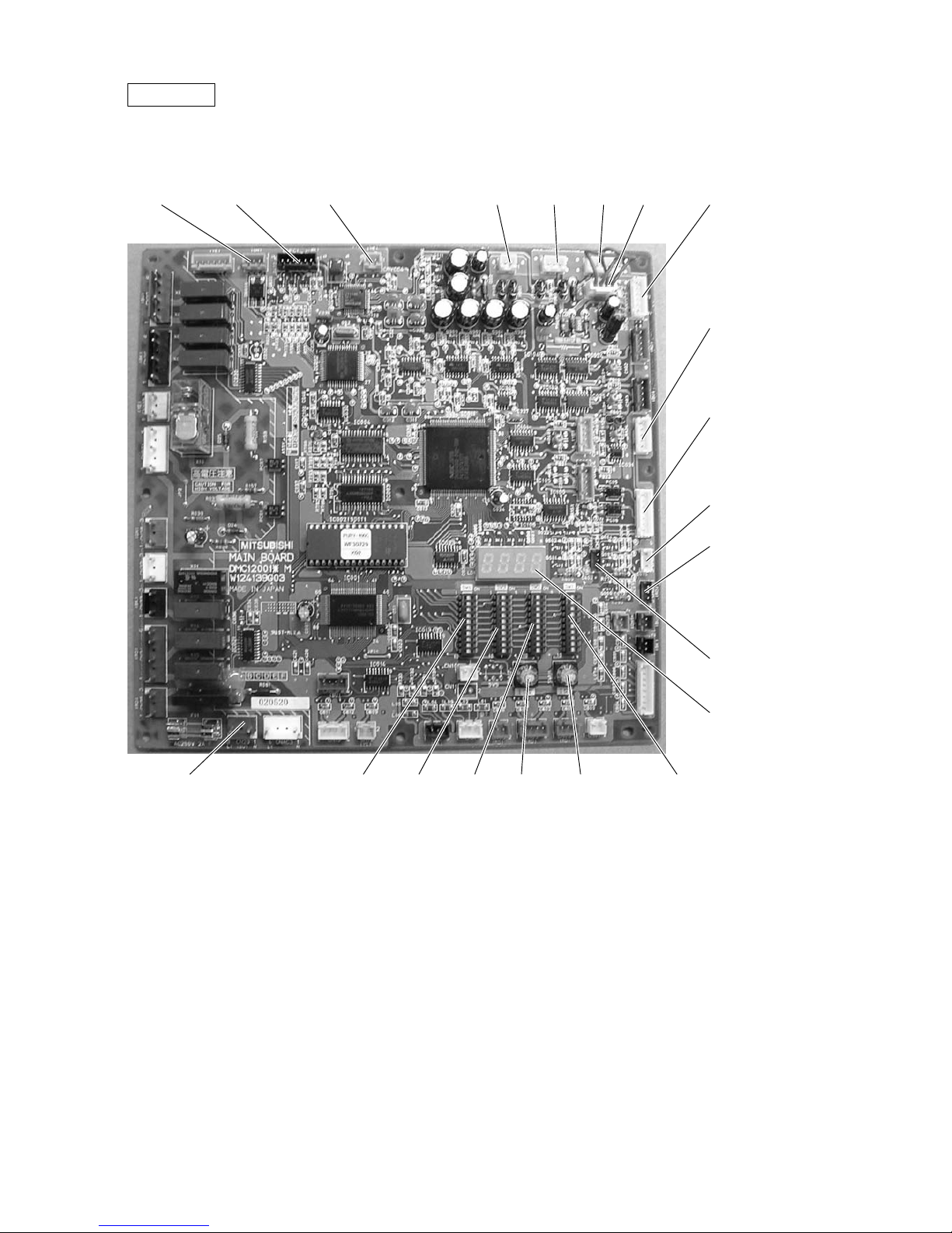
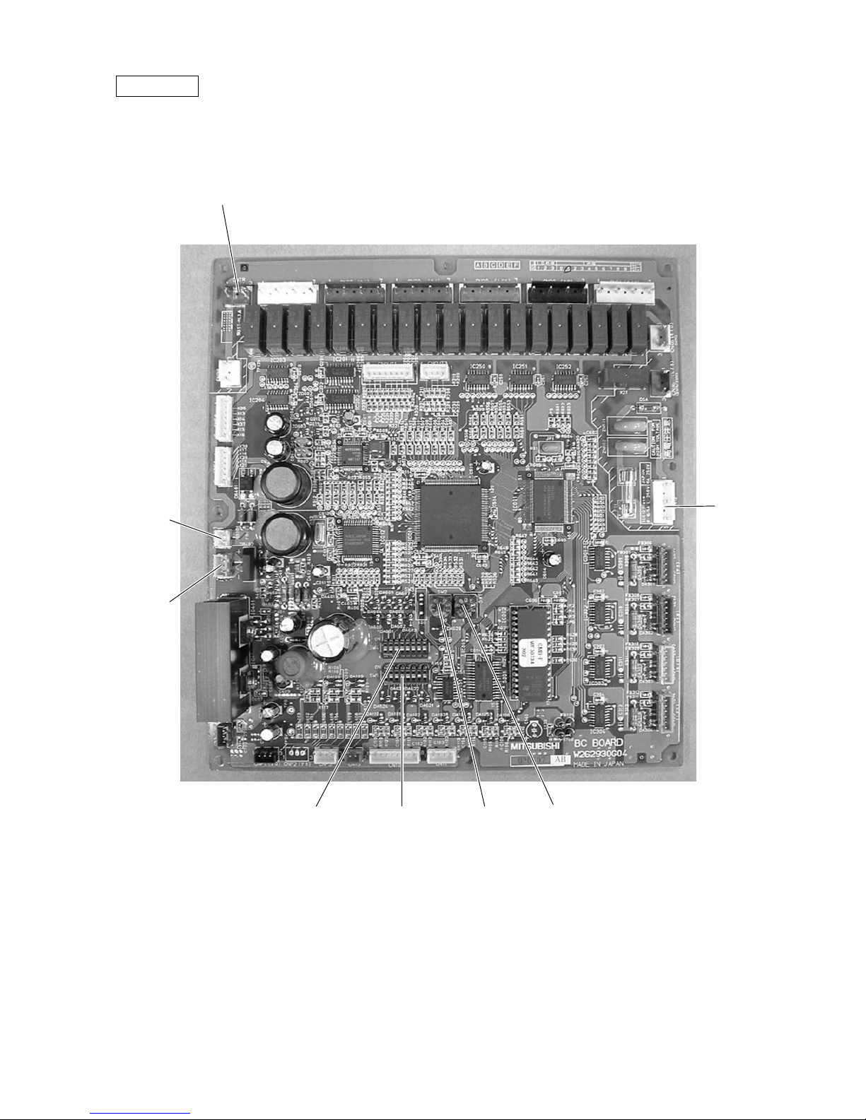
MAIN board
• PURY
CN51
Indication distance
3-4 Compressor
ON/OFF
3-5 Error Indicator
CNRS3
Serial transmission to
INV board
CN3D
SW1
CNTR CNFC1
CNVCC4
Power source
for control(5V)
CN20
Power supply
3 L1
1 N
SW3SW4 SW2 SWU2 SWU1
CNS1 CNS2
CN40
CNVCC3
Power Source
for control
1-2 30V
1-3 30V
4-6 12V
5-6 5V
CN3S
CN3N
LD1
Service LED
CN41
–12–
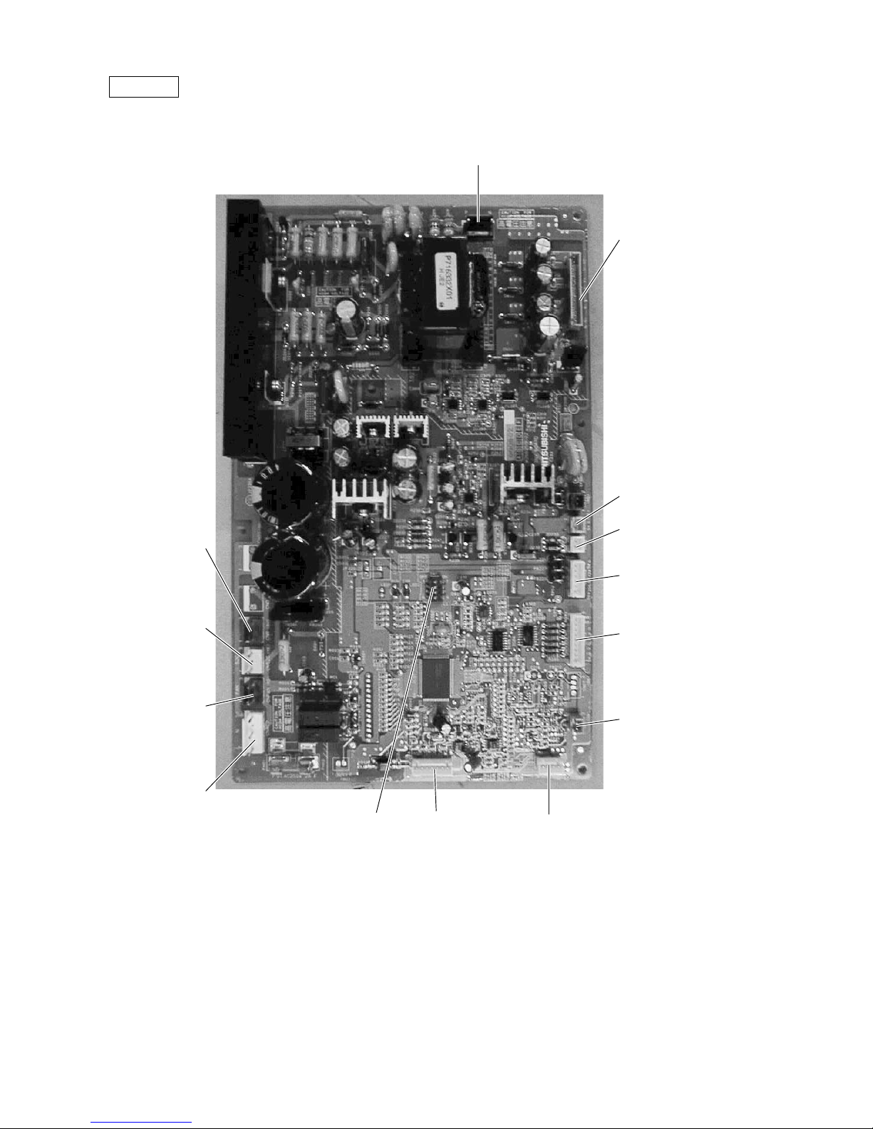
INV board
CNDR2
Output to
G/A board
CNTH
CN15V2
Power supply
for IPM control
CNACCT
CNAC2
Powe r
source
1 L2
3 N
5 G
CN52C
Control for
52C
CNFAN
Control
for MF1
CNR
CNRS2
Serial transmission
to MAIN board
SW1
CNVDC
1-4
DC-560V
CNVCC4
Power supply (5V)
CNL2
Choke coil
CNVCC2
Power supply
1-2 30V, 1-3 30V
4-6 12V, 5-6 5V
–13–
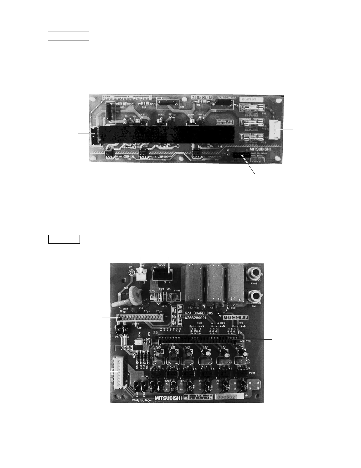
CNFAN
CNPOW
CNFC2
CN15V1
CNDR1
CNIPM1
CNE CNDC1
FANCON board
G/A board
–14–
Y-C board
SNB board
–15–
BC controller
CNTR
CN02
M-NET
transmission
CN03
CN12
Power
supply
1 EARTH
3 N
5 L
SW4 SW2 SW1SW5
–16–
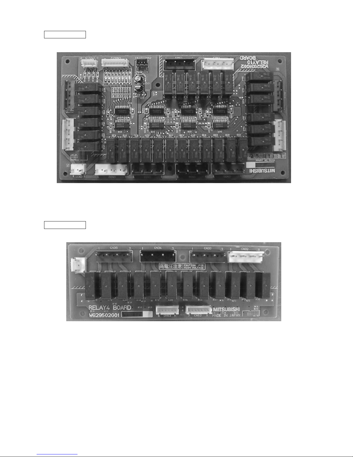
RELAY 10 board
RELAY 4 board
–17–
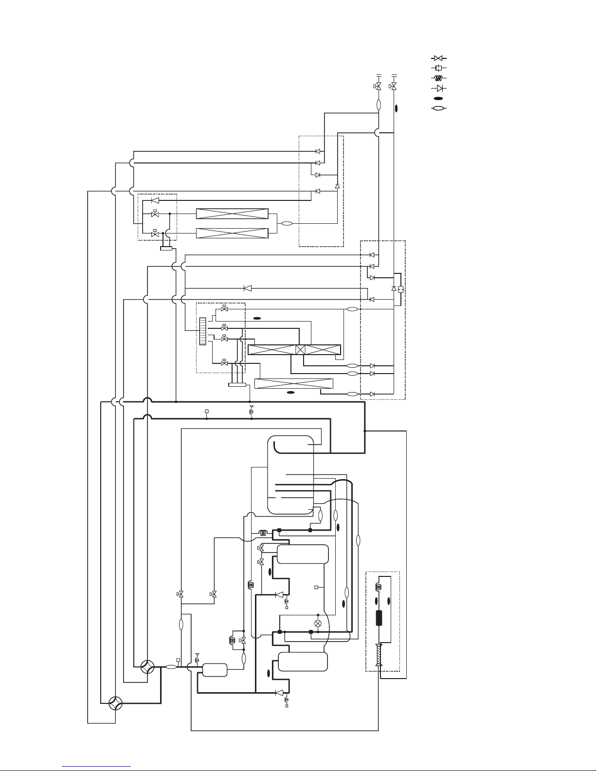
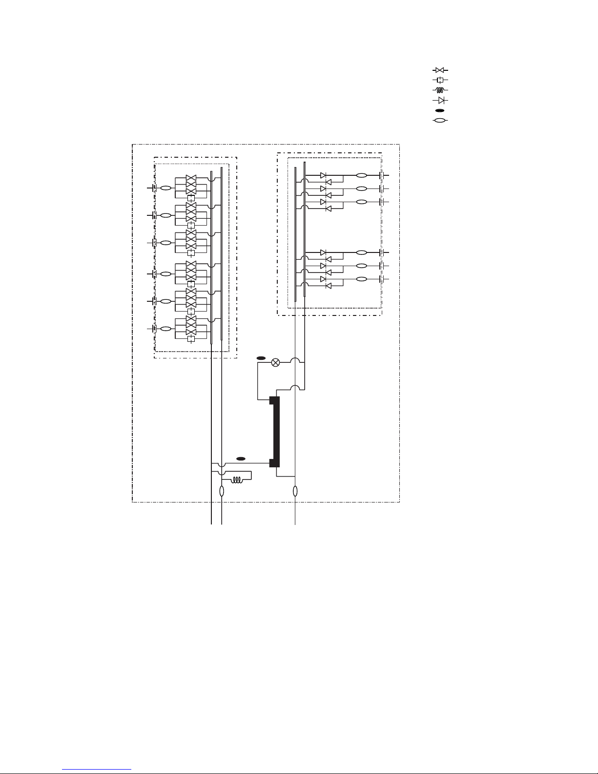
[2] Refrigerant Circuit Diagram and Thermal Sensor
PURY-P400, 500YEM-A
* SV22, SV32 For P500YEM-A only.
: Solenoid valve
: Orifice
: Capillary
: Check valve
: Thermal sensor
: Strainer
SP : Service port
ACC : Accumulator
CV3b
BV1
BV2
ST1
TH5
CV2b
ST15
TH7
TH6
CJ2
MA
SA
CJ3
CJ1
63HS
63H1
O/S
63H2
SLEV
Comp2
Comp1
CV1b
CV1a
SV32
SV22
CP3a
TH12
TH2
TH9
Drier
CP2
TH11
ST9
ST5
ST6
ST2
21S4a
21S4b
ST3
ST4
ST8
TH3
TH4
63LS
HEXf1
HEXf3
HEXb1
HEXf2
ST14
ST13
ST12
ST11
CV5b
CV7b
SV8
SV6
SV5
SV4
SV3
SV7
SV Block 2
SV Block 1
HEXf4
HEXb2
CV4b
CV4a
CV10a
Orifice
CV9a
CV8a
CV3a
CV2a
CV5a
CV6a
CV7a
CV6b
CV Block 2
CV Block 1
*
SV22, 32: P500 only
CP3b
SV4a
SV6a
SV1
CP1
CS Circuit

–18–
CMB-P108, 1010, 1013, 1016V-FA
SVM2
TH16
TH11
TH12
SVM1
PS3
PS1
Check
valve block
Solenoid
valve block
LEV3
LEV1
TH15
Gas/liquid
separator
: Solenoid valve
: Orifice
: Capillary
: Check valve
: Thermal sensor
: Strainer
–19–
CMB-P108V-FB
Check
valve block
LEV3a
TH25
TH22
Solenoid
valve block
CP
: Solenoid valve
: Orifice
: Capillary
: Check valve
: Thermal sensor
: Strainer
–20–
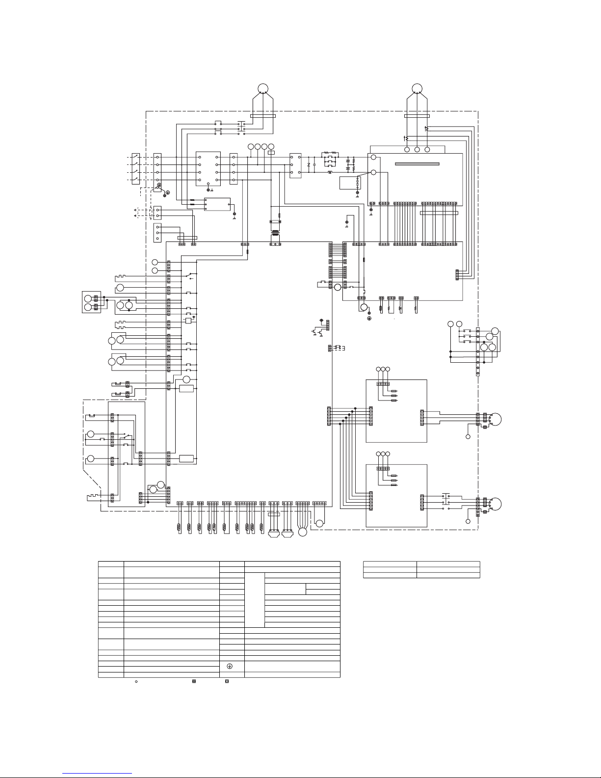
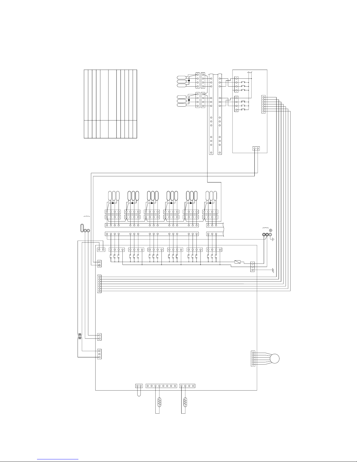
[3] Electrical Wiring Diagram
PURY-P400·500
NOTE : Mark indicates terminal bed, connector, board insertion connector
Symbol N a m e
Choke coil(Transmission)L2 TerminalT1~15
"
✻
1" are not existedPURY-P400
Appliance N a m e
<Difference of appliance>
SV1,22,32, Solenoid valve
4-way valve21S4a,4b
Electronic expansion valve(Oil return)
High pressure sensor
Low pressure sensor63LS
63HS
SLEV
(Heat exchanger capacity control)
Solenoid valve
SV3,4,5,6,
Varistor
N a m eSymbol
DCL
(Power factor improvement)
<Symbol explanation>
DC reactor
ACCT-U,W Current Sensor
ZNR4
FB1~6 Ferrite core
Fan motor (Radiator panel)
(Inverter main circuit)
52C1
MF1
Magnetic contactor
Intelligent power moduleIPM
Discharge pipe temp. detect
Radiator panel temp. detect
Compressor shell temp.
High pressure liquid temp.
OA temp. detect
Pipe temp. detect(Hex outlet)
Saturation evapo. temp. detect
Thermistor
THHS
TH10
TH9
TH6
TH5
TH2
TH11,12
Earth terminal
X1,2,4~13 Aux. relay
TH7
LD Accumulator liquid level detect
52C2
51C2
52F
4a,6a
7,8
TH3
TH4
CH11,12
SSR
CH2,3
63H1,2 High pressure switch
Crank case heater(Compressor)
Magnetic contactor(Fan motor)
PURY-P500 All exists
Magnetic contactor
Overload relay
Accumurator liquid
temp. detect
Lower
Upper
Pipe temp.(Hex inlet)
Solid state relay
Cord heater
L1
L2
L3
EARTH
SNB board
X12
X11
X10
21S4b
SV3
X13
Relay board
TH2TH7TH5TH6TH3TH4
63LS
63HS
TH11
TH9TH10 TH12
SLEV
SV1
SV4a
52C1
CH12
52F
52C2
51C2
CN51C2
(3P)
CN52C2
(5P)
CN52F
(3P)
CNCH
(3P)
CNRT2
(5P)
CNOUT2
(4P)
CNRT1
(5P)
CNOUT1
(6P)
21S4a
SV6a
SV5
MF1
6
5
F5
8A F
600VAC
F6
600VAC
8A F
FB3
1
2
3
CNX10
(3P)
Motor
(Compressor)
52F
1
2
3
4
5
6
L1 L2 L3
(6P)
CNFC1
F01 250VAC 6.3A F
F03 250VAC 6.3A F
F02 250VAC 6.3A F
N
CNPOW
(5P)
CNFC2
(6P)
1
2
3
4
5
6
1
2
3
4
5
6
V
W
N
U
MF3
1
2
3
4
5
1
2
3
4
5123 4
Fan control board
(Fancon board)
(5P)
CNFAN
CN04
F01 250VAC 6.3A F
F03 250VAC 6.3A F
F02 250VAC 6.3A F
N
CNPOW
(5P)
CNFC2
(6P)
1
2
3
4
5
6
V
W
N
U
MF2
1
2
3
4
5
1
2
3
4
5123 4
Fan control board
(Fancon board)
L1 L2 L3
(5P)
CNFAN
FB5
BlackWhite
Red
Controller Box
Inverter
controller
remote
Connect to
Indoor and
Crank case heater
(Compressor)
circuit
detection
circuit
detection
High pressure
switch
(MAIN board)
Control circuit board
Refer to the service handbook
about the switch operations.
5:Trouble
4:Compressor ON/OFF
DEMAND
NIGHT MODE
(INV board)
Power circuit board
Gate amp board
(G/A board)
BlackWhite
Red
Motor
(Compressor)
Diode
stack
Noise
Filter
Terminal
Block
Terminal
Block
BOX BODY
BOX BODY
BOX BODY
BOX BODY
BOX BODY
X10
2A F
1A F
2A F
CNAC3
(4P)
A
B
4
3
2
1
(3P)
CN20
DS
CNTR1
123
T01
F3
250VAC
CNTR
(3P)
L1 L2 L3 N
L1
TB1B
L2
L3NNL3
L2
L1
N
L3
L2
NF
L1
N
L3
L2
TB1A
L1
PE
PE
N
L3
L2
L1
Red
White
Black
12345
CNLV4
(5P)
123
(3P)
CN03
1234
CN05
(4P)
CNE
(2P)
21
(14P)
CN15V2
(7P)
CNRS3
(6P)
CNVCC2
(6P)
CNVCC3
(2P)
CNVCC4
(7P)
CNRS2
X01
3
2
1
6
5
1
2
3
4
5
6
7
1
2
1
4
3
2
9876432112
3
V
MC1
W
U
(4P)
CNVDC
(3P)
CN52C
(5P)
CNAC2
(2P)
CNVCC4
250VAC
F01
6
5
1
2
3
4
5
6
7
1
2
1
4
3
2
CNDC1
(4P)
1234
12345987612345
CNDR2
(9P)
14131110 12
121011 13 14
543216789 54321 6789
5
1
2
3
4
UVW
P
N
IPM
CNDR1
(9P)
CN15V1
(14P)
4
CNACCT
(4P)
543121678312 1 23 1 23 1234 5
2
3
4
2
5
1
3
CN33
(3P)
1
1
CN3D
(3P)
322
3
2
21131
CNS1
(2P)
CN51
(5P)
2
CNS2
(3P)
X02
X01
12V
F1
250VAC
123
Black
White
Red
123
TB3
TB7
ZNR4
C1
R5
R1
52C1
+
+
DCL
C2
C3
R2
R3
CN02
(8P)
CN01
(2P)
CNH
(3P)
CNL
(3P)
CN32
(3P)
CNLV1
(5P)
CN06CN09
12
(2P)
12
(2P)
CN37
(6P)
6
5
4
3
2
1
X09
CN36
(6P)
6
5
4
3
2
1
X06
X07
X05
(3P)
CN38
3
2
1
1
2
3
4
5
6
(6P)
CN34
(2P)
CN07
21
U
W
MC2
V
1
3
5
6
4
2
6
5
4
3
2
1
52C2
51C2
-W
ACCT
-U
ACCT
M1
M2
S
M1
M2
1
2
3
4
5
1
2
3
4
5
6
1
2
3
4
5
4
1
2
3
X02
X03
3
2
1
1
2
3
5
4
1
2
3
1
2
3
52C2
X01
9695
A2A1
1314
A1A2
(3P)
CN35
3
2
1
12
34
SSR
CH2
CH3
CH11
X04
X08
CNFAN
(3P)
321
X02
L2
R7
THHS
R6
(2P)
CN30V
(2P)
CNL2
12 1 23 12 12
(2P)
CNTH
(3P)
CNR
BOX BODY
FB2FB1
FB4
FB6
T1
T2
T3
T4
T5
T6
T9
BOX BODY
T15
T13
SV22
SV32
T12
T14
63H2
63H1
T11
T10
T8
T7
8
7
6
5
4
3
2
1
A B
SV8
X12
SV4
SV6
SV7
X13
X11
CN06
Y-C
board
CN05
Fan motor
(Heat exchanger)
Fan motor
(Heat exchanger)
Power source
380/400/415V
50/60Hz
✻
1
3N~
+
~
-~
~
–21–
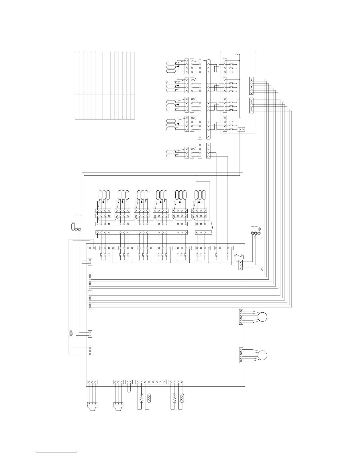
CMB-P108·1010V-FA
5
1
2
34
4
1
2
3
1
2
3
1
2
3
SVM1
SVM2
131415
9
101112
5
6
78
4
4
5
6
87
9
12 11 10
15 14 13
16
16
1
2
3
4
1
2
3
4
1
2
3
4
1
2
3
4
1
2
3
4
1
2
3
4
1
2
3
4
1
2
3
4
SV7B
SV8B
SV9B
SV10B
SV7A
SV8A
SV9A
SV10A
SV7C
SV8C
SV9C
SV10C
SV1B
SV1A
SV1C
1
5
6
7
8
9
10
11
12
13
14
15
16
3
2
4
8
9
10
11
12
13
3
2
4
1
5
6
7
14
15
16
4
3
2
1
SV2C
SV2A
SV2B
SV3C
SV3A
SV3B
SV4C
SV4A
SV4B
SV5B
SV5A
SV5C
4
3
2
1
4
3
2
1
4
3
2
1
4
3
2
1
4
3
2
1
4
3
2
1
4
3
2
1
4
3
2
1
4
3
2
1
SV6B
SV6A
SV6C
1
2
3
4
1
2
3
4
33
2
1
2
1
X60
X21
CN46
CN36
3
1
3
1
Power source
L
N
~220V~240V 50/60Hz
Transmission line
Shield wire
CONT.board
CN38
1
3
1
CNTR
CN50CN51
7654321123456
CN02
CN12
13
7
5
3
1
7
5
3
1
7
5
3
1
7
5
3
1
7
5
3
1
7
5
3
1
3
TR
X2
X1
X30
X4
X3
X31
X6
X5
X32
X8
X7
X33
X10
X9
X34
X12
X11
X35
DC 30V
6
54
3
2
1
6
54
3
2
1
LEV3 LEV1
1
2
3
CNP1
1
2
3
CNP3
2
1
1
2
3
4
5
6
7
8
4
3
2
1
12321
CN03
CN13
CN10
CN11
CN07 CN05
TH11
TH12
TH15
TH16
PS1
PS3
22V
TB02
M2
M1
CN26
CN27
CN28
CN29
CN30
CN31
TB01
220~240V
LEV1
7654321123456
CN35
TB01
RELAY4 Board
CN32
CN33
CN34
CN39
3
1
X14
X13
X36
X37
X15
X16
X18
X17
X38
X39
X19
X20
CN52CN53
57317531753175133 3
F01
250VAC
6.3A F
T8T9
T7
T10
T1
T5
T4
T3
T2
T6
PE
3
2
1
3
2
1
EARTH
Fuse AC250V 6.3A F
F01
Terminal
T1 ~ 10
SVM1, 2
Solenoid valve
TB02
TB01
Terminal block
(for Transmission)
Solenoid valve
Solenoid valve
Solenoid valve
Terminal block
(for power source)
Pressure sensor
Expansion valve
Thermistor sensor
Transformer
NameSymbol
SV1 ~ 10A
SV1 ~ 10B
SV1 ~ 10C
TR
TH11, 12, 15, 16
LEV1, 3
PS1, 3
Note1: Never connect the power line to the
terminal block for transmission (TB02)
<
Symbol explanation
>
–22–
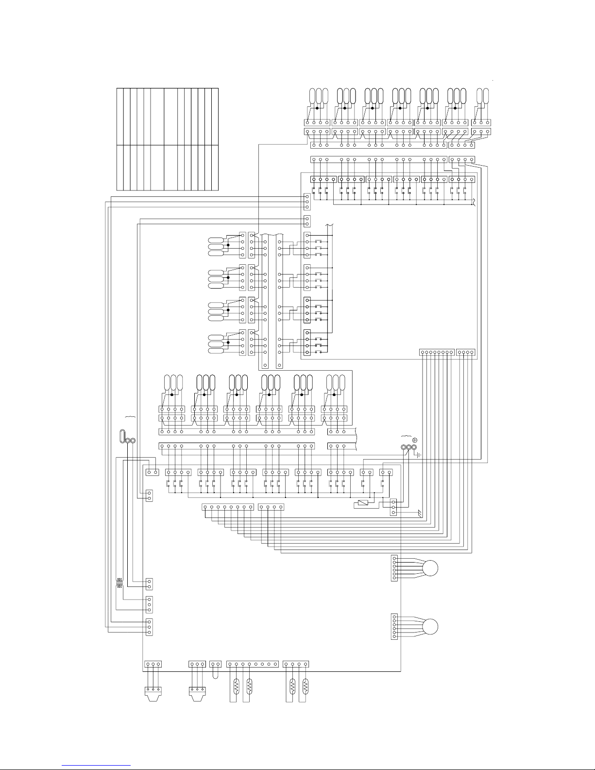
CMB-P1013·1016V-FA
3
2
1
Power source
L
TB01TB01
N
~220V~240V 50/60Hz
1
2
3
SVM2
SVM1
1
3
2
8
8
9
9
10
10
11
11
12
12
13
13
3
2
4
4
1
5
5
6
6
7
7
14
14
15
15
16
16
4
3
2
1
4
3
2
1
4
3
2
1
4
3
2
1
4
3
2
1
4
3
2
1
4
3
2
1
4
3
2
1
4
3
2
1
4
3
2
1
1
2
3
4
1
2
3
4
3
3
4
4
2
2
1
1
SV11B
SV11A
SV11C
SV16C
SV16A
SV16B
SV15C
SV15A
SV15B
SV14C
SV14A
SV14B
SV13C
SV13A
SV13B
SV12C
SV12A
SV12B
131415
9
101112
5
6
78
4
4
5
6
87
9
12 11 10
15 14 13
16
16
1
2
3
4
1
2
3
4
1
2
3
4
1
2
3
4
1
2
3
4
1
2
3
4
1
2
3
4
1
2
3
4
SV7B
SV8B
SV9B
SV10B
SV7A
SV8A
SV9A
SV10A
SV7C
SV8C
SV9C
SV10C
SV1B
SV1A
SV1C
1
5
6
7
8
9
10
11
12
13
14
15
16
3
2
4
8
9
10
11
12
13
3
2
4
1
5
6
7
14
15
16
4
3
2
1
SV2C
SV2A
SV2B
SV3C
SV3A
SV3B
SV4C
SV4A
SV4B
SV5B
SV5A
SV5C
4
3
2
1
4
3
2
1
4
3
2
1
4
3
2
1
4
3
2
1
4
3
2
1
4
3
2
1
4
3
2
1
4
3
2
1
SV6B
SV6A
SV6C
1
2
3
4
1
2
3
4
33
2
1
2
1
3
1
3
1
CN36
CN46
X21
X60
Transmission line
Shield wire
1
2
3
8
7
6
5
4
3
2
1
4
CNTR
1
3
220~240V
CN35
CN31
CN30
CN29
CN28
CN27
CN26
CN38
M1
M2
TB02
TR
22V
PS3
PS1
TH16
TH15
TH12
TH11
CN32
7531
CN33
CN34
33
CN05CN07
CN11
CN10
CN13
CN02
CN03
12321
1
2
3
4
8
7
6
5
4
3
2
1
1
2
CNP3
3
2
1
CNP1
3
2
1
LEV1LEV3
1
2
3
45
6
1
2
3
45
6
DC 30V
X35
X11
X12
X34
X9
X10
X33
X7
X8
X32
X5
X6
X31
X3
X4
X30
X1
X2
X14
X13
X36
X37
X15
X16
21
CNVCC1
3
X38
X39
X17
X19
X18
X20
X45
X42
X43
X40
X44
X41
CN40
CN41
CNOUT4
CNOUT2
4
1
2
3
4
5
6
7
8
3
2
1
X48
X51
X47
X46
X50
X49
CN43
CN42
CN44
CN45
X55
X56
X52
X53
X57
X54
3
CNVCC2
12
31
753175317531
1
3
5
7
7
5
3
1
7
5
3
1
7
5
3
1
7
5
3
1
7
5
3
1
7
5
3
1
7
5
3
1
7
5
3
1
7
5
3
1
7
5
3
1
7
5
3
1
CNOUT1
CNOUT3
CN12
53
1
31
CN39
CONT.board
RELAY10 board
F01
250VAC
6.3A F
PE
EARTH
T16
T15
T14
T13
T12
T11
T8T9
T7
T10
T1
T5
T4
T3
T2
T6
3
2
1
3
2
1
Terminal
T1
~
16
Solenoid valve
SVM1, 2
PS1, 3
SV1
~
16A
SV1
~
16B
SV1
~
16C
Fuse AC250V 6.3A FF01
Symbol
Name
Pressure sensor
Terminal block
(for power source)
Solenoid valve
Solenoid valve
Solenoid valve
Terminal block
(for Transmission)
TB01
TB02
<
Symbol explanation
>
Transformer
Thermistor sensor
Expansion valve
TR
LEV1, 3
TH11, 12, 15, 16
Note1: Never connect the power line to the terminal
block for transmission (TB02)
–23–
CMB-P108V-FB
131415
9
101112
5
6
78
4
4
5
6
87
9
12 11 10
15 14 13
16
16
1
2
3
4
2
3
4
1
2
3
4
1
2
3
4
SV7B
SV8B
SV7A
SV8A
SV7C
SV8C
1
SV1B
SV1A
SV1C
1
5
6
7
8
9
10
11
12
13
14
15
16
3
2
4
8
9
10
11
12
13
3
2
4
1
5
6
7
14
15
16
4
3
2
1
SV2C
SV2A
SV2B
SV3C
SV3A
SV3B
SV4C
SV4A
SV4B
SV5B
SV5A
SV5C
4
3
2
1
4
3
2
1
4
3
2
1
4
3
2
1
4
3
2
1
4
3
2
1
4
3
2
1
4
3
2
1
4
3
2
1
SV6B
SV6A
SV6C
1
2
3
4
1
2
3
4
33
2
1
2
1
Power source
L
N
~220V~240V 50/60Hz
Transmission line
Shield wire
CONT.board
CN38
1
3
1
CNTR
CN50
7654321
CN02
CN12
1
53
7
5
3
1
7
5
3
1
7
5
3
1
7
5
3
1
7
5
3
1
7
5
3
1
3
TR
X2
X1
X30
X4
X3
X31
X6
X5
X32
X8
X7
X33
X10
X9
X34
X12
X11
X35
DC 30V
6
54
3
2
1
LEV3
2
1
1
2
3
4
5
6
7
8
4
3
2
1
12321
CN03
CN13
CN10
CN11
CN07
TH12
TH15
22V
TB02
M2
M1
CN26
CN27
CN28
CN29
CN30
CN31
TB01
220~240V
7654321
TB01
RELAY4 Board
CN32
CN33
CN39
3
1
X14
X13
X36
X37
X15
X16
CN52
75317513
F01
250VAC
6.3A F
T8
T7
T1
T5
T4
T3
T2
T6
PE
EARTH
F01
Fuse AC250V 6.3A F
Terminal
T1
~
8
TB02
TB01
Terminal block
(for Transmission)
Solenoid valve
Solenoid valve
Solenoid valve
Terminal block
(for power source)
Expansion valve
Thermistor sensor
Transformer
Name
Symbol
SV1
~
8A
SV1
~
8B
SV1
~
8C
TR
TH12, 15
LEV3
Note1: Never connect the power line to the
terminal block for transmission (TB02)
<
Symbol explanation
>
–24–
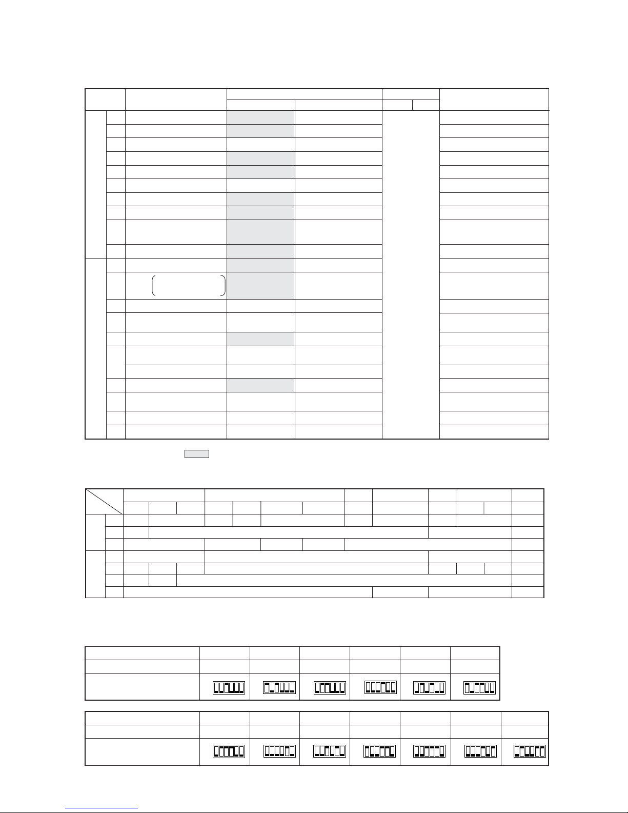
[4] Standard Operation Data
1 Cooling operation
100 100 100 50 50 125 125 125 100 25
10 10 10 10 10 10 10 10 10 10
Hi Hi Hi Hi Hi Hi Hi Hi Hi Hi
360 360 360 340 340 410 410 410 360 280
Discharge (TH11/TH12)
Heat exchanger outlet (TH5)
Inlet
Accumulator
Outlet
Suction (Comp) (No.1/No.2)
Low pressure saturation
temperature (TH2)
Upper (TH4)
Liquid level
Lower (TH3)
Shell bottom (Comp No.1/No.2)
CS circuit (TH9)
Circulating refrigerant
configuration (αOC)
LEV inlet
Heat exchanger outlet
DB/WB
Set
-
m
-
kg
A
V
Pulse
Outdoor
unit
Indoor
unit
Outdoor unit
Items
Ambient temp.
Indoor unit
Piping
Condition
Indoor
Outdoor
No. of units
No. of units in operation
Model
Main pipe
Branch pipe
Total piping length
Outdoor unit
Sectional temperature
Pressure
LEV opening
Indoor unit fan notch
Refrigerant volume
Total electrical current
Voltage
Indoor unit
BC controller (1, 3)
Oil return (SLEV)
380/400/415 380/400/415
P400 P500
High pressure/Low pressure
(after O/S) (before MA)
MPa
°C
92/102 97/102
42
45
67
6/12 12/12
1
30
1
60/51 65/50
16
0.23
26
12
2.11/0.43 2.11/0.42
2.01/2.01 2.01/2.01
BC
controller
High/Intermediate
27.0/19 27.0/19
35.0/24.0 35.0/24.0
55
55
55
55 55
27.1 29.2
26.7/25.4/24.5 33.5/31.9/30.7
2000 300 2000 350
200 344
–25–
Sectional temperature
2 Heating operation
Discharge (TH11/TH12)
Heat exchanger inlet (TH5)
Inlet
Accumulator
Outlet
Suction (Comp) (No.1/No.2)
Low pressure saturation
temperature (TH2)
Upper (TH4)
Liquid level
Lower (TH3)
Shell bottom (Comp No.1/No.2)
CS circuit (TH9)
Circulating refrigerant
configuration (αOC)
LEV inlet
Heat exchanger outlet
100 100 100 50 50 125 125 125 100 25
10 10 10 10 10 10 10 10 10 10
Hi Hi Hi Hi Hi Hi Hi Hi Hi Hi
600 600 600 450 450 650 650 650 600 350
DB/WB
Set
-
m
-
kg
A
V
Pulse
Outdoor unit
Items
Ambient temp.
Indoor unit
Piping
Condition
Indoor
Outdoor
No. of units
No. of units in operation
Model
Main pipe
Branch pipe
Total piping length
Outdoor
unit
Indoor
unit
Outdoor unit
Pressure
LEV opening
Indoor unit fan notch
Refrigerant volume
Total electrical current
Voltage
Indoor unit
BC controller (1, 3)
Oil return (SLEV)
380/400/415 380/400/415
P400 P500
2.01/1.72 2.01/1.72
MPa
°C
High pressure/Low pressure
(after O/S) (before MA)
88/93 88/93
– 3 – 1
– 6 – 7
– 6 – 7
– 5/2 – 5/0
– 10
30
– 6
43/45 40/33
5
0.28
81
34
2.11/0.35 2.11/0.31
BC
controller
High/Intermediate
20.0/- 20.0/-
7.0/6.0 7.0/6.0
55
55
55
55 55
27.1 29.2
24.6/23.4/22.5 30.8/29.2/28.2
60 1400 60 1600
122
–26–
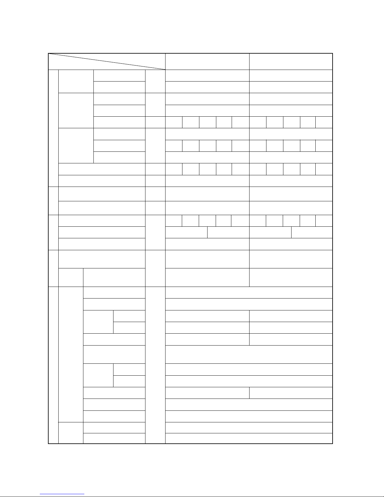
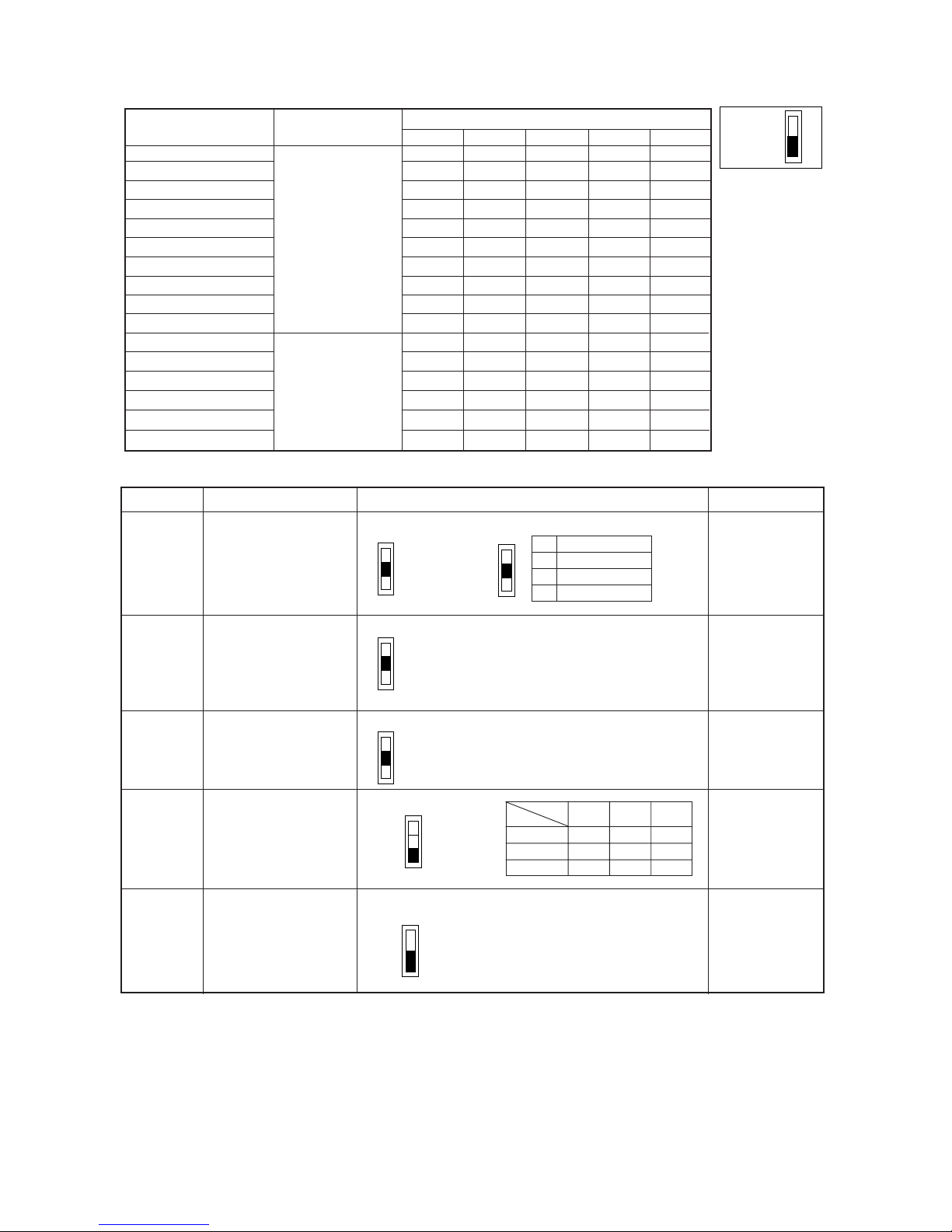
Function According to Switch Operation Switch Set Timing
When Off When On When Off When On
SWU 1 ~ 2
SW1
1 ~ 8
Refer to LED monitor display on the outdoor board.
9 ~ 10
SW2
1
2
3
4
5
6
7
8
9
10
SW3
1
2
3
4
5
6
7
8
9
10
SW4
1
2
3
4
5
6
7
8
9
10
Centralized control not
connected.
Storing of refrigeration
system connection
information.
Store IC•OC error history.
Ordinary control
-
Ordinary control
-
-
SW3-2 Function Invalid
Stop all indoor units.
– 8°C
7°C
Ordinary control
Ordinary control
Ordinary control
-
-
Model 400
SW4-2 Function invalid
-
-
-
-
-
-
-
-
[5] Function of Dip SW and Rotary SW
(1) Outdoor unit
1 Variable capacity unit
MAIN board
Centralized control
connected.
Deletion of refrigeration
system connection
information.
Erase IC·OC error history.
• Refrigerant volume
adjustment operation.
• Ignore liquid level errors
-
Start forced defrosting.
-
-
SW3-2 Function Valid
Test run all indoor units
test run ON.
– 10°C
12°C
2deg lower than normal
Pump Down Operation
High pressure / 1.5 ~ 2.5 K
higher than normal
-
-
Model 500
SW4-2 Function valid
-
-
-
-
-
-
-
-
Changes as shown below by on → off change
0 %→3 %→6 %→9 %→12 %→ – 6 %→ – 3 %→0 %
Unit Address Setting
For self-diagnosis/
operation monitoring
Centralized Control
Switch
Deletion of connection
information.
Deletion of error history.
• Adjustment of Refrigerant Volume
• Ignore liquid level errors
-
-
Forced defrosting
-
-
SW3-2 Function Valid/
Invalid
Indoor Unit Test Operation
Defrosting starting
temperature.
Defrosting ending
temperature.
Target low-pressure
change
Pump Down Function
Target high-pressure
change
-
-
Models
SW4-2 Function valid/
Invalid
Configuration compensation value
-
-
-
-
-
-
-
-
Switch Function
During normal
operation with
power on
Invalid 2 hours
after compressor
starts.
Before power is turned on.
-
Before power is turned on.
Before power is turned on.
During normal operation with
power on
-
-
-
-
During normal operation with
power on.
When SW3-1 is ON after power is
turned on.
During normal operation with
power on.
During normal operation with
power on. (Except during defrosting)
During normal operation with
power on.
While the compressor is stopped.
During normal operation with
power on.
-
When switching on the power.
When switching on the power.
When SW4-1 is ON
-
-
-
-
-
-
-
-
During normal
operation with
power on.
10 minutes or
more after
compressor
starts.
Set on 51 ~ 100 with the rotary switch.*2
Note 1: Factory setting is SWU 1 to 2 = 00, SW3 - 10 = set by model. All other switches are set to OFF.
Note 2: If the address is set from 01 to 50, it automatically becomes 100.
–27–
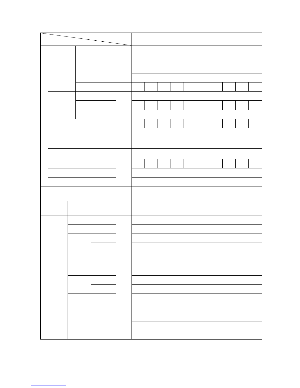
(2) Indoor unit
DIP SW1, 3
Model P71 P80 P100 P125 P140 P200 P250
Capacity (model name) code
14 16 20 25 28 40 50
SW2 setting
Model P20 P25 P32 P40 P50 P63
Capacity (model name) code
45 681013
SW2 setting
ON
OFF
ON
OFF
ON
OFF
ON
OFF
ON
OFF
ON
OFF
ON
OFF
ON
OFF
ON
OFF
ON
OFF
ON
OFF
ON
OFF
ON
OFF
Note 1: The shaded part indicates the setting at factory shipment. (For the SW not being shaded, refer to the
2: When both SW1-7 and SW1-8 are set to ON, the fan stops at the heating thermostat of OFF.
table belo
Note 3: Changes to SW1, 2, 3, and 4 are only registered/effective when the remote controller is off.
Resetting of the power sourse is not required.
w.)
Setting of DIP SW2
Indoor unit inlet
None
100h
Ineffective
Fan output display
At stationary heating
Very low speed
SW1-7 setting
Ineffective
Ineffective
Heat pump
None
None
None
1st setting
Down blow B, C
Effective
–
Effective
–
–
Built in remote controller
Provided
2500h
Effective
Thermo. ON signal display
Always in heating mode
Low speed
Set airflow
Effective
Effective
Cool.only
Provided
Provided
Provided
2nd setting
Horizontal
–
Ineffective
Ineffective
–
–
Room temp. sensor position
Clogged filter detect.
Filter duration
OA intake
Remote display select.
Humidifier control
Heating thermo. OFF airflow
Heating thermo. OFF airflow
Power failure automatic
return
Power source start/stop
Model selection
Louver
Vane
Vane swing function
Vane horizontal angle
V
Vane first angle
ane angle set for cooling
–
Heating 4deg up
–
–
Alw
PLFY-VLMD-B only
ays ineffective for PKFY-P.VAM
Not provided for PKFY-P.VAM
Provided for PLFY-P.VGM (ON) setting
Always down blow B,C for PKFY-P.VAM
Horizontal (ON) setting for PLFY-P. VLMD-A
Ineffective (ON) setting for floor
standing
SW1
SW3
1
2
3
4
5
6
7
8
9
10
1
2
3
4
5
6
7
8
9
10
Switch SW name
Operation by SW
Switch set timing
OFF ON OFF ON
Remarks
At unit stopping
(at remote
controller OFF)
Cooling capacity saving
for PKFY-P. VAM,
effective/ineffective
Model
Switch
SW1
SW3
3
6
7
3
4
6
8
PLFY-P
VAM-A(2)
OFF
OFF
VLMD-B
VKM-A
OFF
ON
ON
ON
OFFONON
ON
PEFY-P
VML-A VMH-A
20~80VMM-A
100~140VMM-A
OFF
OFF ON
OFF ON
ON
ON
OFF
OFF
OFF
OFF
ON OFF
ON OFF ON
ON
ON
ON
OFF
PDFY-P
PFFY-P
PCFY-P
PKFY-P
VM-A
ON
VLRM-A, VLEM-A
OFF
VGM-A
PMFY-P
VBM-A
ON
VAM-A VGM-A
OFF OFF
OFF
OFF
OFF
OFF
OFF
–28–
Ceiling height
3 3.5 m
2 2.8 m
1 2.3 m
Switch Function Operation by switch Switch set timing
SWA
SWA
SWA
SWB
SWC
Ceiling height setting
External static
pressure setting
For options
Setting of air outlet opening
Airflow control
(PLFY-P-VKM-A) (PCFY-P-VGM-A)
(PLFY-P125VLMD -B)
(PLFY-P-VKM-A)
(PLFY-P-VKM-A, PCFY-P-VGM-A, PKFY-P-VGM-A, PDFY-P-VM-A)
❇
The ceiling
height setting
is changed by
SWB setting.
❇
As this switch is used by interlocking with SWC,
refer to the item of SWC for detail.
SWA
SWB
123
2-way 3.5 m 3.8 m 3.8 m
3-way 3.0 m 3.3 m 3.5 m
4-way 2.7 m 3.0 m 3.5 m
❇
Set to the option to install the high-efficiency
filter
After powering
After powering
After powering
After powering
After powering
3
1
2
2-way
4-way
3-way
3
1
2
3
1
2
3
1
2
Option
Standard
(PDFY-P20 ~ 80VM-A, PEFY-P20 ~ 80VMM-A)
100Pa
50Pa
30Pa
❇
For other models, change the setting of static pressure by replacing the connector.
Setting of DIP SW4 Setting of DIP SW5
1234 5
ON OFF ON OFF
ON OFF ON OFF
OFF
OFF
OFF OFF ON
ON OFF OFF
OFF
ON
ON
OFF ON OFF ON
OFF
OFF
OFF ON ON
ON
–
–
–
–
–
–
––
–
–––
–
–
–
–
–
–
ON ON
ON
ON
OFF
OFF
OFF
OFF
OFF
OFF OFF OFF
–
ON ON ON
–
OFF OFF OFF
–
ON OFF OFF
–
OFF OFF ON
–
ON ON ON OFF
PMFY-P-VBM-A
PLFY-P125VLMD-B
PDFY-P20 ~ 80VM-A
PLFY-P40 ~ 63VKM-A
PLFY-P80 ~ 125VAM-A(2)
PCFY-P-VGM-A
PKFY-P-VGM-A
PKFY-P-VAM-A
PEFY
PLFY-P20~100VLMD-B
-P20 ~ 80VMM-A
PFFY-P-VLEM-A, P-VLRM-A
PEFY-P20 ~ 32VML-A
PEFY-P40 ~ 140VMH-A
PEHY-P200·250VMH-A
PDFY-P100·125VM-A
PEFY-P100 ~ 140VMM-A
Model Circuit board used
SW4
Phase control
Relay selection
220V
240V
–29–
33
33
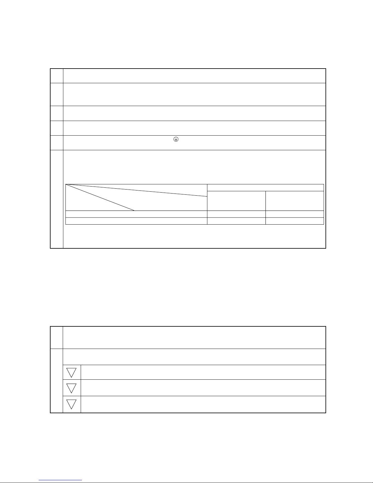
3 TEST RUN
[1] Before Test Run
(1) Check points before test run
1 Neither refrigerant leak nor loose power source/ transmission lines should be found.
2 Confirm that the resistance between the power source terminal block and the ground exceeds 2MΩ by measuring
it with a DC 500 V megger. Do not run if it is lower than 2MΩ.
Note: Never apply a megger to the main board as it will damage the main board.
3 Confirm that the ball valves on gas, liquid, and oil balance sides are fully open.
Note: Be sure to close the cap.
4 Be sure that the crankcase heater has been powered by turning the main power source on at least 12 hours
before starting the test run. The shorter powering time causes compressor trouble.
5 If any of the power supply wires (L1, L2, L3, N, .) are incorrectly connected, it is possible to damage the unit.
Please exercise caution.
6 A transmission booster (RP) is required when the number of connected indoor unit models in a cooling system
exceeds the number of models specified in the chart below.
Note: The maximum number of units that can be controlled is determined by the model of the indoor unit, the
type of remote controller, and their capabilities.
The number of indoor units and the total number of remote controllers is displayed in the parenthesis.
(*1) If even one unit that is higher than 200 exists in the cooling system, the maximum capacity will be “200 or
higher”.
* Please refer to the installation manual for more details.
* Before turning the power of the outdoor unit on, first turn on the transmission booster. (If the outdoor unit are mistakenly
turned on first, turn on the transmission booster, and then reset the outdoor unit power.)
(2) Caution at inverter check
Because the inverter power portion of the electrical part box in the outdoor unit have many parts with high voltage, be
sure to follow the instructions shown below to avoid the risk of electric shock.
During energizing power source, never touch inverter power portion because high voltage (approx. 580 V) is
applied to inverter power portion.
At the time of checking
Shut off the main power, and check the inverter with a tester.
Wait for 10 minutes after shutting off the main power source.
Open the main board mounting panel, and check whether the voltage at both ends of electrolytic
capacitor is 20V or less (if over wait until it is less than 20V)
200 or lower
200 or higher
Remote controller PAR-F 25MA
Prior to Ver. E After Ver. F
16 (32) 20 (40)
16 (32) 16 (32)
(*1)
Capability of the
connected indoor units
Remote controller type
Number of connected indoor units that
can be connected without a RP.
1
2
1
2
3
 Loading...