

Page 1
SPLIT-TYPE, HEAT PUMP AIR CONDITIONERS
OUTDOOR UNIT
PUH-2.5VKA.TH PUH-2.5VKA
1.TH
PUH-3VKA.TH PUH-3VKA
1.TH
PUH-3YKA.TH PUH-3YKA
1.TH
TECHNICAL & SERVICE MANUAL
Outdoor unit
[model names] [Service Ref.]
August 2006
No.OC325
REVISED EDITION-A
PUH-1.6VKA
PUH-1.6VKA.TH
PUH-1.6VKA
PUH-2VKA
PUH-2.5VKA
PUH-2VKA.TH
PUH-2VKA
1
PUH-2.5VKA.TH
PUH-2.5VKA
PUH-3VKA
PUH-3YKA
PUH-4YKSA
PUH-5YKSA PUH-5YKSA
PUH-3VKA.TH
PUH-3VKA
1
PUH-3YKA.TH
PUH-3YKA
1
PUH-4YKSA.TH
PUH-5YKSA
PUH-6YKSA PUH-6YKSA
PUH-6YKSA
1
.TH
.TH
1
.TH
.TH
.TH
.
TH
1
.
TH
.
TH
1
.
TH
Revision:
• PUH-1.6/2/2.5/3VKA1.TH
and PUH-3YKA1.TH,
PUH-5/6YKSA1.TH are
added in REVISED
EDITION-A.
• RoHS PARTS LIST has
been added.
• Some descriptions have
been modified.
• Please void OC325.
Note:
• This manual does not cover indoor units.
• RoHS compliant products have <G> mark on the spec name
plate.
• For servicing of RoHS compliant products, refer to the RoHS
PARTS LIST.
Model name
indication
CONTENTS
1. TECHNICAL CHANGES ·································2
2.
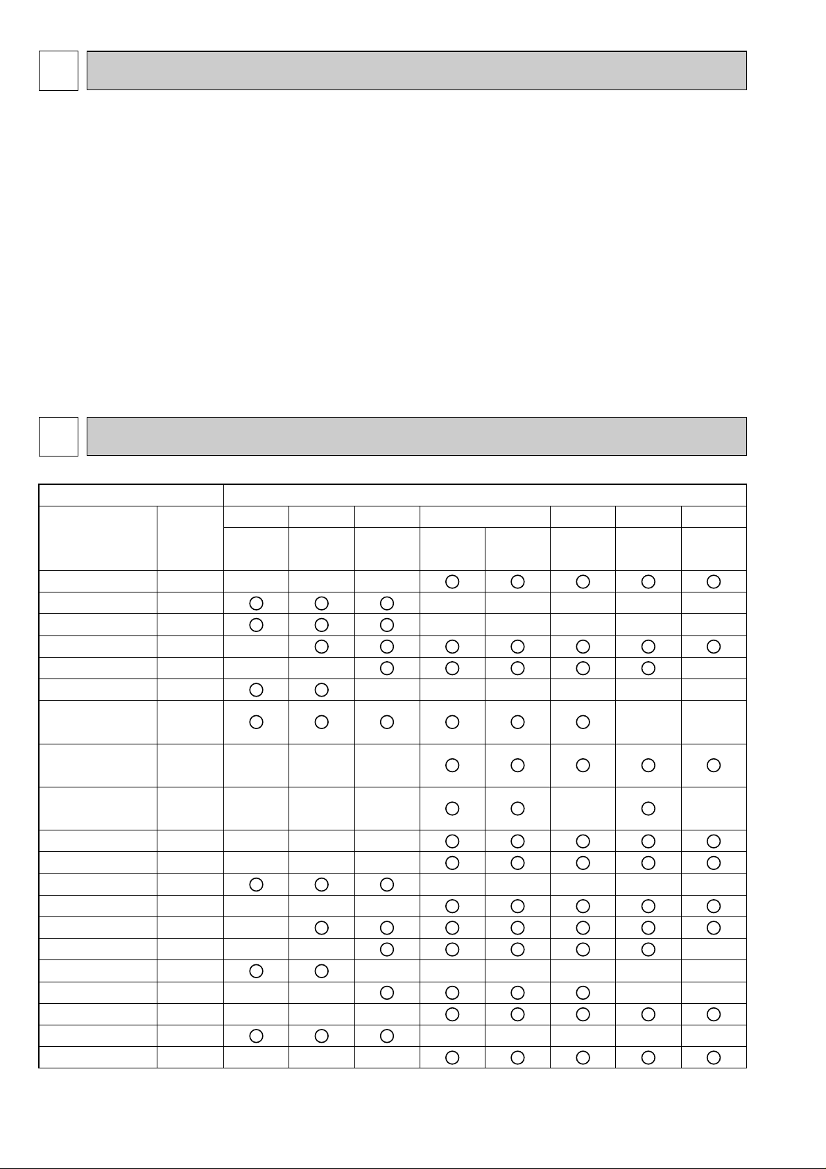
COMBINATION OF INDOOR AND OUTDOOR UNITS
3. PART NAMES AND FUNCTIONS··················3
4. DATA ·······························································4
5. OUTLINES AND DIMENSIONS ······················5
6. WIRING DIAGRAM·········································9
7.
REFRIGERANT SYSTEM DIAGRAM
8. TROUBLE SHOOTING·································15
9. DISASSEMBLY PROCEDURE·····················24
10. PARTS LIST··················································26
11. RoHS PARTS LIST ·······································42
12. OPTIONAL PARTS ·······································54
··············14
···2
Page 2
1 TECHNICAL CHANGES
Indoor unit Outdoor unit
Service
Manual No.
OC096
OC123
OC161
OC135
OC153
OC229
OC130
OC214
OC160
OC387
OC360
OC375
OC400
OC383
OC388
OC392
OC406
OC403
OC168
REVISED
EDITION-A
OC144
REVISED
EDITION-B
PUH-1.6 PUH-2 PUH-2.5 PUH-3 PUH-4 PUH-5 PUH-6
Service Ref.
PLH- • GKH(S)B
PLH- • KKHC
PLH- • KLHC
PCH- • GKH(S)A
1
PEH- • EKH(S)A2.TH
PKH- • GKL(H)
PKH- • FKHA
3
PKH- • FKH(S)A2
PSH- • GJ(H)(S)1
PSH- • GKH(S)
PLH- • AK(H)(S)
PLH- • GLH(S)B
PLH- • KAK(H)
PLH- • AAK(H)
PCH- • GAK(H)
PEH- • EAKH
PKH- • GAKL(H)
PKH- • FAK(H)
PSH- • GAK(H)
PLH- • KAK(H) .UK
PLH- • AAK(H) .UK
—
—
—
—
—
—
—
—
—
—
VKA.TH
—
—
—
—
—
—
—
—
—
—
—
—
—
VKA.TH
—
—
—
—
—
—
—
—
—
—
—
VKA.TH VKA.TH
—
—
—
—
—
—
—
—
—
—
—
—
YKA.TH
YKSA
.TH
—
—
—
—
—
—
—
—
—
—
—
—
—
—
—
YKSA
.TH
—
—
—
—
—
—
—
—
—
—
—
YKSA
.TH
VKA
1.THVKA1.TH VKA1.TH VKA1.TH YKA1.TH
YKSA
1.TH
YKSA1
.TH
PUH-1.6VKA.TH ➔ PUH-1.6VKA1.TH
PUH-2VKA.TH ➔ PUH-2VKA
1
.TH
PUH-2.5VKA.TH ➔ PUH-2.5VKA1.TH
PUH-3VKA.TH ➔ PUH-3VKA1.TH
PUH-3YKA.TH ➔ PUH-3YKA
• 4-WAY VALVE and COIL (21S4) have been changed.
1
.TH
PUH-5YKSA.TH ➔ PUH-5YKSA1.TH
PUH-6YKSA.TH ➔ PUH-6YKSA1.TH
• 4-WAY VALVE and COIL (21S4) have been changed.
• BYPASS VALVE and COIL (21R) have been changed.
2 COMBINATION OF INDOOR AND OUTDOOR UNITS
2
Page 3
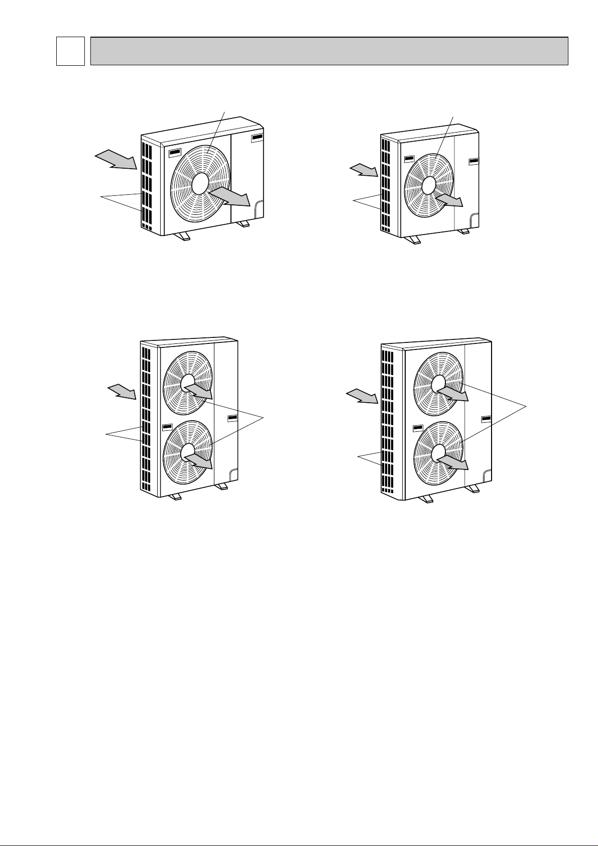
3 PART NAMES AND FUNCTIONS
PUH-1.6VKA.TH
PUH-1.6VKA
1.TH
PUH-2VKA.TH
PUH-2VKA
1.TH
Air intake
Air outlet
(Expels warm air during cooling)
PUH-4YKSA.TH
Air intake
Air outlet
PUH-5YKSA.TH
PUH-5YKSA
1.TH
PUH-6YKSA.TH
PUH-6YKSA
1.TH
Air intake
Air outlet
PUH-2.5VKA.TH
PUH-2.5VKA
1.TH
PUH-3VKA.TH
PUH-3VKA
1.TH
PUH-3YKA.TH
PUH-3YKA
1.TH
Air intake
Air outlet
CHARGELESS SYSTEM
PRE-CHARGED REFRIGERANT IS SUPPLIED FOR MAXIMUM PIPING LENGTH AT SHIPMENT.
The unique refrigerant circuit and a large accumulator always control the optimal refrigerant level regardless of the length
(30m max. and 5m min.) of piping. The additional refrigerant charging work during installation often causes problems.
Heretofore it is completely eliminated. This unique system improves the quality and reliability of the work done. It also helps
to speed up the installation time.
3
Page 4
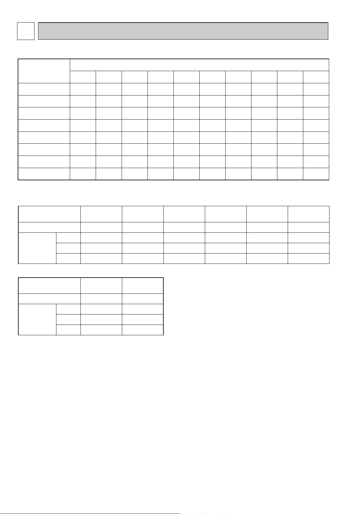
4 DATA
Service Ref.
Refrigerant piping length (one way)
5m 10m 15m 20m 25m 30m 35m 40m 45m 50m
1.5
1.5
2.1
2.5
2.5
3.5
4.7
4.3
1.7
1.7
2.3
2.7
2.7
3.6
4.8
4.4
1.8
1.8
2.4
2.8
2.8
3.8
5.0
4.6
1.9
1.9
2.5
2.9
2.9
3.9
5.1
4.7
2.1
2.1
2.7
3.1
3.1
4.1
5.3
4.9
2.2
2.2
2.8
3.1
3.2
4.2
5.4
5.0
2.3
2.3
2.9
3.1
3.3
4.4
5.6
5.2
2.4
2.4
3.0
3.1
3.4
4.5
5.7
5.3
—
—
3.1
3.1
3.6
4.6
5.9
5.5
—
—
3.3
3.1
3.7
4.8
6.0
5.6
PUH-1.6VKA.TH
PUH-2VKA.TH
PUH-2.5VKA.TH
PUH-3VKA.TH
PUH-4YKSA.TH
PUH-5YKSA.TH
PUH-3YKA.TH
PUH-6YKSA.TH
PUH-1.6VKA
1.TH
PUH-2VKA
1.TH
PUH-2.5VKA
1.TH
PUH-3VKA
1.TH
PUH-5YKSA
1.TH
PUH-3YKA
1.TH
PUH-6YKSA
1.TH
Winding
Resistance
(")
U-V
(R-C)
U-W
(S-C)
W-V
Compressor Model
Outdoor unit
PUH-1.6VKA.TH
PUH-2VKA.TH
PUH-2.5VKA.TH
PUH-3VKA.TH PUH-3YKA.TH
PUH-4YKSA.TH
PUH-1.6VKA
1.TH
PUH-2VKA
1.TH
PUH-2.5VKA1.TH
PUH-3VKA1.TH PUH-3YKA1.TH
RH247VFCT
2.00
4.55
—
NH41VMDT
1.01
2.25
—
NH38VMDT
1.30
2.70
—
NH52VNHT
0.65
1.57
—
NH52YDAT
3.70
3.70
3.70
at 20°C
Winding
Resistance
(")
Compressor Model
Outdoor unit
PUH-5YKSA.TH PUH-6YKSA.TH
PUH-5YKSA1.TH PUH-6YKSA1.TH
ZR68KC-TFD
2.31
2.31
2.31
ZR61KC-TFD
2.53-2.91
2.53-2.91
2.53-2.91
at 25°C
NH56YDAT
3.50
3.50
3.50
T1-T2
T2-T3
T3-T1
4-1. REFILLING REFRIGERANT CHARGE (R-22 : kg)
4-2. COMPRESSOR TECHNICAL DATA
4
Page 5
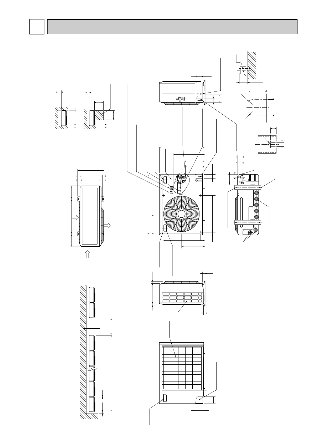
5 OUTLINES AND DIMENSIONS
100 10
1000For 10 units or less
200
Outdoor Unit-Necessary surrounding clearance
(Concentrated installation)
The upper side must be open.
Outdoor Unit-Necessary surrounding clearance
200
10
10
10
Note:Allow adequate
upper clearance
100
500
500
Service space
Front opening
Handle
for moving
138
95
Rear piping hole
23
33
Rear fresh
air intake
Side air intake
7 24(1)295(11-5/8)
Outlet guide
installation hole
302
Air intake
Air intake
Air outlet
870(34-1/4)
185
(7-9/32)
185
(7-9/32)
500(19-11/16)
330(13)
362(14-1/4)
1715
39.5 27.5
Terminal block for indoor and outdoor unit connection
Terminal block for power line
Handle for moving
77
524
339
282
297
444
650 (25-5/8)
40 60524
Service panel
Ground terminal
Refrigerant-pipe flared
connection
[15.88 5/8F
Refrigerant-pipe flared
connection
[9.52 3/8F
Knockout hole
for front piping
(refrigerant,drainage
and wiring)
Knockout hole
for right piping
(refrigerant,drainage
and wiring)
R20
R20
60
120
4553
25 max.
Knockout holes for
power line 2-[27
Standard bolt length
65
Front right piping holes-
detail figures
80
17
42
45
12
R6
104
33
Bottom
piping hole
2-U-shaped
notched
holes
Drain hole
Drain hole
2-12✕23 Oval holes
(standard bolt M10)
Handle for moving
PUH-1.6VKA.TH PUH-1.6VKA1.TH
PUH-2VKA.TH PUH-2VKA1.TH
Unit : mm (inch)
5
Page 6
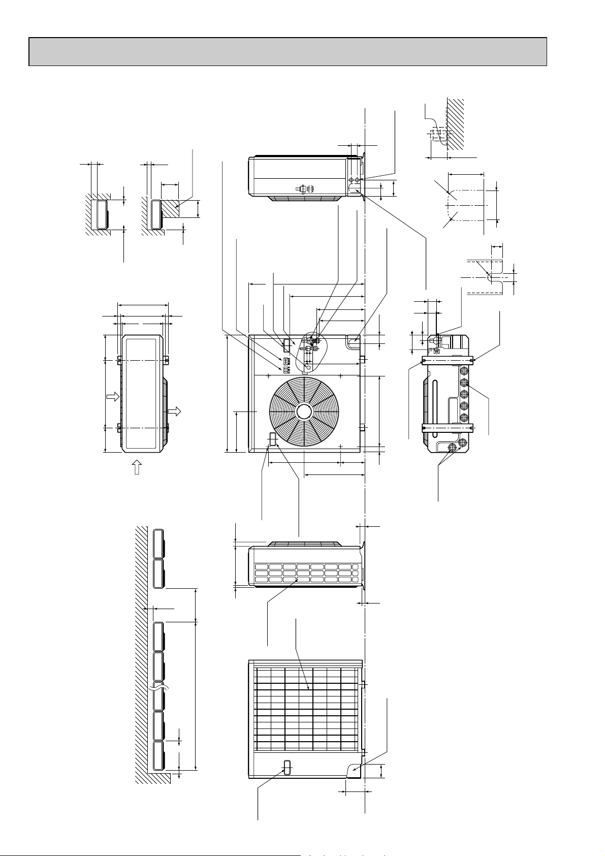
PUH-2.5VKA.TH PUH-2.5VKA1.TH
100 10
1000For 10 units or less
200
Outdoor Unit-Necessary surrounding clearance
(Concentrated installation)
The upper side must be open.
Outdoor Unit-Necessary surrounding clearance
200
10
10
10
Note:Allow adequate
upper clearance
100
500
500
Service space
Front opening
Handle
for moving
138
95
Rear piping hole
23
33
Rear fresh
air intake
Side air intake
7 24(1)295(11-5/8)
Outlet guide
installation hole
302
Air intake
Air intake
Air outlet
870(34-1/4)
185
(7-9/32)
185
(7-9/32)
500(19-11/16)
330(13)
362(14-1/4)
1715
39.5 27.5
Terminal block for indoor and outdoor unit connection
Terminal block for power line
Handle for moving
179 524
441
337
352
403
553
850(33-7/16)
40 60524
Service panel
Ground
terminal
Refrigerant-pipe flared
connection [15.88 5/8F
Refrigerant-pipe flared
connection [9.52 3/8F
Knockout hole
for front piping
(refrigerant,drainage
and wiring)
Knockout hole
for right piping
(refrigerant,drainage
and wiring)
R20
R20
60
120
4553
25 max.
Knockout holes for
power line 2-[27
Standard bolt length
65
Front right piping holes-
detail figures
80
17
42
45
12
R6
104
33
Bottom
piping hole
2-U-shaped
notched
holes
Drain hole
Drain hole
2-12✕23 Oval holes
(standard bolt M10)
Handle for moving
PUH-3VKA.TH PUH-3VKA
PUH-3YKA.TH PUH-3YKA
1.TH
1.TH
Unit : mm (inch)
6
Page 7
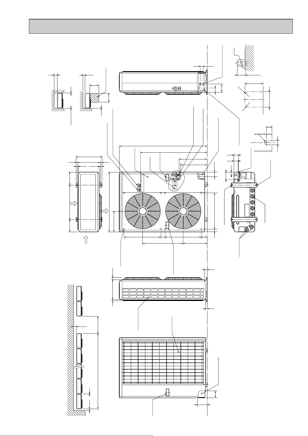
PUH-4YKSA.TH
300
Note:Allow adequate
upper clearance
10
100
500
Service space
500
4553
Unit : mm (inch)
Standard bolt length
Knockout holes for
power line 2-[27
120
60
R20
25 max.
80
65
Outdoor Unit-necessary surrounding clearance
Front opening
10
1715
185
(7-9/32)
Air intake
500(19-11/16)
185
(7-9/32)
10
Terminal block for
indoor and outdoor
unit connection
362(14-1/4)
330(13)
39.5 27.5
870(34-1/4)
Air outlet
Air intake
Terminal block for power line
302
Ground
Service panel
terminal
Handle
for moving
52461
585
Refrigerant-pipe flared
1258(49-1/2)
959
connection [19.05 3/4F
Refrigerant-pipe flared
connection [9.52 3/8F
403
382
83 524
345
Knockout hole
for front piping
(refrigerant,drainage
104
2-12✕23 Oval holes
40 60524
R20
Knockout hole
for right piping
(refrigerant,
drainage and wiring)
and wiring)
57
52
Bottom
39
(standard bolt M10)
piping hole
Drain hole
Front right piping holes-
17
R6
2-U-shaped
notched
holes
Drain hole
detail figures
12
The upper side must be open.
Outdoor Unit-Necessary surrounding clearance
(Concentrated installation)
300
1000For 10 units or less
150 10
Outlet guide
installation hole
7 24(1)295(11-5/8)
Handle for moving
Side air intake
Rear fresh
air intake
33
23
Rear piping hole
95
138
Handle
for moving
7
Page 8
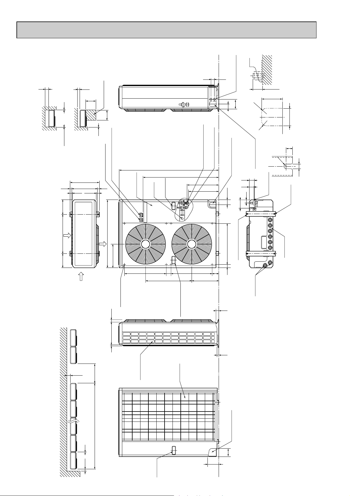
PUH-5YKSA.TH PUH-5YKSA1.TH
150 10
1000For 10 units or less
300
Outdoor Unit-necessary surrounding clearance
(Concentrated installation)
Outdoor Unit-necessary surrounding clearance
The upper side must be open.
Handle
for moving
138
95
Rear piping hole
23
33
Rear fresh
air intake
Side air intake
7 24(1)345(13-9/16)
Outlet guide
installation hole
352
Air intake
Air intake
Air outlet
970(38-3/16)
185
(7-9/32)
185
(7-9/32)
600(23-5/8)
380(14-31/32)
412(16-1/4)
1715
39.5 27.5
Terminal block for
indoor and outdoor
unit connection
Terminal block for power line
300
10
10
10
Note:Allow adequate
upper clearance
100
500
500
Service space
Handle for moving
52461
585
83 524
345
382
403
959
1258(49-1/2)
90 60524
Service panel
Ground
terminal
Handle
for moving
Refrigerant-pipe flared
connection [19.05 3/4F
Refrigerant-pipe flared
connection [9.52 3/8F
Knockout hole
for front piping
(refrigerant,drainage
and wiring)
Knockout hole
for right piping
(refrigerant,
drainage and wiring)
R20
R20
60
120
4553
25 max.
Knockout holes for
power line 2-[27
Standard bolt length
65
Front right piping holes-
detail figures
80
17
52
57
12
R6
104
39
Bottom
piping hole
2-U-shaped
notched
holes
Drain hole
Drain hole
2-12✕23 Oval holes
(standard bolt M10)
Front opening
PUH-6YKSA.TH PUH-6YKSA1.TH
Unit : mm (inch)
8
Page 9
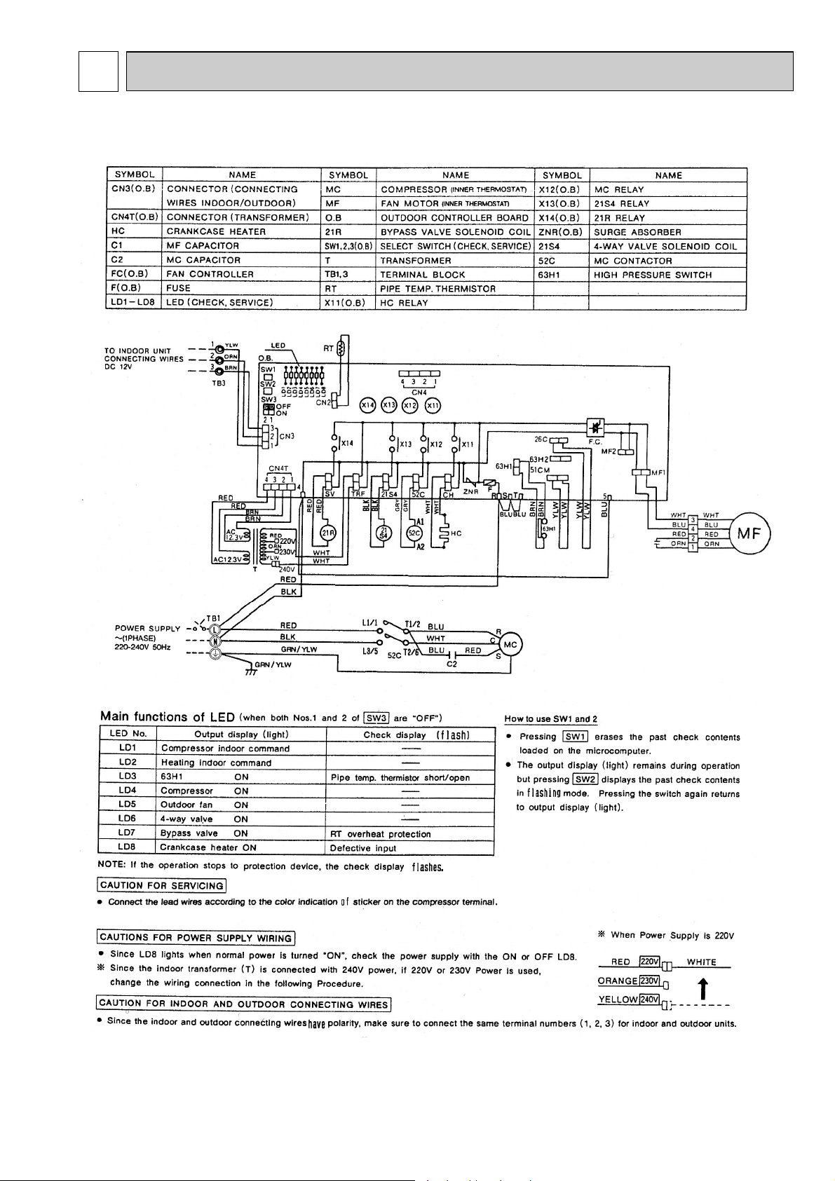
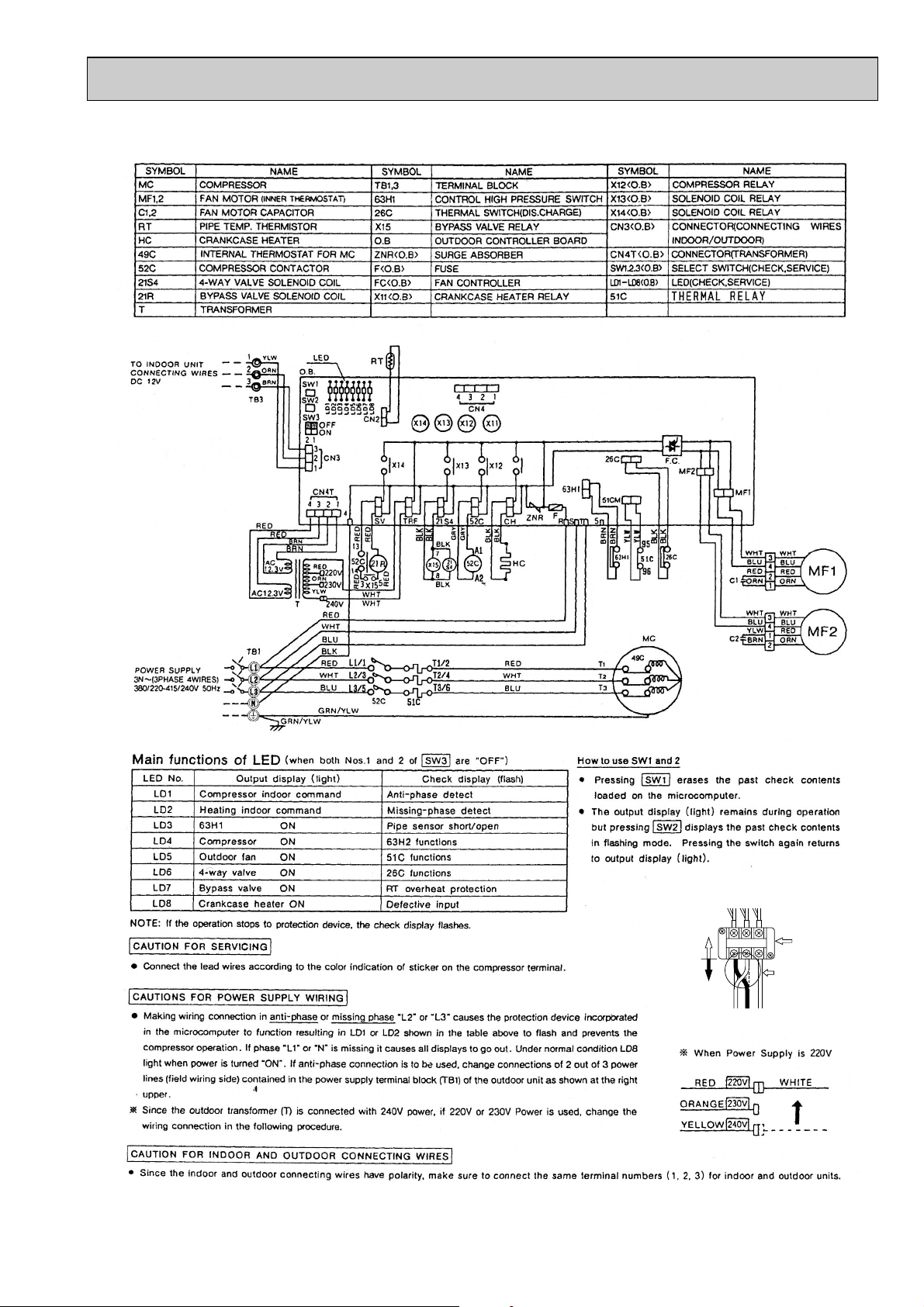
6 WIRING DIAGRAM
PUH-1.6VKA.TH PUH-2VKA.TH PUH-2.5VKA.TH PUH-3VKA.TH
PUH-1.6VKA1.TH PUH-2VKA1.TH PUH-2.5VKA1.TH PUH-3VKA1.TH
(6.3A)
CIRCUIT
BREAKER
C1
9
Page 10
PUH-3YKA.TH PUH-3YKA1.TH
L1L2L3
Power line reconnection procedure
in case of reverse rotation
Unit side
wiring
Outdoor unit
terminal
Field wiring
Change 2 out of
1,
2 and 3.
(This example shows
reconnection of
1
and 2.)
123
Change this side
(6.3A)
CIRCUIT
BREAKER
10
Page 11
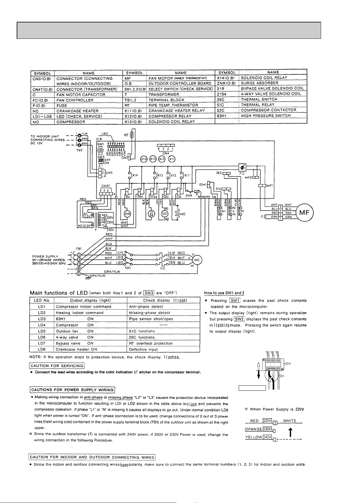
PUH-4YKSA.TH
L1L2L3
Power line reconnection procedure
in case of reverse rotation
Unit side
wiring
Outdoor unit
terminal
Field wiring
Change 2 out of
1,
2 and 3.
(This example shows
reconnection of
1
and 2.)
123
Change this side
(6.3A)
CIRCUIT
BREAKER
11
Page 12
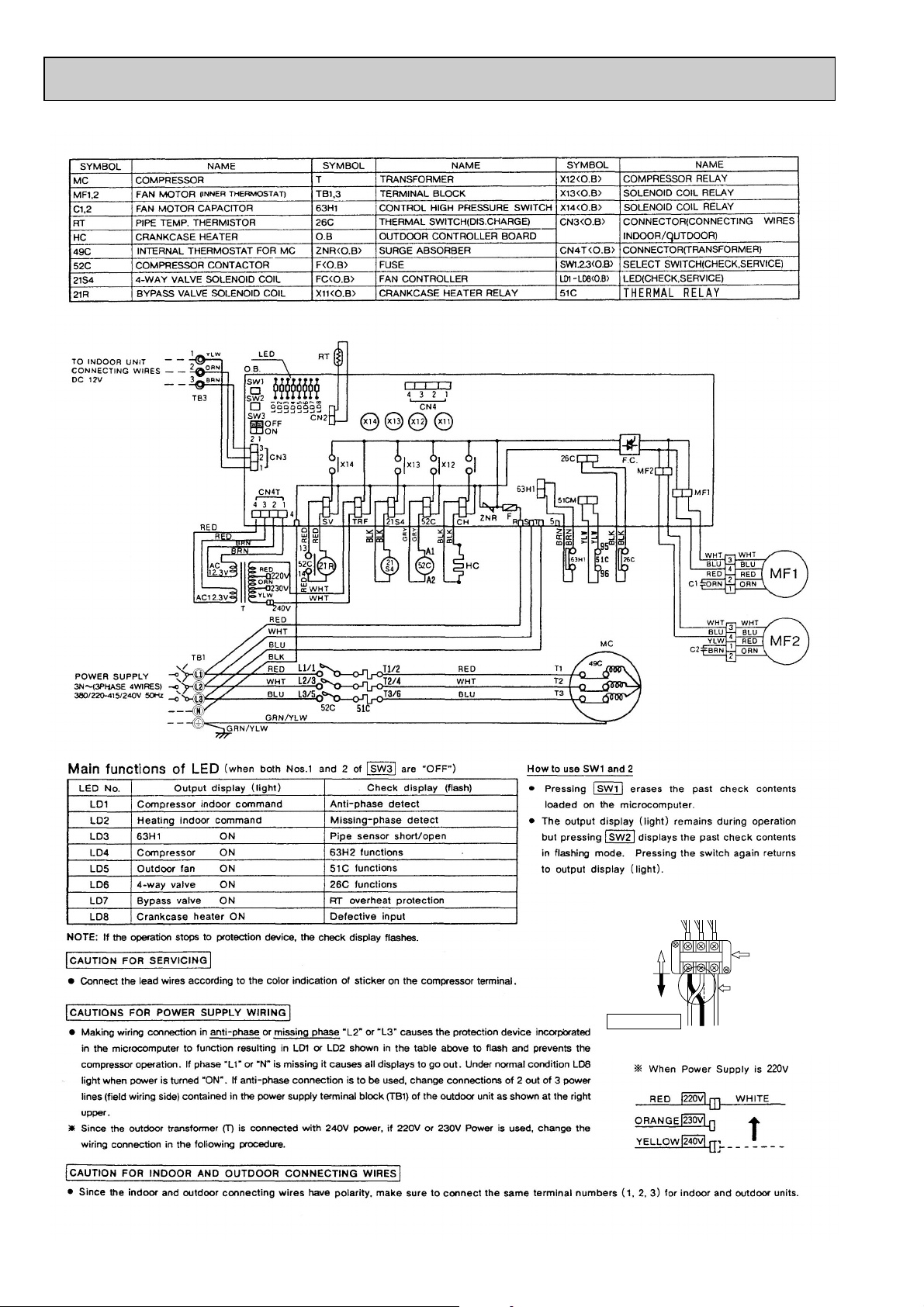
PUH-5YKSA.TH PUH-5YKSA1.TH
L1L2L3
Power line reconnection procedure
in case of reverse rotation
Unit side
wiring
Outdoor unit
terminal
Field wiring
Change 2 out of
1,
2 and 3.
(This example shows
reconnection of
1
and 2.)
123
Change this side
(6.3A)
CIRCUIT
BREAKER
12
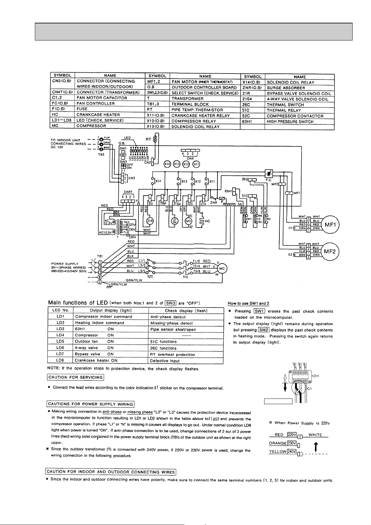
Page 13
PUH-6YKSA.TH PUH-6YKSA1.TH
L1L2L3
Power line reconnection procedure
in case of reverse rotation
Unit side
wiring
Outdoor unit
terminal
Field wiring
Change 2 out of
1,
2 and 3.
(This example shows
reconnection of
1
and 2.)
123
(6.3A)
CIRCUIT
BREAKER
13
Page 14
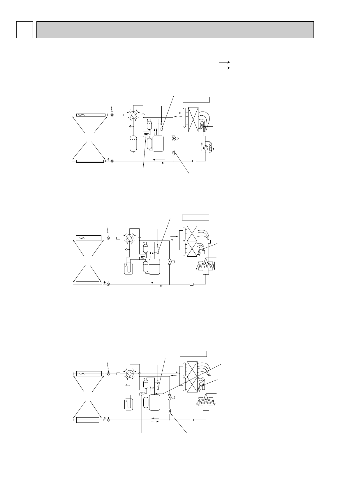
7 REFRIGERANT SYSTEM DIAGRAM
Outdoor unit
Flexible tube
Service
port
Accumulator
Compressor
Refrigerant pipe
(option)
19.05A({3/4")
(with heat insulator)
Refrigerant pipe
(option)
9.52A({3/8")
(with heat insulator)
Ball valve
(with service port)
Strainer
(#50)
Bypass
valve
Restrictor
valve
4-way valve
Oil
separator
Service
port
High pressure
control switch
Outdoor heat exchanger
Thermistor
(RT)
Capillary tube
PUH-5
....
(O.D.4.0✕I.D.2.4-L840)✕2
PUH-6
....
(O.D.4.0✕I.D.2.4-L1200)✕2
Flared
connection
THERMAL
SWITCH
Capillary tube
(O.D.2.5✕I.D.0.6-L1000)
Capillary tube
(O.D.4.0✕I.D.3.0-L200)
Ball valve
(#50)
Strainer
Outdoor unit
Flexible tube
Service
port
(check)
Accumulator
Compressor
Refrigerant pipe
(option)
19.05A({3/4")
(with heat insulator)
Refrigerant pipe
(option)
9.52A({3/8")
(with heat insulator)
Ball valve
(with service port)
Strainer
(#50)
Bypass
valve
Restrictor
valve
4-way valve
Oil separator
Service
port
High pressure
control switch
Outdoor heat exchanger
Outdoor coil
thermistor
(RT)
Capillary tube
(O.D.3.2✕I.D.2.0-L820)✕2
Flared
connection
Capillary tube
(O.D.2.5✕I.D.0.6-L1000)
Ball valve
(#50)
Strainer
Outdoor unit
Flared
connection
Flexible tube
Service
port
Accumulator
Ball valve
(#50)
Strainer
Compressor
Refrigerant pipe
(option)
15.88A({5/8")
(with heat insulator)
Refrigerant pipe
(option)
9.52A({3/8")
(with heat insulator)
Ball valve
(with service port)
Strainer
(#50)
Bypass
valve
Restrictor
valve
4-way valve
Oil separator
Service
port
High pressure
control switch
Outdoor heat exchanger
Outdoor coil
thermistor
(RT)
Capillary tube
PUH-1.6···(O.D.3.2✕I.D.1.8-L600)
PUH-2······(O.D.4.0✕I.D.2.0-L430)
PUH-2.5···(O.D.4.0✕I.D.2.4-L1550)
PUH-3······(O.D.4.0✕I.D.2.4-L1070)
Capillary tube
(O.D.2.5✕I.D.0.6-L1000)
Capillary tube
PUH-1.6 only
(O.D.3.2✕I.D.1.2-L300)
Refrigerant flow in cooling
Refrigerant flow in heating
PUH-1.6VKA.TH PUH-1.6VKA1.TH
PUH-2VKA.TH PUH-2VKA
PUH-2.5VKA.TH PUH-2.5VKA
PUH-3VKA.TH PUH-3VKA
PUH-3YKA.TH PUH-3YKA
1.TH
1.TH
1.TH
1.TH
PUH-4YKSA.TH
PUH-5YKSA.TH PUH-5YKSA1.TH
PUH-6YKSA.TH PUH-6YKSA1.TH
14
Page 15
8
TROUBLESHOOTING
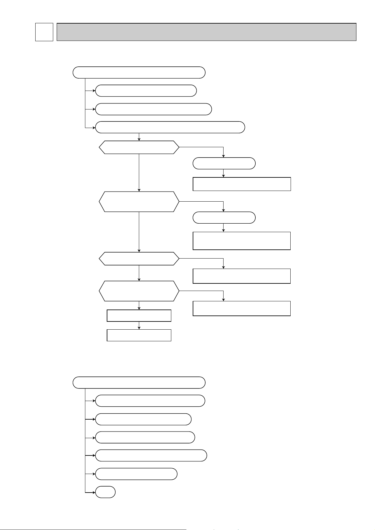
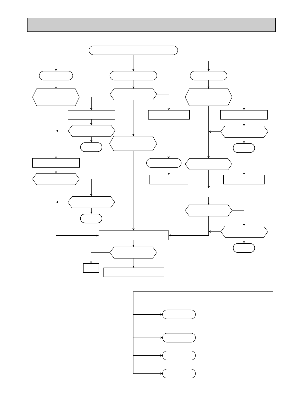
8-1. TROUBLESHOOTING
The unit does not operate at all or it does not keep operating.
No display appears on the remote controller.
The error code is displayed on the remote controller.
“CENTRALLY-CONTROLLED” is displayed on the remote controller.
Is the remote operation available by
the adapter for connecting the timer?
No
Does the remote controller for
central control allow the unit to be
operated or stopped with the
local remote controller?
No
Is the address setting correct?
Yes
Is the setting of multi operation
switch (SW6) correct?
Yes
Yes
No
No
······································· Refer to page 16
··························· Refer to page 17
The operation is normal.
Set the remote operation switch to the local
remote controller side.
The operation is normal.
Set the centralized remote controller to allow
the unit to be operated or stopped with the
local remote controller.
Set the address again, turn the power supply
off and turn it on again.
Yes
Replace the remote controller.
Check if the remote controller
operates normally.
The unit operates, but there are the following problems.
The room cannot be cooled or heated sufficiently. ································· Refer to page 20
The room is cooled or heated excessively.
The operating sound or the vibration is big.
The air from the unit smells strange.
Water leakage, dew dropping or splashing occurs.
The parts are removed or deformed.
Set the SW6 again, turn the power supply off
and turn it on again.
············································ Refer to page 20
········································· Refer to page 20
······························· Refer to page 21
······················································· Refer to page 21
·········································································································· Refer to page 21
Others
15
Page 16
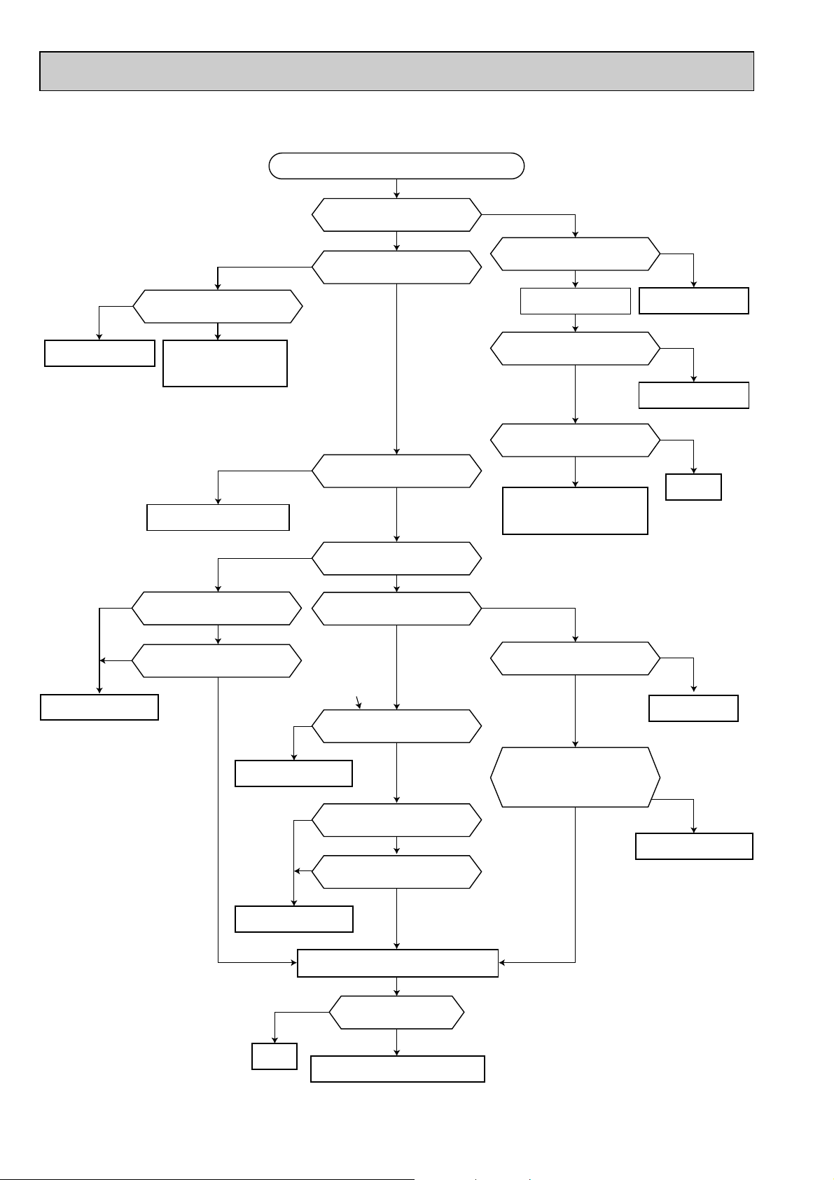
No display appears on the remote controller.
No
Is the voltage of the indoor/outdoor
unit connecting terminal block 240V?
Power supply system
is abnormal.
No
Is the connector CN40 connected
properly?
No
Is the transmission wire of remote
controller connected properly?
Connection is defective.
Yes
The power supply wire
and the indoor/outdoor
unit connecting wire are
in reverse connection.
Replace the remote controller.
Yes or Model without CN40
Yes
Install the CN40 in only
one indoor unit.
Connection is defective.
Is the breaker for the indoor unit
turned on?
Yes
No
Is the voltage of the indoor power
supply terminal block 240V?
Yes
Yes
Is the voltage of the remote
controller terminal block DC12V?
No
Yes
Does the LED1 (DC12V) on the
indoor controller board light?
No
Does the LED2 (DC5V) on the
indoor controller board light?
Yes
When the two or
three indoor units
are connected to
an outdoor unit.
Yes
Is the connector CN40 installed in
the two or more indoor units?
No
or
Model without CN40
Yes
Is the indoor/outdoor unit connecting
wire short-circuited?
No
Yes
Is the transmission wire of remote
controller short-circuited?
No
No
Is the breaker capacity appropriate?
Yes
Turn the breaker on and
operate the unit again.
Is the breaker turned off automatically?
No
Does the unit operate normally?
No
If any error code is displayed
on the remote controller,
follow the diagnosis of the
displayed error code.
No
Is the 6.3A fuse on the indoor
controller board melted?
No
CND, CNT, CN4T
Are the wire and the connector
connected properly?
Does the LED2 (DC5V) on the
indoor controller board light?
Yes
No
Replace the breaker
Yes
Electric leakage or
overcurrent occurs.
Yes
Finished
Yes
Replace the fuse.
No
Connection is defective.
No
Normal
Turn off the power supply and turn it on again
to operate the unit in COOL or HEAT mode.
No display appears on the
remote controller.
Yes
Check the indoor controller board
16
Page 17
The error code is displayed on the remote controller.
Communication error Sensor is abnormal Communication error
E0 is displayed.
Turn the breaker off and
turn it on again.
Is it possible to operate
the unit?
No
Use the remote controller as it is. Use the remote controller as it is.
Yes
Is E0 displayed frequently?
Replace the remote controller.
Is E0 displayed again?
Yes
No
Yes
No
Finished
No
Does the unit operate
normally?
Yes
Finished
P1, P2 or P4 error is displayed.
Is the connector of
the abnormal sensor
connected properly?
Yes
Connection is defective.
Check the resistance of
the abnormal sensor.
Is there a short or open
circuit in the sensor?
No
Sensor is abnormal.
Replace the abnormal
sensor.
No
Yes
P3 or E4 is displayed.
Turn the breaker off and
turn it on again.
Is it possible to operate
the unit?
No
Yes
Is the transmission wire
of remote controller
connected properly?
Yes
Connection is defective.
Replace the remote controller.
Is P3 or E4
displayed again?
Yes
Yes
Is P3 or E4
displayed frequently?
No
Finished
No
No
Normal
Turn off the power supply and turn it on again
to operate the unit in COOL or HEAT mode.
No
The error code is displayed
on the remote controller.
Yes
Check the indoor controller board
Abnormality of drain pump
Freezing protection
Overheating protection
System error
P5 is displayed.
P6 is displayed.
P7 is displayed.
No
··································· Refer to page 18
··································· Refer to page 18
··································· Refer to page 18
Does the unit operate
normally?
Yes
Finished
17
P8 is displayed.
··································· Refer to page 19
Page 18

Abnormality of drain pump Freezing protection and Overheating protection
P5 is displayed.
Operate the unit again in
the COOL mode.
Does the drain pump operate?
Yes
Is the connector of the drain pump
connected properly?
Connection is defective.
Is the breaker turned off automatically?
Yes
Improve the drainage
condition.
Is the connector of the drain sensor
connected properly?
Yes
Connection is defective.
No
No
No
No
Yes
Drain sensor is defective.
P6 is displayed.
Is the filter clogged?
No
Operate the unit again.
Does the indoor unit fan rotate?
No
Are there any obstacles at the
air inlet/outlet?
No
Yes
Clean the filter.
Yes
Yes
Remove the obstacles.
Check the resistance of the drain
sensor heater.
Is there a short or open circuit in
the sensor?
Is the drain sensor connecting
properly?
No
Drain sensor is defective.
Yes
Connecting it correctly.
Yes
Replace it.
No
Turn off the power supply and turn it on again
to operate the unit in COOL or HEAT mode.
No
No display appears on the
remote controller.
Yes
Normal
Check the indoor controller board
P7 is displayed.
Is the address setting correct?
Yes
No
Set the address again, turn
the power supply off and
turn it on again.
18
Page 19

No
Is the breaker for the outdoor unit
turned on?
Turn the breaker on.
Yes
Does the LED (LD2) displayed the
different voltage light?
The power supply wire
and the indoor/outdoor
unit connecting wire are
in reverse connection.
Yes
Replace the fuse.
Yes
No
Is the 6.3A fuse on the outdoor
controller board melted?
No
P8 is displayed.
Yes
Are there the LED on the outdoor
controller board?
No
Is the breaker for the outdoor unit
turned on?
No
Is the breaker capacity appropriate?
Yes
Turn the breaker on.
Operate the unit again.
Yes
No
Replace the breaker
No
Connection is defective.
Yes
TROUBLESHOOTING
ACCORDING TO
CHECK CODE
Refer to 8-2.
Are the wire and the connector
connected properly?
Yes
Does the LED indicator blink?
No
Is the breaker turned off automatically?
No
Does the unit operate normally?
No
Is the voltage of the terminal block
for transmission wire of outdoor unit
DC12V?
No
Is the voltage of the terminal block
for transmission wire of indoor unit
DC12V?
No
Is the connector on the outdoor
controller board connected properly?
Yes
Check the resistance of the pipe
temperature thermistor.
Is there a short or open circuit in
the thermistor?
No
Turn off the power supply and turn it on again
to operate the unit in COOL or HEAT mode.
Yes
Electric leakage or
over current occurs.
Yes
Yes
Yes
No
Yes
Finished
Is the connector on the outdoor
controller board connected properly?
No
Connection is defective.
Is the indoor control wire
connected properly?
No
Connection is defective.
Connection is defective.
Replace the pipe
temperature thermistor.
Yes
Yes
Normal
No
The error code is displayed
on the remote controller.
Yes
Check the outdoor controller board.
19
Page 20

The room cannot be cooled
or heated sufficiently.
The room is cooled or
heated excessively.
The operating sound or the vibration is big.
The air from the unit smells strange.
Is the filter clogged?
No
Is the temperature
set correctly?
Yes
Is the indoor or outdoor
unit free from any objects
that block its airflow?
Yes
Is the window left open?
No
Is the selected model
appropriate to the room
size?
Yes
Yes
Clean the filter.
No
Set it correctly.
No
Short cycle occurs.
Remove the
obstacles.
Yes
Close it.
No
The appropriate
model is not
selected.
Is the temperature
set correctly?
Yes
Does the thermostat
stop working when the set
temperature has been
achieved?
Is the room temperature
thermistor installed properly?
Check the resistance of the
room temperature thermistor.
Yes
Yes
Normal
The room temperature
thermistor is defective.
No
Set it correctly.
No
No
Install it correctly.
Abnormal (open or short)
Replace it.
Check the conditions of
filter and heat exchanger.
Improve the conditions.
Normal
Turn off the power supply and turn it on again
to operate the unit in cooling or heating mode.
No
The error code is displayed
on the remote controller.
Yes
Check the indoor controller board
20
Page 21

8-2. TROUBLESHOOTING ACCORDING TO CHECK CODE
The parts are removed or deformed.
Others
Water leakage, dew dropping or splashing occurs.
Check the condition.
Replace the pipes
or insulation with
new one.
Clean the filter.
Repair the defective part.
Correct the removed
parts or replace the
deformed parts with
new one.
Is the humidity in
the room high?
Yes
No
Is the connection of drain
pipe defective?
Is the insulation of drain
pipe defective?
Is the insulation of
refrigerant pipe defective?
Yes
No
Yes
No
Yes
No
Check the condition.
Blinking
LED
LD1 Reversed phase Phases L1, L2, and L3are con-
LD2
Diagnosis of malfunction Cause Check point
Check the power supply connection.
nected improperly.
Open phase ● Phase L2is open.
● Contact of protector, such as
● Check the power supply.
● Check each protector.
thermal switch, opened when
power was turned on.
LD3 Outdoor coil thermistor is
abnormal. (Open circuit or short
circuit)
LD4 High pressure switch (63H2)
function
LD5 Thermal relay (51C) function ● 51C was connected incor-
LD6 Thermal switch (26C) function ● 26C was connected incor-
LD7 Over heat protection ● The thermistor is broken.
LD8 Input circuit of outdoor con-
troller board is abnormal.
● Outdoor coil thermistor is
broken.
● Thermistor was connected
incorrectly.
● 62H2 was badly connected.
● 63H2 was working.
● Measure the resistance of the thermistor.
● Check the thermistor. If normal, replace the
outdoor controller board.
● Check 63H2 and the outdoor fan motor.
● Check if refrigerant supply is low.
● Check if air cycle is short-cycled.
● Check 51C, the compressor, and power supply.
rectly.
● 51C was working.
● Check 26C.
rectly.
● 26C was working.
● Check if refrigerant supply is low.
● Check if the capillary tube is clogged.
● Measure the resistance of the thermistor.
● Coil temperature is over
67°C.
● Check the outdoor fan motor.
● Check if air cycle is short-cycled.
● Pulse input is abnormal. ● Replace the outdoor controller board.
21
Page 22

Parts name
Check points
Disconnect the connector then measure the resistance using a tester.
(Ambient temperature 10:~30:)
OUTDOOR COIL
THERMISTOR
(RT)
Normal
4.3k"~9.6k"
Abnormal
Open or short circuit
Measure the resistance between the terminals using a tester.CRANKCASE
HEATER (HC)
Normal Abnormal
Open or short circuit
Measure the resistance between the terminals using a tester.
(
Ambient
temperature 20C°)
FAN MOTOR
(MF, MF1, MF2)
Motor lead wire
Abnormal
Open or short
circuit
Open or
short circuit
Open or
short circuit
White — Blue
Blue — Red
Red
Blue
White
Orange
Protector
OPEN :145i8:
CLOSE :90i15:
Protector
1.6, 2, 2.5, 3 4 5 6
Normal
68.8"
88.4"
94.1"
79.4"
143.0"
195.0"
117.4"
125.3"
Normal
Terminals
PUH-1.6V PUH-2V PUH-2.5V PUH-3V PUH-3Y PUH-4Y
Abnormal
RH247VFCT NH38VMDT NH41VMDT NH52VNHT NH52YDAT NH56YDAT
U-V(R-C)
U-W(S-C)
W-V
2.00"
4.55"
—
1.30"
2.70"
—
1.01"
2.25"
—
0.65"
1.57"
—
3.70"
3.70"
3.70"
3.50"
3.50"
3.50"
Winding resistance(")
Measure the resistance between the terminals using a tester.
at 20:
Normal
Terminals
PUH-5Y PUH-6Y
Abnormal
ZR61KC-TFD ZR68KC-TFD
T1-T2
T2-T3
T3-T1
2.53-2.91"
2.53-2.91"
2.53-2.91"
2.31"
2.31"
2.31"
at 25:
1.6 2, 2.5, 3, 4, 5, 6
1920"I7% 1516"I7%
U
V
W
49C
49C
49C
T3
T2
T1
COMPRESSOR
(MC)
[PUH-1.6-4]
[PUH-5.6]
8-3. HOW TO CHECK THE PARTS
PUH-1.6VKA.TH PUH-2.5VKA.TH PUH-3YKA.TH PUH-5YKSA.TH
PUH-1.6VKA
1.TH PUH-2.5VKA1.TH PUH-3YKA1.TH PUH-5YKSA1.TH
PUH-2VKA.TH PUH-3VKA.TH PUH-4YKSA.TH PUH-6YKSA.TH
PUH-2VKA
1.TH PUH-3VKA1.TH PUH-6YKSA1.TH
22
Page 23

8-4. OUTDOOR UNIT SERVICE FUNCTIONS (OUTDOOR CONTROLLER BOARD)
(1) Compulsory defrosting
1When all of the following conditions are satisfied, pressing SW2 starts the compulsory defrosting.
● During HEAT mode
● The compressor is ON.
● The outdoor coil temperature is being displayed by LED. (Outdoor controller board dip switch SW3-1 : OFF, SW3-2 :
ON)
● The outdoor coil thermistor reads 8°C or below.
2The operation state and the termination conditions of the compulsory defrosting are the same as those of the normal
defrosting. As an exception, the defrost interval after the defrosting completion is 50 minutes.
(2) Fixed fan-output
While the compressor is operating (except during defrosting) and the fan output step is indicated by LED, pressing SW2
fixes the fan output. The fixed fan-output can be released when any of the following conditions are satisfied.
1SW2 is pressed again.
2SW3 setting is changed.
3The compressor stops.
4Defrosting operation starts.
(3) Function of switches on the outdoor controller board
SW1: Clears the check code memory (push-button switch)
SW2: Switches the output state indication and the check code display (push-button switch)
SW3-1,2: Switches the output state indication items (dip switch)
(4) 100% fan output
Fan output is fixed to 100% by shorting the connector CN22. However, the fan stops during compressor OFF or defrosting.
Open-circuit of CN22 restarts the normal fan control.
(5) Time shortening
Short circuit of the connector CN21 shortens the time as follows
1Fan control period: 30 seconds → 3 seconds
2Three-minutes time delay function : 3 minutes → 3 seconds
3Max. time of defrosting : 15 minutes → 15 seconds
4Defrost interval : 30 ~ 120 minutes → 3 ~ 12 seconds
5Compressor ON/OFF time for bypass valve ON/OFF : 30 minutes → 3 seconds
6Compressor ON time to start other functions : x minutes → x seconds
7Crankcase heater operation : 1 hour → 6 seconds
(6) Crankcase heater control
1With jumper wire J3
The crankcase heater is ON the moment the power is turned ON until the compressor starts, and then turns ON again
one hour after the compressor stops.
2Without jumper wire J3
The crankcase heater is ON the moment the power is turned ON until the compressor starts, and repeats 1-hour ON
again and 1-hour OFF, after the compressor stops.
23
Page 24

9 DISASSEMBLY PROCEDURE
Service Ref. : PUH-2.5,3VKA.TH PUH-2.5,3VKA1.TH PUH-3YKA.TH PUH-3YKA1.TH
OPERATING PROCEDURE PHOTOS
1. Removing the electrical parts
(1)
Remove the 5 screws and the top panel. (3 screws in
front and 2 screws in rear
(2)
Remove the screw of the cover panel. To remove the
cover panel, pull it toward you and unhook the catches from the side panel.
(3)
Remove the screw of the service panel. To remove the
service panel, pull it down toward you and unhook the
catches on the both sides.
)
Photo 1
Screws
Front panel
Photo 2
Outdoor controller
board
Top panel
Service panel
Panel cover
Transformer Capacitor
Contactor
2. Removing the fan motor
(1)
Remove the 3 screws of the front panel. Open the
front panel to a 45-degree angle. Then lift it and
unhook the 3 catches to remove.
(2)
Remove the propeller nut and the propeller.
(3)
Remove the 3 screws and the fan motor.
Disconnect the lead connectors.
Photo 3
Propeller
Motor support
Overcurrent
relay
Terminal blockScrews
Separator support plate
High-pressure control
switch
Lead
connectors
Valve bed
24
Propeller nut Crankcase heater
Page 25

OPERATING PROCEDURE PHOTOS
3. Removing the heat exchanger and the compressor
(1)
Remove the rear panel (2 screws in front, 1 screw on
the side, 3 screws in the rear). Remove the valve bed,
and open the rear panel to the rear to remove.
NOTE :
All panels are fixed by catches, and must be removed by
shifting up and down.
(2)
Remove the 4 screws of the right side panel and
remove the right side panel.
(3)
Remove the 3 screws of the rear guard and remove
the rear guard.
(4)
Remove the 4 screws of the separator support plate
and remove the separator support plate.
(5)
Remove the 2 screws of the motor support and
remove the motor support.
(6)
Remove the 5 screws of the valve bed.
The valve bed is fixed by the catches on the right and
left sides.
Lift it to remove.
(7)
Remove the electrical parts box.
Disconnect the connectors from the high pressure
switch, crankcase heater, shell thermo, and fan motor
lead.
(8)
Remove the 2 screws of the separator and remove the
separator.
(9)
Remove the 2 screws of the heat exchanger and
remove the heat exchanger.
Detach the welded point of pipe.
)
(
Remove the 3 nuts of the compressor and remove the
10
compressor.
Detach the welded points of the compressor suction
pipe and discharge pipe.
Photo 4
Screws
Screws
Photo 5
Heat exchanger
Accumulator
25
Photo 6
Charge plug
Ball valve
Compressor
Page 26

10 PARTS LIST (non-RoHS compliant)
E02 214 297
—
E07 001 249
E07 001 009
E07 001 232
E07 001 521
E07 001 290
E07 003 290
—
E07 001 245
E07 001 006
E07 001 522
—
E07 001 523
1
2
3
4
5
6
7
8
9
10
11
12
13
Part No. SpecificationNo.
Wiring
Diagram
Symbol
Recommended
Q,ty
Price
Unit
Amount
Part Name
Q,ty/set
PUH-1.6 PUH-2
Remarks
(Drawing No.)
TOP PANEL
SCREW
LEFT SIDE PANEL
HANDLE
FRONT PANEL
FAN GUARD
BASE
BASE
MOTOR SUPPORT
SERVICE PANEL
PANEL COVER
REAR PANEL
LABEL
REAR GUARD
(Z004M203H10)
(BG00N264G06)
(JG79C180H02)
13PCS/SET
(5✕10)
VKA.TH / VKA1.TH
1
13
1
3
1
1
1
1
1
1
1
1
1
1
13
1
3
1
1
1
1
1
1
1
1
1
STRUCTURAL PARTS
PUH-1.6VKA.TH PUH-1.6VKA1.TH
PUH-2VKA.TH PUH-2VKA1.TH
1
13
12
114
SCREW
2
3
4
5
6
78 9 10
26
Page 27

PARTS LIST (non-RoHS compliant)
E02 214 297
—
E02 214 249
E07 003 232
E07 001 009
E02 527 521
E07 003 290
—
E07 003 245
E07 001 006
E07 003 522
—
E07 003 523
1
2
3
4
5
6
7
8
9
10
11
12
13
Q,ty/set
PUH- • KA.TH/KA1.TH
2.5/3V,3Y
(5✕10)
(Z004M203H10)
(SU02Y704G04)
(JG79C180H02)
Part No. SpecificationNo.
Wiring
Diagram
Symbol
Recommended
Q,ty
Price
Unit
Amount
Part Name
Remarks
(Drawing No.)
TOP PANEL
SCREW
LEFT SIDE PANEL
FRONT PANEL
HANDLE
FAN GUARD
BASE
MOTOR SUPPORT
SERVICE PANEL
PANEL COVER
REAR PANEL
LABEL
REAR GUARD
1
13
1
1
3
1
1
1
1
1
1
1
1
13PCS/SET
STRUCTURAL PARTS
PUH-2.5VKA.TH PUH-2.5VKA
PUH-3VKA.TH PUH-3VKA
PUH-3YKA.TH PUH-3YKA
1.TH
1.TH
1.TH
SCREW
13
12
1
2
3
11
4
5
5
6
78 9
10
27
Page 28

PARTS LIST (non-RoHS compliant)
STRUCTURAL PARTS
PUH-4YKSA.TH
SCREW
13
1011 912
87
1
6
2
3
5
43
Part No.
1
E07 005 232
2
E02 527 521
3
E07 001 009
4
E07 005 290
5
E07 001 006
6
E07 005 522
7
E07 005 245
8
9
E07 005 523
10
E02 214 297
11
12
13
E07 005 249
—
—
—
Part Name
FRONT PANEL
FAN GUARD
HANDLE
BASE
PANEL COVER
REAR PANEL
SERVICE PANEL
LABEL
REAR GUARD
TOP PANEL
MOTOR SUPPORT
SCREW
LEFT SIDE PANEL
SpecificationNo.
(5✕10)
Q,ty/set
PUH-4YKSA.TH
1
2
3
1
1
1
1
1
1
1
1
13
1
28
Remarks
(Drawing No.)
(JG79C180H02)
(BG00N264G08)
13PCS/SET
(Z004M203H10)
Wiring
Diagram
Symbol
Recom-
mended
Q,ty
Unit
Price
Amount
Page 29

PARTS LIST (non-RoHS compliant)
STRUCTURAL PARTS
PUH-5YKSA.TH PUH-5YKSA1.TH
PUH-6YKSA.TH PUH-6YKSA1.TH
SCREW
13
1011 912
87
1
6
2
3
5
43
Part No.
1
E07 016 232
2
E02 527 521
3
E07 001 009
4
E07 016 290
5
E07 016 006
6
E07 016 522
7
E07 016 245
8
9
E07 016 523
10
E07 016 297
11
12
13
E07 016 249
—
—
—
Part Name
FRONT PANEL
FAN GUARD
HANDLE
BASE
PANEL COVER
REAR PANEL
SERVICE PANEL
LABEL
REAR GUARD
TOP PANEL
MOTOR SUPPORT
SCREW
LEFT SIDE PANEL
SpecificationNo.
(5✕10)
29
Q,ty/set
PUH-
5,6YKSA.TH
5,6YKSA
1.TH
1
2
3
1
1
1
1
1
1
1
1
13
1
Remarks
(Drawing No.)
(JG79C180H02)
(BG00N264G08)
13PCS/SET
(Z004M203H10)
Wiring
Diagram
Symbol
Recommended
Q,ty
Unit
Price
Amount
Page 30

PARTS LIST (non-RoHS compliant)
FUNCTIONAL PARTS
PUH-1.6VKA.TH
PUH-1.6VKA
1
1.TH
FUSE
21
2022
THERMISTOR
192328 2427 252629
18
2
NUT
3
17
16
15
14
13
12
11
10
9
8
5
4
6
7
30
Page 31

Part No. Part Name SpecificationNo.
Wiring
Diagram
Symbol
Recom-
mended
Q,ty
Price
Unit
Amount
Remarks
PUH-1.6
VKA.TH VKA1.TH
E07 011 301
E07 001 501
E07 070 508
E07 011 374
E07 006 375
E07 177 240
E07 001 900
E02 010 662
E07 001 661
E07 011 932
E07 001 641
E07 177 934
E07 011 492
E07 177 937
E02 096 642
E07 177 933
E07 011 490
E07 275 490
E07 011 387
E07 275 387
E07 011 307
E07 011 388
E07 012 299
E07 011 646
E07 001 340
E07 011 339
E07 278 339
E02 063 351
E02 816 353
E07 011 451
E07 275 451
E07 006 382
E07 011 630
E07 177 936
1
2
3
4
5
6
7
8
9
10
11
12
13
14
15
16
17
18
19
20
21
22
23
24
25
26
27
28
29
30
PK6V85-UA
M8
3P(1,2,3)
3P(L,N,;)
240V 30W
RH247VFCT
3/8˝
5/8˝
{3.2✕{1.8✕600mm
OFF : 2.55 MPa, ON : 2.1 MPa
2.5+ 440V AC
35+ 440V AC
250V 6.3A
{3.2✕{1.2✕300mm
1
1
1
1
1
1
1
1
1
1
2
1
1
1
1
1
1
1
1
1
1
1
1
1
1
1
1
1
1
1
1
1
1
1
1
1
1
1
1
1
2
1
1
1
1
1
1
1
1
1
1
1
1
1
1
1
1
1
1
1
MF
TB3
TB1
HC
MC
21S4
21S4
RT
21R
63H1
52C
T
T
C1
C2
O.B
O.B
F(O.B)
OUTDOOR FAN MOTOR
PROPELLER FAN
NUT
TERMINAL BLOCK
TERMINAL BLOCK
CRANKCASE HEATER
COMPRESSOR
BALL V AL VE (LIQ)
BALL V AL VE (GAS)
ACCUMULA T OR
CHARGE PLUG
STRAINER
BYP ASS V AL VE
CAPILLARY TUBE
RESTRICTOR V AL VE
STRAINER
4-WAY VALVE SOLENOID COIL
4-WAY VALVE SOLENOID COIL
4-WAY VALVE
4-WAY VALVE
PIPE TEMPERA TURE THERMISTOR
BYPASS VALVE SOLENOID COIL
OIL SEPARATOR
HIGH PRESSURE SWITCH
COMPRESSOR CONTACTOR
TRANSFORMER
TRANSFORMER
FAN MOTOR CAPACITOR
COMPRESSOR CAPACITOR
OUTDOOR CONTROLLER BOARD
OUTDOOR CONTROLLER BOARD
FUSE
HEAT EXCHANGER
CAPILLARY TUBE
Q,ty/set
PARTS LIST (non-RoHS compliant)
Part number that is circled is not shown in the figures.
31
Page 32

PARTS LIST (non-RoHS compliant)
FUNCTIONAL PARTS
PUH-2VKA.TH
PUH-2VKA1.TH
NUT
29
FUSE
28
20
THERMISTOR
192223 212427 2526
1
18
17
16
15
2
14
13
12
3
11
456 7 8 9
10
32
Page 33

PARTS LIST (non-RoHS compliant)
Part No. Part Name SpecificationNo.
1
E07 011 301
2
E07 001 501
3
E07 070 508
4
E07 011 374
5
E07 006 375
6
E07 011 492
7
E02 007 900
8
E07 011 240
9
E02 010 662
10
E07 001 661
11
E07 001 641
12
E07 011 934
13
E07 011 932
14
E07 011 933
15
E02 096 642
16
E07 011 936
E07 011 490
17
E07 275 490
E07 011 387
18
E07 275 387
19
E07 011 307
20
E07 011 388
21
E07 011 299
22
E07 011 646
23
E07 012 340
E07 011 339
24
E07 278 339
25
E02 063 351
26
E02 946 353
E07 011 451
27
E07 275 451
28
E07 006 382
29
E07 011 630
OUTDOOR FAN MOTOR
PROPELLER FAN
NUT
TERMINAL BLOCK
TERMINAL BLOCK
BYP ASS V AL VE
COMPRESSOR
CRANKCASE HEATER
BALL V AL VE (LIQ)
BALL V AL VE (GAS)
CHARGE PLUG
STRAINER
ACCUMULATOR
STRAINER
RESTRICTOR V AL VE
CAPILLARY TUBE
4-WAY VALVE SOLENOID COIL
4-WAY VALVE SOLENOID COIL
4-WAY VALVE
4-WAY VALVE
PIPE TEMPERA TURE THERMISTOR
BYPASS VALVE SOLENOID COIL
OIL SEPARATOR
HIGH PRESSURE SWITCH
COMPRESSOR CONTACTOR
TRANSFORMER
TRANSFORMER
FAN MOTOR CAPACITOR
COMPRESSOR CAPACITOR
OUTDOOR CONTROLLER BOARD
OUTDOOR CONTROLLER BOARD
FUSE
HEAT EXCHANGER
PK6V85-UA
M8
3P(1,2,3)
3P(L,N,;)
NH38VMDT
240V 38W
3/8˝
5/8˝
{4.0✕{2.0✕430mm
OFF : 2.55MPa, ON : 2.1MPa
S-N18EX
2.5+ 440V AC
50+ 440V AC
250V 6.3A
Q,ty/set
PUH-2
VKA.TH
1
1
1
1
1
1
1
1
1
1
2
1
1
1
1
1
1
1
1
1
1
1
1
1
1
1
1
1
1
VKA1.TH
1
1
1
1
1
1
1
1
1
1
2
1
1
1
1
1
1
1
1
1
1
1
1
1
1
1
1
1
1
Remarks
Wiring
Diagram
Symbol
MF
TB3
TB1
MC
HC
21S4
21S4
RT
21R
63H1
52C
T
T
C1
C2
O.B
O.B
F(O.B)
Recommended
Q,ty
Unit
Price
Amount
33
Page 34

PARTS LIST (non-RoHS compliant)
FUNCTIONAL PARTS
PUH-2.5VKA.TH
PUH-2.5VKA1.TH
FUSE
30
1
2425 232629 2728
22 21
20
THERMISTOR
19
NUT
2
18
17
16
15
3
14
13
87654 9 10 11 12
34
Page 35

PARTS LIST (non-RoHS compliant)
Part No. Part Name SpecificationNo.
E07 011 301
1
E07 001 501
2
E07 070 508
3
E07 011 374
4
E07 011 646
5
E07 006 375
6
E07 001 641
7
E07 179 900
8
E07 011 240
9
E02 010 662
10
E02 010 661
11
E07 012 641
12
E07 003 932
13
E07 013 933
14
E07 011 492
15
E07 012 933
16
E07 012 936
17
E02 096 642
18
E07 011 307
19
E07 012 490
20
E07 278 490
E07 011 387
21
E07 275 387
E07 012 388
22
E07 012 299
23
E07 012 340
24
E07 012 339
25
E07 281 339
E02 138 351
26
E07 178 353
27
E07 011 451
28
E07 275 451
E07 006 382
29
E07 012 630
30
OUTDOOR FAN MOTOR
PROPELLER FAN
NUT
TERMINAL BLOCK
HIGH PRESSURE SWITCH
TERMINAL BLOCK
CHARGE PLUG
COMPRESSOR
CRANKCASE HEATER
BALL V AL VE (LIQ)
BALL V AL VE (GAS)
CHARGE PLUG
ACCUMULATOR
STRAINER
BYP ASS V AL VE
STRAINER
CAPILLARY TUBE
RESTRICTOR V AL VE
PIPE TEMPERA TURE THERMISTOR
4-WAY VALVE SOLENOID COIL
4-WAY VALVE SOLENOID COIL
4-WAY VALVE
4-WAY VALVE
BYPASS VALVE SOLENOID COIL
OIL SEPARATOR
COMPRESSOR CONTACTOR
TRANSFORMER
TRANSFORMER
FAN MOTOR CAPACITOR
COMPRESSOR CAPACITOR
OUTDOOR CONTROLLER BOARD
OUTDOOR CONTROLLER BOARD
FUSE
HEAT EXCHANGER
PK6V85-UA
M8
3P(1,2,3)
OFF : 2.55 MPa, ON : 2.1 MPa
3P(L,N,;)
NH41VMDT
240V 38W
3/8˝
5/8˝
{4.0✕{2.4✕1550mm
S-N18EX
3+ 440V AC
45+ 440V AC
250V 6.3A
Q,ty/set
PUH-2.5
VKA.TH
1
1
1
1
1
1
1
1
1
1
1
1
1
1
1
1
1
1
1
1
1
1
1
1
1
1
1
1
1
1
VKA1.TH
1
1
1
1
1
1
1
1
1
1
1
1
1
1
1
1
1
1
1
1
1
1
1
1
1
1
1
1
1
1
Remarks
Wiring
Diagram
Symbol
MF
TB3
63H1
TB1
MC
HC
RT
21S4
21S4
21R
52C
T
T
C1
C2
O.B
O.B
F(O.B)
Recommended
Q,ty
Unit
Price
Amount
35
Page 36

PARTS LIST (non-RoHS compliant)
FUNCTIONAL PARTS
PUH-3VKA.TH
PUH-3VKA1.TH
PUH-3YKA.TH
PUH-3YKA1.TH
28
29
30
1
2
FUSE
2325 24 222627
21 20 19
18
THERMISTOR
17
16
NUT
15
3
14
13
12
11
65478910
36
Page 37

PARTS LIST (non-RoHS compliant)
Part No. Part Name
Specification
No.
Wiring
Diagram
Symbol
Recommended
Q,ty
Price
Unit
Amount
Remarks
VKA1 YKA YKA1
.TH
VKA
PUH-3
Q,ty/set
E07 011 301
E07 001 501
E07 070 508
E07 011 646
E07 001 641
E02 890 900
E07 014 900
E07 011 240
E02 010 662
E02 010 661
E07 012 641
E07 005 308
E07 013 933
E07 003 932
E07 012 933
E07 011 492
E02 096 642
E07 011 307
E07 013 936
E07 011 387
E07 275 387
E07 012 490
E07 278 490
E07 012 388
E07 012 299
E02 010 342
E07 014 340
E02 138 351
E07 012 339
E07 281 339
E07 006 382
E07 006 375
E07 005 374
E07 011 451
E07 275 451
E07 014 451
E07 278 451
E07 011 374
E07 013 630
E02 177 353
1
2
3
4
5
6
7
8
9
10
11
12
13
14
15
16
17
18
19
20
21
22
23
24
25
26
27
28
29
30
31
PK6V85-UA
M8
NH52VNHT
NH52YDAT
240V 38W
3/8"
5/8"
[4.0O[2.4O1070mm
S-N25EX
MSO-N11KF
3+ 440V AC
250V 6.3A
3P(L,N,;)
5P(L1,L2,L3,N,;)
3P(1,2,3)
60+ 440V AC
1
1
1
1
1
1
1
1
1
1
1
1
1
1
1
1
1
1
1
1
1
1
1
1
1
1
1
1
1
1
1
1
1
1
1
1
1
1
1
1
1
1
1
1
1
1
1
1
1
1
1
1
1
1
1
1
1
1
1
1
1
1
1
1
1
1
1
1
1
1
1
1
1
1
1
1
1
1
1
1
1
1
1
1
1
1
1
1
1
1
1
1
1
1
1
1
1
1
1
1
1
1
1
1
1
1
1
1
1
1
1
1
1
1
1
1
1
1
1
1
MF
63H1
MC
MC
HC
26C
RT
21S4
21S4
21R
52C
51C,52C
C1
T
T
F(O.B)
TB1
TB1
O.B
O.B
O.B
O.B
TB3
C2
OUTDOOR FAN MOTOR
PROPELLER FAN
NUT
HIGH PRESSURE SWITCH
CHARGE PLUG
COMPRESSOR
COMPRESSOR
CRANKCASE HEATER
BALL V AL VE (LIQ)
BALL V AL VE (GAS)
CHARGE PLUG
THERMAL SWITCH
STRAINER
ACCUMULATOR
STRAINER
BYP ASS V AL VE
RESTRICTOR V AL VE
PIPE TEMPERA TURE THERMISTOR
CAPILLARY TUBE
4-WAY VALVE
4-WAY VALVE
4-WAY VALVE SOLENOID COIL
4-WAY VALVE SOLENOID COIL
BYPASS VALVE SOLENOID COIL
OIL SEPARATOR
COMPRESSOR CONTACTOR
COMPRESSOR CONTACTOR
FAN MOTOR CAPACITOR
TRANSFORMER
TRANSFORMER
FUSE
TERMINAL BLOCK
TERMINAL BLOCK
OUTDOOR CONTROLLER BOARD
OUTDOOR CONTROLLER BOARD
OUTDOOR CONTROLLER BOARD
OUTDOOR CONTROLLER BOARD
TERMINAL BLOCK
HEAT EXCHANGER
COMPRESSOR CAPACITOR
OFF : 2.55MPa
ON : 2.1MPa
Part number that is circled is not shown in the figures.
37
Page 38

PARTS LIST (non-RoHS compliant)
FUNCTIONAL PARTS
PUH-4YKSA.TH
FUSE
28
1
29 26
2
3
27
25
24
23
22
NUT
NUT
THERMISTOR
4
21
7
2
20
19
18
3
17
16
15
4
14
13
12
861
7
109
115
38
Page 39

PARTS LIST (non-RoHS compliant)
No.
10
11
12
13
14
15
16
17
18
19
20
21
22
23
24
25
26
27
28
29
Part No. Part Name Specification
1
E07 015 301
2
E07 015 630
3
E07 001 501
4
E07 070 508
5
E07 011 646
6
E07 015 388
7
E07 001 641
8
E07 011 492
9
E07 015 900
E07 015 240
E02 010 662
E07 005 661
E07 005 308
E07 015 299
E07 015 934
E07 015 490
E07 015 387
E07 015 933
E07 181 642
E07 015 936
E07 015 307
E07 015 932
E07 015 340
E02 064 351
E07 012 339
E07 006 382
E07 014 451
E07 005 374
E07 011 374
OUTDOOR FAN MOTOR
OUTDOOR HEAT EXCHANGER
PROPELLER FAN
NUT
HIGH PRESSURE SWITCH
BYPASS VALVE SOLENOID COIL
CHARGE PLUG
BYP ASS V AL VE
COMPRESSOR
CRANKCASE HEATER
BALL V AL VE (LIQ)
BALL V AL VE (GAS)
THERMAL SWITCH
OIL SEPARATOR
STRAINER
4-WAY VALVE SOLENOID COIL
4-WAY VALVE
STRAINER
RESTRICTOR V AL VE
CAPILLARY TUBE
PIPE TEMPERA TURE THERMISTOR
ACCUMULA TOR
COMPRESSOR CONTACTOR
FAN MOTOR CAPACITOR
TRANSFORMER
FUSE
OUTDOOR CONTROLLER BOARD
TERMINAL BLOCK
TERMINAL BLOCK
PK6V60-UA
M8
OFF : 2.55MPa
ON : 2.1MPa
NH56YDAT
240V 38W
3/8˝
3/4˝
{3.2✕{2.0✕820mm
MSO-N20KF 230VAC
4+ 440V AC
250V 6.3A
5P(L1,L2,L3,N,;)
3P(1,2,3)
Q,ty/set
PUH-4YKSA.TH
2
2
2
2
1
1
2
1
1
1
1
1
1
1
1
1
1
1
2
2
1
1
1
2
1
1
1
1
1
Remarks
Wiring
Diagram
Symbol
Recommended
Q,ty
MF1,2
63H1
21R
MC
HC
26C
21S4
RT
51C,52C
C1,2
T
F(O.B)
O.B
TB1
TB3
Unit
Price
Amount
39
Page 40

PARTS LIST (non-RoHS compliant)
FUNCTIONAL PARTS
PUH-5YKSA.TH
PUH-5YKSA1.TH
PUH-6YKSA.TH
PUH-6YKSA1.TH
FUSE
2
3
221 29 28 26 2527 24 23
15
THERMISTOR
21
NUT
NUT
4
20
19
2
18
17
16
3
15
14
13
4
12
11
10
1
856 7
9
40
Page 41

PARTS LIST (non-RoHS compliant)
Part numbers that are circled are not shown in the figures.
No.
E07 016 301
1
E07 017 301
E07 016 630
2
E07 017 630
3
E07 001 501
4
E07 070 508
5
E07 016 646
6
E07 016 305
E07 016 900
7
E07 017 900
8
E07 016 240
9
E02 010 662
10
E07 005 661
11
E07 016 933
12
E07 015 299
E07 017 492
13
E07 282 492
E07 016 389
E07 017 389
14
E07 281 388
E07 282 388
15
E07 001 641
E07 087 490
E07 016 490
16
E07 282 490
E07 283 490
E07 016 387
E07 017 387
17
E07 281 387
E07 282 387
18
E07 015 933
E07 016 936
19
E07 017 936
20
E07 181 642
21
E07 016 307
22
E07 016 932
23
E07 087 340
E02 138 351
24
E02 064 351
E07 012 339
25
E07 281 339
26
E07 006 382
E07 016 451
27
E07 282 451
28
E07 005 374
29
E07 011 374
30
E07 017 341
31
E07 082 936
Part No.
Part Name Specification
OUTDOOR FAN MOTOR
OUTDOOR FAN MOTOR
OUTDOOR HEAT EXCHANGER
OUTDOOR HEAT EXCHANGER
PROPELLER FAN
NUT
HIGH PRESSURE SWITCH
THERMAL SWITCH
COMPRESSOR
COMPRESSOR
CRANKCASE HEATER
BALL V AL VE (LIQ)
BALL V AL VE (GAS)
STRAINER
OIL SEPARATOR
BYP ASS V AL VE
BYP ASS V AL VE
BYPASS VALVE SOLENOID COIL
BYPASS VALVE SOLENOID COIL
BYPASS VALVE SOLENOID COIL
BYPASS VALVE SOLENOID COIL
CHARGE PLUG
4-WAY VALVE SOLENOID COIL
4-WAY VALVE SOLENOID COIL
4-WAY VALVE SOLENOID COIL
4-WAY VALVE SOLENOID COIL
4-WAY VALVE
4-WAY VALVE
4-WAY VALVE
4-WAY VALVE
STRAINER
CAPILLARY TUBE
CAPILLARY TUBE
RESTRICTOR V AL VE
PIPE TEMPERA TURE THERMISTOR
ACCUMULA TOR
COMPRESSOR CONTACTOR
FAN MOTOR CAPACITOR
FAN MOTOR CAPACITOR
TRANSFORMER
TRANSFORMER
FUSE
OUTDOOR CONTROLLER BOARD
OUTDOOR CONTROLLER BOARD
TERMINAL BLOCK
TERMINAL BLOCK
RELAY
CAPILLARY TUBE
PK6V45-UA
PK6V65-UA
OFF : 2.55MPa
ON : 2.1MPa
ZR61KCTFD
ZR68KCTFD
240V 38W
3/8˝
3/4˝
{4.0✕{2.4✕840mm
{4.0✕{2.4✕1200mm
MSO-N20KF 230VAC
3+ 440V AC
4+ 440V AC
250V 6.3A
5P(L1,L2,L3,N,;)
3P(1,2,3)
LY2F 240V10A
{4.0✕{3.0✕200mm
Q,ty/set
PUH-5 PUH-6
YKSA YKSA1 YKSA YKSA1
.TH
2
2
2
2
2
2
2
2
2
2
2
2
1
1
1
1
1
1
1
1
1
1
1
1
1
1
1
1
1
1
1
1
1
1
1
1
1
1
2
1
1
1
2
2
1
1
1
2
1
1
1
1
1
1
1
1
1
1
2
2
1
1
1
1
1
1
2
2
2
2
1
1
1
1
1
1
2
2
1
1
1
1
1
1
1
1
1
1
1
1
1
2
2
2
2
1
1
1
1
1
1
1
1
1
1
2
1
1
1
2
2
1
1
1
2
1
1
1
1
1
1
1
Remarks
Wiring
Diagram
Symbol
MF1,2
MF1,2
63H1
26C
MC
MC
HC
21R
21R
21R
21R
21S4
21S4
21S4
21S4
RT
51C,52C
C1,C2
C1,C2
T
T
F(O.B)
O.B
O.B
TB1
TB3
X15
Recom-
mended
Q,ty
Unit
Price
Amount
41
Page 42

11 RoHS PARTS LIST (RoHS compliant)
13
1
1
3
1
1
1
1
1
1
1
1
1
13
1
1
3
1
1
1
1
1
1
1
1
1
—
E17 001 249
E12 214 249
E17 001 232
E17 003 232
E17 001 009
E17 001 521
E12 527 521
E17 001 290
E17 003 290
—
—
E17 001 245
E17 003 245
E17 001 006
E17 001 522
E17 003 522
—
E17 001 523
E17 003 523
E12 214 297
1
2
3
4
5
6
7
8
9
10
11
12
13
Part No.
No.
G
G
G
G
G
G
G
G
G
G
G
G
G
G
G
G
G
G
G
G
G
RoHS
Wiring
Diagram
Symbol
Recommended
Q,ty
Unit
Amount
Remarks
(
Drawing No.
)
Part Name
Specifications
F.ST SCREW
LEFT SIDE PANEL
LEFT SIDE PANEL
FRONT PANEL
FRONT PANEL
HANDLE
FAN GUARD
FAN GUARD
BASE
BASE
MOTOR SUPPORT
MOTOR SUPPORT
SERVICE PANEL
SERVICE PANEL
PANEL COVER
REAR PANEL
REAR PANEL
LABEL
REAR GUARD
REAR GUARD
TOP PANEL
Price
(JG79C180H02)
(SU02Y704G04)
(BG00N264G06)
(5✕10)
PUH- • KA1.TH
1.6V
13
1
1
3
1
1
1
1
1
1
1
1
1
2V
2.5/3V,3Y
13PCS/SET
(Z004M203H10)
Q,ty/set
STRUCTURAL PARTS
PUH-1.6VKA1.TH PUH-3VKA1.TH
PUH-2VKA1.TH PUH-3YKA1.TH
PUH-2.5VKA1.TH
13 121
11104
2
3
4
5
67 89
42
Page 43

RoHS PARTS LIST (RoHS compliant)
STRUCTURAL PARTS
PUH-4YKSA.TH
PUH-5YKSA1.TH
PUH-6YKSA1.TH
1011 912
87
13
1
6
2
3
5
43
Q,ty/set
Part No.
RoHS
G
1
2
3
4
5
6
7
8
9
10
11
12
13
E17 005 232
G
E17 016 232
G
E12 527 521
G
E17 001 009
G
E17 005 290
G
E17 016 290
G
E17 001 006
G
E17 016 006
G
E17 005 522
G
E17 016 522
G
E17 005 245
G
E17 016 245
G
G
E17 005 523
G
E17 016 523
G
E12 214 297
G
E17 016 297
G
G
G
E17 005 249
G
E17 016 249
—
—
—
Part Name
FRONT PANEL
FRONT PANEL
FAN GUARD
HANDLE
BASE
BASE
PANEL COVER
PANEL COVER
REAR PANEL
REAR PANEL
SERVICE PANEL
SERVICE PANEL
LABEL
REAR GUARD
REAR GUARD
TOP PANEL
TOP PANEL
MOTOR SUPPORT
F.ST SCREW
LEFT SIDE PANEL
LEFT SIDE PANEL
SpecificationNo.
(5✕10)
PUH-4
YKSA.TH
1
2
3
1
1
1
1
1
1
1
1
13
1
PUH-5,6
YKSA1.TH
1
2
3
1
1
1
1
1
1
1
1
13
1
Remarks
(Drawing No.)
(JG79C180H02)
(BG00N264G08)
13PCS/SET
(Z004M203H10)
Wiring
Diagram
Symbol
Recom-
mended
Q,ty
Unit
Price
Amount
43
Page 44

RoHS PARTS LIST (RoHS compliant)
FUNCTIONAL PARTS
PUH-1.6VKA
1
1.TH
FUSE
21
2022
THERMISTOR
192328 2427 252629
18
2
NUT
3
17
16
15
14
13
12
11
10
9
8
5
4
6
7
44
Page 45

Q,ty/set
Part No.
RoHS
Part Name SpecificationNo.
Wiring
Diagram
Symbol
Recom-
mended
Q,ty
Price
Unit
Amount
Remarks
PUH-
1.6VKA
1
.TH
E17 011 301
E17 001 501
E17 070 508
E17 011 374
E17 006 375
E17 177 240
E17 001 900
E12 010 662
E17 001 661
E17 011 932
E17 001 641
E17 177 934
E17 011 492
E17 177 937
E12 096 642
E17 177 933
E17 275 490
E17 275 387
E17 011 307
E17 011 388
E17 012 299
E17 011 646
E17 001 340
E17 278 339
E12 063 351
E12 816 353
E17 275 451
E17 006 382
E17 011 630
E17 177 936
1
2
3
4
5
6
7
8
9
10
11
12
13
14
15
16
17
18
19
20
21
22
23
24
25
26
27
28
29
30
G
G
G
G
G
G
G
G
G
G
G
G
G
G
G
G
G
G
G
G
G
G
G
G
G
G
G
G
G
G
PK6V85-UA
M8
3P(1,2,3)
3P(L,N,;)
240V 30W
RH247VFCT
3/8˝
5/8˝
{3.2✕{1.8✕600mm
OFF : 2.55 MPa, ON : 2.1 MPa
2.5+ 440V AC
35+ 440V AC
250V 6.3A
{3.2✕{1.2✕300mm
1
1
1
1
1
1
1
1
1
1
2
1
1
1
1
1
1
1
1
1
1
1
1
1
1
1
1
1
1
1
MF
TB3
TB1
HC
MC
21S4
RT
21R
63H1
52C
T
C1
C2
O.B
F(O.B)
OUTDOOR FAN MOTOR
PROPELLER FAN
NUT
TERMINAL BLOCK
TERMINAL BLOCK
CRANKCASE HEATER
COMPRESSOR
BALL V AL VE (LIQ)
BALL V AL VE (GAS)
ACCUMULA T OR
CHARGE PLUG
STRAINER
BYP ASS V AL VE
CAPILLARY TUBE
RESTRICTOR V AL VE
STRAINER
4-WAY VALVE SOLENOID COIL
4-WAY VALVE
PIPE TEMPERA TURE THERMISTOR
BYPASS VALVE SOLENOID COIL
OIL SEPARATOR
HIGH PRESSURE SWITCH
COMPRESSOR CONTACTOR
TRANSFORMER
FAN MOTOR CAPACITOR
COMPRESSOR CAPACITOR
OUTDOOR CONTROLLER BOARD
FUSE
HEAT EXCHANGER
CAPILLARY TUBE
RoHS PARTS LIST (RoHS compliant)
Part number that is circled is not shown in the figures.
45
Page 46

RoHS PARTS LIST (RoHS compliant)
FUNCTIONAL PARTS
PUH-2VKA1.TH
NUT
29
FUSE
28
20
THERMISTOR
192223 212427 2526
1
18
17
16
15
2
14
13
12
3
11
456 7 8 9
10
46
Page 47

RoHS PARTS LIST (RoHS compliant)
10
11
12
13
14
15
16
17
18
19
20
21
22
23
24
25
26
27
28
29
RoHS
1
G
2
G
3
G
4
G
5
G
6
G
7
G
8
G
9
G
G
G
G
G
G
G
G
G
G
G
G
G
G
G
G
G
G
G
G
G
Part No.
E17 011 301
E17 001 501
E17 070 508
E17 011 374
E17 006 375
E17 011 492
E12 007 900
E17 011 240
E12 010 662
E17 001 661
E17 001 641
E17 011 934
E17 011 932
E17 011 933
E12 096 642
E17 011 936
E17 275 490
E17 275 387
E17 011 307
E17 011 388
E17 011 299
E17 011 646
E17 012 340
E17 278 339
E12 063 351
E12 946 353
E17 275 451
E17 006 382
E17 011 630
Part Name SpecificationNo.
OUTDOOR FAN MOTOR
PROPELLER FAN
NUT
TERMINAL BLOCK
TERMINAL BLOCK
BYP ASS V AL VE
COMPRESSOR
CRANKCASE HEATER
BALL V AL VE (LIQ)
BALL V AL VE (GAS)
CHARGE PLUG
STRAINER
ACCUMULATOR
STRAINER
RESTRICTOR V AL VE
CAPILLARY TUBE
4-WAY VALVE SOLENOID COIL
4-WAY VALVE
PIPE TEMPERA TURE THERMISTOR
BYPASS VALVE SOLENOID COIL
OIL SEPARATOR
HIGH PRESSURE SWITCH
COMPRESSOR CONTACTOR
TRANSFORMER
FAN MOTOR CAPACITOR
COMPRESSOR CAPACITOR
OUTDOOR CONTROLLER BOARD
FUSE
HEAT EXCHANGER
PK6V85-UA
M8
3P(1,2,3)
3P(L,N,;)
NH38VMDT
240V 38W
3/8˝
5/8˝
{4.0✕{2.0✕430mm
OFF : 2.55MPa, ON : 2.1MPa
S-N18EX
2.5+ 440V AC
50+ 440V AC
250V 6.3A
Q,ty/set
PUH-
2VKA
1.TH
1
1
1
1
1
1
1
1
1
1
2
1
1
1
1
1
1
1
1
1
1
1
1
1
1
1
1
1
1
Remarks
Wiring
Diagram
Symbol
MF
TB3
TB1
MC
HC
21S4
RT
21R
63H1
52C
T
C1
C2
O.B
F(O.B)
Recommended
Q,ty
Unit
Price
Amount
47
Page 48

RoHS PARTS LIST (RoHS compliant)
FUNCTIONAL PARTS
PUH-2.5VKA1.TH
PUH-3VKA1.TH
PUH-3YKA1.TH
31
2829
1
2
3
2426 25 232730
22 21 20
19
18
17
16
15
14
PUH-3YKA1.TH
13
12
4
29
3031
765891011
27 26 25 24
48
Page 49

RoHS PARTS LIST (RoHS compliant)
No.
1
2
3
4
5
6
7
8
9
10
11
12
13
14
15
16
17
18
19
20
21
22
23
24
25
26
27
28
29
30
31
Part No.
RoHS
G
E17 011 301
G
E17 012 630
G
E17 013 630
G
E17 001 501
G
E17 070 508
G
E17 011 646
G
E17 001 641
G
E17 179 900
G
E12 890 900
G
E17 014 900
G
E17 011 240
G
E12 010 662
G
E12 010 661
G
E17 012 641
G
E17 005 308
G
E17 013 933
G
E17 003 932
G
E17 012 933
G
E17 011 492
G
E12 096 642
G
E17 011 307
G
E17 012 936
G
E17 013 936
G
E17 275 387
G
E17 278 490
G
E17 012 388
G
E17 012 299
G
E17 012 340
G
E12 010 342
G
E17 014 340
G
E12 138 351
G
E17 281 339
G
E17 006 382
G
E17 178 353
G
E12 177 353
G
E17 275 451
G
E17 278 451
G
E17 006 375
G
E17 005 374
G
E17 011 374
Part Name
FAN MOTOR
Specification
PK6V85-UA
OUTDOOR HEAT EXCHANGER
OUTDOOR HEAT EXCHANGER
PROPELLER FAN
NUT
HIGH PRESSURE SWITCH
M8
OFF 2.55MPa ON 2.1MPa
CHARGE PLUG
COMPRESSOR
COMPRESSOR
COMPRESSOR
CRANKCASE HEATER
BALL V AL VE (LIQ)
BALL V AL VE (GAS)
NH41VMDT
NH52VNHT
NH52YDAT
240V 38W
{3/8˝
{5/8˝
CHARGE PLUG
THERMAL SWITCH
CUT125˚C IN90˚C
STRAINER
ACCUMULATOR
STRAINER
SOLENOID V AL VE
RESTRICTOR V AL VE
THERMISTOR
CAPILLARY TUBE
CAPILLARY TUBE
{4.0✕{2.4✕1550mm
{4.0✕{2.4✕1070mm
4-WAY VALVE
4-WAY COIL
SOLENOID COIL
OIL SEPARATOR
CONTACTOR
CONTACTOR
COMPRESSOR CONTACTOR
FAN MOTOR CAPACITOR
S-N18 230V AC
S-N25 230V AC
MSO-N11KF
3+ 440V
TRANSFORMER
FUSE
COMPRESSOR RUN CAPACITOR
COMPRESSOR RUN CAPACITOR
250V 6.3A
45+ 440V AC
60+ 440V AC
CONTROLLER BOARD
CONTROLLER BOARD
TERMINAL BLOCK
TERMINAL BLOCK
TERMINAL BLOCK
3P(L,N,;)
5P(L1,L2,L3,N,;)
3P(1,2,3)
Q,ty/set
PUH- • KA
2.5V
1
1
1
1
1
1
1
1
1
1
1
1
1
1
1
1
1
1
1
1
1
1
1
1
1
1
1
1
1
1
1.TH
3V 3Y
1
1
1
1
1
1
1
1
1
1
1
1
1
1
1
1
1
1
1
1
1
1
1
1
1
1
1
1
1
1
1
1
1
1
1
1
1
1
1
1
1
1
1
1
1
1
1
1
1
1
1
1
1
1
1
1
1
1
1
1
Remarks
Wiring
Diagram
Symbol
MF
63H1
MC
MC
MC
HC
26C
RT
21S4
21R
52C
52C
51C,52C
C1
T
F(O.B)
C2
C2
O.B
O.B
TB1
TB1
TB3
Recom-
mended
Q,ty
Unit
Price
Amount
49
Page 50

RoHS PARTS LIST (RoHS compliant)
FUNCTIONAL PARTS
PUH-4YKSA.TH
2829 26 2527 2324
1
2
22
21
3
7
20
19
4
18
17
16
15
14
13
12
59111086
7
50
Page 51

RoHS PARTS LIST (RoHS compliant)
10
11
12
13
14
15
16
17
18
19
20
21
22
23
24
25
26
27
28
29
RoHS
1
G
E17 015 301
2
G
E17 015 630
3
G
E17 070 508
4
G
E17 001 501
5
G
E17 011 646
6
G
E17 015 388
7
G
E17 001 641
8
G
E17 011 492
9
G
E17 005 308
G
E17 015 900
G
E17 015 240
G
E17 015 299
G
E17 005 661
G
E12 010 662
G
E17 016 933
G
E17 015 490
G
E17 015 387
G
E17 015 933
G
E17 181 642
G
E17 015 936
G
E17 015 307
G
E17 015 932
G
E12 064 351
G
E17 015 340
G
E17 281 339
G
E17 006 382
G
E17 278 451
G
E17 005 374
G
E17 011 374
Part No.
Part Name
FAN MOTOR
HEAT EXCHANGER
NUT
PROPELLER FAN
HIGH PRESSURE SWITCH
SOLENOID COIL
CHARGE PLUG
BYP ASS V AL VE
THERMAL SWITCH
COMPRESSOR
CRANKCASE HEATER
OIL SEPARATOR
BALL V AL VE (GAS)
BALL V AL VE (LIQ)
STRAINER
4-WAY COIL
4-WAY VALVE
STRAINER
RESTRICTOR V AL VE
CAPILLARY TUBE
THERMISTOR
ACCUMULA TOR
FAN MOTOR CAPACITOR
COMPRESSOR CONTACTOR
TRANSFORMER
FUSE
CONTROLLER BOARD
TERMINAL BLOCK
TERMINAL BLOCK
SpecificationNo.
PK6V60-UA
OFF ON
2.55MPa 2.1MPa
CUT125: IN90:
NH56YDAT
240V 38W
{3/4˝
{3/8˝
{3.2✕{2.0✕820
mm
4+ 440V
MSO-N20KF
250V 6.3A
5P(L1,L2,L3,N,;)
3P(1,2,3)
Q,ty/set
PUH-
4YKSA.TH
2
2
2
2
1
1
2
1
1
1
1
1
1
1
1
1
1
1
2
2
1
1
2
1
1
1
1
1
1
Remarks
Wiring
Diagram
Symbol
MF1,2
63H1
21R
26C
MC
HC
21S4
RT
C1,2
51C,52C
T
F<O.B>
O.B
TB1
TB3
Recommended
Q,ty
Unit
Price
Amount
51
Page 52

RoHS PARTS LIST (RoHS compliant)
FUNCTIONAL PARTS
PUH-5YKSA1.TH
PUH-6YKSA1.TH
1 28 27 25 2426 23 22
2
3
29
15
21
20
19
18
17
16
15
14
13
12
11
10
4
856 7
9
52
Page 53

RoHS PARTS LIST (RoHS compliant)
Part numbers that are circled are not shown in the figure.
No.
1
2
3
4
5
6
7
8
9
10
11
12
13
14
15
16
17
18
19
20
21
22
23
24
25
26
27
28
29
30
31
Part No.
RoHS
G
E17 016 301
G
E17 017 301
G
E17 016 630
G
E17 017 630
G
E17 001 501
G
E17 070 508
G
E17 016 646
G
E17 016 305
G
E17 016 900
G
E17 017 900
G
E17 016 240
G
E12 010 662
G
E17 005 661
G
E17 016 933
G
E17 015 299
G
E17 282 492
G
E17 281 388
G
E17 282 388
G
E17 001 641
G
E17 282 490
G
E17 283 490
G
E17 281 387
G
E17 282 387
G
E17 015 933
G
E17 016 936
G
E17 017 936
G
E17 181 642
G
E17 016 307
G
E17 016 932
G
E17 087 340
G
E12 138 351
G
E12 064 351
G
E17 281 339
G
E17 006 382
G
E17 282 451
G
E17 005 374
G
E17 011 374
G
E17 017 341
G
E17 082 936
Part Name Specification
FAN MOTOR
FAN MOTOR
PK6V45-UA
PK6V65-UA
OUTDOOR HEAT EXCHANGER
OUTDOOR HEAT EXCHANGER
PROPELLER FAN
NUT
HIGH PRESSURE SWITCH
THERMOSTAT
COMPRESSOR
COMPRESSOR
CRANKCASE HEATER
BALL V AL VE (LIQ)
BALL V AL VE (GAS)
M8
OFF
2.55 MPa
CUT125˚C IN90˚C
ZR61KCTFD
ZR68KCTFD
240V 38W
{
3/8˝
{
3/4˝
STRAINER
OIL SEPARATOR
BYP ASS V AL VE
BYPASS VALVE SOLENOID COIL
BYPASS VALVE SOLENOID COIL
CHARGE PLUG
4-WAY COIL
4-WAY COIL
4-WAY VALVE
4-WAY VALVE
STRAINER
CAPILLARY TUBE
CAPILLARY TUBE
{4.0✕{2.4✕840
{4.0✕{2.4✕1200
RESTRICTOR V AL VE
THERMISTOR
ACCUMULA T OR
COMPRESSOR CONTACTOR
FAN MOTOR CAPACITOR
FAN MOTOR CAPACITOR
MSO-N20KF 230VAC
3+ 440VAC
4+ 440VAC
TRANSFORMER
FUSE
250V 6.3A
OUTDOOR CONTROLLER BOARD
TERMINAL BLOCK
TERMINAL BLOCK
RELAY
CAPILLARY TUBE
5P(L1,L2,L3,N,;)
3P(1,2,3)
LY2F 240V10A
{4.0✕{3.0✕200
ON
2.1 MPa
mm
mm
PUH- • YKSA
mm
Q,ty/set
5
2
2
2
2
1
1
1
1
1
1
1
1
1
1
2
1
1
1
2
2
1
1
1
2
1
1
1
1
1
1
1
1.TH
6
2
2
2
2
1
1
1
1
1
1
1
1
1
1
2
1
1
1
2
2
1
1
1
2
1
1
1
1
1
1
1
Remarks
Wiring
Diagram
Symbol
MF1,2
MF1,2
63H1
26C
MC
MC
HC
21R
21R
21S4
21S4
RT
52C,51C
C1,C2
C1,C2
T
F(O.B)
O.B
TB1
TB3
X15
Recom-
mended
Q,ty
Unit
Price
Amount
53
Page 54

12 OPTIONAL PARTS
538
537
5247
524
72
7
{6
4 holes
7
7
AIR OUTLET GUIDE
This guide is for changing the outdoor unit air discharge direction. For PUH-4/5/6 type, 2 sets of PAC-292SG are needed.
Part No.
Applied model
PAC-292SG(1 pc/set
PUH-1.6-6K type
)
Unit : mm
54
Page 55

55
Page 56

HEAD OFFICE : TOKYO BLDG., 2-7-3, MARUNOUCHI, CHIYODA-KU TOKYO 100-8310, JAPAN
cCopyright 2005 MITSUBISHI ELECTRIC ENGINEERING CO., LTD.
Distributed in Aug. 2006. No. OC325 REVISED EDITION-APDF 7
Distributed in Apr. 2005. No. OC325 PDF 8
Made in Japan.
New publication, effective Aug. 2006
Specifications subject to change without notice.
 Loading...