

Page 1

SPLIT-TYPE,HEAT PUMP AIR CONDITIONERS
FILTER
CHECK MODE
TEST RUN
CHECK
ON/OFF
CENTRALLY CONTROLLED
ERROR CODE
CLOCK
ON OFF
˚C
CHECK
CHECK MODE
FILTER
TEST RUN
FUNCTION
˚C
1Hr.
NOT AVAILABLE
STAND BY
DEFROST
TEMP.
SPLIT-TYPE,AIR CONDITIONERS
TECHNICAL & SERVICE MANUAL
1999
No. OC182
REVISED EDITION-B
Series PCH/PCA
Indoor unit
[Model names]
1999, 2001
PCH-P2GAH
PCH-P2.5GAH
PCH-P3GAH
PCH-P4GAH
PCH-P5GAH
PCH-P6GAH
2000, 2001
PCA-P2GA
PCA-P2.5GA
PCA-P3GA
PCA-P4GA
PCA-P5GA
PCA-P6GA
[Service Ref.]
1999
PCH-P2GAH
PCH-P2.5GAH
PCH-P3GAH
PCH-P4GAH
PCH-P5GAH
PCH-P6GAH
2000
PCA-P2GA
PCA-P2.5GA
PCA-P3GA
PCA-P4GA
PCA-P5GA
PCA-P6GA
Ceiling Suspended
2001
PCH-P2GAH
PCH-P2.5GAH
PCH-P3GAH
PCH-P4GAH
PCH-P5GAH
PCH-P6GAH
2001
PCA-P2GA
PCA-P2.5GA
PCA-P3GA
PCA-P4GA
PCA-P5GA
PCA-P6GA
CONTENTS
R407C
1
1
1
1
1
1
1
1
1
1
1
• Refer to the OCT03
REVISED EDITION-C as
regarding control
relation.PCH-P2GAH1, PCHP2.5GAH1, PCH-P3GAH1,
PCH-P4GAH1, PCHP5GAH1, PCH-P6GAH1,
PCA-P2GA1, PCA-P2.5GA1,
PCA-P3GA1, PCA-P4GA1,
1
PCA-P5GA1, and PCAP6GA1.Are added in
REVISED EDITION-B.
• Please void OC182
REVISED EDITION-A.
• This manual does not cover
outdoor units.When serving
them, please refer to the
service manual No.OC180
REVISED EDITION-A and
this manual in a set.
PCH-P2,2.5,3,4,5,6GAH
PCA-P2,2.5,3,4,5,6GA
INDOOR UNIT
PCH-P2,2.5,3,4,5,6GAH
PCA-P2,2.5,3,4,5,6GA1
REMOTE CONTROLLER
1. TECHNICAL CHANGES ··································2
2. COMBINA TION OF INDOOR AND OUTDOOR UNITS···2
3. SAFETY PRECAUTION ···································3
4. PART NAMES AND FUNCTIONS····················5
5. SPECIFICATIONS············································9
6. DATA·······························································21
7. OUTLINES AND DIMENSIONS·····················62
8.
WIRING DIAGRAM
9.
REFRIGERANT SYSTEM DIAGRAM
············································66
··················67
10. TROUBLESHOOTING ···································69
11. DISASSEMBLY PROCEDURE·······················71
12. PARTS LIST···················································76
13. OPTIONAL PARTS ········································94
1
Page 2

1
FILTER
CHECK MODE
TEST RUN
CHECK
ON/OFF
CENTRALLY CONTROLLED
ERROR CODE
CLOCK
ON OFF
˚C
CHECK
CHECK MODE
FILTER
TEST RUN
FUNCTION
˚C
1Hr.
NOT AVAILABLE
STAND BY
DEFROST
TEMP.
Heat pump with
electric heater
PCH-P2GAH
PCH-P2.5GAH
PCH-P3GAH
PCH-P4GAH
PCH-P5GAH
PCH-P6GAH
PCA-P2GA
PCA-P2.5GA
PCA-P3GA
PCA-P4GA
PCA-P5GA
PCA-P6GA
Heat pump without
electric heater
or
Cooling only
6YGA
—
—
—
—
—
—
—
—
—
—
—
5YGA
—
—
—
—
—
—
—
—
—
—
—
4YGA
—
—
—
—
—
—
—
—
—
—
—
3YGA
—
—
—
—
—
—
—
—
—
—
—
3VGA
—
—
—
—
—
—
—
—
—
—
—
2.5VGA
—
—
—
—
—
—
—
—
—
—
—
2VGA
—
—
—
—
—
—
—
—
—
—
—
6YGA
—
—
—
—
—
—
—
—
—
—
5YGA
—
—
—
—
—
—
—
—
—
—
4YGA
—
—
—
—
—
—
—
—
—
—
3YGA
—
—
—
—
—
—
—
—
—
—
3VGA
—
—
—
—
—
—
—
—
—
—
2.5VGA
—
—
—
—
—
—
—
—
—
—
2.5YGA
—
—
—
—
—
—
—
—
—
—
2YGA
—
—
—
—
—
—
—
—
—
—
2VGA
—
—
—
—
—
—
—
—
—
—
Indoor unit
Outdoor unit (OC180 REVISED EDITION-A)
Heat pump type
PUH-P · VGA / YGA
Cooling only type
PU-P · VGA / YGA
Outdoor unit (OC261)
Heat pump
with
electric heater
PCH-P2GAH1
PCH-P2.5GAH1
PCH-P3GAH1
PCH-P4GAH1
PCH-P5GAH1
PCH-P6GAH1
PCA-P2GA1
PCA-P2.5GA1
PCA-P3GA1
PCA-P4GA1
PCA-P5GA1
PCA-P6GA1
Heat pump
without
electric heater
or
Cooling only
6YGAA
. UK
—
—
—
—
—
—
—
—
—
—
5YGAA
. UK
—
—
—
—
—
—
—
—
—
—
4VGAA
. UK
—
—
—
—
—
—
—
—
—
—
3YGAA
. UK
—
—
—
—
—
—
—
—
—
—
3VGAA
. UK
—
—
—
—
—
—
—
—
—
—
2.5VGAA
. UK
—
—
—
—
—
—
—
—
—
—
2.5YGAA
. UK
—
—
—
—
—
—
—
—
—
—
2YGAA
. UK
—
—
—
—
—
—
—
—
—
—
2VGAA
. UK
—
—
—
—
—
—
—
—
—
—
4YGAA
. UK
—
—
—
—
—
—
—
—
—
—
6YGAA
. UK
—
—
—
—
—
—
—
—
—
—
—
5YGAA
. UK
—
—
—
—
—
—
—
—
—
—
—
4VGAA
. UK
—
—
—
—
—
—
—
—
—
—
—
4YGAA
. UK
—
—
—
—
—
—
—
—
—
—
—
3YGAA
. UK
—
—
—
—
—
—
—
—
—
—
—
3VGAA
. UK
—
—
—
—
—
—
—
—
—
—
—
2.5VGAA
. UK
—
—
—
—
—
—
—
—
—
—
—
2.5YGAA
. UK
—
—
—
—
—
—
—
—
—
—
—
2YGAA
. UK
—
—
—
—
—
—
—
—
—
—
—
2VGAA
. UK
—
—
—
—
—
—
—
—
—
—
—
Indoor unit
PUH-P · VGAA · UK / YGAA · UK
Heat pump type
Cooling only type
PU-P · VGAA · UK / YGAA · UK
TECHNICAL CHANGES
PCH-P2GAH ➔ PCH-P2GAH1 PCA-P2GA ➔ PCA-P2GA1
PCH-P2.5GAH ➔ PCH-P2.5GAH1 PCA-P2.5GA ➔ PCA-P2.5GA1
PCH-P3GAH ➔ PCH-P3GAH1 PCA-P3GA ➔ PCA-P3GA1
PCH-P4GAH ➔ PCH-P4GAH1 PCA-P4GA ➔ PCA-P4GA1
PCH-P5GAH ➔ PCH-P5GAH1 PCA-P5GA ➔ PCA-P5GA1
PCH-P6GAH ➔ PCH-P6GAH1 PCA-P6GA ➔ PCA-P6GA1
● Outdoor units which are connected to PCH-P·GAH, PCH-P·GAH1, PCA-P·GA and PCA-P·GA1 have been added.
● The parts No. of REMOTE CONTROLLER has changed. (The following parts numbers are interchangeable.)
➔
2
[T7W E00 713]
[T7W E06 713]
COMBINATION OF INDOOR AND OUTDOOR UNITS
2
Page 3

3
SAFETY PRECAUTION
Cautions for using with the outdoor unit which adopts R407C refrigerant.
· Do not use the existing refrigerant piping.
-The old refrigerant and refrigerant oil in the existing piping contains a large amount of chlorine which may cause the refrigerant oil of the new unit to deteriorate.
· Do not use copper pipes which are broken, deformed or discolour .
In addition, be sure that the inner surfaces of the pipes are clean, free of hazardous sulphur and oxides, or have no dust /
dirt, shaving particles, oils, moisture or any other contamination.
-If there is a large amount of residual oil (hydraulic oil, etc.) inside the piping and joints, deterioration of the refrigerant oil will
result.
· Store the piping to be used during installation indoors and keep both ends of the piping sealed until just before
brazing. (Store elbows and other joints in a plastic bag.)
-If dust, dirt, or water enters the refrigerant cycle, deterioration of the oil and compressor trouble may result.
· Use ester oil, ether oil or alkyl benzene (small amount) as the refrigerant oil to coat flares and flange connections.
-The refrigerant oil will degrade if it is mixed with a large amount of mineral oil.
Use liquid refrigerant to fill the system.
-If gas refrigerant is used to fill the system, the composition of the refrigerant in the cylinder will change and performance
may drop.
· Do not use a refrigerant other than R407C.
-If another refrigerant (R22, etc.) is used, the chlorine in the refrigerant may cause the refrigerant oil to deteriorate.
· Use a vacuum pump with a reverse flow check valve.
-The vacuum pump oil may flow back into the refrigerant cycle and cause the refrigerant oil to deteriorate.
· Do not use the following tools that are used with conventional refrigerant.
(Gauge manifold , charge hose, gas leak detector, reverse flow check valve, refrigerant charge base, vacuum gauge,
refrigerant recovery equipment)
-If the conventional refrigerant and refrigerant oil are mixed in the R407C, the refrigerant may deteriorated.
-If water is mixed in the R407C, the refrigerant oil may deteriorate.
-Since R407C does not contain any chlorine, gas leak detectors for conventional refrigerant will not react to it.
· Do not use a charging cylinder.
-Using a charging cylinder may cause the refrigerant to deteriorate.
· Be especially careful when managing the tools.
-if dust, dirt, or water gets in the refrigerant cycle, the refrigerant may deteriorate.
· Do not use the drier which is sold in the field.
-The drier for R407C refrigerant is per-attached to outdoor unit refrigerant circuit.
-Some drier in the field are not in conformity with R407C refrigerant .
3
Page 4
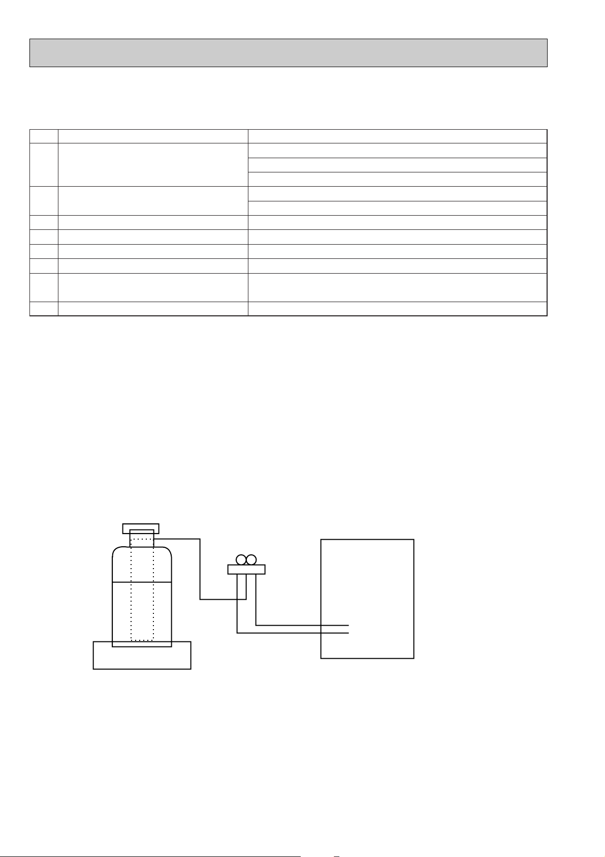
Gravimeter
Unit
[1] Service tools
Use the below service tools as exclusive tools for R407C refrigerant.
No. Tool name Specifications
1 Gauge manifold ·Only for R407C.
·Use the existing fitting SPECIFICATIONS. (UNF7/16)
·Use high-tension side pressure of 3.43MPa·G or over.
2 Charge hose ·Only for R407C.
·Use pressure performance of 5.10MPa·G or over.
3 Electronic scale
4 Gas leak detector ·Use the detector for R407C.
5 Adapter for reverse flow check. ·Attach on vacuum pump.
6 Refrigerant charge base.
7 Refrigerant cylinder. ·For R407C ·Top of cylinder (Brown)
·Cylinder with syphon
8 Refrigerant recovery equipment.
[2] Notice on repair service
·After recovering the all refrigerant in the unit, proceed to working.
·Do not release refrigerant in the air.
·After completing the repair service, recharge the cycle with the specified amount of
liquid refrigerant.
[3] Refrigerant recharging
(1) Refrigerant recharging process
1Direct charging from the cylinder.
·R407C cylinder are available on the market has a syphon pipe.
·Leave the syphon pipe cylinder standing and recharge it.
(By liquid refrigerant)
(2) Recharge in refrigerant leakage case
·After recovering the all refrigerant in the unit, proceed to working.
·Do not release the refrigerant in the air.
·After completing the repair service, recharge the cycle with the specified amount of
liquid refrigerant.
4
Page 5

4
Air outlet
Intake grille
Air intake
Left/right guide vanes
Change the direction of airflow
from the horizontal blower.
Long-life fillter
Removes dust and foreigh matter from air coming in
through the grille (Recommended cleaning interval :
Approx, every 2,500 operating hours)
Up/down guide vanes
Change the direction of airflow from the
vartical blower.
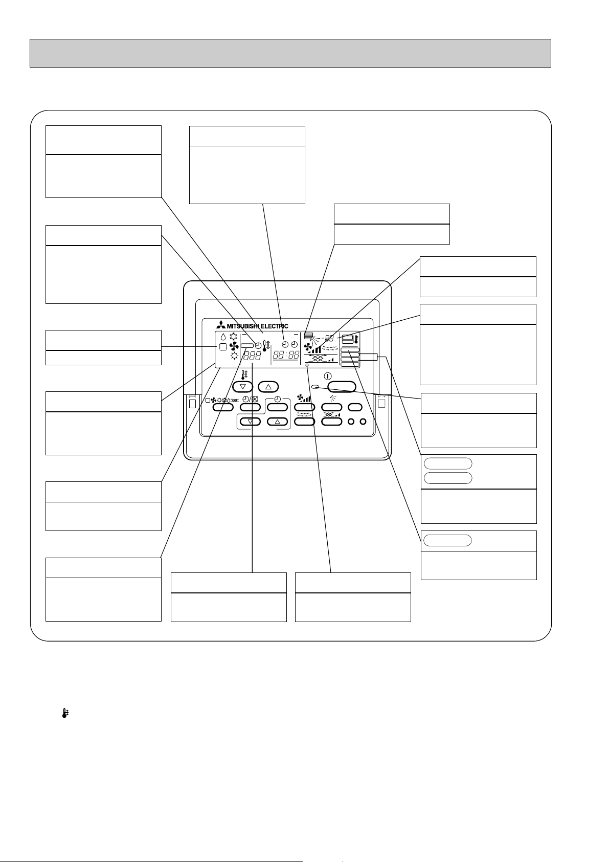
PART NAMES AND FUNCTIONS
● Indoor (Main) Unit
● Remote controller
Once the controls are set, the same operation mode can be repeated by simply pressing the ON/OFF button.
PCH-P2/2.5/3/4/5/6GAH
PCA-P2/2.5/3/4/5/6GA
● Operation buttons
AIR SPEED button
This sets the fan speed.
VENTILATION button
This set the ventilation fan speed.
ON/OFF button
This switches between the operation and stop modes each time it is
pressed. The lamp on this button
lights during operation.
AIR DIRECTION button
This adjusts the vertical angle of
the ventilation.
FILTER button
This resets the filter service indication display.
CHECK-TEST RUN button
Only press this button to perform
an inspection check or test operation Do not use it for normal operation.
TIMER button
This switches between continuous
operation and the timer operation.
OPERATION SWITCH button
Press this button to switch the
cooler electronic dry (dehumidify)
automatic and heater modes.
TEMP. ADJUSTMENT button
This sets the room temperature
The temperature setting can be
performed in 1°C units
Setting range
Cooler 19°C to 30°C
Heater 17°C to 28°C
TIMER ADJUSTMENT
button
This adjust the current time, start
time and stop time.
TIME SETTING button
This sets of switches the current
time. start time and stop time.
LOUVER button
This switches the horizontal fan
motion ON and OFF.
(This button does not operate in
this model)
5
Page 6

● Display
CENTRALLY
CONTROLLED display
This indicates when the unit is con-
trolled by optional features such as
central control type remote controller.
TIMER display
This indicates when the continuous
operation and time operation modes
are set.
It also display the time for the timer
operation at the same time as when
it is set.
OPERATION MODE display
This indicates the operation mode.
STANDBY display
This indicates when the standby
mode is set from the time the sleep
operation starts until the heating air
is discharged.
DEFROST display
This indicates when the defrost oper-
ation is performed.
CLOCK display
The current time , start time and stop
time can be displayed in ten second
intervals by pressing the time switch
button. The start time or stop time is
always displayed during the timer
operation.
In this display example on the bottom left, a condition where all display lamps light is shown for explanation purposes although this differs
from actual operation.
AIR DIRECTION display
This displays the air direction.
FAN SPEED display
The selected fan speed is displayed.
ROOM TEMPERATURE display
The temperature of the suction air is
displayed during operation. The display range is 8° to 39°C. The display
flashes 8°C when the actual temperature is less than 8° and flashes
39°C when the actual temperature is
greater than 39°C.
Operation lamp
This lamp lights during operation,
goes off when the unit stops and
flashes when a malfunction occurs.
CHECK MODE
TEST RUN
This display lights in the check mode
or when a test operation is performed.
display
CHECK display
This indicates when a malfunction
has occurred in the unit which should
be checked.
SET TEMPERATURE display
This displays the selected setting
temperature.
FILTER
This lamp lights when the filter need
to be cleaned.
POWER display
This lamp lights when electricity is
supplied to the unit.
display
Caution
● Only the Power display lights when the unit is stopped and power supplied to the unit.
● When power is turned ON for the first time the (CENTRAL CTRL) display appears to go off momentarily but this is not a
malfunction.
● When the central control remote control unit, which is sold separately, is used the ON-OFF button, operation switch button
and TEMP. adjustment button do not operate.
● “NOT AVAILABLE” is displayed when the Air speed button are pressed.This indicates that this room unit is not equipped
with the fan direction adjustment function and the louver function.
● When power is turned ON for the first time, it is normal that “H0” is displayed on the room temperature indication (For max.
2minutes). Please wait until this “H0” indication disappear then start the operation.
6
Page 7

● Remote controller
PAR-20MAA
ON/OFF
CENTRALLY CONTROLLED
ERROR CODE
CLOCK
ON OFF
˚C
CHECK
CHECK MODE
FILTER
TEST RUN
FUNCTION
˚C
1Hr.
NOT AVAILABLE
STAND BY
DEFROST
FILTER
CHECK TEST
TEMP.
TIMER SET
Press this button to switch the cooler,
electronic dry (dehumidify), automatic
and heater modes.
OPERATION SWITCH button
This sets the room temperature. The
temperature setting can be performed
in 1: units
Setting range
Cooler 19: to 30:
Heater 17: to 28:
TEMP. ADJUSTMENT button
This switches between continuous
operation and the timer operation.
TIMER button
This switches between the operation
and stop modes each time it is pressed.
The lamp on this button lights during
operation.
ON/OFF button
Only press this button to perform an
inspection check or test operation.
Do not use it for normal operation.
CHECK-TEST RUN button
This switch the horizontal fan motion
ON and OFF.
(Not available for this model.)
LOUVER button
This sets the ventilation fan speed.
VENTILATION button
This adjusts the vertical angle of the
ventilation.
AIR DIRECTION button
This resets the filter service indication
display
FILTER button
This sets the current time, start time
and stop time.
TIME SETTING button
This sets the ventilation fan speed.
AIR SPEED button
Once the controls are set, the same operation mode can be repeated by simply pressing the ON/OFF button.
PCH-P2/2.5/3/4/5/6GAH1
PCA-P2/2.5/3/4/5/6GA1
● Operation buttons
7
Page 8
PAR-20MAA
ON/OFF
CENTRALLY CONTROLLED
ERROR CODE
CLOCK
ON OFF
˚C
CHECK
CHECK MODE
FILTER
TEST RUN
FUNCTION
˚C
1Hr.
NOT AVAILABLE
STAND BY
DEFROST
FILTER
CHECK TEST
TEMP.
TIMER SET
● Display
CENTRALLY
CONTROLLED display
This indicates when the unit is controlled by optional features such as
central control type remote controller.
TIMER display
This indicates when the continuous
operation and time operation modes
are set.
It also display the time for the timer
operation at the same time as when
it is set.
OPERATION MODE display
This indicates the operation mode.
STANDBY display
This indicates when the standby
mode is set from the time the sleep
operation starts until the heating air
is discharged.
DEFROST display
This indicates when the defrost operation is performed.
CLOCK display
The current time , start time and stop
time can be displayed in ten second
intervals by pressing the time switch
button. The start time or stop time is
always displayed during the timer
operation.
In this display example on the bottom left, a condition where all display lamps light is shown for explanation purposes although this differs
from actual operation.
AIR DIRECTION display
This displays the air direction.
FAN SPEED display
The selected fan speed is displayed.
ROOM TEMPERATURE display
The temperature of the suction air is
displayed during operation. The display range is 8° to 39°C. The display
flashes 8°C when the actual temperature is less than 8° and flashes
39°C when the actual temperature is
greater than 39°C.
Operation lamp
This lamp lights during operation,
goes off when the unit stops and
flashes when a malfunction occurs.
CHECK MODE
TEST RUN
This display lights in the check mode
or when a test operation is performed.
display
CHECK display
This indicates when a malfunction
has occurred in the unit which should
be checked.
SET TEMPERATURE display
This displays the selected setting
temperature.
FILTER
This lamp lights when the filter need
to be cleaned.
POWER display
This lamp lights when electricity is
supplied to the unit.
display
Caution
● Only the Power display lights when the unit is stopped and power supplied to the unit.
● When power is turned ON for the first time the (CENTRAL CTRL) display appears to go off momentarily but this is not a
malfunction.
● When the central control remote control unit, which is sold separately, is used the ON-OFF button, operation switch button
and TEMP. adjustment button do not operate.
● “NOT AVAILABLE” is displayed when the Air speed button are pressed.This indicates that this room unit is not equipped
with the fan direction adjustment function and the louver function.
● When power is turned ON for the first time, it is normal that “H0” is displayed on the room temperature indication (For max.
2minutes). Please wait until this “H0” indication disappear then start the operation.
8
Page 9

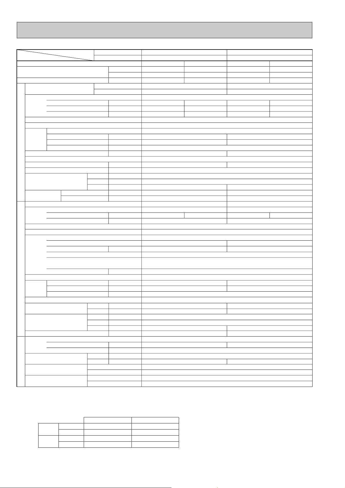
5
Service Ref.
With Electric heater
Without Electric heater
With Electric heater
Without Electric heater
With Electric heater
Without Electric heater
Item
Btu/h
W
kW
kW
A
A
kW
K/min(CFM)
Pa(mmAq)
kW
dB
mm(in.)
mm(in.)
mm(in.)
mm(in.)
kg(lbs)
kg(lbs)
A
A
kW
W
kW
K
/min(CFM
)
dB
dB
mm(in.)
mm(in.)
mm(in.)
kg(lbs)
kg(lbs)
L
mm(in.)
mm(in.)
Function
Capacity w1
Total input w1
Service Ref.
Power supply
Input w2
Running current w2
Starting current w2
External finish
Heat exchanger
Fan Fan(drive) x No.
Fan motor output
Airflow(Lo-Mi2-Mi1-Hi)
External static pressure
Booster heater w2
Operation control & Thermostat
Noise level(Lo-Mi2-Mi1-Hi)
Unit drain pipe I.D.
Dimensions
Weight
Service Ref.
Power supply
Running current
Starting current
External finish
Refrigerant control
Compressor
Model
Motor output
Starter type
Protection devices
Crankcase heater
Heat exchanger
Fan Fan(drive) x No.
Fan motor output
Airflow
Defrost method
Noise level
Dimensions
Weight
Refrigerant
Charge
Oil (Model)
Pipe size O.D.
Connection method
Between the indoor &
outdoor unit
INDOOR UNITOUTDOOR UNIT
REFRIGERANT PIPING
PCH-P2GAH
PCA-P2GA
PCH-P2GAH
PCA-P2GA
PCH-P2.5GAH
PCA-P2.5GA
PCH-P2.5GAH
PCA-P2.5GA
Cooling
18,800
5,500
2.58
0.10
0.43
1.20
11.11 / 3.88
Cooling
23,900
7,000
2.76
0.13
0.55
1.27
11.78 / 4.11
Heating
22,300 (27,100)
6,550 (7,950)
2.67 (4.07)
0.10 <1.40>
0.43 <5.83>
1.20 <5.83>
11.51 / 4.02
Heating
24,900 (32,100)
7,300 (9,400)
2.71 (4.81)
0.13 <2.10>
0.55 <8.75>
1.27 <8.75>
11.55 / 4.03
W
D
H
Cooling
Heating
W
D
H
Liquid
Gas
Indoor side
Outdoor side
Height difference
Piping length
Notes1. Rating Conditions (ISO T1)
Cooling : Indoor : D.B. 27˚C(80˚F), W.B. 19˚C (66˚F) Outdoor : D.B. 35˚C(95˚F), W.B. 24˚C (75˚F)
Heating : Indoor : D.B. 20˚C(68˚F) Outdoor : D.B. 7˚C(45˚F), W.B. 6˚C (43˚F)
Refrigerant piping length (one way) : 5m (16ft)
2. Guaranteed operating range
3. Above data based on indicated voltage
Indoor Unit Single phase 240V 50Hz
Outdoor Unit Single phase 240V 50Hz / 3 phase 415V 50Hz
Upper limit
Lower limit
Upper limit
Lower limit
Indoor
D.B. 35˚C, W.B. 22.5˚C
D.B. 19˚C, W.B. 15˚C
D.B. 28˚C
D.B. 17˚C
Outdoor
D.B. 46˚C
D.B. -5˚C
D.B. 24˚C, W.B. 18˚C
D.B. -11˚C, W.B. -12˚C
Cooling
Heating
w1 : ( ) Shows the total rating.
w2 : < > Shows the only booster heater rating.
Sirocco (direct) x 2
0.054
10-11-12-13 (353-338-424-459)
<1.4>
37-38-40-42
1,000 (39-3/8)
28.5 (63)
27 (60)
PUH-P2VGA / PUH-P2YGA
74 / 30
NE38VMJM / NE38YEJM
1.7
0.070
55(1,940)
48
49
71(157)
3.1(6.8)
Max. 40m
Max. 40m
Sirocco (direct) x 3
0.07
14-15-16-18 (494-530-565-635)
<2.1>
37-39-41-43
1,310 (51-9/16)
36 (79)
34 (75)
PUH-P2.5VGA
1 / PUH-P2.5YGA1
77 / 32
NE41VMJM / NE41YEJM
1.9
0.070
50(1,770)
48
50
82(181)
3.3(7.3)
Max. 50m
Max. 50m
Single phase, 50Hz, 220-230-240V
Munsell 0.70Y 8.59 / 0.97
Plate fin coil
0 (direct blow)
Remote controller & built-in
26 (1)
680 (26-3/4)
210 (8-1/4)
Single phase, 50Hz, 220-230-240V / 3 phases, 50Hz, 380-400-415V (4wires)
Munsell 5Y 8/1
Linear Expansion Valve
Hermetic
Line start
Inner thermostat, HP switch, Discharge thermo. / Thermal relay, Discharge thermo, HP switch, Anti-phase protector.
38
Plate fin coil
Propeller (direct) x 1
Reverse cycle
900(35-7/16)
330+20(13+3/4)
855(33-5/8)
R407C
1.2 (Ester)MEL56
9.52 (3/8)
15.88 (5/8)
Flared
Flared
SPECIFICATIONS
1. Heat pump type Rating Conditions (ISO T1)
9
Page 10
Rating Conditions (ISO T1)
Service Ref.
With Electric heater
Without Electric heater
With Electric heater
Without Electric heater
With Electric heater
Without Electric heater
Item
Btu/h
W
kW
kW
A
A
kW
K/min(CFM)
Pa(mmAq)
kW
dB
mm(in.)
mm(in.)
mm(in.)
mm(in.)
kg(lbs)
kg(lbs)
A
A
kW
W
kW
K
/min(CFM
)
dB
dB
mm(in.)
mm(in.)
mm(in.)
kg(lbs)
kg(lbs)
L
mm(in.)
mm(in.)
Function
Capacity w1
Total input w1
Service Ref.
Power supply
Input w2
Running current w2
Starting current w2
External finish
Heat exchanger
Fan Fan(drive) x No.
Fan motor output
Airflow(Lo-Mi2-Mi1-Hi)
External static pressure
Booster heater w2
Operation control & Thermostat
Noise level(Lo-Mi2-Mi1-Hi)
Unit drain pipe I.D.
Dimensions
Weight
Service Ref.
Power supply
Running current
Starting current
External finish
Refrigerant control
Compressor
Model
Motor output
Starter type
Protection devices
Crankcase heater
Heat exchanger
Fan Fan(drive) x No.
Fan motor output
Airflow
Defrost method
Noise level
Dimensions
Weight
Refrigerant
Charge
Oil (Model)
Pipe size O.D.
Connection method
Between the indoor &
outdoor unit
INDOOR UNITOUTDOOR UNIT
REFRIGERANT PIPING
PCH-P3GAH
PCA-P3GA
PCH-P3GAH
PCA-P3GA
PCH-P4GAH
PCA-P4GA
PCH-P4GAH
PCA-P4GA
Cooling
25,600
7,500
3.47
0.13
0.55
1.27
14.64 / 5.46
Cooling
33,100
9,700
3.52
0.16
0.70
1.48
5.49
Heating
31,700 (38,900)
9,300 (11,400)
3.65 (5.75)
0.13 <2.10>
0.55 <8.75>
1.27 <8.75>
15.43 / 5.76
Heating
36,300 (45,600)
10,650 (13,350)
3.70 (6.40)
0.16 <2.70>
0.70 <11.25>
1.48 <11.25>
5.79
W
D
H
Cooling
Heating
W
D
H
Liquid
Gas
Indoor side
Outdoor side
Height difference
Piping length
0.07
14-15-16-18 <494-530-565-635>
<2.1>
37-39-41-43
210 (8-1/4)
36 (79)
34 (75)
PUH-P3VGA / PUH-P3YGA
Single phase, 50Hz, 220-230-240V / 3 phase, 50Hz, 380-400-415V (4wires)
93 / 41
NE52VNJM / NE52YDJM
2.5
Propeller (direct) x 1
0.070
50 (1,770)
49
51
855 (33-5/8)
82 (181)
3.7 (8.2)
15.88 (5/8)
0.09
20-21-23-25 <706-741-812-883>
<2.7>
40-41-43-45
270 (10-5/8)
39.5 (87)
37 (82)
PUH-P4YGA
3 phase, 50Hz, 380-400-415V (4wires)
45
NE56YDJM
2.7
Propeller (direct) x 2
0.070+0.070
85 (3,000)
51
53
1,260 (49-5/8)
96 (212)
4.0 (8.8)
19.05 (3/4)
Single phase, 50Hz, 220-230-240V
Munsell 0.70Y 8.59 / 0.97
Plate fin coil
Sirocco (direct) x 3
0 (direct blow)
Remote controller & built-in
26 (1)
1,310 (51-9/16)
680 (26-3/4)
Munsell 5Y 8/1
Linear Expansion Valve
Hermetic
Line start
38
Plate fin coil
Reverse cycle
900 (35-7/16)
330+20 (13+3/4)
R407C
1.6 (Ester)MEL56
9.52 (3/8)
Flared
Flared
Max. 50m
Max. 50m
VGA...Inner thermostat, HP switch, Discharge thermo.
YGA...Thermal relay, Discharge thermo, HP switch, Anti-phase protector.
Notes1. Rating Conditions (ISO T1)
Cooling : Indoor : D.B. 27˚C(80˚F), W.B. 19˚C (66˚F) Outdoor : D.B. 35˚C(95˚F), W.B. 24˚C (75˚F)
Heating : Indoor : D.B. 20˚C(68˚F) Outdoor : D.B. 7˚C(45˚F), W.B. 6˚C (43˚F)
Refrigerant piping length (one way) : 5m (16ft)
2. Guaranteed operating range
3. Above data based on indicated voltage
Indoor Unit Single phase 240V 50Hz
Outdoor Unit Single phase 240V 50Hz / 3 phase 415V 50Hz
Upper limit
Lower limit
Upper limit
Lower limit
Indoor
D.B. 35˚C, W.B. 22.5˚C
D.B. 19˚C, W.B. 15˚C
D.B. 28˚C
D.B. 17˚C
Outdoor
D.B. 46˚C
D.B. -5˚C
D.B. 24˚C, W.B. 18˚C
D.B. -11˚C, W.B. -12˚C
Cooling
Heating
w1 : ( ) Shows the total rating.
w2 : < > Shows the only booster heater rating.
10
Page 11

Rating Conditions (ISO T1)
Service Ref.
With Electric heater
Without Electric heater
With Electric heater
Without Electric heater
With Electric heater
Without Electric heater
Item
Btu/h
W
kW
kW
A
A
kW
K/min(CFM)
Pa(mmAq)
kW
dB
mm(in.)
mm(in.)
mm(in.)
mm(in.)
kg(lbs)
kg(lbs)
A
A
kW
W
kW
K
/min(CFM
)
dB
dB
mm(in.)
mm(in.)
mm(in.)
kg(lbs)
kg(lbs)
L
mm(in.)
mm(in.)
Function
Capacity w1
Total input w1
Service Ref.
Power supply
Input w2
Running current w2
Starting current w2
External finish
Heat exchanger
Fan Fan(drive) x No.
Fan motor output
Airflow(Lo-Mi2-Mi1-Hi)
External static pressure
Booster heater w2
Operation control & Thermostat
Noise level(Lo-Mi2-Mi1-Hi)
Unit drain pipe I.D.
Dimensions
Weight
Service Ref.
Power supply
Running current
Starting current
External finish
Refrigerant control
Compressor
Model
Motor output
Starter type
Protection devices
Crankcase heater
Heat exchanger
Fan Fan(drive) x No.
Fan motor output
Airflow
Defrost method
Noise level
Dimensions
Weight
Refrigerant
Charge
Oil (Model)
Pipe size O.D.
Connection method
Between the indoor &
outdoor unit
INDOOR UNITOUTDOOR UNIT
REFRIGERANT PIPING
PCH-P5GAH
PCA-P5GA
PCH-P5GAH
PCA-P5GA
PCH-P6GAH
PCA-P6GA
PCH-P6GAH
PCA-P6GA
Cooling
43,700
12,800
5.49
0.24
1.06
2.20
8.39
Cooling
49,500
14,500
6.60
0.24
1.06
2.20
10.17
Heating
54,600 (64,800)
16,000 (19,000)
5.71 (8.71)
0.24 <3.00>
1.06 <12.50>
2.20 <12.50>
8.74
Heating
57,300 (67,600)
16,800 (19,800)
6.67 (9.67)
0.24 <3.00>
1.06 <12.50>
2.20 <12.50>
10.28
W
D
H
Cooling
Heating
W
D
H
Liquid
Gas
Indoor side
Outdoor side
Height difference
Piping length
41-43-45-46
46 (101)
43 (95)
PUH-P5YGA
79
HE86YAA
4.3
95 (3,360)
53
55
42-44-46-48
48 (106)
45 (99)
PUH-P6YGA
84
HE101YAA
5.1
100 (3,530)
55
57
Single phase, 50Hz, 220-230-240V
Munsell 0.70Y 8.59 / 0.97
Plate fin coil
Sirocco (direct) x 4
0.15
27-30-32-34 <953-1,059-1,130-1,200>
0 (direct blow)
<3.0>
Remote controller & built-in
26 (1)
1,620 (63-3/4)
680 (26-3/4)
270 (10-5/8)
3 Phase, 50Hz, 380-400-415V(4wires)
Munsell 5Y 8/1
Linear Expansion Valve
Hermetic
Line start
Anti-phase protector, Internal thermostat, LP switch, HP switch,Thermal relay,Discharge thermo
38
Plate fin coil
Propeller (direct) x 2
0.075+0.075
Reverse cycle
1050 (41-5/16)
330+20 (13+3/4)
1,260 (49-5/8)
122 (269)
R407C
5.8 (12.8)
2.0 (Ester)MEL32
9.52 (3/8)
19.05 (3/4)
Flared
Flared
Max. 50m
Max. 50m
Notes1. Rating Conditions (ISO T1)
Cooling : Indoor : D.B. 27˚C(80˚F), W.B. 19˚C (66˚F) Outdoor : D.B. 35˚C(95˚F), W.B. 24˚C (75˚F)
Heating : Indoor : D.B. 20˚C(68˚F) Outdoor : D.B. 7˚C(45˚F), W.B. 6˚C (43˚F)
Refrigerant piping length (one way) : 5m (16ft)
2. Guaranteed operating range
3. Above data based on indicated voltage
Indoor Unit Single phase 240V 50Hz
Outdoor Unit Single phase 240V 50Hz / 3 phase 415V 50Hz
Upper limit
Lower limit
Upper limit
Lower limit
Indoor
D.B. 35˚C, W.B. 22.5˚C
D.B. 19˚C, W.B. 15˚C
D.B. 28˚C
D.B. 17˚C
Outdoor
D.B. 46˚C
D.B. -5˚C
D.B. 24˚C, W.B. 18˚C
D.B. -11˚C, W.B. -12˚C
Cooling
Heating
w1 : ( ) Shows the total rating.
w2 : < > Shows the only booster heater rating.
11
Page 12

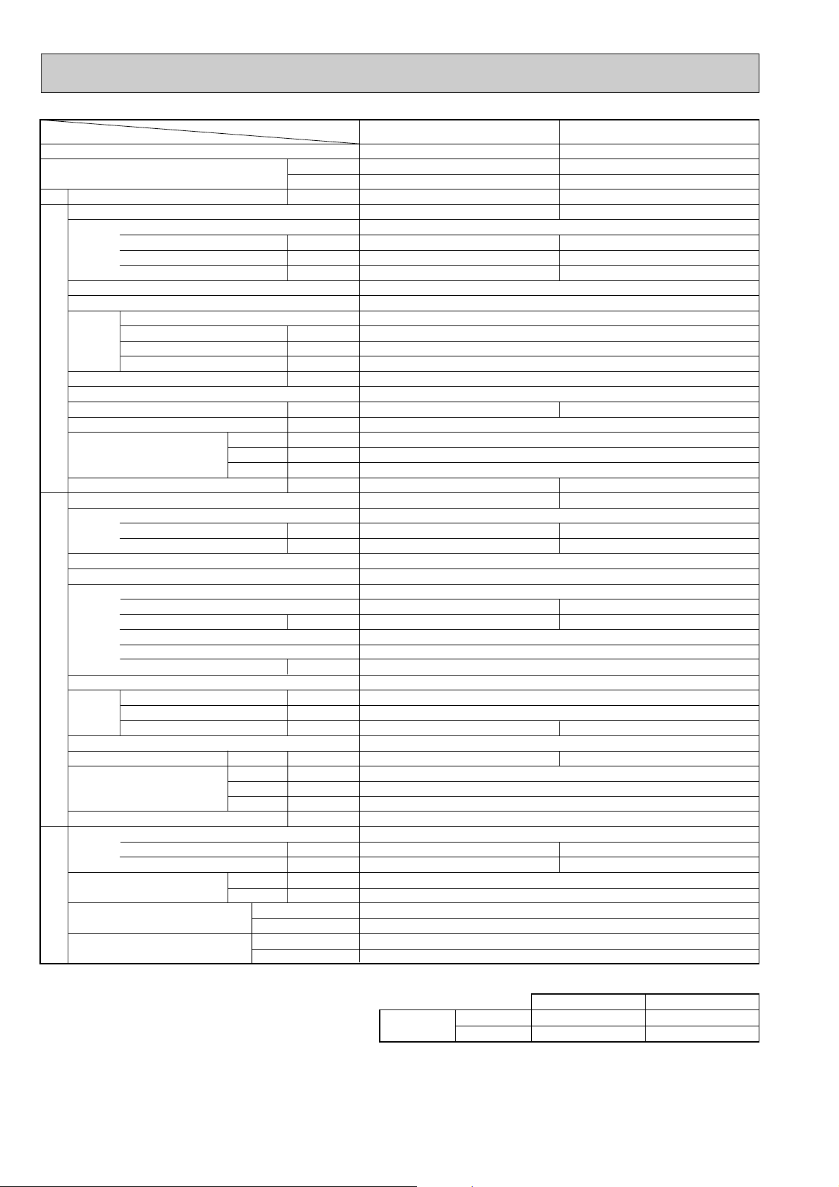
2. Cooling only type Rating Conditions (ISO T1)
OUTDOOR UNIT
REFRIGERANT
PIPING
Service Ref.
Power supply
External finish
Heat exchanger
Fan
Booster heater
Operation control & Thermostat
Noise level(Lo-Mi2-Mi1-Hi)
Unit drain pipe I.D.
Dimensions
Weight
Service Ref.
Power supply
External finish
Refrigerant control
Compressor
Heat exchanger
Fan
Defrost method
Noise level
Dimensions
Weight
Refrigerant
Pipe size O.D.
Connection method
Between the indoor & outdoor unit
Indoor side
Outdoor side
Height difference
Piping length
Liquid
Gas
Cooling
mm(in.)
mm(in.)
kg(lbs)
dB
mm(in.)
mm(in.)
mm(in.)
kg(lbs)
W
D
H
kW
K/min <CFM>
kW
L
Input
Running current
Starting current
Fan(drive))No.
Fan motor output
Airflow(Lo-Mi2-Mi1-Hi)
External static pressure
Running current
Starting current
Model
Motor output
Starter type
Protection devices
Crankcase heater
Fan(drive))No.
Fan motor output
Airflow
Charge
Compressor oil (Model)
A
A
dB
mm(in.)
mm(in.)
mm(in.)
mm(in.)
kg(lbs)
W
D
H
kW
K/min <CFM>
Pa(mmAq)
kW
kW
A
A
Btu/h
W
kW
Item
Service Ref.
Function
Total input
PCA-P2GA PCA-P2.5GA
Cooling
18,800
5,500
2.58
Cooling
23,900
7,000
2.76
PCA-P2GA
Single phase, 50Hz, 220-230-240V
PCA-P2.5GA
0.10
0.43
1.20
0.13
0.55
1.27
Munsell 0.70Y 8.59 / 0.97
Plate fin coil
Sirocco (direct))2
0.054
10 -11-12-13 <353-338-424-459>
Sirocco (direct))3
0.07
14 -15-16-18 <494-530-565-635>
0 (direct blow)
——
Remote controller & built-in
37-38-40-42 37-39-41-43
26(1)
1,000(39-3/8) 1,310(51-9/16)
680(26-3/4)
210(8-1/4)
27(60)
PU-P2VGA
34(75)
PU-P2.5VGA
1
Single phase, 50Hz, 220-230-240V
11.11
74
11.78
77
Munsell 5Y 8/1
Linear Expansion Valve
Hermetic
NE38VMJM
1.7
NE41VMJM
1.9
Line start
Internal thermostat. High-pressure switch,Discharge thermo.
38
Plate fin coil
Propeller (direct)✕1
0.070
55 (1,940) 50 (1,770)
48
—
71 (157) 82 (181)
900 (35-7/16)
330+20 (13+3/4)
R407C
3.1 (6.8) 3.3 (7.3)
1.2 (Ester)MEL56
855 (33-5/8)
9.52 (3/8)
15.88 (5/8)
Flared
Flared
Max. 40m
Max. 40m
Max. 50m
Max. 50m
Upper limit
Lower limit
Indoor
D.B. 35:, W.B. 22.5:
D.B. 19:, W.B. 15:
Outdoor
D.B. 46:
D.B. -5:
Cooling
INDOOR UNIT
W
Capacity
2. Guaranteed operating range
Notes1. Rating Conditions (ISO T1)
Cooling : Indoor : D.B. 27:(80
Outdoor : D.B. 35:(95
Refrigerant piping length (one way) : 5m(16ft)
3. Above data based on indicated voltage
Indoor Unit Single phase 240V 50Hz
Outdoor Unit Single phase 240V 50Hz
o
F), W.B. 19:(66oF)
o
F), W.B. 24:(75oF)
12
Page 13

Rating Conditions (ISO T1)
Item
Function
Capacity
Total input
Service Ref.
Power supply
Input
Running current
Starting current
External finish
Heat exchanger
Fan
Booster heater
INDOOR UNIT
Operation control & Thermostat
Noise level(Lo-Mi2-Mi1-Hi)
Unit drain pipe I.D.
Dimensions
Weight
Service Ref.
Power supply
External finish
Refrigerant control
Compressor
Heat exchanger
Fan
OUTDOOR UNIT
Defrost method
Noise level
Dimensions
Weight
Refrigerant
Pipe size O.D.
PIPING
Connection method
Fan(drive))No.
Fan motor output
Airflow(Lo-Mi2-Mi1-Hi)
External static pressure
Running current
Starting current
Model
Motor output
Starter type
Protection devices
Crankcase heater
Fan(drive))No.
Fan motor output
Airflow
Charge
Compressor oil (Model)
REFRIGERANT
Between the indoor & outdoor unit
Service Ref.
K/min <CFM>
W
D
H
K/min <CFM>
Cooling
W
D
H
Liquid
Gas
Indoor side
Outdoor side
Height difference
Piping length
Btu/h
W
kW
kW
A
A
kW
Pa(mmAq)
kW
dB
mm(in.)
mm(in.)
mm(in.)
mm(in.)
kg(lbs)
A
A
kW
W
kW
dB
mm(in.)
mm(in.)
mm(in.)
kg(lbs)
kg(lbs)
L
mm(in.)
mm(in.)
PCA-P3GA PCA-P4GA
Cooling
25,600
7,500
3.47
PCA-P3GA
Single phase, 50Hz, 220-230-240V
0.13
0.55
1.27
Munsell 0.70Y 8.59 / 0.97
Plate fin coil
Sirocco (direct) ✕ 3
0.07
14-15-16-18 <494-530-565-635>
0 (direct blow)
Remote controller & built-in
37-39-41-43 40-41-43-45
1,310 (51-9/16)
680 (26-3/4)
210 (8-1/4) 270 (10-5/8)
34 (75)
PU-P3VGA / PU-P3YGA
Single-phase, 50Hz, 220-230-240V / 3-phase, 50Hz,380-400-415V (4wires)
14.64 / 5.46
93 / 41
Munsell 5Y 8/1
Linear Expansion Valve
Hermetic
NE52VNJM / NE52YDJM
2.5
VGA...Inner thermostat. High-pressure switch Discharge thermo
YGA...Anti-phase protector, Thermal relay, Discharge thermo, High-pressure switch
Propeller (direct) ✕ 1
0.070
50 (1,770)
49 51
855 (33-5/8)
82 (181)
3.7 (8.2) 4.0 (8.8)
15.88 (5/8) 19.05 (3/4)
Line start
Plate fin coil
900 (35-7/16)
330 + 20 (13+3/4)
1.6 (Ester) MEL56
9.52 (3/8)
Max. 50m
Max. 50m
20-21-23-25<706-741-812-883>
—
26 (1)
3-phase, 50Hz,380-400-415V (4wires)
38
—
R407C
Flared
Flared
Cooling
33,100
9,700
3.52
PCA-P4GA
0.16
0.70
1.48
0.09
37 (82)
PU-P4YGA
5.49
45
NE56YDJM
2.7
Propeller (direct) ✕ 2
0.070+0.070
85 (3,000)
1,260 (49-5/8)
96 (212)
Notes1. Rating Conditions (ISO T1)
Cooling : Indoor : D.B. 27:(80
Outdoor : D.B. 35:(95
Refrigerant piping length (one way) : 5m(16ft)
3. Above data based on indicated voltage
Indoor Unit Single phase 240V 50Hz
Outdoor Unit Single phase 240V 50Hz / 3 phase 415V 50Hz
o
F), W.B. 19:(66oF)
o
F), W.B. 24:(75oF)
2. Guaranteed operating range
Cooling
Upper limit
Lower limit
13
Indoor
D.B. 35:, D.B. 22.5:
D.B. 19:, D.B. 15:
Outdoor
D.B. 46:
D.B. -5:
Page 14

Rating Conditions (ISO T1)
OUTDOOR UNIT
REFRIGERANT
PIPING
Service Ref.
Power supply
External finish
Heat exchanger
Fan
Booster heater
Operation control & Thermostat
Noise level(Lo-Mi2-Mi1-Hi)
Unit drain pipe I.D.
Dimensions
Weight
Service Ref.
Power supply
External finish
Refrigerant control
Compressor
Heat exchanger
Fan
Defrost method
Noise level
Dimensions
Weight
Refrigerant
Pipe size O.D.
Connection method
Between the indoor & outdoor unit
Indoor side
Outdoor side
Height difference
Piping length
Liquid
Gas
Cooling
mm(in.)
mm(in.)
kg(lbs)
dB
mm(in.)
mm(in.)
mm(in.)
kg(lbs)
W
D
H
kW
K/min <CFM>
kW
L
Input
Running current
Starting current
Fan(drive))No.
Fan motor output
Airflow(Lo-Mi2-Mi1-Hi)
External static pressure
Running current
Starting current
Model
Motor output
Starter type
Protection devices
Crankcase heater
Fan(drive))No.
Fan motor output
Airflow
Charge
Compressor oil (Model)
A
A
dB
mm(in.)
mm(in.)
mm(in.)
mm(in.)
kg(lbs)
W
D
H
kW
K/min <CFM>
Pa(mmAq)
kW
kW
A
A
Btu/h
W
kW
Item
Service Ref.
Function
Total input
Upper limit
Lower limit
Indoor
D.B. 35:, W.B. 22.5:
D.B. 19:, W.B. 15:
Outdoor
D.B. 46:
D.B. -5:
Cooling
PCA-P5GA PCA-P6GA
Cooling
43,700
12,800
5.49
0.24
1.06
2.20
0.24
1.06
2.20
Cooling
49,500
14,500
6.60
PCA-P5GA
Single phase, 50Hz, 220-230-240V
PCA-P6GA
Munsell 0.70Y 8.59 / 0.97
Plate fin coil
Sirocco (direct)✕4
0.15
27-30-32-34 <953-1,059-1,130-1,200>
0 (direct blow)
—
Remote controller & built-in
41-43-45-46 42-44-46-48
26 (1)
1,620 (63-3/4)
680 (26-3/4)
270 (10-5/8)
43 (95)
PU-P5YGA
45 (99)
PU-P6YGA
HE86YAA
4.3
HE101YAA
5.1
95 (3,360) 100 (3,530)
122 (269)
53 55
3 phases, 50Hz, 380-400-415V (4wires)
—
R407C
5.8 (12.8)
2.0 (Ester)MEL32
1050 (41-5/16)
330+20 (13+3/4)
1,260 (49-5/8)
Munsell 5Y 8/1
Linear Expansion Valve
Hermetic
Line start
Anti-phase protector, Internal thermostat, LP switch, HP switch,Thermal relay,Discharge thermo
38
Plate fin coil
Propeller (direct)✕2
0.075+0.075
8.39
79
10.17
84
9.52 (3/8)
19.05 (3/4)
Flared
Flared
Max. 50m
Max. 50m
INDOOR UNIT
W
Capacity
2. Guaranteed operating range
Notes1. Rating Conditions (ISO T1)
Cooling : Indoor : D.B. 27:(80
Outdoor : D.B. 35:(95
Refrigerant piping length (one way) : 5m(16ft)
3. Above data based on indicated voltage
Indoor Unit Single phase 240V 50Hz
Outdoor Unit 3 phase 415V 50Hz
o
F), W.B. 19:(66oF)
o
F), W.B. 24:(75oF)
14
Page 15

3. Heat pump type Rating Conditions (ISO T1)
Item
Function
Capacity w1
Total input w1
Service Ref.
Power supply
External finish
Heat exchanger
Fan Fan(drive) x No.
INDOOR UNITOUTDOOR UNIT
Booster heater w2
Operation control & Thermostat
Noise level(Lo-Mi2-Mi1-Hi)
Unit drain pipe I.D.
Dimensions
Weight
Service Ref.
Power supply
External finish
Refrigerant control
Compressor
Heat exchanger
Fan Fan(drive) x No.
Defrost method
Noise level
Dimensions
Weight
Refrigerant
Pipe size O.D.
Connection method
Between the indoor &
REFRIGERANT PIPING
outdoor unit
Notes1. Rating Conditions (ISO T1)
2. Guaranteed operating range
Input w2
Running current w2
Starting current w2
Fan motor output
Airflow(Lo-Mi2-Mi1-Hi)
External static pressure
Running current
Starting current
Model
Motor output
Starter type
Protection devices
Crankcase heater
Fan motor output
Airflow
Charge
Oil (Model)
Cooling : Indoor : D.B. 27˚C(80˚F), W.B. 19˚C (66˚F) Outdoor : D.B. 35˚C(95˚F), W.B. 24˚C (75˚F)
Heating : Indoor : D.B. 20˚C(68˚F) Outdoor : D.B. 7˚C(45˚F), W.B. 6˚C (43˚F)
Refrigerant piping length (one way) : 5m (16ft)
Cooling
Heating
Service Ref.
With Electric heater
Without Electric heater
Upper limit
Lower limit
Upper limit
Lower limit
With Electric heater
Without Electric heater
Btu/h
W
With Electric heater
Without Electric heater
W
D
H
Cooling
Heating
W
D
H
Liquid
Gas
Indoor side
Outdoor side
Height difference
Piping length
Indoor
D.B. 35˚C, W.B. 22.5˚C
D.B. 19˚C, W.B. 15˚C
D.B. 28˚C
D.B. 17˚C
kW
kW
A
A
kW
K/min(CFM)
Pa(mmAq)
kW
dB
mm(in.)
mm(in.)
mm(in.)
mm(in.)
kg(lbs)
kg(lbs)
A
A
kW
W
kW
/min(CFM
K
dB
dB
mm(in.)
mm(in.)
mm(in.)
kg(lbs)
kg(lbs)
L
mm(in.)
mm(in.)
)
D.B. 24˚C, W.B. 18˚C
D.B. -11˚C, W.B. -12˚C
PCH-P2GAH1
PCA-P2GA1
Cooling
18,400
5,400
2.40
PCH-P2GAH1
PCA-P2GA1
0.10
0.43
1.20
Sirocco (direct) x 2
Sirocco (direct) x 2
0.054
10-11-12-13 (353-338-424-459)
10-11-12-13 (353-338-424-459)
PUH-P2VGAA.UK / PUH-P2YGAA.UK
PUH-P2VGAA.UK / PUH-P2YGAA.UK
Single phase, 50Hz, 220-230-240V / 3 phases, 50Hz, 380-400-415V (4wires)
10.26 / 3.70
NE36VMJMT / NE36YEKMT
NE36VMJMT / NE36YEKMT
Inner thermostat, HP switch, Discharge thermo. / Thermal relay, Discharge thermo, HP switch.
Outdoor
D.B. 46˚C
D.B. -5˚C
0.054
<1.4>
<1.4>
37-38-40-42
37-38-40-42
1,000 (39-3/8)
1,000 (39-3/8)
28.5 (63)
28.5 (63)
27 (60)
27 (60)
62 / 31
62 / 31
0.070
0.070
55 (1,940)
55 (1,940)
71 (157)
71 (157)
2.6 (5.7)
2.6 (5.7)
Max. 40m
Max. 40m
Max. 40m
Max. 40m
Heating
21,300 (26,100)
6,250 (7,650)
2.40 (3.80)
Single phase, 50Hz, 220-230-240V
0.10 <1.40>
0.43 <5.83>
1.20 <5.83>
Munsell 0.70Y 8.59 / 0.97
Plate fin coil
14-15-16-18 (494-530-565-635)
26 (1)
PUH-P2.5VGAA.UK / PUH-P2.5YGAA.UK
11.90 / 4.48
38
Flared
Flared
1.6
1.6
48
48
49
49
0 (direct blow)
Remote controller & built-in
680 (26-3/4)
210 (8-1/4)
10.57 / 3.82
Munsell 5Y 7/1
Linear Expansion Valve
Hermetic
Line start
Plate fin coil
Propeller (direct) x 1
Reverse cycle
900 (35-7/16)
330+20 (13+3/4)
855 (33-5/8)
R407C
1.2 (Ester) MEL56
9.52 (3/8)
15.88 (5/8)
w1 : ( ) Shows the total rating.
w2 : < > Shows the only booster heater rating.
PCH-P2.5GAH1
PCA-P2.5GA1
Cooling
22,600
6,650
2.65
PCH-P2.5GAH1
PCA-P2.5GA1
0.13
0.55
1.27
Sirocco (direct) x 3
0.07
<2.1>
37-39-41-43
1,310 (51-9/16)
36 (79)
34 (75)
77 / 35
NE41VMJMT / NE41YEKMT
0.070
50 (1,770)
82 (181)
3.1 (6.8)
Max. 50m
Max. 50m
Heating
24,900 (32,100)
7,300 (9,400)
2.71 (4.81)
0.13 <2.10>
0.55 <8.75>
1.27 <8.75>
11.51 / 4.34
1.9
48
50
3. Above data based on indicated voltage
Indoor Unit Single phase 240V 50Hz
Outdoor Unit Single phase 240V 50Hz / 3 phase 415V 50Hz
15
Page 16

Rating Conditions (ISO T1)
Service Ref.
With Electric heater
Without Electric heater
With Electric heater
Without Electric heater
With Electric heater
Without Electric heater
Item
Btu/h
W
kW
kW
A
A
kW
K/min(CFM)
Pa(mmAq)
kW
dB
mm(in.)
mm(in.)
mm(in.)
mm(in.)
kg(lbs)
kg(lbs)
A
A
kW
W
kW
K
/min(CFM
)
dB
dB
mm(in.)
mm(in.)
mm(in.)
kg(lbs)
kg(lbs)
L
mm(in.)
mm(in.)
Function
Capacity w1
Total input w1
Service Ref.
Power supply
Input w2
Running current w2
Starting current w2
External finish
Heat exchanger
Fan Fan(drive) x No.
Fan motor output
Airflow(Lo-Mi2-Mi1-Hi)
External static pressure
Booster heater w2
Operation control & Thermostat
Noise level(Lo-Mi2-Mi1-Hi)
Unit drain pipe I.D.
Dimensions
Weight
Service Ref.
Power supply
Running current
Starting current
External finish
Refrigerant control
Compressor
Model
Motor output
Starter type
Protection devices
Crankcase heater
Heat exchanger
Fan Fan(drive) x No.
Fan motor output
Airflow
Defrost method
Noise level
Dimensions
Weight
Refrigerant
Charge
Oil (Model)
Pipe size O.D.
Connection method
Between the indoor &
outdoor unit
INDOOR UNITOUTDOOR UNIT
REFRIGERANT PIPING
PCH-P3GAH1
PCA-P3GA1
PCH-P3GAH1
PCA-P3GA1
PCH-P4GAH1
PCA-P4GA1
PCH-P4GAH1
PCA-P4GA1
Cooling
25,600
7,500
3.40
0.13
0.55
1.27
14.81 / 5.29
Cooling
33,100
9,700
3.64
0.16
0.70
1.48
15.71 / 5.55
Heating
31,300 (38,500)
9,200 (11,300)
3.50 (5.60)
0.13 <2.10>
0.55 <8.75>
1.27 <8.75>
15.76 / 5.63
Heating
36,300 (45,600)
10,650 (13,350)
3.83 (6.53)
0.16 <2.70>
0.70 <11.25>
1.48 <11.25>
16.58 / 5.86
W
D
H
Cooling
Heating
W
D
H
Liquid
Gas
Indoor side
Outdoor side
Height difference
Piping length
0.07
14-15-16-18 <494-530-565-635>
<2.1>
37-39-41-43
210 (8-1/4)
36 (79)
34 (75)
PUH-P3VGAA.UK / PUH-P3YGAA.UK
93 / 47
NE52VNJMT / NE52YDKMT
2.5
Propeller (direct) x 1
0.070
50 (1,770)
49
51
855 (33-5/8)
82 (181)
3.3 (7.3)
15.88 (5/8)
0.09
20-21-23-25 <706-741-812-883>
<2.7>
40-41-43-45
270 (10-5/8)
39.5 (87)
37 (82)
PUH-P4VGAA.UK / PUH-P4YGAA.UK
99 / 49
NE56VNJMT / NE56YDKMT
2.7
Propeller (direct) x 2
0.070+0.070
85 (3,000)
51
53
1,260 (49-5/8)
96 (212)
4.0 (8.8)
19.05 (3/4)
Single phase, 50Hz, 220-230-240V
Munsell 0.70Y 8.59 / 0.97
Plate fin coil
Sirocco (direct) x 3
0 (direct blow)
Remote controller & built-in
26 (1)
1,310 (51-9/16)
680 (26-3/4)
Munsell 5Y 7/1
Linear Expansion Valve
Hermetic
Line start
38
Plate fin coil
Reverse cycle
900 (35-7/16)
330+20 (13+3/4)
R407C
1.3 (Ester) MEL56
9.52 (3/8)
Flared
Flared
Max. 50m
Max. 50m
Inner thermostat, HP switch, Discharge thermo. /
Anti-phase protector. Thermal relay, Discharge thermo, HP switch.
Notes1. Rating Conditions (ISO T1)
Cooling : Indoor : D.B. 27˚C(80˚F), W.B. 19˚C (66˚F) Outdoor : D.B. 35˚C(95˚F), W.B. 24˚C (75˚F)
Heating : Indoor : D.B. 20˚C(68˚F) Outdoor : D.B. 7˚C(45˚F), W.B. 6˚C (43˚F)
Refrigerant piping length (one way) : 5m (16ft)
2. Guaranteed operating range
3. Above data based on indicated voltage
Indoor Unit Single phase 240V 50Hz
Outdoor Unit Single phase 240V 50Hz / 3 phase 415V 50Hz
Upper limit
Lower limit
Upper limit
Lower limit
Indoor
D.B. 35˚C, W.B. 22.5˚C
D.B. 19˚C, W.B. 15˚C
D.B. 28˚C
D.B. 17˚C
Outdoor
D.B. 46˚C
D.B. -5˚C
D.B. 24˚C, W.B. 18˚C
D.B. -11˚C, W.B. -12˚C
Cooling
Heating
w1 : ( ) Shows the total rating.
w2 : < > Shows the only booster heater rating.
Single phase, 50Hz, 220-230-240V / 3 phase, 50Hz, 380-400-415V (4wires)
16
Page 17

Rating Conditions (ISO T1)
Service Ref.
With Electric heater
Without Electric heater
With Electric heater
Without Electric heater
With Electric heater
Without Electric heater
Item
Btu/h
W
kW
kW
A
A
kW
K/min(CFM)
Pa(mmAq)
kW
dB
mm(in.)
mm(in.)
mm(in.)
mm(in.)
kg(lbs)
kg(lbs)
A
A
kW
W
kW
K
/min(CFM
)
dB
dB
mm(in.)
mm(in.)
mm(in.)
kg(lbs)
kg(lbs)
L
mm(in.)
mm(in.)
Function
Capacity w1
Total input w1
Service Ref.
Power supply
Input w2
Running current w2
Starting current w2
External finish
Heat exchanger
Fan Fan(drive) x No.
Fan motor output
Airflow(Lo-Mi2-Mi1-Hi)
External static pressure
Booster heater w2
Operation control & Thermostat
Noise level(Lo-Mi2-Mi1-Hi)
Unit drain pipe I.D.
Dimensions
Weight
Service Ref.
Power supply
Running current
Starting current
External finish
Refrigerant control
Compressor
Model
Motor output
Starter type
Protection devices
Crankcase heater
Heat exchanger
Fan Fan(drive) x No.
Fan motor output
Airflow
Defrost method
Noise level
Dimensions
Weight
Refrigerant
Charge
Oil (Model)
Pipe size O.D.
Connection method
Between the indoor &
outdoor unit
INDOOR UNITOUTDOOR UNIT
REFRIGERANT PIPING
PCH-P5GAH1
PCA-P5GA1
PCH-P5GAH1
PCA-P5GA1
PCH-P6GAH1
PCA-P6GA1
PCH-P6GAH1
PCA-P6GA1
Cooling
42,300
12,400
4.94
0.24
1.06
2.20
7.60
Cooling
48,700
14,300
5.94
0.24
1.06
2.20
9.03
Heating
50,800 (61,000)
14,900 (17,880)
5.14 (8.14)
0.24 <3.00>
1.06 <12.50>
2.20 <12.50>
8.15
Heating
58,300 (68,500)
17,100 (20,100)
6.27 (9.27)
0.24 <3.00>
1.06 <12.50>
2.20 <12.50>
9.56
W
D
H
Cooling
Heating
W
D
H
Liquid
Gas
Indoor side
Outdoor side
Height difference
Piping length
41-43-45-46
46 (101)
43 (95)
PUH-P5YGAA.UK
65.5
ZR61KCE-TFD
3.5
95 (3,360)
55
56
4.6 (10.1)
1.690 (Ester) MMMA-POE
42-44-46-48
48 (106)
45 (99)
PUH-P6YGAA.UK
74
ZR72KCE-TFD
4.2
100 (3,530)
57
58
4.9 (10.8)
1.774 (Ester) MMMA-POE
Single phase, 50Hz, 220-230-240V
Munsell 0.70Y 8.59 / 0.97
Plate fin coil
Sirocco (direct) x 4
0.15
27-30-32-34 <953-1,059-1,130-1,200>
0 (direct blow)
<3.0>
Remote controller & built-in
26 (1)
1,620 (63-3/4)
680 (26-3/4)
270 (10-5/8)
3 Phase, 50Hz, 380-400-415V (4wires)
Munsell 5Y 7/1
Linear Expansion Valve
Hermetic
Line start
Anti-phase protector, Internal thermostat, LP switch, HP switch,Thermal relay,Discharge thermo
38
Plate fin coil
Propeller (direct) x 2
0.070+0.070
Reverse cycle
1050 (41-5/16)
330+20 (13+3/4)
1,260 (49-5/8)
122 (269)
R407C
9.52 (3/8)
19.05 (3/4)
Flared
Flared
Max. 50m
Max. 50m
Notes1. Rating Conditions (ISO T1)
Cooling : Indoor : D.B. 27˚C(80˚F), W.B. 19˚C (66˚F) Outdoor : D.B. 35˚C(95˚F), W.B. 24˚C (75˚F)
Heating : Indoor : D.B. 20˚C(68˚F) Outdoor : D.B. 7˚C(45˚F), W.B. 6˚C (43˚F)
Refrigerant piping length (one way) : 5m (16ft)
2. Guaranteed operating range
3. Above data based on indicated voltage
Indoor Unit Single phase 240V 50Hz
Outdoor Unit Single phase 240V 50Hz / 3 phase 415V 50Hz
Upper limit
Lower limit
Upper limit
Lower limit
Indoor
D.B. 35˚C, W.B. 22.5˚C
D.B. 19˚C, W.B. 15˚C
D.B. 28˚C
D.B. 17˚C
Outdoor
D.B. 46˚C
D.B. -5˚C
D.B. 24˚C, W.B. 18˚C
D.B. -11˚C, W.B. -12˚C
Cooling
Heating
w1 : ( ) Shows the total rating.
w2 : < > Shows the only booster heater rating.
17
Page 18

4. Cooling only type Rating Conditions (ISO T1)
OUTDOOR UNIT
REFRIGERANT
PIPING
Service Ref.
Power supply
External finish
Heat exchanger
Fan
Booster heater
Operation control & Thermostat
Noise level(Lo-Mi2-Mi1-Hi)
Unit drain pipe I.D.
Dimensions
Weight
Service Ref.
Power supply
External finish
Refrigerant control
Compressor
Heat exchanger
Fan
Defrost method
Noise level
Dimensions
Weight
Refrigerant
Pipe size O.D.
Connection method
Between the indoor & outdoor unit
Indoor side
Outdoor side
Height difference
Piping length
Liquid
Gas
Cooling
mm(in.)
mm(in.)
kg(lbs)
dB
mm(in.)
mm(in.)
mm(in.)
kg(lbs)
W
D
H
kW
K/min <CFM>
kW
L
Input
Running current
Starting current
Fan(drive))No.
Fan motor output
Airflow(Lo-Mi2-Mi1-Hi)
External static pressure
Running current
Starting current
Model
Motor output
Starter type
Protection devices
Crankcase heater
Fan(drive))No.
Fan motor output
Airflow
Charge
Compressor oil (Model)
A
A
dB
mm(in.)
mm(in.)
mm(in.)
mm(in.)
kg(lbs)
W
D
H
kW
K/min <CFM>
Pa(mmAq)
kW
kW
A
A
Btu/h
W
kW
Item
Service Ref.
Function
Total input
PCA-P2GA1 PCA-P2.5GA1
Cooling
18,400
5,400
2.40
Cooling
22,700
6,650
2.65
PCA-P2GA
1
Single phase, 50Hz, 220-230-240V
PCA-P2.5GA
1
0.10
0.43
1.20
0.13
0.55
1.27
Munsell 0.70Y 8.59 / 0.97
Plate fin coil
Sirocco (direct))2
0.054
10 -11-12-13 <353-338-424-459>
Sirocco (direct))3
0.07
14 -15-16-18 <494-530-565-635>
0 (direct blow)
——
Remote controller & built-in
37-38-40-42 37-39-41-43
26 (1)
1,000 (39-3/8) 1,310 (51-9/16)
680 (26-3/4)
210 (8-1/4)
27 (60)
PU-P2VGAA.UK / PU-P2YGAA.UK
34 (75)
PU-P2.5VGAA.UK / PU-P2.5YGAA.UK
Single phase, 50Hz, 220-230-240V / 3 phases, 50Hz, 380-400-415V (4wires)
10.26 / 3.70
62 / 31
11.90 / 4.48
77 / 35
Munsell 5Y 7/1
Linear Expansion Valve
Hermetic
NE36VMJMT / NE36YEKMT
1.6
NE41VMJMT / NE41YEKMT
1.9
Line start
Internal thermostat. High-pressure switch,Discharge thermo. / Thermal relay, HP switch, Discharge thermo.
38
Plate fin coil
Propeller (direct) ✕1
0.070
55 (1,940) 50 (1,770)
48
—
71 (157) 82 (181)
900 (35-7/16)
330+20 (13+3/4)
R407C
2.6 (5.7) 3.1 (6.8)
1.2 (Ester) MEL56
855 (33-5/8)
9.52 (3/8)
15.88 (5/8)
Flared
Flared
Max. 40m
Max. 40m
Max. 50m
Max. 50m
Upper limit
Lower limit
Indoor
D.B. 35:, W.B. 22.5:
D.B. 19:, W.B. 15:
Outdoor
D.B. 46:
D.B. -5:
Cooling
INDOOR UNIT
W
Capacity
2. Guaranteed operating range
Notes1. Rating Conditions (ISO T1)
Cooling : Indoor : D.B. 27:(80
Outdoor : D.B. 35:(95oF), W.B. 24:(75oF)
Refrigerant piping length (one way) : 5m(16ft)
3. Above data based on indicated voltage
Indoor Unit Single phase 240V 50Hz
Outdoor Unit Single phase 240V 50Hz / 3 phases 415V 50Hz
o
F), W.B. 19:(66oF)
18
Page 19

Rating Conditions (ISO T1)
Item
Function
Capacity
Total input
Service Ref.
Power supply
Input
Running current
Starting current
External finish
Heat exchanger
Fan
Booster heater
INDOOR UNIT
Operation control & Thermostat
Noise level(Lo-Mi2-Mi1-Hi)
Unit drain pipe I.D.
Dimensions
Weight
Service Ref.
Power supply
External finish
Refrigerant control
Compressor
Heat exchanger
Fan
OUTDOOR UNIT
Defrost method
Noise level
Dimensions
Weight
Refrigerant
Pipe size O.D.
PIPING
Connection method
Fan(drive))No.
Fan motor output
Airflow(Lo-Mi2-Mi1-Hi)
External static pressure
Running current
Starting current
Model
Motor output
Starter type
Protection devices
Crankcase heater
Fan(drive))No.
Fan motor output
Airflow
Charge
Compressor oil (Model)
REFRIGERANT
Between the indoor & outdoor unit
Service Ref.
K/min <CFM>
Pa(mmAq)
W
D
H
K/min <CFM>
Cooling
W
D
H
Liquid
Gas
Indoor side
Outdoor side
Height difference
Piping length
Btu/h
W
kW
kW
A
A
kW
kW
dB
mm(in.)
mm(in.)
mm(in.)
mm(in.)
kg(lbs)
A
A
kW
W
kW
dB
mm(in.)
mm(in.)
mm(in.)
kg(lbs)
kg(lbs)
L
mm(in.)
mm(in.)
PCA-P3GA1 PCA-P4GA1
Cooling
25,600
7,500
3.40
PCA-P3GA
14-15-16-18 <494-530-565-635>
37-39-41-43 40-41-43-45
210 (8-1/4) 270 (10-5/8)
34 (75)
PU-P3VGAA.UK / PU-P3YGAA.UK
Single-phase, 50Hz, 220-230-240V / 3-phase, 50Hz, 380-400-415V (4wires)
14.81 / 5.29
93 / 47
NE52VNJMT / NE52YDKMT
Propeller (direct) ✕ 1
50 (1,770)
855 (33-5/8)
82 (181)
3.3 (7.3) 4.0 (8.8)
15.88 (5/8) 19.05 (3/4)
1
Single phase, 50Hz, 220-230-240V
0.13
0.55
1.27
Munsell 0.70Y 8.59 / 0.97
Plate fin coil
Sirocco (direct) ✕ 3
0.07
20-21-23-25 <706-741-812-883>
0 (direct blow)
—
Remote controller & built-in
26 (1)
1,310 ( 51-9/16 )
680 (26-3/4)
PU-P4VGAA.UK / PU-P4YGAA.UK
Munsell 5Y 7/1
Linear Expansion Valve
Hermetic
NE56VNJMT / NE56YDKMT
2.5
Inner thermostat. High-pressure switch Discharge thermo /
High-pressure switch Thermal relay, Discharge thermo
0.070
49 51
Line start
38
Plate fin coil
—
900 (35-7/16)
330 + 20 (13+3/4)
R407C
1.3 (Ester) MEL56
9.52 (3/8)
Flared
Flared
Max. 50m
Max. 50m
Cooling
33,100
9,700
3.64
PCA-P4GA
37 (82)
15.71 / 5.55
99 / 49
Propeller (direct) ✕ 2
0.070+0.070
85 (3,000)
1,260 (49-5/8)
96 (212)
1
0.16
0.70
1.48
0.09
2.7
Notes1. Rating Conditions (ISO T1)
Cooling : Indoor : D.B. 27:(80
Outdoor : D.B. 35:(95oF), W.B. 24:(75oF)
Refrigerant piping length (one way) : 5m(16ft)
3. Above data based on indicated voltage
Indoor Unit Single phase 240V 50Hz
Outdoor Unit Single phase 240V 50Hz / 3 phase 415V 50Hz
o
F), W.B. 19:(66oF)
2. Guaranteed operating range
Cooling
Upper limit
Lower limit
19
Indoor
D.B. 35:, D.B. 22.5:
D.B. 19:, D.B. 15:
Outdoor
D.B. 46:
D.B. -5:
Page 20
Rating Conditions (ISO T1)
OUTDOOR UNIT
REFRIGERANT
PIPING
Service Ref.
Power supply
External finish
Heat exchanger
Fan
Booster heater
Operation control & Thermostat
Noise level(Lo-Mi2-Mi1-Hi)
Unit drain pipe I.D.
Dimensions
Weight
Service Ref.
Power supply
External finish
Refrigerant control
Compressor
Heat exchanger
Fan
Defrost method
Noise level
Dimensions
Weight
Refrigerant
Pipe size O.D.
Connection method
Between the indoor & outdoor unit
Indoor side
Outdoor side
Height difference
Piping length
Liquid
Gas
Cooling
mm(in.)
mm(in.)
kg(lbs)
dB
mm(in.)
mm(in.)
mm(in.)
kg(lbs)
W
D
H
kW
K/min <CFM>
kW
L
Input
Running current
Starting current
Fan(drive))No.
Fan motor output
Airflow(Lo-Mi2-Mi1-Hi)
External static pressure
Running current
Starting current
Model
Motor output
Starter type
Protection devices
Crankcase heater
Fan(drive))No.
Fan motor output
Airflow
Charge
Compressor oil (Model)
A
A
dB
mm(in.)
mm(in.)
mm(in.)
mm(in.)
kg(lbs)
W
D
H
kW
K/min <CFM>
Pa(mmAq)
kW
kW
A
A
Btu/h
W
kW
Item
Service Ref.
Function
Total input
Upper limit
Lower limit
Indoor
D.B. 35:, W.B. 22.5:
D.B. 19:, W.B. 15:
Outdoor
D.B. 46:
D.B. -5:
Cooling
PCA-P5GA1 PCA-P6GA1
Cooling
42,300
12,400
4.94
0.24
1.06
2.20
0.24
1.06
2.20
Cooling
48,700
14,300
5.94
PCA-P5GA
1
Single phase, 50Hz, 220-230-240V
PCA-P6GA
1
Munsell 0.70Y 8.59 / 0.97
Plate fin coil
Sirocco (direct) ✕4
0.15
27-30-32-34 <953-1,059-1,130-1,200>
0 (direct blow)
—
Remote controller & built-in
41-43-45-46 42-44-46-48
26 (1)
1,620 (63-3/4)
680 (26-3/4)
270 (10-5/8)
43 (95)
PU-P5YGAA.UK
45 (99)
PU-P6YGAA.UK
ZR61KCE-TFD
3.5
ZR72KCE-TFD
4.2
95 (3,360) 100 (3,530)
122 (269)
55 57
3 phases, 50Hz, 380-400-415V (4wires)
—
R407C
1050 (41-5/16)
330+20 (13+3/4)
1,260 (49-5/8)
Munsell 5Y 7/1
Linear Expansion Valve
Hermetic
Line start
Internal thermostat, HP switch,Thermal relay,Discharge thermo
38
Plate fin coil
Propeller (direct) ✕2
0.070+0.070
7.60
65.5
9.03
74
9.52 (3/8)
19.05 (3/4)
Flared
Flared
Max. 50m
Max. 50m
INDOOR UNIT
W
4.6 (10.1)
1.690 (Ester) MMMA-POE
4.9 (10.8)
1.774 (Ester) MMMA-POE
Capacity
2. Guaranteed operating range
Notes1. Rating Conditions (ISO T1)
Cooling : Indoor : D.B. 27:(80
Outdoor : D.B. 35:(95
Refrigerant piping length (one way) : 5m(16ft)
3. Above data based on indicated voltage
Indoor Unit Single phase 240V 50Hz
Outdoor Unit 3 phase 415V 50Hz
o
F), W.B. 19:(66oF)
o
F), W.B. 24:(75oF)
20
Page 21

6
Outdoor intake air D.B.(°C)
20 25 30
Indoor
Intake air
D.B.(°C)
Indoor
Intake air
W.B.(°C)
20
20
20
22
22
22
24
24
24
24
26
26
26
26
28
28
28
28
30
30
30
30
32
32
32
32
34
34
34
34
16
18
20
16
18
20
16
18
20
22
16
18
20
22
16
18
20
22
16
18
20
22
16
18
20
22
16
18
20
22
CA
5,445
5,830
6,270
5,445
5,830
6,270
5,445
5,830
6,270
6,683
5,445
5,830
6,270
6,683
5,445
5,830
6,270
6,683
5,445
5,830
6,270
6,683
5,445
5,830
6,270
6,683
5,445
5,830
6,270
6,683
SHC(W)
3,376
2,915
2,383
3,812
3,381
2,884
4,247
3,848
3,386
2,807
4,683
4,314
3,887
3,341
5,118
4,781
4,389
3,876
5,445
5,247
4,891
4,410
5,445
5,713
5,392
4,945
5,445
5,830
5,894
5,480
SHF
0.62
0.50
0.38
0.70
0.58
0.46
0.78
0.66
0.54
0.42
0.86
0.74
0.62
0.50
0.94
0.82
0.70
0.58
1.00
0.90
0.78
0.66
1.00
0.98
0.86
0.74
1.00
1.00
0.94
0.82
P.C.
2.06
2.10
2.17
2.06
2.10
2.17
2.06
2.10
2.17
2.22
2.06
2.10
2.17
2.22
2.06
2.10
2.17
2.22
2.06
2.10
2.17
2.22
2.06
2.10
2.17
2.22
2.06
2.10
2.17
2.22
CA
5,280
5,665
6,133
5,280
5,665
6,133
5,280
5,665
6,133
6,545
5,280
5,665
6,133
6,545
5,280
5,665
6,133
6,545
5,280
5,665
6,133
6,545
5,280
5,665
6,133
6,545
5,280
5,665
6,133
6,545
SHC(W)
3,274
2,833
2,330
3,696
3,286
2,821
4,118
3,739
3,312
2,749
4,541
4,192
3,802
3,273
4,963
4,645
4,293
3,796
5,280
5,099
4,783
4,320
5,280
5,552
5,274
4,843
5,280
5,665
5,765
5,367
SHF
0.62
0.50
0.38
0.70
0.58
0.46
0.78
0.66
0.54
0.42
0.86
0.74
0.62
0.50
0.94
0.82
0.70
0.58
1.00
0.90
0.78
0.66
1.00
0.98
0.86
0.74
1.00
1.00
0.94
0.82
P.C.
2.18
2.22
2.27
2.18
2.22
2.27
2.18
2.22
2.27
2.35
2.18
2.22
2.27
2.35
2.18
2.22
2.27
2.35
2.18
2.22
2.27
2.35
2.18
2.22
2.27
2.35
2.18
2.22
2.27
2.35
CA
5,115
5,473
5,986
5,115
5,473
5,968
5,115
5,473
5,968
6,380
5,115
5,473
5,968
6,380
5,115
5,473
5,968
6,380
5,115
5,473
5,968
6,380
5,115
5,473
5,968
6,380
5,115
5,473
5,968
6,380
SHC(W)
3,717
2,736
2,268
3,581
3,174
2,745
3,990
3,612
3,222
2,680
4,399
4,050
3,700
3,190
4,808
4,487
4,177
3,700
5,115
4,925
4,655
4,211
5,115
5,363
5,132
4,721
5,115
5,473
5,609
5,232
SHF
0.62
0.50
0.38
0.70
0.58
0.46
0.78
0.66
0.54
0.42
0.86
0.74
0.62
0.50
0.94
0.82
0.70
0.58
1.00
0.90
0.78
0.66
1.00
0.98
0.86
0.74
1.00
1.00
0.94
0.82
P.C.
2.31
2.37
2.43
2.31
2.37
2.43
2.31
2.37
2.43
2.50
2.31
2.37
2.43
2.50
2.31
2.37
2.43
2.50
2.31
2.37
2.43
2.50
2.31
2.37
2.43
2.50
2.31
2.37
2.43
2.50
DATA
1. PERFORMANCE DATA (240V)
1) COOLING CAPACITY<1>
PCH-P2GAH
PCA-P2GA
Notes CA : Capacity (W) SHC(W) : Sensible heat capacity
P.C. : Power consumption (kW) SHF : Sensible heat factor
21
Page 22

Outdoor intake air D.B.(°C)
35 40 45
Indoor
Intake air
D.B.(°C)
Indoor
Intake air
W.B.(°C)
20
20
20
22
22
22
24
24
24
24
26
26
26
26
28
28
28
28
30
30
30
30
32
32
32
32
34
34
34
34
16
18
20
16
18
20
16
18
20
22
16
18
20
22
16
18
20
22
16
18
20
22
16
18
20
22
16
18
20
22
CA
4,895
5,280
5,720
4,895
5,280
5,720
4,895
5,280
5,720
6,160
4,895
5,280
5,720
6,160
4,895
5,280
5,720
6,160
4,895
5,280
5,720
6,160
4,895
5,280
5,720
6,160
4,895
5,280
5,720
6,160
SHC(W)
3,035
2,640
2,174
3,427
3,062
2,631
3,818
3,485
3,089
2,587
4,210
3,907
3,546
3,080
4,601
4,330
4,004
3,573
4,895
4,752
4,462
4,066
4,895
5,174
4,919
4,558
4,895
5,280
5,377
5,051
SHF
0.62
0.50
0.38
0.70
0.58
0.46
0.78
0.66
0.54
0.42
0.86
0.74
0.62
0.50
0.94
0.82
0.70
0.58
1.00
0.90
0.78
0.66
1.00
0.98
0.86
0.74
1.00
1.00
0.94
0.82
P.C.
2.48
2.54
2.61
2.48
2.54
2.61
2.48
2.54
2.61
2.66
2.48
2.54
2.61
2.66
2.48
2.54
2.61
2.66
2.48
2.54
2.61
2.66
2.48
2.54
2.61
2.66
2.48
2.54
2.61
2.66
CA
4,675
5,115
5,500
4,675
5,115
5,500
4,675
5,115
5,500
5,940
4,675
5,115
5,500
5,940
4,675
5,115
5,500
5,940
4,675
5,115
5,500
5,940
4,675
5,115
5,500
5,940
4,975
5,115
5,500
5,940
SHC(W)
2,899
2,558
2,090
3,273
2,967
2,530
3,647
3,376
2,970
2,495
4,021
3,785
3,410
2,970
4,395
4,194
3,850
3,445
4,675
4,604
4,290
3,920
4,675
5,013
4,730
4,396
4,675
5,115
5,170
4,871
SHF
0.62
0.50
0.38
0.70
0.58
0.46
0.78
0.66
0.54
0.42
0.86
0.74
0.62
0.50
0.94
0.82
0.70
0.58
1.00
0.90
0.78
0.66
1.00
0.98
0.86
0.74
1.00
1.00
0.94
0.82
P.C.
2.66
2.73
2.79
2.66
2.73
2.79
2.66
2.73
2.79
2.86
2.66
2.73
2.79
2.86
2.66
2.73
2.79
2.86
2.66
2.73
2.79
2.86
2.66
2.73
2.79
2.86
2.66
2.73
2.79
2.86
CA
4,455
4,785
5,170
4,455
4,785
5,170
4,455
4,785
5,170
5,610
4,455
4,785
5,170
5,610
4,455
4,785
5,170
5,610
4,455
4,785
5,170
5,610
4,455
4,785
5,170
5,610
4,455
4,785
5,170
5,610
SHC(W)
2,762
2,393
1,965
3,119
2,775
2,378
3,475
3,158
2,792
2,356
3,831
3,541
3,205
2,805
4,188
3,924
3,619
3,254
4,455
4,307
4,033
3,703
4,455
4,689
4,446
4,151
4,455
4,785
4,860
4,600
SHF
0.62
0.50
0.38
0.70
0.58
0.46
0.78
0.66
0.54
0.42
0.86
0.74
0.62
0.50
0.94
0.82
0.70
0.58
1.00
0.90
0.78
0.66
1.00
0.98
0.86
0.74
1.00
1.00
0.94
0.82
P.C.
2.88
2.94
2.99
2.88
2.94
2.99
2.88
2.94
2.99
3.04
2.88
2.94
2.99
3.04
2.88
2.94
2.99
3.04
2.88
2.94
2.99
3.04
2.88
2.94
2.99
3.04
2.88
2.94
2.99
3.04
COOLING CAPACITY<2>
PCH-P2GAH
PCA-P2GA
Notes CA : Capacity (W) SHC(W) : Sensible heat capacity
P.C. : Power consumption (kW) SHF : Sensible heat factor
22
Page 23

COOLING CAPACITY<3>
PCH-P2.5GAH
PCA-P2.5GA
Indoor
Intake air
D.B.(°C)
20
20
20
22
22
22
24
24
24
24
26
26
26
26
28
28
28
28
30
30
30
30
32
32
32
32
34
34
34
34
Indoor
Intake air
W.B.(°C)
16
18
20
16
18
20
16
18
20
22
16
18
20
22
16
18
20
22
16
18
20
22
16
18
20
22
16
18
20
22
CA
6,930
7,420
7,980
6,930
7,420
7,980
6,930
7,420
7,980
8,505
6,930
7,420
7,980
8,505
6,930
7,420
7,980
8,505
6,930
7,420
7,980
8,505
6,930
7,420
7,980
8,505
6,930
7,420
7,980
8,505
SHC(W)
4,505
3,933
3,272
5,059
4,526
3,910
5,613
5,120
4,549
3,827
6,168
5,713
5,187
4,508
6,722
6,307
5,825
5,188
6,930
6,901
6,464
5,868
6,930
7,420
7,102
6,549
6,930
7,420
7,741
7,229
Outdoor intake air D.B.(°C)
20 25 30
SHF
0.65
0.53
0.41
0.73
0.61
0.49
0.81
0.69
0.57
0.45
0.89
0.77
0.65
0.53
0.97
0.85
0.73
0.61
1.00
0.93
0.81
0.69
1.00
1.00
0.89
0.77
1.00
1.00
0.97
0.85
P.C.
2.21
2.25
2.32
2.21
2.25
2.32
2.21
2.25
2.32
2.37
2.21
2.25
2.32
2.37
2.21
2.25
2.32
2.37
2.21
2.25
2.32
2.37
2.21
2.25
2.32
2.37
2.21
2.25
2.32
2.37
CA
6,720
7,210
7,805
6,720
7,210
7,805
6,720
7,210
7,805
8,330
6,720
7,210
7,805
8,330
6,720
7,210
7,805
8,330
6,720
7,210
7,805
8,330
6,720
7,210
7,805
8,330
6,720
7,210
7,805
8,330
SHC(W)
4,368
3,821
3,200
4,906
4,398
3,824
5,443
4,975
4,449
3,749
5,981
5,552
5,073
4,415
6,518
6,129
5,698
5,081
6,720
6,705
6,322
5,748
6,720
7,210
6,946
6,414
6,720
7,210
7,571
7,081
SHF
0.65
0.53
0.41
0.73
0.61
0.49
0.81
0.69
0.57
0.45
0.89
0.77
0.65
0.53
0.97
0.85
0.73
0.61
1.00
0.93
0.81
0.69
1.00
1.00
0.89
0.77
1.00
1.00
0.97
0.85
P.C.
2.33
2.37
2.43
2.33
2.37
2.43
2.33
2.37
2.43
2.51
2.33
2.37
2.43
2.51
2.33
2.37
2.43
2.51
2.33
2.37
2.43
2.51
2.33
2.37
2.43
2.51
2.33
2.37
2.43
2.51
CA
6,510
6,965
7,595
6,510
6,965
7,595
6,510
6,965
7,595
8,120
6,510
6,965
7,595
8,120
6,510
6,965
7,595
8,120
6,510
6,965
7,595
8,120
6,510
6,965
7,595
8,120
6,510
6,965
7,595
8,120
SHC(W)
4,232
3,691
3,114
4,752
4,249
3,722
5,273
4,806
4,329
3,654
5,794
5,363
4,937
4,304
6,315
5,920
5,544
4,953
6,510
6,477
6,152
5,603
6,510
6,965
6,760
6,252
6,510
6,965
7,367
6,902
SHF
0.65
0.53
0.41
0.73
0.61
0.49
0.81
0.69
0.57
0.45
0.89
0.77
0.65
0.53
0.97
0.85
0.73
0.61
1.00
0.93
0.81
0.69
1.00
1.00
0.89
0.77
1.00
1.00
0.97
0.85
P.C.
2.47
2.54
2.59
2.47
2.54
2.59
2.47
2.54
2.59
2.68
2.47
2.54
2.59
2.68
2.47
2.54
2.59
2.68
2.47
2.54
2.59
2.68
2.47
2.54
2.59
2.68
2.47
2.54
2.59
2.68
Notes CA : Capacity (W) SHC(W) : Sensible heat capacity
P.C. : Power consumption (kW) SHF : Sensible heat factor
23
Page 24

Outdoor intake air D.B.(°C)
35 40 45
Indoor
Intake air
D.B.(°C)
Indoor
Intake air
W.B.(°C)
20
20
20
22
22
22
24
24
24
24
26
26
26
26
28
28
28
28
30
30
30
30
32
32
32
32
34
34
34
34
16
18
20
16
18
20
16
18
20
22
16
18
20
22
16
18
20
22
16
18
20
22
16
18
20
22
16
18
20
22
CA
6,230
6,720
7,280
6,230
6,720
7,280
6,230
6,720
7,280
7,840
6,230
6,720
7,280
7,840
6,230
6,720
7,280
7,840
6,230
6,720
7,280
7,840
6,230
6,720
7,280
7,840
6,230
6,720
7,280
7,840
SHC(W)
4,050
3,562
2,985
4,548
4,099
3,567
5,046
4,637
4,150
3,528
5,545
5,174
4,732
4,155
6,043
5,712
5,314
4,782
6,230
6,250
5,897
5,410
6,230
6,720
6,479
6,037
6,230
6,720
7,062
6,664
SHF
0.65
0.53
0.41
0.73
0.61
0.49
0.81
0.69
0.57
0.45
0.89
0.77
0.65
0.53
0.97
0.85
0.73
0.61
1.00
0.93
0.81
0.69
1.00
1.00
0.89
0.77
1.00
1.00
0.97
0.85
P.C.
2.65
2.72
2.79
2.65
2.72
2.79
2.65
2.72
2.79
2.84
2.65
2.72
2.79
2.84
2.65
2.72
2.79
2.84
2.65
2.72
2.79
2.84
2.65
2.72
2.79
2.84
2.65
2.72
2.79
2.84
CA
5,950
6,510
7,000
5,950
6,510
7,000
5,950
6,510
7,000
7,560
5,950
6,510
7,000
7,560
5,950
6,510
7,000
7,560
5,950
6,510
7,000
7,560
5,950
6,510
7,000
7,560
5,950
6,510
7,000
7,560
SHC(W)
3,868
3,450
2,870
4,344
3,971
3,430
4,820
4,492
3,990
3,402
5,296
5,013
4,550
4,007
5,772
5,534
5,110
4,612
5,950
6,054
5,670
5,126
5,950
6,510
6,230
5,821
5,950
6,510
6,790
6,426
SHF
0.65
0.53
0.41
0.73
0.61
0.49
0.81
0.69
0.57
0.45
0.89
0.77
0.65
0.53
0.97
0.85
0.73
0.61
1.00
0.93
0.81
0.69
1.00
1.00
0.89
0.77
1.00
1.00
0.97
0.85
P.C.
2.84
2.93
2.98
2.84
2.93
2.98
2.84
2.93
2.98
3.06
2.84
2.93
2.98
3.06
2.84
2.93
2.98
3.06
2.84
2.93
2.98
3.06
2.84
2.93
2.98
3.06
2.84
2.93
2.98
3.06
CA
5,670
6,090
6,580
5,670
6,090
6,580
5,670
6,090
6,580
7,140
5,670
6,090
6,580
7,140
5,670
6,090
6,580
7,140
5,670
6,090
6,580
7,140
5,670
6,090
6,580
7,140
5,670
6,090
6,580
7,140
SHC(W)
3,686
3,228
2,698
4,139
3,715
3,224
4,593
4,202
3,751
3,213
5,046
4,689
4,277
3,784
5,500
5,177
4,803
4,355
5,670
5,664
5,330
4,927
5,670
6,090
5,856
5,498
5,670
6,090
6,383
6,069
SHF
0.65
0.53
0.41
0.73
0.61
0.49
0.81
0.69
0.57
0.45
0.89
0.77
0.65
0.53
0.97
0.85
0.73
0.61
1.00
0.93
0.81
0.69
1.00
1.00
0.89
0.77
1.00
1.00
0.97
0.85
P.C.
3.08
3.15
3.20
3.08
3.15
3.20
3.08
3.15
3.20
3.26
3.08
3.15
3.20
3.26
3.08
3.15
3.20
3.26
3.08
3.15
3.20
3.26
3.08
3.15
3.20
3.26
3.08
3.15
3.20
3.26
COOLING CAPACITY<4>
PCH-P2.5GAH
PCA-P2.5GA
Notes CA : Capacity (W) SHC(W) : Sensible heat capacity
P.C. : Power consumption (kW) SHF : Sensible heat factor
24
Page 25

COOLING CAPACITY<5>
PCH-P3GAH
PCA-P3GA
Indoor
Intake air
D.B.(°C)
20
20
20
22
22
22
24
24
24
24
26
26
26
26
28
28
28
28
30
30
30
30
32
32
32
32
34
34
34
34
Indoor
Intake air
W.B.(°C)
16
18
20
16
18
20
16
18
20
22
16
18
20
22
16
18
20
22
16
18
20
22
16
18
20
22
16
18
20
22
CA
7,425
7,950
8,550
7,425
7,950
8,550
7,425
7,950
8,550
9,113
7,425
7,950
8,550
9,113
7,425
7,950
8,550
9,113
7,425
7,950
8,550
9,113
7,425
7,950
8,550
9,113
7,425
7,950
8,550
9,113
SHC(W)
4,678
4,055
3,335
5,272
4,691
4,019
5,866
5,327
4,703
3,918
6,460
5,963
5,387
4,647
7,054
6,599
6,071
5,376
7,425
7,235
6,755
6,105
7,425
7,871
7,439
6,834
7,425
7,950
8,123
7,563
Outdoor intake air D.B.(°C)
20 25 30
SHF
0.63
0.51
0.39
0.71
0.59
0.47
0.79
0.67
0.55
0.43
0.87
0.75
0.63
0.51
0.95
0.83
0.71
0.59
1.00
0.91
0.79
0.67
1.00
0.99
0.87
0.75
1.00
1.00
0.95
0.83
P.C.
2.78
2.83
2.91
2.78
2.83
2.91
2.78
2.83
2.91
2.98
2.78
2.83
2.91
2.98
2.78
2.83
2.91
2.98
2.78
2.83
2.91
2.98
2.78
2.83
2.91
2.98
2.78
2.83
2.91
2.98
CA
7,200
7,725
7,363
7,200
7,725
8,363
7,200
7,725
8,363
8,925
7,200
7,725
8,363
8,925
7,200
7,725
8,363
8,925
7,200
7,725
8,363
8,925
7,200
7,725
8,363
8,925
7,200
7,725
8,363
8,925
SHC(W)
4,536
3,940
3,261
5,112
4,558
3,930
5,688
5,176
4,599
3,838
6,264
5,794
5,268
4,552
6,840
6,412
5,937
5,266
7,200
7,030
6,606
5,980
7,200
7,648
7,275
6,694
7,200
7,725
7,944
7,408
SHF
0.63
0.51
0.39
0.71
0.59
0.47
0.79
0.67
0.55
0.43
0.87
0.75
0.63
0.51
0.95
0.83
0.71
0.59
1.00
0.91
0.79
0.67
1.00
0.99
0.87
0.75
1.00
1.00
0.95
0.83
P.C.
2.93
2.98
3.05
2.93
2.98
3.05
2.93
2.98
3.05
3.16
2.93
2.98
3.05
3.16
2.93
2.98
3.05
3.16
2.93
2.98
3.05
3.16
2.93
2.98
3.05
3.16
2.93
2.98
3.05
3.16
CA
6,975
7,463
8,183
6,975
7,463
8,138
6,975
7,463
8,138
8,700
6,975
7,463
8,138
8,700
6,975
7,465
8,138
8,700
6,975
7,463
8,138
8,700
6,975
7,463
8,138
8,700
6,975
7,463
8,138
8,700
SHC(W)
4,394
3,806
3,174
4,952
4,403
3,825
5,510
5,000
4,476
3,741
6,068
5,597
5,127
4,437
6,626
6,194
5,778
5,133
6,975
6,791
6,429
5,829
6,975
7,388
7,080
6,525
6,795
7,463
7,731
7,221
SHF
0.63
0.51
0.39
0.71
0.59
0.47
0.79
0.67
0.55
0.43
0.87
0.75
0.63
0.51
0.95
0.83
0.71
0.59
1.00
0.91
0.79
0.67
1.00
0.99
0.87
0.75
1.00
1.00
0.95
0.83
P.C.
3.11
3.19
3.26
3.11
3.19
3.26
3.11
3.19
3.26
3.37
3.11
3.19
3.26
3.37
3.11
3.19
3.26
3.37
3.11
3.19
3.26
3.37
3.11
3.19
3.26
3.37
3.11
3.19
3.26
3.37
Notes CA : Capacity (W) SHC(W) : Sensible heat capacity
P.C. : Power consumption (kW) SHF : Sensible heat factor
25
Page 26

Outdoor intake air D.B.(°C)
35 40 45
Indoor
Intake air
D.B.(°C)
Indoor
Intake air
W.B.(°C)
20
20
20
22
22
22
24
24
24
24
26
26
26
26
28
28
28
28
30
30
30
30
32
32
32
32
34
34
34
34
16
18
20
16
18
20
16
18
20
22
16
18
20
22
16
18
20
22
16
18
20
22
16
18
20
22
16
18
20
22
CA
6,675
7,200
7,800
6,675
7,200
7,800
6,675
7,200
7,800
8,400
6,675
7,200
7,800
8,400
6,675
7,200
7,800
8,400
6,675
7,200
7,800
8,400
6,675
7,200
7,800
8,400
6,675
7,200
7,800
8,400
SHC(W)
4,205
3,672
3,042
4,739
4,248
3,666
5,273
4,824
4,290
3,612
5,807
5,400
4,914
4,284
6,341
5,976
5,538
4,956
6,675
6,552
6,162
5,628
6,675
7,128
6,786
6,300
6,675
7,200
7,410
6,972
SHF
0.63
0.51
0.39
0.71
0.59
0.47
0.79
0.67
0.55
0.43
0.87
0.75
0.63
0.51
0.95
0.83
0.71
0.59
1.00
0.91
0.79
0.67
1.00
0.99
0.87
0.75
1.00
1.00
0.95
0.83
P.C.
3.33
3.42
3.50
3.33
3.42
3.50
3.33
3.42
3.50
3.57
3.33
3.42
3.50
3.57
3.33
3.42
3.50
3.57
3.33
3.42
3.50
3.57
3.33
3.42
3.50
3.57
3.33
3.42
3.50
3.57
CA
6,375
6,975
7,500
6,375
6,975
7,500
6,375
6,975
7,500
8,100
6,375
6,975
7,500
8,100
6,375
6,975
7,500
8,100
6,375
6,975
7,500
8,100
6,375
6,975
7,500
8,100
6,375
6,975
7,500
8,100
SHC(W)
4,016
3,557
2,925
4,526
4,115
3,525
5,036
4,673
4,125
3,483
5,546
5,231
4,725
4,131
6,056
5,789
5,325
4,779
6,375
6,347
5,925
5,427
6,375
6,905
6,525
6,075
6,375
6,975
7,125
6,723
SHF
0.63
0.51
0.39
0.71
0.59
0.47
0.79
0.67
0.55
0.43
0.87
0.75
0.63
0.51
0.95
0.83
0.71
0.59
1.00
0.91
0.79
0.67
1.00
0.99
0.87
0.75
1.00
1.00
0.95
0.83
P.C.
3.57
3.68
3.75
3.57
3.68
3.75
3.57
3.68
3.75
3.85
3.57
3.68
3.75
3.85
3.57
3.68
3.75
3.85
3.57
3.68
3.75
3.85
3.57
3.68
3.75
3.85
3.57
3.68
3.75
3.85
CA
6,075
6,525
7,050
6,075
6,525
7,050
6,075
6,525
7,050
7,650
6,075
6,525
7,050
7,650
6,075
6,525
7,050
7,650
6,075
6,525
7,050
7,650
6,075
6,525
7,050
7,650
6,075
6,525
7,050
7,650
SHC(W)
3,827
3,328
2,750
4,313
3,850
3,314
4,799
4,372
3,878
3,290
5,285
4,894
4,442
3,902
5,771
5,416
5,006
4,514
6,075
5,938
5,570
5,126
6,075
6,460
6,134
5,738
6,075
6,525
6,698
6,350
SHF
0.63
0.51
0.39
0.71
0.59
0.47
0.79
0.67
0.55
0.43
0.87
0.75
0.63
0.51
0.95
0.83
0.71
0.59
1.00
0.91
0.79
0.67
1.00
0.99
0.87
0.75
1.00
1.00
0.95
0.83
P.C.
3.87
3.96
4.03
3.87
3.96
4.03
3.87
3.96
4.03
4.09
3.87
3.96
4.03
4.09
3.87
3.96
4.03
4.09
3.87
3.96
4.03
4.09
3.87
3.96
4.03
4.09
3.87
3.96
4.03
4.09
COOLING CAPACITY<6>
PCH-P3GAH
PCA-P3GA
Notes CA : Capacity (W) SHC(W) : Sensible heat capacity
P.C. : Power consumption (kW) SHF : Sensible heat factor
26
Page 27

COOLING CAPACITY<7>
PCH-P4GAH
PCA-P4GA
Indoor
Intake air
D.B.(°C)
20
20
20
22
22
22
24
24
24
24
26
26
26
26
28
28
28
28
30
30
30
30
32
32
32
32
34
34
34
34
Indoor
Intake air
W.B.(°C)
16
18
20
16
18
20
16
18
20
22
16
18
20
22
16
18
20
22
16
18
20
22
16
18
20
22
16
18
20
22
CA
9,603
10,282
11,058
9,603
10,282
11,058
9,603
10,282
11,058
11,786
9,603
10,282
11,058
11,786
9,603
10,282
11,058
11,786
9,603
10,282
11,058
11,786
9,603
10,282
11,058
11,786
9,603
10,282
11,058
11,786
SHC(W)
6,338
5,552
4,644
7,106
6,375
5,529
7,874
7,197
6,414
5,421
8,643
8,020
7,298
6,364
9,411
8,843
8,183
7,307
9,603
9,665
9,068
8,250
9,603
10,282
9,952
9,193
9,603
10,282
10,837
10,136
Outdoor intake air D.B.(°C)
20 25 30
SHF
0.66
0.54
0.42
0.74
0.62
0.50
0.82
0.70
0.58
0.46
0.90
0.78
0.66
0.54
0.98
0.86
0.74
0.62
1.00
0.94
0.82
0.70
1.00
1.00
0.90
0.78
1.00
1.00
0.98
0.86
P.C.
2.82
2.87
2.96
2.82
2.87
2.96
2.82
2.87
2.96
3.03
2.82
2.87
2.96
3.03
2.82
2.87
2.96
3.03
2.82
2.87
2.96
3.03
2.82
2.87
2.96
3.03
2.82
2.87
2.96
3.03
CA
9,312
9,991
10,816
9,312
9,991
10,816
9,312
9,991
10,816
11,543
9,312
9,991
10,816
11,543
9,312
9,991
10,816
11,543
9,312
9,991
10,816
11,543
9,312
9,991
10,816
11,543
9,312
9,991
10,816
11,543
SHC(W)
6,146
5,395
4,543
6,891
6,194
5,408
7,636
6,994
6,273
5,310
8,381
7,793
7,138
6,233
9,126
8,592
8,003
7,157
9,312
9,392
8,869
8,080
9,312
9,991
9,734
9,004
9,312
9,991
10,599
9,927
SHF
0.66
0.54
0.42
0.74
0.62
0.50
0.82
0.70
0.58
0.46
0.90
0.78
0.66
0.54
0.98
0.86
0.74
0.62
1.00
0.94
0.82
0.70
1.00
1.00
0.90
0.78
1.00
1.00
0.98
0.86
P.C.
2.97
3.03
3.10
2.97
3.03
3.10
2.97
3.03
3.10
3.20
2.97
3.03
3.10
3.20
2.97
3.03
3.10
3.20
2.97
3.03
3.10
3.20
2.97
3.03
3.10
3.20
2.97
3.03
3.10
3.20
CA
9,021
9,652
10,525
9,021
9,652
10,525
9,021
9,652
10,525
11,252
9,021
9,652
10,525
11,252
9,021
9,652
10,525
11,252
9,021
9,652
10,525
11,252
9,021
9,652
10,525
11,252
9,021
9,652
10,525
11,252
SHC(W)
5,954
5,212
4,420
6,676
5,984
5,262
7,397
6,756
6,104
5,176
8,119
7,528
6,946
6,076
8,841
8,300
7,788
6,976
9,021
9,072
8,630
7,876
9,021
9,652
9,472
8,777
9,021
9,652
10,314
9,677
SHF
0.66
0.54
0.42
0.74
0.62
0.50
0.82
0.70
0.58
0.46
0.90
0.78
0.66
0.54
0.98
0.86
0.74
0.62
1.00
0.94
0.82
0.70
1.00
1.00
0.90
0.78
1.00
1.00
0.98
0.86
P.C.
3.15
3.24
3.31
3.15
3.24
3.31
3.15
3.24
3.31
3.41
3.15
3.24
3.31
3.41
3.15
3.24
3.31
3.41
3.15
3.24
3.31
3.41
3.15
3.24
3.31
3.41
3.15
3.24
3.31
3.41
Notes CA : Capacity (W) SHC(W) : Sensible heat capacity
P.C. : Power consumption (kW) SHF : Sensible heat factor
27
Page 28
Outdoor intake air D.B.(°C)
35 40 45
Indoor
Intake air
D.B.(°C)
Indoor
Intake air
W.B.(°C)
20
20
20
22
22
22
24
24
24
24
26
26
26
26
28
28
28
28
30
30
30
30
32
32
32
32
34
34
34
34
16
18
20
16
18
20
16
18
20
22
16
18
20
22
16
18
20
22
16
18
20
22
16
18
20
22
16
18
20
22
CA
8,633
9,312
10,088
8,633
9,312
10,088
8,633
9,312
10,088
10,864
8,633
9,312
10,088
10,864
8,633
9,312
10,088
10,864
8,633
9,312
10,088
10,864
8,633
9,312
10,088
10,864
8,633
9,312
10,088
10,864
SHC(W)
5,698
5,028
4,237
6,388
5,773
5,044
7,079
6,518
5,851
4,997
7,770
7,263
6,658
5,867
8,460
8,008
7,465
6,736
8,633
8,753
8,272
7,605
8,633
9,312
9,079
8,474
8,633
9,312
9,886
9,343
SHF
0.66
0.54
0.42
0.74
0.62
0.50
0.82
0.70
0.58
0.46
0.90
0.78
0.66
0.54
0.98
0.86
0.74
0.62
1.00
0.94
0.82
0.70
1.00
1.00
0.90
0.78
1.00
1.00
0.98
0.86
P.C.
3.38
3.47
3.56
3.38
3.47
3.56
3.38
3.47
3.56
3.63
3.38
3.47
3.56
3.63
3.38
3.47
3.56
3.63
3.38
3.47
3.56
3.63
3.38
3.47
3.56
3.63
3.38
3.47
3.56
3.63
CA
8,245
9,021
9,700
8,245
9,021
9,700
8,245
9,021
9,700
10,476
8,245
9,021
9,700
10,476
8,245
9,021
9,700
10,476
8,245
9,021
9,700
10,476
8,245
9,021
9,700
10,476
8,245
9,021
9,700
10,476
SHC(W)
5,442
4,871
4,074
6,101
5,593
4,850
6,761
6,315
5,626
4,819
7,421
7,036
6,402
5,657
8,080
7,758
7,178
6,495
8,245
8,480
7,954
7,333
8,245
9,021
8,730
8,171
8,245
9,021
9,506
9,009
SHF
0.66
0.54
0.42
0.74
0.62
0.50
0.82
0.70
0.58
0.46
0.90
0.78
0.66
0.54
0.98
0.86
0.74
0.62
1.00
0.94
0.82
0.70
1.00
1.00
0.90
0.78
1.00
1.00
0.98
0.86
P.C.
3.63
3.73
3.80
3.63
3.73
3.80
3.63
3.73
3.80
3.91
3.63
3.73
3.80
3.91
3.63
3.73
3.80
3.91
3.63
3.73
3.80
3.91
3.63
3.73
3.80
3.91
3.63
3.73
3.80
3.91
CA
7,857
8,439
9,118
7,857
8,439
9,118
7,857
8,439
9,118
9,894
7,857
8,439
9,118
9,894
7,857
8,439
9,118
9,894
7,857
8,439
9,118
9,894
7,857
8,439
9,118
9,894
7,857
8,439
9,118
9,894
SHC(W)
5,186
4,557
3,830
5,814
5,232
4,559
6,443
5,907
5,288
4,551
7,071
6,582
6,018
5,343
7,700
7,258
6,747
6,134
7,857
7,933
7,477
6,926
7,857
8,439
8,206
7,717
7,857
8,439
8,936
8,509
SHF
0.66
0.54
0.42
0.74
0.62
0.50
0.82
0.70
0.58
0.46
0.90
0.78
0.66
0.54
0.98
0.86
0.74
0.62
1.00
0.94
0.82
0.70
1.00
1.00
0.90
0.78
1.00
1.00
0.98
0.86
P.C.
3.92
4.01
4.08
3.92
4.01
4.08
3.92
4.01
4.08
4.15
3.92
4.01
4.08
4.15
3.92
4.01
4.08
4.15
3.92
4.01
4.08
4.15
3.92
4.01
4.08
4.15
3.92
4.01
4.08
4.15
COOLING CAPACITY<8>
PCH-P4GAH
PCA-P4GA
Notes CA : Capacity (W) SHC(W) : Sensible heat capacity
P.C. : Power consumption (kW) SHF : Sensible heat factor
28
Page 29

COOLING CAPACITY<9>
PCH-P5GAH
PCA-P5GA
Indoor
Intake air
D.B.(°C)
20
20
20
22
22
22
24
24
24
24
26
26
26
26
28
28
28
28
30
30
30
30
32
32
32
32
34
34
34
34
Indoor
Intake air
W.B.(°C)
16
18
20
16
18
20
16
18
20
22
16
18
20
22
16
18
20
22
16
18
20
22
16
18
20
22
16
18
20
22
CA
12,672
13,568
14,592
12,672
13,568
14,592
12,672
13,568
14,592
15,552
12,672
13,568
14,592
15,552
12,672
13,568
14,592
15,552
12,672
13,568
14,592
15,552
12,672
13,568
14,592
15,552
12,672
13,568
14,592
15,552
SHC(W)
8,490
7,462
6,275
9,504
8,548
7,442
10,518
9,633
8,609
7,309
11,532
10,719
9,777
8,554
12,545
11,804
10,944
9,798
12,672
12,890
12,111
11,042
12,672
13,568
13,279
12,286
12,672
13,568
14,446
13,530
Outdoor intake air D.B.(°C)
20 25 30
SHF
0.67
0.55
0.43
0.75
0.63
0.51
0.83
0.71
0.59
0.47
0.91
0.79
0.67
0.55
0.99
0.87
0.75
0.63
1.00
0.95
0.83
0.71
1.00
1.00
0.91
0.79
1.00
1.00
0.99
0.87
P.C.
4.39
4.47
4.61
4.39
4.47
4.61
4.39
4.47
4.61
4.72
4.39
4.47
4.61
4.72
4.39
4.47
4.61
4.72
4.39
4.47
4.61
4.72
4.39
4.47
4.61
4.72
4.39
4.47
4.61
4.72
CA
12,288
13,184
14,272
12,288
13,184
14,272
12,288
13,184
14,272
15,232
12,288
13,184
14,272
15,232
12,288
13,184
14,272
15,232
12,288
13,184
14,272
15,232
12,288
13,184
14,272
15,232
12,288
13,184
14,272
15,232
SHC(W)
8,233
7,251
6,137
9,216
8,306
7,279
10,199
9,361
8,420
7,159
11,182
10,415
9,562
8,378
12,165
11,470
10,704
9,596
12,288
12,525
11,846
10,815
12,288
13,184
12,988
12,033
12,288
13,184
14,129
13,252
SHF
0.67
0.55
0.43
0.75
0.63
0.51
0.83
0.71
0.59
0.47
0.91
0.79
0.67
0.55
0.99
0.87
0.75
0.63
1.00
0.95
0.83
0.71
1.00
1.00
0.91
0.79
1.00
1.00
0.99
0.87
P.C.
4.64
4.72
4.83
4.64
4.72
4.83
4.64
4.72
4.83
5.00
4.64
4.72
4.83
5.00
4.64
4.72
4.83
5.00
4.64
4.72
4.83
5.00
4.64
4.72
4.83
5.00
4.64
4.72
4.83
5.00
CA
11,904
12,736
13,888
11,904
12,736
13,888
11,904
12,736
13,888
14,848
11,904
12,736
13,888
14,848
11,904
12,736
13,888
14,848
11,904
12,736
13,888
14,848
11,904
12,736
13,888
14,848
11,904
12,736
13,888
14,848
SHC(W)
7,976
7,005
5,972
8,928
8,024
7,083
9,880
9,043
8,194
6,979
10,833
10,061
9,305
8,166
11,785
11,080
10,416
9,354
11,904
12,099
11,527
10,542
11,904
12,736
12,638
11,730
11,904
12,736
13,749
12,918
SHF
0.67
0.55
0.43
0.75
0.63
0.51
0.83
0.71
0.59
0.47
0.91
0.79
0.67
0.55
0.99
0.87
0.75
0.63
1.00
0.95
0.83
0.71
1.00
1.00
0.91
0.79
1.00
1.00
0.99
0.87
P.C.
4.91
5.05
5.16
4.91
5.05
5.16
4.91
5.05
5.16
5.33
4.91
5.05
5.16
5.33
4.91
5.05
5.16
5.33
4.91
5.05
5.16
5.33
4.91
5.05
5.16
5.33
4.91
5.05
5.16
5.33
Notes CA : Capacity (W) SHC(W) : Sensible heat capacity
P.C. : Power consumption (kW) SHF : Sensible heat factor
29
Page 30
Outdoor intake air D.B.(°C)
35 40 45
Indoor
Intake air
D.B.(°C)
Indoor
Intake air
W.B.(°C)
20
20
20
22
22
22
24
24
24
24
26
26
26
26
28
28
28
28
30
30
30
30
32
32
32
32
34
34
34
34
16
18
20
16
18
20
16
18
20
22
16
18
20
22
16
18
20
22
16
18
20
22
16
18
20
22
16
18
20
22
CA
11,392
12,288
13,312
11,392
12,288
13,312
11,392
12,288
13,312
14,336
11,392
12,288
13,312
14,336
11,392
12,288
13,312
14,336
11,392
12,288
13,312
14,336
11,392
12,288
13,312
14,336
11,392
12,288
13,312
14,336
SHC(W)
7,633
6,758
5,724
8,544
7,741
6,789
9,455
8,724
7,854
6,738
10,367
9,708
8,919
7,885
11,278
10,691
9,984
9,032
11,392
11,674
11,049
10,179
11,392
12,288
12,114
11,325
11,392
12,288
13,179
12,472
SHF
0.67
0.55
0.43
0.75
0.63
0.51
0.83
0.71
0.59
0.47
0.91
0.79
0.67
0.55
0.99
0.87
0.75
0.63
1.00
0.95
0.83
0.71
1.00
1.00
0.91
0.79
1.00
1.00
0.99
0.87
P.C.
5.27
5.41
5.54
5.27
5.41
5.54
5.27
5.41
5.54
5.65
5.27
5.41
5.54
5.65
5.27
5.41
5.54
5.65
5.27
5.41
5.54
5.65
5.27
5.41
5.54
5.65
5.27
5.41
5.54
5.65
CA
10,880
11,904
12,800
10,880
11,904
12,800
10,880
11,904
12,800
13,824
10,880
11,904
12,800
13,824
10,880
11,904
12,800
13,824
10,880
11,904
12,800
13,824
10,880
11,904
12,800
13,824
10,880
11,904
12,800
13,824
SHC(W)
7,290
6,547
5,504
8,160
7,500
6,528
9,030
8,452
7,552
6,497
9,901
9,404
8,576
7,603
10,771
10,356
9,600
8,709
10,880
11,309
10,624
9,815
10,880
11,904
11,648
10,921
10,880
11,904
12,672
12,027
SHF
0.67
0.55
0.43
0.75
0.63
0.51
0.83
0.71
0.59
0.47
0.91
0.79
0.67
0.55
0.99
0.87
0.75
0.63
1.00
0.95
0.83
0.71
1.00
1.00
0.91
0.79
1.00
1.00
0.99
0.87
P.C.
5.65
5.82
5.93
5.65
5.82
5.93
5.65
5.82
5.93
6.09
5.65
5.82
5.93
6.09
5.65
5.82
5.93
6.09
5.65
5.82
5.93
6.09
5.65
5.82
5.93
6.09
5.65
5.82
5.93
6.09
CA
10,368
11,136
12,032
10,368
11,136
12,032
10,368
11,136
12,032
13,056
10,368
11,136
12,032
13,056
10,368
11,136
12,032
13,056
10,368
11,136
12,032
13,056
10,368
11,136
12,032
13,056
10,368
11,136
12,032
13,056
SHC(W)
6,947
6,125
5,174
7,776
7,016
6,136
8,605
7,607
7,099
6,136
9,435
8,797
8,061
7,181
10,264
9,688
9,024
8,225
10,368
10,579
9,987
9,270
10,368
11,136
10,949
10,314
10,368
11,136
11,912
11,359
SHF
0.67
0.55
0.43
0.75
0.63
0.51
0.83
0.71
0.59
0.47
0.91
0.79
0.67
0.55
0.99
0.87
0.75
0.63
1.00
0.95
0.83
0.71
1.00
1.00
0.91
0.79
1.00
1.00
0.99
0.87
P.C.
6.12
6.26
6.37
6.12
6.26
6.37
6.12
6.26
6.37
6.48
6.12
6.26
6.37
6.48
6.12
6.26
6.37
6.48
6.12
6.26
6.37
6.48
6.12
6.26
6.37
6.48
6.12
6.26
6.37
6.48
COOLING CAPACITY<10>
PCH-P5GAH
PCA-P5GA
Notes CA : Capacity (W) SHC(W) : Sensible heat capacity
P.C. : Power consumption (kW) SHF : Sensible heat factor
30
Page 31

Outdoor intake air D.B.(°C)
20 25 30
Indoor
Intake air
D.B.(°C)
Indoor
Intake air
W.B.(°C)
20
20
20
22
22
22
24
24
24
24
26
26
26
26
28
28
28
28
30
30
30
30
32
32
32
32
34
34
34
34
16
18
20
16
18
20
16
18
20
22
16
18
20
22
16
18
20
22
16
18
20
22
16
18
20
22
16
18
20
22
CA
14,355
15,370
16,530
14,355
15,370
16,530
14,355
15,370
16,530
17,618
14,355
15,370
16,530
17,618
14,355
15,370
16,530
17,618
14,355
15,370
16,530
17,618
14,355
15,370
16,530
17,618
14,355
15,370
16,530
17,618
SHC(W)
9,187
7,992
6,612
10,336
9,222
7,934
11,484
10,452
9,257
7,752
12,632
11,681
10,579
9,161
13,781
12,911
11,902
10,571
14,355
14,140
13,224
11,980
14,355
15,370
14,546
13,389
14,355
15,370
15,869
14,799
SHF
0.64
0.52
0.40
0.72
0.60
0.48
0.80
0.68
0.56
0.44
0.88
0.76
0.64
0.52
0.96
0.84
0.72
0.60
1.00
0.92
0.80
0.68
1.00
1.00
0.88
0.76
1.00
1.00
0.96
0.84
P.C.
5.28
5.38
5.54
5.28
5.38
5.54
5.28
5.38
5.54
5.68
5.28
5.38
5.54
5.68
5.28
5.38
5.54
5.68
5.28
5.38
5.54
5.68
5.28
5.38
5.54
5.68
5.28
5.38
5.54
5.68
CA
13,920
14,935
16,168
13,920
14,935
16,168
13,920
14,935
16,168
17,255
13,920
14,935
16,168
17,255
13,920
14,935
16,168
17,255
13,920
14,935
16,168
17,255
13,920
14,935
16,168
17,255
13,920
14,935
16,168
17,255
SHC(W)
8,909
7,766
6,467
10,022
8,961
7,760
11,136
10,156
9,054
7,592
12,250
11,351
10,347
8,973
13,363
12,545
11,641
10,353
13,920
13,740
12,934
11,733
13,920
14,935
14,227
13,114
13,920
14,935
15,521
14,494
SHF
0.64
0.52
0.40
0.72
0.60
0.48
0.80
0.68
0.56
0.44
0.88
0.76
0.64
0.52
0.96
0.84
0.72
0.60
1.00
0.92
0.80
0.68
1.00
1.00
0.88
0.76
1.00
1.00
0.96
0.84
P.C.
5.58
5.68
5.81
5.58
5.68
5.81
5.58
5.68
5.81
6.01
5.58
5.68
5.81
6.01
5.58
5.68
5.81
6.01
5.58
5.68
5.81
6.01
5.58
5.68
5.81
6.01
5.58
5.68
5.81
6.01
CA
13,485
14,428
15,733
13,485
14,428
15,733
13,485
14,428
15,733
16,820
13,485
14,428
15,733
16,820
13,485
14,428
15,733
16,820
13,485
14,428
15,733
16,820
13,485
14,428
15,733
16,820
13,485
14,428
15,733
16,820
SHC(W)
8,630
7,502
6,293
9,709
8,657
7,552
10,788
9,811
8,810
7,401
11,867
10,965
10,069
8,746
12,946
12,119
11,327
10,092
13,485
13,273
12,586
11,438
13,485
14,428
13,845
12,783
13,485
14,428
15,103
14,129
SHF
0.64
0.52
0.40
0.72
0.60
0.48
0.80
0.68
0.56
0.44
0.88
0.76
0.64
0.52
0.96
0.84
0.72
0.60
1.00
0.92
0.80
0.68
1.00
1.00
0.88
0.76
1.00
1.00
0.96
0.84
P.C.
5.91
6.07
6.20
5.91
6.07
6.20
5.91
6.07
6.20
6.40
5.91
6.07
6.20
6.40
5.91
6.07
6.20
6.40
5.91
6.07
6.20
6.40
5.91
6.07
6.20
6.40
5.91
6.07
6.20
6.40
COOLING CAPACITY<11>
PCH-P6GAH
PCA-P6GA
Notes CA : Capacity (W) SHC(W) : Sensible heat capacity
P.C. : Power consumption (kW) SHF : Sensible heat factor
31
Page 32

Outdoor intake air D.B.(°C)
35 40 45
Indoor
Intake air
D.B.(°C)
Indoor
Intake air
W.B.(°C)
20
20
20
22
22
22
24
24
24
24
26
26
26
26
28
28
28
28
30
30
30
30
32
32
32
32
34
34
34
34
16
18
20
16
18
20
16
18
20
22
16
18
20
22
16
18
20
22
16
18
20
22
16
18
20
22
16
18
20
22
CA
12,905
13,920
15,080
12,905
13,920
15,080
12,905
13,920
15,080
16,240
12,905
13,920
15,080
16,240
12,905
13,920
15,080
16,240
12,905
13,920
15,080
16,240
12,905
13,920
15,080
16,240
12,905
13,920
15,080
16,240
SHC(W)
8,259
7,238
6,032
9,292
8,352
7,238
10,324
9,466
8,445
7,146
11,356
10,579
9,651
8,445
12,389
11,693
10,858
9,744
12,905
12,806
12,064
11,043
12,905
13,920
13,270
12,342
12,905
13,920
14,477
13,642
SHF
0.64
0.52
0.40
0.72
0.60
0.48
0.80
0.68
0.56
0.44
0.88
0.76
0.64
0.52
0.96
0.84
0.72
0.60
1.00
0.92
0.80
0.68
1.00
1.00
0.88
0.76
1.00
1.00
0.96
0.84
P.C.
6.34
6.50
6.67
6.34
6.50
6.67
6.34
6.50
6.67
6.80
6.34
6.50
6.67
6.80
6.34
6.50
6.67
6.80
6.34
6.50
6.67
6.80
6.34
6.50
6.67
6.80
6.34
6.50
6.67
6.80
CA
12,325
13,485
14,500
12,325
13,485
14,500
12,325
13,485
14,500
15,660
12,325
13,485
14,500
15,660
12,325
13,485
14,500
15,660
12,325
13,485
14,500
15,660
12,325
13,485
14,500
15,660
12,325
13,485
14,500
15,660
SHC(W)
7,888
7,012
5,800
8,874
8,091
6,960
9,860
9,170
8,120
6,890
10,846
10,249
9,280
8,143
11,832
11,327
10,440
9,396
12,325
12,406
11,600
10,649
12,325
13,485
12,760
11,902
12,325
13,485
13,920
13,154
SHF
0.64
0.52
0.40
0.72
0.60
0.48
0.80
0.68
0.56
0.44
0.88
0.76
0.64
0.52
0.96
0.84
0.72
0.60
1.00
0.92
0.80
0.68
1.00
1.00
0.88
0.76
1.00
1.00
0.96
0.84
P.C.
6.80
7.00
7.13
6.80
7.00
7.13
6.80
7.00
7.13
7.33
6.80
7.00
7.13
7.33
6.80
7.00
7.13
7.33
6.80
7.00
7.13
7.33
6.80
7.00
7.13
7.33
6.80
7.00
7.13
7.33
CA
11,745
12,615
13,630
11,745
12,615
13,630
11,745
12,615
13,630
14,790
11,745
12,615
13,630
14,790
11,745
12,615
13,630
14,790
11,745
12,615
13,630
14,790
11,745
12,615
13,630
14,790
11,745
12,615
13,630
14,790
SHC(W)
7,517
6,560
5,452
8,456
7,569
6,542
9,396
8,578
9,633
6,508
10,336
9,587
8,723
7,691
11,275
10,597
9,814
8,874
11,745
11,606
10,904
10,057
11,745
12,615
11,994
11,240
11,745
12,615
13,085
12,424
SHF
0.64
0.52
0.40
0.72
0.60
0.48
0.80
0.68
0.56
0.44
0.88
0.76
0.64
0.52
0.96
0.84
0.72
0.60
1.00
0.92
0.80
0.68
1.00
1.00
0.88
0.76
1.00
1.00
0.96
0.84
P.C.
7.36
7.52
7.66
7.36
7.52
7.66
7.36
7.52
7.66
7.79
7.36
7.52
7.66
7.79
7.36
7.52
7.66
7.79
7.36
7.52
7.66
7.79
7.36
7.52
7.66
7.79
7.36
7.52
7.66
7.79
COOLING CAPACITY<12>
PCH-P6GAH
PCA-P6GA
Notes CA : Capacity (W) SHC(W) : Sensible heat capacity
P.C. : Power consumption (kW) SHF : Sensible heat factor
32
Page 33

COOLING CAPACITY<13>
PCH-P2GAH1
PCA-P2GA1
Indoor
Intake air
D.B.(°C)
20
20
20
22
22
22
24
24
24
26
26
26
28
28
28
30
30
30
32
32
32
34
34
34
Indoor
Intake air
W.B.(°C)
16
18
20
16
18
20
16
18
20
16
18
20
16
18
20
16
18
20
16
18
20
16
18
20
CA
5,346
5,724
6,156
5,346
5,724
6,156
5,346
5,724
6,156
5,346
5,724
6,156
5,346
5,724
6,156
5,346
5,724
6,156
5,346
5,724
6,156
5,346
5,724
6,156
Outdoor intake air D.B.(°C)
20 25 30
SHC(W)
3,315
2,862
2,339
3,742
3,320
2,832
4,170
3,778
3,324
4,598
4,236
3,817
5,025
4,694
4,309
5,346
5,152
4,802
5,346
5,610
5,294
5,346
5,724
5,787
SHF
0.62
0.50
0.38
0.70
0.58
0.46
0.78
0.66
0.54
0.86
0.74
0.62
0.94
0.82
0.70
1.00
0.90
0.78
1.00
0.98
0.86
1.00
1.00
0.94
P.C.
1.92
1.96
2.02
1.92
1.96
2.02
1.92
1.96
2.02
1.92
1.96
2.02
1.92
1.96
2.02
1.92
1.96
2.02
1.92
1.96
2.02
1.92
1.96
2.02
CA
5,184
5,562
6,021
5,184
5,562
6,021
5,184
5,562
6,021
5,184
5,562
6,021
5,184
5,562
6,021
5,184
5,562
6,021
5,184
5,562
6,021
5,184
5,562
6,021
SHC(W)
3,214
2,781
2,288
3,629
3,226
2,770
4,044
3,671
3,251
4,458
4,116
3,733
4,873
4,561
4,215
5,184
5,006
4,696
5,184
5,451
5,178
5,184
5,562
5,660
SHF
0.62
0.50
0.38
0.70
0.58
0.46
0.78
0.66
0.54
0.86
0.74
0.62
0.94
0.82
0.70
1.00
0.90
0.78
1.00
0.98
0.86
1.00
1.00
0.94
P.C.
2.03
2.06
2.11
2.03
2.06
2.11
2.03
2.06
2.11
2.03
2.06
2.11
2.03
2.06
2.11
2.03
2.06
2.11
2.03
2.06
2.11
2.03
2.06
2.11
5,022
5,373
5,859
5,022
5,373
5,859
5,022
5,373
5,859
5,022
5,373
5,859
5,022
5,373
5,859
5,022
5,373
5,859
5,022
5,373
5,859
5,022
5,373
5,859
CA
SHC(W)
3,114
2,687
2,226
3,515
3,116
2,695
3,917
3,546
3,164
4,319
3,976
3,633
4,721
4,406
4,101
5,022
4,836
4,570
5,022
5,266
5,039
5,022
5,373
5,507
SHF
0.62
0.50
0.38
0.70
0.58
0.46
0.78
0.66
0.54
0.86
0.74
0.62
0.94
0.82
0.70
1.00
0.90
0.78
1.00
0.98
0.86
1.00
1.00
0.94
P.C.
2.15
2.21
2.26
2.15
2.21
2.26
2.15
2.21
2.26
2.15
2.21
2.26
2.15
2.21
2.26
2.15
2.21
2.26
2.15
2.21
2.26
2.15
2.21
2.26
Notes CA : Capacity (W) SHC(W) : Sensible heat capacity
P.C. : Power consumption (kW) SHF : Sensible heat factor
33
Page 34

Outdoor intake air D.B.(°C)
35 40 45
Indoor
Intake air
D.B.(°C)
Indoor
Intake air
W.B.(°C)
20
20
20
22
22
22
24
24
24
26
26
26
28
28
28
30
30
30
32
32
32
34
34
34
16
18
20
16
18
20
16
18
20
16
18
20
16
18
20
16
18
20
16
18
20
16
18
20
CA
4,806
5,184
5,616
4,806
5,184
5,616
4,806
5,184
5,616
4,806
5,184
5,616
4,806
5,184
5,616
4,806
5,184
5,616
4,806
5,184
5,616
4,806
5,184
5,616
SHC(W)
2,980
2,592
2,134
3,364
3,007
2,583
3,749
3,421
3,033
4,133
3,836
3,482
4,518
4,251
3,931
4,806
4,666
4,380
4,806
5,080
4,830
4,806
5,184
5,279
SHF
0.62
0.50
0.38
0.70
0.58
0.46
0.78
0.66
0.54
0.86
0.74
0.62
0.94
0.82
0.70
1.00
0.90
0.78
1.00
0.98
0.86
1.00
1.00
0.94
P.C.
2.30
2.36
2.42
2.30
2.36
2.42
2.30
2.36
2.42
2.30
2.36
2.42
2.30
2.36
2.42
2.30
2.36
2.42
2.30
2.36
2.42
2.30
2.36
2.42
CA
4,590
5,022
5,400
4,590
5,022
5,400
4,590
5,022
5,400
4,590
5,022
5,400
4,590
5,022
5,400
4,590
5,022
5,400
4,590
5,022
5,400
4,590
5,022
5,400
SHC(W)
2,846
2,511
2,052
3,213
2,913
2,484
3,580
3,315
2,916
3,947
3,716
3,348
4,315
4,118
3,780
4,590
4,520
4,212
4,590
4,922
4,644
4,590
5,022
5,076
SHF
0.62
0.50
0.38
0.70
0.58
0.46
0.78
0.66
0.54
0.86
0.74
0.62
0.94
0.82
0.70
1.00
0.90
0.78
1.00
0.98
0.86
1.00
1.00
0.94
P.C.
2.47
2.54
2.59
2.47
2.54
2.59
2.47
2.54
2.59
2.47
2.54
2.59
2.47
2.54
2.59
2.47
2.54
2.59
2.47
2.54
2.59
2.47
2.54
2.59
CA
4,374
4,698
5,076
4,374
4,698
5,076
4,374
4,698
5,076
4,374
4,698
5,076
4,374
4,698
5,076
4,374
4,698
5,076
4,374
4,698
5,076
4,374
4,698
5,076
SHC(W)
2,712
2,349
1,929
3,062
2,725
2,335
3,412
3,101
2,741
3,762
3,477
3,147
4,112
3,852
3,553
4,374
4,228
3,959
4,374
4,604
4,365
4,374
4,698
4,771
SHF
0.62
0.50
0.38
0.70
0.58
0.46
0.78
0.66
0.54
0.86
0.74
0.62
0.94
0.82
0.70
1.00
0.90
0.78
1.00
0.98
0.86
1.00
1.00
0.94
P.C.
2.68
2.74
2.78
2.68
2.74
2.78
2.68
2.74
2.78
2.68
2.74
2.78
2.68
2.74
2.78
2.68
2.74
2.78
2.68
2.74
2.78
2.68
2.74
2.78
COOLING CAPACITY<14>
PCH-P2GAH1
PCA-P2GA1
Notes CA : Capacity (W) SHC(W) : Sensible heat capacity
P.C. : Power consumption (kW) SHF : Sensible heat factor
34
Page 35

COOLING CAPACITY<15>
PCH-P2.5GAH1
PCA-P2.5GA1
Indoor
Intake air
D.B.(°C)
20
20
20
22
22
22
24
24
24
26
26
26
28
28
28
30
30
30
32
32
32
34
34
34
Indoor
Intake air
W.B.(°C)
16
18
20
16
18
20
16
18
20
16
18
20
16
18
20
16
18
20
16
18
20
16
18
20
CA
6,584
7,049
7,581
6,584
7,049
7,581
6,584
7,049
7,581
6,584
7,049
7,581
6,584
7,049
7,581
6,584
7,049
7,581
6,584
7,049
7,581
6,584
7,049
7,581
Outdoor intake air D.B.(°C)
20 25 30
SHC(W)
4,279
3,736
3,108
4,806
4,300
3,715
5,333
4,864
4,321
5,859
5,428
4,928
6,386
5,992
5,534
6,584
6,556
6,141
6,584
7,049
6,747
6,584
7,049
7,354
SHF
0.65
0.53
0.41
0.73
0.61
0.49
0.81
0.69
0.57
0.89
0.77
0.65
0.97
0.85
0.73
1.00
0.93
0.81
1.00
1.00
0.89
1.00
1.00
0.97
P.C.
2.12
2.16
2.23
2.12
2.16
2.23
2.12
2.16
2.23
2.12
2.16
2.23
2.12
2.16
2.23
2.12
2.16
2.23
2.12
2.16
2.23
2.12
2.16
2.23
CA
6,384
6,850
7,415
6,384
6,850
7,415
6,384
6,850
7,415
6,384
6,850
7,415
6,384
6,850
7,415
6,384
6,850
7,415
6,384
6,850
7,415
6,384
6,850
7,415
SHC(W)
4,150
3,630
3,040
4,660
4,178
3,633
5,171
4,726
4,226
5,682
5,274
4,820
6,192
5,822
5,413
6,384
6,370
6,006
6,384
6,850
6,599
6,384
6,850
7,192
SHF
0.65
0.53
0.41
0.73
0.61
0.49
0.81
0.69
0.57
0.89
0.77
0.65
0.97
0.85
0.73
1.00
0.93
0.81
1.00
1.00
0.89
1.00
1.00
0.97
P.C.
2.24
2.28
2.33
2.24
2.28
2.33
2.24
2.28
2.33
2.24
2.28
2.33
2.24
2.28
2.33
2.24
2.28
2.33
2.24
2.28
2.33
2.24
2.28
2.33
6,185
6,617
7,215
6,185
6,617
7,215
6,185
6,617
7,215
6,185
6,617
7,215
6,185
6,617
7,215
6,185
6,617
7,215
6,185
6,617
7,215
6,185
6,617
7,215
CA
SHC(W)
4,020
3,507
2,958
4,515
4,036
3,535
5,009
4,566
4,113
5,504
5,095
4,690
5,999
5,624
5,267
6,185
6,154
5,844
6,185
6,617
6,422
6,185
6,617
6,999
SHF
0.65
0.53
0.41
0.73
0.61
0.49
0.81
0.69
0.57
0.89
0.77
0.65
0.97
0.85
0.73
1.00
0.93
0.81
1.00
1.00
0.89
1.00
1.00
0.97
P.C.
2.37
2.44
2.49
2.37
2.44
2.49
2.37
2.44
2.49
2.37
2.44
2.49
2.37
2.44
2.49
2.37
2.44
2.49
2.37
2.44
2.49
2.37
2.44
2.49
Notes CA : Capacity (W) SHC(W) : Sensible heat capacity
P.C. : Power consumption (kW) SHF : Sensible heat factor
35
Page 36

Outdoor intake air D.B.(°C)
35 40 45
Indoor
Intake air
D.B.(°C)
Indoor
Intake air
W.B.(°C)
20
20
20
22
22
22
24
24
24
26
26
26
28
28
28
30
30
30
32
32
32
34
34
34
16
18
20
16
18
20
16
18
20
16
18
20
16
18
20
16
18
20
16
18
20
16
18
20
CA
5,919
6,384
6,916
5,919
6,384
6,916
5,919
6,384
6,916
5,919
6,384
6,916
5,919
6,384
6,916
5,919
6,384
6,916
5,919
6,384
6,916
5,919
6,384
6,916
SHC(W)
3,847
3,384
2,836
4,321
3,894
3,389
4,794
4,405
3,942
5,267
4,916
4,495
5,741
5,426
5,049
5,919
5,937
5,602
5,919
6,384
6,155
5,919
6,384
6,709
SHF
0.65
0.53
0.41
0.73
0.61
0.49
0.81
0.69
0.57
0.89
0.77
0.65
0.97
0.85
0.73
1.00
0.93
0.81
1.00
1.00
0.89
1.00
1.00
0.97
P.C.
2.54
2.61
2.68
2.54
2.61
2.68
2.54
2.61
2.68
2.54
2.61
2.68
2.54
2.61
2.68
2.54
2.61
2.68
2.54
2.61
2.68
2.54
2.61
2.68
CA
5,653
6,185
6,650
5,653
6,185
6,650
5,653
6,185
6,650
5,653
6,185
6,650
5,653
6,185
6,650
5,653
6,185
6,650
5,653
6,185
6,650
5,653
6,185
6,650
SHC(W)
3,674
3,278
2,727
4,126
3,773
3,259
4,579
4,267
3,791
5,031
4,762
4,323
5,483
5,257
4,855
5,653
5,752
5,387
5,653
6,185
5,919
5,653
6,185
6,451
SHF
0.65
0.53
0.41
0.73
0.61
0.49
0.81
0.69
0.57
0.89
0.77
0.65
0.97
0.85
0.73
1.00
0.93
0.81
1.00
1.00
0.89
1.00
1.00
0.97
P.C.
2.73
2.81
2.86
2.73
2.81
2.86
2.73
2.81
2.86
2.73
2.81
2.86
2.73
2.81
2.86
2.73
2.81
2.86
2.73
2.81
2.86
2.73
2.81
2.86
CA
5,387
5,786
6,251
5,387
5,786
6,251
5,387
5,786
6,251
5,387
5,786
6,251
5,387
5,786
6,251
5,387
5,786
6,251
5,387
5,786
6,251
5,387
5,786
6,251
SHC(W)
3,501
3,066
2,563
3,932
3,529
3,063
4,363
3,992
3,563
4,794
4,455
4,063
5,225
4,918
4,563
5,387
5,381
5,063
5,387
5,786
5,563
5,387
5,786
6,063
SHF
0.65
0.53
0.41
0.73
0.61
0.49
0.81
0.69
0.57
0.89
0.77
0.65
0.97
0.85
0.73
1.00
0.93
0.81
1.00
1.00
0.89
1.00
1.00
0.97
P.C.
2.95
3.02
3.07
2.95
3.02
3.07
2.95
3.02
3.07
2.95
3.02
3.07
2.95
3.02
3.07
2.95
3.02
3.07
2.95
3.02
3.07
2.95
3.02
3.07
COOLING CAPACITY<16>
PCH-P2.5GAH1
PCA-P2.5GA1
Notes CA : Capacity (W) SHC(W) : Sensible heat capacity
P.C. : Power consumption (kW) SHF : Sensible heat factor
36
Page 37

COOLING CAPACITY<17>
PCH-P3GAH1
PCA-P3GA1
Indoor
Intake air
D.B.(°C)
20
20
20
22
22
22
24
24
24
26
26
26
28
28
28
30
30
30
32
32
32
34
34
34
Indoor
Intake air
W.B.(°C)
16
18
20
16
18
20
16
18
20
16
18
20
16
18
20
16
18
20
16
18
20
16
18
20
CA
7,425
7,950
8,550
7,425
7,950
8,550
7,425
7,950
8,550
7,425
7,950
8,550
7,425
7,950
8,550
7,425
7,950
8,550
7,425
7,950
8,550
7,425
7,950
8,550
Outdoor intake air D.B.(°C)
20 25 30
SHC(W)
4,678
4,055
3,335
5,272
4,691
4,019
5,866
5,327
4,703
6,460
5,963
5,387
7,054
6,599
6,071
7,425
7,235
6,755
7,425
7,871
7,439
7,425
7,950
8,123
SHF
0.63
0.51
0.39
0.71
0.59
0.47
0.79
0.67
0.55
0.87
0.75
0.63
0.95
0.83
0.71
1.00
0.91
0.79
1.00
0.99
0.87
1.00
1.00
0.95
P.C.
2.72
2.77
2.86
2.72
2.77
2.86
2.72
2.77
2.86
2.72
2.77
2.86
2.72
2.77
2.86
2.72
2.77
2.86
2.72
2.77
2.86
2.72
2.77
2.86
CA
7,200
7,725
8,363
7,200
7,725
8,363
7,200
7,725
8,363
7,200
7,725
8,363
7,200
7,725
8,363
7,200
7,725
8,363
7,200
7,725
8,363
7,200
7,725
8,363
SHC(W)
4,536
3,940
3,261
5,112
4,558
3,930
5,688
5,176
4,599
6,264
5,794
5,268
6,840
6,412
5,937
7,200
7,030
6,606
7,200
7,648
7,275
7,200
7,725
7,944
SHF
0.63
0.51
0.39
0.71
0.59
0.47
0.79
0.67
0.55
0.87
0.75
0.63
0.95
0.83
0.71
1.00
0.91
0.79
1.00
0.99
0.87
1.00
1.00
0.95
P.C.
2.87
2.92
2.99
2.87
2.92
2.99
2.87
2.92
2.99
2.87
2.92
2.99
2.87
2.92
2.99
2.87
2.92
2.99
2.87
2.92
2.99
2.87
2.92
2.99
6,975
7,463
8,138
6,975
7,463
8,183
6,975
7,463
8,183
6,975
7,463
8,183
6,975
7,463
8,183
6,975
7,463
8,183
6,975
7,463
8,183
6,975
7,463
8,183
CA
SHC(W)
4,394
3,806
3,174
4,952
4,403
3,825
5,510
5,000
4,476
6,068
5,597
5,127
6,626
6,194
5,778
6,975
6,791
6,429
6,975
7,388
7,080
6,975
7,463
7,731
SHF
0.63
0.51
0.39
0.71
0.59
0.47
0.79
0.67
0.55
0.87
0.75
0.63
0.95
0.83
0.71
1.00
0.91
0.79
1.00
0.99
0.87
1.00
1.00
0.95
P.C.
3.04
3.13
3.20
3.04
3.13
3.20
3.04
3.13
3.20
3.04
3.13
3.20
3.04
3.13
3.20
3.04
3.13
3.20
3.04
3.13
3.20
3.04
3.13
3.20
Notes CA : Capacity (W) SHC(W) : Sensible heat capacity
P.C. : Power consumption (kW) SHF : Sensible heat factor
37
Page 38

Outdoor intake air D.B.(°C)
35 40 45
Indoor
Intake air
D.B.(°C)
Indoor
Intake air
W.B.(°C)
20
20
20
22
22
22
24
24
24
26
26
26
28
28
28
30
30
30
32
32
32
34
34
34
16
18
20
16
18
20
16
18
20
16
18
20
16
18
20
16
18
20
16
18
20
16
18
20
CA
6,675
7,200
7,800
6,675
7,200
7,800
6,675
7,200
7,800
6,675
7,200
7,800
6,675
7,200
7,800
6,675
7,200
7,800
6,675
7,200
7,800
6,675
7,200
7,800
SHC(W)
4,205
3,672
3,042
4,739
4,248
3,666
5,273
4,824
4,290
5,807
5,400
4,914
6,341
5,976
5,538
6,675
6,552
6,162
6,675
7,128
6,786
6,675
7,200
7,410
SHF
0.63
0.51
0.39
0.71
0.59
0.47
0.79
0.67
0.55
0.87
0.75
0.63
0.95
0.83
0.71
1.00
0.91
0.79
1.00
0.99
0.87
1.00
1.00
0.95
P.C.
3.26
3.35
3.43
3.26
3.35
3.43
3.26
3.35
3.43
3.26
3.35
3.43
3.26
3.35
3.43
3.26
3.35
3.43
3.26
3.35
3.43
3.26
3.35
3.43
CA
6,375
6,975
7,500
6,375
6,975
7,500
6,375
6,975
7,500
6,375
6,975
7,500
6,375
6,975
7,500
6,375
6,975
7,500
6,375
6,975
7,500
6,375
6,975
7,500
SHC(W)
4,016
3,557
2,925
4,526
4,115
3,525
5,036
4,673
4,125
5,546
5,231
4,725
6,056
5,789
5,325
6,375
6,347
5,925
6,375
6,905
6,525
6,375
6,975
7,125
SHF
0.63
0.51
0.39
0.71
0.59
0.47
0.79
0.67
0.55
0.87
0.75
0.63
0.95
0.83
0.71
1.00
0.91
0.79
1.00
0.99
0.87
1.00
1.00
0.95
P.C.
3.50
3.60
3.67
3.50
3.60
3.67
3.50
3.60
3.67
3.50
3.60
3.67
3.50
3.60
3.67
3.50
3.60
3.67
3.50
3.60
3.67
3.50
3.60
3.67
CA
6,075
6,525
7,050
6,075
6,525
7,050
6,075
6,525
7,050
6,075
6,525
7,050
6,075
6,525
7,050
6,075
6,525
7,050
6,075
6,525
7,050
6,075
6,525
7,050
SHC(W)
3,827
3,328
2,750
4,313
3,850
3,314
4,799
4,372
3,878
5,285
4,894
4,442
5,771
5,416
5,006
6,075
5,938
5,570
6,075
6,460
6,134
6,075
6,525
6,698
SHF
0.63
0.51
0.39
0.71
0.59
0.47
0.79
0.67
0.55
0.87
0.75
0.63
0.95
0.83
0.71
1.00
0.91
0.79
1.00
0.99
0.87
1.00
1.00
0.95
P.C.
3.79
3.88
3.94
3.79
3.88
3.94
3.79
3.88
3.94
3.79
3.88
3.94
3.79
3.88
3.94
3.79
3.88
3.94
3.79
3.88
3.94
3.79
3.88
3.94
COOLING CAPACITY<18>
PCH-P3GAH1
PCA-P3GA1
Notes CA : Capacity (W) SHC(W) : Sensible heat capacity
P.C. : Power consumption (kW) SHF : Sensible heat factor
38
Page 39

COOLING CAPACITY<19>
PCH-P4GAH1
PCA-P4GA1
Indoor
Intake air
D.B.(°C)
20
20
20
22
22
22
24
24
24
26
26
26
28
28
28
30
30
30
32
32
32
34
34
34
Indoor
Intake air
W.B.(°C)
16
18
20
16
18
20
16
18
20
16
18
20
16
18
20
16
18
20
16
18
20
16
18
20
CA
9,603
10,282
11,058
9,603
10,282
11,058
9,603
10,282
11,058
9,603
10,282
11,058
9,603
10,282
11,058
9,603
10,282
11,058
9,603
10,282
11,058
9,603
10,282
11,058
Outdoor intake air D.B.(°C)
20 25 30
SHC(W)
6,338
5,552
4,644
7,106
6,375
5,529
7,874
7,197
6,414
8,643
8,020
7,298
9,411
8,843
8,183
9,603
9,665
9,068
9,603
10,282
9,952
9,603
10,282
10,837
SHF
0.66
0.54
0.42
0.74
0.62
0.50
0.82
0.70
0.58
0.90
0.78
0.66
0.98
0.86
0.74
1.00
0.94
0.82
1.00
1.00
0.90
1.00
1.00
0.98
P.C.
2.91
2.97
3.06
2.91
2.97
3.06
2.91
2.97
3.06
2.91
2.97
3.06
2.91
2.97
3.06
2.91
2.97
3.06
2.91
2.97
3.06
2.91
2.97
3.06
CA
9,312
9,991
10,816
9,312
9,991
10,816
9,312
9,991
10,816
9,312
9,991
10,816
9,312
9,991
10,816
9,312
9,991
10,816
9,312
9,991
10,816
9,312
9,991
10,816
SHC(W)
6,146
5,395
4,543
6,891
6,194
5,408
7,636
6,994
6,273
8,381
7,793
7,138
9,126
8,592
8,003
9,312
9,392
8,869
9,312
9,991
9,734
9,312
9,991
10,599
SHF
0.66
0.54
0.42
0.74
0.62
0.50
0.82
0.70
0.58
0.90
0.78
0.66
0.98
0.86
0.74
1.00
0.94
0.82
1.00
1.00
0.90
1.00
1.00
0.98
P.C.
3.08
3.13
3.20
3.08
3.13
3.20
3.08
3.13
3.20
3.08
3.13
3.20
3.08
3.13
3.20
3.08
3.13
3.20
3.08
3.13
3.20
3.08
3.13
3.20
9,021
9,652
10,525
9,021
9,652
10,525
9,021
9,652
10,525
9,021
9,652
10,525
9,021
9,652
10,525
9,021
9,652
10,525
9,021
9,652
10,525
9,021
9,652
10,525
CA
SHC(W)
5,954
5,212
4,420
6,676
5,984
5,262
7,397
6,756
6,104
8,119
7,528
6,946
8,841
8,300
7,788
9,021
9,072
8,630
9,021
9,652
9,472
9,021
9,652
10,314
SHF
0.66
0.54
0.42
0.74
0.62
0.50
0.82
0.70
0.58
0.90
0.78
0.66
0.98
0.86
0.74
1.00
0.94
0.82
1.00
1.00
0.90
1.00
1.00
0.98
P.C.
3.26
3.35
3.42
3.26
3.35
3.42
3.26
3.35
3.42
3.26
3.35
3.42
3.26
3.35
3.42
3.26
3.35
3.42
3.26
3.35
3.42
3.26
3.35
3.42
Notes CA : Capacity (W) SHC(W) : Sensible heat capacity
P.C. : Power consumption (kW) SHF : Sensible heat factor
39
Page 40

Outdoor intake air D.B.(°C)
35 40 45
Indoor
Intake air
D.B.(°C)
Indoor
Intake air
W.B.(°C)
20
20
20
22
22
22
24
24
24
26
26
26
28
28
28
30
30
30
32
32
32
34
34
34
16
18
20
16
18
20
16
18
20
16
18
20
16
18
20
16
18
20
16
18
20
16
18
20
CA
8,633
9,312
10,088
8,633
9,312
10,088
8,633
9,312
10,088
8,633
9,312
10,088
8,633
9,312
10,088
8,633
9,312
10,088
8,633
9,312
10,088
8,633
9,312
10,088
SHC(W)
5,698
5,028
4,237
6,388
5,773
5,044
7,079
6,518
5,851
7,770
7,263
6,658
8,460
8,008
7,465
8,633
8,753
8,272
8,633
9,312
9,079
8,633
9,312
9,886
SHF
0.66
0.54
0.42
0.74
0.62
0.50
0.82
0.70
0.58
0.90
0.78
0.66
0.98
0.86
0.74
1.00
0.94
0.82
1.00
1.00
0.90
1.00
1.00
0.98
P.C.
3.49
3.59
3.68
3.49
3.59
3.68
3.49
3.59
3.68
3.49
3.59
3.68
3.49
3.59
3.68
3.49
3.59
3.68
3.49
3.59
3.68
3.49
3.59
3.68
CA
8,245
9,021
9,700
8,245
9,021
9,700
8,245
9,021
9,700
8,245
9,021
9,700
8,245
9,021
9,700
8,245
9,021
9,700
8,245
9,021
9,700
8,245
9,021
9,700
SHC(W)
5,442
4,871
4,074
6,101
5,593
4,850
6,761
6,315
5,626
7,421
7,036
6,402
8,080
7,758
7,178
8,245
8,480
7,954
8,245
9,021
8,730
8,245
9,021
9,506
SHF
0.66
0.54
0.42
0.74
0.62
0.50
0.82
0.70
0.58
0.90
0.78
0.66
0.98
0.86
0.74
1.00
0.94
0.82
1.00
1.00
0.90
1.00
1.00
0.98
P.C.
3.75
3.86
3.93
3.75
3.86
3.93
3.75
3.86
3.93
3.75
3.86
3.93
3.75
3.86
3.93
3.75
3.86
3.93
3.75
3.86
3.93
3.75
3.86
3.93
CA
7,857
8,439
9,118
7,857
8,439
9,118
7,857
8,439
9,118
7,857
8,439
9,118
7,857
8,439
9,118
7,857
8,439
9,118
7,857
8,439
9,118
7,857
8,439
9,118
SHC(W)
5,186
4,557
3,830
5,814
5,232
4,559
6,443
5,907
5,288
7,071
6,582
6,018
7,700
7,258
6,747
7,857
7,933
7,477
7,857
8,439
8,206
7,857
8,439
8,936
SHF
0.66
0.54
0.42
0.74
0.62
0.50
0.82
0.70
0.58
0.90
0.78
0.66
0.98
0.86
0.74
1.00
0.94
0.82
1.00
1.00
0.90
1.00
1.00
0.98
P.C.
4.60
4.15
4.22
4.60
4.15
4.22
4.60
4.15
4.22
4.60
4.15
4.22
4.60
4.15
4.22
4.60
4.15
4.22
4.60
4.15
4.22
4.60
4.15
4.22
COOLING CAPACITY<20>
PCH-P4GAH1
PCA-P4GA1
Notes CA : Capacity (W) SHC(W) : Sensible heat capacity
P.C. : Power consumption (kW) SHF : Sensible heat factor
40
Page 41

COOLING CAPACITY<21>
PCH-P5GAH1
PCA-P5GA1
Indoor
Intake air
D.B.(°C)
20
20
20
22
22
22
24
24
24
26
26
26
28
28
28
30
30
30
32
32
32
34
34
34
Indoor
Intake air
W.B.(°C)
16
18
20
16
18
20
16
18
20
16
18
20
16
18
20
16
18
20
16
18
20
16
18
20
CA
12,276
13,144
14,136
12,276
13,144
14,136
12,276
13,144
14,136
12,276
13,144
14,136
12,276
13,144
14,136
12,276
13,144
14,136
12,276
13,144
14,136
12,276
13,144
14,136
SHC(W)
8,225
7,229
6,078
9,207
8,281
7,209
10,189
9,332
8,340
11,171
10,384
9,471
12,153
11,435
10,602
12,276
12,487
11,733
12,276
13,144
12,864
12,276
13,144
13,995
Outdoor intake air D.B.(°C)
20 25 30
SHF
0.67
0.55
0.43
0.75
0.63
0.51
0.83
0.71
0.59
0.91
0.79
0.67
0.99
0.87
0.75
1.00
0.95
0.83
1.00
1.00
0.91
1.00
1.00
0.99
P.C.
3.95
4.03
4.15
3.95
4.03
4.15
3.95
4.03
4.15
3.95
4.03
4.15
3.95
4.03
4.15
3.95
4.03
4.15
3.95
4.03
4.15
3.95
4.03
4.15
CA
11,904
12,772
13,826
11,904
12,772
13,826
11,904
12,772
13,826
11,904
12,772
13,826
11,904
12,772
13,826
11,904
12,772
13,826
11,904
12,772
13,826
11,904
12,772
13,826
SHC(W)
7,976
7,025
5,945
8,928
8,046
7,051
9,880
9,068
8,157
10,833
10,090
9,263
11,785
11,112
10,370
11,904
12,133
11,476
11,904
12,772
12,582
11,904
12,772
13,688
SHF
0.67
0.55
0.43
0.75
0.63
0.51
0.83
0.71
0.59
0.91
0.79
0.67
0.99
0.87
0.75
1.00
0.95
0.83
1.00
1.00
0.91
1.00
1.00
0.99
P.C.
4.17
4.25
4.35
4.17
4.25
4.35
4.17
4.25
4.35
4.17
4.25
4.35
4.17
4.25
4.35
4.17
4.25
4.35
4.17
4.25
4.35
4.17
4.25
4.35
CA
11,532
12,338
13,454
11,532
12,338
13,454
11,532
12,338
13,454
11,532
12,338
13,454
11,532
12,338
13,454
11,532
12,338
13,454
11,532
12,338
13,454
11,532
12,338
13,454
SHC(W)
7,726
6,786
5,785
8,649
7,773
6,862
9,572
8,760
7,938
10,494
9,747
9,014
11,417
10,734
10,091
11,532
11,721
11,167
11,532
12,338
12,243
11,532
12,338
13,319
SHF
0.67
0.55
0.43
0.75
0.63
0.51
0.83
0.71
0.59
0.91
0.79
0.67
0.99
0.87
0.75
1.00
0.95
0.83
1.00
1.00
0.91
1.00
1.00
0.99
P.C.
4.42
4.54
4.64
4.42
4.54
4.64
4.42
4.54
4.64
4.42
4.54
4.64
4.42
4.54
4.64
4.42
4.54
4.64
4.42
4.54
4.64
4.42
4.54
4.64
Notes CA : Capacity (W) SHC(W) : Sensible heat capacity
P.C. : Power consumption (kW) SHF : Sensible heat factor
41
Page 42

Outdoor intake air D.B.(°C)
35 40 45
Indoor
Intake air
D.B.(°C)
Indoor
Intake air
W.B.(°C)
20
20
20
22
22
22
24
24
24
26
26
26
28
28
28
30
30
30
32
32
32
34
34
34
16
18
20
16
18
20
16
18
20
16
18
20
16
18
20
16
18
20
16
18
20
16
18
20
CA
11,036
11,904
12,896
11,036
11,904
12,896
11,036
11,904
12,896
11,036
11,904
12,896
11,036
11,904
12,896
11,036
11,904
12,896
11,036
11,904
12,896
11,036
11,904
12,896
SHC(W)
7,394
6,547
5,545
8,277
7,500
6,577
9,160
8,452
7,609
10,043
9,404
8,640
10,926
10,356
9,672
11,036
11,309
10,704
11,036
11,904
11,735
11,036
11,904
12,767
SHF
0.67
0.55
0.43
0.75
0.63
0.51
0.83
0.71
0.59
0.91
0.79
0.67
0.99
0.87
0.75
1.00
0.95
0.83
1.00
1.00
0.91
1.00
1.00
0.99
P.C.
4.74
4.87
4.99
4.74
4.87
4.99
4.74
4.87
4.99
4.74
4.87
4.99
4.74
4.87
4.99
4.74
4.87
4.99
4.74
4.87
4.99
4.74
4.87
4.99
CA
10,540
11,532
12,400
10,540
11,532
12,400
10,540
11,532
12,400
10,540
11,532
12,400
10,540
11,532
12,400
10,540
11,532
12,400
10,540
11,532
12,400
10,540
11,532
12,400
SHC(W)
7,062
6,343
5,332
7,905
7,265
6,324
8,748
8,188
7,316
9,591
9,110
8,308
10,435
10,033
9,300
10,540
10,955
10,292
10,540
11,532
11,284
10,540
11,532
12,276
SHF
0.67
0.55
0.43
0.75
0.63
0.51
0.83
0.71
0.59
0.91
0.79
0.67
0.99
0.87
0.75
1.00
0.95
0.83
1.00
1.00
0.91
1.00
1.00
0.99
P.C.
5.09
5.24
5.34
5.09
5.24
5.34
5.09
5.24
5.34
5.09
5.24
5.34
5.09
5.24
5.34
5.09
5.24
5.34
5.09
5.24
5.34
5.09
5.24
5.34
CA
10,044
10,788
11,656
10,044
10,788
11,656
10,044
10,788
11,656
10,044
10,788
11,656
10,044
10,788
11,656
10,044
10,788
11,656
10,044
10,788
11,656
10,044
10,788
11,656
SHC(W)
6,729
5,933
5,012
7,533
6,796
5,945
8,337
7,659
6,877
9,140
8,523
7,810
9,944
9,386
8,742
10,044
10,249
9,674
10,044
10,788
10,607
10,044
10,788
11,539
SHF
0.67
0.55
0.43
0.75
0.63
0.51
0.83
0.71
0.59
0.91
0.79
0.67
0.99
0.87
0.75
1.00
0.95
0.83
1.00
1.00
0.91
1.00
1.00
0.99
P.C.
5.51
5.63
5.73
5.51
5.63
5.73
5.51
5.63
5.73
5.51
5.63
5.73
5.51
5.63
5.73
5.51
5.63
5.73
5.51
5.63
5.73
5.51
5.63
5.73
COOLING CAPACITY<22>
PCH-P5GAH1
PCA-P5GA1
Notes CA : Capacity (W) SHC(W) : Sensible heat capacity
P.C. : Power consumption (kW) SHF : Sensible heat factor
42
Page 43

COOLING CAPACITY<23>
PCH-P6GAH1
PCA-P6GA1
Indoor
Intake air
D.B.(°C)
20
20
20
22
22
22
24
24
24
26
26
26
28
28
28
30
30
30
32
32
32
34
34
34
Indoor
Intake air
W.B.(°C)
16
18
20
16
18
20
16
18
20
16
18
20
16
18
20
16
18
20
16
18
20
16
18
20
CA
14,157
15,158
16,302
14,157
15,158
16,302
14,157
15,158
16,302
14,157
15,158
16,302
14,157
15,158
16,302
14,157
15,158
16,302
14,157
15,158
16,302
14,157
15,158
16,302
SHC(W)
9,060
7,882
6,521
10,193
9,095
7,825
11,326
10,307
9,129
12,458
11,520
10,433
13,591
12,733
11,737
14,157
13,945
13,042
14,157
15,158
14,346
14,157
15,158
15,650
Outdoor intake air D.B.(°C)
20 25 30
SHF
0.64
0.52
0.40
0.72
0.60
0.48
0.80
0.68
0.56
0.88
0.76
0.64
0.96
0.84
0.72
1.00
0.92
0.80
1.00
1.00
0.88
1.00
1.00
0.96
P.C.
4.75
4.84
4.99
4.75
4.84
4.99
4.75
4.84
4.99
4.75
4.84
4.99
4.75
4.84
4.99
4.75
4.84
4.99
4.75
4.84
4.99
4.75
4.84
4.99
CA
13,728
14,729
15,945
13,728
14,729
15,945
13,728
14,729
15,945
13,728
14,729
15,945
13,728
14,729
15,945
13,728
14,729
15,945
13,728
14,729
15,945
13,728
14,729
15,945
SHC(W)
8,786
7,659
6,378
9,884
8,837
7,653
10,982
10,016
8,929
12,081
11,194
10,204
13,179
12,372
11,480
13,728
13,551
12,756
13,728
14,729
14,031
13,728
14,729
15,307
SHF
0.64
0.52
0.40
0.72
0.60
0.48
0.80
0.68
0.56
0.88
0.76
0.64
0.96
0.84
0.72
1.00
0.92
0.80
1.00
1.00
0.88
1.00
1.00
0.96
P.C.
5.02
5.11
5.23
5.02
5.11
5.23
5.02
5.11
5.23
5.02
5.11
5.23
5.02
5.11
5.23
5.02
5.11
5.23
5.02
5.11
5.23
5.02
5.11
5.23
CA
13,299
14,229
15,516
13,299
14,229
15,516
13,299
14,229
15,516
13,299
14,229
15,516
13,299
14,229
15,516
13,299
14,229
15,516
13,299
14,229
15,516
13,299
14,229
15,516
SHC(W)
8,511
7,399
6,206
9,579
8,537
7,447
10,639
9,675
8,689
11,703
10,814
9,930
12,767
11,952
11,171
13,299
13,090
12,412
13,299
14,229
13,654
13,299
14,229
14,895
SHF
0.64
0.52
0.40
0.72
0.60
0.48
0.80
0.68
0.56
0.88
0.76
0.64
0.96
0.84
0.72
1.00
0.92
0.80
1.00
1.00
0.88
1.00
1.00
0.96
P.C.
5.32
5.46
5.58
5.32
5.46
5.58
5.32
5.46
5.58
5.32
5.46
5.58
5.32
5.46
5.58
5.32
5.46
5.58
5.32
5.46
5.58
5.32
5.46
5.58
Notes CA : Capacity (W) SHC(W) : Sensible heat capacity
P.C. : Power consumption (kW) SHF : Sensible heat factor
43
Page 44

Outdoor intake air D.B.(°C)
35 40 45
Indoor
Intake air
D.B.(°C)
Indoor
Intake air
W.B.(°C)
20
20
20
22
22
22
24
24
24
26
26
26
28
28
28
30
30
30
32
32
32
34
34
34
16
18
20
16
18
20
16
18
20
16
18
20
16
18
20
16
18
20
16
18
20
16
18
20
CA
12,727
13,728
14,872
12,727
13,728
14,872
12,727
13,728
14,872
12,727
13,728
14,872
12,727
13,728
14,872
12,727
13,728
14,872
12,727
13,728
14,872
12,727
13,728
14,872
SHC(W)
8,145
7,139
5,949
9,163
8,237
7,139
10,182
9,335
8,328
11,200
10,433
9,518
12,218
11,532
10,708
12,727
12,630
11,898
12,727
13,728
13,087
12,727
13,728
14,277
SHF
0.64
0.52
0.40
0.72
0.60
0.48
0.80
0.68
0.56
0.88
0.76
0.64
0.96
0.84
0.72
1.00
0.92
0.80
1.00
1.00
0.88
1.00
1.00
0.96
P.C.
5.70
5.85
6.00
5.70
5.85
6.00
5.70
5.85
6.00
5.70
5.85
6.00
5.70
5.85
6.00
5.70
5.85
6.00
5.70
5.85
6.00
5.70
5.85
6.00
CA
12,155
13,299
14,300
12,155
13,299
14,300
12,155
13,299
14,300
12,155
13,299
14,300
12,155
13,299
14,300
12,155
13,299
14,300
12,155
13,299
14,300
12,155
13,299
14,300
SHC(W)
7,779
6,915
5,720
8,752
7,979
6,864
9,724
9,043
8,008
10,696
10,107
9,152
11,669
11,171
10,296
12,155
12,235
11,440
12,155
13,299
12,584
12,155
13,299
13,728
SHF
0.64
0.52
0.40
0.72
0.60
0.48
0.80
0.68
0.56
0.88
0.76
0.64
0.96
0.84
0.72
1.00
0.92
0.80
1.00
1.00
0.88
1.00
1.00
0.96
P.C.
6.12
6.30
6.42
6.12
6.30
6.42
6.12
6.30
6.42
6.12
6.30
6.42
6.12
6.30
6.42
6.12
6.30
6.42
6.12
6.30
6.42
6.12
6.30
6.42
CA
11,583
12,441
13,442
11,583
12,441
13,442
11,583
12,441
13,442
11,583
12,441
13,442
11,583
12,441
13,442
11,583
12,441
13,442
11,583
12,441
13,442
11,583
12,441
13,442
SHC(W)
7,413
6,469
5,377
8,340
7,465
6,452
9,266
8,460
7,528
10,193
9,455
8,603
11,120
10,450
9,678
11,583
11,446
10,754
11,583
12,441
11,829
11,583
12,441
12,904
SHF
0.64
0.52
0.40
0.72
0.60
0.48
0.80
0.68
0.56
0.88
0.76
0.64
0.96
0.84
0.72
1.00
0.92
0.80
1.00
1.00
0.88
1.00
1.00
0.96
P.C.
6.62
6.77
6.89
6.62
6.77
6.89
6.62
6.77
6.89
6.62
6.77
6.89
6.62
6.77
6.89
6.62
6.77
6.89
6.62
6.77
6.89
6.62
6.77
6.89
COOLING CAPACITY<24>
PCH-P6GAH1
PCA-P6GA1
Notes CA : Capacity (W) SHC(W) : Sensible heat capacity
P.C. : Power consumption (kW) SHF : Sensible heat factor
44
Page 45

Refrigerant piping length (one way)
Service Ref.
5m 10m 15m 20m 25m 30m 35m 40m 45m 50m
PCH-P2GAH
PCA-P2GA
PCH-P2GAH
1
PCA-P2GA1
PCH-P2.5GAH
PCA-P2.5GA
PCH-P2.5GAH
1
PCA-P2.5GA1
PCH-P3GAH
PCA-P3GA
PCH-P3GAH
1
PCA-P3GA1
PCH-P4GAH
PCA-P4GA
PCH-P4GAH
1
PCA-P4GA1
PCH-P5GAH
PCA-P5GA
PCH-P5GAH
1
PCA-P5GA1
PCH-P6GAH
PCA-P6GA
PCH-P6GAH
1
PCA-P6GA1
1.00
1.00
1.00
1.00
1.00
1.00
0.993
0.989
0.981
0.989
0.981
0.975
0.984
0.980
0.968
0.980
0.968
0.955
0.978
0.970
0.952
0.970
0.952
0.935
0.969
0.960
0.940
0.960
0.940
0.918
0.961
0.950
0.925
0.950
0.925
0.900
0.956
0.940
0.913
0.940
0.913
0.884
0.948
0.930
0.900
0.930
0.900
0.869
—
0.920
0.886
0.920
0.886
0.855
—
0.910
0.874
0.910
0.874
0.840
Cooling capacity correction factors
OUTDOOR D.B.(°C)
TOTAL INPUT (RATIO) CAPACITY (RATIO)
INDOOR W.B.(°C)
INDOOR W.B.(°C)
1.4
1.2
1.0
0.8
10
22
20
18
16
22
20
18
16
20 30 46400-5
1.2
1.0
0.8
0.6
0.4
Cooling
45
Page 46

2.) HEATING CAPACITY
Service Ref.
15
20
25
15
20
25
15
20
25
15
20
25
15
20
25
15
20
25
CA
-10 -5 0 5 10 15
Outdoor intake air W.B.(°C)Indoor
Intake
air
D.B.(°C)
P.C.
1.58
1.71
1.82
1.58
1.71
1.82
2.15
2.34
2.48
2.14
2.32
2.47
3.37
3.65
3.88
3.94
4.27
4.54
CA P.C. CA P.C. CA P.C. CA P.C. CA P.C.
4,159
3,996
3,865
4,636
4,453
4,307
5,906
5,673
5,487
6,763
6,497
6,284
10,160
9,760
9,440
10,668
10,248
9,912
1.74
1.87
2.03
1.74
1.87
2.03
2.37
2.56
2.77
2.36
2.54
2.76
3.71
4.00
4.34
4.34
4.67
5.07
4,520
4,323
4,192
5,037
4,818
4,672
6,417
6,138
5,952
7,349
7,029
6,816
11,040
10,560
10,240
11,592
11,088
10,752
2.00
2.16
2.35
2.00
2.16
2.35
2.74
2.96
3.21
2.72
2.94
3.19
4.28
4.63
5.02
5.00
5.40
5.87
5,044
4,782
4,585
5,621
5,329
5,110
7,161
6,789
6,510
8,201
7,775
7,455
12,320
11,680
11,200
12,936
12,264
11,760
2.40
2.59
2.75
2.40
2.59
2.75
3.29
3.54
3.76
3.27
3.52
3.74
5.14
5.54
5.88
6.00
6.47
6.87
6,616
6,386
6,026
7373
7,118
6,716
9,393
9,068
8,556
10,757
10,384
9,798
16,160
15,600
14,720
16,968
16,380
15,456
2.67
2.88
3.08
2.67
2.88
3.08
3.65
3.94
4.22
3.63
3.92
4.19
5.71
6.17
6.60
6.67
7.20
7.70
7,467
7,205
6,943
8,322
8,030
7,738
10,602
10,230
9,858
12,141
11,715
11,289
18,240
17,600
16,960
19,152
18,480
17,808
2.88
3.10
3.32
2.88
3.10
3.32
3.94
4.23
4.54
3.92
4.21
4.52
6.17
6.62
7.11
7.20
7.74
8.30
8,319
8,024
7,729
9,271
8,943
8,614
11,811
11,393
10,974
13,526
13,046
12,567
20,320
19,600
18,880
21,336
20,580
19,824
PCH-P2GAH
PCA-P2GA
PCH-P2.5GAH
PCA-P2.5GA
PCH-P3GAH
PCA-P3GA
PCH-P4GAH
PCA-P4GA
PCH-P5GAH
PCA-P5GA
PCH-P6GAH
PCA-P6GA
Service Ref.
15
20
25
15
20
25
15
20
25
15
20
25
15
20
25
15
20
25
CA
-10 -5 0 5 10 15
Outdoor intake air W.B.(°C)Indoor
Intake
air
D.B.(°C)
P.C.
1.42
1.54
1.63
1.56
1.70
1.80
2.07
2.24
2.38
2.26
2.45
2.60
3.03
3.29
3.50
3.70
4.01
4.26
CA P.C. CA P.C. CA P.C. CA P.C. CA P.C.
3,969
3,813
3,688
4,223
4,057
3,924
5,842
5,612
5,428
6,763
6,497
6,284
9,462
9,089
8,791
10,859
10,431
10,089
1.56
1.68
1.82
1.72
1.86
2.01
2.28
2.45
2.66
2.49
2.68
2.91
3.34
3.60
3.91
4.08
4.39
4.77
4,313
4,125
4,000
4,589
4,389
4,256
6,348
6,072
5,888
7,349
7,029
6,816
10,281
9,834
9,536
11,799
11,286
10,944
1.80
1.94
2.11
1.99
2.15
2.33
2.63
2.84
3.08
2.87
3.10
3.37
3.86
4.16
4.52
4.70
5.08
5.52
4,813
4,563
4,375
5,121
4,855
4,655
7,084
6,716
6,440
8,201
7,775
7,455
11,473
10,877
10,430
13,167
12,483
11,970
2.16
2.33
2.47
2.39
2.57
2.73
3.15
3.40
3.61
3.45
3.72
3.94
4.63
4.99
5.29
5.64
6.08
6.46
6,313
6,094
5,750
6,717
6,484
6,118
9,292
8,970
8,464
10,757
10,384
9,798
15,049
14,528
13,708
17,271
16,673
15,732
2.40
2.59
2.77
2.65
2.86
3.06
3.50
3.78
4.04
3.83
4.14
4.42
5.14
5.55
5.94
6.27
6.77
7.24
7,125
6,875
6,625
7,581
7,315
7,049
10,488
10,120
9,752
12,141
11,715
11,289
16,986
16,390
15,794
19,494
18,810
18,126
2.59
2.78
2.99
2.86
3.07
3.30
3.78
4.06
4.36
4.14
4.44
4.77
5.55
5.96
6.40
6.77
7.27
7.81
7,938
7,656
7,375
8,446
8,146
7,847
11,684
11,270
10,856
13,526
13,046
12,567
18,923
18,253
17,582
21,717
20,948
20,178
PCH-P2GAH
1
PCA-P2GA1
PCH-P2.5GAH1
PCA-P2.5GA1
PCH-P3GAH1
PCA-P3GA1
PCH-P4GAH1
PCA-P4GA1
PCH-P5GAH1
PCA-P5GA1
PCH-P6GAH1
PCA-P6GA1
Notes CA : Capacity (W)
P.C. : Power consumption (kW)
46
Page 47

Heating capacity correction factors
Service Ref.
5m 10m 15m 20m 25m 30m 35m 40m 45m 50m
Refrigerant piping length (one way)
Service Ref.
5m 10m 15m 20m 25m 30m 35m 40m 45m 50m
PCH-P2GAH
PCA-P2GA
PCH-P2GAH
1
PCA-P2GA1
PCH-P2.5GAH
PCA-P2.5GA
PCH-P2.5GAH
1
PCA-P2.5GA1
PCH-P3GAH
PCA-P3GA
PCH-P3GAH
1
PCA-P3GA1
PCH-P4GAH
PCA-P4GA
PCH-P4GAH
1
PCA-P4GA1
PCH-P5GAH
PCA-P5GA
PCH-P5GAH
1
PCA-P5GA1
PCH-P6GAH
PCA-P6GA
PCH-P6GAH
1
PCA-P6GA1
1.00
1.00
1.00
1.00
1.00
1.00
0.998
0.998
0.998
0.998
0.998
0.998
0.995
0.995
0.995
0.995
0.995
0.995
0.993
0.993
0.993
0.993
0.993
0.993
0.990
0.990
0.990
0.990
0.990
0.990
0.988
0.988
0.988
0.988
0.988
0.988
0.985
0.985
0.985
0.985
0.985
0.985
0.983
0.983
0.983
0.983
0.983
0.983
—
0.980
0.980
0.980
0.980
0.980
—
0.978
0.978
0.978
0.978
0.978
Heating
Correcting the capacity line influenced by frosting.
Not correcting the capacity line influenced by frosting.
1.4
1.2
1.0
0.8
0.6
0.4
1.4
1.2
1.0
0.8
0.6
TOTAL INPUT (RATIO) CAPACITY (RATIO)
0.4
-12 -10 -5 0 5 10 15
OUTDOOR W.B. (°C)
15
20
INDOOR D.B. (°C)
25
INDOOR D.B. (°C)
25
20
15
47
Page 48

2. ELECTRICAL DATA
Indoor
Outdoor
Input (kW)
Current (A)
Current (A)
Starting current (A)
Mode
Capacity (W)
Total Input (kW)
Service
Ref.
Indoor
unit
Outdoor unit
With heater
Without heater
Cooling
5,400
2.48
0.08
0.38
11.13
68
Heating
6,450
2.56
0.08
0.38
11.50
68
Cooling
6,900
2.69
0.11
0.51
11.96
70
Cooling
7,400
3.43
0.11
0.51
15.55
84
Heating
9,100
3.61
0.11
0.51
16.40
84
Cooling
7,400
3.43
0.11
0.51
5.54
38
Heating
9,100
3.61
0.11
0.51
5.84
38
PUH-P3YGA
(7,630)
(3.74)
(10,860)
(5.37)
(10,860)
(5.37)
PUH-P3VGA
PCH-P2GAH
PCA-P2GA
PCH-P2.5GAH
PCA-P2.5GA
PCH-P3GAH
PCA-P3GA
<1.18>
<5.36>
Cooling
5,400
2.48
0.08
0.38
4.01
28
Heating
6,450
2.56
0.08
0.38
4.14
28
(7,630)
(3.74)
PUH-P2YGAPUH-P2VGA
<1.18>
<5.36>
Heating
7,200
2.60
0.11
0.51
11.54
70
(8,960)
(4.36)
<1.76>
<8.00>
Cooling
6,900
2.69
0.11
0.51
4.31
29
Heating
7,200
2.60
0.11
0.51
4.16
29
(8,960)
(4.36)
<1.76>
<8.00>
<1.76>
<8.00>
<1.76>
<8.00>
w ( ) shows the total rating.
< > shows the only booster heater rating.
PUH-P2.5VGA PUH-P2.5YGA
(In + Out)
(In + Out + Heater)
Cooling
5,450
2.53
0.09
0.41
11.05
71
Heating
6,500
2.62
0.09
0.41
11.45
71
(7,790)
(3.91)
<1.29>
<5.61>
Cooling
5,450
2.53
0.09
0.41
3.91
29
Heating
6,500
2.62
0.09
0.41
4.06
29
(7,790)
(3.91)
<1.29>
<5.61>
Cooling
6,950
2.73
0.12
0.53
11.82
74
Heating
7,050
2.32
0.12
0.53
9.86
52
(9,180)
(4.59)
<1.93>
<8.39>
Cooling
6,950
2.73
0.12
0.53
4.19
31
Heating
7,050
2.32
0.12
0.53
4.07
31
(9,180)
(4.59)
<1.93>
<8.39>
Cooling
7,450
3.45
0.12
0.53
15.08
89
Heating
9,200
3.63
0.12
0.53
15.89
89
(11,300)
(5.56)
<1.93>
<8.39>
Cooling
7,450
3.45
0.12
0.53
5.46
40
Heating
9,200
3.63
0.12
0.53
5.75
40
(11,300)
(5.56)
<1.93>
<8.39>
Indoor
Outdoor
Input (kW)
Current (A)
Current (A)
Starting current (A)
Mode
Capacity (W)
Total Input (kW)
Service
Ref.
Indoor
unit
Outdoor unit
PUH-P3YGAPUH-P3VGA
PCH-P2GAH
PCA-P2GA
PCH-P2.5GAH
PCA-P2.5GA
PCH-P3GAH
PCA-P3GA
PUH-P2YGAPUH-P2VGA
w ( ) shows the total rating.
< > shows the only booster heater rating.
PUH-P2.5VGA PUH-P2.5YGA
With heater
Without heater
(In + Out)
(In + Out + Heater)
Cooling
7,000
2.76
0.13
0.55
11.78
77
Heating
7,300
2.71
0.13
0.55
11.55
77
Cooling
7,500
3.47
0.13
0.55
14.64
93
Heating
9,300
3.65
0.13
0.55
15.43
93
Cooling
7,500
3.47
0.13
0.55
5.46
41
Heating
9,300
3.65
0.13
0.55
5.76
41
(9,400)
(4.81)
(11,400)
(5.75)
(11,400)
(5.75)
Cooling
5,500
2.58
0.10
0.43
11.11
74
Heating
6,550
2.67
0.10
0.43
11.51
74
(7,950)
(4.07)
<1.40>
<5.83>
Cooling
5,500
2.58
0.10
0.43
3.88
30
Heating
6,550
2.67
0.10
0.43
4.02
30
(7,950)
(4.07)
<1.40>
<5.83>
<2.10>
<8.75>
Cooling
7,000
2.76
0.13
0.55
4.11
32
Heating
7,300
2.71
0.13
0.55
4.03
32
(9,400)
(4.81)
<2.10>
<8.75>
<2.10>
<8.75>
<2.10>
<8.75>
Indoor
Outdoor
Input (kW)
Current (A)
Current (A)
Starting current (A)
Mode
Capacity (W)
Total Input (kW)
Service
Ref.
Indoor
unit
Outdoor unit
PUH-P3YGAPUH-P3VGA
PCH-P2GAH
PCA-P2GA
PCH-P2.5GAH
PCA-P2.5GA
PCH-P3GAH
PCA-P3GA
PUH-P2YGAPUH-P2VGA
w ( ) shows the total rating.
< > shows the only booster heater rating.
PUH-P2.5VGA PUH-P2.5YGA
With heater
Without heater
(In + Out)
(In + Out + Heater)
2.1. Heat pump type
Rating Conditions (ISO T1)
……
Indoor
Outdoor… 220V 50Hz Single phase / 380V 50Hz 3 phase
Indoor
Outdoor… 230V 50Hz Single phase / 400V 50Hz 3 phase
220V 50Hz Single phase
……
230V 50Hz Single phase
……
Indoor
240V 50Hz Single phase
Outdoor… 240V 50Hz Single phase / 415V 50Hz 3 phase
48
Page 49

Rating Conditions (ISO T1)
Cooling
9,500
3.47
0.68
0.38
5.55
41
Heating
10,550
3.65
0.14
0.68
5.86
41
Cooling
12,600
5.43
0.20
0.96
8.92
72
Heating
15,800
5.64
0.20
0.96
9.29
72
Cooling
14,400
6.48
0.20
0.96
10.72
77
Heating
16,400
6.61
0.20
0.96
10.94
77
(12,820)
(5.92)
(18,320)
(8.16)
(18,920)
(9.13)
<2.27>
<10.32>
<2.52>
<11.46>
<2.52>
<11.46>
Indoor
Outdoor
Input (kW)
Current (A)
Current (A)
Starting current (A)
Mode
Capacity (W)
Total Input (kW)
Service
Ref.
Indoor
unit
Outdoor unit
PCH-P4GAH
PCA-P4GA
PUH-P4YGA
PCH-P5GAH
PCA-P5GA
PUH-P5YGA
PCH-P6GAH
PCA-P6GA
PUH-P6YGA
w ( ) shows the total rating.
< > shows the only booster heater rating.
With heater
Without heater
(In + Out)
(In + Out + Heater)
Indoor
Outdoor
Input (kW)
Current (A)
Current (A)
Starting current (A)
Mode
Capacity (W)
Total Input (kW)
Service
Ref.
Indoor
unit
Outdoor unit
PCH-P4GAH
PCA-P4GA
PUH-P4YGA
PCH-P5GAH
PCA-P5GA
PUH-P5YGA
PCH-P6GAH
PCA-P6GA
PUH-P6YGA
w ( ) shows the total rating.
< > shows the only booster heater rating.
Cooling
9,600
3.50
0.15
0.69
5.48
43
Heating
10,600
3.68
0.15
0.69
5.78
43
Cooling
12,700
5.46
0.22
1.01
8.59
76
Heating
15,800
5.68
0.22
1.01
8.95
76
Cooling
14,450
6.54
0.22
1.01
10.36
81
Heating
16,600
6.64
0.22
1.01
10.53
81
(13,080)
(6.16)
(18,660)
(8.44)
(19,360)
(9.40)
<2.48>
<10.78>
<2.76>
<12.00>
<2.76>
<12.00>
With heater
Without heater
(In + Out)
(In + Out + Heater)
Indoor
Outdoor
Input (kW)
Current (A)
Current (A)
Starting current (A)
Mode
Capacity (W)
Total Input (kW)
Service
Ref.
Indoor
unit
Outdoor unit
PCH-P4GAH
PCA-P4GA
PUH-P4YGA
PCH-P5GAH
PCA-P5GA
PUH-P5YGA
PCH-P6GAH
PCA-P6GA
PUH-P6YGA
w ( ) shows the total rating.
< > shows the only booster heater rating.
Cooling
9,700
3.52
0.16
0.70
5.49
45
Heating
10,650
3.70
0.16
0.70
5.79
45
Cooling
12,800
5.49
0.24
1.06
8.39
79
Heating
16,000
5.71
0.24
1.06
8.74
79
Cooling
14,500
6.60
0.24
1.06
10.17
84
Heating
16,800
6.67
0.24
1.06
10.28
84
(13,350)
(6.40)
(19,000)
(8.71)
(19,800)
(9.67)
<2.70>
<11.25>
<3.00>
<12.50>
<3.00>
<12.50>
With heater
Without heater
(In + Out)
(In + Out + Heater)
……
Indoor
220V 50Hz Single phase
Outdoor… 380V 50Hz 3 phase
……
Indoor
230V 50Hz Single phase
Outdoor… 400V 50Hz 3 phase
……
Indoor
240V 50Hz Single phase
Outdoor… 415V 50Hz 3 phase
49
Page 50

2.2. Cooling only type
Indoor
Outdoor
Input (kW)
Current (A)
Current (A)
Starting current (A)
Mode
Capacity (W)
Total Input (kW) (In + Out)
Cooling
5,400
2.48
0.08
0.38
11.13
68
PCA-P2GA
Cooling
6,900
2.69
0.11
0.51
11.96
70
PCA-P2.5GA
Cooling
7,400
3.43
0.11
0.51
15.55
84
PCA-P3GA
Cooling
7,400
3.43
0.11
0.51
5.54
38
PU-P3YGAPU-P3VGAPU-P2.5VGA
PU-P2VGA
Service Ref.
Indoor unit
Outdoor unit
Cooling
5,450
2.53
0.09
0.41
11.05
71
Cooling
6,950
2.73
0.12
0.53
11.82
74
Cooling
7,450
3.45
0.12
0.53
15.08
89
Cooling
7,450
3.45
0.12
0.53
5.46
40
Indoor
Outdoor
Input (kW)
Current (A)
Current (A)
Starting current (A)
Mode
Capacity (W)
Total Input (kW) (In + Out)
PCA-P2GA PCA-P2.5GA PCA-P3GA
PU-P3YGAPU-P3VGAPU-P2.5VGA
PU-P2VGA
Service Ref.
Indoor unit
Outdoor unit
Cooling
5,500
2.58
0.10
0.43
11.11
74
Cooling
7,000
2.76
0.13
0.55
11.78
77
Cooling
7,500
3.47
0.13
0.55
14.64
93
Cooling
7,500
3.47
0.13
0.55
5.46
41
Indoor
Outdoor
Input (kW)
Current (A)
Current (A)
Starting current (A)
Mode
Capacity (W)
Total Input (kW) (In + Out)
PCA-P2GA PCA-P2.5GA PCA-P3GA
PU-P3YGAPU-P3VGAPU-P2.5VGA
PU-P2VGA
Service Ref.
Indoor unit
Outdoor unit
Rating Conditions (ISO T1)
……
Indoor
220V 50Hz Single phase
Outdoor… 220V 50Hz Single phase / 380V 50Hz 3 phase
……
Indoor
230V 50Hz Single phase
Outdoor… 230V 50Hz Single phase / 400V 50Hz 3 phase
……
Indoor
240V 50Hz Single phase
Outdoor… 240V 50Hz Single phase / 415V 50Hz 3 phase
50
Page 51

Rating Conditions (ISO T1)
Cooling
9,500
3.47
0.68
0.38
5.55
41
Cooling
12,600
5.43
0.20
0.96
8.92
72
Cooling
14,400
6.48
0.20
0.96
10.72
77
PU-P4YGA
PU-P5YGA PU-P6YGA
PCA-P4GA PCA-P5GA PCA-P6GA
Indoor
Outdoor
Input (kW)
Current (A)
Current (A)
Starting current (A)
Mode
Capacity (W)
Total Input (kW) (In + Out)
Service Ref.
Indoor unit
Outdoor unit
Cooling
9,600
3.50
0.15
0.69
5.48
43
Cooling
12,700
5.46
0.22
1.01
8.59
76
Cooling
14,450
6.54
0.22
1.01
10.36
81
PU-P4YGA
PU-P5YGA PU-P6YGA
PCA-P4GA PCA-P5GA PCA-P6GA
Indoor
Outdoor
Input (kW)
Current (A)
Current (A)
Starting current (A)
Mode
Capacity (W)
Total Input (kW) (In + Out)
Service Ref.
Indoor unit
Outdoor unit
Cooling
9,700
3.52
0.16
0.70
5.49
45
Cooling
12,800
5.49
0.24
1.06
8.39
79
Cooling
14,500
6.60
0.24
1.06
10.17
84
PU-P4YGA
PU-P5YGA PU-P6YGA
PCA-P4GA PCA-P5GA PCA-P6GA
Indoor
Outdoor
Input (kW)
Current (A)
Current (A)
Starting current (A)
Mode
Capacity (W)
Total Input (kW) (In + Out)
Service Ref.
Indoor unit
Outdoor unit
……
Indoor
220V 50Hz Single phase
Outdoor… 380V 50Hz 3 phase
……
Indoor
230V 50Hz Single phase
Outdoor… 400V 50Hz 3 phase
……
Indoor
240V 50Hz Single phase
Outdoor… 415V 50Hz 3 phase
51
Page 52

2.3. Heat pump type
Indoor
Outdoor
Input (kW)
Current (A)
Current (A)
Starting current (A)
Mode
Capacity (W)
Total Input (kW)
Service
Ref.
Indoor
unit
Outdoor unit
With heater
Without heater
Cooling
5,300
2.31
0.08
0.38
11.19
62
Heating
6,150
2.30
0.08
0.38
11.53
62
Cooling
6,550
2.58
0.11
0.51
12.98
71
Cooling
7,400
3.36
0.11
0.51
16.16
85
Heating
9,100
3.47
0.11
0.51
17.19
85
Cooling
7,400
3.36
0.11
0.51
5.78
43
Heating
9,100
3.47
0.11
0.51
6.15
43
PUH-P3YGAA.UK
(7,330)
(3.48)
(10,860)
(5.23)
(10,860)
(5.23)
PUH-P3VGAA.UK
PCH-P2GAH1
PCA-P2GA1
PCH-P2.5GAH1
PCA-P2.5GA1
PCH-P3GAH1
PCA-P3GA1
<1.18>
<5.36>
Cooling
5,300
2.31
0.08
0.38
4.05
31
Heating
6,150
2.30
0.08
0.38
4.17
31
(7,330)
(3.48)
PUH-P2YGAA.UKPUH-P2VGAA.UK
<1.18>
<5.36>
Heating
7,200
2.60
0.11
0.51
12.56
71
(8,960)
(4.36)
<1.76>
<8.00>
Cooling
6,550
2.58
0.11
0.51
4.89
32
Heating
7,200
2.60
0.11
0.51
4.73
32
(8,960)
(4.36)
<1.76>
<8.00>
<1.76>
<8.00>
<1.76>
<8.00>
w ( ) shows the total rating.
< > shows the only booster heater rating.
PUH-P2.5VGAA.UK PUH-P2.5YGAA.UK
(In + Out)
(In + Out + Heater)
Cooling
5,350
2.35
0.09
0.41
10.71
62
Heating
6,200
2.34
0.09
0.41
11.03
62
(6,930)
(3.07)
<1.29>
<5.61>
Cooling
5,350
2.53
0.09
0.41
3.84
31
Heating
6,200
2.34
0.09
0.41
3.96
31
(6,930)
(3.07)
<1.29>
<5.61>
Cooling
6,600
2.62
0.12
0.53
12.42
74
Heating
7,250
2.66
0.12
0.53
12.01
74
(9,180)
(4.59)
<1.93>
<8.39>
Cooling
6,600
2.62
0.12
0.53
4.65
34
Heating
7,250
2.66
0.12
0.53
4.50
34
(9,180)
(4.59)
<1.93>
<8.39>
Cooling
7,450
3.37
0.12
0.53
15.45
89
Heating
9,150
3.48
0.12
0.53
16.45
89
(11,080)
(5.41)
<1.93>
<8.39>
Cooling
7,450
3.37
0.12
0.53
5.49
45
Heating
9,150
3.48
0.12
0.53
5.84
45
(11,080)
(5.41)
<1.93>
<8.39>
Indoor
Outdoor
Input (kW)
Current (A)
Current (A)
Starting current (A)
Mode
Capacity (W)
Total Input (kW)
Service
Ref.
Indoor
unit
Outdoor unit
PUH-P3YGAA.UKPUH-P3VGAA.UK
PCH-P2GAH1
PCA-P2GA1
PCH-P2.5GAH1
PCA-P2.5GA1
PCH-P3GAH1
PCA-P3GA1
PUH-P2YGAA.UKPUH-P2VGAA.UK
w ( ) shows the total rating.
< > shows the only booster heater rating.
PUH-P2.5VGAA.UK PUH-P2.5YGAA.UK
With heater
Without heater
(In + Out)
(In + Out + Heater)
Cooling
6,650
2.65
0.13
0.55
11.90
77
Heating
7,300
2.71
0.13
0.55
11.51
77
Cooling
7,500
3.40
0.13
0.55
14.81
93
Heating
9,200
3.50
0.13
0.55
15.76
93
Cooling
7,500
3.40
0.13
0.55
5.29
47
Heating
9,200
3.50
0.13
0.55
5.63
47
(9,400)
(4.81)
(11,300)
(5.60)
(11,300)
(5.60)
Cooling
5,400
2.40
0.10
0.43
10.26
62
Heating
6,250
2.40
0.10
0.43
10.57
62
(7,650)
(3.80)
<1.40>
<5.83>
Cooling
5,400
2.40
0.10
0.43
3.70
31
Heating
6,250
2.40
0.10
0.43
3.82
31
(7,650)
(3.80)
<1.40>
<5.83>
<2.10>
<8.75>
Cooling
6,650
2.65
0.13
0.55
4.48
35
Heating
7,300
2.71
0.13
0.55
4.34
35
(9,400)
(4.81)
<2.10>
<8.75>
<2.10>
<8.75>
<2.10>
<8.75>
Indoor
Outdoor
Input (kW)
Current (A)
Current (A)
Starting current (A)
Mode
Capacity (W)
Total Input (kW)
Service
Ref.
Indoor
unit
Outdoor unit
PUH-P3YGAA.UKPUH-P3VGAA.UK
PCH-P2GAH1
PCA-P2GA1
PCH-P2.5GAH1
PCA-P2.5GA1
PCH-P3GAH1
PCA-P3GA1
PUH-P2YGAA.UKPUH-P2VGAA.UK
w ( ) shows the total rating.
< > shows the only booster heater rating.
PUH-P2.5VGAA.UK PUH-P2.5YGAA.UK
With heater
Without heater
(In + Out)
(In + Out + Heater)
Rating Conditions (ISO T1)
……
Indoor
220V 50Hz Single phase
Outdoor… 220V 50Hz Singel phase / 380V 50Hz 3 phase
……
Indoor
230V 50Hz Single phase
Outdoor… 230V 50Hz Single phase / 400V 50Hz 3 phase
……
Indoor
240V 50Hz Single phase
Outdoor… 240V 50Hz Single phase / 415V 50Hz 3 phase
52
Page 53

Rating Conditions (ISO T1)
Cooling
9,500
3.59
0.14
0.68
17.13
91
Heating
10,550
3.78
0.14
0.68
18.08
91
Cooling
12,200
4.89
0.20
0.96
8.30
65.5
Heating
14,700
5.08
0.20
0.96
8.90
65.5
Cooling
14,100
5.83
0.20
0.96
9.86
74
Heating
16,900
6.21
0.20
0.96
10.44
74
(12,820)
(6.05)
(17,210)
(7.60)
(19,420)
(8.73)
<2.27>
<10.32>
(12,820)
(6.05)
<2.27>
<10.32>
<2.52>
<11.46>
<2.52>
<11.46>
Indoor
Outdoor
Input (kW)
Current (A)
Current (A)
Starting current (A)
Mode
Capacity (W)
Total Input (kW)
Service
Ref.
Indoor
unit
Outdoor unit
PCH-P4GAH
1
PCA-P4GA1
PCH-P5GAH1
PCA-P5GA1
PCH-P6GAH1
PCA-P6GA1
w ( ) shows the total rating.
< > shows the only booster heater rating.
With heater
Without heater
Cooling
9,500
3.59
0.14
0.68
6.06
44
Heating
10,550
3.78
0.14
0.68
6.40
44
PUH-P4VGAA.UK PUH-P4YGAA.UK
PUH-P5YGAA.UK PUH-P6YGAA.UK
(In + Out)
(In + Out + Heater)
Cooling
9,600
3.62
0.15
0.69
16.39
95
Heating
10,600
3.81
0.15
0.69
17.30
95
Cooling
12,300
4.91
0.22
1.01
7.89
65.5
Heating
14,800
5.11
0.22
1.01
8.46
65.5
Cooling
14,200
5.89
0.22
1.01
9.37
74
Heating
17,000
6.24
0.22
1.01
9.92
74
(13,080)
(6.29)
(17,550)
(7.87)
(19,760)
(9.00)
<2.48>
<10.78>
(13,080)
(6.29)
<2.48>
<10.78>
<2.76>
<12.00>
<2.76>
<12.00>
Indoor
Outdoor
Input (kW)
Current (A)
Current (A)
Starting current (A)
Mode
Capacity (W)
Total Input (kW)
Service
Ref.
Indoor
unit
Outdoor unit
PCH-P4GAH
1
PCA-P4GA1
PCH-P5GAH1
PCA-P5GA1
PCH-P6GAH1
PCA-P6GA1
w ( ) shows the total rating.
< > shows the only booster heater rating.
With heater
Without heater
Cooling
9,600
3.62
0.15
0.69
5.76
47
Heating
10,600
3.81
0.15
0.69
6.08
47
PUH-P4VGAA.UK PUH-P4YGAA.UK
PUH-P5YGAA.UK
PUH-P6YGAA.UK
(In + Out)
(In + Out + Heater)
Cooling
9,700
3.64
0.16
0.70
15.71
99
Heating
10,650
3.83
0.16
0.70
16.58
99
Cooling
12,400
4.94
0.24
1.06
7.60
65.5
Heating
14,900
5.14
0.24
1.06
8.15
65.5
Cooling
14,300
5.94
0.24
1.06
9.03
74
Heating
17,100
6.27
0.24
1.06
9.56
74
(13,350)
(6.53)
(17,880)
(8.14)
(20,100)
(9.27)
<2.70>
<11.25>
(13,350)
(6.53)
<2.70>
<11.25>
<3.00>
<12.50>
<3.00>
<12.50>
Indoor
Outdoor
Input (kW)
Current (A)
Current (A)
Starting current (A)
Mode
Capacity (W)
Total Input (kW)
Service
Ref.
Indoor
unit
Outdoor unit
PCH-P4GAH
1
PCA-P4GA1
PCH-P5GAH1
PCA-P5GA1
PCH-P6GAH1
PCA-P6GA1
w ( ) shows the total rating.
< > shows the only booster heater rating.
With heater
Without heater
Cooling
9,700
3.64
0.16
0.70
5.55
49
Heating
10,650
3.83
0.16
0.70
5.86
49
PUH-P4VGAA.UK PUH-P4YGAA.UK
PUH-P5YGAA.UK
PUH-P6YGAA.UK
(In + Out)
(In + Out + Heater)
……
Indoor
220V 50Hz Single phase
Outdoor… 220V 50Hz Single phase / 380V 50Hz 3 phase
……
Indoor
230V 50Hz Single phase
Outdoor… 230V 50Hz Single phase / 400V 50Hz 3 phase
……
Indoor
240V 50Hz Single phase
Outdoor… 240V 50Hz Single phase / 415V 50Hz 3 phase
53
Page 54

2.4. Cooling only type
Indoor
Outdoor
Input (kW)
Current (A)
Current (A)
Starting current (A)
Mode
Capacity (W)
Total Input (kW) (In + Out)
Cooling
5,300
2.31
0.08
0.38
11.19
62
Cooling
6,550
2.58
0.11
0.51
12.98
71
Cooling
7,400
3.36
0.11
0.51
16.16
85
PCA-P3GA1
Cooling
7,400
3.36
0.11
0.51
5.78
43
PU-P3YGAA.UKPU-P3VGAA.UK
Cooling
6,550
2.58
0.11
0.51
4.89
32
Service Ref.
Indoor unit
Outdoor unit
PU-P2VGAA.UK
Cooling
5,300
2.31
0.08
0.38
4.05
31
PU-P2YGAA.UK
PU-P2.5VGAA.UK PU-P2.5YGAA.UK
PCA-P2GA1 PCA-P2.5GA1
Indoor
Outdoor
Input (kW)
Current (A)
Current (A)
Starting current (A)
Mode
Capacity (W)
Total Input (kW) (In + Out)
Cooling
5,350
2.35
0.09
0.41
10.71
62
Cooling
6,600
2.62
0.12
0.53
12.42
74
Cooling
7,450
3.37
0.12
0.53
15.45
89
PCA-P3GA1
Cooling
7,450
3.37
0.12
0.53
5.49
45
PU-P3YGAA.UKPU-P3VGAA.UK
Cooling
6,600
2.62
0.12
0.53
4.65
34
Service Ref.
Indoor unit
Outdoor unit
PU-P2VGAA.UK
Cooling
5,350
2.35
0.09
0.41
3.84
31
PU-P2YGAA.UK
PU-P2.5VGAA.UK PU-P2.5YGAA.UK
PCA-P2GA1 PCA-P2.5GA1
Indoor
Outdoor
Input (kW)
Current (A)
Current (A)
Starting current (A)
Mode
Capacity (W)
Total Input (kW) (In + Out)
Cooling
5,400
2.40
0.10
0.43
10.26
62
Cooling
6,650
2.65
0.13
0.55
11.90
77
Cooling
7,500
3.40
0.13
0.55
14.81
93
PCA-P3GA1
Cooling
7,500
3.40
0.13
0.55
5.29
47
PU-P3YGAA.UKPU-P3VGAA.UK
Cooling
6,650
2.65
0.13
0.55
4.48
35
Service Ref.
Indoor unit
Outdoor unit
PU-P2VGAA.UK
Cooling
5,400
2.40
0.10
0.43
3.70
31
PU-P2YGAA.UK
PU-P2.5VGAA.UK PU-P2.5YGAA.UK
PCA-P2GA1 PCA-P2.5GA1
Rating Conditions (ISO T1)
……
Indoor
220V 50Hz Single phase
Outdoor… 220V 50Hz Single phase / 380V 50Hz 3 phase
……
Indoor
230V 50Hz Single phase
Outdoor… 230V 50Hz Single phase / 400V 50Hz 3 phase
……
Indoor
240V 50Hz Single phase
Outdoor… 240V 50Hz Single phase / 415V 50Hz 3 phase
54
Page 55

Rating Conditions (ISO T1)
Cooling
9,500
3.59
0.14
0.68
17.13
91
Cooling
12,200
4.89
0.20
0.96
8.30
65.5
Cooling
14,100
5.83
0.20
0.96
9.86
74
PU-P4VGAA.UK
PU-P5YGAA.UK PU-P6YGAA.UK
PCA-P4GA1 PCA-P5GA1 PCA-P6GA1
Indoor
Outdoor
Input (kW)
Current (A)
Current (A)
Starting current (A)
Mode
Capacity (W)
Total Input (kW) (In + Out)
Service Ref.
Indoor unit
Outdoor unit
Cooling
9,500
3.59
0.14
0.68
6.06
44
PU-P4YGAA.UK
Cooling
9,600
3.62
0.15
0.69
16.39
95
Cooling
12,300
4.91
0.22
1.01
7.89
65.5
Cooling
14,200
5.89
0.22
1.01
9.37
74
PU-P4VGAA.UK
PU-P5YGAA.UK PU-P6YGAA.UK
PCA-P4GA1 PCA-P5GA1 PCA-P6GA1
Indoor
Outdoor
Input (kW)
Current (A)
Current (A)
Starting current (A)
Mode
Capacity (W)
Total Input (kW) (In + Out)
Service Ref.
Indoor unit
Outdoor unit
Cooling
9,600
3.62
0.15
0.69
5.76
47
PU-P4YGAA.UK
Cooling
9,700
3.64
0.16
0.70
15.71
99
Cooling
12,400
4.94
0.24
1.06
7.60
65.5
Cooling
14,300
5.94
0.24
1.06
9.03
74
PU-P4VGAA.UK
PU-P5YGAA.UK PU-P6YGAA.UK
PCA-P4GA1 PCA-P5GA1 PCA-P6GA1
Indoor
Outdoor
Input (kW)
Current (A)
Current (A)
Starting current (A)
Mode
Capacity (W)
Total Input (kW) (In + Out)
Service Ref.
Indoor unit
Outdoor unit
Cooling
9,700
3.64
0.16
0.70
5.55
49
PU-P4YGAA.UK
……
Indoor
220V 50Hz Single phase
Outdoor… 220V 50Hz Single phase / 380V 50Hz 3 phase
……
Indoor
230V 50Hz Single phase
Outdoor… 230V 50Hz Single phase / 400V 50Hz 3 phase
……
Indoor
240V 50Hz Single phase
Outdoor… 240V 50Hz Single phase / 415V 50Hz 3 phase
55
Page 56

3. STANDARD OPERATION DATA
Electrical circuit
Total
Refrigerant circuit
Indoor side
Outdoor
side
Capacity
Input
Indoor unit
Service Ref.
Phase, Hz
Volts
Amperes
Outdoor unit Service Ref.
Phase, Hz
Volts
Amperes
Discharge pressure
Suction pressure
Discharge temperature
Condensing temperature
Suction temperature
Ref. pipe length
Intake air temperature
Discharge air temperature
Intake air temperature
Mode
Service Ref.
SHF
BF
W
KW
V
A
V
A
°C
°C
°C
m
°C
°C
°C
°C
°C
Cooling
5,500
2.58
0.43
11.11/3.88
2.30
0.48
86
41
3.5
5
27
19
12.3
35
24
0.72
0.09
Heating
6,550
2.67
0.43
11.51/4.02
2.23
0.43
88
50
0.3
5
20
15
47.7
7
6
—
—
1, 50
240
PUH-P2VGA
PUH-P2YGA
1/3, 50
240/415
Cooling
7,000
2.76
0.55
11.78/4.11
2.08
0.50
78
49
6.0
5
27
19
12.9
35
24
0.75
0.08
Heating
7,300
2.71
0.55
11.55/4.03
2.14
0.42
82
48
0.7
5
20
15
41.9
7
6
—
—
1, 50
240
PUH-P2.5VGA
PUH-P2.5YGA
1/3, 50
240/415
Cooling
7,500
3.47
0.55
14.64/5.46
2.28
0.44
86
52
3.5
5
27
19
12.3
35
24
0.73
0.08
Heating
9,300
3.65
0.55
15.43/5.76
2.51
0.40
88
52
-0.5
5
20
15
48.5
7
6
—
—
1, 50
240
PUH-P3VGA
PUH-P3YGA
1/3, 50
240 / 415
Cooling
9,700
3.52
0.70
5.49
1.94
0.50
75
47
10
5
27
19
12.8
35
24
0.76
0.06
Heating
10,650
3.70
0.70
5.79
2.04
0.4
67
46
0.2
5
20
15
43.1
7
6
—
—
1, 50
240
PUH-P4YGA
3, 50
415
Cooling
12,800
5.49
1.06
8.39
2.17
0.44
76
51
4.2
5
27
19
13.1
35
24
0.77
0.07
Heating
16,000
5.71
1.06
8.74
2.26
0.41
78
46
0.5
5
20
15
45.8
7
6
—
—
1, 50
240
PUH-P5YGA
3, 50
415
Cooling
14,500
6.60
1.06
10.17
2.30
0.46
79
51
4
5
27
19
11.9
35
24
0.74
0.04
Heating
16,800
6.67
1.06
10.28
2.22
0.42
74
48
-0.5
5
20
15
47.2
7
6
—
—
1, 50
240
PUH-P6YGA
3, 50
415
[7,950]
[4.07]
[9,400]
[4.81]
[11,400]
[5.75]
[13,350]
[6.40]
[19,000]
[8.71]
[19,800]
[9.67]
(23.5)
(4.9)
(23.7)
(4.4)
(21.2)
(5.1)
(21.8)
(4.3)
(23.3)
(4.5)
(25.6)
(4.1)
(18.7)
(5.1)
(20.8)
(4.1)
(22.1)
(4.5)
(23.1)
(4.2)
(23.5)
(4.7)
(22.6)
(4.3)
With Electric heater
Without Electric heater
With Electric heater
Without Electric heater
MPa
(Of/F)
MPa
(Of/F)
D.B.
W.B.
D.B.
D.B.
W.B.
PCH-P2GAH
PCA-P2GA
PCH-P2GAH
PCA-P2GA
PCH-P2.5GAH
PCA-P2.5GA
PCH-P2.5GAH
PCA-P2.5GA
PCH-P3GAH
PCA-P3GA
PCH-P3GAH
PCA-P3GA
PCH-P4GAH
PCA-P4GA
PCH-P4GAH
PCA-P4GA
PCH-P5GAH
PCA-P5GA
PCH-P5GAH
PCA-P5GA
PCH-P6GAH
PCA-P6GA
PCH-P6GAH
PCA-P6GA
3.1 Heat pump type
Rating Conditions (ISO T1)
The unit of pressure has been changed to Mpa on the international system of unit (SI unit system).
The converted score against the traditional unit system can be gotten according to the formula below.
1(Mpa)=10.2(OOf/FF)
56
Page 57

3.2 Heat pump type
Electrical circuit
Total
Refrigerant circuit
Indoor side
Outdoor
side
Capacity
Input
Indoor unit
Service Ref.
Phase, Hz
Volts
Amperes
Outdoor unit Service Ref.
Phase, Hz
Volts
Amperes
Discharge pressure
Suction pressure
Discharge temperature
Condensing temperature
Suction temperature
Ref. pipe length
Intake air temperature
Discharge air temperature
Intake air temperature
Mode
Service Ref.
SHF
BF
W
KW
V
A
V
A
°C
°C
°C
m
°C
°C
°C
°C
°C
Cooling
5,400
2.40
0.43
10.26/3.70
2.30
0.48
86
41
3.5
5
27
19
12.6
35
24
0.72
0.09
Heating
6,250
2.40
0.43
10.57/3.82
2.23
0.43
88
50
0.3
5
20
15
46.4
7
6
—
—
1, 50
240
PUH-P2VGAA.UK
PUH-P2YGAA.UK
1/3, 50
240/415
Cooling
6,650
2.65
0.55
11.90/4.48
2.08
0.50
78
49
6.0
5
27
19
13.6
35
24
0.75
0.08
Heating
7,300
2.71
0.55
11.51/4.34
2.14
0.42
82
48
0.7
5
20
15
41.9
7
6
—
—
1, 50
240
PUH-P2.5VGAA.UK
PUH-P2.5YGAA.UK
1/3, 50
240/415
Cooling
7,500
3.40
0.55
14.81/5.29
2.28
0.44
86
52
3.5
5
27
19
12.3
35
24
0.73
0.08
Heating
9,200
3.50
0.55
15.76/5.63
2.51
0.40
88
52
-0.5
5
20
15
48.2
7
6
—
—
1, 50
240
PUH-P3VGAA.UK
PUH-P3YGAA.UK
1/3, 50
240 / 415
Cooling
9,700
3.64
0.70
15.71/5.55
1.94
0.50
75
47
10
5
27
19
12.8
35
24
0.76
0.06
Heating
10,650
3.83
0.70
16.58/5.86
2.04
0.4
67
46
0.2
5
20
15
43.1
7
6
—
—
1, 50
240
PUH-P4VGAA.UK
PUH-P4YGAA.UK
1/3, 50
240 / 415
Cooling
12,400
4.94
1.06
7.60
2.17
0.44
76
51
4.2
5
27
19
13.5
35
24
0.77
0.07
Heating
14,900
5.14
1.06
8.15
2.26
0.41
78
46
0.5
5
20
15
44
7
6
—
—
1, 50
240
PUH-P5YGAA.UK
3, 50
415
Cooling
14,300
5.94
1.06
9.03
2.30
0.46
79
51
4
5
27
19
12.1
35
24
0.74
0.04
Heating
17,100
6.27
1.06
9.56
2.22
0.42
74
48
-0.5
5
20
15
47.7
7
6
—
—
1, 50
240
PUH-P6YGAA.UK
3, 50
415
[7,650]
[3.80]
[9,400]
[4.81]
[11,300]
[5.60]
[13,350]
[6.53]
[17,800]
[8.14]
[20,100]
[9.27]
(23.5)
(4.9)
(23.7)
(4.4)
(21.2)
(5.1)
(21.8)
(4.3)
(23.3)
(4.5)
(25.6)
(4.1)
(18.7)
(5.1)
(20.8)
(4.1)
(22.1)
(4.5)
(23.1)
(4.2)
(23.5)
(4.7)
(22.6)
(4.3)
With Electric heater
Without Electric heater
With Electric heater
Without Electric heater
MPa
(Of/F)
MPa
(Of/F)
D.B.
W.B.
D.B.
D.B.
W.B.
PCH-P2GAH1
PCA-P2GA1
PCH-P2GAH1
PCA-P2GA1
PCH-P6GAH1
PCA-P6GA1
PCH-P6GAH1
PCA-P6GA1
PCH-P5GAH1
PCA-P5GA1
PCH-P5GAH1
PCA-P5GA1
PCH-P4GAH1
PCA-P4GA1
PCH-P4GAH1
PCA-P4GA1
PCH-P3GAH1
PCA-P3GA1
PCH-P3GAH1
PCA-P3GA1
PCH-P2.5GAH1
PCA-P2.5GA1
PCH-P2.5GAH1
PCA-P2.5GA1
Rating Conditions (ISO T1)
The unit of pressure has been changed to Mpa on the international system of unit (SI unit system).
The converted score against the traditional unit system can be gotten according to the formula below.
1(Mpa)=10.2(OOf/FF)
57
Page 58

3.3 Cooling only type
Electrical circuit Total Refrigerant circuit
Indoor side
Outdoor
side
Capacity
Input
Indoor unit Service Ref.
Phase, Hz
Volts
Amperes
Outdoor unit Service Ref.
Phase, Hz
Volts
Amperes
Discharge pressure
Suction pressure
Discharge temperature
Condensing temperature
Suction temperature
Ref. pipe length
Intake air temperature
Discharge air temperature
Intake air temperature
Mode
Service Ref.
SHF
BF
W
KW
V
A
V
A
°C
°C
°C
m
°C
°C
°C
°C
°C
PCA-P2GA
Cooling
5,500
2.58
PCA-P2GA
1, 50
240
0.43
PU-P2VGA
1, 50
240
11.11
2.30
0.48
86
41
3.5
5
27
19
12.3
35
24
0.72
0.09
PCA-P2.5GA
Cooling
7,000
2.76
PCA-P2.5GA
1, 50
240
0.55
PU-P2.5VGA
1, 50
240
11.78
2.08
0.50
78
49
6.0
5
27
19
12.9
35
24
0.75
0.08
PCA-P3GA
Cooling
7,500
3.47
PCA-P3GA
1, 50
240
0.55
PU-P3VGA
PU-P3YGA
1/3, 50
240 / 415
14.64/5.46
2.28
0.44
86
52
3.5
5
27
19
12.3
35
24
0.73
0.08
PCA-P4GA
Cooling
9,700
3.52
PCA-P4GA
1, 50
240
0.70
PU-P4YGA
3, 50
415
5.49
1.94
0.50
75
47
10
5
27
19
12.8
35
24
0.76
0.06
PCA-P5GA
Cooling
12,800
5.49
PCA-P5GA
1, 50
240
1.06
PU-P5YGA
3, 50
415
8.39
2.17
0.44
76
51
4.2
5
27
19
13.1
35
24
0.77
0.07
PCA-P6GA
Cooling
14,500
6.60
PCA-P6GA
1, 50
240
1.06
PU-P6YGA
3, 50
415
10.17
2.30
0.46
79
51
4
5
27
19
11.9
35
24
0.74
0.04
(23.5)
(4.9)
(21.2)
(5.1)
(23.3)
(4.5)
(18.7)
(5.1)
(22.1)
(4.5)
(23.5)
(4.7)
D.B.
W.B.
D.B.
D.B.
W.B.
Rating Conditions (ISO T1)
The unit of pressure has been changed to Mpa on the international system of unit (SI unit system).
The converted score against the traditional unit system can be gotten according to the formula below.
1(Mpa)=10.2(OOf/FF)
58
Page 59

3.4 Cooling only type
Electrical circuit Total Refrigerant circuit
Indoor side
Outdoor
side
Capacity
Input
Indoor unit Service Ref.
Phase, Hz
Volts
Amperes
Outdoor unit Service Ref.
Phase, Hz
Volts
Amperes
Discharge pressure
Suction pressure
Discharge temperature
Condensing temperature
Suction temperature
Ref. pipe length
Intake air temperature
Discharge air temperature
Intake air temperature
Mode
Service Ref.
SHF
BF
W
KW
V
A
V
A
°C
°C
°C
m
°C
°C
°C
°C
°C
PCA-P2GA1
Cooling
5,400
2.40
PCA-P2GA1
1, 50
240
0.43
PU-P2VGAA.UK
PU-P2YGAA.UK
1/3, 50
240 / 415
10.26 / 3.70
2.30
0.48
86
41
3.5
5
27
19
12.6
35
24
0.72
0.09
PCA-P2.5GA1
Cooling
6,650
2.65
PCA-P2.5GA1
1, 50
240
0.55
PU-P2.5VGAA.UK
PU-P2.5YGAA.UK
1/3, 50
240 / 415
11.90 / 4.48
2.08
0.50
78
49
6.0
5
27
19
13.6
35
24
0.75
0.08
PCA-P3GA1
Cooling
7,500
3.40
PCA-P3GA1
1, 50
240
0.55
PU-P3VGAA.UK
PU-P3YGAA.UK
1/3, 50
240 / 415
14.81 / 5.29
2.28
0.44
86
52
3.5
5
27
19
12.3
35
24
0.73
0.08
PCA-P4GA1
Cooling
9,700
3.64
PCA-P4GA1
1, 50
240
0.70
PU-P4VGAA.UK
PU-P4YGAA.UK
1/3, 50
240 / 415
15.71 / 5.55
1.94
0.50
75
47
10
5
27
19
12.8
35
24
0.76
0.06
PCA-P5GA1
Cooling
12,400
4.94
PCA-P5GA1
1, 50
240
1.06
PU-P5YGAA.UK
3, 50
415
7.60
2.17
0.44
76
51
4.2
5
27
19
13.5
35
24
0.77
0.07
PCA-P6GA1
Cooling
14,300
5.94
PCA-P6GA1
1, 50
240
1.06
PU-P6YGAA.UK
3, 50
415
9.03
2.30
0.46
79
51
4
5
27
19
12.1
35
24
0.74
0.04
(23.5)
(4.9)
(21.2)
(5.1)
(23.3)
(4.5)
(18.7)
(5.1)
(22.1)
(4.5)
(23.5)
(4.7)
D.B.
W.B.
D.B.
D.B.
W.B.
Rating Conditions (ISO T1)
The unit of pressure has been changed to Mpa on the international system of unit (SI unit system).
The converted score against the traditional unit system can be gotten according to the formula below.
1(Mpa)=10.2(OOf/FF)
4. OUTLET AIR SPEED AND COVERAGE RANGE
Air flow
Air speed
Coverage range
m3/min
m/sec
m
PCH-P2GAH
PCA-P2GA
PCH-P2GAH
PCA-P2GA1
13
3.7
8.8
PCH-P2.5GAH
PCA-P2.5GA
1
PCH-P2.5GAH1
PCA-P2.5GA1
18
3.8
10.4
PCH-P3GAH
PCA-P3GA
PCH-P3GAH
PCA-P3GA1
18
3.8
10.4
59
PCH-P4GAH
PCA-P4GA
1
PCH-P4GAH
PCA-P4GA1
25
4.1
12.6
PCH-P5GAH
PCA-P5GA
PCH-P5GAH
1
PCA-P5GA1
PCH-P6GAH
PCA-P6GA
1
PCH-P6GAH
PCA-P6GA1
34
4.4
15.2
1
34
4.4
15.2
Page 60

90
80
70
60
50
40
30
20
10
63 125 250 500 1000 2000 4000 8000
APPROXIMATE
TERESHOLD OF
HEARING FOR
CONTINUOUS
NOISE
NC-60
NC-50
NC-40
NC-30
NC-20
NC-70
OCTAVE BAND SOUND PRESSURE LEVEL, dB re 0.0002 MICRO BAR
BAND CENTER FREQUENCIES, Hz
PCH-P2GAH
PCA-P2GA
PCH-P2GAH
1
PCA-P2GA1
NOTCH
Hi
Mi1
Mi2
Lo
SPL(dB)
42
40
38
37
LINE
90
80
70
60
50
40
30
20
10
63 125 250 500 1000 2000 4000 8000
APPROXIMATE
TERESHOLD OF
HEARING FOR
CONTINUOUS
NOISE
NC-60
NC-50
NC-40
NC-30
NC-20
NC-70
OCTAVE BAND SOUND PRESSURE LEVEL, dB re 0.0002 MICRO BAR
BAND CENTER FREQUENCIES, Hz
PCH-P2.5/3GAH
PCA-P2.5/3GA
PCH-P2.5/3GAH
1
PCA-P2.5/3GA1
NOTCH
Hi
Mi1
Mi2
Lo
SPL(dB)
43
41
39
37
LINE
90
80
70
60
50
40
30
20
10
63 125 250 500 1000 2000 4000 8000
APPROXIMATE
TERESHOLD OF
HEARING FOR
CONTINUOUS
NOISE
NC-60
NC-50
NC-40
NC-30
NC-20
NC-70
OCTAVE BAND SOUND PRESSURE LEVEL, dB re 0.0002 MICRO BAR
BAND CENTER FREQUENCIES, Hz
PCH-P4GAH
PCA-P4GA
PCH-P4GAH
1
PCA-P4GA1
NOTCH
Hi
Mi1
Mi2
Lo
SPL(dB)
45
43
41
40
LINE
90
80
70
60
50
40
30
20
10
63 125 250 500 1000 2000 4000 8000
APPROXIMATE
TERESHOLD OF
HEARING FOR
CONTINUOUS
NOISE
NC-60
NC-50
NC-40
NC-30
NC-20
NC-70
OCTAVE BAND SOUND PRESSURE LEVEL, dB re 0.0002 MICRO BAR
BAND CENTER FREQUENCIES, Hz
PCH-P5GAH
PCA-P5GA
PCH-P5GAH
1
PCA-P5GA1
NOTCH
Hi
Mi1
Mi2
Lo
SPL(dB)
46
45
43
41
LINE
5. NOISE CRITERION CURVES
60
Page 61

90
80
70
60
50
40
30
20
10
63 125 250 500 1000 2000 4000 8000
APPROXIMATE
TERESHOLD OF
HEARING FOR
CONTINUOUS
NOISE
NC-60
NC-50
NC-40
NC-30
NC-20
NC-70
OCTAVE BAND SOUND PRESSURE LEVEL, dB re 0.0002 MICRO BAR
BAND CENTER FREQUENCIES, Hz
PCH-P6GAH
PCA-P6GA
PCH-P6GAH
1
PCA-P6GA1
NOTCH
Hi
Mi1
Mi2
Lo
SPL(dB)
48
46
44
42
LINE
1m
1m
about 1.4m
ceiling
unit
Ambient temperature 27˚C
Test conditions are based on JIS Z8731
MICROPHONE
61
Page 62

7
180
210
157
15
85
182 (3/8F) liquid
201 (5/8F) gas
241 (Drainage)
Air intake
918
161 90
254
680
506 56
Electrical box
226
70
6
2
7
17
150
140
70
320
80
933 (suspension bolt pitch)
983
1000
Air outlet
81
904
76
525
928
352
263
171
138
86
46 175
131
38
38
79
161
32
179
42
6~7
Ceiling
Electrical box
[Front view]
When electrical
box is pulled
down
3
2
8
5
1
4
OUTLINES AND DIMENSIONS
1. INDOOR UNIT
PCH-P2GAH, PCA-P2GA
PCH-P2GAH1, PCA-P2GA1
Unit : mm
NOTES:
1. Use M10 or W3/8 screws for anchor bolt.
2. Please be sure when installing the drain-up machine (option parts).
Refrigerant pipe will be only upper drain pipe arrangement.
1 Drainage pipe connection (26mm I.D.)
2 Drainage pipe connection (for the left arrangement)
3 Knock out hole for left drain-piping arrangement
4 Refrigerant-pipe connection (gas pipe side/flared connection)
5 Refrigerant-pipe connection (liquid pipe side/flared connection)
6 Knock out hole for upper drain pipe arrangement
7 Knock out hole for left drain pipe arrangement
8 Knock out hole for wiring arrangement
62
Page 63

PCH-P2.5GAH, PCA-P2.5GA
161 90
254
680
506 56
1240 (suspension bolt pitch)
140
150
320 80
17
70
6
1290
1214
210
180
81 76
1310
Air outlet
1228
Air intake
85
182
201
241
15
157
(3/8F liquid)
(5/8F gas)
(Drainage)
7
2
Electrical box
70
226
3
2
8
5
1
4
Electrical box
When electrical
box is pulled
down
[ Front view ]
Ceiling
32
179
161
38
3879
42
6~7
525
1235
416
263
171
138
86
131
175 1
46
PCH-P2.5GAH1, PCA-P2.5GA1
PCH-P3GAH, PCA-P3GA
PCH-P3GAH1, PCA-P3GA1
Unit : mm
NOTES:
1. Use M10 or W3/8 screws for anchor bolt.
2. Please be sure when installing the drain-up machine (option parts).
Refrigerant pipe will be only upper drain pipe arrangement.
1 Drainage pipe connection (26mm I.D.)
2 Drainage pipe connection (for the left arrangement)
3 Knock out hole for left drain-piping arrangement
4 Refrigerant-pipe connection (gas pipe side/flared connection)
5 Refrigerant-pipe connection (liquid pipe side/flared connection)
6 Knock out hole for upper drain pipe arrangement
7 Knock out hole for left drain pipe arrangement
8 Knock out hole for wiring arrangement
63
Page 64

161 90
254
680
506 56
1228
Air intake
1214
270
207
81 96
1310
Air outlet
1240 (suspension bolt pitch)
140
150
320 80
18
70
6
87
182
198
245
16
217
(3/8F liquid)
(3/4F-gas)
(Drainage)
7
2
Electrical box
70
229
3
2
8
5
1
4
Electrical box
When electrical
box is pulled
down
[ Front view ]
Ceiling
93
160
38
38 140
42 239
6~7
525
1235
687
263
171
138
86
192
236
1
45
PCH-P4GAH, PCA-P4GA
PCH-P4GAH1, PCA-P4GA1
Unit : mm
NOTES:
1. Use M10 or W3/8 screws for anchor bolt.
2. Please be sure when installing the drain-up machine (option parts).
Refrigerant pipe will be only upper drain pipe arrangement.
1 Drainage pipe connection (26mm I.D.)
2 Drainage pipe connection (for the left arrangement)
3 Knock out hole for left drain-piping arrangement
4 Refrigerant-pipe connection (gas pipe side/flared connection)
5 Refrigerant-pipe connection (liquid pipe side/flared connection)
6 Knock out hole for upper drain pipe arrangement
7 Knock out hole for left drain pipe arrangement
8 Knock out hole for wiring arrangement
64
Page 65

PCH-P5GAH, PCA-P5GA
PCH-P5GAH1, PCA-P5GA1
PCH-P6GAH, PCA-P6GA
PCH-P6GAH1, PCA-P6GA1
Unit : mm
NOTES:
1. Use M10 or W3/8 screws for anchor bolt.
2. Please be sure when installing the drain-up machine (option parts).
Refrigerant pipe will be only upper drain pipe arrangement.
6
18
150
140
70
320 80
7
3
42 239
70
229
2
Electrical box
2
Air outlet
Air intake
Electrical box
6~7
93
160
525
[ Front view ]
Ceiling
1545
1547(suspension bolt pitch)
1524
1620
1535
1
5
8
38 140
38
86
138
171
263
687
87
16
217
270
207
81 96
680
506 56
254
161 90
4
1
1 Drainage pipe connection (26mm I.D.)
2 Drainage pipe connection (for the left arrangement)
192
236
3 Knock out hole for left drain-piping arrangement
4 Refrigerant-pipe connection (gas pipe side/flared connection)
45
5 Refrigerant-pipe connection (liquid pipe side/flared connection)
6 Knock out hole for upper drain pipe arrangement
7 Knock out hole for left drain pipe arrangement
8 Knock out hole for wiring arrangement
182
198
245
(3/8F liquid)
(3/4F gas)
(Drainage)
When electrical
box is pulled
down
65
Page 66

8
NOTES:
2.Indoor and outdoor connecting wires are made with polarities,make wiring matching
terminal numbers(S1,S2,S3).
4.Symbols used in wiring diagram above are, :Connector, :Terminal block.
3.Make sure that the main power supply of the booster heater is independent.
1.Since the outdoor side electric wiring may change be sure to check the outdoor unit
electric wiring for servicing.
TRANSMISSION(INDOOR-OUTDOOR)LED3
VANE MOTORMV
POWER SUPPLY(R.B)
POWER SUPPLY(I.B)
LED2
LED1
SWITCH(COOLING ON/OFF)SW2
SW1
LED2
RU
LED1
BZ
W.B
LED(RUN INDICATOR)
SWITCH(HEATING ON/OFF)
LED(HOT ADJUST)
BUZZER
RECEIVING UNIT
WIRELESS REMOTE CONTROLLER BOARD(OPTION)
THERMAL FUSE<98;10A:2GAH / 117;16A:4GAH
110;16A:2.5,3GAH,5,6GAH>
TERMINAL BLOCK(REMOTE CONTROLLER
HEATER CONTACTOR
HEATER THERMAL SWITCH
HEATER
88H
26H
FS1,2
TRANSMISSION LINE)
CONNECTOR(PROGRAM TIMER)
REMOTE CONTROLLER BOARD
TB6
CN2
CONDENSER/ EVAPORATOR TEMPERATURE THERMISTOR
(0;/15k', 25;/5.4k' DETECT)
NAME
HEATER
R.B
DRAIN-UP MACHINE(OPTION)
TRANSMISSION LINE)
TERMINAL BLOCK(REMOTE CONTROLLERTB5
F1
ZNR
P.B
PIPE TEMPERATURE THERMISTOR/LIQUID
TH5
TH2
TH1 ROOM TEMPERATURE THERMISTOR
(0;/15k' ,25;/5.4k' DETECT)
(0;/15k', 25;/5.4k' DETECT)
TERMINAL BLOCK(HEATER)
TERMINAL BLOCK(INDOOR/OUTDOOR CONNECTING LINE)
TB4
TB2
DRAIN SENSOR(OPTION)DS
DP
FAN MOTORMF
CAPACITOR(FAN MOTOR)C
FAN PHASE CONTROL
RELAY(FAN MOTOR)
RELAY(DRAIN PUMP)
SWITCH(EMERGENCY OPERATION)
JUMPER WIRE(CAPACITY CODE)
JUMPER WIRE(MODEL SELECTION)
CONNECTOR(HA TERMINAL-A)
CONNECTOR(REMOTE SWITCH)
CONNECTOR(LOSSNAY)
FC
X4
X1
SWE
SW2
SW1
CN41
CN32
CN2L
INDOOR CONTROLLER BOARD
VARISTOR
FUSE(4A)
INDOOR POWER BOARD
I.B
NAME SYMBOLNAME SYMBOLSYMBOL
H1
FS2FS1
WHT
RED
2
1
RED
53
88H
TB2
BLU
RED
GRN/YLW
L
N
POWER SUPPLY
~(1PHASE)
220-240V 50HZ
H1
I.B
21
HEATER
CN24
(YLW)
YLW
YLW
16
88H
GRY
6
5
26H
RED
RED
Service board
234
ON
1
OFF
234ON1
OFF
234ON1
OFF
234ON1
OFF
234ON1
OFF
OFF
ON
4321
Manufacture
<For service board>
<For manufacture>
OFF
ON
54321
J21
J21
J21
J21
J21
J21
J22
J22
J22
J22
J22
J22J23
J23
J23
J23
J23
J23
J24
J24
J24
J24
J24
J24
J15J14J13J12J11
P3
P2.5
MODELS
P2
P6
P4
P5
SW1
SW2
Please set the voltage using the remote
controller.
For the setting method, please refer to
the indoor unit installation manual.
9
TB1
ZNR
VANE
CN6V
(WHT)
R.B
F1
OUTDOOR
CN01(BLU)
P.B
3
2
1
CONT.BOARD
CN02(WHT)
CN2S(WHT)
DC14V
6
CN2
TB6
21
1
TB5
2
MV
FAN
(WHT)
LED3 LED2 LED1
INDOOR UNIT
12
12 12
(OPTION)
J14
J13
J12
J11
OFF
ON
SWE SW1SW2
21
D.SENSOR
CN31
(WHT)
INTAKE
CN20
(RED)
LIQUID
CN21
(WHT)
REMOCON
CN22
(BLU)
POWER
CN2D(WHT)
POWER
CN03
(RED)
D.U.M
CNP
(BLU)
123
1
2
3
2
1
1
1
I.B
TH1
DP
5
MF
C
35
FC
3
X1
13 21
321
CN41 CN2L
X4
X1
J15
X4
TH2 TH5
BLK
BLK
21
PIPE
CN29
(BLK)
21
WIRELESS
CN90
(WHT)
RED
YLW
BLU
CN25 CN32
BLK
BRN
ORN
BLK
BLU
BRN
ORN
YLW
WHT
BLK
WHT
BLK
6
CN31 DRAIN SENSOR
312
DS
(WHT)
When installing drain-up
machine(Optional part).
TRANSMISSION WIRES DC12V
PCH-P2~P6GAH only
S1
S2
S3
L3
N
L1
L2
S1
S2
OUTDOOR UNIT
TB1
L
N
TB4
S1
S2
S3S3
RECEIVER
RU
CNB
LED2
BZ
LED1 SW1SW2
W.B
<PU(H)-P2~3VGA(A)>
<PU(H)-P2~6YGA(A)>
J21
J22
J23
J24
POWER SUPPLY
~(1PHASE)
220-240V 50Hz
POWER SUPPLY
3N~(3PHASE 4WIRES)
380-415V 50Hz
wWhen installing optional
drain-up machine,disconnect
the CN31 jumper connector
and replace it with the
drain sensor(DS).
WIRING DIAGRAM
PCH-P2GAH, PCH-P2.5GAH, PCH-P3GAH, PCH-P4GAH, PCH-P5GAH, PCH-P6GAH
PCH-P2GAH1, PCH-P2.5GAH1, PCH-P3GAH1, PCH-P4GAH1, PCH-P5GAH1, PCH-P6GAH1
PCA-P2GA, PCA-P2.5GA, PCA-P3GA, PCA-P4GA, PCA-P5GA, PCA-P6GA
PCA-P2GA
1, PCA-P2.5GA1, PCA-P3GA1, PCA-P4GA1, PCA-P5GA1, PCA-P6GA1
66
Page 67

REFRIGERANT SYSTEM DIAGRAM9
Indoor unit
Refrigerant pipe
15.88
mm( 5/8")
(with heat insulator)
Flexible tube
Ball valve
Strainer
4-way valve
Muffler
Muffler
Muffler
Service
port
Service
port
High pressure
switch
Outdoor unit
Strainer Strainer
Compressor
Accumulator
Drier
Ball valve
(with service port)
Refrigerant pipe
9.52
mm( 3/8")
(with heat insulator)
Distributor
with
strainer
Distributor
with
strainer
Distributor
with
strainer
Thermistor
(TH1)
Thermistor
(TH5)
Thermistor
(TH4)
Service
port
High pressure
switch
Thermistor
(TH4)
Thermistor
(TH6)
Thermistor
(TH3)
Thermistor
(TH2)
Strainer
Flared
connection
Indoor unit
Refrigerant pipe
19.05
mm( 3/4")
(with heat insulator)
Flexible tube
Ball valve
Strainer
4-way valve
Service
port
Outdoor unit
Capillary
tube
Strainer Strainer
Compressor
Accumulator
Ball valve
(with service port)
Refrigerant pipe
9.52
mm( 3/8")
(with heat insulator)
Strainer
Flared
connection
Bypass
valve
Refrigerant flow in cooling
Refrigerant flow in heating
Thermistor
(TH6)
Thermistor
(TH3)
Distributor
with
strainer
Thermistor
(TH1)
Thermistor
(TH5)
Thermistor
(TH2)
Drier
Distributor
with
strainer
Service
port
High pressure
switch
Thermistor
(TH4)
Indoor unit
Refrigerant pipe
19.05
mm( 3/4")
(with heat insulator)
Flexible tube
Ball valve
Strainer
4-way valve
Service
port
Outdoor unit
Capillary
tube
Strainer Strainer
Linear expansion valve
Linear expansion valve
Linear expansion valve
Compressor
Accumulator
Ball valve
(with service port)
Refrigerant pipe
9.52
mm( 3/8")
(with heat insulator)
Strainer
Flared
connection
Thermistor
(TH6)
Thermistor
(TH3)
Distributor
with
strainer
Thermistor
(TH1)
Thermistor
(TH5)
Thermistor
(TH2)
Drier
Capillary
tube
PCH-P2GAH, PCA-P2GA, / PUH-P2VGA, PUH-P2YGA
PCH-P2GAH1, PCA-P2GA1, / PUH-P2VGAA.UK, PUH-P2YGAA.UK
PCH-P2.5GAH, PCA-P2.5GA, / PUH-P2.5VGA, PUH-P2.5YGA
PCH-P2.5GAH1, PCA-P2.5GA1, / PUH-P2.5VGAA.UK,PUH-P2.5YGAA.UK
PCH-P3GAH, PCA-P3GA, / PUH-P3VGA, PUH-P3YGA
PCH-P3GAH
PCH-P4GAH, PCA-P4GA, / PUH-P4YGA
PCH-P4GAH1,PCA-P4GA1, / PUH-P4VGAA.UK, PUH-P4YGAA.UK
1, PCA-P3GA1, / PUH-P3VGAA.UK, PUH-P3YGAA.UK
Unit : mm
<4-way valve solenoid coil>
Heating : ON
Cooling : OFF
PCH-P5GAH, PCA-P5GA, PUH-P5YGA
PCH-P6GAH, PCA-P6GA, PUH-P6YGA
67
Page 68

PCA-P2GA, / PU-P2VGA
Indoor unit
Refrigerant pipe
15.88
mm( 5/8")
(with heat insulator)
Flexible tube
Ball valve
Strainer
Service
port
Service
port
High pressure
switch
Outdoor unit
Strainer Strainer
Compressor
Accumulator
Drier
Ball valve
(with service port)
Refrigerant pipe
9.52
mm( 3/8")
(with heat insulator)
Distributor
with
strainer
Distributor
with
strainer
Distributor
with
strainer
Thermistor
(TH1)
Thermistor
(TH5)
Thermistor
(TH4)
Service
port
High pressure
switch
Thermistor
(TH4)
Thermistor
(TH6)
Thermistor
(TH3)
Thermistor
(TH2)
Strainer
Flared
connection
Indoor unit
Refrigerant pipe
19.05
mm( 3/4")
(with heat insulator)
Flexible tube
Ball valve
Strainer
Service
port
Outdoor unit
Capillary
tube
Strainer Strainer
Compressor
Accumulator
Ball valve
(with service port)
Refrigerant pipe
9.52
mm( 3/8")
(with heat insulator)
Strainer
Flared
connection
Refrigerant flow in cooling
Thermistor
(TH6)
Thermistor
(TH3)
Distributor
with
strainer
Thermistor
(TH1)
Thermistor
(TH5)
Thermistor
(TH2)
Drier
Distributor
with
strainer
Service
port
High pressure
switch
Thermistor
(TH4)
Indoor unit
Refrigerant pipe
19.05
mm( 3/4")
(with heat insulator)
Flexible tube
Ball valve
Strainer
Service
port
Low
pressure
switch
Outdoor unit
Capillary
tube
Strainer Strainer
Linear expansion valve
Linear expansion valve
Linear expansion valve
Compressor
Accumulator
Ball valve
(with service port)
Refrigerant pipe
9.52
mm( 3/8")
(with heat insulator)
Strainer
Flared
connection
Thermistor
(TH6)
Thermistor
(TH3)
Distributor
with
strainer
Thermistor
(TH1)
Thermistor
(TH5)
Thermistor
(TH2)
Drier
PCA-P2GA1, / PU-P2VGAA.UK, PU-P2YGAA.UK
PCA-P2.5GA, / PU-P2.5VGA
PCA-P2.5GA1, / PU-P2.5VGAA.UK, PU-P2.5YGAA.UK
PCA-P3GA, / PU-P3VGA, PU-P3YGA
PCA-P3GA1, / PU-P3VGAA.UK, PU-P3YGAA.UK
Unit : mm
PCA-P4GA, / PU-P4YGA
PCA-P4GA
1, / PU-P4YGAA.UK
PCA-P5GA1, / PU-P5YGAA.UK
PCA-P6GA1, / PU-P6YGAA.UK
PCA-P5GA, / PU-P5YGA
PCA-P6GA, / PU-P6YGA
68
Page 69

10
1
1
2
2
3
3
Red
White
Black
Relay connector
Protector
1
2
Gray
Gray
4
5
2
361
Orange
Red
Pink
Yellow Brown Blue
M
4
2
5
31
Pink
Orange
Red
Yellow Blue
M
OFF:130i 5:
ON :80i 20:
Parts name Check points
Disconnect the connector then measure the resistance using a tester.
(Surrounding temperature 10:~30:)
(Refer to the next pege for a detail.)
Room temperature
thermistor (TH1)
Pipe temperature
thermistor (TH2)
Condenser/evaporator
temperature thermistor
(TH5)
Normal
4.3k"~9.6k"
Abnormal
Open or short
Measure the resistance between the terminals using a tester.
(Winding temperature 20:)
Measure the resistance between the terminals using a tester.
(Winding temperature 20:)
Drain-up
mechanism (Option)
Fan motor
Abnormal
Open or short
Normal
195"
107"
Measure the resistance between the terminals using a tester.
Contactor
(Only P2~P6GAH)
Abnormal
Open or short
10 11
88H
Normal
P2~P6
Abnormal
Open or short
Red–Black
White–Black
Motor terminal
or
Relay connector
P2
70.6"
69.6"
P2.5, P3
45.0"
44.8"
P4
43.7"
55.3"
P5, P6
20.4"
20.7"
Normal
Open or short
Abnormal
Brown–Yellow
Brown–Blue
Red–Orange
Red–Pink
Connector
P2
186~214"
P2.5, P3
140~160"
Normal
Open or short
Abnormal
Brown–Yellow
Brown–Blue
Red–Orange
Red–Pink
Connector
P4, P5, P6
140~160"
Normal
Vane motor
Measure the resistance of each heater element by using a tester.
(Surrounding temperature 20:)
Heater
(Only P2~P6GAH)
Normal
Abnormal
P2
13.7"
0.467kW 80V
P2.5, P3
9.1"
0.7kW 80V
P4
7.1"
0.9kW 80V
P5, P6
6.4"
1.0kW 80V
Open or short
TROUBLESHOOTING
HOW TO CHECK THE PARTS
PCH-P2 / 2.5 / 3 / 4 / 5 / 6GAH, PCH-P2 / 2.5 / 3 / 4 / 5 / 6GAH1
PCA-P2 / 2.5 / 3 / 4 / 5 / 6GA, PCA-P2 / 2.5 / 3 / 4 / 5 / 6GA1
69
Page 70

<Thermistor Characteristic graph>
Thermistor for
lower temperature
Room temperature thermistor(TH1)
Pipe temperature thermistor(TH2)
Condenser/evaporator temperature
thermistor(TH5)
< Thermistor for lower temperature >
50
40
Thermistor R0=15kΩ ±3%
Fixed number of B=3480kΩ ±2%
Rt=15exp { 3480( ) }
1
273+t
1
273
0: 15kΩ
10: 9.6kΩ
20: 6.3kΩ
25: 5.4kΩ
30: 4.3kΩ
40: 3.0kΩ
30
20
Resistance (K")
10
0
-20 -10 0 10 20 30 40 50
Temperature (:)
70
Page 71

11
slide
Intake grill
Intake grill
Holding knobs
Hinges
Pull out the intake grill
Electrical cover
Screw(electrical cover)
Screw(electrical box)
Slide to the left
Beam
Clamp
DISASSEMBLY PROCEDURE
PCH-P3GAH, PCA-P3GA
PCH-P3GAH1, PCA-P3GA1
OPERATING PROCEDURE PHOTOS&ILLUSTRATIONS
1. Removing the air intake grille
(1) Slide the intake grille holding knobs (at two locations)
backward to open the intake grill.
(2) When the intake grille left open, push the stoppers on the
rear hinges (at two locations) to pull out the intake grille.
2. Removing the electrical box
(1) Remove the air intake grille.
(2) Remove the screw from the beam and remove the beam.
(3) Remove the screws from the electrical cover, and
remove the electrical cover.
(4) Disconnect CN6V and CN21.
(5) Remove the screws from the electrical box and pull out
the electrical box.
Figure 1
Figure 2
<Electrical parts in the electrical box>
Terminal block (for indoor / outdoor connecting line)
Terminal block (for electric heater : PCH-P2~P6GAH only)
Terminal block (for remote controller)
Fan motor capacitor
Indoor control board
Relay (PCH-P2~P6GAH only)
71
Photo 1
Power board
Fan motor
capacitor
Indoor
control
board
Relay (PCH-P2~P6GAH only)
Terminal
Terminal
block
(Electric heater)
block
(Indoor / outdoor
connecting line)
Terminal
block
(remote control)
Page 72

OPERATING PROCEDURE PHOTOS&ILLUSTRATIONS
Screw
Side panel
Sliding the panel
to the front
3. Removing the fan motor
(1) Remove the intake grille.
(2) Disconnect the fan motor connector.
(3) Unscrew screws for removing the motor guard.
(4) Unscrew screws for removing the fan guard.
(5) Remove the screw for removing the motor support at both
left and right side.
(6) Loosen the set screws at the fan motor side of the con-
necting joint.
(7) Slide the fan motor to the left side and pull it out.
4. Removing the sirocco fan
(1) Remove the air intake grille.
(2) Remove 1 beam.
(3) Unscrew screws for removing the motor guard.
(4) Unscrew screws for removing the fan guard.
(5) Remove the lower casing while pressing the stoppers at
upper side of the casing.
(6) Loosen the set screws at the connecting joint.
(7) Remove the sirocco fan and shaft together by sliding the
shaft to the left.
Photo 2
Photo 3
Screws
Motor support
Motor guard
Motor guard
Motor
Set screws
Connecting joint
Fan guard
(Note)
Make sure that the upper side casing is snapped to the fan
plate securely with catch.
5. Removing the side panel
(1) Remove the air intake grille.
(2) Remove the screw from the side panel, and remove the
side panel by sliding the panel to the front.
Figure 3
Motor
Sirocco fan
Connecting joint
Casing
Bearing
72
Page 73

OPERATING PROCEDURE PHOTOS
6. Removing the vane motor
(1) Remove the air intake grille.
(2) Remove the left side panel.
(3) Remove the relay connector of vane motor.
(4) Remove the electrical box.
(5) Remove the screws of vane motor, then remove vane
motor.
(Note)
Connect the lead wires and connectors properly and place
them in the proper position so that the wires are not pinched
by other parts.
Photo 4
Left side
panel
Photo 5
Screw
Check
panel
Relay connector of
the pipe thermistor
7. Removing the Indoor coil thermistor
(1) Remove the air intake grille.
(2) Remove the right side panel.
(3) Remove the relay connector of the pipe thermistor.
(4) Remove the screw, and remove the check panel.
(5) Extract the indoor coil thermistor from the holder.
<Caution for the installation>
There is a possibility for the short circuit when connector gets
wet by water through the thermistor lead wire.
Therefore, lead wire of the indoor coil thermistor should be
tied as shown in the photo 5.
8. Removing the Under panel
(1) Remove the air intake grille.
(2) Remove the beam.
(3) Remove the side panel (right and left).
(4) Unscrew the screws of the under panel, then remove the
under panel.
w Weight of the under panel : approx. 2kg.
Hold Indoor coil thermistor Tie up
Photo 6
Relay connector of
the vane motor
Photo 7
Screw
Screw
Vane motor
73
Under panel
Page 74

OPERATING PROCEDURE PHOTOS
9. Removing the drain pan
(1) Remove the air intake grille.
(2) Remove the beam.
(3) Remove the side panel (right and left).
(4) Remove the under panel. Remove the screws of the right
and left side drain pan.
(5) Remove the insulation in centre of the drain pan, and
after removing the screw, remove the drain pan.
(Note)
Please aware that there might be drain left in the drain pan
when you remove the drain pump (option).
10. Removing the guide vane
(1) Remove the intake grille.
(2) Remove the beam.
(3) Remove the side panel (right and left).
(4) Remove the under panel.
(5) Remove the drain pan.
(6) Remove the screw from the guide vane, then remove the
guide vane.
Photo 8
Screw
Photo 9
Drain pan
Screw
(Insulation)
Screw
11. Removing the Auto vane
(1) Remove the intake grille.
(2) Remove the left side panel.
(3) Remove the left side box.
(4) Remove the under panel.
(5) Remove the screw from the auto vane.
(6) Slide the auto vane to the right side and pull the auto
vane out.
Drain pan
Photo 10
Guide vane
Auto vane
Screw
Screw
74
Page 75

OPERATING PROCEDURE PHOTOS
12. Removing the electric heater. (PCH-P2~P6GAH only)
(1) Remove the air intake grille.
(2) Remove the beam.
(3) Remove the side panel (right and left).
(4) Remove the relay connector for the pipe thermistor.
(5) Remove the under panel.
(6) Remove the drain pan.
(7) Remove the screw from the pipe cover, and remove the
pipe cover.
(8) Remove the screw from the pipe support, and remove the
pipe fixed support.
Photo 11
Clamp
Screws
Connector
(heater)
Service
panel
Electrical
box
13. Removing the heat exchanger.
(1) Remove the air intake grille.
(2) Remove the beam.
(3) Remove the side panel (right and left).
(4) Disconnect the relay connector.
(5) Remove the under panel.
(6) Remove the drain pan.
(7) Unscrew the screw of the pipe cover, and remove the
pipe cover.
(8) Unscrew the screw of the pipe support, and remove the
pipe support.
(9) Unscrew the screw of the heat exchanger, and remove
the heat exchanger.
Remove the heat exchanger with care. Since this is quite
heavy, removing work should be done with more than 2
people.
wWeight of heat exchanger : approx. 5.3kg
Photo 12
Pipe
support
Screws
Pipe cover
Screws
Heat
exchanger
75
Page 76

12
No.
Parts No. Parts Name Specifications
PCH-P2 PCA-P2
GAH1GAH
GA1
GA
Wiring
Diagram
Symbol
Recom-
mended
Q'ty
Unit
Amount
Q'ty / set
1
2
3
4
5
6
7
8
9
10
11
12
13
14
15
16
17
18
FAN MOTOR
MOTOR LEG
PIECE (MOTOR)
CASING
SIROCCO FAN
PIPE TEMPERATURE THERMISTOR
HEATER ELEMENT
THERMAL SWITCH
INSULATOR
INSULATOR
THERMAL FUSE
DRAIN PAN ASSY
CONDENSER / EVAPORATOR TEMPERATURE THERMISTOR
HEAT EXCHANGER
DRAIN PLUG
FAN GUARD
FAN GUARD
FAN GUARD
ROOM TEMPERATURE THERMISTOR
1
1
1
2
2
1
3
1
3
1
1
1
1
1
1
1
1
1
1
1
1
1
2
2
1
3
1
3
1
1
1
1
1
1
1
1
1
1
1
1
1
2
2
1
1
1
1
1
1
1
1
1
1
1
1
2
2
1
1
1
1
1
1
1
1
1
MF
TH2
H1
26H
FS1,2
TH5
TH1
Remarks
(Drawing No.)
T7W 23J 762
R01 17J 130
R01 43E 126
T7W B06 110
R01 17J 114
R01 17J 202
T7W 23J 300
R01 46K 700
R01 18J 303
R01 20J 303
R01 P02 706
R01 A14 529
T7W E08 202
T7W E13 480
R01 17J 524
T7W 17J 675
T7W 18J 675
T7W 19J 675
T7W E02
202
D09B4P54MS
80V 466W
OFF:50: ON:35:
250V 98: 10A
PARTS LIST
FAN AND HEATER PARTS
PCH-P2GAH, PCH-P2GAH1
PCA-P2GA, PCA-P2GA1
10
13
12
6
18
17
14
4
5
2
3
1
15
11
8
9
7
4
5
16
76
Page 77

FAN AND HEATER PARTS
PCH-P2.5GAH, PCA-P2.5GA
PCH-P2.5GAH1, PCA-P2.5GA1
5
1
2
11
10
15
14
13
23
4·18
22
7
19
3
20
No. Parts No. Parts Name Specifications
1
T7W 30J 762
2
R01 700 116
3
R01 29J 100
4
R01 705 103
5
R01 29J 130
6
R01 29J 114
7
R01 33J 114
8
T7W B06 110
9
T7W 30J 300
10
R01 46K 700
11
T7W 23J 706
R01 20J 303
12
R01 30J 303
13
R01 17J 202
14
T7W E08 202
15
T7W E15 480
16
R01 A15 529
17
R01 17J 524
18
R01 29J 145
19
T7W 20J 675
20
T7W 21J 675
21
T7W 18J 675
22
R01 43E 126
23
T7W E02 202
FAN MOTOR
SHAFT JOINT
SHAFT (FAN)
SLEEVE BEARING
MOTOR LEG
SIROCCO FAN
SIROCCO FAN
CASING
HEATER ELEMENT
THERMAL SWITCH
THERMAL FUSE
INSULATOR
INSULATOR
PIPE TEMPERATURE THERMISTOR
CONDENSER / EVAPORATOR TEMPERATURE THERMISTOR
HEAT EXCHANGER
DRAIN PAN ASSY
DRAIN PLUG
BEARING SUPPORT
FAN GUARD
FAN GUARD
FAN GUARD
PIECE (MOTOR)
ROOM TEMPERATURE THERMISTOR
DO9C4P70MS
80V 700W
OFF:50: ON:35:
110: 16A 250V
9
12
6
8
21
16
17
Q'ty / set Price
PCH-P2.5 PCA-P2.5
GAH
1
1
1
1
1
2
1
3
3
1
1
1
3
1
1
1
1
1
1
1
2
1
1
1
GAH1
1
1
1
1
1
2
1
3
3
1
1
1
3
1
1
1
1
1
1
1
2
1
1
1
GA
GA1
1
1
1
1
1
1
1
1
1
1
2
2
1
1
3
3
1
1
1
1
1
1
1
1
1
1
1
1
1
1
2
2
1
1
1
1
1
1
Remarks
(Drawing No.)
Wiring
Diagram
Symbol
MF
H1
26H
FS1,2
TH2
TH5
TH1
Recommended
Q'ty
Unit
Amount
77
Page 78

No. Parts No. Parts Name Specifications
GAH1
GA1
Wiring
Diagram
Symbol
Recom-
mended
Q'ty
Unit
Amount
Q'ty / set Price
1
1
1
1
1
2
1
3
3
1
1
1
3
1
1
1
1
1
1
1
2
1
1
1
1
1
1
1
1
2
1
3
1
1
1
1
1
1
1
2
1
1
1
MF
H1
26H
FS1,2
TH2
TH5
TH1
Remarks
(Drawing No.)
PCA-P3
GA
1
1
1
1
1
2
1
3
1
1
1
1
1
1
1
2
1
1
1
PCH-P3
GAH
1
1
1
1
1
2
1
3
3
1
1
1
3
1
1
1
1
1
1
1
2
1
1
1
1
2
3
4
5
6
7
8
9
10
11
12
13
14
15
16
17
18
19
20
21
22
23
FAN MOTOR
SHAFT JOINT
SHAFT (FAN)
SLEEVE BEARING
MOTOR LEG
SIROCCO FAN
SIROCCO FAN
CASING
HEATER ELEMENT
THERMAL SWITCH
THERMAL FUSE
INSULATOR
INSULATOR
PIPE TEMPERATURE THERMISTOR
CONDENSER / EVAPORATOR TEMPERATURE THERMISTOR
HEAT EXCHANGER
DRAIN PAN ASSY
DRAIN PLUG
BEARING SUPPORT
FAN GUARD
FAN GUARD
FAN GUARD
PIECE (MOTOR)
ROOM TEMPERATURE THERMISTOR
T7W 30J 762
R01 700 116
R01 29J 100
R01 705 103
R01 29J 130
R01 29J 114
R01 33J 114
T7W B06 110
T7W 30J 300
R01 46K 700
T7W 23J 706
R01 20J 303
R01 30J 303
R01 17J 202
T7W E08 202
T7W E15 480
R01 A15 529
R01 17J 524
R01 29J 145
T7W 20J 675
T7W 21J 675
T7W 18J 675
R01 43E 126
T7W E02 202
DO9C4P70MS
80V 700W
OFF:50: ON:35:
110: 16A 250V
PCH-P3GAH, PCA-P3GA
PCH-P3GAH1, PCA-P3GA1
5
1
2
10
11
15
14
13
23
4·18
22
7
19
3
20
9
12
6
8
21
16
17
78
Page 79

FAN AND HEATER PARTS
PCH-P4GAH, PCH-P4GAH1
PCA-P4GA, PCA-P4GA1
22
5
1
2
23
12
13
15
10
9
4·18
7
19
3
20
No. Parts No. Parts Name Specifications
1
T7W 39J 762
2
R01 700 116
3
R01 29J 100
4
R01 705 103
5
R01 35J 130
6
R01 35J 114
7
R01 41J 114
8
T7W B07 110
9
R01 17J 202
10
T7W E08 202
11
T7W 39J 300
12
R01 46K 700
13
T7W 589 706
R01 20J 303
14
R01 36J 303
15
T7W E16 480
16
R01 A16 529
17
R01 17J 524
18
R01 35J 145
19
T7W 22J 675
20
T7W 23J 675
21
T7W 24J 675
22
R01 43E 126
23
T7W E02 202
FAN MOTOR
SHAFT JOINT
SHAFT
SLEEVE BEARING
MOTOR LEG
SIROCCO FAN
SIROCCO FAN
CASING
PIPE TEMPERATURE THERMISTOR
CONDENSER / EVAPORATOR TEMPERATURE THERMISTOR
HEATER ELEMENT
THERMAL SWITCH
THERMAL FUSE
INSULATOR
INSULATOR
HEAT EXCHANGER
DRAIN PAN ASSY
DRAIN PLUG
BEARING SUPPORT
FAN GUARD
FAN GUARD
FAN GUARD
PIECE (MOTOR)
ROOM TEMPERATURE THERMISTOR
D10B4P90MS
80V 900W
OFF:50: ON:35:
117: 16A 250V
11
14
6
8
21
16
17
Q'ty / set Price
PCH-P4
GAH
PCA-P4
GA
GAH1
1
1
1
1
1
2
1
3
1
1
3
1
1
1
3
1
1
1
1
1
2
1
1
1
GA1
1
1
1
1
1
1
2
1
3
1
1
3
1
1
1
3
1
1
1
1
1
2
1
1
1
1
1
1
1
1
1
1
1
1
2
2
1
1
3
3
1
1
1
1
1
1
1
1
1
1
1
1
1
1
2
2
1
1
1
1
1
1
Remarks
(Drawing No.)
Wiring
Diagram
Symbol
MF
TH2
TH5
H1
26H
FS1,2
TH1
Recommended
Q'ty
Unit
Amount
79
Page 80

No.
Parts No. Parts Name Specifications
Wiring
Diagram
Symbol
Recom-
mended
Q'ty
Unit
Amount
Q'ty / set Price
1
2
3
4
5
6
7
8
9
10
11
12
13
14
15
16
17
18
19
20
21
22
23
24
25
26
FAN MOTOR
SHAFT JOINT
SHAFT
SLEEVE BEARING
MOTOR LEG
SIROCCO FAN
SIROCCO FAN
SIROCCO FAN
CASING
PIPE TEMPERATURE THERMISTOR
CONDENSER / EVAPORATOR TEMPERATURE THERMISTOR
HEATER ELEMENT
THERMAL SWITCH
THERMAL FUSE
INSULATOR
INSULATOR
HEAT EXCHANGER
DRAIN PAN ASSY
DRAIN PLUG
BEARING SUPPORT
FAN GUARD
FAN GUARD
FAN GUARD
FAN GUARD
PIECE (MOTOR)
ROOM TEMPERATURE THERMISTOR
MF
TH2
TH5
H1
26H
FS1,2
TH1
Remarks
(Drawing No.)
T7W 43J 762
R01 700 116
R01 29J 100
R01 705 103
R01 41J 130
R01 41J 114
R01 39J 114
R01 35J 114
T7W B07 110
R01 17J 202
T7W E08 202
T7W 43J 300
R01 46K 700
T7W 23J 706
R01 20J 303
R01 36J 303
T7W E17 480
R01 A17 529
R01 17J 524
R01 35J 145
T7W 25J 675
T7W 23J 675
T7W 24J 675
T7W 26J 675
R01 43E 126
T7W E02 202
D10B4P150MS
80V 1000W
OFF:50: ON:35:
110: 16A 250V
PCH-P5 PCA-P5
1
1
1
1
1
1
1
2
4
1
1
3
1
1
1
6
1
1
1
1
1
2
1
1
1
1
GAH
1
1
1
1
1
1
1
2
4
1
1
1
1
1
1
1
2
1
1
1
1
GA
Q'ty / set
1
1
1
1
1
1
1
2
4
1
1
3
1
1
1
6
1
1
1
1
1
2
1
1
1
1
GAH1
1
1
1
1
1
1
1
2
4
1
1
1
1
1
1
1
2
1
1
1
1
GA1
FAN AND HEATER PARTS
PCH-P5GAH, PCA-P5GA
PCH-P5GAH1, PCA-P5GA1
25
13
14
17
11
10
6
5
24
1
26
2
21
7
18
22
8
Part numbers that are circled are not shown in the figure.
3
12
15
4·20
9
23
19
80
Page 81

PCH-P6GAH, PCA-P6GA
PCH-P6GAH1, PCA-P6GA1
25
13
14
17
11
10
6
5
24
1
26
2
3
21
7
18
22
8
Part numbers that are circled are not shown in the figure.
No.
Parts No. Parts Name Specifications
1
T7W 43J 762
2
R01 700 116
3
R01 29J 100
4
R01 705 103
5
R01 41J 130
6
R01 41J 114
7
R01 39J 114
8
R01 35J 114
9
T7W B07 110
10
R01 17J 202
11
T7W E08 202
12
T7W 43J 300
13
R01 46K 700
14
T7W 23J 706
15
R01 20J 303
16
R01 36J 303
17
T7W E18 480
18
R01 A17 529
19
R01 17J 524
20
R01 35J 145
21
T7W 25J 675
22
T7W 23J 675
23
T7W 24J 675
24
T7W 26J 675
25
R01 43E 126
26
T7W E02 202
FAN MOTOR
SHAFT JOINT
SHAFT
SLEEVE BEARING
MOTOR LEG
SIROCCO FAN
SIROCCO FAN
SIROCCO FAN
CASING
PIPE TEMPERATURE THERMISTOR
CONDENSER / EVAPORATOR TEMPERATURE THERMISTOR
HEATER ELEMENT
THERMAL SWITCH
THERMAL FUSE
INSULATOR
INSULATOR
HEAT EXCHANGER
DRAIN PAN ASSY
DRAIN PLUG
BEARING SUPPORT
FAN GUARD
FAN GUARD
FAN GUARD
FAN GUARD
PIECE (MOTOR)
ROOM TEMPERATURE THERMISTOR
D10B4P150MS
80V 1000W
OFF:50: ON:35:
110: 16A 250V
12
15
4·20
9
23
19
Q'ty / set Price
Q'ty / set
PCH-P6
GAH1
GAH
1
1
1
1
1
1
1
2
4
1
1
3
1
1
1
6
1
1
1
1
1
2
1
1
1
1
1
1
1
1
1
1
1
2
4
1
1
3
1
1
1
6
1
1
1
1
1
2
1
1
1
1
PCA-P6
GA1
GA
1
1
1
1
1
1
1
2
4
1
1
1
1
1
1
1
2
1
1
1
1
Remarks
(Drawing No.)
1
1
1
1
1
1
1
2
4
1
1
1
1
1
1
1
2
1
1
1
1
Wiring
Diagram
Symbol
MF
TH2
TH5
H1
26H
FS1,2
TH1
Recommended
Q'ty
Unit
Amount
81
Page 82

No.
Parts No. Parts Name
Specifications
Wiring
Diagram
Symbol
Recommended
Q'ty
Unit
(BG00N015G26)
Amount
Q'ty / set Price
1
2
3
4
5
6
7
8
9
10
11
12
13
14
CONTROLLER BOARD
FUSE
POWER BOARD
UNDER CASE (REMOCON)
RUN CAPACITOR
RUN CAPACITOR
TERMINAL BLOCK
TERMINAL BLOCK
TERMINAL BLOCK
REMOTE CONTROLLER COVER
REMOTE CONTROLLER
REMOTE CONTROLLER
REMOTE CONTROLLER CORD
RELAY
CONT BOX
CONT COVER
CONT COVER
1
1
1
1
1
1
1
1
1
1
1
1
1
1
1
1
1
1
1
1
1
1
1
1
1
1
1
1
I.B
F1
C
C
TB2
TB4
TB5
R.B
R.B
250V 4A
3MF. 440V
4MF. 440V
3P (L,N, )
3P (S1,S2,S3)
2P (1,2)
10m
JC-1A DC12V
Remarks
(Drawing No.)
T7W E04 310
R01 E00 239
T7W E01 313
T7W E00 071
R01 30L 255
T7W 39J 255
T7W 521 716
T7W E01 716
T7W 512 716
T7W E02 049
T7W E00 713
T7W E06 713
T7W A00 305
R01 71G 215
—
—
—
GAH GAH
PCH-P2
PCH-P2.5/3
(BG02A804G20)
(BG02A804G21)
1
1
1
1
1
1
1
1
1
1
1
1
1
1
1
1
1
1
1
1
1
1
1
1
GAH1 GAH1
ELECTRICAL PARTS
ON/OFF
CENTRALLY CONTROLLED
ERROR CODE
CLOCK
ON OFF
˚C
CHECK
CHECK MODE
FILTER
TEST RUN
FUNCTION
˚C
1Hr.
NOT AVAILABLE
STAND BY
DEFROST
TEMP.
PCH-P2GAH, PCH-P2GAH1
PCH-P2.5GAH, PCH-P2.5GAH1
PCH-P3GAH, PCH-P3GAH1
12
3
5
13
2
1
7
6
10
8
4
9
14
11
82
Page 83

PCH-P4GAH,PCH-P4GAH1
ON/OFF
CENTRALLY CONTROLLED
ERROR CODE
CLOCK
ON OFF
˚C
CHECK
CHECK MODE
FILTER
TEST RUN
FUNCTION
˚C
1Hr.
NOT AVAILABLE
STAND BY
DEFROST
TEMP.
PCH-P5GAH, PCH-P5GAH1
PCH-P6GAH, PCH-P6GAH1
12
3
5
13
2
1
7
6
10
8
4
9
14
11
No.
Parts No. Parts Name
1
T7W E04 310
2
R01 E00 239
3
T7W E01 313
4
T7W E00 071
T7W 39J 255
5
T7W 43J 255
6
T7W 521 716
7
T7W E01 716
8
T7W 512 716
9
T7W E02 049
T7W E00 713
10
T7W E06 713
11
T7W A00 305
12
R01 71G 215
13
14
—
—
—
CONTROLLER BOARD
FUSE
POWER BOARD
UNDER CASE (REMOCON)
RUN CAPACITOR
RUN CAPACITOR
TERMINAL BLOCK
TERMINAL BLOCK
TERMINAL BLOCK
REMOTE CONTROLLER COVER
REMOTE CONTROLLER
REMOTE CONTROLLER
REMOTE CONTROLLER CORD
RELAY
CONT BOX
CONT COVER
CONT COVER
Specifications
250V 4A
4MF. 440V
6MF. 440V
3P (L,N, )
3P (S1,S2,S3)
2P (1,2)
10m
JC-1A DC12V
Q'ty / set Price
PCH-P4
1
1
1
1
1
1
1
1
1
1
1
1
1
1
1
1
1
1
1
1
1
1
1
1
1
1
PCH-P5/6
GAH1GAHGAH1GAH
1
1
1
1
1
1
1
1
1
1
1
1
1
1
1
1
1
1
1
1
1
1
1
1
1
1
Remarks
(Drawing No.)
(BG00N015G26)
(BG02A804G21)
(BG02A804G22)
Wiring
Diagram
Symbol
I.B
F1
C
C
TB2
TB4
TB5
R.B
R.B
Recom-
mended
Q'ty
Unit
Amount
83
Page 84

STRUCTURAL PART
PCH-P2GAH, PCH-P2GAH1
PCA-P2GA, PCH-P2GA1
24
17
2
5
7
8
19 13 15
412 16
28
10
11
23
14
18
1
27 26
84
20369
25
Page 85

Part numbers that are circled are not shown in the figure.
No.
Parts No. Parts Name
R01 17J 661
1
R01 17J 662
2
R01 17J 669
3
R01 17J 676
4
R01 A14 500
5
R01 A15 500
6
R01 17J 691
7
R01 18J 691
8
R01 17J 054
9
R01 17J 651
10
R01 37J 085
11
R01 37J 086
12
R01 29J 223
13
R01 17J 067
14
R01 17J 068
15
R01 17J 002
16
R01 17J 061
17
R01 17J 808
18
R01 17J 809
19
T7W E01 070
20
R01 17J 523
21
T7W E00 072
22
R01 18J 665
23
R01 57N 666
24
R01 17J 668
25
26
27
28
—
—
—
RIGHT SIDE PANEL
LEFT SIDE PANEL
UNDER PANEL
REAR PANEL
L.L. FILTER
L.L. FILTER
GRILLE ASSY
GRILLE ASSY
GRILLE CATCH
FRONT PANEL
GUIDE VANE ASSY-6R.
GUIDE VANE ASSY-6L.
VANE MOTOR
RIGHT SIDE BOX
LEFT SIDE BOX
AUTO VANE
GRILLE HINGE
RIGHT LEG
LEFT LEG
WIRELESS BOARD CASE
JOINT SOCKET
DRAIN HOSE COVER
SIDE PLATE-R.
SIDE PLATE-L.
SERVICE PANEL
BEAM (GA)
REAR SUPPORT
VANE SUPPORT
Specifications
Q'ty / set
PCH-P2 PCA-P2
GA
GAH1
GAH
1
1
1
1
1
1
1
1
4
1
1
1
1
1
1
1
4
1
1
1
1
1
1
1
1
1
1
1
1
1
1
1
1
1
1
1
4
1
1
1
1
1
1
1
4
1
1
1
1
1
1
1
1
1
1
1
GA1
1
1
1
1
1
1
1
1
1
1
1
1
1
1
1
1
4
4
1
1
1
1
1
1
1
1
1
1
1
1
1
1
4
4
1
1
1
1
1
1
1
1
1
1
1
1
1
1
1
1
1
1
1
1
1
1
Remarks
(Drawing No.)
(BG17H464H08)
(BG02H454K01)
(BG02R321G07)
Wiring
Diagram
Symbol
MV
Recom-
mended
Q'ty
Unit
Price
Amount
85
Page 86

STRUCTURAL PART
PCH-P2.5GAH, PCH-P2.5GAH1, PCA-P2.5GA, PCA-P2.5GA1
PCH-P3GAH, PCH-P3GAH1, PCA-P3GA, PCA-P3GA1
18
23
11
16
2
4
8
13
14 12
27
15
5
10
24
17
1
369
7
2219
2526
86
Page 87

Part numbers that are circled are not shown in the figure.
1
2
3
4
5
6
7
8
9
10
11
12
13
14
15
16
17
18
19
20
21
22
23
24
25
26
27
R01 17J 661
R01 17J 662
R01 A14 500
R01 29J 676
R01 29J 651
R01 17J 691
R01 29J 669
R01 17J 061
R01 17J 054
R01 17J 067
R01 17J 068
R01 37J 085
R01 37J 086
R01 37J 087
R01 29J 002
R01 29J 223
R01 17J 808
R01 17J 809
T7W E01 070
R01 17J 523
T7W E00 072
R01 18J 665
R01 57N 666
R01 17J 668
—
—
—
RIGHT SIDE PANEL
LEFT SIDE PANEL
L.L. FILTER
REAR PANEL
FRONT PANEL
GRILLE ASSY
UNDER PANEL
GRILLE HINGE
GRILLE CATCH
RIGHT SIDE BOX
LEFT SIDE BOX
GUIDE VANE ASSY-6R.
GUIDE VANE ASSY-6L.
GUIDE VANE ASSY-6C.
AUTO VANE
VANE MOTOR
RIGHT LEG
LEFT LEG
WIRELESS BOARD CASE
JOINT SOCKET
DRAIN HOSECOVER
SIDE PLATE-R.
SIDE PLATE-L.
SERVICE PANEL
BEAM (GA)
REAR SUPPORT
VANE SUPPORT
1
1
2
1
1
2
1
4
4
1
1
1
1
1
1
1
1
1
1
1
1
1
1
1
2
1
2
MV
(BG17H464H08)
(BG02H454K01)
(BG02R321G07)
No.
Parts No. Parts Name
Specifications
Wiring
Diagram
Symbol
Recom-
mended
Q'ty
Unit
Amount
Price
Remarks
(Drawing No.)
PCH-P2.5/3 PCA-P2.5/3
1
1
2
1
1
2
1
4
4
1
1
1
1
1
1
1
1
1
1
1
1
1
1
1
2
1
2
GAH GA
Q'ty / set
1
1
2
1
1
2
1
4
4
1
1
1
1
1
1
1
1
1
1
1
1
1
1
1
2
1
2
GAH1
1
1
2
1
1
2
1
4
4
1
1
1
1
1
1
1
1
1
1
1
1
1
1
1
2
1
2
GA1
87
Page 88

PCH-P4GAH, PCH-P4GAH1,
PCA-P4GA, PCA-P4GA1
18
23
11
16
2
4
8
13
14 12
27
15
5
10
24
17
1
369
7
2219
2526
88
Page 89

Part numbers that are circled are not shown in the figure.
No.
Parts No. Parts Name
1
R01 35J 661
2
R01 35J 662
3
R01 A14 500
4
R01 35J 676
5
R01 36J 651
6
R01 17J 691
7
R01 29J 669
8
R01 17J 061
9
R01 17J 054
10
R01 35J 067
11
R01 35J 068
12
R01 37J 085
13
R01 37J 086
14
R01 37J 087
15
R01 35J 002
16
R01 35J 223
17
R01 17J 808
18
R01 17J 809
19
T7W E01 070
20
R01 17J 523
21
T7W E00 072
22
T7W B07 665
23
R01 35J 666
24
R01 18J 668
25
26
27
—
—
—
RIGHT SIDE PANEL
LEFT SIDE PANEL
L.L. FILTER
REAR PANEL
FRONT PANEL
GRILLE ASSY
UNDER PANEL
GRILLE HINGE
GRILLE CATCH
RIGHT SIDE BOX
LEFT SIDE BOX
GUIDE VANE ASSY-6R.
GUIDE VANE ASSY-6L.
GUIDE VANE ASSY-6C.
AUTO VANE
VANE MOTOR
RIGHT LEG
LEFT LEG
WIRELESS BOARD CASE
JOINT SOCKET
DRAIN HOSECOVER
SIDE PLATE-R.
SIDE PLATE-L.
SERVICE PANEL
BEAM (GA)
REAR SUPPORT
VANE SUPPORT
Specifications
GAH
PCH-P4
GAH1
1
1
2
1
1
2
1
4
4
1
1
1
1
1
1
1
1
1
1
1
1
1
1
1
2
1
2
Q'ty / set
GA
1
1
2
1
1
2
1
4
4
1
1
1
1
1
1
1
1
1
1
1
1
1
1
1
2
1
2
PCA-P4
GA1
1
1
2
1
1
2
1
4
4
1
1
1
1
1
1
1
1
1
1
1
1
1
1
1
2
1
2
Remarks
(Drawing No.)
1
1
2
1
1
2
1
4
4
1
1
1
1
1
1
1
1
1
1
1
1
1
1
1
(BG17H464H08)
2
(BG02H454K01)
1
(BG02R805G05)
2
Wiring
Diagram
Symbol
MV
Recom-
mended
Q'ty
Unit
Price
Amount
89
Page 90

STRUCTURAL PART
PCH-P5GAH, PCA-P5GA
PCH-P5GAH1, PCA-P5GA1
PCH-P6GAH, PCA-P6GA
PCH-P6GAH1, PCA-P6GA1
25
18
20
2
4
6
8
14 16 12 13 11
29
17
10
24
15
26
19
1
21
79
5
3
28
27
90
Page 91

No.
Parts No. Parts Name
Specifications
PCH-P5/6PCA-P5/6
GAH
GA1
Wiring
Diagram
Symbol
Recom-
mended
Q'ty
Unit
Amount
Q'ty / set Price
1
2
3
4
5
6
7
8
9
10
11
12
13
14
15
16
17
18
19
20
21
22
23
24
25
26
27
28
29
RIGHT SIDE PANEL
LEFT SIDE PANEL
UNDER PANEL
REAR PANEL
L.L. FILTER
L.L. FILTER
GRILLE ASSY
GRILLE ASSY
GRILLE CATCH
FRONT PANEL
GUIDE VANE ASSY-5R.
GUIDE VANE ASSY-5L.
GUIDE VANE ASSY-5C.
VANE MOTOR
RIGHT SIDE BOX
LEFT SIDE BOX
AUTO VANE
GRILLE HINGE
RIGHT LEG
LEFT LEG
WIRELESS BOARD CASE
JOINT SOCKET
DRAIN HOSE COVER
SIDE PLATE-R.
SIDE PLATE-L.
SERVICE PANEL
BEAM (GA)
REAR SUPPORT
VANE SUPPORT
MV
(BG17H464H08)
(BG02H454K01)
(BG02R805G05)
Remarks
(Drawing No.)
R01 35J 661
R01 35J 662
R01 41J 669
R01 41J 676
R01 A14 500
R01 A15 500
R01 17J 691
R01 18J 691
R01 17J 054
R01 41J 651
R01 41J 085
R01 42J 086
R01 43J 087
R01 35J 223
R01 35J 067
R01 35J 068
R01 41J 002
R01 17J 061
R01 17J 808
R01 17J 809
T7W E01 070
R01 17J 523
T7W E00 072
T7W B07 665
R01 35J 666
R01 18J 668
—
—
—
1
1
1
1
2
1
2
1
6
1
1
1
2
1
1
1
1
6
1
1
1
1
1
1
1
1
3
1
3
GA
1
1
1
1
2
1
2
1
6
1
1
1
2
1
1
1
1
6
1
1
1
1
1
1
1
1
3
1
3
1
1
1
1
2
1
2
1
6
1
1
1
2
1
1
1
1
6
1
1
1
1
1
1
1
1
3
1
3
GAH1
1
1
1
1
2
1
2
1
6
1
1
1
2
1
1
1
1
6
1
1
1
1
1
1
1
1
3
1
3
Part numbers that are circled are not shown in the figure.
91
Page 92

No.
Parts No. Parts Name
Specifications
Wiring
Diagram
Symbol
Recom-
mended
Q'ty
Unit
(BG00N015G25)
(BG02A804G20)
(BG02A804G21)
Amount
Q'ty / set Price
1
2
3
4
5
6
7
8
9
10
11
12
CONTROLLER BOARD
FUSE
POWER BOARD
UNDER CASE (REMOCON)
RUN CAPACITOR
RUN CAPACITOR
TERMINAL BLOCK
TERMINAL BLOCK
REMOTE CONTROLLER COVER
REMOTE CONTROLLER
REMOTE CONTROLLER
REMOTE CONTROLLER CORD
CONT BOX
CONT COVER
CONT COVER
1
1
1
1
1
1
1
1
1
1
1
1
1
1
1
1
1
1
1
1
1
1
1
1
I.B
F1
C
C
TB4
TB5
R.B
R.B
250V 4A
3MF. 440V
4MF. 440V
3P (S1,S2,S3)
2P (1,2)
10m
Remarks
(Drawing No.)
T7W E04 310
R01 E00 239
T7W E01 313
T7W E00 071
R01 30L 255
T7W 39J 255
T7W E13 716
T7W 512 716
T7W E02 049
T7W E00 713
T7W E06 713
T7W A00 305
—
—
—
GAGA GA
1 GA1
PCA-P2
PCA-P2.5/3
1
1
1
1
1
1
1
1
1
1
1
1
1
1
1
1
1
1
1
1
ELECTRICAL PARTS
ON/OFF
CENTRALLY CONTROLLED
ERROR CODE
CLOCK
ON OFF
˚C
CHECK
CHECK MODE
FILTER
TEST RUN
FUNCTION
˚C
1Hr.
NOT AVAILABLE
STAND BY
DEFROST
TEMP.
PCA-P2GA, PCA-P2GA1
PCA-P2.5GA, PCA-P2.5GA1
PCA-P3GA, PCA-P3GA1
5
2
3
11
12
1
6
7
4
8
10
9
92
Page 93

ELECTRICAL PARTS
ON/OFF
CENTRALLY CONTROLLED
ERROR CODE
CLOCK
ON OFF
˚C
CHECK
CHECK MODE
FILTER
TEST RUN
FUNCTION
˚C
1Hr.
NOT AVAILABLE
STAND BY
DEFROST
TEMP.
PCA-P4GA, PCA-P4GA1
PCA-P5GA, PCA-P5GA1
PCA-P6GA, PCA-P6GA1
5
2
3
11
No.
Parts No. Parts Name
1
T7W E04 310
2
R01 E00 239
3
T7W E01 313
4
T7W E00 071
T7W 39J 255
5
T7W 43J 255
6
T7W E13 716
7
T7W 512 716
8
T7W E02 049
T7W E00 713
9
T7W E06 713
10
T7W A00 305
11
12
—
—
—
CONTROLLER BOARD
FUSE
POWER BOARD
UNDER CASE (REMOCON)
RUN CAPACITOR
RUN CAPACITOR
TERMINAL BLOCK
TERMINAL BLOCK
REMOTE CONTROLLER COVER
REMOTE CONTROLLER
REMOTE CONTROLLER
REMOTE CONTROLLER CORD
CONT BOX
CONT COVER
CONT COVER
12
1
Specifications
250V 4A
4MF. 440V
6MF. 440V
3P (S1,S2,S3)
2P (1,2)
10m
6
7
4
8
10
Q'ty / set Price
PCA-P4
GA
1
1
1
1
1
1
1
1
1
1
1
1
PCA-P5/6
1 GA1GAGA
1
1
1
1
1
1
1
1
1
1
1
1
1
1
1
1
1
1
1
1
1
1
1
1
1
1
1
1
1
1
1
1
Remarks
(Drawing No.)
(BG00N015G25)
(BG02A804G21)
(BG02A804G22)
Wiring
Diagram
Symbol
I.B
F1
C
C
TB4
TB5
R.B
R.B
Recom-
mended
Q'ty
9
Unit
Amount
93
Page 94

13
28˚C
26
˚C
8:00
Normal
operation
23:00
Setback
operation
8:00
Normal
operation
OPTIONAL PARTS
1. TIMER
Part No.
Model Name
1-1 Program timer specifications
Part name
Parts No.
Exterior dimensions (inch)
Installation
Type of clock
Clock accuracy
Display-Time
-Week
-Timer setting unit
Program cycle
Timer setting unit
No. of set points
Power rating
PAC-SC32PTA (with set back function)
Program timer
Program timer
PAC-SC32PTA
5-4/32
✕4-23/32✕23/32 (130✕120✕18mm)
Wall mount
Quartz
+
_
50 second / month at 25:
Liquid crystal display
Liquid crystal display
Liquid crystal display
24 hours
30 minutes
48 / day
+
5V DC 5% (Supplied by Remote Controller)
_
1-2 Feature of program timer
(1) Daily timer function
Daily timer can be set in 30 minutes units for up to 24 hours.
Each unit can be set for unit ON, unit OFF, or setback operation.
(2) Setback operation
Set back operation is useful for reducing running costs
e.g. At a hotel with a 24-hour system
8:00~23:00 Cooling operation with set temperature at 26°C
23:00~8:00 Setback operation with 2 degrees of setback
As shown in the chart on the right, the set temperature rises 2 degrees
automatically during the setback operation. When the setback operation
ends, normal operation will begin.
(3) Weekly timer function
Daily timer function can apply to each day of the week.
94
Page 95

1-3. How to connect program timer
SET/MONITOR
SET
SMTWT F S
MONITOR
PROERAN TIMER
PAC-SC32PTA
TODAY
ON
WEEKLY
SETTING
OFF
ON
SET BACK
OFF
CLOCK DAILY TIMER
SET BACK
SET BACK
DAILY
SETTING
12 15 18 21 24
0361215
(1) Install the program timer next to the remote controller the same way as the remote controller is installed.
(2) Connect the program timer and the remote controller with a 5-wire cable as shown in the figure below
Connect to indoor unit
with 2-wire cable.
NOTE:While the program timer is connected to the remote controller, the
24hour ON/OFF timer on the remote controller will not operate.
SET BACK
SMTWTF S
SET
FILTER
MONITOR
CHECK MODE
TEST RUN
SET/MONITOR
PROERAN TIMER
4
PAC-SC32PTA
WEEKLY
TODAY
SETTING
ON
CLOCK DAILY TIMER
OFF
0361215
12 15 18 21 24
SET BACK
DAILY
ON
SETTING
SET BACK
OFF
Connect to CN1 Connect to CN1
Use 5-wire cable
1-4. Names and functions
<PAC-SC32PTA>
WEEKLY TIMER SETTING DISPLAY
Used for selection of if or not the day operation pattern set by PATTERN SETTING is to
be applied in weekly day unit,
setting.
SET/MONITOR DISPLAY
During SET is display, clock adjustment,
change of weekly day, daily and weekly timer
setting can be performed.
During MONITOR is display, all switches
except SET/MONITOR SW are invalidated.
This is normal status.
WEEK DAY SETTING SW
Used for week day setting.
CURRENT TIME DISPLAY
During MONITOR status,current
time is display.
During Daily timer setting, a
time desire for timer setting is
displayed.
SET BACK DISPLAY
Indicates the setting set
back range.
DAILY TIMER SETTING DISPLAY
24 hours is divided into 48 blocks and each
block express 30 minutes.
The block display consists of 3 pattern.
Set back can be done in the range of 1,2,4,6
and 8°C.
SET BACK SETTING SW
Used for set back setting.
ON/SET BACK/OFF SW
Used to specify the time setting pattern.
DAILY TIMER SW
Used for timer setting in 30 minutes unit.
MODE SELECTOR SW
Using this switch select “MONITOR” or “SET”
Mode.
“MONITOR” :Indicates the current timer set-
“SET”: Set to “SET” mode for clock adjust-
ting. All switch expect MODE
SELECTOR SW are invalidated
then.This is the normal status.
ment, charge of week day, daily and
weekly timer setting.
CLOCK ADJUSTMENT SW
Used for adjustment of the current time.
Push SW to advance the time. Each time the button is
pushed the time advance by 1 minute, pushing continuously
advances by 1 minute at 0.5 second interval, and when the
lower digit of minute becomes 0 indication advances in 10 minutes unit.
SW is used for reversing the time. Each time the button is
pushed the time reverses by 1 minute, pushing continuously
reverses the time by 1 minute at 0.5 second interval, and when
the lower digit of minute becomes 0 indication reverses in 10
minutes unit.
95
WEEKLY TIMER SW
Used for setting timer in day of week unit.
Pushing SW moves the week day light
display in order of
S → M → T → W
enabling to set the week day.
…
Page 96

Part No. PAC-SE85DMA-E
PCH-P2/2.5/3GAH
PCH-P2/2.5/3GAH1
PCA-P2/2.5/3GA
PCA-P2/2.5/3GA1
PAC-SE86DMA-E
PCH-P4/5/6GAH
PCH-P4/5/6GAH1
PCA-P4/5/6GA
PCA-P4/5/6GA1
Applied Service Ref.
2. Drain Lift Up Mechanism
Part No. PAC-SE80KF-E
PCH-P2GAH
PCH-P2GAH1
PCA-P2GA
PCA-P2GA1
PAC-SE81KF-E
PCH-P2.5/3/4GAH
PCH-P2.5/3/4GAH1
PCA-P2.5/3/4GA
PCA-P2.5/3/4GA1
PAC-SE82KF-E
PCH-P5/6GAH
PCH-P5/6GAH1
PCA-P5/6GA
PCA-P5/6GA1
Applied Service Ref.
Part No. PAC-SW93A-E
PCH-P2/2.5/3/4/5/6GAH
PCA-P2/2.5/3/4/5/6GA
PAR-SL99A-E
PCH-P2/2.5/3/4/5/6GAH1
PCA-P2/2.5/3/4/5/6GA1
Applied Service Ref.
Part No. PAC-SE41TS-E
PCH-P2/2.5/3/4/5/6GAH, PCH-P2/2.5/3/4/5/6GAH1
PCA-P2/2.5/3/4/5/6GA, PCA-P2/2.5/3/4/5/6GA1
Applied Service Ref.
Part No. PAC-SF40RM-E
PCH-P2/2.5/3/4/5/6GAH, PCH-P2/2.5/3/4/5/6GAH
1
PCA-P2/2.5/3/4/5/6GA, PCA-P2/2.5/3/4/5/6GA1
Applied Service Ref.
Part No. PAC-SF55RA-E
PCH-P2/2.5/3/4/5/6GAH, PCH-P2/2.5/3/4/5/6GAH
1
PCA-P2/2.5/3/4/5/6GA, PCA-P2/2.5/3/4/5/6GA1
Applied Service Ref.
3. High-Efficiency Filter
4. Wireless Remote Controller + Wireless Adapter
5. Remote Sensor
6. Remote Operation Adapter
7. Remote ON/OFF Adapter
96
Page 97

Page 98

HEAD OFFICE : MITSUBISHI DENKI BLDG., 2-2-3, MARUNOUCHI,CHIYODA-KU TOKYO 100-8310, JAPAN
TM
cCopyright 1999 MITSUBISHI ELECTRIC ENGINEERING CO.,LTD.
Distribted in Oct. 2001. No. CO182 REVISED EDITION-B 350
Reprinted in Jul. 2001. No. OC182 REVISED EDITION-A 50
Reprinted in Jun. 2000. No. OC182 REVISED EDITION-A 50
Issued in Dec. 1999. No. OC182 REVISED EDITION-A 42
Issued in Mar. 1999. No. OC182 36
Made in Japan
New publication, effective Oct. 2001.
Specifications subject to change without notice.
 Loading...