

Page 1
ON/OFF
SPLIT-TYPE,HEAT PUMP AIR CONDITIONERS
SPLIT -TYPE, AIR CONDITIONERS
TECHNICAL & SERVICE MANUAL
1999
No.OC175
REVISED EDITION-B
Wall MountedSeries PKH/PKA
Indoor unit
[Model names]
1999, 2001
PKH-P2.5FALH
PKH-P3FALH
PKH-P4FALH
2000, 2001
PKA-P2.5FAL
PKA-P3FAL
PKA-P4FAL
Indoor unit
PKH-P•FALH, PKH-P•FALH1
PKA-P•FAL, PKA-P•FAL1
Remote controller
• PKH-P2.5/3/4FALH1, PKA-P2.5/3/4FAL1, PKH-P2.5/3/4FALH2 and
PKA-P2.5/3/4FAL2, are added in Revised Edition-B.
• Please void NO.OC175 Revised Edition-A.
• Refer to the OCT03 Revised Edition-C as regarding control relation.
This manual does not cover outdoor units. When servicing them,
please refer to the service manual No.OC180 Revised Edition-A,
OC261 and this manual in a set.
[Service Ref.]
1999
PKH-P2.5FALH
PKH-P3FALH
PKH-P4FALH
2000
PKA-P2.5FAL
PKA-P3FAL
PKA-P4FAL
PKH-P•FALH2
PKA-P•FAL2
R407C
2001
PKH-P2.5FALH
PKH-P2.5FALH2
PKH-P3FALH1
PKH-P3FALH2
PKH-P4FALH1
PKH-P4FALH2
2001
PKA-P2.5FAL
PKA-P2.5FAL2
PKA-P3FAL1
PKA-P3FAL2
PKA-P4FAL1
PKA-P4FAL2
CONTENTS
1. TECHNICAL CHANGES···································2
2. COMBINA TION OF INDOOR AND OUTDOOR UNITS···2
3. SAFETY PRECAUTION····································3
4. PART NAMES AND FUNCTIONS ····················4
5. SPECIFICATIONS·············································7
6. DATA ·······························································19
7. OUTLINES AND DIMENSIONS······················42
8. WIRING DIAGRAM·········································44
9.
REFRIGERANT SYSTEM DIAGRAM
10. TROUBLESHOOTING ····································47
11. DISASSEMBLY PROCEDURE························48
12. PARTS LIST ····················································51
13. OPTIONAL PARTS ·····················BACK COVER
1
1
···················45
Page 2

1 TECHNICAL CHANGES
ON/OFF
PKH-P2.5FALH ➔ PKH-P2.5FALH1 PKA-P2.5FAL ➔ PKA-P2.5FAL1
PKH-P3FALH ➔ PKH-P3FALH1 PKA-P3FAL ➔ PKA-P3FAL1
PKH-P4FALH ➔ PKH-P4FALH1 PKA-P4FAL ➔ PKA-P4FAL1
● DRAIN PAN has changed by changing its shape.
● CENTER SUPPORT has changed by changing its shape.
● NOSE has changed by changing its shape.
● BOX ASSEMBLY has changed by changing its shape.
PKH-P2.5FALH1 ➔ PKH-P2.5FALH2 PKA-P2.5FAL1 ➔ PKA-P2.5FAL2
PKH-P3FALH1 ➔ PKH-P3FALH2 PKA-P3FAL1 ➔ PKA-P3FAL2
PKH-P4FALH1 ➔ PKH-P4FALH2 PKA-P4FAL1 ➔ PKA-P4FAL2
● Outdoor units which are connected to PKH-P·FALH2 and PKA-P·FAL2 have been added.
● The parts No. of REMOTE CONTROLLER has changed.
(The following parts numbers are interchangeable.)
➔
[ T7W E03 714 ]
[ T7W E06 714 ]
2 COMBINATION OF INDOOR AND OUTDOOR UNITS
Outdoor unit
Heat pump with
electric heater
Heat pump without
electric heater
or
Cooling only
Indoor unit
PKH-P2.5FALH
PKH-P2.5FALH
PKH-P3FALH
PKH-P3FALH
1
PKH-P4FALH
PKH-P4FALH
1
PKA-P2.5FAL
PKA-P2.5FAL
PKA-P3FAL
PKA-P3FAL
1
PKA-P4FAL
PKA-P4FAL
1
2.5VGA
2.5VGA
1
1
—
—
—
—
2.5YGA
1
2.5YGA
Heat pump type
PUH-P
3VGA
1
—
—
—
—
—
—
—
—
3YGA
—
—
—
—
4YGA
—
—
—
—
2.5VGA
2.5VGA
Cooling only type
3VGA
1
—
—
—
—
—
—
—
—
—
—
PU-P
3YGA
—
—
—
—
—
4YGA
—
—
—
—
—
Heat pump with
electric heater
Heat pump without
electric heater
or
Cooling only
Indoor unit
PKH-P2.5FALH2
PKH-P3FALH
PKH-P4FALH
PKA-P2.5FAL
PKA-P3FAL
PKA-P4FAL
2
2
Outdoor unit
Heat pump type
PUH-P
2.5VGAA.UK2.5YGAA.UK3VGAA.UK3YGAA.UK4VGAA.UK4YGAA.UK2.5VGAA.UK2.5YGAA.UK3VGAA.UK3YGAA.UK4VGAA.UK4YGAA.
—
—
—
—
—
—
—
—
—
—
—
—
—
—
—
—
—
2
2
2
—
—
—
—
—
—
—
—
—
—
—
—
Cooling only type
PU-P
—
—
—
—
—
—
—
—
—
—
—
—
—
—
—
—
—
—
—
—
2
UK
—
—
—
—
—
Page 3

3 SAFETY PRECAUTION
Cautions for using with the outdoor unit which adopts R407C refrigerant.
· Do not use the existing refrigerant piping.
-The old refrigerant and refrigerant oil in the existing piping contains a large amount of chlorine which may cause the refrigerant oil of the new unit to deteriorate.
· Do not use copper pipes which are broken, deformed or discolour .
-In addition, be sure that the inner surfaces of the pipes are clean, free of hazardous sulphur and oxides, or have no dust /
dirt, shaving particles, oils, moisture or any other contamination.
-If there is a large amount of residual oil (hydraulic oil, etc.) inside the piping and joints, deterioration of the refrigerant oil will
result.
· Store the piping to be used during installation indoors and keep both ends of the piping sealed until just before
brazing. (Store elbows and other joints in a plastic bag.)
-If dust, dirt, or water enters the refrigerant cycle, deterioration of the oil and compressor trouble may result.
· Use ester oil, ether oil or alkyl benzene (small amount) as the refrigerant oil to coat flares and flange connections.
-The refrigerant oil will degrade if it is mixed with a large amount of mineral oil.
Use liquid refrigerant to fill the system.
-If gas refrigerant is used to fill the system, the composition of the refrigerant in the cylinder will change and performance
may drop.
· Do not use a refrigerant other than R407C.
-If another refrigerant (R22, etc.) is used, the chlorine in the refrigerant may cause the refrigerant oil to deteriorate.
· Use a vacuum pump with a reverse flow check valve.
-The vacuum pump oil may flow back into the refrigerant cycle and cause the refrigerant oil to deteriorate.
· Do not use the following tools that are used with conventional refrigerant.
(Gauge manifold , charge hose, gas leak detector, reverse flow check valve, refrigerant charge base, vacuum gauge,
refrigerant recovery equipment)
-If the conventional refrigerant and refrigerant oil are mixed in the R407C, the refrigerant may deteriorated.
-If water is mixed in the R407C, the refrigerant oil may deteriorate.
-Since R407C does not contain any chlorine, gas leak detectors for conventional refrigerant will not react to it.
· Do not use a charging cylinder.
-Using a charging cylinder may cause the refrigerant to deteriorate.
· Be especially careful when managing the tools.
-if dust, dirt, or water gets in the refrigerant cycle, the refrigerant may deteriorate.
· Don’t use the drier which is sold in the field.
-The drier for R407C refrigerant is Pre-attached to outdoor unit refrigerant circuit.
-Some drier in the field are not in conformity with R407C refrigerant.
[1] Service tools
Use the below service tools as exclusive tools for R407C refrigerant.
No. Tool name Specifications
Gauge manifold ·Only for R407C.
1
·Use the existing fitting SPECIFICATIONS. (UNF7/16)
·Use high-tension side pressure of 3.43MPa·G or over.
Charge hose ·Only for R407C.
2
·Use pressure performance of 5.10MPa·G or over.
Electronic scale
3
Gas leak detector ·Use the detector for R407C.
4
Adapter for reverse flow check ·Attach on vacuum pump.
5
Refrigerant charge base
6
Refrigerant cylinder ·For R407C ·Top of cylinder (Brown)
7
·Cylinder with syphon
Refrigerant recovery equipment
8
3
Page 4

Gravimeter
Unit
[2] Notice on repair service
Air intake
room air is suctioned
in here.
(Removes dust and dirt from the intake air.)
Disperses airflow up and
down as well as adjusts the
angle of air flow direction.
Filter Air intake grille
Air outletAir outlet
Swing louvers
Indicator lamp section
Air flow can be changed to horizontally
by moving the Guide vane to the left or
right.
Guide vane
·After recovering the all refrigerant in the unit, proceed to working.
·Do not release refrigerant in the air.
·After completing the repair service, recharge the cycle with the specified amount of
liquid refrigerant.
[3] Refrigerant recharging
(1) Refrigerant recharging process
1Direct charging from the cylinder.
·R407C cylinder are available on the market has a syphon pipe.
·Leave the syphon pipe cylinder standing and recharge it.
(By liquid refrigerant)
(2) Recharge in refrigerant leakage case
·After recovering the all refrigerant in the unit, proceed to working.
·Do not release the refrigerant in the air.
·After completing the repair service, recharge the cycle with the specified amount of
liquid refrigerant.
4 PART NAMES AND FUNCTIONS
● Indoor Unit
4
Page 5
PKH-P2.5/3/4FALH, PKA-P2.5/3/4FAL
PKH-P2.5/3/4FALH1, PKA-P2.5/3/4FAL1
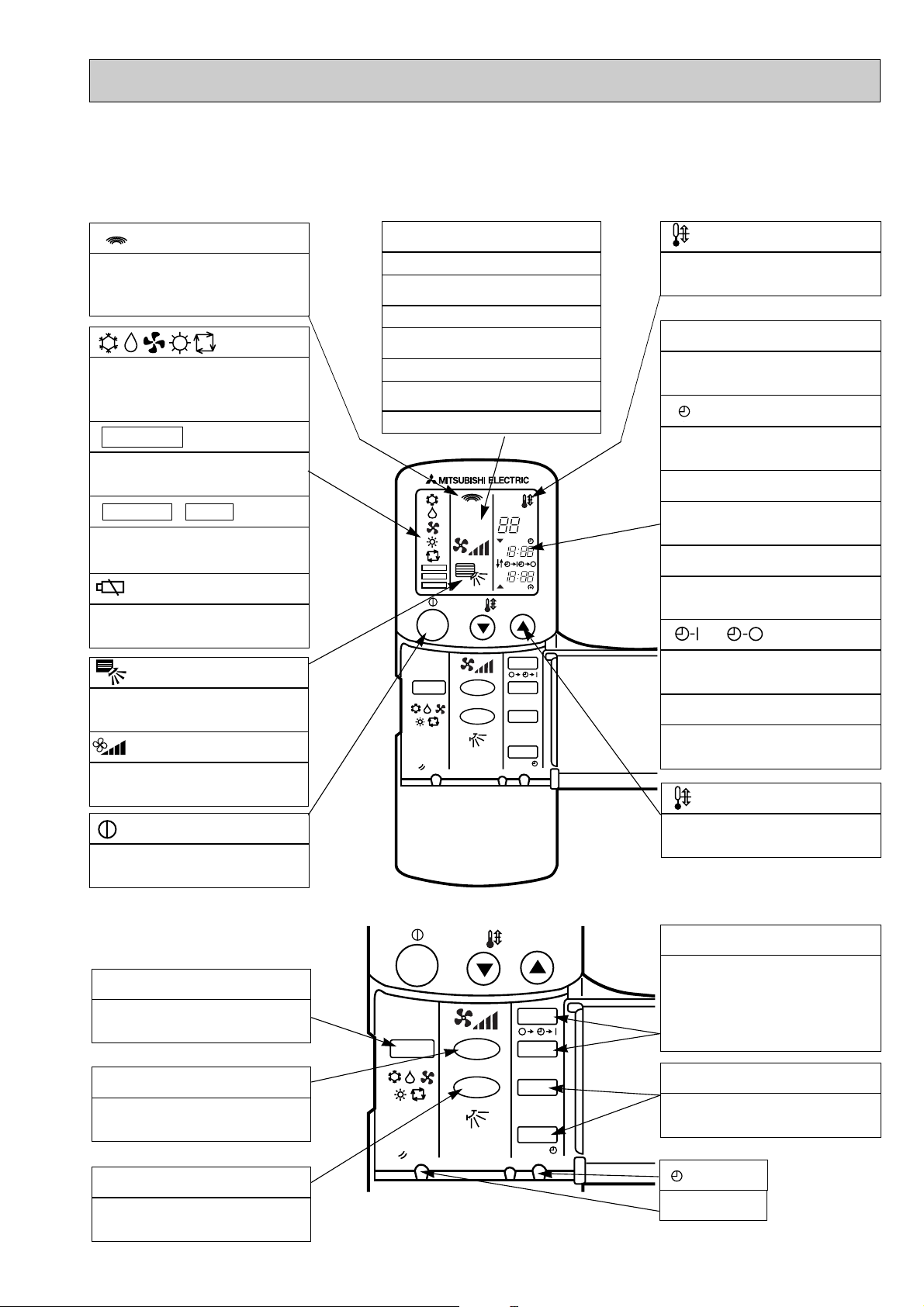
●Wireless remote controller
● When cover is open.
display
Lights up while transmission to the indoor unit
is mode using switches.
display
OPERATION MODE display
Operation mode display indicates which oper-
ation mode is in effect.
• FUNCTION
Lights up when function are set..
display
• TEST RUN • CHECK display
CHECK&TEST RUN display indicates that the
unit is being checked or test-run.
display
Displays when batteries are dead.
display
The vertical direction of airflow is indicated.
display
FAN SPEED display indicates which fan
speed has been selected.
ADDRESS display
Displays the refrigerant address.
UNIT NO. display
Displays the number of unit..
FUNCTION NO. display
Displays the mode.
SELECTION NO. display
Displays the selection number..
ADDRESS
UNIT No.
FUNCTION No.
SELECTION No.
FUNCTION
TEST RUN
CHECK
ON/OFF
MODE FAN
RESET
VANE
AM
PM
AM
PM
TEMP.
˚C
START
STOP
HR.
MIN.
display
SET TEMP. display indicates desired temperature set.
CLOCK display
DIsplays the current time.
“ ”display
Flashes when the current time is displayed.
TIMER display
Displays when in timer operation or when setting timer.
➡
“ ” “ ” display
➡
Displays the order of timer operation.
“ ” “ ” display
Displays whether timer is on or off.
▼
“ ” “ ” display
Displays when the current time and the timer
time can be changed.
▼
TEMP. button
display
The unit is turned ON and OFF alternately
each time the button is pressed.
● When cover is open.
MODE SELECT button
Used to switch the operation mode between
cooling , drying , blowing , heating and auto
mode.
FAN SPEED SELECT button
Used to change the fan speed.
VANE CONTROL button
Used to change the airflow direction.
ON/OFF
MODE FAN
RESET
5
VANE
TEMP.
START
STOP
HR.
MIN.
SET TEMPERATURE button sets any desired
room temperature.
TIMER CONTROL buttons
STOP (OFF timer): when this switch is set,
the air conditioner will be automatically
stopped at the preset time.
START(ON timer): when this switch is set, the
air conditioner will be automatically started at
the preset time.
HR. and MIN.buttons
Buttons used to set the “hour and minute” of
the current time and timer settings.
button
RESET button
Page 6

PKH-P2.5/3/4FALH2
ON/OFF TEMP
FAN
VANE
TEST RUN
AUTO STOP
AUTO START
h
min
LOUVER
MODE
CHECK
RESETSET CLOCK
MODEL SELECT
NOT AVAILABLE
CHECK
TEST RUN
˚C
AMPM
AMPM
VANE CONTROL button
Used to change the air flow direction.
CLOCK button
RESET button
SET button
ON/OFF button
The unit is turned ON and OFF alternately
each time the button is pressed.
LOUVER button
This switch the horizontal fan motion ON
and OFF.
(Not available for this model.)
MODE SELECT button
Used to switch the operation mode between
cooling, drying, blowing, heating and auto
mode.
CHECK-TEST RUN button
Only press this button to perform an inspection check or test operation.
Do not use it for normal operation.
FAN SPEED SELECT button
Used to change the fan speed.
TIMER display
Displays when in timer operation or when
setting timer.
button
SET TEMPERATURE button sets any desired
room temperature.
CLOCK display
Displays the current time.
“ ” “ ” display
Displays the order of timer operation.
“ ” “ ” display
Displays whether timer is on or off.
w In case the outdoor unit is cool only type,
the heating mode is not available.
Buttons used to set the “hour and minute” of
the current time and timer settings.
h and min buttons
display
SET TEMP. display indicates desired temperature set.
display
FAN SPEED display indicates which fan
speed has been selected.
display
The vertical direction of air flow is indicated.
display
Blinks when model is selected.
display
Lights up while transmission to the indoor
unit is mode using switches.
display
CHECK&TEST RUN display indicates that
the unit is being checked or test-run.
display
OPERATION MODE display
Operation mode display indicates which operation mode is in effect.
TIMER CONTROL buttons
AUTO STOP (OFF timer): when this switch
is set, the air conditioner will be automatically stopped at the preset time.
AUTO START (ON timer): when this switch
is set, the air conditioner will be automatically started at the preset time.
MODEL SELECT
CHECK
TEST RUN
PKA-P2.5/3/4FAL2
●Wireless remote controller
● When cover is open.
6
Page 7

5
Cooling
22,200
6,500
2.72
0.09
0.43
0.80
11.78 / 4.11
Heating
25,200(32,400)
7,400(9,500)
2.67(4.77)
0.09<2.10>
0.43<8.75>
0.80<8.75>
11.55 / 4.03
PKH-P2.5FALH / PKH-P2.5FALH
1
PKA-P2.5FAL / PKA-P2.5FAL1
Single phase, 50Hz, 220-230-240V
Munsell 3.4Y 7.7/0.8
Plate fin coil
Line flow (direct) x 2
0.040
15-20 (530-706)
0(direct blow)
<2.1>
Wireless remote controller & built-in
39-45
20(13/16)
1,400(13/16)
235(9-1/4)
340(13-3/8)
26(57)
24(53)
PUH-P2.5VGA, PUH-P2.5VGA1 / PUH-P2.5YGA, PUH-P2.5YGA1
Single phase, 50Hz, 220-230-240V / 3 phase, 50Hz, 380-400-415V(4wires)
77 / 32
Munsell 5Y 7/1
Linear Expansion Valve
Hermetic
NE41VMJM / NE41YEJM
1.9
Line start
Internal thermostat, HP switch, Discharge thermo. / Thermal relay, Discharge thermo, HP switch, Anti-phase protector.
38
Plate fin coil
Propeller (direct) x 1
0.070
50(1,770)
Reverse cycle
48
50
900(35-7/16)
330+20(13+3/4)
855 (33-5/8)
82(181)
R407C
3.3(7.3)
1.2 (Ester)MEL56
9.52 (3/8)
15.88 (5/8)
Flared
Flared
Max. 50m
Max. 50m
PKH-P2.5FALH / PKH-P2.5FALH
1
PKA-P2.5FAL / PKA-P2.5FAL1
Service Ref.
With Electric heater
Without Electric heater
With Electric heater
Without Electric heater
With Electric heater
Without Electric heater
Item
Btu/h
W
kW
kW
A
A
kW
K/min(CFM)
Pa(mmAq)
kW
dB
mm(in.)
mm(in.)
mm(in.)
mm(in.)
kg(lbs)
kg(lbs)
A
A
kW
W
kW
K
/min(CFM
)
dB
dB
mm(in.)
mm(in.)
mm(in.)
kg(lbs)
kg(lbs)
L
mm(in.)
mm(in.)
Function
Capacity w1
Total input w1
Service Ref.
Power supply(phase, cycle,voltage)
Input w2
Running current w2
Starting current w2
External finish
Heat exchanger
Fan Fan(drive) x No.
Fan motor output
Airflow(Low-High)
External static pressure
Booster heater w2
Operation control & Thermostat
Noise level(Low-High)
Unit drain pipe O.D.
Dimensions
Weight
Service Ref.
Power supply (phase, cycle, voltage)
Running current
Starting current
External finish
Refrigerant control
Compressor
Model
Motor output
Starter type
Protection devices
Crankcase heater
Heat exchanger
Fan Fan(drive) x No.
Fan motor output
Airflow
Defrost method
Noise level
Dimensions
Weight
Refrigerant
Charge
Oil (Model)
Pipe size O.D.
Connection method
Between the indoor &
outdoor unit
INDOOR UNITOUTDOOR UNIT
REFRIGERANT PIPING
W
D
H
Cooling
Heating
W
D
H
Liquid
Gas
Indoor side
Outdoor side
Height difference
Piping length
Notes1. Rating Conditions (ISO T1)
Cooling : Indoor : D.B. 27˚C(80˚F), W.B. 19˚C (66˚F) Outdoor : D.B. 35˚C(95˚F), W.B. 24˚C (75˚F)
Heating : Indoor : D.B. 20˚C(68˚F) Outdoor : D.B. 7˚C(45˚F), W.B. 6˚C (43˚F)
Refrigerant piping length (one way) : 5m (16ft)
3. Above data based on indicated voltage
Indoor Unit Single phase 240V 50Hz
Outdoor Unit Single phase 240V 50Hz / 3 phase 415V 50Hz
2. Guaranteed operating range
Upper limit
Lower limit
Upper limit
Lower limit
Indoor
D.B. 35˚C, W.B. 22.5˚C
D.B. 19˚C, W.B. 15˚C
D.B. 28˚C
D.B. 17˚C
Outdoor
D.B. 46˚C
D.B. -5˚C
D.B. 24˚C, W.B. 18˚C
D.B. -11˚C, W.B. -12˚C
Cooling
Heating
w1 : ( ) Shows the total rating.
w2 : < > Shows the only booster heater rating.
SPECIFICATIONS
1. Heat pump type
7
Page 8

Item
Function
Capacity w1
Total input w1
Service Ref.
Power supply(phase, cycle,voltage)
External finish
Heat exchanger
Fan Fan(drive) x No.
INDOOR UNITOUTDOOR UNIT
Booster heater w2
Operation control & Thermostat
Noise level(Low-High)
Unit drain pipe O.D.
Dimensions
Weight
Service Ref.
Power supply (phase, cycle, voltage)
External finish
Refrigerant control
Compressor
Crankcase heater
Heat exchanger
Fan Fan(drive) x No.
Defrost method
Noise level
Dimensions
Weight
Refrigerant
Pipe size O.D.
Connection method
Between the indoor &
REFRIGERANT PIPING
outdoor unit
Notes1. Rating Conditions (ISO T1)
2. Guaranteed operating range
3. Above data based on indicated voltage
Input w2
Running current w2
Starting current w2
Fan motor output
Airflow(Low-High)
External static pressure
Running current
Starting current
Model
Motor output
Starter type
Protection devices
Fan motor output
Airflow
Charge
Oil (Model)
Cooling : Indoor : D.B. 27˚C(80˚F), W.B. 19˚C (66˚F) Outdoor : D.B. 35˚C(95˚F), W.B. 24˚C (75˚F)
Heating : Indoor : D.B. 20˚C(68˚F) Outdoor : D.B. 7˚C(45˚F), W.B. 6˚C (43˚F)
Refrigerant piping length (one way) : 5m (16ft)
Cooling
Heating
Indoor Unit Single phase 240V 50Hz
Outdoor Unit Single phase 240V 50Hz / 3 phase 415V 50Hz
Service Ref.
With Electric heater
Without Electric heater
Upper limit
Lower limit
Upper limit
Lower limit
With Electric heater
Without Electric heater
Btu/h
W
With Electric heater
Without Electric heater
W
D
H
Cooling
Heating
W
D
H
Liquid
Gas
Indoor side
Outdoor side
Height difference
Piping length
Indoor
D.B. 35˚C, W.B. 22.5˚C
D.B. 19˚C, W.B. 15˚C
D.B. 28˚C
D.B. 17˚C
kW
kW
A
A
kW
K/min(CFM)
Pa(mmAq)
kW
dB
mm(in.)
mm(in.)
mm(in.)
mm(in.)
kg(lbs)
kg(lbs)
A
A
kW
W
kW
/min(CFM
K
dB
dB
mm(in.)
mm(in.)
mm(in.)
kg(lbs)
kg(lbs)
L
mm(in.)
mm(in.)
Cooling
Single phase, 50Hz, 220-230-240V / 3 phase, 50Hz, 380-400-415V(4wires)
14.64/5.46
Internal thermostat, HP switch, Discharge thermo. / Thermal relay, Discharge thermo, HP switch, Anti-phase protector.
)
Outdoor
D.B. 46˚C
D.B. -5˚C
D.B. 24˚C, W.B. 18˚C
D.B. -11˚C, W.B. -12˚C
PKH-P3FALH / PKH-P3FALH
PKA-P3FAL / PKA-P3FAL1
27,000
7,900
3.43
PKH-P3FALH / PKH-P3FALH
PKA-P3FAL / PKA-P3FAL1
Single phase, 50Hz, 220-230-240V
0.09
0.43
0.80
Munsell 3.4Y 7.7/0.8
Line flow (direct) x 2
15-20 (530-706)
0(direct blow)
Wireless remote controller & built-in
PUH-P3VGA / PUH-P3YGA
Munsell 5Y 7/1
Linear Expansion Valve
NE52VNJM / NE52YDJM
Propeller (direct) x 1
Reverse cycle
330+20(13+3/4)
1.6 (Ester)MEL56
w1 : ( ) Shows the total rating.
w2 : < > Shows the only booster heater rating.
1
Heating
32,200(39,400)
9,450(11,550)
3.61(5.71)
1
0.09<2.10>
0.43<8.75>
0.80<8.75>
Plate fin coil
0.040
<2.1>
39-45
20(13/16)
1,400(13/16)
235(9-1/4)
340(13-3/8)
26(57)
24(53)
15.43/5.76
93/41
Hermetic
2.5
Line start
38
Plate fin coil
0.070
50(1,770)
49
51
900(35-7/16)
855 (33-5/8)
82(181)
R407C
3.7(8.2)
9.52 (3/8)
15.88 (5/8)
Flared
Flared
Max. 50m
Max. 50m
8
Page 9

Item
Function
Capacity w1
Total input w1
Service Ref.
Power supply(phase, cycle,voltage)
External finish
Heat exchanger
Fan Fan(drive) x No.
INDOOR UNITOUTDOOR UNIT
Booster heater w2
Operation control & Thermostat
Noise level(Low-High)
Unit drain pipe O.D.
Dimensions
Weight
Service Ref.
Power supply (phase, cycle, voltage)
External finish
Refrigerant control
Compressor
Crankcase heater
Heat exchanger
Fan Fan(drive) x No.
Defrost method
Noise level
Dimensions
Weight
Refrigerant
Pipe size O.D.
Connection method
Between the indoor &
REFRIGERANT PIPING
outdoor unit
Notes1. Rating Conditions (ISO T1)
2. Guaranteed operating range
3. Above data based on indicated voltage
Input w2
Running current w2
Starting current w2
Fan motor output
Airflow(Low-High)
External static pressure
Running current
Starting current
Model
Motor output
Starter type
Protection devices
Fan motor output
Airflow
Charge
Oil (Model)
Cooling : Indoor : D.B. 27˚C(80˚F), W.B. 19˚C (66˚F) Outdoor : D.B. 35˚C(95˚F), W.B. 24˚C (75˚F)
Heating : Indoor : D.B. 20˚C(68˚F) Outdoor : D.B. 7˚C(45˚F), W.B. 6˚C (43˚F)
Refrigerant piping length (one way) : 5m (16ft)
Cooling
Heating
Indoor Unit Single phase 240V 50Hz
Outdoor Unit 3 phase 415V 50Hz
Service Ref.
With Electric heater
Without Electric heater
Upper limit
Lower limit
Upper limit
Lower limit
With Electric heater
Without Electric heater
Btu/h
W
With Electric heater
Without Electric heater
W
D
H
Cooling
Heating
W
D
H
Liquid
Gas
Indoor side
Outdoor side
Height difference
Piping length
Indoor
D.B. 35˚C, W.B. 22.5˚C
D.B. 19˚C, W.B. 15˚C
D.B. 28˚C
D.B. 17˚C
kW
kW
A
A
kW
K/min(CFM)
Pa(mmAq)
kW
dB
mm(in.)
mm(in.)
mm(in.)
mm(in.)
kg(lbs)
kg(lbs)
A
A
kW
W
kW
/min(CFM
K
dB
dB
mm(in.)
mm(in.)
mm(in.)
kg(lbs)
kg(lbs)
L
mm(in.)
mm(in.)
Cooling
33,100
Anti-phase protector, Thermal relay, Discharge thermo, HP switch
)
Outdoor
D.B. 46˚C
D.B. -5˚C
D.B. 24˚C, W.B. 18˚C
D.B. -11˚C, W.B. -12˚C
PKH-P4FALH / PKH-P4FALH
PKA-P4FAL / PKA-P4FAL1
9,700
3.47
PKH-P4FALH / PKH-P4FALH
PKA-P4FAL / PKA-P4FAL1
Single phase, 50Hz, 220-230-240V
0.11
0.52
0.90
Munsell 3.4Y 7.7/0.8
Plate fin coil
Line flow (direct) x 2
22-28(777-988)
0(direct blow)
Wireless remote controller & built-in
1,680(66-1/8)
PUH-P4YGA
3 phase, 50Hz, 380-400-415V (4wires)
5.49
Munsell 5Y 7/1
Linear Expansion Valve
NE56YDJM
Plate fin coil
Propeller (direct) x 2
0.070+0.070
Reverse cycle
900(35-7/16)
330+20(13+3/4)
1,260 (49-5/8)
1.6 (Ester)MEL56
w1 : ( ) Shows the total rating.
w2 : < > Shows the only booster heater rating.
1
Heating
37,200(45,400)
10,900(13,300)
3.65(6.05)
1
0.11<2.40>
0.52<10.00>
0.90<10.00>
0.070
<2.40>
41-46
20(13/16)
235(9-1/4)
340(13-3/8)
30(66)
28(62)
5.79
45
Hermetic
2.7
Line start
38
85(3,000)
51
53
96(212)
R407C
4.0(8.8)
9.52 (3/8)
19.05 (3/4)
Flared
Flared
Max. 50m
Max. 50m
9
Page 10

2. Cooling only type
Cooling
22,200
6,500
2.72
PKA-P2.5FAL / PKA-P2.5FAL1
Single phase, 50Hz, 220-230-240V
0.09
0.43
0.80
Munsell 3.4Y 7.7/0.8
Plate fin coil
Line flow (direct) x 2
0.040
15-20 (530-706)
0(direct blow)
—
Wireless remote controller & built-in
39-45
20(13/16)
1,400(13/16)
235(9-1/4)
340(13-3/8)
24(53)
PU-P2.5VGA / PU-P2.5VGA1
Single phase, 50Hz, 220-230-240V
11.78
77
Munsell 5Y 7/1
Linear Expansion Valve
Hermetic
NE41VMJM
1.9
Line start
Internal thermostat, HP switch, Discharge thermo.
38
Plate fin coil
Propeller (direct) x 1
0.070
50(1,770)
—
48
900(35-7/16)
330+20(13+3/4)
855 (33-5/8)
82(181)
R407C
3.3(7.3)
1.2 (Ester)MEL56
9.52 (3/8)
15.88 (5/8)
Flared
Flared
Max. 50m
Max. 50m
PKA-P2.5FAL / PKA-P2.5FAL
1
Service Ref.
Item
Btu/h
W
kW
kW
A
A
kW
K/min(CFM)
Pa(mmAq)
kW
dB
mm(in.)
mm(in.)
mm(in.)
mm(in.)
kg(lbs)
A
A
kW
W
kW
K
/min(CFM
)
dB
mm(in.)
mm(in.)
mm(in.)
kg(lbs)
kg(lbs)
L
mm(in.)
mm(in.)
Function
Capacity
Total input
Service Ref.
Power supply(phase, cycle,voltage)
Input
Running current
Starting current
External finish
Heat exchanger
Fan Fan(drive) x No.
Fan motor output
Airflow(Low-High)
External static pressure
Booster heater
Operation control & Thermostat
Noise level(Low-High)
Unit drain pipe O.D.
Dimensions
Weight
Service Ref.
Power supply (phase, cycle, voltage)
Running current
Starting current
External finish
Refrigerant control
Compressor
Model
Motor output
Starter type
Protection devices
Crankcase heater
Heat exchanger
Fan Fan(drive) x No.
Fan motor output
Airflow
Defrost method
Noise level
Dimensions
Weight
Refrigerant
Charge
Oil (Model)
Pipe size O.D.
Connection method
Between the indoor &
outdoor unit
INDOOR UNITOUTDOOR UNIT
REFRIGERANT PIPING
W
D
H
Cooling
W
D
H
Liquid
Gas
Indoor side
Outdoor side
Height difference
Piping length
Notes1. Rating Conditions (ISO T1)
Cooling : Indoor : D.B. 27˚C(80˚F), W.B. 19˚C (66˚F) Outdoor : D.B. 35˚C(95˚F), W.B. 24˚C (75˚F)
Refrigerant piping length (one way) : 5m (16ft)
3. Above data based on indicated voltage
Indoor Unit Single phase 240V 50Hz
Outdoor Unit Single phase 240V 50Hz
2. Guaranteed operating range
Upper limit
Lower limit
Indoor
D.B. 35˚C, W.B. 22.5˚C
D.B. 19˚C, W.B. 15˚C
Outdoor
D.B. 46˚C
D.B. -5˚C
Cooling
10
Page 11

W
D
H
W
D
H
Indoor
Service Ref.
Btu/h
W
kW
kW
A
A
kW
K/min(CFM)
Pa(mmAq)
kW
dB
mm(in.)
mm(in.)
mm(in.)
mm(in.)
kg(lbs)
A
A
kW
W
kW
/min(CFM
K
dB
mm(in.)
mm(in.)
mm(in.)
kg(lbs)
kg(lbs)
L
mm(in.)
mm(in.)
Single phase, 50Hz, 220-230-240V / 3 phase, 50Hz, 380-400-415V(4wires)
Internal thermostat, HP switch, Discharge thermo. / Thermal relay, Discharge thermo, HP switch, Anti-phase protector.
)
Outdoor
D.B. 46˚C
D.B. -5˚C
Item
Function
Capacity
Total input
Service Ref.
Power supply(phase, cycle,voltage)
External finish
Heat exchanger
Fan Fan(drive) x No.
INDOOR UNITOUTDOOR UNIT
Booster heater
Operation control & Thermostat
Noise level(Low-High)
Unit drain pipe O.D.
Dimensions
Weight
Service Ref.
Power supply (phase, cycle, voltage)
External finish
Refrigerant control
Compressor
Crankcase heater
Heat exchanger
Fan Fan(drive) x No.
Defrost method
Noise level
Weight
Refrigerant
Pipe size O.D.
Connection method
Between the indoor &
REFRIGERANT PIPING
outdoor unit
Notes1. Rating Conditions (ISO T1)
2. Guaranteed operating range
Input
Running current
Starting current
Fan motor output
Airflow(Low-High)
External static pressure
Running current
Starting current
Model
Motor output
Starter type
Protection devices
Fan motor output
Airflow
Dimensions
Charge
Oil (Model)
Cooling : Indoor : D.B. 27˚C(80˚F), W.B. 19˚C (66˚F) Outdoor : D.B. 35˚C(95˚F), W.B. 24˚C (75˚F)
Refrigerant piping length (one way) : 5m (16ft)
Cooling
Upper limit
Lower limit
Cooling
Liquid
Gas
Indoor side
Outdoor side
Height difference
Piping length
D.B. 35˚C, W.B. 22.5˚C
D.B. 19˚C, W.B. 15˚C
PKA-P3FAL / PKA-P3FAL
PKA-P3FAL / PKA-P3FAL1
Single phase, 50Hz, 220-230-240V
Munsell 3.4Y 7.7/0.8
Line flow (direct) x 2
15-20 (530-706)
0(direct blow)
Wireless remote controller & built-in
1,400(13/16)
PU-P3VGA / PU-P3YGA
Munsell 5Y 7/1
Linear Expansion Valve
NE52VNJM / NE52YDJM
Propeller (direct) x 1
900(35-7/16)
330+20(13+3/4)
1.6 (Ester)MEL56
1
Cooling
27,000
7,900
3.43
0.09
0.43
0.80
Plate fin coil
0.040
—
39-45
20(13/16)
235(9-1/4)
340(13-3/8)
24(53)
14.64/5.46
93/41
Hermetic
2.5
Line start
38
Plate fin coil
0.070
50(1,770)
—
49
855 (33-5/8)
82(181)
R407C
3.7(8.2)
9.52 (3/8)
15.88 (5/8)
Flared
Flared
Max. 50m
Max. 50m
3. Above data based on indicated voltage
Indoor Unit Single phase 240V 50Hz
Outdoor Unit Single phase 240V 50Hz / 3 phase 415V 50Hz
11
Page 12

W
D
H
W
D
H
Indoor
Service Ref.
Btu/h
W
kW
kW
A
A
kW
K/min(CFM)
Pa(mmAq)
kW
dB
mm(in.)
mm(in.)
mm(in.)
mm(in.)
kg(lbs)
A
A
kW
W
kW
/min(CFM
K
dB
mm(in.)
mm(in.)
mm(in.)
kg(lbs)
kg(lbs)
L
mm(in.)
mm(in.)
Anti-phase protector, Thermal relay, Discharge thermo, HP switch
)
Outdoor
D.B. 46˚C
D.B. -5˚C
Item
Function
Capacity
Total input
Service Ref.
Power supply(phase, cycle,voltage)
External finish
Heat exchanger
Fan Fan(drive) x No.
INDOOR UNITOUTDOOR UNIT
Booster heater
Operation control & Thermostat
Noise level(Low-High)
Unit drain pipe O.D.
Dimensions
Weight
Service Ref.
Power supply (phase, cycle, voltage)
External finish
Refrigerant control
Compressor
Crankcase heater
Heat exchanger
Fan Fan(drive) x No.
Defrost method
Noise level
Weight
Refrigerant
Pipe size O.D.
Connection method
Between the indoor &
REFRIGERANT PIPING
outdoor unit
Notes1. Rating Conditions (ISO T1)
2. Guaranteed operating range
Input
Running current
Starting current
Fan motor output
Airflow(Low-High)
External static pressure
Running current
Starting current
Model
Motor output
Starter type
Protection devices
Fan motor output
Airflow
Dimensions
Charge
Oil (Model)
Cooling : Indoor : D.B. 27˚C(80˚F), W.B. 19˚C (66˚F) Outdoor : D.B. 35˚C(95˚F), W.B. 24˚C (75˚F)
Refrigerant piping length (one way) : 5m (16ft)
Cooling
Upper limit
Lower limit
Cooling
Liquid
Gas
Indoor side
Outdoor side
Height difference
Piping length
D.B. 35˚C, W.B. 22.5˚C
D.B. 19˚C, W.B. 15˚C
PKA-P4FAL / PKA-P4FAL
PKA-P4FAL / PKA-P4FAL1
Single phase, 50Hz, 220-230-240V
Munsell 3.4Y 7.7/0.8
Line flow (direct) x 2
22-28(777-988)
0(direct blow)
Wireless remote controller & built-in
1,680(66-1/8)
3 phase, 50Hz, 380-400-415V (4wires)
Munsell 5Y 7/1
Linear Expansion Valve
Propeller (direct) x 2
330+20(13+3/4)
1,260 (49-5/8)
1.6 (Ester)MEL56
1
Cooling
33,100
9,700
3.47
0.11
0.52
0.90
Plate fin coil
0.070
—
41-46
20(13/16)
235(9-1/4)
340(13-3/8)
28(62)
PU-P4YGA
5.49
45
Hermetic
NE56YDJM
2.7
Line start
38
Plate fin coil
0.070+0.070
85(3,000)
—
51
900(35-7/16)
96(212)
R407C
4.0(8.8)
9.52 (3/8)
19.05 (3/4)
Flared
Flared
Max. 50m
Max. 50m
3. Above data based on indicated voltage
Indoor Unit Single phase 240V 50Hz
Outdoor Unit 3 phase 415V 50Hz
12
Page 13

3. Heat pump type
Item
Function
Capacity w1
Total input w1
Service Ref.
Power supply(phase, cycle,voltage)
External finish
Heat exchanger
Fan Fan(drive) x No.
INDOOR UNITOUTDOOR UNIT
Booster heater w2
Operation control & Thermostat
Noise level(Low-High)
Unit drain pipe O.D.
Dimensions
Weight
Service Ref.
Power supply (phase, cycle, voltage)
External finish
Refrigerant control
Compressor
Crankcase heater
Heat exchanger
Fan Fan(drive) x No.
Defrost method
Noise level
Dimensions
Weight
Refrigerant
Pipe size O.D.
Connection method
Between the indoor &
REFRIGERANT PIPING
outdoor unit
Notes1. Rating Conditions (ISO T1)
2. Guaranteed operating range
3. Above data based on indicated voltage
Input w2
Running current w2
Starting current w2
Fan motor output
Airflow(Low-High)
External static pressure
Running current
Starting current
Model
Motor output
Starter type
Protection devices
Fan motor output
Airflow
Charge
Oil (Model)
Cooling : Indoor : D.B. 27˚C(80˚F), W.B. 19˚C (66˚F) Outdoor : D.B. 35˚C(95˚F), W.B. 24˚C (75˚F)
Heating : Indoor : D.B. 20˚C(68˚F) Outdoor : D.B. 7˚C(45˚F), W.B. 6˚C (43˚F)
Refrigerant piping length (one way) : 5m (16ft)
Cooling
Heating
Indoor Unit Single phase 240V 50Hz
Outdoor Unit Single phase 240V 50Hz / 3 phase 415V 50Hz
Service Ref.
With Electric heater
Without Electric heater
Upper limit
Lower limit
Upper limit
Lower limit
With Electric heater
Without Electric heater
Btu/h
W
With Electric heater
Without Electric heater
W
D
H
Cooling
Heating
W
D
H
Liquid
Gas
Indoor side
Outdoor side
Height difference
Piping length
Indoor
D.B. 35˚C, W.B. 22.5˚C
D.B. 19˚C, W.B. 15˚C
D.B. 28˚C
D.B. 17˚C
kW
kW
A
A
kW
K/min(CFM)
Pa(mmAq)
kW
dB
mm(in.)
mm(in.)
mm(in.)
mm(in.)
kg(lbs)
kg(lbs)
A
A
kW
W
kW
/min(CFM
K
dB
dB
mm(in.)
mm(in.)
mm(in.)
kg(lbs)
kg(lbs)
L
mm(in.)
mm(in.)
Cooling
22,200
6,500
2.67
Single phase, 50Hz, 220-230-240V
0.09
0.43
0.80
Wireless remote controller & built-in
PUH-P2.5VGAA.UK / PUH-P2.5YGAA.UK
Single phase, 50Hz, 220-230-240V / 3 phase, 50Hz, 380-400-415V(4wires)
11.90 / 4.48
Internal thermostat, HP switch, Discharge thermo. / Thermal relay, Discharge thermo, HP switch.
)
Outdoor
D.B. 46˚C
D.B. -5˚C
D.B. 24˚C, W.B. 18˚C
D.B. -11˚C, W.B. -12˚C
PKH-P2.5FALH
PKA-P2.5FAL2
PKH-P2.5FALH
PKA-P2.5FAL2
Munsell 3.4Y 7.7/0.8
Line flow (direct) x 2
15-20 (530-706)
0(direct blow)
Munsell 5Y 7/1
Linear Expansion Valve
NE41VMJMT / NE41YEKMT
Propeller (direct) x 1
Reverse cycle
330+20(13+3/4)
1.2 (Ester)MEL56
w1 : ( ) Shows the total rating.
w2 : < > Shows the only booster heater rating.
2
Heating
25,200(32,400)
7,400(9,500)
2.67(4.43)
2
0.09<2.10>
0.43<8.75>
0.80<8.75>
Plate fin coil
0.040
<2.1>
39-45
20(13/16)
1,400(13/16)
235(9-1/4)
340(13-3/8)
26(57)
24(53)
11.51 / 4.34
77 / 35
Hermetic
1.9
Line start
38
Plate fin coil
0.070
50(1,770)
48
50
900(35-7/16)
855 (33-5/8)
82(181)
R407C
3.1(6.8)
9.52 (3/8)
15.88 (5/8)
Flared
Flared
Max. 50m
Max. 50m
13
Page 14

Item
Function
Capacity w1
Total input w1
Service Ref.
Power supply(phase, cycle,voltage)
External finish
Heat exchanger
Fan Fan(drive) x No.
INDOOR UNITOUTDOOR UNIT
Booster heater w2
Operation control & Thermostat
Noise level(Low-High)
Unit drain pipe O.D.
Dimensions
Weight
Service Ref.
Power supply (phase, cycle, voltage)
External finish
Refrigerant control
Compressor
Crankcase heater
Heat exchanger
Fan Fan(drive) x No.
Defrost method
Noise level
Dimensions
Weight
Refrigerant
Pipe size O.D.
Connection method
Between the indoor &
REFRIGERANT PIPING
outdoor unit
Notes1. Rating Conditions (ISO T1)
2. Guaranteed operating range
3. Above data based on indicated voltage
Input w2
Running current w2
Starting current w2
Fan motor output
Airflow(Low-High)
External static pressure
Running current
Starting current
Model
Motor output
Starter type
Protection devices
Fan motor output
Airflow
Charge
Oil (Model)
Cooling : Indoor : D.B. 27˚C(80˚F), W.B. 19˚C (66˚F) Outdoor : D.B. 35˚C(95˚F), W.B. 24˚C (75˚F)
Heating : Indoor : D.B. 20˚C(68˚F) Outdoor : D.B. 7˚C(45˚F), W.B. 6˚C (43˚F)
Refrigerant piping length (one way) : 5m (16ft)
Cooling
Heating
Indoor Unit Single phase 240V 50Hz
Outdoor Unit Single phase 240V 50Hz / 3 phase 415V 50Hz
Service Ref.
With Electric heater
Without Electric heater
Upper limit
Lower limit
Upper limit
Lower limit
With Electric heater
Without Electric heater
Btu/h
W
With Electric heater
Without Electric heater
W
D
H
Cooling
Heating
W
D
H
Liquid
Gas
Indoor side
Outdoor side
Height difference
Piping length
Indoor
D.B. 35˚C, W.B. 22.5˚C
D.B. 19˚C, W.B. 15˚C
D.B. 28˚C
D.B. 17˚C
kW
kW
A
A
kW
K/min(CFM)
Pa(mmAq)
kW
dB
mm(in.)
mm(in.)
mm(in.)
mm(in.)
kg(lbs)
kg(lbs)
A
A
kW
W
kW
/min(CFM
K
dB
dB
mm(in.)
mm(in.)
mm(in.)
kg(lbs)
kg(lbs)
L
mm(in.)
mm(in.)
Cooling
27,000
7,900
3.44
Single phase, 50Hz, 220-230-240V
0.09
0.43
0.80
Wireless remote controller & built-in
PUH-P3VGAA.UK / PUH-P3YGAA.UK
Single phase, 50Hz, 220-230-240V / 3 phase, 50Hz, 380-400-415V(4wires)
14.81 / 5.29
Internal thermostat, HP switch, Discharge thermo. / Thermal relay, Discharge thermo, HP switch.
)
Outdoor
D.B. 46˚C
D.B. -5˚C
D.B. 24˚C, W.B. 18˚C
D.B. -11˚C, W.B. -12˚C
PKH-P3FALH
PKA-P3FAL2
PKH-P3FALH
PKA-P3FAL2
Munsell 3.4Y 7.7/0.8
Line flow (direct) x 2
15-20 (530-706)
0(direct blow)
1,400(13/16)
Munsell 5Y 7/1
Linear Expansion Valve
NE52VNJMT / NE52YDKMT
Propeller (direct) x 1
Reverse cycle
900(35-7/16)
330+20(13+3/4)
1.3 (Ester)MEL56
w1 : ( ) Shows the total rating.
w2 : < > Shows the only booster heater rating.
2
Heating
32,200(39,400)
9,450(11,550)
3.62(5.72)
2
0.09<2.10>
0.43<8.75>
0.80<8.75>
Plate fin coil
0.040
<2.1>
39-45
20(13/16)
235(9-1/4)
340(13-3/8)
26(57)
24(53)
15.76 / 5.63
93 / 47
Hermetic
2.5
Line start
38
Plate fin coil
0.070
50(1,770)
49
51
855 (33-5/8)
82(181)
R407C
3.3(7.3)
9.52 (3/8)
15.88 (5/8)
Flared
Flared
Max. 50m
Max. 50m
14
Page 15

Item
Function
Capacity w1
Total input w1
Service Ref.
Power supply(phase, cycle,voltage)
External finish
Heat exchanger
Fan Fan(drive) x No.
INDOOR UNITOUTDOOR UNIT
Booster heater w2
Operation control & Thermostat
Noise level(Low-High)
Unit drain pipe O.D.
Dimensions
Weight
Service Ref.
Power supply (phase, cycle, voltage)
External finish
Refrigerant control
Compressor
Crankcase heater
Heat exchanger
Fan Fan(drive) x No.
Defrost method
Noise level
Dimensions
Weight
Refrigerant
Pipe size O.D.
Connection method
Between the indoor &
REFRIGERANT PIPING
outdoor unit
Notes1. Rating Conditions (ISO T1)
2. Guaranteed operating range
3. Above data based on indicated voltage
Input w2
Running current w2
Starting current w2
Fan motor output
Airflow(Low-High)
External static pressure
Running current
Starting current
Model
Motor output
Starter type
Protection devices
Fan motor output
Airflow
Charge
Oil (Model)
Cooling : Indoor : D.B. 27˚C(80˚F), W.B. 19˚C (66˚F) Outdoor : D.B. 35˚C(95˚F), W.B. 24˚C (75˚F)
Heating : Indoor : D.B. 20˚C(68˚F) Outdoor : D.B. 7˚C(45˚F), W.B. 6˚C (43˚F)
Refrigerant piping length (one way) : 5m (16ft)
Cooling
Heating
Indoor Unit Single phase 240V 50Hz
Outdoor Unit Single phase 240V 50Hz / 3 phase 415V 50Hz
Service Ref.
With Electric heater
Without Electric heater
Upper limit
Lower limit
Upper limit
Lower limit
With Electric heater
Without Electric heater
Btu/h
W
With Electric heater
Without Electric heater
W
D
H
Cooling
Heating
W
D
H
Liquid
Gas
Indoor side
Outdoor side
Height difference
Piping length
Indoor
D.B. 35˚C, W.B. 22.5˚C
D.B. 19˚C, W.B. 15˚C
D.B. 28˚C
D.B. 17˚C
kW
kW
A
A
kW
K/min(CFM)
Pa(mmAq)
kW
dB
mm(in.)
mm(in.)
mm(in.)
mm(in.)
kg(lbs)
kg(lbs)
A
A
kW
W
kW
/min(CFM
K
dB
dB
mm(in.)
mm(in.)
mm(in.)
kg(lbs)
kg(lbs)
L
mm(in.)
mm(in.)
Cooling
32,200
9,450
3.59
Single phase, 50Hz, 220-230-240V
0.11
0.52
0.90
Wireless remote controller & built-in
PUH-P4VGAA.UK / PUH-P4YGAA.UK
Single phase, 50Hz, 220-230-240V / 3 phase, 50Hz, 380-400-415V(4wires)
15.71 / 5.55
Internal thermostat, HP switch Discharge thermo. / Thermal relay, Discharge thermo, HP switch
)
Outdoor
D.B. 46˚C
D.B. -5˚C
D.B. 24˚C, W.B. 18˚C
D.B. -11˚C, W.B. -12˚C
PKH-P4FALH
PKA-P4FAL2
PKH-P4FALH
PKA-P4FAL2
Munsell 3.4Y 7.7/0.8
Plate fin coil
Line flow (direct) x 2
22-28(777-988)
0(direct blow)
1,680(66-1/8)
Munsell 5Y 7/1
Linear Expansion Valve
NE56VNJMT / NE56YDKMT
Plate fin coil
Propeller (direct) x 2
0.070+0.070
Reverse cycle
900(35-7/16)
330+20(13+3/4)
1,260 (49-5/8)
1.3 (Ester)MEL56
w1 : ( ) Shows the total rating.
w2 : < > Shows the only booster heater rating.
2
Heating
37,200(45,400)
10,900(13,300)
3.78(6.18)
2
0.11<2.40>
0.52<10.00>
0.90<10.00>
0.070
<2.40>
41-46
20(13/16)
235(9-1/4)
340(13-3/8)
30(66)
28(62)
16.58 / 5.86
99 / 49
Hermetic
2.7
Line start
38
85(3,000)
51
53
96(212)
R407C
4.0(8.8)
9.52 (3/8)
19.05 (3/4)
Flared
Flared
Max. 50m
Max. 50m
15
Page 16

4. Cooling only type
Cooling
22,200
6,500
2.67
PKA-P2.5FAL2
Single phase, 50Hz, 220-230-240V
0.09
0.43
0.80
Munsell 3.4Y 7.7/0.8
Plate fin coil
Line flow (direct) x 2
0.040
15-20 (530-706)
0(direct blow)
—
Wireless remote controller & built-in
39-45
20(13/16)
1,400(13/16)
235(9-1/4)
340(13-3/8)
24(53)
PU-P2.5VGAA.UK / PU-P2.5YGAA.UK
Single phase, 50Hz, 220-230-240V / 3 phase, 50Hz, 380-400-415V(4wires)
11.90 / 4.48
77 / 35
Munsell 5Y 7/1
Linear Expansion Valve
Hermetic
NE41VMJMT / NE41YEKMT
1.9
Line start
Internal thermostat, HP switch, Discharge thermo. / Thermal reray, HP switch, Discharge thermo.
38
Plate fin coil
Propeller (direct) x 1
0.070
50(1,770)
—
48
900(35-7/16)
330+20(13+3/4)
855 (33-5/8)
82(181)
R407C
3.1(6.8)
1.2 (Ester)MEL56
9.52 (3/8)
15.88 (5/8)
Flared
Flared
Max. 50m
Max. 50m
PKA-P2.5FAL
2
Service Ref.
Item
Btu/h
W
kW
kW
A
A
kW
K/min(CFM)
Pa(mmAq)
kW
dB
mm(in.)
mm(in.)
mm(in.)
mm(in.)
kg(lbs)
A
A
kW
W
kW
K
/min(CFM
)
dB
mm(in.)
mm(in.)
mm(in.)
kg(lbs)
kg(lbs)
L
mm(in.)
mm(in.)
Function
Capacity
Total input
Service Ref.
Power supply(phase, cycle,voltage)
Input
Running current
Starting current
External finish
Heat exchanger
Fan Fan(drive) x No.
Fan motor output
Airflow(Low-High)
External static pressure
Booster heater
Operation control & Thermostat
Noise level(Low-High)
Unit drain pipe O.D.
Dimensions
Weight
Service Ref.
Power supply (phase, cycle, voltage)
Running current
Starting current
External finish
Refrigerant control
Compressor
Model
Motor output
Starter type
Protection devices
Crankcase heater
Heat exchanger
Fan Fan(drive) x No.
Fan motor output
Airflow
Defrost method
Noise level
Dimensions
Weight
Refrigerant
Charge
Oil (Model)
Pipe size O.D.
Connection method
Between the indoor &
outdoor unit
INDOOR UNITOUTDOOR UNIT
REFRIGERANT PIPING
W
D
H
Cooling
W
D
H
Liquid
Gas
Indoor side
Outdoor side
Height difference
Piping length
Notes1. Rating Conditions (ISO T1)
Cooling : Indoor : D.B. 27˚C(80˚F), W.B. 19˚C (66˚F) Outdoor : D.B. 35˚C(95˚F), W.B. 24˚C (75˚F)
Refrigerant piping length (one way) : 5m (16ft)
3. Above data based on indicated voltage
Indoor Unit Single phase 240V 50Hz
Outdoor Unit Single phase 240V 50Hz / 3 phase 415V 50Hz
2. Guaranteed operating range
Upper limit
Lower limit
Indoor
D.B. 35˚C, W.B. 22.5˚C
D.B. 19˚C, W.B. 15˚C
Outdoor
D.B. 46˚C
D.B. -5˚C
Cooling
16
Page 17

W
D
H
W
D
H
Indoor
Service Ref.
Btu/h
W
kW
kW
A
A
kW
K/min(CFM)
Pa(mmAq)
kW
dB
mm(in.)
mm(in.)
mm(in.)
mm(in.)
kg(lbs)
A
A
kW
W
kW
/min(CFM
K
dB
mm(in.)
mm(in.)
mm(in.)
kg(lbs)
kg(lbs)
L
mm(in.)
mm(in.)
Single phase, 50Hz, 220-230-240V
Wireless remote controller & built-in
PU-P3VGAA.UK / PU-3YGAA.UK
Single phase, 50Hz, 220-230-240V / 3 phase, 50Hz, 380-400-415V(4wires)
Internal thermostat, HP switch, Discharge thermo. / Thermal relay, Discharge thermo, HP switch.
)
Outdoor
D.B. 46˚C
D.B. -5˚C
Item
Function
Capacity
Total input
Service Ref.
Power supply(phase, cycle,voltage)
External finish
Heat exchanger
Fan Fan(drive) x No.
INDOOR UNITOUTDOOR UNIT
Booster heater
Operation control & Thermostat
Noise level(Low-High)
Unit drain pipe O.D.
Dimensions
Weight
Service Ref.
Power supply (phase, cycle, voltage)
External finish
Refrigerant control
Compressor
Crankcase heater
Heat exchanger
Fan Fan(drive) x No.
Defrost method
Noise level
Weight
Refrigerant
Pipe size O.D.
Connection method
Between the indoor &
REFRIGERANT PIPING
outdoor unit
Notes1. Rating Conditions (ISO T1)
2. Guaranteed operating range
Input
Running current
Starting current
Fan motor output
Airflow(Low-High)
External static pressure
Running current
Starting current
Model
Motor output
Starter type
Protection devices
Fan motor output
Airflow
Dimensions
Charge
Oil (Model)
Cooling : Indoor : D.B. 27˚C(80˚F), W.B. 19˚C (66˚F) Outdoor : D.B. 35˚C(95˚F), W.B. 24˚C (75˚F)
Refrigerant piping length (one way) : 5m (16ft)
Cooling
Upper limit
Lower limit
Cooling
Liquid
Gas
Indoor side
Outdoor side
Height difference
Piping length
D.B. 35˚C, W.B. 22.5˚C
D.B. 19˚C, W.B. 15˚C
PKA-P3FAL
PKA-P3FAL2
Munsell 3.4Y 7.7/0.8
Plate fin coil
Line flow (direct) x 2
15-20 (530-706)
0(direct blow)
1,400(13/16)
Munsell 5Y 7/1
Linear Expansion Valve
NE52VNJMT / NE52YDKMT
Plate fin coil
Propeller (direct) x 1
900(35-7/16)
330+20(13+3/4)
855 (33-5/8)
1.3 (Ester)MEL56
2
Cooling
27,000
7,900
3.44
0.09
0.43
0.80
0.040
—
39-45
20(13/16)
235(9-1/4)
340(13-3/8)
24(53)
14.81 / 5.29
93 / 47
Hermetic
2.5
Line start
38
0.070
50(1,770)
—
49
82(181)
R407C
3.3(7.3)
9.52 (3/8)
15.88 (5/8)
Flared
Flared
Max. 50m
Max. 50m
3. Above data based on indicated voltage
Indoor Unit Single phase 240V 50Hz
Outdoor Unit Single phase 240V 50Hz / 3 phase 415V 50Hz
17
Page 18

W
D
H
W
D
H
Indoor
Service Ref.
Btu/h
W
kW
kW
A
A
kW
K/min(CFM)
Pa(mmAq)
kW
dB
mm(in.)
mm(in.)
mm(in.)
mm(in.)
kg(lbs)
A
A
kW
W
kW
/min(CFM
K
dB
mm(in.)
mm(in.)
mm(in.)
kg(lbs)
kg(lbs)
L
mm(in.)
mm(in.)
Single phase, 50Hz, 220-230-240V
Wireless remote controller & built-in
PU-P4VGAA.UK / PU-P4YGAA.UK
Single phase, 50Hz, 220-230-240V / 3 phase, 50Hz, 380-400-415V(4wires)
Internal thermostat, HP switch, Discharge thermo. / Thermal relay, Discharge thermo, HP switch
)
Outdoor
D.B. 46˚C
D.B. -5˚C
Item
Function
Capacity
Total input
Service Ref.
Power supply(phase, cycle,voltage)
External finish
Heat exchanger
Fan Fan(drive) x No.
INDOOR UNITOUTDOOR UNIT
Booster heater
Operation control & Thermostat
Noise level(Low-High)
Unit drain pipe O.D.
Dimensions
Weight
Service Ref.
Power supply (phase, cycle, voltage)
External finish
Refrigerant control
Compressor
Crankcase heater
Heat exchanger
Fan Fan(drive) x No.
Defrost method
Noise level
Weight
Refrigerant
Pipe size O.D.
Connection method
Between the indoor &
REFRIGERANT PIPING
outdoor unit
Notes1. Rating Conditions (ISO T1)
2. Guaranteed operating range
Input
Running current
Starting current
Fan motor output
Airflow(Low-High)
External static pressure
Running current
Starting current
Model
Motor output
Starter type
Protection devices
Fan motor output
Airflow
Dimensions
Charge
Oil (Model)
Cooling : Indoor : D.B. 27˚C(80˚F), W.B. 19˚C (66˚F) Outdoor : D.B. 35˚C(95˚F), W.B. 24˚C (75˚F)
Refrigerant piping length (one way) : 5m (16ft)
Cooling
Upper limit
Lower limit
Cooling
Liquid
Gas
Indoor side
Outdoor side
Height difference
Piping length
D.B. 35˚C, W.B. 22.5˚C
D.B. 19˚C, W.B. 15˚C
PKA-P4FAL
PKA-P4FAL2
Munsell 3.4Y 7.7/0.8
Line flow (direct) x 2
22-28(777-988)
0(direct blow)
1,680(66-1/8)
Munsell 5Y 7/1
Linear Expansion Valve
NE56VNJMT / NE56YDKMT
Propeller (direct) x 2
330+20(13+3/4)
1,260 (49-5/8)
1.3 (Ester)MEL56
2
Cooling
32,200
9,450
3.59
0.11
0.52
0.90
Plate fin coil
0.070
—
41-46
20(13/16)
235(9-1/4)
340(13-3/8)
28(62)
15.71 / 5.55
99 / 49
Hermetic
2.7
Line start
38
Plate fin coil
0.070+0.070
85(3,000)
—
51
900(35-7/16)
96(212)
R407C
4.0(8.8)
9.52 (3/8)
19.05 (3/4)
Flared
Flared
Max. 50m
Max. 50m
3. Above data based on indicated voltage
Indoor Unit Single phase 240V 50Hz
Outdoor Unit Single phase 240V 50Hz 3 phase 415V 50Hz
18
Page 19

6 DATA
Outdoor intake air D.B.(°C)
20 25 30
Indoor
Intake air
D.B.(°C)
Indoor
Intake air
W.B.(°C)
20
20
20
22
22
22
24
24
24
24
26
26
26
26
28
28
28
28
30
30
30
30
32
32
32
32
34
34
34
34
16
18
20
16
18
20
16
18
20
22
16
18
20
22
16
18
20
22
16
18
20
22
16
18
20
22
16
18
20
22
CA
6,435
6,890
7,410
6,435
6,890
7,410
6,435
6,890
7,410
7,898
6,435
6,890
7,410
7,898
6,435
6,890
7,410
7,898
6,435
6,890
7,410
7,898
6,435
6,890
7,410
7,898
6,435
6,890
7,410
7,898
SHC(W)
4,505
3,996
3,409
5,019
4,547
4,001
5,534
5,099
4,594
3,949
6,049
5,650
5,187
4,581
6,435
6,201
5,780
5,212
6,435
6,752
6,373
5,844
6,435
6,890
6,965
6,476
6,,435
6,890
7,410
7,108
SHF
0.70
0.58
0.46
0.78
0.66
0.54
0.86
0.74
0.62
0.50
0.94
0.82
0.70
0.58
1.00
0.90
0.78
0.66
1.00
0.98
0.86
0.74
1.00
1.00
0.94
0.82
1.00
1.00
1.00
0.90
SHF
0.70
0.58
0.46
0.78
0.66
0.54
0.86
0.74
0.62
0.50
0.94
0.82
0.70
0.58
1.00
0.90
0.78
0.66
1.00
0.98
0.86
0.74
1.00
1.00
0.94
0.82
1.00
1.00
1.00
0.90
SHF
0.70
0.58
0.46
0.78
0.66
0.54
0.86
0.74
0.62
0.50
0.94
0.82
0.70
0.58
1.00
0.90
0.78
0.66
1.00
0.98
0.86
0.74
1.00
1.00
0.94
0.82
1.00
1.00
1.00
0.90
P.C.
2.18
2.22
2.28
2.18
2.22
2.28
2.18
2.22
2.28
2.34
2.18
2.22
2.28
2.34
2.18
2.22
2.28
2.34
2.18
2.22
2.28
2.34
2.18
2.22
2.28
2.34
2.18
2.22
2.28
2.34
CA
6,240
6,695
7,248
6,240
6,695
7,248
6,240
6,695
7,248
7,735
6,240
6,695
7,248
7,735
6,240
6,695
7,248
7,735
6,240
6,695
7,248
7,735
6,240
6,695
7,248
7,735
6,240
6,695
7,248
7,735
SHC(W)
4,368
3,883
3,334
4,867
4,419
3,914
5,366
4,954
4,493
3,868
5,866
5,490
5,073
4,486
6,240
6,026
5,653
5,105
6,240
6,561
6,233
5,724
6,240
6,695
6,813
6,343
6,240
6,695
7,248
6,962
P.C.
2.30
2.34
2.39
2.30
2.34
2.39
2.30
2.34
2.39
2.48
2.30
2.34
2.39
2.48
2.30
2.34
2.39
2.48
2.30
2.34
2.39
2.48
2.30
2.34
2.39
2.48
2.30
2.34
2.39
2.48
CA
6,045
6,468
7,053
6,045
6,468
7,053
6,045
6,468
7,053
7,540
6,045
6,468
7,053
7,540
6,045
6,468
7,053
7,540
6,045
6,468
7,053
7,540
6,045
6,468
7,053
7,540
6,045
6,468
7,053
7,540
SHC(W)
4,232
3,751
3,244
4,715
4,269
3,808
5,199
4,786
4,373
3,770
5,682
5,303
4,937
4,373
6,045
5,821
5,501
4,976
6,045
6,338
6,065
5,580
6,045
6,468
6,629
6,183
6,045
6,468
7,053
6,786
P.C.
2.43
2.50
2.56
2.43
2.50
2.56
2.43
2.50
2.56
2.64
2.43
2.50
2.56
2.64
2.43
2.50
2.56
2.64
2.43
2.50
2.56
2.64
2.43
2.50
2.56
2.64
2.43
2.50
2.56
2.64
1. PERFORMANCE DATA
1) COOLING CAPACITY(1)
PKH-P2.5FALH, PKH-P2.5FALH1
PKA-P2.5FAL, PKA-P2.5FAL1
CA : Capacity (W) SHC(W) :Sensible heat capacity
P.C. : Power consumption (kW) SHF : Sensible heat factor
19
Page 20

COOLING CAPACITY(2)
Outdoor intake air D.B.(°C)
35 40 45
Indoor
Intake air
D.B.(°C)
Indoor
Intake air
W.B.(°C)
20
20
20
22
22
22
24
24
24
24
26
26
26
26
28
28
28
28
30
30
30
30
32
32
32
32
34
34
34
34
16
18
20
16
18
20
16
18
20
22
16
18
20
22
16
18
20
22
16
18
20
22
16
18
20
22
16
18
20
22
CA
5,785
6,240
6,760
5,785
6,240
6,760
5,785
6,240
6,760
7,280
5,785
6,240
6,760
7,280
5,785
6,240
6,760
7,280
5,785
6,240
6,760
7,280
5,785
6,240
6,760
7,280
5,785
6,240
6,760
7,280
SHC(W)
4,050
3,619
3,110
4,512
4,118
3,650
4,975
4,618
4,191
3,640
5,438
5,117
4,732
4,222
5,785
5,616
5,273
4,805
5,785
6,115
5,814
5,387
5,785
6,240
6,354
5,970
5,785
6,240
6,760
6,552
SHF
0.70
0.58
0.46
0.78
0.66
0.54
0.86
0.74
0.62
0.50
0.94
0.82
0.70
0.58
1.00
0.90
0.78
0.66
1.00
0.98
0.86
0.74
1.00
1.00
0.94
0.82
1.00
1.00
1.00
0.90
SHF
0.70
0.58
0.46
0.78
0.66
0.54
0.86
0.74
0.62
0.50
0.94
0.82
0.70
0.58
1.00
0.90
0.78
0.66
1.00
0.98
0.86
0.74
1.00
1.00
0.94
0.82
1.00
1.00
1.00
0.90
SHF
0.70
0.58
0.46
0.78
0.66
0.54
0.86
0.74
0.62
0.50
0.94
0.82
0.70
0.58
1.00
0.90
0.78
0.66
1.00
0.98
0.86
0.74
1.00
1.00
0.94
0.82
1.00
1.00
1.00
0.90
P.C.
2.61
2.68
2.75
2.61
2.68
2.75
2.61
2.68
2.75
2.80
2.61
2.68
2.75
2.80
2.61
2.68
2.75
2.80
2.61
2.68
2.75
2.80
2.61
2.68
2.75
2.80
2.61
2.68
2.75
2.80
CA
5,525
6,045
6,500
5,525
6,045
6,500
5,525
6,045
6,500
7,020
5,525
6,045
6,500
7,020
5,525
6,045
6,500
7,020
5,525
6,045
6,500
7,020
5,525
6,045
6,500
7,020
5,525
6,045
6,500
7,020
SHC(W)
3,868
3,506
2,990
4,310
3,990
3,510
4,752
4,473
4,030
3,510
5,194
4,957
4,550
4,072
5,525
5,441
5,070
4,633
5,525
5,924
5,590
5,195
5,525
6,045
6,110
5,756
5,525
6,045
6,500
6,318
P.C.
2.80
2.88
2.94
2.80
2.88
2.94
2.80
2.88
2.94
3.02
2.80
2.88
2.94
3.02
2.80
2.88
2.94
3.02
2.80
2.88
2.94
3.02
2.80
2.88
2.94
3.02
2.80
2.88
2.94
3.02
CA
5,265
5,655
6,110
5,265
5,655
6,110
5,265
5,655
6,110
6,630
5,265
5,655
6,110
6,630
5,265
5,655
6,110
6,630
5,265
5,655
6,110
6,630
5,265
5,655
6,110
6,630
5,265
5,655
6,110
6,630
SHC(W)
3,686
3,280
2,811
4,107
3,732
3,299
4,528
4,185
3,788
3,315
4,949
4,637
4,277
3,845
5,265
5,090
4,766
4,376
5,265
5,542
5,255
4,906
5,265
5,655
5,743
5,437
5,265
5,655
6,110
5,967
P.C.
3.03
3.10
3.16
3.03
3.10
3.16
3.03
3.10
3.16
3.21
3.03
3.10
3.16
3.21
3.03
3.10
3.16
3.21
3.03
3.10
3.16
3.21
3.03
3.10
3.16
3.21
3.03
3.10
3.16
3.21
PKH-P2.5FALH, PKH-P2.5FALH1
PKA-P2.5FAL, PKA-P2.5FAL1
CA : Capacity (W) SHC(W) :Sensible heat capacity
P.C. : Power consumption (kW) SHF : Sensible heat factor
20
Page 21

COOLING CAPACITY(3)
Outdoor intake air D.B.(°C)
20 25 30
Indoor
Intake air
D.B.(°C)
Indoor
Intake air
W.B.(°C)
20
20
20
22
22
22
24
24
24
24
26
26
26
26
28
28
28
28
30
30
30
30
32
32
32
32
34
34
34
34
16
18
20
16
18
20
16
18
20
22
16
18
20
22
16
18
20
22
16
18
20
22
16
18
20
22
16
18
20
22
CA
7,821
8,374
9,006
7,821
8,374
9,006
7,821
8,374
9,006
9,599
7,821
8,374
9,006
9,599
7,821
8,374
9,006
9,599
7,821
8,374
9,006
9,599
7,821
8,374
9,006
9,599
7,821
8,374
9,006
9,599
SHC(W)
5,005
4,354
3,602
5,631
5,024
4,323
6,257
5,694
5,043
4,223
6,882
6,364
5,764
4,991
7,508
7,034
6,484
5,759
7,821
7,704
7,205
6,527
7,821
8,374
7,925
7,295
7,821
8,374
8,646
8,063
SHF
0.64
0.52
0.40
0.72
0.60
0.48
0.80
0.68
0.56
0.44
0.88
0.76
0.64
0.52
0.96
0.84
0.72
0.60
1.00
0.92
0.80
0.68
1.00
1.00
0.88
0.76
1.00
1.00
0.96
0.84
SHF
0.64
0.52
0.40
0.72
0.60
0.48
0.80
0.68
0.56
0.44
0.88
0.76
0.64
0.52
0.96
0.84
0.72
0.60
1.00
0.92
0.80
0.68
1.00
1.00
0.88
0.76
1.00
1.00
0.96
0.84
SHF
0.64
0.52
0.40
0.72
0.60
0.48
0.80
0.68
0.56
0.44
0.88
0.76
0.64
0.52
0.96
0.84
0.72
0.60
1.00
0.92
0.80
0.68
1.00
1.00
0.88
0.76
1.00
1.00
0.96
0.84
P.C.
2.74
2.80
2.88
2.74
2.80
2.88
2.74
2.80
2.88
2.95
2.74
2.80
2.88
2.95
2.74
2.80
2.88
2.95
2.74
2.80
2.88
2.95
2.74
2.80
2.88
2.95
2.74
2.80
2.88
2.95
CA
7,584
8,137
8,809
7,584
8,137
8,809
7,584
8,137
8,809
9,401
7,584
8,137
8,809
9,401
7,584
8,137
8,809
9,401
7,584
8,137
8,809
9,401
7,584
8,137
8,809
9,401
7,584
8,137
8,809
9,401
SHC(W)
4,854
4,231
3,523
5,460
4,882
4,228
6,067
5,533
4,933
4,136
6,674
6,184
5,637
4,889
7,281
6,835
6,342
5,641
7,584
7,486
7,047
6,393
7,584
8,137
7,751
7,145
7,584
8,137
8,456
7,897
P.C.
2.90
2.95
3.02
2.90
2.95
3.02
2.90
2.95
3.02
3.12
2.90
2.95
3.02
3.12
2.90
2.95
3.02
3.12
2.90
2.95
3.02
3.12
2.90
2.95
3.02
3.12
2.90
2.95
3.02
3.12
CA
7,347
7,861
8,572
7,347
7,861
8,572
7,347
7,861
8,572
9,164
7,347
7,861
8,572
9,164
7,347
7,861
8,572
9,164
7,347
7,861
8,572
9,164
7,347
7,861
8,572
9,164
7,347
7,861
8,572
9,164
SHC(W)
4,702
4,087
3,429
5,290
4,716
4,114
5,878
5,345
4,800
4,032
6,465
5,974
5,486
4,765
7,053
6,603
6,171
5,498
7,347
7,232
6,857
6,232
7,347
7,861
7,543
6,965
7,347
7,861
8,229
7,698
P.C.
3.07
3.16
3.22
3.07
3.16
3.22
3.07
3.16
3.22
3.33
3.07
3.16
3.22
3.33
3.07
3.16
3.22
3.33
3.07
3.16
3.22
3.33
3.07
3.16
3.22
3.33
3.07
3.16
3.22
3.33
PKH-P3FALH, PKH-P3FALH1
PKA-P3FAL, PKA-P3FAL1
CA : Capacity (W) SHC(W) :Sensible heat capacity
P.C. : Power consumption (kW) SHF : Sensible heat factor
21
Page 22

COOLING CAPACITY(4)
Outdoor intake air D.B.(°C)
35 40 45
Indoor
Intake air
D.B.(°C)
Indoor
Intake air
W.B.(°C)
20
20
20
22
22
22
24
24
24
24
26
26
26
26
28
28
28
28
30
30
30
30
32
32
32
32
34
34
34
34
16
18
20
16
18
20
16
18
20
22
16
18
20
22
16
18
20
22
16
18
20
22
16
18
20
22
16
18
20
22
CA
7,031
7,584
8,216
7,031
7,584
8,216
7,031
7,584
8,216
8,848
7,031
7,584
8,216
8,848
7,031
7,584
8,216
8,848
7,031
7,584
8,216
8,848
7,031
7,584
8,216
8,848
7,031
7,584
8,216
8,848
SHC(W)
4,500
3,944
3,286
5,062
4,550
3,944
5,625
5,157
4,601
3,893
6,187
5,764
5,258
4,601
6,750
6,371
5,916
5,309
7,031
6,977
6,573
6,017
7,031
7,584
7,230
6,724
7,031
7,584
7,887
7,432
P.C.
3.29
3.38
3.46
3.29
3.38
3.46
3.29
3.38
3.46
3.53
3.29
3.38
3.46
3.53
3.29
3.38
3.46
3.53
3.29
3.38
3.46
3.53
3.29
3.38
3.46
3.53
3.29
3.38
3.46
3.53
CA
6,715
7,347
7,900
6,715
7,347
7,900
6,715
7,347
7,900
8,532
6,715
7,347
7,900
8,532
6,715
7,347
7,900
8,532
6,715
7,347
7,900
8,532
6,715
7,347
7,900
8,532
6,715
7,347
7,900
8,532
SHC(W)
4,298
3,820
3,160
4,835
4,408
3,792
5,372
4,996
4,424
3,754
5,909
5,584
5,056
4,437
6,446
6,171
5,688
5,119
6,715
6,759
6,320
5,802
6,715
7,347
6,952
6,484
6,715
7,347
7,584
7,167
P.C.
3.53
3.64
3.70
3.53
3.64
3.70
3.53
3.64
3.70
3.81
3.53
3.64
3.70
3.81
3.53
3.64
3.70
3.81
3.53
3.64
3.70
3.81
3.53
3.64
3.70
3.81
3.53
3.64
3.70
3.81
CA
6,399
6,873
7,426
6,399
6,873
7,426
6,399
6,873
7,426
8,058
6,399
6,873
7,426
8,058
6,399
6,873
7,426
8,058
6,399
6,873
7,426
8,058
6,399
6,873
7,426
8,058
6,399
6,873
7,426
8,058
SHC(W)
4,095
3,574
2,970
4,607
4,124
3,564
5,119
4,674
4,159
3,546
5,631
5,223
4,753
4,190
6,143
5,773
5,347
4,835
6,399
6,323
5,941
5,479
6,399
6,873
6,535
6,124
6,399
6,873
7,129
6,769
P.C.
3.82
3.91
3.98
3.82
3.91
3.98
3.82
3.91
3.98
4.05
3.82
3.91
3.98
4.05
3.82
3.91
3.98
4.05
3.82
3.91
3.98
4.05
3.82
3.91
3.98
4.05
3.82
3.91
3.98
4.05
SHF
0.64
0.52
0.40
0.72
0.60
0.48
0.80
0.68
0.56
0.44
0.88
0.76
0.64
0.52
0.96
0.84
0.72
0.60
1.00
0.92
0.80
0.68
1.00
1.00
0.88
0.76
1.00
1.00
0.96
0.84
SHF
0.64
0.52
0.40
0.72
0.60
0.48
0.80
0.68
0.56
0.44
0.88
0.76
0.64
0.52
0.96
0.84
0.72
0.60
1.00
0.92
0.80
0.68
1.00
1.00
0.88
0.76
1.00
1.00
0.96
0.84
SHF
0.64
0.52
0.40
0.72
0.60
0.48
0.80
0.68
0.56
0.44
0.88
0.76
0.64
0.52
0.96
0.84
0.72
0.60
1.00
0.92
0.80
0.68
1.00
1.00
0.88
0.76
1.00
1.00
0.96
0.84
PKH-P3FALH, PKH-P3FALH1
PKA-P3FAL, PKA-P3FAL1
CA : Capacity (W) SHC(W) :Sensible heat capacity
P.C. : Power consumption (kW) SHF : Sensible heat factor
22
Page 23

COOLING CAPACITY(5)
Outdoor intake air D.B.(°C)
20 25 30
Indoor
Intake air
D.B.(°C)
Indoor
Intake air
W.B.(°C)
20
20
20
22
22
22
24
24
24
24
26
26
26
26
28
28
28
28
30
30
30
30
32
32
32
32
34
34
34
34
16
18
20
16
18
20
16
18
20
22
16
18
20
22
16
18
20
22
16
18
20
22
16
18
20
22
16
18
20
22
CA
9,603
10,282
11,058
9,603
10,282
11,058
9,603
10,282
11,058
11,786
9,603
10,282
11,058
11,786
9,603
10,282
11,058
11,786
9,603
10,282
11,058
11,786
9,603
10,282
11,058
11,786
9,603
10,282
11,058
11,786
SHC(W)
6,338
5,552
4,644
7,106
6,375
5,529
7,874
7,197
6,414
5,421
8,643
8,020
7,298
6,364
9,411
8,843
8,183
7,307
9,603
9,665
9,068
8,250
9,603
10,282
9,952
9,193
9,603
10,282
10,837
10,136
SHF
0.66
0.54
0.42
0.74
0.62
0.50
0.82
0.70
0.58
0.46
0.90
0.78
0.66
0.54
0.98
0.86
0.74
0.62
1.00
0.94
0.82
0.70
1.00
1.00
0.90
0.78
1.00
1.00
0.98
0.86
SHF
0.66
0.54
0.42
0.74
0.62
0.50
0.82
0.70
0.58
0.46
0.90
0.78
0.66
0.54
0.98
0.86
0.74
0.62
1.00
0.94
0.82
0.70
1.00
1.00
0.90
0.78
1.00
1.00
0.98
0.86
SHF
0.66
0.54
0.42
0.74
0.62
0.50
0.82
0.70
0.58
0.46
0.90
0.78
0.66
0.54
0.98
0.86
0.74
0.62
1.00
0.94
0.82
0.70
1.00
1.00
0.90
0.78
1.00
1.00
0.98
0.86
P.C.
2.78
2.83
2.91
2.78
2.83
2.91
2.78
2.83
2.91
2.98
2.78
2.83
2.91
2.98
2.78
2.83
2.91
2.98
2.78
2.83
2.91
2.98
2.78
2.83
2.91
2.98
2.78
2.83
2.91
2.98
CA
9,312
9,991
10,816
9,312
9,991
10,816
9,312
9,991
10,816
11,543
9,312
9,991
10,816
11,543
9,312
9,991
10,816
11,543
9,312
9,991
10,816
11,543
9,312
9,991
10,816
11,543
9,312
9,991
10,816
11,543
SHC(W)
6,146
5,395
4,543
6,891
6,194
5,408
7,636
6,994
6,273
5,310
8,381
7,793
7,138
6,233
9,126
8,592
8,003
7,157
9,312
9,392
8,869
8,080
9,312
9,991
9,734
9,004
9,312
9,991
10,599
9,927
P.C.
2.93
2.98
3.05
2.93
2.98
3.05
2.93
2.98
3.05
3.16
2.93
2.98
3.05
3.16
2.93
2.98
3.05
3.16
2.93
2.98
3.05
3.16
2.93
2.98
3.05
3.16
2.93
2.98
3.05
3.16
CA
9,021
9,652
10,525
9,021
9,652
10,525
9,021
9,652
10,525
11,252
9,021
9,652
10,525
11,252
9,021
9,652
10,525
11,252
9,021
9,652
10,525
11,252
9,021
9,652
10,525
11,252
9,021
9,652
10,525
11,252
SHC(W)
5,954
5,212
4,420
6,676
5,984
5,262
7,397
6,756
6,104
5,176
8,119
7,528
6,946
6,076
8,841
8,300
7,788
6,976
9,021
9,072
8,630
7,876
9,021
9,652
9,472
8,777
9,021
9,652
10,314
9,677
P.C.
3.11
3.19
3.26
3.11
3.19
3.26
3.11
3.19
3.26
3.37
3.11
3.19
3.26
3.37
3.11
3.19
3.26
3.37
3.11
3.19
3.26
3.37
3.11
3.19
3.26
3.37
3.11
3.19
3.26
3.37
PKH-P4FALH, PKH-P4FALH1
PKA-P4FAL, PKA-P4FAL1
CA : Capacity (W) SHC(W) :Sensible heat capacity
P.C. : Power consumption (kW) SHF : Sensible heat factor
23
Page 24

COOLING CAPACITY(6)
Outdoor intake air D.B.(°C)
35 40 45
Indoor
Intake air
D.B.(°C)
Indoor
Intake air
W.B.(°C)
20
20
20
22
22
22
24
24
24
24
26
26
26
26
28
28
28
28
30
30
30
30
32
32
32
32
34
34
34
34
16
18
20
16
18
20
16
18
20
22
16
18
20
22
16
18
20
22
16
18
20
22
16
18
20
22
16
18
20
22
CA
8,633
9,312
10,088
8,633
9,312
10,088
8,633
9,312
10,088
10,864
8,633
9,312
10,088
10,864
8,633
9,312
10,088
10,864
8,633
9,312
10,088
10,864
8,633
9,312
10,088
10,864
8,633
9,312
10,088
10,864
SHC(W)
5,698
5,028
4,237
6,388
5,773
5,044
7,079
6,518
5,851
4,997
7,770
7,263
6,658
5,867
8,460
8,008
7,465
6,736
8,633
8,753
8,272
7,605
8,633
9,312
9,079
8,474
8,633
9,312
9,886
9,343
SHF
0.66
0.54
0.42
0.74
0.62
0.50
0.82
0.70
0.58
0.46
0.90
0.78
0.66
0.54
0.98
0.86
0.74
0.62
1.00
0.94
0.82
0.70
1.00
1.00
0.90
0.78
1.00
1.00
0.98
0.86
SHF
0.66
0.54
0.42
0.74
0.62
0.50
0.82
0.70
0.58
0.46
0.90
0.78
0.66
0.54
0.98
0.86
0.74
0.62
1.00
0.94
0.82
0.70
1.00
1.00
0.90
0.78
1.00
1.00
0.98
0.86
SHF
0.66
0.54
0.42
0.74
0.62
0.50
0.82
0.70
0.58
0.46
0.90
0.78
0.66
0.54
0.98
0.86
0.74
0.62
1.00
0.94
0.82
0.70
1.00
1.00
0.90
0.78
1.00
1.00
0.98
0.86
P.C.
3.33
3.42
3.50
3.33
3.42
3.50
3.33
3.42
3.50
3.57
3.33
3.42
3.50
3.57
3.33
3.42
3.50
3.57
3.33
3.42
3.50
3.57
3.33
3.42
3.50
3.57
3.33
3.42
3.50
3.57
CA
8,245
9,021
9,700
8,245
9,021
9,700
8,245
9,021
9,700
10,476
8,245
9,021
9,700
10,476
8,245
9,021
9,700
10,476
8,245
9,021
9,700
10,476
8,245
9,021
9,700
10,476
8,245
9,021
9,700
10,476
SHC(W)
5,442
4,871
4,074
6,101
5,593
4,850
6,761
6,315
5,626
4,819
7,421
7,036
6,402
5,657
8,080
7,758
7,178
6,495
8,245
8,480
7,954
7,333
8,245
9,021
8,730
8,171
8,245
9,021
9,506
9,009
P.C.
3.57
3.68
3.75
3.57
3.68
3.75
3.57
3.68
3.75
3.85
3.57
3.68
3.75
3.85
3.57
3.68
3.75
3.85
3.57
3.68
3.75
3.85
3.57
3.68
3.75
3.85
3.57
3.68
3.75
3.85
CA
7,857
8,439
9,118
7,857
8,439
9,118
7,857
8,439
9,118
9,894
7,857
8,439
9,118
9,894
7,857
8,439
9,118
9,894
7,857
8,439
9,118
9,894
7,857
8,439
9,118
9,894
7,857
8,439
9,118
9,894
SHC(W)
5,186
4,557
3,830
5,814
5,232
4,559
6,443
5,907
5,288
4,551
7,071
6,582
6,018
5,343
7,700
7,258
6,747
6,134
7,857
7,933
7,477
6,926
7,857
8,439
8,206
7,717
7,857
8,439
8,936
8,509
P.C.
3.87
3.96
4.03
3.87
3.96
4.03
3.87
3.96
4.03
4.09
3.87
3.96
4.03
4.09
3.87
3.96
4.03
4.09
3.87
3.96
4.03
4.09
3.87
3.96
4.03
4.09
3.87
3.96
4.03
4.09
PKH-P4FALH, PKH-P4FALH1
PKA-P4FAL, PKA-P4FAL1
CA : Capacity (W) SHC(W) :Sensible heat capacity
P.C. : Power consumption (kW) SHF : Sensible heat factor
24
Page 25

COOLING CAPACITY(7)
Outdoor intake air D.B.(°C)
20 25 30
Indoor
Intake air
D.B.(°C)
Indoor
Intake air
W.B.(°C)
20
20
20
22
22
22
24
24
24
26
26
26
28
28
28
30
30
30
32
32
32
34
34
34
16
18
20
16
18
20
16
18
20
16
18
20
16
18
20
16
18
20
16
18
20
16
18
20
CA
6,435
6,890
7,410
6,435
6,890
7,410
6,435
6,890
7,410
6,435
6,890
7,410
6,435
6,890
7,410
6,435
6,890
7,410
6,435
6,890
7,410
6,435
6,890
7,410
SHC(W)
4,505
3,996
3,409
5,019
4,547
4,001
5,534
5,099
4,594
6,049
5,650
5,187
6,435
6,201
5,780
6,435
6,752
6,373
6,435
6,890
6,965
6,435
6,890
7,410
SHF
0.70
0.58
0.46
0.78
0.66
0.54
0.86
0.74
0.62
0.94
0.82
0.70
1.00
0.90
0.78
1.00
0.98
0.86
1.00
1.00
0.94
1.00
1.00
1.00
SHF
0.70
0.58
0.46
0.78
0.66
0.54
0.86
0.74
0.62
0.94
0.82
0.70
1.00
0.90
0.78
1.00
0.98
0.86
1.00
1.00
0.94
1.00
1.00
1.00
SHF
0.70
0.58
0.46
0.78
0.66
0.54
0.86
0.74
0.62
0.94
0.82
0.70
1.00
0.90
0.78
1.00
0.98
0.86
1.00
1.00
0.94
1.00
1.00
1.00
P.C.
2.14
2.18
2.24
2.14
2.18
2.24
2.14
2.18
2.24
2.14
2.18
2.24
2.14
2.18
2.24
2.14
2.18
2.24
2.14
2.18
2.24
2.14
2.18
2.24
CA
6,240
6,695
7,248
6,240
6,695
7,248
6,240
6,695
7,248
6,240
6,695
7,248
6,240
6,695
7,248
6,240
6,695
7,248
6,240
6,695
7,248
6,240
6,695
7,248
SHC(W)
4,368
3,883
3,334
4,867
4,419
3,914
5,366
4,954
4,493
5,866
5,490
5,073
6,240
6,026
5,653
6,240
6,561
6,233
6,240
6,695
6,813
6,240
6,695
7,248
P.C.
2.26
2.30
2.35
2.26
2.30
2.35
2.26
2.30
2.35
2.26
2.30
2.35
2.26
2.30
2.35
2.26
2.30
2.35
2.26
2.30
2.35
2.26
2.30
2.35
CA
6,045
6,468
7,053
6,045
6,468
7,053
6,045
6,468
7,053
6,045
6,468
7,053
6,045
6,468
7,053
6,045
6,468
7,053
6,045
6,468
7,053
6,045
6,468
7,053
SHC(W)
4,232
3,751
3,244
4,715
4,269
3,808
5,199
4,786
4,373
5,682
5,303
4,937
6,045
5,821
5,501
6,045
6,338
6,065
6,045
6,468
6,629
6,045
6,468
7,053
P.C.
2.39
2.46
2.51
2.39
2.46
2.51
2.39
2.46
2.51
2.39
2.46
2.51
2.39
2.46
2.51
2.39
2.46
2.51
2.39
2.46
2.51
2.39
2.46
2.51
PKH-P2.5FALH2
PKA-P2.5FAL2
CA : Capacity (W) SHC(W) :Sensible heat capacity
P.C. : Power consumption (kW) SHF : Sensible heat factor
25
Page 26

Outdoor intake air D.B.(°C)
35 40 45
Indoor
Intake air
D.B.(°C)
Indoor
Intake air
W.B.(°C)
20
20
20
22
22
22
24
24
24
26
26
26
28
28
28
30
30
30
32
32
32
34
34
34
16
18
20
16
18
20
16
18
20
16
18
20
16
18
20
16
18
20
16
18
20
16
18
20
CA
5,785
6,240
6,760
5,785
6,240
6,760
5,785
6,240
6,760
5,785
6,240
6,760
5,785
6,240
6,760
5,785
6,240
6,760
5,785
6,240
6,760
5,785
6,240
6,760
SHC(W)
4,050
3,619
3,110
4,512
4,118
3,650
4,975
4,618
4,191
5,438
5,117
4,732
5,785
5,616
5,273
5,785
6,115
5,814
5,785
6,240
6,354
5,785
6,240
6,760
SHF
0.70
0.58
0.46
0.78
0.66
0.54
0.86
0.74
0.62
0.94
0.82
0.70
1.00
0.90
0.78
1.00
0.98
0.86
1.00
1.00
0.94
1.00
1.00
1.00
SHF
0.70
0.58
0.46
0.78
0.66
0.54
0.86
0.74
0.62
0.94
0.82
0.70
1.00
0.90
0.78
1.00
0.98
0.86
1.00
1.00
0.94
1.00
1.00
1.00
SHF
0.70
0.58
0.46
0.78
0.66
0.54
0.86
0.74
0.62
0.94
0.82
0.70
1.00
0.90
0.78
1.00
0.98
0.86
1.00
1.00
0.94
1.00
1.00
1.00
P.C.
2.56
2.63
2.70
2.56
2.63
2.70
2.56
2.63
2.70
2.56
2.63
2.70
2.56
2.63
2.70
2.56
2.63
2.70
2.56
2.63
2.70
2.56
2.63
2.70
CA
5,525
6,045
6,500
5,525
6,045
6,500
5,525
6,045
6,500
5,525
6,045
6,500
5,525
6,045
6,500
5,525
6,045
6,500
5,525
6,045
6,500
5,525
6,045
6,500
SHC(W)
3,868
3,506
2,990
4,310
3,990
3,510
4,752
4,473
4,030
5,194
4,957
4,550
5,525
5,441
5,070
5,525
5,924
5,590
5,525
6,045
6,110
5,525
6,045
6,500
P.C.
2.75
2.83
2.88
2.75
2.83
2.88
2.75
2.83
2.88
2.75
2.83
2.88
2.75
2.83
2.88
2.75
2.83
2.88
2.75
2.83
2.88
2.75
2.83
2.88
CA
5,265
5,655
6,110
5,265
5,655
6,110
5,265
5,655
6,110
5,265
5,655
6,110
5,265
5,655
6,110
5,265
5,655
6,110
5,265
5,655
6,110
5,265
5,655
6,110
SHC(W)
3,686
3,280
2,811
4,107
3,732
3,299
4,528
4,185
3,788
4,949
4,637
4,277
5,265
5,090
4,766
5,265
5,542
5,255
5,265
5,655
5,743
5,265
5,655
6,110
P.C.
2.98
3.04
3.10
2.98
3.04
3.10
2.98
3.04
3.10
2.98
3.04
3.10
2.98
3.04
3.10
2.98
3.04
3.10
2.98
3.04
3.10
2.98
3.04
3.10
COOLING CAPACITY(8)
PKH-P2.5FALH2
PKA-P2.5FAL2
CA : Capacity (W) SHC(W) :Sensible heat capacity
P.C. : Power consumption (kW) SHF : Sensible heat factor
26
Page 27

Outdoor intake air D.B.(°C)
20 25 30
Indoor
Intake air
D.B.(°C)
Indoor
Intake air
W.B.(°C)
20
20
20
22
22
22
24
24
24
26
26
26
28
28
28
30
30
30
32
32
32
34
34
34
16
18
20
16
18
20
16
18
20
16
18
20
16
18
20
16
18
20
16
18
20
16
18
20
CA
7,821
8,374
9,006
7,821
8,374
9,006
7,821
8,374
9,006
7,821
8,374
9,006
7,821
8,374
9,006
7,821
8,374
9,006
7,821
8,374
9,006
7,821
8,374
9,006
SHC(W)
5,005
4,354
3,602
5,631
5,024
4,323
6,257
5,694
5,043
6,882
6,364
5,764
7,508
7,034
6,484
7,821
7,704
7,205
7,821
8,374
7,925
7,821
8,374
8,646
SHF
0.64
0.52
0.40
0.72
0.60
0.48
0.80
0.68
0.56
0.88
0.76
0.64
0.96
0.84
0.72
1.00
0.92
0.80
1.00
1.00
0.88
1.00
1.00
0.96
SHF
0.64
0.52
0.40
0.72
0.60
0.48
0.80
0.68
0.56
0.88
0.76
0.64
0.96
0.84
0.72
1.00
0.92
0.80
1.00
1.00
0.88
1.00
1.00
0.96
SHF
0.64
0.52
0.40
0.72
0.60
0.48
0.80
0.68
0.56
0.88
0.76
0.64
0.96
0.84
0.72
1.00
0.92
0.80
1.00
1.00
0.88
1.00
1.00
0.96
P.C.
2.75
2.80
2.89
2.75
2.80
2.89
2.75
2.80
2.89
2.75
2.80
2.89
2.75
2.80
2.89
2.75
2.80
2.89
2.75
2.80
2.89
2.75
2.80
2.89
CA
7,584
8,137
8,809
7,584
8,137
8,809
7,584
8,137
8,809
7,584
8,137
8,809
7,584
8,137
8,809
7,584
8,137
8,809
7,584
8,137
8,809
7,584
8,137
8,809
SHC(W)
4,854
4,231
3,523
5,460
4,882
4,228
6,067
5,533
4,933
6,674
6,184
5,637
7,281
6,835
6,342
7,584
7,486
7,047
7,584
8,137
7,751
7,584
8,137
8,456
P.C.
2.91
2.96
3.03
2.91
2.96
3.03
2.91
2.96
3.03
2.91
2.96
3.03
2.91
2.96
3.03
2.91
2.96
3.03
2.91
2.96
3.03
2.91
2.96
3.03
CA
7,347
7,861
8,572
7,347
7,861
8,572
7,347
7,861
8,572
7,347
7,861
8,572
7,347
7,861
8,572
7,347
7,861
8,572
7,347
7,861
8,572
7,347
7,861
8,572
SHC(W)
4,702
4,087
3,429
5,290
4,716
4,114
5,878
5,345
4,800
6,465
5,974
5,486
7,053
6,603
6,171
7,347
7,232
6,857
7,347
7,861
7,543
7,347
7,861
8,229
P.C.
3.08
3.16
3.23
3.08
3.16
3.23
3.08
3.16
3.23
3.08
3.16
3.23
3.08
3.16
3.23
3.08
3.16
3.23
3.08
3.16
3.23
3.08
3.16
3.23
COOLING CAPACITY(9)
PKH-P3FALH2
PKA-P3FAL2
CA : Capacity (W) SHC(W) :Sensible heat capacity
P.C. : Power consumption (kW) SHF : Sensible heat factor
27
Page 28

Outdoor intake air D.B.(°C)
35 40 45
Indoor
Intake air
D.B.(°C)
Indoor
Intake air
W.B.(°C)
20
20
20
22
22
22
24
24
24
26
26
26
28
28
28
30
30
30
32
32
32
34
34
34
16
18
20
16
18
20
16
18
20
16
18
20
16
18
20
16
18
20
16
18
20
16
18
20
CA
7,031
7,584
8,216
7,031
7,584
8,216
7,031
7,584
8,216
7,031
7,584
8,216
7,031
7,584
8,216
7,031
7,584
8,216
7,031
7,584
8,216
7,031
7,584
8,216
SHC(W)
4,500
3,944
3,286
5,062
4,550
3,944
5,625
5,157
4,601
6,187
5,764
5,258
6,750
6,371
5,916
7,031
6,977
6,573
7,031
7,584
7,230
7,031
7,584
7,887
SHF
0.64
0.52
0.40
0.72
0.60
0.48
0.80
0.68
0.56
0.88
0.76
0.64
0.96
0.84
0.72
1.00
0.92
0.80
1.00
1.00
0.88
1.00
1.00
0.96
SHF
0.64
0.52
0.40
0.72
0.60
0.48
0.80
0.68
0.56
0.88
0.76
0.64
0.96
0.84
0.72
1.00
0.92
0.80
1.00
1.00
0.88
1.00
1.00
0.96
SHF
0.64
0.52
0.40
0.72
0.60
0.48
0.80
0.68
0.56
0.88
0.76
0.64
0.96
0.84
0.72
1.00
0.92
0.80
1.00
1.00
0.88
1.00
1.00
0.96
P.C.
3.30
3.39
3.47
3.30
3.39
3.47
3.30
3.39
3.47
3.30
3.39
3.47
3.30
3.39
3.47
3.30
3.39
3.47
3.30
3.39
3.47
3.30
3.39
3.47
CA
6,715
7,347
7,900
6,715
7,347
7,900
6,715
7,347
7,900
6,715
7,347
7,900
6,715
7,347
7,900
6,715
7,347
7,900
6,715
7,347
7,900
6,715
7,347
7,900
SHC(W)
4,298
3,820
3,160
4,835
4,408
3,792
5,372
4,996
4,424
5,909
5,584
5,056
6,446
6,171
5,688
6,715
6,759
6,320
6,715
7,347
6,952
6,715
7,347
7,584
P.C.
3.54
3.65
3.72
3.54
3.65
3.72
3.54
3.65
3.72
3.54
3.65
3.72
3.54
3.65
3.72
3.54
3.65
3.72
3.54
3.65
3.72
3.54
3.65
3.72
CA
6,399
6,873
7,426
6,399
6,873
7,426
6,399
6,873
7,426
6,399
6,873
7,426
6,399
6,873
7,426
6,399
6,873
7,426
6,399
6,873
7,426
6,399
6,873
7,426
SHC(W)
4,095
3,574
2,970
4,607
4,124
3,564
5,119
4,674
4,159
5,631
5,223
4,753
6,143
5,773
5,347
6,399
6,323
5,941
6,399
6,873
6,535
6,399
6,873
7,129
P.C.
3.84
3.92
3.99
3.84
3.92
3.99
3.84
3.92
3.99
3.84
3.92
3.99
3.84
3.92
3.99
3.84
3.92
3.99
3.84
3.92
3.99
3.84
3.92
3.99
COOLING CAPACITY(10)
PKH-P3FALH2
PKA-P3FAL2
CA : Capacity (W) SHC(W) :Sensible heat capacity
P.C. : Power consumption (kW) SHF : Sensible heat factor
28
Page 29

Outdoor intake air D.B.(°C)
20 25 30
Indoor
Intake air
D.B.(°C)
Indoor
Intake air
W.B.(°C)
20
20
20
22
22
22
24
24
24
26
26
26
28
28
28
30
30
30
32
32
32
34
34
34
16
18
20
16
18
20
16
18
20
16
18
20
16
18
20
16
18
20
16
18
20
16
18
20
CA
9,356
10,017
10,773
9,356
10,017
10,773
9,356
10,017
10,773
9,356
10,017
10,773
9,356
10,017
10,773
9,356
10,017
10,773
9,356
10,017
10,773
9,356
10,017
10,773
SHC(W)
6,175
5,409
4,525
6,923
6,211
5,387
7,672
7,012
6,248
8,420
7,813
7,110
9,168
8,615
7,972
9,356
9,416
8,834
9,356
10,017
9,696
9,356
10,017
10,558
SHF
0.66
0.54
0.42
0.74
0.62
0.50
0.82
0.70
0.58
0.90
0.78
0.66
0.98
0.86
0.74
1.00
0.94
0.82
1.00
1.00
0.90
1.00
1.00
0.98
SHF
0.66
0.54
0.42
0.74
0.62
0.50
0.82
0.70
0.58
0.90
0.78
0.66
0.98
0.86
0.74
1.00
0.94
0.82
1.00
1.00
0.90
1.00
1.00
0.98
SHF
0.66
0.54
0.42
0.74
0.62
0.50
0.82
0.70
0.58
0.90
0.78
0.66
0.98
0.86
0.74
1.00
0.94
0.82
1.00
1.00
0.90
1.00
1.00
0.98
P.C.
2.87
2.93
3.02
2.87
2.93
3.02
2.87
2.93
3.02
2.87
2.93
3.02
2.87
2.93
3.02
2.87
2.93
3.02
2.87
2.93
3.02
2.87
2.93
3.02
CA
9,072
9,734
10,537
9,072
9,734
10,537
9,072
9,734
10,537
9,072
9,734
10,537
9,072
9,734
10,537
9,072
9,734
10,537
9,072
9,734
10,537
9,072
9,734
10,537
SHC(W)
5,988
5,256
4,425
6,713
6,035
5,268
7,439
6,813
6,111
8,165
7,592
6,954
8,891
8,371
7,797
9,072
9,149
8,640
9,072
9,734
9,483
9,072
9,734
10,326
P.C.
3.03
3.09
3.16
3.03
3.09
3.16
3.03
3.09
3.16
3.03
3.09
3.16
3.03
3.09
3.16
3.03
3.09
3.16
3.03
3.09
3.16
3.03
3.09
3.16
CA
8,789
9,403
10,253
8,789
9,403
10,253
8,789
9,403
10,253
8,789
9,403
10,253
8,789
9,403
10,253
8,789
9,403
10,253
8,789
9,403
10,253
8,789
9,403
10,253
SHC(W)
5,800
5,077
4,306
6,503
5,830
5,127
7,207
6,582
5,947
7,910
7,334
6,767
8,613
8,086
7,587
8,789
8,839
8,408
8,789
9,403
9,228
8,789
9,403
10,048
P.C.
3.21
3.30
3.37
3.21
3.30
3.37
3.21
3.30
3.37
3.21
3.30
3.37
3.21
3.30
3.37
3.21
3.30
3.37
3.21
3.30
3.37
3.21
3.30
3.37
COOLING CAPACITY(11)
PKH-P4FALH2
PKA-P4FAL2
CA : Capacity (W) SHC(W) :Sensible heat capacity
P.C. : Power consumption (kW) SHF : Sensible heat factor
29
Page 30

Outdoor intake air D.B.(°C)
35 40 45
Indoor
Intake air
D.B.(°C)
Indoor
Intake air
W.B.(°C)
20
20
20
22
22
22
24
24
24
26
26
26
28
28
28
30
30
30
32
32
32
34
34
34
16
18
20
16
18
20
16
18
20
16
18
20
16
18
20
16
18
20
16
18
20
16
18
20
CA
8,411
9,072
9,828
8,411
9,072
9,828
8,411
9,072
9,828
8,411
9,072
9,828
8,411
9,072
9,828
8,411
9,072
9,828
8,411
9,072
9,828
8,411
9,072
9,828
SHC(W)
5,551
4,899
4,128
6,224
5,625
4,914
6,897
6,350
5,700
7,569
7,076
6,486
8,242
7,802
7,273
8,411
8,528
8,059
8,411
9,072
8,845
8,411
9,072
9,631
SHF
0.66
0.54
0.42
0.74
0.62
0.50
0.82
0.70
0.58
0.90
0.78
0.66
0.98
0.86
0.74
1.00
0.94
0.82
1.00
1.00
0.90
1.00
1.00
0.98
SHF
0.66
0.54
0.42
0.74
0.62
0.50
0.82
0.70
0.58
0.90
0.78
0.66
0.98
0.86
0.74
1.00
0.94
0.82
1.00
1.00
0.90
1.00
1.00
0.98
SHF
0.66
0.54
0.42
0.74
0.62
0.50
0.82
0.70
0.58
0.90
0.78
0.66
0.98
0.86
0.74
1.00
0.94
0.82
1.00
1.00
0.90
1.00
1.00
0.98
P.C.
3.45
3.54
3.63
3.45
3.54
3.63
3.45
3.54
3.63
3.45
3.54
3.63
3.45
3.54
3.63
3.45
3.54
3.63
3.45
3.54
3.63
3.45
3.54
3.63
CA
8,033
8,789
9,450
8,033
8,789
9,450
8,033
8,789
9,450
8,033
8,789
9,450
8,033
8,789
9,450
8,033
8,789
9,450
8,033
8,789
9,450
8,033
8,789
9,450
SHC(W)
5,301
4,746
3,969
5,944
5,449
4,725
6,587
6,152
5,481
7,229
6,855
6,237
7,872
7,558
6,993
8,033
8,261
7,749
8,033
8,789
8,505
8,033
8,789
9,261
P.C.
3.70
3.81
3.88
3.70
3.81
3.88
3.70
3.81
3.88
3.70
3.81
3.88
3.70
3.81
3.88
3.70
3.81
3.88
3.70
3.81
3.88
3.70
3.81
3.88
CA
7,655
8,222
8,883
7,655
8,222
8,883
7,655
8,222
8,883
7,655
8,222
8,883
7,655
8,222
8,883
7,655
8,222
8,883
7,655
8,222
8,883
7,655
8,222
8,883
SHC(W)
5,052
4,440
3,731
5,664
5,097
4,442
6,277
5,755
5,152
6,889
6,413
5,863
7,501
7,070
6,573
7,655
7,728
7,284
7,655
8,222
7,995
7,655
8,222
8,705
P.C.
4.00
4.09
4.16
4.00
4.09
4.16
4.00
4.09
4.16
4.00
4.09
4.16
4.00
4.09
4.16
4.00
4.09
4.16
4.00
4.09
4.16
4.00
4.09
4.16
COOLING CAPACITY(12)
PKH-P4FALH2
PKA-P4FAL2
CA : Capacity (W) SHC(W) :Sensible heat capacity
P.C. : Power consumption (kW) SHF : Sensible heat factor
30
Page 31

Capacity
P2.5
P3
P4
Refrigerant piping length(one way)
5m 10m 15m 20m 25m 30m 35m 40m 45m 50m
1.00
1.00
1.00
0.989
0.981
0.989
0.980
0.968
0.980
0.970
0.952
0.970
0.960
0.940
0.960
0.950
0.925
0.950
0.940
0.913
0.940
0.930
0.900
0.930
0.920
0.886
0.920
0.910
0.874
0.910
Cooling capacity correction factors
15
20
25
15
20
25
15
20
25
15
20
25
15
20
25
15
20
25
CA
4,699
4,514
4,366
6,001
5,765
5,576
6,922
6,649
6,431
4,699
4,514
4,366
5,017
4,819
4,661
6,922
6,649
6,431
P.C.
1.55
1.68
1.79
2.13
2.31
2.45
2.11
2.29
2.43
1.58
1.71
1.82
2.03
2.20
2.34
2.23
2.42
2.57
CA
5,106
4,884
4,736
6,521
6,237
6,048
7,521
7,194
6,976
5,106
4,884
4,736
5,451
5,214
5,056
7,521
7,194
6,976
P.C.
1.71
1.84
2.00
2.35
2.53
2.74
2.33
2.51
2.72
1.74
1.87
2.03
2.24
2.41
2.61
2.46
2.65
2.87
CA
5,698
5,402
5,180
7,277
6,899
6,615
8,393
7,957
7,630
5,698
5,402
5,180
6,083
5,767
5,530
8,393
7,957
7,630
P.C.
1.97
2.13
2.31
2.71
2.92
3.18
2.69
2.90
3.15
2.00
2.16
2.35
2.58
2.79
3.03
2.84
3.06
3.33
CA
7,474
7,215
6,808
9,545
9,214
8,694
11,009
10,628
10,028
7,474
7,215
6,808
7,979
7,703
7,268
11,009
10,628
10,028
P.C.
2.37
2.55
2.71
3.25
3.50
3.72
3.22
3.47
3.69
2.40
2.59
2.75
3.10
3.34
3.54
3.40
3.67
3.89
CA
8,436
8,140
7,844
10,773
10,395
10,017
12,426
11,990
11,554
8,436
8,140
7,844
9,006
8,690
8,374
12,426
11,990
11,554
P.C.
2.63
2.84
3.04
3.61
3.90
4.17
3.58
3.87
4.13
2.67
2.88
3.08
3.44
3.72
3.97
3.78
4.08
4.37
CA
9,398
9,065
8,732
12,002
11,576
11,151
13,843
13,353
12,862
9,398
9,065
8,732
10,033
9,678
9,322
13,843
13,353
12,862
P.C.
2.84
3.05
3.27
3.90
4.19
4.49
3.87
4.15
4.46
2.88
3.10
3.32
3.72
3.99
4.28
4.08
4.38
4.71
-10 -5 0Service Ref.
Indoor
intake
air
W.B.(˚C)
PKH-P2.5FALH
PKA-P2.5FAL
PKH-P2.5FALH
1
PKA-P2.5FAL1
PKH-P3FALH
PKA-P3FAL
PKH-P3FALH
1
PKA-P3FAL1
PKH-P4FALH
PKA-P4FAL
PKH-P4FALH
1
PKA-P4FAL1
PKH-P2.5FALH
2
PKA-P2.5FAL2
PKH-P3FALH2
PKA-P3FAL2
PKH-P4FALH2
PKA-P4FAL2
5
Outdoor intake air D.B.(˚C)
10 15
Capacity
P2.5
P3
P4
Refrigerant piping length(one way)
5m 10m 15m 20m 25m 30m 35m 40m 45m 50m
1.00
1.00
1.00
0.998
0.998
0.998
0.995
0.995
0.995
0.993
0.993
0.993
0.990
0.990
0.990
0.988
0.988
0.988
0.985
0.985
0.985
0.983
0.983
0.983
0.980
0.980
0.980
0.978
0.978
0.978
2) HEATING CAPACITY
Note CA : Capacity (W)
Heating capacity correction factors
P.C. : Power consumption (kW)
31
Page 32

2. PERFORMANCE CURVE
OUTDOOR D.B.(°C)
TOTAL INPUT (RATIO) CAPACITY (RATIO)
INDOOR
W.B.(°C)
INDOOR
W.B.(°C)
1.4
1.2
1.0
0.8
10
22
20
18
16
22
20
18
16
20 30 46400-5
1.2
1.0
0.8
0.6
0.4
OUTDOOR W.B.(°C)
INDOOR
D.B.(°C)
INDOOR
D.B.(°C)
TOTAL INPUT (RATIO) CAPACITY (RATIO)
1.4
1.2
1.0
15
20
25
25
20
15
0.8
0.6
0.4
1.4
1.2
1.0
0.8
0.6
0.4
-12 -10 -5 0 5 10 15
Correcting the capacity line influenced by frosting.
Not correcting the capacity line influenced by frosting.
HeatingCooling
32
Page 33

Service
Ref.
Indoor unit
Outdoor unit
Mode
Capacity (W)
Total Input (kW)
Input (kW)
Current (A)
Current (A)
Starting current (A)
Indoor
unit
Outdoor unit
With heater
Without heater
PKH-P2.5FALH
PKH-P2.5FALH1
PKA-P2.5FAL
PKA-P2.5FAL1
PUH-P2.5VGA
PUH-P2.5VGA1
PUH-P2.5YGA
PUH-P2.5YGA1
PKH-P4FALH
PKH-P4FALH1
PKA-P4FAL
PKA-P4FAL1
PUH-P4YGA
PKH-P3FALH
PKH-P3FALH
1
PKA-P3FAL
PKA-P3FAL1
PUH-P3VGA PUH-P3YGA
w ( ) Shows the total rating.
< > Shows the only booster heater rating.
(In+Out)
(In+Out+Heater)
Cool
6,450
2.70
0.09
0.43
11.82
74
Cool
6,450
2.70
0.09
0.43
4.19
31
Heat
7,350
(9,280)
2.63
(4.56)
0.09
<1.93>
0.43
<8.39>
11.50
74
Heat
7,350
(9,280)
2.63
(4.56)
0.09
<1.93>
0.43
<8.39>
4.07
31
Cool
9,600
3.46
0.11
0.52
5.48
43
Heat
10,800
(13,000)
3.64
(5.84)
0.11
<2.20>
0.52
<9.57>
5.78
43
Cool
7,850
3.42
0.09
0.43
15.08
89
Heat
9,400
(11,330)
3.60
(5.53)
0.09
<1.93>
0.43
<8.39>
15.89
89
Cool
7,850
3.42
0.09
0.43
5.46
40
Heat
9,400
(11,330)
3.60
(5.53)
0.09
<1.93>
0.43
<8.39>
5.75
40
Service
Ref.
Indoor unit
Outdoor unit
Mode
Capacity (W)
Total Input (kW)
Input (kW)
Current (A)
Current (A)
Starting current (A)
Indoor
unit
Outdoor unit
With heater
Without heater
PKH-P2.5FALH
PKH-P2.5FALH1
PKA-P2.5FAL
PKA-P2.5FAL1
PUH-P2.5VGA
PUH-P2.5VGA1
PUH-P2.5YGA
PUH-P2.5YGA1
PKH-P4FALH
PKH-P4FALH1
PKA-P4FAL
PKA-P4FAL1
PUH-P4YGA
PKH-P3FALH
PKH-P3FALH
1
PKA-P3FAL
PKA-P3FAL1
PUH-P3VGA PUH-P3YGA
w ( ) Shows the total rating.
< > Shows the only booster heater rating.
(In+Out)
(In+Out+Heater)
Cool
6,500
2.72
0.09
0.43
11.78
77
Cool
6,500
2.72
0.09
0.43
4.11
32
Heat
7,400
(9,500)
2.67
(4.77)
0.09
<2.10>
0.43
<8.75>
11.55
77
Heat
7,400
(9,500)
2.67
(4.77)
0.09
<2.10>
0.43
<8.75>
4.03
32
Cool
9,700
3.47
0.11
0.52
5.49
45
Heat
10,900
(13,300)
3.65
(6.05)
0.11
<2.40>
0.52
<10.00>
5.79
45
Cool
7,900
3.43
0.09
0.43
14.64
93
Heat
9,450
(11,550)
3.61
(5.71)
0.09
<2.10>
0.43
<8.75>
15.43
93
Cool
7,900
3.43
0.09
0.43
5.46
41
Heat
9,450
(11,550)
3.61
(5.71)
0.09
<2.10>
0.43
<8.75>
5.76
41
3. ELECTRICAL DATA
Service
Ref.
Indoor unit
Outdoor unit
Mode
Capacity (W)
Total Input (kW)
Input (kW)
Current (A)
Current (A)
Starting current (A)
Indoor
unit
Outdoor unit
With heater
Without heater
PKH-P2.5FALH
PKH-P2.5FALH1
PKA-P2.5FAL
PKA-P2.5FAL1
PUH-P2.5VGA
PUH-P2.5VGA1
PUH-P2.5YGA
PUH-P2.5YGA1
PKH-P4FALH
PKH-P4FALH1
PKA-P4FAL
PKA-P4FAL1
PUH-P4YGA
Cool
6,400
2.67
0.09
0.43
11.96
70
Cool
6,400
2.67
0.09
0.43
4.31
29
Heat
7,300
(9,060)
2.58
(4.34)
0.09
<1.76>
0.43
<8.00>
11.54
70
Heat
7,300
(9,060)
2.58
(4.34)
0.09
<1.76>
0.43
<8.00>
4.16
29
Cool
9,500
3.44
0.11
0.52
5.55
41
Heat
10,700
(12,720)
3.62
(5.64)
0.11
<2.02>
0.52
<9.18>
5.86
41
PKH-P3FALH
PKH-P3FALH
1
PKA-P3FAL
PKA-P3FAL1
PUH-P3VGA
Cool
7,800
3.41
0.09
0.43
15.55
84
Heat
9,350
(11,110)
3.59
(5.35)
0.09
<1.76>
0.43
<8.00>
16.40
84
PUH-P3YGA
Cool
7,800
3.41
0.09
0.43
5.54
38
Heat
9,350
(11,110)
3.59
(5.35)
0.09
<1.76>
0.43
<8.00>
5.84
38
w ( ) Shows the total rating.
< > Shows the only booster heater rating.
(In+Out)
(In+Out+Heater)
3.1. Heat pump type
Indoor unit …220V 50Hz Single phase Outdoor unit…220V 50Hz Single phase / 380V 50Hz 3phase
Indoor unit …230V 50Hz Single phase Outdoor unit…230V 50Hz Single phase / 400V 50Hz 3phase
Indoor unit …240V 50Hz Single phase Outdoor unit…240V 50Hz Single phase / 415V 50Hz 3phase
33
Page 34

3.2. Cooling only type
Service Ref.
Indoor unit
Outdoor unit
Mode
Capacity (W)
Total Input (kW) (In + Out)
Input (kW)
Current (A)
Current (A)
Starting current (A)
Indoor unit
Outdoor unit
PKA-P2.5FAL
PKA-P2.5FAL
1
PU-P2.5VGA
PU-P2.5VGA
1
PKA-P3FAL
PKA-P3FAL
1
PU-P3VGA PU-P3YGA
Cool
6,400
2.67
0.09
0.43
11.96
70
Cool
7,800
3.41
0.09
0.43
15.55
84
Cool
7,800
3.41
0.09
0.43
5.54
38
PKA-P4FAL
PKA-P4FAL
1
PU-P4YGA
Cool
9,500
3.44
0.11
0.52
5.55
41
Service Ref.
Indoor unit
Outdoor unit
Mode
Capacity (W)
Total Input (kW) (In + Out)
Input (kW)
Current (A)
Current (A)
Starting current (A)
Indoor unit
Outdoor unit
PKA-P2.5FAL
PKA-P2.5FAL
1
PU-P2.5VGA
PU-P2.5VGA
1
PKA-P3FAL
PKA-P3FAL
1
PU-P3VGA PU-P3YGA
PKA-P4FAL
PKA-P4FAL
1
PU-P4YGA
Cool
6,450
2.70
0.09
0.43
11.82
74
Cool
7,850
3.42
0.09
0.43
15.08
89
Cool
7,850
3.42
0.09
0.43
5.46
40
Cool
9,600
3.46
0.11
0.52
5.48
43
Service Ref.
Indoor unit
Outdoor unit
Mode
Capacity (W)
Total Input (kW) (In + Out)
Input (kW)
Current (A)
Current (A)
Starting current (A)
Indoor unit
Outdoor unit
PKA-P2.5FAL
PKA-P2.5FAL
1
PU-P2.5VGA
PU-P2.5VGA
1
PKA-P3FAL
PKA-P3FAL
1
PU-P3VGA PU-P3YGA
PKA-P4FAL
PKA-P4FAL
1
PU-P4YGA
Cool
6,500
2.72
0.09
0.43
11.78
77
Cool
7,900
3.43
0.09
0.43
14.64
93
Cool
7,900
3.43
0.09
0.43
5.46
41
Cool
9,700
3.47
0.11
0.52
5.49
45
Indoor unit …220V 50Hz Single phase
Outdoor unit…220V 50Hz Single phase / 380V 50Hz 3phase
Indoor unit …230V 50Hz Single phase
Outdoor unit…230V 50Hz Single phase / 400V 50Hz 3phase
Indoor unit …240V 50Hz Single phase
Outdoor unit…240V 50Hz Single phase / 415V 50Hz 3phase
34
Page 35

3.3. Heat pump type
Model
Indoor unit
Outdoor unit
Mode
Capacity (W)
Total Input (kW)
Input (kW)
Current (A)
Starting current (A)
Current (A)
Indoor unit
Outdoor unit
PKH-P2.5FALH2
PKA-P2.5FAL2
PKH-P4FALH2
PKA-P4FAL2
PUH-P4YGAA.UK
Cool
6,400
2.62
0.09
0.43
71
12.98
Cool
6,400
2.62
0.09
0.43
32
4.89
Heat
7,300
(9,060)
2.58
(4.34)
0.09
<1.76>
0.43
<8.00>
71
12.56
Heat
7,300
(9,060)
2.58
(4.34)
0.09
<1.76>
0.43
<8.00>
32
4.73
Cool
9,350
3.56
0.11
0.52
91
17.13
Heat
10,700
(12,720)
3.75
(5.77)
0.11
<2.02>
0.52
<9.18>
91
18.08
PUH-P4YGAA.UK
Cool
9,350
3.56
0.11
0.52
44
6.06
Heat
10,700
(12,720)
3.75
(5.77)
0.11
<2.02>
0.52
<9.18>
44
6.40
PKH-P3FALH
2
PKA-P3FAL2
PUH-P3VGAA.UK
PUH-P2.5VGAA.UK PUH-P2.5YGAA.UK
Cool
7,800
3.42
0.09
0.43
85
16.16
Heat
9,350
(11,110)
3.60
(5.36)
0.09
<1.76>
0.43
<8.00>
85
17.19
PUH-P3YGAA.UK
Cool
7,800
3.42
0.09
0.43
43
5.78
Heat
9,350
(11,110)
3.60
(5.36)
0.09
<1.76>
0.43
<8.00>
43
6.15
w ( ) Shows the total rating.
< > Shows the only booster heater rating.
(In+Out)
(In+Out+Heater)
Indoor unit …220V 50Hz Single phase Outdoor unit…220V 50Hz Single phase / 380V 50Hz 3phase
Indoor unit …230V 50Hz Single phase Outdoor unit…230V 50Hz Single phase / 400V 50Hz 3phase
Model
Indoor unit
Outdoor unit
PKH-P2.5FALH2
PKA-P2.5FAL2
PUH-P2.5VGAA.UK PUH-P2.5YGAA.UK
PKH-P3FALH2
PKA-P3FAL2
PUH-P3VGAA.UK
PUH-P3YGAA.UK
PUH-P4YGAA.UK PUH-P4YGAA.UK
PKH-P4FALH2
PKA-P4FAL2
Mode
Capacity (W)
Total Input (kW)
(In+Out)
(In+Out+Heater)
Input (kW)
Current (A)
Indoor unit
Starting current (A)
Current (A)
Outdoor unit
w ( ) Shows the total rating.
< > Shows the only booster heater rating.
Indoor unit …240V 50Hz Single phase Outdoor unit…240V 50Hz Single phase / 415V 50Hz 3phase
Indoor unit
Model
Outdoor unit
Mode
Capacity (W)
Total Input (kW)
w ( ) Shows the total rating.
< > Shows the only booster heater rating.
Input (kW)
Current (A)
Indoor unit
Starting current (A)
Current (A)
Outdoor unit
(In+Out)
(In+Out+Heater)
Cool
6,450
2.65
0.09
0.43
74
12.42
Heat
7,350
(9,280)
(4.39)
<1.93>
<8.39>
12.01
2.63
0.09
0.43
74
Cool
6,450
2.65
0.09
0.43
34
4.65
PKH-P2.5FALH2
PKA-P2.5FAL2
PUH-P2.5VGAA.UK PUH-P2.5YGAA.UK
Cool
6,500
2.67
0.09
0.43
11.90
77
Heat
7,400
(9,500)
(4.43)
<2.10>
<8.75>
11.51
2.67
0.09
0.43
77
Cool
6,500
2.67
0.09
0.43
35
4.48
Heat
7,350
(9,280)
(4.39)
<1.93>
<8.39>
2.63
0.09
0.43
34
4.50
Cool
7,850
3.43
0.09
0.43
89
15.45
PUH-P3VGAA.UK
Heat
7,400
(9,500)
(4.43)
<2.10>
<8.75>
Cool
7,900
2.67
3.44
0.09
0.09
0.43
0.43
35
4.34
14.81
93
35
Heat
9,400
(11,330)
(5.54)
<1.93>
<8.39>
16.45
3.61
0.09
0.43
89
Cool
7,850
3.43
0.09
0.43
45
5.49
PKH-P3FALH2
PKA-P3FAL2
PUH-P3YGAA.UK
Heat
9,450
(11,550)
(5.72)
<2.10>
<8.75>
15.76
3.62
0.09
0.43
93
Cool
7,900
3.44
0.09
0.43
47
5.29
Heat
9,400
(11,330)
3.61
(5.54)
0.09
<1.93>
0.43
<8.39>
45
5.84
Heat
9,450
(11,550)
3.62
(5.72)
0.09
<2.10>
0.43
<8.75>
47
5.63
Cool
9,400
3.59
0.11
0.52
16.39
95
Heat
10,800
(13,000)
3.77
(5.97)
0.11
<2.20>
0.52
<9.57>
95
17.30
Cool
9,400
3.59
0.11
0.52
47
5.76
Heat
10,800
(13,000)
3.77
(5.97)
0.11
<2.20>
0.52
<9.57>
6.08
PKH-P4FALH2
PKA-P4FAL2
PUH-P4YGAA.UK PUH-P4YGAA.UK
Cool
9,450
3.59
0.11
0.52
15.71
Heat
10,900
(13,300)
(6.18)
<2.40>
<10.00>
99
16.58
3.78
0.11
0.52
99
9,450
Cool
3.59
0.11
0.52
49
5.55
Heat
10,900
(13,300)
3.78
(6.18)
0.11
<2.40>
0.52
<10.00>
5.86
47
49
Page 36

3.4. Cooling only type
Model
Indoor unit
Outdoor unit
Mode
Capacity (W)
Total Input (kW) (In + Out)
Input (kW)
Current (A)
Starting current (A)
Current (A)
Indoor unit
Outdoor unit
Cool
6,400
2.62
0.09
0.43
71
12.98
Cool
6,400
2.62
0.09
0.43
32
4.89
Cool
7,800
3.42
0.09
0.43
85
16.16
Cool
7,800
3.42
0.09
0.43
43
5.78
Cool
9,350
3.56
0.11
0.52
44
6.06
Cool
9,350
3.56
0.11
0.52
91
17.13
PKA-P2.5FAL
2 PKA-P3FAL2
PU-P3VGAA.UK
PU-P2.5VGAA.UK
PU-P3YGAA.UK
PU-P2.5YGAA.UK
PKA-P4FAL2
PU-P4YGAA.UKPU-P4VGAA.UK
Model
Indoor unit
Outdoor unit
Mode
Capacity (W)
Total Input (kW) (In + Out)
Input (kW)
Current (A)
Starting current (A)
Current (A)
Indoor unit
Outdoor unit
Cool
6,450
2.65
0.09
0.43
74
12.42
Cool
6,450
2.65
0.09
0.43
34
4.65
Cool
7,850
3.43
0.09
0.43
89
15.45
Cool
7,850
3.43
0.09
0.43
45
5.49
Cool
9,400
3.59
0.11
0.52
95
5.76
Cool
9,400
3.59
0.11
0.52
95
16.39
PKA-P2.5FAL
2 PKA-P3FAL2
PU-P3VGAA.UK
PU-P2.5VGAA.UK
PU-P3YGAA.UK
PU-P2.5YGAA.UK
PKA-P4FAL2
PU-P4YGAA.UKPU-P4VGAA.UK
Model
Indoor unit
Outdoor unit
Mode
Capacity (W)
Total Input (kW) (In + Out)
Input (kW)
Current (A)
Starting current (A)
Current (A)
Indoor unit
Outdoor unit
PKA-P2.5FAL
2 PKA-P3FAL2
PU-P3VGAA.UK
PU-P2.5VGAA.UK
PU-P3YGAA.UK
Cool
6,500
2.67
0.09
0.43
77
11.90
PU-P2.5YGAA.UK
Cool
6,500
2.67
0.09
0.43
35
4.48
Cool
7,900
3.44
0.09
0.43
93
14.81
Cool
7,900
3.44
0.09
0.43
47
5.29
PKA-P4FAL
2
PU-P4YGAA.UK
Cool
9,450
3.59
0.11
0.52
49
5.55
PU-P4VGAA.UK
Cool
9,450
3.59
0.11
0.52
99
15.71
Indoor unit …220V 50Hz Single phase
Outdoor unit…220V 50Hz Single phase / 380V 50Hz 3phase
Indoor unit …230V 50Hz Single phase
Outdoor unit…230V 50Hz Single phase / 400V 50Hz 3phase
Indoor unit …240V 50Hz Single phase
Outdoor unit…240V 50Hz Single phase / 415V 50Hz 3phase
36
Page 37

4. STANDARD OPERATION DATA
4.1.Heat pump type
PKH-P2.5FALH
PKH-P2.5FALH
PKA-P2.5FAL
PKA-P2.5FAL
Cooling Heating
2.72
7,400
(9,500)
2.67
(4.77)
6,500
PKH-P2.5FALH
PKH-P2.5FALH1
PKA-P2.5FAL
PKA-P2.5FAL1
Service Ref.
Capacity
Input
Indoor unit
Service Ref.
Phase,Hz
With electric heater
Without electric heater
Mode
W
kW
With electric heater
Without electric heater
1
1
Cooling Heating
6,500
2.72
1,50
7,400
(9,500)
2.67
(4.77)
PKH-P3FALH
PKH-P3FALH
PKA-P3FAL
PKA-P3FAL
Cooling Heating
3.43
9,450
(11,550)
3.61
(5.71)
7,900
PKH-P3FALH
PKH-P3FALH1
PKA-P3FAL
PKA-P3FAL1
1,50
1
1
Cooling Heating
3.43
9,450
(11,550)
3.61
(5.71)
7,900
PKH-P4FALH
PKH-P4FALH
PKA-P4FAL
PKA-P4FAL
1
Cooling Heating
10,900
9,700
(13,300)
3.47
3.65
(6.05)
PKH-P4FALH
PKH-P4FALH1
PKA-P4FAL
PKA-P4FAL1
1,50
1
Volts
Amperes
Outdoor unit Service Ref.
Phase,Hz
Volts
Amperes
Discharge pressure
Suction pressure
Discahrge temperature
Condensing temperature
Suction temperature
Ref.pipe length
Intake air
temperature
Discharge air
Indoor side Refrigerant circuit Electrical circuit Total
temperature
Intake air
temperature
side
Outdoor
D.B.
W.B.
D.B.
D.B.
W.B.
SHF
MPa
(
kg/cm
MPa
(
kg/cm
˚C
˚C
˚C
m
˚C
˚C
˚C
˚C
˚C
2
)
2
)
0.43 0.43
PUH-P2.5VGA
PUH-P2.5VGA
1,50
240
11.78 11.55
2.10
(
21.4
0.51
(
5.2
2.23
)
(
22.7
0.43
)
(
)
4.4
76 80
49 49
7-1
55
27 20
19 15
14.4 39.9
35 7
24 6
0.80
-
240
0.43 0.43
PUH-P2.5YGA
1
PUH-P2.5YGA
3,50
415
4.11 4.03
2.10
(
21.4
)
)
0.51
(
)
5.2
76 80
49 49
7-1
55
27 20
19 15
14.4 39.9
35 7
24 6
0.80
2.23
(
22.7
0.43
(
4.4
-
0.43 0.43
PUH-P3VGA
1
14.64 15.43
2.26
)
(
23.1
0.47
)
(
4.8
81 91
51 54
4-1
55
27 20
19 15
13.0 39.9
35 7
24 6
0.74
1,50
240
)
)
2.54
(
25.9
0.40
(
4.1
-
240
0.43 0.43
PUH-P3YGA
5.46 5.76
2.26
)
(
23.1
0.47
)
(
)
4.8
81 91
51 54
4-1
55
27 20
19 15
13.0 39.9
35 7
24 6
0.74
3,50
415
)
2.54
(
25.9
0.40
(
4.1
-
0.52 0.52
PUH-P4YGA
5.49 5.79
1.95
(
)
19.9
0.48
)
(
4.9
75 70
47 47
80
55
27 20
19 15
14.2 41.0
35 7
24 6
0.76
240
3,50
415
)
)
2.14
(
21.8
0.41
(4.2)
-
)
BF
0.13
-
0.13
-
0.11
-
0.11
-
0.16
-
The unit of pressure has been changed to Mpa on the international system of unit (SI unit system).
The converted score against the traditional unit system can be gotten according to the formula below.
1(Mpa) = 10.2(kg/FF)
37
Page 38

4.2.Heat pump type
Service Ref.
Capacity
Input
Indoor unit
Service Ref.
Phase,Hz
With electric heater
Without electric heater
Mode
With electric heater
Without electric heater
Cooling Heating
6,500
W
2.67
kW
PKH-P2.5FALH2
PKA-P2.5FAL2
Cooling Heating
7,400
(9,500)
(4.43)
2.67
6,500
2.67
PKH-P2.5FALH2
PKA-P2.5FAL2
1,50
7,400
(9,500)
2.67
(4.43)
PKH-P3FALH2
PKA-P3FAL2
Cooling Heating
3.44
9,450
(11,550)
3.62
(5.72)
7,900
PKH-P3FALH2
PKA-P3FAL2
1,50
Cooling Heating
3.44
9,450
(11,550)
3.62
(5.72)
7,900
PKH-P4FALH2
PKA-P4FAL2
Cooling Heating
10,900
9,450
(13,300)
3.59
3.65
(6.18)
PKH-P4FALH2
PKA-P4FAL2
1,50
Cooling Heating
10,900
9,450
(13,300)
3.59
3.78
(6.18)
Volts
Amperes
Outdoor unit Service Ref.
Phase,Hz
Volts
Amperes
Discharge pressure
Suction pressure
Discahrge temperature
Condensing temperature
Suction temperature
Ref.pipe length
Intake air
temperature
Discharge air
Indoor side Refrigerant circuit Electrical circuit Total
temperature
Intake air
temperature
side
Outdoor
D.B.
W.B.
D.B.
D.B.
W.B.
SHF
240
0.43 0.43
0.43 0.43
PUH-P2.5VGAA.UK PUH-P2.5YGAA.UK
3,50
415
4.48 4.34
2.10
(
21.4
)
)
0.51
(
)
5.2
76 80
49 49
7-1
55
27 20
19 15
14.4 39.9
35 7
24 6
0.80
MPa
(
kg/cm
MPa
(
kg/cm
˚C
˚C
˚C
m
˚C
˚C
˚C
˚C
˚C
1,50
240
11.90 11.51
2.10
2
)
(
)
21.4
0.51
2
)
(
)
5.2
76 80
49 49
7-1
55
27 20
19 15
14.4 39.9
35 7
24 6
0.80
2.23
(
22.7
0.43
(
4.4
-
)
2.23
(
22.7
0.43
(
4.4
-
0.43 0.43
PUH-P3VGAA.UK
1,50
240
14.81 15.76
2.26
)
(
23.1
0.47
)
(
4.8
2.54
)
(
25.9
0.40
)
(
4.1
81 91
51 54
4-1
55
27 20
19 15
13.0 39.9
35 7
24 6
0.74
-
240
0.43 0.43
PUH-P3YGAA.UK
3,50
415
5.29 5.63
2.26
)
(
23.1
0.47
)
(
4.8
2.54
)
(
25.9
0.40
)
(
4.1
81 91
51 54
4-1
55
27 20
19 15
13.0 39.9
35 7
24 6
0.74
-
0.52 0.52
PUH-P4VGAA.UK
1,50
240
15.71 16.58
1.95
(
)
19.9
0.48
)
(
4.9
2.14
)
(
21.8
0.41
)
(4.2)
75 70
47 47
80
55
27 20
19 15
14.5 41.0
35 7
24 6
0.76
-
240
0.52 0.52
PUH-P4YGAA.UK
3,50
415
5.55 5.86
1.95
(
)
19.9
0.48
(
4.9
2.14
)
(
21.8
0.41
)
(4.2)
75 70
47 47
80
55
27 20
19 15
14.5 41.0
35 7
24 6
0.76
-
)
BF
0.13
-
0.13
-
0.11
-
0.11
-
0.16
-
0.16
-
38
Page 39

4.3.Cooling only type
Service Ref.
Mode
PKA-P2.5FAL
PKA-P2.5FAL1
Cooling
PKA-P3FAL
PKA-P3FAL1
Cooling
Cooling
PKA-P4FAL
PKA-P4FAL1
Cooling
Capacity
Input
W
kW
Indoor unit Service Ref.
Phase,Hz
Volts
Amperes
Outdoor unit Service Ref.
Phase,Hz
Volts
Amperes
Discharge pressure
Suction pressure
Discahrge temperature
Condensing temperature
Suction temperature
Ref.pipe length
MPa
(
kg/cm
MPa
(
kg/cm
˚C
˚C
˚C
m
2
)
2
)
6,500
2.72
PKA-P2.5FAL
PKA-P2.5FAL1
1,50
240
0.43
PU-P2.5VGA
PU-P2.5VGA
1,50
240
11.78
2.10
(
)
21.4
0.51
(
)
5.2
76
49
7
5
PU-P3VGA
1
7,900
3.43
PKA-P3FAL
PKA-P3FAL1
0.43
1,50
240
14.64
2.26
(
)
23.1
0.47
(
)
4.8
81
51
4
5
1,50
240
PU-P3YGA
7,900
3.43
0.43
3,50
415
5.46
2.26
(
23.1
0.47
(
4.8
81
51
4
5
9,700
3.47
PKA-P4FAL
PKA-P4FAL1
1,50
240
0.52
PU-P4YGA
3,50
415
5.49
1.95
(
)
19.9
)
0.48
)
(
4.9
)
75
47
8
5
Intake air
temperature
Discharge air
Indoor side Refrigerant circuit Electrical circuit Total
temperature
Intake air
temperature
side
Outdoor
SHF
BF
D.B.
W.B.
D.B.
D.B.
W.B.
˚C
˚C
˚C
˚C
˚C
27
19
14.4
35
24
0.80
0.13
27
19
13.0
35
24
0.74
0.11
27
19
13.0
35
24
0.74
0.11
27
19
14.2
35
24
0.76
0.16
The unit of pressure has been changed to Mpa on the international system of unit (SI unit system).
The converted score against the traditional unit system can be gotten according to the formula below.
1(Mpa) = 10.2(kg/FF)
39
Page 40

4.4.Cooling only type
Air flow m3/
min
Air speed m/
sec
Coverage range m (ft)
20
4.9
12.4(40.7)
20
4.9
12.4(40.7)
28
5.4
15.3(50.2)
PKH-P2.5FALH
PKH-P2.5FALH
1
PKH-P2.5FALH2
PKA-P2.5FAL
PKA-P2.5FAL1
PKA-P2.5FAL2
PKH-P3FALH
PKH-P3FALH1
PKH-P3FALH2
PKA-P3FAL
PKA-P3FAL1
PKA-P3FAL2
PKH-P4FALH
PKH-P4FALH1
PKH-P4FALH2
PKA-P4FAL
PKA-P4FAL1
PKA-P4FAL2
Service Ref.
Mode
Capacity
Input
W
kW
Indoor unit Service Ref.
Phase,Hz
Volts
Amperes
Outdoor unit Service Ref.
Phase,Hz
Volts
Amperes
Discharge pressure
Suction pressure
Discahrge temperature
Condensing temperature
MPa
(
kg/cm
MPa
(
kg/cm
˚C
˚C
2
)
2
)
PKA-P2.5FAL2 PKA-P3FAL2 PKA-P4FAL2
Cooling
6,500
2.67
PKA-P2.5FAL2
1,50
240
0.43
PU-P2.5VGAA.UK
PU-P2.5YGAA.UK
1,50
240
11.90
2.10
(
)
21.4
0.51
(
)
5.2
76
49
Cooling
6,500
2.67
0.43
3,50
415
4.48
2.10
(
21.4
0.51
(
)
5.2
76
49
PU-P3VGAA.UK
)
Cooling
7,900
3.44
PKA-P3FAL2 PKA-P4FAL2
0.43
1,50
240
14.81
2.26
(
)
23.1
0.47
(
)
4.8
81
51
Cooling
7,900
3.44
1,50
240
0.43
PU-P3YGAA.UK
3,50
415
5.29
2.26
(
23.1
0.47
(
)
4.8
81
51
PU-P4VGAA.UK
)
Cooling
9,450
3.59
0.52
15.71
1.95
(
19.9
0.48
(
1,50
240
4.9
75
47
1,50
240
PU-P4YGAA.UK
)
)
Cooling
9,450
3.59
0.52
3,50
415
5.55
1.95
(
19.9
0.48
(
)
4.9
75
47
)
Suction temperature
Ref.pipe length
Intake air
temperature
Discharge air
Indoor side Refrigerant circuit Electrical circuit Total
temperature
Intake air
temperature
side
Outdoor
SHF
BF
D.B.
W.B.
D.B.
D.B.
W.B.
˚C
˚C
˚C
˚C
˚C
˚C
7
m
5
27
19
14.4
35
24
0.80
0.13
7
5
27
19
14.4
35
24
0.80
0.13
4
5
27
19
13.0
35
24
0.74
0.11
4
5
27
19
13.0
35
24
0.74
0.11
8
5
27
19
14.5
35
24
0.76
0.16
The unit of pressure has been changed to Mpa on the international system of unit (SI unit system).
The converted score against the traditional unit system can be gotten according to the formula below.
1(Mpa) = 10.2(kg/FF)
5. OUTLET AIR SPEED AND COVERAGE RANGE
8
5
27
19
14.5
35
24
0.76
0.16
The air coverage range is the value up to the position where the air speed is 0.25m/sec. when air is blown out horizontally from
the unit at the Hi notch position.
The coverage range should be used only as a general guideline since it varies according to the size of the room and the furniture inside the room.
40
Page 41

6. NOISE CRITERION CURVES
UNIT
WALL
1m
1m
MICROPHONE
Ambient temperature 27:
Test conditions are based on JIS Z8731
PKH-P2.5/3FALH
PKH-P2.5/3FALH
1
NOTCH
Hi
Lo
PKH-P2.5/3FALH2
PKA-P2.5/3FAL
PKA-P2.5/3FAL
1
PKA-P2.5/3FAL2
90
80
70
60
50
40
30
APPROXIMATE
20
TERESHOLD OF
OCTAVE BAND SOUND PRESSURE LEVEL, dB re 0.0002 MICRO BAR
HEARING FOR
CONTINUOUS
NOISE
10
63 125 250 500 1000 2000 4000 8000
BAND CENTER FREQUENCIES, Hz
SPL(dB)39LINE
45
NC-70
NC-60
NC-50
NC-40
NC-30
NC-20
PKH-P4FALH
PKH-P4FALH
1
NOTCH
Hi
Lo
PKH-P4FALH2
PKA-P4FAL
PKA-P4FAL
1
PKA-P4FAL2
90
80
70
60
50
40
30
APPROXIMATE
20
TERESHOLD OF
OCTAVE BAND SOUND PRESSURE LEVEL, dB re 0.0002 MICRO BAR
HEARING FOR
CONTINUOUS
NOISE
10
63 125 250 500 1000 2000 4000 8000
BAND CENTER FREQUENCIES, Hz
SPL(dB)
46
41
LINE
NC-70
NC-60
NC-50
NC-40
NC-30
NC-20
41
Page 42

7
OUTLINES AND DIMENSIONS
PKH-P2.5FALH, PKA-P2.5FAL
PKH-P2.5FALH1, PKA-P2.5FAL1
PKH-P2.5FALH2, PKA-P2.5FAL2
PKH-P3FALH, PKA-P3FAL
PKH-P3FALH1, PKA-P3FAL1
PKH-P3FALH2, PKA-P3FAL2
235
Left side
A
340
Knock out hole for
left piping
Unit : mm
197
Display section
Emergency switch(Heat)
Emergency switch(Cool)
Defrosting Initial heating lamp
Power lamp
Right side
235
Knock out hole for right piping
Refrigerant pipe. Drain pipe
C
15
Terminal block for heater
Gas pipe
Bolt
Top
62.5
Receiving
section
45
235
Liquid pipe
13
Terminal block for indoor/outdoor connecting line
1090
45
Front
1400
Air intake
235
235
45
Wall fixture
66-ø6 hole for
tapping screw
32-ø12 hole for bolt
Drain hose for
left-hand side piping
10 91=(910)
18
18
225
240 280 314
12-ø6 hole for
tapping screw
25
Under panel
Removable at left-hand
side piping
Unit center
990
900
Drainage range
on left-hand side
180
Drain hose
1110
Lower side
Auto vane
Air outlet
552
455
Drainage range
on right-hand side
Range for left rear piping opening
1120
552
Change vane (manual)
Knock out hole for under-piping
Refrigerant pipe. Drain pipe
245
285
19
91
610
Air outlet
10
3030
18430
90
Rear piping opening
58
42
(Gas pipe)
55
120
183
(Liquid pipe)
Liquid pipe [9.52(3/8F)
240
2980
280
60
100
Gas pipe [15.88(5/8F)
B
Knock out hole for piping
AB C
30
37
439
74
107
111
39
Drain hose O.D.20
37
32
98
30
65
100
39
37
74
4
42
Page 43

PKH-P4FALH, PKA-P4FAL
235
45
235
45
235
45
235
45
235
62.5
13
58
42
340
197
Top
Front
Right side
Display section
Receiving
section
Power lamp
Emergency switch(Heat)
Emergency switch(Cool)
Defrosting Initial heating lamp
Left side
1680
1370
Air intake
235
C
Knock out hole for right piping
Knock out hole for left piping
Drain hose for left-hand side piping
Drain hose
Drain hose
Lower side
Auto vane
(Gas pipe)
Bolt
Gas pipe
15
(Liquid pipe)
Gas pipe [19.05(3/4F)
Liquid pipe [9.52(3/8F)
Liquid pipe
A
30
32
39
98
37
74
439
100
30
37
74
4
2980
280
3030
18430
60
10
39
37
65
100
AB C
Knock out hole for wiring
25
1110
183
240
B
1400
55
120
102
111
694
Air outlet
694
Air outlet
Change vane (manual)
Under panel
(Removable at left-hand side piping)
Knock out hole for under-piping
Refrigerant pipe. Drain pipe
Rear piping opening
Range for left rear piping openingRange for left rear piping opening
12-ø6 hole for tapping screw
84-ø6 hole for
tapping screw
Wall fixture
Unit out line
Unit center
41-ø12 hole for bolt
295 225
18
18
91
900
1270
595
285
245
19
240 280 314
750
90
Drainage range
on right-hand side
13 91=(1183)
180
Drainage range
on left-hand side
Terminal block for heater
Terminal block for indoor/outdoor connecting line
Drain hose O.D.20
PKH-P4FALH1,PKA-P4FAL1
PKH-P4FALH2,PKA-P4FAL2
Unit : mm
43
Page 44

8 WIRING DIAGRAM
PKH-P2.5FALH, PKH-P3FALH, PKH-P4FALH
PKH-P2.5FALH1, PKH-P3FALH1, PKH-P4FALH1
PKH-P2.5FALH2, PKH-P3FALH2, PKH-P4FALH2
PKA-P2.5FAL, PKA-P3FAL, PKA-P4FAL
PKA-P2.5FAL1, PKA-P3FAL1, PKA-P4FAL1
PKA-P2.5FAL2, PKA-P3FAL2, PKA-P4FAL2
<PU(H)-P2.5,3VGA(A)>
INDOOR UNIT
CN2S(WHT)
2
DC14V
WHT
BLK
1231
HEATER
CN24
(YLW)
12
YLW
BRN
(OPTION)
TB2
L
N
PE
MV
TB2
TB4
TB5
TH1
TH2
TH5
W.B
RU
BZ
LED1
LED2
1
3
2
1
CONT.BOARD
CN02(WHT)
CN2LCN41
CN32CN25
LED1LED2LED3
PIPE
LIQUID
INTAKE
CN20
(RED)
CN21
(WHT)
2121
CN29
(BLK)
12
TH1
61
GRY
WHT
88H
5
6
WHT
TB4
S1
DP
XP
S2
S3
POWER SUPPLY
~(1PHASE)
220-240V 50Hz
VANE MOTOR
TERMINAL BLOCK(HEATER)
TERMINAL BLOCK(INDOOR/OUTDOOR
CONNECTING LINE)
TERMINAL BLOCK(REMOTE CONTROLLER
TRANSMISSION LINE)(OPTION)
ROOM TEMPERATURE THERMISTOR
(0;/15k',25;/5.4k' DETECT)
PIPE TEMPERATURE THERMISTOR/LIQUID
(0;/15k',25;/5.4k' DETECT)
CONDENSER / EVAPORATOR TEMPERATURE THERMISTOR
(0;/15k',25;/5.4k' DETECT)
WIRELESS REMOTE CONTROLLER BOARD
RECEIVING UNIT
BUZZER
LED(RUN INDICATOR)
LED(HOT ADJUST)
MF
123
C
I.B
FAN
(WHT)
FC
RED
1
WHT
BLK
53
X4
POWER
CN03
(RED)
YLW
BRN
ORN
5
POWER
CN2D(WHT)
X4
PUMP
CN27
(RED)
21
ON
OFF
J21
J12
J13
J14
D.SENSOR
CN31
(WHT)
J15
123
SW2 SW1SWE
J24
J23
J22
J11
wWhen installing optional
drain-up machine,
disconnect the CN31
jumper connector and
replace it with the
drain sensor(DS).
CN31 DRAIN SENSOR
(WHT)
When installing
drain-up machine
(Optional part).
CN27 PUMP
(RED)
213
21
H1
FS1 FS2
DS
RED
WHT
XP
88H
RED
1
2
35
RED
BLU
GRN/YLW
SYMBOL SYMBOLNAME SYMBOLNAME
P.B
I.B
C
MF
INDOOR POWER BOARD
FUSE(4A)
F1
VARISTOR
ZNR
INDOOR CONTROLLER BOARD
CN2L
CONNECTOR(LOSSNAY)
CN32
CONNECTOR(REMOTE SWITCH)
CN41
CONNECTOR(HA TERMINAL-A)
SW1
JUMPER WIRE(MODEL SELECTION)
SW2
JUMPER WIRE(CAPACITY CODE)
SWE
SWITCH(EMERGENCY OPERATION)
X4
RELAY(FAN MOTOR)
FC
FAN PHASE CONTROL
LED1
POWER SUPPLY(I.B)
LED2
POWER SUPPLY(R.B)
LED3
TRANSMISSION(INDOOR-OUTDOOR)
CAPACITOR(FAN MOTOR)
FAN MOTOR
ZNR
OUTDOOR
CN01(BLU)
VANE
CN6V
(WHT)
WIRELESS
CN90
(WHT)
REMOCON
CN22
(BLU)
TH5TH2
26H
P.B
F1
YLW
1
ORN
2
BRN
3
12
2
1
TB5
Manufacture
J11J12J13J14J15
Service board
12345
PKH-P2.5~4FALH
PKH-P2.5~4FALH
only
NOTES:
1.Since the outdoor side electric wiring may change, be sure to check the outdoor unit electric wiring for servicing.
2.Indoor and outdoor connecting wires are made with polarities,make wiring matching terminal numbers(S1,S2,S3).
3.Make sure that the main power supply of the booster heater is independent.
4.Symbols used in wiring diagram above are,
:Connector, :Terminal (block).
<PU(H)-P2.5,3,4VGAA.UK>
POWER SUPPLY
~(1PHASE)
220-240V 50Hz
TB4
MV
6
9
SW1
HEATER
R.B
DRAIN-UP MACHINE(OPTION)
S1
S1
S2
S2
S3
TB1
S3
L
N
PE
OUTDOOR UNIT
RECEI
-VER
RU
TRANSMISSION WIRES DC12V
Please set the voltage
using the remote controller.
For the setting method,
please refer to the indoor
unit Installation Manual.
MODELS
P2.5
P3
ON
OFF
P4
1
SWITCH(HEATING ON/OFF)
SW1
SW2
SWITCH(COOLING ON/OFF)
FS1,2
THERMAL FUSE<117; 10A : 2.5
FS1,2
THERMAL FUSE<117; 16A : 4FALH>
H1
HEATER
26H
HEATER THERMAL SWITCH
88H
HEATER CONTACTOR
REMOTE CONTROLLER BOARD(OPTION)
CONNECTOR(PROGRAM TIMER)
CN2
TERMINAL BLOCK(REMOTE CONTROLLER
TB6
TRANSMISSION LINE)
DRAIN PUMP
DP
DS
DRAIN SENSOR
XP
RELAY(DRAIN PUMP)
<PUH-P2.5YGA(A)>
<PU(H)-P3,4YGA(A)>
<PUH-P2.5,3,4YGAA.UK>
POWER SUPPLY
3N~(3PHASE 4WIRES)
380-415V 50Hz
W.B
CNB
SW2 SW1LED1BZLED2
Manufacture
J21J22J23J24
J21J22J23J24
J21J22J23J24
NAME
S1
S2
S3
L1
L2
L3
N
PE
TB6
21
SW2
Service board
1
1
1
TB1
234
234
234
•
3FALH>
CN2
R.B
ON
OFF
ON
OFF
ON
OFF
44
Page 45

9
Indoor unit
Refrigerant pipe
15.88mm( 5/8")
(with heat insulator)
Refrigerant pipe
9.52mm( 3/8")
(with heat insulator)
Flexible tube
Flared
connection
Ball valve
Ball valve
(with Service port)
4-way valve
Service
port
Service
port
High pressure
protect switch
Accumulator
Compressor
Linear expansion valve
Strainer
Outdoor heat exchanger
Strainer
Outdoor unit
Strainer
Drier
Thermistor
(TH4)
Thermistor
(TH6)
Thermistor
(TH3)
Muffler
Strainer
Thermistor
(TH1)
Thermistor
(TH5)
Thermistor
(TH2)
Distributor
with
strainer
Distributor
with
strainer
Indoor unit
Refrigerant pipe
19.05mm( 3/4")
(with heat insulator)
Refrigerant pipe
9.52mm( 3/8")
(with heat insulator)
Flexible tube
Flared
connection
Ball valve
Ball valve
(with Service port)
4-way valve
Service
port
Service
port
High pressure
protect switch
Accumulator
Compressor
Linear expansion valve
Strainer
Outdoor heat exchanger
Strainer
Outdoor unit
Strainer
Drier
Thermistor
(TH4)
Thermistor
(TH6)
Thermistor
(TH3)
Muffler
Strainer
Thermistor
(TH1)
Thermistor
(TH5)
Thermistor
(TH2)
Distributor
with
strainer
Distributor
with
strainer
Capillary
tube
REFRIGERANT SYSTEM DIAGRAM
PKH-P2.5FALH, PKA-P2.5FAL / PUH-P2.5VGA, PUH-P2.5YGA, PUH-P2.5VGA1, PUH-P2.5YGA
PKH-P2.5FALH1, PKA-P2.5FAL1/ PUH-P2.5VGA, PUH-P2.5YGA, PUH-P2.5VGA1, PUH-P2.5YGA
PKH-P2.5FALH2,PKA-P2.5FAL2/ PUH-P2.5VGAA.UK, PUH-P2.5YGAA.UK
PKH-P3FALH, PKA-P3FAL / PUH-P3VGA, PUH-P3YGA
PKH-P3FALH1, PKA-P3FAL1/ PUH-P3VGA, PUH-P3YGA
PKH-P3FALH
2
, PKA-P3FAL2/ PUH-P3VGAA.UK, PUH-P3YGAA.UK
Refrigerant flow in cooling
Refrigerant flow in heating
<4-Way valve solenoid coil>
Heating ON
Cooling OFF
Unit : mm
1
1
PKH-P4FALH, PKA-P4FAL / PUH-P4YGA
PKH-P4FALH
1, PKA-P4FAL1 / PUH-P4YGA
PKH-P4FALH2, PKA-P4FAL2 / PUH-P4VGAA.UK, PUH-P4YGAA.UK
45
Page 46

Indoor unit
Refrigerant pipe
15.88mm( 5/8")
(with heat insulator)
Refrigerant pipe
9.52mm( 3/8")
(with heat insulator)
Flexible tube
Flared
connection
Ball valve
Ball valve
(with Service port)
Service
port
Service
port
High pressure
protect switch
Accumulator
Compressor
Linear expansion valve
Strainer
Outdoor heat exchanger
Strainer
Outdoor unit
Strainer
Drier
Thermistor
(TH4)
Thermistor
(TH6)
Thermistor
(TH3)
Strainer
Thermistor
(TH1)
Thermistor
(TH5)
Thermistor
(TH2)
Distributor
with
strainer
Distributor
with
strainer
PKA-P2.5FAL / PU-P2.5VGA, PU-P2.5VGA1
Indoor unit
Refrigerant pipe
19.05mm( 3/4")
(with heat insulator)
Refrigerant pipe
9.52mm( 3/8")
(with heat insulator)
Flexible tube
Flared
connection
Ball valve
Ball valve
(with Service port)
Service
port
Service
port
High pressure
protect switch
Accumulator
Compressor
Linear expansion valve
Strainer
Outdoor heat exchanger
Strainer
Outdoor unit
Strainer
Drier
Thermistor
(TH4)
Thermistor
(TH6)
Thermistor
(TH3)
Strainer
Thermistor
(TH1)
Thermistor
(TH5)
Thermistor
(TH2)
Distributor
with
strainer
Distributor
with
strainer
Capillary
tube
PKA-P2.5FAL1 / PU-P2.5VGA, PU-P2.5VGA1
PKA-P2.5FAL2 / PU-P2.5VGAA.UK, PU-P2.5VGAA.UK
PKA-P3FAL / PU-P3VGA, PU-P3YGA
PKA-P3FAL1 / PU-P3VGA, PU-P3YGA
PKA-P3FAL
2 / PU-P3VGAA.UK, PU-P3YGAA.UK
Refrigerant flow in cooling
Unit : mm
PKA-P4FAL / PU-P4YGA
PKA-P4FAL
1 / PU-P4YGA
PKA-P4FAL2 / PU-P4VGAA.UK, PU-P4YGAA.UK
46
Page 47

10 TROUBLESHOOTING
1
1
2
2
3
3
Red
White
Black
Relay connector
Protector
OFF:130i5:
ON :80i20:
4
5
2
361
Orange
Red
Pink
Yellow Brown Blue
M
Parts name Check points
Measure the resistance between the terminals using a tester.
(Winding temperature 20:)
Fan motor
107"
Measure the resistance between the terminals using a tester.
Contactor
(for heater)
(Only P2.5~P4FALH
P2.5~P4FALH
1
P2.5~P4FALH2)
Abnormal
Open or short
78
88H
Normal
P2.5, P3, P4
Abnormal
Open or short
Red–Black
White–Black
Motor terminal
or
Relay connector
P2.5, P3
99.5"
103.9"
P4
62.6"
74.0"
Normal
Open or short
Abnormal
Brown–Yellow
Brown–Blue
Red–Orange
Red–Pink
Connector
Normal
P2.5, P3, P4
186~214"
Measure the resistance between the terminals using a tester.
(Surrounding temperature 20:~30:)
Vane motor
Measure the resistance of each heater element by using a tester.
Heater
(Only P2.5~P4FALH
P2.5~P4FALH
1
P2.5~P4FALH2)
Normal
Abnormal
P2.5, P3
18.9"
700W 240V
P4
16.5"
800W 240V
Open or short
Disconnect the connector then measure the resistance using a tester.
(Surrounding temperature 10:~30:)
Room temperature
thermistor (TH1)
Pipe temperature
thermistor (TH2)
Condenser/evaporator
temperature thermistor
(TH5)
Normal
4.3k"~9.6k"
Abnormal
Open or short
How to check the parts
PKH-P2.5/3/4FALH, PKH-P2.5/3/4FALH1, PKH-P2.5/3/4FALH2
PKA-P2.5/3/4FAL, PKA-P2.5/3/4FAL1, PKA-P2.5/3/4FAL2
<Thermistor Characteristic graph>
Thermistor for
lower temperature
Room temperature thermistor(TH1)
Pipe temperature thermistor(TH2)
Condenser/evaporator temperature
thermistor(TH5)
Thermistor R0=15kΩ ±3%
Fixed number of B=3480kΩ ±2%
Rt=15exp { 3480( ) }
0: 15kΩ
10: 9.6kΩ
20: 6.3kΩ
25: 5.4kΩ
30: 4.3kΩ
40: 3.0kΩ
1
273+t
1
273
47
< Thermistor for lower temperature >
50
40
30
20
Resistance (K")
10
0
-20 -10 0 10 20 30 40 50
Temperature (:)
Page 48

11 DISASSEMBLY PROCEDURE
Metal fixture
Screws
Hanger of indoor unit
Catch of installation plate
Terminal cover
Electrical parts box cover
Connector
Connector
Indoor controller
board
Right side panel
PKH-P3FALH, PKA-P3FAL
PKH-P3FALH1, PKA-P3FAL1
PKH-P3FALH2, PKA-P3FAL2
OPERATING PROCEDURE PHOTOS&ILLUSTRATION
1. Removing the lower side of the indoor unit from the
installation plate
(1) Remove the 2 screws.
Hang the indoor unit hangers to the catches on the installation plate.
Figure 1
2. Removing the right side panel
(1) Remove the 2 screws of the right side panel:one on the
bottom and the other on the upper right-hand side.
(2) Disconnect the connector from the adapter case.
(3) Sliding the right side panel to the right, pull it out toward
you.
3. Removing the indoor controller board
(1) Remove the right side panel.
(2) Remove the screw of the electrical parts box cover, and
remove the cover.
(3) Disconnect the connectors on the indoor controller board.
(4) To unhook the catches on the right-hand side of the indoor
controller board, pull the left-hand side toward you and lift
up the cover to the right. Then the indoor controller board
can be removed.
Figure 2
Photo 1
Indoor controller
board
Electrical parts
box cover
Catches
4. Removing the electrical parts box
(1) Remove the right side panel.
(2) Remove the screw of the electrical parts box cover, and
remove the cover.
(3) Remove the room temperature thermistor and the con-
denser / evaporator temperature thermistor.
(4) Disconnect the vane motor connector on the indoor con-
troller board.
(5) Remove the 2 screws of the electrical parts box.
(6) Disconnect the connector of the heater lead wire
connector.
(7) Disconnect the connector of the fan motor lead wire.
(8) Remove the electrical parts box.
48
Photo 2
Room temperature thermistor
Condenser / evaporator
temperature thermistor
Screws
Electrical parts
box
Page 49

OPERATING PROCEDURE PHOTOS&ILLUSTRATION
Catch on the left side panel
Catch on
the unit
(9) Remove the screws of the indoor controller board case,
and pull out the indoor controller board case.
Then the indoor power board, the capacitor and the relay
can be serviced.
5. Removing the vane motor
(1) Remove the right side panel.
(2) Remove the screw of the electrical parts box cover, and
remove the cover.
(3) Remove the 2 screws of the vane motor, and remove the
motor from the shaft.
(4) Disconnect the vane motor connector on the indoor con-
troller board.
Photo 3
Capacitor
Indoor controller
board case
Photo 4
Relay
Indoor
power board
Electrical parts box
Screws
6 Removing the intake grilles
(1) Remove the right side panel.
(2) To remove the left side panel, remove the screw on the
bottom and the screw on the upper left-hand side. (See
Figure 3.)
1. Press up this side of the left side panel to unhook the
catch on the panel from the catch on the unit.
2. Slide the left side panel to the left to remove the panel.
Note: Fix the unit to the metal fixture securely
(3) Remove the air filters.
(4) Hold and press the centre cover to remove.
(5) Remove the screws of the grilles.
(6) Pull the lower side of the grille toward you and slide the
upper to the right to remove the grilles.
7. Removing the drain pan
(1) Remove the left and right side panels.
(2) Remove the grilles.
(3) Remove the electrical parts box cover.
(4) Loosen the drain hose band to remove.
(5) Remove the 3 screws of the drain pan, and slide the drain
pan toward you to remove.
Vane motor
Figure 3
Photo 5
Left side panel
Photo 6
Indoor controller board
Slide to the
right
Screws for grills
Drain pan
Grilles
Drain hose
band
Screws
Drain hose
49
Page 50

OPERATING PROCEDURE PHOTOS
8. Removing the line flow fan and the fan motor
(1) Remove the left and right side panels.
(2) Remove the grilles.
(3) Remove the electrical parts box.
(4) Remove the drain pan.
(5) Loosen the screw that fixes the line flow fan to the fan
motor. (See Photo 7. )
(6) Remove the 4 screws of the motor fixture, and remove the
fan motor and the motor fixture at a time (See Photo 8.)
(7) Remove the screws of the left and right motor supports,
and remove the motor supports and the fan motor. (See
Photo 9.)
(8) Remove the 2 screws on the left and right sides of the heat
exchanger, and pull the bearing support toward you. (See
Photo 11.)
(9) Remove the screw of the centre support, and remove the
support. (See Photo 10. )
(10)
Pull the left-hand side of the heat exchanger toward you,
and remove the line flow fan.
Photo 7
Photo 8
Line flow fan
Screw
Fan motor
Screw
Fan motor
Motor fixture
Heat exchanger
Bearing support
Lineflow fan
9. Removing the electrical heater.
(1) Remove the left and right side panels.
(2) Remove the grills.
(3) Remove the drain pan.
(4) Loosen the screw that fixes the line flow fan to the fan
motor.(See Photo 7.)
(5) Remove the screw of the centre support, and remove the
support. (See Photo 10.)
(6) Remove the 2 screws on the left and right sides of the heat
exchanger, and pull the bearing support toward you. (See
Photo 11.)
(7) Pull the left-hard side of the heat exchanger toward you,
and remove the line flow fan.
(8) Remove the heater fixing screws (1 screw each on right
and left sides), and slide the heater element to the left to
remove the heater.
(PKH-P2.5/3/4FALH only)
Photo 9Photo 11
Screw
Motor support
Photo 10
Photo 12
Heat exchanger
Fan motor
Line flow fans
ScrewCentre support
Heater element
Screw
Motor
support
Heater fixing screws
50
Page 51

12 PARTS LIST
RU
1
1
1
4
2
1
1
1
1
1
1
1
1
1
1
PKH-P2.5 PKA-P2.5
1
1
1
4
2
1
1
1
1
1
1
1
1
1
1
1
1
1
4
2
1
1
1
1
1
1
1
1
1
1
1
1
4
2
1
1
1
1
1
1
1
1
1
1
1
1
1
4
2
1
1
1
1
1
1
1
1
1
1
1
1
1
4
2
1
1
1
1
1
1
1
1
1
R01 12G 662
R01 E01 812
R01 12G 811
R01 E00 811
R01 A17 500
R01 12G 691
R01 24K 658
T7W E05 661
R01 07Y 075
R01 E00 075
R01 07Y 050
T7W E01 049
R01 E01 049
T7W E03 714
T7W E06 714
R01 12G 808
T7W E01 641
—
—
—
—
R01 12G 523
1
2
3
4
5
6
7
8
9
10
11
12
13
14
15
(BG00A593GM5)
(RG00A734G63)
(BG00A593GM3)
(RG00A734G61)
Part No.
No.
Wiring
Diagram
Symbol
Recommended
Q,ty
Unit
Amount
Remarks
(
Drawing No.
)
Part Name
Specification
Q,ty/set
LEFT SIDE PANEL
UNDER PLATE
NOSE
NOSE
AIR FILTER
INTAKE GRILLE
RECEIVER
RIGHT SIDE PANEL
WIRELESS REMOTE CONTROLLER HOLDER
WIRELESS REMOTE CONTROLLER HOLDER
BATTERY COVER
WIRELESS REMOTE CONTROLLER DOOR
WIRELESS REMOTE CONTROLLER DOOR
WIRELESS REMOTE CONTROLLER
WIRELESS REMOTE CONTROLLER
BACK PLATE
TOP PLATE
BOX ASSEMBL Y
BOX ASSEMBL Y
BOX ASSEMBL Y
BOX ASSEMBL Y
DRAIN SOKET
FALH
FALH1 FALH2
FAL FAL1 FAL2
Price
PKH-P2.5FALH, PKA-P2.5FAL STRUCTURAL PARTS
PKH-P2.5FALH1, PKA-P2.5FAL1
PKH-P2.5FALH2, PKA-P2.5FAL2
1213
PKH-P2.5FALH, PKA-P2.5FAL
PKH-P2.5FALH1,PKA-P2.5FAL1
1
14
98
1011
2
3
PKH-P2.5FALH2,PKA-P2.5FAL2
7
5
4
6
Part numbers that is circled is not shown in the figure.
51
Page 52

RU
1
1
1
4
2
1
1
1
1
1
1
1
1
1
1
PKH-P3 PKA-P3
1
1
1
4
2
1
1
1
1
1
1
1
1
1
1
1
1
1
4
2
1
1
1
1
1
1
1
1
1
1
1
1
4
2
1
1
1
1
1
1
1
1
1
1
1
1
1
4
2
1
1
1
1
1
1
1
1
1
1
1
1
1
4
2
1
1
1
1
1
1
1
1
1
R01 12G 662
R01 E01 812
R01 12G 811
R01 E00 811
R01 A17 500
R01 12G 691
R01 24K 658
T7W E05 661
R01 07Y 075
R01 E00 075
R01 07Y 050
T7W E01 049
R01 E01 049
T7W E03 714
T7W E06 714
R01 12G 808
T7W E01 641
—
—
—
—
R01 12G 523
1
2
3
4
5
6
7
8
9
10
11
12
13
14
15
(BG00A593GM5)
(RG00A734G63)
(BG00A593GM3)
(RG00A734G61)
Part No.
No.
Wiring
Diagram
Symbol
Recom-
mended
Q,ty
Unit
Amount
Remarks
(
Drawing No.
)
Part Name
Specification
Q,ty/set
LEFT SIDE PANEL
UNDER PLATE
NOSE
NOSE
AIR FILTER
INTAKE GRILLE
RECEIVER
RIGHT SIDE PANEL
WIRELESS REMOTE CONTROLLER HOLDER
WIRELESS REMOTE CONTROLLER HOLDER
BATTERY COVER
WIRELESS REMOTE CONTROLLER DOOR
WIRELESS REMOTE CONTROLLER DOOR
WIRELESS REMOTE CONTROLLER
WIRELESS REMOTE CONTROLLER
BACK PLATE
TOP PLATE
BOX ASSEMBL Y
BOX ASSEMBL Y
BOX ASSEMBL Y
BOX ASSEMBL Y
DRAIN SOKET
FALH
FALH1 FALH2
FAL FAL1 FAL2
Price
PKH-P3FALH, PKA-P3FAL STRUCTURAL PARTS
PKH-P3FALH1, PKA-P3FAL1
PKH-P3FALH2, PKA-P3FAL2
1213
PKH-P3FALH, PKA-P3FAL
PKH-P3FALH1, PKA-P3FAL1
1
14
98
1011
2
3
PKH-P3FALH2, PKA-P3FAL2
7
5
4
6
Part numbers that is circled is not shown in the figure.
52
Page 53

RU
1
1
1
5
2
1
1
1
1
1
1
1
1
1
1
1
PKH-P4 PKA-P4
1
1
1
5
2
1
1
1
1
1
1
1
1
1
1
1
1
1
1
5
2
1
1
1
1
1
1
1
1
1
1
1
1
1
5
2
1
1
1
1
1
1
1
1
1
1
1
1
1
1
5
2
1
1
1
1
1
1
1
1
1
1
1
1
1
1
5
2
1
1
1
1
1
1
1
1
1
1
R01 12G 662
R01 E00 812
R01 16G 811
R01 E01 811
R01 A17 500
R01 12G 691
R01 24K 658
T7W E05 661
R01 07Y 075
R01 E00 075
R01 07Y 050
T7W E01 049
R01 E01 049
T7W E03 714
T7W E06 714
R01 16G 808
T7W E00 641
—
—
—
—
R01 16G 692
R01 12G 523
1
2
3
4
5
6
7
8
9
10
11
12
13
14
15
16
(BG00A593GM6)
(RG00A734G64)
(BG00A593GM4)
(RG00A734G62)
Part No.
No.
Wiring
Diagram
Symbol
Recom-
mended
Q,ty
Unit
Amount
Remarks
(
Drawing No.
)
Part Name
Specification
Q,ty/set
LEFT SIDE PANEL
UNDER PLATE
NOSE
NOSE
AIR FILTER
INTAKE GRILLE
RECEIVER
RIGHT SIDE PANEL
WIRELESS REMOTE CONTROLLER HOLDER
WIRELESS REMOTE CONTROLLER HOLDER
BATTERY COVER
WIRELESS REMOTE CONTROLLER DOOR
WIRELESS REMOTE CONTROLLER DOOR
WIRELESS REMOTE CONTROLLER
WIRELESS REMOTE CONTROLLER
BACK PLATE
TOP PLATE
BOX ASSEMBL Y
BOX ASSEMBL Y
BOX ASSEMBL Y
BOX ASSEMBL Y
INTAKE GRILLE
DRAIN SOKET
FALH
FALH1 FALH2
FAL FAL1 FAL2
Price
PKH-P4FALH, PKA-P4FAL STRUCTURAL PARTS
PKH-P4FALH1, PKA-P4FAL1
PKH-P4FALH2, PKA-P4FAL2
1213
PKH-P4FALH, PKA-P4FAL
PKH-P4FALH1, PKA-P4FAL1
1
14
15
98
1011
2
3
PKH-P4FALH2, PKA-P4FAL2
7
5
4
6
Part numbers that is circled is not shown in the figure.
53
Page 54

Part No.
Specification
No.
Wiring
Diagram
Symbol
Recom-
mended
Q,ty
Price
Unit
Amount
Remarks
(
Drawing No.
)
Q,ty/set
PKH-P2.5 PKA- P2.5
FALH
FALH1 FALH2
FAL
FAL1 FAL2
1
2
3
4
5
6
7
8
9
10
11
12
13
14
15
R01 Z61 102
R01 12G 114
R01 13G 114
T7W E20 480
T7W E04 529
T7W E13 529
—
—
R01 12G 621
R01 12G 063
R01 12G 002
R01 KV5 527
T7W E13 223
R01 50J 317
—
R01 588 255
T7W E04 310
Part Name
BEARING MOUNT
LEFT LINEFLOW FAN
LEFT LINEFLOW FAN
HEAT EXCHANGER
DRAIN PAN
DRAIN PAN
GUIDE VANE
ARM
CENTER COVER
JOINT SHAFT
AUTO VANE
DRAIN HOSE
VANE MOTOR
WIRELESS ADAPTER CONTROLLER BOARD
TERMINAL COVER
CAPACITOR
INDOOR CONTROLLER BOARD
1
1
1
1
20
3
1
1
2
1
1
1
1
1
1
1
1
1
1
20
3
1
1
2
1
1
1
1
1
1
1
1
1
1
20
3
1
1
2
1
1
1
1
1
1
1
1
1
1
20
3
1
1
2
1
1
1
1
1
1
1
1
1
1
20
3
1
1
2
1
1
1
1
1
1
1
1
1
1
20
3
1
1
2
1
1
1
1
1
1
(BG25J821H02)
(BG25H301H02)
(BG02J608H07)
MV
W.B
C
I.B
2.0µF 440V
PKH-P2.5FALH, PKA-P2.5FAL ELECTRICAL PARTS
PKH-P2.5FALH1, PKA-P2.5FAL1
PKH-P2.5FALH2, PKA-P2.5FAL2
3840 35 39
37
1
36
2
32
33
34
3
4
35
31
5
30
29
27
6
28
7
25
21
20
19
26
18
22
17
9
24823
10
54
12
13
14 15 1611
Continued to the next page.
Page 55

16
17
18
19
20
21
22
23
24
25
26
27
28
29
30
31
32
33
34
35
36
37
38
39
40
41
T7W E00 239
—
—
T7W E00 313
R01 71G 215
T7W E13 716
T7W 509 716
T7W E12 202
T7W E11 202
T7W E13 202
—
R01 12G 220
R01 12G 105
—
R01 12G 115
R01 13G 115
—
—
—
R01 KV5 102
R01 12G 103
T7W E07 675
—
R01 230 700
R01 12G 706
T7W 587 300
R01 005 103
R01 20J 303
FUSE
CONTROLLER COVER
CONTROLLER CASE
INDOOR POWER BOARD
HEATER CONTACTOR
TERMINAL BLOCK
TERMINAL BLOCK
ROOM TEMPERATURE THERMISTOR
CONDENSER /
EVAPORATOR TEMPERATURE THERMISTOR
PIPE TEMPERATURE THERMISTOR
MOTOR BAND
FAN MOTOR
RUBBER MOUNT
MOTOR BAND
RIGHT LINEFLOW FAN
RIGHT LINEFLOW FAN
CENTER SUPPORT
CENTER SUPPORT
BEARING BAND
BEARING MOUNT
SLEEVE BEARING
FAN GUARD
MOTOR LEG
HEATER THERMAL SWITCH
THERMAL FUSE
HEATER
SLEEVE BEARING
INSULATOR
1
1
1
1
1
1
1
1
1
1
1
1
2
1
1
1
1
1
1
2
1
1
1
3
1
1
1
1
1
1
1
1
1
1
1
1
2
1
1
1
1
1
1
2
1
1
1
1
1
1
1
1
1
1
1
1
1
1
2
1
1
1
1
1
1
2
1
1
1
3
1
1
1
1
1
1
1
1
1
1
1
1
2
1
1
1
1
1
1
2
1
1
1
1
1
1
1
1
1
1
1
1
1
1
2
1
1
1
1
1
1
2
1
1
1
3
1
1
1
1
1
1
1
1
1
1
1
1
2
1
1
1
1
1
1
2
1
1
250V 4A
JC-1A DC12V
3P(S1, S2, S3)
3P(L,N,;)
PN4S40-K
70˚C OFF 50˚C ON
117˚C 10A 250V
240V 700W
(BG02A648G02)
(BG25B573H05)
(BG02H065H01)
(BG02H178H01)
(BG00R259G05)
(BG00R259G07)
(BG02L462H02)
(BG02A534H16)
F1
P.B
88H
TB4
TB2
TH1
TH5
TH2
MF
26H
FS1,2
H1
Part No. Part Name
Specification
FALH
FAL
FALH1
FAL1
FALH2
FAL2
PKH-P2.5 PKA-P2.5
Unit
Remarks
(
Drawing No.
)
Wiring
Diagram
Symbol
Recom-
mended
Q,ty
Amount
Price
Q,ty/set
No.
From the previous page.
Part numbers that is circled is not shown in the figure.
55
Page 56

PKH-P3FALH, PKA-P3FAL ELECTRICAL PARTS
PKH-P3FALH1, PKA-P3FAL1
PKH-P3FALH2, PKA-P3FAL2
3840 35 39
37
1
36
2
32
33
34
3
4
31
5
30
29
35
27
6
28
7
25
21
20
19
26
18
22
17
9
24823
Part No.
No.
R01 Z61 102
1
R01 12G 114
2
R01 13G 114
T7W E62 480
3
T7W E04 529
4
T7W E13 529
5
6
R01 12G 621
7
R01 12G 063
8
R01 12G 002
9
R01 KV5 527
10
T7W E13 223
11
R01 50J 317
12
13
R01 588 255
14
T7W E04 310
15
—
—
—
10
Part Name
BEARING MOUNT
LEFT LINEFLOW FAN
LEFT LINEFLOW FAN
HEAT EXCHANGER
DRAIN PAN
DRAIN PAN
GUIDE VANE
ARM
CENTER COVER
JOINT SHAFT
AUTO VANE
DRAIN HOSE
VANE MOTOR
WIRELESS ADAPTER CONTROLLER BOARD
TERMINAL COVER
CAPACITOR
INDOOR CONTROLLER BOARD
Specification
FALH
20
2.0µF 440V
12
Q,ty/set
PKH-P3 PKA- P3
FALH1 FALH2
1
1
1
1
3
1
1
2
1
1
1
1
1
1
1
1
1
1
20
3
1
1
2
1
1
1
1
1
1
20
FAL
FAL1 FAL2
1
1
1
1
3
1
1
2
1
1
1
1
1
1
20
1
1
1
1
1
1
1
1
20
3
3
1
1
1
1
2
2
1
1
1
1
1
1
1
1
1
1
1
1
13
Remarks
(
Drawing No.
1
1
1
1
20
(BG25J821H02)
3
(BG25H301H02)
1
1
2
1
1
1
1
(BG02J608H07)
1
1
14 15 1611
Price
Recom-
Wiring
mended
Diagram
)
Symbol
Continued to the next page.
Q,ty
MV
W.B
C
I.B
Unit
Amount
56
Page 57

From the previous page.
Part numbers that is circled is not shown in the figure.
Part No. Part Name
No.
16
T7W E00 239
17
18
19
T7W E00 313
20
R01 71G 215
21
T7W E13 716
22
T7W 509 716
23
T7W E12 202
24
T7W E11 202
25
T7W E13 202
26
R01 12G 220
27
R01 12G 105
28
29
R01 12G 115
30
R01 13G 115
31
32
R01 KV5 102
33
R01 12G 103
34
T7W E07 675
35
36
R01 230 700
37
R01 12G 706
38
T7W 587 300
39
R01 005 103
40
R01 20J 303
41
—
—
—
—
—
—
—
—
FUSE
CONTROLLER COVER
CONTROLLER CASE
INDOOR POWER BOARD
HEATER CONTACTOR
TERMINAL BLOCK
TERMINAL BLOCK
ROOM TEMPERATURE THERMISTOR
CONDENSER /
EVAPORATOR TEMPERATURE THERMISTOR
PIPE TEMPERATURE THERMISTOR
MOTOR BAND
FAN MOTOR
RUBBER MOUNT
MOTOR BAND
RIGHT LINEFLOW FAN
RIGHT LINEFLOW FAN
CENTER SUPPORT
CENTER SUPPORT
BEARING BAND
BEARING MOUNT
SLEEVE BEARING
FAN GUARD
MOTOR LEG
HEATER THERMAL SWITCH
THERMAL FUSE
HEATER
SLEEVE BEARING
INSULATOR
Specification
250V 4A
JC-1A DC12V
3P(S1, S2, S3)
3P(L,N,;)
PN4S40-K
70˚C OFF 50˚C ON
117˚C 10A 250V
240V 700W
Q,ty/set
PKH-P3 PKA-P3
FALH
1
1
1
1
1
1
1
1
1
1
1
1
2
1
1
FALH1
1
1
1
1
1
1
1
1
1
1
1
1
2
1
1
FALH2
1
1
1
1
1
1
1
1
1
1
1
1
2
1
1
FAL
1
1
1
1
1
1
1
1
1
1
2
1
1
1
1
1
1
1
1
1
1
2
2
1
1
1
1
1
1
3
3
1
1
1
1
1
1
1
1
1
1
1
1
2
2
1
1
1
1
3
1
1
1
FAL1
1
1
1
1
1
1
1
1
1
1
2
1
1
1
1
1
1
2
1
1
Remarks
(
Drawing No.
FAL2
1
1
(BG02A648G02)
1
(BG25B573H05)
1
1
1
1
1
(BG02H065H01)
1
1
2
1
(BG02H178H01)
1
(BG00R259G05)
1
(BG00R259G07)
1
(BG02L462H02)
1
1
2
1
(BG02A534H16)
1
Wiring
Diagram
)
Symbol
F1
P.B
88H
TB4
TB2
TH1
TH5
TH2
MF
26H
FS1,2
H1
Recom-
mended
Q,ty
Unit
Price
Amount
57
Page 58

Part No.
Specification
No.
Wiring
Diagram
Symbol
Recommended
Q,ty
Price
Unit
Amount
Remarks
(
Drawing No.
)
Q,ty/set
PKH-P4 PKA- P4
FALH
FALH1 FALH2
FAL
FAL1 FAL2
1
2
3
4
5
6
7
8
9
10
11
12
13
14
15
R01 Z61 102
R01 16G 114
R01 17G 114
T7W E22 480
T7W E05 529
T7W E14 529
—
—
R01 12G 621
R01 12G 063
R01 16G 002
R01 KV5 527
T7W E13 223
R01 50J 317
—
R01 576 255
T7W E04 310
Part Name
BEARING MOUNT
LEFT LINEFLOW FAN
LEFT LINEFLOW FAN
HEAT EXCHANGER
DRAIN PAN
DRAIN PAN
GUIDE VANE
ARM
CENTER COVER
JOINT SHAFT
AUTO VANE
DRAIN HOSE
VANE MOTOR
WIRELESS ADAPTER CONTROLLER BOARD
TERMINAL COVER
CAPACITOR
INDOOR CONTROLLER BOARD
1
1
1
1
26
4
1
1
2
1
1
1
1
1
1
1
1
1
1
26
4
1
1
2
1
1
1
1
1
1
1
1
1
1
26
4
1
1
2
1
1
1
1
1
1
1
1
1
1
26
4
1
1
2
1
1
1
1
1
1
1
1
1
1
26
4
1
1
2
1
1
1
1
1
1
1
1
1
1
26
4
1
1
2
1
1
1
1
1
1
(BG25J821H02)
(BG25H301H02)
(BG02J608H07)
MV
W.B
C
I.B
3.0µF 440V
PKH-P4FALH, PKA-P4FAL ELECTRICAL PARTS
PKH-P4FALH1, PKA-P4FAL1
PKH-P4FALH2, PKA-P4FAL2
3840 35 39
37
1
36
2
32
33
34
3
4
35
31
5
30
29
27
6
28
7
25
21
20
19
26
18
22
17
9
24823
10
58
12
13
14 15 1611
Continued to the next page.
Page 59

From the previous page.
Part numbers that is circled is not shown in the figure.
Part No. Part Name
No.
16
T7W E00 239
17
18
19
T7W E00 313
20
R01 71G 215
21
T7W E13 716
22
T7W 509 716
23
T7W E12 202
24
T7W E11 202
25
T7W E13 202
26
T7W 571 762
27
R01 16G 105
28
29
R01 16G 115
30
R01 17G 115
31
32
R01 KV5 102
33
R01 12G 103
34
T7W E09 675
35
36
R01 230 700
37
T7W 589 706
38
T7W 589 300
39
R01 005 103
40
R01 20J 303
41
—
—
—
—
—
—
—
—
FUSE
CONTROLLER COVER
CONTROLLER CASE
INDOOR POWER BOARD
HEATER CONTACTOR
TERMINAL BLOCK
TERMINAL BLOCK
ROOM TEMPERATURE THERMISTOR
CONDENSER /
EVAPORATOR TEMPERATURE THERMISTOR
PIPE TEMPERATURE THERMISTOR
MOTOR BAND
FAN MOTOR
RUBBER MOUNT
MOTOR BAND
RIGHT LINEFLOW FAN
RIGHT LINEFLOW FAN
CENTER SUPPORT
CENTER SUPPORT
BEARING BAND
BEARING MOUNT
SLEEVE BEARING
FAN GUARD
MOTOR LEG
HEATER THERMAL SWITCH
THERMAL FUSE
HEATER
SLEEVE BEARING
INSULATOR
Specification
250V 4A
JC-1A DC12V
3P(S1, S2, S3)
3P(L,N,;)
PN4S70-K
70˚C OFF 50˚C ON
117˚C 16A 250V
240V 800W
Q,ty/set
PKH-P4 PKA-P4
FALH
1
1
1
1
1
1
1
1
1
1
1
1
2
1
1
FALH1
1
1
1
1
1
1
1
1
1
1
1
1
2
1
1
FALH2
1
1
1
1
1
1
1
1
1
1
1
1
2
1
1
FAL
1
1
1
1
1
1
1
1
1
1
2
1
1
1
1
1
1
1
1
1
1
2
2
1
1
1
1
1
1
3
3
1
1
1
1
1
1
1
1
1
1
1
1
2
2
1
1
1
1
3
1
1
1
FAL1
1
1
1
1
1
1
1
1
1
1
2
1
1
1
1
1
1
2
1
1
Remarks
(
Drawing No.
FAL2
1
1
(BG02A648G02)
1
(BG25B573H05)
1
1
1
1
1
(BG02H065H01)
1
1
2
(BG02H178H01)
1
1
(BG00R259G05)
(BG00R259G07)
1
(BG02L462H02)
1
1
1
2
(BG02A534H17)
1
1
Wiring
Diagram
)
Symbol
F1
P.B
88H
TB4
TB2
TH1
TH5
TH2
MF
26H
FS1,2
H1
Recommended
Q,ty
Unit
Price
Amount
59
Page 60

13 OPTIONAL PARTS
1. Wired Remote Controller
Part No. PAC-S27AWT-E For PKH-P2.5 / 3 / 4FALH, PKH-P2.5 / 3 / 4FALH1
Part No.. PAR-20MAAT-E For PKH-P2.5 / 3 / 4FALH2, PKA-P2.5 / 3 / 4FAL2
2. Program Timer
Part No. PAC-SC32PTA
3. Remote Sensor
Part No. PAC-SE41TS-E
4. Remote Operation Adapter
Part No. PAC-SF40RM-E
5. Remote ON/OFF Adapter
Part No. PAC-SE55RA-E
6. Drain Lift Up Mechanism
Part No. PAC-SE88DM-E
PKA-P2.5 / 3 / 4FAL, PKA-P2.5 / 3 / 4FALH1
HEAD OFFICE : MITSUBISHI DENKI BLDG., 2-2-3, MARUNOUCHI,CHIYODA-KU TOKYO 100-8310, JAPAN
cCopyright 1999 MITSUBISHI ELECTRIC ENGINEERING CO.,LTD
Distributed in Oct. 2001. No.OC175 REVISED EDITION-B 250
Issued in Jan. 2000. No.OC175 REVISED EDITION-A 42
Issued in Mar. 1999. No.OC175 36
Made in Japan
New publication, effective Oct. 2001
Specifications subject to change without notice
 Loading...