

Page 1
SPLIT-TYPE AIR CONDITIONERS
OUTDOOR UNIT
Revision D:
MU-GA20VB-
been added.
Please void OB386 REVISED EDITION-C.
E3
and MU-GA35VB-E3 have
SERVICE MANUAL
Models
MU-GA20VBMU-GA20VBMU-GA20VBMU-GA25VBMU-GA25VBMU-GA35VBMU-GA35VBMU-GA35VB-
E1
E2
E3
E1
E2
E1
E2
E3
HFC
utilized
R410A
Indoor unit service manual
MSC-GA
MSC-CA•VB Series (OB393)
MSC-GE•VB Series (OBH529)
No. OB386
REVISED EDITION-D
•VB Series (OB385)
CONTENTS
1. TECHNICAL CHANGES ··································· 2
2. PART NAMES AND FUNCTIONS ····················· 3
3. SPECIFICATION ················································ 3
4. NOISE CRITERIA CURVES ······························ 5
5. OUTLINES AND DIMENSIONS ························ 6
6. WIRING DIAGRAM ············································ 6
7. REFRIGERANT SYSTEM DIAGRAM ··············· 8
8. PERFORMANCE CURVES ······························11
MU-GA20VB
MU-GA25VB
MU-GA35VB
NOTE:
• This service manual describes technical data of outdoor units.
• RoHS compliant products have <G> mark on the spec name plate.
For servicing of RoHS compliant products, refer to the RoHS Parts List.
9. TROUBLESHOOTING ····································· 19
10. DISASSEMBLY INSTRUCTIONS ···················· 22
11. PARTS LIST ····················································· 24
12. RoHS PARTS LIST ·········································· 26
Page 2
Revision A:
11-1. PARTS LIST has been modified. (The parts No. of BACK PANEL has been changed.)
Revision B:
MU-GA20VB-E2 and MU-GA25VB-E2 have been added.
Revision C:
MU-GA35VB-E2 has been added.
Revision D:
MU-GA20VB-E3 and MU-GA35VB-E3 have been added.
1
MU-A07YV-
1. Indication of capacity has been changed. (BTU base kW base)
2. Unit size has been changed. (W780mm x H540mm x D255mm W800mm x H550mm x D285mm)
3. Outdoor fan motor has been changed. (RC6V20-AC RA6V21-AC)
4. Stop valve cover has been added.
5. Outdoor fan capacitor has been changed.
6. Compressor capacitor has been changed.
MU-A09YV-
1. Indication of capacity has been changed. (BTU base kW base)
2. Unit size has been changed. (W780mm x H540mm x D255mm
3. Outdoor fan motor has been changed. (RC6V20-AC
4. Stop valve cover has been added.
5. Outdoor fan capacitor has been changed.
6. Compressor capacitor has been changed.
7. Compressor has been changed. (RN099VHSHT RN092VHSHT)
MU-A12YV-
1. Indication of capacity has been changed. (BTU base kW base)
2. Unit size has been changed. (W780mm x H540mm x D255mm W800mm x H550mm x D285mm)
3. Outdoor fan motor has been changed. (RC6V33-AC RA6V33-KA)
4. Stop valve cover has been added.
5. Outdoor fan capacitor has been changed.
6. Compressor capacitor has been changed.
7. Compressor has been changed. (RN135VHSHT
8. Stop valve (Gas) has been changed from
9. Fuse for compressor protection has been added.
TECHNICAL CHANGES
E1
MU-GA20VB-
E1
MU-GA25VB-
E1
MU-GA35VB-
E1
E1
RA6V21-AC)
E1
5PS132DAH01)
12.7 to 9.52.
W800mm x H550mm x D285mm)
MU-GA20VBMU-GA25VB-
1. Compressor has been changed. (RN092VHST KN092VDMHC)
2. Compressor capacitor has been changed.
3. Capillary tube has been changed. ( 3.0 x 1.4 x 700
MU-GA35VB-
1. Outdoor heat exchanger has been changed. (1 row 2 row)
2. Refrigerant filling capacity has been changed. (0.70 kg
3. Outdoor unit weight has been changed. (30 kg 34 kg)
MU-GA20VB-
1. Compressor has been changed. (KN092VDMHC KN083VDMHC)
2. Refrigerant filling capacity has been changed. (0.60 kg 0.65 kg)
MU-GA35VB-
1. Refrigerant filling capacity has been changed. (0.90 kg 1.05 kg)
2. Fin shape of outdoor heat exchanger has been changed.
E1
MU-GA20VB-
E1
MU-GA25VB-
E1
MU-GA35VB-
E2
MU-GA20VB-
E2
MU-GA35VB-
E2
E2
3.0 x 1.4 x 900)
E2
0.90 kg)
E3
E3
2
Page 3
2
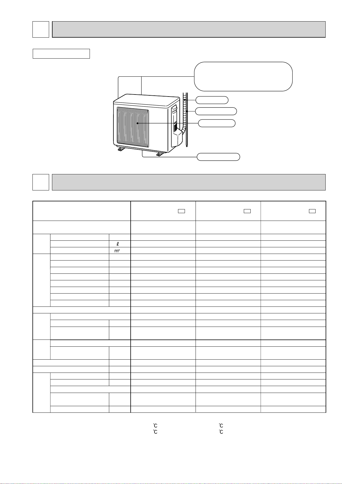
PART NAMES AND FUNCTIONS
OUTDOOR UNIT
MU-GA20VB
MU-GA25VB
MU-GA35VB
3
Capacity
Electrical
Coefficient of performance (C.O.P)
Compressor
Fan
Special
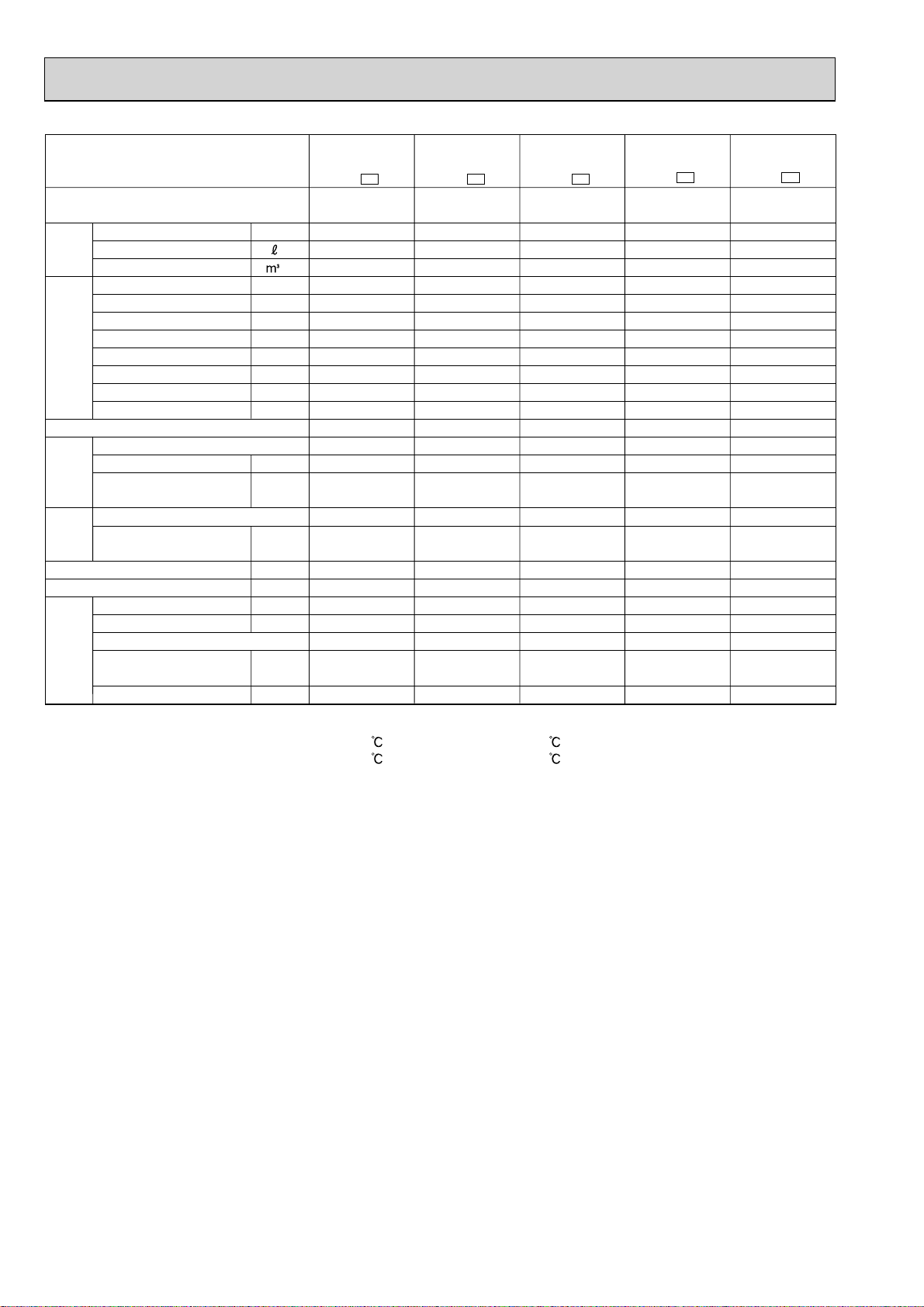
SPECIFICATION
Outdoor model
Outdoor unit power supply
Capacity
Dehumidification
Outdoor air flow
Breaker capacity
Running current
Power input
Auxiliary heater
Power factor
data
Starting current
Compressor motor current
Fan motor current
Model
Output
Winding
resistance (at 20 ºC)
Model
Winding
motor
resistance (at 20 ºC)
Dimensions W x H x D
Weight
Sound level
Fan speed
Fan speed regulator
Refrigerant filling
remarks
capacity (R410A)
Refrigeration oil (Model)
kW
/h
/h
A
A
W
A(kW)
%
A
A
A
W
Ω
Ω
mm
kg
dB
rpm
kg
cc
MU-GA20VB -
Single phase
230 V,50 Hz
2.3
0.9
1,800
10
3.17
715
–
98
21.0
2.76
0.245
3.22
RN092VHSHT
600
C-R 3.87
C-S 6.14
RA6V21-AC
WHT-BLK 366
BLK-RED 274
800 x 550 x 285
31
45
745
1
0.60
350 (NEO22)
Air inlet
back : MU-GA20VB
( )
MU-GA25VB
back and side : MU-GA35VB
Piping
Drain hose
Air outlet
Drain outlet
E1
MU-GA20VB -
Single phase
230 V,50 Hz
2.3
0.9
1,800
10
3.17
715
–
98
15.5
2.76
0.245
3.22
KN092VDMHC
650
C-R 3.62
C-S 5.40
RA6V21-AC
WHT-BLK 366
BLK-RED 274
800 x 550 x 285
27
45
745
1
0.60
350 (NEO22)
E2
MU-GA20VB -
Single phase
230 V,50 Hz
2.3
0.9
1,800
10
3.17
715
–
98
21.0
2.76
0.25
3.22
KN083VDMHC
500
C-R 4.52
C-S 7.07
RA6V21-AC
WHT-BLK 366
BLK-RED 274
800 x 550 x 285
27
45
745
1
0.65
350 (NEO22)
E3
NOTE : Test conditions are based on ISO 5151.
Cooling : Indoor Dry-bulb temperature 27 Wet-bulb temperature 19
Outdoor Dry-bulb temperature 35 Wet-bulb temperature 24
Indoor outdoor piping length : 5 m
3
Page 4
Outdoor model
Outdoor unit power supply
Capacity
Dehumidification
Outdoor air flow
Capacity
Breaker capacity
Running current
Power input
Auxiliary heater
Power factor
Electrical
data
Starting current
A(kW)
Compressor motor current
Fan motor current
Coefficient of performance (C.O.P)
Model
Output
Winding
resistance (at 20 ºC)
Compressor
Model
Winding
Fan
motor
resistance (at 20 ºC)
Dimensions W x H x D
Weight
Sound level
Fan speed
Fan speed regulator
Refrigerant filling
Special
remarks
capacity (R410A)
Refrigeration oil (Model)
kW
/h
/h
A
A
W
%
A
A
A
W
Ω
Ω
mm
kg
dB
rpm
kg
cc
MU-GA25VB
E1
-
Single phase
230 V, 50 Hz
2.5
1.1
1,800
10
3.40
775
–
99
21
2.99
0.245
3.23
RN092VHSHT
600
C-R 3.87
C-S 6.14
RA6V21-AC
WHT-BLK 366
BLK-RED 274
800 x 550 x 285
31
45
745
1
0.60
350 (NEO22)
MU-GA25VB
E2
-
Single phase
230 V,50 Hz
2.5
1.1
1,800
10
3.40
775
–
99
15.5
2.99
0.245
3.23
KN092VDMHC
650
C-R 3.62
C-S 5.40
RA6V21-AC
WHT-BLK 366
BLK-RED 274
800 x 550 x 285
27
45
745
1
0.60
350 (NEO22)
MU-GA35VB
E1
-
Single phase
230 V, 50 Hz
3.45
1.7
1,902
10
5.02
1,120
–
97
21
4.50
0.33
3.08
5PS132DAH01
900
C-R 2.80
C-S 5.43
RA6V33-KA
WHT-BLK 215
BLK-RED 307
800 x 550 x 285
30
49
855
1
0.70
350 (RB68A)
MU-GA35VB
E2
-
Single phase
230 V, 50 Hz
3.45
1.7
1,902
10
5.02
1,120
–
97
21
4.50
0.33
3.08
5PS132DAH01
900
C-R 2.80
C-S 5.43
RA6V33-KA
WHT-BLK 215
BLK-RED 307
800 x 550 x 285
34
49
855
1
0.90
350 (RB68A)
MU-GA35VB
E3
-
Single phase
230 V, 50 Hz
3.45
1.7
1,902
10
5.02
1,120
–
97
26
4.50
0.33
3.08
5PS132DAH01
900
C-R 2.80
C-S 5.43
RA6V33-KA
WHT-BLK 215
BLK-RED 307
800 x 550 x 285
34
49
855
1
1.05
350 (RB68A)
NOTE : Test conditions are based on ISO 5151.
Cooling : Indoor Dry-bulb temperature 27 Wet-bulb temperature 19
Outdoor Dry-bulb temperature 35 Wet-bulb temperature 24
Indoor outdoor piping length : 5 m
4
Page 5
4
NOISE CRITERIA CURVES
MU-GA20VB
MU-GA25VB
FUNCTION
COOL
SPL(dB
45
(A)
)LINE
MU-GA35VB
FUNCTION
COOL
SPL(dB
49
(A)
)LINE
Test conditions,
Cooling :Dry-bulb temperature 27 ºC Wet-bulb temperature 19 ºC
90
80
70
60
50
40
30
OCTAVE BAND SOUND PRESSURE LEVEL, dB re 0.0002 MICRO BAR
20
10
63 125 250 500 1000 2000 4000 8000
BAND CENTER FREQUENCIES, Hz
NC-10
NC-70
NC-60
NC-50
NC-40
NC-30
NC-20
Test conditions,
Cooling :Dry-bulb temperature 35 ºC Wet-bulb temperature 24 ºC
90
80
70
60
50
40
30
OCTAVE BAND SOUND PRESSURE LEVEL, dB re 0.0002 MICRO BAR
20
10
63 125 250 500 1000 2000 4000 8000
BAND CENTER FREQUENCIES, Hz
NC-10
NC-70
NC-60
NC-50
NC-40
NC-30
NC-20
OUTDOOR UNIT
1m
MICROPHONE
5
Page 6

5
OUTLINES AND DIMENSIONS
MU-GA20VB MU-GA25VB MU-GA35VB
OUTDOOR UNIT
344.5
285
550
44
Air in
(MU-GA35VB)
2 holes 10 x 21
22.3
Handle
280
10
400
Air in
Air out
150
302.5
500 Bolt pitch for installation
Drain hole 42
40
17.5
164.5
69
800
installation
Bolt pitch for
23
99.5
Service port
REQUIRED SPACE
100mm or more
304~325
Service panel
Liquid refrigerant pipe joint
Refrigerant pipe (flared) 6.35
35°
Gas refrigerant pipe joint
Refrigerant pipe (flared) 9.52
170.5
Unit: mm
Basically open 100mm or more
without any obstruction in front
and on both sides of the unit.
100mm or more
350mm or more
200mm or more
Open two sides of left,
right, or rear side.
43°
6
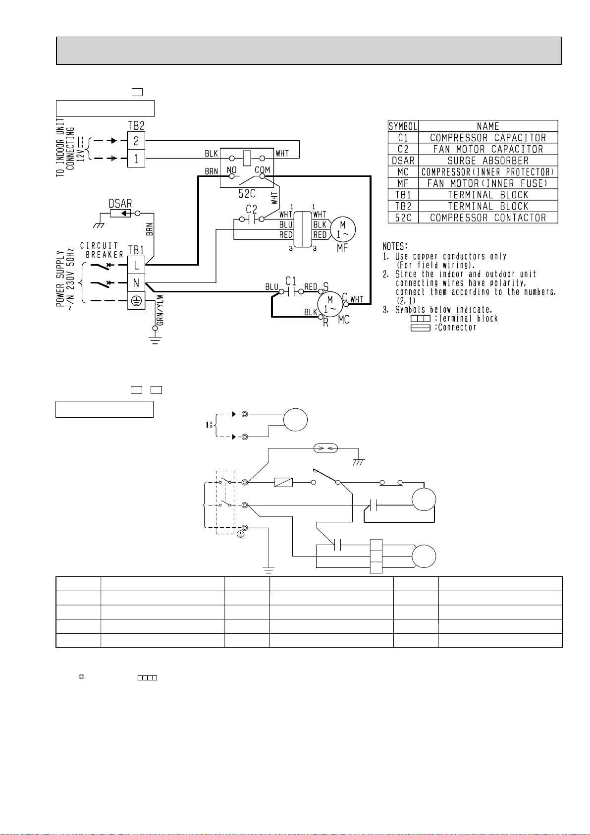
MU-GA20VB-
OUTDOOR UNIT
WIRING DIAGRAM
E1, E2
MU-GA25VB
TB2
12V
TO INDOOR
UNIT
CONNECTING
CIRCUIT
BREAKER
TB1
WHT
2
BLK
1
52C
BRN
DSAR
52C
BRN
COM
L
NO
BLU
N
POWER SUPPLY
~/N 230V 50Hz
PE
BLU
GRN/YLW
SYMBOL
C1
C2
DSAR
NOTE:1. About the indoor side electric wiring refer to the indoor unit electric wiring diagram for servicing.
2. Use copper conductors only. (For field wiring)
3. Symbols below indicate.
: Terminal block, : Connector
COMPRESSOR CAPACITOR
OUTDOOR FAN CAPACITOR
SURGE ABSORBER
NAME
SYMBOL
MC
MF
TB1
COMPRESSOR(INNER PROTECTOR)
OUTDOOR FAN MOTOR(INNER FUSE)
TERMINAL BLOCK
WHT
C2
RED
WHT
NAME NAME
6
WHT
C1
RED
BLK
3
2
1
SYMBOL
RED
BLK
WHT
TB2
52C
C
S
MC
R
MF
TERMINAL BLOCK
COMPRESSOR CONTACTOR
Page 7
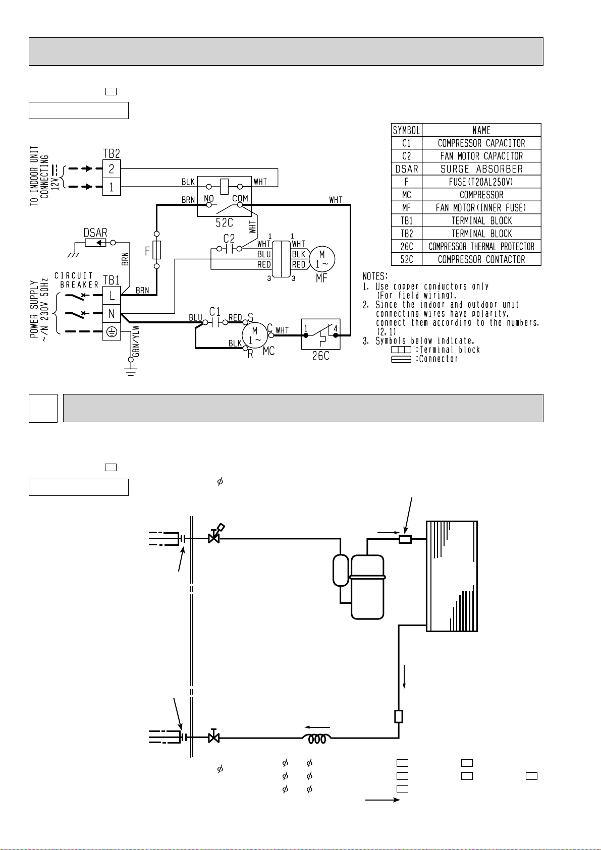
MU-GA20VB-
E3
OUTDOOR UNIT
MU-GA35VB-
OUTDOOR UNIT
SYMBOL
C1
C2
DSAR
NOTE:1. About the indoor side electric wiring refer to the indoor unit electric wiring diagram for servicing.
2. Use copper conductors only. (For field wiring)
3. Symbols below indicate.
: Terminal block, : Connector
COMPRESSOR CAPACITOR
OUTDOOR FAN CAPACITOR
SURGE ABSORBER
FUSE (T20AL250V)
F
E1, E2
NAME
12V
TO INDOOR
UNIT
CONNECTING
CIRCUIT
BREAKER
POWER SUPPLY
~/N 230V 50Hz
TB2
WHT
2
BLK
1
TB1
L
N
PE
SYMBOL
MC
MF
TB1
TB2
52C
DSAR
BRN
F
BRN
BLU
BLU
GRN/YLW
COMPRESSOR
OUTDOOR FAN MOTOR (INNER FUSE)
TERMINAL BLOCK
TERMINAL BLOCK
52C
WHT
C2
WHT
C1
RED
WHT
BRN
COM
NO
NAME NAME
51C
RED
WHT
S
C
MC
41
BLK
RED
3
BLK
2
1
WHT
SYMBOL
51C
52C
MF
R
OVERLOAD RELAY
COMPRESSOR CONTACTOR
7
Page 8
MU-GA35VB-
E3
OUTDOOR UNIT
7
REFRIGERANT SYSTEM DIAGRAM
MU-GA20VB
MU-GA25VB
MU-GA35VB-
E1
OUTDOOR UNIT
Flared connection
Flared connection
Refrigerant pipe 9.52
(with heat insulator)
Stop valve
(with service port)
Unit: mm
Muffler
(MU-GA20VB, MU-GA25VB)
Outdoor
heat
exchanger
Compressor
Stop valve
Refrigerant pipe 6.35
(with heat insulator)
Strainer
#100
Capillary tube
3.0 x 1.4 x 700 (MU-GA20VB-E1, MU-GA25VB-E1)
3.0 x 1.4 x 900 (MU-GA20VB-E2, MU-GA20VB-E3, MU-GA25VB-E2)
3.0 x 1.4 x 450 (MU-GA35VB
8
E1
-
)
Refrigerant flow in cooling
Page 9
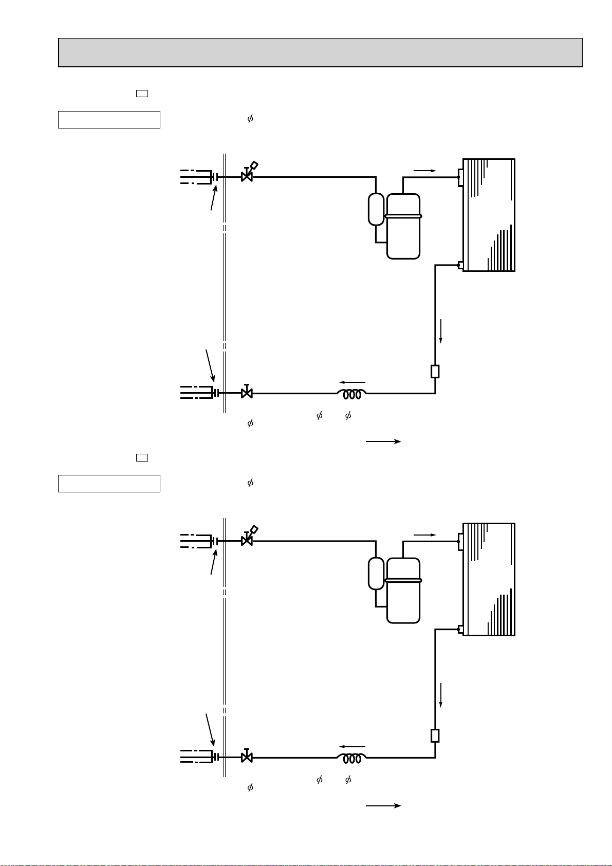
MU-GA35VB-
E2
OUTDOOR UNIT
Refrigerant pipe 9.52
(with heat insulator)
Flared connection
Flared connection
Unit: mm
Stop valve
(with service port)
Outdoor
heat
exchanger
Compressor
MU-GA35VB-
E3
OUTDOOR UNIT
Refrigerant pipe 6.35
(with heat insulator)
Refrigerant pipe 9.52
(with heat insulator)
Flared connection
Stop valve
Stop valve
(with service port)
Strainer
#100
Capillary tube
3.0 x 1.4 x 350
Refrigerant flow in cooling
Outdoor
heat
exchanger
Compressor
Flared connection
Refrigerant pipe 6.35
(with heat insulator)
Stop valve
Strainer
#100
Capillary tube
3.0 x 1.4 x 400
Refrigerant flow in cooling
9
Page 10

MAX. REFRIGERANT PIPING LENGTH
Model
MU-GA20VB
MU-GA25VB
MU-GA35VB
Refrigerant piping : m
Max. length
A
20
25
Max. height
B
10
Piping size O.D : mm Length of connecting pipe : m
Gas
9.52
MAX. HEIGHT DIFFERENCE
Indoor
unit
Refrigerant Piping
Max. Height
Max. length
B
ADDITIONAL REFRIGERANT CHARGE (R410A : g)
Model
MU-GA20VB -
MU-GA25VB
MU-GA20VB -
E1, E2
E3
Outdoor unit precharged
600
650
7m
Liquid
6.35
A
Refrigerant piping length (one way)
10m
15m
Indoor unit
Gas 0.43
Liquid 0.5
Outdoor unit
20m
Outdoor unit
Gas 0
Liquid 0
25m
MU-GA35VB -
MU-GA35VB -
MU-GA35VB -
E1
E2
E3
700
900
1,050
0
60
160
Calculation : Xg = 20g/m x (A-7) m
260
360
10
Page 11

8
PERFORMANCE CURVES
MU-GA20VB MU-GA25VB MU-A35VB
The standard specifications apply only to the operation of the air conditioner under normal conditions, since operating conditions vary according to the areas where these units are installed. The following information has been provided to clarify the
operating characteristics of the air conditioner under the conditions indicated by the performance curve.
(1) GUARANTEED VOLTAGE
198~264 V
(2) AIR FLOW
Air flow should be set at MAX.
(3) MAIN READINGS
(1) Indoor intake air wet-bulb temperature : °CWB
(2) Indoor outlet air wet-bulb temperature : °CWB
(3) Outdoor intake air dry-bulb temperature : °CDB
(4) Total input: W
Indoor air wet/dry-bulb temperature difference on the left side of the chart on next page shows the difference between the
indoor intake air wet/dry-bulb temperature and the indoor outlet air wet/dry-bulb temperature for your reference at service.
How to measure the indoor air wet-bulb/dry-bulb temperature difference
1. Attach at least 2 sets of wet-and dry-bulb thermometers to the indoor air intake as shown in the figure, and at least 2 sets
of wet-and dry-bulb thermometers to the indoor air outlet. The thermometers must be attached to the position where air
speed is high.
2. Attach at least 2 sets of wet-and dry-bulb thermometers to the outdoor air intake.
Cover the thermometers to prevent direct rays of the sun.
3. Check that the air filter is cleaned.
4. Open windows and doors of room.
5. Press the EMERGENCY OPERATION switch once to start the EMERGENCY COOL MODE.
6. When system stabilizes after more than 15 minutes, measure temperature and take an average temperature.
7. 10 minutes later, measure temperature again and check that the temperature does not change.
}
Cooling
INDOOR UNIT
Wet-and dry-bulb
thermometers
8-1. CAPACITY AND THE INPUT CURVES
9.6
8.8
8.0
7.2
6.5
5.7
11. 0
10.0
9.1
8.2
7.4
6.5
8.5
7.8
7.1
6.4
5.8
5.1
OUTDOOR UNIT
Wet-and dry-bulb
thermometers
MSC-GA25VB
MSC-GE25VB
MSC-GA20VB
MSC-GE20VB
MU-GA20VB
MSC-GA35VB
MSC-GE35VB
MU-GA35VB
MU-GA25VB
11
Page 12

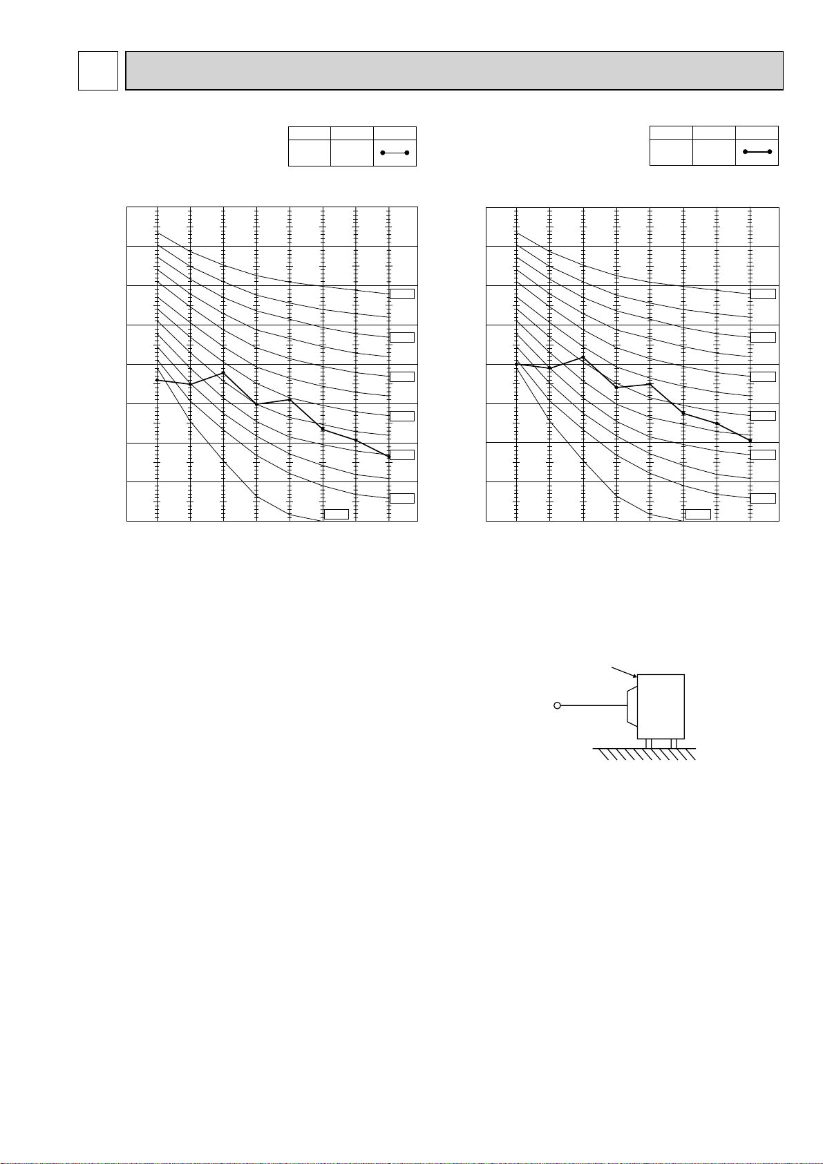
8-2. OUTDOOR LOW PRESSURE AND OUTDOOR UNIT CURRENT
COOL operation
Both indoor and outdoor unit are under the same temperature/humidity condition.
Dry-bulb temperature
20
25
30
Relative humidity(%)
50
60
70
Air flow should be set at MAX.
The unit of pressure has been changed to MPa on the international system of units (SI unit system).
The conversion factor is : 1 (MPa[Gauge]) = 10.2 (kgf/cm
(kgf/ [Gauge])(MPa[Gauge])
1.3
13
1.2
12
1.1
11
1.0
10
0.9
9
Outdoor low pressure
8
7
0.8
0.7
15 20
MU-GA20VB MU-GA20VB
230 V
18 32
50
25
6030 70
35
(%)
(°C)
Ambient temperature (˚C) Ambient humidity (%)
2
[Gauge] )
4
230 V
3
2
Outdoor unit current (A)
1
15 20
18 32
50
25
60
30
70 (%)
Ambient temperature (˚C) Ambient humidity (%)
35 (°C)
(kgf/ [Gauge])(MPa[Gauge])
1.2
12
1.1
11
1.0
10
0.9
9
0.8
8
Outdoor low pressure
7
6
0.7
0.6
15 20
Ambient temperature (˚C) Ambient humidity (%) Ambient temperature (˚C) Ambient humidity (%)
(kgf/ [Gauge])(MPa[Gauge])
Outdoor low pressure
13
12
10
1.3
1.2
1.1
11
1.0
0.9
9
0.8
8
0.7
7
15 20
Ambient temperature (˚C) Ambient humidity (%)
MU-GA25VB
230 V
18
50
25
6030 70
32
(%)
MU-GA35VB
18 32
50
25
6030 70
(%)
35 (°C)
230 V
35 (°C)
4
3
2
Outdoor unit current (A)
1
15 20
6
5
4
Outdoor unit current (A)
3
15 20
Ambient temperature (˚C) Ambient humidity (%)
12
MU-GA25VB
230 V
18 32
50
25
60
30
70 (%)
MU-GA35VB
230 V
18 32
50
25
60
30
70 (%)
35 (°C)
35 (°C)
Page 13

PERFORMANCE DATA
COOL operation (230V)
MSC-GA20VB, MSC-GE20VB: MU-GA20VB
CAPACITY : 2.3(kW) SHF : 0.74 INPUT : 715(W)
OUTDOOR DB(°C)
INDOOR
DB(
INDOOR
°C
)
WB(°C)
21 18 2.70 1.51 0.56 572 2.59 1.45 0.56 601 2.48 1.39 0.56 629 2.39 1.34 0.56 658
21 20 2.82 1.24 0.44 601 2.70 1.19 0.44 636 2.62 1.15 0.44 651 2.53 1.11 0.44 679
22 18 2.70 1.62 0.60 572 2.59 1.55 0.60 601 2.48 1.49 0.60 629 2.39 1.44 0.60 658
22 20 2.82 1.35 0.48 601 2.70 1.30 0.48 636 2.62 1.26 0.48 651 2.53 1.21 0.48 679
22 22 2.93 1.06 0.36 622 2.83 1.02 0.36 661 2.76 0.99 0.36 679 2.65 0.95 0.36 708
23 18 2.70 1.73 0.64 572 2.59 1.66 0.64 601 2.48 1.59 0.64 629 2.39 1.53 0.64 658
23 20 2.82 1.47 0.52 601 2.70 1.41 0.52 636 2.62 1.36 0.52 651 2.53 1.32 0.52 679
23 22 2.93 1.17 0.40 622 2.83 1.13 0.40 661 2.76 1.10 0.40 679 2.65 1.06 0.40 708
24 18 2.70 1.84 0.68 572 2.59 1.76 0.68 601 2.48 1.69 0.68 629 2.39 1.63 0.68 658
24 20 2.82 1.58 0.56 601 2.70 1.51 0.56 636 2.62 1.47 0.56 651 2.53 1.42 0.56 679
24 22 2.93 1.29 0.44 622 2.83 1.24 0.44 661 2.76 1.21 0.44 679 2.65 1.16 0.44 708
24 24 3.08 0.99 0.32 651 2.97 0.95 0.32 686 2.90 0.93 0.32 708 2.81 0.90 0.32 744
25 18 2.70 1.95 0.72 572 2.59 1.86 0.72 601 2.48 1.79 0.72 629 2.39 1.72 0.72 658
25 20 2.82 1.69 0.60 601 2.70 1.62 0.60 636 2.62 1.57 0.60 651 2.53 1.52 0.60 679
25 22 2.93 1.41 0.48 622 2.83 1.36 0.48 661 2.76 1.32 0.48 679 2.65 1.27 0.48 708
25 24 3.08 1.11 0.36 651 2.97 1.07 0.36 686 2.90 1.04 0.36 708 2.81 1.01 0.36 744
26 18 2.70 2.05 0.76 572 2.59 1.97 0.76 601 2.48 1.89 0.76 629 2.39 1.82 0.76 658
26 20 2.82 1.80 0.64 601 2.70 1.73 0.64 636 2.62 1.68 0.64 651 2.53 1.62 0.64 679
26 22 2.93 1.52 0.52 622 2.83 1.47 0.52 661 2.76 1.44 0.52 679 2.65 1.38 0.52 708
26 24 3.08 1.23 0.40 651 2.97 1.19 0.40 686 2.90 1.16 0.40 708 2.81 1.12 0.40 744
26 26 3.17 0.89 0.28 686 3.08 0.86 0.28 722 3.04 0.85 0.28 744 2.94 0.82 0.28 765
27 18 2.70 2.16 0.80 572 2.59 2.07 0.80 601 2.48 1.99 0.80 629 2.39 1.91 0.80 658
27 20 2.82 1.92 0.68 601 2.70 1.84 0.68 636 2.62 1.78 0.68 651 2.53 1.72 0.68 679
27 22 2.93 1.64 0.56 622 2.83 1.58 0.56 661 2.76 1.55 0.56 679 2.65 1.48 0.56 708
27 24 3.08 1.36 0.44 651 2.97 1.31 0.44 686 2.90 1.28 0.44 708 2.81 1.23 0.44 744
27 26 3.17 1.02 0.32 686 3.08 0.99 0.32 722 3.04 0.97 0.32 744 2.94 0.94 0.32 765
28 18 2.70 2.27 0.84 572 2.59 2.17 0.84 601 2.48 2.09 0.84 629 2.39 2.01 0.84 658
28 20 2.82 2.03 0.72 601 2.70 1.95 0.72 636 2.62 1.89 0.72 651 2.53 1.82 0.72 679
28 22 2.93 1.76 0.60 622 2.83 1.70 0.60 661 2.76 1.66 0.60 679 2.65 1.59 0.60 708
28 24 3.08 1.48 0.48 651 2.97 1.42 0.48 686 2.90 1.39 0.48 708 2.81 1.35 0.48 744
28 26 3.17 1.14 0.36 686 3.08 1.11 0.36 722 3.04 1.09 0.36 744 2.94 1.06 0.36 765
29 18 2.70 2.38 0.88 572 2.59 2.28 0.88 601 2.48 2.19 0.88 629 2.39 2.10 0.88 658
29 20 2.82 2.14 0.76 601 2.70 2.05 0.76 636 2.62 1.99 0.76 651 2.53 1.92 0.76 679
29 22 2.93 1.88 0.64 622 2.83 1.81 0.64 661 2.76 1.77 0.64 679 2.65 1.69 0.64 708
29 24 3.08 1.60 0.52 651 2.97 1.54 0.52 686 2.90 1.51 0.52 708 2.81 1.46 0.52 744
29 26 3.17 1.27 0.40 686 3.08 1.23 0.40 722 3.04 1.21 0.40 744 2.94 1.18 0.40 765
30 18 2.70 2.49 0.92 572 2.59 2.38 0.92 601 2.48 2.29 0.92 629 2.39 2.20 0.92 658
30 20 2.82 2.25 0.80 601 2.70 2.16 0.80 636 2.62 2.10 0.80 651 2.53 2.02 0.80 679
30 22 2.93 1.99 0.68 622 2.83 1.92 0.68 661 2.76 1.88 0.68 679 2.65 1.80 0.68 708
30 24 3.08 1.73 0.56 651 2.97 1.66 0.56 686 2.90 1.62 0.56 708 2.81 1.57 0.56 744
30 26 3.17 1.40 0.44 686 3.08 1.36 0.44 722 3.04 1.34 0.44 744 2.94 1.30 0.44 765
31 18 2.70 2.59 0.96 572 2.59 2.48 0.96 601 2.48 2.38 0.96 629 2.39 2.30 0.96 658
31 20 2.82 2.37 0.84 601 2.70 2.27 0.84 636 2.62 2.20 0.84 651 2.53 2.13 0.84 679
31 22 2.93 2.11 0.72 622 2.83 2.04 0.72 661 2.76 1.99 0.72 679 2.65 1.90 0.72 708
31 24 3.08 1.85 0.60 651 2.97 1.78 0.60 686 2.90 1.74 0.60 708 2.81 1.68 0.60 744
31 26 3.17 1.52 0.48 686 3.08 1.48 0.48 722 3.04 1.46 0.48 744 2.94 1.41 0.48 765
32 18 2.70 2.70 1.00 572 2.59 2.59 1.00 601 2.48 2.48 1.00 629 2.39 2.39 1.00 658
32 20 2.82 2.48 0.88 601 2.70 2.38 0.88 636 2.62 2.31 0.88 651 2.53 2.23 0.88 679
32 22 2.93 2.23 0.76 622 2.83 2.15 0.76 661 2.76 2.10 0.76 679 2.65 2.01 0.76 708
32 24 3.08 1.97 0.64 651 2.97 1.90 0.64 686 2.90 1.85 0.64 708 2.81 1.80 0.64 744
32 26 3.17 1.65 0.52 686 3.08 1.60 0.52 722 3.04 1.58 0.52 744 2.94 1.53 0.52 765
Q SHC SHF INPUT Q SHC SHF INPUT Q SHC SHF INPUT30Q SHC SHF INPUT
NOTE Q :Total capacity (kW) SHF :Sensible heat factor DB :Dry-bulb temperature
SHC :Sensible heat capacity (kW) INPUT :Total power input (W) WB :Wet-bulb temperature
21 2725
13
Page 14

PERFORMANCE DATA
COOL operation (230V)
MSC-GA20VB, MSC-GE20VB: MU-GA20VB
CAPACITY : 2.3(kW) SHF : 0.74 INPUT : 715(W)
OUTDOOR DB(°C)
INDOOR
DB(
INDOOR
°C
)
WB(°C)
21 18 2.25 1.26 0.56 701 2.07 1.16 0.56 744 1.99 1.11 0.56 758
21 20 2.37 1.04 0.44 729 2.21 0.97 0.44 765 2.13 0.94 0.44 787
22 18 2.25 1.35 0.60 701 2.07 1.24 0.60 744 1.99 1.19 0.60 758
22 20 2.37 1.14 0.48 729 2.21 1.06 0.48 765 2.13 1.02 0.48 787
22 22 2.51 0.90 0.36 758 2.35 0.84 0.36 801 2.27 0.82 0.36 815
23 18 2.25 1.44 0.64 701 2.07 1.32 0.64 744 1.99 1.27 0.64 758
23 20 2.37 1.23 0.52 729 2.21 1.15 0.52 765 2.13 1.11 0.52 787
23 22 2.51 1.00 0.40 758 2.35 0.94 0.40 801 2.27 0.91 0.40 815
24 18 2.25 1.53 0.68 701 2.07 1.41 0.68 744 1.99 1.35 0.68 758
24 20 2.37 1.33 0.56 729 2.21 1.24 0.56 765 2.13 1.19 0.56 787
24 22 2.51 1.10 0.44 758 2.35 1.03 0.44 801 2.27 1.00 0.44 815
24 24 2.65 0.85 0.32 787 2.48 0.79 0.32 822 2.42 0.77 0.32 840
25 18 2.25 1.62 0.72 701 2.07 1.49 0.72 744 1.99 1.43 0.72 758
25 20 2.37 1.42 0.60 729 2.21 1.32 0.60 765 2.13 1.28 0.60 787
25 22 2.51 1.20 0.48 758 2.35 1.13 0.48 801 2.27 1.09 0.48 815
25 24 2.65 0.95 0.36 787 2.48 0.89 0.36 822 2.42 0.87 0.36 840
26 18 2.25 1.71 0.76 701 2.07 1.57 0.76 744 1.99 1.51 0.76 758
26 20 2.37 1.52 0.64 729 2.21 1.41 0.64 765 2.13 1.36 0.64 787
26 22 2.51 1.30 0.52 758 2.35 1.22 0.52 801 2.27 1.18 0.52 815
26 24 2.65 1.06 0.40 787 2.48 0.99 0.40 822 2.42 0.97 0.40 840
26 26 2.78 0.78 0.28 815 2.62 0.73 0.28 851 2.54 0.71 0.28 869
27 18 2.25 1.80 0.80 701 2.07 1.66 0.80 744 1.99 1.59 0.80 758
27 20 2.37 1.61 0.68 729 2.21 1.50 0.68 765 2.13 1.45 0.68 787
27 22 2.51 1.40 0.56 758 2.35 1.31 0.56 801 2.27 1.27 0.56 815
27 24 2.65 1.16 0.44 787 2.48 1.09 0.44 822 2.42 1.06 0.44 840
27 26 2.78 0.89 0.32 815 2.62 0.84 0.32 851 2.54 0.81 0.32 869
28 18 2.25 1.89 0.84 701 2.07 1.74 0.84 744 1.99 1.67 0.84 758
28 20 2.37 1.71 0.72 729 2.21 1.59 0.72 765 2.13 1.53 0.72 787
28 22 2.51 1.50 0.60 758 2.35 1.41 0.60 801 2.27 1.36 0.60 815
28 24 2.65 1.27 0.48 787 2.48 1.19 0.48 822 2.42 1.16 0.48 840
28 26 2.78 1.00 0.36 815 2.62 0.94 0.36 851 2.54 0.91 0.36 869
29 18 2.25 1.98 0.88 701 2.07 1.82 0.88 744 1.99 1.75 0.88 758
29 20 2.37 1.80 0.76 729 2.21 1.68 0.76 765 2.13 1.62 0.76 787
29 22 2.51 1.60 0.64 758 2.35 1.50 0.64 801 2.27 1.45 0.64 815
29 24 2.65 1.38 0.52 787 2.48 1.29 0.52 822 2.42 1.26 0.52 840
29 26 2.78 1.11 0.40 815 2.62 1.05 0.40 851 2.54 1.02 0.40 869
30 18 2.25 2.07 0.92 701 2.07 1.90 0.92 744 1.99 1.83 0.92 758
30 20 2.37 1.90 0.80 729 2.21 1.77 0.80 765 2.13 1.70 0.80 787
30 22 2.51 1.70 0.68 758 2.35 1.60 0.68 801 2.27 1.54 0.68 815
30 24 2.65 1.48 0.56 787 2.48 1.39 0.56 822 2.42 1.35 0.56 840
30 26 2.78 1.22 0.44 815 2.62 1.15 0.44 851 2.54 1.12 0.44 869
31 18 2.25 2.16 0.96 701 2.07 1.99 0.96 744 1.99 1.91 0.96 758
31 20 2.37 1.99 0.84 729 2.21 1.85 0.84 765 2.13 1.79 0.84 787
31 22 2.51 1.81 0.72 758 2.35 1.69 0.72 801 2.27 1.63 0.72 815
31 24 2.65 1.59 0.60 787 2.48 1.49 0.60 822 2.42 1.45 0.60 840
31 26 2.78 1.34 0.48 815 2.62 1.26 0.48 851 2.54 1.22 0.48 869
32 18 2.25 2.25 1.00 701 2.07 2.07 1.00 744 1.99 1.99 1.00 758
32 20 2.37 2.08 0.88 729 2.21 1.94 0.88 765 2.13 1.87 0.88 787
32 22 2.51 1.91 0.76 758 2.35 1.78 0.76 801 2.27 1.72 0.76 815
32 24 2.65 1.69 0.64 787 2.48 1.59 0.64 822 2.42 1.55 0.64 840
32 26 2.78 1.45 0.52 815 2.62 1.36 0.52 851 2.54 1.32 0.52 869
Q SHC SHF INPUT Q SHC SHF INPUT Q SHC SHF INPUT
NOTE Q :Total capacity (kW) SHF :Sensible heat factor DB :Dry-bulb temperature
SHC :Sensible heat capacity (kW) INPUT :Total power input (W) WB :Wet-bulb temperature
35 4340
14
Page 15

PERFORMANCE DATA
COOL operation (230V)
MSC-GA25VB, MSC-GE25VB: MU-GA25VB
CAPACITY : 2.5(kW) SHF : 0.70 INPUT : 775(W)
OUTDOOR DB(°C)
INDOOR
DB(
INDOOR
°C
)
WB(°C)
21 18 2.94 1.53 0.52 620 2.81 1.46 0.52 651 2.70 1.40 0.52 682 2.60 1.35 0.52 713
21 20 3.06 1.23 0.40 651 2.94 1.18 0.40 690 2.85 1.14 0.40 705 2.75 1.10 0.40 736
22 18 2.94 1.65 0.56 620 2.81 1.58 0.56 651 2.70 1.51 0.56 682 2.60 1.46 0.56 713
22 20 3.06 1.35 0.44 651 2.94 1.29 0.44 690 2.85 1.25 0.44 705 2.75 1.21 0.44 736
22 22 3.19 1.02 0.32 674 3.08 0.98 0.32 717 3.00 0.96 0.32 736 2.88 0.92 0.32 767
23 18 2.94 1.76 0.60 620 2.81 1.69 0.60 651 2.70 1.62 0.60 682 2.60 1.56 0.60 713
23 20 3.06 1.47 0.48 651 2.94 1.41 0.48 690 2.85 1.37 0.48 705 2.75 1.32 0.48 736
23 22 3.19 1.15 0.36 674 3.08 1.11 0.36 717 3.00 1.08 0.36 736 2.88 1.04 0.36 767
24 18 2.94 1.88 0.64 620 2.81 1.80 0.64 651 2.70 1.73 0.64 682 2.60 1.66 0.64 713
24 20 3.06 1.59 0.52 651 2.94 1.53 0.52 690 2.85 1.48 0.52 705 2.75 1.43 0.52 736
24 22 3.19 1.28 0.40 674 3.08 1.23 0.40 717 3.00 1.20 0.40 736 2.88 1.15 0.40 767
24 24 3.35 0.94 0.28 705 3.23 0.90 0.28 744 3.15 0.88 0.28 767 3.05 0.85 0.28 806
25 18 2.94 2.00 0.68 620 2.81 1.91 0.68 651 2.70 1.84 0.68 682 2.60 1.77 0.68 713
25 20 3.06 1.72 0.56 651 2.94 1.65 0.56 690 2.85 1.60 0.56 705 2.75 1.54 0.56 736
25 22 3.19 1.40 0.44 674 3.08 1.35 0.44 717 3.00 1.32 0.44 736 2.88 1.27 0.44 767
25 24 3.35 1.07 0.32 705 3.23 1.03 0.32 744 3.15 1.01 0.32 767 3.05 0.98 0.32 806
26 18 2.94 2.12 0.72 620 2.81 2.03 0.72 651 2.70 1.94 0.72 682 2.60 1.87 0.72 713
26 20 3.06 1.84 0.60 651 2.94 1.76 0.60 690 2.85 1.71 0.60 705 2.75 1.65 0.60 736
26 22 3.19 1.53 0.48 674 3.08 1.48 0.48 717 3.00 1.44 0.48 736 2.88 1.38 0.48 767
26 24 3.35 1.21 0.36 705 3.23 1.16 0.36 744 3.15 1.13 0.36 767 3.05 1.10 0.36 806
26 26 3.45 0.83 0.24 744 3.35 0.80 0.24 783 3.30 0.79 0.24 806 3.20 0.77 0.24 829
27 18 2.94 2.23 0.76 620 2.81 2.14 0.76 651 2.70 2.05 0.76 682 2.60 1.98 0.76 713
27 20 3.06 1.96 0.64 651 2.94 1.88 0.64 690 2.85 1.82 0.64 705 2.75 1.76 0.64 736
27 22 3.19 1.66 0.52 674 3.08 1.60 0.52 717 3.00 1.56 0.52 736 2.88 1.50 0.52 767
27 24 3.35 1.34 0.40 705 3.23 1.29 0.40 744 3.15 1.26 0.40 767 3.05 1.22 0.40 806
27 26 3.45 0.97 0.28 744 3.35 0.94 0.28 783 3.30 0.92 0.28 806 3.20 0.90 0.28 829
28 18 2.94 2.35 0.80 620 2.81 2.25 0.80 651 2.70 2.16 0.80 682 2.60 2.08 0.80 713
28 20 3.06 2.08 0.68 651 2.94 2.00 0.68 690 2.85 1.94 0.68 705 2.75 1.87 0.68 736
28 22 3.19 1.79 0.56 674 3.08 1.72 0.56 717 3.00 1.68 0.56 736 2.88 1.61 0.56 767
28 24 3.35 1.47 0.44 705 3.23 1.42 0.44 744 3.15 1.39 0.44 767 3.05 1.34 0.44 806
28 26 3.45 1.10 0.32 744 3.35 1.07 0.32 783 3.30 1.06 0.32 806 3.20 1.02 0.32 829
29 18 2.94 2.47 0.84 620 2.81 2.36 0.84 651 2.70 2.27 0.84 682 2.60 2.18 0.84 713
29 20 3.06 2.21 0.72 651 2.94 2.12 0.72 690 2.85 2.05 0.72 705 2.75 1.98 0.72 736
29 22 3.19 1.91 0.60 674 3.08 1.85 0.60 717 3.00 1.80 0.60 736 2.88 1.73 0.60 767
29 24 3.35 1.61 0.48 705 3.23 1.55 0.48 744 3.15 1.51 0.48 767 3.05 1.46 0.48 806
29 26 3.45 1.24 0.36 744 3.35 1.21 0.36 783 3.30 1.19 0.36 806 3.20 1.15 0.36 829
30 18 2.94 2.59 0.88 620 2.81 2.48 0.88 651 2.70 2.38 0.88 682 2.60 2.29 0.88 713
30 20 3.06 2.33 0.76 651 2.94 2.23 0.76 690 2.85 2.17 0.76 705 2.75 2.09 0.76 736
30 22 3.19 2.04 0.64 674 3.08 1.97 0.64 717 3.00 1.92 0.64 736 2.88 1.84 0.64 767
30 24 3.35 1.74 0.52 705 3.23 1.68 0.52 744 3.15 1.64 0.52 767 3.05 1.59 0.52 806
30 26 3.45 1.38 0.40 744 3.35 1.34 0.40 783 3.30 1.32 0.40 806 3.20 1.28 0.40 829
31 18 2.94 2.70 0.92 620 2.81 2.59 0.92 651 2.70 2.48 0.92 682 2.60 2.39 0.92 713
31 20 3.06 2.45 0.80 651 2.94 2.35 0.80 690 2.85 2.28 0.80 705 2.75 2.20 0.80 736
31 22 3.19 2.17 0.68 674 3.08 2.09 0.68 717 3.00 2.04 0.68 736 2.88 1.96 0.68 767
31 24 3.35 1.88 0.56 705 3.23 1.81 0.56 744 3.15 1.76 0.56 767 3.05 1.71 0.56 806
31 26 3.45 1.52 0.44 744 3.35 1.47 0.44 783 3.30 1.45 0.44 806 3.20 1.41 0.44 829
32 18 2.94 2.82 0.96 620 2.81 2.70 0.96 651 2.70 2.59 0.96 682 2.60 2.50 0.96 713
32 20 3.06 2.57 0.84 651 2.94 2.47 0.84 690 2.85 2.39 0.84 705 2.75 2.31 0.84 736
32 22 3.19 2.30 0.72 674 3.08 2.21 0.72 717 3.00 2.16 0.72 736 2.88 2.07 0.72 767
32 24 3.35 2.01 0.60 705 3.23 1.94 0.60 744 3.15 1.89 0.60 767 3.05 1.83 0.60 806
32 26 3.45 1.66 0.48 744 3.35 1.61 0.48 783 3.30 1.58 0.48 806 3.20 1.54 0.48 829
Q SHC SHF INPUT Q SHC SHF INPUT Q SHC SHF INPUT30Q SHC SHF INPUT
NOTE Q :Total capacity (kW) SHF :Sensible heat factor DB :Dry-bulb temperature
SHC :Sensible heat capacity (kW) INPUT :Total power input (W) WB :Wet-bulb temperature
21 2725
15
Page 16

PERFORMANCE DATA
COOL operation (230V)
MSC-GA25VB, MSC-GE25VB: MU-GA25VB
CAPACITY : 2.5(kW) SHF : 0.70 INPUT : 775(W)
OUTDOOR DB(°C)
INDOOR
DB(
INDOOR
°C
)
WB(°C)
21 18 2.45 1.27 0.52 760 2.25 1.17 0.52 806 2.16 1.12 0.52 822
21 20 2.58 1.03 0.40 791 2.40 0.96 0.40 829 2.31 0.93 0.40 853
22 18 2.45 1.37 0.56 760 2.25 1.26 0.56 806 2.16 1.21 0.56 822
22 20 2.58 1.13 0.44 791 2.40 1.06 0.44 829 2.31 1.02 0.44 853
22 22 2.73 0.87 0.32 822 2.55 0.82 0.32 868 2.46 0.79 0.32 884
23 18 2.45 1.47 0.60 760 2.25 1.35 0.60 806 2.16 1.30 0.60 822
23 20 2.58 1.24 0.48 791 2.40 1.15 0.48 829 2.31 1.11 0.48 853
23 22 2.73 0.98 0.36 822 2.55 0.92 0.36 868 2.46 0.89 0.36 884
24 18 2.45 1.57 0.64 760 2.25 1.44 0.64 806 2.16 1.38 0.64 822
24 20 2.58 1.34 0.52 791 2.40 1.25 0.52 829 2.31 1.20 0.52 853
24 22 2.73 1.09 0.40 822 2.55 1.02 0.40 868 2.46 0.99 0.40 884
24 24 2.88 0.81 0.28 853 2.70 0.76 0.28 891 2.63 0.74 0.28 911
25 18 2.45 1.67 0.68 760 2.25 1.53 0.68 806 2.16 1.47 0.68 822
25 20 2.58 1.44 0.56 791 2.40 1.34 0.56 829 2.31 1.30 0.56 853
25 22 2.73 1.20 0.44 822 2.55 1.12 0.44 868 2.46 1.08 0.44 884
25 24 2.88 0.92 0.32 853 2.70 0.86 0.32 891 2.63 0.84 0.32 911
26 18 2.45 1.76 0.72 760 2.25 1.62 0.72 806 2.16 1.56 0.72 822
26 20 2.58 1.55 0.60 791 2.40 1.44 0.60 829 2.31 1.39 0.60 853
26 22 2.73 1.31 0.48 822 2.55 1.22 0.48 868 2.46 1.18 0.48 884
26 24 2.88 1.04 0.36 853 2.70 0.97 0.36 891 2.63 0.95 0.36 911
26 26 3.03 0.73 0.24 884 2.85 0.68 0.24 922 2.76 0.66 0.24 942
27 18 2.45 1.86 0.76 760 2.25 1.71 0.76 806 2.16 1.64 0.76 822
27 20 2.58 1.65 0.64 791 2.40 1.54 0.64 829 2.31 1.48 0.64 853
27 22 2.73 1.42 0.52 822 2.55 1.33 0.52 868 2.46 1.28 0.52 884
27 24 2.88 1.15 0.40 853 2.70 1.08 0.40 891 2.63 1.05 0.40 911
27 26 3.03 0.85 0.28 884 2.85 0.80 0.28 922 2.76 0.77 0.28 942
28 18 2.45 1.96 0.80 760 2.25 1.80 0.80 806 2.16 1.73 0.80 822
28 20 2.58 1.75 0.68 791 2.40 1.63 0.68 829 2.31 1.57 0.68 853
28 22 2.73 1.53 0.56 822 2.55 1.43 0.56 868 2.46 1.38 0.56 884
28 24 2.88 1.27 0.44 853 2.70 1.19 0.44 891 2.63 1.16 0.44 911
28 26 3.03 0.97 0.32 884 2.85 0.91 0.32 922 2.76 0.88 0.32 942
29 18 2.45 2.06 0.84 760 2.25 1.89 0.84 806 2.16 1.82 0.84 822
29 20 2.58 1.85 0.72 791 2.40 1.73 0.72 829 2.31 1.67 0.72 853
29 22 2.73 1.64 0.60 822 2.55 1.53 0.60 868 2.46 1.48 0.60 884
29 24 2.88 1.38 0.48 853 2.70 1.30 0.48 891 2.63 1.26 0.48 911
29 26 3.03 1.09 0.36 884 2.85 1.03 0.36 922 2.76 0.99 0.36 942
30 18 2.45 2.16 0.88 760 2.25 1.98 0.88 806 2.16 1.90 0.88 822
30 20 2.58 1.96 0.76 791 2.40 1.82 0.76 829 2.31 1.76 0.76 853
30 22 2.73 1.74 0.64 822 2.55 1.63 0.64 868 2.46 1.58 0.64 884
30 24 2.88 1.50 0.52 853 2.70 1.40 0.52 891 2.63 1.37 0.52 911
30 26 3.03 1.21 0.40 884 2.85 1.14 0.40 922 2.76 1.11 0.40 942
31 18 2.45 2.25 0.92 760 2.25 2.07 0.92 806 2.16 1.99 0.92 822
31 20 2.58 2.06 0.80 791 2.40 1.92 0.80 829 2.31 1.85 0.80 853
31 22 2.73 1.85 0.68 822 2.55 1.73 0.68 868 2.46 1.67 0.68 884
31 24 2.88 1.61 0.56 853 2.70 1.51 0.56 891 2.63 1.47 0.56 911
31 26 3.03 1.33 0.44 884 2.85 1.25 0.44 922 2.76 1.22 0.44 942
32 18 2.45 2.35 0.96 760 2.25 2.16 0.96 806 2.16 2.08 0.96 822
32 20 2.58 2.16 0.84 791 2.40 2.02 0.84 829 2.31 1.94 0.84 853
32 22 2.73 1.96 0.72 822 2.55 1.84 0.72 868 2.46 1.77 0.72 884
32 24 2.88 1.73 0.60 853 2.70 1.62 0.60 891 2.63 1.58 0.60 911
32 26 3.03 1.45 0.48 884 2.85 1.37 0.48 922 2.76 1.33 0.48 942
Q SHC SHF INPUT Q SHC SHF INPUT Q SHC SHF INPUT
NOTE Q :Total capacity (kW) SHF :Sensible heat factor DB :Dry-bulb temperature
SHC :Sensible heat capacity (kW) INPUT :Total power input (W) WB :Wet-bulb temperature
35 4340
16
Page 17

PERFORMANCE DATA
COOL operation (230V)
MSC-GA35VB, MSC-GE35VB: MU-GA35VB
CAPACITY : 3.45(kW) SHF : 0.66 INPUT : 1120(W)
OUTDOOR DB(˚C)
INDOOR
DB(
INDOOR
˚C
)
WB(˚C)
21 18 4.05 1.95 0.48 896 3.88 1.86 0.48 941 3.73 1.79 0.48 986 3.59 1.72 0.48 1030
21 20 4.23 1.52 0.36 941 4.05 1.46 0.36 997 3.93 1.42 0.36 1019 3.80 1.37 0.36 1064
22 18 4.05 2.11 0.52 896 3.88 2.02 0.52 941 3.73 1.94 0.52 986 3.59 1.87 0.52 1030
22 20 4.23 1.69 0.40 941 4.05 1.62 0.40 997 3.93 1.57 0.40 1019 3.80 1.52 0.40 1064
22 22 4.40 1.23 0.28 974 4.24 1.19 0.28 1036 4.14 1.16 0.28 1064 3.97 1.11 0.28 1109
23 18 4.05 2.27 0.56 896 3.88 2.17 0.56 941 3.73 2.09 0.56 986 3.59 2.01 0.56 1030
23 20 4.23 1.86 0.44 941 4.05 1.78 0.44 997 3.93 1.73 0.44 1019 3.80 1.67 0.44 1064
23 22 4.40 1.41 0.32 974 4.24 1.36 0.32 1036 4.14 1.32 0.32 1064 3.97 1.27 0.32 1109
24 18 4.05 2.43 0.60 896 3.88 2.33 0.60 941 3.73 2.24 0.60 986 3.59 2.15 0.60 1030
24 20 4.23 2.03 0.48 941 4.05 1.95 0.48 997 3.93 1.89 0.48 1019 3.80 1.82 0.48 1064
24 22 4.40 1.58 0.36 974 4.24 1.53 0.36 1036 4.14 1.49 0.36 1064 3.97 1.43 0.36 1109
24 24 4.62 1.11 0.24 1019 4.45 1.07 0.24 1075 4.35 1.04 0.24 1109 4.21 1.01 0.24 1165
25 18 4.05 2.59 0.64 896 3.88 2.48 0.64 941 3.73 2.38 0.64 986 3.59 2.30 0.64 1030
25 20 4.23 2.20 0.52 941 4.05 2.11 0.52 997 3.93 2.05 0.52 1019 3.80 1.97 0.52 1064
25 22 4.40 1.76 0.40 974 4.24 1.70 0.40 1036 4.14 1.66 0.40 1064 3.97 1.59 0.40 1109
25 24 4.62 1.29 0.28 1019 4.45 1.25 0.28 1075 4.35 1.22 0.28 1109 4.21 1.18 0.28 1165
26 18 4.05 2.76 0.68 896 3.88 2.64 0.68 941 3.73 2.53 0.68 986 3.59 2.44 0.68 1030
26 20 4.23 2.37 0.56 941 4.05 2.27 0.56 997 3.93 2.20 0.56 1019 3.80 2.13 0.56 1064
26 22 4.40 1.94 0.44 974 4.24 1.87 0.44 1036 4.14 1.82 0.44 1064 3.97 1.75 0.44 1109
26 24 4.62 1.48 0.32 1019 4.45 1.42 0.32 1075 4.35 1.39 0.32 1109 4.21 1.35 0.32 1165
26 26 4.76 0.95 0.20 1075 4.62 0.92 0.20 1131 4.55 0.91 0.20 1165 4.42 0.88 0.20 1198
27 18 4.05 2.92 0.72 896 3.88 2.79 0.72 941 3.73 2.68 0.72 986 3.59 2.58 0.72 1030
27 20 4.23 2.54 0.60 941 4.05 2.43 0.60 997 3.93 2.36 0.60 1019 3.80 2.28 0.60 1064
27 22 4.40 2.11 0.48 974 4.24 2.04 0.48 1036 4.14 1.99 0.48 1064 3.97 1.90 0.48 1109
27 24 4.62 1.66 0.36 1019 4.45 1.60 0.36 1075 4.35 1.56 0.36 1109 4.21 1.52 0.36 1165
27 26 4.76 1.14 0.24 1075 4.62 1.11 0.24 1131 4.55 1.09 0.24 1165 4.42 1.06 0.24 1198
28 18 4.05 3.08 0.76 896 3.88 2.95 0.76 941 3.73 2.83 0.76 986 3.59 2.73 0.76 1030
28 20 4.23 2.70 0.64 941 4.05 2.59 0.64 997 3.93 2.52 0.64 1019 3.80 2.43 0.64 1064
28 22 4.40 2.29 0.52 974 4.24 2.21 0.52 1036 4.14 2.15 0.52 1064 3.97 2.06 0.52 1109
28 24 4.62 1.85 0.40 1019 4.45 1.78 0.40 1075 4.35 1.74 0.40 1109 4.21 1.68 0.40 1165
28 26 4.76 1.33 0.28 1075 4.62 1.29 0.28 1131 4.55 1.28 0.28 1165 4.42 1.24 0.28 1198
29 18 4.05 3.24 0.80 896 3.88 3.11 0.80 941 3.73 2.98 0.80 986 3.59 2.87 0.80 1030
29 20 4.23 2.87 0.68 941 4.05 2.76 0.68 997 3.93 2.67 0.68 1019 3.80 2.58 0.68 1064
29 22 4.40 2.46 0.56 974 4.24 2.38 0.56 1036 4.14 2.32 0.56 1064 3.97 2.22 0.56 1109
29 24 4.62 2.03 0.44 1019 4.45 1.96 0.44 1075 4.35 1.91 0.44 1109 4.21 1.85 0.44 1165
29 26 4.76 1.52 0.32 1075 4.62 1.48 0.32 1131 4.55 1.46 0.32 1165 4.42 1.41 0.32 1198
30 18 4.05 3.41 0.84 896 3.88 3.26 0.84 941 3.73 3.13 0.84 986 3.59 3.01 0.84 1030
30 20 4.23 3.04 0.72 941 4.05 2.92 0.72 997 3.93 2.83 0.72 1019 3.80 2.73 0.72 1064
30 22 4.40 2.64 0.60 974 4.24 2.55 0.60 1036 4.14 2.48 0.60 1064 3.97 2.38 0.60 1109
30 24 4.62 2.22 0.48 1019 4.45 2.14 0.48 1075 4.35 2.09 0.48 1109 4.21 2.02 0.48 1165
30 26 4.76 1.71 0.36 1075 4.62 1.66 0.36 1131 4.55 1.64 0.36 1165 4.42 1.59 0.36 1198
31 18 4.05 3.57 0.88 896 3.88 3.42 0.88 941 3.73 3.28 0.88 986 3.59 3.16 0.88 1030
31 20 4.23 3.21 0.76 941 4.05 3.08 0.76 997 3.93 2.99 0.76 1019 3.80 2.88 0.76 1064
31 22 4.40 2.82 0.64 974 4.24 2.72 0.64 1036 4.14 2.65 0.64 1064 3.97 2.54 0.64 1109
31 24 4.62 2.40 0.52 1019 4.45 2.31 0.52 1075 4.35 2.26 0.52 1109 4.21 2.19 0.52 1165
31 26 4.76 1.90 0.40 1075 4.62 1.85 0.40 1131 4.55 1.82 0.40 1165 4.42 1.77 0.40 1198
32 18 4.05 3.73 0.92 896 3.88 3.57 0.92 941 3.73 3.43 0.92 986 3.59 3.30 0.92 1030
32 20 4.23 3.38 0.80 941 4.05 3.24 0.80 997 3.93 3.15 0.80 1019 3.80 3.04 0.80 1064
32 22 4.40 2.99 0.68 974 4.24 2.89 0.68 1036 4.14 2.82 0.68 1064 3.97 2.70 0.68 1109
32 24 4.62 2.59 0.56 1019 4.45 2.49 0.56 1075 4.35 2.43 0.56 1109 4.21 2.36 0.56 1165
32 26 4.76 2.09 0.44 1075 4.62 2.03 0.44 1131 4.55 2.00 0.44 1165 4.42 1.94 0.44 1198
Q SHC SHF INPUT Q SHC SHF INPUT Q SHC SHF INPUT30Q SHC SHF INPUT
NOTE Q :Total capacity (kW) SHF :Sensible heat factor DB :Dry-bulb temperature
SHC :Sensible heat capacity (kW) INPUT :Total power input (W) WB :Wet-bulb temperature
21 2725
17
Page 18

PERFORMANCE DATA
COOL operation (230V)
MSC-GA35VB, MSC-GE35VB: MU-GA35VB
CAPACITY : 3.45(kW) SHF : 0.66 INPUT : 1120(W)
OUTDOOR DB(°C)
INDOOR
DB(
INDOOR
°C
)
WB(°C)
21 18 3.38 1.62 0.48 1098 3.11 1.49 0.48 1165 2.98 1.43 0.48 1187
21 20 3.55 1.28 0.36 1142 3.31 1.19 0.36 1198 3.19 1.15 0.36 1232
22 18 3.38 1.76 0.52 1098 3.11 1.61 0.52 1165 2.98 1.55 0.52 1187
22 20 3.55 1.42 0.40 1142 3.31 1.32 0.40 1198 3.19 1.28 0.40 1232
22 22 3.76 1.05 0.28 1187 3.52 0.99 0.28 1254 3.40 0.95 0.28 1277
23 18 3.38 1.89 0.56 1098 3.11 1.74 0.56 1165 2.98 1.67 0.56 1187
23 20 3.55 1.56 0.44 1142 3.31 1.46 0.44 1198 3.19 1.40 0.44 1232
23 22 3.76 1.20 0.32 1187 3.52 1.13 0.32 1254 3.40 1.09 0.32 1277
24 18 3.38 2.03 0.60 1098 3.11 1.86 0.60 1165 2.98 1.79 0.60 1187
24 20 3.55 1.71 0.48 1142 3.31 1.59 0.48 1198 3.19 1.53 0.48 1232
24 22 3.76 1.35 0.36 1187 3.52 1.27 0.36 1254 3.40 1.22 0.36 1277
24 24 3.97 0.95 0.24 1232 3.73 0.89 0.24 1288 3.62 0.87 0.24 1316
25 18 3.38 2.16 0.64 1098 3.11 1.99 0.64 1165 2.98 1.91 0.64 1187
25 20 3.55 1.85 0.52 1142 3.31 1.72 0.52 1198 3.19 1.66 0.52 1232
25 22 3.76 1.50 0.40 1187 3.52 1.41 0.40 1254 3.40 1.36 0.40 1277
25 24 3.97 1.11 0.28 1232 3.73 1.04 0.28 1288 3.62 1.01 0.28 1316
26 18 3.38 2.30 0.68 1098 3.11 2.11 0.68 1165 2.98 2.03 0.68 1187
26 20 3.55 1.99 0.56 1142 3.31 1.85 0.56 1198 3.19 1.79 0.56 1232
26 22 3.76 1.65 0.44 1187 3.52 1.55 0.44 1254 3.40 1.50 0.44 1277
26 24 3.97 1.27 0.32 1232 3.73 1.19 0.32 1288 3.62 1.16 0.32 1316
26 26 4.17 0.83 0.20 1277 3.93 0.79 0.20 1333 3.81 0.76 0.20 1361
27 18 3.38 2.43 0.72 1098 3.11 2.24 0.72 1165 2.98 2.15 0.72 1187
27 20 3.55 2.13 0.60 1142 3.31 1.99 0.60 1198 3.19 1.91 0.60 1232
27 22 3.76 1.81 0.48 1187 3.52 1.69 0.48 1254 3.40 1.63 0.48 1277
27 24 3.97 1.43 0.36 1232 3.73 1.34 0.36 1288 3.62 1.30 0.36 1316
27 26 4.17 1.00 0.24 1277 3.93 0.94 0.24 1333 3.81 0.91 0.24 1361
28 18 3.38 2.57 0.76 1098 3.11 2.36 0.76 1165 2.98 2.27 0.76 1187
28 20 3.55 2.27 0.64 1142 3.31 2.12 0.64 1198 3.19 2.04 0.64 1232
28 22 3.76 1.96 0.52 1187 3.52 1.83 0.52 1254 3.40 1.77 0.52 1277
28 24 3.97 1.59 0.40 1232 3.73 1.49 0.40 1288 3.62 1.45 0.40 1316
28 26 4.17 1.17 0.28 1277 3.93 1.10 0.28 1333 3.81 1.07 0.28 1361
29 18 3.38 2.70 0.80 1098 3.11 2.48 0.80 1165 2.98 2.39 0.80 1187
29 20 3.55 2.42 0.68 1142 3.31 2.25 0.68 1198 3.19 2.17 0.68 1232
29 22 3.76 2.11 0.56 1187 3.52 1.97 0.56 1254 3.40 1.90 0.56 1277
29 24 3.97 1.75 0.44 1232 3.73 1.64 0.44 1288 3.62 1.59 0.44 1316
29 26 4.17 1.34 0.32 1277 3.93 1.26 0.32 1333 3.81 1.22 0.32 1361
30 18 3.38 2.84 0.84 1098 3.11 2.61 0.84 1165 2.98 2.51 0.84 1187
30 20 3.55 2.56 0.72 1142 3.31 2.38 0.72 1198 3.19 2.30 0.72 1232
30 22 3.76 2.26 0.60 1187 3.52 2.11 0.60 1254 3.40 2.04 0.60 1277
30 24 3.97 1.90 0.48 1232 3.73 1.79 0.48 1288 3.62 1.74 0.48 1316
30 26 4.17 1.50 0.36 1277 3.93 1.42 0.36 1333 3.81 1.37 0.36 1361
31 18 3.38 2.98 0.88 1098 3.11 2.73 0.88 1165 2.98 2.63 0.88 1187
31 20 3.55 2.70 0.76 1142 3.31 2.52 0.76 1198 3.19 2.43 0.76 1232
31 22 3.76 2.41 0.64 1187 3.52 2.25 0.64 1254 3.40 2.17 0.64 1277
31 24 3.97 2.06 0.52 1232 3.73 1.94 0.52 1288 3.62 1.88 0.52 1316
31 26 4.17 1.67 0.40 1277 3.93 1.57 0.40 1333 3.81 1.52 0.40 1361
32 18 3.38 3.11 0.92 1098 3.11 2.86 0.92 1165 2.98 2.75 0.92 1187
32 20 3.55 2.84 0.80 1142 3.31 2.65 0.80 1198 3.19 2.55 0.80 1232
32 22 3.76 2.56 0.68 1187 3.52 2.39 0.68 1254 3.40 2.31 0.68 1277
32 24 3.97 2.22 0.56 1232 3.73 2.09 0.56 1288 3.62 2.03 0.56 1316
32 26 4.17 1.84 0.44 1277 3.93 1.73 0.44 1333 3.81 1.68 0.44 1361
Q SHC SHF INPUT Q SHC SHF INPUT Q SHC SHF INPUT
NOTE Q :Total capacity (kW) SHF :Sensible heat factor DB :Dry-bulb temperature
SHC :Sensible heat capacity (kW) INPUT :Total power input (W) WB :Wet-bulb temperature
35 4340
18
Page 19

9
TROUBLESHOOTING
MU-GA20VB
MU-GA25VB
MU-GA35VB
9-1. CAUTIONS ON TROUBLESHOOTING
1. Before troubleshooting, check the following:
1) Check the power supply voltage.
2) Check the indoor/outdoor connecting wire for mis-wiring.
2. Take care of the following during servicing
1) Before servicing the air conditioner, be sure to turn off the main unit first with the remote controller, and then after
confirming the horizontal vane is closed, turn off the breaker and/ or disconnect the power plug.
2) Be sure to turn OFF the power supply before removing the front panel, the cabinet, the top panel, and the electronic
control P.C. board.
3) When removing the electronic control P.C. board, hold the edge of the board with care NOT to apply stress on the
components.
4) When connecting or disconnecting the connectors, hold the housing of the connector. DO NOT pull the lead wires.
Lead wiring
Housing point
19
Page 20

9-2. INSTRUCTION OF TROUBLESHOOTING
MU-GA20VB
MU-GA25VB
MU-GA35VB
Start
Indoor unit
operates.
Outdoor unit
does not
operate.
Outdoor unit
operates in
only Test Run
operation.
Check room
temperature
thermistor.
Refer to
"Test point
diagram and
voltage" .
Indoor unit
operates.
Outdoor unit
does not operate
normally.
Outdoor unit
does not
stop even
if indoor unit
stops.
Check of
wiring diagram
of outdoor unit
(Refer to 6.
WIRING
DIAGRAM.)
Indoor unit
does not receive
the signal from
remote controller.
Indoor unit
operates,
when the
EMERGENCY
OPERATION
switch is
pressed.
Refer to
"Check of
remote
controller
and receiver
P.C. board".
OPERATION
INDICATOR
lamp on the
indoor unit is
flashing on
and off.
Indoor unit
does not operate,
when the
EMERGENCY
OPERATION
switch is
pressed.
1. Check indoor /
outdoor
connecting wire.
2. Refer to
"Check of indoor
electronic control
P.C. board".
Flash on and
off at 0.5-second
intervals
Cause:
Wrong setting
of switch (SW2- 2 )
on the electronic
control P.C. board.
Refer to 9-4. A
"Check of
MU & MUX TYPE /
MUH & MXZ TYPE
SWITCH OVER "
(When
outdoor unit
does not operate.).
2-time flash
Cause:
Indoor unit
• Trouble of
room temp erature/
indoor coil
thermistor
Check room
temperature
thermistor
and indoor
coil thermistor.
Refer to
"Test point
diagram and
voltage".
3-time flash
Cause:
Indoor unit
• Trouble of
indoor fan
motor
Refer to
"Check of
indoor fan
motor".
4-time flash
Cause:
Indoor unit
• Trouble of
indoor unit
control
system
Replace the
indoor
electronic
control
P.C. board.
20
Refer to indoor
unit service
manual.
"Test run operation"
means the operation
within 30 minutes
after
EMERGENCY
OPERATION
switch is pressed.
Page 21

9-3. TROUBLE CRITERION OF MAIN PARTS
MU-GA20VB
MU-GA25VB
MU-GA35VB
Part name Check method and criterion Figure
Compressor
(MC)
INNER
PROTECTOR
MU-GA20/
GA25VB-
E1
E2
,
160 5 °C OPEN
90 10°C CLOSE
MU-GA20VB-
E3
150 5 °C OPEN
90 10°C CLOSE
OVERLOAD
RELAY/
COMPRESSOR
THERMAL
PROTECTOR
MU-GA35VB
140 5°C OPEN
14°C CLOSE
75
Measure the resistance between the terminals with a tester.
(Coil wiring temperature –10 °C ~ 40 °C)
Terminal
MU-GA20/GA25VB
- E1MU-GA20/GA25VB
Normal
E2
-
MU-GA20VB-
C-R 3.41 ~ 4.18 Ω 3.19 ~ 3.91 Ω 3.98 ~ 4.88 Ω
C-S 5.41 ~ 6.63 Ω 4.76 ~ 5.83 Ω 6.23 ~ 7.63 Ω
Terminal
Normal
MU-GA35VB
C-R 2.46 ~ 3.02 Ω
C-S 4.79 ~ 5.86 Ω
E3
MU-GA20/GA25VB
S
MU-GA35VB
S
WHT
RED
C
P
MAINAUX.
R
BLK
P
C
MAINAUX.
R
Measure the resistance between the terminals with a tester.
(Coil wiring temperature –10 °C ~ 40 °C)
Outdoor fan
motor
(MF)
Color of
lead wire
MU-GA20/GA25VB MU-GA35VB
Normal
WHT-BLK 323 ~ 396 Ω 189 ~ 233 Ω
INNER FUSE
BLK-RED 241 ~ 296 Ω 270 ~ 332 Ω
145 2°C
CUT OFF
9-4. TROUBLESHOOTING FLOW
Indoor unit MSC type
When OPERATION INDICATOR lamp flashes 0.5-second intervals.
Outdoor unit does not operate.
Check of MU & MUX TYPE/MUH & MXZ TYPE SWITCH OVER
Start
Turn OFF the power supply (indoor/outdoor unit).
MAIN
AUX.
FUSE
BLK
P PROTECTOR
WHTRED
Set switch (SW2- 2 ) on the indoor electronic
control P.C. board to MU type. 1
Yes
Does the unit operate?
No
Refer to the
"Instruction of
troubleshooting."
OK
1 Set the switch (SW2- 2 ) on the indoor electronic control P.C. board to
MU type, when the outdoor unit is MU type.
If the setting is MUH or MXZ type, the unit does not work.
Refer to "MU & MUX TYPE/MUH & MXZ TYPE SWITCH OVER AND
AUTO RESTART FUNCTION" on the indoor unit service manual.
21
Page 22

10
DISASSEMBLY INSTRUCTIONS
<"Terminal with locking mechanism" Detaching points>
The terminal which has the locking mechanism can be detached as shown below.
There are two types (Refer to (1) and (2)) of the terminal with locking mechanism.
The terminal without locking mechanism can be detached by pulling it out.
Check the shape of the terminal before detaching.
(1) Slide the sleeve and check if there is a locking lever or not. (2) The terminal with this connector has the
locking mechanism.
Sleeve
Slide the sleeve.
Pull the terminal while
Locking lever
pushing the locking
lever.
MU-GA20VB MU-GA25VB MU-GA35VB
OUTDOOR UNIT
OPERATING PROCEDURE
1. Removing the cabinet
(1) Remove the screws of the top panel.
(2) Remove the screw of the service panel.
(3) Remove the screws of the cabinet.
(4) Remove the screws of the cabinet and motor support.
(5) Remove the service panel, and remove the screw from
the insides.
(6) Remove the top panel.
(7) Remove the cabinet.
Hold the sleeve, and
pull out the terminal
slowly.
Connector
PHOTOS
Photo 1
Screw of the cabinet and motor support
Photo 3
Screws of the
top panel
Screw of the cabinet
Screw of the
Service panel
Screws of the cabinet
Photo 2
MU-GA20/GA25VB
Screws of
the top panel
Screws of
the cabinet
22
Page 23

OPERATING PROCEDURE PHOTOS
2. Removing the electrical parts
(1) Remove the service panel and the cabinet. (Refer to 1.)
(2) Remove the following parts.
• Compressor capacitor (C1)
• Outdoor fan capacitor (C2)
• Terminal block (TB1, TB2)
• Surge absorber (DSAR)
• Compressor contactor (52C)
• Compressor thermal protctor(26C) (Photo 6)
3. Removing the propeller and the outdoor fan motor
(1) Remove the cabinet. (Refer to 1.)
(2) Remove the propeller nut.
(3) Remove the propeller.
NOTE : Loosen the propeller in the rotating direction for
removal.
When attaching the propeller, align the mark on the
propeller and the motor shaft cut section.
Set the propeller in position by using the cut on the
shaft and the mark on the propeller.
(4) Remove lead clamps and disconnect the outdoor fan motor
connector.
(5) Remove screws fixing the fan motor.
(6) Remove the outdoor fan motor.
Photo 4
Compressor
capacitor (C1)
Outdoor fan
capacitor (C2)
Photo 5
Screws of the
outdoor fan motor
Propeller
Compressor
contactor (52C)
Surge absorber
(DSAR)
Hook
block (TB2)
Outdoor
fan motor
Terminal
Terminal
block
(TB1)
Outdoor
fan motor
connector
4. Removing the compressor
(1) Remove the cabinet. (Refer to 1.)
(2) Remove the relay panel.
(3) Remove the soundproof felt.
(4) Remove the terminal cover on the compressor.
(5) Disconnect lead wires from the glass terminal of the com-
pressor.
(6) Recover gas from the refrigerant circuit.
NOTE: Recover gas from the pipes until the pressure gauge
shows 0 kg/cm
(7) Disconnect the welded part of the discharge pipe.
(8) Disconnect the welded part of the suction pipe.
(9) Remove nuts fixing the compressor.
)
(
Remove the compressor.
10
2
(0 MPa) .
Propeller nut
Screws of the
outdoor fan motor
Photo 6
Glass
terminal
Compressor
thermal
protctor
(26C)
Compressor
Compressor nuts
Discharge
pipe
Suction
pipe
23
Page 24

11
PARTS LIST (non-RoHS compliant)
MU-GA20VB
MU-GA25VB
MU-GA35VB
11-1.
OUTDOOR UNIT STRUCTURAL PARTS, ELECTRICAL PARTS AND FUNCTIONAL PARTS
20
1
2
3
4
5
19
6
7
18
17
8
15 14
16
13
12
10
9
11
24
Page 25

PARTS LIST (non-RoHS compliant)
MU-GA20VB MU-GA25VB MU-GA35VB
11-1.
OUTDOOR UNIT STRUCTURAL PARTS, ELECTRICAL PARTS AND FUNCTIONAL PARTS
Part numbers that are circled are not shown in the illustration.
No.
1
2
3
4
5
6
7
8
9
10
11
12
13
14
15
16
17
18
19
20
21
22
23
24
25
26
Part No.
E02 901 630
E02 903 630
E02 899 301
E02 900 301
E02 665 501
E02 899 232
E02 903 232
E02 927 521
E02 899 290
E02 903 290
E02 075 506
E02 781 506
E02 742 900
E02 903 900
E02 901 661
E02 901 662
E02 901 233
E02 927 233
E02 927 245
E02 817 374
E02 832 374
E02 899 351
E02 900 351
E02 742 353
E02 665 353
E02 899 523
E02 838 523
E02 899 515
E02 927 297
E02 899 293
E02 735 382
E02 735 241
E02 466 340
E02 895 383
E02 408 936
E02 637 936
E02 903 330
Symbol
Part name
OUTDOOR HEAT EXCHANGER
OUTDOOR HEAT EXCHANGER
OUTDOOR FAN MOTOR
OUTDOOR FAN MOTOR
PROPELLER
CABINET
CABINET
GRILLE(OUT)
BASE
BASE
COMPRESSOR RUBBER SET
COMPRESSOR RUBBER SET
COMPRESSOR
COMPRESSOR
STOP VALVE(GAS)
STOP VALVE(LIQUID)
BACK PANEL
BACK PANEL
SERVICE PANEL
TERMINAL BLOCK
TERMINAL BLOCK
OUTDOOR FAN CAPACITOR
OUTDOOR FAN CAPACITOR
COMPRESSOR CAPACITOR
COMPRESSOR CAPACITOR
CONDENSER NET
CONDENSER NET
MOTOR SUPPORT
TOP PANEL
SEPARATOR
FUSE
FUSE HOLDER
COMPRESSOR CONTACTOR
SURGE ABSORBER
CAPILLARY TUBE
CAPILLARY TUBE
OVERLOAD RELAY
in Wiring
Diagram
MF
MF
MC
MC
TB1
TB2
C2
C2
C1
C1
F
52C
DSAR
51C
MU-GA20VB-
1
1
1
1
1
1
3
1
1
1
1
1
1
1
1
1
1
1
1
1
1
1
1
Q'ty/unit
E1 E1 E1
MU-GA25VB-
1
1
1
1
1
1
3
1
1
1
1
1
1
1
1
1
1
1
1
1
1
1
1
MU-GA35VB-
1
1
1
1
1
1
3
1
1
1
1
1
1
1
1
1
1
1
1
1
1
1
1
1
1
1
Remarks
RA6V21RA6V33-
3RUBBERS/SET
3RUBBERS/SET
RN092VHSHT
5PS132DAH01
9.52
6.35
3P
2P
1.8μF/440VAC
2.0μF/440VAC
20μF/440VAC
25μF/440VAC
T20AL250V
3.0 x 1.4 x 700
3.0 x 1.4 x 450
25
Page 26

12
RoHS PARTS LIST (RoHS compliant)
MU-GA20VB
MU-GA25VB
MU-GA35VB
12-1.
OUTDOOR UNIT STRUCTURAL PARTS, ELECTRICAL PARTS AND FUNCTIONAL PARTS
23
1
2
3
4
5
22
17
21
20
10
15 14
13
12
11
16
19
6
18
7
9
8
26
Page 27

RoHS PARTS LIST (RoHS compliant)
MU-GA20VB MU-GA25VB MU-GA35VB
12-1.
OUTDOOR UNIT STRUCTURAL PARTS, ELECTRICAL PARTS AND FUNCTIONAL PARTS
Part numbers that are circled are not shown in the illustration.
Q'ty/unit
MU-
GA25VB-
E1
1
1
1
1
1
1
3
1
1
1
1
1
1
1
1
1
1
1
1
1
1
1
1
MU-
GA25VB-
E2
1
1
1
1
1
1
3
1
1
1
1
1
1
1
1
1
1
1
1
1
1
1
1
MU-
GA35VB-
E1
1
1
1
1
1
1
3
1
1
1
1
1
1
1
1
1
1
1
1
1
1
1
1
1
1
1
MU-
GA35VB-
E2
1
1
1
1
1
1
3
1
1
1
1
1
1
1
1
1
1
1
1
1
1
1
1
1
1
1
MU-
GA35VB-
E3
1
1
1
1
1
1
3
1
1
1
1
1
1
1
1
1
1
1
1
1
1
1
1
1
1
1
1
1
No.
1
2
3
4
5
6
7
8
9
10
11
12
13
14
15
16
17
18
19
20
21
22
23
24
25
26
27
28
29
30
Part No.
RoHS
G
E12 901 630
G
E12 903 630
G
E12 A83 630
G
E12 E92 630
G
E12 E93 630
G
E12 899 301
G
E12 900 301
G
E12 665 501
G
E12 899 232
G
E12 903 232
G
E12 A83 232
G
E12 927 521
G
E12 899 290
G
E12 903 290
G
E12 A89 290
G
E12 B14 290
G
E12 E93 290
G
E12 075 506
G
E12 781 506
E12 065 506
G
E12 742 900
G
E12 903 900
G
E12 B14 900
G
E12 E92 900
G
E12 901 661
G
E12 901 662
G
E12 B14 662
G
E12 901 233
G
E12 927 233
G
E12 C39 233
G
E12 927 245
G
E12 817 374
G
E12 D89 374
G
E12 832 374
G
E12 899 351
G
E12 900 351
G
E12 742 353
G
E12 665 353
G
E12 899 523
G
E12 838 523
G
E12 929 523
G
E12 B63 523
G
E12 B64 523
G
E12 C39 525
G
E12 899 515
G
E12 900 515
G
E12 B63 515
G
E12 927 297
G
E12 899 293
G
E12 900 293
G
E12 B63 293
G
E12 735 382
G
E12 735 241
G
E12 466 340
G
E12 895 383
G
E12 408 936
G
E12 637 936
G
E12 B14 936
G
E12 A86 936
G
E12 642 936
G
E12 903 330
G
E12 903 330
G
Symbol
Part name
OUTDOOR HEAT EXCHANGER
OUTDOOR HEAT EXCHANGER
OUTDOOR HEAT EXCHANGER
OUTDOOR HEAT EXCHANGER
OUTDOOR HEAT EXCHANGER
OUTDOOR FAN MOTOR
OUTDOOR FAN MOTOR
PROPELLER
CABINET
CABINET
CABINET
GRILLE(OUT)
BASE
BASE
BASE
BASE
BASE
COMPRESSOR RUBBER SET
COMPRESSOR RUBBER SET
COMPRESSOR RUBBER SET
COMPRESSOR
COMPRESSOR
COMPRESSOR
COMPRESSOR
STOP VALVE (GAS)
STOP VALVE (LIQUID)
STOP VALVE (LIQUID)
BACK PANEL
BACK PANEL
BACK PANEL
SERVICE PANEL
TERMINAL BLOCK
TERMINAL BLOCK
TERMINAL BLOCK
OUTDOOR FAN CAPACITOR
OUTDOOR FAN CAPACITOR
COMPRESSOR CAPACITOR
COMPRESSOR CAPACITOR
CONDENSER NET
CONDENSER NET
CONDENSER NET
CONDENSER NET (A)
CONDENSER NET (B)
CONDENSER WIRE NET
MOTOR SUPPORT
MOTOR SUPPORT
MOTOR SUPPORT
TOP PANEL
SEPARATOR
SEPARATOR
SEPARATOR
FUSE
FUSE HOLDER
COMPRESSOR CONTACTOR
SURGE ABSORBER
CAPILLARY TUBE
CAPILLARY TUBE
CAPILLARY TUBE
CAPILLARY TUBE
CAPILLARY TUBE
OVERLOAD RELAY
COMPRESSOR THERMAL PROTECTOR
in Wiring
Diagram
DSAR
MF
MF
MC
MC
MC
MC
TB1
TB1
TB2
C2
C2
C1
C1
F
52C
51C
26C
MU-
GA20VB-
E1
1
1
1
1
1
1
3
1
1
1
1
1
1
1
1
1
1
1
1
1
1
1
1
MU-
GA20VB-
E2
1
1
1
1
1
1
3
1
1
1
1
1
1
1
1
1
1
1
1
1
1
1
1
MU-
GA20VB-
E3
1
1
1
1
1
1
3
1
1
1
1
1
1
1
1
1
1
1
1
1
1
1
1
Remarks
RA6V21RA6V33-
3RUBBERS/SET
3RUBBERS/SET
3RUBBERS/SET
RN092VHSHT
5PS132DAH01
KN092VDMHC
KN083VDMHC
9.52
6.35
6.35
3P
3P
2P
1.8μF/440VAC
2.0μF/440VAC
20μF/450VAC
25μF/450VAC
T20AL250V
3.0 x 1.4 x 700
3.0 x 1.4 x 450
3.0 x 1.4 x 900
3.0 x 1.4 x 350
3.0 x 1.4 x 400
27
Page 28

HEAD OFFICE: TOKYO BLDG., 2-7-3, MARUNOUCHI, CHIYODA-KU, TOKYO 100-8310, JAPAN
Copyright 2005 MITSUBISHI ELECTRIC ENGINEERING CO.,LTD
Distributed in Apr. 2009. No.OB386 REVISED EDITION-D 5
Distributed in May 2007. No.OB386 REVISED EDITION-C 6
Distributed in May 2006. No.OB386 REVISED EDITION-B 6
Distributed in Mar. 2005. No.OB386 REVISED EDITION-A 6
Distributed in Jan. 2005. No.OB386 6
Made in Japan
New publication, effective Apr. 2009
Specifications subject to change without notice.
 Loading...